

Page 1

DuoScan
DuoScan
March 2006
LSM 510 / LSM 510
LSM 510 META / LSM 510 META
Release 4.0
Page 2

INTRODUCTION LSM 510 DuoScan
Carl Zeiss LSM 510 META DuoScan
Knowledge of this manual is required for the operation of the instrument. Would you therefore please
make yourself familiar with the contents of this manual and pay special attention to hints concerning the
safe operation of the instrument.
The specifications are subject to change; the manual is not covered by an update service.
© Unless expressly authorized, forwarding and duplication of this document, and the utilization and
communication of its contents are not permitted. Violations will entail an obligation to pay
compensation.
All rights reserved in the event of granting of patents or registration of a utility model.
Developed in
Collaboration with European Molecular Biology Laboratory (EMBL)
PF 102209
Meyerhofstr. 1
69012 Heidelberg
GERMANY
Phone: ++49-6221-387-0
Telefax: ++49-6221-387-306
Issued by Carl Zeiss MicroImaging GmbH
07740 Jena, Germany
Phone: +49 (0) 3641 64 3400
Fax: +49 (0) 3641 64 3144
E-mail: micro@zeiss.de
www.zeiss.de/lsm
II B 45-0021 e 03/06
Page 3
LSM 510 INTRODUCTION
LSM 510 META Carl Zeiss
How to make best use of the LSM 510 and LSM 510 META operating instructions:
This operating manual also includes the instructions for the LSM 510 META DuoScan and the
LSM 510 DuoScan systems.
A few symbols in these operating instructions will help you to recognize the nature and purpose of
information immediately:
The WARNING symbol warns against hazards for the user that might arise when operating the
laser.
This WARNING symbol warns against hazards from dangerously high voltages.
The CAUTION symbol warns against faults and hazards that might arise during operation and
which might cause damage to the unit.
The NOTE symbol will help you to optimally solve your work problem. It represents a practical
tip which will help you to find out which settings and methods are capable of improving or
accelerating a procedure.
The HOT SURFACE symbol warns against hazards for the user that might arise when touching
the lamp housing during operation.
The MAINS PLUG symbol remembers service personal to pull the mains plug before opening the
device housing.
Depending on the problem, these operating instructions will supply you with various possibilities:
• If you want to know where to find certain general areas of information, refer to the following outline
of sections to get a general overview.
• You will find a detailed table of contents at the start of every chapter. There you will see at a glance
what topics are dealt with in detail.
Always remember: The time you invest in getting acquainted with the product will pay
for itself many times over in your application task.
03/06 B 45-0021 e III
Page 4

INTRODUCTION LSM 510 DuoScan
Carl Zeiss LSM 510 META DuoScan
Contents
1
2
3
4
5
Notes on Device Safety
This section contains general notes on device safety, safe operation, and possible hazards
caused by failure to observe the instructions.
LSM 510 and LSM 510 META - Setup Requirements
The Setup Requirements section outlines the installation and supply requirements of the
LSM 510 and LSM 510 META Microscope Systems, together with the relevant specifications.
Introduction to Laser Scanning Microscopy
Here you will find an introduction to Laser Scanning Microscopy, with an explanation of the
principles of confocal imaging. The section also outlines the ways to present LSM image series
in three dimensions, and introduces you to the performance features of your LSM 510 or
LSM 510 META.
Operation in Expert Mode
In the Operation section you will find the most important steps and procedures of the
LSM menu structure. The step-by-step description how to get an image will be shown by
typical application examples including the WINDOWS XP graphic user environment.
VBA Programming for LSM
6
7
8
9
10
11
Routine Mode and Tools
This section contains a description of the Routine Mode for scanning images using the
LSM scanning module and the use of the tools for setting the microscope.
3D for LSM 510 and LSM 510 META
This section contains a description of the LSM 3D software package (basic program and addons). At the same time, all functions and settings are presented in a systematic form and in the
order in which they can be reached from the basic menu via sub-menus and dialog boxes.
Annex
The annex contains the Application-specific Configurations, special notes and information for
using the LSM microscope and the brochure The confocal Laser Scanning Microscopy.
Multiphoton Laser Scanning Microscopy - Using the Zeiss LSM 510 META NLO
Certification
Brief Operating Manual
This section contains the brief instructions of the LSM 510 and LSM 510 META Microscope
Systems.
12
IV B 45-0021 e 03/06
Laser safety warning labels
Page 5

LSM 510 NOTES ON DEVICE SAFETY
LSM 510 META General Carl Zeiss
CHAPTER 1 NOTES ON DEVICE SAFETY
CONTENTS
Page
1
NOTES ON DEVICE SAFETY .............................................................................................1-2
1.1 General..............................................................................................................................1-2
1.2 Warning and Information Labels ........................................................................................1-3
1.3 Regulations ......................................................................................................................1-11
1.4 Notes on Setting up the Microscope System.....................................................................1-12
1.5 Power Requirements ........................................................................................................1-14
1.6 Notes on Handling the Laser Components........................................................................1-15
1.7 Physical Dimensions .........................................................................................................1-17
1.8 Environmental Requirements............................................................................................1-17
1.9 Notes on Handling the Computer and Data Media ...........................................................1-18
1.10 Notes on Care, Maintenance and Service .........................................................................1-19
1.11 User Interface...................................................................................................................1-20
1.11.1 Mounting and Dismounting Lamps, TPMT and Switching Mirror ......................................1-20
1.11.2 Mounting and Dismounting the Scan Head......................................................................1-21
03/06 B 45-0021 e 1-1
Page 6

NOTES ON DEVICE SAFETY LSM 510 DuoScan Carl Zeiss General LSM 510 META DuoScan
1 NOTES ON DEVICE SAFETY
1.1 General
The LSM 510 and LSM 510 META laser scanning microscope, including its original accessories and
compatible accessories from other manufacturers, may only be used for the purpose of microscopic
techniques.
Laser Scanning Microscopes (LSM) are intended for high resolution imaging of biological or material
samples, whereby in contrast to wide field microscopy the specimen is illuminated raster-fashion with a
focused laser beam and the optical arrangement prevents light from out-of-focus regions of the
specimen contributing to image formation.
Installation and commissioning of the LSM 510 and LSM 510 META system must be performed
by authorized Carl Zeiss service staff. The system should not be used prior to instruction by a
Carl Zeiss representative.
The manufacturer will not assume liability for any malfunction or damage caused by anything
other than the intended use of the LSM 510 or LSM 510 META or individual modules or parts
of it, nor by any repair or other service operation performed or attempted by persons other
than duly authorized service staff. Any such action will invalidate any claim under warranty,
including parts not directly affected by such action. This also includes the modification of the
system computer with new cards, etc. by the user. The use of a camera at the base port of
Axiovert 200 M Combi stands is not allowed for reasons of laser safety. Any manipulation will
result in the loss of warranty of laser safety.
Please read also the notes on device safety and manuals of the microscope, the HBO, the HAL and
additional optional devices, if ordered, as the UV Laser, the piezo focusing device, the heating inserts and
the Ti:Sa Laser.
⇒ As the system is largely operated via menus on a computer, you should be familiar with the
principles of the operating system and its WINDOWS, WINDOWS 2000 or Windows XP graphical
user interface. The respective manuals are supplied together with the programs.
The LSM 510 and LSM 510 META are devices that belong to laser hazard class 3B. The systems
are equipped with safety interlocks that comply with laser hazard class 3B and 4. If equipped
with a Ti:Sa Laser (see list in section
1.6), the LSM 510 and LSM 510 META are devices that
belong to laser hazard class 4. WHO recommendations concerning health and industrial
protection when handling laser devices must be observed. The operator of the unit must also
observe all and any relevant statutory accident prevention regulations. The user is referred to
the safety data sheet provided together with the manual.
1-2 B 45-0021 e 03/06
Page 7
LSM 510 NOTES ON DEVICE SAFETY
LSM 510 META Warning and Information Labels Carl Zeiss
1.2 Warning and Information Labels
The warning and information labels attached on the LSM 510 and LSM 510 META must be
observed. Check whether all of the labels shown below are provided on your instrument, and
contact Carl Zeiss Germany or one of the service agencies if you should discover that any of the
labels should be missing. You will receive a free replacement.
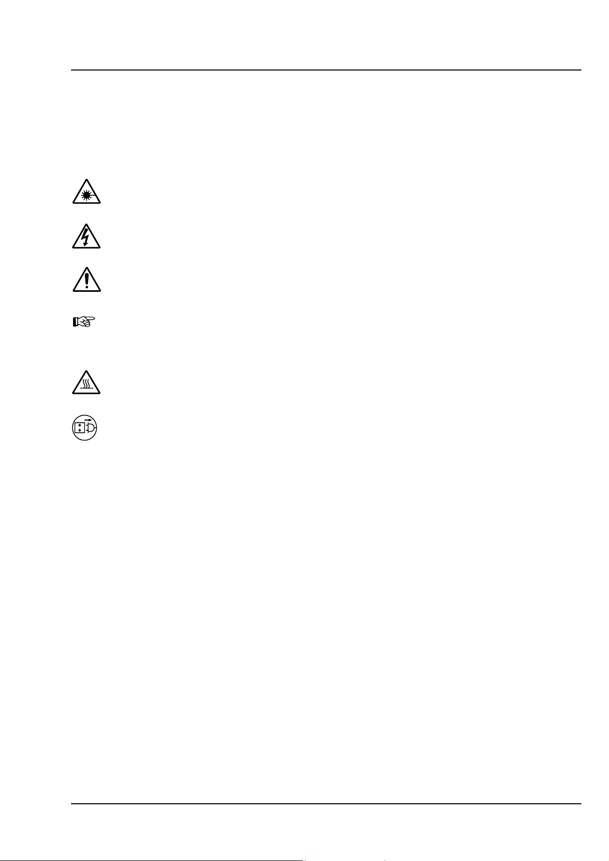
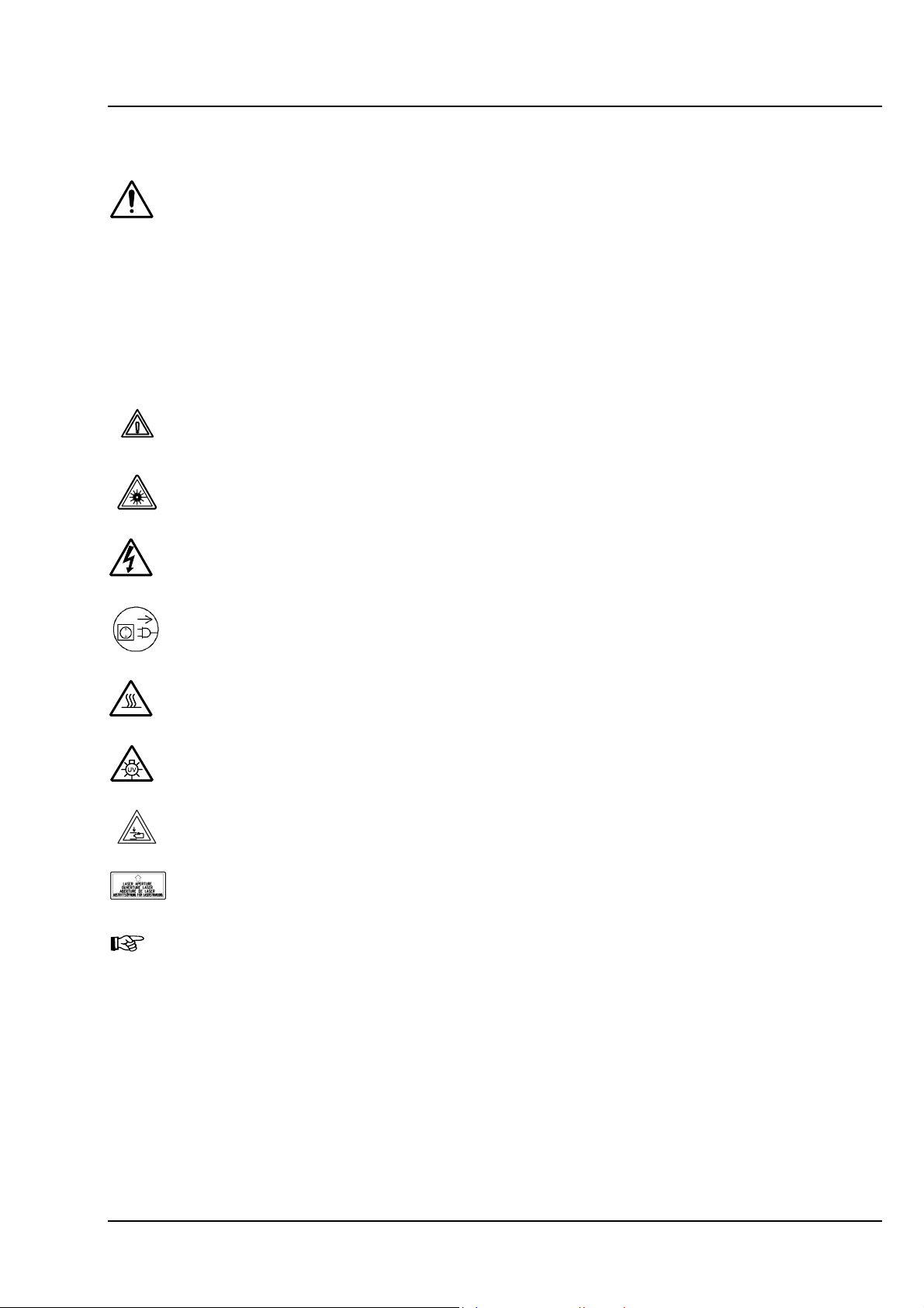
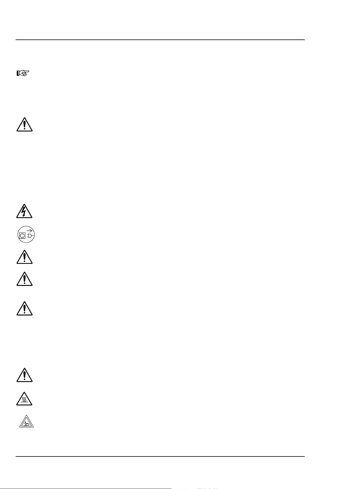
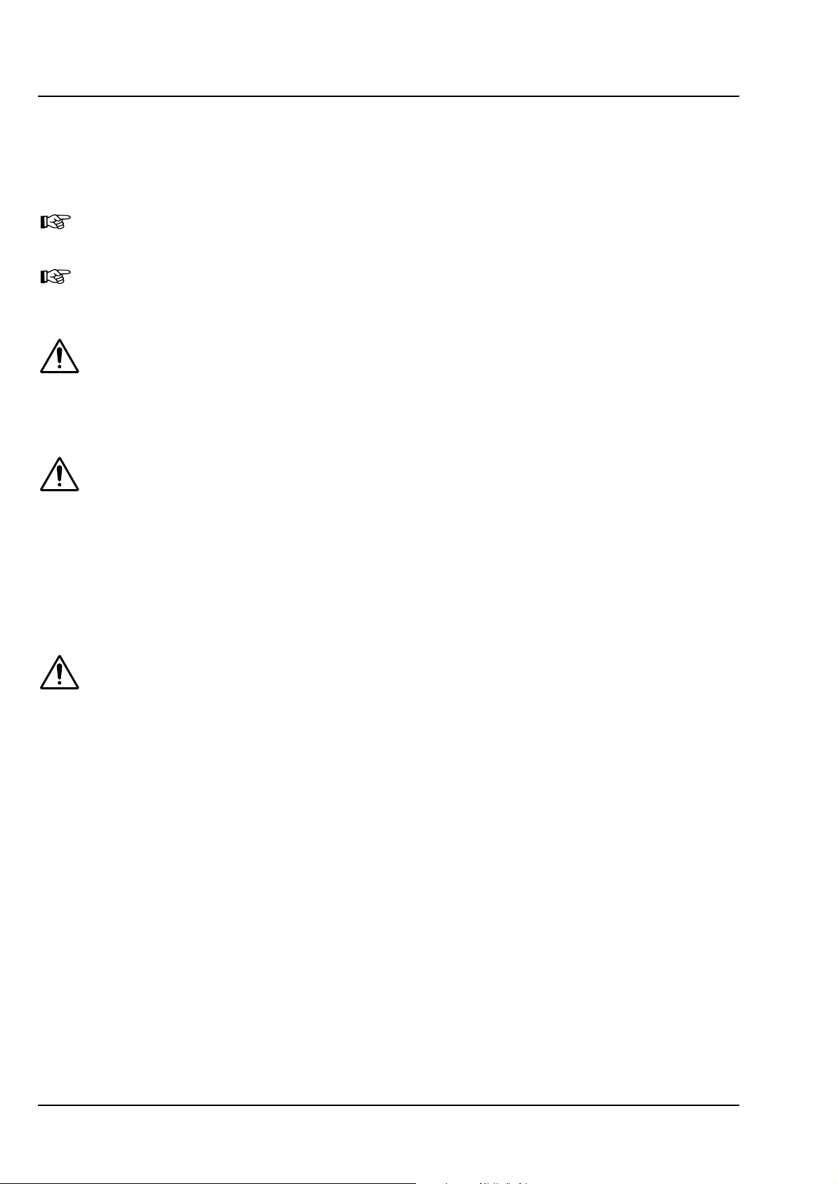
Description of labels
Caution: Faults and hazards that might arise during operation which might cause damage to
the unit or injury to the user.
Attention: Laser irradiation hazards possible when operating the system.
Attention: High voltage.
Pull the mains plug before opening the device housing.
Caution:
Hot surface.
Caution: UV radiation.
Caution: Fingers can be caught.
The arrow points to the opening where laser light comes out during operation of the system.
Other labels on the system include one of the above depicted symbols and a detailed
description of the handling instructions. See also the following drawings of the system parts.
03/06 B 45-0021 e 1-3
Page 8
NOTES ON DEVICE SAFETY LSM 510 DuoScan
Carl Zeiss Warning and Information Labels LSM 510 META DuoScan
1:1
ZERO
FOCUS
OBJECTIVE
REFLECTOR
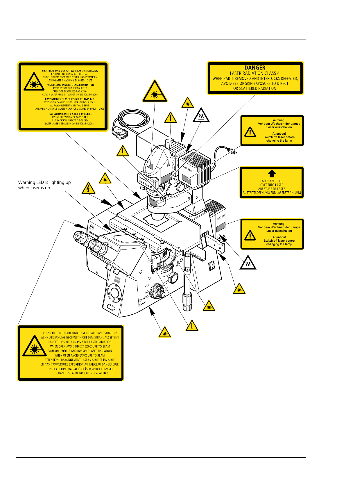
Fig. 1-1 Warning and information labels on the Axiovert 200 M microscope with the LSM 510 META
scanning module
1-4 B 45-0021 e 03/06
Page 9
LSM 510 NOTES ON DEVICE SAFETY
LSM 510 META Warning and Information Labels Carl Zeiss
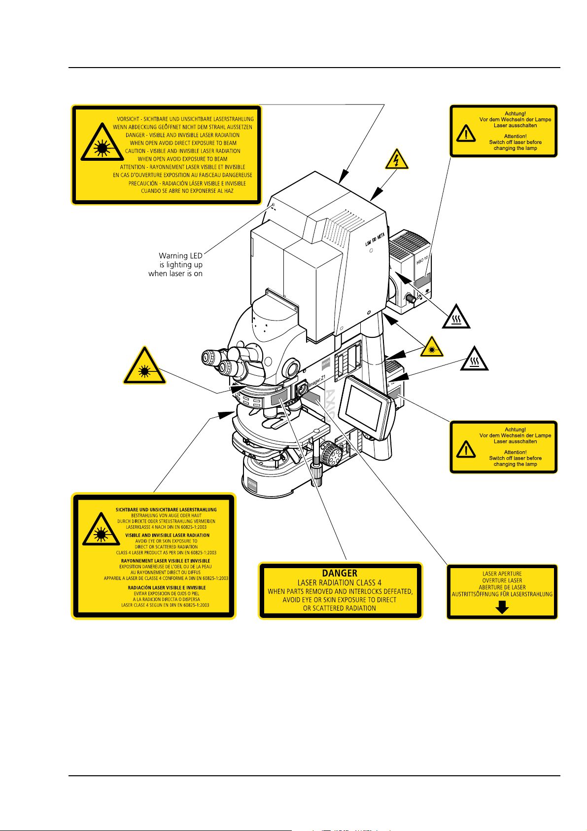
Fig. 1-2 Warning and information labels on the Axio Imager.Z1 microscope with LSM 510 META
scanning module
03/06 B 45-0021 e 1-5
Page 10

NOTES ON DEVICE SAFETY LSM 510 DuoScan
Carl Zeiss Warning and Information Labels LSM 510 META DuoScan
40
50
30
60
20
70
10
80
100
90
Fig. 1-3 Warning and information labels on the Axioskop 2 FS MOT microscope with the
LSM 510 META scanning module
1-6 B 45-0021 e 03/06
Page 11
LSM 510 NOTES ON DEVICE SAFETY
LSM 510 META Warning and Information Labels Carl Zeiss
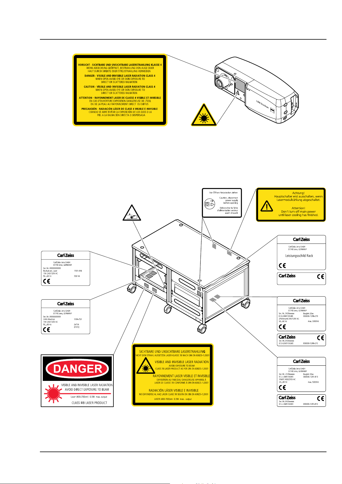
Fig. 1-4 Warning and information labels on LSM DuoScan (systems LSM 510 DuoScan or
LSM 510 META DuoScan only)
Fig. 1-5 Warning and information labels on the system electronic rack
03/06 B 45-0021 e 1-7
Page 12
NOTES ON DEVICE SAFETY LSM 510 DuoScan
Carl Zeiss Warning and Information Labels LSM 510 META DuoScan
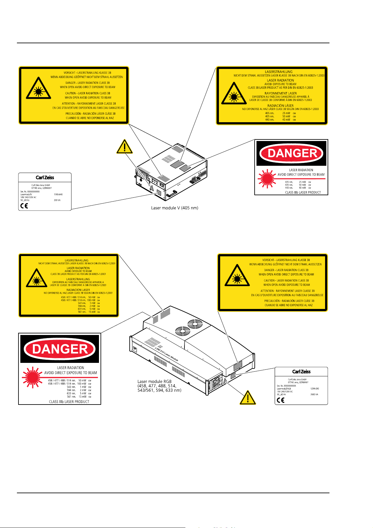
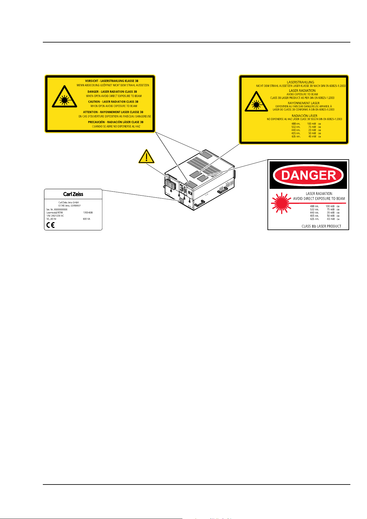
Fig. 1-6 Warning and information labels on laser components (page 1)
1-8 B 45-0021 e 03/06
Page 13
LSM 510 NOTES ON DEVICE SAFETY
LSM 510 META Warning and Information Labels Carl Zeiss
Fig. 1-7 Warning and information labels on laser module LSM 5 LIVE
03/06 B 45-0021 e 1-9
Page 14
NOTES ON DEVICE SAFETY LSM 510 DuoScan
Carl Zeiss Warning and Information Labels LSM 510 META DuoScan
COHERE
n
T
E
n
TERPRISE
PEAK
SEARCH
E
n
TERPRISE
COHERE
n
E4
J37
E5
E4
J6
T
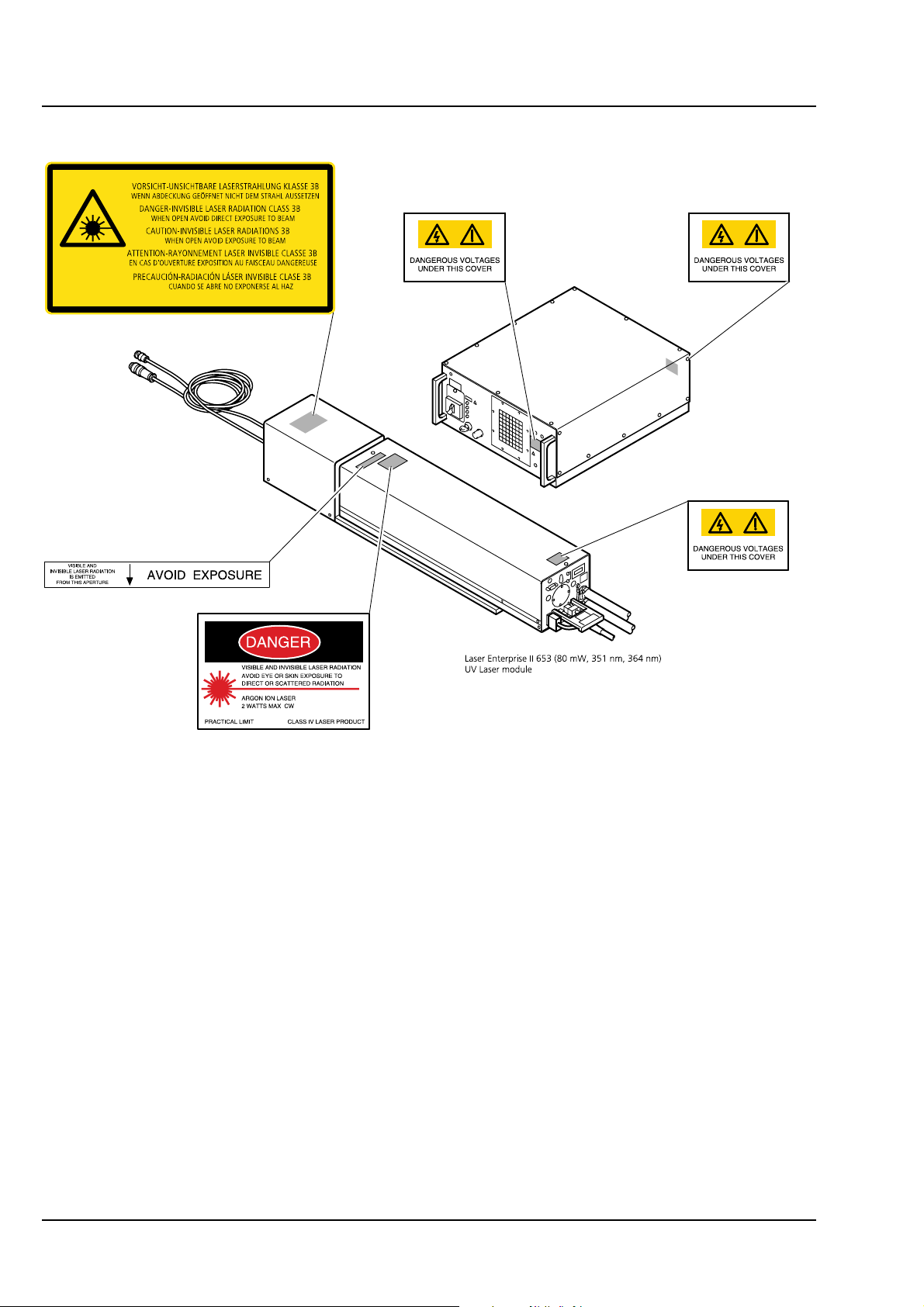
Fig. 1-8 Warning and information labels on laser components (page 2)
maximum
water
pressure
60 p.s.I.
OUT
water
1-10 B 45-0021 e 03/06
Page 15

LSM 510 NOTES ON DEVICE SAFETY LSM 510 META Regulations Carl Zeiss
1.3 Regulations
Extensive knowledge of the hardware/the system is indispensable for safe operation of the LSM 510 and
LSM 510 META.
Read these operating instructions and all device publications belonging to the system
conscientiously before operating the LSM 510 or LSM 510 META! You can obtain additional
information on the hardware configuration delivered and on optional system extensions from
the manufacturer or via the service hotline.
⇒ The LSM 510 and LSM 510 META have been designed, built and tested in conformity with the
following regulations and guidelines:
DIN EN 61010-1 (IEC 601010-1) "Safety requirements for electrical equipment for measurement,
control and laboratory use"
DIN EN 60825-1 (IEC publication 60825-1) "Safety of laser equipment", taking relevant CSA and UL
specifications into account
DIN EN 61326: “Electrical equipment for control technology and laboratory use – EMCrequirements”
Low voltage directive: 73/23/EWG
EMC directive: 89/336/EWG
⇒ The company works according to a certified Environment Management System according to
ISO 14001.
The Product was developed, tested and produced in accordance with the valid regulations and
guidelines for environmental law of the European Union.
The product and its accessories have been classified as instrument category 9 (laboratory equipment
or comparable standard). The product and its accessories agree with the EU-regulations 2002/95/EG
(RoHS) and 2002/96/EG (WEEE) , if applicable for the product.
Carl Zeiss has installed a process for taking back and recycling the instruments within the member
states of the European Union, which takes care of the appropriate utilization according to the said
EU guidelines.
For details on the disposal and recycling please refer to your relevant Carl Zeiss sales or service
organization.
The product must not be disposed in the household waste or through the municipal disposal
organizations. In case of resale the seller is obliged to inform the buyer, that the product has to be
disposed according to the said regulations.
03/06 B 45-0021 e 1-11
Page 16
NOTES ON DEVICE SAFETY LSM 510 DuoScan
Carl Zeiss Notes on Setting up the Microscope System LSM 510 META DuoScan
1.4 Notes on Setting up the Microscope System
Installation and commissioning of the LSM 510 and LSM 510 META system must be performed
by authorized Carl Zeiss service staff. The system should not be used prior to instruction by a
Carl Zeiss representative.
The LSM 510 or LSM 510 META laser scanning microscope is delivered in several crates.
The LSM 510 and LSM 510 META must be set up so as to ensure that the minimum clearance
between the wall and the rear of the system is no less than 0.5 m. This clearance is needed for
adjustment and maintenance operations.
Do not set up the unit in the proximity of heat sources such as radiators or direct sunlight. To avoid heat
build-ups, the ventilation slots on the microscope system must not be covered up.
The system must not be set up in areas with potential danger by explosives.
The unit must be connected to a properly installed socket outlet with earthing contact by means of the
mains cables supplied. Continuity of PE connection must not be affected by the use of extension leads.
The system contains components with dangerous voltage. The system must not be opened by
anybody else than authorized Carl Zeiss Service staff. Before opening the main plug has to be
disconnected.
Before connecting the mains cables, please check whether your mains voltage corresponds to
the voltage specified on the rating plate of the laser module.
For reasons of laser safety, all ports must either be equipped with the corresponding device
(scan head, camera, HBO lamp etc.) or covered with the counterpart of the laser safety kit
provided.
Maintenance, repair, modification, removal or exchange of components, or other interference
with the equipment beyond the operations described in this manual may only be carried out by
the manufacturer Carl Zeiss or by persons expressly authorized by Carl Zeiss to do so.
This applies especially to the microscope system, the laser scanning module, lasers, the PC
system, the power supply units, cable connections and other system components.
Please note that the LSM 510 and LSM 510 META are high-precision opto-electronic
instruments. Inexpert handling may easily impair their function or even damage them.
The openings for ventilation must not be covered.
There are hot surfaces on the HBO and HAL lamp.
When sliding the compact Lasermodule V in and out of the System electronic rack take care not
to catch your fingers.
1-12 B 45-0021 e 03/06
Page 17

LSM 510 NOTES ON DEVICE SAFETY
LSM 510 META Notes on Setting up the Microscope System Carl Zeiss
After installation or conversion of the LSM system, authorized specialized staff must carefully check that it
is in a proper condition and, particularly, that covers protecting against laser radiation are provided.
Tube openings or other unused mounts should always be protected against dust and moisture with the
corresponding device components or with termination covers/blind plugs.
By establishing a corresponding workplace environment, please ensure that the formation of electrostatic
charges of electronic components is avoided.
To avoid vibrations during operation, the LSM 510 and LSM 510 META should only be operated in
conjunction with the system table (vibration damping).
03/06 B 45-0021 e 1-13
Page 18

NOTES ON DEVICE SAFETY LSM 510 DuoScan Carl Zeiss Power Requirements LSM 510 META DuoScan
1.5 Power Requirements
The LSM 510 and LSM 510 META comes with a mains power supply cord and plug,
either CEE red (3/N/PE 400/230V/16A), or NEMA L 14-30P (2/N/Ground 120/240V/30A), and
with the matching mains socket outlet.
A ground wire (AWG10 green/yellow) is supplied because it is necessary to ground the system.
The connecting part on both ends of the cable is a cable eye with 8 mm inner diameter.
A suitable grounding point must be installed in the room.
For systems (220 ... 240 V AC) equipped with X-Cite 120 the mains socket outlet must be
equipped with a fuse having minimum tripping characteristic C according to IEC/EN 60898.
Line voltage 220 ... 240 V AC (±10 %) 100 ... 125 V AC (±10 %)
Line frequency 50...60 Hz 50...60 Hz
LSM incl. VIS laser
− Max. current
− Power
− Power consumption
Argon UV laser
− Line Voltage
− Max. current
− Power consumption
Class of protection I I
Type of protection IP 20 IP 20
Overvoltage category II II
3 phases at 16 A
Phase 1 = 1.9 kVA max.
Phase 2 = 1.5 kVA max.
Phase 3 = 2.6 kVA max.
5000 VA max. 5000 VA max.
208...240 V AC
(±10 %) 50 / 60 Hz
1 phase at 63 A
Note: For Line Voltage 220 V the
connector and power plug are rated
for 63 Amps, However wiring and
fuse should be rated for 32 Amps.
7000 VA max. 7000 VA max.
2 phases at 25 A
Phase 1 = 3.2 kVA max.
Phase 2 = 2.8 kVA max.
208...240 VAC
(±10 %) 50 / 60 Hz
1 phase at:
208 V: 34 Amps
230 V: 31 Amps
240 V: 29 Amps
Pollution degree 2 2
1-14 B 45-0021 e 03/06
Page 19

LSM 510 NOTES ON DEVICE SAFETY
LSM 510 META Notes on Handling the Laser Components Carl Zeiss
1.6 Notes on Handling the Laser Components
The LSM 510 and LSM 510 META are laser hazard class 3B instruments. If equipped with a Ti:Sa
Laser, the LSM 510 and LSM 510 META are devices that belong to laser hazard class 4.
This moderate and high-risk class embrace medium-power and high power lasers. You must
take care not to expose yourself to the radiation of such lasers. In particular, never look into the
laser beam! Only personnel which has been instructed on laser safety is allowed to operate the
system.
The following laser types are currently intended for use in the LSM 510 and LSM 510 META. The use of
any other lasers as the ones listed below is not authorized.
Laser Class Power
1 Ar 351/364 nm (UV) 4* 80 mW
2 Diode laser 405 nm 3B 30 mW
3 Ar/ML 458/477/488/514 nm 3B 30 mW
4 HeNe 543 nm 3B 1 mW
5 DPSS 561 nm 3B 10 mW
6 HeNe 594 nm 3B 2 mW
7 HeNe 633 nm 3B 5 mW
8 Titanium:Sapphire Laser Mai Tai (Spectra Physics)
710-990 nm (depending on the model)
9 Titanium:Sapphire Laser Chameleon (Coherent)
710-980 (depending on the model)
4 2 W
4 2 W
10 Diode laser 405 nm 3B 50 mW
11 OPSS laser 488 nm 3B 100 mW
12 DPSS laser 532 nm 3B 75 mW
* Laser type class 4, if mounted on laser module with fiber output class 3B.
Please note that for the maintenance of the UV Laser it is recommended to run the laser at
maximum power once a day if the laser is not used frequently or only at low power levels. This
enables the Autofill process which keeps up the correct tube gas pressure. This operation
prolongs the life time of the tube and prevents complete tube failure if the laser is not used
for a prolonged period of time. For details please refer to the Operator’s Manual of the UV
laser.
Please contact Carl Zeiss if you intend to use a different laser other than the ones above.
If used properly, the LSM 510 and LSM 510 META will not pose any laser radiation risks for operating
staff. Nevertheless, you should observe the following warnings:
03/06 B 45-0021 e 1-15
Page 20

NOTES ON DEVICE SAFETY LSM 510 DuoScan
Carl Zeiss Notes on Handling the Laser Components LSM 510 META DuoScan
• If necessary - insofar as specified by law - inform the laser protection officer before
commissioning the laser.
• The laser modules are equipped with a key-interlock.
• Always store keys for laser key switches and, if applicable, keys for further laser power
supply units, where they are inaccessible to persons not authorized to operate the laser.
• A red LED on the front of the scan head lights up when one or all of the lasers are switched
on.
• Do not place any reflecting objects into the beam path.
• Never open any covers or panels.
• Never look into the laser beam, not even to simply view the specimen, whether with the aid
of optical instruments or without. Otherwise you risk going blind!
• Do not leave any empty objective positions of the nosepiece uncovered.
• If a class 4 laser is attached to the system, already stray light can impose danger to the
operator.
• With class 4 lasers take special care of fire protection requirements. Do not use or store
flammable or explosive solids, fluids or gases in the vicinity of the system.
• Class 4 lasers can inflame also flammable materials like cloth or paper. Do not put such
materials into the beam path.
• Do not reach into the process beam inside the sample area whenever the Class 4 laser is
active!
Suitable protective measures must be taken if gases, dust or vapors hazardous to health,
secondary radiation or explosive objects should arise on the specimen as a result of laser
radiation.
For NLO systems equipped with a specific push and click filter for NDD imaging be aware that
the NDD reflector cube in the reflector turret leads to a strong back reflection of HBO light into
the specimen plane and the eyepiece. When observing the specimen through the ocular lens
the use of the NDD reflector cube should be avoided. The light flash is not harmful but
unpleasant. The reflex of closing the eyelid is sufficiently protective. To completely avoid this
situation an additional filter (#1261-345) can be mounted into the NDD reflector cube which
prevents the back reflection of the HBO light in the ocular plane.
1-16 B 45-0021 e 03/06
Page 21

LSM 510 NOTES ON DEVICE SAFETY LSM 510 META Physical Dimensions Carl Zeiss
1.7 Physical Dimensions
Length (cm) Width (cm) Height (cm) Weight (kg)
Large system table 150 80 78 100
Small system table 65 80 78 60
Passively damped anti-vibration table 130 100 75 137
Active anti-vibration table (NLO)
for Mai Tai Laser or Chameleon
Active anti-vibration table (NLO)
for Verdi Mira or Millenia Tsunami
Laser
Scanning Module LSM 510 25 20 25 15
Scanning Module LSM 510 META 28 27 30.5 13
Scanning Module LSM DuoScan 40 15 13 8
Microscope 50 35 50 20
Laser Module RGB 110 70 28 95
Laser Module, UV 140 20 20 60
Laser Module V (405 nm) 66 52 22 30
Plug-in unit external laser 66 52 22 9
System Electronic Rack 110 70 58 90
Power supply for Ar (UV) 50 50 30 30
Cooling unit for Ar (UV) 80 45 50 30
Laser Module LIVE 66 52 22 58
120 140 75 200
180 140 75 400
1.8 Environmental Requirements
1. Operation, specified performance T = 22 °C ± 3 °C without interruption (24 h a day
independently whether system is operated or
switched-off)
2. Operation, reduced performance T = 10 °C to 35 °C, any conditions different from 1.
and 5.
3. Storage, less than 16 h T = -40 °C to 55 °C
4. Storage, less than 6 h T = -55 °C to 70 °C
5. Temperature gradient ± 0.5 °C/h
6. Warm up time 1 h, for high-precision and/or long-term measurements ≥ 3 h
7. Relative humidity < 65 % at 30 °C
8. Operation altitude max. 2000 m
9. Loss of heat 4 kW
These requirements do not include the requirements for high precision measurements. Please
refer to the Operator’s Manual of the microscope for these requirements.
03/06 B 45-0021 e 1-17
Page 22
NOTES ON DEVICE SAFETY LSM 510 DuoScan
Carl Zeiss Notes on Handling the Computer and Data Media LSM 510 META DuoScan
1.9 Notes on Handling the Computer and Data Media
The computer used as standard in your LSM system is an IBM-compatible high-end Pentium computer
with WINDOWS XP operating system.
Do make sure, though, that you receive your LSM system with the operating system installed,
with initialization and start files set up and with the LSM program also installed.
When working with the hard disk, it is important to know that the more data it contains, the
slower its operation will become. Therefore, data that you do not need permanently should be
stored on other external devices.
When handling diskettes and USB sticks, avoid data losses by protecting them against extreme
temperatures, moisture and magnetic fields. The data on a diskette is stored in the form of
magnetic signals. To some extent, monitors, telephones or even lamps generate magnetic fields
that might destroy this data. Also, never open the metal cover on diskette cases. A diskette’s
surface can also be destroyed by touching it.
When handling CDs, CD ROMs or DVDs, do not touch the data side of the disc (the side of the
disc with no label or printing).
Do not apply paper labels or write on any part of the disc, data side or label side. If dust or
fingerprints get on the disc, wipe it with a soft cloth from the center to the edge, but do not
use benzine, paint thinner, record cleaner, or static repellent. This can damage the disc.
Do not place the disc in any place where it is exposed to direct sunlight or high temperatures.
Backup your data on a regular basis.
Do not install any other software without talking to your Carl Zeiss representative.
Never turn your computer off before you have terminated the LSM program and run down the
WINDOWS XP operating system. Otherwise, the program and/or data files may get lost.
1-18 B 45-0021 e 03/06
Page 23

LSM 510 NOTES ON DEVICE SAFETY
LSM 510 META Notes on Care, Maintenance and Service Carl Zeiss
1.10 Notes on Care, Maintenance and Service
The manufacturer of the unit cannot be held liable for damage resulting from operating errors,
negligence or unauthorized tampering with the device system, particularly as the result of removal or
replacement of parts of the unit or as the result of the use of unsuitable accessories from other
manufacturers.
Any such action will render all warranty claims null and void and also laser safety is no longer warranted.
You are well advised to arrange a service agreement with your nearest Carl Zeiss representative to
guarantee perfect functioning of the microscope system in the long term.
Modifications and conversion work on the components of the system must only be carried out by the
manufacturer, by the service agency or by persons authorized and trained for this purpose by the
manufacturer.
Damaged units or parts may only be repaired or maintained by the responsible service agency.
During maintenance or repair carried out by the service personnel the customer is requested to stand
aside and wear a pair of laser safety goggles if needed.
Before opening the housing of the halogen lamp switch off all laser units.
Care operations that may be carried out by operating staff are limited to cleaning painted and glass
surfaces.
• Before cleaning the instrument make sure the main power supply is disconnected.
• Cleaning painted surfaces
To do this, use a clean cloth that has been moistened in a mixture of water and some detergent; do
not use any solvent, however. Dry with a lint-free cloth.
• Cleaning glass surfaces
Glass surfaces that have become soiled or which are marked with fingerprints may be rubbed with a
clean optical cleaning cloth.
If soiling is persistent, dip the optical cleaning cloth into a mixture of distilled water and a small
quantity of detergent.
To complete cleaning, lightly breathe on the glass surface and rub it dry with a clean cloth. Lint or dust
is best removed with a clean brush.
• Make sure that no cleaning liquid penetrates into the system.
• Dust filters in the ventilation entries of the system electronic rack have to be replaced every 6 month.
For replacement please contact your local service representative.
03/06 B 45-0021 e 1-19
Page 24

NOTES ON DEVICE SAFETY LSM 510 DuoScan Carl Zeiss User Interface LSM 510 META DuoScan
1.11 User Interface
All user interface ports are equipped with a safety interlock system which warrants laser safety.
These interlock devices must not be manipulated. Other interfaces which are not described here
are service interfaces and are only to be operated by authorized Carl Zeiss service personnel.
The following devices can be mounted and dismounted by the user:
− Halogen and HBO lamp
− Transmission PMT
− Switching Mirror
− Scan head
1.11.1 Mounting and Dismounting Lamps, TPMT and Switching Mirror
The ports of the lamps, the switching mirror and the transmission PMT are equipped with hardware
interlock devices. At most ports (all ports of the Axioskop 2 FS
MOT and the Axio Imager.Z1 as well as the
HBO port of the Axiovert 200 M) the following interlock devices are present and have to be operated in
the following way:
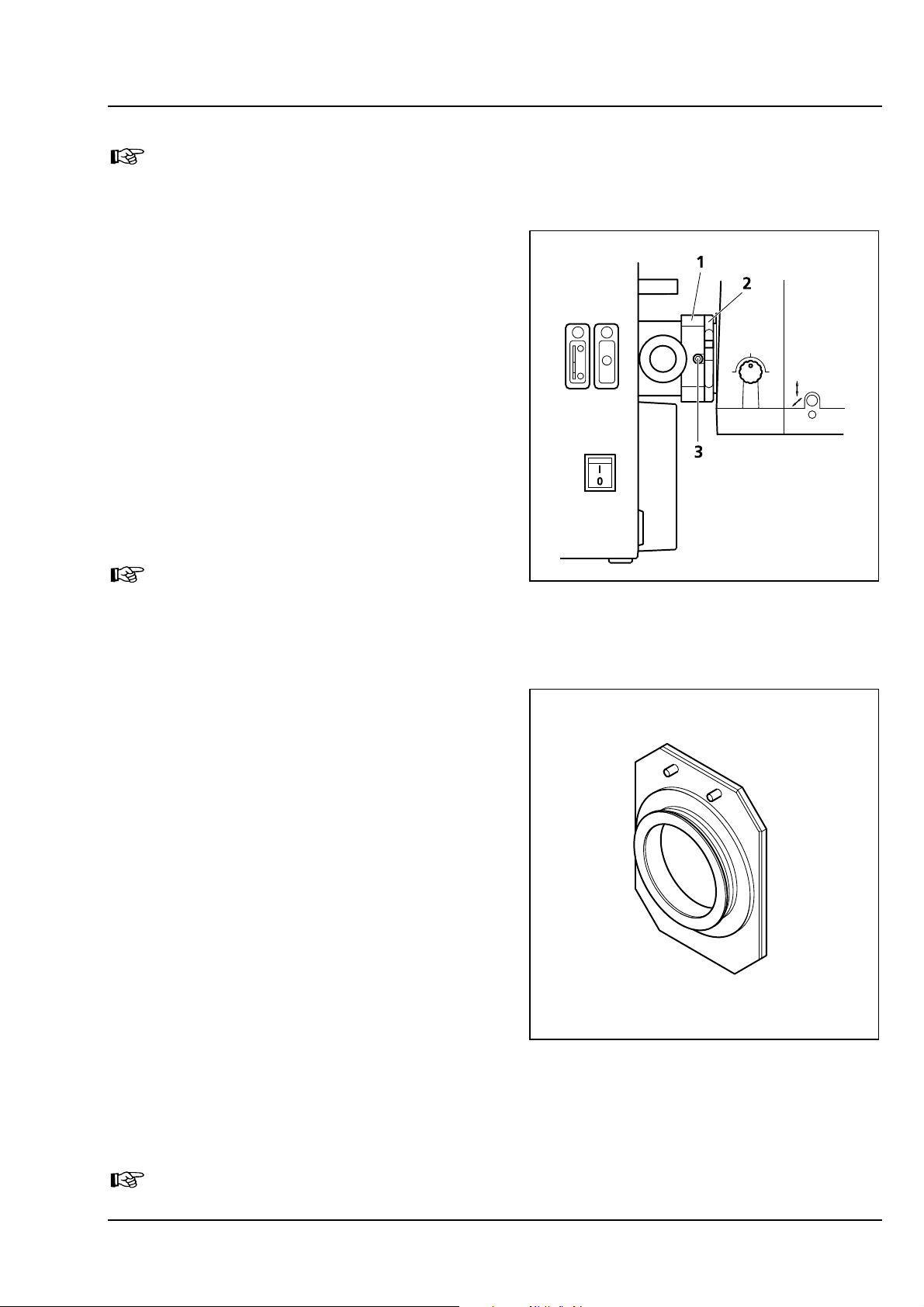
Interlock with sensor ring and contact ring:
Fig. 1-9 Sensor ring mounted to the interface
ports on the microscope side
Fig. 1-10 Contact ring mounted to the lamp,
TPMT or switching mirror
The interlock is working when the sensors of the sensor ring (
contact ring (
Fig. 1-10/1). Whenever this is not the case, for example if the distance between the two
Fig. 1-9/1) are depressed by the pins on the
devices is too large, the laser will be blocked and the system cannot be used.
1-20 B 45-0021 e 03/06
Page 25
LSM 510 NOTES ON DEVICE SAFETY
LSM 510 META User Interface Carl Zeiss
In case the system is not operating following the removal or attachment of any device on a port
with safety interlock check again the connection of the Contact ring to the Sensor ring.
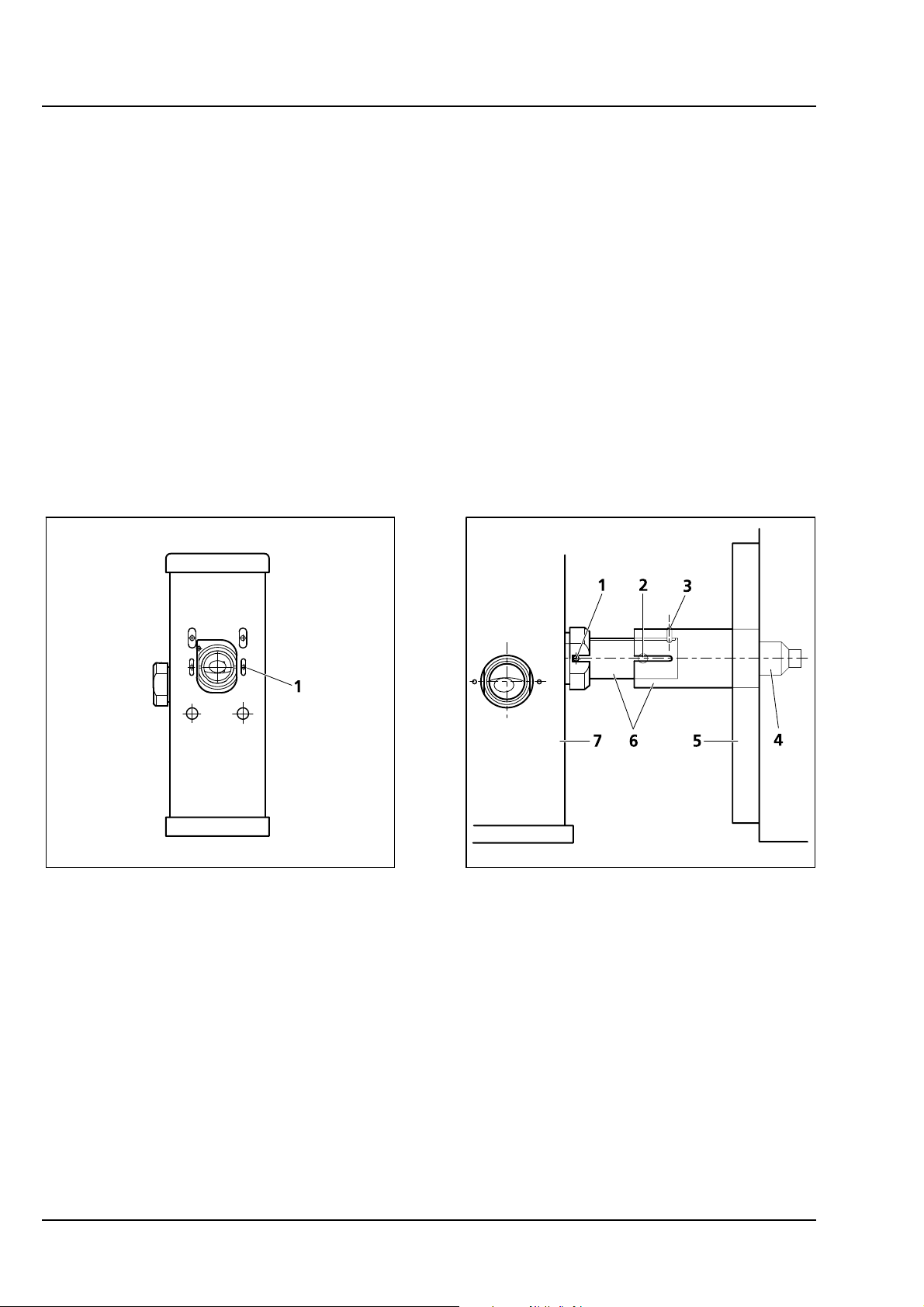
For dismounting the lamps, TPMT or switching
mirror slightly unscrew the contact ring first
(
Fig. 1-10/2 or Fig. 1-11/2) so it can be moved
away from the sensor ring (
Fig. 1-11/1). Then
unscrew the lamp, TPMT or switching mirror (main
screw
Fig. 1-11/3) which is in one of the recesses of the
sensor ring (
Fig. 1-9/2). Hold the device to be
dismounted with one hand while unscrewing to
keep it from dropping. The now empty port has to
be closed with the blind cap to restore the
functionality of the system.
Use the main screw of
the port to fix the cap. Make sure the pins of the
cap depress the sensors of the sensor ring.
Do not remove the sensor ring from
the microscope. This might result in
failure of laser safety and a non
operating system.
For mounting any lamp, TPMT or the switching
mirror back onto the microscope reverse the steps
for dismounting the device. Be careful not to bend
the pins on the contact ring when screwing the
device onto the microscope port.
For the Axiovert 200 M transmission port and the
two ports available on the motorized switching
mirror no sensor ring is present. Instead the
sensors are directly installed at the Axiovert 200 M
transmission port or the two ports of the
motorized switching mirror.
Fig. 1-11 HBO lamp mounted to
Axiovert 200 M with sensor
ring and contact ring for laser
safety
1.11.2 Mounting and Dismounting the
Scan Heads
The scan heads are connected to the microscope
via an integrated safety interlock. They can be
Fig. 1-12 Blind cap for closing any port
equipped with an interlock device
moved between two microscopes. Make sure the
system is shut off completely before starting the
following procedure:
Be aware that the scan head weights up to 15 kg.
03/06 B 45-0021 e 1-21
Page 26
NOTES ON DEVICE SAFETY LSM 510 DuoScan
Carl Zeiss User Interface LSM 510 META DuoScan
Moving the scan heads between Axiovert 200 M, Axioskop 2FS
• LSM 510 META scan head: Remove the blue cover from the back of the scan head (
Fig. 1-14).
MOT and Axio Imager.Z1:
⇒
Fig. 1-13 and
Fig. 1-13 Rear view of META scan head
• Loosen the screw on the lower end of the scan head (
Fig. 1-14 Rear view of META scan head with
blue cover removed
Fig. 1-15/1 and Fig. 1-16/1)
Fig. 1-15 Position of the screw on the
LSM 510 META scan head
1-22 B 45-0021 e 03/06
Fig. 1-16 Position of the screw on the
LSM 510 scan head
Page 27

LSM 510 NOTES ON DEVICE SAFETY
LSM 510 META User Interface Carl Zeiss
• Loosen the screws on the port to the microscope for Axiovert 200 M (
Axio Imager.Z1 and Axioskop 2 FS
MOT (Fig. 1-18/1).
Fig. 1-17 Port connection between LSM and
Axiovert 200 M
Fig. 1-18 Fastening screws of the scan
head at the front of the tube
on Axioskop 2 FS
Axio Imager.Z1
Fig. 1-17/1) or to the tube on
MOT and
• Slowly pull the scan head away from the microscope port or the tube. For mounting the scan head
onto a microscope, make sure the pins and the electronic connections of the safety interface match
closely. Fasten the screws on the front of the tube (
followed by fastening the screw on the back of the scan head (
• Use the three fastening screws (
Fig. 1-19/1) to attach or detach the LSM DuoScan to or from the
Fig. 1-18/1) or at the microscope port (Fig. 1-17/1)
Fig. 1-15/1 and Fig. 1-16/1).
microscope stand.
Fig. 1-19 Fastening screws and connections on LSM DuoScan
03/06 B 45-0021 e 1-23
Page 28
NOTES ON DEVICE SAFETY LSM 510 DuoScan
Carl Zeiss User Interface LSM 510 META DuoScan
For NLO systems being coupled to a Chameleon or Verdi Mira Laser from Coherent using the beam
housing kit designed for LSM 510, the beam tube connecting the periscope and the scan head has to be
removed before the scan head can be dismounted. Perform the following steps for the removal of the
tube:
• Unfasten the screw that clamps the outer tube to the inner tube (
• Pull out the tube from the periscope cover by sliding the inner tube into the outer tube (
• Turn the outer tube counter clockwise to unscrew the tube (
Fig. 1-21/3).
Fig. 1-21/6).
Fig. 1-21/4) from the small black tube
which is fixed to the scan head.
• Now the tube can be removed and you can proceed as described above.
• For rearranging the beam housing, first screw the tube to the scan head (
Fig. 1-21/4). It should not be
fastened completely to allow the inner tube to fit the side pin into the recess of the ring on the
periscope (
• Open the shutter in the periscope using an Allen key (
Fig. 1-21/1) and the recess of the outer tube (Fig. 1-21/2).
Fig. 1-20/1) and slide in the tube completely,
this will hold the shutter open.
Fig. 1-20 Shutter opening on the periscope.
Also applies for the large periscope
for upright microscopes.
Fig. 1-21 Tube connection from the periscope
housing (7) to the scan head (5).
Applies for upright and inverted
microscopes.
1-24 B 45-0021 e 03/06
Page 29
LSM 510 NOTES ON DEVICE SAFETY
LSM 510 META User Interface Carl Zeiss
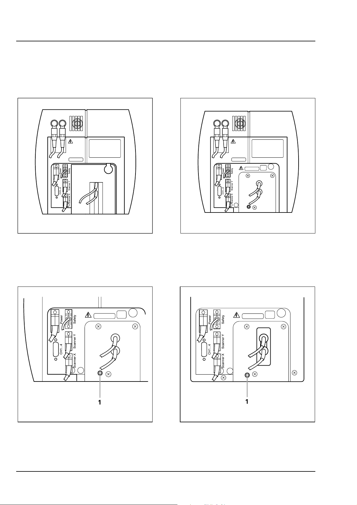
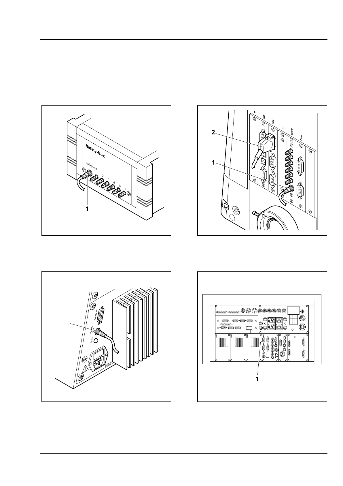
To ensure functioning of the system and laser safety the following connections have to be changed:
1. The connection of the microscope to the safety interface of the system is located either on the
additional Safety-Box (Axioskop 2 FS
200 M or Axio Imager.Z1;
Fig. 1-23/1 and Fig. 1-24/1). This connection has to be unplugged from
MOT, Fig. 1-22/1) or on the rear side of the microscope (Axiovert
the microscope which is not in use and plugged into the microscope to be used following the
exchange of the scan head.
Fig. 1-22 Safety-Box of Axioskop 2 FS MOT
with main connection to safety
interface (1)
1
Fig. 1-24 Connection of Axiovert 200 M to
safety interface (1)
Fig. 1-23 Connection of Axio Imager.Z1
to safety interface (1) and
electronics (2)
Fig. 1-25 Four CAN connections (1) are
available on the rear side of the
electronics module. The microscope
in use has to be connected to one
of them
03/06 B 45-0021 e 1-25
Page 30

NOTES ON DEVICE SAFETY LSM 510 DuoScan
Carl Zeiss User Interface LSM 510 META DuoScan
2. The plug for the main connection of the
microscope to the electronics is situated on
the rear side of the electronics rack. It is either
of the four CAN connections shown in
Fig.
1-25. Only ONE microscope can be connected
to the electronics at a time. The connection
has to be plugged in and unplugged at the
electronics rack. The corresponding
connections on the microscopes are shown in
Fig. 1-23/2,
Fig. 1-26/1 and Fig. 1-27/1. Remove the
connection of the microscope no longer in use
at the electronics rack and plug in the
connection of the microscope which should be
used instead.
Fig. 1-26 CAN connections on the
Axiovert 200 M (1). One of
the plugs is occupied with the
connection to the electronics
Fig. 1-27 The Axioskop 2 FS MOT is connected
to the electronics via the Interface
Control. The CAN connection is
fixed (1) to the control box
3. After the connections of the non used
microscope are disconnected and the ones of
the used microscope are connected, the
system can be switched on again. Before
initializing the system with the LSM Software
make sure to use the right database according
to the microscope in use. It can be chosen via
the icon Stand Select.
1-26 B 45-0021 e 03/06
Page 31

LSM 510 LSM 510 AND LSM 510 META - SETUP REQUIREMENTS
LSM 510 META Contents Carl Zeiss
CHAPTER 2 LSM 510 AND LSM 510 META -
SETUP REQUIREMENTS
CONTENTS
Page
2
LSM 510 AND LSM 510 META - SETUP REQUIREMENTS ...............................................2-2
2.1 Space Requirements...........................................................................................................2-2
2.1.1 LSM on large system table (one microscope, upright or inverted): 2 m × 3,50 m.................2-2
2.1.2 LSM on small system table (one microscope, upright or inverted): 2 m x 3,5 m...................2-3
2.1.3 LSM on passive anti vibration table (one microscope, upright or inverted): 2,2 m x 4,2 m ..2-4
2.1.4 LSM with Ar UV Laser ........................................................................................................2-5
2.1.5 LSM 510 or LSM 510 META equipped with LSM DuoScan UV ............................................2-7
2.1.6 LSM prepared for Two Photon Laser (NLO) .........................................................................2-8
2.2 Power Requirements ........................................................................................................2-10
2.3 Physical Dimensions .........................................................................................................2-14
2.4 Dimension of Shipment Crates .........................................................................................2-15
2.5 Environmental Requirements............................................................................................2-15
2.6 Vibrations ........................................................................................................................2-16
2.7 Microscopes.....................................................................................................................2-16
2.8 Scanning Module LSM 510 and LSM 510 META...............................................................2-17
2.9 Scanning Module LSM DuoScan.......................................................................................2-17
2.10 Laser Module RGB (458, 477, 488, 514, 543 or 561,594, 633 nm) ..................................2-18
2.11 Laser Module V (405 nm) .................................................................................................2-18
2.12 Laser Module UV (351, 364 nm).......................................................................................2-18
2.13 Laser Module LIVE for LSM DuoScan ................................................................................2-18
2.14 System Overview LSM 510 META .....................................................................................2-19
2.15 System Overview LSM 510 META DuoScan.......................................................................2-21
03/06 B 45-0021 e 2-1
Page 32

LSM 510 AND LSM 510 META - SETUP REQUIREMENTS LSM 510 DuoScan Carl Zeiss Space Requirements LSM 510 META DuoScan
2 LSM 510 AND LSM 510 META - SETUP REQUIREMENTS
2.1 Space Requirements
2.1.1 LSM on large system table (one microscope, upright or inverted): 2 m × 3,50 m
Fig. 2-1 Space requirements for LSM on large system table
(measurements in mm)
The System Electronic Rack contains all electronics for control of the hardware components of the
LSM system, the power supply for the microscope, the scanning unit, the Laser Module V and the
Laser Module RGB equipped with the choice of lasers. The Laser Module RGB is set on top of the System
Electronic Rack.
On this table the extension of the system with LSM DuoScan is not possible!
2-2 B 45-0021 e 03/06
Page 33

LSM 510 LSM 510 AND LSM 510 META - SETUP REQUIREMENTS
LSM 510 META Space Requirements Carl Zeiss
2.1.2 LSM on small system table (one microscope, upright or inverted): 2 m x 3,5 m
Fig. 2-2 Space requirements for LSM on small system table
(measurements in mm)
The System Electronic Rack contains all electronics for control of the hardware components of the
LSM system, the power supply for the microscope, the scanning unit, the Laser Module V and the
Laser Module RGB equipped with the choice of lasers. The Laser Module RGB is set on top of the System
Electronic Rack.
On this table the extension of the system with LSM DuoScan is not possible!
03/06 B 45-0021 e 2-3
Page 34

LSM 510 AND LSM 510 META - SETUP REQUIREMENTS LSM 510 DuoScan
Carl Zeiss Space Requirements LSM 510 META DuoScan
2.1.3 LSM on passive anti vibration table (one microscope, upright or inverted):
2,2 m x 4,2 m
Fig. 2-3 Space requirements for LSM on Passively Damped Anti Vibration Table (system
table with breadboard).
Depending on the ordered table it might be turned by 90°.
(measurements in mm)
The System Electronic Rack contains all electronics for control of the hardware components of the
LSM system, the power supply for the microscope, the scanning unit, the Laser Module V and the
Laser Module RGB equipped with the choice of lasers. The Laser Module RGB is set on top of the System
Electronic Rack. With the extension of LSM DuoScan (VIS and/or 405 nm) the Laser Module LIVE is
situated in the System Electronic Rack. It substitutes the Laser module V. With the extension of LSM
DuoScan UV the system has to be set up according to chapter
2.1.5
2-4 B 45-0021 e 03/06
Page 35

LSM 510 LSM 510 AND LSM 510 META - SETUP REQUIREMENTS
LSM 510 META Space Requirements Carl Zeiss
2.1.4 LSM with Ar UV Laser
We recommend placing the cooling unit of the Ar laser (UV) in a separate room to prevent heat
accumulation and vibration. Length of the water hose: 400 cm
One microscope: 2,5 m x 3 m
Fig. 2-4 Space requirements for LSM using one microscope
and AR UV Laser
(measurements in mm)
03/06 B 45-0021 e 2-5
Page 36

LSM 510 AND LSM 510 META - SETUP REQUIREMENTS LSM 510 DuoScan
Carl Zeiss Space Requirements LSM 510 META DuoScan
Two microscopes: 3 m x 3 m
Fig. 2-5 Space requirements for LSM with two microscopes
and AR UV Laser
(measurements in mm)
The System Electronic Rack contains all electronics for control of the hardware components of the
system, the power supply for the microscope, the scanning unit and the Laser Module RGB equipped
with the choice of lasers. The Laser Module RGB is set on top of the System Electronic Rack. The lab cart
holds the power supply for the UV laser and the UV Laser module.
On this table the extension of the system with LSM DuoScan is not possible (see chapter 2.1.5)!
2-6 B 45-0021 e 03/06
Page 37

LSM 510 LSM 510 AND LSM 510 META - SETUP REQUIREMENTS
LSM 510 META Space Requirements Carl Zeiss
2.1.5 LSM 510 or LSM 510 META equipped with LSM DuoScan UV
Fig. 2-6 Space requirements for LSM equipped with LSM DuoScan and AR UV Laser
(measurements in mm)
The System Electronic Rack contains all electronics for control of the hardware components of the
LSM system, the power supply for the microscope, the scanning unit and the Laser Module RGB
equipped with the choice of lasers. The Laser Module RGB is set on top of the System Electronic Rack.
An additional lab cart is recommended which then contains the plug in unit for the UV laser and on top
of it the UV laser itself.
03/06 B 45-0021 e 2-7
Page 38

LSM 510 AND LSM 510 META - SETUP REQUIREMENTS LSM 510 DuoScan
Carl Zeiss Space Requirements LSM 510 META DuoScan
2.1.6 LSM prepared for Two Photon Laser (NLO)
2.1.6.1 Coherent "Chameleon" or Spectra Physics “Mai Tai”. Directly-coupled to upright or
inverted Microscope: 2,5 m x 4 m
Fig. 2-7 Space requirements for Two Photon Laser and
Small NLO System Table
(measurements in mm)
The System Electronic Rack contains all electronics for control of the hardware components of the
system, the power supply for the microscope, the scanning unit and the Laser Module RGB equipped
with the choice of lasers. The Laser Module RGB is set on top of the System Electronic Rack. Power supply
and cooling unit of the NLO Laser can be stored under the system table. With the extension of LSM
DuoScan (VIS and/or 405 nm) the Laser Module LIVE is situated in the System Electronic Rack. The
electronics for the NLO laser have to be set aside the System Electronic Rack. An additional lab cart
(000000-0465-515) is recommended. With the extension of the LSM DuoScan UV only additional space is
required to set up the UV laser (see chapter
2.1.4).
2-8 B 45-0021 e 03/06
Page 39

LSM 510 LSM 510 AND LSM 510 META - SETUP REQUIREMENTS
LSM 510 META Space Requirements Carl Zeiss
2.1.6.2 Coherent "Verdi Mira" or Spectra Physics “Millenia Tsunami”. Directly-coupled with
upright or inverted Microscope: 3,5 m x 3,5 m
Fig. 2-8 Space requirements for Two Photon Laser and
Large NLO System Table. Set up of one LSM system with
two microscopes
(measurements in mm)
The System Electronic Rack contains all electronics for control of the hardware components of the
system, the power supply for the microscope, the scanning unit and the Laser Module RGB equipped
with the choice of lasers. The Laser Module RGB is set on top of the System Electronic Rack. Power supply
and cooling unit of the NLO Laser can be stored under the system table. This set up can hold two
microscopes. Coherent “Chameleon” or Spectra Physics “Mai Tai” lasers can also be used. With the
extension of LSM DuoScan (VIS and/or 405 nm) the Laser Module LIVE is situated in the System Electronic
Rack. The electronics for the NLO laser have to be set aside the System Electronic Rack. An additional lab
cart (000000-0465-515) is recommended. With the extension of the LSM DuoScan UV only additional
space is required to set up the UV laser (see chapter
2.1.4).
03/06 B 45-0021 e 2-9
Page 40

LSM 510 AND LSM 510 META - SETUP REQUIREMENTS LSM 510 DuoScan Carl Zeiss Power Requirements LSM 510 META DuoScan
2.2 Power Requirements
The LSM 510 and LSM 510 META comes with a mains power supply cord and plug,
either CEE red (3/N/PE 400/230V/16A), or NEMA L 14-30P (2/N/Ground 120/240V/30A), and
with the matching mains socket outlet.
A ground wire (AWG10 green/yellow) is supplied because it is necessary to ground the
system. The connecting part on both ends of the cable is a cable eye with 8 mm inner
diameter.
A suitable grounding point must be installed in the room. For systems (220 ... 240 V AC)
equipped with X-Cite 120 the mains socket outlet must be equipped with a fuse having
minimum tripping characteristic C according to IEC/EN 60898.
Line voltage 220 … 240 V AC (±10 %) 100 … 125 V AC (±10 %)
Line frequency 50...60 Hz 50...60 Hz
LSM incl. VIS laser
− Max. current
− Power
− Power consumption
Argon UV laser
− Line Voltage
− Max. current
− Power consumption
Class of protection I I
Type of protection IP 20 IP 20
Overvoltage category II II
3 phases at 16 A
Phase 1 = 1.9 kVA max.
Phase 2 = 1.5 kVA max.
Phase 3 = 2.6 kVA max.
5000 VA max. 5000 VA max.
208...240 V AC
(±10 %) 50 / 60 Hz
1 phase at 63 A
Note: For Line Voltage 220 V the
connector and power plug are rated
for 63 Amps, However wiring and
fuse should be rated for 32 Amps.
7000 VA max. 7000 VA max.
2 phases at 25 A
Phase 1 = 3.2 kVA max.
Phase 2 = 2.8 kVA max.
208...240 VAC
(±10 %) 50 / 60 Hz
1 phase at:
208 V: 34 Amps
230 V: 31 Amps
240 V: 29 Amps
Pollution degree 2 2
2-10 B 45-0021 e 03/06
Page 41

LSM 510 LSM 510 AND LSM 510 META - SETUP REQUIREMENTS
LSM 510 META Power Requirements Carl Zeiss
Fig. 2-9 Power connector for LSM 510 / LSM 510 META and Laser Module V. Free/reserve outlets may
be used to supply power to additional equipment. No more than 1 A can be provided by
each outlet. (Scheme is turned 90° to real system.)
03/06 B 45-0021 e 2-11
Page 42

LSM 510 AND LSM 510 META - SETUP REQUIREMENTS LSM 510 DuoScan
Carl Zeiss Power Requirements LSM 510 META DuoScan
Fig. 2-10 Power connector for Laser Module RGB
(Scheme is turned 90° to real system.)
2-12 B 45-0021 e 03/06
Page 43

LSM 510 LSM 510 AND LSM 510 META - SETUP REQUIREMENTS
LSM 510 META Power Requirements Carl Zeiss
1 Key-interlock Laser ON/OFF
2 Door interlock interface
Fig. 2-11 Key-interlock Laser ON/OFF and interface for connection of door interlock
The door interlock interface is covered with a green plug to bypass a door interlock.
• To use the interface remove the top of the green plug and the bypass wire.
• Then connect the wires of the door interlock at the same position.
Two door interlocks can be connected.
03/06 B 45-0021 e 2-13
Page 44

LSM 510 AND LSM 510 META - SETUP REQUIREMENTS LSM 510 DuoScan Carl Zeiss Physical Dimensions LSM 510 META DuoScan
2.3 Physical Dimensions
Length (cm) Width (cm) Height (cm) Weight (kg)
Large system table 150 80 78 100
Small system table 65 80 78 60
Passively damped anti-vibration table 130 100 75 137
Active anti-vibration table (NLO)
for Mai Tai Laser or Chameleon
Active anti-vibration table (NLO)
for Verdi Mira or Millenia Tsunami
Laser
Scanning Module LSM 510 25 20 25 15
Scanning Module LSM 510 META 28 27 30.5 13
Scanning Module LSM DuoScan 40 15 13 8
Microscope 50 35 50 20
Laser Module RGB 110 70 28 95
Laser Module, UV 140 20 20 60
Laser Module V (405 nm) 66 52 22 30
Laser Module LIVE 66 52 22 58
Plug-in unit external laser 66 52 22 9
System Electronic Rack 110 70 58 90
Power supply for Ar (UV) 50 50 30 30
Cooling unit for Ar (UV) 80 45 50 30
120 140 75 200
180 140 75 400
Water hose for Ar (UV) 700
Fiber optic cable, VIS(ible) 300
Fiber optic cable, UV 300
Fiber optic cables at NLO systems 400
Cables 350
SCSI cable 350
2-14 B 45-0021 e 03/06
Page 45

LSM 510 LSM 510 AND LSM 510 META - SETUP REQUIREMENTS
LSM 510 META Dimensions ... / Environmental Requirements Carl Zeiss
2.4 Dimension of Shipment Crates
Crate containing Length (cm) Width (cm) Height (cm) Weight (kg)
Large system table 160 85 95 120
Small system table 90 75 80 80
Passively damped antivibration table
Active anti-vibration table
(NLO) for Mai Tai Laser or
Chameleon
Active anti-vibration table
(NLO) for Mira or Tsunami
Laser
System Electronic Rack and
Laser module
LSM, Microscope, Computer 135 90 100 150
Additional Hardware
Components
UV laser unit 125 55 50 100
UV cooling unit 120 60 90 50
145 115 115 150
145 160 110 330
200 160 110 460
135 90 100 300
135 90 61 100
2.5 Environmental Requirements
1. Operation, specified performance T = 22 °C ± 3 °C without interruption (24 h a day
independently whether system is operated or
switched-off)
2. Operation, reduced performance T = 10 °C to 35 °C, any conditions different from
1. and 5.
3. Storage, less than 16 h T = -40 °C to 55 °C
4. Storage, less than 6 h T = -55 °C to 70 °C
5. Temperature gradient ± 0.5 °C/h
6. Warm up time 1 h, for high-precision and/or long-term measure-
ments ≥ 2 h
7. Relative humidity < 65 % at 30 °C
8. Operation altitude max. 2000 m
9. Loss of heat 4 kW
03/06 B 45-0021 e 2-15
Page 46

LSM 510 AND LSM 510 META - SETUP REQUIREMENTS LSM 510 DuoScan
Carl Zeiss Vibrations / Microscopes LSM 510 META DuoScan
2.6 Vibrations
Vibrations under operation conditions
Shipping shock (LSM 510 box)
(with system table)
5 µm pp at 5 Hz 3 g
10 µm pp at 10 Hz
10 µm pp at 20 Hz
2.7 Microscopes
Inverted Axiovert 200 M BP or SP
Upright Axioskop 2 FS
MOT
Upright Axio Imager.Z1
Upright Axio Imager.M1
All ICS objectives from Carl Zeiss and their accessories can be
accommodated.
Z motor DC servomotor, opto-electronically coded
Least Z interval: 50 nm (Axiovert 200 M BP or SP)
100 nm (Axioskop 2 FS
MOT)
10 nm (Axio Imager.Z1)
25 nm (Axio Imager.M1)
Piezo Objective focus Piezo-driven single objective drive
Max. travel 250 µm; resolution 10 nm
In the unlikely case of extreme fluctuations of the external power net or
electromagnetic radiation, the piezo crystal will vary and disturbance in
the image is visible. Note that this is not a defect and the piezo drive will
not be damaged.
2-16 B 45-0021 e 03/06
Page 47

LSM 510 LSM 510 AND LSM 510 META - SETUP REQUIREMENTS
LSM 510 META Scanning Module Carl Zeiss
2.8 Scanning Module LSM 510 and LSM 510 META
Scanners 2 individually driven galvanometric scanners
Scanning speed
Field resolution
Field of view
Zoom
Channels a) Up to 4 confocal reflection/fluorescence channels (PMT) simultaneously
1 transmitted light channel (PMT) and 2 NDD
1 reference monitor diode
Fiber-optic adaptation of external detectors
Dynamic range 12-bit DAC for each detection channel
Pinholes 4 individual variable pinholes (one per confocal channel or META detector)
Computer controlled automatic alignment
Up to ~5 frames/sec (512 × 512 pixels)
Max. 2048 × 2048 pixels (individually adjustable for each axis)
10 × 10 mm² with a 1.25× objective
1× ... 40×, continuous control
or
b) 2 confocal reflection/fluorescence channels (PMT) and 1 META detector
or
3 - 4 NDD (Non descanned detectors, PMT)
2.9 Scanning Module LSM DuoScan
Scanners 2 individually driven galvanometric scanners
Scanning speed
Field of view
Up to ~5 frames/sec (512 × 512 pixels)
10 × 10 mm² with a 1.25× objective
03/06 B 45-0021 e 2-17
Page 48

LSM 510 AND LSM 510 META - SETUP REQUIREMENTS LSM 510 DuoScan
Carl Zeiss Laser Modules LSM 510 META DuoScan
2.10 Laser Module RGB (458, 477, 488, 514, 543 or 561,594, 633 nm)
Single-mode polarization preserving fiber
Laser beam attenuation for all lasers by VIS-AOTF
HeNe laser (543 nm, 1 mW)
HeNe laser (594 nm, 2 mW)
HeNe laser (633 nm, 5 mW)
DPSS laser (561 nm, 10 mW)
Ar laser (458, 477, 488, 514 nm, 30 mW)
2.11 Laser Module V (405 nm)
Single-mode polarization preserving fiber
Laser beam attenuation by UV-AOTF
Diode laser (405 nm, 30 mW)
2.12 Laser Module UV (351, 364 nm)
Single-mode polarization preserving fiber
Laser beam attenuation for all lasers by UV-AOTF
Ar laser (351, 364 nm, 80 mW)
2.13 Laser Module LIVE for LSM DuoScan
Single-mode polarization preserving fiber
Laser beam attenuation (AOTF) for all lasers
Diode laser (405 nm, 50 mW)
OPSS laser (488, 100 mW)
DPSS laser (532 nm, 75 mW)
2-18 B 45-0021 e 03/06
Page 49

LSM 510 LSM 510 AND LSM 510 META - SETUP REQUIREMENTS
LSM 510 META System Overview LSM 510 META Carl Zeiss
2.14 System Overview LSM 510 META
03/06 B 45-0021 e 2-19
Page 50

LSM 510 AND LSM 510 META - SETUP REQUIREMENTS LSM 510 DuoScan
Carl Zeiss System Overview LSM 510 META LSM 510 META DuoScan
40
50
0
3
6
0
20
70
10
8
0
100
90
2-20 B 45-0021 e 03/06
Page 51

LSM 510 LSM 510 AND LSM 510 META - SETUP REQUIREMENTS
LSM 510 META System Overview LSM 510 META DuoScan Carl Zeiss
2.15 System Overview LSM 510 META DuoScan
03/06 B 45-0021 e 2-21
Page 52

LSM 510 AND LSM 510 META - SETUP REQUIREMENTS LSM 510 DuoScan
Carl Zeiss System Overview LSM 510 META DuoScan LSM 510 META DuoScan
40
50
0
3
6
0
0
2
70
10
8
0
100
90
2-22 B 45-0021 e 03/06
Page 53

LSM 510 INTRODUCTION TO LASER SCANNING MICROSCOPY
LSM 510 META Contents Carl Zeiss
CHAPTER 3 INTRODUCTION TO LASER SCANNING MICROSCOPY
CONTENTS
Page
3
INTRODUCTION TO LASER SCANNING MICROSCOPY ...................................................3-2
3.1 Principle of Laser Scanning Microscopy...............................................................................3-2
3.2 Three-Dimensional Presentations of LSM Image Stacks .......................................................3-3
3.3 Optical Diagram of the LSM 510 and LSM 510 META (Schematic) ......................................3-4
3.4 Performance Features of the LSM 510 and LSM 510 META ................................................3-5
3.4.1 Optical and Mechanical Aspects .........................................................................................3-5
3.4.2 Microscope Equipment of the LSM 510 and LSM 510 META System...................................3-6
3.4.3 Computer Hardware and Software.....................................................................................3-8
03/06 B 45-0021 e 3-1
Page 54

INTRODUCTION TO LASER SCANNING MICROSCOPY LSM 510 DuoScan
Carl Zeiss Principle of Laser Scanning Microscopy LSM 510 META DuoScan
3 INTRODUCTION TO LASER SCANNING MICROSCOPY
3.1 Principle of Laser Scanning Microscopy
To yield information on their inner structure by conventional transmitted-light microscopy, specimens
have to be very thin and translucent; otherwise image definition will be poor. In many cases it is a
problem to satisfy these requirements.
The essential considerations have led to trailblazing changes in conventional microscopy and supplied a
successful solution to the above problem.
• Unlike the practice of even illumination in conventional microscopy, the LSM technique projects the
light of a point light source (a laser) through a high-NA objective onto a certain object plane of
interest as a nearly diffraction-limited focus. However, if not for another "trick", the stray light
produced outside the object plane, or the fluorescence of fluorescent specimens, would disturb the infocus image of object point of interest, resulting in a blurred image of poor contrast. The problem
therefore is how to capture only the light coming immediately from the object point in focus, while
obstructing the light coming from out-of-focus areas of the specimen.
• The light reflected, or the fluorescence light
produced, at the focus of the high-NA objective
is projected onto a variable pinhole diaphragm
by the same objective and a tube lens. The
focus inside the specimen and the pinhole are
situated at optically conjugate points (confocal
imaging). The decisive advantage of this
arrangement is the fact that essentially no other
light than that coming from the object plane of
interest can pass the narrow pinhole and be
registered by a detector. Unwanted light
coming from other specimen areas is focused
outside the pinhole, which passes only a small
fraction of it. The smaller the pinhole, the less
stray light or fluorescence from out-of-focus
areas will get on the detector. The image point
thus generated is largely free from blur caused
by unwanted light.
• In order to obtain an image of the selected
Fig 3-1 Principle of confocal imaging
object plane as a whole, it is necessary to scan
the object plane in a point-by-point, line-by-line
raster by means of an XY light deflection
system. The detectors - as a rule,
photomultipliers - convert the optical information into electric signals. This allows the image of any
object plane to be generated and stored within less than a second. By a defined focusing (Z axis)
movement it is possible to look at any object plane of interest. By scanning a succession of object
planes in a specimen, a stack of slice images can be produced.
This way, the LSM technique in conjunction with ICS optics (Infinity Color-Corrected System) has brought
decisive improvements over conventional microscopy in terms of resolving power and confocal depth
contrast:
Object features in the order of 0.2 μm can be resolved, and height differences of less than
0.1 μm made visible, without the use of interference methods.
3-2 B 45-0021 e 03/06
Page 55

LSM 510 INTRODUCTION TO LASER SCANNING MICROSCOPY
LSM 510 META Three-Dimensional Presentation of LSM Image Stacks Carl Zeiss
3.2 Three-Dimensional Presentations of LSM Image Stacks
One of the advantages of the LSM technique is that it can present structures in three dimensions. This
opens up many ways to process images. Outlined below are some of the possible methods to extract
spatial information from stacks of slice images.
• Gallery
The simplest presentation of 3D information is a gallery showing the individual slice images (sections)
of a stack arranged side by side, with each slice apart from the next by a defined, selectable interval
on the Z axis.
• Virtually infinite depth of focus
The entire set of data can be imaged as a single projection. The computer establishes an image
composed of all in-focus optical sections. The image produced by this so-called composite method has
a virtually infinite depth of focus, since the result is made up of information from in-focus planes only.
• Rotary animation
A sequence of projections is computed, with the specimen being apparently rotated by a certain angle
from image to image, for example by a full turn about an axis. If such a sequence is displayed on the
monitor screen in rapid succession, the visual effect is that of a rotating three-dimensional object.
• Stereo image pairs
The computer establishes a pair of images corresponding to those we see with the right and the left
eye, respectively. The two images forming the stereo pair can be shown on the monitor side by side.
They can be seen as a 3D image with suitable optical aids. Another possibility is to present both
images in registration, with one image in the red channel and the other in the green one (anaglyph).
Viewed through red and green color filters in a spectacle frame, which only pass the image intended
for the respective eye, the two images form a 3D image in the brain
• Color-coded height slices
Each level, i.e. each slice is assigned a different color. For direct evaluation, a color scale is shown,
indicating the actual height above the bottom slice.
• Orthogonal sections
This computation produces a triplet of mutually perpendicular sectional images.
• Oblique sections
A section through the stack is made along an oblique plane defined by the selection of five
coordinates, i.e. X, Y, Z, angle of rotation, and angle of tilt.
• Topography (option)
A computing program for surface topography presentations (as required in materials research) is
available.
• Physiology (option)
With a special software, kinetic processes can be tracked, which is especially of interest to physiology.
• Image VisArt (option)
Three-dimensional display of floating transparent structures (cells) or opaque structures (material
• 3D Deconvolution (option)
03/06 B 45-0021 e 3-3
)
Page 56

INTRODUCTION TO LASER SCANNING MICROSCOPY LSM 510 DuoScan
Carl Zeiss Optical Diagram of the LSM 510 LSM 510 META DuoScan
3.3 Optical Diagram of the LSM 510 and LSM 510 META (Schematic)
Fig. 3-2 Optical path, schematic (4-channel configuration)
AOTF Acousto Optical Tunable Filter
DBC Dichroic Beam Combiner
DBS Dichroic Beam Splitter
EF Emission Filter
HAL Halogen Lamp
HBO Mercury Vapor Short-Arc Lamp
LSF Line Selection Filter
MDBS Main Dichroic Beam Splitter
NDF Neutral Density Filter
VP Variable Pinhole
PMT Photomultiplier
T-PMT Transmission-Photomultiplier
The diagram above is a schematic representation of the LSM system.
Laser light is focused onto the specimen through an objective in a diffraction-limited mode. Light emitted
at the focal plane and at planes below and above it is directed via an XY scanner onto a main dichroic
beam splitter (MDBS), which separates the emissions from the excitation light. The fluorescences are
separated from each other by a series of dichroic beam splitters (DBS1 ... maximally DBS4) and directed to
individual photomultipliers (PMT1 ... maximally PMT4).
3-4 B 45-0021 e 03/06
Page 57

LSM 510 INTRODUCTION TO LASER SCANNING MICROSCOPY
LSM 510 META Performance Features of the LSM 510 … Carl Zeiss
3.4 Performance Features of the LSM 510 and LSM 510 META
3.4.1 Optical and Mechanical Aspects
The highly integrated system design makes for the shortest possible optical paths, top-grade optical
precision and high stability. The compact scanning module can be fitted to an inverted (Axiovert 200 M
BP or SP) or upright (Axio Imager.Z1, Axio Imager.M1 or Axioskop 2 FS
MOT) microscope in less than three
minutes. On the Axiovert 200 M, the scanning module may be mounted either to the base port directly
below the microscope or to the side port.
The spectral range available extends from the UV to the IR region.
For the VIS (visible-light) Laser Module, the user can select from up to six lasers with wavelengths of 633,
594, 561, 543, 514, 488, 477, 458 and 405 nm. The UV Laser Module provides wavelengths of 351 and
364 nm. A Ti:Sa Laser provides pulsed laser light from 690 to 1040 nm for Multiphoton imaging (NLO).
Coupling of the laser light is through polarization-preserving single-mode optical fibers. One variable
beam collimator each for the UV or NLO and visible ranges provides optimum adaptation of the
respective laser wavelength to the objective used and, thus, optimum correction for Z aberrations.
Acousto-optical tunable filters (AOTF) adjust the necessary brightness for up to 8 laser lines within
microseconds.
A monitor diode permanently registers the laser output; it can be used for the on-line checking of the
intensity of the exciting light. This check is also possible selectively for the different wavelengths if a line
selection filter is inserted.
The four internal image acquisition channels, usable for reflection or fluorescence, and an additional
transmitted-light channel are ideal for the investigation of multiple fluorescence specimens. Separately in
each of the four channels, the diameters of the pinholes and their XY positions can be optimized, and the
desired emission filter placed into the beam path, by servo-motor control. In the case of pinhole VP1, this
adjustment also includes positioning along Z. In the simultaneous registration of multiple fluorescence,
identical optical sections can be obtained in each confocal channel. This is of importance, e.g., with the
FISH method (fluorescence in-situ hybridization) used for genome analysis in cytogenetic studies.
The microscope's transmitted-light channel is equipped with a photomultiplier, too. It is therefore
possible to superimpose a multiple fluorescence image on a brightfield, differential interference or phase
image.
A fiber-optic cable connection to external special detectors, such as cooled PMTs or spectrometers, is also
available. It substitutes one internal detection channel.
In addition to the emission filters for all standard and special applications, available in motor-controlled
filter wheels, the user can easily install his own emission filters in two of the channels.
The high-NA C-APOCHROMAT objectives specially developed for the LSM technique reach the physical
limit in resolving power, and can be used throughout the 350...800 nm spectral range with the same
high quality, producing brilliant images.
A two-mirror scanner system, controlled by a real time electronics, offers several advantages. The large
deflection angle of the scanning mirrors allows a wide area to be scanned. With a 1.25× objective, the
object area scanned is 10 × 10 mm².
The scanning field size can be freely selected between 4 × 1 and 2048 × 2048 pixels.
It is possible to rotate the XY scanning field through 360° and carry out XY scans without having to
rotate the specimen itself under laser radiation load.
03/06 B 45-0021 e 3-5
Page 58

INTRODUCTION TO LASER SCANNING MICROSCOPY LSM 510 DuoScan
Carl Zeiss Performance Features of the LSM 510 … LSM 510 META DuoScan
Selection of the specimen detail of interest for zooming is fast and convenient, and the zoomed image is
automatically centered. This saves the job of specimen centration with the microscope stage.
Using a bi-directional scanning facility will double the scanning rate to approx. 5 frames/sec (at 512 × 512
pixels); if two different laser wavelengths are used for the two scanning directions (wavelength 1 for leftto-right, and wavelength 2 for right-to-left scanning), two fluorochrome dyes can be viewed and
documented in a quasi-simultaneous mode. This will prevent cross talk between detection channels.
The LSM 510 and LSM 510 META can be combined with a second scanner, the LSM DuoScan. Any of the
above mentioned microscopes can be used. The LSM DuoScan can be equipped either with a UV Laser or
a 405 nm laser both also together with a 488 and/or 532 nm laser. The software allows to simultaneously
image and bleach/manipulate a sample. The usefulness of this option is dependent on the sample.
3.4.2 Microscope Equipment of the LSM 510 and LSM 510 META System
The LSM 510 or LSM 510 META system is equipped either with the inverted Axiovert 200 M BP or SP
microscope or with the upright Axio Imager.Z1, Axio Imager.M1 or Axioskop 2 FS
MOT microscopes.
Only the differences from the delivered operating manual "Axiovert 200 M" will be explained here.
(1) Stand
a) The motorized objective nosepiece 5× H DIC is firmly fixed to the stand, where no operating elements
can be found for the nosepiece. Operation will be performed via LSM 5 software control. The "Restriction
of the nosepiece height to protect the objectives during motorized objective change" is inactivated. The
nosepiece will be moved down automatically before each motorized objective change.
b) The reflector mount is motorized and provided with the Axiovert 200 M reflector turret. The reflector
turret has 5 positions: One transmitting light position, which is identical to the LSM position, and four
further positions for fluorescence filter sets (reflector modules). If you want to use more than five
conventional fluorescence filter sets, it is advisable to use a further reflector turret. When changing the
reflector turret position you must make sure that the turret will click into position, since otherwise the
image area will be cut. If the system is equipped with the LSM DuoScan up to three positions (depending
on the laser equipment of the LSM DuoScan) are equipped with fixed beam combiners. Two positions of
the reflector turrent can be equipped with conventional fluorescence filter sets.
c) The stand has a motorized focusing drive (fine coarse). Sensitivity of the focusing drive is adjusted to
the delivered objectives by the manufacturer. If you want to use other objectives, sensitivity and
parfocality can be adjusted via the Axioset program.
d) The stand features an integrated power supply for the internal motors and stand electronics. The
power supply can be switched on at the right side of the stand. External power supply units will be used
for the mercury vapor short arc lamp.
e) The analyzer slider for conventional DIC methods will be operated from the right side and is located
just below the nosepiece.
When the rod is pushed in, the analyzer is located in the beam path. In the LSM-mode, the analyzer must
not be located in the beam path, and the analyzer rod must be pulled out.
(2) Specimen stages and fine focus drives
a) Mechanical stage
The stage with coaxial drive must be mounted on the right side of the stand.
b) Scanning stage
c) Piezo objective focus drive
3-6 B 45-0021 e 03/06
Page 59

LSM 510 INTRODUCTION TO LASER SCANNING MICROSCOPY
LSM 510 META Performance Features of the LSM 510 … Carl Zeiss
(3) Transmitted-light illumination
a) The illuminator support contains a security circuit which activates a shutter preventing laser light from
reaching the stand when the support is moved to the back. A complementary shutter built in the stand
prevents laser light from reaching the eyepieces during the scanning mode.
b) The illuminator support is equipped with a rotary polarizer. The Axiovert 200 M description contains
the adjustment for the DIC mode during conventional observation.
For scanning in the transmitted-light DIC mode, the polarizer in the transmitted light support works like
an analyzer and must be adjusted in such a manner that direct laser light will be blocked.
The conventional analyzer slider in the stand must not be located in the beam path because the laser
light is already polarized.
c) A fully motorized, LSM 5 software-controlled switching mirror is mounted on the illuminator support.
Alternatively, the light is directed to the LSM 5 transmitted-light detector or enables conventional
transmitted-light observation.
d) The focusing screen for conventional transmitted-light is located in a support in front of the halogen
lamp housing.
e) Further information on the halogen lamp and the condensers is provided in the Axiovert 200 M
operating manual.
(4) Reflected light fluorescence
With the exception of the reflector slider, all the Axiovert 200 M fluorescence accessories can be used.
Further information is provided in the Axiovert 200 M operation manual.
(5) Imaging optics
Optovar sliders cannot be used.
The analyzer for the conventional DIC mode will be operated from the right side and is located just below
the nosepiece.
Use of sliders with auxiliary objects (473704/14-0000-000) is not possible.
(6) Photo equipment
The stand does not feature an integrated SLR-port, but microscope cameras as described in the
Axiovert 200 M and LSM 510 / LSM 510 META operation manual can be used.
(7) TV adaptation
The TV port at the side and the tubes can be used as described in the Axiovert 200 M operation manual.
The TV interface side port can be used with TV adapters 60 N or LSM adapters.
03/06 B 45-0021 e 3-7
Page 60

INTRODUCTION TO LASER SCANNING MICROSCOPY LSM 510 DuoScan
Carl Zeiss Performance Features of the LSM 510 … LSM 510 META DuoScan
3.4.3 Computer Hardware and Software
The LSM 510 and LSM 510 META is controlled via a standard high-end Pentium PC. Linking to the
electronic control system is made via Gigabit Ethernet interface. The PC comes with the WINDOWS XP
operating system.
The instrument is fully motorized, permitting fast change-over between methods as well as automatic
operation. Parameters once set or complex examination sequences once established can be saved and
reproduced; therefore, complete application programs can be loaded and performed by pushbutton
control.
The software of the LSM 510 and LSM 510 META have two levels. On the simple operator interface level,
a result will be achieved after a few prompts; graphical prompting of the user in conjunction with
automatic setting of many parameters is an ideal tool for daily routine jobs. The expert level offers perfect
facilities for individual settings of functions and parameters.
Conversion of the light signals into a digital image is effected by means of four 12-bit A/D converters,
each of which can generate 4096 brightness levels.
The software provides an enormously wide range of image processing functions, including all standard
2D/3D (stereo, projection) functions identical to sophisticated 3D reconstruction capabilities (surface and
alpha rendering), digital processing of voxels and 3D measurement functions (surface areas, volumes).
As all files and images are recorded in MS Access databases, elegant image database editing is just as
easy as transferring the records to other programs.
3-8 B 45-0021 e 03/06
Page 61

LSM 510 IMPORTANT NOTES FOR CHAPTER 4
LSM 510 META Carl Zeiss
IMPORTANT NOTES FOR CHAPTER 4
Bleach series
Macro
Piezo objective
focus units
When doing bleach series on LSM 510 DuoScan systems, the time stamps and
bleach markers indicated in the images will depend on the start position of the
scanners in the image frame. Since these are not identical for the imaging and the
photomanipulation scanners, sometimes imaging seems to start too early after a
bleach event. Ignore the last two digits in the time stamps and bleach markers in
this case.
When using the modify images macro to convert time series data into Z stacks, an
arbitrary section step of 1 µm is applied to the stack. This will also lead to an
arbitrary time stamp when reconverting the Z stack into a time series. The order of
the images however is preserved under all conditions.
The piezo objective focus units 1325-210, 1325-212 and 1325-213 with an
increased travel range of 250 µm are controlled by a 14 bit logic. Due to the
increased travel range, this implies a smallest step of 15 nm, in contrast to former
fine focus solutions with a smaller travel range but a smallest step size of <10 nm.
03/06 B 45-0021 e 4-I
Page 62

IMPORTANT NOTES FOR CHAPTER 4 LSM 510 DuoScan
Carl Zeiss LSM 510 META Duo Scan
4-II B 45-0021 e 03/06
Page 63

LSM 510 OPERATION IN EXPERT MODE
LSM 510 META Purpose Carl Zeiss
CHAPTER 4 OPERATION IN EXPERT MODE
CONTENTS
Page
4 OPERATION IN EXPERT MODE ........................................................................... 4-9
4.1 Purpose ........................................................................................................................... 4-9
4.1.1 Software ........................................................................................................................... 4-9
4.1.2 Windows and Window Elements..................................................................................... 4-10
4.1.3 Convention for the Text in this Manual ........................................................................... 4-11
4.1.4 Backup............................................................................................................................ 4-11
4.1.5 Software Operation......................................................................................................... 4-11
4.2 Switching on the System............................................................................................. 4-12
4.2.1 Switching on the Enterprise UV Laser .............................................................................. 4-13
4.2.2 Starting the LSM 5 Program ............................................................................................ 4-14
4.3 Main Menu ................................................................................................................... 4-16
4.4 File Menu ...................................................................................................................... 4-18
4.4.1 Create New Image Database ........................................................................................... 4-19
4.4.2 Open Existing Image Database ........................................................................................ 4-20
4.4.3 Image Database Window ................................................................................................ 4-20
4.4.3.1 Form Display Mode ......................................................................................................... 4-22
4.4.3.2 Gallery Display Mode ...................................................................................................... 4-24
4.4.3.3 Table Display Mode ......................................................................................................... 4-25
4.4.3.4 Load an Image into the Image Display Window ............................................................... 4-25
4.4.3.5 Load Image with Reduced Resolution (Subset) ................................................................. 4-26
4.4.3.6 Update Image Database Display (Refresh)........................................................................ 4-26
4.4.3.7 Copy / Paste Image(s) to the Clipboard ............................................................................ 4-26
4.4.3.8 Display Images with Certain Features (Filter) .................................................................... 4-27
4.4.3.9 On Filter Function............................................................................................................ 4-29
4.4.3.10 Delete Function ............................................................................................................... 4-29
4.4.4 Save an Image to the Image Database............................................................................. 4-30
4.4.5 Import of Images............................................................................................................. 4-33
4.4.6 Export of Images ............................................................................................................. 4-34
4.4.7 Multi Print....................................................................................................................... 4-35
4.4.7.1 Overlay Toolbar ............................................................................................................... 4-35
4.4.7.2 Printing Images ............................................................................................................... 4-37
4.4.8 Exit the Expert Mode....................................................................................................... 4-37
03/06 B 45-0021 e 4-1
Page 64

OPERATION IN EXPERT MODE LSM 510 DuoScan
Carl Zeiss Purpose LSM 510 META DuoScan
4.5 Acquire Menu ................................................................................................................4-38
4.5.1 Laser Control ...................................................................................................................4-39
4.5.1.1 Opening / Closing the Laser Control Window...................................................................4-39
4.5.1.2 Function Description ........................................................................................................4-39
4.5.1.3 Settings............................................................................................................................4-40
4.5.2 Microscope Control..........................................................................................................4-41
4.5.2.1 Open the Microscope Control Window ............................................................................4-41
4.5.2.2 Microscope Control Window for Axio Imager.Z1 ..............................................................4-42
4.5.2.3 Microscope Control Window for Axiovert 200 M .............................................................4-47
4.5.2.4 Working in LSM Mode .....................................................................................................4-51
4.5.2.5 Microscope Control for Axioskop 2 FS MOT.......................................................................4-51
4.5.3 Configuration Control......................................................................................................4-52
4.5.3.1 Open / Close the Configuration Control Window .............................................................4-53
4.5.3.2 Spectra Button .................................................................................................................4-53
4.5.3.3 Laserline Button ...............................................................................................................4-54
4.5.3.4 Config Button ..................................................................................................................4-54
4.5.3.5 Settings for Single Track in the Channel Mode .................................................................4-56
4.5.3.6 Settings for Multi Track in the Channel Mode ..................................................................4-61
4.5.3.7 Ratio Settings Panel..........................................................................................................4-65
4.5.3.8 Settings in the Lambda Mode...........................................................................................4-66
4.5.3.9 Settings in the Online Fingerprinting Mode ......................................................................4-68
4.5.3.10 Non Descanned Panel ......................................................................................................4-69
4.5.3.11 Camera Detection Panel...................................................................................................4-70
4.5.4 Scan Control....................................................................................................................4-71
4.5.4.1 Open / Close the Scan Control Window ...........................................................................4-72
4.5.4.2 Frame ..............................................................................................................................4-74
4.5.4.3 Line..................................................................................................................................4-92
4.5.4.4 Spot.................................................................................................................................4-97
4.5.4.5 Camera Control ...............................................................................................................4-98
4.5.5 Edit ROI (Region Of Interest)...........................................................................................4-100
4.5.5.1 Open / Close the Edit ROI Window.................................................................................4-100
4.5.5.2 Function Description ......................................................................................................4-100
4.5.6 Time Series.....................................................................................................................4-104
4.5.6.1 Open / Close the Time Series Control Window ...............................................................4-104
4.5.6.2 Start Series Panel............................................................................................................4-105
4.5.6.3 Stop Series Panel............................................................................................................4-107
4.5.6.4 Cycle Delay / Time Interval Panels ...................................................................................4-108
4.5.6.5 Marker Panel..................................................................................................................4-110
4.5.6.6 Time Series of a Frame ...................................................................................................4-112
4.5.6.7 Time Series of a Frame over Z Stack................................................................................4-114
4.5.6.8 Time Series of a Frame over a Z Stack over Lambda ........................................................4-115
4.5.6.9 Time Series with Mean ROI.............................................................................................4-116
4.5.7 Edit Bleach.....................................................................................................................4-118
4.5.7.1 Open / Close the Edit Bleach Window ............................................................................4-118
4.5.7.2 Settings Panel ................................................................................................................4-119
4.5.7.3 Bleach Parameter Panel ..................................................................................................4-120
4.5.7.4 Excitation of Bleach Track Panel .....................................................................................4-121
4.5.7.5 Start / End a Bleaching Procedure...................................................................................4-122
4-2 B 45-0021 e 03/06
Page 65

LSM 510 OPERATION IN EXPERT MODE
LSM 510 META Purpose Carl Zeiss
4.5.8 Stage ............................................................................................................................ 4-122
4.5.8.1 Open / Close the Stage and Focus Control Window ...................................................... 4-123
4.5.8.2 Focus Position Panel ...................................................................................................... 4-123
4.5.8.3 Stage Position Panel ...................................................................................................... 4-124
4.5.8.4 Tile Scan Panel .............................................................................................................. 4-126
4.5.9 VIS, TV and LSM Buttons............................................................................................... 4-128
4.6 Process Menu.............................................................................................................. 4-129
4.6.1 Add .............................................................................................................................. 4-129
4.6.1.1 Open / Close the Add Window...................................................................................... 4-129
4.6.1.2 Source Panel ................................................................................................................. 4-130
4.6.1.3 Destination Panel .......................................................................................................... 4-130
4.6.1.4 Add Panel ..................................................................................................................... 4-131
4.6.1.5 Preview Panel ................................................................................................................ 4-131
4.6.2 Subtract........................................................................................................................ 4-132
4.6.2.1 Open / Close the Subtract Window ............................................................................... 4-132
4.6.2.2 Performance of the Subtract Function ........................................................................... 4-132
4.6.3 Multiply ........................................................................................................................ 4-133
4.6.3.1 Open / Close the Multiply Window................................................................................ 4-133
4.6.3.2 Performance of the Multiply Function............................................................................ 4-133
4.6.4 Ratio............................................................................................................................. 4-134
4.6.4.1 Open / Close the Ratio Window .................................................................................... 4-134
4.6.4.2 Performance of the Ratio Function ................................................................................ 4-134
4.6.4.3 Formula Panel ............................................................................................................... 4-135
4.6.5 Copy (Channel)............................................................................................................. 4-135
4.6.5.1 Open / Close the Copy Window .................................................................................... 4-135
4.6.5.2 Performance of the Copy Function ................................................................................ 4-135
4.6.6 Duplication (Image)....................................................................................................... 4-136
4.6.7 Filter ............................................................................................................................. 4-136
4.6.7.1 Open / Close the Filter Window..................................................................................... 4-136
4.6.7.2 Image Panel .................................................................................................................. 4-136
4.6.7.3 Filter List and Edit Panel................................................................................................. 4-137
4.6.7.4 Preview Panel ................................................................................................................ 4-140
4.6.8 Contrast........................................................................................................................ 4-140
4.6.9 Interpolate .................................................................................................................... 4-141
4.6.9.1 Open / Close the Interpolate Brightness and Contrast Window...................................... 4-141
4.6.9.2 Image Panel .................................................................................................................. 4-141
4.6.9.3 Interpolation Panel ........................................................................................................ 4-142
4.6.9.4 Preview Panel ................................................................................................................ 4-143
4.6.10 Channel Shift................................................................................................................ 4-143
4.6.10.1 Open / Close the Channel Shift Window ....................................................................... 4-143
4.6.10.2 Image Panel .................................................................................................................. 4-144
4.6.10.3 Shift Panel..................................................................................................................... 4-144
4.6.10.4 Preview Panel ................................................................................................................ 4-145
4.6.11 Unmix........................................................................................................................... 4-146
4.6.11.1 Open / Close the Unmix Window .................................................................................. 4-146
4.6.11.2 Source Panel ................................................................................................................. 4-146
4.6.11.3 Definition of Channels Panel ......................................................................................... 4-146
03/06 B 45-0021 e 4-3
Page 66

OPERATION IN EXPERT MODE LSM 510 DuoScan
Carl Zeiss Purpose LSM 510 META DuoScan
4.6.12 Ion Concentration..........................................................................................................4-149
4.6.12.1 Open / Close the Ion Concentration Window .................................................................4-149
4.6.12.2 Function Description ......................................................................................................4-149
4.6.12.3 Single Wavelength Dyes – Offline Calibration .................................................................4-150
4.6.12.4 Ratiometric Dyes ............................................................................................................4-151
4.6.12.5 Ratiometric Dyes - Online Ratio ......................................................................................4-151
4.6.12.6 Ratiometric Dyes - Calibration ........................................................................................4-152
4.6.12.7 Ratiometric Dyes - Equation Calibration (Grynkiewicz) ....................................................4-153
4.6.12.8 Options for Calibration Image Selection (Equation- or Titration Calibration)....................4-153
4.6.13 Kinetic ...........................................................................................................................4-153
4.6.13.1 Open / Close the Kinetic Analysis window ......................................................................4-153
4.6.13.2 Function Description ......................................................................................................4-154
4.6.13.3 Example: FRAP Performed in a Nucleus Expressing GFP Labeled Proteins.........................4-155
4.6.14 Image Scaling.................................................................................................................4-158
4.6.15 Copy Window Contents.................................................................................................4-158
4.6.16 Copy Full Resolution.......................................................................................................4-158
4.6.17 Paste Bitmap..................................................................................................................4-158
4.7 3D View Menu.............................................................................................................4-159
4.7.1 3D DepthCod (Color Coded Depth Map).......................................................................4-159
4.7.1.1 Open / Close the Depth Coding Window .......................................................................4-159
4.7.1.2 Source Panel ..................................................................................................................4-160
4.7.1.3 Depth Coding Panel .......................................................................................................4-160
4.7.1.4 Preview Panel.................................................................................................................4-162
4.7.2 Projection.......................................................................................................................4-162
4.7.2.1 Open / Close the Projection Window..............................................................................4-162
4.7.2.2 Source Panel ..................................................................................................................4-162
4.7.2.3 Projection Panel .............................................................................................................4-163
4.7.2.4 Preview Panel.................................................................................................................4-164
4.7.3 Stereo............................................................................................................................4-166
4.7.3.1 Open / Close the Stereo Images Window .......................................................................4-166
4.7.3.2 Source Panel ..................................................................................................................4-166
4.7.3.3 Stereo Images Panel .......................................................................................................4-167
4.7.3.4 Preview Panel.................................................................................................................4-169
4.7.4 3D DeConVolution (DCV)...............................................................................................4-170
4.7.4.1 Open / Close the 3D Deconvolution Window .................................................................4-171
4.7.4.2 Source Panel ..................................................................................................................4-172
4.7.4.3 Deconvolution Panel ......................................................................................................4-172
4.8 Macro Menu ................................................................................................................4-174
4.8.1 Macro Language............................................................................................................4-174
4.8.2 Macro Control ...............................................................................................................4-175
4.8.2.1 Open / Close the Macro Control Window.......................................................................4-175
4.8.2.2 Edit Macro Function .......................................................................................................4-175
4.8.2.3 Assign Macro to Button Function ...................................................................................4-178
4.8.2.4 Editing and Debugging of Macros ..................................................................................4-179
4.8.3 Overview of Available Macros ........................................................................................4-180
4.8.4 Sample Macros ..............................................................................................................4-182
4.8.4.1 ScanfieldTransform Macro..............................................................................................4-182
4-4 B 45-0021 e 03/06
Page 67

LSM 510 OPERATION IN EXPERT MODE
LSM 510 META Purpose Carl Zeiss
4.8.4.2 Distance Macro - Distance.lvb ....................................................................................... 4-184
4.8.4.3 Profile Macro – Profile.lvb.............................................................................................. 4-185
4.8.4.4 Bleach Macro – Bleach.lvb ............................................................................................. 4-185
4.8.4.5 Excitation Fingerprinting................................................................................................ 4-186
4.8.4.6 Concatenate Images ..................................................................................................... 4-190
4.8.4.7 Multiple Time Series Macro ........................................................................................... 4-192
4.8.4.8 StitchArt plus Macro ..................................................................................................... 4-193
4.8.5 Visual Macro Editor ....................................................................................................... 4-203
4.8.5.1 Open / Close the Visual Macro Editor Window .............................................................. 4-203
4.8.5.2 Function Description ..................................................................................................... 4-204
4.8.5.3 Editing a Macro............................................................................................................. 4-209
4.9 Options Menu............................................................................................................. 4-212
4.9.1 Export RM Function....................................................................................................... 4-212
4.9.2 Load RM Function ......................................................................................................... 4-213
4.9.3 Dye DB Function ........................................................................................................... 4-215
4.9.4 Spectra DB Function...................................................................................................... 4-216
4.9.5 Settings Function .......................................................................................................... 4-216
4.9.5.1 Open / Close the Settings for user : ... Window ............................................................. 4-217
4.9.5.2 Autosave....................................................................................................................... 4-217
4.9.5.3 Database General.......................................................................................................... 4-218
4.9.5.4 Database Table Viewer .................................................................................................. 4-219
4.9.5.5 Database Gallery Viewer ............................................................................................... 4-219
4.9.5.6 Import / Export .............................................................................................................. 4-220
4.9.5.7 Scan Information........................................................................................................... 4-220
4.9.5.8 Image Status Display ..................................................................................................... 4-220
4.9.5.9 Print Status Display........................................................................................................ 4-221
4.9.5.10 Recording / Reuse ......................................................................................................... 4-221
4.9.5.11 Time Series.................................................................................................................... 4-221
4.9.5.12 Scan Mean of ROIs ........................................................................................................ 4-222
4.9.5.13 Temporary Files ............................................................................................................. 4-223
4.9.5.14 Program Start................................................................................................................ 4-223
4.9.5.15 Hardware ...................................................................................................................... 4-223
4.9.5.16 Image Display................................................................................................................ 4-224
4.9.5.17 Save.............................................................................................................................. 4-225
4.10 Maintain Menu........................................................................................................... 4-226
4.10.1 Scanner......................................................................................................................... 4-226
4.10.1.1 Electrical Calibration...................................................................................................... 4-226
4.10.1.2 Optical Calibration with Speed 11-13 (Bidirectional) ...................................................... 4-227
4.10.1.3 Important Notes and Hints ............................................................................................ 4-232
4.10.1.4 Scanner Calibration in LSM 5 Software.......................................................................... 4-233
4.10.2 Objective....................................................................................................................... 4-234
4.10.2.1 Objective Change.......................................................................................................... 4-234
4.10.2.2 Focus Speed Change ..................................................................................................... 4-236
4.10.2.3 Parfocality Correction .................................................................................................... 4-236
4.10.3 Pinhole Adjustment....................................................................................................... 4-237
4.10.3.1 Open / Close the Pinhole & Collimator Control Window ................................................ 4-237
4.10.3.2 Pinhole Panel ................................................................................................................ 4-238
03/06 B 45-0021 e 4-5
Page 68

OPERATION IN EXPERT MODE LSM 510 DuoScan
Carl Zeiss Purpose LSM 510 META DuoScan
4.10.3.3 Collimator Panel.............................................................................................................4-239
4.10.3.4 Pinhole and Collimator Adjustment ................................................................................4-240
4.10.4 Set Find..........................................................................................................................4-242
4.10.5 Spline.............................................................................................................................4-242
4.10.6 Camera..........................................................................................................................4-243
4.10.7 HWAdmin......................................................................................................................4-243
4.10.8 Test Grid........................................................................................................................4-243
4.11 Window Menu.............................................................................................................4-244
4.11.1 Full Screen .....................................................................................................................4-244
4.11.2 Close All Image Display Windows...................................................................................4-244
4.11.3 Scan and System Information.........................................................................................4-245
4.12 Help Menu ...................................................................................................................4-246
4.12.1 Help...............................................................................................................................4-246
4.12.2 About ............................................................................................................................4-246
4.12.3 FRAP Guide....................................................................................................................4-246
4.13 Display and Analysis of Images .................................................................................4-247
4.13.1 Structure of the Image Display Window .........................................................................4-247
4.13.2 Display Modes................................................................................................................4-248
4.13.3 Select - Chan .................................................................................................................4-249
4.13.3.1 Assigning Another Color to a Channel ...........................................................................4-250
4.13.3.2 Switching a Channel of a Multi Channel Image off or on ...............................................4-250
4.13.3.3 Switching to Monochrome Image Display.......................................................................4-250
4.13.3.4 Defining a New Color.....................................................................................................4-250
4.13.4 Select - Zoom.................................................................................................................4-251
4.13.5 Select - Slice...................................................................................................................4-252
4.13.6 Select - Overlay ..............................................................................................................4-253
4.13.6.1 Functional Description....................................................................................................4-253
4.13.6.2 Buttons in the Overlay Toolbar .......................................................................................4-254
4.13.7 Select - Contr.................................................................................................................4-257
4.13.7.1 Ramp .............................................................................................................................4-258
4.13.7.2 PolyLine .........................................................................................................................4-258
4.13.7.3 Spline.............................................................................................................................4-259
4.13.7.4 Gamma..........................................................................................................................4-259
4.13.8 Select - Palette ...............................................................................................................4-260
4.13.8.1 Editing and Storing a Palette ..........................................................................................4-261
4.13.8.2 Delete a Palette..............................................................................................................4-262
4.13.8.3 Import a Palette .............................................................................................................4-262
4.13.9 Select - Anim .................................................................................................................4-262
4.13.10 Select - Reuse.................................................................................................................4-264
4.13.11 Select - Crop..................................................................................................................4-265
4.13.12 Select - Copy..................................................................................................................4-266
4.13.13 Select - Save...................................................................................................................4-266
4.13.14 Select - Save As..............................................................................................................4-267
4.13.15 Display - xy.....................................................................................................................4-267
4-6 B 45-0021 e 03/06
Page 69

LSM 510 OPERATION IN EXPERT MODE
LSM 510 META Purpose Carl Zeiss
4.13.16 Display - Split xy ............................................................................................................ 4-268
4.13.17 Display - Ortho.............................................................................................................. 4-269
4.13.17.1 Ortho - Select Function ................................................................................................. 4-270
4.13.17.2 Ortho - Distance Function ............................................................................................. 4-271
4.13.17.3 Ortho - 2D DeConVolution Function ............................................................................. 4-272
4.13.18 Display - Cut ................................................................................................................. 4-273
4.13.19 Display - Gallery ............................................................................................................ 4-274
4.13.20 Display - Histo ............................................................................................................... 4-276
4.13.20.1 Display - Histo - Overview.............................................................................................. 4-276
4.13.20.2 Area Function ............................................................................................................... 4-278
4.13.20.3 Colocalisation Function ................................................................................................. 4-280
4.13.21 Display - Profile ............................................................................................................. 4-284
4.13.21.1 Function........................................................................................................................ 4-284
4.13.21.2 Function Elements......................................................................................................... 4-286
4.13.22 Display - 2.5 D .............................................................................................................. 4-288
4.13.22.1 Direct Setting in the Image............................................................................................ 4-288
4.13.22.2 Setting via Scrollbars ..................................................................................................... 4-288
4.13.23 Display - 3D (Image VisArt)............................................................................................ 4-290
4.13.23.1 Shadow Projection ........................................................................................................ 4-291
4.13.23.2 Transparency Projection ................................................................................................ 4-294
4.13.23.3 Surface Rendering......................................................................................................... 4-295
4.13.23.4 Appearance (Settings) ................................................................................................... 4-296
4.13.23.5 Series ............................................................................................................................ 4-297
4.13.24 Display - Topography for LSM ....................................................................................... 4-299
4.13.24.1 Channel Selection ......................................................................................................... 4-300
4.13.24.2 Generate Topography ................................................................................................... 4-300
4.13.24.3 Topography Thresholds ................................................................................................. 4-301
4.13.24.4 Processing by Filtering ................................................................................................... 4-302
4.13.24.5 Display Modes............................................................................................................... 4-305
4.13.24.6 Context Menu of the 3D Display Mode ......................................................................... 4-308
4.13.24.7 Measurement Functions ................................................................................................ 4-315
4.13.24.8 3D Measurement Functions........................................................................................... 4-325
4.13.24.9 Export Data................................................................................................................... 4-329
4.13.24.10 Topo ReUse .............................................................................................................. 4-329
4.13.25 Display - Prev. ............................................................................................................... 4-330
4.13.25.1 Context Menu for Scan Information Text....................................................................... 4-331
4.13.25.2 Context Menu for Topography Images .......................................................................... 4-331
4.13.25.3 Arranging and Printing the Print Preview ....................................................................... 4-331
4.13.26 Display - Info................................................................................................................. 4-332
4.13.27 Additional Display Mode in Time Series ......................................................................... 4-333
4.13.27.1 Display - Mean .............................................................................................................. 4-333
4.13.28 Additional Display Modes in Lambda Mode................................................................... 4-337
4.13.28.1 Display - Coded............................................................................................................. 4-337
4.13.28.2 Display - Max ................................................................................................................ 4-337
4.13.28.3 Display - Mean .............................................................................................................. 4-338
4.13.28.4 Functionality for Emission Fingerprinting ....................................................................... 4-341
4.13.28.5 Automatic Component Extraction ................................................................................. 4-343
03/06 B 45-0021 e 4-7
Page 70

OPERATION IN EXPERT MODE LSM 510 DuoScan
Carl Zeiss Purpose LSM 510 META DuoScan
4.14 Image Optimization ....................................................................................................4-345
4.14.1 Single Channel...............................................................................................................4-345
4.14.1.1 Requirements.................................................................................................................4-345
4.14.1.2 Pinhole / Detector Gain / Ampl. Offset / Ampl. Gain .......................................................4-349
4.14.1.3 Scan Speed, Scan Average and Pixel Depth ....................................................................4-352
4.14.2 Multiple-channel............................................................................................................4-353
4.14.2.1 Requirements.................................................................................................................4-353
4.14.2.2 Image Optimization........................................................................................................4-354
4.15 Extension of the LSM 510 or LSM 510 META with LSM DuoScan ...........................4-355
4.16 Shut-Down Procedure.................................................................................................4-356
4.16.1 Exiting the LSM Program................................................................................................4-356
4.16.2 Shut Down the WINDOWS Operating System.................................................................4-357
4.16.3 Turning Power Off .........................................................................................................4-357
4.17 Software and Hardware Options...............................................................................4-358
4.17.1 Software........................................................................................................................4-358
4.17.2 Hardware.......................................................................................................................4-360
4.18 Courses on "How to Operate the System in an Optimized Way" ...........................4-361
4-8 B 45-0021 e 03/06
Page 71

LSM 510 OPERATION IN EXPERT MODE LSM 510 META Purpose Carl Zeiss
4 OPERATION IN EXPERT MODE
4.1 Purpose
This chapter describes the operation of the LSM 510 and LSM 510 META Laser Scanning Microscopes,
also when equipped with LSM DuoScan, exemplified by typical applications in conjunction with the LSM
5 software and its graphic user environment.
When starting up and operating the microscope system, mind the operating instruction manuals for the
Axio Imager.Z1, Axio Imager.M1, Axiovert 200 M and Axioskop 2 FS microscopes:
− B 46-0046 Axio Imager, Operating Manual
− B 40-080 Axiovert 200 M, Operating Manual
− B 40-076 Axioskop 2 FS
4.1.1 Software
The LSM 5 software, Version 4.0:
− controls the microscope, the scanning and laser modules, tools (filters, stand, Axioset) and the
image acquisition process
− displays and analyzes the images
It is based on the network-capable graphic 32-bit Microsoft ® WINDOWS XP operating system.
Portions © Copyright 1981 - 2001, Microsoft Corporation. All rights reserved.
The installation of the software for the LSM 510 and the basic settings of the equipment
components are carried out by Carl Zeiss service staff. This job includes the creation of a
customized software configuration in line with the specific hardware components of the
customer's microscope system.
The LSM 5 software is menu-controlled and normally uses its own windows for the activation of the
various functions; within these windows, further submenus (panels) can be displayed and removed.
MOT, Operating Manual
The screen layout used in this manual is based on the former Windows ® standard layout and
may vary from yours.
Images of the specimens to be examined, created by scanning, are displayed in separate Image Display
windows.
Theoretically, the number of simultaneously opened windows for software operation or image display is
unlimited, but should not be too excessive so that an overview is still possible.
Identical functions, e.g. Laser Control, can be performed in several software windows. Changes made
by the software are recorded immediately and are automatically transferred to all the other windows
concerned.
03/06 B 45-0021 e 4-9
Page 72

OPERATION IN EXPERT MODE LSM 510 DuoScan
Carl Zeiss Purpose LSM 510 META DuoScan
4.1.2 Windows and Window Elements
Window element Description / Explanation
Window (e.g.: Laser Control window)
− Window displayed after activation of a
function button (e.g.: Laser button in the
toolbar of the Expert Mode).
Panel (e.g.: Argon panel)
− Limited function range within a window
List box or selection box
− Selection of one of the displayed options at a
click of the mouse.
− Open the box by clicking on the arrow
button.
Input box
− Input of text or numeric values via the
keyboard.
Scrollbar with slider
− Setting of numbers in the relevant input box
by moving the slider or clicking on the arrow
buttons or clicking on the slider and moving
via the arrow keys of the keyboard. Press the
Shift or Ctrl key while clicking on the arrow
button to change the numeric values in
coarse or fine steps.
Check box
− Activates / deactivates setting options.
Button
4-10 B 45-0021 e 03/06
− Selection / performance of a function via
mouse click.
Page 73

LSM 510 OPERATION IN EXPERT MODE
LSM 510 META Purpose Carl Zeiss
4.1.3 Convention for the Text in this Manual
All the originally used terms of the software interface, e.g.
− names of windows,
− panels,
− input boxes,
− list / selection boxes,
− check boxes,
− menu items,
− names of buttons and
− keyboard keys,
are displayed in bold letters to allow easier identification.
4.1.4 Backup
System backup
− A complete backup is contained on the enclosed backup CD-ROM.
User files backup
The following user-generated files need to be included in a backup procedure (keep directory structure):
− Image database files: *.mdb (but not system_configuration_*.mdb)
− LSM Image files: *.lsm
− Exported images: *.* (*.Tiff, *.LSM-Tiff, *.BMP, …)
− Palette files: AIM \ Palette \ *.lut
− Filter files: AIM \ Filter \ *.krn
− Pinhole setting files: AIM \ PH*.pos
− Log files: AIM \ *.log
The following files generated during the system integration should also be included in a backup
procedure:
− Parameter file for pinhole setting: AIM \ *.set
− Parameter file after pinhole adjustment: AIM \ *.adj
− Scanner files: AIM \ bin \ *.bin
− Microscope stand database: AIM \ database \ system_configuration_*.mdb
4.1.5 Software Operation
The LSM 5 software can be operated using the mouse, the PC keyboard, or both.
The operation of the mouse and the keyboard is identical to that of the Microsoft ® WINDOWS
operating system and is therefore not dealt with in detail in this manual.
If required, see the Microsoft manual or online help for relevant information.
03/06 B 45-0021 e 4-11
Page 74

OPERATION IN EXPERT MODE LSM 510 DuoScan
Carl Zeiss Switching on the System LSM 510 META DuoScan
4.2 Switching on the System
The LSM system is equipped with a main power switch located at the front of the System Electronic Rack
and two further switches labeled System/PC and Components. The main switch has to be set to ON to
be able to switch on and off the system using the System/PC and Components switches. The main
switch can be used to switch off the complete system with one switch only. The electronics to run the
computer and the microscope are switched on with the System/PC switch. The laser module and the
scan head are switched on with the Components switch. These switches are also accessible via the
remote power control switch (
to the operating manual and CHAPTER ANNEX of the printed manual for handling of any TitaniumSapphier-Laser used for Multiphoton (NLO) Microscopy.
If the UV laser shall be used, it can be switched on after the start of the WINDOWS ® XP
operating system - but must always be switched on before the LSM 5 software is started.
Fig. 4-1). The "Enterprise" UV laser has to be switched on separately. Refer
• When set to ON the REMOTE CONTROL
switch labeled System/PC provides power to
the microscope and the computer. This allows
to use the microscope and the computer
without running the LSM Software.
Fig. 4-1 REMOTE CONTROL switch
The drives for floppy discs and CD/DVD of
the computer must not contain any data
storage item.
• To switch on the system completely put the
Components switch also to ON. Now the
complete system is ready to be initialized with
the LSM Software.
• After switching on the computer type in the
user name and password to log on to the
computer.
• After entries, confirm by clicking the OK button
or Enter.
− The WINDOWS XP operating system desktop
appears on the screen, showing a number of
icons.
4-12 B 45-0021 e 03/06
Page 75

LSM 510 OPERATION IN EXPERT MODE
LSM 510 META Switching on the System Carl Zeiss
Change Filters icon
Change Filters
The Change Filters tool is used to update the filter data in the software after a
change of filters in the reflector turret. See printed manual CHAPTER ROUTINE MODE
AND TOOLS.
Stand Select icon
Stand Select
The Stand Select tool permits a new or updated database to be assigned to the
LSM 5 software program. This function should preferably be performed by authorized
service personnel. See printed manual CHAPTER ROUTINE MODE AND TOOLS.
LSM 510 icon
LSM 510
Start the LSM 5 software program for the LSM 510 DuoScan and LSM 510 META
DuoScan laser scanning microscope.
4.2.1 Switching on the Enterprise UV Laser
• If the UV laser is required, switch it on via the
toggle switch (
Fig. 4-2/1) of the power supply.
− It will be ready for operation after a few
seconds.
Fig. 4-2 Power supply of UV-Ar laser
03/06 B 45-0021 e 4-13
Page 76

OPERATION IN EXPERT MODE LSM 510 DuoScan
Carl Zeiss Switching on the System LSM 510 META DuoScan
4.2.2 Starting the LSM 5 Program
The LSM 5 software program can be operated in
two different modes (with or without connected
instrument system).
− In the on-line mode, the entire program
package (image recording and analysis) is
available, while only a part of the software
Fig. 4-3 Starting the LSM 5 software
functions (image analysis only of already
stored images)
− In the off-line mode no hardware functions
are available. Of course, the off-line mode
can also be started when the instrument
system is connected. In that case, it is not
necessary that the lasers and the microscope
are switched on.
• Double-click on the LSM 510 icon on the
desktop of WINDOWS to start the LSM 5
software program (
Fig. 4-3).
− The LSM 510 Switchboard window
appears on the screen (
Fig. 4-4).
Fig. 4-4 LSM 510 Switchboard menu
4-14 B 45-0021 e 03/06
Page 77

LSM 510 OPERATION IN EXPERT MODE
LSM 510 META Switching on the System Carl Zeiss
Scan New Images
Use Existing Images
Start Routine Mode
Start Expert Mode
Clicking on this button activates the complete LSM hardware (online mode).
Please note that the Scan New Images button must be
activated before setting up the Routine Mode or the Expert
Mode. Otherwise, the hardware can not be controlled by
the LSM 5 software.
This item allows you to process and analyze previously acquired
images with the LSM 5 software. In this mode, control of the
hardware (laser module ...) is not possible (off-line mode).
Click on this button if you want to work with pre-configured system
settings (typical applications).
Use of this mode requires to be thoroughly familiar with the exact
microscope procedures and interrelations.
In the Expert mode you need to set all parameters and
functions upon your own decision; this mode therefore
provides you with the greatest flexibility of operation. It is
also possible, however, to call up stored configurations and
to modify the parameters / settings if necessary.
After the start of the Expert Mode or the
Routine Mode, instrument initialization is
performed and can be monitored in the
Initialization window and interrupted with a click
on the Cancel button, if required.
Depending on the selected option (Scan New
Images or Use existing Images), initialization is
performed in the offline or online mode.
Existing images can only be loaded and
processed in the Expert Mode.
If you want to change from the Expert
Mode to the Routine Mode and vice
versa, close all the windows first.
Fig. 4-5 OFF LINE Initialization window
03/06 B 45-0021 e 4-15
Page 78

OPERATION IN EXPERT MODE LSM 510 DuoScan Carl Zeiss Main Menu LSM 510 META DuoScan
4.3 Main Menu
The major functions can be selected in the Main menu of the Expert Mode either via the pull-down
menus in the menu bar or via the Main menu toolbar which can be displayed or removed as required.
Further subordinate toolbars are available below this toolbar, depending on which button has just been
pressed (File, Acquire, etc.).
In the standard setting of the LSM 5 software, the toolbars are automatically displayed after the start of
the Expert Mode.
However, since the LSM 5 software is operated more conveniently with the help of the toolbars,
only this method of function activation will be described in the following.
• Click on the Start Expert Mode button in the LSM 510 Switchboard window.
− The LSM 510 - Expert Mode Main menu appears on the screen.
The Acquire button is active automatically, and the submenus selectable in it are shown in the second
(bottom) toolbar.
Fig. 4-6 LSM 510 - Expert Mode Main menu
File button
Open, save, import and export of image data. Printing individual
or several images on one page. Ending (Exit) the Expert Mode.
Acquire button
Calling up and setting the necessary operating parameters.
During the preparation for and execution of laser scan image
acquisition, this menu item is used as the working dialog
between the computer and the microscope.
Process button
Used for processing of acquired images.
3D View button
Used for three-dimensional reconstruction.
4-16 B 45-0021 e 03/06
Page 79

LSM 510 OPERATION IN EXPERT MODE
LSM 510 META Main Menu Carl Zeiss
Macro button
Options button
Maintain button
Makes it possible for the user to store frequently used processes
(Macro recorder) and to run them automatically (Macro play). It is
possible to write new macros or to edit existing ones.
For custom-configuration of software and hardware options, and
for exporting system operating sequences to the Routine Mode.
This menu item enables access to the coloring table.
In the Settings for User window you can specify essential
operating modes and informative help, organized by tabs, which
have an effect on the user interface.
Service mode for adjustment and setting of other parameters
(e.g. objectives).
03/06 B 45-0021 e 4-17
Page 80

OPERATION IN EXPERT MODE LSM 510 DuoScan
Carl Zeiss File Menu LSM 510 META DuoScan
4.4 File Menu
The functions of the File menu permit images and the relevant information to be managed and handled
completely in a database system. You can also create your own databases. The databases allow images to
be stored, loaded and deleted. The additional functions Import and Export permit images from other
systems to be made available to the LSM 5 software, or the export of images to other software packages.
The Print function allows individual or several images to be arranged on a print page for printout. The
Expert Mode can be ended via the Exit function.
In the pull-down Main menu File two additional functions not displayed in the Main Menu Toolbar are
available.
Clicking Recent Database opens up a choice of the last 5 databases opened by the program. Clicking
the appropriate line will open up that database. A similar menu exists for Recent Image Files.
• In the Main menu toolbar, click on File.
− This opens another, subordinate toolbar in the Main menu.
Fig. 4-7 File menu
Fig. 4-8 Subordinate File menu toolbar
4-18 B 45-0021 e 03/06
Page 81

LSM 510 OPERATION IN EXPERT MODE
LSM 510 META File Menu Carl Zeiss
4.4.1 Create New Image Database
The New function permits the creation of a new
image database.
• Click on the New button in the File
subordinate toolbar of the Main menu.
− This opens the Create New Database
window for the selection of drives,
directories and subdirectories.
• Enter the name of the image database you
want to create in the File name text box, e. g.
Convallaria.
• If you want to create the image database in a
certain folder (drive / directory), click on the
Fig. 4-9 Create New Database window
arrow button next to the Create in box.
− This opens a drop-down list box showing all folders available for selection.
To move up one layer of folders, click on the button. Cancel allows you to stop the process.
• If you want to create a new folder, click on the
button.
• Click on the Create button.
− This creates the new image database in the selected drive and directory.
− The database files of the LSM 5 software have the filename extension *.mdb.
The Convallaria.mdb window appears, presenting the opened image database with 0 of 0 image
entries (see Image Database window, page
4-20).
The new image database can be used to store an acquired or processed image (see Saving an Image,
4-30).
page
The start settings and the extent of the parameters displayed in the image database window can
be changed as required via the Settings function in the Options subordinate toolbar (see
Settings Function, page
4-216).
03/06 B 45-0021 e 4-19
Page 82

OPERATION IN EXPERT MODE LSM 510 DuoScan
Carl Zeiss File Menu LSM 510 META DuoScan
4.4.2 Open Existing Image Database
The Open function allows one or several databases
to be opened. The images stored in the database(s)
are displayed in thumbnail form; they can be
selected and loaded into the Image Display
window (see page
4-247).
• Click on the Open button in the File
subordinate toolbar of the Main menu.
Fig. 4-10 Open Database window
− This opens the Open Database window for
selection of image databases.
• If you want to load an image database from
another folder (drive / directory), click on the
arrow button to the right of the Look in box.
− This opens a drop-down list box in which
you can select from all available folders.
The window displays the various image databases with the file extension *.mdb.
• Open the image database by a double click on the respective key icon (e.g. Convallaria.mdb), or click
on the name of the image database for selection and open it by clicking on the Open button.
− This opens the image database window, e.g. Convallaria.mdb - AIM, in which you can select
from a variety of options.
• Click on the
button in the title bar of the Database window to close this window and make no
selection.
4.4.3 Image Database Window
The Image Database window allows you to choose one of three different display modes:
− Form
− Gallery
− Table
To choose the required mode, activate the relevant button on the right-hand side of the Image
Database window. Loading of images into the Image Display window is possible in every display mode.
The buttons on the right have the following functions:
Form button
Show image database in form display mode.
Gallery button
Show image database in gallery display mode.
Table button
Show image database in table display mode.
4-20 B 45-0021 e 03/06
Page 83

LSM 510 OPERATION IN EXPERT MODE
LSM 510 META File Menu Carl Zeiss
Load button Load image and parameter from image database to Image
Display window.
Subset button
Reuse button
Refresh button Refresh Image Database window.
Copy button
Paste button
Filter button
Load image and parameter with size reduction from image
database to Image Display window.
Reuse scan parameters of the selected image without loading the
image.
Copy selected images to clipboard.
Paste images from clipboard into image database.
Select or edit search filter from image in the image database.
On Filter button
Delete button
The status line, which displays the following current parameters, is at the bottom of the Image
Database window:
Total: …
Selected: …
Current: …
Clipboard: …
Display of storage volume of the entire image database
Display of storage volume of the selected image(s)
Display of storage volume of the current image
Display of storage volume of the image(s) contained in the clipboard
Switch search filter on or off.
Delete selected images from the image database.
03/06 B 45-0021 e 4-21
Page 84

OPERATION IN EXPERT MODE LSM 510 DuoScan
Carl Zeiss File Menu LSM 510 META DuoScan
4.4.3.1 Form Display Mode
When a image database is opened, the Form display mode is used, if no other settings were made under
Settings in the Options subordinate toolbar.
Fig. 4-11 Image Database window (Form display mode)
In the Options menu in the function Settings it is possible to define
− the start mode of the image database (Form, Gallery, Table)
− the Recordset displayed (first, last, middle) and
− the parameters shown.
The number of the image currently displayed from a set of images is indicated in the Recordset text box.
• From the image database you can display images using the recording slider, or in one of the following
ways:
show the next image
show the previous image
show the last image of the image database
show the first image of the image database
4-22 B 45-0021 e 03/06
Page 85

LSM 510 OPERATION IN EXPERT MODE
LSM 510 META File Menu Carl Zeiss
The currently selected image is displayed as thumbnail in the Image Display window on the right. In the
case of Z Stacks or time series, the Slice slider appears on the screen beside the Image Display window.
• You can browse through the series by dragging the Slice slider using the mouse.
• Click on the Load button to open the selected
image.
A double-click on the Image Display
window of the database will also load the
selected image.
For a description of the toolbars Select
and Display see Display and Analysis
of Images, page
4-247.
The name of the image is displayed in the Name
input box of the Image Database window.
• If you want to change the name, click on the
input box and enter the new name directly via
the keyboard.
• The Description and Notes input boxes allow
you to subsequently add descriptions or special
Fig. 4-12 Opened image displayed in the Image
Display window
notes on the recorded image via the keyboard.
The acquisition parameter settings of the image are displayed in the Acquisition panel.
Changes to an original scan image are automatically recorded in the Processing panel under History. If,
for example, the image was added to the database via the clipboard, the entry Imported file will be
shown under History.
Under Image Size, the size of the image in pixels for XY(Z) and the number of used channels are
displayed.
03/06 B 45-0021 e 4-23
Page 86

OPERATION IN EXPERT MODE LSM 510 DuoScan
Carl Zeiss File Menu LSM 510 META DuoScan
4.4.3.2 Gallery Display Mode
• Click on the Gallery button. All images of the image database, e.g. Convallaria.mdb, (image series)
are shown in a tiled arrangement of thumbnails on the screen.
Fig. 4-13 Database window (Gallery display mode)
In the Options menu in the function Settings it is possible to define
− the start mode of the image database (Form, Gallery, Table)
− the recordset displayed (first, last, middle) and
− the parameters shown.
• To select one of the images of the database for normal-size presentation, double-click on the desired
image. The same can be achieved by clicking on the desired image in the gallery and then clicking on
the Load button.
• To select several single images press & hold down the Ctrl-key and select each desired image by a click
of the mouse. If several images have been selected, they will all be opened and displayed one after the
other.
• To select a number of consecutive images press & hold down the Shift-key, click on the first and the
last image to be selected. All the images between these two will also be included in the selection. If
several images have been selected, they will all be opened and displayed one after the other.
Selected images are highlighted in blue. Furthermore, the current image selected last receives a patterned
frame.
4-24 B 45-0021 e 03/06
Page 87

LSM 510 OPERATION IN EXPERT MODE
LSM 510 META File Menu Carl Zeiss
4.4.3.3 Table Display Mode
• Click on the Table button.
− All images of the image database, e.g. Convallaria.mdb, (image series) are shown in Table display
mode on the screen.
Fig. 4-14 Database window (Table display mode)
In the Options menu in the function Settings it is possible to define
− the start mode of the image database (Form, Gallery, Table)
− the recordset displayed (first, last, middle) and
− the parameters shown.
• To select one of the images of the database for normal-size presentation, double-click on the desired
line. The same can be achieved by clicking on the desired image in the table and then clicking on the
Load button. If several images have been selected, they will all be opened and displayed one after the
other.
The selection of several images is performed in the same way as in the Gallery mode, i.e. by
pressing the Shift and Ctrl keys.
4.4.3.4 Load an Image into the Image Display Window
• Click on the Load button to load the selected images into the Image Display window or double click
on the appropriate image in the database window.
03/06 B 45-0021 e 4-25
Page 88

OPERATION IN EXPERT MODE LSM 510 DuoScan
Carl Zeiss File Menu LSM 510 META DuoScan
4.4.3.5 Load Image with Reduced Resolution (Subset)
The Subset function allows images to be loaded
with reduced resolution. For this purpose, the
image pixels in XY(Z) are reduced. It is also possible
to reduce the number of slices (in stacks and time
series).
• Click on the Subset button to open the Load
with reduction in size window.
Fig. 4-15 Load with reduction in size window
• If required, turn on the
Load 12 bit as 8 bit check box.
• Enter one value each for n under Pixel (x),
Pixel (y), Pixel (z) and Stack (Time) in the
Load every nth panel.
• Click on the Load button to load the selected images with reduction in size, time slices and stack
slices.
• Use Cancel to exit the window without any selection.
4.4.3.6 Update Image Database Display (Refresh)
• Click on the Refresh button to update the Image Database window.
4.4.3.7 Copy / Paste Image(s) to the Clipboard
• Select the image(s) to be copied. You can use the Shift and Ctrl keys for multiple selection.
• Click on the Copy button.
− The image(s) is(are) copied to the clipboard and can be inserted in either the same or another
database or in other software packages.
• Click on the Paste button to insert the image in the current database.
Identical to the WINDOWS function "Drag & Drop", one or several images can be copied or moved from
one database to another.
The Form mode allows only one image to be copied or moved. The Gallery and Table modes permit
several images to be copied or moved simultaneously by multiple selection (keeping the Shift key pressed
on clicking).
• Open the relevant databases and position both windows side to side.
• Select the required images (multiple selection by keeping the Shift key pressed) from one database.
• Click on a selected image and keep the mouse button pressed, move the mouse button to the
window of the other database (a small rectangular appears near the mouse button) and release the
mouse button again (Drag & Drop).
The images are now being moved to the other image database, i.e. they are deleted from the first image
database and are then only available in the second image database.
4-26 B 45-0021 e 03/06
Page 89

LSM 510 OPERATION IN EXPERT MODE
LSM 510 META File Menu Carl Zeiss
• If the images shall only be copied, also press the Ctrl key during the Drag & Drop procedure (in
addition to the rectangular, a "+" sign will also appear near the mouse button).
The images will then be available in both image databases.
4.4.3.8 Display Images with Certain Features (Filter)
The Filter function permits the display of the
database to be modified in such a way that only
images with certain features are displayed. This
requires the definition and following activation of a
relevant filter. Defined filters can be stored,
reloaded and also deleted.
Fig. 4-16 Filter window
Edit panel
The following features can be used as filter functions under Field:
Name Words or row of letters from the name of the image
Description Words or row of letters from the description of the image
Scan Mode Scan Mode in which the image was created: Stack or Plane
Date / Time Date / Time of image acquisition
# Planes (z) Pixel size of the image in the Z-direction (e.g.: 10)
# Lines (y) Pixel size of the image in the Y-direction (e.g.: 512)
Samples (x) Pixel size of the image in the X-direction (e.g.: 512)
Z-Step Distance of Z Slices in a Z Stack in µm
User Name of the user as entered in the WINDOWS NT login
Time series Selection of time series
• Open the Field list box and select the filter feature (e.g.: Scan Mode).
03/06 B 45-0021 e 4-27
Page 90

OPERATION IN EXPERT MODE LSM 510 DuoScan
Carl Zeiss File Menu LSM 510 META DuoScan
The following operator signs can be activated under Operator:
= equals
> larger
< smaller
>= larger, equals
<= smaller, equals
<> smaller, larger
• Select the relevant operator sign (e.g.: =) from the Operator list box.
The relevant value or a combination of characters for the filter function (Field) is entered under Value via
the keyboard:
• Enter the relevant text or value (e.g.: Stack).
• Click on Add. The defined filter feature is displayed in the work box of the Edit panel and is therefore
activated (e.g.: Scan Mode = stack).
If a further filter feature is to be linked with the already defined one, proceed as follows:
• Activate the relevant entries under Field and Operator and enter a value or text (e.g.: Name =
Convallaria) under Value.
If groups of letters shall be searched, the * sign can be entered for undefined letters (e.g.: if you
search for the letter row Conv, enter Conv*).
• Activate the required link type And, Or or Not with a click of the mouse (e.g.: And).
• Click on the Add button. The created filter feature is added to the work box of the Edit panel (e.g.:
AND Name = Convallaria).
The Modify button enables you to edit an already defined filter feature:
• Activate the required feature on the work box.
• Make the necessary changes under Field, Operator and Value. Select the link type And, Or or Not.
• Click on Modify. The filter feature will be changed accordingly.
The Delete button enables you to delete a defined filter feature:
• Activate the required feature in the work box.
• Click on Delete. The filter feature will be deleted from the work box.
• Clicking on OK will activate the filter (the entire set of filter features) displayed in the work box and
close the Filter window. On Filter is activated right on in the Database window and the filter
function will be performed. Only those images which fulfill with the defined filter features will then be
displayed. The procedure is interrupted via Cancel.
4-28 B 45-0021 e 03/06
Page 91

LSM 510 OPERATION IN EXPERT MODE
LSM 510 META File Menu Carl Zeiss
If required, the filter features displayed in the work
box can be stored.
• Click on the Add to List button. The Add to
List window will be opened.
• Enter a name for the filter and click on OK. The
filter will be included in the Filter List panel.
Fig. 4-17 Add Filter to List window
Filter List panel
All the stored filters are displayed in the Filter List
panel and can be activated any time at a click of
the mouse.
• Click on the name of the required filter. The
linked filter features will be displayed in the
work box.
Fig. 4-18 Filter List panel
Filters which are no longer needed can be deleted.
• Click on the filter to be deleted in the Filter List panel.
• Click on Remove from List. The filter will be removed.
4.4.3.9 On Filter Function
The On Filter function is a toggle switch to activate or deactivate selected filter settings.
4.4.3.10 Delete Function
• Select the images to be deleted from the image database.
• Click on the Delete button. Confirm the safety inquiry then displayed by pressing OK.
− The images and the acquisition parameters will be removed from the image database.
03/06 B 45-0021 e 4-29
Page 92

OPERATION IN EXPERT MODE LSM 510 DuoScan
Carl Zeiss File Menu LSM 510 META DuoScan
4.4.4 Save an Image to the Image Database
The Save function allows to store an image together with the acquisition parameters (and processing
information) to be stored in an image database.
In the Options menu in the function Settings it is possible to define an Autosave function. When
Autosave is off, the Save dialogue is the Save As dialogue.
Proceed as follows to save an acquired or an edited / processed image:
• Click on the Save or Save As button in the File subordinate toolbar of the Main menu.
− The Save Image and Parameter As window appears on the screen.
Save
Stores a newly created or changed image. Newly created images must be given a name and
assigned to an existing or new database.
Save As
Stores a previously stored and called up image under a different name. If images are called up
and stored again, the original data and time display will be retained.
Clicking on either of these buttons opens the Save As window to create and open an image
database.
When the Compress Files
check box is activated, the images are stored in a compressed
form.
• If necessary, enter a description of the image or comments on it in the appropriate text boxes.
• The default display in the User text box is the name of the logged-on user. If you want, you can enter
a different user name for the current image.
• Click on the Open MDB button if you want to open an existing image database in which you want to
save the current image. Click on the New MDB button if you want to create a new database to save
the current image.
Fig. 4-19 Save Image and Parameter As window
• Enter the name of the image in the Name text box, e.g. Conv-7.
4-30 B 45-0021 e 03/06
Page 93

LSM 510 OPERATION IN EXPERT MODE
LSM 510 META File Menu Carl Zeiss
• Click on the New MDB button.
− This opens the Create New Database window in which you can create a new image database,
e. g. Projections.mdb (see
Create New Image Database, page 4-19).
− After creating the new database Projections.mdb - AIM window appears.
Fig. 4-20 Save Image and Parameter As window and Create New Database
window
03/06 B 45-0021 e 4-31
Page 94

OPERATION IN EXPERT MODE LSM 510 DuoScan
Carl Zeiss File Menu LSM 510 META DuoScan
Fig. 4-21 Database window
• Click on the OK button in the Save Image and Parameter As window.
− The Projections.mdb - AIM window now shows the saved image.
− The Recordset box indicates the current number of the image in the image series contained in this
database.
• In the Description text box you can enter, for example, the configuration of the image.
• In the Notes text box you can enter further information about the image content.
4-32 B 45-0021 e 03/06
Page 95

LSM 510 OPERATION IN EXPERT MODE
LSM 510 META File Menu Carl Zeiss
4.4.5 Import of Images
The Import function enables the import of externally created images into the Image Display window
and the image database of the LSM 5 software.
• Click on the Import button in the File subordinate toolbar of the Main menu.
− This opens the Import Images window.
Fig. 4-22 Import Images window
• Select the data medium and the directory where the relevant image is contained in the Look in
selection box.
• Select the image file by clicking on it.
− The selected image will be shown for checking in the Image Display window (on the left) together
with the relevant details (size, channels, storage volume).
• Select the image type (Single Image or Image Series) in the Image type selection box.
• Click on Open.
− The image is displayed in a new Image Display window.
All the usual image and movie formats (e.g. .tif, .jpg, .bmp, .pcx, .avi, .mov etc.) are supported.
When importing series, please make sure to select the first image for the representation of the
entire series and to select the Image Series option under Image type.
• Finally, save the image in the desired image database via the Save As function.
• In Processing History this file is marked as imported file.
03/06 B 45-0021 e 4-33
Page 96

OPERATION IN EXPERT MODE LSM 510 DuoScan
Carl Zeiss File Menu LSM 510 META DuoScan
4.4.6 Export of Images
The Export function allows the export of acquired images and images loaded from the image database.
• Select the image to be exported.
• Click on the Export button in the File subordinate toolbar of the Main menu.
− This opens the Export Images and Data window.
• Under Save in, select the data medium and the directory to which the image is to be exported.
• Enter a name for the image under File name.
• Select the image format into which the image is to be exported under Image type (Single Image
with raw data, Contents of the Image Display window, Full resolution).
• Chose a compression level. For some file formats lossless compression or various other compression
levels are available. The degree of losses for the image quality are listed according to the type of
compression.
• Click on the Save button.
− The image is stored on the relevant data medium / directory.
All the usual image and movie formats (e.g. .tif, .jpg, .bmp, .pcx, .avi, .mov etc.) are supported.
When stacks or time series are exported, each frame is stored as an individual image.
Fig. 4-23 Export Images and Data window
4-34 B 45-0021 e 03/06
Page 97

LSM 510 OPERATION IN EXPERT MODE
LSM 510 META File Menu Carl Zeiss
4.4.7 Multi Print
This function permits you to arrange several
images on one print page and to print them out
together.
• Click on the Multi Print button in the File
subordinate toolbar of the Main menu.
− This opens the Print - AIM window.
The main area of the Print – AIM window is used
for the display of the print page in the selected
paper orientation and for the arrangement of the
images to be printed.
The Print toolbar with the following buttons is
displayed on the right-hand side of the window:
Paste Paste from clipboard to sheet.
Delete Delete marked image.
Print Start printing.
Setup Printer setup.
Landsc. Landscape paper orientation.
Portrait Portrait paper orientation.
Fig. 4-24 Print - AIM window
Zoom slider Zoom function for page preview.
4.4.7.1 Overlay Toolbar
The following functions can be performed on activation of the buttons in the Overlay toolbar (left-hand
side):
Arrow (selection) button: Activation of the mouse button for selection, resizing or
movement of an overlay element in the Image Display window.
ESIZING: Click on the handle and hold down the mouse button, drag the handle, release
R
the mouse button.
M
OVEMENT: Click on the line and hold down the mouse button, move the entire element,
release the mouse button.
Line button: Creation of a straight line in the Image Display window.
Click and hold down the mouse button, draw a line in any required direction, release the
mouse button to end the procedure.
Rectangle button: Creation of a rectangle in the Image Display window.
Click and hold down the mouse button, draw a rectangle in any required direction,
release the mouse button to end the procedure.
03/06 B 45-0021 e 4-35
Page 98

OPERATION IN EXPERT MODE LSM 510 DuoScan
Carl Zeiss File Menu LSM 510 META DuoScan
Closed polyline button: Creation of a closed polyline figure in the Image Display
window.
The first click sets the starting point, each additional click adds a further line, a click with
the right mouse button closes the figure and ends the procedure.
Open polyline button: Creation of an open polyline figure in the Image Display
window.
The first click sets the starting point, each additional click adds a further line, a click with
the right mouse button ends the procedure.
Ellipse button: Creation of an ellipse in the Image Display window.
The first click sets the center point, the displayed line permits the determination of the
first dimension, the second click sets the first dimension, the second dimension and
rotation direction can then be determined, the third click sets the second dimension and
direction and ends the procedure.
Closed free-shape curve button: Creation of a closed Bezier figure in the Image
Display window.
The first click sets the starting point, each additional click adds a further line, a click with
the right mouse button closes the figure and ends the procedure.
Open free-shape curve button: Creation of an open Bezier figure in the Image Display
window.
The first click sets the starting point, each additional click adds a further line, a click with
the right mouse button closes the figure and ends the procedure.
Circle button: Creation of a circle in the Image Display window.
Clicking and holding down the mouse button sets the center point, drag the diameter
and release the mouse button to end the procedure.
Line with arrow button: Creation of a line with arrow in the Image Display window.
Click and hold down the mouse button, drag the line in any required direction, release
the mouse button to end the procedure.
A (Text) button: Creation of a text box in the Image Display window.
After clicking on A, the Text window will be displayed, and text can be entered via the
keyboard. The Font ... button enables you to select the font style and size in the Font
window. The entered text will be displayed in the left upper corner of the Image Display
window after clicking on OK and can be moved to the required position using the
mouse.
The Text window can also be activated with a double-click on a created text box, and the
entered text can be edited subsequently.
Insert opens up a further window which allows you to annotate coordinates, time and
Z-position with either automatic or user definable units and precision. This annotation is
updated during image acquisition and can be exported with the image. The annotation
can be stamped into already existing images.
4-36 B 45-0021 e 03/06
Page 99

LSM 510 OPERATION IN EXPERT MODE
LSM 510 META File Menu Carl Zeiss
Recycle bin button: All the overlay elements and dimensions dragged to the scanned
image are deleted. If one overlay element was marked before, this element is now
deleted from the scanned image.
4.4.7.2 Printing Images
To print several images on one page, proceed as follows:
• Use the Overlay functions to additionally illustrate the graphics and images to be printed.
• Select the paper orientation by clicking on the Landsc. or Portrait button.
• Open the image to be printed or select it from the relevant image database.
• Click on the Copy button. The image is copied to the clipboard.
• In the Print - AIM window, click on the Paste button.
Line button:
This button allows you to determine the line thickness of the area outline.
Color button: After clicking the Color button, the Color selection box will be opened.
The colors displayed in the Color selection box can be assigned to the overlay elements
with a click of the mouse. The currently selected color is displayed in the Color button. A
selected color is automatically assigned to the currently selected overlay element and then
to all the elements created afterwards.
The copied image appears in the work area of the Print - AIM window. You can click on it with the
mouse and move it to any position on the print page or you can adapt the image size.
• Proceed in the same way with all other images you want to print.
• Finally, arrange all images on the print page as required.
• Click on the Print button to start the printout.
• Close the Print - AIM window by clicking on the
4.4.8 Exit the Expert Mode
• Make sure to save all required images in the image database or export them.
• Close all open windows of the LSM program by clicking on the closing icon
of each window.
• Click on the Exit button in the File subordinate toolbar of the Main menu.
− The LSM 510 - Expert Mode Main menu will be closed and the LSM 510 Switchboard menu
appears on the screen.
button.
in the top right corner
03/06 B 45-0021 e 4-37
Page 100

OPERATION IN EXPERT MODE LSM 510 DuoScan
Carl Zeiss Acquire Menu LSM 510 META DuoScan
4.5 Acquire Menu
For preparing and acquiring a scanning image, it is recommended to call up and use the tools of the
subordinate toolbar in the following order:
• Conventional microscope setting.
• Laser setting.
• Configuring the optical system for the Scanning Mode.
• Setting of scan parameters.
• EditROI permits up to 99 regions within a frame to be defined and scanned.
• TimeSeries permits user-specific time series to be selected for the scan procedure.
• The EditBleach function is used to bleach a defined, freely selectable area within the scanning field.
• Upon selecting Stage you can set the focus (Z coordinate) and the Z step size between successive
slices. If the optional, motorized X/Y-stage is connected, the X and Y-positions of the sample can also
be selected.
• The VIS, TV and LSM buttons switch the beam path and indicate which beam path has been set in
the binocular tube of the microscope (VIS for viewing, TV for camera observation, LSM for laser
operation with monitor observation).
For the scanning process, the LSM button in the toolbar subordinate to the Acquire item must
be activated.
• In the Main menu toolbar, click on Acquire.
− This opens another, subordinate toolbar in the Main menu.
Fig. 4-25 Acquire menu
4-38 B 45-0021 e 03/06
 Loading...