

Page 1
HUMPHREY
Eye Care Menu
Operator Manual
Note: Drawings and Schematics are
not available in this revision.
FDT Visual Field Instrument
SERVICE MANUAL
Part Number 112120
Revision B October 1997
Includes CE Model
Copyright 1997
Welch Allyn Inc.
Page 2

Page 3
Part No Rev
Description ECN # Date Approved
112120 A New Release of FDT Service Manual 5-36180 8/22/97 RJS
112120 B
Added CE version Section 9 , Calibration
Limits and Error Messages.
5-36574 10/21/97 RJS
DRAWINGS AND / OR ILLUSTRATIONS AND / OR PART NUMBERS
CONTAINED IN THIS DOCUMENT ARE FOR REFERENCE PURPOSES
ONLY! FOR CURRENT REVISIONS CALL HUMPHREY INSTRUMENTS
CUSTOMER SERVICE
ii HUMPHREY FDT VISUAL FIELD INSTRUMENT
SERVICE MANUAL 112120 REV. B
Page 4

Page 5

Contents
Section 1: General Information
About The 710 Series and the CE Model 1
Help Information CUSTOMER SERVICE PHONE NUMBER 2
Important Safety Warnings and Service Notes 3
Main Menu Architecture Ver.2.10 5
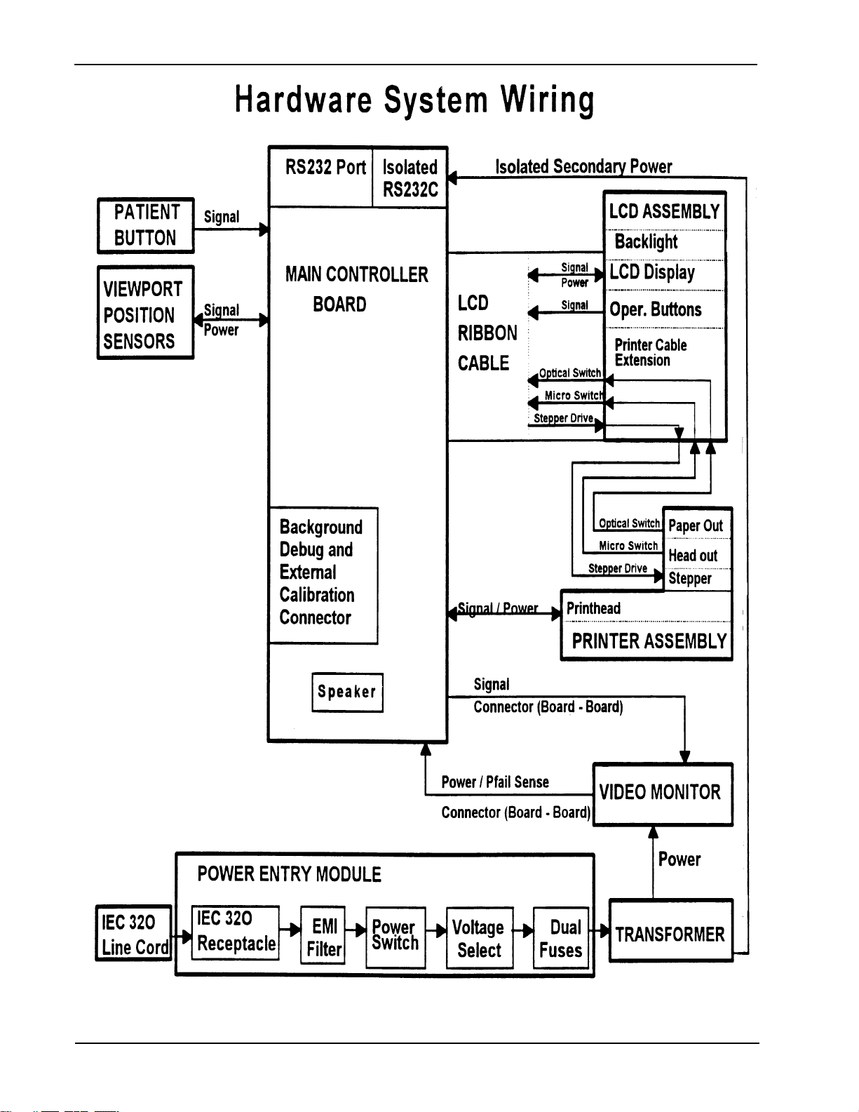
Hardware System Wiring Block Diagram 6
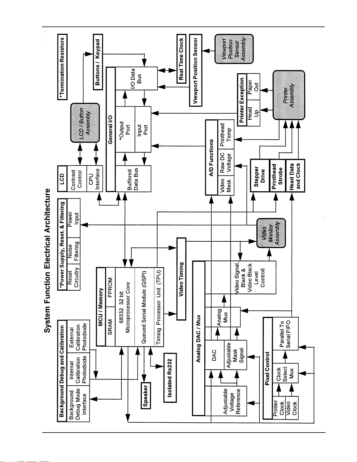
System Function Electrical Architecture Block Diagram 7
Section 2: Service
Incoming Inspection 1
Tools Required for Service and Factory Calibration and Software Uploading 2
Factory Calibration for Software Version 1.20 or Higher 3
Loading Software for FDT 5
Final Testing 6
Hypot Ground Continuity, and Leakage Current Testing 11
Important Shipping Information 12
Calibration Limits Information 13
Product Updates 15
Section 3: Troubleshooting
Chief Complaint, Cause, Corrective Action 1
Power On Self Test (P.O.S.T.) Status Table 3
FDT Terminology 4
FDT Error Messages 5
Section 4: Disassembly and Repair
4.1 Removal of Rear Housing/LCD Assembly 1
4.2 Replacement of Rear Housing/LCD Assembly 3
4.3 Disassembly of Optics 3
4.4 Assembly of Optics 11
4.5 Removal of Printer 15
4.6 Installing Printer 16
4.7 Removal of MCU/ PCB 17
4.8 Installing MCU/PCB 19
4.9 Installing a Replacement Chassis/Monitor Assembly 20
4.10 Removal of Transformer 20
4.11 Installing Transformer 21
4.12 Removal of PRB Jack 21
4.13 Replacement of PRB Jack 21
4.14 Removal of Power Entry Module 21
4.15 Replacement of Power Entry Module 22
4.16 Removal of Visor Position Sensor (VPS) 22
4.17 Replacement of VPS 22
4.18 Removal of Internal Photodetector (IP) 23
4.19 Replacement of IP / PCB 23
4.20 Removal of LCD Module/Keypad 23
SERVICE MANUAL 112120 REV. B
HUMPHREY FDT VISUAL FIELD INSTRUMENT iii
Page 6

Section 4: Disassembly and Repair Cont’d
4.21 Replacement of LCD Module/Keypad 24
4.22 Removal of Visor Pad 24
4.23 Installing Visor Pad 25
4.24 Removal of Acrylic Lenses and Optics Tube Window 25
4.25 Installing Acrylic Lenses and Optics Tube Window 26
Section 5: Interconnect Diagrams 112119
Section 6: Repair Parts
Key to Repair Parts List 1
Parts List (3 pages) 2
Section 7: FDT Assembly Drawing 112000 Domestic 3 sheets
FDT Assembly Drawing 112200 International (CE) 4 sheets
Section 8: Schematics 112106, 112091 , 112037
Section 9: CE Model Disassembly and Repair
9.1 Removal of Rear Housing/LCD Assembly 1
9.2 Replacement of Rear Housing/LCD Assembly 3
9.3 Disassembly of Optics 3
9.4 Assembly of Optics 10
9.5 Removal of Printer 14
9.6 Installing Printer 15
9.7 Removal of MCU/ PCB 16
9.8 Installing MCU/PCB 19
9.9 Installing a Replacement Chassis/Monitor Assembly 20
9.10 Removal of Transformer 20
9.11 Installing Transformer 21
9.12 Removal of PRB Jack 21
9.13 Replacement of PRB Jack 21
9.14 Removal of Power Entry Module 21
9.15 Replacement of Power Entry Module 22
9.16 Removal of Visor Position Sensor Board (VPS) 22
9.17 Replacement of VPS 22
9.18 Removal of Internal Photodetector (IP) 23
9.19 Replacement of IP 23
9.20 Removal of LCD Module/Keypad 23
9.21 Replacement of LCD Module/Keypad 24
9.22 Removal of Visor Pad 24
9.23 Installing Visor Pad 25
9.24 Removal of Acrylic Lenses and Optics Tube Window 25
9.25 Installing Acrylic Lenses and Optics Tube Window 26
iv HUMPHREY FDT VISUAL FIELD INSTRUMENT
SERVICE MANUAL 112120 REV. B
Page 7

Section 1 - General Information
The 710 Series FDT Visual Field Instrument
utilizes Frequency Doubling Technology (FDT).
Various preprogrammed patterns of flickering black
and white vertical bars are presented to the patient on a video screen. Each patient is tested on
the degree of contrast between the black and
white bars which enables them to see each pattern.
The Frequency Doubling stimulus taps into a
select subset of retinal ganglion cells that have
been observed to die in early glaucoma patients.
Because the stimulus is selective only to this
subset of cells, the test is accurate and rapid.
About The 710 Series FDT
Visual Field Instrument
SERVICE MANUAL 112120 REV. B
HUMPHREY FDT VISUAL FIELD INSTRUMENT 1
Page 8

Section 1 - General Information
Help Information:
All service and repairs must be performed by authorized
Humphrey Instruments personnel or agents, using genuine
replacement parts. Failure to do so will invalidate the prod-
uct warranty.
Read and understand all safety warnings and service
notes printed in this Service Manual and the User’s
Guide. If in doubt about any precaution or procedure,
call Humphrey Instruments Customer Service phone
number below.
For Phone Help, call Humphrey Instruments Customer Service at: 800-341-6968
The part and serial numbers are located on the bottom of
the unit.
Troubleshooting assistance is contained in Section 3 of this
manual. Troubleshooting is limited to board level replacement and not board component replacement.
Please read and understand FDT User’s Guide #112098,
a copy of which may be obtained by calling Humphrey Instruments Customer Service Department at the toll free 800
number above.
2 HUMPHREY FDT VISUAL FIELD INSTRUMENT
SERVICE MANUAL 112120 REV. B
Page 9
Section 1 - General Information
Read Important Safety Information in User’s Guide.
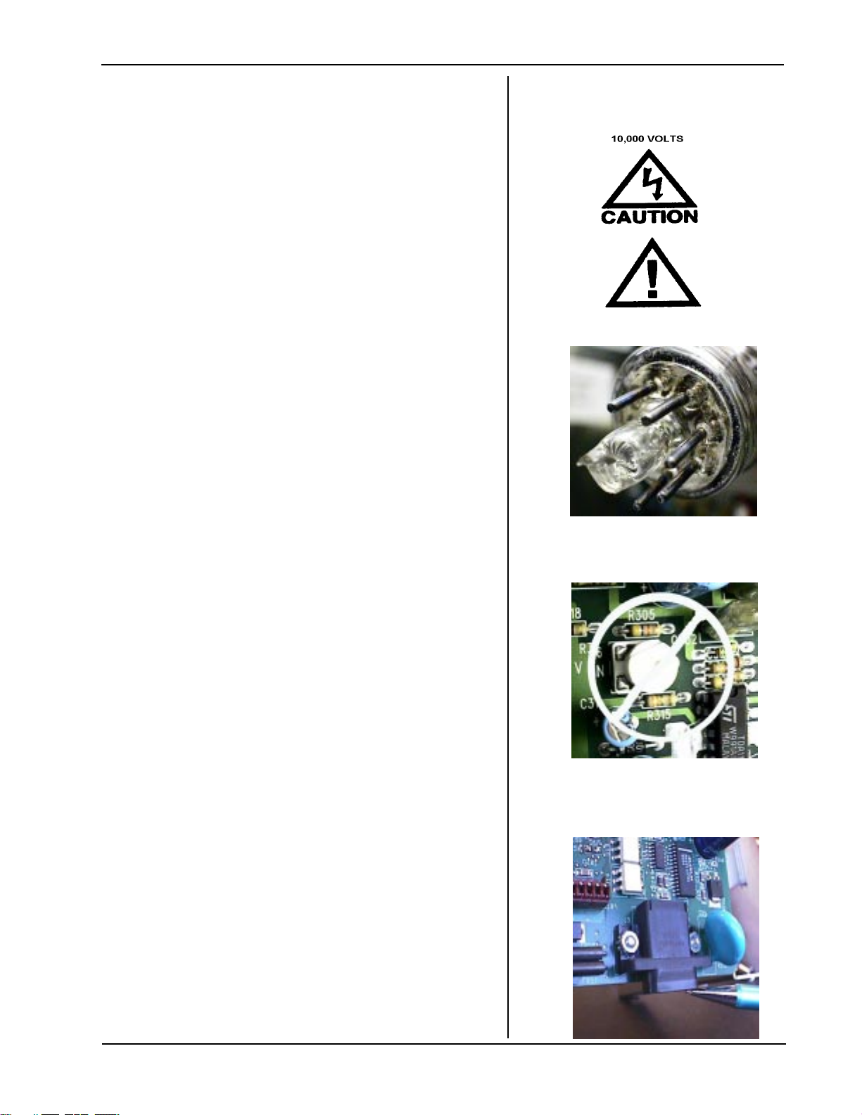
EXERCISE EXTREME CAUTION WHEN
SERVICING THE FDT! THE MONITOR ASSEMBLY
OPERATES ON APPROXIMATELY 10,000 VOLTS!
Do not remove the plug from the end of the CRT
exposing sharp glass process tube. This can
cause cuts! (Photo 1 at right.)
Disconnect FDT from Mains when disassembling.
Clean as recommended in Users Guide.
Follow ESD precautions during service.
Test repaired FDT units at 115v and 230v prior to
returning them to customers.
Support the FDT by holding under the base to protect
the upper optics section from stress.
Important Safety Warnings
and Service Notes
Photo 1
Please DO NOT adjust pots on the monitor board.
The video monitor is a non-standard design and
because of this, there are no field monitor or video
service adjustments. Video adjustments can only be
performed by the monitor manufacturer with special
equipment. Unauthorized adjustments may result
in clinically invalid results without obvious
indications of any malfunction. (Photo 2 at right)
Tighten fasteners carefully. Refer to drawing
#112000 in this manual for recommended fastener
torque specifications.
Put a calibration cap (see bubble number 90 on
drawing 112000) on the optics tube assembly during
servicing to protect optics tube window.
The RS232 connector housing of the MCU PCB
projects below the bottom of the MCU PCB (Photo 3
at right). Do not stand the chassis monitor assembly
on this connector. Put the chassis monitor assembly
on its back between repair steps.
Photo 2
Photo 3
Always install latest revision software when installing
a new MCU/PCB. Call Humphrey Customer Service.
See Section 2 Pg. 4 for details.
SERVICE MANUAL 112120 REV. B
HUMPHREY FDT VISUAL FIELD INSTRUMENT 3
Page 10
Section 1 - General Information
Important Safety Warnings
and Service Notes
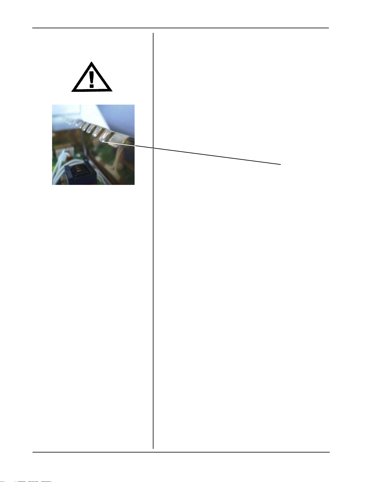
Photo 4
Copper ESD shields may have sharp edges.
Exercise caution to avoid cuts!
4 HUMPHREY FDT VISUAL FIELD INSTRUMENT
SERVICE MANUAL 112120 REV. B
Page 11
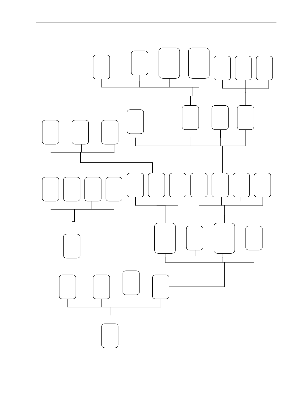
Section 1 - General Information
FDT MAIN
ENTER
PATIENT
AGE
UTILITIES
MENU
**ADVANCE
PAPER
RUN DEMO.
RUN
PATIENT
TESTS
SET-UP
INSTRUMENT
MENU
RUN SELF
CAL.
INSTRUMENT
TESTS MENU
ABOUT FDT
RUN
SCREENING
C-20 TEST
RUN FULL
THRESHOLD
C-20 TEST
RUN FULL
THRESHOLD
N-30 TEST
SKIP EYE
SET CLOCK
MENU
SET-UP
OPTIONS
MENU
PRINT
SET-UP
REPORT
TEST
INPUTS
TEST
OUTPUTS
TEST
SERIAL
PORT
SELECT
LANGUAGE
OPTIONS
RESET TO
DEFAULTS
TEST LCD
TEST VIDEO
MENU
TEST
SPEAKER
TEST
PRINTER
MENU
AMBIENT
LIGHT
CHECK
CALIBRATION
CHECK
FACTORY
CALIBRATION
RUN
PRINTOUT
TEST
ADVANCE
PAPER
TEST VIDEO
SYSTEM
TEST A/D
CIRCUITRY
+10 years
-10 years
+ 1 year
ACCEPT SETTING
BUTTONS
PRB
VIEWPORT
POS
CHECKERBOARD
BLANK SCREEN
FULL SCREEN
** AFTER TEST PERFORMED, WILL READ
LAST PATIENT RESULTS
DIXIE PATTERN
LCD MEMORY
BACKLIGHT (ON/OFF)
Printer
Status
SERVICE MANUAL 112120 REV. B
HUMPHREY FDT VISUAL FIELD INSTRUMENT 5
Page 12
Section 1 - General Information
6 HUMPHREY FDT VISUAL FIELD INSTRUMENT
SERVICE MANUAL 112120 REV. B
Page 13
Section 1 - General Information
SERVICE MANUAL 112120 REV. B
HUMPHREY FDT VISUAL FIELD INSTRUMENT 7
Page 14

Page 15

Section 2 - Service
When an FDT unit is returned, check:
1) Physical condition of packaging.
2) Physical condition of unit.
3) List any accessories with unit, for example:
power cord
Patient Response Button (PRB)
calibration cap
dust cover
computer interface cable
Incoming Inspection
4) Perform “PRINT SET-UP REPORT” if
possible, and keep for reference.
5) Perform Cleaning/Disinfection per instuctions
in User’s Guide, Section 4, Maintenance.
SERVICE MANUAL 112120 REV. B
HUMPHREY FDT VISUAL FIELD INSTRUMENT 1
Page 16
Section 2 - Service
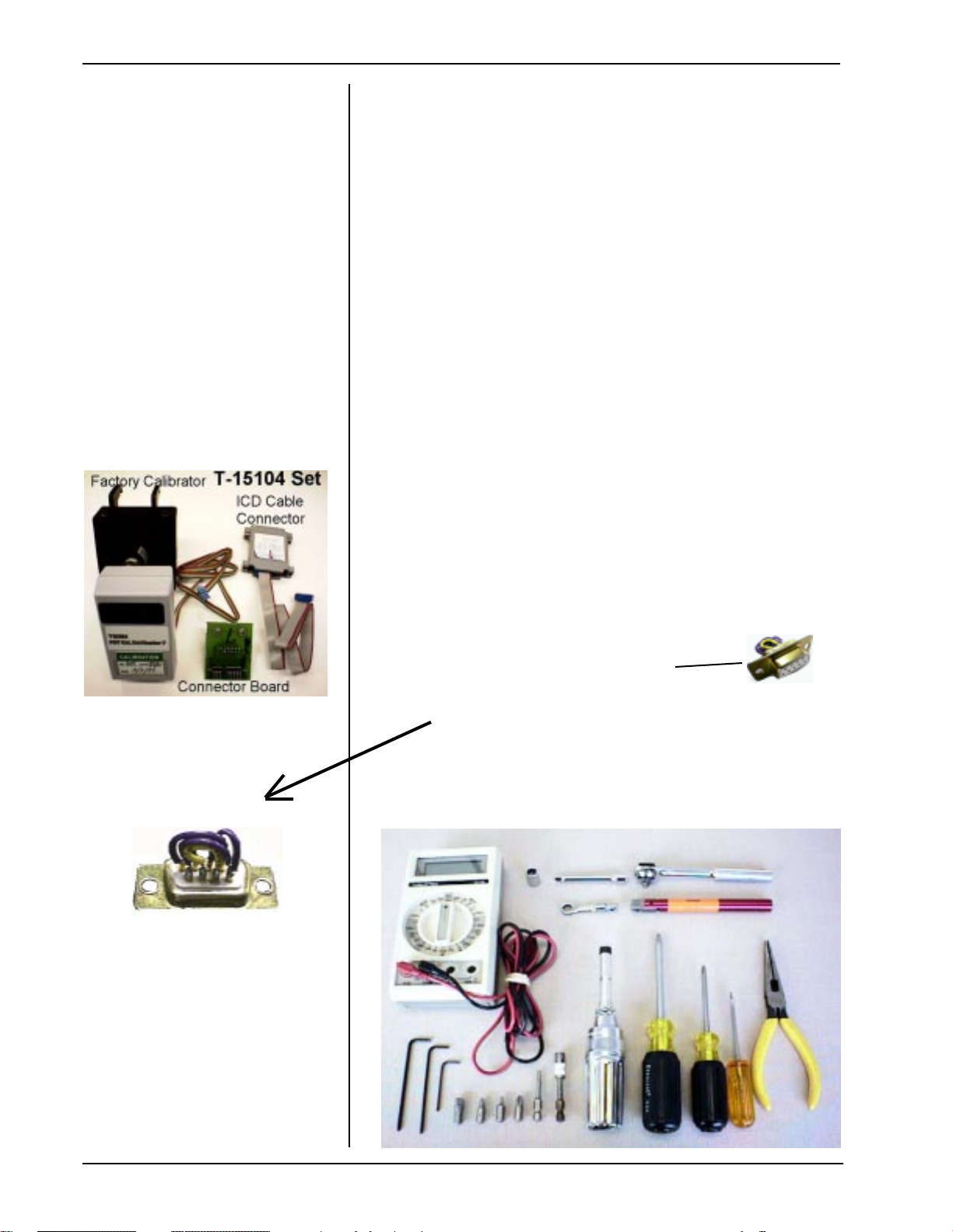
Tools Required for Service
Factory Calibration
and Software
Uploading
Photo 1
#1 Flathead screwdriver - 2” length
#1 Phillips screwdriver - 4” length
#2 Philips screwdriver - 4” length
1/4” drive ratchet with 1/4” extender
11/32” socket
3/32” hex key
7/64” hex key
Adjustable torque driver - 2 - 14 in/lbs range
Bits for Torque Driver:
#1 Phillips
#2 Phillips
3/32” hex
7/64” hex
1/4” square to hex adapter
Torque Wrench - Adjustable 2 - 14 in/lbs range
Torque Handle: Mountz 06-8002 TB1H 12-21
in/lb or equivalent.
Torque Handle Box Wrench accessory:
Mountz 068127 Box Head - 11/32”
Photo 1b
T15145 - for PRB connector
T15104 - Calibrator and Software Floppy Disc
(see Photo 1 at left)
T15810- Serial Port Tester
(can be made with a standard DB 9 female with
these connections: Pins 1,4,6,9 common
Pins 2,3 common
Pins 6,8 common
Digital volt meter ( three plus range)
Needle nose pliers
Photo 2
2 HUMPHREY FDT VISUAL FIELD INSTRUMENT
SERVICE MANUAL 112120 REV. B
Page 17
Section 2 - Service
Upgrade recommendation: Upgrade all re-
turned FDT’s with Software Version 2.10. Perform
Factory Calibration Process.
Start Factory Calibration Process:
1 Turn FDT unit OFF.
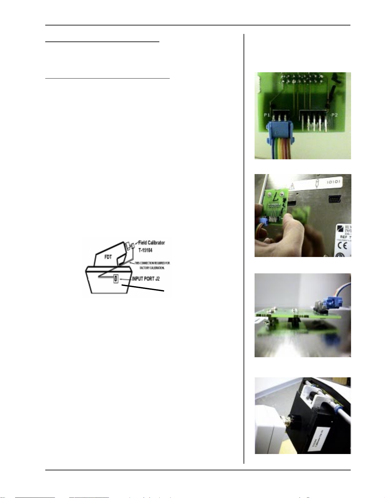
2 Connect the wire from the T-15102 Factory
Calibrator to connector board as shown in Photo 3.
Wires must exit from top of connector as shown.
3 Remove Visor/Browrest (Sect 4 or 9 for CE FDT)
Factory Calibration
for Software Version.
1.20 or higher
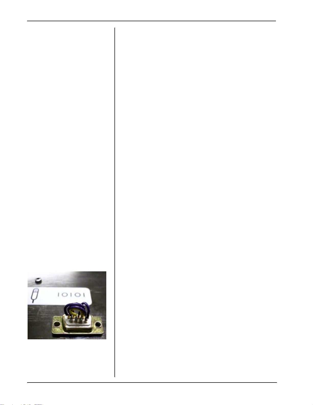
4 Tilt FDT on its side to remove label over Calibration/
Software loading port J2.
5 Align threaded studs of connector board with the two
holes near port J2 as shown in Photo 4.
6 Insert T 15102 into port J2 as shown in Photo 5.
Hookup should be as shown in Figure 1 below.
Fig. 1
connector board
T 15102
7 Position the FDT in upright position and place
calibrator onto the slide bracket . See Photo 6
Note: Place calibrator on viewport tightly to prevent
light from entering the calibrator housing.
Photo 3
Photo 4
8 Turn the FDT ON and view the menu on the LCD:
a) Press button next to UTILITIES MENU
b) Press button next to INSTRUMENT TEST MENU
c) Press button next to TEST OUTPUTS
d) Press button next to TEST VIDEO MENU
e) Press button next to FACTORY CALIBRATION
NOTE: Unit can be calibrated with PC utility Calibrat
through the FDT computer interface. Refer to the Calibrate utility for more information.
9 Press any button to indicate that you have placed
the factory calibrator on the view port.
SERVICE MANUAL 112120 REV. B
HUMPHREY FDT VISUAL FIELD INSTRUMENT 3
Photo 5
Photo 6
Page 18

Section 2 - Service
Factory Calibration
for Software Version.
1.20 or higher
(continued)
10 Press any button to start the Factory Calibration
calibration process. Duration : less than 1minute.
NOTE: Self-Calibrate is automatically performed
during Factory Calibration in Version 2.10
11 Turn the FDT OFF and remove calibrator from
slide bracket.
12 Remove T-15102 connector board from Port J2 on
bottom of FDT. Install a new label part # 112066
over J2 port.
13 Turn FDT ON and view the menu on the FDT LCD:
a) Press the green button until the UTILITIES
Menu is reached.
b) Put the black calibration cap on the viewport.
c) Press the button next to RUN SELF
CALIBRATION. (Process time: 2 - 3 min.)
Note: A progress indicator will display on the LCD. It
will indicate what percentage of the calibration is
complete. The unit will indicate when calibration is
complete and return to UTILITIES MENU.
14 Now perform a Calibration check:
a) Press button next to INSTRUMENT TEST
MENU.
b) Press button next to TEST OUTPUTS
c) Press button next to TEST VIDEO MENU
d) Press button next to CALIBRATION CHECK
Note: The meter will indicate that the FDT is fully
calibrated.
15 Press any button to continue.
16 Press the green button 4 times or until FDT MAIN
MENU is reached.
17 Install the visor/browrest with the 4 black hex socket
head cap screws as shown in Section 4.
Note: See Calibration Limits/Parameters Tables
4 HUMPHREY FDT VISUAL FIELD INSTRUMENT
in this section.
(End of Factory Calibration Process)
SERVICE MANUAL 112120 REV. B
Page 19
Section 2 - Service
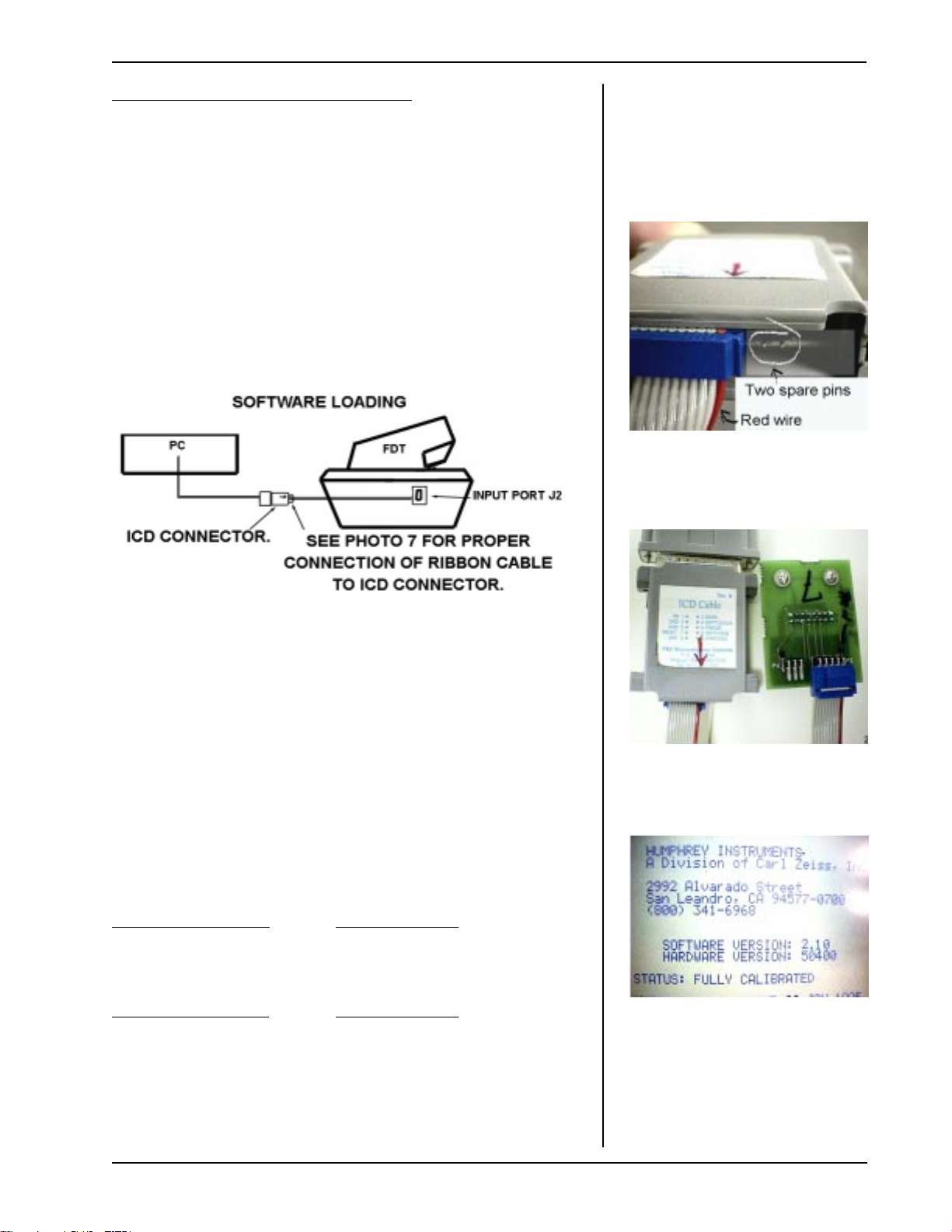
Start Software Loading Process:
1 Connect the ribbon cable to the ICD Cable
connector as shown in Photo 7 at right.
Note: a) 2 Pins at right are not used
b) Align the red wire of the ribbon cable
with the red arrow on ICD connector.
2 Connect the ribbon cable to the connector board as
shown in Photo 8.
3 Connect ICD connector to the PC Parallel Port .
See Figure 2 below.
Loading Software for FDT
Note: FDT software is not
Mac compatible.
Photo 7
Figure 2
4 Insert T 15102 into port J2 as shown in Photo 5
and follow software loading instructions displayed
on the PC when running FDT Software Installation
Program.
Note: Whenever installing a new MCU/PCB and
loading highest revision software, verify proper
hardware (marked on MCU/PCB) version using
“ABOUT FDT”. LCD Screen will display
software/hardware data. See Photo 9
Software Version: Release Date:
Ver. 1.20 July 1997
Ver. 2.10 October 1997
Hardware Version: Release Date:
MCU/PCB Rev 503 August 1997
MCU/PCB Rev 504 September 1997
Photo 8
Photo 9 FDT LCD Screen
Note: See Product Updates in this section.
SERVICE MANUAL 112120 REV. B
HUMPHREY FDT VISUAL FIELD INSTRUMENT 5
Page 20

Section 2 - Service
Final Testing
(page 1 of 6)
Note: Follow this final testing process to verify
correct operation after the FDT has been serviced.
1. Calibration
Follow instructions in the calibration section of
manual.
2. 230 Volt testing
Remove fuse block. Replace the 115v fuses
(.315A) with those recommended for
230v.(.160A)
Place fuse block back into unit so the 230v
shows. Plug unit into a 230v line and turn unit
on. After approximately 10-15 seconds the unit
should go through a series of beeps and the
FDT Main menu should appear. After this test is
done, turn off unit, remove power and replace
the fuses with the 115V (.315A) ones. Be sure
that the115V shows in the fuse drawer.
3. Operational testing
3.1 Plug in PRB.
3.2 Turn unit on. After approximately 10-15
seconds the unit will complete self
diagnostics and emit two double beeps.
The FDT main menu will appear.
3.3 Press the button next to UTILITIES
MENU.
3.3.1 Check the intensity adjustment.
a) Press the button pointing
b) Press the button pointing
c) Use both buttons as needed
downward. The LCD
contrast will decrease.
upward. The LCD contrast
will increase.
to return to usable LCD
contrast.
6 HUMPHREY FDT VISUAL FIELD INSTRUMENT
SERVICE MANUAL 112120 REV. B
Page 21

Section 2 - Service
3.3.2 Press the button next to ABOUT
3.3.3 Press the green button on the
3.4 Press the button to the left of
INSTRUMENT TESTS MENU.
3.4.1 Press the button next to
FDT. The screen will indicate that
the unit is fully calibrated and show
the software revision. Make
sure that it has the latest revision
software.
bottom left. This should bring you
back to the UTILITIES MENU.
TEST INPUTS.
a) Press each of the 4 upper
left buttons. When each
buttons is pressed, the
word PRESS to the right of
the button will change to a
PRESSED highlighted.
Release the button. PRESS
will reappear unhighlighted.
b) Move the visor to the three
different positions - left,
middle and right (patients
side). The Eye test posi-
tion on the right hand side
of the display will change
state to indicate the current
eye test position.
c) The Patient button will
indicate NOT PRESSED.
Press the PRB and it
will report a highlighted
PRESSED.
d) Unplug the PRB plug from
the PRB jack. The Patient
Button status will indicate:
Not connected. Plug the
PRB plug into the PRB jack.
Final Testing
(page 2 of 6)
3.4.2 Press the green button on the
bottom left to return to
INSTRUMENT TESTS MENU.
SERVICE MANUAL 112120 REV. B
HUMPHREY FDT VISUAL FIELD INSTRUMENT 7
Page 22

Section 2 - Service
Final Testing
(page 3 of 6)
3.5 Press the button next to TEST OUTPUTS.
3.5.1 Press the button next to TEST
LCD.
a) Observe highlighted test
option on screen.
b) Press button next to RUN
TEST. The LCD will reflect
state of the highlighted test
option.
c) Press any button to exit
present LCD test.
d) Press button next to NEXT
CHOICE to change test
option.
e) Perform the above steps for
the CHECKERBOARD,
BLANK SCREEN, FULL
SCREEN, AND DIXIE
PATTERN options.
f) Press button next to NEXT
CHOICE to highlight LCD
MEMORY TEST.
g) Press button next to RUN
TEST. The display will be;
Testing LCD memory and
change to LCD memory
passed. Press any button
to exit test.
h) Press button next to NEXT
CHOICE to highlight the
BACKLIGHT option.
i) Press button next to RUN
TEST a number of times
and observe the LCD
screen. The backlight
should toggle on and off.
Make sure the Backlight is
on before exiting this test.
j) Press the green button to
return to OUTPUT TESTS.
8 HUMPHREY FDT VISUAL FIELD INSTRUMENT
SERVICE MANUAL 112120 REV. B
Page 23

Section 2 - Service
3.5.2 Press the button next to TEST
3.5.3 Press the button next to AMBIENT
VIDEO MENU.
a) Press the button next to
TEST VIDEO SYSTEM.
b) Look into the patient viewing
area. A large flashing circle
exhibiting the Model 710
Seriesgrating pattern in the
center of the viewing area
will be visible.
c) Press the Green button to
return to TEST VIDEO
MENU.
LIGHT CHECK.
a) There may be a short time
for monitor warm up.
b) With the calibration cap on,
the pointer will be in the
dark range.
c) Remove the calibration cap.
The pointer will rise to
the light or bright range,
depending upon the intensity of the room lighting.
d) Put the calibration cap back
on and press the green
button to return to TEST
VIDEO MENU.
Final Testing
(page 4 of 6)
3.5.4 Put Calibration cap on. Press
button next to CALIBRATION
CHECK.
NOTE:Calibration will be denied if cap is off and room
light level is too high.
a) The pointer should be in the
fully calibrated range.
b) Do not press the factory
calibration option. If this
option is accidentally
chosen, the unit will detect that a calibrator is not
attached and warn user.
c) Press the green button twice
to return to OUTPUT
TESTS MENU.
SERVICE MANUAL 112120 REV. B
HUMPHREY FDT VISUAL FIELD INSTRUMENT 9
Page 24
Section 2 - Service
Final Testing
(page 5 of 6)
Final Testing
3.6 Press the button next to TEST SPEAKER.
3.6.1 There will be increasing tones.
3.7 Press the button next to TEST PRINTER
MENU.
3.7.1 The TEST PRINTER MENU will be
displayed. Press the button next to
RUN PRINTOUT TEST. The FDT
will print out a series of patterns
and instrument data.
3.7.2 Press the button next to ADVANCE
PAPER. The paper will
advance about 1-2 inches beyond
the slot in the paper door.
3.7.3 Press the button next to PRINTER
STATUS. “PRINTER OK”
message will appear.
Photo 10
3.7.4 Press the green button 3 times to
return to INSTRUMENT TESTS
MENU.
3.8 Press the button next to TEST SERIAL
PORT.
3.8.1 Press any of top four buttons to
execute test.
3.8.2 Both the data transfer and hand
shaking test should fail.
3.8.3 Press the green button to return to
INSTRUMENT TESTS MENU.
3.8.4 Place T-15810 into the serial port
on bottom of unit. See Photo 10.
3.8.5 Press the button next to TEST
SERIAL PORT.
a) Press any of top four but-
tons to execute tests.
b) LCD will display:
DATA TRANFER PASSED
HANDSHAKING PASSED
10 HUMPHREY FDT VISUAL FIELD INSTRUMENT
SERVICE MANUAL 112120 REV. B
Page 25

Section 2 - Service
3.8.6 Press the green button twice to
3.8.7 Remove T-15810.
3.9 Press the button next to A/D CIRCUITRY.
3.9.1 A reading will come up for
3.10 Perform a screening test to check unit
operation.
3.11 Turn unit off.
4. Agency testing
4.1 Hypot
Testing at 1500VAC for one second.
Apply the voltage between primary wiring
(supply terminals connected together)
and accessible dead metal parts without
breakdown indication.
4.2 Ground continuity
Total resistance of the product shall not
exceed 0.2 ohms (2.0VDC). The test will
be conducted using a 10 amp DC current
source with a no load voltage no greater
than 6.0VDC for five seconds. Measure
ment will be taken from the grounding pin
of the power supply cord to the accessible
metal part of the product.
4.3 Leakage current
The leakage current measured from any
exposed grounded metal parts to the
grounding pin of the power supply cord
shall not exceed 100 microamps, AC
RMS (95.5MVAC RMS) with input voltage
set to 120VAC, 60HZ or 240VAC, 50HZ.
return to INSTRUMENT TESTS
MENU.
Mean gray and printhead tem perature. If the unit fails this test
a malfunction error will appear.
Final Testing
(Page 6 jof 6)
Hypot, Ground Continuity,
and Leakage Current
Testing
(For In-House use only.)
If a FTD fails any test in this section, set it aside for
troubleshooting and repair. When the FDT is repaired and passes all the tests, place a label over
the calibration port.
SERVICE MANUAL 112120 REV. B
HUMPHREY FDT VISUAL FIELD INSTRUMENT 11
Page 26
Section 2 - Service
Important Shipping
Information
Paper roll foam prevents
un-winding during ship-
ping
Note: Install a new roll of paper.
Install the paper roll foam before
packing the unit for shipping. See
photo at left. This foam strip (called
foam shipping wedge in User’s Guide)
prevents the paper roll from unwinding
during shipping.
Return all of the customer’s
accessories.
12 HUMPHREY FDT VISUAL FIELD INSTRUMENT
SERVICE MANUAL 112120 REV. B
Page 27

Section 2 - Service
Calibration Limits Information
Table A:Calibration Parameters Printed on the System Status Report
Parameter Nominal SW
Limit
Expected
Min
Min
SCAN LINE
(internal)
GAMMA *2.35 1.0 *2.2 *2.5 <3.0
REFERENCE
POT
INTERNAL
TARGET
DC OFFSET 30 0 *10 *50 1023
INTERNAL
PEAK
*90 6 *60 *110 235
NA 0
*2250 0 *1500 *3000 4095
Internal
Target 0
*15
(new CRT)
Internal
Target - 40
Expected
Max
*60
(new CRT)
Internal
Target + 40
SW
Limit
Max
255
4095
Comments/Description F.C.** S.F.***
Reflects mechanical alignment of
photodetector to CRT.
CRT response correction
exponent.
Adjusts for CRT aging.
( *150 expected max on old CRT)
Absolute value read from Internal
photodetector ADC when CRT is
200 c/m^2.
DC offset on internal
photodetector signal.
Absolute value read from Internal
photodetector ADC when CRT is
as close to 200 c/m^2 as the
reference pot can adjust.
X
X
X
* These numbers are approximate and have not been verified by statistical tracking.
** Adjusted during Factory Calibration
***Adjusted during Self Calibration
X
X
Table B:Calibration Parameters to LCD and Serial Port: Factory Calibration
Message Expected Limits Comment
INTERNAL PEAK NA This is a transeint message that reports DAC settings.
External
Photo Sensor Stop
Line
External Photosensor 3000+/- 20
DC OFFSET Same as in table (A) above. Same as in table (A) above.
Internal Photosensor
Stop Line
Internal Photosensor
* These numbers are approximate and have not been verified by statistical tracking.
SERVICE MANUAL 112120 REV. B
*40 min, *70 nom, *100 max Two passes: Second pass should be within 16 of first.
External target 3000 = 200c/m^2. This is how close the
reference pot gets to 200 c/m^2.
Same as SCAN LINE in table
(A) above.
Same as INTERNAL TARGET
in table (A) above.
Same as in table (A) above.
Same as in table (A) above.
HUMPHREY FDT VISUAL FIELD INSTRUMENT 13
Page 28

Section 2 - Service
Calibration Limits Information
Table C:Calibration Parameters to LCD and Serial Port: Self Calibration
Message Expected Limits Comment
Internal Photosensor
Ambient Light
REFERENCE POT
Dynamic Range 82 min allowed by SW (50:1) Full screen brightness to zero screen brightness ratio.
Gamma Factor
Linearity
Same as INTERNAL TARGET
in table (A) above.
82 max allowed by SW
(2% of full brightness)
Same as REFERENCE POT in
table (A) above.
Same as in GAMMA
CORRECTION in table (A) above.
Second Column is limited to 120
(3% deviation from straight line)
Same as in table (A) above.
Keep unit as dark as possible. If this fails in dark, unit
is broken, or DC offset is bad - Factory calibration
needed.
Same as in table (A) above.
Same as in table (A) above.
First column is linear ramp target value written to
DAC. Second column is photodetector reading
deviation from the linear ramp. Scale is 127 - 4095.
* These numbers are approximate and have not been verified by statistical tracking.
14 HUMPHREY FDT VISUAL FIELD INSTRUMENT SERVICE MANUAL 112120 REV. B
Page 29

Section 2 - Service
Product Updates
Effectivity S/N Cut-In
7/97 S#9700200
8/97 S#9701000
8/29/97 ~S#9701145 Color changes of housings:cream to gray.
9/11/97 S#9701199
9/15/97 ~S#9701210
10/3/97 S#9701294 SW Version 2.10 (Language translations)
DOMESTIC FDT UNITS :
Description of Changes for 00710-11
Sales Demo Units (all S#>9700199 and
9701000) . Monitor needs rework at some time
to extend calibration life.
SW Version 8.30.
HW Version 50300 (MCU PCB 112037-503)
Initial Production units for end users (all
S#>9701000). SW Version 1.20.
HW Version 50300 (MCU PCB 112037-503)
HW version 50400 (MCU PCB 112037-504 for
CE)
Calibration Caps (pn112078-1) Started shipping
with instruments.
Effectivity S/N Cut-In
9/97 S#9731000
S#9731025
(also
10/3/97
S#9731019
and
S#9731023
are Ver. 2.10
SERVICE MANUAL 112120 REV. B
CE INTERNATIONAL FDT UNITS :
Description of Changes for 00710-X1 (X=2-9)
Note:Domestic S#'s have a 0 in the 3rd digit,
International S#'s have a 3)
Initial International Production units (all
S#'s>9731000)
SW Version 1.20.
HW version 50400 (MCU PCB 112037-504 for CE)
SW Version 2.10 (language translations)
HUMPHREY FDT VISUAL FIELD INSTRUMENT 15
Page 30

Page 31

3 Troubleshooting
Note: Install Latest Revision Software with New MCU/PCB
Chief Complaint Cause Corrective Action
Does not power up.
No LCD backlight or text
(with high or low contrast)
LCD has backlight but no
text
LCD has text but no
backlight
a) Improper fuse drawer
setting.
b) Blown fuse(s) Replace fuses. No
c) Improperly wired power
entry module.
d) Defective transformer Replace transformer No
a) Loose connections,
damaged cables.
b) Failed LCD module Replace LCD No
c) MCU PCB defective Replace MCU PCB Yes
a) Failed LCD contrast
keypad
a) Loose connections Restore connections No
b) Defective LCD module Replace LCD module No
Correct fuse drawer No
Restore correct connections No
Check connection. No
Clean or replace keypad No
Factory Calibration
Required
PRB not working
(patient response button)
Unit not sure of visor
position
Unit will not calibrate using
the calbrator
c) Defective MCU PCB Replace MCU PCB Yes
a) Improper/Defective
connection with unit
b) Defective PRB Replace PRB No
c) Defective PRB
connector
d) Defective MCU PCB Replace MCU PCB Yes
a) Defective VPS PCB Replace VPS PCB No
b) Reflective labels
missing
c) Defective MCU PCB Replace MCU PCB Yes
a) Defective calibrator
b) Defective internal light
meter.
Check connections of PRB
connector and MCU PCB
Replace PRB connector No
Replace labels No
Check calibrator on another
unit. (If calibrator is defective,
send in for calibration.)
Replace internal light meter
(PCB)
FDT does not require cal.,
but calibrator does need
to be calibrated at factory.
No
Yes
c) Defective Monitor
Assembly.
d) Defective MCU PCB Replace MCU PCB Yes
Replace Monitor Assemlby Yes
See next page for important note when installing a new MCU/PCB.
SERVICE MANUAL 112120 REV. B
HUMPHREY FDT VISUAL FIELD INSTRUMENT 1
Page 32

3 Troubleshooting
Note: Install Latest Revision Software with New MCU/PCB
Chief Complaint Cause Corrective Action
No printing on paper a) Incorrectly installed paper.
b) Defective paper Replace paper No
c) Incorrect paper Replace paper No
d) Defective printer Replace printer No
e) Wiring problems
f) Defective MCU PCB Replace MCU PCB Yes
RS 232 Port Malfunctions
Does not advance paper
a) No output (8.5Vac) from
purple transformer wires.
b) Defective MCU PCB.
Broken RS232 connector.
(Bent pins, bad solder joint.)
a) Loose connectors,
damaged cables.
b) Defective printer motor. Replace printer No
Install paper correctly referen cing Users' Guide.
Correct wiring or replace
printer.
Replace transformer No
Replace MCU PCB Yes
Restore connection or replace
cables .
Factory Calibration
Required
No
No
No
Optics tube window
damaged
Spots on optics a) Debris on lens Clean optics
Install new optics tube window. Yes
(If optics are
disassembled, Factory
Calibration is required due
to possible change in
allignment of Internal
Photodetector.)
Important Note when installing a new MCU/PCB:
For new MCU/PCB’s, use the PC utility SETNVRAM to initialize NVRAM and to load
the following:
PATIENT TESTS
CRT ACTIVE TIME
UNIT ON TIME
Calibration Count
S/N (Serial Number)
HW VER (Hardware Version)
MODEL NUMBER
ODOMETER SEG
Yes
REFER TO THE PC UTILITY SETNVRAM FOR MORE INFORMATION.
2 HUMPHREY FDT VISUAL FIELD INSTRUMENT SERVICE MANUAL 112120 REV. B
Page 33

3 Troubleshooting
A “P.O.S.T.” test is automatically programmed to occur
each time the FDT unit is switched to ON. Two double
“beeps” will be made by the unit near the end of the test.
Four conditions can occur when the unit Powers UP:
Fully Calibrated, Needs Calibration/Return Unit to Factory,
Needs Self Calibration, and Hardware Failure.
These are shown in the POST table below:
Printout
STATUS and
Message
ABOUT FDT:
Status Code
found in SET
NVRAM utility
RUN STATUS "
"
Display on
LCD
Cause(s) of Message(s) Next Step
Power On Self Test
(P.O.S.T.) Status
Table
FULLY
CALIBRATED
NEEDS
CALIBRATION
RETURN UNIT
TO FACTORY
NEEDS SELF
CALIBRATION
HARDWARE
FAILURE,
RETURN UNIT
TO FACTORY
"0" Main Menu
"1" Utilities Menu
CALIBRATION"
"2"
"3" Utilities Menu
*NOTE:
FOR VER
2.10
SELF
CALIBRATION
AUTOMATIC ALLY
FACTORY
FOLL OW
CALIBRATION
(NOTE: Depress
green button 2 times
to go to UTILITY
MENU to print out a
.
WILL
"SYSTEM
FAILURE
NEEDS
report.)
1.Unit passed internal
calibration.
1.Cancelled or failed factory
calibration.
2.Start factory calibration.
3.Fails loading of default values
to nvram.
1.Fails gamma checksum test.
2.Fails cal check.
3.Fails mean calc
4.Fails gamma table check.
5.Odom seg filled
6.Passed factory calibration.
7.Fail or cancel self calibration.
8.Fails nvram checksum.
1.Fails mean pot test.
2.Fails head temp circuit.
Unit is O.K.
Calibration
Calibration
Calibration
Perform
Factory
Perform
Self
Perform
Factory
Bit: Test:
0 RAM
1 ROM
2 RTC INITIALIZED
3 RTC WORKING
4 NVRAM
5 MEAN CALCULATED
6 MEAN_POT
7 REF_POT
8 HEAD_TEMP
9 LCD MEMORY
A GAMMA TABLE
SERVICE MANUAL 112120 REV. B
All passed = F
All passed = F
All passed = 7
HUMPHREY FDT VISUAL FIELD INSTRUMENT 3
POST Test Key
7FF = GOOD
NOTE:
Test results will appear on Set Up
Report printout. If FDT will not
print or will not complete calibration successfully, refer to Calibrat
Utility for more information.
Page 34

3 Troubleshooting
FDT Terminology
RAM
ROM
RTC INITIALIZED
RTC WORKING
NVRAM
MCU board memory test. Patterns written and read from RAM. If failure
occurs, look for bad solder connections or bad traces associated with the RAM.
MCU ROM checksum test. If failure occurs, first try a new software upload. If
no success, look for bad solder connections or bad traces associated with the
FPROM.
If failure is indicated, the software has determined that the RTC was never told
to start keeping time. Use WAM GT or a PC utility to initialize the clock and set
the time.
If failure is indicated, the software has determined that the RTC can not be
programmed to start keeping time for some reason. Check for problems on the
MCU board in the areas of the RTC and the General IO sections.
If failure is indicated, the RTC memory checksum has failed. Use WAM GT or a
PC utility to initialize the clock, set the time, and re-initialize the RTC. If this
does not fix the problem, check for problems on the MCU board in the areas of
the RTC and the General IO sections.
MEAN CALCULATED
MEAN_POT
REF_POT
HEAD_TEMP
The software attempts to match the shade and mask signals on the MCU
board. If failure occurs, make sure that the system is calibrated. If failure still
occurs, check for problems on the MCU board in the areas of the DAC,
reference pot, mask pot, mask/shade comparator and the General IO sections.
This should be called "MASK POT". The software tests the mask pot by
setting the mask pot to two different values, and verifies that the shade and
mask match at two different values. If failure occurs, make sure that the system
is calibrated. If failure still occurs, check for problems on the MCU board in the
areas of the DAC, reference pot, mask pot, mask/shade comparator and the
General IO sections.
The software tests the reference pot by setting the reference pot to two different
values, and verifies that the value reported from the pseudo DAC when
measuring a constant voltage (the head temperature signal) reports two
different values. (Normally, the reference pot is set to its highest value,
guaranteeing an accurate reference voltage to the DAC, to measure the head
temperature). If failure occurs, check for problems on the MCU board in the
areas of the DAC, reference pot, head temperature comparator, and the
General IO sections.
The software tests the head temperature by setting the reference pot to its
highest value, (guaranteeing an accurate reference voltage to the DAC) and
then incrementing the DAC until the head temperature comparator toggles. If
failure occurs, check for problems on the MCU board in the areas of the DAC,
reference pot, head temperature comparator, and the General IO sections.
The software does a RAM type memory test to the LCD. If failure occurs, look
LCD MEMORY
GAMMA TABLE
for problems in the LCD module, and the LCD ribbon cable. On the MCU
board, it could be a problem with the MSB bus transceiver or the LCD section.
This normally gets deleted whenever a software upload is done. It is fixed by
self calibration.
4 HUMPHREY FDT VISUAL FIELD INSTRUMENT SERVICE MANUAL 112120 REV. B
Page 35

3 Troubleshooting
Error Messages
"Printer Overheated"
Normal Printing Operations
(Printer Tests)
"Too Much Ambient
Light"
Normal Operation or
During Self Cal.
"Data Transfer Failed"
Loopback Test Only
"Handshaking Failed"
Loopback Test Only
"Stop Not Found"
Factory Cal. Only
This message is invoked when the video monitor shuts down the +24V when the controller
board asks for it. The video monitor +24V supply is linear, and designed to shut down if
the pass transistor temperature gets too hot. It is very unlikely that this will ever happen,
as it has been shown that a complete roll of paper worth of consecutive tests can be
printed at high line without this happening. Consecutive printer tests can do this, though,
because of the higher density printout in this test. If this message appears when there
has not been an extreme amount of printing, suspect the +24V enable, and the +24V
supply itself.
Either there is too much ambient light, or the video monitor won't dim, or the ADC on the
video controller board is malfunctioning, or the Factory Cal (specifically the DC Offset or
Internal Target or Internal Peak parameters) is bad.
During the RS232 testing, the data signals TXD and RXD are tested. Failure can occur
with no loop back cable, bad loop back cable. If not, follow the signal paths from the
MCU through the cable.
During the RD232 testing, the hardware handshaking signals, CTS, RTS, DTR, DCD, and
RI are tested. Failure can occur with no loop back cable, bad loop back cable. If not,
follow signal paths from the MCU through the cable.
During calibration, the software finds the peak of the CRT electron beam light output as it
appears on the photodetector waveform. Then, during subsequent measurements, it
stops sampling the light waveform at the scan line that it found the peak. This process
provides for extremely precise and repeatable the light measurements. This process is
used for both the internal and external light meters. It corrects for the slight differences in
mechanical alignment. This failure will occur if the offending light meter is mechanically
misaligned, dirty, or nonfunctional. ADC problems could also indirectly cause this
message. A defective CRT could also indirectly cause this failure.
"Photosensor Not
Attached"
Factory Cal. Only
"Runtime Error"
Normal
The software tests for this is by setting the CRT first bright, then dim, then bright, and
looking for the corresponding photodetector changes. If this failure occurs, either the
photosensor is not attached, not working, occluded, or the ADC is not functional. A
defective CRT could also indirectly cause this failure.
This is strictly a software issue, possibly caused by ESD, induced EMI, or bad software.
If it occurs, reboot the system. If it still occurs, re-load the software.
SERVICE MANUAL 112120 REV. B
HUMPHREY FDT VISUAL FIELD INSTRUMENT 5
Page 36

Page 37

.
Section 4 - Disassembly and Repair
EXERCISE EXTREME
CAUTION WHEN SERVICING THE FDT!
THE MONITOR ASSEMBLY OPERATES
ON APPROXIMATELY 10,000 VOLTS!
4.1 REMOVAL OF REAR HOUSING/
LCD
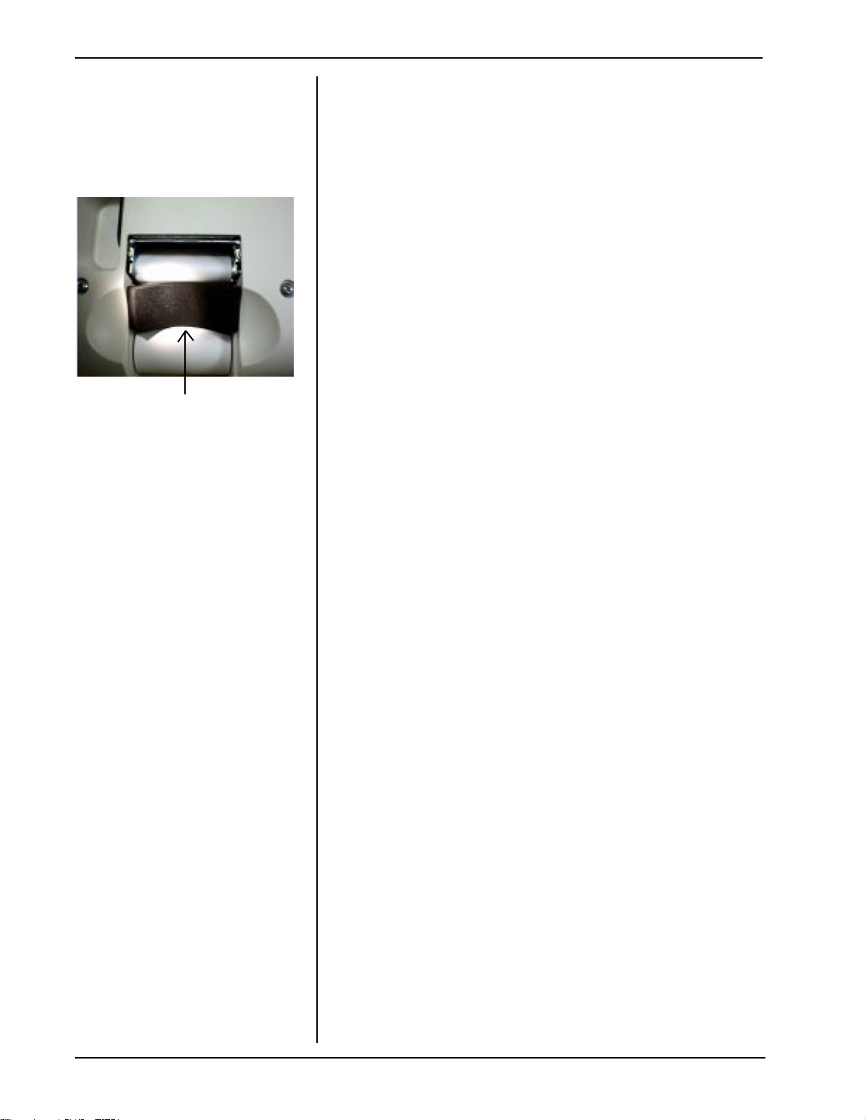
4.1.1 Lower paper door. See photo.
4.1.2 Remove paper:
a) pull lever down
b) pull paper out
Caution: It is essential that you
use proper ElectroStatic Discharge (ESD) precautions when
disassembling or handling the
instrument circuitry or printed
circuit boards (PCB’s). Many
components in the instrument
such as the MCU/PCB, are
highly susceptible to static
discharge damage. Keep all
boards in their protective ESD
packaging.
4.1.3 Remove 4 screws from rear
housing.
4.1.4 Lower rear housing/LCD assembly .
SERVICE MANUAL 112120 REV B
HUMPHREY FDT VISUAL FIELD INSTRUMENT 1
Page 38

Section 4 - Disassembly and Repair
4.1.5 Disconnect LCD ESD shield strap
from upper printer shelf. Use 11/32”
socket to remove nut.
4.1.6 Disconnect wiring from LCD/PCB:
a) Pull Printer Ribbon Cable
connector J1 from LCD/PCB .
4.1.6 Disconnect wiring from LCD/PCB:
b)Disconnect 3 connectors
(shown in photo from left to right)
Stepper Motor Connector - P3
Paper Out Connector - P2
Head Up Connector - P1
4.1.7 Place rear housing/LCD sub assem
bly into a clean anit-static bag for
later use.
4.1.8 Pull paper door up from base
housing.
2 HUMPHREY FDT VISUAL FIELD INSTRUMENT
SERVICE MANUAL 112120 REV B
Page 39

Section 4 - Disassembly and Repair
4.2 REPLACEMENT OF REAR
HOUSING/LCD ASSEMBLY
4.2.1 Reassemble in reverse order with follow
ing notes:
a) Push Keyed ribbon cable into
connector J1 of the LCD module.
b) Run wire assemblies OVER the
ribbon cable.
c) Restore P1, P1, and P3 connections
to the LCD/PCB.
d) Ensure that the LCD ESD ground
shield stays on the inside of the rear
housing as rear housing/LCD sub
assembly is closed. See photo.
4.2.2 Plug unit in and turn on
4.2.3 Replace paper roll per instructions in
user’s manual.
4.2.4 Close paper door.
4.3 DISASSEMBLY OF OPTICS
4.3.1 Remove rear housing/LCD sub
assembly. (Refer to 4.1)
4.3.2 Remove front housing:
a) Remove screw from front housing
b) Pull front housing out
SERVICE MANUAL 112120 REV B
HUMPHREY FDT VISUAL FIELD INSTRUMENT 3
Page 40

Section 4 - Disassembly and Repair
4.3.3 Remove left and right rear housings:
a) Pull clip from top of housings.
b) Remove screw from top inside of
unit to disconnect side housings
from front housings. (Use magnetic
tip screwdriver to keep the screw
from falling into the unit.)
4.3.3 Remove left and right rear housings:
c) Remove 2 screws that connect
each housing to chassis.
4.3.3 Remove left and right rear housings:
d)Pull housing up and out of base
assembly
4 HUMPHREY FDT VISUAL FIELD INSTRUMENT
SERVICE MANUAL 112120 REV B
Page 41

Section 4 - Disassembly and Repair
4.3.4 Remove visor/browrest assembly:
a) Unscrew 4 set screws (7/64” key)
b) Pull visor/browrest assembly off.
4.3.5 Remove screw and lockwasher from
right side of ground cable.
4.3.6 Remove slide/bracket/ rod assembly:
a)Remove screw and lock washer at
each end of the slide bracked/rod
assembly.
SERVICE MANUAL 112120 REV B
HUMPHREY FDT VISUAL FIELD INSTRUMENT 5
Page 42

Section 4 - Disassembly and Repair
4.3.6 Remove slide/bracket/ rod assembly:
b)Remove visor backplate from visor
guide by lifting out from top, then
up.
Caution: Do not break the visor guide
(indicated by arrow in photo
graph) in this step! Do not pull
the visor backplate out too far
as this will break the visor
guide!
4.3.6 Remove slide/bracket/ rod assembly:
c)Remove rod from slide-bracket.
Note: Place finger on visor wear pad to
prevent it from falling.
4.3.6 Remove slide/bracket/ rod assembly:
d)Remove visor wear-pad and visor
spring bracket.
6 HUMPHREY FDT VISUAL FIELD INSTRUMENT
SERVICE MANUAL 112120 REV B
Page 43

Section 4 - Disassembly and Repair
4.3.6 Remove slide/bracket/ rod assembly:
e)Remove 2 screws.
f)Remove bracket.
4.3.7 Remove front left and front right
housings:
a)Remove two black screws from
front of housings.
4.3.7 Remove front left and front right
housings:
b)Remove the rear EMI shield by
removing the nut on each side
(shown in Photo Inset) Use 11/32”
wrench or socket.
c)Remove 3 screws from each
housing.
SERVICE MANUAL 112120 REV B
HUMPHREY FDT VISUAL FIELD INSTRUMENT 7
Page 44

Section 4 - Disassembly and Repair
4.3.7 Remove front left and front right
housings:
d)Spread and lift housings from base.
4.3.8 Disconnect wiring:
a) Pull the VPS wires from J107 of
the MCU PCB.
4.3.8 Disconnect wiring:
b) Remove the screw and lock
washer which attaches the ground
wire ring terminal to the front ESD
shield.
8 HUMPHREY FDT VISUAL FIELD INSTRUMENT
SERVICE MANUAL 112120 REV B
Page 45

Section 4 - Disassembly and Repair
4.3.8 Disconnect wiring:
c)Lift front housing backplate from
optics tube assembly.
4.3.9 Remove front ESD shield:
a)Remove screws from both ends of
shield.
4.3.9 Remove front ESD shield:
b) Gently pull front ESD shield from
chassis without contacting compo
nents on the PCB.
SERVICE MANUAL 112120 REV B
HUMPHREY FDT VISUAL FIELD INSTRUMENT 9
Page 46

Section 4 - Disassembly and Repair
4.3.9 Remove front ESD shield:
c)Disconnect IP (Internal
Photodetector) connector from J110
of MCU/ PCB.
4.3.10 Remove optics tube assembly:
a)Remove 4 screws while supporting
optics tube assembly.
4.3.10 Remove optics tube assembly:
b)Remove optics tube assembly.
c)Put optics tube assembly into dust
free container or bag.
10 HUMPHREY FDT VISUAL FIELD INSTRUMENT
SERVICE MANUAL 112120 REV B
Page 47

Section 4 - Disassembly and Repair
4.4 ASSEMBLY OF OPTICS
4.4.1 Replace the optics tube assembly:
a)Place foam gasket into position.
Note: Notches on left and right sides of foam
gasket must fit over the tabs.
4.4.1 Replace the optics tube assembly:
b)Hold the optics tube assembly with
the IP PCB on the right side and fit it
onto the monitor.
4.4.1 Replace the optics tube assembly:
c)Position the optics tube assembly
all the way on to the Monitor/Chas
sis assembly. Make sure the optics
tube assembly is not caught on the
CRT band on top. Check slotted
holes. Photo at right depicts right
side of optics tube assembly
positioned all the way onto the
chassis.
d)Install and tighten 4 screws.
4.4.2 Place front housing backplate on to
front of optics tube assembly.(See
step 4.3.8)
SERVICE MANUAL 112120 REV B
HUMPHREY FDT VISUAL FIELD INSTRUMENT 11
Page 48

Section 4 - Disassembly and Repair
4.4.3 Replace front ESD shield and
restore connector to J110 of MCU
PCB :(See 4.3.10 a,b,c)
4.4.4 Restore wiring connections:
a)Ground Wire (See 4.3.9 b)
External Tooth lockwasher must
be used for ground connection.
b)VPS wire connector to J107 of
MCU PCB (See 4.3.9 a)
4.4.5 Replace front left and right housings:
a)Place wires while installing front
right housing.
Note:Proper alignment of front right and left
housings is critical to proper sliding of visor.
See photo for notch/tab relationship.
4.4.5 Replace front left and right housings:
b)Put housings onto threaded studs
at corners (this photo.)
c)Install slide/bracket rod assembly
(See 4.3.6)
d)Install 2 black screws into front
housings (See 4.3.8)
e)Fasten left and right housings with
3 screws each. Use the longer
where shown.
4.4.6 Install Rear EMI shield:
a)Shield must contact but not move
BLUE CAP of CRT. Put shield over
screws. Tighten nuts. See Tools.
4.4.7 Install Rod into slide bracket:
a)Put visor spring and visor wear pad
into position.
12 HUMPHREY FDT VISUAL FIELD INSTRUMENT
SERVICE MANUAL 112120 REV B
Page 49

Section 4 - Disassembly and Repair
4.4.7 Install Rod into slide bracket:
b)Hold wear pad in place and slide
the rod (as shown in photo) in
from the left side of bracket.
c)Test this assembly by sliding the
rod left and right. The rod must
engage the detent at each end of
the stroke to pass the test.
d)Put rod in center position.
4.4.8 Install visor backplate:
a)Put visor backplate into notch in
visor guide as shown in photo.
b)Put visor backplate over the slide
bracket/rod assembly. (See 4.3.6)
c)Attach visor backplate to rod with
screws and lockwashers. (See
4.3.6)
d)Restore ground cable connection
with screw and External tooth
lockwasher. (See 4.3.5)
4.4.9 Install visor/browrest sub assembly:
a)Slide the visor backplate to right.
b)Put visor/browrest onto visor
backplate with ground cable in
position shown in photo.
c)Secure with 4 set screws.
d)Test this assembly by sliding left
and right. The Visor must:
1)move smoothly
2)click (detent) at end of
stroke.
3)not rub the ground cable.
SERVICE MANUAL 112120 REV B
HUMPHREY FDT VISUAL FIELD INSTRUMENT 13
Page 50

Section 4 - Disassembly and Repair
4.4.10 Install left and right rear housings:
a)Put side housing bottom tabs into
slots in base.
b)Secure each cover with 2 screws
(See 4.3.3 c)
c)Fasten covers inside upper section
with one screw(See 4.3.3 b)
4.4.10 Install left and right rear housings:
d)Put clip on covers.
4.4.11 Install front housing:
a)Align tabs and secure with one
central screw. (See 4.3.2 a)
4.4.12 Install rear housing/LCD assembly:
a)Follow instructions in Section 4.2
NOTE: If a new Internal
Photodetector board was
installed, perform a Factory
Calibration.
14 HUMPHREY FDT VISUAL FIELD INSTRUMENT
SERVICE MANUAL 112120 REV B
Page 51

Section 4 - Disassembly and Repair
4.5 REMOVAL OF PRINTER
Note: Printers on early model FDT’s have
upper and lower printer shelves. Later
FDT units use printer enclosures which
are described in Section 9.5.
4.5.1 Remove rear housing/LCD
assembly (See 4.1)
4.5.2 Remove left and right rear housings
(See 4.3.3)
4.5.3 Remove upper printer shelf (see
photo):
a)Remove 2 screws with washers.
4.5.3 Remove upper printer shelf (see
photo):
b)Lift shelf out .
4.5.4 Remove ribbon cable from printer.
SERVICE MANUAL 112120 REV B
HUMPHREY FDT VISUAL FIELD INSTRUMENT 15
Page 52

Section 4 - Disassembly and Repair
4.5.5 Remove printer plate:
a)Remove 2 screws with washers.
b)Pull printer plate from chassis
4.6 INSTALLING PRINTER
4.6.1 Attach edge protectors as follows:
(see assembly drawing for exact
locations of edge protectors)
a)1 for each side of chassis
b)1 on the back of both printer
plates (shelfs).
c)1 circular protector on upper
printer plate (shown in photo).
4.6.2 Install printer/printer plate assembly
on chassis:
a)Secure with 2 screws.
b)Connect ribbon cable (keyed)
4.6.3 Replace upper printer shelf.See 4.5.3
a)Secure with 2 screws.
4.6.4 Install left and right rear housings.
(See 4.4.10)
4.6.5 Install front housing.(See 4.4.11)
4.6.6 Install rear housing/LCD assembly.
(See 4.4.12)
16 HUMPHREY FDT VISUAL FIELD INSTRUMENT
SERVICE MANUAL 112120 REV B
Page 53

Section 4 - Disassembly and Repair
4.7 REMOVAL OF MCU PCB
4.7.1 Remove rear housing/LCD assembly.
(See 4.1)
4.7.2 Remove Optics up to, but not in
cluding the optics tube assembly.
(See 4.3.1 through 4.3.10)
4.7.3 Disconnect wiring:
a)Unplug J7 and J102 of MCU PCB.
b)Unplug J1 (Shown in Photo)
4.7.3 Disconnect wiring:
c)Unplug PRB wire from J105 of
MCU PRB.
4.7.3 Disconnect wiring:
d)Unplug P5 from Monitor Board.
SERVICE MANUAL 112120 REV B
HUMPHREY FDT VISUAL FIELD INSTRUMENT 17
Page 54

Section 4 - Disassembly and Repair
4.7.4 Remove Chassis/Monitor/MCU assy:
a)Use 11/32” socket and extension
to remove 4 nuts at base of chas
sis.
4.7.4 Remove Chassis/Monitor/MCU assy:
b)Tilt chassis/Monitor/MCU assy.
forward as you lift up.
CAUTION: Do not allow the MCU board to
contact front edge of opening in
base (SEE arrow in photo.)
c)Lift assembly straight up from base.
CAUTION:See caution note and Photo #3 on
page 3 of Section 1 regarding not
standing the chassis monitor
asembly on the (RS232)
connec of the MCU/PCB.
4.7.5 Remove MCU/PCB from Chassis:
a)Remove 4 screws with split
lockwashers from MCU/PCB
four corners.
b)Gently remove MCU/PCB .
CAUTION: There are Board to Board pin
connectors (J108 and J109 )at
the top and bottom of the
MCU/ PCB. Separate the
boards carefully.
c)Remove PCB TO PCB connectors
from board and store board in
antistatic bag
18 HUMPHREY FDT VISUAL FIELD INSTRUMENT
SERVICE MANUAL 112120 REV B
Page 55

Section 4 - Disassembly and Repair
4.8 INSTALLING MCU/PCB
NOTE: Use PC utility to initialize/set
NVRAM when installing new
MCU/PCB. Factory calibration is also required.
4.8.1 Install MCU/PCB
a)Insert Connector,PCB to PCB (pn
112086) into top and bottom
sockets of new MCU/PCB.
b)Align the pins with the sockets of
Monitor Board in chassis and
gently press boards together.
c)Secure with 4 screws.
4.8.2 Install Chassis/Monitor/MCU assy.
a)Important:Move all wires from
footprint area of the chassis to
avoid pinching of wires.
4.8.2 Install Chassis/Monitor/MCU assy.
b)Tilt the chassis assembly forward.
SERVICE MANUAL 112120 REV B
HUMPHREY FDT VISUAL FIELD INSTRUMENT 19
Page 56

Section 4 - Disassembly and Repair
4.8.2 Install Chassis/Monitor/MCU assy.
c)Position chassis onto base plate
threaded studs.
d)Secure the chassis with 4 nuts.
4.8.3 Complete the installation of the MCU/
PCB by following steps 4.7.1 - 4.7.3
in reverse order.
NOTE: Use PC utility to initialize/set
NVRAM when installing new
MCU/PCB. Factory calibration is also required. See
Section 3 pg. 2 for additional
information on PC utility.
4.9 INSTALLING A REPLACEMENT
CHASSIS/MONITOR ASSEMBLY
4.9.1 Secure ribbon cable clamps to
chassis over ribbon cables.
4.9.2 Install MCU/PCB to new chassis.
4.9.3 Reassemble unit. Follow steps 4.7.1
through 4.7.3 in reverse order.
NOTE:
matched set. If either the CRT or the Monitor PCB
fails, a new matched chassis/monitor assembly
must be installed or the FDT will not function
properly. DO NOT ADJUST POTS!
The chassis/monitor assembly is a
4.9.4 Perform a Factory Calibration only if
you installed a new Chassis/Monitor.
4.10 REMOVAL OF TRANSFORMER
4.10.1 Remove rear housing/LCD assy.
(Sect. 4.1.1 - 4.1.8)
4.10.2 Remove front housing. (Sect. 4.3.2)
4.10.3 Remove left and right rear housings.
(Sect 4.3.3)
4.10.4 Disconnect J1 and J105 from MCU.
4.10.5 Partially lift Chassis/Monitor assembly
from base and disconnect P5 from
Monitor Board.
4.10.6 Remove Chassis/Monitor assembly.
(Sect. 4.7.4)
4.10.7 Remove Transformer from base.
a)Remove 4 nuts with 11/32” socket.
20 HUMPHREY FDT VISUAL FIELD INSTRUMENT
SERVICE MANUAL 112120 REV B
Page 57

Section 4 - Disassembly and Repair
4.10.7 Remove Transformer:
b)Disconnect transformer wires from
power entry module.
c)Lift transformer from base.
4.11 INSTALLING TRANSFORMER
4.11.1 Install transformer in reverse order of
removal.
4.11.2 Restore wiring connections.
a)Refer to Sheet 2 of Drawing
#112000 for correct placement of
transformer wires to power entry
module.
4.12 REMOVAL OF PRB JACK
4.12.1 Remove rear housing/LCD assy.
(Sect. 4.1.1 - 4.1.8)
4.12.2 Remove front housing. (Sect. 4.3.2)
4.12.3 Remove left and right rear housings.
(Sect 4.3.3)
4.12.4 Remove Upper printer shelf.
(Sect 4.5.3)
4.12.5 Disconnect J1 and J105 from MCU.
4.12.6 Disconnect P5 from Monitor Board.
4.12.7 Remove Chassis/Monitor assembly.
(Sect. 4.7.4)
4.12.8 Unscrew Ring Nut of PRB Jack with
T-15145 (See Photo)
4.13 REPLACEMENT OF PRB JACK
4.13.1 Install new PRB Wire Assembly (jack
and wire harness) in reverse order of
disassembly.
4.14 REMOVAL OF POWER ENTRY
MODULE
4.14.1 Remove Chassis/Monitor assembly
per above steps 4.12.1-4.12.7.
4.14.2 Separate Housing and Base Plate:
a)Remove 4 screws from rubber feet.
b)Lift housing from base.
SERVICE MANUAL 112120 REV B
HUMPHREY FDT VISUAL FIELD INSTRUMENT 21
Page 58

Section 4 - Disassembly and Repair
4.14.3 Remove wires from module.
4.14.4Slide power entry module up and out
of base plate.
4.15 REPLACEMENT OF POWER
ENTRY MODULE
4.15.1Install power entry module.
a)Press power entry module into
base plate assembly.
4.15.2 Restore wiring connections.
a)Refer to Sheet 2 of Drawing
#112000 for correct placement of
wires to power entry module.
4.15.2 Replace the housing in reverse order.
(See 4.14.1- 4.14.2)
4.16 REMOVAL OF VISOR POSITION
SENSOR (VPS) PRINTED CIRCUIT
BOARD (PCB)
4.16.1 Disassemble optics to VPS/PCB
(See 4.3)
4.16.2 Remove VPS/PCB
a)Cut cable tie.
b)Remove screw as shown in photo.
c)Disconnect VPS/PCB from front
housing backplate.
P1 Phillips
4.17 REPLACEMENT OF VPS/PCB
4.17.1 Install VPS/PCB in reverse order.
22 HUMPHREY FDT VISUAL FIELD INSTRUMENT
SERVICE MANUAL 112120 REV B
Page 59

Section 4 - Disassembly and Repair
4.18 REMOVAL OF INTERNAL PHOTO
DETECTOR (IP) PCB.
4.18.1 Disassemble optics to optics tube
assembly. (See 4.3)
4.18.2 Remove 2 screws from IP/PCB .
4.19 REPLACEMENT OF IP/PCB.
4.19.1 Install IP/PCB in reverse order of
removal. Make sure sensor is clean.
NOTE:If you replaced the IP with a new IP,
factory calibration is required.
4.20 REMOVAL OF LCD MODULE/
KEYPAD
4.20.1 Remove Rear housing/LCD
subassembly. Follow instructions in
Sect. 4.1.1 through 4.1.6.
4.20.2 Remove LCD module.
a)Unscrew 4 screws from module.
Note: Do not lose the insulating plastic
washer from screw shown in photo.
4.20.2 Remove LCD module.
b)Carefully lift module from housing.
SERVICE MANUAL 112120 REV B
HUMPHREY FDT VISUAL FIELD INSTRUMENT 23
Page 60

Section 4 - Disassembly and Repair
4.20.3 Remove keypad
a)Lift keypad from housing.
4.21 REPLACEMENT OF LCD MODULE/
KEYPAD
4.21.1 Perform LCD module/keypad removal
in reverse order.
NOTE: Install plastic insulating washer
in position as shown in photo.
This screw prevents shorting of
adjacent component and is
found in both CE and non CE
units.
4.22 REMOVAL OF VISOR PAD
4.22.1 Remove visor/browrest sub assembly
(Sect. 4.3.4)
4.22.2 Remove visor pad
a)Pull and press simultaneously in
directions of arrows as shown in
photo.
b)Repeat with other end of visor pad.
24 HUMPHREY FDT VISUAL FIELD INSTRUMENT
SERVICE MANUAL 112120 REV B
Page 61

Section 4 - Disassembly and Repair
4.23 INSTALLING VISOR PAD
4.32.1 Install visor pad.
a)Place visor into visor as shown.
b)Press loops over posts on inside of
visor.
4.23.2 Replace visor/browrest sub assembly
(Sect. 4.4.9)
4.24 REMOVAL OF ACRYLIC LENSES
and OPTICS TUBE WINDOW
4.24.1 Remove optics tube assembly
(Sect. 4.3)
4.24.2 Remove optics tube housing:
a)Remove screws that hold housings
together.
b)Carefully pull one housing off.
4.24.3 Remove acrylic lenses and or optics
tube window by holding edges and
gently sliding them from the optics
tube.
4.24.4 If lenses or optics tube window are
dirty, clean with a swab and alcohol
and air dry.
If a lens cannot be cleaned, install a
clean replacement lens.
SERVICE MANUAL 112120 REV B
HUMPHREY FDT VISUAL FIELD INSTRUMENT 25
Page 62

Section 4 - Disassembly and Repair
4.25 INSTALLING ACRYLIC LENSES
and OPTICS TUBE WINDOW.
NOTE:Since replacement lenses and window
may have slightly different light transmittance characteristics , it is important to
perform Factory Calibration.
4.25.1 Assure that all lenses have foam tape
on edges. See Drawing#112000.
4.25.2 Clean housings with air.
NOTE:SEE PHOTO AT RIGHT. Be careful to
leave one space between the lenses when
inserting them into the housings. If put into
two adjacent grooves, they will scratch
eachother when inserting the second one.
4.25.3 Put lenses and optics tube window
into one optics tube.
4.25.4 Assemble housings together.
a)Slide other optics tube over lenses.
b)Replace screws.
4.25.5 Reassemble optics (Sect. 4.4)
4.25.6 If any combination of new lenses
and/or optics tube window have been
installed, perform factory calibration.
26 HUMPHREY FDT VISUAL FIELD INSTRUMENT
SERVICE MANUAL 112120 REV B
Page 63

Section 5 - Interconnect Diagrams
Interconnect Diagram
112119 Rev B
(2 sheets)
SERVICE MANUAL 112120 REV. B
HUMPHREY FDT VISUAL FIELD INSTRUMENT 1
Page 64

Page 65

6 Repair Parts
This column shows the quantities
to order to get started per 100
FDT Instruments in your market.
A shaded box indicates low
probability that the part will be
needed. THIS IS ONLY AN
ESTIMATE TO GET STARTED.
These columns indicate voltage
of country of use. The check
mark indicates the part is found
in the unit of that voltage.
This column displays a number
which appears on the assembly
drawing. The number points out
the specific part. “NA” indicates
that the part is not referenced on
the assembly drawing.
Key to Repair Parts List
Description of part.
Note: All fastener parts are
listed at the end of the
spreadsheet.
Manufacturer repair part number.
Part No. Description Bubble Number 115 V 230 V Recommended
SERVICE MANUAL 112120 REV. B
HUMPHREY FDT VISUAL FIELD INSTRUMENT 1
Page 66

6 Repair Parts
x
x
Part No. Description Bubble Number 115V 230V
M11526 ANTISTATIC POLY BAG(30X36)PINK N/A
112050-502 PRB ASSEMBLY (BLACK) N/A
112065-2 LABEL, PRB MODEL N/A
112098 FDT - USER'S GUIDE, ENGLISH N/A
112098C OPERATING INSTRUCTIONS, N/A
112098FR FDT USER'S GUIDE, FRENCH N/A
112098GR FDT USER'S GUIDE, GERMAN N/A
112098IT FDT USER'S GUIDE, ITALIAN N/A
112098SP FDT USER'S GUIDE, SPANISH N/A
112113-504 BOX ASSEMBLY N/A
112131 DESICCANT BAG N/A
112132 FDT, REGISTRATION CARD,ENGLISH N/A
112136 FDT - QUICK REFERENCE,ENGLISH N/A
761076-0 POWER CORD, DETACH.(DOM/JAPAN) N/A
761076-2 POWER CORD, DETACH. (EUROPEAN) N/A
761076-4 POWER CORD, DETACH. (UK) N/A
761076-6 POWER CORD, DETACH. (AUSTRALIA) N/A
112120 REPAIR MANUAL N/A
112002-1 BASE PLATE ASSY 0001
112002-2 BASE PLATE ASSY 0001
112101-1 PRB, WIRE ASSY 0002
112143-2 PRB, WIRE ASSY 0002
112075 WIRECLIP 0003
112006-1 TRANSFORMER (120V/230V ISOLAT) 0004
112006-2 TRANSFORMER 0004
112005 POWER ENTRY MODULE 0006
112085-1 WIRE ASSY, 4.25 0007
488383 GROUND LABEL 0008
112064-2 LABEL, FUSE/READ MANUAL 0009
112003-2 HOUSING,BASE 0010
112004-2 FOOT, RUBBER (BLACK) 0011
112057-4 LABEL,MODEL DOMESTIC 0013
112057-3 LABEL,MODEL INTL 0013
M11478 PARTS LABEL 0014
112067-1 LABEL, CONNECTOR ID 0015
112007-1 VISOR 0016
236174-1 BATTERY COVER PAD 0017
112010-1 BROWREST 0018
112008-1 OPTICS TUBE 0019
112076-501 PCB ASSY, LIGHT METER 0020
112141-502 PCB ASSY, LIGHT METER 0020
112013 LENS, ACRYLIC 0022
112110-2 FOAM TAPE, LENS 0023
112011-1 WINDOW, OPTICS TUBE 0024
112110-1 FOAM TAPE OPTICS TUBE WINDOW 0025
112056 MONITOR GASKET 0027
112025-505 HOUSING,REAR, PRINTED 0029
112025-505R HOUSING,REAR, PRINTED 0029
112043-1 LCD ESD SHIELD 0030
112145 LCD ESD SHIELD 0030
112042-1 WINDOW,LCD 0031
112092-1 LCD BUTTONS 0032 1
2 HUMPHREY FDT VISUAL FIELD INSTRUMENT
xx
xx
xx
xx
x
x
x
x
x
xx
xx
xx
xx
x
x
x
x
xx
x
x
x
x
xx
x
x
xx
xx
xx
xx
xx
xx
x
x
xx
xx
xx
xx
xx
xx
x
x
xx
xx
xx
xx
xx
x
x
x
x
xx
SERVICE MANUAL 112120 REV. B
10
2
2
2
2
2
2
1
20
2
2
2
2
1
1
1
2
2
2
1
1
4
2
2
1
2
1
1
10
2
2
2
4
2
4
10
1
1
1
1
5
Page 67

6 Repair Parts
Part No. Description Bubble Number115V230VRecommended
112091-1T LCD MODULE 0033
112091-2 LCD MODULE 0033
106103-43 MYLAR WASHER 0034
112041-502 MONITOR ASSY 0035
112041-503 MONITOR ASSY 0035
112037-504 PCB ASSY,MCU 0036
112086 CONNECTOR, PCB TO PCB 0037
112105-2 FRONT ESD SHIELD 0040
112026 PRINTER SHELF W/ PEMS 0042
112124-1 EDGE PROTECTOR 0043
112017 THERMAL PRINTER, 2 0044
112044-1 RIBBON CABLE ASSY, PRN (26PSN) 0046
112074 LABEL, OPTICS TUBE 0047
112072-2 FRONT HSG BACKPLATE W/ PEMS 0048
112085-2 WIRE ASSY,10.5 0049
112033-1 GUIDE, VISOR 0052
112079-501 PCB ASSY, VPS 0053
112142-501 PCB ASSY, VPS 0053
112049-3 HOUSING, FRONT LEFT 0055
112048-3 HOUSING, FRONT RIGHT 0057
106144-5 NYLINER BEARING 0059
112031-1 SLIDE BRACKET 0060
112018 SPRING VISOR 0062
112081 VISOR WEAR PAD 0063
112082-2 ROD, FINISHED 0064
112061-1 LABEL, VPS REFLECTIVE 0065
112039-1 VISOR BACKPLATE ASSY 0066
112094 FLEX CABLE W/ RINGS 0068
112124-3 EDGE PROTECTOR 0070
112077 RIBBON CABLE CLAMP 0071
112077-2 CABLE CLAMP 0071
112080-4 EDGE PROTECTOR,U CHANNEL 3.14 0072
112063 UPPER SHELF W/ PEMS 0073
112046-2 HOUSING, REAR RIGHT 0074
112044-2 LCD CABLE ASSY (40PSN) 0075
112124-2 EDGE PROTECTOR, 4 0076
112047-2 HOUSING, REAR LEFT 0077
112068-2 LABEL, PAPER LOADING INSTR 0079
112027-4 HSG, PAPER DOOR,PRINTED 0080
112019 THERMAL PAPER ROLL, 2 0081
112024-4 HSG,FRONT COVER,PRINTED 0083
112129-1 LABEL, FRONT COVER LOGO G 0085
106138-6 SCREW, BUTTON HS SOCKET G 0086
112066 LABEL, BACKGRND DEBUG CONN 0088
112078-1 CALIBRATION CAP 0090
106127-1 STANDOFF-SCREW MOUNT 0095
112121 CLIP 0096
112122 EMI SHIELD, REAR 0098
112155 EMI SHELD, CRT 0098
112130 FOAM, PAPER ROLL 0099
236706-3109 FUSE, 160 MA 0100
236706-3112 FUSE- 315 MA 0100
x
x
xx
x
x
xx
xx
xx
x
xx
xx
xx
xx
xx
xx
xx
x
x
xx
xx
xx
xx
xx
xx
xx
xx
xx
xx
x
x
x
xx
x
xx
x
x
xx
xx
xx
xx
xx
xx
xx
xx
x
xx
xx
xx
x
xx
x
x
1
1
6
1
1
1
4
2
1
2
1
2
5
1
1
1
1
2
1
5
5
1
1
1
1
1
1
2
1
1
2
1
1
60
1
1
10
10
20
4
20
1
1
60
20
20
SERVICE MANUAL 112120 REV. B
HUMPHREY FDT VISUAL FIELD INSTRUMENT 3
Page 68

6 Repair Parts
x
Part No. Description Bubble Number 115V 230V Recommended
112140-1 JUMPER ASSY RS232 0103
112133-1 FRONT EMI SHIELD 0104
112135 PRINTER ENCLOSURE 0108
112147 PRINTER GASKET 0109
112151 COPPER TAPE 0110
112149 FOAM, BLOCK 0111
112137 BASE SHIELD 0112
112146 TOP EMI SHIELD 0113
112150 FOAM, STRIP 0114
112148 PRINTER ENCLOSURE GASKET 0115
112138-501 SHIELDED RIBBON CABLE ASSY 0116
761077-1 TIE WRAP 0117
106137-2 NUT,8-32 EXTLOCK 0005
106100-51 PHPS 8-32 X .750 0012
106124-4 #4 X.250 LG PPHS SELF TPG 0021
106124-30 SCREW #6 X .375 0026
106105-3 #4 LOCKWASHER,HEL 0038
106100-42 4-40 X.25 SCREW 0039
106100-12 PHPS 8-32 X.281 0041
711776 SCREW,M3 PHPS METRIC 0045
745147 #6 LOCKWASHER-EXTERNAL TOOTH 0050
106100-50 6-32 X .125 PHILLIPS,STL 0051
106124-31 #4 X.250 LG PPHS SELF TPG 0054
106102-27 FHPHPS 6X32X.250 LG 0056
483017 PHPS 6-32 X 5/16 0061
106140-5 6-32 W/EXT WASHER 0067
106140-9 8-32 W/EXT WASHER 0069
106124-36 SCREW .500 AB PAN PHILLIPS 0078
106119-34 .344 HEX SOCKET ST BLACK ANODI 0089
106137-7 NUT 6-32 EXTLOCK 0094
106100-52 PHPS 8-32 X .500 0097
106103-6 WASHER, FLAT 0106
x
x
x
x
x
x
x
x
x
x
x
x
xx
xx
xx
xx
xx
xx
xx
xx
xx
xx
xx
xx
xx
xx
xx
xx
xx
xx
xx
1
1
1
1
2
1
1
12
12
12
12
12
12
12
12
12
12
12
12
12
12
12
12
12
12
12
4 HUMPHREY FDT VISUAL FIELD INSTRUMENT
SERVICE MANUAL 112120 REV. B
Page 69

Section 7 - FDT Assembly Drawings
FDT Assemby Drawings:
112000 Domestic
sh1 Rev D
sh2 Rev D
sh3 Rev D
112200 International
sh1 Rev B
sh2 Rev A
sh3 Rev B
sh4 Rev B
SERVICE MANUAL 112120 REV. B
HUMPHREY FDT VISUAL FIELD INSTRUMENT 1
Page 70

Page 71

Section 8 - Schematics
Schematics
112106
Schematic, Controller PCB, Patt C
sh1 Rev D
sh2 Rev D
112091
Schematic, LCD Module Custom
Circuitry
sh3 Rev C
112037
PCB Assembly, MCU
Rev D
SERVICE MANUAL 112120 REV. B
HUMPHREY FDT VISUAL FIELD INSTRUMENT 1
Page 72

Page 73

Section 9 - Disassembly and Repair CE Model
EXERCISE EXTREME
CAUTION WHEN SERVICING THE FDT!
THE MONITOR ASSEMBLY OPERATES
ON APPROXIMATELY 10,000 VOLTS!
NOTE: Properly re-install all ESD shields
and ground wires to maintain EMI
protection standards!
9.1 REMOVAL OF REAR HOUSING/LCD
9.1.1 Lower paper door.
9.1.2 Remove paper:
a) pull lever down
b) pull paper out
Caution: It is essential that you
use proper ElectroStatic Discharge (ESD) precautions when
disassembling or handling the
instrument circuitry or printed
circuit boards (PCB’s). Many
components in the instrument
such as the MCU/PCB, are
highly susceptible to static
discharge damage. Put PCB’s in
ESD bags when they are removed from the FDT.
9.1.3 Remove 4 screws from rear
housing.
9.1.4 Lower rear housing/LCD assembly .
Copper ESD shields may have
sharp edges. Exercise caution to
avoid cuts!
SERVICE MANUAL 112120 REV B
HUMPHREY FDT VISUAL FIELD INSTRUMENT 1
Page 74

Section 9 - Disassembly and Repair CE Model
9.1.5 Disconnect LCD ESD shield from top
of printer enclosure. Remove nut with
11/32” socket.
11/32”socket
9.1.6 Disconnect wiring from LCD board:
a) Pull Printer Ribbon Cable connect tor J1 from LCD printed circuit
board.
9.1.6 Disconnect wiring from LCD board:
b)Disconnect 3 connectors (shown
from left to right) Stepper Motor
Connector P3, Paper Out Connec
tor P2, and Head Up Connector
P1.
9.1.7 Cut cable tie shown by arrow in photo.
and place rear housing/LCD sub
assembly into a clean anit-static bag
for temporary storage.
9.1.8 Remove paper door.
2 HUMPHREY FDT VISUAL FIELD INSTRUMENT
SERVICE MANUAL 112120 REV B
Page 75

Section 9 - Disassembly and Repair CE Model
9.2 REPLACEMENT OF REAR
HOUSING/LCD ASSEMBLY
9.2.1 Reassemble in reverse order with follow
ing notes:
a) Push Keyed ribbon cable into
connector J1 of the LCD module.
b) Secure P1, P2, P3 wires to the LCD
shield ground strap with a wire tie.
c) Restore P1, P2, and P3 connections
to the LCD module.
d) Ensure that the LCD ESD ground
shield stays on the inside of the rear
housing as rear housing/LCD sub
assembly is closed. See photo.
9.2.2 Plug unit in and turn on
9.2.3 Replace paper roll per instructions in
user’s manual.
9.2.4 Close paper door.
NOTE: Factory calibration is not required
when replacing the LCD module assembly.
9.3 DISASSEMBLY OF OPTICS
9.3.1 Remove rear housing/LCD sub
assembly. (Refer to 9.1)
9.3.2 Remove front housing:
a) Remove screw from front housing
Use a 3/32” hex key.
b) Pull front housing out
SERVICE MANUAL 112120 REV B
HUMPHREY FDT VISUAL FIELD INSTRUMENT 3
Page 76

Section 9 - Disassembly and Repair CE Model
9.3.3 Remove left and right rear housings:
a) Pull clip from top of housings.
Note: Use a screwdriver with a magnetized tip
to prevent screw from falling into unit in step
(b) below.
b) Remove screw from inside of
housings.
9.3.3 Remove left and right rear housings:
c) Remove 2 screws that connect
each housing to chassis.
9.3.3 Remove left and right rear housings:
d)Pull housing up and out of base
assembly
4 HUMPHREY FDT VISUAL FIELD INSTRUMENT
SERVICE MANUAL 112120 REV B
Page 77

Section 9 - Disassembly and Repair CE Model
9.3.4 Remove visor/browrest assembly:
a) Unscrew 4 set screws (7/64” key)
b) Pull visor/browrest assembly off.
9.3.5 Remove screw and lockwasher from
right side of ground cable.
9.3.6 Remove slide/bracket/ rod assembly:
a)Remove screws and lock washers
from both ends of the slide rod.
SERVICE MANUAL 112120 REV B
HUMPHREY FDT VISUAL FIELD INSTRUMENT 5
Page 78

Section 9 - Disassembly and Repair CE Model
9.3.6 Remove slide/bracket/ rod assembly:
b)Remove visor backplate from visor
guide by lifting out from top, then
up.
Caution: Improper removal of the
visor backplate may damage
the visor guide (see arrow in
photo). Carefully lift the visor
backplate away from the
unit. Do not pull it away.
9.3.6 Remove slide/bracket/ rod assembly:
c)Remove rod from slide-bracket.
Note: Place finger on visor wear pad to
prevent it from falling.
9.3.6 Remove slide/bracket/ rod assembly:
d)Remove visor wear-pad and visor
spring bracket.
6 HUMPHREY FDT VISUAL FIELD INSTRUMENT
SERVICE MANUAL 112120 REV B
Page 79

Section 9 - Disassembly and Repair CE Model
9.3.6 Remove slide/bracket/ rod assembly:
e)Remove 2 screws.
f)Remove bracket.
9.3.7 Remove front left and front right
housings:
a)Remove two black screws from
front of housings.
9.3.7 Remove front left and front right
housings:
b)Remove the nut and center screw
from each housing.
Nut also holds EMI shield (Inset).
Use 11/32” wrench or socket.
c)Remove 2 remaining screws from
front left and front right housings.
SERVICE MANUAL 112120 REV B
HUMPHREY FDT VISUAL FIELD INSTRUMENT 7
Page 80

Section 9 - Disassembly and Repair CE Model
9.3.7 Remove front left and front right
housings:
d)Spread and lift housings from base.
9.3.8 Lift front housing backplate from
optics tube assembly.
9.3.9 Remove shields:
a)Remove top shield.(photo).
b)Push bottom shield down and away
from optics tube assembly.
8 HUMPHREY FDT VISUAL FIELD INSTRUMENT
SERVICE MANUAL 112120 REV B
Page 81

Section 9 - Disassembly and Repair CE Model
9.3.10 Remove Internal Photodetector (IP).
9.3.11 Remove optics tube assembly:
a)Remove 4 screws while supporting
optics tube assembly.
9.3.11 Remove optics tube assembly:
b)Remove optics tube assembly.
c)Put optics tube assembly into a
dust-free bag for storage.
d)If necessary, remove foam gasket
carefully.
SERVICE MANUAL 112120 REV B
HUMPHREY FDT VISUAL FIELD INSTRUMENT 9
Page 82

Section 9 - Disassembly and Repair CE Model
9.4 ASSEMBLY OF OPTICS
9.4.1 Replace the optics tube assembly:
a)Place foam gasket into position.
Note: Notches on left and right sides of foam
gasket must fit over the tabs.
9.4.1 Replace the optics tube assembly:
b)Hold the optics tube assembly with
the Internal Photodetector (IP)
window on the right side.
c)Position the optics tube assembly
onto the Monitor/Chassis assembly
until the slotted holes are in the
position shown in the photo at right.
9.4.2 Secure Optics Tube and Internal
Photodetector (IP).
a) Check to make sure optics tube
assembly is on top of the CRT
metal band and secure it with 4
screws.
b) Make sure IP chip surface is clean
and attach IP/PCB to optics tube
assembly with 2 screws.
NOTE: Use very slight torque to tighten 2
IP/PCB screws.
10 HUMPHREY FDT VISUAL FIELD INSTRUMENT
SERVICE MANUAL 112120 REV B
Page 83

Section 9 - Disassembly and Repair CE Model
9.4.3 Restore top and bottom ESD shields
on the optical tube assembly.
9.4.4 Position the front housing backplate
onto the optics tube assembly.
9.4.5 Replace front left and right housings:
a)Position housings onto chassis.
Note: make sure shielded cables do not get
caught between housings under optics tube
assembly. Smooth operation of the visor
depends on proper alignment of housings
with the optics tube assembly. Assemble
and align the notches in the housings with
the optics tube assembly as shown in the
photo at right.
9.4.5 Replace front left and right housings:
b)Install slide/bracket rod assembly .
See 9.3.6)
c)Install 2 black screws into front
housings.(See 9.3.7)
d)Fasten left and right housings with
3 screws each. Use the long screw
where shown in photo at right.
9.4.6 Install Rear EMI shield:
a)Shield must contact but not move
BLUE CAP of CRT. Put shield over
screws. Use 11/32” wrench or
socket.
9.4.7 Install Rod into slide bracket:
a)Put visor spring and visor wear pad
into position.
Note: small metal tabs at end of spring
face toward unit.
SERVICE MANUAL 112120 REV B
HUMPHREY FDT VISUAL FIELD INSTRUMENT 11
Page 84

Section 9 - Disassembly and Repair CE Model
9.4.7 Install Rod into slide bracket:
b)Hold wear pad in place and slide
the rod (as shown in photo) in
from the left side of bracket.
c)Test this assembly by sliding the rod
left and right. The rod must
engage the detent at each end of
the stroke.
d)Put rod in center position.
9.4.8 Install visor backplate:
a)Put visor backplate into notch in
visor guide as shown in photo.
b)Put visor backplate over the slide
bracket/rod assembly. (See 9.3.6 b)
c)Attach visor backplate to rod with
screws and lockwashers. (See
9.3.6 a)
d)Restore ground cable connection
with screw and External tooth
lockwasher. (See 9.3.5)
9.4.9 Install visor/browrest sub assembly:
a)Slide the visor backplate to right.
b)Put visor/browrest onto visor
backplate with ground cable in
position shown in photo.
c)Secure with 4 set screws.
d)Test this assembly by sliding left
and right. The Visor must:
1)move smoothly
2)click (detent) at end of
stroke.
3)not rub the ground cable.
12 HUMPHREY FDT VISUAL FIELD INSTRUMENT
SERVICE MANUAL 112120 REV B
Page 85

Section 9 - Disassembly and Repair CE Model
9.4.10 Install left and right rear housings:
a)Put side housing bottom tabs into
slots in base.
Note: See photo inset for foam block
reference. Make sure foam block is in place
before installing rear right housing .
b)Secure each cover with 2 screws
(See 9.3.3 c)
c)Fasten covers inside upper section
with one screw(See 9.3.3 b)
9.4.10 Install left and right rear housings:
d)Put clip on covers.
Right Rear Housing
Base
9.4.11 Install front housing:
a)Align tabs of front housing with slots
in base and secure with one
central screw. (See 9.3.2 a)
9.4.12 Install rear housing/LCD assembly:
a)Follow instructions in Section 9.2
NOTE: If a new Internal Photodetector (IP)
was installed, factory calibration is required.
SERVICE MANUAL 112120 REV B
HUMPHREY FDT VISUAL FIELD INSTRUMENT 13
Page 86

Section 9 - Disassembly and Repair CE Model
9.5 REMOVAL OF PRINTER
9.5.1 Remove rear housing/LCD
assembly (See9.1)
9.5.2 Remove left and right rear housings
(See9.3.3)
9.5.3 Remove ribbon cable to printer
module . (See photo.)
9.5.4 Remove 4 screws (with external tooth
washers) which hold printerassembly
to chassis.
9.5.5 Remove printer assembly from
chassis.
14 HUMPHREY FDT VISUAL FIELD INSTRUMENT
edge protector
SERVICE MANUAL 112120 REV B
Page 87

Section 9 - Disassembly and Repair CE Model
9.5.6 Remove printer:
a)Remove 2 screws.
9.5.6 Remove printer:
b) Remove printer from housing.
9.6 INSTALLING PRINTER
9.6.1 Reassemble in reverse order of
disassembly with special attention to
the following Notes.
Note: Make sure copper clips are installed in
position shown in upper photo at right. They
should snap into small holes in chassis.
Note:Make sure base shield tabs are in
position relative to bottom of printer assembly as shown in lower photo at right.
Note: Make sure circular edge protector is
installed on printer assembly. (See 9.5.5)
SERVICE MANUAL 112120 REV B
BASE SHIELD
View looking up under printer assembly.
HUMPHREY FDT VISUAL FIELD INSTRUMENT 15
Page 88

Section 9 - Disassembly and Repair CE Model
9.7 REMOVAL OF MCU PCB
9.7.1 Remove rear housing/LCD assembly.
(See 9.1)
9.7.2 Follow Remove Optics steps 9.3.1 to
9.3.8 (Lift front housing backplate from
optics tube assembly.) Do not remove
optics tube assembly.
9.7.3 Remove Printer (See 9.5)
9.7.4 Remove base shield.
See photo at right.
9.7.5 Disconnect wiring:
a)Open flap on front EMI shield foil as
shown in Step 9.7.5.
b)Remove Visor Position Sensor
PCB (VPS)ground wire ring terminal
c)Remove Patient Response Button
(PRB) ground wire ring terminal.
d)Unplug J 107
e)Unplug J105
f)Ground wire ring terminal for front
housing back plate. See inset.
9.7.5 Disconnect wiring:
d)Unplug P5 from Monitor Board.
e)Disconnect transformer purple wire
pair from connector located near
transformer.
EMI Shield over MCU/PCB
16 HUMPHREY FDT VISUAL FIELD INSTRUMENT
SERVICE MANUAL 112120 REV B
Page 89

Section 9 - Disassembly and Repair CE Model
9.7.4 Remove Chassis/Monitor/MCU assy:
a)Use 11/32” socket and extension
to remove 4 nuts holding chassis to
the base.
9.7.4 Remove Chassis/Monitor/MCU assy:
b)Tilt chassis/Monitor/MCU assy.
forward.
11/32”
CAUTION:Screw shown in photo will cause
difficulty in removing chassis assembly from
base. Do not apply force that might press
MCU board (under foil) against base.
c)Lift assembly straight up from base
and lay on table with copper foil
shield facing up.
9.7.5 Remove MCU/PCB from Chassis:
a)Remove 4 screws holding shield
over MCU/PCB.
SERVICE MANUAL 112120 REV B
top right screw
HUMPHREY FDT VISUAL FIELD INSTRUMENT 17
Page 90

Section 9 - Disassembly and Repair CE Model
9.7.5 Remove MCU/PCB from Chassis:
b)Lift EMI shield up.
9.7.5 Remove MCU/PCB from Chassis:
c)Remove Internal jPhotodetector (IP)
ground wire ring terminal from front
ESD shield as shown in photo.
d)Remove front ESD shield.
EMI SHIELD
IP ground
wire ring
terminal
9.7.5 Remove MCU/PCB from Chassis:
e)Disconnect J7 (shown in photo)
and J102 ribbon cable connectors,
IP connector J110 and J1.
f)Remove 4 screws with split
lockwashers from MCU/PCB.
g)Gently remove MCU/PCB and store
in ESD bag .
CAUTION: There are Board to Board pin
connectors (J108 and J109 )at
the top and bottom of the
MCU/ PCB. Separate the
boards carefully.
front ESD shield
18 HUMPHREY FDT VISUAL FIELD INSTRUMENT
SERVICE MANUAL 112120 REV B
Page 91

Section 9 - Disassembly and Repair CE Model
9.8 INSTALLING MCU/PCB
NOTE: Use PC utility to initialize/set
NVRAM when installing new
MCU/PCB. Factory calibration is also required. See
Section 3 pg. 2 for additional
information on PC utility.
9.8.1 Install MCU/PCB
a) Insert Connector,PCB to PCB (pn
112086) into top and bottom
sockets of new MCU/PCB.
b) Align the pins with the sockets of
Monitor Board in chassis and
gently press boards together.
9.8.1 Install MCU/PCB
c) Secure with 4 screws.
d) Restore connections.
e) Install front ESD shield.
9.8.1 Install MCU/PCB
g) Attach copper EMI shield to chassis
with 4 screws.
Note: Make sure to attach ground wire on
bottom right side of EMI shield with lower
right screw as shown in photo.
SERVICE MANUAL 112120 REV B
lower right screw
HUMPHREY FDT VISUAL FIELD INSTRUMENT 19
Page 92

Section 9 - Disassembly and Repair CE Model
9.8.2 Install Chassis/Monitor/MCU assy:
a)Important:Make sure wires trans
former wires and PRB wires do not
get caught under chassis.
b)Tilt the chassis assembly forward.
and lower chassis onto studs.
d)Secure the chassis with 4 nuts.
9.8.3 Complete the installation of the MCU/
PCB by following steps 9.7.1 - 9.7.3
in reverse order.
NOTE: Use PC utility to initialize/set
NVRAM when installing new MCU/
PCB. Factory calibration is also
required. See Section 3 pg. 2 for
additional information on PC utility.
9.9 INSTALLING A REPLACEMENT
CHASSIS/MONITOR ASSEMBLY
9.9.1 Secure ribbon cable clamps to
chassis over ribbon cables.
9.9.2 Install MCU/PCB to new chassis.
9.9.3 Reassemble unit. Follow steps 9.7.1
through 9.7.3 in reverse order.
NOTE:The chassis/monitor assembly is a
matched set. If either the CRT or the Monitor PCB
fails, a new matched chassis/monitor assembly
must be installed or the FDT will not function
properly. DO NOT ADJUST POTS!
9.9.4 Perform a Factory Calibration only if
you installed a new Chassis/Monitor.
9.10 REMOVAL OF TRANSFORMER
9.10.1 Remove rear housing/LCD assy.
(Sect. 9.1.1 - 9.1.8)
9.10.2 Remove front housing. (Sect. 9.3.2)
9.10.3 Remove left and right rear housings.
and shield by CRT . (Sect 9.3.3)
9.10.4 Remove printer enclosure and shield.
See Sect9.5 and photo at right.
9.10.5 Disconnect J1 and J105 from MCU.
9.10.6 Disconnect P5 from Monitor Board.
9.10.7 Remove Transformer from base.
a)Remove 4 nuts with 11/32” socket.
20 HUMPHREY FDT VISUAL FIELD INSTRUMENT
BASE
Shield
SERVICE MANUAL 112120 REV B
Page 93

Section 9 - Disassembly and Repair CE Model
9.10.7 Remove Transformer:
b)Disconnect transformer wires from
power entry module.
c)Lift transformer from base.
9.11 INSTALLING TRANSFORMER
9.11.1 Install transformer in reverse order of
removal.
9.11.2 Restore wiring connections.
a)Refer to Sheet 2 of Drawing
#112200 for correct placement of
transformer wires to power entry
module.
NOTE: Make sure the notch in the copper
shield (Bubble No. 112 on drawing
112200 sheet 1 of 4) is on lower left side.
9.12 REMOVAL OF PRB JACK
9.12.1 Remove rear housing/LCD assy.
(Sect. 9.1.1 - 9.1.8)
9.12.2 Remove front housing. (Sect. 9.3.2)
9.12.3 Remove left and right rear housings.
(Sect 9.3.3)
9.12.4 Remove printer enclosure shelf.
(Sect 9.5.3)
9.12.5 Disconnect purple wire connector at
transformer and J105 and ground
from MCU.
9.12.6 Disconnect P5 from Monitor Board.
9.12.7 Remove Chassis/Monitor assembly.
(Sect. 9.7.4)
9.12.8 Unscrew Ring Nut of PRB Jack with
T-15145 (See Photo)
9.13 REPLACEMENT OF PRB JACK
9.13.1 Install new PRB Wire Assembly (jack
and wire harness) in reverse order of
disassembly.
9.14 REMOVAL OF POWER ENTRY
MODULE
9.19.1 Remove Chassis/Monitor assembly
per above steps 9.12.1-9.12.7.
9.19.2 Separate Housing and Base Plate:
a)Remove 4 screws from rubber feet.
b)Lift housing from base.
SERVICE MANUAL 112120 REV B
HUMPHREY FDT VISUAL FIELD INSTRUMENT 21
Page 94

Section 9 - Disassembly and Repair CE Model
9.19.3 Remove wires from module.
9.19.4 Slide power entry module up and out
of base plate.
9.15 REPLACEMENT OF POWER
ENTRY MODULE
9.15.1Install power entry module.
a)Press power entry module into
base plate assembly.
9.15.2 Restore wiring connections.
a)Refer to Sheet 2 of Drawing
#112000 for correct placement of
wires to power entry module.
9.15.2 Replace the housing in reverse order.
(See 9.19.1- 9.19.2)
9.16 REMOVAL OF VISOR POSITION
SENSOR BOARD (VPS/PCB).
9.16.1 Disassemble optics to VPS/PBC
(See 9.3)
9.16.2 Remove VPS PCB
a)Disconnect front housing backplate
ground. Open front shield to remove
VPS connector J107 and ground
terminal as shown in Section 9.7.5.
b)Remove screw . See photo at right.
c)Disconnect VPS/PCB from front
housing backplate.
9.17 REPLACEMENT OF VPS PCB
9.17.1 Install VPS PCB in reverse order.
22 HUMPHREY FDT VISUAL FIELD INSTRUMENT
SERVICE MANUAL 112120 REV B
Page 95

Section 9 - Disassembly and Repair CE Model
9.18 REMOVAL OF INTERNAL
PHOTODETECTOR (IP)
9.18.1 Remove front ESD shield. (follow step
9.7.1 up to and including step 9.7.5 b.
9.18.2 Unplug IP connector J110 from MCU/
PCB
9.18.3 Remove 2 screws from IP/PCB .
9.19 REPLACEMENT OF INTERNAL
PHOTODETECTOR (IP)
9.19.1 Install IP in reverse order of
removal. Make sure sensor is clean.
NOTE:If you replaced the IP with a new IP
Factory Calibration is Required.
9.20 REMOVAL OF LCD MODULE/
KEYPAD
Copper ESD shields may have
sharp edges. Exercise caution
to avoid cuts!
9.20.1 Remove Rear housing/LCD
subassembly. Follow instructions in
Sect. 9.1.1 through 9.1.6.
9.20.2 Remove LCD module.
a)Unscrew 4 screws. See photo.
9.20.2 Remove LCD module.
b)Remove 11/32” nut holding ground
wire ring terminal.
c)Carefully lift shield and module
together from housing.
SERVICE MANUAL 112120 REV B
HUMPHREY FDT VISUAL FIELD INSTRUMENT 23
Page 96

Section 9 - Disassembly and Repair CE Model
9.20.3 Remove keypad
a)Lift keypad from LCD shield.
9.21 REPLACEMENT OF LCD MODULE/
KEYPAD
9.21.1 Perform LCD module/keypad removal
in reverse order.
NOTE: Install plastic insulating washer
in position as shown in photo.
This screw prevents shorting of
adjacent component and is
found in both CE and non CE
units.
9.22 REMOVAL OF VISOR PAD
9.22.1 Remove visor/browrest sub assembly
(Sect. 9.3.4)
9.22.2 Remove visor pad
a)Pull and press simultaneously in
directions of arrows as shown in
photo.
b)Repeat with other end of visor pad.
24 HUMPHREY FDT VISUAL FIELD INSTRUMENT
SERVICE MANUAL 112120 REV B
Page 97

Section 9 - Disassembly and Repair CE Model
9.23 INSTALLING VISOR PAD
9.32.1 Install visor pad.
a)Place visor into visor as shown.
b)Press loops over posts on inside of
visor.
9.23.2 Replace visor/browrest sub assembly
(Sect. 9.9.9)
9.24 REMOVAL OF ACRYLIC LENSES
and OPTICS TUBE WINDOW
9.29.1 Remove optics tube assembly
(Sect. 9.3)
9.29.2 Remove optics tube housing:
a)Remove screws that hold housings
together.
b)Carefully pull one housing off.
9.29.3 Remove acrylic lenses and or optics
tube window by holding edges and
gently sliding them from the optics
tube.
9.29.4 If lenses or optics tube window are
dirty, clean with a swab and alcohol
and air dry.
If a lens cannot be cleaned, install a
clean replacement lens.
SERVICE MANUAL 112120 REV B
HUMPHREY FDT VISUAL FIELD INSTRUMENT 25
Page 98

Section 9 - Disassembly and Repair CE Model
9.25 INSTALLING ACRYLIC LENSES
and OPTICS TUBE WINDOW.
NOTE:Since replacement lenses and window may have slightly different light transmittance characteristics , it is important to
perform Factory Calibration.
9.25.1 Assure that all lenses have foam tape
on edges. See Drawing#112000.
9.25.2 Clean housings with air.
NOTE:SEE PHOTO AT RIGHT. Be careful to
leave one space between the lenses when
inserting them into the housings. If put into
two adjacent grooves, they will scratch
eachother when inserting the second one.
9.25.3 Put lenses and optics tube window
into one optics tube.
9.25.4 Assemble housings together.
a)Slide other optics tube over lenses.
b)Replace screws.
9.25.5 Reassemble optics (Sect. 9.4)
9.25.6 If any combination of new lenses
and/or optics tube window have been
installed, perform factory calibration.
26 HUMPHREY FDT VISUAL FIELD INSTRUMENT
SERVICE MANUAL 112120 REV B
 Loading...