


MC3000
Integrator Guide


MC3000 Mobile Computer
Integrator Guide
72E-68900-06
Revision A
April 2015

ii MC3000 Integrator Guide
© 2015 ZIH Corp.
No part of this publication may be reproduced or used in any form, or by any electrical or mechanical means,
without permission in writing from Zebra. This includes electronic or mechanical means, such as photocopying,
recording, or information storage and retrieval systems. The material in this manual is subject to change
without notice.
The software is provided strictly on an “as is” basis. All software, including firmware, furnished to the user is on
a licensed basis. Zebra grants to the user a non-transferable and non-exclusive license to use each software
or firmware program delivered hereunder (licensed program). Except as noted below, such license may not be
assigned, sublicensed, or otherwise transferred by the user without prior written consent of Zebra. No right to
copy a licensed program in whole or in part is granted, except as permitted under copyright law. The user shall
not modify, merge, or incorporate any form or portion of a licensed program with other program material, create
a derivative work from a licensed program, or use a licensed program in a network without written permission
from Zebra. The user agrees to maintain Zebra’s copyright notice on the licensed programs delivered
hereunder, and to include the same on any authorized copies it makes, in whole or in part. The user agrees not
to decompile, disassemble, decode, or reverse engineer any licensed program delivered to the user or any
portion thereof.
Zebra reserves the right to make changes to any software or product to improve reliability, function, or design.
Zebra does not assume any product liability arising out of, or in connection with, the application or use of any
product, circuit, or application described herein.
No license is granted, either expressly or by implication, estoppel, or otherwise under any Zebra, intellectual
property rights. An implied license only exists for equipment, circuits, and subsystems contained in Zebra
products.
Revision History
Changes to the original manual are listed below:
Change Date Description
-01 Rev A Dec. 2004 Initial Release
-01 Rev B June 2005 Added Four Slot Ethernet cradle.
-02 Rev A November 2005 Chapter 7, removed WZC, replaced with wireless application description.
-02 Rev B June 2006 Add Direct Part Marking information, MC3090S 128 MB RAM/64 MB Flash
iii
Appendix A, added Accessory Specifications.
Global changes:
Changed Windows CE.NET 4.2 to Windows CE.NET 5.0
Removed WZC references, replaced with wireless application references.
Added 802.11a.
Page 2-9 and 2-10 added Four Slot Ethernet cradle.
configuration and update SMDK information.
-03 Rev A March 2007 Add 20-key mechanical keypad and Fusion 2.5 information.
-04 Rev A August 2007 Motorola re-branding. Operating system update: OEM Version 05.26.0000.
-05 Rev A October 2008 Add Windows Mobile 6.1 configurations.
-06 Rev A April 2015 Zebra re-branding.

iv MC3000 Integrator Guide

Table of Contents
Revision History.................................................................................................................................... iii
About This Guide
Introduction ........................................................................................................................................... xi
Documentation Set ......................................................................................................................... xi
Configurations....................................................................................................................................... xii
Software Versions........................................................................................................................... xii
Chapter Descriptions ............................................................................................................................ xv
Notational Conventions......................................................................................................................... xv
Related Documents and Software ........................................................................................................ xvi
Service Information............................................................................................................................... xvi
Chapter 1: Getting Started
Introduction .......................................................................................................................................... 1-1
Unpacking the Mobile Computer ......................................................................................................... 1-1
Accessories ......................................................................................................................................... 1-2
Parts .................................................................................................................................................... 1-3
Mobile Computer Startup ..................................................................................................................... 1-6
Install Main Battery ........................................................................................................................ 1-6
Battery Charging .................................................................................................................................. 1-8
Spare Battery Charging ....................................................................................................................... 1-9
Stylus ................................................................................................................................................... 1-9
Starting the Mobile Computer .............................................................................................................. 1-10
Calibration Screen ......................................................................................................................... 1-10
Resetting the Mobile Computer ........................................................................................................... 1-11
Windows CE Devices ..................................................................................................................... 1-11
Windows Mobile 6.1 Devices ......................................................................................................... 1-12
Waking the Mobile Computer .............................................................................................................. 1-13
Main Battery Removal ......................................................................................................................... 1-13
Strap/Door Assembly Removal and Replacement .............................................................................. 1-15
Strap/Door Assembly Removal and Replacement (MC3090G) ........................................................... 1-16
File System Directory Structure ........................................................................................................... 1-17
Flash Storage ...................................................................................................................................... 1-17

vi MC3000 Integrator Guide
Launching Applications ........................................................................................................................ 1-18
Chapter 2: Accessories
Introduction .......................................................................................................................................... 2-1
Cradles ........................................................................................................................................... 2-1
Spare Battery Chargers ................................................................................................................. 2-1
Cables ............................................................................................................................................ 2-1
SD Card ......................................................................................................................................... 2-1
Single Slot Serial/USB Cradle ............................................................................................................. 2-2
Setup .............................................................................................................................................. 2-3
Battery Charging ............................................................................................................................ 2-3
LED Charge Indications ................................................................................................................. 2-4
Communication Setup .................................................................................................................... 2-5
Four Slot Charge Only Cradle ............................................................................................................. 2-6
Setup .............................................................................................................................................. 2-6
Battery Charging ............................................................................................................................ 2-6
Power LED ..................................................................................................................................... 2-7
LED Charge Indications ................................................................................................................. 2-7
Four Slot Ethernet Cradle .................................................................................................................... 2-8
Setup .............................................................................................................................................. 2-8
Ethernet Cradle Drivers (Windows CE 5.0) ................................................................................... 2-8
Ethernet Cradle Drivers (Windows Mobile 6.1) .............................................................................. 2-9
Charging and Communication ....................................................................................................... 2-10
LED Charge Indications ................................................................................................................. 2-11
Speed LED ..................................................................................................................................... 2-11
Link LED ........................................................................................................................................ 2-11
Daisychaining Ethernet Cradles ..................................................................................................... 2-11
Wall Mount Bracket .............................................................................................................................. 2-13
Four Slot Spare Battery Charger ......................................................................................................... 2-16
Setup .............................................................................................................................................. 2-16
Spare Battery Charging ................................................................................................................. 2-16
LED Charge Indications ................................................................................................................. 2-17
Cables .................................................................................................................................................. 2-18
Setup .............................................................................................................................................. 2-19
Battery Charging ............................................................................................................................ 2-19
LED Charge Indications ................................................................................................................. 2-19
Communication Setup .................................................................................................................... 2-19
Universal Battery Charger (UBC) Adapter ........................................................................................... 2-20
Setup .............................................................................................................................................. 2-20
Spare Battery Charging ................................................................................................................. 2-20
UBC Adapter LED Charge Indications ........................................................................................... 2-21
Secure Device Card (Windows CE 5.0 Only) ...................................................................................... 2-23
Copy Files onto the SD Card ......................................................................................................... 2-24
Delete a File From The SD Card ................................................................................................... 2-25
Format an SD Card ........................................................................................................................ 2-25
Serial/USB Communication ................................................................................................................. 2-30
Installing Serial/USB Communication Software ................................................................................... 2-30
Communication Setup ......................................................................................................................... 2-30
Serial Communication Setup ......................................................................................................... 2-30

Table of Contents vii
Setting Up a Connection on the Mobile Computer (Windows Mobile 6.1) ..................................... 2-30
USB Connection Setup .................................................................................................................. 2-34
Cradle/Cable Setup ........................................................................................................................ 2-36
USB Host Communication Setup ......................................................................................................... 2-37
Chapter 3: ActiveSync
Introduction .......................................................................................................................................... 3-1
Installing ActiveSync ............................................................................................................................ 3-1
Mobile Computer Setup ....................................................................................................................... 3-2
Setting Up an ActiveSync Connection on the Host Computer ............................................................. 3-3
Setting up a Partnership with a Windows CE 5.0 Device .............................................................. 3-4
Synchronization with a Windows Mobile 6.1 Device ...................................................................... 3-6
Chapter 4: Application Deployment for
Windows CE 5.0
Software Installation on Development PC ........................................................................................... 4-1
Required System Configurations ......................................................................................................... 4-1
Device Configuration Package ............................................................................................................ 4-2
Components ................................................................................................................................... 4-2
Platform SDK ....................................................................................................................................... 4-3
EMDK for C .......................................................................................................................................... 4-3
Components ................................................................................................................................... 4-4
Installing Other Development Software ............................................................................................... 4-5
Software Updates ................................................................................................................................ 4-5
Deployment .......................................................................................................................................... 4-5
ActiveSync ..................................................................................................................................... 4-5
IPL .................................................................................................................................................. 4-7
Provisioning ................................................................................................................................... 4-7
SD Card (Windows CE 5.0 Only) ................................................................................................... 4-8
Creating and Loading Hex Images ...................................................................................................... 4-8
Starting Terminal Configuration Manager ...................................................................................... 4-8
Defining Script Properties .............................................................................................................. 4-10
Creating the Script for the Hex Image ............................................................................................ 4-12
Building the Image ......................................................................................................................... 4-13
Sending the Hex Image ................................................................................................................. 4-13
TCM Error Messages ..................................................................................................................... 4-18
IPL Error Detection ........................................................................................................................ 4-19
Creating a Splash Screen .............................................................................................................. 4-21
Flash Storage ................................................................................................................................. 4-22
IPL .................................................................................................................................................. 4-24
Chapter 5: Application Deployment for Windows Mobile 6.1
Introduction .......................................................................................................................................... 5-1
Application Design Considerations ...................................................................................................... 5-1
Security ................................................................................................................................................ 5-1
Application Security ....................................................................................................................... 5-1
Digital Signatures ........................................................................................................................... 5-1

viii MC3000 Integrator Guide
Device Management Security ........................................................................................................ 5-3
Remote API Security ...................................................................................................................... 5-3
Packaging ............................................................................................................................................ 5-4
Deployment .......................................................................................................................................... 5-4
Installation Using ActiveSync ......................................................................................................... 5-4
Installation Using AirBEAM ............................................................................................................ 5-4
MSP 3.X ......................................................................................................................................... 5-4
Image Update ................................................................................................................................ 5-5
Creating a Splash Screen .............................................................................................................. 5-5
XML Provisioning ................................................................................................................................. 5-6
Creating an XML Provisioning File ................................................................................................. 5-6
XML Provisioning vs. RegMerge and Copy File ............................................................................ 5-7
Storage ................................................................................................................................................ 5-8
Random Access Memory ............................................................................................................... 5-8
Persistent Storage ......................................................................................................................... 5-9
Application Folder .......................................................................................................................... 5-9
Device Configuration Manager ............................................................................................................ 5-9
File Types ...................................................................................................................................... 5-9
User Interface ................................................................................................................................ 5-9
File Deployment ............................................................................................................................. 5-11
Enterprise Mobility Developer Kits ....................................................................................................... 5-12
Chapter 6: Wireless Applications
Introduction .......................................................................................................................................... 6-1
Signal Strength Icon ............................................................................................................................ 6-2
Turning Off the Radio .......................................................................................................................... 6-3
On Device with Windows CE 5.0 (OEM Version 01.15 or lower) ................................................... 6-3
On Device with Windows CE 5.0 (OEM Version 01.16 or higher) ................................................. 6-3
On Device with Windows Mobile 6.1 .............................................................................................. 6-4
Find WLANs Application ...................................................................................................................... 6-5
Profile Editor Wizard ............................................................................................................................ 6-6
Profile ID ........................................................................................................................................ 6-6
Operating Mode ............................................................................................................................. 6-7
Ad-Hoc ........................................................................................................................................... 6-9
Authentication ................................................................................................................................ 6-9
Tunneled Authentication ................................................................................................................ 6-10
User Certificate Selection .............................................................................................................. 6-12
Server Certificate Selection ........................................................................................................... 6-13
Credential Cache Options .............................................................................................................. 6-14
Password ....................................................................................................................................... 6-17
Advanced Identity .......................................................................................................................... 6-17
Encryption ...................................................................................................................................... 6-18
Key Entry Page .............................................................................................................................. 6-20
IP Mode .......................................................................................................................................... 6-21
IP Address Entry ............................................................................................................................ 6-21
Transmit Power .............................................................................................................................. 6-23
Battery Usage ................................................................................................................................ 6-24
Manage Profiles Application .......................................................................................................... 6-25
Wireless Status Application ................................................................................................................. 6-27

Table of Contents ix
Signal Strength Window ................................................................................................................. 6-28
Current Profile Window .................................................................................................................. 6-30
IPv4 Status Window ....................................................................................................................... 6-31
Wireless Log Window .................................................................................................................... 6-32
Versions Window ........................................................................................................................... 6-33
Wireless Diagnostics Application ......................................................................................................... 6-34
ICMP Ping Window ........................................................................................................................ 6-34
Trace Route Window ..................................................................................................................... 6-35
Known APs Window ....................................................................................................................... 6-36
Options ................................................................................................................................................ 6-37
Operating Mode Filtering ............................................................................................................... 6-37
Regulatory Options ........................................................................................................................ 6-37
Band Selection ............................................................................................................................... 6-38
System Options .............................................................................................................................. 6-38
Change Password Dialog Box ....................................................................................................... 6-39
Export ............................................................................................................................................. 6-40
Cold Boot Persistence ......................................................................................................................... 6-41
Login, Log Off Application .................................................................................................................... 6-42
User Already Logged In ................................................................................................................. 6-42
No User Logged In ......................................................................................................................... 6-42
Chapter 7: Staging and Provisioning
Introduction .......................................................................................................................................... 7-1
Staging ................................................................................................................................................. 7-1
RD Client Version 1.9.0 ................................................................................................................. 7-1
RD Client Version 3.28 and above ................................................................................................. 7-4
Bar Code Scanning ........................................................................................................................ 7-4
On-Demand Staging ...................................................................................................................... 7-6
RD Client Main Menu ..................................................................................................................... 7-9
Provisioning ......................................................................................................................................... 7-13
MSP Agent ..................................................................................................................................... 7-13
AirBEAM Smart Client .................................................................................................................... 7-20
Chapter 8: Maintenance & Troubleshooting
Introduction .......................................................................................................................................... 8-1
Maintaining the Mobile Computer ........................................................................................................ 8-1
Battery Safety Guidelines .................................................................................................................... 8-1
Troubleshooting ................................................................................................................................... 8-2
Mobile Computer ............................................................................................................................ 8-2
Single Slot Serial/USB Cradle ........................................................................................................ 8-4
Four Slot Charge Only Cradle ........................................................................................................ 8-5
Four Slot Ethernet Cradle .............................................................................................................. 8-6
Four Slot Spare Battery Charger ................................................................................................... 8-6
UBC Adapter .................................................................................................................................. 8-7
Cables ............................................................................................................................................ 8-8

x MC3000 Integrator Guide
Appendix A: Technical Specifications
Mobile Computer and Accessory Technical Specifications ................................................................. A-1
Mobile Computer Pin-Outs .................................................................................................................. A-4
Laser Decode Ranges ................................................................................................................... A-6
Imager Decode Ranges ................................................................................................................. A-8
Appendix B: Internet Explorer Kiosk Mode
Introduction .......................................................................................................................................... B-1
Glossary
Index

About This Guide
Introduction
This guide provides information about setting up and configuring MC3000 mobile computers and accessories.
NOTE Screens and windows pictured in this guide are samples and may differ from actual screens.
Documentation Set
The documentation set for the MC3000 is divided into guides that provide information for specific user needs.
•
Microsoft Application Guide for Mobile and WinCE 5.0 User Guide - describes how to use Microsoft
developed applications.
•
Microsoft Application Guide for Windows Mobile 6 User Guide - describes how to use Microsoft developed
applications.
•
Application Guide for Zebra Devices - describes how to use Zebra developed applications.
•
MC3000 User Guide - describes how to use the MC3000 mobile computer.
•
MC3000 Integrator Guide - describes how to set up the MC3000 mobile computer and the accessories.
•
EMDK Help File - provides API information for writing applications.

xii MC3000 Integrator Guide
Configurations
This guide covers the following configurations:
Configuration Radios Display Memory
MC3000R None Color or
MC3090G WLAN: 802.11a/b/g
WPAN: Bluetooth
MC3090S WLAN: 802.11a/b/g
WPAN: Bluetooth
MC3090R WLAN: 802.11a/b/g
WPAN: Bluetooth
monochrome
Color or
monochrome
Color 64 MB RAM/
Color or
monochrome
Software Versions
32 MB RAM/
64 MB Flash or
64 MB RAM/
64 MB Flash
32 MB RAM/
64 MB Flash or
64 MB RAM/
64 MB Flash
64 MB Flash or
128 MB RAM/
64 MB Flash or
128 MB
RAM/64 MB
Flash + 1GB
Flash storage
32 MB RAM/
64 MB Flash or
128 MB
RAM/64 MB
Flash + 1GB
Flash storage
Data
Capture
1D laser
scanner in
rotating
turret
1D laser
scanner or
2D imager
1D laser
scanner, 2D
imager or
DPM Imager
1D laser
scanner in
rotating
turret
Operating
System
Windows
CE 5.0 Core or
Professional
Windows
CE 5.0 Core or
Professional
Windows
CE 5.0
Professional or
Windows
Mobile 6.1
Classic
Windows
CE 5.0 Core or
Professional or
Windows
Mobile 6.1
Classic
Keypads
28, 38 or 48
key
28, 38 or 48
key
28, 38, 48 key
or 20 key
Mechanical
28, 38, 48 key
or 20 key
Mechanical
This guide covers various software configurations and references are made to operating system or software
versions for:
•
Adaptation Kit Update (AKU) version
•
OEM version
•
BTExplorer version
•
Fusion version.
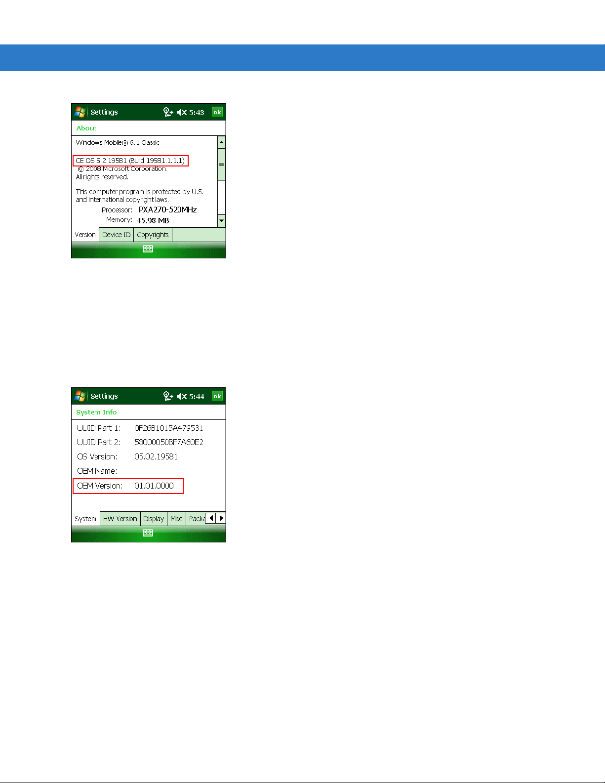
AKU Version for Windows Mobile 6.1 Devices
To determine the Adaptation Kit Update (AKU) version on a Windows Mobile 6.1 device:
Ta p
Start > Settings > System tab > About icon > Version tab.
About This Guide xiii
Hamptons
The second line lists the operating system version and the build number. The last part of the build number
represents the AKU number. For example, Build 119581.1.1.1 indicates that the device is running AKU version
1.1.1.
OEM Version on Windows Mobile 6.1 Devices
To determine the OEM software version on a Windows Mobile 6.1 device:
Start > Settings > System tab > System Information icon > System tab.
Ta p
OEM Software on Windows CE 5.0 Devices
To determine the OEM software version on a Windows CE 5.0 device:
Start > Settings > Control Panel > System Information icon > System tab.
Ta p
ZEBRA

xiv MC3000 Integrator Guide
MC3000C50B
BTExplorer Software
To determine the BTExplorer software version on a Windows Mobile 6.1 or Windows CE 5.0 device:
BTExplorer icon > Show BTExplorer> File > About.
Ta p
Fusion Software
To determine the Fusion software version on a Windows Mobile 6.1 or Windows CE 5.0 device:
Ta p
Wireless Strength icon > Wireless Status > Versions.

Chapter Descriptions
Topics covered in this guide are as follows:
•
Chapter 1, Getting Started, describes the mobile computer’s physical characteristics, how to install and
charge the batteries, remove and replace the Strap/Door Assembly and how to start the mobile computer for
the first time.
•
Chapter 2, Accessories, describes the accessories available including cradles, cables and spare battery
chargers. Accessory set up and use is also provided.
•
Chapter 3, ActiveSync, provides instructions on installing ActiveSync, setting up a partnership and
synchronizing information between the mobile computer and a host computer.
•
Chapter 4, Application Deployment for Windows CE 5.0, provides instructions for provisioning and deploying
applications on the MC3000 with WinCE 5.0.
•
Chapter 5, Application Deployment for Windows Mobile 6.1, provides instructions for provisioning and
deploying applications on the MC3000 with Windows Mobile 6.1.
•
Chapter 6, Wireless Applications, describes how to configure the wireless connection and how the wireless
LANs allow the mobile computers to communicate wirelessly with a host device.
About This Guide xv
•
Chapter 7, Staging and Provisioning, explains how to facilitate software downloads to a mobile device.
•
Chapter 8, Maintenance & Troubleshooting, includes instructions on cleaning and storing the mobile
computer, and provides troubleshooting solutions for potential problems during mobile computer operation.
•
Appendix A, Technical Specifications, includes a table listing the technical specifications for the mobile
computer.
•
Appendix B, Internet Explorer Kiosk Mode, provides instructions for configuring Internet Explorer’s Kiosk
mode.
Notational Conventions
The following conventions are used in this document:
•
The term “mobile computer” refers to the Zebra MC3000.
•
Italics are used to highlight the following:
• Chapters and sections in this and related documents
• Dialog box, window and screen names
• Drop-down list and list box names
• Check box and radio button names
• Icons on a screen.
•
Bold text is used to highlight the following:
• Key names on a keypad
• Button names on a screen.

xvi MC3000 Integrator Guide
•
Bullets (•) indicate:
• Action items
• Lists of alternatives
• Lists of required steps that are not necessarily sequential.
•
Sequential lists (e.g., those that describe step-by-step procedures) appear as numbered lists.
Related Documents and Software
The following documents provide more information about the MC3000 mobile computers.
•
MC3000 Series Quick Start Guide p/n 72-68902-xx
•
MC3090G Quick Start Guide, p/n 72-71347-xx
•
MC3000 Licensing, Patent and Regulatory Information, p/n 72-68903-xx
•
MC3000 Regulatory Guide for Windows Mobile 6, p/n 72- 72-114046-xx
•
MC3000 User Guide, p/n 72E-68899-xx
•
Application Guide for Zebra Devices, p/n 72-68901-xx
•
Microsoft® Applications for Mobile and WinCE 5.0 User Guide, p/n 72E-78456-xx
•
Microsoft® Applications for Mobile 6 User Guide, p/n 72E-108299-xx
•
Enterprise Mobility Developer Kit (EMDK) Help File, p/n 72E-38880-03
•
Windows CE Platform SDK for MC3000c50, available at: http://www.zebra.com/support
•
Enterprise Mobility Developer Kit for C (SMDK for C), available at: http://www.zebra.com/support
•
Device Configuration Package for MC3000 (DCP for MC3000), available at: http://www.zebra.com/support
•
ActiveSync software, available at: http://www.microsoft.com.
For the latest version of this guide and all guides, go to: http://www.zebra.com/support
Service Information
If you have a problem with your equipment, contact Zebra support for your region. Contact information is available
at: http://www.zebra.com/support
When contacting support, please have the following information available:
•
Serial number of the unit
.
•
Model number or product name
•
Software type and version number
Zebra responds to calls by email, telephone or fax within the time limits set forth in support agreements.
If your problem cannot be solved by Zebra Support, you may need to return your equipment for servicing and will
be given specific directions. Zebra is not responsible for any damages incurred during shipment if the approved
shipping container is not used. Shipping the units improperly can possibly void the warranty.
If you purchased your business product from a Zebra business partner, contact that business partner for support.

Chapter 1 Getting Started
Introduction
This chapter describes the mobile computer’s physical characteristics, how to install and charge the batteries, how
to remove and replace the Strap/Door Assembly and how to start the mobile computer for the first time.
Unpacking the Mobile Computer
Carefully remove all protective material from around the mobile computer and save the shipping container for later
storage and shipping. Verify that the equipment listed below is included:
•
MC3000 mobile computer
•
Strap/Door Assembly, attached to the mobile computer
•
Stylus
•
Regulatory Guide
•
Quick Start Guide (poster).
Depending on the configuration ordered, the mobile computer shipping container or additional shipping container
may include:
•
Standard Battery (lithium-polymer)
•
Extended Life Battery (lithium-ion)
•
Cable(s)
•
Power Supply
•
Cradles.
Inspect the equipment for damage. If any equipment is missing or damaged, contact Zebra Support immediately.
See page xvi for contact information.

1 - 2 MC3000 Integrator Guide
Accessories
Table 1-1 lists the MC3000 accessories.
Table 1-1 MC3000 Accessories
Accessory Description
Single Slot Serial/USB Cradle Charges the mobile computer main battery and a spare battery, and
Four Slot Charge Only Cradle Charges up to four mobile computers.
Four Slot Ethernet Cradle Charges up to four mobile computers and provides Ethernet
Four Slot Spare Battery Charger Charges up to four mobile computer spare batteries.
Power Supply Country specific and accessory specific, power supply.
USB Client Charge Cable Provides USB client communication capabilities and charges the mobile
synchronizes the mobile computer with a host computer through either a
serial or USB connection.
communications.
computer.
Serial (RS232) Charge Cable Provides RS232 communication capabilities and charges the mobile
computer.
O’Neil Printer Cable Provides printer specific communication capabilities (provided by O’Neil).
Zebra Printer Cable Provides printer specific communication capabilities (provided by Zebra).
Monarch Printer Cable Provides printer specific communication capabilities (provided by
Monarch).
Single Slot Cradle RS232 Cable Provides serial host communication capabilities and charges the mobile
computer.
Single Slot Cradle USB Cable Provides USB communication capabilities and charges the mobile
computer.
MC3000 Universal Battery Charger
Adapter (UBC)
Stylus Performs pen and mouse functions.
Plastic Holster Provides a clip on holder for the mobile computer.
Fabric Holster Provides a soft, clip on holder and a shoulder strap for the mobile
Symbol Mobility Developer Kit for C A development tool used to create native C and C++ applications for all
Adapts the UBC for use with MC3000 batteries.
computer.
Zebra mobile computers running the Microsoft Windows CE operating
system. Available at: http://www.zebra.com/support.
Device Configuration Package (DCP)
for MC3000
A development tool used to create and download hex images that
represent flash partitions to the mobile computer. Available at:
http://www.zebra.com/support.
Parts
Keypad
Indicator
LED Bar
Screen
Scan LED Indicator
(red/green)
Power
Scan Buttons
MC3000R
MC3000S
Rotating Scan
Turret
Beeper or
Receiver
(optional)
Microphone
(optional)
Scan LED
Indicators
(red/green)
Charge LED
Indicator
(amber)
Getting Started 1 - 3
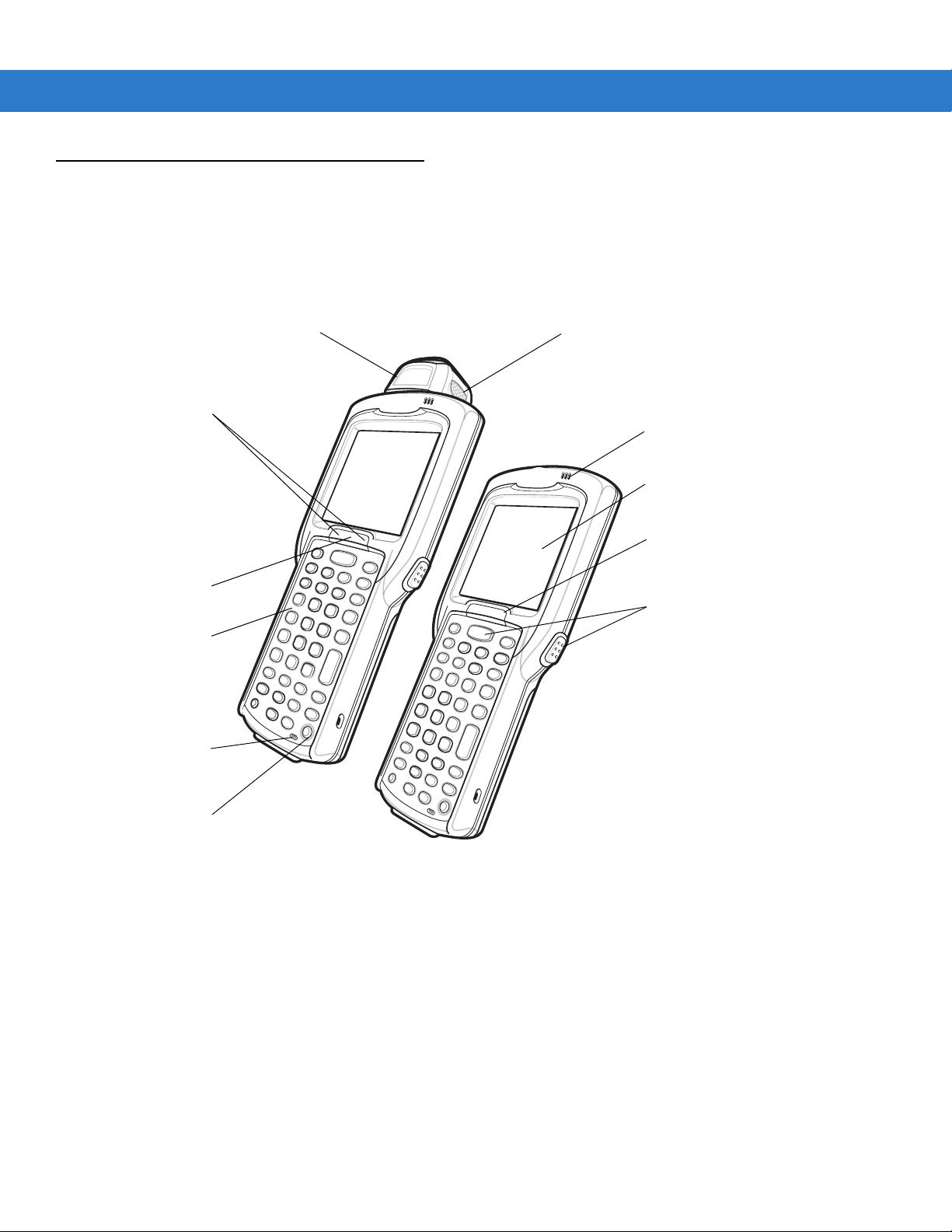
There are three versions of the MC3000 mobile computers, the MC3000 1D/2D Imager (MC3000S or MC3090S),
the MC3000 Laser with Rotating Scan Turret (MC3000R or MC3090R) and the MC3090 Gun (MC3090G). For
more information on the Rotating Scan Turret, see Figure 1-3 on page 1-4.
Figure 1-1
MC3000 Imager (MC3000S) and MC3000 Laser (MC3000R) Mobile Computers (front view)

1 - 4 MC3000 Integrator Guide
Strap/Door
Assembly
Scan Window
Stylus
MC3000S
MC3000R
Latches
Strap/Door
Assembly
Screws
Stylus
Holder
Headset Jack
(optional)
Headset Jack
(optional)
Scan Window
Position Stop
Position Stop
Position Stop
Figure 1-2
Rotating Scan Turret
MC3000 Imager (MC3000S) and MC3000 Laser (MC3000R) Mobile Computers (back view)
The MC3000R mobile computer features a Rotating Scan Turret with three position stops. This feature offers
greater scanning flexibility.
Figure 1-3
Rotating Scan Turret

Getting Started 1 - 5
Keypad
Indicator LED Bar
Display
Power
Scan Button
Beeper
Trigger
Scan LED
Indicators
(red/green)
Charge LED
Indicator
(amber)
Scan LED
Indicator
(red/green)
Figure 1-4
MC3090G Mobile Computer

1 - 6 MC3000 Integrator Guide
Mobile Computer Startup
To start using the mobile computer:
•
Install the main battery.
•
Charge the main battery and the backup battery.
•
Start the mobile computer.
Install Main Battery
If the main battery is charged, the mobile computer can be used immediately. If the main battery is not charged,
see Battery Charging on page 1-8. To remove the main battery, see Main Battery Removal on page 1-13.
To install the main battery:
1. Rotate the latches to the open position.
CAUTION Do not lift up on the Latches when removing the Strap/Door Assembly. Lift up on the Hand Strap only.
2. Pull on the strap to lift the Strap/Door Assembly off, bottom first.
CAUTION On the MC3090G battery, do not remove the battery pull tab. The pull tab is for enabling easy battery
removal from the device.
3. Insert the battery into the slot, bottom first and press the battery gently into the slot. The battery clip locks the
battery into place.
4. With the latches in the open position, replace the Strap/Door Assembly, top first and press to close.
5. Rotate the latches (to the lock position) to lock the Strap/Door Assembly in place.

Getting Started 1 - 7
Battery Clip
Strap/Door
Assembly
Battery
Battery Slot
Hand Strap
Latches
5
2
0.5 in.
(12.7 mm)
3
Strap/Door
Assembly
Battery
Hand Strap
Latches
Strap/Door
Assembly
Figure 1-5
1
Main Battery Installation
Figure 1-6
Main Battery Installation (MC3090G)

1 - 8 MC3000 Integrator Guide
Battery Charging
CAUTION Ensure that you follow the guidelines for battery safety described in Battery Safety Guidelines on page 8-1.
Use the mobile computer cradles, cables and spare battery chargers to charge the mobile computer main battery.
The main battery can be charged before insertion into the mobile computer or after it is installed. There are two
main batteries for the MC3000, the Standard Battery and the Extended Life Battery. Either battery can be used, but
the Extended Life Battery requires a different Strap/Door Assembly. Use one of the spare battery chargers to
charge the main battery (out of the mobile computer) or one of the cradles to charge the main battery while it is
installed in the mobile computer.
Before using the mobile computer for the first time, fully charge the main battery until the amber Charge LED
Indicator remains lit (see Table 1-2 on page 1-9 for charge status indications). The Standard Battery fully charges in
less than four hours and the Extended Life Battery fully charges in less than six hours.
The mobile computer is equipped with a memory backup battery which automatically charges from the main
battery whether or not the mobile computer is operating or is in suspend mode. The memory backup battery retains
data in memory for at least 30 minutes when the mobile computer’s main battery is removed or fully discharged.
When the mobile computer is used for the first time or after the memory backup battery has fully discharged, the
memory backup battery requires approximately 15 hours to fully charge. Do not remove the main battery from the
mobile computer for 15 hours to ensure that the memory backup battery fully charges. If the main battery is
removed from the mobile computer or the main battery is fully discharged, the memory backup battery completely
discharges in several hours.
When the main battery reaches a very low battery state, the combination of main battery and backup battery
retains data in memory for at least 72 hours.
NOTE Do not remove the main battery within the first 15 hours of use. If the main battery is removed before the
backup battery is fully charged, data may be lost.
Batteries must be charged within the 32° to 104° F (0° to +40° C) ambient temperature range.
The following accessories can be used to charge the batteries:
•
Cradles (and a power supply):
• Single Slot Serial/USB Cradle
• Four Slot Cradles.
•
Cables (and a power supply):
• USB Client Charge Cable
• Serial (RS232) Charge Cable.
•
Spare Battery Chargers (and a power supply):
• Single Slot Serial/USB Cradle
• Four Slot Spare Battery Charger
• Universal Battery Charger (UBC) Adapter.
To charge the mobile computer using the cradles:
1. Insert the mobile computer into a cradle. See Chapter 2, Accessories for accessory information.
Getting Started 1 - 9
2. The mobile computer starts to charge automatically. The amber Charge LED Indicator indicates the charge
status. See Table 1-2 on page 1-9 for charging indications.
To charge the mobile computer using the cables:
1. Connect the MC3000 Communication/Charge Cable to the appropriate power source and connect to the
mobile computer. See Chapter 2, Accessories for accessory setup.
2. The mobile computer starts to charge automatically. The amber Charge LED Indicator indicates the charge
status. See Table 1-2 on page 1-9 for charging indications.
Table 1-2 Mobile Computer LED Charge Indicators
LED Indication
Off Mobile computer not placed correctly in the cradle; cable not connected correctly;
charger is not powered.
Fast Blinking Amber Error in charging; check placement of the mobile computer.
Slow Blinking Amber Mobile computer is charging.
Solid Amber Charging complete.
Note: When the battery is initially inserted in the mobile computer, the amber LED
flashes once if the battery power is low or the battery is not fully inserted.
Spare Battery Charging
There are three accessories that can be used to charge a spare battery:
•
Single Slot Serial/USB Cradle
•
Four Slot Spare Battery Charger
•
UBC Adapter.
To charge a spare battery:
1. Connect the charging accessory to the appropriate power source. See Chapter 2, Accessories for setup
instructions.
2. Insert the spare battery into the spare battery charging slot and gently press down on the battery to ensure
proper contact.
The battery starts to charge automatically. The charge LED Indicator lights to indicates the charge status. See
Chapter 2, Accessories for charging indications. The Standard Battery usually fully charges in less than four hours
and the Extended Life Battery usually fully charges in less than six hours.
Stylus
Use the stylus to select items and enter information on the screen. The stylus functions as a pen and a mouse. Tap
the touch screen once with the stylus to select options and open menu items.
To remove the stylus, slide the stylus out of the stylus holder. To store the stylus, push the stylus back into the
stylus holder.

1 - 10 MC3000 Integrator Guide
OR
Calibration Screen Confirm Calibration
Resave Screen
Starting the Mobile Computer
When the mobile computer is powered on for the first time, it initializes. The Zebra Splash screen appears for a
short period of time, followed by the
Calibration screen.
Figure 1-7
After the calibration procedure is performed the factory default settings launch the
specific shells may provide application specific windows instead of the
Zebra Splash Screen
Demo window. Application
Demo window. These screens also appear
when a cold boot is performed.
If the mobile computer does not power on, see Resetting the Mobile Computer on page 1-11.
Calibration Screen
Use the Calibration screen to align the touch screen:
1. Remove the stylus from the stylus holder.
2. Carefully press and briefly hold the tip of stylus on the center of the Calibration screen target. Repeat the
procedure as the target moves and stops at different locations on the screen. This enters the new calibration
settings.
Figure 1-8
3. Once all of the new calibration settings are input, the Confirm Calibration Resave screen appears. Tap the
Calibration Screen
screen within 30 seconds to save the new calibration settings or allow the 30 second timer to expire and the
new calibration settings are not saved.
Getting Started 1 - 11
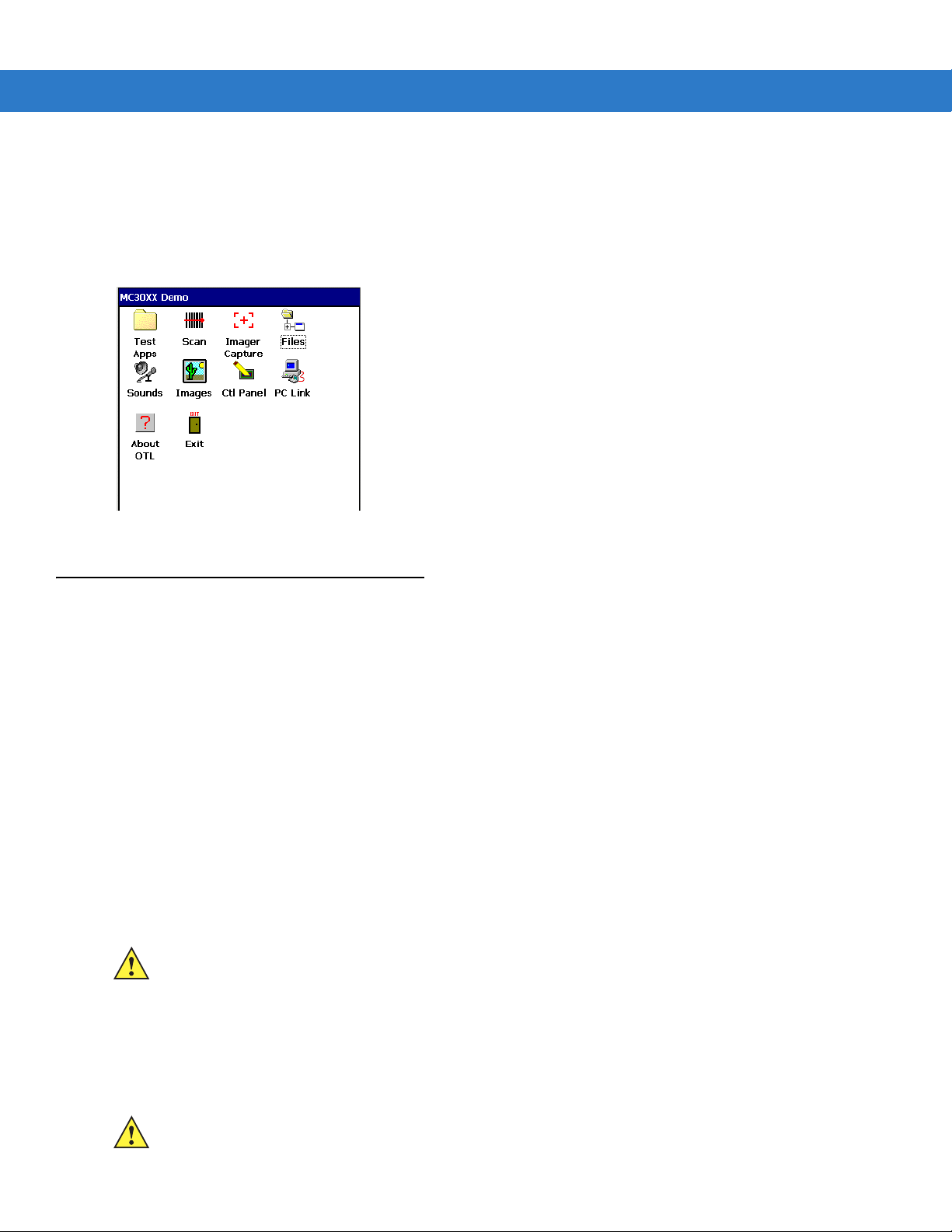
Demo Window
The Demo window is the factory default menu. On initial power up (or on a warm or cold boot) the Demo window
appears. These sample/demo applications are intended to be used by application developers as application
development examples. These applications were not developed to support end users. Refer to the Zebra
Application Guide for information about the
Demo window applications.
Figure 1-9
Demo Window
Resetting the Mobile Computer
Windows CE Devices
If the mobile computer stops responding to input, reset it. There are two reset functions, warm boot and cold boot.
A warm boot restarts the mobile computer by closing all running programs. All data that is not saved is lost.
A cold boot also restarts the mobile computer, but erases all stored records and entries from RAM. In addition it
returns formats, preferences and other settings to the factory default settings.
Perform a warm boot first. If the mobile computer still does not respond, perform a cold boot.
Performing a Warm Boot
To perform a warm boot on 28, 38 and 48-key keypad configurations:
1. Press and simultaneously hold 7, 9 and Power. Do not hold down any other keys or buttons.
2. As the mobile computer initializes MC3000 demo window appears.
CAUTION Files that remain open during a warm boot may not be retained.
To perform a warm boot on 20-key keypad configurations:
1. Press and simultaneously hold the 7 and 9 keys and the press the MENU and Fn keys. Do not hold down any
other keys or buttons.
2. As the mobile computer initializes MC3000 demo window appears.
CAUTION Files that remain open during a warm boot may not be retained.

1 - 12 MC3000 Integrator Guide
Performing a Cold Boot
A cold boot restarts the mobile computer and erases all user stored records and entries from RAM. Never perform
a cold boot unless a warm boot does not solve the problem.
CAUTION Cold boot resets the mobile computer, to the default settings. All added applications and all stored data are
removed. Do not cold boot without support desk approval.
To perform a cold boot 28, 38 and 48-key keypad configurations:
1. Simultaneously press and then release the 1, 9 and Power keys. Do not hold down any other keys or buttons.
As the mobile computer initializes, the Zebra splash window, Figure 1-7 on page 1-9, appears for about a
minute.
2. Calibrate the touch screen. See Calibration Screen on page 1-10 to calibrate the mobile computer screen.
To perform a cold boot on 20-key keypad configurations:
1. Simultaneously press and then release the 1 and 9, MENU and Fn keys. Do not hold down any other keys or
buttons. As the mobile computer initializes, the Zebra splash window, Figure 1-7 on page 1-9, appears for
about a minute.
2. Calibrate the touch screen. See Calibration Screen on page 1-10 to calibrate the mobile computer screen.
Windows Mobile 6.1 Devices
There are two reset functions, warm boot and cold boot.
•
A warm boot restarts the mobile computer and closes all running programs.
•
A cold boot also restarts the mobile computer and closes all running programs but also resets the
Real-Time-Clock (RTC).
Data saved in flash memory or a memory card is not lost. Perform a warm boot first. This restarts the mobile
computer and saves all stored records and entries. If the mobile computer still does not respond, perform a cold
boot.
Performing a Warm Boot
To perform a warm boot on 28, 38 and 48-key keypad configurations:
1. Press and simultaneously hold 7, 9 and Power. Do not hold down any other keys or buttons.
2. As the mobile computer initializes Today screen appears.
Performing a Cold Boot
A cold boot restarts the mobile computer. The operating system and all applications are restarted. File storage is
preserved. The Real-Time-Clock (RTC) resets. Only perform a cold boot if a warm boot does not solve the
problem.
1. To perform a cold boot 28, 38 and 48-key keypad configurations, simultaneously press and then release the 1,
9 and Power keys. Do not hold down any other keys or buttons.
2. As the mobile computer initializes, the splash window, Figure 1-7 on page 1-9, appears for about a minute.

Waking the Mobile Computer
The wakeup conditions define what actions wake up the mobile computer after it has gone into suspend mode. The
mobile computer can go into suspend mode by either pressing the Power button or automatically by Control Panel
time-out settings. These settings are configurable and the factory default settings are shown in Table 1-3.
Table 1-3 Wakeup Default Settings
Condition for Wakeup Power Button Automatic Time-out
AC power is applied. No Yes
Mobile computer is inserted into a cradle. No Yes
Mobile computer is removed from a cradle. No Yes
Mobile computer is connected to a serial device. No Yes
Mobile computer is connected to a USB device. No Yes
Mobile computer is disconnected from a USB device. No Yes
A key is pressed. No Yes
Getting Started 1 - 13
The scan triggered is pressed. No Yes
The screen is touched. No No
Wireless LAN activity is detected. No No
Main Battery Removal
Before removing the main battery, turn off the mobile computer.
To remove the main battery:
1. Rotate the latches to the open position.
CAUTION Do not lift up on the Latches when removing the Strap/Door Assembly. Lift up on the Hand Strap only.
2. Lift the Hand Strap to lift the Strap/Door Assembly off, bottom first.
CAUTION On the MC3090G battery, do not remove the battery pull tab. The pull tab is for enabling easy battery
removal from the device.
3. Release battery:
a. On the MC3000S/R, release the battery clip (at the top of the battery) and lift the battery out top first.
b. On the MC3090G, pull the battery pull tab to unclip the battery and lift the battery out top first. If the battery
does not have a pull tab, use the stylus to unclip the battery and then lift the battery.

1 - 14 MC3000 Integrator Guide
Battery Clip
Latches
Strap/Door
Assembly
Battery
Hand Strap
4
4
Strap/Door
Assembly
Latches
Battery Pull Tab
Battery with Pull Tab Battery without Pull Tab
Figure 1-10
Main Battery Removal (MC3000S/R)
1
0.5 in.
(12.7 mm)
2
3
Figure 1-11
Main Battery Removal (MC3090G)

Strap/Door Assembly Removal and Replacement
Strap/Door
Assembly
Latches
Screws
#00 Phillips
Screwdriver
Mounting
Clip
Strap Loop
Mounting
Clip
Hand Strap
The Strap/Door Assembly consists of a hand strap and the battery door. There are two versions of this assembly,
one for the Standard Battery and one for the Extended Life Battery. Before removing the Strap/Door Assembly,
press the red
To remove the Strap/Door Assembly:
1. Rotate the latches to the open position.
2. Lift the Hand Strap to lift the Strap/Door Assembly off, bottom first.
3. Use a #00 Phillips screwdriver to remove the screws.
4. Lift the mounting clip.
5. Slide the mounting clip out of the strap loop.
Reverse the procedure to replace the Strap/Door Assembly.
Power button to turn off the screen and set the mobile computer to suspend mode.
CAUTION Do not lift up on the Latches when removing the Strap/Door Assembly. Lift up on the Hand Strap only.
Getting Started 1 - 15
Figure 1-12
Strap/Door Removal and Replacement

1 - 16 MC3000 Integrator Guide
Strap/Door
Assembly
Latches
Button
Loop
Strap/Door Assembly Removal and Replacement (MC3090G)
The Strap/Door Assembly consists of a hand strap and the battery door. Before removing the Strap/Door Assembly,
press the red
To remove the Strap/Door Assembly:
1. Slip the button through the loop.
2. Remove loop section from handle.
3. Rotate the latches to the open position.
4. Lift the Hand Strap to lift the Strap/Door Assembly off, bottom first.
Reverse the procedure to replace the Strap/Door Assembly.
Power button to turn off the screen and set the mobile computer to suspend mode.
CAUTION Do not lift up on the latches when removing the Strap/Door Assembly. Lift up on the Hand Strap only.
Figure 1-13
0.5 in.
(12.7 mm)
Strap/Door Removal and Replacement (MC3090G)

File System Directory Structure
The mobile computer directory structure displays all of the file folders. The pre-installed folders are in flash file
system memory and optional removable storage devices (SD storage cards).
Getting Started 1 - 17
Figure 1-14
•
Application and Platform folders are located in flash file system memory.
•
The Windows, Program Files, profiles, and My Documents folders are composites, RAM based folders
generated from ROM.
•
The Network folder is a link to file systems mapped using the network re-director. The files do not physically
reside on the mobile computer.
•
The Tem p and Recycled folders typically contain RAM based files.
NOTE All files copied to the RAM based folders are lost after a cold boot.
Flash Storage
In addition to the RAM based storage the mobile computer is also equipped with a non-volatile flash based storage
area which can store data (partitions) that can not be corrupted by a cold boot. See Flash Storage on page 6-16 for
a detailed discussion.
Mobile Computer Directory Structure

1 - 18 MC3000 Integrator Guide
Launching Applications
The Application/Startup folder is used to launch programs automatically when the mobile computer is powered on
or after a warm or cold boot.
NOTE The Windows/Startup folder is not supported.
There are two ways to launch programs automatically:
1. Place the executable in the Startup folder (located in the Application folder).
2. Place a .run file in the Startup folder. A .run file is a simple text file that contains the path to an application as
well as the name of the application to run.
Refer to the SMDK Help File included with the SMDK for more information on the
Startup folder.

Chapter 2 Accessories
Introduction
The MC3000 accessories provide a variety of product support capabilities. Accessories include cradles, cables,
spare battery chargers and SD cards.
Cradles
•
Single Slot Serial/USB cradle charges the mobile computer main battery and/or a spare battery. It also
synchronizes the mobile computer with a host computer through either a serial or a USB connection.
•
Four Slot Charge Only cradle charges up to four mobile computers.
•
Four Slot Ethernet cradle charges up to four mobile computers and provides Ethernet communication
capability.
Spare Battery Chargers
•
Four Slot Spare Battery Charger charges up to four MC3000 spare batteries.
•
UBC Adapter adapts the UBC2000 for use with the MC3000 spare batteries.
Cables
The cables snap on to the mobile computer and are used to connect external devices to the mobile computer.
•
USB client charge cable
•
Serial (RS232) charge cable
•
O’Neil printer cable (provided by O’Neil)
•
Zebra printer cable (provided by Zebra)
•
Monarch printer cable (provided by Monarch).
SD Card
The SD card provides additional storage capacity for the mobile computer.

2 - 2 MC3000 Integrator Guide
Single Slot Serial/USB Cradle
CAUTION Ensure that you follow the guidelines for battery safety described in Battery Safety Guidelines on page 8-1.
This section describes how to set up and use the Single Slot Serial/USB cradle. For cradle setup, see Figure 2-2.
For communications setup procedures, see USB Connection Setup on page 2-34 and/or Serial Communication
Setup on page 2-30.
The Single Slot Serial/USB cradle:
•
Provides 5.4VDC power for operating the mobile computer, charging the battery and charging a spare
battery.
•
Provides a serial port and a USB port (mini AB receptacle) for data communication between the mobile
computer and a host computer or other serial devices (e.g., a printer).
•
Synchronizes information between the mobile computer and a host computer. With customized or third party
software, it can also synchronize the mobile computer with corporate databases.
•
Provides serial connection through the serial pass-through port for communication with a serial device, such
as a host computer. For communication setup procedures, see Serial Communication Setup on page 2-30.
•
Provides USB connection through the USB pass-through port for communication with a USB device, such as
a host computer. For communication setup procedures, see USB Connection Setup on page 2-34.
CAUTION Use only a Zebra approved power supply output rated 12 VDC and minimum 3.3 A. Use of an
alternative power supply will void the product warranty and may cause product damage. See the
MC3000 User Guide for the power supply regulatory compliance statement.

Setup
USB Port
USB Port
Serial Port
DC Cable
Power Supply
Power Port
Serial Cable
Serial Port
USB Cable
AC Line Cord
Accessories 2 - 3
NOTE The cradle requires a dedicated port on the host computer. Select either serial or USB for communications, do
not connect the cradle to both serial and USB ports.
Figure 2-1
Battery Charging
Single Slot Serial/USB Cradle Setup
The Single Slot Serial/USB cradle can charge the mobile computer main battery and a spare battery
simultaneously.
To charge the mobile computer:
1. Connect the Single Slot Serial/USB cradle to a Zebra approved power source.
2. Slide the mobile computer into the mobile computer slot. The amber Charge LED Indicator indicates the mobile
computer battery charging status. The Standard Battery charges in less than four hours and the Extended Life
Battery charges in less than six hours. See Table 2-1 for charging status indications.

2 - 4 MC3000 Integrator Guide
Scan/Charge
Indicator
LED Bar
Mobile
Computer Slot
Spare
Battery
Spare Battery
Charging LED
Power Port
Serial Port
USB Port
Spare
Battery
Charging
Slot
Battery
Clip
Charge LED
Indicator
(amber)
LED Charge Indications
Figure 2-2
3. When charging is complete, remove the mobile computer from the mobile computer slot.
Single Slot Serial/USB Cradle
To charge a spare battery:
1. Connect the Single Slot Serial/USB cradle to a Zebra approved power source.
2. Insert the spare battery into the spare battery charging slot, bottom first, and pivot the top of the battery down
onto the contact pins.
3. Gently press down on the battery to ensure proper contact.
4. The cradle Spare Battery Charging LED indicates the spare battery charging status. The Standard Battery
usually charges in less than four hours and the Extended Life Battery usually charges in less than six hours.
See Table 2-1 for charging status indications.
5. When charging is complete, press the battery clip and lift the battery out of the slot.
The Single Slot Serial/USB cradle uses the amber Charge LED Indicator to indicate MC3000 battery charging
status and the Spare Battery Charging LED to indicate spare battery charging status. See Table 2-1 for charging
status indications.

Accessories 2 - 5
Table 2-1
Mobile Computer Charging (LED on mobile computer)
Off Mobile computer not placed correctly in the cradle; cable not connected correctly;
Fast Blinking Amber Error in charging; check placement of mobile computer.
Slow Blinking Amber Mobile computer is charging.
Solid Amber Charging complete.
Spare Battery Charging (LED on cradle)
Off No spare battery in slot; spare battery not placed correctly; cradle is not powered.
Fast Blinking Amber Error in charging; check placement of spare battery.
Slow Blinking Amber Spare battery is charging.
Solid Amber Charging complete.
LED Charging Status Indicators
LED Indication
charger is not powered.
Note: When the battery is initially inserted in the mobile computer, the amber LED
flashes once if the battery power is low or the battery is not fully inserted.
Communication Setup
To connect the Single Slot Serial/USB cradle to a serial or USB device:
1. Connect Single Slot Serial/USB cradle cable to the communications port.
2. Slide the mobile computer into the mobile computer slot. The amber Charge LED Indicator indicates the mobile
computer battery charging status and that the mobile computer is seated in the cradle. For more information on
communications setup procedures, see USB Connection Setup on page 2-34 and/or Serial Communication
Setup on page 2-30.

2 - 6 MC3000 Integrator Guide
AC Line Cord
Power Supply
DC Cable
Power Port
Four Slot Charge Only Cradle
CAUTION Ensure that you follow the guidelines for battery safety described in Battery Safety Guidelines on page 8-1.
The Four Slot Charge Only cradle:
•
Provides 5.4VDC power for operating the mobile computer and charging the battery.
•
Simultaneously charges up to four mobile computers.
CAUTION Use only a Zebra approved power supply output rated 12 VDC and minimum 9 A. Use of an alternative
power supply will void the product warranty and may cause product damage. See the MC3000 User
Guide for the power supply regulatory compliance statement.
Setup
Connect the Four Slot Charge Only cradle to a Zebra approved power source.
Figure 2-3
Four Slot Charge Only Cradle, Setup
Battery Charging
The Four Slot Charge Only cradle can charge up to four mobile computers simultaneously.
To charge the mobile computer:
1. Connect the Four Slot Charge Only cradle to a Zebra approved power source.
2. Slide the mobile computer into the mobile computer slot.

Accessories 2 - 7
Power LED
Scan/Charge
Indicator LED Bar
Mobile Computer
Slot
Charge LED
Indicator (amber)
Figure 2-4
3. The mobile computer amber Charge LED Indicator indicates the mobile computer battery charging status. The
Four Slot Charge Only Cradle
Standard Battery usually charges in less than four hours and the Extended Life Battery usually charges in less
than six hours. See Table 2-1 on page 2-5 for charging status indications.
4. When charging is complete, remove the mobile computer from the cradle.
Power LED
The green Power LED lights to indicate that the Four Slot Charge Only cradle is connected to a power source.
LED Charge Indications
The Four Slot Charge Only cradle uses the amber Charge LED Indicator to indicate battery charging status. See
Table 2-1 on page 2-5 for charging status indications.

2 - 8 MC3000 Integrator Guide
Power Port
Ethernet Port 1
Ethernet Switch
Connection
Four Slot Ethernet Cradle
CAUTION Ensure that you follow the guidelines for battery safety described in Battery Safety Guidelines on page 8-1.
This section describes how to set up and use a Four Slot Ethernet cradle with the mobile computer.
The Four Slot Ethernet cradle:
•
Provides 5.4 VDC power for operating the mobile computer.
•
Connects the mobile computer (up to four) to an Ethernet network.
You cannot ActiveSync using the Four Slot Ethernet cradle. To ActiveSync with a host computer, use the SIngle
Slot Serial/USB cradle.
CAUTION Use only a Zebra approved power supply output rated 12 VDC and minimum 9 A. Use of an alternative
power supply will void the product warranty and may cause product damage. See the MC3000 User Guide
for the power supply regulatory compliance statement.
Setup
Connect the Ethernet cradle (Ethernet port 1) to an Ethernet hub or a port on the host device. Connect the Ethernet
cradle (power port) to a Zebra approved power supply.
Figure 2-5
Ethernet Cradle Drivers (Windows CE 5.0)
The Ethernet cradle drivers are pre-installed on the MC3000 and initiate automatically when the MC3000 is placed
in a properly connected Four Slot Ethernet cradle.
When the mobile computer is inserted into the Four Slot Ethernet cradle, the LAN icon indicates that the mobile
computer is connected to a network.
Four Slot Ethernet Cradle Connection

Accessories 2 - 9
LAN Icon
PHOTONWirelessLANDriver
Double-tap the LAN icon to open the LANNDS1 window. This window display the TCP/IP information for the mobile
computer.
Figure 2-6
LANNDS1 Window
Ethernet Cradle Drivers (Windows Mobile 6.1)
The MC3000 includes Ethernet cradle drivers that initiate automatically when you place the MC3000 in a properly
connected Four Slot Ethernet cradle. After inserting the MC3000, configure the Ethernet connection:
1. Ta p Start > Settings > Connections tab >WiFi icon. The Configure Network Adapters window appears.
Figure 2-7
2. In the My network card connects to: drop-down list, select the appropriate connection.
3. In the Tap an adapter to modify settings: list, select NE2000 Compatible Ethernet Driver.
Configure Network Adapters Window
Figure 2-8
4. In the IP address window, select the appropriate radio button:
IP Address Tab

2 - 10 MC3000 Integrator Guide
Link LED
Scan/Charge Indicator LED Bar
Mobile Computer Slot
Charge LED Indicator (amber)
Speed LED
•
Use server-assigned IP address
or
•
Use specific IP address. Enter the IP address, Subnet mask, and Default gateway, as needed.
5. Tap the Name Servers tab.
Figure 2-9
6. Enter the appropriate DNS, Alt DNS, WINS, and Alt WINS server addresses.
7. Ta p ok.
8. Ta p ok to exit.
Name Servers Tab
Charging and Communication
Insert the mobile computer into a slot to begin charging and initiate communication.
Figure 2-10
Four Slot Ethernet Cradle

Accessories 2 - 11
Ethernet Port 1
Ethernet Port 2
Link LED
Speed LED
LED Charge Indications
The charge LED shows the status of the battery charging in the mobile computer. The Standard Battery usually
charges in less than four hours and the Extended Life Battery usually charges in less than six hours. See Table 2-1
on page 2-5 for charging status indications.
Speed LED
The green Speed LED lights to indicate that the transfer rate is 100 Mbps. When it is not lit it indicates that the
transfer rate is 10Mbps.
Link LED
The yellow Link LED blinks to indicate activity, or stays lit to indicate that a link is established. When it is not lit it
indicates that there is no link.
Daisychaining Ethernet Cradles
To connect several cradles to an Ethernet network, up to four (recommended maximum) Ethernet cradles may be
daisychained. The Speed LED and the Link LED on the Ethernet port 2 function in the same way as the Speed LED
and the Link LED on the front of the cradle.
To daisychain cradles:
1. Connect the first Ethernet cradle to power and to the Ethernet Switch as shown on Figure 2-5 on page 2-8.
2. Connect power to the second Ethernet cradle.
3. Connect the daisychain Ethernet cable (either straight or twisted cable can be used) between Ethernet Port 2
of the first cradle, and Ethernet Port 1 of the second cradle.
4. Connect additional cradles as described in Step 2 and Step 3. See Table 2-2 for bandwidth limitations.
Figure 2-11
Daisychaining Four Slot Ethernet Cradles
Bandwidth Considerations when Daisychaining
Each cradle added to the daisychain impacts the bandwidth allocated to each of the inserted mobile computers,
particularly when the mobile computers attempt to send and receive at data rates that exceed the bandwidth
provided to the chain (typically 100 Mbps). If a mobile computer in a daisychained cradle does not use its
bandwidth, that bandwidth is available to other inserted mobile computers.

2 - 12 MC3000 Integrator Guide
Table 2-2 shows allocated bandwidth (based on 100 Mbps) for the number of daisychained cradles, with each
mobile computer attempting transmission at the maximum data rate.
Table 2-2
Daisychained Ethernet
Cradle 1 100,000,000 20,000,000*
Cradle 2 20,000,000 4,000,000
Cradle 3 4,000,000 800,000
Cradle 4 800,000 160,000
Cradle 5** 160,000 32,000
Cradle 6** 32,000 6,400
Cradle 7** 6,400 1,280
* The maximum bandwidth capacity for the mobile computer is 12,000,000 bits/sec.
** Depending on the application, allocated bandwidth may not be adequate.
Daisychaining Bandwidth
Cradles
Bandwidth Allocation For Each
Ethernet Cradle (bits/sec)
Bandwidth Allocation For Each
Mobile Computer (bits/sec)

Wall Mount Bracket
Mounting Screws
(4)
Wall Mount Bracket
Mounting Tabs (2)
Mounting Slots
Use the optional Wall Mount Bracket to mount a four slot cradle directly to a wall. To attach the Wall Mount Bracket:
1. Use the Wall Mount Bracket as a template and mark the locations of the four mounting screws.
NOTE Use fasteners appropriate for the type of wall and the Wall Mount Bracket, mounting slots. The Wall Mount
Bracket, mounting slots are designed for a fastener with a #8 pan head.
2. Mount the fasteners to the wall. The screw heads should protrude about a half of an inch from the wall.
3. Slip the Wall Mount Bracket over the screw heads and slide the Wall Mount Bracket down over the screw
heads.
4. Tighten the screws to secure the Wall Mount Bracket to the wall.
Accessories 2 - 13
Figure 2-12
Wall Mount Bracket
To mount a four slot cradle:
1. Screw the supplied fasteners into the bottom of the four slot cradle. The screw heads should protrude about a
quarter of an inch from the cradle.

2 - 14 MC3000 Integrator Guide
Mounting Screws
(2)
Four Slot Cradle Bottom
Wall Mount Bracket
Screw Slots
Power Supply Well
Figure 2-13
2. Align the Wall Mount Bracket mounting tabs with the mounting slots in the back of the four slot cradle. Slip the
Cradle Mounting Screws
two mounting tabs into mounting slots.
3. Swing the four slot cradle down onto the mounting bracket and align the mounting screws so that they fit into
the screw slots.
Figure 2-14
4. Tighten the mounting screws to secure the four slot cradle to the Wall Mount Bracket.
Wall Mount Bracket

Accessories 2 - 15
Figure 2-15
5. Connect the power (see Figure 2-3 on page 2-6). The power supply should be located in the power supply well.
Mounting Screws

2 - 16 MC3000 Integrator Guide
Power Port
DC Cable
Power
Supply
AC Cord
Four Slot Spare Battery Charger
CAUTION Ensure that you follow the guidelines for battery safety described in Battery Safety Guidelines on page 8-1.
The Four Slot Spare Battery Charger simultaneously charges up to four spare batteries.
CAUTION Use only a Zebra approved power supply output rated 12 VDC and minimum 3.3 A. Use of an
alternative power supply will void the product warranty and may cause product damage. See the
MC3000 User Guide for the power supply regulatory compliance statement.
Setup
Connect the Four Slot Spare Battery Charger to a Zebra approved power source.
Figure 2-16
Spare Battery Charging
To charge up to four MC3000 spare batteries:
1. Insert the spare battery into the spare battery charging slot, bottom first.
2. Pivot the top of the battery down onto the contact pins.
Four Slot Spare Battery Charger Setup

Accessories 2 - 17
Power Supply
Spare
Batteries
Spare
Battery
Charging
Slot
Spare Battery
Charging
LEDs (4)
Battery
Clip
1
2
Figure 2-17
3. Gently press down on the battery to ensure proper contact. The Standard Battery usually charges in less than
Four Slot Spare Battery Charger
four hours and the Extended Life Battery usually charges in less than six hours. See Table 2-1 on page 2-5 for
charging status indications.
4. When charging is complete, press the battery clip and lift battery out of the slot.
LED Charge Indications
The Spare Battery Charging LEDs indicate the spare battery charging status. The Spare Battery Charging LEDs
are arranged in the same pattern as the spare battery charging slots so that the charging status of each battery can
be identified. See Table 2-1 on page 2-5 for charging status indications.

2 - 18 MC3000 Integrator Guide
Cables
This section describes how to setup and use the cables. The cables are available with a variety of connection
capabilities.
The following MC3000 Communication/Charge cables are available:
•
Serial (RS232) Charge cable (9-pin D female with power input receptacle)
•
USB Client Charge cable (standard-A connector and a barrel receptacle for power).
CAUTION Use only a Zebra approved power supply output rated 5.4 VDC and minimum 3 A. Use of an
alternative power supply will void the product warranty and may cause product damage. See the
MC3000 User Guide for the power supply regulatory compliance statement.
The following printer cables are available directly from the printer manufacturer:
•
O’Neil printer cable
•
Zebra printer cable.
•
Monarch printer cable.
Figure 2-18
The MC3000 Communication/Charge cables:
•
•
•
•
Dedicated printer cables, provide communication with a dedicated printer.
Cables (MC3000 Connector)
Provide the mobile computer with operating and charging power when used with the Zebra approved power
supply.
Synchronize information between the mobile computer and a host computer. With customized or third party
software, it can also synchronize the mobile computer with corporate databases.
Provide serial connection through the serial pass-through port for communication with a serial device, such
as a host computer. For communication setup procedures, see Serial Communication Setup on page 2-30.
Provide USB connection through the USB pass-through port for communication with a USB device, such as
a host computer. For communication setup procedures, see USB Connection Setup on page 2-34.

Accessories 2 - 19
USB Host Cable
Mini-B Connector
MC3000 Connector
Power Input
Barrel
Connector
Serial (RS232)
Cable
USB Client Cable
Standard-A
Connector
Power Input
Connector
Top View
Setup
The MC3000 Communication/Charge cables can connect with a serial/USB device, such as a printer or host
computer, through its serial or USB port.
Battery Charging
LED Charge Indications
Communication Setup
Figure 2-19
MC3000 Communication/Charge Cables
The MC3000 Communication/Charge cables can charge the mobile computer battery and supply operating power.
To charge the mobile computer battery:
1. Connect the MC3000 Communication/Charge cable power input connector to the Zebra approved power
source.
2. Attach the bottom of the mobile computer to the MC3000 connector and gently press in until the snaps latch on
the mobile computer.
3. The mobile computer amber Charge LED Indicator indicates the mobile computer battery charging status. The
Standard Battery usually charges in less than four hours and the Extended Life Battery usually charges in less
than six hours. See Table 2-1 on page 2-5 for charging status indications.
4. When charging is complete, remove the cable by gently pulling the mobile computer and the cable apart until
the snaps release the mobile computer.
The MC3000 Communication/Charge cables use the amber Charge LED Indicator to indicate the MC3000 battery
charging status. See Table 2-1 on page 2-5 for charging status indications.
To connect the MC3000 Communication/Charge cables to a serial or USB device:
1. Connect serial/USB end of the MC3000 Communication/Charge cable into the communications port.
2. Connect the MC3000 connector end to the MC3000 Communication/Charge cable to the mobile computer. For
more information on communications setup procedures, see USB Connection Setup on page 2-34 and/or
Serial Communication Setup on page 2-30.

2 - 20 MC3000 Integrator Guide
Power Supply
AC Line Cord
DC Cable
Power Port
Universal Battery Charger (UBC) Adapter
CAUTION Ensure that you follow the guidelines for battery safety described in Battery Safety Guidelines on page 8-1.
The UBC Adapter can be used with a power supply as a standalone spare battery charger or it can be used with
the four station UBC2000 to simultaneously charge up to four spare batteries. For additional information on the
UBC 2000, refer to the UBC 2000 Quick Reference Guide, p/n 70-33188-xx.
CAUTION Use only a Zebra approved power supply output rated 15 VDC and minimum 1.5 A. Use of an
alternative power supply will void the product warranty and may cause product damage. See the
MC3000 User Guide for the power supply regulatory compliance statement.
Setup
Connect the UBC Adapter to a Zebra approved power source.
Figure 2-20
UBC Adapter Setup
Spare Battery Charging
To charge spare batteries:
1. Insert the spare battery into the spare battery charging slot, bottom first.
2. Pivot the top of the battery down onto the contact pins.

Accessories 2 - 21
UBC Adapter
Battery
Battery Clip
Spare Battery
Charging Slot
2
1
POWER
READY or STANDBY or FAU LT
CHARGING
(Green) (Flashing Yellow) (Solid Yellow)
(Solid Yellow)
Figure 2-21
UBC Adapter Battery Insertion
3. Gently press down on the battery to ensure proper contact. The Standard Battery usually charges in less than
four hours and the Extended Life Battery usually charges in less than six hours. See Table 2-3 for charging
status indications.
4. When charging is complete, press the battery clip and lift the battery out of the slot.
UBC Adapter LED Charge Indications
The UBC Adapter charging LEDs indicate the battery charging status.
Figure 2-22
UBC Adapter LEDs
Table 2-3
UBC Adapter Charge LED Status Indications
LED Indication Description
POWER Green Power is connected to the UBC Adapter.
READY or Green Charging complete.

2 - 22 MC3000 Integrator Guide
Table 2-3
STANDBY or Flashing-Yellow The battery was deeply discharged and is being trickle charged to bring the
FAULT Yellow Charging error, check placement of mobile computer/spare battery.
CHARGING Yellow Normal charge.
UBC Adapter Charge LED Status Indications
LED Indication Description
voltage up to the operating level. After operating level voltage is achieved, the
battery charges normally.

Secure Device Card (Windows CE 5.0 Only)
SD Card Retaining Door
SD Card
NOTE SD Card is not supported on WIndows Mobile 6.1 devices.
The Secure Device (SD) card provides secondary non-volatile storage (the flash memory is slower than RAM). The
SD card holder is located under the battery.
CAUTION Follow proper Electro-Static Discharge (ESD) precautions to avoid damaging the SD card. Proper ESD
precautions include, but are not limited to, working on an ESD mat and ensuring that the operator is
properly grounded.
Do not use the SD card slot for any other accessories.
NOTE Select SD cards with environmental and/or the write cycle performance specifications that meet or exceed the
application requirements.
2GB SD Memory Cards are supported on MC3000 with OEM Version 05.26.0000 and higher.
Accessories 2 - 23
To insert the SD card:
1. Remove the battery (see Main Battery Removal on page 1-13).
2. Lift the SD card retaining door.
3. Position the SD card, with the contacts down, into the SD card slot. The SD card corner notch fits into the slot
only one way.
4. Snap the retaining door closed.
Figure 2-23
5. Replace the battery (see Install Main Battery on page 1-6).
Inserting the SD card

2 - 24 MC3000 Integrator Guide
Copy Files onto the SD Card
The SD card can be used to store files or programs used by the mobile computer. Files may be copied using an
available file browser, or using ActiveSync. InkWiz is a provided tool that is being used as an example of how to
access data on the SD card.
1. From the Series 3000 Demo window, double-tap the Files icon. The InkWiz Example window appears.
Figure 2-24
2. To copy a file to the SD card, select a file and tap the file to highlight. The MSIMGSIZ.DAT file in the Temp
InkWiz Window
partition is being used as an example.
3. Ta p Edit > Copy to copy the file.
Figure 2-25
4. Tap the Storage Card partition to highlight.
5. Tap the Edit > Paste to paste the file into the Storage Card partition. The Storage Card partition now shows that
the MSIMGSIZ.DAT file is in the
InkWiz, Copy File
Storage Card partition.

Accessories 2 - 25
Figure 2-26
InkWiz, Paste File
Delete a File From The SD Card
InkWiz is a provided tool that can be used to delete data from the SD card.
1. Tap the MSIMGSIZ.DAT file to highlight.
2. Ta p File > Del to delete the file from the Storage Card partition. The Question window appears.
3. Ta p Yes to confirm the file deletion.
4. The Storage Card partition now shows that the MSIMGSIZ.DAT file is not in the Storage Card partition.
Figure 2-27
InkWiz, Delete File
Format an SD Card
Use the Storage Manager to format the SD card.
1. Ta p Start > Settings > Control Panel to access the Windows Control Panel.

2 - 26 MC3000 Integrator Guide
Figure 2-28
2. Double tap the Storage Manager icon to access the Storage Properties Window.
Figure 2-29
3. Tap the Store Info: drop down menu and select the DSK3: SD/MMC Card.
4. Ta p Dismount to dismount the SD card.
Windows Control Panel
CAUTION Do not select any other partitions for formatting. The DSK3: SD/MMC Card selection is the only entry
that can be formatted. Formatting the other partitions may render the mobile computer unusable.
Storage Properties SD Card Select Window
5. If the SD card does not have an existing partition, tap New. The Create New Partition dialog box appears. If a
partition exists, proceed to step 7.
Figure 2-30
Create New Partition Window

Accessories 2 - 27
6. In the Name: text box enter a partition name, and tap OK. The Storage Properties window appears.
Figure 2-31
7. The Storage Properties window displays the new partition name in the Partitions: box. The asterisk next to the
Storage Properties Window
partition name, indicates that the partition is mounted. The partition must be dismounted before it can be
formatted.
8. Ta p Dismount, the asterisk next to the partition name disappears indicating that the partition is dismounted.
9. Ta p Properties, the Partition Properties window appears.
Figure 2-32
10. Ta p Format, the Format window appears.
Partition Properties
Figure 2-33
11. The default settings for the Format window are to perform a Quick Format. To perform a full format tap the
Quick Format check box to uncheck.
12. Ta p Start, the Format confirmation window appears.
Format Windows

2 - 28 MC3000 Integrator Guide
Figure 2-34
13. Ta p Yes , the Format in progress window appears.
Figure 2-35
14. The Format in progress window completion bar indicates the status of the format. When the format is complete
the
Format Confirmation Window
Format In Progress Window
Format complete window appears with a Format Complete message.
Figure 2-36
15. Ta p OK, the Partition Properties window appears.
.
Figure 2-37
16. Ta p OK, the Storage Properties window appears.
Format Complete Window
Partition Properties and Format Windows

Accessories 2 - 29
Figure 2-38
17. Ta p OK, to exit the Storage Manager.
Storage Properties Window

2 - 30 MC3000 Integrator Guide
Serial/USB Communication
This section provides information on installing the appropriate serial/USB communication software and setting up
the appropriate accessory to enable serial/USB communication between the mobile computer and the host device.
The mobile computer is capable of communicating with a number of hosts, including development computers,
serial devices, printers, etc. The communication accessories serve as data communication devices, enabling the
information on the mobile computer to be synchronized with the information on the host device using ActiveSync.
With the appropriate accessory and software, the mobile computer can establish a serial connection or a USB
connection.
For a serial or USB connection, use one of the following:
•
Single Slot Serial/USB cradle
•
MC3000 Communication/Charge cables.
Installing Serial/USB Communication Software
To successfully communicate with various host devices communication software, such as Microsoft ActiveSync
(version 3.7 or higher) must be installed on the host computer. See Chapter 3, ActiveSync for ActiveSync
installation procedures.
Communication Setup
The communication setup procedures for the Single Slot Serial/USB cradle and the MC3000
Communication/Charge cables are provided in this section as an example. The serial communication setup
procedures are provided in, Serial Communication Setup on page 2-30 and the USB setup procedures are
provided in, USB Connection Setup on page 2-34.
Serial Communication Setup
The serial communication setup is used to set up to communicate between the host and the mobile computer using
either a Single Slot Serial/USB cradle or using one of the serial MC3000 Communication/Charge cables.
NOTE For serial communication using the Single Slot Serial/USB cradle, connect only the serial cable, do not
connect both the serial cable and the USB cable. If both serial and USB communication cables are required,
the host computer USB port must be disabled in ActiveSync before serial communication can be enabled.
Setting Up a Connection on the Mobile Computer
(Windows Mobile 6.1)
1. On the mobile computer tap Start > Programs > ActiveSync to display the ActiveSync window.

Accessories 2 - 31
Figure 2-39
2. Ta p Menu > Connections. The Connections window appears.
Figure 2-40
3. Select the Synchronize all PCs using this connection: check box.
4. Select the connection (e.g., serial COM port, Bluetooth, or USB) for synchronization from the drop-down list.
ActiveSync Window
Connections Window
The default connection for synchronization is USB.
5. Ta p ok to exit the Connections window.
6. Ensure that ActiveSync is installed on the host computer and a partnership was created.
7. Select Start > Programs > Microsoft ActiveSync on the host computer, if it is not already running. The Microsoft
ActiveSync
window appears.
Figure 2-41
ActiveSync - Not Connected

2 - 32 MC3000 Integrator Guide
NOTE Every mobile computer should have a unique device name. Never try to synchronize more than one
mobile computer to the same name.
8. In the ActiveSync window, select File > Connection Settings. The Connection Settings window appears.
Figure 2-42
9. In the Connection Settings window, select the appropriate check box for the type of connection being used. If
Connection Settings Window
using a serial connection, select the COM port from the drop-down list.
NOTE If serial, USB and Ethernet communication connections are used, all check boxes can be selected to avoid
having to update this window for different connections.
10. Ta p OK to save any changes made.
11. Ensure the accessory being used to communicate is connected to the host computer and the appropriate
power source.
NOTE The accessory requires a dedicated port. It cannot share a port with any other device. Refer to the host
computer user manual supplied to locate the USB ports.
12. Connect the mobile computer to the accessory being used for communication.
13. Power on the mobile computer.
14. If a partnership was already created between the host computer and mobile computer, synchronization occurs
automatically upon connection.
Setting Up a Serial Connection on the Mobile Computer (Windows CE 5.0)
1. On the mobile computer, tap > Settings > Control Panel > PC Connection icon. The PC Connection
Properties
window appears.

Accessories 2 - 33
Figure 2-43
2. Tap the Change Connection button.
3. Select the connection type from the drop-down list.
Figure 2-44
4. Ta p OK to exit the Change Connection window and tap OK to exit the PC Connection Properties window.
5. Ensure that ActiveSync was installed on the host computer and a partnership was created. See Setting Up an
PC Connection Properties Window
Change Connection Window
ActiveSync Connection on the Host Computer on page 3-3 for more information.
6. If ActiveSync is not running on the host computer, select Start > Programs > Microsoft ActiveSync to start
ActiveSync, to start.
Figure 2-45
7. In the ActiveSync window, select File > Connection Settings, the Connection Settings window appears.
8. Select the appropriate COM port for the host computer.
ActiveSync - Not Connected

2 - 34 MC3000 Integrator Guide
Figure 2-46
9. Ta p OK to save any changes made.
10. Connect the device to the host computer. See Figure 2-1 on page 2-3 to set up a Single Slot Serial/USB cradle,
Serial Connection Setting
NOTE Every mobile computer should have a unique device name. Never try to synchronize more than one mobile
computer to the same name.
or see Figure 2-19 on page 2-19 for cable connections.
NOTE The cradle requires a dedicated port. It cannot share a port with an internal modem or other device. Refer to
the host computer documentation to locate the serial port(s).
11. Upon connection, synchronization occurs automatically.
USB Connection Setup
The USB communication setup is used to set up to communicate between the host and the mobile computer using
either a Single Slot Serial/USB cradle or using one of the serial MC3000 Communication/Charge cables.
NOTE For serial communication using the Single Slot Serial/USB cradle, connect only the USB cable, do not connect
both the USB cable and the serial cable. If both serial and USB communication cables are required, the host
computer USB port is the default setting in ActiveSync.
1. On the mobile computer, tap > Settings > Control Panel > PC Connection icon. The PC Connection
Properties window appears.
Figure 2-47
2. Tap the Change Connection button.
PC Connection Properties Window

3. Select the connection type from the drop-down list.
Accessories 2 - 35
Figure 2-48
4. Ta p OK to exit the Change Connection window and tap OK to exit the PC Connection Properties window.
5. Ensure that ActiveSync was installed on the host computer and a partnership was created. See Setting Up an
Change Connection Window
ActiveSync Connection on the Host Computer on page 3-3 for more information.
6. If ActiveSync is not running on the host computer, select Start > Programs > Microsoft ActiveSync to start
ActiveSync, to start
7. Start ActiveSync, if it is not running on the host computer. To start, select Start > Programs > Microsoft
ActiveSync.
Figure 2-49
8. In the ActiveSync window, select File > Connection Settings, the Connection Settings window appears.
9. Confirm that the Allow USB connections check box is selected.
Figure 2-50
10. Ta p OK to save any changes made.
ActiveSync - Not Connected
USB Connection Setting

2 - 36 MC3000 Integrator Guide
NOTE Every mobile computer should have a unique device name. Never try to synchronize more than one mobile
computer to the same name.
11. Connect the device to the host computer. See Figure 2-1 on page 2-3 to set up a Single Slot Serial/USB cradle,
or see Figure 2-19 on page 2-19 for cable connections.
NOTE The cradle requires a dedicated port. It cannot share a USB port with any other device. Refer to the computer
user manual supplied to locate the USB(s).
12. Upon connection, synchronization occurs automatically.
Cradle/Cable Setup
To use ActiveSync with a cradle or a MC3000 Communication/Charge cable, see Setting Up a Serial Connection
on the Mobile Computer (Windows CE 5.0) on page 2-32 and USB Connection Setup on page 2-34 for
communication setup procedures.

USB Host Communication Setup
NOTE USB Host mode is only available on Windows Mobile 6.1 devices.
The mobile computer can be configured as a USB host device for use with USB client devices.
To configure the mobile computer as a USB host:
1. Ta p Start > Settings > System > USBConfig icon.
Accessories 2 - 37
Figure 2-51
2. Tap the USB Host Mode radio button.
3. Ta p OK.
USBConfig Settings Window
NOTE When the mobile computer is configured a a USB host, it cannot ActiveSync with a host computer.
To configure the mobile computer as a USB client:
1. Ta p Start > Settings > System > USBConfig icon.
2. Tap the USB Client Mode radio button.
3. Ta p OK.
4. Remove the mobile computer from the cradle or CAM.
5. Re-insert the mobile computer into a cradle or re-connect the CAM.

2 - 38 MC3000 Integrator Guide

Chapter 3 ActiveSync
Introduction
To communicate with various host devices, install Microsoft ActiveSync (version 4.5 or higher) on the host
computer. Use ActiveSync to synchronize information on the mobile computer with information on the host
computer. Changes made on the mobile computer or host computer appear in both places after synchronization.
NOTE When a mobile computer with Windows Mobile 6.1 is connected to a host computer and an ActiveSync
connection is made, the WLAN and WWAN radios (if applicable) are disabled. This is a Microsoft security
feature to prevent connection to two networks at the same time.
ActiveSync software:
•
Allows working with mobile computer-compatible host applications on the host computer. ActiveSync
replicates data from the mobile computer so the host application can view, enter, and modify data on the
mobile computer.
•
Synchronizes files between the mobile computer and host computer, converting the files to the correct
format.
•
Backs up the data stored on the mobile computer. Synchronization is a one-step procedure that ensures the
data is always safe and up-to-date.
•
Copies (rather than synchronizes) files between the mobile computer and host computer.
•
Controls when synchronization occurs by selecting a synchronization mode, e.g., set to synchronize
continually while the mobile computer is connected to the host computer, or set to only synchronize on
command.
•
Selects the types of information to synchronize and control how much data is synchronized.
Installing ActiveSync
To install ActiveSync on the host computer, download version 4.5 or higher from the Microsoft web site at
http://www.microsoft.com. Refer to the installation included with the ActiveSync software.

3 - 2 MC3000 Integrator Guide
Mobile Computer Setup
NOTE Microsoft recommends installing ActiveSync on the host computer before connecting the mobile computer.
The mobile computer can be set up to communicate either with a serial connection or a USB connection. Chapter
2, Accessories provides the accessory setup and cable connection information for use with the mobile computer.
The mobile computer communication settings must be set to match the communication settings used with
ActiveSync.
On Windows CE 5.0 Devices:
1. On the mobile computer tap Start > Settings > Control Panel > PC Connection icon. The PC Connection
Properties
window appears.
Figure 3-1
2. Tap the Change Connection button.
3. Select the connection type from the drop-down list.
4. Ta p OK to exit the Change Connection window and tap OK to exit the PC Connection Properties window.
5. Proceed with installing ActiveSync on the host computer and setting up a partnership.
PC Connection Properties Window
On Windows Mobile 6.1 Devices:
1. On the mobile computer tap Start > Programs > ActiveSync icon. The ActiveSync window appears.
Figure 3-2
2. Ta p Menu > Connections.
ActiveSync Window

3. Select the connection type from the drop-down list.
4. Ta p OK to exit the Connections window and tap OK to exit the ActiveSync window.
5. Proceed with installing ActiveSync on the host computer and setting up a partnership.
Setting Up an ActiveSync Connection on the Host Computer
To start ActiveSync:
1. Select Start > Programs > Microsoft ActiveSync on the host computer. The ActiveSync Window displays.
ActiveSync 3 - 3
Figure 3-3
2. In the ActiveSync window, select File > Connection Settings. The Connection Settings window appears.
Figure 3-4
3. Select the appropriate check box for the type of connection used.
4. Select the Show status icon in Taskbar check box.
ActiveSync Window
NOTE Assign each mobile computer a unique device name. Do not try to synchronize more than one mobile
computer to the same name.
Connection Settings Window
5. Select OK to save any changes made.

3 - 4 MC3000 Integrator Guide
Setting up a Partnership with a Windows CE 5.0 Device
To set up a partnership with a Windows CE 5.0 device:
1. If the Get Connected window does not appear on the host computer, select Start > All Programs > Microsoft
ActiveSync.
Figure 3-5
2. Select if you want to create synchronize with the host computer or to connect as a guest.
3. Click Next.
Figure 3-6
4. Select the appropriate settings and click Next.
New Partnership Window
Select Synchronization Setting Window

ActiveSync 3 - 5
Figure 3-7
5. Click Finish.
Figure 3-8
Setup Complete Window
ActiveSync Connected Window
During the first synchronization, information stored on the mobile computer is copied to the host computer. When
the copy is complete and all data is synchronized, the mobile computer can be disconnect from the host computer.
NOTE The first ActiveSync operation must be performed with a local, direct connection. To retain partnerships after a
cold boot, capture partnership registry information in a .reg file and save it in the Flash File System, detailed
information is provided in the EMDK Windows CE Help File for Zebra Mobile Computers.
For more information about using ActiveSync, start ActiveSync on the host computer, then see ActiveSync Help.

3 - 6 MC3000 Integrator Guide
Synchronization with a Windows Mobile 6.1 Device
NOTE When a mobile computer with Windows Mobile 6.1 is connected to a host computer and an ActiveSync
connection is made, the WLAN and WWAN radios (if applicable) are disabled. This is a Microsoft security
feature to prevent connection to two networks at the same time.
To synchronize with a Windows Mobile 6.1 device:
1. If the Get Connected window does not appear on the host computer, select Start > All Programs > Microsoft
ActiveSync.
Figure 3-9
2. Click Next.
Figure 3-10
3. Select the check box to synchronize with a server running Microsoft Exchange.
4. Click Next.
Synchronization Setup Wizard Window
Synchronization Directly With a Server Window

ActiveSync 3 - 7
Figure 3-11
5. Select the appropriate settings and click Next.
Figure 3-12
6. Click Finish.
Synchronization Option Window
Wizard Complete Window

3 - 8 MC3000 Integrator Guide
Figure 3-13
ActiveSync Connected Window
During the first synchronization, information stored on the mobile computer is copied to the host computer. When
the copy is complete and all data is synchronized, the mobile computer can be disconnect from the host computer.
NOTE The first ActiveSync operation must be performed with a local, direct connection. Windows Mobile retains
partnerships information after a cold boot.
For more information about using ActiveSync, start ActiveSync on the host computer, then see ActiveSync Help.

Chapter 4 Application Deployment for
Windows CE 5.0
Software Installation on Development PC
To develop applications to run on the mobile computer, use one or both of the following:
•
Enterprise Mobility Developer Kit (EMDK) for C
•
Platform Software Developer Kit (Platform SDK) for MC3000
•
Device Configuration Package (DCP) for MC3000.
The EMDK for C is a development tool used to create native C and C++ applications for all Zebra mobile
computers. It includes documentation, header files (.H), and library files (.LIB) for native code application
development that targets Zebra value-add APIs.
The Windows CE Platform SDK for MC3000c50 is used in conjunction with the EMDK for C to create Windows CE
applications for the MC3000 mobile computer. The Platform SDK installs a new Windows CE device type and its
associated libraries onto the development PC.
The DCP is required to create and download hex images that represent flash partitions to the mobile computer.
The DCP includes documentation, flash partitions, Terminal Configuration Manager (TCM) and the associated
TCM scripts.
Required System Configurations
The minimum host system configuration required to use the EMDK for C and DCP for MC3000 is:
•
IBM-compatible host computer with Pentium 450 MHz processor or higher
•
Microsoft Windows XP or Microsoft Windows 2000 operating system
•
128 MB RAM
•
100 MB available hard disk space
•
CD-ROM drive
•
One available serial port
•
Mouse

4 - 2 MC3000 Integrator Guide
•
Adobe® Acrobat® Reader® 7.0 or higher, available at the Microsoft web site: http://www.microsoft.com
•
Microsoft ActiveSync version 3.7 or higher, available at the Microsoft web site: http://www.microsoft.com
•
Microsoft Embedded Visual C++ v4.0 with SP2, available at the Microsoft web site: http://www.microsoft.com
Device Configuration Package
To download and install the DCP:
1. Download the DCP from the Support Central web site: http://www.zebra.com/support.
a. Select Mobile Computers. The Mobile Computer Products page displays.
b. Select MC3000. The MC3000 Product page displays.
c. On the MC3000 Product page, select the Device Configuration Package (DCP) for MC3000 from the
Software Downloads section. The Device Configuration Package page displays.
d. Save the .exe file to the development computer.
2. Locate the .exe file on the development computer, double-click the file and follow the install screen prompts.
3. Once installed, access the components of the DCP from the Device Configuration Package (DCP) for MC3000
program group of the Windows Start menu.
Components
Table 4-1 lists the MC3000 DCP components and their locations.
Table 4-1
Component Description Directory Location
Files that make
up the flash
partitions
Hex image default location
Documentation Documents that provide guidance
Readme Contains important information for
Scripts Used to customize flash partitions. \Program Files\Symbol Device Configuration
DCP for MC3000 Components and Locations
Used to configure the mobile
computer.
Loads onto the mobile computer for
configuration.
on using and integrating the
MC3000.
the DCP.
\Program Files\Symbol Device Configuration
Packages\MC3000\v1.0\Flash Folders
\Program Files\Symbol Device Configuration
Packages\MC3000\v1.0\Hex Images
\Program Files\Symbol Device Configuration
Packages\MC3000\v1.0
\Program Files\Symbol Device Configuration
Packages\MC3000\v1.0
Packages\MC3000\v1.0\TCM Scripts
TCM An application used to customize
flash file system partitions for the
mobile computer.
Tools (Keyboard
remap, if any)
Note: Directory locations may vary depending upon software versions.
Used in developing applications for
the mobile computer.
\Program Files\Symbol\TCM2
\Program Files\Symbol Device Configurations
package\MC3000\v1.0\Tools\kbtool

Application Deployment for WinCE 5.0 4 - 3
Table 4-1
Component Description Directory Location
Start Menu:
Readme
Documentation
TCM
WEB
Updates
Note: Directory locations may vary depending upon software versions.
Platform SDK
Different Platform SDKs are required for the Microsoft® Windows CE .NET 5.0 Professional and Microsoft®
Windows CE .NET 5.0 Core platforms.
To download and install the appropriate Platform SDK:
1. Download the appropriate Platform SDK from the Support Central web site, http://www.zebra.com/support.
a. Select Mobile Computers. The Mobile Computer Products page displays.
DCP for MC3000 Components and Locations (Continued)
Specifies items to appear in the
\Documents and Settings\All Users\Start Menu\Programs
Start menu.
b. Select MC3000. The MC3000 Product page displays.
c. On the MC3000 Product page, select the appropriate Platform SDK for MC3000 from the Software
d. Save the .exe file to the development computer.
2. Run the file and follow the screen prompts to install.
EMDK for C
To download and install the EMDK for C:
1. Download the EMDK from the Support Central web site, http://www.zebra.com/support.
a. Select Mobile Computers. The Mobile Computer Products page displays.
b. Select MC3000. The MC3000 Product page displays.
c. On the MC3000 Product page, select the appropriate Enterprise Mobility Developer Kit for C from the
d. Select the latest version, and save the .exe file to the development computer.
2. Locate the .exe file on the development computer, double-click the executable file and follow the install screen
prompts.
Downloads section. The Platform SDK page displays.
Software Downloads section. The Enterprise Mobility Developer Kit for C page displays.
3. Once installed, access the components of the EMDK for C from the Enterprise Mobility Developer Kit for C
program group of the Windows Start menu.
4. The sample applications provide examples of how to interface with the Zebra API functions. To build a sample
application, open the Samples folder from the Windows Start menu. Open the folder for the desired sample

4 - 4 MC3000 Integrator Guide
and then open the project file. The project file has an extension of VCP. Microsoft Visual C++ v4.0
automatically launches. Select WinCE as the Active WCE Configuration. Select Win32 (WCE ARMV4) Debug
as the active configuration.
NOTE If both Microsoft Visual C++ v3.0 and Microsoft Visual C++ v4.0 are installed on the development computer,
ensure Microsoft Visual C++ v4.0 launches.
Components
The sample applications provide examples of how to interface with the Zebra API functions. To build a sample
application, open the Samples folder from the Windows Start menu. Open the folder for the desired sample and
then open the project file. The project file has an extension of VCP. Microsoft Visual C++ v4.0 automatically
launches. Select WinCE as the Active WCE Configuration. Select Win32 (WCE ARMV4) Debug as the active
configuration.
NOTE If both Microsoft Visual C++ v3.0 and Microsoft Visual C++ v4.0 are installed on the development computer,
ensure Microsoft Visual C++ v4.0 launches.
Table 4-2 lists the EMDK for C components.
Table 4-2
EMDK for C Components and Locations
Components Directory Location
EMDK (API) Help file and Readme file \Program Files\Symbol Mobility Developer Kit vx.x for C\
Sample applications for quick-start
\Program Files\Symbol Mobility Developer Kit vx.x for C\Samples\evc\
development
Header files with API prototypes and
\Program Files\Windows CE Tools\wce420\WinCE\Include\armv4
structures*
Import Library files* \Program Files\Windows CE Tools\wce420\WinCE\Lib\armv4
Start Menu
\Documents and Settings\All Users\Start Menu\Programs
Readme
Help
Platform Integrator
Samples
Web Updates
* The header files and library files are time and date stamped so they can be easily identified in the armv4
directories. The “date” is the date on which the software release was assembled and the time is the version of the
release. For example, a time of 1:00 signifies version 1.0.
Note: Directory locations may vary depending upon software versions.

Installing Other Development Software
Developing applications for the mobile computer may require installing other development software, such as
application development environments, on the development PC. Follow the installation instructions provided with
the software.
Software Updates
Download updates to the EMDK for C from the Support Central web site at: http://www.zebra.com/support. Check
this site periodically for important updates and new software versions.
Deployment
With the appropriate accessory, software, and connection, the mobile computer can share information with the host
computer. This chapter provides information about installing software and files on the mobile computer.
Download/software installations can be performed using:
Application Deployment for WinCE 5.0 4 - 5
•
ActiveSync
•
Initial Program Loader (IPL)
•
Mobility Services Platform (MSP)
•
SD card.
ActiveSync
Use ActiveSync to copy files and/or programs from a host computer to the mobile computer.
Copying Files
1. Ensure that ActiveSync is installed on the host computer and that a partnership was created. For more
information see, Chapter 3, ActiveSync.
2. Connect the mobile computer to the host computer using a Single Slot Serial/USB cradle or an appropriate
cable. See, Chapter 2, Accessories for connection information.
3. On the host computer, select Start > Programs > ActiveSync.

4 - 6 MC3000 Integrator Guide
Figure 4-1
4. Select Explore.
Figure 4-2
5. Double-click the folder to expand the folder contents.
ActiveSync Connected Window
ActiveSync Explorer
Figure 4-3
Application Folder Contents

Application Deployment for WinCE 5.0 4 - 7
6. Use Explorer to locate the host computer directory that contains the file to download. Tap that directory in the
left pane to display its contents in the right pane.
7. Drag the desired file(s) from the host computer to the desired mobile device folder.
•
Program Files folder: files stored in this folder are discarded after a cold boot.
•
Application folder: files stored in this folder are retained after a cold boot.
Adding Programs
Install the appropriate software on the host computer before installing it on the mobile computer:
1. Download the program to the host computer (or insert the CD or disk that contains the program into the host
computer). The program may consist of a single *.xip file, *.exe file, a *.zip file, or a Setup.exe file.
2. Read any installation instructions, ReadMe files, or documentation that comes with the program. Many
programs provide special installation instructions.
3. Connect the mobile computer to the host computer using an accessory described in Chapter 2, Accessories.
4. Ensure that a connection is established.
5. Double-click the executable file on the host computer.
If the file is an installer, the installation wizard begins. Follow the directions on the window. Once the software is
installed on the host computer, the installer transfers the software to the mobile computer.
If the file is not an installer, an error message states that the program is valid but is designed for a different type
of computer. Copy this file to the mobile computer. Follow the installation instructions for the program in the
ReadMe file or documentation, or use ActiveSync Explore to copy the program file to the Program Files folder
on the mobile computer as described in ActiveSync on page 4-5. For more information on copying files using
ActiveSync, refer to ActiveSync Help.
6. When installation is complete, tap Start > Programs on the mobile computer, then tap the program icon.
Adding a Program from the Internet
1. Download the program to the mobile computer from the Internet using Internet Explorer.
2. Read any installation instructions, Read Me files, or documentation that comes with the program. Many
programs provide special installation instructions.
3. Tap the file, such as a .xip or .exe file, to launch the installation wizard. Follow the directions on the window.
IPL
Use IPL to download files onto the mobile computer. See Chapter 6, Creating/Loading Hex Images to download
customized flash file system partitions to the mobile computer and load hex files to the flash memory of the mobile
computer.
Provisioning
Use MSP to download files onto the mobile computer and/or to transfer special software packages from a host
server to the mobile computer. For more information see, Chapter 7, Staging and Provisioning.

4 - 8 MC3000 Integrator Guide
SD Card (Windows CE 5.0 Only)
Use the SD card to download/upload files to and from the mobile computer. See Secure Device Card (Windows CE
5.0 Only) on page 2-23 for more information.
Creating and Loading Hex Images
Terminal Configuration Manager (TCM) is an application used to customize flash file system partitions for the
mobile computer. The most common use is to create an application partition hex file that contains the customer's
application. TCM can also be used to load hex files to the flash memory of the mobile computer.
The program resident on the mobile computer that receives the hex file and burns it to the flash memory is called
Initial Program Loader (IPL).
The customization of partitions is controlled by TCM scripts. The scripts contain all of the necessary information for
building an image. The script is a list of copy commands specifying the files to copy from the development
computer to the partition.
TCM works with a pair of directory windows, one displaying the script and the other displaying the source files
resident on the development computer. Using standard windows drag and drop operations, files can be added and
deleted from the script window.
The DCP includes scripts used by Zebra to build the standard factory installed Platform and Application partitions
provided on the mobile computer. The standard Platform partition contains drivers while the Application partition
contains demo applications and optional components. The standard TCM scripts can be found in the following
folder: C:\Program Files\Symbol Windows CE SMDK (MC3000)\SymbolPlatforms \MC3000\TCMScripts.
NOTE Before creating a script to build a hex image, identify the files required (system files, drivers, applications,
etc.) and locate the files’ source directories to make the script building process easier.
The required processes for building a hex image in TCM include:
•
Starting TCM
•
Defining script properties
•
Creating the script for the hex image
•
Building the image
•
Sending the hex image to the mobile computer.
NOTE Screens displayed in this section are sample screens. The actual mobile computer screens may vary
slightly.
Starting Terminal Configuration Manager
Click the Start > Programs > Symbol > Symbol Device Configuration Packages > MC3000 C42V1.0 to start TCM.
The
TCM window appears displaying two child windows: Script1 and File Explorer. The Script1 window contains a
newly created script and the
in the script.
File Explorer window contains a file explorer view used for selecting files to be placed

Application Deployment for WinCE 5.0 4 - 9
Figure 4-4
Table 4-3 lists the TCM window components.
Table 4-3
TCM Script 1 Window
TCM Components
Icon Component Function
Script Window Displays the files to be used in the creation of the partition(s).
File Explorer Window Used to select the files to be added to the script.
Create button Create a new script file.
Open button Open an existing script file.
Save button Save the current script file.
Large icons button View the current script items as large icons.
Small icons button View the current script items as small icons.

4 - 10 MC3000 Integrator Guide
Table 4-3
Icon Component Function
TCM Components (Continued)
List button View the current script items as a list.
Details button View the current script items with more details.
About button Display version information for TCM.
Properties button View/change the current script properties.
Build button Build the current script into a set of hex files.
Check button Check the script for errors (files not found).
Send button Download the hex image to the mobile computer.
Tile button Arrange the sub-windows in a tiled orientation.
Build and Send button Build the current script into a set of hex images and send the hex
images to the mobile computer.
Preferences button View/change the global TCM options.
Defining Script Properties
Before a script is created, the script properties must be defined. This defines the type of mobile computer, flash
type, number of disks being created and the memory configuration of each disk partition.
To define the script properties:
1. Select the Script window to make it active.
2. Click the Properties button. The Script Properties window > Partition Data tab appears.

Application Deployment for WinCE 5.0 4 - 11
Figure 4-5
3. In the Terminal drop-down list, the MC3000C42a v1.0 or MC3000C42b v1.0 entry is already selected.
4. Use the default Flash Type.
5. In the Disks drop-down list, select the number of disk partitions to create.
6. Select the (memory) Size for each disk partition. Note that adding space to one disk partition subtracts space
Script Properties Window - Partition Data Tab
from another.
7. In the Access drop-down list for each disk partition, determine and select the Read/Write access option.
8. Click the Options tab. The Script Properties window > Options tab appears.
Figure 4-6
9. Set the paths for the Script File, Flash File and Hex File Build.
10. Click OK.
Script Properties Window - Options Tab

4 - 12 MC3000 Integrator Guide
Creating the Script for the Hex Image
On start-up, TCM displays the TCM window with the Script1 window and File Explorer window pointing to the
following directory:
\Program Files\Symbol Device Configuration Packages\MC3000C42a\v0.1\TCMScripts\
\Program Files\Symbol Device Configuration Packages\MC3000C42b\v0.1\TCMScripts\
The
Script1 window directory pane displays two partitions: Platform and Application. Depending on the type of flash
chip, the number of partitions may vary. Files can be added to each of the partitions. TCM functionality includes:
•
Opening a new or existing script file
•
Copying components to the script window
•
Saving the script file.
Opening a New or Existing Script
A script file can be created from scratch or based on an existing script file. Click Create to create a new script or
click
Open to open an existing script (for example, a script provided in the DCP. If an existing script is opened and
changes are made, saving the changes overwrites the original script. To use an original or Zebra supplied standard
script as a base, use the
Save As function to save the script using a different file name.
Updating TCM 1.X Scripts
Script files that were created with older versions of TCM can be upgraded to TCM 2.0 scripts. Click Open to open
an existing script created with an older version of TCM. The
Figure 4-7
Click on an item in the
Conversion Window - Upgrading to TCM 2.0
Select a Version list then click OK to save the script with the selected version.
Conversion window appears automatically.
Copying Components to the Script
Script contents are managed using standard file operations such as New Folder, Delete and Rename. Items can be
added to the script by clicking files and folders in the
The
File Explorer window supports standard windows; multiple files may be selected by clicking while holding the
SHIFT or CTRL keys.
File Explorer window and dragging them to the Script window.
Saving the Script
Modifications to a script file can be saved using the Save or the Save As function. Saving changes to an existing
script writes over the original script. To use an original or Zebra supplied standard script as a base, use the
function to save the script using a different file name.
Save As

Application Deployment for WinCE 5.0 4 - 13
Building the Image
Once the script is created, the hex image defined by the script can be built.
As part of the build, TCM performs a check on the script which verifies that all files referenced in the script exist.
This check is important for previously created scripts to ensure that files referenced in the script are still in the
designated locations.
NOTE The mobile computer communication must be established and external power must be provided, before
resetting the mobile computer into IPL.
To build an image:
1. Click Build on the TCM toolbar. The Configure Build window appears.
Figure 4-8
2. Select the items (partitions) to build using the check box(es) to the left of each named partition. The Build Path
defines where to store all built partitions.
3. Select (hex image) Compression to reduce the size and speed up the download.
4. Click OK and follow the on-screen instructions.
If one of the partitions being built is the
and the destination HEX file.
5. A check is performed and if there are no errors, the partition hex files are created.
If the build fails, the hex files are not be created and TCM displays an error message. Two of the most common
reasons for a build failure are:
•
•
Configure Build Window
Splash Screen, a prompt appears requesting both the source bitmap file
Files defined in the script can not be found. This error can occur when the files referenced by the script are
no longer stored on the development computer or the folders where they are stored were renamed.
The total amount of flash memory space required by the script exceeds the image size. To correct this,
reduce the number of files in the partition or increase the size of the partition. See Defining Script Properties
on page 4-10 for more information about setting the image size appropriately.
Sending the Hex Image
Once the hex file is built, it can be downloaded to the mobile computer.
To load the hex files on to the mobile computer:

4 - 14 MC3000 Integrator Guide
1. For downloads using either a serial or a USB connection, connect the mobile computer to the development
computer using the Single Slot Serial/USB cradle or MC3000 Communication/Charge cables.
NOTE The cradle or Communication/Charge cable must be connected with the appropriate power supplies and
connected to a power source for the mobile computer to reset into IPL.
2. On the 28-key, 38-key and 48-key keypads:
a. Press and simultaneously hold the scan button or trigger, the 1, 9 and Power keys.
b. Continue to hold the scan button or trigger while releasing the 1, 9 and Power keys until the mobile
computer resets into IPL.
3. On the 20-key keypad:
a. Press and simultaneously hold the scan button or trigger, the 1, 9, MENU and Fn keys.
b. Continue to hold the scan button or trigger while releasing the 1, 9, MENU and Fn keys until the mobile
computer resets into IPL.
4. When the Initial Program Loader menu appears, release the Scan button or trigger.
Initial Program Loader
Platform
Application
Config Block
Windows CE
Monitor
Splash Screen
Power Micro
Partition Table
Command File
System Reset
Auto Select
Figure 4-9
1. Choose Auto Select or use the up and down scroll buttons to select the partition to download, then press Enter.
Table 4-4
Initial Program Loader Menu
CAUTION To ensure a successful download, do not remove power from the mobile computer while in IPL mode.
IPL Menu Partitions
Partition Name Description
Platform Contains the files in the Platform folder.
Application Contains the files in the Application folder.
Config Block Contains information to correctly configure the operating system for the mobile computer.
This information is loaded by the manufacturer.
Note: Ensure that an incorrect config block is not loaded into the mobile computer. Loading
an incorrect config block prevents the correct operation of the mobile computer.

Application Deployment for WinCE 5.0 4 - 15
Table 4-4
IPL Menu Partitions (Continued)
Partition Name Description
Windows CE Contains the operating system for the mobile computer.
Monitor Contains the Monitor and IPL programs.
Splash Screen Contains the splash screen that displays while booting the mobile computer.
Notes: Splash screens are generated from .bmp images, (see
page 4-22
). For mono displays, the bmp image must be 4 bits per pixel (bpp) and for color
Splash Screen Format on
screens the color depth must be 8 bpp.
8 bpp only applies to splash screen images. Once Windows CE is running, the color
density is 16 bpp.
Power Micro The Power Micro is a small computer contained within the mobile computer that controls
several system resources. In the unlikely event that the Power Micro Firmware needs
updating, selecting this item allows the device to be programmed.
Partition Table Contains the partition information for all other partitions.
Note: The partition table should never need changing unless the sizes of the platform and
application images are changed within TCM. If this is done, then the new partition table
must be loaded first, followed by both platform and application in any order.
Command File Displays the Select Transport menu, USB or Lighthouse 0 serial selection.
System Reset Selecting this item provides a simple method to exit IPL and to cold boot the operating
system.
Auto Select Selecting this item allows one or more files to be downloaded without having to manually
select the destination. (The content of the files being downloaded automatically directs the
file to the correct destination.) For technical reasons, Auto Select can not be used to
download Monitor, Power Micro, or Partition Table. These items must be specifically
selected.
NOTE If the platform or application partition sizes are changed, a new partition table must be download first.
2. IPL displays the Select Transport menu which lists the available methods of downloading the file.

4 - 16 MC3000 Integrator Guide
Select Transport
USB
Lighthouse 0 - Serial
Previous
Top
Figure 4-10
3. Use the up and down scroll keys to select either the Lighthouse 0 - Serial transport method or the USB transport
method, then press
4. If the Lighthouse 0 - Serial transport method is selected, the Select Baud Rate menu appears.
Select Transport Menu
ENT.
Select Baud Rate
115200
57600
38400
19200
9600
Previous
Top
Figure 4-11
Select Baud Rate Menu
1. Use the up and down scroll keys to select the appropriate baud rate, then press ENT.
2. Before the download starts, if Serial was selected in the Select Transport menu, Waiting for Data appears in the
Device Status field.
3. If USB was selected in the Select Transport menu, the Waiting for Download message appears.

Downloading . . . .
Auto Select
via USB USB standard
waiting for input . . . .
Application Deployment for WinCE 5.0 4 - 17
Figure 4-12
1. On the development computer, click Load on the TCM toolbar. The Load Terminal window > Serial tab appears.
Figure 4-13
2. For serial or USB port connections, click the Serial tab and select the Image Files To Load.
3.
Select the Serial or USB: Zebra Device from the Comm Port drop-down list.
4. For serial connections, select the Baud Rate from the from the Baud Rate drop-down list.
Waiting for Download
Load Terminal Window - Serial and Ethernet Tabs
NOTE The USB: Zebra Device option will not appear on the Comm Port drop-down list until after the Waiting for
Download message has completed.
5. Click Download to begin the operation.
6. During download, the Downloading screen on mobile computer displays the Device Status and a progress bar.
7. When complete, Device Status displays Result was: Success!, or in the case of an error, the cause of the error.

4 - 18 MC3000 Integrator Guide
Downloading:
“Partition Name”
via “Device Parameters”
Result was: Success!
Press any key to continue
Figure 4-14
1. On completion, press ENT to return to the IPL menu to select the next partition to download.
2. To exit IPL, select the System Reset item from the IPL menu.
Downloading Complete Screen
TCM Error Messages
TCM validates the cells in the partition table when the Execute button is clicked. Cells highlighted in red contain an
error. Partition loading is disabled until all errors are corrected.
Table 4-5
Failed to build images: flash file
system DLL not loaded!
Failure finding directory xxx Building process failed because directory xxx was not found.
Failure creating volume Building process failed because a certain disk volume could not be created.
Failure adding system file to image Build process failed because TCM failed to add a certain system file to the
INVALID PATH The path for the image file to build is not valid.
TCM Error Messages
Error Description/Solution
TCM could not load the DLL required to build images for the targeting flash
file system. Reinstall TCM or recover the DLL.
disk image.
Nothing Selected To Build In the Config Build window, no item is selected to build.
Illegal ESS ID In the Build ESSID Partition window, no ESS ID was entered or the ESS ID
entered was illegal.
Disk Full TCM failed to create hex image file at the selected path. Check available
disk space.
Target Disk Full Build process failed because TCM failed to add file to the image of a disk
volume. Remove some files or increase the disk size.
Hex file is READ ONLY The hex image file to be created exists and is read only. Delete the existing
file or change its attribute.
Error opening the file xxx with write
access
TCM could not open file xxx with write access. Check if file is in use.
 Loading...