

Page 1
MC18
PRODUCT
REFERENCE
GUIDE
Page 2

Page 3

MC18
Product Reference Guide
MN000834A05EN
Rev. A
June 2020
Page 4

ii MC18 Product Reference Guide
No part of this publication may be reproduced or used in any form, or by any electrical or mechanical means,
without permission in writing. This includes electronic or mechanical means, such as photocopying, recording,
or information storage and retrieval systems. The material in this manual is subject to change without notice.
The software is provided strictly on an “as is” basis. All software, including firmware, furnished to the user is on
a licensed basis. We grant to the user a non-transferable and non-exclusive license to use each software or
firmware program delivered hereunder (licensed program). Except as noted below, such license may not be
assigned, sublicensed, or otherwise transferred by the user without prior written consent. No right to copy a
licensed program in whole or in part is granted, except as permitted under copyright law. The user shall not
modify, merge, or incorporate any form or portion of a licensed program with other program material, create a
derivative work from a licensed program, or use a licensed program in a network without written permission.
The user agrees to maintain copyright notice on the licensed programs delivered hereunder, and to include the
same on any authorized copies it makes, in whole or in part. The user agrees not to decompile, disassemble,
decode, or reverse engineer any licensed program delivered to the user or any portion thereof.
We reserve the right to make changes to any software or product to improve reliability, function, or design.
We do not assume any product liability arising out of, or in connection with, the application or use of any
product, circuit, or application described herein.
No license is granted, either expressly or by implication, estoppel, or otherwise under any of our intellectual
property rights. An implied license only exists for equipment, circuits, and subsystems contained in our
products.
Page 5

Revision History
Changes to the original manual are listed below:
Change Date Description
01 Rev. A 08/20/14 Initial release.
01 Rev. B 08/20/14 Change in 3 slot cradle dimensions. Remove Power off procedure.
02 Rev. A 04/14/15 Zebra re-branding.
03 Rev. A 02/16/16 Remove MSP support.
04 Rev. A 3/1/18 Update ESD specification.
05EN Rev. A 6/2020 Update Approved Cleanser Active Ingredients.
iii
Page 6

iv MC18 Product Reference Guide
Page 7

TABLE OF CONTENTS
Revision History.............................................................................................................................. iii
About This Guide
Introduction ..................................................................................................................................... xi
Documentation Set ................................................................................................................... xi
Software Versions..................................................................................................................... xi
OEM Software........................................................................................................................... xi
Fusion Software........................................................................................................................ xii
Chapter Descriptions ...................................................................................................................... xii
Notational Conventions................................................................................................................... xiii
Related Documents and Software .................................................................................................. xiii
Service Information......................................................................................................................... xiv
Chapter 1: Getting Started
Introduction .................................................................................................................................... 1-1
Unpacking ................................................................................................................................ 1-1
Removing the Screen Protection Film ..................................................................................... 1-1
Features ......................................................................................................................................... 1-2
Accessories ................................................................................................................................... 1-4
Scan Key ....................................................................................................................................... 1-7
Getting Started ............................................................................................................................... 1-8
Installing the Battery ...................................................................................................................... 1-8
Removing the Battery .............................................................................................................. 1-9
Charging the Battery ................................................................................................................ 1-9
Powering On .................................................................................................................................. 1-12
Data Capturing ............................................................................................................................... 1-12
Scanning Considerations ......................................................................................................... 1-12
Scanning Bar Codes ................................................................................................................ 1-12
Scanning Tips .................................................................................................................... 1-13
DataWedge .................................................................................................................................... 1-13
Enable the DataWedge Application ......................................................................................... 1-13
Disable DataWedge ................................................................................................................. 1-14
Using DataWedge to Read Bar Codes .................................................................................... 1-15
Page 8

vi MC18 Product Reference Guide
Manual Release of MC18 from Cradles ......................................................................................... 1-15
Manual Release of MC18 from the Single Slot Cradle ............................................................ 1-15
Manual Release of MC18 from the Three Slot Cradle ............................................................. 1-15
Performing a Warm Boot ......................................................................................................... 1-17
Performing a Cold Boot ............................................................................................................ 1-17
Performing Cold Boot when the MC18 is Docked Inside the Cradle ................................. 1-17
Performing Cold Boot when MC18 is Out of the Cradle .................................................... 1-17
Chapter 2: Staging and Provisioning
Introduction .................................................................................................................................... 2-1
Chapter 3: Wireless Applications
Introduction .................................................................................................................................... 3-1
Wireless Application on the MC18 ................................................................................................. 3-1
Signal Strength Icon ...................................................................................................................... 3-2
Bluetooth ........................................................................................................................................ 3-4
Bluetooth Printing ..................................................................................................................... 3-4
Chapter 4: Sync with Host Computer
Installing the Synchronization Software ......................................................................................... 4-1
Connecting the MC18 to a Host Computer .................................................................................... 4-1
Removing the Programming Cable Panel ................................................................................ 4-5
Installing the Battery Cover ...................................................................................................... 4-5
Setting Up an ActiveSync Connection on the Host Computer (with Windows XP) ........................ 4-5
Setting up a Partnership .......................................................................................................... 4-6
Setting Up a Windows Mobile Device Center Connection on the Host Computer (with Windows 7) 4-8
Setting up a Partnership .......................................................................................................... 4-9
Chapter 5: Using the Windows CE Desktop
Introduction .................................................................................................................................... 5-1
App Launcher Screen .................................................................................................................... 5-1
Windows CE 7.0 Desktop .............................................................................................................. 5-3
Status Icons ............................................................................................................................. 5-3
Start Button .............................................................................................................................. 5-4
Programs Menu ....................................................................................................................... 5-5
Desktop Display Button ............................................................................................................ 5-5
Entering Information Using the Keyboard Input Panels ........................................................... 5-5
Task Bar and Start Menu Properties ........................................................................................ 5-6
Properties ........................................................................................................................... 5-6
Advanced Tab .................................................................................................................... 5-6
Waking the MC18 .......................................................................................................................... 5-7
Chapter 6: Special Considerations
Introduction .................................................................................................................................... 6-1
Fonts .............................................................................................................................................. 6-1
Software Development Considerations ......................................................................................... 6-3
Page 9

Table of Contents vii
Tips for Improving Battery Life ....................................................................................................... 6-3
Changing the Power Settings .................................................................................................. 6-4
Changing the Display Backlight Settings ................................................................................. 6-4
Cradle Utility ................................................................................................................................... 6-5
Setting and Controlling the Cradle .......................................................................................... 6-5
Performing Cradle Diagnostics ................................................................................................ 6-8
Viewing Cradle Information ...................................................................................................... 6-8
Cradle Firmware Updater ............................................................................................................... 6-9
MC18 Diagnostics .......................................................................................................................... 6-13
Soft Button Panel ........................................................................................................................... 6-15
Chapter 7: Pocket Browser
Introduction .................................................................................................................................... 7-1
Sample Application ........................................................................................................................ 7-1
Configuring the Pocket Browser .............................................................................................. 7-2
Chapter 8: Cradle Installation
Introduction .................................................................................................................................... 8-1
Installation of the Single Slot Cradle .............................................................................................. 8-1
Charging Modes ....................................................................................................................... 8-1
Standard Charging Mode ................................................................................................... 8-2
Fast Charging Mode ........................................................................................................... 8-2
Mounting the Single Slot Cradle on a Dispenser Wall ............................................................. 8-2
Wiring ....................................................................................................................................... 8-4
Assembly ................................................................................................................................. 8-5
System Cabling ........................................................................................................................ 8-7
Installation of the Three Slot Cradle ............................................................................................... 8-9
Mounting Configurations .......................................................................................................... 8-9
High Density Configuration ................................................................................................ 8-9
Super High Density Configuration ...................................................................................... 8-10
Desktop Configuration ........................................................................................................ 8-11
Charging Modes ....................................................................................................................... 8-11
Standard Charging Mode ................................................................................................... 8-11
Fast Charging Mode ........................................................................................................... 8-12
Mounting the Three Slot Cradle on a Dispenser Wall .............................................................. 8-14
Mounting the Power Supply Unit .................................................................................................... 8-18
Chapter 9: Application Deployment
Software Installation on Development PC ..................................................................................... 9-1
Platform SDK ........................................................................................................................... 9-1
Enterprise Mobility Developer Kits ........................................................................................... 9-2
Installing Other Development Software ................................................................................... 9-2
ActiveSync ............................................................................................................................... 9-3
IPL ............................................................................................................................................ 9-4
Updating Images ...................................................................................................................... 9-5
OSUpdate Loader .............................................................................................................. 9-5
Using the Temp Folder ....................................................................................................... 9-5
Bootloader .......................................................................................................................... 9-6
Page 10

viii MC18 Product Reference Guide
MC18 ................................................................................................................................. 9-6
Bootloader Error Detection ...................................................................................................... 9-9
Creating a Splash Screen .............................................................................................................. 9-11
Flash Storage ................................................................................................................................ 9-11
FFS Partitions .......................................................................................................................... 9-12
Working with FFS Partitions ..................................................................................................... 9-12
Non-FFS Partitions .................................................................................................................. 9-12
Downloading Partitions to the MC18 ........................................................................................ 9-12
Commonly Used Registry Settings ................................................................................................ 9-13
Often Used Registry Settings ................................................................................................... 9-13
Enable Scanning While the MC18 is in the Cradle ............................................................ 9-13
Cradle LED Options ........................................................................................................... 9-13
Disable Red Scan LED ...................................................................................................... 9-13
Disable Datawedge From Startup ...................................................................................... 9-14
Enable Charge Indications Using Red LED ............................................................................. 9-14
Other Applications .................................................................................................................... 9-14
CEC Application ................................................................................................................. 9-14
Chapter 10: Maintenance and Troubleshooting
Introduction .................................................................................................................................... 10-1
Maintaining the MC18 .................................................................................................................... 10-1
Battery Safety Guidelines .............................................................................................................. 10-1
Long Term Storage ........................................................................................................................ 10-2
Cleaning ......................................................................................................................................... 10-2
Approved Cleanser Active Ingredients ..................................................................................... 10-2
Harmful Ingredients .................................................................................................................. 10-3
Cleaning Instructions ............................................................................................................... 10-3
Special Cleaning Notes ............................................................................................................ 10-3
Materials Required ................................................................................................................... 10-3
Cleaning Frequency ................................................................................................................. 10-3
Cleaning the MC18 .................................................................................................................. 10-3
Housing .............................................................................................................................. 10-3
Display ............................................................................................................................... 10-3
Scan Exit Window .............................................................................................................. 10-3
Power Connector ............................................................................................................... 10-4
Cleaning Cradle Connectors .................................................................................................... 10-4
MC18 ....................................................................................................................................... 10-5
Cradles ..................................................................................................................................... 10-7
Appendix A: Technical Specifications
Technical Specifications ................................................................................................................ A-1
Three Slot Cradle ..................................................................................................................... A-4
Single-Slot Cradle .................................................................................................................... A-4
Power Supply Cable, Y-type .................................................................................................... A-7
Cradle Interconnection Cable .................................................................................................. A-7
Appendix B: App Launcher Configuration
Configuration ................................................................................................................................. B-1
Page 11

Glossary
Index
Table of Contents ix
Page 12

x MC18 Product Reference Guide
Page 13

ABOUT THIS GUIDE
Introduction
This guide provides information about setting up and configuring MC18 mobile computers and installing its
accessories.
NOTE Some screens or windows shown in this guide may differ from the actual screens shown on the MC18.
Documentation Set
The documentation set for the MC18 is divided into guides that provide information for specific user needs.
MC18 documentation includes:
•
MC18 Quick Reference Guide - describes basic set up and operation of the MC18 and it’s cradles. The
guide also includes regulatory and safety information.
•
MC18 Product Reference Guide (this guide) - describes how to set up, operate and program the MC18 and
it’s accessories.
•
Application Guide for Enterprise Mobility Devices - describes how to use developed applications.
•
EMDK Help File - provides API information for writing applications.
Software Versions
This guide covers various software configurations and references are made to operating system or software
versions.
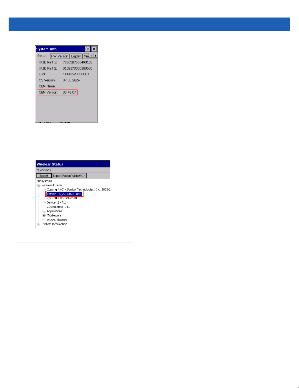
OEM Software
Use this procedure to determine the OEM software version on the MC18:
1. Click Start > Settings > Control Panel > System Info icon to view the OEM software version.
Page 14
xii MC18 Product Reference Guide
MC18
Fusion Software
Click Start > Programs > Fusion > Wireless status > Versions to determine the Fusion software version on
MC18.
Chapter Descriptions
Topics covered in this guide are as follows:
•
Chapter 1, Getting Started, describes the features and basic operation of the MC18, lists the accessories
for the MC18 and explains how to install and charge the batteries and start the MC18 for the first time.
•
Chapter 2, Staging and Provisioning, provides information for staging and provisioning the MC18.
•
Chapter 3, Wireless Applications, provides instructions for configuring the wireless adapter.
•
Chapter 4, Sync with Host Computer, provides instructions on installing a sync application and setting up
a partnership between the MC18 and a host computer.
•
Chapter 5, Using the Windows CE Desktop, provides instructions for connecting the MC18 to a host
computer and using the OS desktop of the MC18.
•
Chapter 6, Special Considerations, provides information to consider when using and developing
applications for the MC18.
•
Chapter 7, Pocket Browser, provides information on Sample Pocket Browser (mobile application
development tool) provided with the MC18.
Page 15

•
Chapter 8, Cradle Installation, provides installation instructions for the MC18 cradles and other
accessories.
•
Chapter 9, Application Deployment, provides instructions for downloading software and files to the
MC18.
•
Chapter 10, Maintenance and Troubleshooting, includes instructions on cleaning and storing the MC18,
and provides troubleshooting solutions for potential problems during MC18 operation.
•
Appendix A, Technical Specifications, includes a table listing the technical specifications for the MC18
and accessories.
•
Appendix B, App Launcher Configuration, provides information for configuring the App Launcher
application.
Notational Conventions
The following conventions are used in this document:
•
Italics are used to highlight the following:
• Chapters and sections in this guide
• Related documents
About This Guide xiii
•
Bold text is used to highlight the following:
• Dialog box, window and screen names
• Drop-down list and list box names
• Check box and radio button names
• Icons on a screen
• Key names on a keypad
• Button names on a screen
•
Bullets (•) indicate:
• Action items
• Lists of alternatives
• Lists of required steps that are not necessarily sequential
• Sequential lists (e.g., those that describe step-by-step procedures) appear as numbered lists.
NOTE This symbol indicates something of special interest or importance to the reader. Failure to read the note
will not result in physical harm to the reader, equipment or data.
CAUTION This symbol indicates that if this information is ignored, the possibility of data or material damage
may occur.
WARNING! This symbol indicates that if this information is ignored the possibility that serious personal
injury may occur.
Related Documents and Software
The following documents provide more information about the MC18 mobile computers.
Page 16

xiv MC18 Product Reference Guide
•
MC18 Quick Reference Guide, p/n MN000835A01
•
Microsoft Applications for Windows Mobile and CE 7.0 User Guide, p/n 72E-78456-xx
•
Enterprise Mobility Developer Kits, available at: http://www.zebra.com/support
•
Latest ActiveSync (Windows XP) or Windows Mobile Device Center (Windows 7) software, available at:
http://www.microsoft.com
For the latest version of this guide and all guides, go to: http://www.zebra.com/support
.
Service Information
If you have a problem with your equipment, contact Global Customer Support for your region. Contact
information is available at: http://www.zebra.com/support.
When contacting Global Customer Support, please have the following information available:
•
Serial number of the unit
•
Model number or product name
•
Software type and version number.
We respond to calls by E-mail, or telephone within the time limits set forth in support agreements.
If your problem cannot be solved by Global Customer Support, you may need to return your equipment for
servicing and will be given specific directions. Symbol Technologies is not responsible for any damages
incurred during shipment if the approved shipping container is not used. Shipping the units improperly can
possibly void the warranty.
If you purchased your business product from a business partner, contact that business partner for support.
Page 17

CHAPTER 1 GETTING STARTED
Introduction
This chapter describes the features of the MC18 and explains how to install and charge the battery, how to
capture data using the integrated Imager and how to reset the MC18.
Unpacking
Carefully remove all protective material from the MC18 and save the shipping container for later storage and
shipping.
Verify that box contains all the equipment listed below:
•
MC18
•
Two Torx screws inside a plastic bag (used for securing the battery cover to the MC18)
•
Quick Reference Guide
Inspect the equipment for damage. If you are missing any equipment or if you find any damaged equipment,
contact Support immediately. See Service Information on page xiv for contact information.
Removing the Screen Protection Film
A screen protection film is applied to the MC18 screen to protect the screen during shipping. To remove the
screen protector, carefully lift the thin film off the display.
Page 18

1 - 2 MC18 Product Reference Guide
Features
Status LED
Branding Plate Slot
Display
Scan Key
Figure 1-1
Front View
Page 19

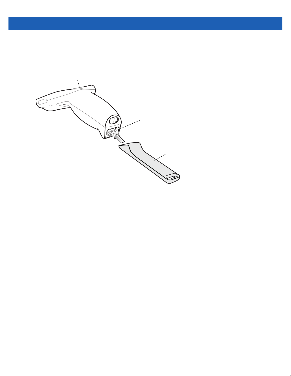
Scan Exit Window
Getting Started 1 - 3
Branding Plate Slot
Speaker
Figure 1-2
Battery Cover
Power Connector
Back View
Page 20

1 - 4 MC18 Product Reference Guide
Accessories
Table 1-1
MC18 Lithium Ion Battery BTRY-MC18-27MAG-01 MC18 Lithium Ion Battery.
High Density (HD) Three Slot
Cradle (Locking).
High Density (HD) Three Slot
Cradle (Non-Locking)
Super High Density (SHD) Three
Slot Cradle (Locking)
Accessories
Accessory Part Number Description
BTRY-MC18-27MAG-10 MC18 Lithium Ion Battery (
CRD-MC18-3SLCKH-01
CRD-MC18-3SLOTH-01
CRD-MC18-3SLCKS-01
The cradle is used for docking up to three
MC18 units in HD installation configuration.
The cradle slots are equipped with a
mechanism that locks the MC18 units inside
the slots.
The Three Slot Cradle requires
unit (
PWRS-14000-241R), DC line cord and
country specific AC line cord (sold
separately).
The cradle is used for docking up to three
MC18 units in HD installation configuration.
Requires
(
PWRS-14000-241R), DC line cord and
country specific AC line cord (sold
separately).
The cradle is used for docking up to three
MC18 units in SHD installation configuration.
The cradle slots are equipped with a
mechanism that locks the MC18 units inside
the slots. Requires power supply unit
(PWRS-14000-241R), DC line cord and
country specific AC line cord (sold separately).
power supply unit
QTY-10
power supply
).
Single Slot Cradle
Release Key KT-MC18-CKEY-20 Tool used to mechanically unlock the MC18
MC18 Terminal Reboot Tool KT-MC18-REBOOT-05 Tool used to perform cold boot of the MC18
Cradle Cover Removal Tool
Deployment Kit
CRD-MC18-1SLOT-01
KT-MC18-CTOOL-01 Tool used for removing the Three Slot Cradle
KT-MC18-CSTKIT-01 Includes:
The cradle is used for docking a single MC18.
Requires power supply unit
(PWRS-14000-241R), DC line cord and
country specific AC line cord (sold separately).
from the Three Slot Cradle and the Single
Slot Cradle (QTY-20).
(QTY-5).
cover.
•
20-pack of Release Key
(KT-MC18-CKEY-20)
•
5-pack of Terminal Reboot Tool
KT-MC18-REBOOT-05)
•
One Three Slot Cradle Front Panel
Removal Tool (KT-MC18-CTOOL-01)
Page 21

Getting Started 1 - 5
Table 1-1
Single Slot Cradle Release Key PSS-3KY01-00R
Cart Holder Mounting Kit PSS-3SH01-00R Kit
Programming Cable CBL-MC18-USB1-01
Interconnection Cable 25-66431-01R
Cradle Interconnection Extension
Cable
Charging Cable CBL-MC18-Y2MET-01 DC “Y” charging cable (
DC Charging Cable 25-66420-01R
Accessories (Continued)
Accessory Part Number Description
Key used to mechanically unlock the MC18
from a Single Slot Cradle (QTY-20)
for mounting the MC18 on a shopping cart.
USB communication cable for connecting the
MC18 to a host computer.
An extension cable (12.6 Inch / 32 centimeter)
for connecting the Three Slot Cradle to
charging cable that is connected to
supply unit (PWRS-14000-241R).
CBL-MC18-EXINT1-01
An Interconnection extension cable (12.6 Inch
/ 32 centimeter) for connecting Three Slot
Cradle.
centimeter) for connecting cradles to power
supply unit (PWRS-14000-241R).
DC charging cable (19.5 Inch / 49.5
centimeter) used to connect a power supply
unit (PWRS-14000-241R) to one Single Slot
Cradle.
.
DC “Y”
power
19.5 Inch / 49.5
DC “Y” Charging Cable Long 25-67592-01R
DC “Y” Charging Cable Short 25-66210-01R
Power Supply Unit
AC Line Cord
AC Line Cord
AC Line Cord
AC Line Cord
PWRS-14000-241R
23844-00-00R
50-16000-221R
50-16000-671R
50-16000-217R
DC “Y” charging cable (39.7 Inch / 1 meter).
Connects a power supply unit
(PWRS-14000-241R) to two separate Three
Slot Cradles.
DC “Y” charging cable (19.5 Inch / 1 meter).
Connects a power supply unit
(PWRS-14000-241R) to two separate Three
Slot Cradles.
100-240VAC, 12VDC, 9A. Requires country
specific AC line cord and DC cable (sold
separately).
AC Line Cord, 7.5 feet long, grounded, three
wire for power supplies. Associated Country:
United States
AC Line Cord, 1.8 meter, meter grounded,
three wire, USA NEMA 5-15P. Associated
Country: United States
AC Line Cord, 1.8 meter, grounded, three wire,
CIE 23-16 plug. Associated Country: Italy.
AC Line Cord, 1.9 meter, grounded, three wire,
AS 3112 plug. Associated Countries:
Australia, New Guinea
AC Line Cord
50-16000-218R
AC Line Cord, 1.8 meter, grounded, three wire,
NEMA 1-15P plug. Associated Country:
Japan.
Page 22

1 - 6 MC18 Product Reference Guide
Table 1-1
Accessory Part Number Description
AC Line Cord
AC Line Cord
AC Line Cord
AC Line Cord
AC Line Cord
AC Line Cord
Accessories (Continued)
50-16000-219R
50-16000-220R
50-16000-257R
50-16000-669R
50-16000-672R
50-16000-678R
AC Line Cord, 1.8 meter, grounded three wire,
BS1363 plug. Associated countries: Hong
Kong, Iraq, Malaysia, Singapore, United
Kingdom.
AC Line Cord, 1.8 meter, grounded three wire
CEE 7/7plug. Associated countries: Europe,
Abu Dhabi, Bolivia, Dubai, Egypt, Iran, Russia,
Vietnam.
AC Line Cord, 1.8 meter, grounded three wire,
IEC 60320 C13 plug. Associated Country:
China.
1.9 meter grounded three wire, BS 546 Plug.
Associated country: India.
1.9 meter grounded three wire, S132 Plug.
Associated country: Israel.
36 inch grounded three wire.
Associated country: United States
Page 23

Status LED
The Status LED indicates imaging status. Table 1-2 describes the Status LED indications.
Getting Started 1 - 7
Status LED
Figure 1-3
Table 1-2
Off
Red
Single Green blink
Scan Key
The Scan key operates the imager camera when a scanning application is active. When the MC18 is turned
off, pressing the Scan key to power on the MC18.
MC18 Status LED
Status LED Indications
LED State Indication
Normal operation or MC18 is turned off.
Imaging in progress (Scan key is pressed).
Successful decode.
NOTE The operation of the Scan key can be modified by programming or application to enable more or different
functionality. Refer to the EMDK Help file for detailed information for programming the Scan key.
Figure 1-4
Scan Key
Scan Key
Page 24
1 - 8 MC18 Product Reference Guide
Getting Started
To start using the MC18 for the first time:
•
Install the battery
•
Charge the battery.
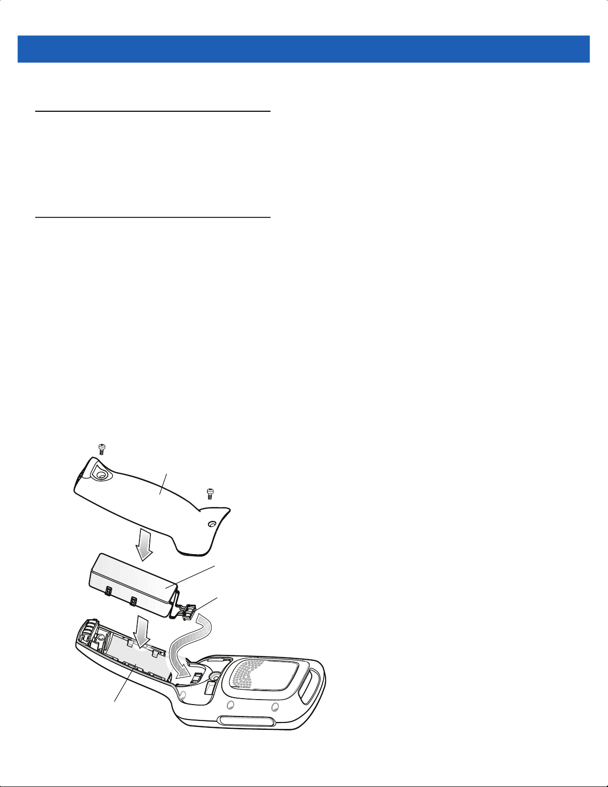
Installing the Battery
To install the battery:
1. Remove tape securing battery cover to handle.
2. Lift the battery cover from the handle.
3. Guide and press the battery cable connector into the female connector inside the battery compartment.
The connector is designed to only fit one way.
4. Place the battery inside the battery compartment.
5. Place the battery cover onto the handle.
6. Remove the two Torx screws from the provided plastic bag, inside the shipping box.
7. Secure the battery cover with the two Torx screws using a T8 Torx drive. Torque the screws to 3.6 Kgf-cm
(3.1 in-lb).
Battery Cover
Battery
Battery Cable Connector
Battery
Compartment
Figure 1-5
Installing the Battery
Page 25

Getting Started 1 - 9
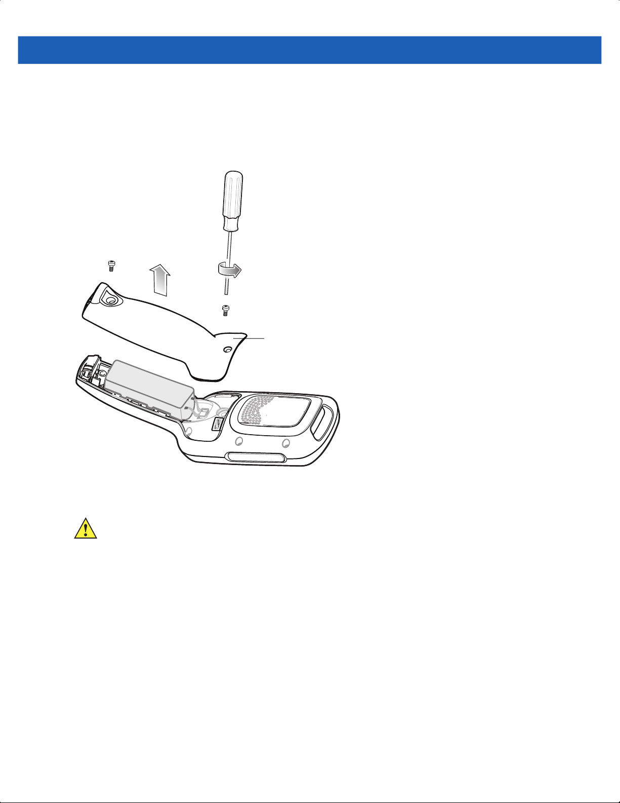
Removing the Battery
To remove the battery:
1. Suspend the MC18 by tapping Start > Suspend.
CAUTION The MC18 must be suspended before removing the battery. Failing to suspend the MC18 before
removing the battery may damage the data stored on flash memory or corrupt the operating system files.
2. Use T8 Torx drive to remove the two screws that secure the battery cover.
3. Lift the battery cover from the handle.
4. Inside the battery compartment, press down the plastic tab of the Battery cable connector and slide it out of
the female connector.
5. Remove the battery from the battery compartment.
Battery Cover
Press down plastic tab to release
Battery
Battery Compartment
Figure 1-6
Removing the Battery
Charging the Battery
CAUTION Ensure that you follow the guidelines for battery safety described in Battery Safety Guidelines on page
10-1.
Battery Cable Connector
Before using the MC18 for the first time, charge the battery. The battery fully charges in approximately four
hours.
To charge the battery:
1. Ensure the cradle is connected to the appropriate power source. See Chapter 8, Cradle Installation for
more information.
Page 26

1 - 10 MC18 Product Reference Guide
2. Dock the MC18 in a cradle. The MC18 starts to charge automatically and is shown on the taskbar if
the Windows CE desktop is visible.
Figure 1-7
Three Slot CradleSingle Slot Cradle
Docking MC18 into Cradle
Page 27

Starting the MC18
The MC18 starts automatically as soon as power is applied; either with a charged battery installed or when
inserted into the cradle.
If charged battery is installed and the MC18 is turned off, press and hold the Scan key for five seconds to turn
on.
When the MC18 is powered on for the first time, it initializes its system. The splash screen appears for a short
period of time.
Getting Started 1 - 11
Figure 1-8
On the MC18, the splash screen is followed by the App Launcher window.
Splash Screen
NOTE App Launcher window may vary depending upon the MC18 operating system version.
Figure 1-9
App Launcher Window
Page 28

1 - 12 MC18 Product Reference Guide
Powering On
To power on the MC18, press and release the Scan key.
Data Capturing
The MC18 imager allows collection of data by scanning bar codes.
The imager has the following features:
•
Reads a variety of bar code symbologies, including the most popular linear, postal, and 2-D code types
(see Appendix A, Technical Specifications).
•
Contains advanced intuitive aiming light for easy point-and-shoot operation.
Scanning Considerations
Typically, scanning is a simple matter of aim, scan/decode and a few quick trial efforts master it. However, two
important considerations can be used to optimize any scanning performance:
•
Range
Any scanning device decodes well over a particular working range — minimum and maximum distances
from the bar code. This range varies according to bar code density and scanning device optics.
Scanning within range brings quick and constant decodes; scanning too close or too far away prevents
decodes. Move the MC18 closer and further away to find the right working range for the bar codes being
scanned. However, the situation is complicated by the availability of various integrated scanning modules.
The best way to specify the appropriate working range per bar code density is through a chart called a
decode zone for each scan module. A decode zone simply plots working range as a function of minimum
element widths of bar code symbols.
•
Angle
Don’t scan at too sharp an angle; the scanner needs to collect scattered reflections from the scan to make
a successful decode. Practice quickly shows what tolerances to work within.
NOTE Contact the Global Customer Support if chronic scanning difficulties develop. Decoding of properly printed
bar codes should be quick and effortless.
Scanning Bar Codes
1. Open any application that can receive text or go to Windows CE desktop.
2. Aim the scan exit window at the bar code.
3. Press the Scan key - the status LED illuminates red.
Ensure the red aiming dot is at the center of the bar code. Upon successful decode, the Status LED
changes from red to green and audible beep sounds if bar code was decoded successfully.
Page 29

Getting Started 1 - 13
Red Aiming Dot
Correct
Figure 1-10
4. Release the Scan key. The bar code data displays on the screen.
Imager Illumination Frame
Incorrect
Red Illumination Frame
Figure 1-11
Scanning Sample Application Screen
Scanning Tips
Optimal scanning distance varies with bar code density and scanner optics.
•
Hold the scanner farther away for larger symbols.
•
Move the scanner closer for symbols with bars that are close together.
NOTE Scanning procedures depend on the application and MC18 configuration. An application may use
different scanning procedures from the one listed above.
DataWedge
DataWedge is an application that reads data from a scanning source, processes the data and sends the data
to an application as if the user is entering it on a keyboard. By default, DataWedge is enabled.
Enable the DataWedge Application
To enable the DataWedge Application:
1. Select Start > Settings > Control Panel > DataWedge icon.
Page 30

1 - 14 MC18 Product Reference Guide
2. Select Basic Configuration.
3. Select 1. Scanner input.
4. Select MegaPixel Imager:
5. Select 1. Enabled.
6. Click 0. Back.
7. Click 0. Back.
8. Click 0. Exit.
9. Click OK
Figure 1-12
10. Select Running to start the DataWedge process. The DataWedge Status changes to Ready.
Figure 1-13
11. Click OK to exit.
DataWedge Stopped
DataWedge Running
Disable DataWedge
To disable DataWedge:
1. Select Start > Settings > Control Panel > DataWedge icon.
2. Select the Running option to end the DataWedge process. The DataWedge Status changes to Stopped.
3. Select OK.
Page 31

Using DataWedge to Read Bar Codes
To read bar codes with DataWedge:
1. Enable DataWedge.
2. Open an application and select a text box or field for entering the bar code data.
3. Use one of the optional scanners and capture the bar code data. The data appears in the text box.
Manual Release of MC18 from Cradles
The MC18 cradles contain a locking mechanism that locks the MC18 inside the cradle when docked. The
MC18 releases from the cradle when a software command is received from the system. If the MC18 fails to
un-lock during normal operation, use a release key to un-lock the MC18.
Manual Release of MC18 from the Single Slot Cradle
NOTE The MC18 also can be unlock from the cradle by software command using the PocketBrowser application
(see Sample Application on page 7-1) or by the Cradle Utility (see Setting and Controlling the Cradle on
page 6-5).
Getting Started 1 - 15
To release a locked MC18 from a Single Slot Cradle:
1. Insert the release key into the slot located at the bottom side of the cradle.
2. While pressing the release key all the way into the slot, remove the MC18 from the cradle.
Release Key
Figure 1-14
Manual Release of MC18 from a Single Slot Cradle
Manual Release of MC18 from the Three Slot Cradle
NOTE The cradle includes models that do not have a locking mechanism. To identify the model of cradle, refer to
Table 1-1 on page 1-4.
NOTE The MC18 also can be released by software command using the Cradle Utility application (see Setting
and Controlling the Cradle on page 6-5).
To release a locked MC18 from a Three Slot Cradle:
1. Insert the release key straight into the slot, to a point where the bend stops.
Page 32

1 - 16 MC18 Product Reference Guide
2. Hold the release key pressed inside the slot and remove the MC18 from the slot.
Release Key
Figure 1-15
Manual Release of MC18 from a Three Slot Cradle
Page 33
Resetting the MC18
There are two types of resets, warm boot and cold boot. A warm boot restarts the MC18 by closing all running
programs.
A cold boot also restarts the MC18, but erases all stored records and entries in RAM. In addition it returns
formats, preferences and other settings to the factory default settings which are not saved in flash memory
(Application and Platform folders).
Perform a warm boot first. This restarts the MC18 and saves all stored records and entries. If the MC18 still
does not respond, perform a cold boot.
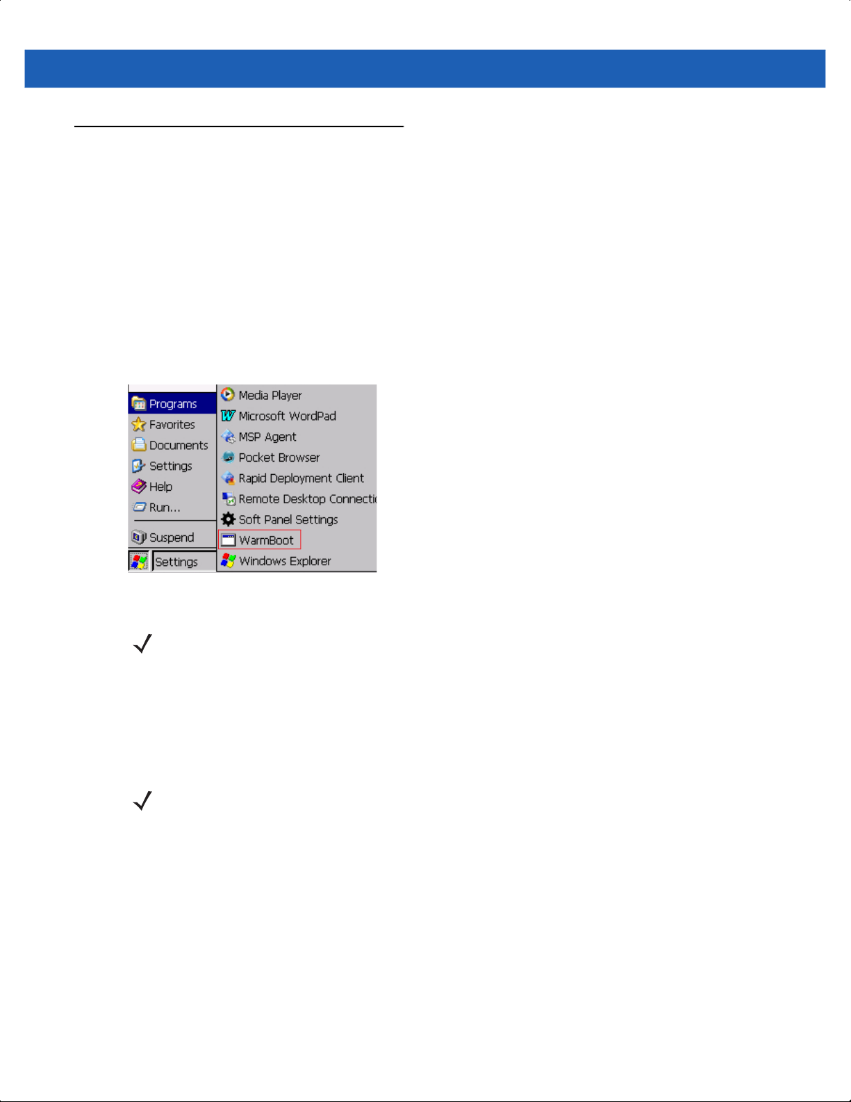
Performing a Warm Boot
To perform a warm boot tap Start > Programs > WarmBoot.
Getting Started 1 - 17
Figure 1-16
Performing a Warm Boot
NOTE Warm boot shortcuts are also available in App Launcher application screen (see App Launcher Screen
on page 5-1).
Performing a Cold Boot
A cold boot restarts the MC18 and erases all user stored records and entries that are not saved in flash
memory (Application and Platform folders). Never perform a cold boot unless a warm boot does not solve the
problem.
NOTE Any data previously synchronized with a computer can be restored during the next ActiveSync operation.
Performing Cold Boot when the MC18 is Docked Inside the Cradle
To perform a cold boot when the MC18 is docked inside the cradle:
1. Press and hold the Scan key for 10 seconds until the display powers off.
2. Briefly press and release the Scan key, the MC18 reboots.
Performing Cold Boot when MC18 is Out of the Cradle
To perform a cold boot when the MC18 is out of the cradle:
1. Insert the terminal reboot tool into the MC18 power connector.
Page 34
1 - 18 MC18 Product Reference Guide
2. Press and hold the Scan key for 10 seconds until the display powers off.
3. Remove the terminal reboot tool.
4. Briefly press and release the Scan key - the MC18 reboots.
Scan Key
Power Connector
Terminal Reboot Tool
Figure 1-17
Terminal Reboot Tool
Page 35

CHAPTER 2 STAGING AND
PROVISIONING
Introduction
To stage and provision an MC18 device, use one of the following pre-installed Mobile Device Management
(MDM) clients:
•
MobiControl Stage
•
Rapid Deployment Client
•
MSP Agent
For more information about staging and licensing, contact AirWatch, SOTI or your preferred MDM provider.
NOTE MSP is End Of Sale. The MSP agent is preloaded on Zebra devices but requires an AirWatch license.
Page 36

2 - 2 MC18 Product Reference Guide
Page 37

CHAPTER 3 WIRELESS
APPLICATIONS
Introduction
Wireless Local Area Networks (WLANs) allow the MC18 mobile computers to communicate wirelessly and
send captured data to a host device in real time. The MC18 supports the 802.11a, 802.11b, 802.11g and
802.11n standards. Before using the MC18 on a WLAN, the facility must be set up with the required hardware
to run the wireless LAN and the MC18 must be configured. Refer to the documentation provided with the
access points (APs) for instructions on setting up the hardware.
To configure the radio in the MC18, use the Fusion APIs in the Enterprise Mobility Developer’s Kit (EMDK).
Refer to the EMDK Help file for detailed information.
The MC18 contain the Wireless Applications to allow configuration of the WLAN radio. On the MC18, access
the Wireless applications by tapping the on the taskbar.
Wireless Application on the MC18
To configure the MC18, a set of wireless applications provide the user with the tools to configure and test the
wireless radio embedded in the MC18. The following wireless applications are available on the task tray from
Wireless Application menu:
the
•
Wireless Status
•
Wireless Diagnostics
•
Find WLANs
•
Manage Profiles
•
Options
•
Log On/Off
•
Enable/Disable Radio.
Page 38

3 - 2 MC18 Product Reference Guide
Refer to the Wireless Fusion Enterprise Mobility Suite User Guide for Version X.XX, for information on
configuring wireless profiles, where X.XX indicates the Fusion version. To determine the Fusion version see
Fusion Software on page xii.
NOTE The Windows CE 7.0 desktop may not be visible because the App Launcher application screen displays.
To view the desktop, close all running applications.
By default, the task tray displays below the screen. If the taskbar is set to be hidden, display the task tray by
placing your finger over the portion of the task tray that is visible (a thin gray line at the bottom of the screen).
The task tray automatically appears.
tap the
Figure 3-1
Signal Strength icon to display the Wireless Application menu.
Signal Strength Icon
Wireless Applications Menu
Signal Strength Icon
The Signal Strength icon in the task tray indicates the MC18 wireless signal strength as follows:
Table 3-1
Icon Status Action
Wireless Applications Icons, Signal Strength Descriptions
Excellent signal strength Wireless LAN network is ready to use.
Very good signal strength Wireless LAN network is ready to use.
Good signal strength Wireless LAN network is ready to use.
Page 39

Wireless Applications 3 - 3
Table 3-1
Icon Status Action
Wireless Applications Icons, Signal Strength Descriptions (Continued)
Fair signal strength Wireless LAN network is ready to use. Notify the network
administrator that the signal strength is only “Fair”.
Poor signal strength Wireless LAN network is ready to use. Performance may not
be optimum. Notify the network administrator that the signal
strength is “Poor”.
Out-of-network range (not
associated)
No wireless LAN network connection. Notify the network
administrator.
Page 40
3 - 4 MC18 Product Reference Guide
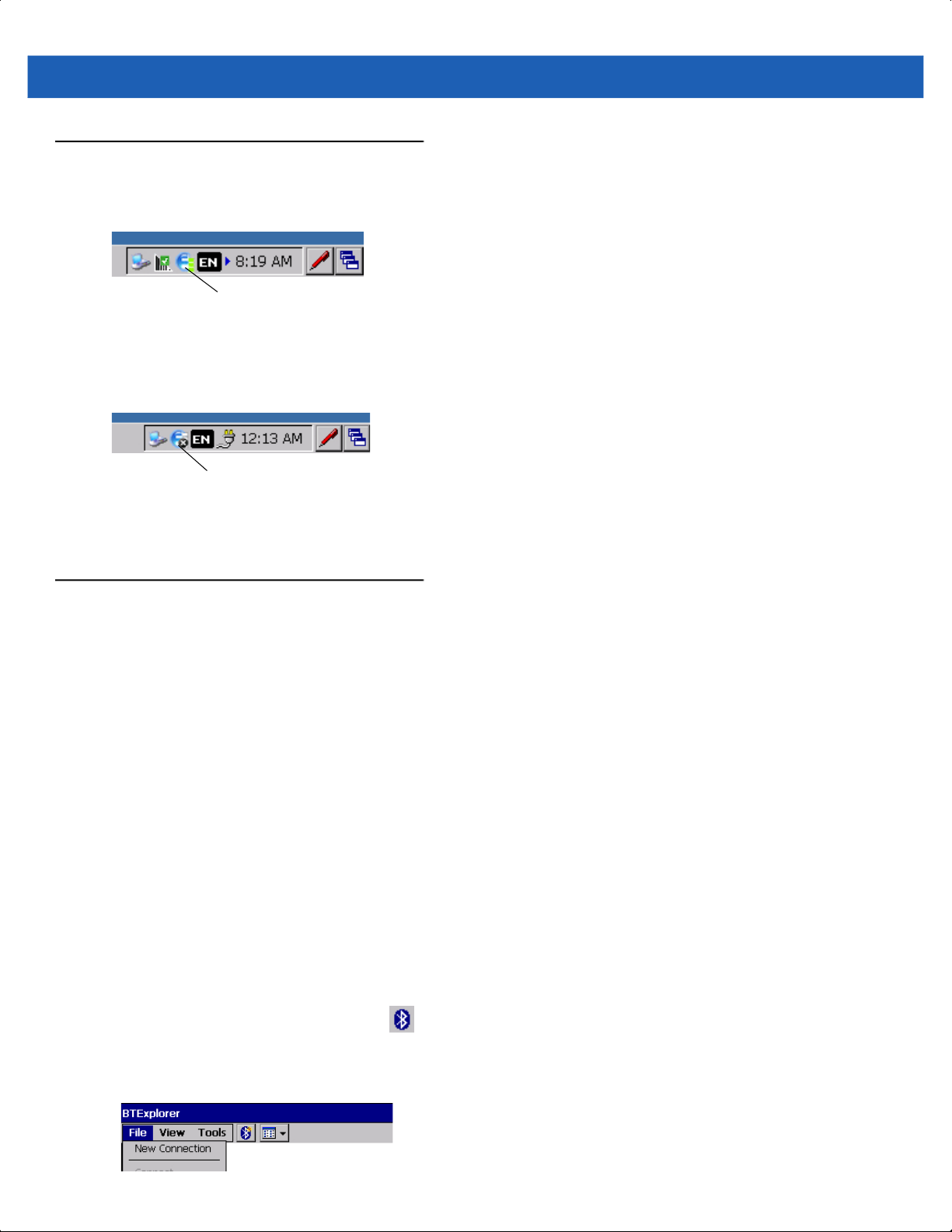
Turning Off the Radio
To turn off the WLAN radio tap the Wireless Connection Status icon on the task tray and select Disable Radio.
Wireless Connection Status Icon
Figure 3-2
A red i appears at the bottom of the icon indicating that the radio is disabled (off).
To turn the radio back on, tap the
Figure 3-3
The red X disappears from the icon indicating that the radio is enabled (on).
Bluetooth
MC18 is a dual mode device that support Bluetooth Low Energy (BLE) in addition to the regular Bluetooth
BR/EDR. The BLE that is a light-weight subset of classic Bluetooth is identical to a regular Bluetooth but with a
completely different lineage.
MC18 uses Stonestreet Bluetooth exposes GATT (Generic Attribute) API's. Through these API's BT 4.0
compliant profiles or Indoor location applications can be implemented. For for API documentation, refer to
Enterprise Mobility Developer Kit (EMDK) Help.
Wireless Connection Status Icon - Radio On
Wireless Connection Status icon on the task tray and select Enable Radio.
Wireless Connection Status Icon
Wireless Connection Status Icon - Radio On
The MC18 supports the following Bluetooth profiles:
•
Generic Access Profile - GAP
•
Service Discovery Access Profile - SDAP
•
Serial Port Profile – SPP
•
Wake on Bluetooth
Bluetooth Printing
Use this procedure to pair the MC18 to a Bluetooth printer:
1. Launch BT Explorer by tapping the icon in notification area.
2. Click Show BTExplorer.
3. Click File > New Connection.
Page 41

Wireless Applications 3 - 5
4. Click Next on New Connection Wizard screen to start device discovery to start the discovery process.
5. Select the printer and choose next to start pairing process.
6. Enter the PIN. Once the printer is paired with MC18, services of printer are listed.
7. Choose serial printer service and connect.
8. Select the port MC18 to connect to printer.
Page 42

3 - 6 MC18 Product Reference Guide
Page 43

CHAPTER 4 SYNC WITH HOST
COMPUTER
To communicate with a host computer, the host computer requires a synchronization program. After
synchronizing the MC18 with a host computer, changes made on the MC18 or host computer appear in both
places.
To communicate with a host computer running Windows XP, install Microsoft ActiveSync (version 4.5 or
higher).
To communicate with a host computer running Windows 7, install Windows Mobile Device Center (WMDC
version 6.1 or higher).
Using a synchronization software:
•
Allows working with MC18-compatible host applications on the host computer. The synchronization
software replicates data from the MC18 so the host application can view, enter, and modify data on the
MC18.
•
Synchronizes files between the MC18 and host computer, converting the files to the correct format.
•
Backs up the data stored on the MC18. Synchronization is a one-step procedure that ensures the data is
always safe and up-to-date.
•
Copies (rather than synchronizes) files between the MC18 and host computer.
•
Controls when synchronization occurs by selecting a synchronization mode, e.g., set to synchronize
continually while the MC18 is connected to the host computer, or set to only synchronize on command.
•
Selects the types of information to synchronize and controls how much data is synchronized.
Installing the Synchronization Software
To install ActiveSync or Windows Mobile Device Center software on the host computer, logon to Microsoft web
site at http://www.microsoft.com. Refer to the installation instructions included with the software.
Connecting the MC18 to a Host Computer
Perform this procedure to connect the MC18 to a host computer:
Page 44
4 - 2 MC18 Product Reference Guide
1. Ensure that synchronization program (ActiveSync for Windows XP or Windows Mobile Device Center for
Windows 7) is installed properly on the host computer.
2. Using a T8 Torx drive, remove the two Torx screws securing the battery cover to the back housing of the
MC18 (see Figure 4-1).
Battery Cover
Figure 4-1
3. Align the connector on the programming cable panel with the sync connector on the MC18 and lower the
Remove Battery Cover
CAUTION Do not remove the battery cover while the MC18 is on and do not operate the MC18 with the battery
cover removed. Follow proper Electro-Static Discharge (ESD) precautions to avoid damaging the
MC18. Proper ESD precautions include, but are not limited to, working on an ESD mat and ensuring
that the operator is properly grounded.
panel to fit on the MC18.
4. Hand-tighten the two T8 Torx screws securing the programming cable panel to the MC18.
Page 45
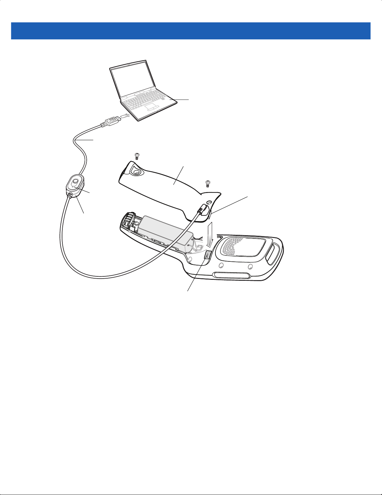
Programming Cable
Sync with Host Computer 4 - 3
Host Computer
Programming Cable Panel
Dot
Switch
Sync Connector
Figure 4-2
5. Slide the programming cable switch to the side marked with a dot (see Figure 4-2).
6. Connect the USB connector of the programming cable panel to the host computer. The host computer
Installing the Programming Cable
Connector
automatically detects the MC18 and starts ActiveSync or Windows Mobile Device Center - the
synchronization program window appears on the host computer screen.
Page 46

4 - 4 MC18 Product Reference Guide
ActiveSync
Figure 4-3
7. For ActiveSync, select the Yes radio button to create a partnership with the host computer or No radio
Synchronization Program Windows
Windows Mobile Device Center
button to connect as a guest.
For Mobile Device Center, select Set up your device or select Connect without setting your device to
connect as a guest.
8. For ActiveSync, click Next. The Microsoft ActiveSync window indicates that it is connected to the MC18.
For Windows Mobile Device Center, select the required option.
Figure 4-4
Windows Mobile Device CenterActiveSync
ActiveSync / Windows Mobile Device Center Connected Window
Page 47

Sync with Host Computer 4 - 5
Removing the Programming Cable Panel
Perform this procedure to remove the programming cable panel.
CAUTION Follow proper Electro-Static Discharge (ESD) precautions to avoid damaging the MC18. Proper ESD
precautions include, but are not limited to, working on an ESD mat and ensuring that the operator is
properly grounded.
1. Using a T8 Torx drive, loosen the two screws securing the programming cable panel to the MC18.
2. Lift the programming cable panel straight up.
Installing the Battery Cover
1. Align the battery cover on the MC18 and lower the panel to fit on the MC18.
2. Using a T8 Torx drive, secure with battery cover to the MC18 using the two Torx screws. Torque the screws
to 3.6 kgf/cm (3.1 in-lbs).
Setting Up an ActiveSync Connection on the Host Computer (with Windows XP)
NOTE The normal function of the product may be disturbed by Strong Electro Magnetic Interference (for example,
static electricity). If so, simply remove and re-insert the MC18 to resume normal operation. In case the
function does not resume, please use the product in another location.
Use this procedure to start ActiveSync:
1. Select Start > Programs > Microsoft ActiveSync on the host computer. The ActiveSync window displays.
Figure 4-5
2. In the ActiveSync window, select File > Connection Settings. The Connection Settings window appears.
ActiveSync Window
NOTE Assign each MC18 a unique device name. Do not try to synchronize more than one MC18 to the same
name.
Page 48

4 - 6 MC18 Product Reference Guide
Figure 4-6
3. Select Allow USB connections check box.
4. Select the Show status icon in Taskbar check box.
5. Select OK to save any changes made.
Connection Settings Window
Setting up a Partnership
Use this procedure to set up a partnership:
1. If the Get Connected window does not appear on the host computer, select Start > All Programs > Microsoft
ActiveSync.
Figure 4-7
2. Select if you want to set up a partnership. Select either the Yes or No radio button.
3. Click Next.
4. If No is selected, skip to step 7.
New Partnership Window
Page 49

Sync with Host Computer 4 - 7
Figure 4-8
5. Select the appropriate settings and click Next.
Figure 4-9
6. Click Finish.
7. The Microsoft ActiveSync window displays.
Select Synchronization Setting Window
Setup Complete Window
Page 50

4 - 8 MC18 Product Reference Guide
Figure 4-10
During the first synchronization, information stored on the MC18 is copied to the host computer. When the copy
is complete and all data is synchronized, the MC18 can be disconnected from the host computer.
For more information about using ActiveSync, start ActiveSync on the host computer, then see ActiveSync
Help.
ActiveSync Connected Window
NOTE The first ActiveSync operation must be performed with a local, direct connection. To retain partnerships
after a cold boot, capture partnership registry information in a .reg file and save it in the Flash File
System, See the detailed information provided in the EMDK Windows CE Help File for Mobile
Computers.
Setting Up a Windows Mobile Device Center Connection on the Host Computer (with Windows 7)
To set up a Sync connection using Windows 7:
1. Select Start > All Programs > Windows Mobile Device Center on the host computer.
Figure 4-11
Windows Mobile Device Center (WMDC) Window
Page 51

Sync with Host Computer 4 - 9
2. In the WMDC window, under Mobile Device Settings, click Connection settings.
Figure 4-12
3. Select Allow USB connections and adjust any additional settings as needed.
4. Click OK to save your settings.
Connection Settings Window
Setting up a Partnership
To set up a partnership:
1. In the WMDC window, under Mobile Device Settings, click Set up your device.
2. Check the Files check box and click Next.
Figure 4-13
Select Synchronization Setting Window
Page 52
4 - 10 MC18 Product Reference Guide
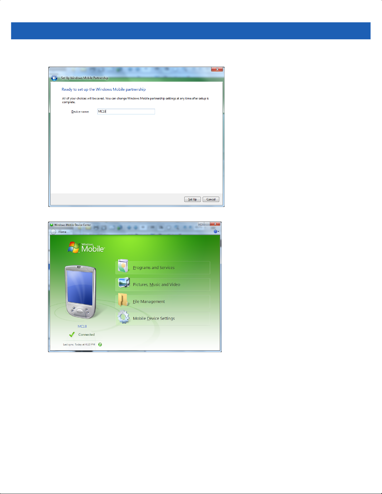
3. Set your device name and click Set Up - the Connected Window will display.
Figure 4-14
Figure 4-15
Setup Complete Window
Connected Window
During the first synchronization, information stored on the MC18 is copied to the host computer. When the copy
is complete and all data is synchronized, the MC18 can be disconnect from the host computer.
For more information about using WMDC, start the application on the host computer, then see Help.
Page 53

CHAPTER 5 USING THE WINDOWS
CE DESKTOP
Introduction
The MC18 runs Windows CE 7.0 operating system and the operating system is only available for configuration
when connected to a host computer via sync program.
The MC18 enabled device is available using the user interface (UI).
App Launcher Screen
The App Launcher screen allows the user to launch specific applications by tapping on a menu an item. If the
App Launcher screen is closed, launch the App Launcher screen by tapping the App Launcher shortcut on
the MC18 desktop or selecting AppLauncher in the Start > Programs > Windows Explorer directory.
See Appendix B, App Launcher Configuration for instructions on modifying the App Launcher menu.
NOTE App Launcher screen may vary depending upon the operating system version.
Page 54

5 - 2 MC18 Product Reference Guide
Figure 5-1
Table 5-1
Rapid Deployment Client Enables to launch the Rapid Deployment application.
File Explorer Enables working with files, folders and network on the MC18.
System Information Displays information about the system software versions.
Utilities Enables easy access to most used applications such as Internet Explorer.
Cradle Applications Enables software update, control, settings and diagnostics of the cradle.
Demo Applications Enables to Demonstrate the operation of the MC18 such as scan
Test Applications Enables diagnostics and testing of the MC18.
Warm Boot Enables to perform warm boot to the MC18.
About Displays information about the App Launcher.
Exit Enables to Close the App Launcher screen.
App Launcher Screen
App Launcher Screen - Item Descriptions
Item Description
application.
Page 55

Windows CE 7.0 Desktop
NOTE The Windows CE 7.0 desktop may not be visible because the App Launcher application is active. To view
the desktop, close all running applications.
The following paragraphs describe the Windows CE 7.0 desktop. Depending upon the customer’s
configuration of the MC18, the desktop may not be available.
Status Icons
The Taskbar at the bottom of the window displays the active programs, battery status and communication
status. The taskbar (at the bottom of the screen) displays the Start button, active programs, battery status and
communication status. The taskbar icons are described in Table 5-2. The taskbar icons display the function
status, indicate what programs are active and indicate the battery charge status. The Taskbar buttons are used
to access menus, select/deselect functions or to change display windows.
•
Active Programs Icons: The active applications icons are displayed on the taskbar. If more than one
program is active, icons can be used to toggle between the open programs (applications). Tap on a
taskbar application to maximize the application.
Using the Windows CE Desktop 5 - 3
•
AC Power/Battery Status Icons: The AC Power/Battery Status icons are shown in the taskbar to indicate
the present power supply status of the MC18. The battery status icons provide the battery status in 10%
increments from 10% to 100%.
The Taskbar is shown on the lower part of the MC18 screen. To set the properties of the taskbar, see
Properties on page 5-6.
Taskbar
Status Icons
Figure 5-2
Start Button
Taskbar
Page 56
5 - 4 MC18 Product Reference Guide
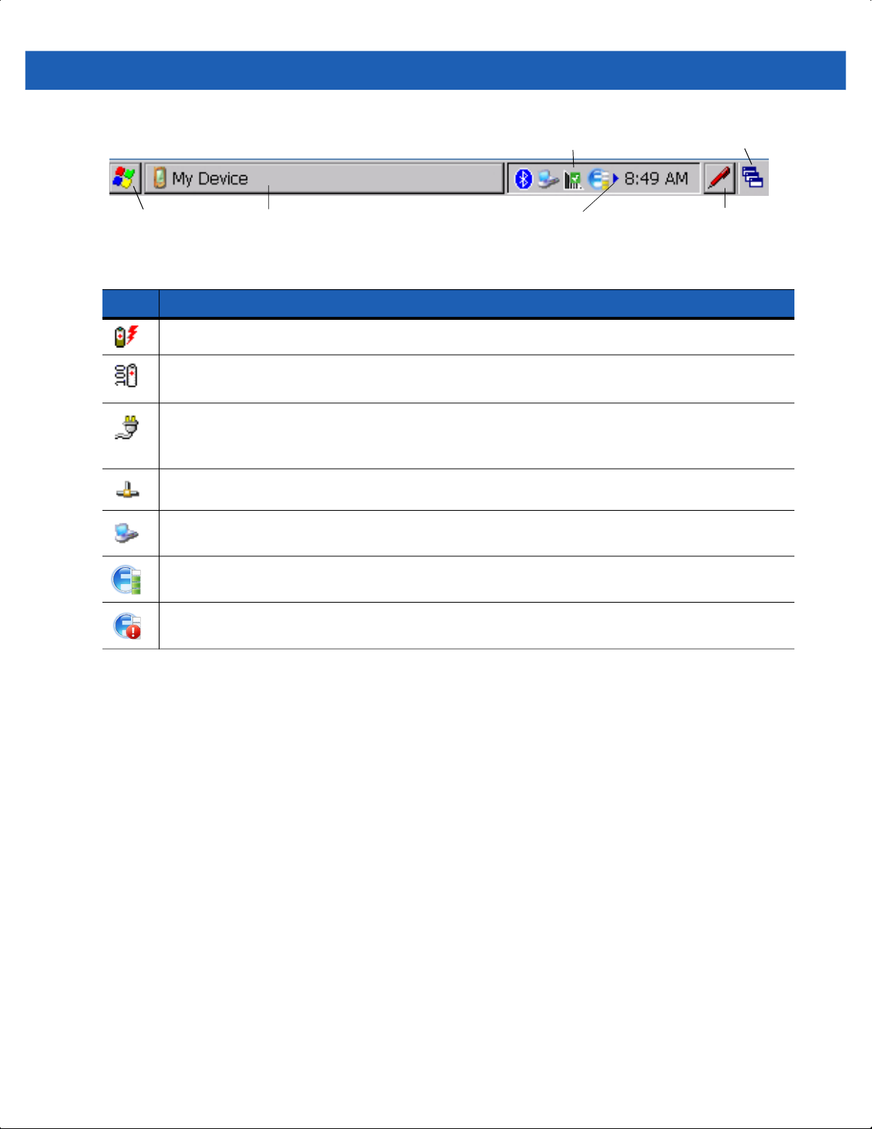
Task Bar with Status Icons
Start Button
Figure 5-3
Table 5-2
Icon Description
Taskbar
Taskbar Icons
Indicates that the battery is charging.
Indicates that the battery is fully charged (100% charged).
The battery status icons provide the battery status in 10% increments from 10% to 100%.
Indicates that the MC18 is locked inside a cradle, its battery is fully charged and operates on power
received from the cradle.
This icon may also be displayed if the MC18 is docked and unlocked inside the cradle.
Indicates IP status. Only displays when the MC18 is in emulation mode.
Indicates that the Sync application is running.
Currently Open Programs
Scroll Status Icons
Desktop Display Button
Keyboard Input Panel Button
Indicates that the wireless application radio is connected to a wireless LAN network with excellent
signal strength.
Indicates that the wireless application radio is not connected to a wireless LAN network.
Start Button
Tap the Start button to launch the Start menu.
•
Programs: Use to access available programs.
•
Favorites: Displays files in Favorites directory.
•
Documents: Displays files in Documents directory.
•
Settings: Accesses the Control Panel, the Network and Dial-up Connections and the Taskbar and Start
menu.
•
Help: Accesses the Windows CE Help.
•
Run . . . : Runs a program or application.
•
Suspend: Places the MC18 in the suspend state.
Page 57
Using the Windows CE Desktop 5 - 5
Figure 5-4
Start Menu
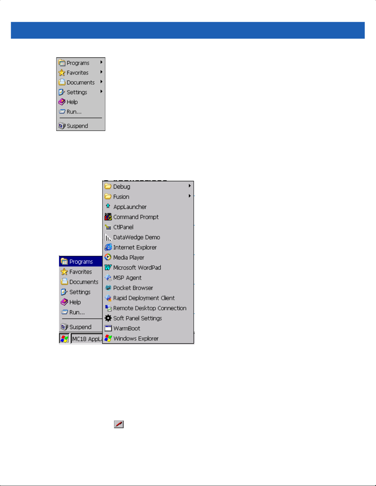
Programs Menu
From the Start menu, tap Programs to launch the Programs menu.
Figure 5-5
Programs Menu
Desktop Display Button
Use the Desktop Display button to minimize all open programs and display the desktop.
Entering Information Using the Keyboard Input Panels
Use the keyboard input panels (soft keyboard) to enter information in any program. To launch the keyboard
input panel, click the button on the taskbar. Select the type of input panel (Keyboard or XAMLIM). Tap a
key to enter the value. Tap the keyboard input panel button to display or to hide the keyboard input panel.
Page 58

5 - 6 MC18 Product Reference Guide
Keyboard
XAMLIM
Figure 5-6
Keyboard Input Panel
Task Bar and Start Menu Properties
Use the Properties functions to set display and clock options.
Properties
1. Tap Start > Settings > Taskbar and Start Menu ... . The Taskbar and Start Menu window displays.
Figure 5-7
2. This window provides taskbar options:
Taskbar and Start Menu- General Tab
•
Check the Always on Top check box to keep the taskbar on top of all other windows.
•
Check the AutoHide check box to make the taskbar disappear, click the bottom of the display to make
the taskbar return.
•
Check the Show Clock check box to display the clock on the taskbar.
3. Tap OK to save the settings and exit the window.
Advanced Tab
1. Tap the Advanced tab.
Page 59

Using the Windows CE Desktop 5 - 7
2. Tap the Clear button to delete all of the documents listed in the Start > Documents entry, see Start Button
on page 5-4. Typically this list is empty, but if there were documents in the list the Clear button would
delete them.
3. Tap the Expand Control Panel check box to display the entire contents of the Control Panel in list form,
rather than icons.
Figure 5-8
4. Tap OK to save the settings and exit the window.
Taskbar and Start Menu-Advanced Tab
Waking the MC18
The wake up conditions define what actions wake up the MC18 after it has gone into suspend mode. The
MC18 can go into suspend mode automatically by control panel time-out settings. These settings are
configurable and the factory default settings are shown in Table 5-3. To set the wake up conditions select Start
> Settings > Control Panel > Power icon > Wakeup tab.
Table 5-3
Touch Panel (Screen) No
Trigger 1 (Scan key) Yes
USB Cable Yes
Wakeup Default Settings
Condition for Wakeup Automatic Time-out
Figure 5-9
Wakeup Tab
Page 60

5 - 8 MC18 Product Reference Guide
Page 61

CHAPTER 6 SPECIAL
CONSIDERATIONS
Introduction
The chapter provides information for:
•
Using language fonts
•
Software development considerations
•
Improving battery charge time
•
Improving battery life
•
Cradle applications
•
MC18 Hardware Diagnostics
Fonts
The MC18 supports the following language fonts:
•
English
•
French
•
Italian
•
German
•
Spanish
•
Swedish
•
Russian
•
Greek (fonts support only)
•
Arabic (fonts support only)
The MC18 supports the installation of font libraries for use with application and web development. Simplified
Chinese, Korean, and Japanese font libraries are available on the Support Central Web site,
http://www.zebra.com/support. Other standard UTF-8 encoded fonts are available from third party font
Page 62

6 - 2 MC18 Product Reference Guide
vendors. Developers should refer to Microsoft and third party vendor documentation for development and
usage details.
It should be noted that installing a language font library will not change the language configuration of the
operating system image, i.e., Windows messages will still be displayed in the language designated in the
factory supplied operating system image.
Page 63

Special Considerations 6 - 3
Asian Font Installation
The Asian fonts must be installed onto the MC18.
Use this procedure to install Asian fonts onto the MC18.
1. Download the font package from Support Central.
2. Copy the language font files into the Application folder on the MC18:
•
.ttf, .ttc or .ac3 files
•
.reg files (required for Asian fonts)
•
.cpy files.
3. Cold boot the MC18.
After the MC18 reboots, the installed fonts are available for use.
Refer to http://msdn2.microsoft.com/en-us/library/aa911446.aspx for an explanation of font usage and
installation.
Software Development Considerations
•
Dim or turn off the backlight when the MC18 is idle.
•
Whenever possible use default key code settings.
•
To improve performance, use RAM instead of flash memory.
•
Always lock the cradle after unlocking it.
•
Cold booting the MC18 erases all files in RAM. Be sure to save any critical files in Application folder, e.g.;
Radio profile, time zone setting, license keys etc.
•
User developed applications should provide a method for exiting or launching Rapid Deployment to
enable re-staging the MC18.
•
For detailed information on how to control the cradle LEDs and locking/unlocking the MC18 in the cradle,
refer to the EMDK Help file.
Tips for Improving Battery Life
The MC18 has many functions to allow server/client applications control over its power management. To
improve battery life:
•
Place the MC18 in a cradle connected to AC power when not in use.
NOTE In suspend mode, the radio cannot communicate with an AP.
•
After the customer check-out, place the MC18 in suspend mode. This prevents the MC18’s battery from
discharging while sitting at a counter before being returned to the cradle. Once inserted in the cradle, the
MC18 wakes up automatically.
•
If placed in suspend mode, Scan key press can be set to wake up the MC18. This can greatly increase
battery life.
Page 64

6 - 4 MC18 Product Reference Guide
•
If the user application does not allow placing the MC18 in suspend mode, turn off the backlight after the
time-out period.
•
Set the backlight brightness to the minimum required by the application.
•
Ensure a good wireless signal.
•
Set the wireless profile to MAX Power Save mode. If CAM mode is selected, the device does not
maximize power savings.
Running time for the MC18 (when the battery is fully charged and is in healthy range) is expected to be
approximately 6 to 7 hours with the following profile:
•
2 scans/minute
•
transmitting 32K bytes of data per scan
•
75% display brightness
•
50% On/Off backlight
•
Associate to an access point (AP) with “Good” signal strength and configure the wireless profile to MAX
Power Save mode.
Changing the Power Settings
NOTE Use remote control software to navigate the operating system. See Chapter 5, Using the Windows CE
Desktop for instructions.
Use this procedure to set the MC18 to turn off after a short period of non-use:
1. Select Start > Settings > Control Panel > Power icon > Advanced tab.
2. Select the On battery power: Turn off device if not used for: check box and select a value from the
drop-down list box.
3. Select OK.
Changing the Display Backlight Settings
NOTE Use remote control software to navigate the operating system. See Chapter 5, Using the Windows CE
Desktop for instructions.
Use this procedure to change the display backlight settings to conserve battery power:
1. Select Start > Settings > Control Panel > Backlight icon > Battery Power tab.
2. Select the On battery power: Disable backlight if not used for: check box and select a value from the
drop-down list box.
3. Select the Brightness tab.
4. Select the Disable backlight check box to completely turn off the display backlight.
5. Use the slider to set the brightness of the backlight. Set it to a low value to save battery power.
6. Select OK.
Page 65

The display backlight value can also be set using a registry setting.
NOTE By default, backlight is set NOT to time-out on user inactivity – this can be modified using the
Key Name: [HKEY_CURRENT_USER\ControlPanel\BackLight]
"BatteryTimeout"=dword:00000000 ; timeout set to never
"ACTimeout"=dword:00000000 ; timeout set to never
Cradle Utility
The cradle utility enables the:
•
Setting and controlling of the cradle
•
Performing of cradle diagnostics
•
Viewing of cradle information
Special Considerations 6 - 5
Backlight control panel applet.
Setting and Controlling the Cradle
NOTE Setting and Controlling the cradle can also be done through the Pocket Browser application.
The Cradle Utility application allows to manually set and control cradle features.
•
Unlock: Enables the setting of a 10 to 30 second time-out delay before the MC18 is released from the
cradle.
•
Cradle Information: Setting or retrieving the cradle ID and location (row, column and dispenser wall).
NOTE The cradle ID and location information and charge settings are retained across firmware upgrades.
•
Setting the cradle charging rate: Depending on the cradle installation configuration, the store
technician can configure each individual cradle slot to enable/disable fast charge. Each cradle can be
configured to charge its docked terminal at 1Ah (normal charging mode - default setting) or 1.5Ah (fast
charging mode).
NOTE The cradle charging rate is retained across firmware upgrades.
Use this procedure to set and control the cradle:
1. Dock the MC18 inside the cradle.
Page 66

6 - 6 MC18 Product Reference Guide
2. On the home screen of the MC18, double tap the AppLauncher icon on the home screen of the MC18.
The App Launcher screen displays,
Figure 6-1
3. On the App Launcher screen, tap Cradle Applications. The Cradle Applications menu displays.
Figure 6-2
MC18 Home Screen
App Launcher Screen
Page 67
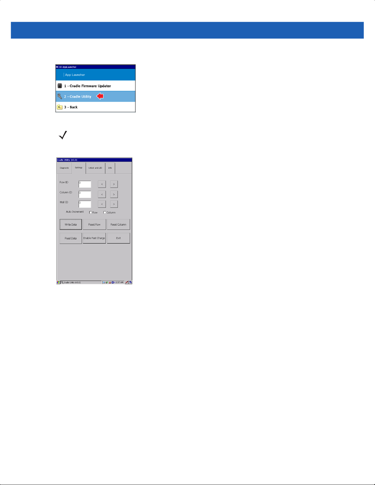
4. On the Cradle Applications menu, tap Cradle Utility.
Special Considerations 6 - 7
Figure 6-3
5. Tap the Settings tab to set the cradle information.
Figure 6-4
Cradle Applications Menu
NOTE The Cradle Utility is also available in the Systems Tools folder on the MC18 desktop.
Cradle Utility - Setting Tab
•
Row ID: The cradle row number in the dispenser wall.
•
Column ID: The cradle column number in the dispenser wall.
•
Wall ID: The number of dispenser wall where the cradle is positioned.
•
Unlock Period: The duration in seconds for which the MC18 remains in unlocked state (if not removed
from the cradle). For example; if unlock period is set to 15 and unlock signal is received, the MC18 will
unlock and lock back after 15 seconds (if its not removed by user).
•
Unlock: Press Unlock to manually unlock the MC18 from the cradle.
•
LED: Check the LED box to enable the cradle LED indication.
•
Smooth Effect: Check the Smooth Effect box to enable LED illumination during unlock.
•
LED Setting > On: The duration (in ms) that the cradle LED is remains turned on or blinks during unlock.
•
LED Setting > Off: The duration (in ms) that the cradle LED is remains turned off or blinks during unlock.
•
LED Setting > Count: The number of times the cradle LED blinks when user presses the blink button.
•
Blink: Tap to test the cradle LED operation.
•
Write Data: Tap this button to program the row/col/wall information onto the cradle. Note that each slot
on the Three Slot Cradle needs to be programmed separately.
Page 68
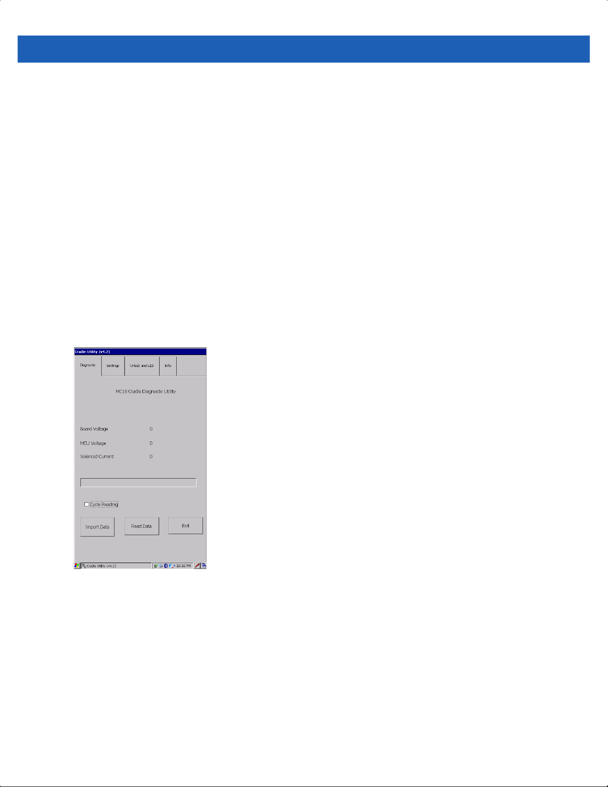
6 - 8 MC18 Product Reference Guide
•
Reset Row: Tap to update the Row ID the text field to “0” on the application.
•
Reset Column: Tap to update the Column ID the text field to “0” on the application.
•
Read Data: Retrieve setting data from the cradle memory and display on the screen.
•
Enable Fast Charge: Enable the cradle to charge the MC18 at a current of 1.5A (default setting is 1A)
•
Exit: Exit the Cradle Applications menu.
Performing Cradle Diagnostics
1. On the home screen of the MC18, double tap the AppLauncher icon.
Result: The App Launcher screen displays.
2. On the AppLauncher screen, double tap Cradle Applications > Cradle Utility.
3. Tap the Diagnostic tab to perform the cradle diagnostics:
a. Cycle Reading: Check the Cycle Reading box to perform continues diagnostics and display the
cradle status information. During diagnostics, a progress bar is shown of the screen.
b. Import Data: Tap to save the recorded results of the diagnostics on a file.
c. Read Data: Tap to start performing diagnostics.
Figure 6-5
Cradle Utility - Diagnostic Tab
Viewing Cradle Information
1. On the home screen of the MC18, double tap the AppLauncher icon.
Result: The App Launcher screen displays.
2. On the AppLauncher screen, double tap Cradle Applications > Cradle Utility.
Page 69
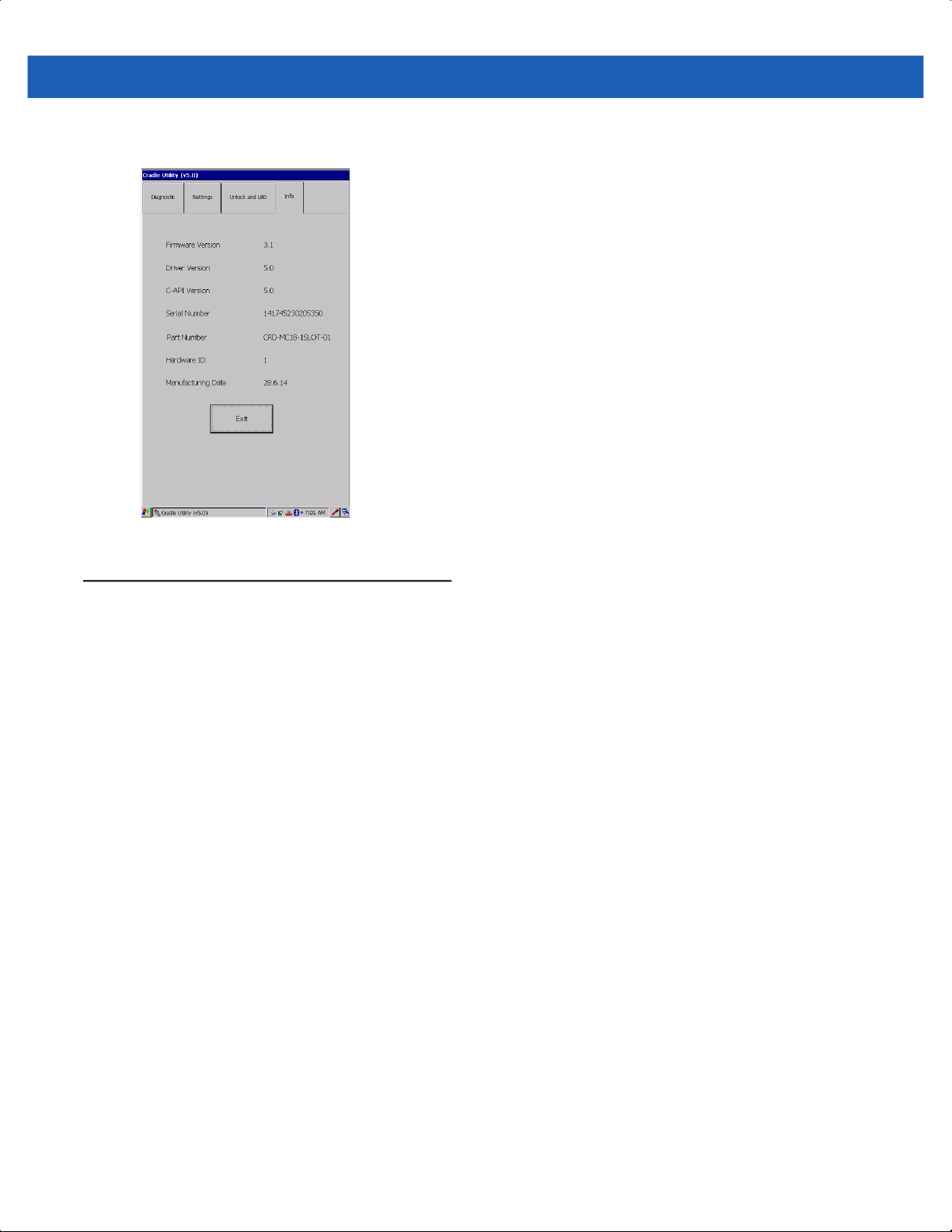
3. Tap the Info tab to read the cradle information.
Special Considerations 6 - 9
Figure 6-6
Cradle Utility - Info Tab
Cradle Firmware Updater
The CradleFWUpdater application enables the manual updating of cradle firmware using the MC18.
To update cradle firmware:
1. Download the MC18CradleFWvx_x firmware file from http://www.zebra.com/support
2. Using a synchronization program, copy the new firmware file to the MC18 (see Chapter 4, Sync with Host
Computer).
Page 70
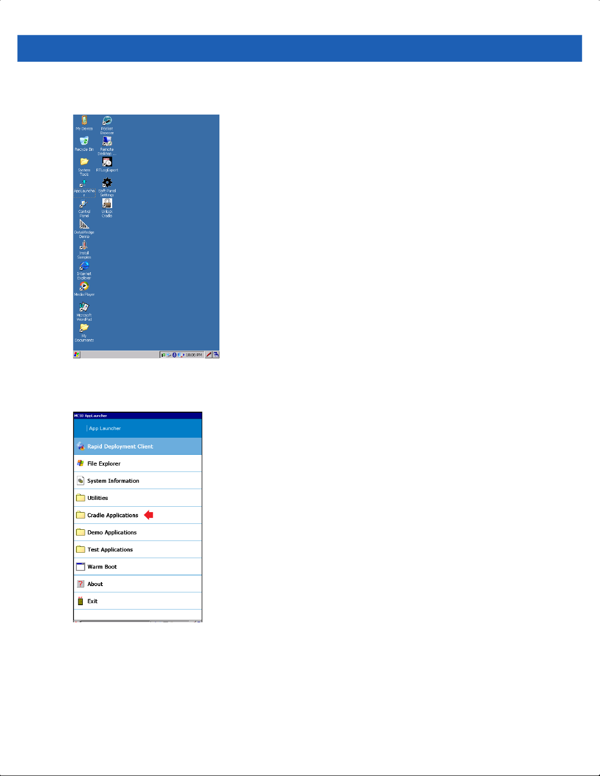
6 - 10 MC18 Product Reference Guide
3. On the home screen of the MC18, double tap the AppLauncher icon. The App Launcher screen displays
on the screen.
Figure 6-7
4. On the App Launcher screen, tap Cradle Applications. The Cradle Applications menu displays
Figure 6-8
MC18 Home Screen
App Launcher Screen
Page 71
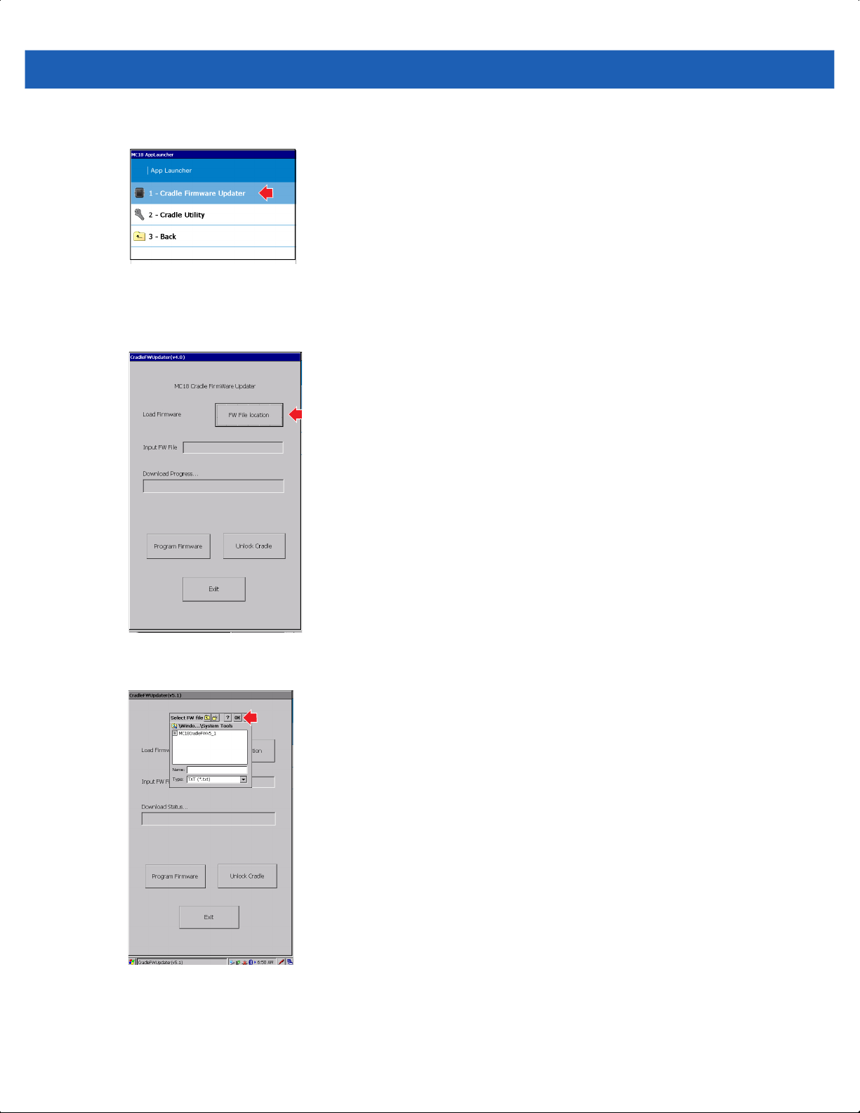
5. On the Cradle Applications menu, tap Cradle Firmware Updater.
Special Considerations 6 - 11
Figure 6-9
6. Dock the MC18 inside the cradle.
7. Tap FW File location. The Select HEX box displays.
Figure 6-10
8. From the Select HEX box, select a firmware file and tap OK.
Cradle Applications Menu
Cradle Firmware Updater - FW File location Button
Figure 6-11
9. Tap Program Firmware. A warning box displays Please don’t remove the device from the cradle until
Cradle Firmware Updater - Select HEX Box
FW Update completes.
Page 72

6 - 12 MC18 Product Reference Guide
10. Tap OK to initiate the firmware update process.
Figure 6-12
NOTE During the firmware initiation process, the application resets the cradle. If the following error box displays:
Perform this procedure to manually reset the cradle:
Cradle Firmware Updater - Don’t Remove Device Warning Box
Please manually rest the cradle and then press “OK” button. The user is required to manually reset
the cradle.
a. Disconnect power from the power supply unit of the cradle.
b. Reconnect power to the power supply unit of the cradle.
c. Tap OK within 10 sec after power on and before the LEDs on the cradle start glowing, to
remove the error message and continue. Failing to tap OK before the LEDs starts glowing will
re-display the error message. If user fails continuously 5 times, the firmware update process
stops.
d. If application is successful, it will start downloading process.
Page 73

Special Considerations 6 - 13
1. After resetting the cradle, the application starts the firmware download process.
Figure 6-13
1. When Download Complete displays on the screen, the firmware update process is completed
Cradle Firmware Updater - Firmware Download Process Screen
DO NOT attempt to disconnect power from the cradle or remove the MC18 from the cradle during cradle firmware
update. Removing the MC18 from the cradle while firmware update is ongoing would result in an incomplete
firmware update, leaving the cradle with partial firmware.
To recover from situation of partial downloaded firmware, open the Cradle Firmware Updater application (see
Cradle Firmware Updater on page 6-9) and perform manual reset of the cradle power when alerted.
successfully. Tap Unlock Cradle to unlock and remove the MC18 from the cradle.
Figure 6-14
Cradle Firmware Updater - Download Complete Screen
MC18 Diagnostics
The MC18 diagnostics engine provides software interfaces for applications to read diagnostics information.
The diagnostics test application is used to display the results of the diagnostics test.
Page 74

6 - 14 MC18 Product Reference Guide
To view the results of the diagnostics test on the MC18:
NOTE MC18 diagnostics can also be performed through the Pocket Browser application. MC18 uses software
interfaces exposed via EMDK and pocket browser plugins to retrieve the MC18 diagnostics information.
1. On the App Launcher screen, tap Test Applications. The Test Application menu displays.
Figure 6-15
2. Tap DiagnosticApp. The Diagnostic Test App screen displays with the updated test information.
Test Applications Menu
Figure 6-16
Diagnostic Test App Screen
Page 75

Soft Button Panel
The Soft Button Panel application enables the creation of soft button panel at the lower part of the MC18
screen. The soft button panel includes three buttons that can be customized to perform the following basic
keyboard operations:
•
Up
•
Down
•
Escape (Esc)
•
Enter
•
Left
•
Right
Use this procedure to create and configure a soft button panel:
1. From the home screen of the MC18, tap Start > Programs > Soft Panel Settings.
Special Considerations 6 - 15
Figure 6-17
2. Check the Enable Soft Key box to enable settings.
3. Using the provided pallets, select the soft keys panel, buttons and pallet color.
4. Scroll to the bottom of the window and type the text that will display on each button.
5. Use the drop menu to select the operation of each button.
6. Tap Save.
Soft Panel Settings Window
Page 76

6 - 16 MC18 Product Reference Guide
Page 77

CHAPTER 7 POCKET BROWSER
Introduction
This feature-rich, mobile application development tool is designed to allow Web developers to rapidly create
robust mobile applications that can include a wide range of advanced data capture capabilities. Whether you
want to streamline your warehouse, delivery or service operations, or enable more robust asset tracking or
visibility, Pocket Browser will help you get your enterprise mobility solution up and running faster — and more
cost efficiently.
The Pocket Browser Developer Help provides detailed information about how to use each feature of the
browser. Each feature includes a sample for you to use, however, please be aware that the sample does not
necessarily show the only way to implement each feature.
Pocket Browser enables developers and integrators to provide advanced Web-based solutions to select
Microsoft® Windows Mobile and Windows CE mobile computers. PocketBrowser makes the most of
enterprise-level applications while speeding up development time and reducing costs. With it, making the
transition to web-based solutions is now fast, easy and affordable - especially in high-volume mobile
environments.
Pocket Browser is a software tool that extends the core rendering engine functionality of Microsoft PocketIE or
Microsoft IE with Symbol Technologies application programming interfaces (APIs). It provides interfaces to the
MC18 hardware and features using meta tags and Microsoft ActiveX® components designed specifically for
Symbol Technologies systems. Pocket Browser offers easy integration with bar code scanners, RFID readers
and other peripherals such as printers and magnetic stripe readers (MSR) for complete transaction processing.
Sample Application
The MC18 comes with a sample PocketBrowser v 3.1.0 applications factory-installed. The sample application
is accessible from the Programs menu.
To start PocketBrowser, select Start > Programs > Pocket Browser. The PocketBrowser window appears.
Page 78

7 - 2 MC18 Product Reference Guide
Battery Status Indicator
Wireless Signal Strength Indicator
Figure 7-1
The sample PocketBrowser provides the following information:
•
•
•
•
The three buttons at the bottom of the screen:
•
•
•
Sample PocketBrowser Screen
Battery level status bars
WLAN signal strength status bars
Battery Details:
• Battery strength in percentage
• Battery change / no charge status
WLAN details:
• ESSID name
• Signal
• IP Address of the MC18
• MAC address of the MC18
UNLOCK/LOCK - Unlocks and locks the MC18 into the cradle
LEDS - Illuminates the cradle LEDs
QUIT - Exits the sample PocketBrowser application
Configuring the Pocket Browser
The information on the Pocket Browser startup page can be configured by changing the Config.xml file (from
the MC18 root directory, select Program Files > PocketBrowser > Config > Config.xml). Before launching
the Pocket Browser for configuration, the MC18 must be connected to a network.
Page 79

CHAPTER 8 CRADLE
INSTALLATION
Introduction
A typical Personal Shopper system is comprised of a family of hardware devices interconnected through a
WLAN radio backbone to the retail establishment’s server(s). The hardware devices are the MC18 mobile
computers, single-slot or Three Slot Cradles, power supplies and cables. A dispenser typically refers to a piece
of furniture which has mounted to it the cradles, their power supplies, and cables.
Customers (retail establishments) design their own dispensers to meet their particular floor space and display
requirements. The information in this chapter should help a customer to design a dispenser and to understand
the installation requirements.
IMPORTANTThe MC18 cradles are NOT compatible with MC17 cradles and the MC17 cradles are NOT compatible with
MC18 cradles.
Installation of the Single Slot Cradle
Installation of the Single Slot Cradle include the following mounting steps:
•
Select the charging mode (see Charging Modes on page 8-1)
•
Mount the Single Slot Cradles on a dispenser wall (see Mounting the Single Slot Cradle on a Dispenser
Wall on page 8-2)
•
Connect the wires to the cables (see Wiring on page 8-4)
•
Set the cradle(s) (see Setting and Controlling the Cradle on page 6-5)
Charging Modes
Single Slot Cradles can be installed in the following charging modes:
•
Standard charging
•
Fast charging
There are some general charging considerations that must be taken into account when designing a dispenser
and ordering hardware elements of a system:
Page 80
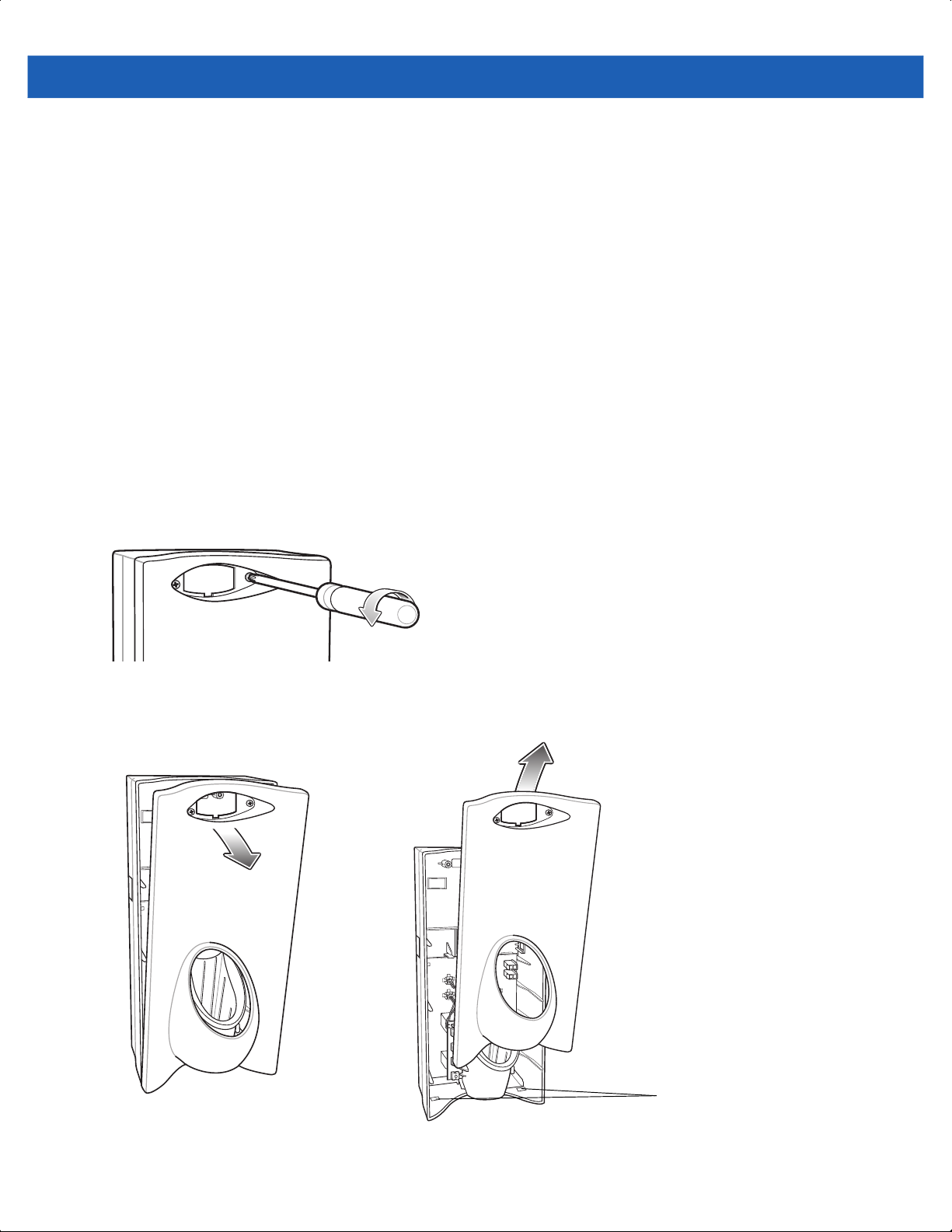
8 - 2 MC18 Product Reference Guide
Standard Charging Mode
•
In standard charging mode, no more than 12 cradles can be powered off of one power supply unit (p/n
PWRS-14000-241R) using “Y” power cable 25-67592-01R.
•
In standard charging mode, the current draw by each docked MC18 can reach a maximum of 1A.
Fast Charging Mode
•
In fast charging mode, no more than six cradles can be powered off of one power supply unit (p/n
PWRS-14000-241R) using power cable 25-66420-01R.
•
In fast charging mode, the current draw by each docked MC18 can reach a maximum of 1.5A.
Mounting the Single Slot Cradle on a Dispenser Wall
The cradle contains two mounting holes in the back housing so that it can be hanged on screws fixed to a
supporting furniture. In addition, it comes with plugs and a variety of cable routing outlets. Figure 8-3 provides
the necessary information about the location and dimensions of the mounting holes of the cradle.
To mount the Single Slot Cradle:
1. Loosen two captive screws securing the front cover to the base.
Figure 8-1
2. Pull front cover away from base and then lift out of the base.
Remove Screws
Alignment Holes
Figure 8-2
Cover Removal
Page 81

3. Use two screws to hang the cradle on a wall.
8.5mm
(0.33”)
4mm
(0.16”)
Cradle Installation 8 - 3
127 mm ± 0.4 mm
(5.0” ± 0.02”)
Two Mounting Holes
162.5 ± 0.2 mm
(6.39” ± 0.01”)
20.5 mm
(0.80”)
271.8 mm ± 0.7 mm
(10.70” ± 0.03”)
86 ± 0.2 mm
(3.39 ± 0.01”)
Figure 8-3
Hanging the Cradle on a Wall - Mounting Template
Page 82

8 - 4 MC18 Product Reference Guide
Depth of cradle:
99 mm
(3.9”)
Figure 8-4
Overall Depth of Cradle
Wiring
NOTE During installation ensure all interconnect cables are fully enclosed within the power supply or cradle enclosure.
1. Install power supply, including AC line cord and power cable, into Decorative Housing.
Power Supply PWRS-14000-241R
(inside Decorative Housing)
Power Cable 25-66420-01R
Figure 8-5
Connecting Power Supply
Page 83
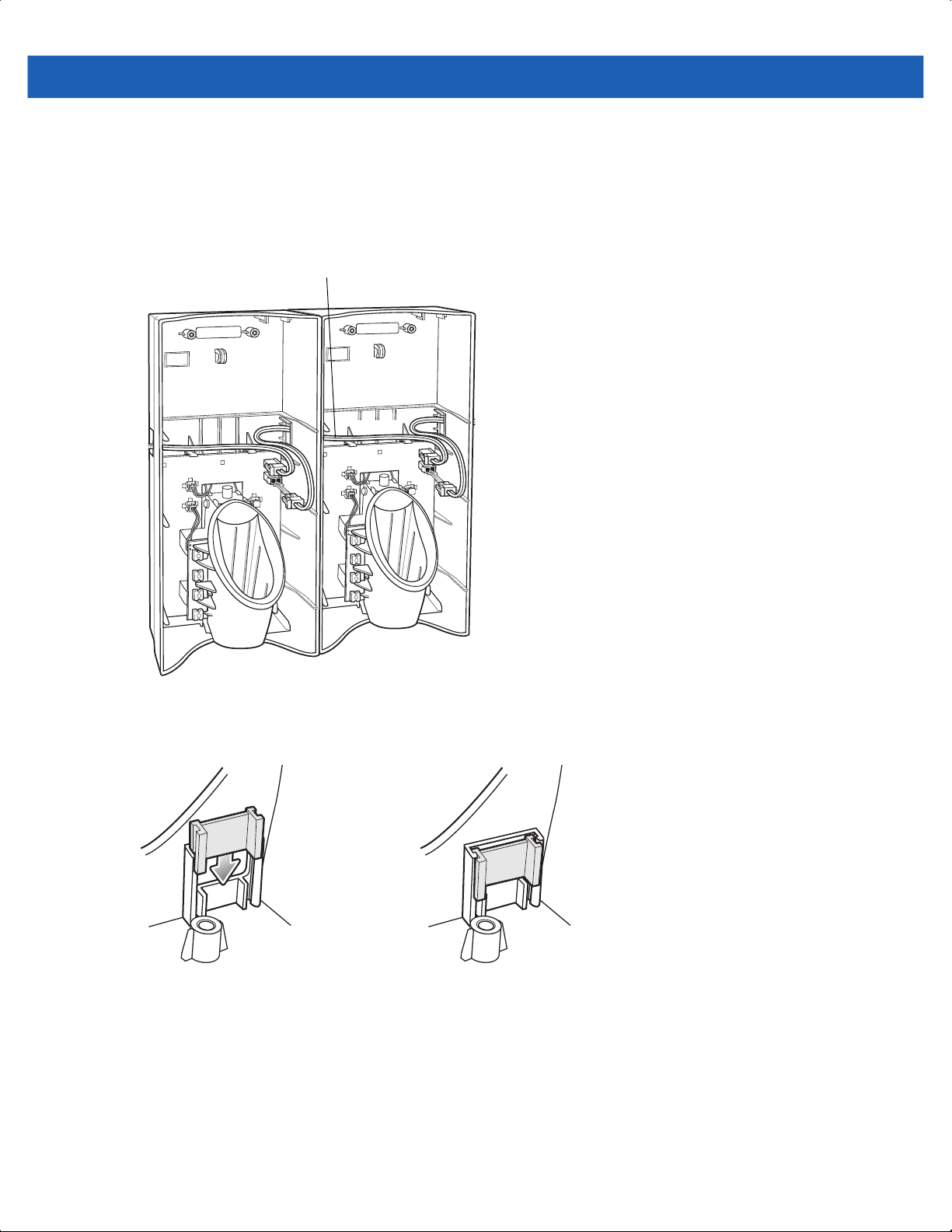
Cradle Installation 8 - 5
2. Insert power cable through a cable outlet of cradle back housing.
3. Plug connector into power connector on printed circuit board.
4. If more than one cradle is being installed, connect the interconnect cable from the first cradle to the second
cradle.
Interconnect Cable 25-66431-01R
Figure 8-6
5. Use plugs to cover un-used cable outlets.
Figure 8-7
Daisy-Chaining Cradles
Cable Hole Plug Installation
Assembly
1. Replace cover.
2. Secure cover with screws.
Page 84

8 - 6 MC18 Product Reference Guide
Figure 8-8
3. Insert bar code target cover.
4. Push target cover into front cover until it snaps into place.
Figure 8-9
Replace Cover
NOTE Do not install the target cover until you are sure that you do not need to remove the front cover again.
Replace Target Bar Code Cover
Page 85

Cradle Installation 8 - 7
System Cabling
There are some general limitations that must be taken into account when designing a dispenser and ordering
hardware elements of a Personal Shopper system:
•
No more than six cradles can be powered off each leg of the “Y” power cable.
•
A power supply cable runs from the power supply to one or two cradles.
•
Cradle interconnection cables run between each successive cradle in the chain.
•
The power supply is air cooled, and as such expects some circulation of fresh air around it. Do not
enclose it in a small airtight location.
•
Power supplies must be mounted in their natural, landscape orientation. They contain fans and their
vents must allow for the free flow of air.
•
Power supplies should be mounted either above or below dispensers and entrance heads. Mounting of
power supplies to the right or left is not preferred.
•
When laying out your furniture and cabling plan, routing should be as direct as possible. Routing should
follow vertical and horizontal runs through the modules. A set of labels, numbered 1 to 12, is part of each
power supply unit. These labels are to be used to track the number of loads on a particular supply. Each
label is designed to be attached to the cradle interconnection cable when a cradle is added to the daisy
chain. When all labels are used, the supply is fully loaded.
Figure 8-10 shows how the maximum number of cradles can be cabled to a power supply using power cable
25-66420-01R.
Figure 8-11 shows how the maximum number of cradles can be cabled to a power supply using the “Y” power
cable 25-67592-01R. Note that there are only six cradles per leg of the power supply cable, and only 12
cradles in total.
Figure 8-10
Maximum Number of Charge Cradles per Power Supply
Page 86
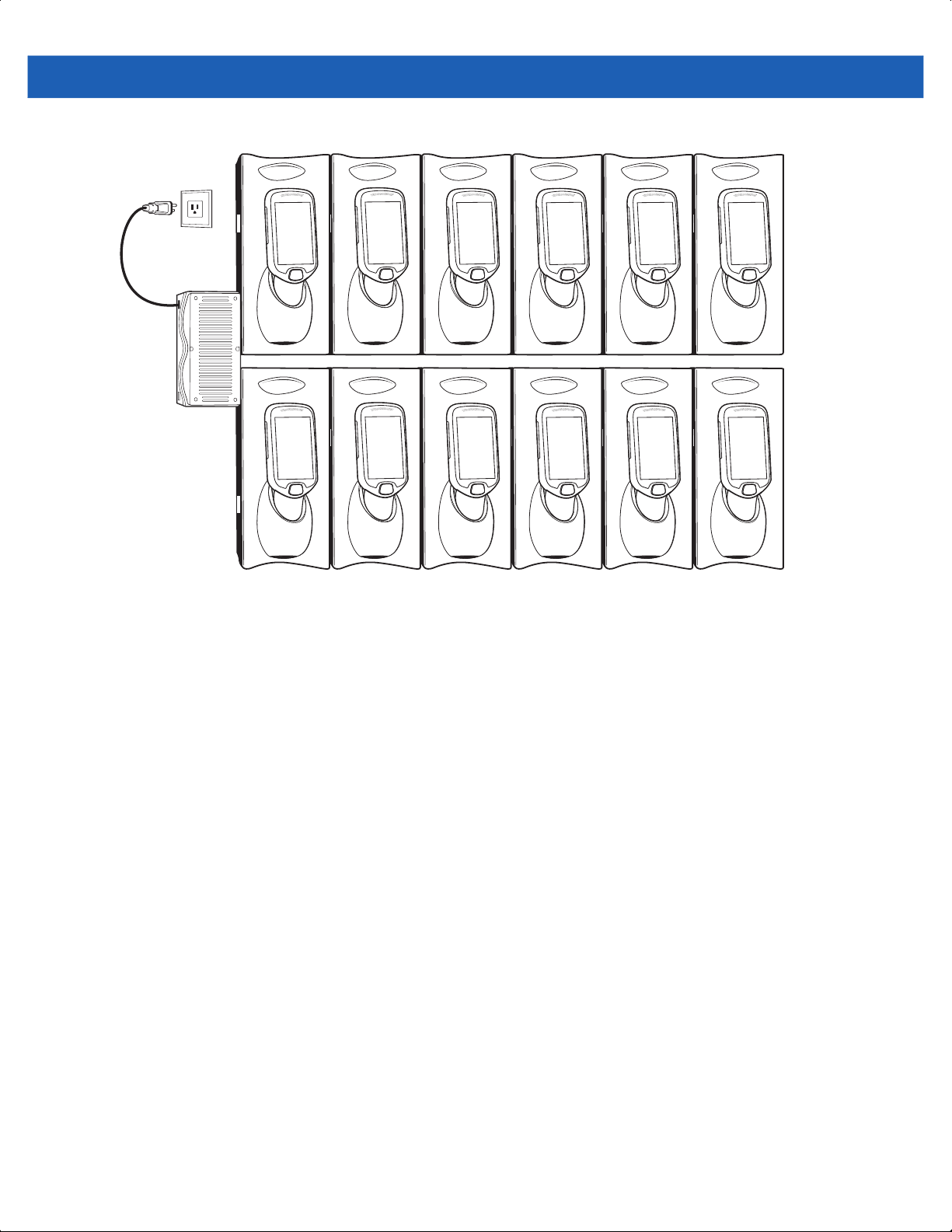
8 - 8 MC18 Product Reference Guide
Figure 8-11
Maximum Number of Charge Cradles per Power Supply with “Y” Power Cable
Page 87

Installation of the Three Slot Cradle
Installation of the Three Slot Cradle include the following mounting steps:
•
Select the mounting configuration (see Mounting Configurations on page 8-9)
•
Select the charging mode (see Charging Modes on page 8-11)
•
Mount the Three Slot Cradles on a dispenser wall (see Mounting the Three Slot Cradle on a Dispenser
Wall on page 8-14)
•
Mount the power supply unit (see Mounting the Power Supply Unit on page 8-18)
•
Set the cradle(s) (see Setting and Controlling the Cradle on page 6-5)
Mounting Configurations
Three slot cradles can be installed in the following mounting configurations:
•
High Density (HD) configuration - Using HD cradles
•
Super High Density (SHD) configuration - Using SHD cradles
Cradle Installation 8 - 9
•
Desktop configuration - Using stand alone cradle(s) on a flat surface
High Density Configuration
The cradle can be installed in high density configuration so that the display of the MC18 devices are facing the
user. In this configuration, cradles are installed with a vertical gap of 35mm between each other.
NOTE In high density configuration, the MC18 units have a 10-degree forward-facing tilt that should be taken in
consideration, especially if furniture is planned to be placed in front of the dispenser wall.
35mm
Figure 8-12
Installation in High Density Configuration
Page 88

8 - 10 MC18 Product Reference Guide
The installation of the dispenser wall can be designed so that it tilts slightly backward in the following angles:
274 mm
0
°
Figure 8-13
Super High Density Configuration
The cradle can be installed in super high density configuration so that the display of the MC18 devices are
facing up. In such configuration, cradles are installed with a vertical gap of 7mm from each other to allow more
cradles per square meter.
Dispenser Wall Angles
301 mm
5
°
387 mm
10
°
499 mm
10
°
7mm
Figure 8-14
Installation in Super High Density Configuration
Page 89
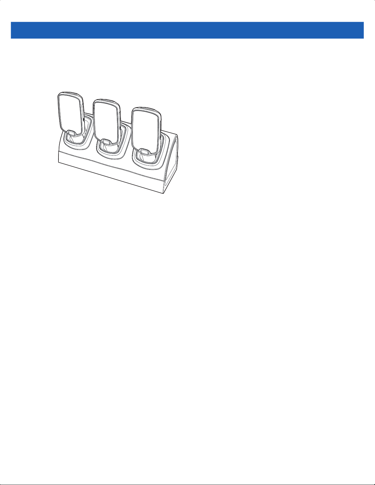
Cradle Installation 8 - 11
Desktop Configuration
In desktop configuration, the cradle can be placed on a flat tabletop or shelf at checkout or back room
locations.
Figure 8-15
Installation in Desktop Configuration
Charging Modes
Three Slot Cradles can be installed in the following charging modes:
•
Standard charging
•
Fast charging
There are some general charging considerations that must be taken into account when designing a dispenser
and ordering hardware elements of a system:
Standard Charging Mode
•
In standard charging mode, no more than four cradles can be powered off of one power supply unit (p/n
PWRS-14000-241R) using “Y” power cable (p/n 25-67592-01R or p/n 25-66210-01R), power extension
cables (p/n CBL-MC18-EXINT1-01) and interconnect cables (p/n 25-66431-01R).
•
In standard charging mode, the current draw by each docked MC18 can reach a maximum of 1A.
•
Cable routing should be as direct as possible. Routing should follow vertical and horizontal runs through
the modules.
Page 90

8 - 12 MC18 Product Reference Guide
Figure 8-16 shows how the four cradles can be cabled to a power supply unit in standard charging mode.
Power Supply Unit
PWRS-14000-241R
Power Extension Cable
(p/n
CBL-MC18-EXINT1-01)
Interconnect Cable
(p/n 25-66431-01R)
Cradle Interconnection Extension
Cable (p/n CBL-MC18-EXINT1-01)
Interconnect Cable
(p/n 25-66431-01R)
“Y” Power Cable: 25-67592-01R
or 25-66210-01R or
CBL-MC18-Y2MET-01
Cradle Interconnection Extension
Cable (p/n CBL-MC18-EXINT1-01)
Figure 8-16
Standard Charging Mode - Cable Connections
Fast Charging Mode
•
In fast charging mode, no more than three cradles can be powered off of one power supply unit (p/n
PWRS-14000-241R) using “Y” power cable (p/n 25-67592-01R or p/n 25-66210-01R or
CBL-MC18-Y2MET-01), Interconnect cables (p/n 25-66431-01R) and cradle interconnection extension
cables (p/n CBL-MC18-EXINT1-01).
•
In fast charging mode, the current draw by each docked MC18 can reach a maximum of 1.5A.
•
Cable routing should be as direct as possible. Routing should follow vertical and horizontal runs through
the modules.
Figure 8-17 shows how the three cradles can be cabled to a power supply unit in fast charging mode.
Page 91

Power Supply Unit
PWRS-14000-241R
Power Extension Cable
(p/n
CBL-MC18-EXINT1-01)
Cradle Installation 8 - 13
Interconnect Cable
(p/n 25-66431-01R)
Cradle Interconnection Extension
Cable (p/n CBL-MC18-EXINT1-01)
“Y” Power Cable: 25-67592-01R or 25-66210-01R
or CBL-MC18-Y2MET-01
Figure 8-17
Fast Charging Mode Cable Connections
Page 92
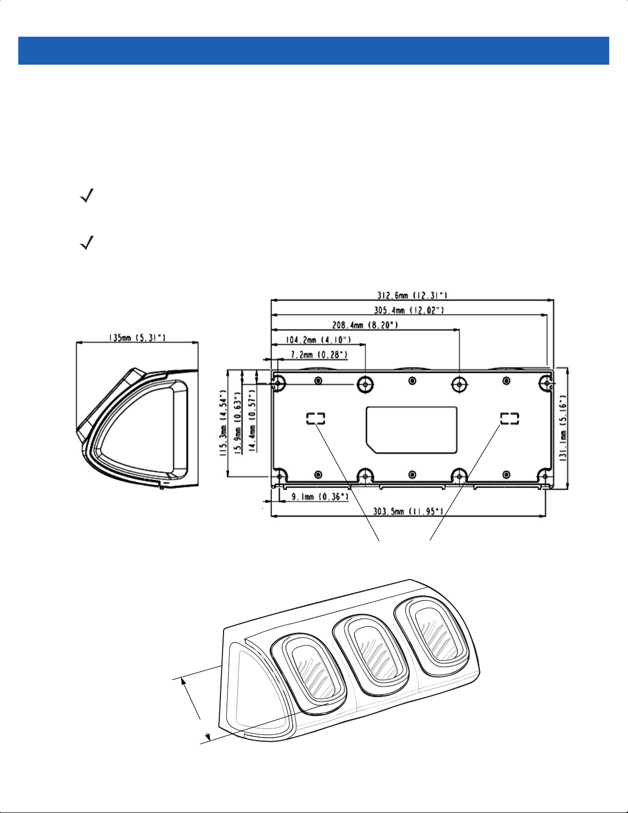
8 - 14 MC18 Product Reference Guide
Mounting the Three Slot Cradle on a Dispenser Wall
The cradle can be bolted to a dispenser wall or any supporting furniture using eight mounting holes. The back
cover of the cradle has two access holes for routing power cables to \ from a power supply unit or adjacent
cradle. Figure 8-18 provides a mounting template for cradle installation.
Perform this procedure to mount the cradle on a dispenser wall:
CAUTION DO NOT connect more than four cradles when is standard charging mode or three cradles when in fast
charging mode to a single power supply unit.
DO NOT connect the power supply unit to a power outlet until all installation steps are completed.
NOTE The following procedure is an example installation of Three Slot Cradles in fast charging mode - high
density configuration.
1. Use the wall mount template to plan and mark the screw locations on the dispenser wall.
Depth of cradle 125 mm (3.9”)
Figure 8-18
Three Slot Cradle - Mounting Template and Overall Depth
Access Holes
Page 93

Cradle Installation 8 - 15
2. In all cradles, plug the power extension cable (p/n CBL-MC18-EXINT1-01) to free the connector on left
slot.
3. Plug interconnect cable (p/n 25-66431-01R) to free connector on right slot.
Cradle Interconnection Extension Cable
Interconnect Cable
(p/n 25-66431-01R)
(p/n CBL-MC18-EXINT1-01)
Figure 8-19
4. On all the back covers, knock-out the stamped access hole(s).
Figure 8-20
5. Route interconnect cables through access holes in back covers.
Three Slot Cradle - Cable Connections
Stamped Access Hole(s)
Three Slot Cradle - Stamped Access Hole(s)
Figure 8-21
Three Slot Cradle - Back Cover Cable Routes
Page 94

8 - 16 MC18 Product Reference Guide
6. Secure the back cover of each cradle using six T10 Torx screws (supplied). Torque screws to 6 Kgf-cm (5.2
in-lb).
Figure 8-22
7. Insert the front cover removal tool into two slots, lever upwards and pull to remove front cover from cradle.
Figure 8-23
8. Position the cradle on the dispenser wall and route all interconnect cables through the access holes in the
Three Slot Cradle - Securing the Back Cover
Three Slot Cradle - Removing Front Cover
dispenser wall.
9. Fasten the cradle to the wall using eight screws (not supplied). Make sure to use additional wall mounting
hardware, as needed, for safe mounting, according to the wall type.
Figure 8-24
Three Slot Cradle - Fastening the Cradle to a Wall
Page 95

Cradle Installation 8 - 17
10. Insert tabs on upper side of front cover into slots on cradle and rotate cover down until it snaps into place.
1
2
Figure 8-25
11. Plug Power Extension Cable (p/n CBL-MC18-EXINT1-01) to interconnect cable (p/n 25-66431-01R).
12. Plug “Y” cable (25-67592-01R) to Interconnect cables (p/n 25-66431-01R).
13. Plug “Y” cable (25-67592-01R) to power supply unit.
14. Secure power supply unit (p/n PWRS-14000-241R) to the back of the dispenser wall.
Three Slot Cradle - Connecting the Front Cover
Page 96

8 - 18 MC18 Product Reference Guide
15. Connect the power cord to the power supply unit and to a 110/220 VAC outlet.
Power Extension Cable
(p/n CBL-MC18-EXINT1-01)
Interconnect Cable
(p/n 25-66431-01R)
Cradle Interconnection Extension Cable
(p/n CBL-MC18-EXINT1-01)
Power Supply Unit (PWRS-14000-241R)
Figure 8-26
16. Place the socket onto the cradle and secure the four screws.
17. Place the socket cover onto the cradle and secure the two screws.
Three Slot Cradle - Connection to Power Supply Unit
DC “Y” Charging Cable Long (25-67592-01R)
Mounting the Power Supply Unit
IMPORTANTThe power supply unit is air cooled and requires circulation of free air around it. Do not enclose it in a
small airtight enclosure other than plastic housing, p/n PSS-3PS04-00R.
The power supply can be housed in an optional plastic housing, p/n PSS-3PS04-00R, to match the cradles and
hide bare power supplies and cables. This section provides the information required to mount the plastic
housing.
Page 97

Cradle Installation 8 - 19
UP
To install the power supply unit inside the plastic housing:
1. Use the mounting template of the power supply housing to plan and mark the screw locations on the
dispenser wall.
68.4 mm
(2.693”)
135.9 mm
(5.35”)
254.0 mm
(10.00”)
(View from Inside Housing)
The depth of the fully-assembled power supply decorative housing is 81.23 mm (3.198”).
Figure 8-27
Power Supply Housing Mounting Template
109.4 mm
(4.307”)
115.9 mm
(4.562”)
10 mm
(0.394”)
38.1 mm
(1.50”)
2. Feed cables through access holes in bottom housing.
3. Plug connectors into power supply.
4. Place power supply into bottom housing.
5. Place two mounting brackets over power supply and secure each mounting bracket with two screws.
Page 98
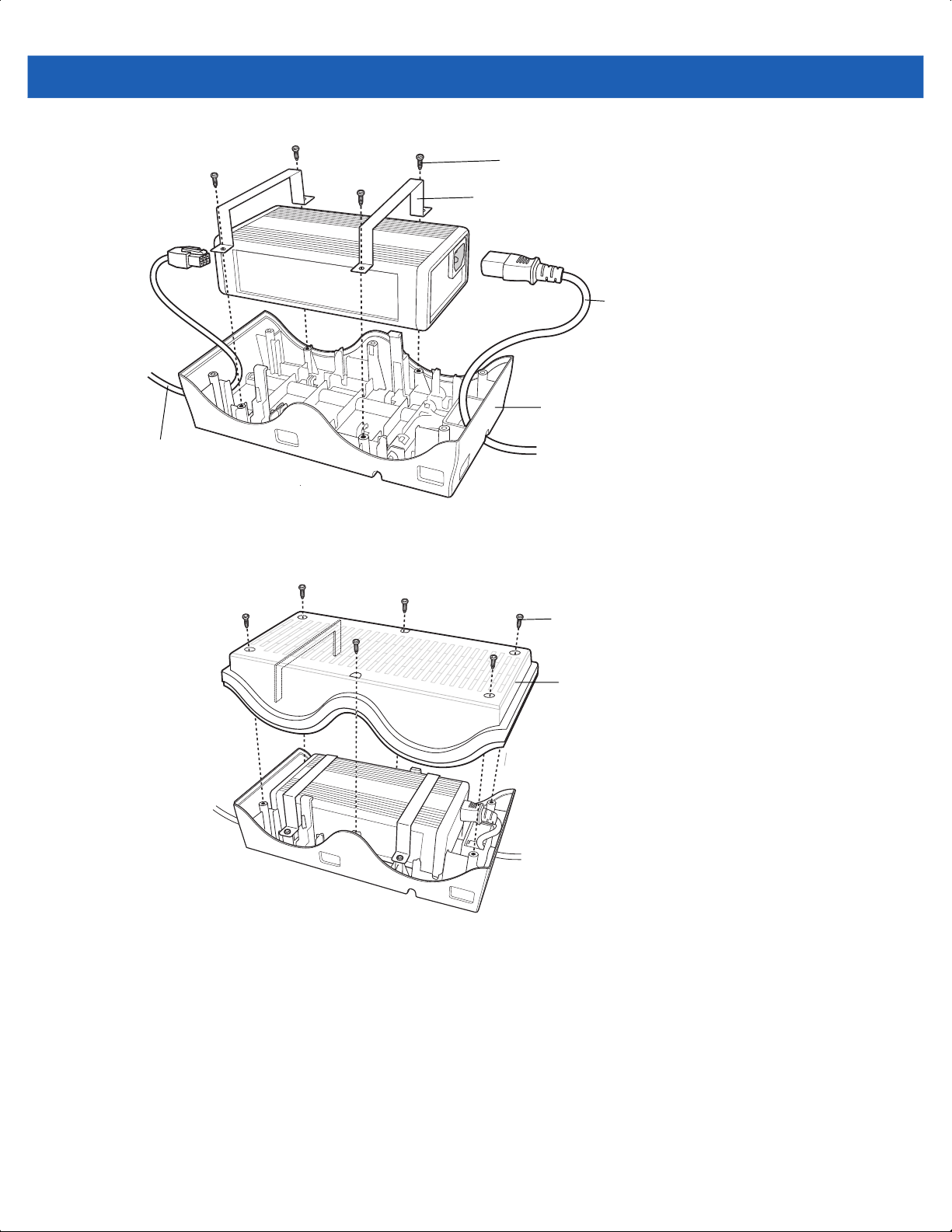
8 - 20 MC18 Product Reference Guide
Output Cable
Screws
Mounting bracket
AC line Cord
Bottom Housing
Figure 8-28
6. Align top housing over bottom housing and secure using six screws.
Figure 8-29
Power Supply Assembly
Screws
Top Housing
Top Housing Installation
Page 99

CHAPTER 9 APPLICATION
DEPLOYMENT
Software Installation on Development PC
To develop applications to run on the MC18, use one or all of the following:
•
Microsoft Visual Studio 2005/2008
•
Enterprise Mobility Developer Kit (EMDK) for C/C++
•
Enterprise Mobility Developer Kit (EMDK) for .NET
•
Enterprise Mobility Developer Kit (EMDK) for Pocket Browser
•
Windows CE Platform PSDK for MC18No
•
Active Sync v4.5/ WMDC v6.1
The Windows CE Platform SDK for the MC18c70BenPS060000.msi is used in conjunction with the EMDK for
C to create Windows CE applications for the MC18. The Platform SDK installs a new Windows CE device type
and its associated libraries onto the development PC.
Platform SDK
Different Platform SDKs are required for the Microsoft® Windows CE 7.0 Professional Core platforms.
Use this procedure to download and install the appropriate Platform SDK:
1. Download the appropriate Platform SDK from the Support Central web site, http://www.zebra.com/support:
a. On http://www.zebra.com/support select Software Downloads.
b. Select Mobile Computers and then select MC18.
c. Select the Platform SDK.
d. Save the .exe file to the development computer.
NOTE MC18 PSDK.exe file can not be installed on windows 2008 server. Use an.msi version of the file on
windows 2008 server.
2. Run the file and follow the screen prompts to install.
Page 100

9 - 2 MC18 Product Reference Guide
Enterprise Mobility Developer Kits
Use this procedure to install an EMDK:
1. Download the EMDK from the Support Central web site, http://www.zebra.com/support:
a. On http://www.zebra.com/support, select Developer Downloads and sign in.
b. Select Mobile Computers and then select MC18.
c. Select the latest version of the Enterprise Mobility Developer Kit.
d. Download the .exe file to the development computer.
2. Double-click the executable file and follow the install screen prompts.
Installing Other Development Software
Developing applications for the MC18 may require installing other development software such as application
development environments on the development PC. Follow the installation instructions provided with this
software.
 Loading...