

Page 1
MC18
MN-002953-02
Personal Shopper
Product Reference Guide
for Android Version 5.1.1
Page 2

Page 3

MC18 WITH ANDROID™ OS 5.1.1
PRODUCT REFERENCE GUIDE
MN-002953-02
Rev . A
March 2018
Page 4

ii MC18 with Android OS Product Reference Guide
Page 5

Revision History
Changes to the original guide are listed below:
Change Date Description
-01 Rev A 12/1/16 Initial release.
-02 Rev A 3/1/18 Update ESD specification.
iii
Page 6

iv MC18 with Android OS Product Reference Guide
Page 7

TABLE OF CONTENTS
Revision History................................................................................................................................. iii
About This Guide
Introduction...................................................................................................................................... xiii
Documentation Set .......................................................................................................................... xiii
Configurations.................................................................................................................................. xiii
Software Versions...................................................................................................................... xiv
Chapter Descriptions ....................................................................................................................... xiv
Notational Conventions.................................................................................................................... xv
Related Documents and Software................................................................................................... xv
Service Information.......................................................................................................................... xv
Chapter 1: Getting Started
Introduction .................................................................................................................................... 1-1
Unpacking ................................................................................................................................ 1-1
Removing the Screen Protection Film ...................................................................................... 1-1
Features ......................................................................................................................................... 1-2
Accessories .................................................................................................................................... 1-4
Scan Key ........................................................................................................................................ 1-7
Getting Started ............................................................................................................................... 1-8
Installing the Battery ...................................................................................................................... 1-8
Removing the Battery ............................................................................................................... 1-9
Charging the Battery .............................................................................................................. 1-10
Powering On ................................................................................................................................ 1-12
Manual Release of MC18 from Cradles ....................................................................................... 1-13
Software Release ................................................................................................................... 1-13
Manual Release of MC18 from the Single Slot Cradle ........................................................... 1-13
Manual Release of MC18 from the Three Slot Cradle ........................................................... 1-13
Battery Management .................................................................................................................... 1-14
Monitor Battery Usage ........................................................................................................... 1-14
Low Battery Notification ......................................................................................................... 1-15
Battery Optimization ............................................................................................................... 1-15
Page 8

vi MC18 with Android OS Product Reference Guide
Battery Diagnostics ................................................................................................................ 1-15
Turning Off the Radios ........................................................................................................... 1-16
Setting the Date and Time ........................................................................................................... 1-16
Display Setting ............................................................................................................................. 1-17
Setting the Screen Brightness ................................................................................................ 1-17
Setting Screen Timeout Setting ............................................................................................. 1-17
Setting Font Size .................................................................................................................... 1-18
Sound ..................................................................................................................................... 1-19
Notification ............................................................................................................................. 1-21
Performing a Soft Reset ......................................................................................................... 1-22
Performing a Hard Reset ....................................................................................................... 1-22
When in a Cradle ............................................................................................................. 1-22
When Out of the Cradle ................................................................................................... 1-22
Performing an Enterprise Reset ............................................................................................. 1-23
Performing a Factory Reset ................................................................................................... 1-24
Chapter 2: Using the MC18
Introduction .................................................................................................................................... 2-1
Home Screen ................................................................................................................................. 2-1
Status Bar ................................................................................................................................ 2-2
Status Icons ....................................................................................................................... 2-3
Notification Icons ...................................................................................................................... 2-4
Managing Notifications ............................................................................................................. 2-5
Quick Settings .......................................................................................................................... 2-5
Application Shortcuts and Widgets .......................................................................................... 2-6
Adding an Application or Widget to the Home Screen ....................................................... 2-6
Moving Items on the Home Screen .................................................................................... 2-6
Removing an App or Widget from the Home Screen ......................................................... 2-6
Folders ..................................................................................................................................... 2-7
Creating a Folder ............................................................................................................... 2-7
Naming Folders .................................................................................................................. 2-7
Removing a Folder ............................................................................................................. 2-7
Home Screen Wallpaper .......................................................................................................... 2-7
Changing the Home Screen Wallpaper .............................................................................. 2-7
Using the Touchscreen ............................................................................................................ 2-8
Using the On-screen Keyboard ................................................................................................ 2-8
Editing Text .............................................................................................................................. 2-8
Entering Numbers, Symbols and Special Characters .............................................................. 2-8
Applications .................................................................................................................................... 2-9
Accessing Applications .................................................................................................... 2-11
Switching Between Recent Applications .......................................................................... 2-11
Un-Locking the Screen ........................................................................................................... 2-12
Single User Mode ............................................................................................................. 2-12
MultiUser Mode ...................................................................................................................... 2-14
MultiUser Login ...................................................................................................................... 2-14
MultiUser Logout .............................................................................................................. 2-15
Suspend Mode ............................................................................................................................. 2-15
Page 9

Table of Contents vii
Chapter 3: Wireless
Wireless Local Area Networks ....................................................................................................... 3-1
Scan and Connect to a Wi-Fi Network ..................................................................................... 3-1
Configuring a Wi-Fi Network .................................................................................................... 3-3
Manually Adding a Wi-Fi Network ............................................................................................ 3-4
Configuring for a Proxy Server ................................................................................................. 3-5
Configuring the Device to Use a Static IP Address .................................................................. 3-6
Advanced Wi-Fi Settings .......................................................................................................... 3-6
Additional Settings ................................................................................................................... 3-7
Remove a Wi-Fi Network ......................................................................................................... 3-8
Wi-Fi Advanced Features .............................................................................................................. 3-9
Zebra Mobility Extensions .............................................................................................................. 3-9
Bluetooth ...................................................................................................................................... 3-10
Adaptive Frequency Hopping ................................................................................................. 3-10
Security .................................................................................................................................. 3-10
Bluetooth Profiles ................................................................................................................... 3-11
Bluetooth Power States .......................................................................................................... 3-11
Bluetooth Radio Power .......................................................................................................... 3-11
Enabling Bluetooth ........................................................................................................... 3-11
Disabling Bluetooth .......................................................................................................... 3-12
Discovering Bluetooth Device(s) ............................................................................................ 3-12
Changing the Bluetooth Name ............................................................................................... 3-12
Connecting to a Bluetooth Device .......................................................................................... 3-13
Selecting Profiles on the Bluetooth Device ............................................................................ 3-13
Unpairing a Bluetooth Device ................................................................................................. 3-13
Chapter 4: Applications
Introduction .................................................................................................................................... 4-1
Battery Manager ............................................................................................................................ 4-1
File Browser ................................................................................................................................... 4-2
Contacts ......................................................................................................................................... 4-3
Adding Contacts ....................................................................................................................... 4-3
Editing Contacts ....................................................................................................................... 4-3
Deleting Contacts ..................................................................................................................... 4-3
Gallery ............................................................................................................................................ 4-4
Working with Albums ................................................................................................................ 4-5
Share an Album ................................................................................................................. 4-5
Get Album Information ....................................................................................................... 4-5
Deleting an Album .............................................................................................................. 4-5
Working with Photos ................................................................................................................ 4-6
Viewing and Browsing Photos ............................................................................................ 4-6
Cropping a Photo ............................................................................................................... 4-6
Setting a Photo as a Contact Icon ...................................................................................... 4-7
Share a Photo .................................................................................................................... 4-7
Deleting a Photo ................................................................................................................. 4-7
Working with Videos ................................................................................................................. 4-8
Watching Videos ................................................................................................................ 4-8
Sharing a Video .................................................................................................................. 4-8
Deleting a Video ................................................................................................................. 4-8
Page 10

viii MC18 with Android OS Product Reference Guide
DataWedge Demonstration ............................................................................................................ 4-9
RxLogger ..................................................................................................................................... 4-10
RxLogger Configuration ......................................................................................................... 4-10
Configuration File ............................................................................................................. 4-10
Enabling Logging ................................................................................................................... 4-10
Disabling Logging ................................................................................................................... 4-11
Extracting Log Files ................................................................................................................ 4-11
Elemez ......................................................................................................................................... 4-11
Disabling Elemez Data Collection .......................................................................................... 4-11
Enabling Elemez Data Collection ................................................................................................. 4-12
Cradle Utility ................................................................................................................................. 4-13
Controlling the Cradle ............................................................................................................ 4-13
Setting the Cradle .................................................................................................................. 4-14
Performing Cradle Diagnostics .............................................................................................. 4-14
Viewing Cradle Information .................................................................................................... 4-15
Chapter 5: Data Capture
Introduction .................................................................................................................................... 5-1
Scanning Considerations ............................................................................................................... 5-1
Scanning Bar Codes ...................................................................................................................... 5-2
Scanning Tips .................................................................................................................... 5-2
DataWedge .................................................................................................................................... 5-3
Enabling DataWedge ............................................................................................................... 5-3
Disable DataWedge ................................................................................................................. 5-3
Chapter 6: Cradle Installation
Introduction .................................................................................................................................... 6-1
Installation of the Single Slot Cradle .............................................................................................. 6-1
Charging Modes ....................................................................................................................... 6-1
Standard Charging Mode ................................................................................................... 6-2
Fast Charging Mode ........................................................................................................... 6-2
Mounting the Single Slot Cradle on a Dispenser Wall ............................................................. 6-2
Wiring ....................................................................................................................................... 6-4
Assembly .................................................................................................................................. 6-6
System Cabling ........................................................................................................................ 6-7
Installation of the Three Slot Cradle ............................................................................................. 6-10
Mounting Configurations ........................................................................................................ 6-10
High Density Configuration .............................................................................................. 6-10
Super High Density Configuration .................................................................................... 6-11
Desktop Configuration ...................................................................................................... 6-11
Charging Modes ..................................................................................................................... 6-12
Standard Charging Mode ................................................................................................. 6-12
Fast Charging Mode ......................................................................................................... 6-13
Mounting the Three Slot Cradle on a Dispenser Wall ............................................................ 6-15
Mounting the Power Supply Unit .................................................................................................. 6-20
Page 11

Table of Contents ix
Chapter 7: USB Communication
Introduction .................................................................................................................................... 7-1
Connecting to a Host Computer via USB ....................................................................................... 7-1
Connecting to the MC18 as a Media Device ............................................................................ 7-1
Disconnect from the Host Computer ........................................................................................ 7-1
Chapter 8: Administrator Utilities
Introduction .................................................................................................................................... 8-1
Required Software ......................................................................................................................... 8-1
On-device Application Installation .................................................................................................. 8-1
Multi-user/AppLock Configuration .................................................................................................. 8-2
Enterprise Administrator Application .............................................................................................. 8-2
Creating Users ......................................................................................................................... 8-2
Adding Packages ..................................................................................................................... 8-3
Creating Groups ....................................................................................................................... 8-4
Creating Remote Authentication .............................................................................................. 8-5
Save Data ................................................................................................................................ 8-5
Exporting File ........................................................................................................................... 8-5
Importing User List ................................................................................................................... 8-6
Importing Group List ................................................................................................................. 8-6
Importing Package List ............................................................................................................. 8-6
Editing a User ........................................................................................................................... 8-6
Deleting a User ........................................................................................................................ 8-6
Editing a Group ........................................................................................................................ 8-6
Deleting a Group ...................................................................................................................... 8-7
Editing a Package .................................................................................................................... 8-7
Deleting a Package .................................................................................................................. 8-7
Importing a Password .............................................................................................................. 8-8
Disabling the Multi-user Feature .............................................................................................. 8-9
Enabling Remote Authentication .............................................................................................. 8-9
Disabling Remote Authentication ............................................................................................. 8-9
Enabling Data Separation ........................................................................................................ 8-9
Disabling Data Separation ..................................................................................................... 8-10
Delete User Data .................................................................................................................... 8-10
Capturing a Log File ............................................................................................................... 8-10
Enabling Application Lock ...................................................................................................... 8-11
Disabling Application Lock ..................................................................................................... 8-11
Manual File Configuration ............................................................................................................ 8-11
Groups File ............................................................................................................................. 8-11
White List File ......................................................................................................................... 8-12
Package List File .................................................................................................................... 8-13
Groups File ............................................................................................................................. 8-13
White List File ......................................................................................................................... 8-13
Determining Applications Installed on the Device .................................................................. 8-14
Package List File .................................................................................................................... 8-15
Chapter 9: DataWedge
Introduction .................................................................................................................................... 9-1
Page 12

x MC18 with Android OS Product Reference Guide
Basic Scanning .............................................................................................................................. 9-1
Profiles ........................................................................................................................................... 9-1
Profile0 ..................................................................................................................................... 9-2
Plug-ins .......................................................................................................................................... 9-2
Input Plug-ins ........................................................................................................................... 9-2
Process Plug-ins ...................................................................................................................... 9-3
Output Plug-ins ......................................................................................... ........... .......... .......... 9-3
Profiles Screen ......................................................................................................................... 9-3
Profile Context Menu ................................................................................................................ 9-4
Options Menu ........................................................................................................................... 9-4
Disabling DataWedge .............................................................................................................. 9-4
Creating a New Profile ............................................................................................................. 9-4
Profile Configuration ...................................................................................................................... 9-5
Associating Applications .......................................................................................................... 9-5
Data Capture Panel .................................................................................................................. 9-7
Bar Code Input ......................................................................................................................... 9-9
Enabled .............................................................................................................................. 9-9
Scanner Selection .............................................................................................................. 9-9
Decoders .......................................................................................................................... 9-10
Decoder Params .............................................................................................................. 9-11
Codabar ........................................................................................................................... 9-11
Code 11 ............................................................................................................................................................ 9-11
Code128 ........................................................................................................................... 9-11
Code39 ............................................................................................................................. 9-12
Code93 ............................................................................................................................. 9-13
Composite AB .................................................................................................................. 9-13
Discrete 2 of 5 .................................................................................................................. 9-13
GS1 DataBar Limited ....................................................................................................... 9-13
HAN XIN ........................................................................................................................... 9-14
Interleaved 2 of 5 ............................................................................................................. 9-14
Matrix 2 of 5 ..................................................................................................................... 9-14
MSI ................................................................................................................................... 9-14
UK Postal (RS507 only) ................................................................................................... 9-15
UPCA ............................................................................................................................... 9-15
UPCE0 ............................................................................................................................. 9-15
UPCE1 ............................................................................................................................. 9-15
US Planet ......................................................................................................................... 9-16
Decode Lengths ............................................................................................................... 9-16
UPC EAN Params .................................................................................................................. 9-16
Reader Params ...................................................................................................................... 9-18
Scan Params .......................................................................................................................... 9-20
Keystroke Output ................................................................................................................... 9-20
Intent Output .......................................................................................................................... 9-21
Intent Overview ...................................................................................................................... 9-22
IP Output ................................................................................................................................ 9-23
Usage ..................................................................................................................................... 9-24
Using IP Output with IPWedge ............................................................................................... 9-24
Using IP Output without IPWedge .......................................................................................... 9-25
Generating Advanced Data Formatting Rules ............................................................................. 9-26
Creating a Rule ................................................................................................................ 9-27
Page 13

Table of Contents xi
Creating a Rule ................................................................................................................ 9-27
Defining a Rule ................................................................................................................. 9-28
Defining Criteria ............................................................................................................... 9-28
Defining an Action ............................................................................................................ 9-29
Deleting a Rule ................................................................................................................. 9-30
Order Rules List ............................................................................................................... 9-30
Deleting an Action ............................................................................................................ 9-31
ADF Example ......................................................................................................................... 9-32
DataWedge Settings .............................................................................................................. 9-34
Importing a Configuration File ................................................................................................ 9-35
Exporting a Configuration File ................................................................................................ 9-35
Importing a Profile File ........................................................................................................... 9-36
Exporting a Profile .................................................................................................................. 9-36
Restoring DataWedge ............................................................................................................ 9-36
Configuration and Profile File Management ................................................................................. 9-36
Enterprise Folder .................................................................................................................... 9-37
Auto Import ............................................................................................................................. 9-37
Programming Notes ..................................................................................................................... 9-37
Overriding Trigger Key in an Application ................................................................................ 9-37
Capture Data and Taking a Photo in the Same Application ................................................... 9-37
Soft Scan Feature .................................................................................................................. 9-38
Sample ................................................................................................................................... 9-38
Chapter 10: Application Deployment
Introduction .................................................................................................................................. 10-1
Security ........................................................................................................................................ 10-1
Secure Certificates ....................................................................................................................... 10-1
Installing a Secure Certificate ...................................................................................................... 10-1
Configuring Credential Storage Settings ................................................................................ 10-2
Development Tools ............................................................................................................. ......... 10-2
ADB USB Setup ........................................................................................................................... 10-3
Application Installation ................................................................................................................. 10-3
Installing Applications Using the USB Connection ....................................................................... 10-4
Installing Applications Using the Android Debug Bridge .............................................................. 10-4
Uninstalling an Application ........................................................................................................... 10-5
System Update ............................................................................................................................ 10-5
Storage ........................................................................................................................................ 10-6
Random Access Memory ....................................................................................................... 10-6
Internal Storage ...................................................................................................................... 10-7
On Device Storage ................................................................................................................. 10-8
Enterprise Folder .................................................................................................................... 10-8
Application Management ............................................................................................................. 10-9
Viewing Application Details .................................................................................................... 10-9
Stopping an Application ............................................................................................................. 10-10
Changing Application Location ................................................................................................. . 10-10
Managing Downloads ................................................................................................................ 10-11
Page 14

xii MC18 with Android OS Product Reference Guide
Chapter 11: Settings
Screen Unlock Settings ................................................................................................................ 11-1
Single User Mode ................................................................................................................... 11-1
Set Screen Unlock Using PIN ................................................................................................ 11-1
Set Screen Unlock Using Password ...................................................................................... 11-2
Set Screen Unlock Using Pattern ........................................................................................... 11-3
Multiple User Mode ................................................................................................................ 11-4
Passwords ................................................................................................................................... 11-4
Language Usage .......................................................................................................................... 11-4
Changing the Language Setting ............................................................................................. 11-4
Adding Words to the Dictionary .............................................................................................. 11-4
Keyboard Settings ........................................................................................................................ 11-5
About Device ................................................................................................................................ 11-5
Battery Information ................................................................................................................. 11-6
Chapter 12: Maintenance and Troubleshooting
Introduction .................................................................................................................................. 12-1
Maintaining the MC18 .................................................................................................................. 12-1
Battery Safety Guidelines ............................................................................................................ 12-1
Long Term Storage ...................................................................................................................... 12-2
Cleaning Instructions ................................................................................................................... 12-2
Approved Cleanser Active Ingredients ................................................................................... 12-2
Harmful Ingredients ................................................................................................................ 12-2
Cleaning Instructions .............................................................................................................. 12-3
Special Cleaning Notes .......................................................................................................... 12-3
Cleaning Materials Required .................................................................................................. 12-3
Cleaning Frequency ............................................................................................................... 12-3
Cleaning the MC18 ...................................................................................................................... 12-3
Housing .................................................................................................................................. 12-3
Display ................................................................................................................................... 12-3
Scan Exit Window .................................................................................................................. 12-3
Power Connector ................................................................................................................... 12-3
Cleaning Cradle Connectors .................................................................................................. 12-4
MC18 ...................................................................................................................................... 12-5
Cradles ................................................................................................................................... 12-7
Appendix A: Technical Specifications
Technical Specifications ............................................................................................................... A-1
Three Slot Cradle .................................................................................................................... A-4
Single-Slot Cradle ................................................................................................................... A-4
MC18 Interface Connector Pin-Outs ............................................................................................. A-5
Power Supply Cable, Y-type ................................................................................................... A-7
Cradle Interconnection Cable .................................................................................................. A-7
Index
Page 15

ABOUT THIS GUIDE
Introduction
This guide provides information about settin g up an d configuring MC18 mobile computers with Android operating
system and installing its accessories.
NOTE Some screens or windows shown in this guide may differ from the actual screens shown on the MC18.
Documentation Set
The documentation set for the MC18 is divided into guides that provide information for specific user needs.
MC18 documentation includes:
• MC18 Quick Reference Guide - describes basic set up and operation of the MC18 and it’s cradles. The
guide also includes regulatory and safety information.
• MC18 Product Reference Guide (this guide) - describes how to se t up, operate and prog ram the MC18 with
Android operating system and it’s accessories.
Configurations
This guide covers the following configurations:
Table 2-1
Configuration Radios Display Memory
MC18 WLAN: 802.11 a/b/g/n
WP AN: Bluetooth v4.0
WVGA 4.0”
color
1 GB RAM/4
GB Flash
Data Capture
Options
imager Android
Operating
System
Open Source
Project
(AOSP) 5.1.1
Page 16

xiv MC18 with Android OS Product Reference Guide
Software Versions
To determine the current software versions touch > > About device.
• Model number- Displays the model number.
• Serial number - Displays the serial number.
• Android version - Displays the operating system version.
• Kernel version - Displays the kernel version number.
• Build number - Displays the software build number.
Chapter Descriptions
Topics covered in this guide are as follows:
• Chapter 1, Getting Started, describes the features and basic operation of the MC18, lists the accessories for
the MC18 and explains how to install and charge the batteries and start the MC18 for the first time.
• Chapter 2, Using the MC18, provides instructions for connecting the MC18 to a host computer and using the
OS desktop of the MC18.
• Chapter 3, Wireless, provides instructions for setting up WLAN and Bluetooth connections.
• Chapter 4, Applications, provides information on various applications pre-installed on the MC18.
• Chapter 5, Data Capture, provides information for capturing bar code data.
• Chapter 6, Cradle Installation, provides installation instructions for the MC18 cradles and other accessories.
• Chapter 7, USB Communication, provides instructions for connecting the MC18 to a host computer.
• Chapter 8, Administrator Utilities, provides information for using the MX Administrator Utilities.
• Chapter 9, DataWedge, provides information for configuring DataWedge.
• Chapter 10, Application Deployment, provides instructions for downloading software and files to the MC18.
• Chapter 11, Settings, provides various setting for the MC18.
• Chapter 12, Maintenance and Troubleshooting, includes instructions on cleaning and storing the MC18, and
provides troubleshooting solutions for potential problems during MC18 operation.
• Appendix A, Technical Specifications, includes a table listing the technical specifications for the MC18 and
accessories.
Page 17
Notational Conventions
The following conventions are used in this document:
• Italics are used to highlight the following:
• Chapters and sections in this guide
• Related documents
•Bold text is used to highlight the following:
• Dialog box, window and screen names
• Drop-down list and list box names
• Check box and radio button names
• Icons on a screen
• Key names on a keypad
• Button names on a screen
• Bullets (•) indicate:
• Action items
• Lists of alternatives
• Lists of required steps that are not necessarily seq uent ial
• Sequential lists (e.g., those that describe step-by-step procedures) appear as numbered lists.
About This Guide xv
NOTE This symbol indicates something of special interest or importance to the reader. Failure to read the note
will not result in physical harm to the reader, equipment or data.
CAUTION This symbol indicates that if this information is ignored, the possibility of data or material damage
may occur.
WARNING! This symb ol indicates that if th is information is ignored the possibility that serious personal
injury may occur.
Related Documents and Software
The following documents provide more information about the MC18 mobile computers.
• MC18 Quick Reference Guide, p/n MN000835Axx
For the latest version of this guide and all guides, go to: http://www.zebra.com/support
Service Information
If you have a problem with your equipment, contact Customer Support for your region. Contact information is
available at: http://www.zebra.com/support.
When contacting Customer Support, please have the following information available:
• Serial number of the unit
Page 18

xvi MC18 with Android OS Product Reference Guide
• Model number or product name
• Software type and version number.
We respond to calls by E-mail, or telephone within the time limits set forth in support agreements.
If your problem cannot be solved by Zebra Support, you may need to return your equipment for servicing and will
be given specific directions. Zebra is not responsible for any damages incurred during shipment if the approved
shipping container is not used. Shipping the units improperly can possibly void the warranty.
If you purchased your business product from a business partner, contact that business partner for support.
Page 19

CHAPTER 1 GETTING STARTED
Introduction
This chapter describes the features of the MC18 and explains how to install and charge the battery, how to capture
data using the integrated Imager and how to reset the MC18.
Unpacking
Carefully remove all protective material from the MC18 and save the shipping container for later storage and
shipping.
Verify that box contains all the equipment listed below:
• MC18
• Two Torx screws inside a plastic bag (used for securing the battery cover to the MC18)
• Quick Reference Guide.
Inspect the equipment for damage. If you are missing any equipment or if you find any damaged equipment,
contact Support immediately. See Service Information on page xv for contact information.
Removing the Screen Protection Film
A screen protection film is applied to the MC18 screen to protect the screen during shipping. To remove the screen
protector, carefully lift the thin film off the display.
Page 20

1 - 2 MC18 with Android OS Product Reference Guide
Status LED
Touch
Screen
Scan Key
Branding Plate Slot
Features
Figure 1-1 Front View
Page 21
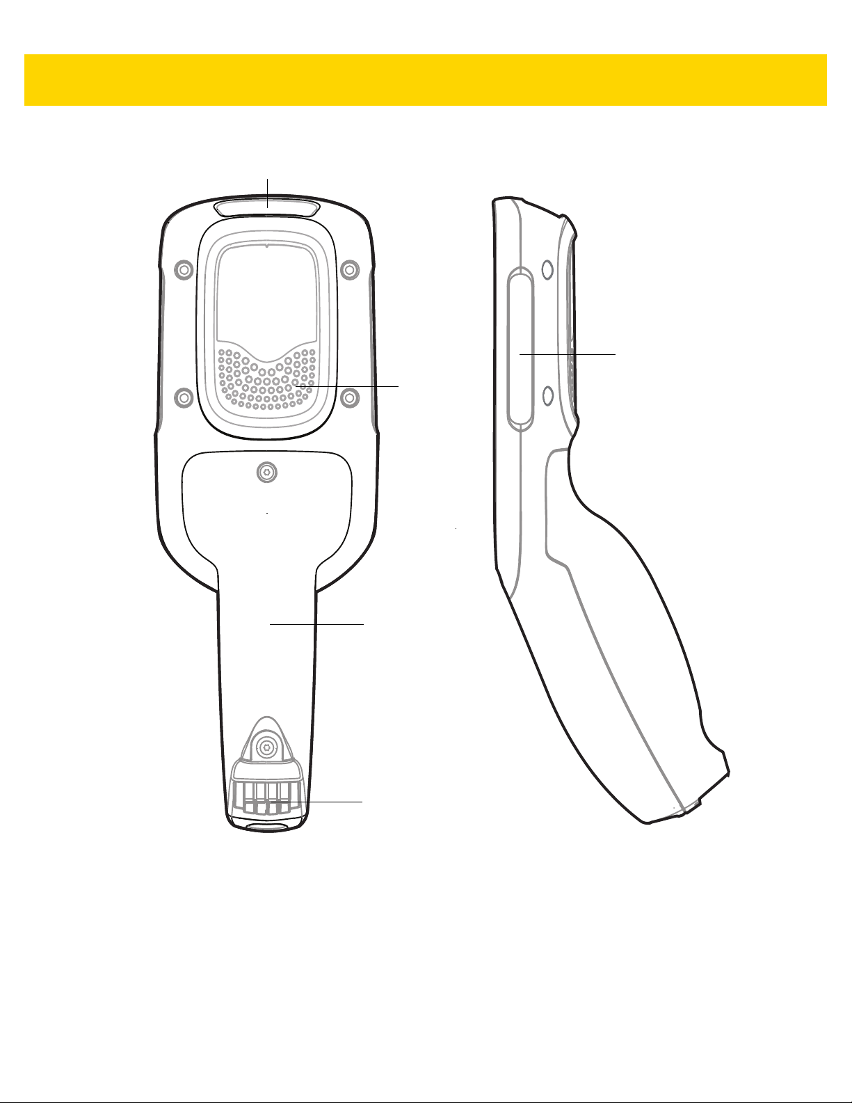
Battery Cover
Speaker
Power Connector
Scan Exit Window
Branding Plate Slot
Getting Started 1 - 3
Figure 1-2 Back View
Page 22

1 - 4 MC18 with Android OS Product Reference Guide
Accessories
Table 1-1 Accessories
Accessory Part Number Description
MC18 Lithium Ion Battery BTRY-MC18-27MAG-01 MC18 Lithium Ion Battery.
High Density (HD) Three Slot
Cradle (Locking).
High Density (HD) Three Slot
Cradle (Non-Locking)
Super High Density (SHD) Three
Slot Cradle (Locking)
Single Slot Cradle
BTRY-MC18-27MAG-10
CRD-MC18-3SLCKH-01
CRD-MC18-3SLOTH-01
CRD-MC18-3SLCKS-01
CRD-MC18-1SLOT-01
MC18 Lithium Ion Battery (
The cradle is used for docking up to three
MC18 units in HD installation configuration.
The cradle slots are equipped with a
mechanism that locks the MC18 units inside
the slots.
The Three Slot Cradle requires
PWRS-14000-241R), DC line cord and
unit (
country specific AC line cord (sold
separately).
The cradle is used for docking up to three
MC18 units in HD installation configuration.
Requires
(
PWRS-14000-241R), DC line cord and
country specific AC line cord (sold
separately).
The cradle is used for docking up to three
MC18 units in SHD installation configuration.
The cradle slots are equipped with a
mechanism that locks the MC18 units inside
the slots. Requires power supply unit
(PWRS-14000-241R), DC line cord and
country specific AC line cord (sold separately).
The cradle is used for docking a single MC18.
Requires power supply unit
(PWRS-14000-241R), DC line cord and
country specific AC line cord (sold separately).
power supply unit
QTY-10
power supply
).
Release Key KT-MC18-CKEY-20 Tool used to mechanically unlock the MC18
from the Three Slot Cradle and the Single
Slot Cradle (QTY-20).
MC18 Terminal Reboot Tool KT-MC18-REBOOT-05 Tool used to perform cold boot of the MC18
(QTY-5).
Cradle Cover Removal T ool KT-MC18-CTOOL-01 Tool used for removing the Three Slot Cradle
cover.
Deployment Kit KT-MC18-CSTKIT-01 Includes:
• 20-pack of Release Key
(KT-MC18-CKEY-20)
• 5-pack of Terminal Reboot Tool
KT-MC18-REBOOT-05)
• One Three Slot Cradle Front Panel
Removal Tool (KT-MC18-CT OOL-01 )
Page 23

Getting Started 1 - 5
Table 1-1 Accessories (Continued)
Accessory Part Number Description
Single Slot Cradle Release Key PSS-3KY01-00R Key used to mechanically unlock the MC18
from a Single Slot Cradle (QTY-20)
.
Cart Holder Mounting Kit PSS-3SH01-00R Kit
Programming Cable CBL-MC18-USB1-01
Interconnection Cable 25-66431-01R
Cradle Interconnection Extension
Cable
Charging Cable CBL-MC18-Y2MET- 01 DC “Y” charging cable (
DC Charging Cable 25-66420-01R
DC “Y” Charging Cable Long 25-67592-01R
CBL-MC18-EXINT1-01
for mounting the MC18 on a shopping cart.
USB communication cable for connecting the
MC18 to a host computer.
An extension cable (12.6 Inch / 32 centimeter)
for connecting the Three Slot Cradle to
charging cable that is connected to
supply unit (PWRS-14000-241R).
An Interconnection extension cable (12.6 Inch
/ 32 centimeter) for connecting Three Slot
Cradle.
centimeter) for connecting cradles to power
supply unit (PWRS-14000-241R).
DC charging cable (19.5 Inch / 49.5
centimeter) used to connect a power supply
unit (PWRS-14000-241R) to one Single Slot
Cradle.
DC “Y” charging cable (39.7 Inch / 1 meter).
Connects a power supply unit
(PWRS-14000-241R) to two separate Three
Slot Cradles.
DC “Y”
power
19.5 Inch / 49.5
DC “Y” Charging Cable Short 25-66210-01R
Power Supply Unit
AC Line Cord
AC Line Cord
AC Line Cord
AC Line Cord
AC Line Cord
PWRS-14000-241R
23844-00-00R
50-16000-221R
50-16000-671R
50-16000-217R
50-16000-218R
DC “Y” charging cable (19.5 Inch / 1 meter).
Connects a power supply unit
(PWRS-14000-241R) to two separate Three
Slot Cradles.
100-240VAC, 12VDC, 9A. Requires country
specific AC line cord and DC cable (sold
separately).
AC Line Cord, 7.5 feet long, grounded, three
wire for power supplies. Associated Country:
United States
AC Line Cord, 1.8 meter, meter grounded,
three wire, USA NEMA 5-15P. Associated
Country: United States
AC Line Cord, 1.8 meter , grounded, three wire,
CIE 23-16 plug. Associated Country: Italy.
AC Line Cord, 1.9 meter , grounded, three wire,
AS 3112 plug. Associated Countries:
Australia, New Guinea
AC Line Cord, 1.8 meter , grounded, three wire,
NEMA 1-15P plug. Associated Country:
Japan.
Page 24

1 - 6 MC18 with Android OS Product Reference Guide
Table 1-1 Accessories (Continued)
Accessory Part Number Description
AC Line Cord
AC Line Cord
AC Line Cord
AC Line Cord
AC Line Cord
AC Line Cord
50-16000-219R
50-16000-220R
50-16000-257R
50-16000-669R
50-16000-672R
50-16000-678R
AC Line Cord, 1.8 meter , grounded three wire,
BS1363 plug. Associated countries: Hong
Kong, Iraq, Malaysia, Singapore, United
Kingdom.
AC Line Cord, 1.8 meter , grounded three wire
CEE 7/7plug. Associated countries: Europe,
Abu Dhabi, Bolivia, Dubai, Egypt, Iran, Russia,
Vietnam.
AC Line Cord, 1.8 meter , grounded three wire,
IEC 60320 C13 plug. Associated Country:
China.
1.9 meter grounded three wire, BS 546 Plug.
Associated country: India.
1.9 meter grounded three wire, S132 Plug.
Associated country: Israel.
36 inch grounded three wire.
Associated country: United States
Page 25
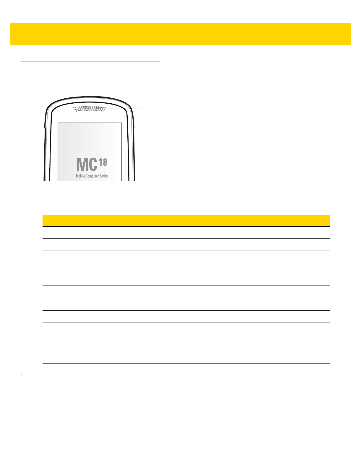
Status LED
Status LED
The Status LED indicates imaging and charging status. Table 1-2 describes the Status LED indications.
Figure 1-3 MC18 Status LED
Getting Started 1 - 7
Table 1-2 Status LED Indications
LED State Indication
Imaging
Off Normal operation or MC18 is turned off.
Red Imaging in progress (Scan key is pressed).
Single Green blink Successful decode.
Charging (MC18 docked in cradle)
Off Power not applied to cradle.
MC18 not inserted properly.
Charging LED feature disabled. See Charging the Battery on page 1-10.
Blinking green Charging.
Solid green Charging complete.
Blinking red Charging error, e.g.:
• Temperature is too low or too high.
• Charging has gone on too long without completion (typically eight hours).
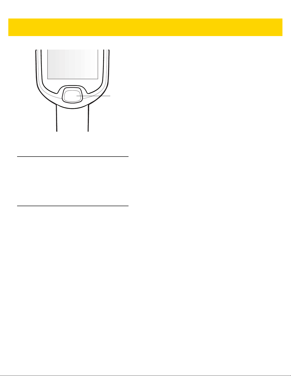
Scan Key
The Scan key operates the imager when a scanning application is active. When the MC18 is turned off, pressing
the Scan key to power on the MC18.
Page 26
1 - 8 MC18 with Android OS Product Reference Guide
Scan Key
Figure 1-4 Scan Key
Getting Started
To start using the MC18 for the first time:
• Install the battery
• Charge the battery.
Installing the Battery
To install the battery:
1. Remove tape securing battery cover to handle.
2. Lift the battery cover from the handle.
3. Guide and press the battery cable connector into th e fe male connector inside the battery compartment. The
connector is designed to only fit one way.
4. Place the battery inside the battery compartment.
5. Place the battery cover onto the handle.
6. Remove the two Torx screws from the provided plastic bag, inside the shipping box.
7. Secure the battery cover with the two Torx screws using a T8 Torx drive. Torque the screws to 3.6 Kgf-cm (3.1
in-lb).
Page 27

Getting Started 1 - 9
Battery Cover
Battery
Battery
Compartment
Battery Cable Connector
Figure 1-5 Installing the Battery
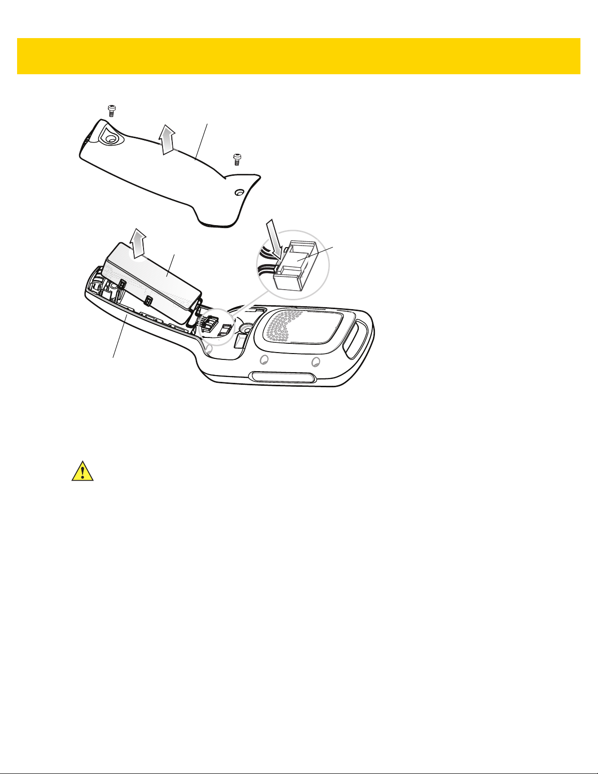
Removing the Battery
To remove the battery:
1. Touch and hold the soft power button until the menu appears.
2. Touch Power off.
3. Touch OK.
CAUTION The MC18 must be off before removing the battery. Failing to turn off the MC18 before removing the
battery may damage the data stored on flash memory or corrupt the operating system files.
4. Use T8 Torx drive to remove the two screws that secure the battery cover.
5. Lift the battery cover from the handle.
6. Inside the battery compartment, press down the plastic tab of the Battery cable conn ector and slide it out of the
female connector.
7. Remove the battery from the battery compartment.
Page 28
1 - 10 MC18 with Android OS Product Reference Guide
Battery Cover
Battery
Battery Compartment
Battery Cable Connector
Press down plastic tab to release
Figure 1-6 Removing the Battery
Charging the Battery
CAUTION Ensure that you follow the guidelines for battery safety described in Battery Safety Guidelines on page
12-1.
Before using the MC18 for the first time, charge the battery. The battery fully charge s in approximately four hours.
To charge the battery:
1. Ensure the cradle is connected to the appropriate power source. See Chapter 6, Cradle Installation for more
information.
2. Dock the MC18 in a cradle. The MC18 starts to charge automatically.
Page 29
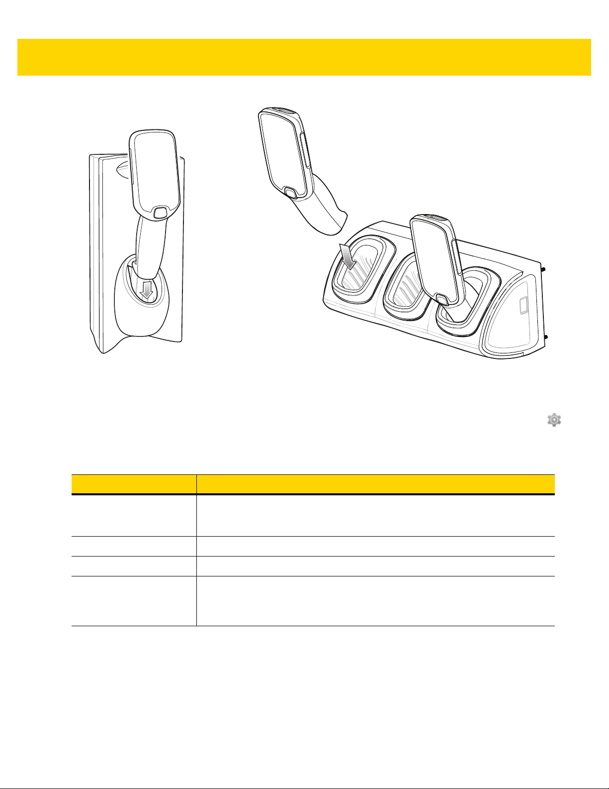
Getting Started 1 - 11
Three Slot CradleSingle Slot Cradle
Figure 1-7 Docking MC18 into Cradle
By default the Charging LED indication is disabled. Th e user can en able the Charging LED indica tion. Touch >
Charging indicator. Touch Enable Charging indicator checkbox.
Table 1-3 Charging Status LED Indications
LED State Indication
Off Power not applied to cradle.
MC18 not inserted properly.
Charging LED feature disabled.
Blinking green Charging.
Solid green Charging complete.
Blinking red Charging error, e.g.:
• Temperature is too low or too high.
• Charging has gone on too long without completion (typically eight hours).
Page 30

1 - 12 MC18 with Android OS Product Reference Guide
Starting the MC18
The MC18 starts automatically as soon as power is applied; either with a charged battery installed or when inse rted
into the cradle.
If charged battery is installed and the MC18 is turned off, press the Scan key to turn on.
When the MC18 is powered on for the first time, it initializes its system. The splash screen appears for a short
period of time.
Figure 1-8 Splash Screen
The splash screen is followed by the boot animation screen and then the Home Screen.
Figure 1-9 Home Screen
Powering On
To power on the MC18, press and release the Scan key.
Page 31

Manual Release of MC18 from Cradles
Release Key
The MC18 cradles contain a locking mechanism that locks the MC18 inside the cradle when docked. The MC18
releases from the cradle when a software command is received from the system. If the MC18 fails to un-lock during
normal operation, use a release key to un-lock the MC18.
Software Release
To remove the MC18 from the cradle:
1. Touch and hold the soft power button until the menu appears.
2. Touch Cradle unlock. The cradle unlocks the MC18.
3. Remove the MC18 from the cradle.
Manual Release of MC18 from the Single Slot Cradle
NOTE The MC18 also can be unlocked from the cradle by software command using the Cradle Utility (see
Cradle Utility on page 4-13).
Getting Started 1 - 13
To release a locked MC18 from a Single Slot Cradle:
1. Insert the release key into the slot located at the bottom side of the cradle.
2. While pressing the release key all the way into the slot, remove the MC18 from the cradle.
Figure 1-10 Manual Release of MC18 from a Single Slot Cradle
Manual Release of MC18 from the Three Slot Cradle
NOTE The cradle includes models that do not have a locking mechanism. T o identify the model of cradle, refer to
Table 1-1 on page 1-4.
NOTE The MC18 also can be released by software command using the Cradle Utility application (see Cradle
Utility on page 4-13) or customer developed application using Zebra Android EMDK.
To release a locked MC18 from a Three Slot Cradle:
Page 32

1 - 14 MC18 with Android OS Product Reference Guide
Release Key
1. Insert the release key straight into the slot, to a point where the bend stops.
2. Hold the release key pressed inside the slot and remove the MC18 from the slot.
Figure 1-11 Manual Release of MC18 from a Three Slot Cradle
Battery Management
To check the charge status of the main battery, on the Home screen touch > > About device > Battery
Information.
Battery status indicates that the battery is discharging (not charging ) and Battery level lists the battery charge (as
a percentage of fully charged).
Monitor Battery Usage
The Battery screen lists which applications consume the most ba ttery power. Also use it to turn off app lications that
were downloaded if they are consuming too much power.
Touch > > Battery.
Figure 1-12 Battery Screen
Page 33

Getting Started 1 - 15
The Battery screen lists the applications using the battery. The discharge graph at the top of the screen shows the
rate of the battery discharge since last charged (short periods of time when connected to a charger are shown as
thin green lines at the bottom of the chart), and how long it has been running on battery powe r.
Touch an application in the Battery screen to display details about its power consumption. Different applications
display different information. Some applications inclu d e buttons that open screens with settings to adjust power
use.
Low Battery Notification
When the battery charge level drops below 15%, the MC18 displays a notice to connect the MC18 to power. Place
the MC18 into a cradle to charge the battery.
Figure 1-13 Low Battery Notification
When the battery charge drops below 10%, the MC18 displays a notice to connect the MC18 to power. The user
must charge the battery using one of the charging accessories.
When the battery charge drops below 5%, the MC18 turns off.
Place the MC18 into a cradle to charge the battery.
Battery Optimization
Observe the following battery saving tips:
• Set the screen to turn off after a short period of non-use. See Setting Screen Timeout Setting on page 1-17.
• Reduce screen brightness. See Setting the Screen Brightness on page 1-17.
• Turn off all wireless radios when not in use.
• Turn off automatic syncing for Email, Calendar, Contacts and other applications.
• Use the Power Control widget to check and control the status of radios, the screen brightness, and syncing.
• Minimize use of applications that keep the MC18 from suspending, for example, music and video
applications.
Battery Diagnostics
The Diagnostic App displays battery status information. This information can also be retrieved programmatically
using the Zebra Android EMDK.
To view the results of the diagnostics test touch > .
Page 34

1 - 16 MC18 with Android OS Product Reference Guide
Figure 1-14 Diagnostic App Screen
• Battery Health - Indicates the health of the battery.
• State of Charge - Indicates the current charge level of the battery.
• Time to Battery Empty - Indicates the amount of time (in minutes) before the device goes into critical
suspend mode.The device goes to suspend depending on the display timeout setting. However, the device
goes to critical suspend when the battery charge level is at 5%.
• Battery Manufacture Date - Displays the battery manufacturer date (YYYY-MM-DD).
• Minutes Since device last reboot - Indicates how long ago (in minutes) the device was rebooted.
• Battery has been charging for - Indicates the amount of time (in minutes) that the device has been
charging during the current charge cycle.
• Days since battery was last replaced - Indicates the number since the battery was replaced in the device.
Turning Off the Radios
To turn off all the radios:
NOTE Alternately, you can place the device into Airplane mode using the Quick Settings option.
1. Press the soft power button until the menu appears.
2. Touch Airplane mode. The airplane icon appears in the Status bar indicating that all the radios are off.
Setting the Date and Time
The date and time is automatically synchronized using a NIT Z serv er when th e MC 18 is conn ec te d to a cellular
network. The user is only required to set the time zone or set the date and time when not connected to a cellular
network.
1. Touch > .
2. Touch Date & time.
Page 35

3. Touch Automatic date & time to disable automatic date and time synchronization.
4. Touch Set date.
5. Scroll up and down to select the month, date and year.
6. Touch OK.
7. Touch Set time.
8. Select the hour, minutes and part of the day.
9. Touch OK.
10. Touch Select time zone.
11. Select the current time zone from the list.
12. Touch .
Display Setting
Use Display settings to change the screen brightness, change the background image, set sleep time, change the
screen saver, and change font size.
Getting Started 1 - 17
Setting the Screen Brightness
To set the screen brightness:
1. Touch > .
2. Touch Display.
3. Touch Brightness.
Figure 1-15 Brightness Dialog Box
4. In the Brightness dialog box, use the slider to set a brightness level.
5. Touch .
Setting Screen Timeout Setting
To set the screen sleep time:
1. Touch > .
2. Touch Display.
3. Touch Sleep.
4. Select one of the sleep values.
• 15 seconds
• 30 seconds
• 1 minute
Page 36

1 - 18 MC18 with Android OS Product Reference Guide
• 2 minutes
• 5 minutes
• 10 minutes
• 30 minutes
• Never (default).
5. Touch .
Setting Font Size
To set the size of the font is system applications:
1. Touch > .
2. Touch Display.
3. Touch Font size.
4. Select one of the font size values.
• Small
• Normal (default)
• Large
• Huge.
5. Touch .
Page 37

General Sound Setting
Use the Sound & notification settings to configure volume and notification.
On the Home screen, touch > > Sound & Notification.
Getting Started 1 - 19
Figure 1-16 Sound & Notification Screen
Sound
Use the sound settings to change the volume of media, alarms and notifications.
• Media Volume - Controls the music and media volume.
• Alarm Volume - Controls the alarm clock volume.
• Notification Volume - Controls the ringtone and notification volume.
Page 38

1 - 20 MC18 with Android OS Product Reference Guide
Figure 1-17 Sound & Notification Screen
• Interruptions
• When calls and notifications arrive - Touch to select when calls and notifications arrive.
• Priority Interruptions
• Events and reminders - Touch to allow events and reminders notifications to come through.
• Calls - Touch to silence all calls.
• Messages - Touch to allow message notifications to come through.
• Calls/messages from - Touch to choose which types of contacts can come through.
• Downtime
• Days - Touch to cho ose whic h da ys pr ior ity int er ru pt ion s ett ing s ar e en ab le d.
• Start time - Touch to choose a start time when priority interruption settings are enabled.
• End time - Touch to choose an end time when priority interruption settings are disabled.
• Interruptions allowed - Touch to choose if priority interruptions are allow or no interruptions are
allowed.
• Default notification ringtone- Touch to select a sound to play for all system notifications.
• Other sounds
• Screen locking sounds - Check to play a sound when locking and unlocking the screen (default –
disabled).
• Touch sounds - Check to play a sound when making screen selections (default – enabled).
Page 39

Notification
Use the notification settings to configure how notifications arrive and which notification arrive.
On the Home screen, touch > > Sound & Notification.
• When device is locked - Manage whether notifications can be seen when the MC18 is locked.
• App notifications - Modify the notificati on settings individually for an application. The setting under When
device is locked always takes precedence over the setting for an individual application.
• Notification access - Displays which applications can access notifications.
When a notification arrives, its icon appears at the top of the screen. Icons for pending notifica tions appear
on the left, and system icons on the right.
Getting Started 1 - 21
Page 40

1 - 22 MC18 with Android OS Product Reference Guide
Resetting the MC18
There are five reset functions:
• Soft reset
• Hard reset
• Enterprise reset
• Factory reset
• Full Factory reset.
Performing a Soft Reset
Perform a soft reset if applications stop responding.
1. Press and hold the soft power button until the menu appears.
2. Touch Reset.
3. The device reboots.
Performing a Hard Reset
CAUTION Perform a hard reset only if the MC18 stops responding.
When in a Cradle
To perform a hard reset when the MC18 is docked inside the cradle:
NOTE Ensure power is applied to the cradle.
1. Press and hold the Scan key for 10 seconds until the display powers off.
2. Release of the Scan key.
3. Briefly press and release the Scan key, the MC18 reboots.
When Out of the Cradle
To perform a hard reset when the MC18 is out of the cradle:
1. Insert the terminal reboot tool into the MC18 power connector.
Page 41

Getting Started 1 - 23
Terminal Reboot Tool
Scan Key
Power Connector
Figure 1-18 Terminal Reboot Tool
2. Press and hold the Scan key for 10 seconds until the display powers off.
3. Release of the Scan key.
4. Remove the terminal reboot tool.
Briefly press and release the Scan key, the MC18 reboots.
Performing an Enterprise Reset
An Enterprise Reset erases all data in the /cache and /data partitions and clears all de vice settings, except those in
the /enterprise partition.
Before performing an Enterprise Reset, copy all applications and the key remap configuration file that you want to
persist after the reset into the
1. Download the Enterprise Reset file from the Support Central web site.
2. Copy the Enterprise Reset zip file to the root of the Internal Storage. See Chapter 7, USB Communication.
3. Remove the Programming cable from the device.
4. Press and hold the soft power button until the menu appears.
5. Touch Power Off.
6. Touch OK.
7. Press and hold the Scan key.
8. When the System Recovery screen appears, relea s e the bu tton.
/enterprise/usr/persist folder.
Page 42

1 - 24 MC18 with Android OS Product Reference Guide
Figure 1-19 System Recovery Screen
9. Tap the display until apply update from On Device Storage is highlighted.
10. Press the Scan key.
11. Tap the display until Enterprise Reset zip file is highlighted.
12. Press the Scan key. The Enterprise Reset occurs and then the device resets.
Performing a Factory Reset
A Factory Reset erases all data in the /cache, /data and /enterprise partitions in internal storage and clears all
device settings. A Factory Reset returns the device to the last installed operating system image. To revert to a
previous operating system version, re-install that operating system image. See MC18 System Update on page 138
for more information.
1. Download the Enterprise Reset file from the Support Central web site.
2. Copy the Factory Reset zip file to the root of On Device Storage or the root of Internal Storage. See Chapter 7,
USB Communication.
3. Remove the Programming cable from the device.
4. Press and hold the soft power button until the menu appears.
5. Touch Power Off.
6. Touch OK.
7. Press and hold the Scan key.
8. When the System Recovery screen appears, relea s e the bu tton.
Page 43

Figure 1-20 System Recovery Screen
9. Tap the display until apply update from On Device Storage is highlighted.
10. Press the Scan key.
11. Tap the display until the Factory Reset zip file is highlighted.
12. Press the Scan key. The Factory Reset occurs and then the device resets.
Getting Started 1 - 25
Page 44

1 - 26 MC18 with Android OS Product Reference Guide
Page 45

CHAPTER 2 USING THE MC18
1
2
34675
8
9
Introduction
This chapter describes the screens, status and notification icons, and controls on the MC18, and provides basic
instructions for using the MC18.
Home Screen
The Home screen displays when the MC18 turns on. Depending upon the configuration, the Home screen might
appear different. Contact your system administrator for more information.
After a suspend or screen time-out, the Home screen displays with the lock sliders. Slide to the right toward to
unlock the screen. For screen locking information see Un-Locking the Screen on page 2- 12.
Figure 2-1 Home Screen
Page 46

2 - 2 MC18 with Android OS Product Reference Guide
Notification Icons Status Icons
NOTE The Home screen icons can be configured by the user and may look different than shown.
The Home screen consists of the following:
Table 2-1 Home Screen Items
Item Description
1 — Status Bar Displays the time, status icons (right side), and notification icons (left side). For
more information see Status Icons on page 2-3 and Managing Notifications on
page 2-5.
2 — Browser Icon Opens the Browser application.
3 — Power Icon Places the MC18 in suspend mode when touched and opens menu when touched
and held.
4 — Menu Icon Displays running applications.
5 — All Apps Icon Opens the APPS window.
6 — Home Icon Displays the Home screen.
7 — Back Icon Displays the previous screen.
8 — Settings Icon Opens the Settings window.
9 — Shortcut Icons Opens applications installed on the MC18. See Application Shortcuts and Widgets
on page 2-6 for more information.
10 — Widgets Launches stand-alone applications that run on the Home screen. See Application
Shortcuts and Widgets on page 2-6 for more information.
The Home screen provides four additional screen s for placem ent of widgets and shortcuts. Swipe the screen left or
right to view the additional screens.
Status Bar
The Status bar displays the time, notification icons (left side ) and stat us ico ns (right sid e) .
Figure 2-2 Notification and Status Icons
If there are more notifications than can fit in the Status bar, displays indicating that more notifications exist.
Open the Notifications panel to view all notifications and status.
Page 47

Status Icons
Table 2-2 Status Icons
Icon Description
Indicates that the Alarm is active.
Indicates that the ringer is silenced.
Indicates that the battery is fully charged.
Indicates that the battery is partially drained.
Indicates that the battery charge is low.
Using the MC18 2 - 3
Indicates that the battery charge is very low.
Indicates that the battery is charging.
Indicates that the Airplane Mode is active. All radios are turned off.
Indicates that Bluetooth is on.
Connected to a Wi-Fi network.
No Wi-Fi signal.
Page 48

2 - 4 MC18 with Android OS Product Reference Guide
Notification Icons
Table 2-3 Notification Icons
Icon Description
Indicates that more notifications are available for viewing.
Indicates that data is syncing.
Indicates an upcoming event.
Indicates that an open Wi-Fi network is available.
Indicates that a song is playing.
Indicates that a problem with sign-in or sync has occurred.
Indicates that the MC18 is uploading data.
Indicates that the MC18 is downloading data when animated and download is complete when
static.
Indicates that the MC18 is connected via USB cable.
Indicates that the MC18 is connected to or disconnected from virtual private network (VPN).
Preparing Internal Storage.
Indicates that USB debugging is enabled on the MC18.
Indicates that the MultiUser feature is enabled. Appears only when MultiUser Administrator
application is installed.
Page 49

Using the MC18 2 - 5
Table 2-3 Notification Icons
Icon Description
Indicates that a new user is logging in. App ears only when MultiUse r Administrator application is
installed.
Indicates that the RxLogger application is running and capturing data.
Managing Notifications
Notification icons report the arrival of new messages, calendar events, and alarms, as well as ongoing events.
When a notification occurs, an icon appears in the Status bar with a brief description. See Notification Icons on
page 2-4 for a list of possible notification icons and their description. Open the Notifications pa nel to view a list of all
the notifications.
To open the Notification panel, drag the Status bar down from the top of the screen.
Figure 2-3 Notification Panel
To respond to a notification, open the Notifications Panel and then touch a notification. The Notifications Panel
closes and the subsequent activity is dependent on the notification.
To clear all notifications, open the Notifications Panel and then touch . All event-based notifications are
removed. Ongoing notifications remain in the list.
To close the Notification Panel, swipe the Notifications Panel up or touch .
Quick Settings
Use Quick Settings to get to frequently used settings, like turning on airplane mode . To open Quick Settings, swipe
down from the top of the screen with two fingers or twice with one finger.
Page 50

2 - 6 MC18 with Android OS Product Reference Guide
Figure 2-4 Quick Settings
To change a setting, just touch the icon:
• Display brightness: Slide to lower or increase the brightness of the screen.
• Wi-Fi network: Turn Wi-Fi on or off. To open Wi-Fi settings, touch the Wi-Fi network name.
• Bluetooth settings: Turn Bluetooth on or off. To open Bluetooth settings, touch the Bluetooth.
• Airplane mode: Turn airplane mode on or off. Airplane mode means device will not connect to Wi-Fi or
Bluetooth.
To close the Quick Settings Panel, swipe the Quick Settings Panel up or touch .
Application Shortcuts and Widgets
Application shortcuts placed on the Home screen allow quick and easy access to applications. Widgets are
self-contained applications placed on the Home screen to access frequently used features.
Adding an Application or Widget to the Home Screen
1. Go to the desired Home screen.
2. Touch .
3. Swipe right, if necessary, to find the application icon or widget.
4. Touch and hold the icon or widget until the Home screen appears.
5. Position the icon on the screen and then release.
Moving Items on the Home Screen
1. Touch and hold the item until it floats on the screen.
2. Drag the item to a new location. Pause at the edge of the screen to drag the item onto an adjacent Home
screen.
3. Lift finger to place the item on the Home screen.
Removing an App or Widget from the Home Screen
1. Go to the desired Home screen.
2. Touch and hold the application shortcut or widget icon until it floats on the screen.
Page 51

Using the MC18 2 - 7
3. Drag the icon to on the top of the screen and then release.
Folders
Use Folders to organize similar applications together. Tap the folder to open and display items in the folder.
Creating a Folder
To create a folder, there must be at least two app icons on the Home screen.
1. Go to the desired Home screen.
2. Touch and hold on one application icon.
3. Drag the icon and stack on top of another icon.
4. Lift and release.
Naming Folders
1. Touch the folder.
Figure 2-5 Open Folder
2. Touch the title area and enter a folder name using the keyboard .
3. Touch Done.
4. Touch anywhere on the Home screen to close the folder. The folder name appears under the folder.
Figure 2-6 Renamed Folder
Removing a Folder
1. Touch and hold the folder icon until it enlarges.
2. Drag the icon to and release.
Home Screen Wallpaper
Changing the Home Screen Wallpaper
NOTE Use of Live Wallpaper may reduce battery life.
1. Touch and hold the desktop until the menu appears.
Page 52

2 - 8 MC18 with Android OS Product Reference Guide
2. From the Choose wallpaper from menu, touch Gallery, Live wallpapers or Wallpapers.
•Gallery - Select to use an image stored on the device.
• Live wallpapers - Select to use an animated wallpaper image.
• Wallpapers - Select to use a wallpaper image.
3. Touch Set wallpaper.
Using the Touchscreen
Use the multi-tap sensitive screen to operate the device.
•Tap-Tap to:
• select items on the screen
• type letters and symbols using the on-screen keyboard
• press on-screen buttons.
• Tap and Hold - Tap and ho ld :
• an item on the Home screen to move it to a new location or to the trash.
• an item in Apps to create a shortcut on the Home screen.
• the Home screen to open a menu for customizing the Home screen.
• an empty area on the Home screen until the menu appears.
•Drag - Tap and hold an item for a moment and then move finger on the screen until reaching the new
position.
•Swipe - Move finger up and down or left and right on the screen to:
• unlock the screen
• view additional Home screens
• view additional application icons in the Launcher window
• view more information on an application’s screen.
• Double-tap - Tap twice on a web page, map, or other screen to zoom in and out.
•Pinch - In some applications, zoom in and out by placing two fingers on the screen and pinching them
together (to zoom out) or spreading them apart (to zoom in).
Using the On-screen Keyboard
Use the on-screen keyboard to enter text in a text field. To configure the keyboard settings, touch and hold ,
(comma) >
/ (forward slash) and then select Android keyboard settings.
Editing Text
Edit entered text and use menu commands to cut, copy, and paste text within or across applications. Some
applications do not support editing some or all of the text they display; others may offer their own way to select text.
Entering Numbers, Symbols and Special Characters
To enter numbers and symbols:
• Touch and hold one of the top-row keys until a menu appears then select a number. Keys with alternate
characters display an ellipsis ( ... ) below the character.
Page 53

Using the MC18 2 - 9
• Touch and hold the Shift key with one finger, touch one or more capital letters or symbols to enter them, and
then lift both fingers to return to the lowercase keyboa rd .
• Touch
• Touch the
To enter special characters, touch and hold a number or symbol key to open a menu of additional symbols.
• A larger version of the key displays briefly over the keyboard.
• Keys with alternate characters display an ellipsis ( ... ) below the character.
Applications
The APPS screen displays icons for all installed applications. The table below lists the applications installed on the
MC18. Refer to the MC18 Integrator Guide for information on installing and uninstalling application.
Table 2-4
Icon Description
?123 to switch to the numbers and symbols keyboard.
=\< key on the numbers and symbols keyboard to view additional symbols.
App Gallery - Provides links to utilities and demonstration applications that can be installed on
the MC18.
Battery Manager
level.
- Displays battery information, including charge level, status, health and wear
Browser - Use to access the Internet or intranet.
Calculator - Provides the basic and scientific arithmetic functions.
Calendar - Use to manage events and appointments.
Clock - Use to schedule alarms for appointments or as a wake-up.
Contacts - Use to manage contact information.
Cradle Firmware Update - Use to update cradle firmware..
Cradle Utility - Use to control cradle functionality.
Page 54

2 - 10 MC18 with Android OS Product Reference Guide
Table 2-4
Icon Description
DataWedge - Enables data capture using the imager.
Diagnostic App - Provides information about battery health.
Downloads - Lists all downloads files.
DWDemo - Provides a way to demonstrate the data capture features using the imager. See
DataWedge Demonstration on page 4-9 for more information.
elemez - Use to provide diagnostic information. See Elemez on page 4-11 for more
information.
Email - Use to send and receive email.
File Browser - Organize and manage files on the MC18. See File Browser on page 4-2 for
more information.
Gallery - Use to view photos stored on the device. For more information, se e Ga ller y on pag e
4-4 for more information.
Mobi Control Stage – Opens the Mobi Control Stage application to stage the device.
MSP Agent - Enables management of the MC18 from an MDM server. Requires the purchase
of an appropriate MDM client license per device to suit the level of management functionality
required.
Music - Play music stored on the device.
Rapid Deployment- Allows the MC18 to stage a device for initial use by initiating the
deployment of settings, firmware and software. Requires the purchase of an MDM client
license per device.
RxLogger - Use to diagnose device and application issues. See the MC18 Integrator Guide
for more information.
Search - Use the Google search engine to search the Internet and the MC18.
Settings - Use to configure the MC18.
Page 55

Table 2-4
Icon Description
StageNow - Allows the MC18 to stage a device for initial use by initiating the deployment of
settings, firmware and software.
AppLock Administrator - Use to configure the Application Lock feature. This icon appears
after the optional application is installed.
MultiUser Administrator - Use to configure the MultiUser feature. T his icon appea rs after the
optional application is installed.
Accessing Applications
All applications installed on the device are accessed using the APPS window.
1. On the Home screen, touch .
Using the MC18 2 - 11
Figure 2-7 APPS Window
2. Slide the APPS window left or right to view more application icons. Touch an icon to open the application.
NOTE See Application Shortcuts and Widgets on page 2-6 for information on creating a shortcut on the Home
screen.
Switching Between Recent Applications
1. Touch . A window appears on the screen with icons of recently used applications.
Page 56

2 - 12 MC18 with Android OS Product Reference Guide
Figure 2-8 Recently Used Applications
2. Slide the window up and down to view all recently used applications.
3. Swipe left or right to remove application from the list and force close the application.
4. Touch an icon to open it or touch to return to the current screen.
Un-Locking the Screen
Use the Lock screen to protect access to data on the MC18. Some email account require locking the screen. See
Chapter 11, Settings for information on setting up the locking feature. The Locking feature functions differently in
Single User mode or Multiple User mode.
Single User Mode
When locked, a pattern, PIN or password is required to unlock the device. Press the Power button to lock the
screen. The device also locks after a pre-defined time-out.
Press and release the Power button to wake the device.
The Lock screen displays. Slide up to unlock the screen.
If the Pattern screen unlock feature is enabled, the Pattern screen appears instead of the Lock screen.
If the PIN or Password screen unlock feature is enabled, enter the PIN or password after unlocking the screen.
Page 57

Figure 2-9 Lock Screen
Using the MC18 2 - 13
Figure 2-10 PIN Screen
Page 58

2 - 14 MC18 with Android OS Product Reference Guide
Figure 2-11 Pattern Screen
Figure 2-12 Password Screen
MultiUser Mode
With MultiUser login, multiple users can log on to the device with each user having access to various applications
and features. When enabled, the Login screen appears after powerin g on, rese tting or after the device wakes from
suspend mode.
MultiUser Login
1. In the User Name text field, enter the username.
Page 59

Figure 2-13 Multiple User Log In Screen
2. In the Password text field, enter the password.
3. Touch OK. After a resume from suspend, the user must enter the password.
Using the MC18 2 - 15
MultiUser Logout
1. Drag the Status Bar down from the top of the screen.
2. Touch MultiUser is active.
3. Touch Logout.
4. The Login screen appears.
Suspend Mode
The MC18 goes into suspend mode when the user presses the Power button or after a period of inactivity (set in
the Display settings window).
To wake the MC18 from Suspend mode, press the Power button.Alternately, press the Scan or Programmable
button to wake the device.
The Lock screen displays. Slide up to unlock the screen. If the Pattern screen unlock feature is enabled, the
Pattern screen appears instead of the Lock screen. See Un-Locking the Screen on page 2-12.
NOTE If the user enters the PIN, password or pattern incorrectly five times, they must wait 30 seconds before
trying again.
If the user forgets the PIN, password or pattern contact the system administrator.
Page 60

2 - 16 MC18 with Android OS Product Reference Guide
Lock Screen
Page 61

CHAPTER 3 WIRELESS
Wireless Local Area Networks
Wireless local area networks (WLANs) allow the MC18 to communicate wirelessly inside a building. Before using
the MC18 on a WLAN, the facility must be set up with the required hardware to run the WLAN (sometimes known
as infrastructure). The infrastructure and the MC18 must both be properly configured to enable this
communication.
Refer to the documentation provided with the infrastructure (access points (APs), access ports, switches, Radius
servers, etc.) for instructions on how to set up the infrastructure.
Once the infrastructure is set up to enforce the chosen WLAN security scheme, use the Wireless & networks
settings to configure the MC18 to match the security scheme.
The MC18 supports the following WLAN security options:
• Open
• Wireless Equivalent Privacy (WEP).
• Wi-Fi Protected Access (WPA/WPA2) Personal (PSK).
• Extensible Authentication Protocol (EAP).
• Protected Extensible Authentication Protocol (PEAP) - with MSCHAPV2 and GTC authentication.
• Transport Layer Security (TLS)
• TTLS - with Password Authentication Protocol (PAP), MSCHAP and MSCHAPv2 authentication.
• LEAP
• EAP-FAST - with MSCHAPV2 and GTC authentication.
The Status bar displays icons that indicate Wi-Fi network availability and Wi-Fi status. See Status Bar on page 2-2
for more information.
NOTE Turn off Wi-Fi when not using it, to extend the life of the battery.
Scan and Connect to a Wi-Fi Network
1. Touch .
Page 62

3 - 2 MC18 with Android OS Product Reference Guide
Figure 3-1 Settings Screen
2. Touch Wi-Fi.
3. Slide the Wi-Fi switch to the ON position. The MC18 searches for WLANs in the area and lists them.
Figure 3-2 Wi-Fi Screen
4. Scroll through the list and select the desired WLAN network.
5. For open networks, touch profile once or press and hold and then select Connect to network or for secure
networks enter the required password or other credentials then touch Connect. See the system administrator
for more information.
6. The MC18 obtains a network address and other required information from the ne twor k using the d ynamic host
configuration protocol (DHCP) protocol. To configure the MC18 with a fixed internet protocol (IP) address, See
Configuring the Device to Use a Static IP Address on page 3-6.
7. In the Wi-Fi setting field, Connected appears indicating that the MC18 is connected to the WL AN.
Page 63

Wireless 3 - 3
Configuring a Wi-Fi Network
To set up a Wi-Fi network:
1. Touch .
2. Touch Wi-Fi.
3. Slide the switch to the ON position.
4. The device searches for WLANs in the area and lists them on the screen.
5. Scroll through the list and select the desired WLAN network.
6. To uch the desired network. If the network security is Open, the device automatically connects to the network.
For all other network security a dialog box appears.
Figure 3-3 WLAN Network Security Dialog Box
7. If the network security is WEP or WPA/WPS2 PSK, enter the required password and then touch Connect.
Figure 3-4 802.1x EAP Security Dialog Box
8. If the network security is 802.1x EAP:
• Touch the EAP method drop-down list and select PEAP, TLS, TTLS, LEAP or FAST.
• Touch the Phase 2 authentication drop-down list and select an authentication method.
Page 64

3 - 4 MC18 with Android OS Product Reference Guide
• If required, touch CA certificate and select a Certification Authority (CA) certificate. Note: Certificates are
installed using the Security settings.
• If required, touch User certificate and select a user certificate. Note: User certificates are installed using
the Location & security settings.
• If required, in the Identity text box, enter the username creden tia ls.
• If desired, in the Anonymous identity text box, enter an anonymous identity username.
• If required, in the Password text box, enter the password for then given identity.
NOTE By default, the network Proxy is set to None and the IP settings is set to DHCP. See Configuring for a
Proxy Server on page 3-5 for setting connection to a proxy server and see Configuring the Device to Use
a Static IP Address on page 3-6 for setting the device to use a static IP address.
9. Touch Connect.
10. Touch .
Manually Adding a Wi-Fi Network
Manually add a Wi-Fi network if the network does not broadcast its name (SSID) or to add a Wi-Fi network when
out of range.
1. Touch .
2. Touch Wi-Fi.
3. Slide the Wi-Fi switch to the On position.
4. Touch > Add Network.
5. In the Network name text box, enter the name of the Wi-Fi network.
6. In the Security drop-down list, select the type of security. Options:
• None
•WEP
• WPA/WPA2 PSK
• 802.1x EAP.
7. If the network security is None, touch Save.
8. If the network security is WEP or WPA/WPA2 PSK, enter the required password and then touch Save.
9. If the network security is 802.1x EAP:
• Touch the EAP method drop-down list and select PEAP, TLS, TTLS, LEAP or FAST.
• Touch the Phase 2 authentication drop-down list and select an authentication method.
• If required, touch CA certificate and select a Certification Authority (CA) certificate. Note: Certificates are
installed using the Security settings.
• If required, touch User certificate and select a user certificate. Note: User certificates are installed using
the Security settings.
• If required, in the Identity text box, enter the username creden tia ls.
• If desired, in the Anonymous identity text box, enter an anonymous identity username.
• If required, in the Password text box, enter the password for then given identity.
Page 65

Wireless 3 - 5
By default, the network Proxy is set to None and the IP settings is set to DHCP. See Configuring for a
Proxy Server on page 3-5 for setting connection to a proxy server and see Configuring the Device to
Use a Static IP Address on page 3-6 for setting the device to use a static IP address.
1. Touch Save. To connect to the saved network, touch the saved network and select Connect.
2. Touch .
Configuring for a Proxy Server
A proxy server is a server that acts as an intermediary for requests from clients seeking resources from other
servers. A client connects to the proxy server, requesting some service, such as a file, connection, web page, or
other resource, available from a different server. The proxy server evaluates the request according to its filtering
rules. For example, it may filter traffic by IP address or protocol. If the request is validated by the filter, the proxy
provides the resource by connecting to the relevant server and requesting the service on behalf of the client.
It is important for enterprise customers to be ab le to set up secu re computing environm ents within their companies,
and proxy configuration is an essential part of doing that. Proxy configuration acts as a security barrier ensuring
that the proxy server monitors all traffic between the Internet and the intranet. This is normally an integral part of
security enforcement in corporate firewalls within intranets.
1. In the Wi-Fi list, touch a network.
2. Touch Advanced options checkbox.
3. Touch Proxy and select Manual.
Figure 3-5 Proxy Settings
4. In the Proxy hostname text box, enter the address of the proxy server.
5. In the Proxy port text box, enter the port number for the proxy server.
6. In the Bypass proxy for text box, enter addresses for web sites that do not require to go through the proxy
server. Use the separator “|” between addresses.
When entering proxy addresses the Bypass proxy for field, do not use spaces or carriage returns between
addresses.
7. Touch Connect.
8. Touch .
Page 66

3 - 6 MC18 with Android OS Product Reference Guide
Configuring the Device to Use a Static IP Address
By default, the device is configured to use Dynamic Host Configuration Protocol (DHCP) to assign an Internet
protocol (IP) address when connecting to a wireless network. To configure the device to connect to a network using
a static IP address:
1. In the Wi-Fi list, touch a network.
2. Touch Advanced options checkbox.
3. Touch IP settings and select Static.
Figure 3-6 Static IP Settings
4. In the IP address text box, enter an IP address for the device.
5. If required, in the Gateway text box, enter a gateway address for the device.
6. If required, in the Network prefix length text box, enter a the prefix length.
7. If required, in the DNS 1 text box, enter a Domain Name System (DNS) address.
8. If required, in the DNS 2 text box, enter a DNS address.
9. Touch Connect.
10. Touch .
Advanced Wi-Fi Settings
NOTE Advanced Wi-Fi settings are for the device not for a specific wireless network.
Use the Advanced settings to configure additional Wi-Fi settings. From the Wi-Fi screen, touch > Advanced to
view the advanced settings.
• Network notification - When enabled, notifies the user when an open network is available.
• Scanning always available - Select to let Google’s location service and other applications scan for
networks, even when Wi-Fi is off. (default - disabled).
Page 67

Wireless 3 - 7
• Keep Wi-Fi on during sleep - Opens a menu to set whether and when the Wi-Fi radio turns off.
• Always On - The radio stays on when the device enters suspend mode (default).
• Only when plugged in - The radio stays on while the device is connected to external power.
• Never On - The radio turns off when the device enters suspend mode (default).
• Wi-Fi frequency band - Options: Automatic (default), 5 GHz only or 2.4 GHz only.
• Install Certificates - Touch to install certificates.
• MAC address - Displays the Media Access Control (MAC) address of the device when connecting to Wi-Fi
networks.
• IP address - Displays the IP address of the device.
Additional Settings
Use the Additional Settings to configure additional Wi-Fi settings. Fro m the Wi-Fi screen, touch > Additional
Settings to view the additional settings.
• Regulatory
• Country selection - Displays the acquired country code if 802.1 1d is enabled else it displays the currently
selected country code.
• Region code - Displays the current region code.
• Band and Channel Selection
• Wi-Fi frequency band - Use to select the freque ncy band. Options: Auto (default), 5 GHz only or 2.4
GHz only.
• Available channels (2.4 GHz) - Use to select specific channels. Touch to display the Available channels
menu. Select specific channels. Touch OK.
• Available channels (5 GHz) - Use to select specific channels. Touch to display the Available channels
menu. Select specific channels. Touch OK.
• Logging
• Advanced Logging – Touch to enable advanced logging.
• Wireless logs - Use to capture Wi-Fi log files.
• Fusion Logger - Touch to open the Fusion Logger application. This application maintains a history of
high level WLAN events which helps to understand the status of connectivity.
Page 68

3 - 8 MC18 with Android OS Product Reference Guide
Figure 3-7 Fusion Logger Screen
• Fusion Status - Touch to display live status of WLAN state. Also provides information of device and
connected profile.
Figure 3-8 Fusion Status Screen
• About
•Version - Displays the current Fusion information.
Remove a Wi-Fi Network
To remove a remembered or connected network:
1. Touch .
2. Touch Wi-Fi.
3. In the Wi-Fi networks list, touch and hold the name of the network.
4. In the menu, touch Forget network.
5. Touch .
Page 69

Wi-Fi Advanced Features
Some additional Wi-Fi settings cannot be accesse d from the User Inte rface. They can be configured by using Wi-Fi
(CSP). Refer to EMDK documentation for the details on the Wi-Fi settings configuration using the Wi-Fi CSP.
• Auto Time Config - Using this feature, the device can sync up its time with Zebra WLAN infrastructure. This
feature works only when the device is connected to Zebra WLAN infrastructure and the feature is enabled on
the WLAN infrastructure side. Default: disabled.
• PMKID Caching - Allows the device to skip 802.1x authentication during roaming if it had previously
connected to that AP with a full 802.1x authentication. Default: disabled. Note: disable OKC when enabling
PMKID Caching.
• Opportunistic Key Caching - Use this feature to skip 802.1x authentication during roaming. The device will
go for full 802.1x authentication for the first time it connects to the network. For subsequent roaming, the
device skips 802.1x authentication. Default: enabled.
• Cisco Centralized Key Management - Allows the device to skip 802.1x and key-handshake phases during
roaming. This feature is available only when the device is connected to a Cisco infrastructure that supports
Cisco Centralized Key Management (CCKM). Default: enabled.
• Fast Transition - Fast T ransition (FT) is the fast roamin g standard, 8 02.11r. With this feature, the device can
skip 802.1x and key-handshake phases during roam. Default: enabled.
• Fast Transition Resource Information Container - Allows the device to request TSPEC as part of
reassociation frame exchange. This helps to avoid sending a separate resource request after roaming is
completed. Default: disabled.
•Power Save - The device can be configured to work in different power save modes:
i. Active - Keeps the WLAN radio always in active mode (i.e. power save mode disabled).
ii. Power save using WMM-PS - This is the default power save mode. Device uses WMM-PS power
save method if the AP is configured to use this. If the AP is not supporting WMM-PS, the device will
use PS-Poll power save method.
iii. Power save using PS-Poll - In this method, the device will use PS-Poll frames to retrieve buffered
frames from the AP.
iv. Null Data Power Save - In Null Data Power Save (NDP), the device will stay awake for 100 ms after
the last frame is sent or received. The device will send a Null Data packet with power management bit
cleared to retrieve buffered frames from the AP.
• 802.11k - Using 802.11k, the device can discover neighbor APs and adds support for different types of radio
resource measurements. Default: enabled.
• Band Preference - The device can b e configured to pre fer one band o ver another. By default, device prefers
5 GHz frequency band over 2.4 GHz.
• Subnet Roaming - When the device roams between different sub networks, if it detects that it is roaming to
a different subnet, the device will request a fresh IP address. Default: disabled.
Wireless 3 - 9
Zebra Mobility Extensions
Zebra Mobility Extensions make use 802.1 1 specifications and Zebra proprietary extensions to achieve the highest
level of performance, efficiency and reliability. The MC18 adds support for the following Zebra Mobility Extensions.
• Coverage Hole Detection - The MC18 includes enhancements to the IEEE 802.11k standard. These
improvements will report gaps in signal coverage to the Zebra wireless LAN infrastructure. Network
administrators can detect and mitigate coverage gaps present in the network for greater reliability. Default:
enabled.
Page 70

3 - 10 MC18 with Android OS Product Reference Guide
• • Aggregated Fast Transition - Aggregated FT improves on IEEE 802.11r, Over-the-DS fast roaming. In
conjunction with Zebra wireless LAN infrastructure, the MC18 will achieve more reliable and consistent fast
roaming. Default: enabled.
• • Scan Assist - The MC18 monitors neighbor access points and retrieves roaming related information from
the Zebra wireless LAN infrastructure without doing scans. Using this Scan Assist feature, the MC18
improves roaming. Default: enabled.
Bluetooth
Bluetooth-equipped devices can communicate without wires, using frequency-hopping spread spectrum (FHSS)
radio frequency (RF) to transmit and receive data in the 2.4 GHz Industry Scientific and Medical (ISM) band
(802.15.1). Bluetooth wireless technology is specifically designed for short-range (10 meters (32.8 feet) )
communication and low power consumption.
Devices with Bluetooth capabilities can exchange information (e.g., files, appointments, and tasks) with other
Bluetooth enabled devices such as printers, access points, and other mobile devices.
Adaptive Frequency Hopping
Adaptive Frequency Hopping (AFH) is a method of avoiding fixed frequency interferers, and can be used with
Bluetooth voice. All devices in the piconet (Bluetooth network) must be AFH-capable in order for AFH to work.
There is no AFH when connecting and discovering devices. Avoid making Bluetooth connections and discoveries
during critical 802.11b communications. AFH for Bluetooth consists of four main sections:
• Channel Classification - A method of detecting an interference on a channel-by-channel basis, or
pre-defined channel mask.
• Link Management - Coordinates and distributes the AFH information to the rest of the Bluetooth network.
• Hop Sequence Modification - Avoids interference by selectively reducing the number of hopping channels.
• Channel Maintenance - A method for periodically re-evaluating the channels.
When AFH is enabled, the Bluetooth radio “hops around” (instead of through) the 802. 11b high-rate channels. AFH
coexistence allows Enterprise devices to operate in any infrastructure.
The Bluetooth radio in this device operates as a Class 2 device power class. The maximum output power is 2.5
mW and the expected range is 10 meters (32.8 ft.). A de finition of rang es based on power class is difficult to obtain
due to power and device differences, and whether one measures open space or closed office space.
NOTE It is not recommended to perform Bluetooth wireless technology inquiry when high rate 802.11b operation
is required.
Security
The current Bluetooth specification defines security at the link level. Application-level security is not specified. This
allows application developers to define security mechanisms tailored to their specific need. Link-level security
occurs between devices, not users, while applic at ion -le vel security can be implemented on a per-user basis. The
Bluetooth specification defines security algorithms and procedure s required to auth enticate devices, and if needed,
encrypt the data flowing on the link between the device s. Device authentication is a mandatory feature o f Bluetooth
while link encryption is optional.
Pairing of Bluetooth devices is accomplished by creating an initialization key used to authenticate the devices and
create a link key for them. Entering a common personal identification number (PIN) in the devices being paired
Page 71

Wireless 3 - 11
generates the initialization key . T he PIN is never sent over the air. By default, the Bluetooth stack responds with no
key when a key is requested (it is up to user to respond to the key request event). Authentication of Bluetooth
devices is based-upon a challenge-response transaction. Bluetooth allows for a PIN or passkey used to create
other 128-bit keys used for security and encryption. The encryption key is derived from the link key used to
authenticate the pairing devices. Also worthy of note is the limited range and fast frequency hopping of the
Bluetooth radios that makes long-distance eavesdropping difficult.
Recommendations are:
• Perform pairing in a secure environment
• Keep PIN codes private and do not store the PIN codes in the device
• Implement application-level security.
Bluetooth Profiles
The device supports the following Bluetooth services:
• Service Discovery Protocol (SDP) - Handles the search for known and specific services as well as general
services.
• Serial Port Profile (SPP) - Allows use of RFCOMM protocol to emulate seri al cable connection between two
Bluetooth peer devices. For example, connecting the device to a printer.
• Generic Access Profile (GAP) - Controls connections in Bluetooth. Makes device visible and determines
how two devices communicate.
Bluetooth Power States
The Bluetooth radio is off by default.
• Suspend - When the MC18 goes into suspend mode, the Bluetooth radio stays on.
• Airplane Mode - When the MC18 is placed in Airplane Mode, the Bluetooth radio turns off. When Airplane
mode is disabled, the Bluetooth radio returns to the prior state. When in Airplane Mode, the Bluetooth radio
can be turned back on if desired.
Bluetooth Radio Power
Turn off th e Bluetooth radio to save po wer or if entering an area with radio r estrictions (e.g., a n airplane). When th e
radio is off, other Bluetooth devices cannot see or connect to the device. Turn on the Bluetooth radio to exchange
information with other Bluetooth devices (within range). Comm unicate only with Bluetooth radios in close proximity.
NOTE To achieve the best battery life turn off radios when not in use.
Enabling Bluetooth
1. Touch .
2. Touch Bluetooth.
3. Slide the Bluetooth switch to the ON position. also appears in the Status bar.
4. Touch .
Page 72

3 - 12 MC18 with Android OS Product Reference Guide
Disabling Bluetooth
1. Touch .
2. Touch Bluetooth.
3. Slide the Bluetooth switch to the OFF position.
4. Touch .
Discovering Bluetooth Device(s)
The MC18 can receive information from discovered devices without pairing. However, once paired, the MC18 and
a paired device exchange information automatica lly when the Bluetooth radio is on. To find Bluetooth devices in the
area:
1. Ensure that Bluetooth is enabled on both devices.
2. Ensure that the Bluetooth device to discover is in discoverable mode.
3. Ensure that the two devices are within 10 meters (32.8 feet) of one another.
4. Touch .
5. Touch Bluetooth.
The MC18 begins searching for discoverable Bluetooth devices in the area and displa ys them under Available
Devices.
6. Scroll through the list and select a device. The Bluetooth pairing request dialog box appears.
Figure 3-9 Bluetooth Pairing
7. Touch Pair on both devices.
8. The Bluetooth device is added to the Bluetooth devices list and a trusted ( “paired” ) connectio n is established.
Changing the Bluetooth Name
By default, the MC18 has a generic Bluetooth name that is visible to other devices when connected.
1. Touch .
2. Touch Bluetooth.
3. If Bluetooth is not on, slide the switch to the ON position.
4. Touch > Rename device.
5. Enter a name and touch Done.
6. Touch .
Page 73

Connecting to a Bluetooth Device
Once paired, connect to a Bluetooth device.
1. Touch .
2. Touch Bluetooth.
3. If Bluetooth is not on, slide the switch to the ON position.
4. In the Paired Devices list, touch an unconnected Bluetooth device.
When connected, the device is displayed as connected in the list.
Selecting Profiles on the Bluetooth Device
Some Bluetooth devices have multiple profiles. To select a profile:
1. Touch .
2. Touch Bluetooth.
3. In the Paired Devices list, touch next to the device name.
4. Under Use for, check or uncheck a profile to allow the device to use that profile.
Wireless 3 - 13
5. Touch .
Unpairing a Bluetooth Device
To unpair a Bluetooth device and erase all pairing information:
1. Touch .
2. Touch Bluetooth.
3. In the Paired Devices list, touch next to the device name.
4. Touch FORGET.
5. Touch .
Page 74

3 - 14 MC18 with Android OS Product Reference Guide
Page 75

CHAPTER 4 APPLICATIONS
Introduction
This chapter describes the applications installe d on the devi ce .
Battery Manager
The Battery Manager provides detailed information about the battery.
Figure 4-1 Battery Manager Screen
Battery level - Indicate the current battery charge level.
Time until empty - Indicates the amount of time befo re the batter y is depleted. Displays when the MC18 is n ot on
AC power.
Battery status
• Not charging - Indicates that the WT6000 is not connected to AC power.
• Charging over AC - Indicates tha t the WT6000 is connected to AC power and charging.
Page 76

4 - 2 MC18 with Android OS Product Reference Guide
1
2
3 4
5
Battery health - Indicates the health of the battery.
Wear level - Indicates the health of the battery in graphical form.
Advanced info - Tap to view additional battery information.
File Browser
Use the File Browser application to view and mange files on the device.
To open File Browser, touch > .
Figure 4-2 File Browser Screen
The address bar (1) indicates the current folder path. Touch the current folder path to manually enter a path and
folder name.
Use (2) to select multiple files/folder.
Use (3) to view the internal storage root folder.
Use (4) to view the Internal Storage root folder.
Use (5) to view the previous folder or to exit the application.
Touch and hold an item to perform an operation on that item. Select one of the options from the File Operations
menu:
• Information - View detailed information about the file or folder.
•Move- Move the file or folder to a new location.
• Copy - Copy the select file.
• Delete - Delete the selected file.
• Rename - Rename the select file.
• Open as - Open the selected file as a specific file type.
•Share- Share the file with other devices.
Page 77

To uch to open additional functionality:
• Touch > New Folder to create a new folder in the current folder.
• Touch > Search to search for a file or folder.
• Touch > Sort to sort the list by name, by type, by size or by date.
• Touch > Refresh to re-display the contents of the current folder.
• Touch > List View to change the folder view from tile to list format.
• Touch > Change Size to change the size of the icons: Large, Normal or Small.
• Touch > About File Browser to view the application version information.
Contacts
Use the Contacts application to manage contacts.
From a Home or Apps screen, touch . Contacts opens to the main list of contacts. View contacts in two ways at
the top of the screen: All Contacts and Favorites. Touc h the tabs to change how to view the contacts. Swipe up or
down to scroll through the lists.
Applications 4 - 3
Adding Contacts
1. In the Contacts application, touch .
2. If there are more than one account with contacts, touch the one to use.
3. Type the contact’s name and other information. Touch a field to start typing, and swipe down to view all
categories.
4. When information is entered into a field, an additional field is added for that category. For example, when a
home phone number is entered, a field to add a work phone number automatically displays. To open a menu
with preset labels, such as Home or Work for an email address, touch the label under the item of contact
information. To create a custom label choose Custom from the label drop-down menu.
5. Touch .
6. Touch .
Editing Contacts
1. In the Contacts application, touch a contact to edit.
2. Touch .
3. Edit the contact information.
4. Touch .
5. Touch .
Deleting Contacts
1. In the Contacts application, touch a person to edit.
Page 78

4 - 4 MC18 with Android OS Product Reference Guide
2. Touch .
3. Touch Delete.
4. Touch OK to confirm.
Gallery
NOTE The device supports the following image formats: jpeg, gif, png and bmp.
The device supports the following video formats: H.263, H.264 and MPEG4 Simple Profile.
Use Gallery to:
• view photos
• play videos
• perform basic editing of photos
• set photos as wallpaper
• set photos as a contact photo
• share photos and videos.
To open the Gallery application, touch > .
Gallery presents all photos and videos stored in memory.
Figure 4-3 Gallery — Albums
• Touch an album to open it and view its contents. The photos and videos in the album are displayed in
chronological order.
• Touch a photo or video in an album to view it.
• Touch to return to the main Gallery screen.
Page 79

Applications 4 - 5
Working with Albums
Albums are groups of images and videos in folders. Touch an album to open it. The photos and videos are listed in
a chronologically ordered grid. The name of the album displa ys at the top of th e scr ee n .
Figure 4-4 Photos Inside an Album
Swipe left or right to scroll images across the screen.
Share an Album
1. Touch > .
2. Touch and hold an album until it highlights.
3. Touch other albums as required.
4. Touch . The Share menu opens. Touch the application to use to share the selected albums.
5. Follow the instructions within the selected application.
Get Album Information
1. Touch > .
2. Touch and hold an album until it highlights.
3. Touch .
4. Touch Details.
Deleting an Album
To delete an album and its contents:
1. Touch > .
2. Touch and hold an album until it highlights.
3. Check other albums to delete. Ensure that other albums are selected.
4. Touch .
Page 80

4 - 6 MC18 with Android OS Product Reference Guide
5. In the Delete selected item? menu, touch OK to delete the album.
Working with Photos
Use Gallery to view photos and edit and share photos.
Viewing and Browsing Photos
To view a photo:
1. Touch > .
2. Touch an album to open it.
3. Touch a photo.
Figure 4-5 Photo Example
4. Swipe left or right to view the next or previous photo in the album.
5. To uch the photo to view the controls.
6. Double-tap the screen to zoom in or pinch two fingers together or spread them apart to zoom in or out.
7. Drag the photo to view parts that are not in view.
Cropping a Photo
1. In Gallery, touch a photo to view the controls.
2. Touch .
3. Touch Crop. The white cropping tool appears.
4. Use the cropping tool to select the portion of the photo to crop.
• Drag from the inside of the cropping tool to move it.
• Drag an edge of the cropping tool to resize it to any proportion.
• Drag a corner of the cropping tool to resize it with fixed proportions.
Page 81

Figure 4-6 Cropping Tool
5. Touch SAVE to save a copy of the cropped photo. The original version is retained.
Applications 4 - 7
Setting a Photo as a Contact Icon
1. Touch > .
2. Touch an album to open it.
3. Touch the photo to open it.
4. Touch .
5. Touch Set picture as.
6. Touch Contact photo.
7. In the Contacts application, touch a contact.
8. Touch the white box and crop the photo accordingly.
9. Touch SAVE.
Share a Photo
1. Touch > .
2. Touch an album to open it.
3. Touch a photo to open it.
4. Touch .
5. Touch the application to use to share the selected photo. The application selected opens with the photo
attached to a new message.
Deleting a Photo
1. Touch > .
2. Touch an album to open it.
3. Touch a photo to open it.
Page 82

4 - 8 MC18 with Android OS Product Reference Guide
4. Touch .
5. Touch Delete.
6. In the Delete selected item? menu, touch OK to delete the photo.
Working with Videos
Use Gallery to view videos and share videos.
Watching Videos
1. Touch > .
2. Touch an album to open it.
3. Touch a video.
Figure 4-7 Video Example
4. Touch . The video begins to play.
5. Touch the screen to view the playback controls.
Sharing a Video
1. Touch > .
2. Touch an album to open it.
3. Touch a video to open it.
4. Touch . The Share menu appears.
5. Touch the application to use to share the selected video. The application selected opens with the video
attached to a new message.
Deleting a Video
1. Touch > .
2. Touch an album to open it.
Page 83

3. Touch a video to open it.
4. Touch .
5. Touch Delete.
6. Touch OK.
DataWedge Demonstration
Use DataWedge Demonstration to demonstrate data capture functionality.
Applications 4 - 9
Figure 4-8 DataWedge Demonstration Window
Table 4-1 DataWedge Demonstration Icons
Icon Description
Select to disable imager illumination.
Select to enable imager illumination.
Indicates that the data capture function is through the imager.
Select to enable picklist mode.
Select to enable normal scan mode.
Opens a menu to view the application information or to set the application DataW edge profile.
Page 84

4 - 10 MC18 with Android OS Product Reference Guide
NOTE See Chapter 9, DataWedge for information on DataWedge configuration.
Either press the Scan key or touch the yellow scan button in the application to enable data capture. The captured
data appears in the text field below the yellow button.
RxLogger
RxLogger is a comprehensive diagnostic tool that provides application and system metric s. It allows for custom
plug-ins to be created and work seamlessly with this tool. RxLogger is used to diagnose device and application
issues. Its information tracking includes the following: CPU load, memory load, memory snapshots, battery
consumption, power states, wireless logging, cellular logging, TCP dumps, Blueto oth logging, GPS logging, logcat,
FTP push/pull, ANR dumps, etc. All logs and files generated are saved onto flash storage on the device (internal or
external).
Figure 4-9 RxLogger
RxLogger Configuration
RxLogger is built with an extensible plug-in architecture and comes packaged with a number of plugins already
built-in. The included plug-ins are described below. Touch > Settings to open the configuration screen.
Configuration File
RxLogger configuration can be set using an XML file. The config.xml configuration file is located on the Enterprise
storage in the
Edit the configuration file and the replace the .XML file on the device. There is no need to stop and restart the
RxLogger service since the file change is automatically detected.
RxLogger\config folder . Copy the file from the device to a host computer using a USB connection.
Enabling Logging
1. Touch > .
2. Touch Start.
Page 85

3. Touch .
Disabling Logging
1. Touch > .
2. Touch Stop.
3. Touch .
Extracting Log Files
1. Connect the device to a host computer using an USB connection.
2. Using a file explorer, navigate to the On Device Storage in the /RxLogger folder.
3. Copy the file from the device to the host computer.
4. Disconnect the device from the host computer.
Elemez
Applications 4 - 11
NOTE Elemez collects specific device information in the background and sends this information to us to help
improve product functionality. This feature can be disabled. See Disabling Elemez Data Collection.
Ensure that the date, time and time zone are set correctly prior to using Elemez.
Use Elemez to provide diagnostics information to us. Touch Submit Diagnostics button to send the data.
Figure 4-10 Elemez Application
Disabling Elemez Data Collection
The user can disable the Elemez application from collection specific data in the background and sending it to Zebra
Technologies.
1. From the Home screen, touch > Apps.
Page 86

4 - 12 MC18 with Android OS Product Reference Guide
2. Swipe left or right until the ALL tab displays.
3. Scroll through the list and touch Elemez.
4. In the App info screen, touch Uninstall updates.
5. In the Uninstall updates dialog box, touch OK.
6. Touch OK.
7. After uninstall is complete, touch OK.
8. In the All tab, scroll through the list and touch Elemez.
9. Touch Disable.
10. In the Disable built-in app? dialog box, touch OK.
11. Touch .
Enabling Elemez Data Collection
The user can re-enable the Elemez application for collection specific data in the background and sending it to
Zebra Technologies.
1. From the Home screen, touch > Apps.
2. Swipe left or right until the ALL tab displays.
3. Scroll through the list and touch Elemez.
4. In the App info screen, touch Enable.
5. Touch .
6. Touch .
7. Touch .
8. Touch Enable Elemez.
Page 87

Cradle Utility
Use the Cradle Utility to:
• control of the cradle
• Set up the cradle
• Perform cradle diagnostics
• View cradle information.
To use the Cradle Utility:
1. Dock the MC18 inside the cradle.
2. Touch > .
NOTE The cradle ID and location information and charge settings are retained across firmware upgrades.
Controlling the Cradle
Applications 4 - 13
1. Tap the CRADLE UNLOCK tab to set the cradle unlock information.
Figure 4-11 Cradle Utility - Cradle Unlock Tab
• Unlock Period: The duration in seconds for which the MC18 remains in unlocked state (if not removed from
the cradle). For example; if unlock period is set to 15 and unlock signal is received, the MC18 will unlock and
lock back after 15 seconds (if its not removed by user).
• Unlock Cradle: Press Unlock Cradle to manually unlock the MC18 from the crad le.
•LED: Check the LED box to enable the cradle LED indication.
• Smooth Effect: Check the Smooth Effect box to enable smooth blinking of the LEDs.
• LED Setting > On: The duration (in ms) that the cradle LED is remains turned on or blinks during unlock.
• LED Setting > Off: The duration (in ms) that the cradle LED is remains turned off or blinks during unlock.
• LED Setting > Count: The number of times the cradle LED blinks when user presses the blink button.
•Blink: Tap to test the cradle LED operation.
Page 88

4 - 14 MC18 with Android OS Product Reference Guide
Setting the Cradle
Setting the cradle charging rate: Depending on the cradle installation configuration, the store technician can
configure each individual cradle slot to enable/disable fast charge. Each cradle can be configured to charge its
docked terminal at 1Ah (normal charging mode - default setting) or 1.5Ah (fast charging mode).
NOTE The cradle charging rate is retained across firmware upgrades.
1. Tap the Settings tab to set the cradle information.
Figure 4-12 Cradle Utility - Setting Tab
•Row ID: The cradle row number in the dispenser wall.
• Column ID: The cradle column number in the dispenser wall.
• Wall ID: The number of dispenser wall where the cradle is positioned.
•Read Data: Retrieve setting data from the cradle memory and display on the screen.
• Write Data: Tap this button to program the row/col/wall information onto the cra dle. Note that each slot on the
Three Slot Cradle needs to be programmed separately.
• Enable Fast Charge: Enable the cradle to charge the MC18 at a current of 1.5A (default setting is 1A)
• Reset Row: Tap to update the Row ID the text field to “0” on the application.
• Reset Column: Tap to update the Column ID the text field to “0” on the application.
• Reset Wall: Ta p to updat e the Wall ID the text field to “0” on the application.
Performing Cradle Diagnostics
1. Touch Diagnostic tab to perform the cradle diagnostics:
Page 89

Applications 4 - 15
Figure 4-13 Cradle Utility - Diagnostic Tab
• Cycle Reading: Check the Cycle Reading box to perform continues diagnostics and display the cradle
status information. During diagnostics, a progress bar is shown of the screen.
•Read Data: Tap to start performing diagnostics.
• Import Data: Tap to save the recorded results of the diagnostics on a file.
Viewing Cradle Information
1. Touch Info tab.
Figure 4-14 Cradle Utility - Info Tab
2. Touch Get Info to read the cradle information.
Page 90

4 - 16 MC18 with Android OS Product Reference Guide
Page 91

CHAPTER 5 DATA CAPTURE
Introduction
The MC18 imager allows collection of data by scanning bar codes.
The imager has the following features:
• Reads a variety of bar code symbologies, including the most popular linear, postal, and 2-D code types (see
Appendix A, Technical Specifications).
• Contains advanced intuitive aiming light for easy point-and-shoot operation.
Scanning Considerations
Typically, scanning is a simple matter of aim, scan/decode and a few quick trial efforts master it. However, two
important considerations can be used to optimize any scanning performance:
• Range
Any scanning device decodes well over a particular working range — minimum and maximum distances from
the bar code. This range varies according to bar code density and scanning device optics.
Scanning within range brings quick and constant decodes; scanning too close or too far away prevents
decodes. Move the MC18 closer and further away to find the right working range for the bar codes being
scanned. However, the situation is complicated by the availability of various integrated scanning modules. The
best way to specify the appropriate working range per bar code density is through a ch art called a decode zone
for each scan module. A decode zone simply plots working range as a function of minimum element widths of
bar code symbols.
• Angle
Don’t scan at too sharp an angle; the scanner needs to collect scattered reflections from the scan to make a
successful decode. Practice quickly shows what tolerances to work within.
NOTE Contact the Global Customer Support if chronic scanning difficulties develop. Decoding of properly printed
bar codes should be quick and effortless.
Page 92

5 - 2 MC18 with Android OS Product Reference Guide
Incorrect
Correct
Red Illumination Frame
Red Aiming Dot
Scanning Bar Codes
1. Open any application that can receive text.
2. Aim the scan exit window at the bar code.
3. Press the Scan key - the status LED illuminates red.
Ensure the red aiming dot is at the center of the bar code. Upon successful decode, the Status LED changes
from red to green and audible beep sounds if bar code was decoded successfully.
Figure 5-1 Imager Illumination Frame
4. Release the Scan key. The bar code data displays on the screen.
Figure 5-2 DataWedge Demo Screen
Scanning Tips
Optimal scanning distance varies with bar code density and scanner optics.
• Hold the scanner farther away for larger symbols.
• Move the scanner closer for symbols with bars that are close together.
NOTE Scanning procedures depend on the application and MC18 configuration. An application may use
different scanning procedures from the one listed above.
Page 93

DataWedge
DataWedge is a utility that adds advanced bar code scanning capability to any application without writing code. It
runs in the background and handles the interface to built-in bar code scanners. The captured bar code data is
converted to keystrokes and sent to the target application as if it was typed on the keypad.
Enabling DataWedge
To enable the DataWedge Application:
1. Touch > > .
2. Touch Settings.
3. Touch the DataWedge enabled checkbox. A blue checkmark appears in the checkbox indicating that
DataWedge is enabled.
4. Touch .
Disable DataWedge
Getting Started 5 - 3
To disable DataWedge:
1. Touch > > .
2. Touch Settings.
3. Touch the DataWedge enabled checkbox. The blue checkmark disappears from the checkbox indicating that
DataWedge is disabled.
4. Touch .
Page 94

5 - 4 MC18 with Android OS Product Reference Guide
Page 95

CHAPTER 6 CRADLE INSTALLATION
Introduction
A typical Personal Shopper system is comprised of a family of hardware devices interconnected through a WLAN
radio backbone to the retail establishment’s server(s). The hardware devices are the MC18 mobile computers,
single-slot or Three Slot Cradles, power supplies and cables. A dispenser typically refers to a piece of furniture
which has mounted to it the cradles, their power supplies, and cables.
Customers (retail establishments) design their own dispensers to meet their particular floor space and display
requirements. The information in this chapter should help a customer to design a dispenser and to understand the
installation requirements.
IMPORTANT The MC18 cradles are NOT compatible with MC17 cradles and the MC17 cradles are NOT
compatible with MC18 cradles.
Installation of the Single Slot Cradle
Installation of the Single Slot Cradle include the following mounting steps:
• Select the charging mode (see Charging Modes on page 6-1)
• Mount the Single Slot Cradles on a dispenser wall (see Mounting the Sing le Slot Cradle on a Dispenser W a ll
on page 6-2)
• Connect the wires to the cables (see Wiring on page 6-4)
• Set the cradle(s) (see Controlling the Cradle on page 4-13)
Charging Modes
Single Slot Cradles can be installed in the following charging modes:
• Standard charging
• Fast charging
There are some general charging conside ratio ns that must b e taken in to accoun t when desig ning a d ispen se r and
ordering hardware elements of a system:
Page 96

6 - 2 MC18 with Android OS Product Reference Guide
Alignment Holes
Standard Charging Mode
• In standard charging mode, no more than 12 cradles can be powered off of one power supply unit (p/n
PWRS-14000-241R) using “Y” power cable 25-67592-01R.
• In standard charging mode, the current draw by each docked MC18 can reach a maximu m of 1A.
Fast Charging Mode
• In fast charging mode, no more than six cradles can be powered off of one power supply unit (p/n
PWRS-14000-241R) using power cable 25-66420-01R.
• In fast charging mode, the current draw by each docked MC18 can reach a maximum of 1.5A.
Mounting the Single Slot Cradle on a Dispenser Wall
The cradle contains two mounting holes in the back housing so that it can be hanged on screws fixed to a
supporting furniture. In addition, it comes with plugs and a variety of cable routing outlets. Figure 6-3 provides the
necessary information about the location and dimensions of the mounting holes of the cradle.
To mount the Single Slot Cradle:
1. Loosen two captive screws securing the front cover to the base.
Figure 6-1 Remove Screws
2. Pull front cover away from base and then lift out of the base.
Figure 6-2 Cover Removal
Page 97

3. Use two screws to hang the cradle on a wall.
Two Mounting Holes
20.5 mm
(0.80”)
86 ± 0.2 mm
(3.39 ± 0.01”)
127 mm ± 0.4 mm
(5.0” ± 0.02”)
162.5 ± 0.2 mm
(6.39” ± 0.01”)
271.8 mm ± 0.7 mm
(10.70” ± 0.03”)
4mm
(0.16”)
8.5mm
(0.33”)
Cradle Installation 6 - 3
Figure 6-3 Hanging the Cradle on a Wall - Mounting Template
Page 98

6 - 4 MC18 with Android OS Product Reference Guide
Depth of cradle:
99 mm
(3.9”)
Figure 6-4 Overall Depth of Cradle
Wiring
NOTE During installation ensure all interconnect cables are fully enclosed within the po wer supply or cradle
enclosure.
1. Install power supply, including AC line cord and power cable, into Decorative Housing.
Page 99

Cradle Installation 6 - 5
Power Cable 25-66420-01R
Power Supply PWRS-14000-241R
(inside Decorative Housing)
Figure 6-5 Connecting Power Supply
2. Insert power cable through a cable outlet of cradle back housing.
3. Plug connector into power connector on printed circuit board.
4. If more than one cradle is being installed, connect the interconnect cable from the first cradle to the second
cradle.
Page 100

6 - 6 MC18 with Android OS Product Reference Guide
Interconnect Cable 25-66431-01R
Figure 6-6 Daisy-Chaining Cradles
5. Use plugs to cover un-used cable outlets.
Figure 6-7 Cable Hole Plug Installation
Assembly
1. Replace cover.
2. Secure cover with screws.
 Loading...