


York AC018X1222, AC024X1222, AC030X1222, AC036X1222, AC042X1221 Technical Manual
...
TECHNICAL
TECHNICAL
GUIDE
GUIDE
SPLIT-SYSTEM
AIR CONDITIONERS
12 SEER
MODELS:
AC018X12* THRU 060
(1.5 THRU 5 NOMINAL TONS, 1 PH)
ISO 9001
Certified Quality
Management System
LISTED
CERTIFICATIONAPPLIES ONLY
Due to continuous product improvement, specifications
are subject to change without notice.
Visit us on the web at www.york.com for the most
up-to-date technical information.
Additional rating information can be found at
www.ariprimenet.org.
O
T
A
R
D
I
E
I
A
F
S
I
T
R
C
E
O
C
M
A
P
I
R
R
-
L
C
E
O
Y
N
R
Y
D
R
I
U
A
T
T
T
I
I
N
U
E
C
E
R
T
I
F
I
A
C
A
R
I
S
WITH ARI.
O
N
I
N
G
R
T
Q
F
N
U
I
E
P
M
O
S
N
O
I
T
0
C
T
E
I
S
O
N
1
2
D
T
R
A
A
N
D
C
A
F
U
N
A
M
WHEN THECOMPLETE
SYSTEM ISLISTED
I
N
G
W
I
T
H
036-21106-005 Rev. B (0505)
DESCRIPTION
The 12 SEER Series condensing unit is the outdoor
part of a versatile system of air conditioning. It is
designed to be custom-matched with one of UPG’s
complete line of evaporator sections, each designed to
serve a specific function. Matching Air Handlers are
available for upflow, downflow or horizontal applications to provide a complete system. Electric Heaters
are available if required. Add-On coils are available for
use with upflow, downflow or horizontal furnaces and
air handlers.
WARRANTY
5-year limited parts warranty.
10-year limited compressor warranty.
FEATURES
• QUALITY CONDENSER COILS - The coil is constructed
of enhanced copper tube and aluminum fins.
• COIL PROTECTION - Coils are protected from damage by
a polymer mesh applied between the coil face, and a PVC
coated steel coil guard.
• PROTECTED COMPRESSOR - The compressor is internally protected against high pressure and temperature.
This is accomplished by the simultaneous operation of
high pressure relief valve and a temperature sensor which
protects the compressor if undesirable operating conditions occur. A liquid line filter-drier further protects the
compressor.
• DURABLE FINISH - The cabinet is made of pre-painted
steel. The pre-treated galvanized steel provides a better
paint to steel bond, which resists corrosion and rust creep.
Special primer formulas and matted textured champagne
finish insure less fading when exposed to sunlight.
• LOWER INSTALLED COST - Installation time and costs
are reduced by easy power and control wiring connections. Discharge line heat exchanger knockouts are provided, if required. Available in sweat connect models only.
The unit contains enough refrigerant for matching indoor
coils and 15 feet of interconnecting piping. The small base
dimension means less space is required on the ground or
roof.
• TOP DISCHARGE - The warm air from the top mounted
fan is blown up away from the structure and any landscaping. This allows compact location on multi-unit applications.
• LOW OPERATING SOUND LEVEL - The upward air flow
carries the normal operating noise up away from the livi ng
area. The rigid top panel effectively isolates any motor
sound. Isolator mounted compressor and the rippled fins
of the condenser coil muffle the normal fan motor and
compressor operating sounds.
• LOW MAINTENANCE - Long life permanently lubricated
motor-bearings need no annual servicing.
• EASY SERVICE ACCESS - Fully exposed refrigerant connections, a single panel covering the electrical controls
and the molex plug in the control box connecting the condenser fan, make for easy servicing of the unit.
• SECURED SERVICE VALVES - Secured re-usable ser-
vice valves are provided on both the liquid and vapor
sweat connections for ease of evacuating and charging.
• U.L. and C.U.L. listed - approved for outdoor application.
Certified in accordance with the Unitary Small Equipment certification program, which is based on ARI Standard 210/240.
FOR DISTRIBUTION USE ONLY - NOT TO BE USED AT POINT OF RETAIL SALE
036-21106-005 Rev. B (0505)
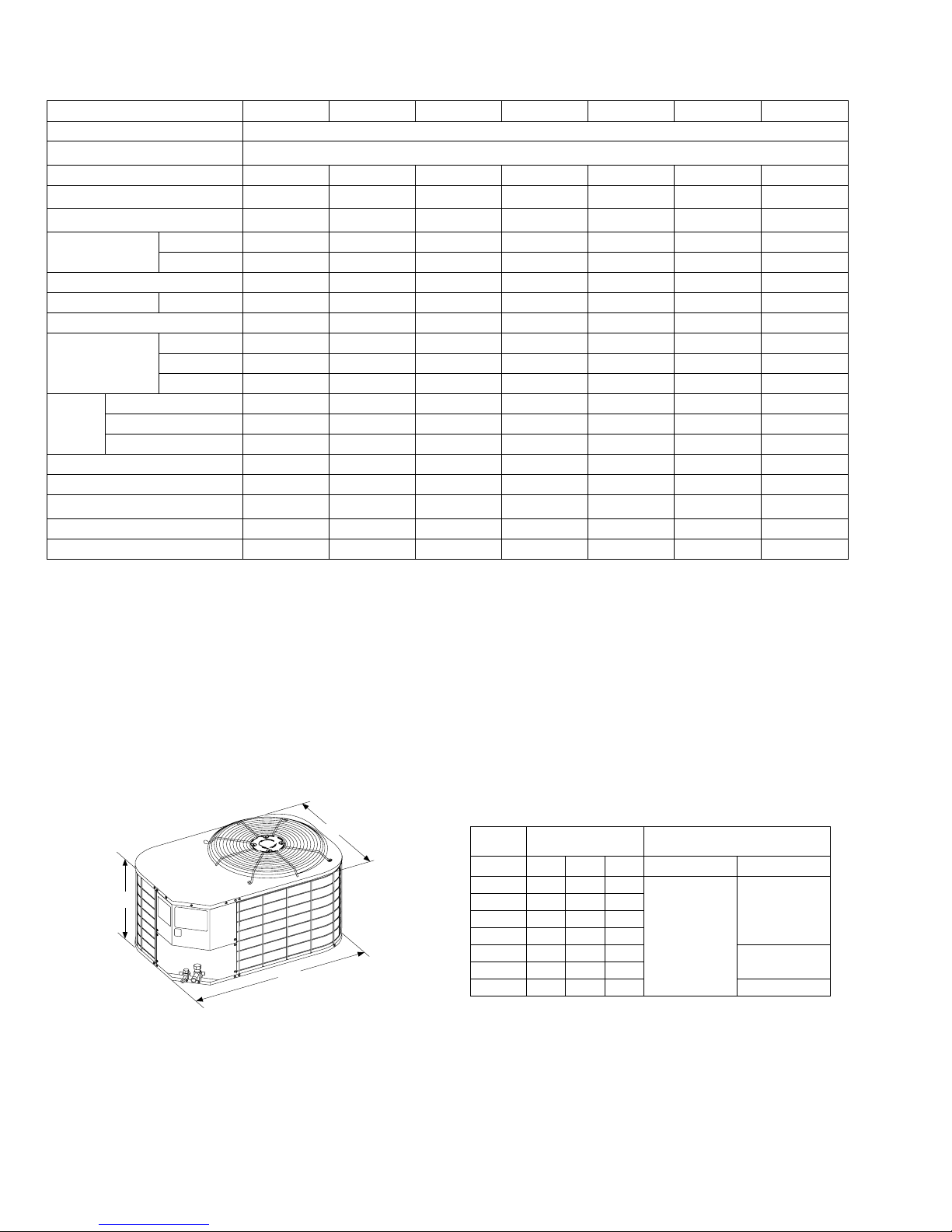
Physical and Electrical Data
MODEL AC018X1222 AC024X1222 AC030X1222 AC036X1222 AC042X1221 AC048X1222 AC060X1224
Unit Supply Voltage 208/230 – 1 – 60
Normal Voltage Range
1
Minimum Circuit Ampacity 10.1 14.1 16.5 19.7 26.2 28.5 37.5
Max. Overcurrent Device Amps
Compressor Type
Compressor Amps
3
Rated Load 7.7 10.9 12.8 14.7 19.9 21.8 28.8
Locked Rotor 48 60 68 82 115 105 145
2
15 25 25 30 45 50 60
Recip Inertia Recip Recip
Crankcase Heater No No No Yes No No No
Fan Motor Amps Rated Load 0.5 0.5 0.5 1.3 1.3 1.3 1.5
Fan Diameter Inches 18 18 22 22 22 22 22
Rated HP 1/12 1/12 1/15 1/4 1/4 1/4 1/4
Fan Motor
Nominal RPM 1,100 1,100 850 850 850 850 850
Nominal CFM 2,000 2,000 2,300 3,300 3,300 3,300 3,450
Face Area Sq. Ft. 12.58 12.58 15.72 15.72 17.03 19.65 23.58
Coil
Rows Deep 1 1 1 1 1 1 1
Fin / Inches 18 18 18 18 18 18 22
Liquid Line OD 3/8 3/8 3/8 3/8 3/8 3/8 3/8
Vapor Line OD 3/4 3/4 3/4 3/4 7/8 7/8 1-1/8
Unit Charge (Lbs. - Oz.)
4
4 - 9 4 - 7 5 - 8 5 - 3 6 - 13 7 - 7 8 - 15
Charge Per Foot, Oz. 0.68 0.68 0.68 0.68 0.70 0.70 0.76
Operating Weight Lbs. 144 146 156 161 157 190 198
1 Rated in accordance with ARI Standard 110, utilization range “A”.
2 Dual element fuses or HACR circuit breaker.
3 All scrolls listed with a superscript “B” are Bristol scrolls. All scrolls listed with a superscript “C” are Copeland scrolls.
4 The Unit Charge is correct for the outdoor unit, matched indoor coil and 15 feet of refrigerant tubing. For tubing lengths oth er than 15 feet, add or sub-
tract the amount of refrigerant, using the difference in length multiplied by the per foot value.
187 to 252
Scroll
B
Recip
Scroll
B
A
B
2 Unitary Products Group
All dimensions are in inches. They are subject to change without
notice. Certified dimensions will be provided upon request.
DIMENSIONS - 1 Phase
C
UNIT
MODEL
DIMENSIONS
(INCHES)
11
B C Liquid Vapor
A
REFRIGERANT CONNECTION
LINE SIZE
018 25 35 23
024 25 35 23
030 27 37 27
036 27 37 27
3/8””
042 29 37 27
048 33 37 27
060 39 37 27 7/8”*
1 Including Fan Guard.
* Expander fitting required for 1-1/8” line set.
3/4”
7/8”

036-21106-005 Rev. B (0505)
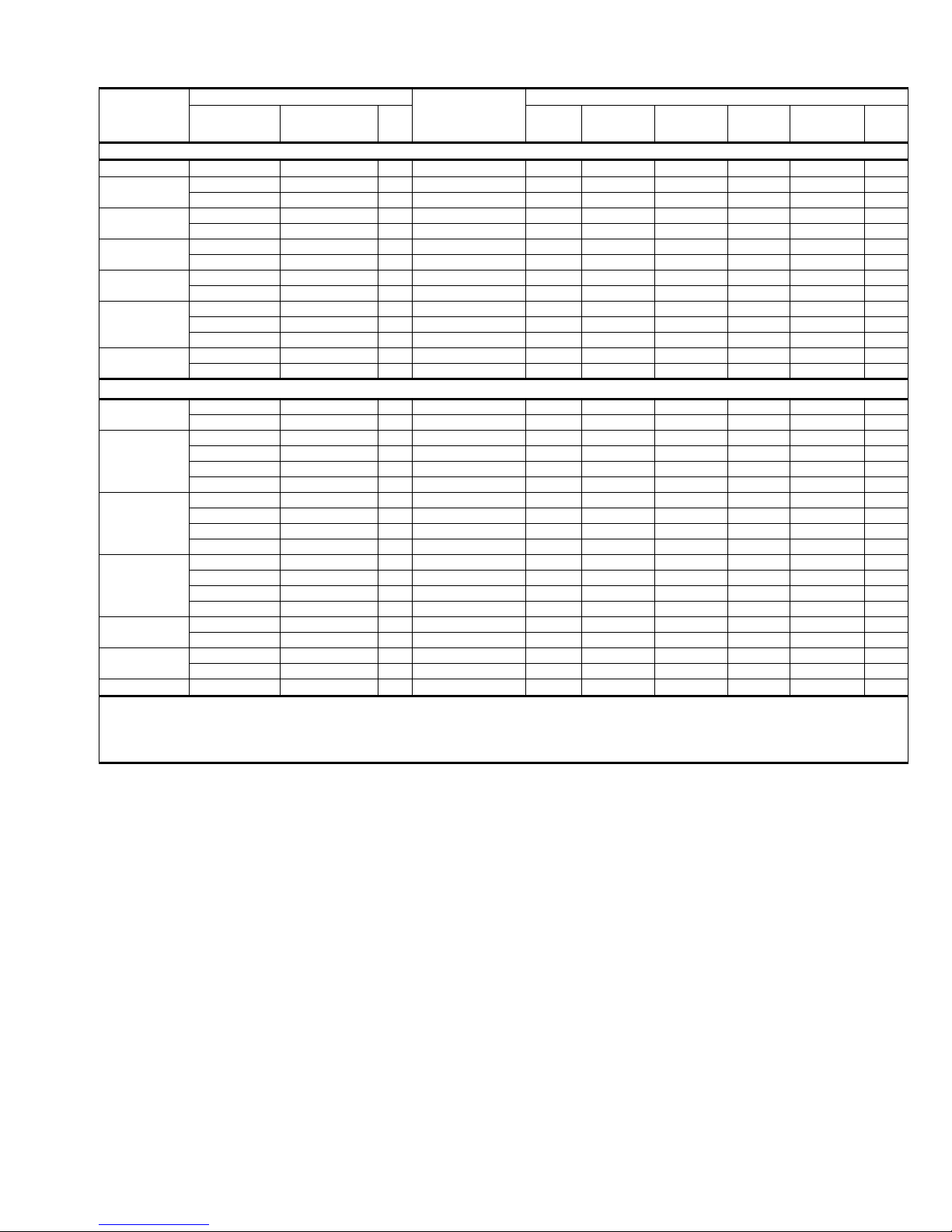
Additional R-22 Charge / Orifice Size for Various Match ed Systems - 1 Phase
Outdoor Unit AC018X1222 AC024X1222 AC030X1222 AC036X1222 AC042X1221 AC048X1222 AC060X1224
Unit Orifice (s)
Factory R-22 Charge, lbs-oz. 4 - 9 4 - 7 5 - 8 5 - 3 6 - 13 7 - 7 8 - 15
G2FD024(S,H)14,17(T) 61
G2FD030(S,H)17(T) 65
G2FD035(S,H)14(T) 65
G2FD036(S,H)17(T) 75
G2FD036(S,H)21(T) 75
G2FD042(S,H)21(T) 78
G2FD046(S,H)17(T) 78
G2FD048(S,H)21,24(T) 84
G2FD060(S,H)24(T) 90
G2FD061H24(T) 90
G1FA/G1UA024S14,17(T) 59
G1FA/G1UA030S14(T) 65
G1FA/G1UA036S14(T) 73
G1FA/G1UA036S17,21(T) 73
G1FA/G1UA048S17(T) 84
G1FA/G1UA048S21(T) 84
G1FA/G1UA060S21,24(T) 90
G1HA024H14 61 053 + 03 059 + 03 – – – – –
G1HA024H14(T) TXV 701 + 03 + 03 – – – – –
G1HA036H14 75 – 59 + 12 63 + 11 73 + 08 – – –
G1HA036H14(T) TXV 702 – – + 11 + 08 – – –
G1HA036H17 78 – – 63 + 14 73 + 12 – – –
G1HA036H17(T) TXV 702 – – + 14 + 12 – – –
G1HA048H21 84 – – – 73 + 09 78 + 07 87 + 08 –
G1HA048H21(T) TXV 703 – – – + 09 + 07 + 08 –
G1HA060H24 90 – – – – – 87 + 15 –
G1HA060H24(T) TXV 703 – – – – – + 15 703 + 5
G1NA030S17K 63
G1NA030S21M 78
1
Indoor Coil
Coil Orifice
G1HD024 59
G1HD036 69
G1HD048 81
G1HD060 93
53 59 63 73 78 87 –
4
Orifice or TXV Kit 2 - Additional Charge, Oz.
3
53 + 3 59 + 3 – – – – –
701 + 3 701 + 3 – – – – –
53 + 6 59 + 6 63 + 4 – – – –
701 + 6 701 + 6 701 + 4 – – – –
53 + 6 59 + 6 63 + 4 73 + 0 – – –
701 + 6 701 + 6 701 + 4 702 + 0 – – –
– 59 + 10 63 + 8 73 + 6 – – –
– 701 + 10 701 + 8 702 + 6 – – –
– – 63 + 11 73 + 8 – – –
– – 701 + 11 702 + 8 – – –
– – 63 + 14 73 + 12 78 + 0 – –
– – 701 + 14 702 + 12 702 + 0 – –
– – 63 + 16 73 + 12 78 + 0 87 + 0 –
– – 701 + 16 702 + 12 702 + 0 703 + 0 –
– – – 73 + 16 78 + 10 87 + 11 –
– – – 702 + 16 702 + 10 7 03 + 11 –
–––––87 + 15–
– – – – – 703 + 15 703 + 5
–––––87 + 19–
– – – – – 703 + 19 703 + 11
53 + 5 59 + 4 – – – – –
701 + 5 701 + 4 – – – – –
– 59 + 13 63 + 11 73 + 7 – – –
– 701 + 13 701 + 11 702 + 7 – – –
– – – 73 + 13 78 + 3 87 + 4 –
– – – 702 + 13 702 + 3 703 + 4 –
–––––87 + 12
– – – – – 703 + 12
53 + 0 59 + 0 – – – –
701 + 0 701 + 0 – – – 703 + 5
– 59 + 3 63 + 0 – – – –
– 701 + 3 701 + 0 – – – –
– 59 + 8 63 + 6 73 + 3 – – –
– 701 + 8 701 + 6 702 + 3 – – –
– 59 + 6 63 + 4 73 + 0 – – –
– 701 + 6 701 + 4 702 + 0 – – –
– – 63 + 16 73 + 13 78 + 0 87 + 0 –
– – 701 + 16 702 + 13 702 + 0 703 + 0 703 + 0
– – 63 + 18 73 + 9 78 + 7 87 + 8 –
– – 701 + 18 702 + 9 702 + 7 703 + 8 –
– – – – 78 + 16 87 + 15 –
– – – – 702 + 16 703 + 15 –
53 + 6 59 + 6 63 + 4 – – – –
701 + 6 701 + 6 701 + 4 – – – –
53 + 6 59 + 6 63 + 4 – – – –
701 + 6 701 + 6 701 + 4 – – – –
Unitary Products Group 3

036-21106-005 Rev. B (0505)
Additional R-22 Charge / Orifice Size for Various Matched Systems - 1 Phase (Continued)
Outdoor Unit AC018X1222 AC024X1222 AC030X1222 AC036X1222 AC042X1221 AC048X1222 AC060X1224
Unit Orifice (s)
Factory R-22 Charge, lbs-oz. 4 - 9 4 - 7 5 - 8 5 - 3 6 - 13 7 - 7 8 - 15
G1NA036S17L 63
G1NA048S21D 78
G1NA048S24P 63
G1NA060S24T 78
G1NF024SOF 63
G1NF036SOF 67
G1NF048SOF 78
G1NF060SOF 87
F2RP024N06(T) 61
F2RP030N06(T) 65
F2RP036N06(T) 75
F2RP042N06(T) 78
F2FP048N06(T) 84
F2FP060N06(T) 90
F2FV060N06(T) 90
FOOTNOTES:
1. These orifices are factory mounted in the flow control device of each indoor coil and must be removed for TXV installation.
2. A TXV kit must be used with these coils to obtain system performance. (701,702,703 indicates 1TV07 ...series).
3. Systems matched with furnaces or air handlers not equipped with blower-off delays, may require bl ower Time Delay Kit #6918A5011.
PROCEDURES:
1. Unit factory charge listed on the unit nameplate includes refrigerant for the condenser, the smallest evaporator and for 15 feet of
2. Verify the orifice size and additional charge required for specific evaporator coil in the system using the above table.
3. Additional charge for the amount of interconnecting line tubing greater than 15 feet at the rate specified in the table above.
4. Permanently mark the unit nameplate with the total system charge. Total System Charge = Base Charge (as shipped) + adder for
5. If the orifice in the evaporator was changed, verify the evaporator nameplate has been marked with the correct orifice size.
1
Indoor Coil
Coil Orifice
interconnecting line tubing.
evaporator + adder for line set.
53 59 63 73 78 87 –
4
Orifice or TXV Kit 2 - Additional Charge, Oz.
3
– – 63 + 15 73 + 12 – – –
– – 701 + 15 702 + 12 – – –
– – – 73 + 12 78 + 0 87 + 0 –
– – – 702 + 12 702 + 0 703 + 0 –
– – – 73 + 13 78 + 2 87 + 1 –
– – – 702 + 13 702 + 2 703 + 1 –
–––––––
––––––703 + 0
–––––––
–––––––
– 59 + 12 63 + 0 73 + 7 – – –
– 701 + 12 701 + 0 702 + 7 – – –
– – – – 78 + 21 87 + 6 –
– – – – 702 + 21 703 + 6 –
–––––87 + 18–
– – – – – 703 + 18 –
53 + 4 59 + 4 – – – – –
701 + 4 701 + 4 – – – – –
– 59 + 6 63 + 4 – – – –
– 701 + 6 701 + 4 – – – –
– – 63 + 4 73 + 8 – – –
– – 701 + 4 702 + 8 – – –
– – – 73 + 13 78 + 0 – –
– – – 702 + 13 702 + 0 – –
– – – 73 + 16 78 + 10 87 + 11 –
– – – 702 + 16 702 + 10 7 03 + 11 –
–––––87 + 15–
– – – – – 703 + 15
–––––87 + 15–
– – – – – 703 + 15 703 + 5
703
5
+ 5
4 Unitary Products Group
036-21106-005 Rev. B (0505)
COOLING CAPACITY - With Air Handler Coils
UNIT MODEL
MODEL
AIR HANDLER
ELECTRIC
HEAT KW
2
W
COIL
MODEL
1
RATED
CFM
TOTAL
CAPACITY
1 PH 12 SEER AC WITH N-AH / G2FD
AC018X1222
AC024X1222
AC030X1222
AC036X1222
AC042X1221
AC048X1222
AC060X1223
AC018X1222
AC024X1222
AC030X1222
AC036X1222
AC042X1221
AC048X1222
AC060X1223
Rated in accordance with DOE test procedures (Federal Register 12-27-79 and 3-18-88) and ARI Standards 210.
Cooling MBH based on 80°F entering air temperature, 50% RH, and rated air flo w.
EER (Energy Efficiency Ratio) is the total cooling output in BTU’s at a 95°F outdoor ambient divided by the total electric power in watt-hours at those conditions.
SEER (Seasonal Energy Efficiency Ratio) is th e tot al cooling out put in BTU’ s during a normal ann ual usage period for cool ing divided by the t otal electric powe r input in
watt-hours during the same period.
1 G2FD coils available with a factory installed horizontal drain pan. See price pages for specific model number.
2 Single phase units require single phase 2HK heaters. Three phase units require three phase 2HK heaters.
3 TXV = Thermal Expansion Valve kit required. Use 1TV700 series kit.
4 To meet R=4.2 insulation requirements, substitute F2FP for F2RP, and F2FC for F2RC
5 FG8, FG9, and FL8 furnaces and F2RP / F2RC air handlers have B.O.D (Blower on Delay) standard.
- = Not applicable.
N1AHB0806 2,5,8,10 17 G2FD024(S,H)17 600 19.6 13.2 12.50 12.50 11.60
N1AHB0806 2,5,8,10 17 G2FD024(S,H)17 750 23.6 16.9 12.00 12.00 11.00
N1AHB0806 2,5,8,10 17 G2FD030(S,H)17 750 24.0 17.3 12.00 12.00 11.10
N1AHB1206 2,5,8,10 17 G2FD030(S,H)17 1000 30.0 21.3 12.00 12.00 11.00
N1AHB1206 2,5,8,10 17 G2FD036(S,H)17 1000 30.6 21.8 12.25 12.25 11.20
N1AHB1206 5,8,10,15,19 17 G2FD036(S,H)17 1200 33.8 23.6 11.50 11.50 10.70
N1AHB1206 5,8,10,15,19 17 G2FD046(S,H)17 1200 35.0 24.4 12.00 12.00 10.90
N1AHC1606 5,8,10,15,20 21 G2FD042(S,H)21 1400 41.0 29.3 12.00 – 10.50
N1AHC1606 5,8,10,15,20 21 G2FD048(S,H)21 1400 42.5 30.6 12.00 – 10.75
N1AHC1606 5,8,10,15,20 21 G2FD048(S,H)21 1575 46.5 36.0 12.20 12.20 10.90
N1AHD2006 8,10,15,20,25,30 24 G2FD060(S,H)24 1575 48.0 36.4 12.50 12.50 11.10
N1AHD2006 8,10,15,20,25,30 24 G2FD061H24 1575 48.5 34.5 12.50 12.50 11.20
N1AHD2006 8,10,15,20,25,30 24 G2FD060(S,H)24(T) 1800 56.5 43.4 – 12.00 10.10
N1AHD2006 8,10,15,20,25,30 24 G2FD061H24 1800 56.5 43.8 – 12.00 10.15
1 PH 12 SEER AC / F2RP / RC / FC4,
F2RC/F2FC024 5,8,10 18 – 600 20.0 13.2 12.50 12.50 11.70
F2RP/F2FP024 5,8,10 18 – 600 20.0 13.2 12.50 12.50 11.70
F2RC/F2FC024 5,8,10 18 – 750 23.4 17.5 11.50 11.50 10.85
F2RC/F2FC030 5,8,10,15 18 – 750 23.4 17.5 11.50 11.50 10.85
F2RP/F2FP024 5,8,10 18 – 750 23.6 17.5 12.00 12.00 10.90
F2RP/F2FP030 5,8,10,15 18 – 750 24.0 17.9 12.00 12.00 11.10
F2RC/F2FC030 5,8,10,15 18 – 1000 29.8 21.5 12.00 12.00 11.00
F2RC/F2FC036 5,8,10,15 21 – 1000 31.0 22.4 12.25 12.25 11.30
F2RP/F2FP030 5,8,10,15 18 – 1000 30.2 22.9 12.00 12.00 11.15
F2RP/F2FP036 5,8,10,15,19 21 – 1000 30.2 23.5 12.00 12.00 11.15
F2RC/F2FC036 5,8,10,15 21 – 1200 34.6 26.2 12.00 12.00 10.85
F2RP/F2FP036 5,8,10,15,19 21 – 1200 34.6 26.2 12.00 12.00 10.85
F2RP/F2FP042 5,8,10,15 21 – 1200 34.8 26.3 11.60 11.60 10.70
F2FP048 5,8,10,15,20,25 24 – 1200 35.4 26.7 12.00 12.00 10.90
F2RP/F2FP042 5,8,10,15 21 – 1400 40.5 28.9 11.80 – 10.35
F2FP048 5,8,10,15,20,25 24 – 1400 42.5 30.5 12.00 – 10.55
F2FP048 5,8,10,15,20,25 24 – 1565 46.5 34.9 11.40 11.40 10.75
F2FP060 5,8,10,15,20,25 24 – 1575 48.0 35.9 11.50 11.50 10.70
F2FP060 5,8,10,15,20,25 24 – 1800 56.0 42.0 – 12.00 10.00
5
. models. All ratings remain the same.
COOLING
SENSIBLE
CAPACITY
SEER
W/O TXV
SEER
WITH TXV
EER
3
Unitary Products Group 5
036-21106-005 Rev. B (0505)
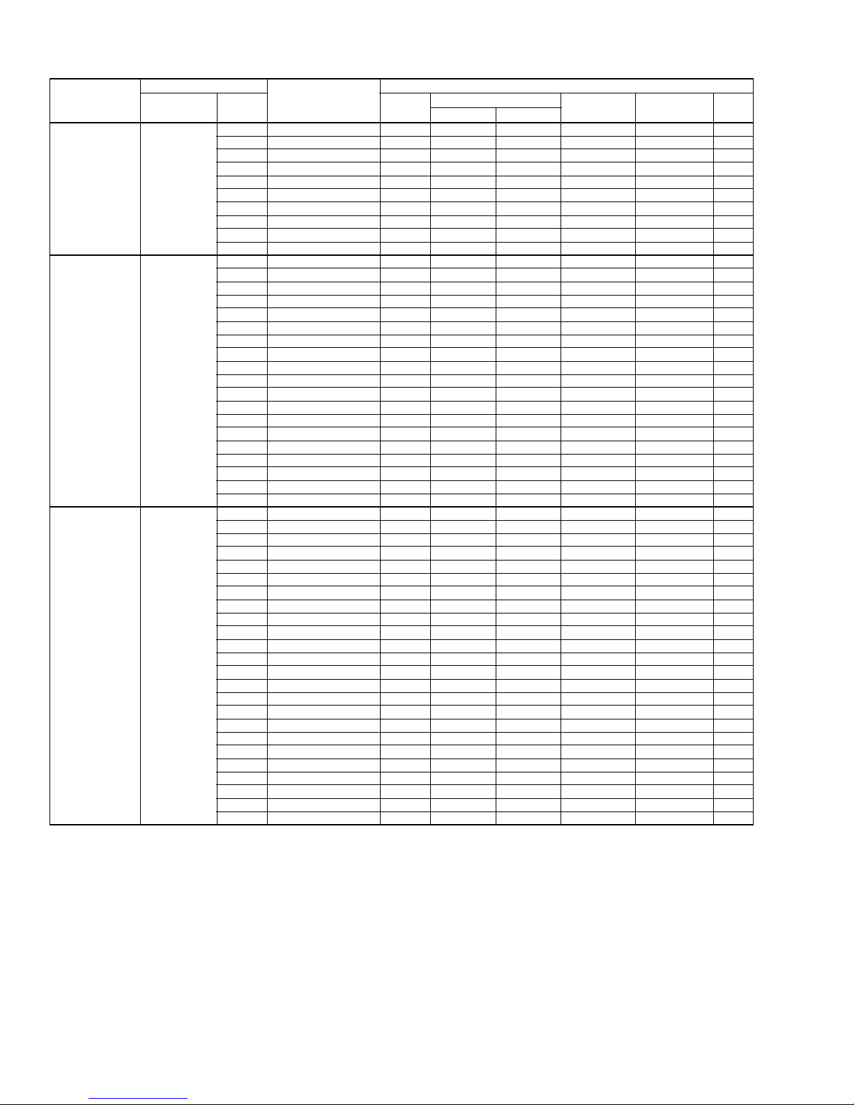
COOLING CAPACITY - Upflow, Downflow & Horizontal Furnaces and Coils
UNIT MODEL
AC018X1222
AC024X1222
AC030X1222
For Notes See Page 5.
FURNACE**
CFM RANGE
(MIN.-MAX.)
525
675
650
850
875
1125
COIL
W
MODEL
RATED
CFM
NET MBH
TOTAL SENS.
14,17 G1FA024S14,17 600 19.2 13.0 12.00* 12.00 11.35
14 G1HA024H14 600 19.2 13.6 12.00*
14 G1HA024H14T 600 19.2 13.6
- G1HD024 600 20.0 13.5 12.50* 12.50 11.70
17 G1NA030S17K 600 20.0 13.5 12.75* 12.75 11.75
21 G1NA030S21M 600 20.0 13.5 12.50* 12.50 11.75
14,17 G1UA024S14,17 600 19.2 13.0 12.00* 12.00 11.35
14,17 G2FD024(S,H)14,17 600 19.6 13.2 12.50* 12.50 11.60
17 G2FD030(S,H)17 600 20.0 13.5 12.60* 12.60 11.75
14 G2FD035(S,H)14 600 20.0 13.5 12.60* 12.60 11.75
14,17 G1FA024S14,17 750 23.0 16.4 11.80* 11.80 10.70
14 G1FA030S14 750 23.6 16.9 12.00* 12.00 11.00
14 G1FA036S14 750 24.2 17.6 12.00* 12.00 11.25
17,21 G1FA036S17,21 750 24.0 17.3 12.00* 12.00 11.10
14 G1HA024H14 750 19.2 13.6 12.00*
14 G1HA024H14T 800 23.5 16.7
14 G1HA036H14 800 24.6 17.5 12.00
- G1HD024 750 24.0 17.2 12.00* 12.00 11.05
- G1HD036 750 24.6 17.6 12.10* 12.10 11.35
17 G1NA030S17K 750 24.0 17.2 12.00* 12.00 11.15
21 G1NA030S21M 750 24.0 17.2 12.00* 12.00 11.15
14,17 G1UA024S14,17 750 23.0 16.4 11.80* 11.80 10.70
14 G1UA030S14 750 23.6 16.9 12.00* 12.00 11.00
14 G1UA036S14 750 24.2 17.6 12.00* 12.00 11.25
17,21 G1UA036S17,21 750 24.0 17.3 12.00* 12.00 11.10
14,17 G2FD024(S,H)14,17 750 23.6 16.9 12.00* 12.00 11.00
17 G2FD030(S,H)17 750 24.0 17.3 12.00* 12.00 11.10
14 G2FD035(S,H)14 750 24.0 17.3 12.10* 12.10 11.10
17 G2FD036(S,H)17 750 24.6 17.8 12.15* 12.15 11.35
14 G1FA030S14 1000 29.2 20.7 11.85* 11.85 10.80
14 G1FA036S14 1000 30.4 21.6 12.00* 12.00 11.10
17,21 G1FA036S17,21 1000 30.0 21.3 12.00* 12.00 11.00
17 G1FA048S17 1000 31.2 22.3 12.50* 12.50 11.45
21 G1FA048S21 1000 31.2 22.3 12.50* 12.50 11.35
14 G1HA036H14 1000 30.3 21.5 12.00*
14 G1HA036H14 1000 30.2 21.4
17 G1HA036H17 1000 30.4 21.9 12.00*
17 G1HA036H17T 1000 30.5 22.0
- G1HD036 1000 30.8 21.9 12.75* 12.75 11.25
17 G1NA030S17K 1000 30.2 21.4 12.00* 12.00 11.05
21 G1NA030S21M 1000 30.2 21.4 12.00* 12.00 11.05
17 G1NA036S17L 1000 31.4 22.3 12.50* 12.50 11.45
14 G1UA030S14 1000 29.2 20.7 11.85* 11.85 10.80
14 G1UA036S14 1000 30.4 21.6 12.00* 12.00 11.10
17,21 G1UA036S17,21 1000 30.0 21.3 12.00* 12.00 11.00
17 G1UA048S17 1000 31.2 22.3 12.50* 12.50 11.45
21 G1UA048S21 1000 31.2 22.3 12.50* 12.50 11.35
17 G2FD030(S,H)17 1000 30.0 21.3 12.00* 12.00 11.00
14 G2FD035(S,H)14 1000 30.0 21.3 12.00* 12.00 11.00
17 G2FD036(S,H)17 1000 30.6 21.8 12.25* 12.25 11.20
21 G2FD036(S,H)21 1000 30.8 21.9 12.25* 12.25 11.25
21 G2FD042(S,H)21 1000 31.0 22.1 12.50* 12.50 11.35
17 G2FD046(S,H)17 1000 31.4 22.3 12.50* 12.50 11.45
COOLING
W/O TXV
SEER
–
– 12.00* 10.90
– 12.00* 11.25
– 12.00* 11.35
SEER + TXV
12.00* 11.60
1
–
– 10.90
– 11.35
– 11.25
– 11.35
EER
11.50
6 Unitary Products Group
 Loading...