

Page 1
®
SUNLINE 2000
SINGLE PACKAGE HEAT PUMPS
INSTALLATION INSTRUCTION
MODELS B*CH 036 AND 048 (STYLE B)
GENERAL
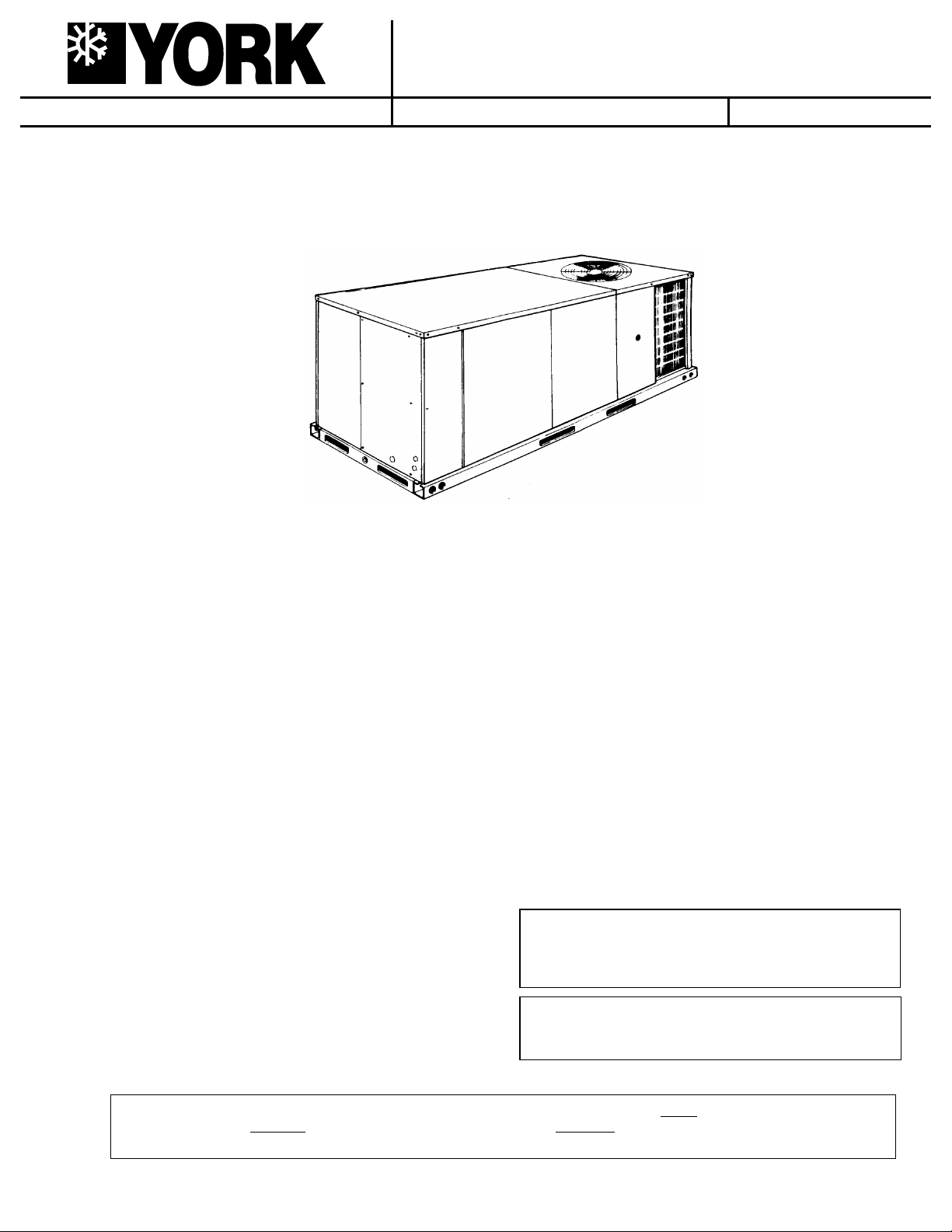
YORK Model BCH units are single package heat pumps
designed for outdoor installation on a rooftop or a slab.
Supplemental electric heate rs are available as field-instal led
accessories.
The units are completely assembled on rigid, permanently
attached base rails. All pipi ng, refrigeran t charge, a nd electrical
wiring is factory-installed and tested. The units require only
electric power and duct co nnecti ons at the po int of i nstall ation.
Supersedes: 511.06-N5Y (1298)
AND MODELS B*CH 060A (STYLE A)
(10 SEER - w/Belt-Drive Option)
(* = 3 or 5)
Replacement Parts:
Refer to Parts M anual for complete li sting of replacem ent
•
part s on this equipment.
All forms referenced in this instruction may be ordered from:
Standard Register
Norman, OK 73069
T oll Free: Tel. 877-318-9675/Fax. 877-379-7920
511.06-N5Y (500)
035-16197
The supplemental electric heaters have nickel-chrome
elements and utilize single point power connection.
INSPECTION
As soon as a unit is received, it should be inspected for possible
damage during transit. If damage is evident, the extent of the
damage should be note d on the carrier’ s fre ight bil l. A se parate
request for inspection by the carrier’s agent should be made in
writing. Refer to Form 50.15-NM for additional information.
REFERENCE
Additional information on the design, installation, operation and
service of this equipment is av ailab le in the f ollo wing ref erence
forms:
55.70-N1 -General Installation
•
55.70-N2 -Pre-start & Post-start Check List
•
530.18-N1.2V -Economiz er Acces so ry
•
530.18-N1.13V -Man. Outdoor Air Damper Accy 0-35%
•
530.18-N1.14V -Man. Outdoor Air Damper Accy 0-100%
•
530.18-N1.12V -Motorized Outdoor Air Damper Accy.
•
530.18-N7.1V -Electric Hea te r Acce ss ory
•
530.18-N7.2V -Fuse Block Accessory
•
Installer shou ld pay particular attent ion to the word s: NOTE, CAUTION and WARNING. Notes are intended to clarify or make
the installation easier. Cautions are given to prevent equipment damage. Warnings are given to alert installer that personal injury
and/or equipmen t da ma ge may result if inst a ll at io n pro ce du r e is not han dl ed properly.
APPROVALS
Design certified by U.L. and C.G.A. as follows:
1. For use as a heat pump only unit or a heat pump unit with
supplemental electric heat.
2. For ou td oo r inst a ll at io n on ly.
3. For in stallation on combustibl e ma te ria l.
LIMITATIONS
CAUTION
THIS PRODUCT MUST BE INSTALLED IN STRICT COMPLIANCE WITH
THE ENCLOSED INSTALLAT I ON I NST RUCTIONS AND ANY APPLI CABL E
LOCAL, STATE, AN D NA TIONAL CODES I NCLUDING, BUT NOT LIMIT E D
TO, BUILDING, ELECTRICAL, AND MECHANICAL CODES.
WARNING
I NCORRECT INSTALLATION MAY CREATE A CONDITION WHERE THE
OPERATION OF THE PRODUCT COULD CAUSE PERSONAL INJURY
OR PROPERTY DAM AGE.
Page 2
511.06-N5Y
TABLE OF CONTENTS
General................................................................................ 1
Inspection............................................................................. 1
Reference............................................................................. 1
Approvals ............................................................................. 1
Nomenclature....................................................................... 2
INSTALLATION
Limitations............................................................................3
Location ...............................................................................3
Condensate Drainage Precaution.......................................3
Rigging and Handling .......................................................... 3
Clearances...........................................................................3
Ductwork .............................................................................. 3
Filters ................................................................................... 4
Condensate Drain................................................................4
Service Access .................................................................... 4
Blower Speed Selection....................................................... 4
Disconnect Switch Bracket For Optional Belt-Drive ............ 4
Compressors........................................................................ 4
Thermostat...........................................................................4
Power and Control Wiring.................................................... 4
Electric Heaters ................................................................... 5
Optional Economizer Rain Hood.............................. .. .........6
OPERA T ION
Cooling System.................................................................. 12
Preliminary Opera tion Cooling................................. .......... 12
Cooling Sequence of Operation....... .............. .............. ......12
Heating Sequence of Operation................. .. .. .. .............. ...12
Defrost Sequence of Operation......................................... 12
Lockout Control..................................................................13
Checking Supply Air CFM....... .. .............. .. .. .............. .. .. .. ...13
Secure Owner’s Approval .................................................. 14
MAINTENANCE
Normal Maintenance ....... .................................................. 14
TABLES
No. Description Page
1 Unit Application Data................ .. .. .. ............ 3
2 Air Flow Limitati on s..... .. .. .. .. .............. .......... 5
3 Physical Data.............................................. 7
4 Supply Air Perf.
5 Supply Air Perf.
6 Supply Air Perf.
3 & 4 Ton w/Belt-Drive Blower
5 Ton w/Belt-Drive Blower
w/Di rect - D ri ve B l o w e r.......... 10
.. 9
........ 10
7 Static Resistances ...................................... 10
8 Motor and Drive Data - Belt-Drive Blower .. 11
9 Electrical Data w/Direct-Drive Blower......... 11
10 Electrical Data w/Belt-Drive Blower............ 11
11 Belt-Drive Sup pl y Air Moto r Pulley Adj.
......
13
FIGURES
No. Description Page
1 Center of Gravity......................................... 3
2 Recommended Drain Piping....................... 4
3 Typical Field Wiring..................................... 5
4 Economizer Rain Hood Assembly.............. 6
5 Adjusting Enthalpy Setpoint........................ 7
6 Dimensions and Clearances....................... 8
7 Defrost Initiati on Times............... ...... ...... .... 12
8 Ambient Modified Time/Temp. Control........ 12
9 Hole Loc. for Press. Drop Readings ........... 13
10 Press. Drop versus Supply Air CFM........... 13
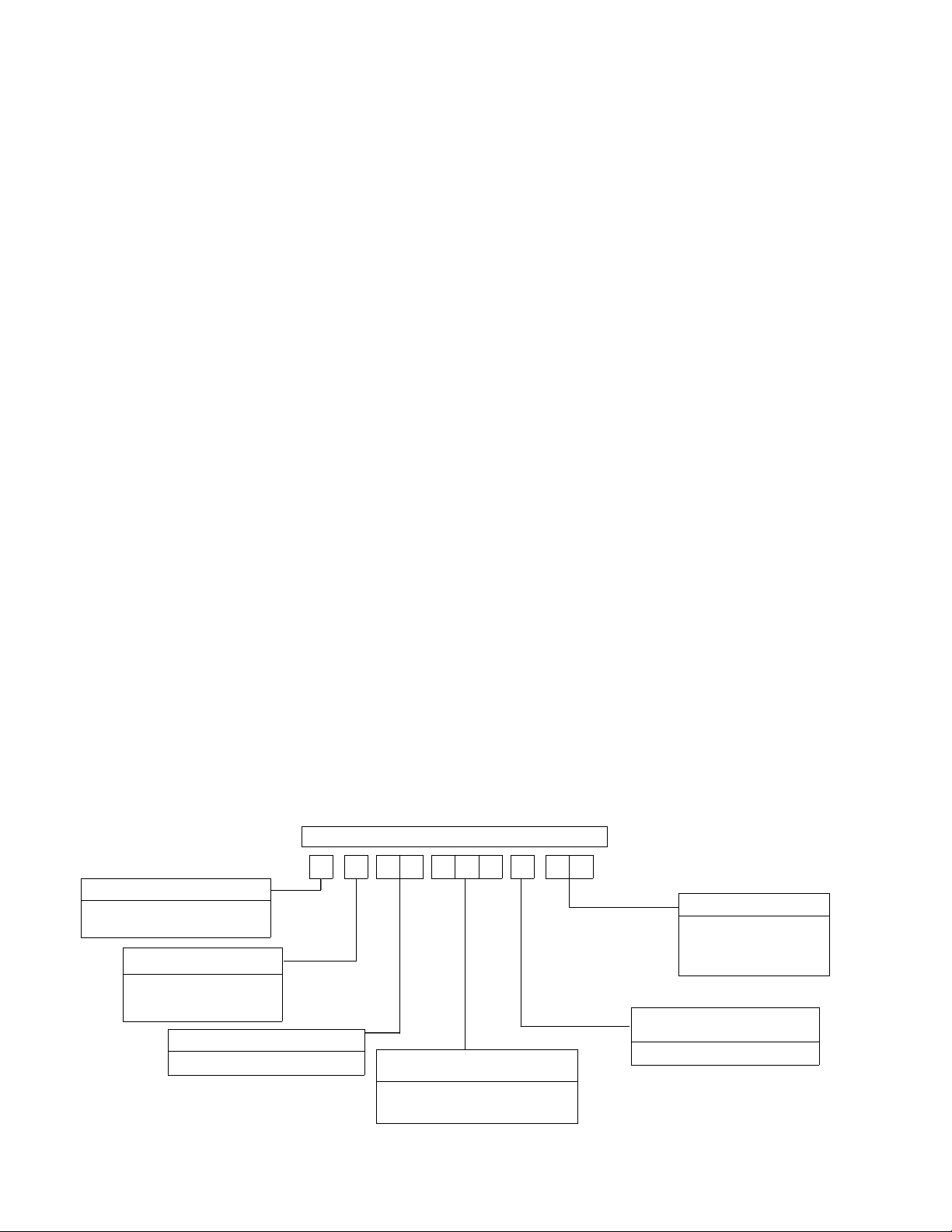
PRODUCT NOMENCLATURE
B 3 C H A
PRODUCT CATEGORY
B = Single Package Heat Pump
(Air Cooled)
PRODUCT GENERATION
3 = Third Generation
4 = Fourth Generation
5 = Fifth Generation
PRODUCT IDENTIFIER
CH = Heat Pump
2 Unitary Products Group
NOMINAL COOLING CAPACITY
30 6 2 5
036 = 3 Ton
048 = 4 Ton
060 = 5 Ton
VOLTAGE CODE
06 = 208/230-1-60
25 = 208/230-3-60
46 = 460-3-60
58 = 575-3-60
FACTORY INSTALLED HEAT
A = No Supplemental Heat
Page 3
INSTALLATION
These units must be installed i n accordanc e with the curren t
edition of the following national and local safety codes:
In U.S.A.:
1. National Electrical Code ANSI/NFPA No. 70.
2. Local elec tric ut il ity requirements .
In Canada:
1. Canadian El ectrical Code C22.1
2. Canadian Installation Codes CAN/CGA-B149.1 and .2.
Refer to Table 1 for Unit Applic at ion Data.
If components are to be added to a unit to meet local codes, they
are to be installed at the dealer’s and / or the customer’ s expense .
511.06-N5Y
WARNING: The unit should not be installed in an area where mud
or ice could cause personal injury. Remember that
condensate wil l drip fro m the ou tdoor co il during heat
and defrost cycle s and that this co ndensate will freeze
when the temperat ure of the outdoor air is below 32°F.
RIGGING AND HANDLING
Exercise care when moving the unit. Do not remove any
packaging until the unit is near the place of installation. Rig the
unit by attaching chain or cable slings to the lifting holes
provided in t he base rails. Spreaders, wh ose length exceed s
the larges t dime nsion across the uni t, MUST be used acros s
the top of the unit.
BEFORE LIFTING A UNIT, MAKE SURE THAT ITS WEIGHT
IS DISTRIBUTED EQUALLY ON THE CABLES SO THAT IT
WILL LIFT EVENLY.
Size of unit for propos ed in st al la tion sh ou ld be ba sed on hea t
loss / heat gain calculation made according to the methods of
Air Conditioning Contractors of America (ACCA).
LOCATION
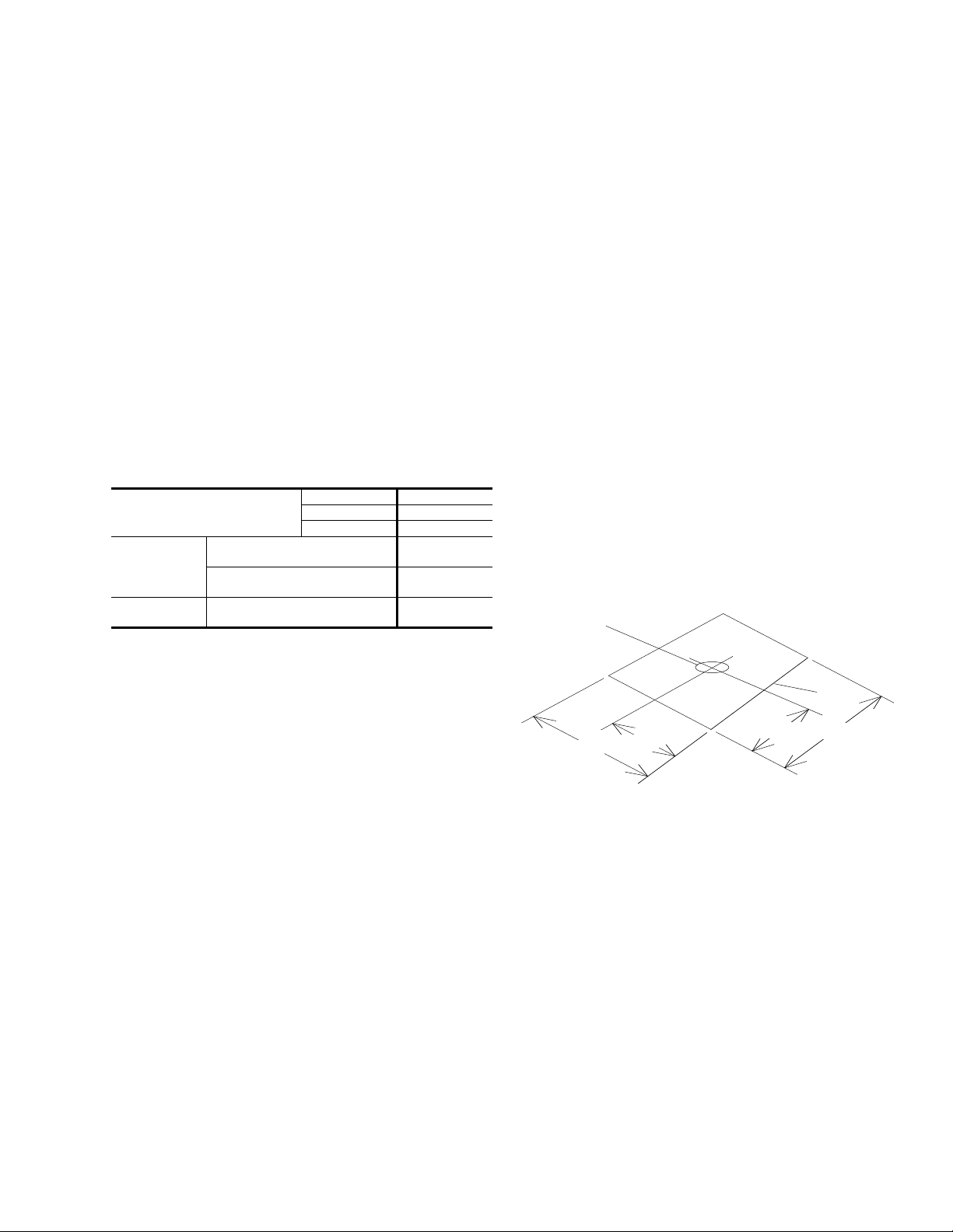
TABLE 1
*Rated in accordance with ARI Standard 110, utilization range "A".
Use the following guidelines to sele ct a suitable location for
these units.
1. Unit is designed for outdoor installation only.
2. Outdoor coil must have an unlimited supply of air.
3. For ground level installation, a level pad or slab should be
4. Roof structures must be able to support the weight of the unit
- UNIT APPLICATION DATA
V oltage V ariation
Min. / Max.*
Wet Bulb Temperature (°F) of Air
Cooling
Heating
on Indoor Coil, Min. / Max.
Dry Bulb Temperature (°F) of Air
on Outdoor Coil, Min. / Max.
Minimum Dry Bulb T emper ature
(°F) of Air on Outdoor Coil
used. The thickn ess and size of the pa d or slab used should
meet local codes and unit weight. Do not tie the slab to the
building foundation.
and its options and / or accessories. Unit m ust be installed on
a solid level roof curb or appropriate angle iron frame.
208/230V 187 / 253
460V 414 / 506
575V 518 / 630
57 / 72
45 / 120
-10
Units may also be moved or lifted with a forklift. Slotted
openings in the base r ai ls ar e provided for th is purpose .
LENGTH OF FORKS MUST BE A MINIMUM OF 42".
Remove the nesting b rackets from th e four corn ers on to p of
the unit. All screws that are removed when taking these
brackets off must be replaced on the unit.
Refer to T able 3 for unit weights and to Figure 1 for approximate
center of gravity.
CLEARANCES
All units req uire cer tain clearances for prop er operation and
APPROXINATE
CENTER OF
GRAVITY
FRONT
3
⁄
19
7
⁄
44
“
8
FIG. 1
- CENTER OF GRAVITY
3
⁄
“
4
40
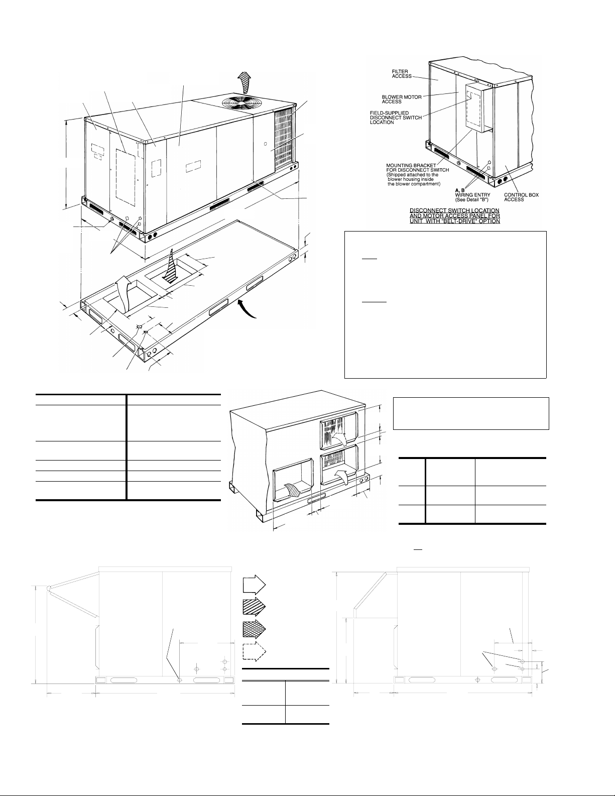
service. Refer to Figure 6 for the clearances required for
combustib le construct ion, servicing, an d proper unit op eration.
WARNING:Do not permit overhangin g s tru ct ure s or sh rub s to
obstruct outdoor air di sc ha rge out le t.
1
“
⁄
82
4
“
4
CAUTION: If a unit is to be installed on a roof curb or special frame
DUCTWORK
other than a YORK roof curb , gasketing must be applied to
all surfaces that come in contact with the unit underside.
Ductwork should be designed and sized according to the
methods in Manual Q of the Air Conditioning Contractors of
5. Maintain le v el tole rance t o 1/2" m aximum a cross th e entire
America (ACCA).
length or width of the unit.
A closed return duct system shall be used. This shall not
6. Elevate the unit sufficiently to prevent any blockage of the
air entrances by snow in areas where there will be snow
accumulation . Check the local weathe r bureau for the ex-
preclude u se of ec onomizers or outd oor fres h air inta ke. The
supply and r eturn air duct connections at t he unit should be
made with flexible j oint s to m inimiz e th e tr ansm issi on o f no ise .
pected snow accumulation in your area.
The supply and return air duct systems should be designed for
OUTDOOR COIL CONDENSA TE DRAI NAG E PRECA UTION
Condensate will drain from the outdoor coil during the heating
and defrost cycles. Normally this condensate may be allowed
to drain directly onto the ground/roof. A gravel bed is
recommended to prevent mud splashing.
Unitary Products Group 3
the CFM and static requirements of the job. They should NOT
be sized to matc h the dime nsions of the duct connect ions on
the unit.
CAUTION: When fastening duc twor k to the side duct fl ange s
on the unit, insert the screws through the duct
flanges only. DO N OT insert the sc rews through t he
Page 4

511.06-N5Y
casing.
Outdoor ductw ork must be insulated and waterproofed.
Refer to Figure 6 for infor mation concerning side and bottom
supply and return air duct openings.
FILTERS
1" filters are supplied with each unit. 2" replacement filters may
be used with no modification to the filter racks. Filters must
always be installe d ahead of the evaporator c oil and must be
kept clean or rep laced wit h same siz e and type . Dirty filte rs will
reduce the capacity of the unit and will result in frosted coils or
safety shutdown. Minimum filter area an d required sizes are
shown in T able 3.
Figure 6. Several existing screws at the top of the unit and one
approximately midway down from the top will be used for
mounting the bracket. Screws should be lo os ened onl y - NOT
REMOVED. Mounting holes in the bracket have elongated
keyways allowing easy installation. Re-tighten screws after
bracke t is in pl ac e to ens ure pan el s wil l rem ai n le ak t ight.
COMPRESSORS
On some units the co mpressor is mounted on spr ings which
have been tightened down for shipment only.
After this un it is in stalle d, back out the compre ssor bo lts unti l
the sleeve clears the top g r om me t.
CAUTION: Do Not loosen compressor mounting bolts.
CONDENSATE DRAIN
Plumbing must conform to local codes. Use a sealing
compound on male pipe threads. Install a condensate drain line
from the 3/4" PVC f emale conn ection on the un it to spill into an
open drain.
NOTE: The condensate drain line MUST be trapped to provide
proper drainage. See Figure 2.
SERVICE ACCESS
FIG. 2
- RECOMMENDED DRAIN PIPING
Access to all serviceable components is provided by the
follo w in g rem o vable pane ls :
Compressor compartment
•
Heater compartment
•
Blower compartment
•
Main control box
•
Filter compartment
•
Motor Access (on units w /b el t-d rive option)
•
Refer to Figure 6 for locati on of th es e ac ce ss pan el s .
BLOWER SPEED SELECTION
Three blower motor speeds are available on the di rect-drive
units. The speed selection for the direct-drive units is
determined by the CFM and ESP requirements of the
applications. Al l units with belt-drive optio n have an a dj us ta ble
motor pulley to achieve the above conditions.
All direct-drive units are shipped with the black wire (labeled
#8) connected to the high speed tap on the blower motor. If a
lower blo wer speed is desire d, this wire shou ld be mov ed to the
medium or low speed tap on the motor.
DISCONNECT SWITCH BRACKET FOR UNITS
WITH OPTIONAL BELT-DRIVE BRACKET
A special bracket for mounting a field-supplied disconnect
switch is provided in each unit ordered with an optional
belt-drive supp ly air blower. The bracket is shipped inside the
blower compartment taped to the top of the blower housing.
Install the bracket on the left hand side of the unit as shown in
THERMOSTAT
The room thermostat should be located on an inside wall
approximately 56" above the floor where it will not be subject
to drafts, sun exposure, or heat from electrical fixtures or
appliances. Follow manufacturer’s instructions enclosed with
thermostat for general installation procedure. Color coded
insulated wires (#18 AWG) should be used to connect
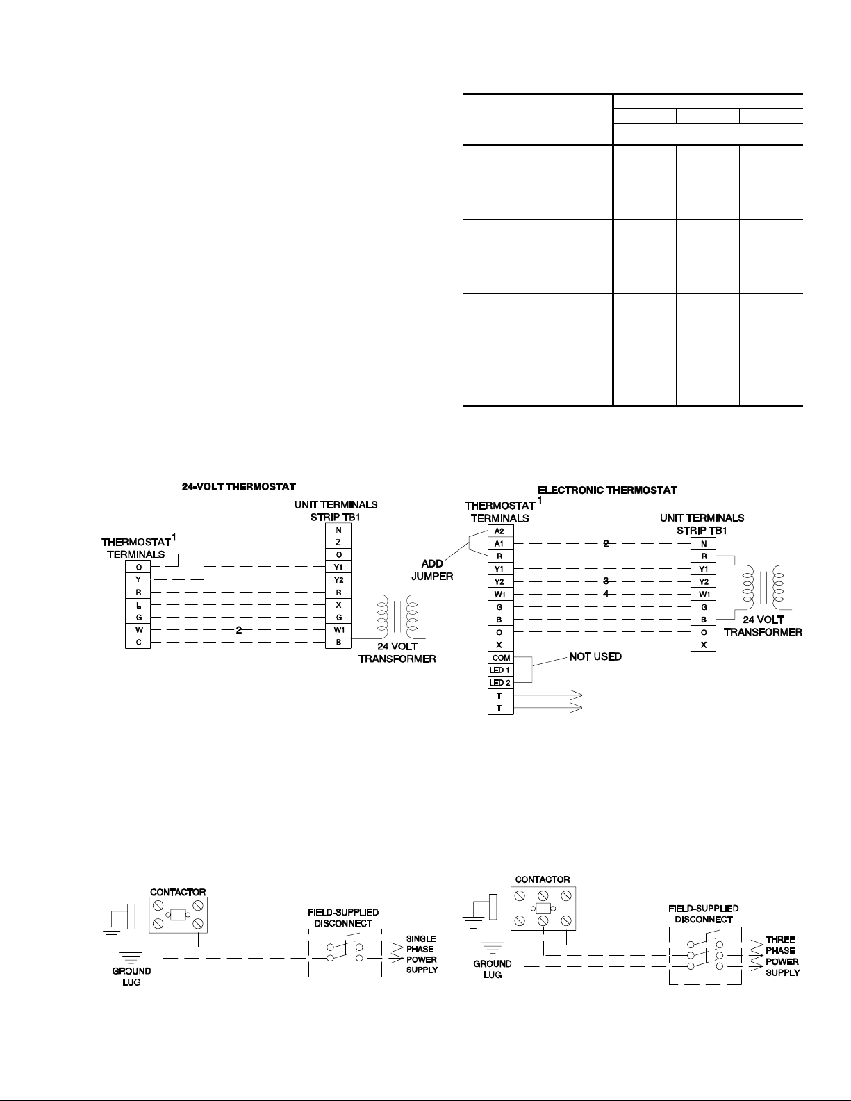
thermostat to unit. See Figure 3 for w iring det ai ls.
NOTE: On units with econ omizer, remove jumper "J1" from
termin als 8 and 10 on plug connector J3/P 7 on the
relay board in the unit control box. Refer to the unit
wiring labels located on the inside of the control box
access panel.
An "Emergency Heat" position is provided with the thermostat.
In the "Emergency Heat" position, the thermostat will allow
electric resistance heat only. The compressor will be locked
out. A pilot light on the thermostat will indicate that the switch
is on "EM HT".
POWER AND CONTR OL WIRING
Field wiring to the unit must conform to provisions of the National
Electrical Code (NEC) ANSI/NFPA No. 70 (in U.S.A.), current
Canadian Electrical Code (CEC) C22.1 (in Canada) and/or local
ordinances. The unit must be electrically grounded in accordance
with the NEC and CEC (as specified above) and/or local codes.
V oltage tolerances which m ust be maintained at the compressor
terminals during starting and running conditions are indicated on
the unit Rating Plate and T ab le 1.
The wiri ng har n ess fu rni shed w ith t his un it is an int egral part
of a UL and C.G.A. design certified unit. Field alteration to
comply with electrical codes should not be required.
A disconnect switch should be field provided for the unit. The
switch must be separate from all other circuits. Refer to Figure
6 for installation location. If any of the wire supplied with the unit
must be replaced, replacement wire must be of the type shown
on the wiring diagram.
Electrical lines must be sized properly to carry the load. USE
COPPER CONDUCTORS ONLY. Each unit must be wired with
a separate branch circuit fed directly from the meter panel and
properly protected.
CAUTI ON: When connecting electrical power an d contro l wi r-
ing to the unit, waterproof type connectors MUST
BE USED so that water or moisture cannot be
drawn into the unit during normal operation. The
above waterproofing conditions will also apply
when install ing a field-sup plied disconnect switch.
Refer to Figure 3 for typical field wiring and to the appropriate
unit wiring diagram for control circuit and power wiring
information. Refer to Tables 9 and 10 for electrical data.
4 Unitary Products Group
Page 5
ELECTRIC HEATERS
Supplemental electric heaters may be ordered as a
field-installed accessory. Refer to Form 530.18-N7.1V for
installation instruction . The se UL and C .G. A. appro ve d heaters
are located within the central compartment of the unit (see
Figure 6 for ac cess panel) wi th the heati ng elements e xtendi ng
into the supply air chamber.
Fuses are supp li ed , whe re r eq ui red , by the factory. Some KW
sizes require fuses and others do not. Refer to the electric
heater accessory installation instruction for the heater electrical
data.
The minimum air flow limitations across these heaters are listed
in Table 2.
TABLE 2
NOMINAL
- AIR FLOW LIMITATIONS
HEATER
SIZE
VOLT AGE
UNIT MODEL SIZE, NOMINAL TONS
1
KW
1,100
1,100
1,200
1,200
1,300
10
15
20
5
7
208 /
230-1-60
30
1,100
1,100
1,200
1,200
1,300
10
15
20
5
7
208 /
230-3-60
30
10
15
20
7
460-3-60
1,100
1,200
1,200
1,300
30
10
15
20
575-3-60
1,200
1,200
1,300
30
1208/230 and 46 0 v olt heaters are UL appro v ed .
208/230 and 575 volt h eaters are CGA approved.
2
CGA minimum is 1,40 0 C FM .
511.06-N5Y
345
MINIMUM SUPPLY AIR CFM
1,300
1,300
1,300
1,300
2
–
1,300
–
1,300
1,300
1,300
1,300
2
1,300
–
–
1,300
1,300
1,300
1,300
–
–
1,300
1,300
1,400
–
–
1,600
1,600
1,600
1,600
2
1,600
1,600
1,600
1,600
1,600
1,600
1,600
1,600
1,600
1,600
1,600
1,600
1,600
1,600
1,600
1,600
1,800
1
24-volt thermostat with subbase;
-2TH11704024 for manual changeover.
-2TH11704124 for automatic changeover.
2
Only required on units with supplemental electric heat.
CONTROL WIRING
1
Electronic progammable thermostat 2ET04700324 with subbase for either
manual or automatic changeover.
2
Only required on units with economizer. Remove jumper L2 from terminals
4 and 9 on jumper plug P7. The outdoor air intake dampers will return to their
fully closed position when the thermostat switches to the “unoccupied” mode.
3
Second stage cooling may be used on units with economizer. Remove jumper
J1 from terminals 8 and 10 on jumper plug connector P7.
4
Only required on units with supplemental electric heat.
POWER WIRING
TO REMOTE SENSOR
2TH04702224 IF USED
REFER TO ELECTRICAL DATA
T ABLES TO SIZE THE DISCONNECT
SWITCH, THE WIRING AND THE
OVERCURRENT PROTECTION.
FIG. 3
- TYPICAL FIELD WIRING
REFER TO ELECTRICAL DATA
T ABLES TO SIZE THE DISCONNECT
SWITCH, THE WIRING AND THE
OVERCURRENT PROTECTION.
Unitary Products Group 5
Page 6
511.06-N5Y
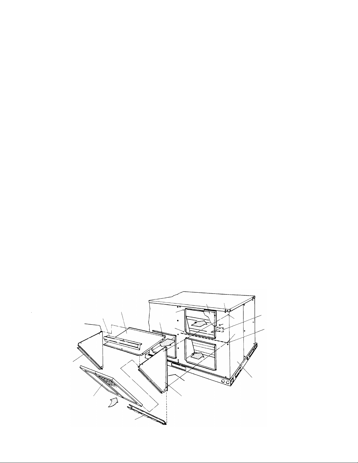
OPTIONAL ECONOMIZER RAIN HOOD
The following proced ure sh ou ld be us ed when ass em bling an
economizer rai n hood onto a unit. Ref er to Figure 4. The ou tdoor
and return air dampers, damper actuator, the linkage and all
the controls a re factory mounted as pa rt of the economizer
option.
All of the hood c ompo nent s, incl udin g t he fi lters , the gask e ting
and the hardware f or assemblin g are located abov e the top filte r
racks within th e filte r section . The outdoor air sens or is in th e
bag of parts located at the bott om of th e ret urn air section.
1. With filter section access panel removed, take out hood
components, filters and sensor described above. Remove
and discard outdoor air opening cover on back unit (Upper
right hand corner).
2. Remove the 1/2" knockout (A) in the units rear panel
(located to the right side of the outdoor air opening). Insert
the two loose wires from inside the unit, into the 1/2"
bushing provided. Inser t w ires a nd bushi ng in to knockout.
Snap bushing into place.
3. Mount the outdoor air sensor to the rear panel, just below
the knocko ut described in Step 2. Secure with t wo self-drill ing screws at dimples (B) provided in the panel.
NOTE: Sensor must be positioned so that the sensing ports
4. Connect th e two wires, indicated i n Step 2, to th e sensor as
•
•
5. Assemble the LH and RH side pl ates to the top cover (2
are at the top (louvers pointing downward) and terminal
connections to the right.
follows:
Wire #73 to terminal (+)
Wire #74 to terminal (S)
screws each side) to f orm the hood . App ly gask eting to the
flange surface on each side plate. Extend gasketing 1/4"
beyond top and bottom of each flange to insure adequate
corner sealing. Secure this assembly to the unit back panel
(upper right hand corner). First, remove screw (C) on unit
top cover. Then slip flan ge of hoo d co v e r in unde r fla nge of
unit top cov er, replace screw (C), en gaging hole (E) in hood
flange and tighten. Attach the two side plates to the unit
panel by using two self-drilling screws for each side plate
at dimples (D) provided in the panel.
6. Position fillpiece at bottom of hood, between the two side
plates but do not secure at this time. (Slotted openings
MUST be downward for drainage). After fillpiece is properly
positioned, n ote wh ere cont act i s made w ith t he uni t pa nel.
Remove fillpiece a nd ap ply gas ket mate r ial t o this a rea to
provide a seal. Reposition fillpiece and secure with 2
screws.
7. Install the two filters into the hood assembly, sliding down
along retainers on side plates, into fillpiece at bottom of
hood.
NOTE: Install filters so that "Air Flow" arrows point toward the
unit.
8. Install filt er c over over the e nd of th e ho od with one scr ew
(center of hood), securing filters into position.
CAUTION: When proceeding with steps 9 and 10, extreme
care must be exercised while turning both the set
point and minimum position adjusting screws to
prevent twisting them off.
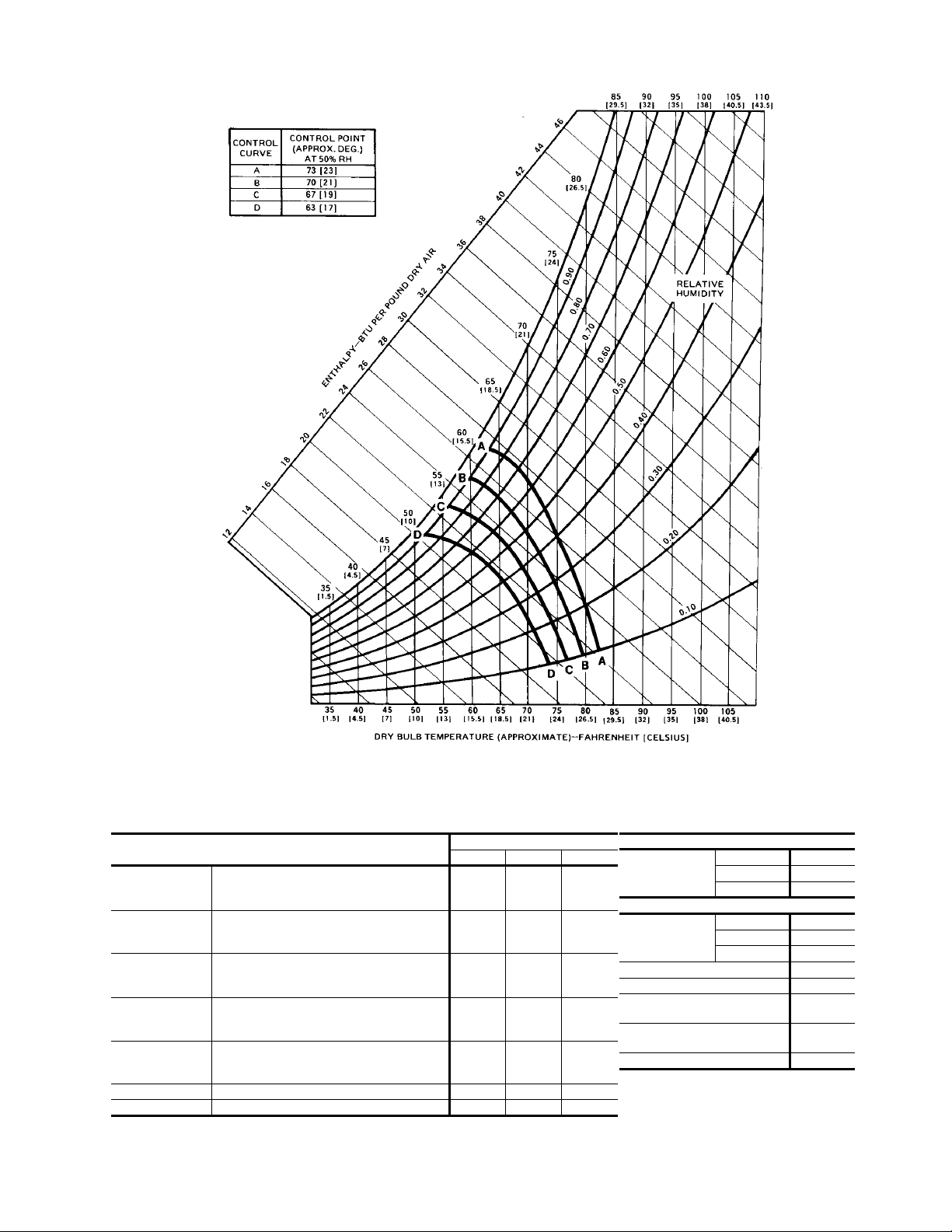
9. The enthal py set point for the dampers may now be set by
selecting th e des ire d set- poi nt from graph in Figure 5. For
a single enthal py economizer, carefully tur n the set-point
adjusting screw to the "A", "B", "C" or "D" setting corresponding to the lettered curve. For a dual enthalpy economizer, carefully turn the set-point adjusting screw fully
clockwise past the "D" setting.
10. To c heck that the damper blad es move smoothly without
binding, carefully turn the minimum position adjusting
screw fully cl ockwise and then energize and de -energize
termin als "R" t o "G". With termi nals "R" to "G" energ ized,
turn the minimum position screw counterclockwise until the
desired mini mum position has been attained.
11. Replace the filter section access panel.
OUTDOOR AIR
HOOD
FILTER
COVER
GASKETED
FLANGE
L. H. SIDE
PLATE
FILTERS
FIG. 4
- ECONOMIZER RAIN HOOD ASSEMBLY (OPTION)
6 Unitary Products Group
COVER
E
FILLPIECE
OPENING COVER
D
D
GASKETED
FLANGE
R. H.
SIDE
PLATE
C
D
A
B
D
SIDE DUCT
APPLICATION SHOWN
OUTDOOR AIR
SENSOR
GASKET
FILTER SECTION
ACCESS PANEL
Page 7
511.06-N5Y
FIG. 5
- ENTHALPY SET POINT ADJUSTMENT
TABLE 3
SUPPLY AIR
- PHYSICAL DATA
BLOWER
INDOOR
COIL
OUTDOOR
FAN
OUTDOOR
COIL
AIR
FIL TERS
(SEE NOTE)
MODELS
CENTRIFUGAL BLOWER (Dia. x W d. in.)
FA N MOTOR HP (Direct-Drive Units)
FA N MOTOR HP (Belt-Drive Units)
ROWS DEEP
FINS PER INCH
FACE AREA (Sq. Ft.)
PROPELLER DIA. (in.)
F AN MOTOR HP
NOM. CFM TOT A L
ROWS DEEP
FINS PER INCH
FACE AREA (Sq. Ft.)
QUANTITY P E R UNIT (15" x 20" x 1")
QUANTITY PER UNIT (14" X 25" X 1")
TO TAL FACE AREA (sq. ft.)
BCH
036 048 060
12 x 10
4,300
17.1
1
1.5
16
4.3
22
1
20
6.3
12 x 10
⁄
2
12 x 10
3
⁄
4
1.5
4
3
15
5.1
22
⁄
3
1
⁄
2
4,200
1
1
20
17.1
2
1
2
1
6.3
1
1.5
3
15
5.1
24
1
⁄
2
4,500
1
20
17.1
2
1
6.3
WEIGHTS (LBS)
3 Ton 555
Basic Unit
4 Ton 595
5 Ton 620
OPTIONS / ACCESSORIES
Electric Heat
(Nominal KW)
5 - 7 KW 18
10 - 15 KW 23
20 - 30 KW 28
Economizer 50
Belt-Drive Blower 5
Motorized Outdoor
Air Damper
Barometric Relief/Fixed
Outdoor Air Intake Damper
26
10
Roof Mounting Curb 92
CHARGE REFRIGERANT 22 (lbs./oz.) 7/12 8/4 8/4
COMPRESSOR HERMETIC, RECIPRICATING (Qty) 1 1 1
NOTE: Filter racks are adapted for 1" or 2" thick fil ters.
Unitary Products Group 7
Page 8
511.06-N5Y
(Direct-Drive Units)
FIELD-SUPPLIED
DISCONNECT SWITCH
FILTER ACCESS
LOCATION
5
32
BLOWER
ACCESS
CONTROL
BOX ACCESS
OUTDOOR
COIL
COMPRESSOR
ACCESS
⁄
8
FRONT VIEW
3
⁄
“ PVC FEMALE
4
COND. DRAIN
(See Detail ”A")
A, B
7
⁄
44
8
WIRING ENTRY
(See Detail “B”)
3
⁄
5
8
3
⁄
6
4
7
⁄
7
8
BOTTOM SUPPLY &
RETURN AIR OPENINGS
(SEE NOTE)
B - POWER WIRING ENTRY
A - CONTROL WIRING ENTRY
3
⁄
8
8
CLEARANCES
Front 24"
12" (Less Economizer)
Back
Left Side
(Filter Access)
Right Side (OD Coil) 24"
Below Unit
Above Unit
NOTE:
Units and ductwork are approved for zero clearance to combustible
materials when equipped with electric heaters.
1
Units may be installed on combustible floors made from wood or
class A, B or C roof covering material. (Applicable in USA only).
2
Units must be installed oudoors. Overhanging structures or shrubs
should not obstruct the outdoor coil nor the fan outlet.
1
2
36" (With Economizer or
Fixed Air/Motorized
Damper)
24" (Less Economizer)
36" (With Economizer)
20"
72" (For Outdoor Air
Discharge)
ELECTRIC
1
⁄
82
4
1
⁄
11
2
HEAT
ACCESS
1
⁄
2
2
DUCT COVERS - Units are shipped with all air duct
openings covered.
For
side duct applications;
1.Remove and discard the supply and return air duct
covers.
1
⁄
17
2
1
⁄
6
2
1
⁄
17
2
1
⁄
8
8
UNIT BASE WITH RAILS
Shown separately to illustrate bottom
duct openings and power connection
locations.
NOTE: For curb-mounted units, refer to the duct
hanger dimensions of the curb for the proper size
of the supply and return air duct connections.
2.Connect ductwork to duct flanges on the rear of the
unit.
For
bottom duct applications;
1. Remove the side supply air duct cover to gain
access to the bottom supply air knockout panel.
2. Remove and discard the bottom knockout panel.
3. Replace the side duct cover.
4. With filter section access panel remov ed from the
unit, remove and discard the bottom return air
knockout panel.
5. Replace the filter access panel.
All dimensions are in inches. They are subject to change without notice. Certified di-
1
⁄
11
2
mensions will be provided upon request.
3
1
⁄
11
2
UTILITIES ENTRY DATA
HOLE
KNOCKOUT
SIZE
USED FOR
5
⁄
4
8
(DIA.)
1
⁄
17
2
1
1
⁄
6
2
⁄
17
2
REAR VIEW
SIDE SUPPLY AND RETURN
AIR OPENINGS
7
⁄
7
8
A7/8" *
B2" *
*Knockouts in the bottom of the unit can be located
by the slice in the insulation.
Do not remove the 2" knockout ring.
**
Control Wiring
(Side or Bottom)**
Power Wiring
(Side or Bottom)
AIR FLOW LEGEND
RETURN AIR
7
⁄
30
8
1
⁄
10
4
1
⁄
19
8
B
A
"A"
7
⁄
44
8
DETAIL “B”
1
⁄
2
UNIT WITH FIXED OU TDOO R
AIR/MOTORIZED DAMPER RAIN HOOD
1
⁄
27
2
FIG. 6
3
⁄
“ CONDENSATE
4
DRAIN
(must be trappe d)
19
3
⁄
4
SUPPLY AIR
OUTDOOR AIR
OUTDOOR AIR
(Economizer)
DIMENSION "A"
1
⁄
19
2
7
⁄
44
8
DETAIL “A”
UNIT WITH ECONOMIZER RAIN HOOD
FIXED
OUTDOOR
AIR DAMPER
MOTORIZED
DAMPER
- DIMENSIONS & CLEARANCES - 3, 4 & 5 TONS
12
16
8 Unitary Products Group
1
⁄
3
2
1
⁄
8
4
3
⁄
4
8
Page 9
511.06-N5Y
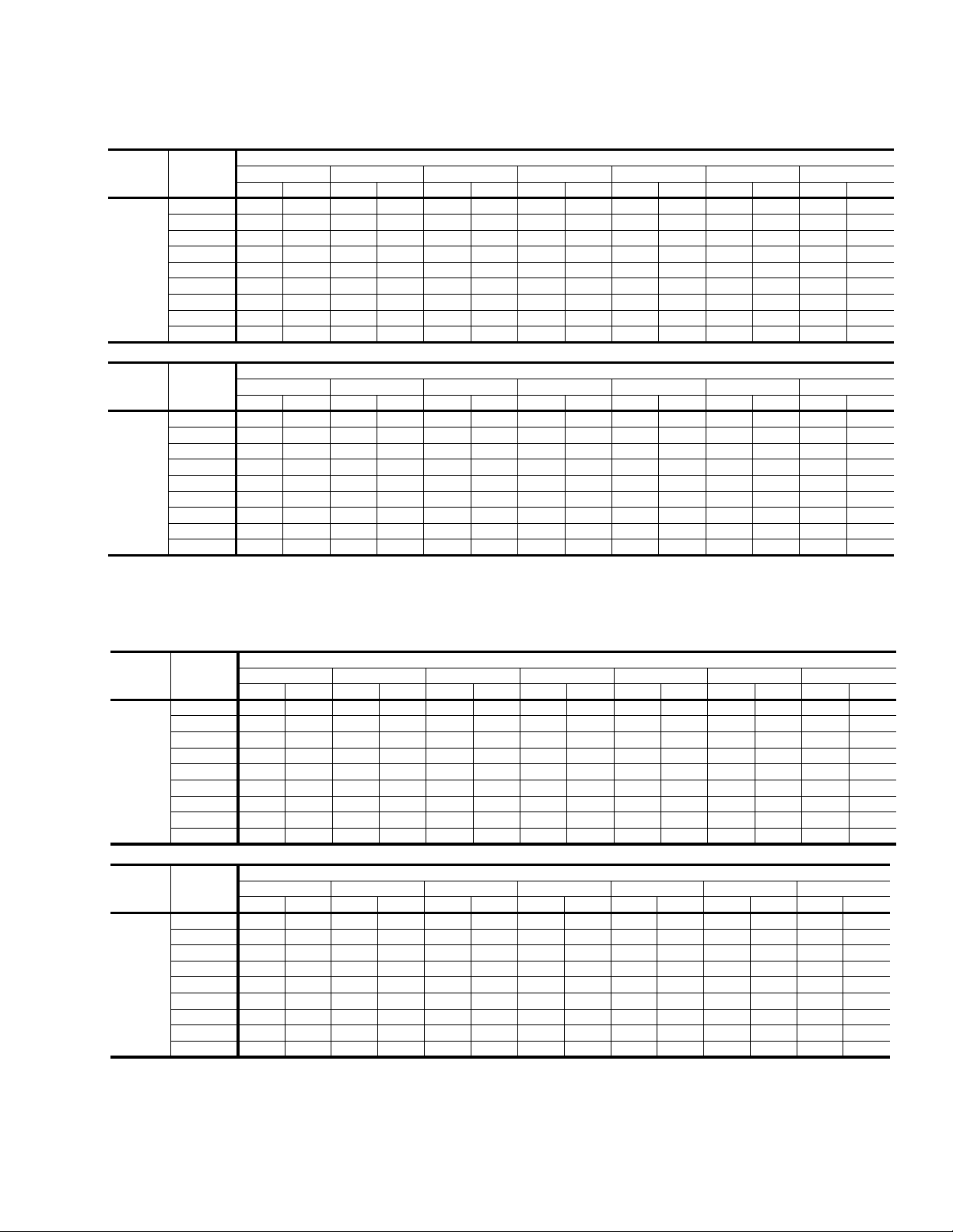
TABLE 4
- SUPPLY AIR PERFORMANCE - 3 & 4 Ton Units w/Belt-Drive Blower
3 TON - SIDE DUCT CONNECTIONS @230/460/575 Volts
MODEL
BCH
AIR FLOW
CFM
0.20 0.30 0.40 0.50 0.60 0.70 0.80
RPM Watts RPM Watts RPM Watts RPM Watts RPM Watts RPM Watts RPM Watts
2000 843 860 880 925 919 1005 956 1065 993 1145 1030 1195 1067 1235
1900 817 775 854 850 893 920 930 995 970 1065 1008 1125 1046 1170
1800 790 700 828 760 867 840 906 905 944 980 985 1040 1025 1100
1700 - - 802 670 840 745 881 815 920 900 961 970 1001 1030
036
1600 - - - - 818 665 858 740 898 820 940 890 980 950
1500 - - - - - - 842 695 882 755 922 835 962 895
1400 - - - - - - 833 650 867 705 904 765 942 820
1300 - - - - - - - - 858 665 893 725 932 785
1200 - - - - - - - - 847 640 880 680 916 730
MODEL
BCH
AIR FLOW
CFM
0.90 1.00 1.10 1.20 1.30 1.40 1.50
RPM Watts RPM Watts RPM Watts RPM Watts RPM Watts RPM Watts RPM Watts
2000 1103 1270 - - - - - - - - - - - 1900 1085 1210 - - - - - - - - - - - 1800 1064 1145 1102 1180 - - - - - - - - - 1700 1040 1075 1081 1115 1121 1140 - - - - - - - -
036
1600 1020 1005 1060 1050 1100 1085 - - - - - - - 1500 1003 945 1044 995 1086 1035 - - - - - - - 1400 982 880 1024 920 1067 965 1107 1000 - - - - - 1300 970 835 1010 870 1053 920 1099 960 - - - - - 1200 953 780 992 815 1034 855 1080 905 - - - - - -
NOTE: FOR 208 V O LTS, MULTIPLY VALUES B Y 0.95.
*INCLUDES ALLOWANCES FOR A WET INDOOR COIL AND 1" FILTERS. REFER TO TABLE 7 FOR RESISTANCE VAL UES ON APPLICATIONS OTHER THAN HEAT PUMP UNITS
WITH SIDE DUCT AIRFLOWS.
Available External Static Pressure - IWG*
Available External Static Pressure - IWG*
4 TON - SIDE DUCT CONNECTIONS @ 230/460/575 Volts
MODEL
BCH
AIR FLOW
CFM
0.20 0.30 0.40 0.50 0.60 0.70 0.80
RPM Watts RPM Watts RPM Watts RPM Watts RPM Watts RPM Watts RPM Watts
2000 843 860 880 925 919 1005 956 1065 993 1145 1030 1195 1067 1235
1900 817 775 854 850 893 920 930 995 970 1065 1008 1125 1046 1170
1800 790 700 828 760 867 840 906 905 944 980 985 1040 1025 1100
1700 - - 802 670 840 745 881 815 920 900 961 970 1001 1030
048
1600 - - - - 818 665 858 740 898 820 940 890 980 950
1500 - - - - - - 842 695 882 755 922 835 962 895
1400 - - - - - - 833 650 867 705 904 765 942 820
1300 - - - - - - - - 858 665 893 725 932 785
1200 - - - - - - - - 847 640 880 680 916 730
MODEL
BCH
AIR FLOW
CFM
0.90 1.00 1.10 1.20 1.30 1.40 1.50
RPM Watts RPM Watts RPM Watts RPM Watts RPM Watts RPM Watts RPM Watts
2000 1103 1270 - - - - -------1900 1085 1210 - - - - -------1800 1064 1145 1102 1180 - - -------1700 1040 1075 1081 1115 1121 1140 --------
048
1600 1020 1005 1060 1050 1100 1085 -------1500 1003 945 1044 995 1086 1035 -------1400 982 880 1024 920 1067 965 1107 1000 -----1300 970 835 1010 870 1053 920 1099 960 -----1200 953 780 992 815 1034 855 1080 905 ------
NOTE: FOR 208 V O LTS, MULTIPLY VALUES B Y 0.95.
*INCLUDES ALLOWANCES FOR A WET INDOOR COIL AND 1" FILTERS. REFER TO TABLE 7 FOR RESISTANCE VAL UES ON APPLICATIONS OTHER THAN HEAT PUMP UNITS
WITH SIDE DUCT AIRFLOWS.
Available External Static Pressure - IWG*
Available External Static Pressure - IWG*
Unitary Products Group 9
Page 10
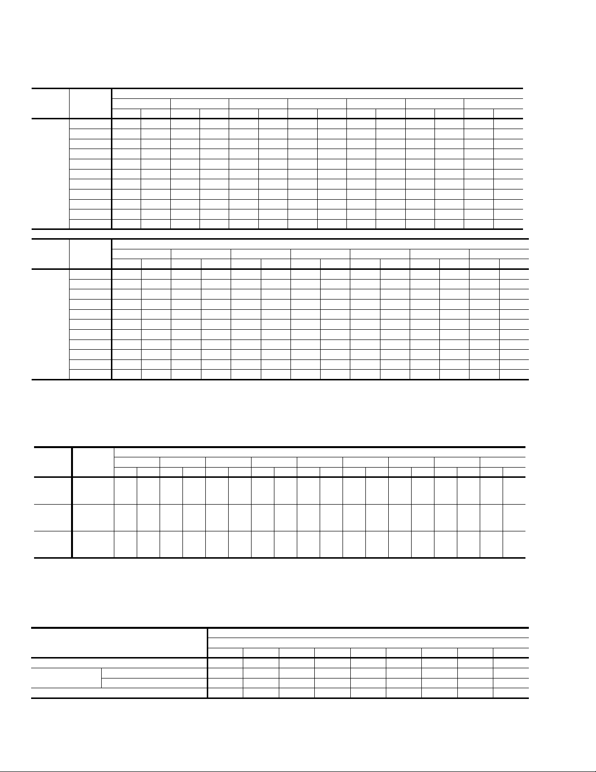
511.06-N5Y
TABLE 5
- SUPPLY AIR PERFORMANCE - 5 Ton
w/Belt-Drive Blower
5 TON - SIDE DUCT CONNECTIONS @ 230/460/575 Volts
MODEL
BHN
AIR FLOW
CFM
0.20 0.30 0.40 0.50 0.60 0.70 0.80
RPM Watts RPM Watts RPM Watts RPM Watts RPM Watts RPM Watts RPM Watts
2500 1059 1560 1077 1590 1095 1630 1114 1650 1134 1660 1158 1685 1181 1720
2400 1032 1405 1054 1470 1074 1525 1094 1560 1116 1595 1140 1620 1167 1640
2300 1005 1260 1024 1275 1049 1370 1069 1440 1090 1475 1116 1505 1142 1535
2200 980 1160 1002 1170 1022 1190 1044 1250 1066 1350 1090 1410 1117 1440
2100 930 1060 957 1070 983 1080 1010 1100 1039 1160 1064 1260 1092 1340
060
2000 877 950 908 975 941 1000 976 1020 1009 1050 1040 1100 1070 1225
1900 - - - - 894 885 940 940 980 980 1014 1020 1047 1095
1800 - - - - 855 815 903 860 950 905 988 940 1022 970
1700 - - - - - - 884 815 925 850 964 880 1001 910
1600 - - - - - - 864 770 908 805 948 835 987 870
1500 - - - - - - - - 882 740 926 780 965 830
MODEL
BCH
AIR FLOW
CFM
0.90 1.00 1.10 1.20 1.30 1.40 1.50
RPM Watts RPM Watts RPM Watts RPM Watts RPM Watts RPM Watts RPM Watts
2500 - - - - - - - - -----2400 1193 1665 - - - - - - -----2300 1170 1580 1202 1620 - - - - -----2200 1148 1480 1180 1530 - - - - -----2100 1121 1385 1155 1425 1190 1475 - - ------
060
2000 1100 1285 1133 1340 1169 1385 1205 1445 -----1900 1079 1180 1110 1240 1143 1280 1178 1330 1222 1375 ---1800 1058 1060 1090 1135 1122 1190 1158 1240 1196 1295 ---1700 1035 960 1071 1030 1103 1100 1134 1140 1164 1175 1197 1205 - 1600 1020 900 1056 965 1088 1035 1118 1065 1145 1105 1170 1130 1198 1150
1500 1004 860 1038 880 1070 925 1101 980 1130 1045 1158 1075 1184 1110
NOTE: FOR 208 V O LTS, MULTIPLY VALUES B Y 0.95.
*INCLUDES ALLOWANCES FOR A WET INDOOR COIL AND 1" FILTERS. REFER TO TABLE 7 FOR RESISTANCE VAL UES ON APPLICATIONS OTHER THAN HEAT PUMP UNITS
WITH SIDE DUCT AIRFLOWS.
Available External Static Pressure - IWG*
Available External Static Pressure - IWG*
TABLE 6
- SUPPLY AIR PERFORMANCE - 3, 4 & 5 Ton
w/Direct-Drive Blower
230 / 460 / 575 VOLTS - SIDE DUCT APPLICATIONS
MODEL
BCH
036
048
060
NOTE: FOR 208 V O LTS, MULTIPLY VALUES B Y 0.95.
*INCLUDES ALLOWANCES FOR A WET INDOOR COIL AND 1" FILTERS. REFER T O TABLE 7 FOR RESISTANCE VALUES ON APPLICATIONS OTHER THAN HEAT PUMP UNITS
WITH SIDE DUCT AIRFLOWS.
TABLE 7
MOTOR
SPEED
HI
MED
LOW
HI
MED
LOW
HI
MED
LOW
0.20 0.30 0.40 0.50 0.60 0.70 0.80 0.90 1.00
CFM Watts CFM Watts CFM Watts CFM Watts CFM Watts CFM Watts CFM Watts CFM Watts CFM Watts
-
-
-
1660
1470
-
1810
1635
-
2390
2270
850
750
910
810
1350
1320
1630
1440
-
-
1780
1610
-
-
2350
2230
- STATIC RESISTANCES*
820
725
880
780
1300
1270
-
-
1590
1410
2000
-
1740
1580
2500
-
2300
2190
EXTERNAL STATIC PRESSURE DROP
DESCRIPTION
Economizer
Electric Heaters
Bottom Duct Connections
1Deduct these resistance values from the available external static pressure shown in the respective Blower Performance T able.
2
The pressure thru the economizer is greater for 100% outdoor air than for 100% return air. If the resistance of the return air duct system is less than 0.25 IWG, the unit will deliver less CFM
during full economizer operation.
1, 2
1
5 - 15 KW 0.04 0.05 0.06 0.07 0.08 0.10 0.12 0.14 0.16
20 - 30 KW 0.06 0.07 0.08 0.09 0.11 0.13 0.15 0.17 0.20
1
1000 1200 1400 1600 1800 2000 2200 2400 2600
0.07 0.08 0.09 0.11 0.13 0.15 0.17 0.20 0.23
0.06 0.07 0.08 0.09 0.10 0.11 0.12 0.14 0.16
Available External Static Pressure - IWG*
780
700
1010
850
760
1400
1255
1220
-
1500
750
1550
1370
1950
1700
1555
2420
2245
2145
675
975
825
740
1350
1210
1170
1330
1905
1665
1540
2340
2190
2090
720
650
945
800
730
1300
1165
1110
1450
1290
1840
1620
1510
2260
2130
2030
1600
795
1665
825
1720
RESISTANCE, IWG
CFM
765
690
625
910
775
715
1250
1120
1070
1540
1400
1250
1770
1560
1460
2160
2065
1960
735
665
610
825
740
690
1190
1075
1020
1490
1360
1220
1660
1480
1400
2060
1990
1890
700
650
600
825
700
660
1135
1030
970
1380
1270
1130
1530
1390
1300
1925
1900
1810
670
610
560
775
660
615
1065
970
920
10 Unitary Products Group
Page 11
511.06-N5Y
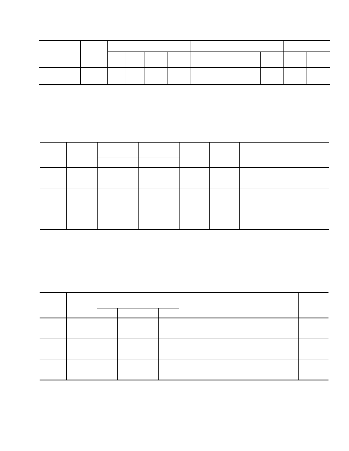
TABLE 8
- MOTOR AND DRIVE DATA w/Belt-Drive Blower
MOTOR*
FRAME
SIZE
MODEL
BLOWER
RANGE
(RPM)
HP RPM
SERVICE
FACTOR
ADJUSTABLE
MOTOR PULLEY
PITCH
DIA.
(in.)
BORE
(in.)
FIXED
BLOWER PULLEY
PITCH
DIA.
(in.)
BORE
(in.)
BELT
PITCH
LENGTH
(in.)
BCH 036 790 - 1120 1-1/2 1725 56 1.15 2.4 - 3.4 7/8 5.7 1 37.3 A36
BCH 048 790 - 1120 1-1/2 1725 56 1.15 2.4 - 3.4 7/8 5.7 1 37.3 A36
BCH 060 850 - 1220 1-1/2 1725 56 1.15 2.4 - 3.4 7/8 5.2 1 37.3 A36
*All motors have soli d ba ses an d ar e inh er en tly pr ot ect ed . These motors can be selected to oper a te into the i r service f a cto r be cau se th e y ar e loca te d in th e mo ving air, upstre am of an y
heating device.
TABLE 9
MODEL
- ELECTRICAL DATA
BCH
POWER
SUPPLY
MIN. MAX. RLA LRA
208/230-1-60
036
208/230-3-60
460-3-60
575-3-60
208/230-1-60
048
208/230-3-60
460-3-60
575-3-60
208/230-1-60
060
208/230-3-60
460-3-60
575-3-60
NOTES: 1. Rated in accordance wtih ARI Standard 110, utilizatin range "A".
2. Dual element, time delay type.
w/Direct-Drive Blower Motor
VOLT AGE
LIMITATIONS
(SEE NOTE 1)
187
187
414
518
187
187
414
518
187
187
414
518
253
253
504
630
253
253
504
630
253
253
504
630
COMPRESSOR
19.0
11.9
5.9
4.8
23.1
14.7
7.7
6.4
32.1
19.3
10.0
7.9
105
85
42
34
105
130
64
52
169
137
62
50
OUTDOOR
FAN
MOTOR,
FLA
1.7
1.7
1.0
1.0
2.3
2.3
1.4
1.4
2.3
2.3
1.4
1.4
SUPPLY
AIR
BLOWER
MOTOR,
FLA
4.4
4.4
2.2
2.2
5.0
5.0
2.2
2.2
6.6
6.6
3.3
3.3
MINIMUM
CIRCUIT
AMPACITY
29.9
21.0
10.6
10.2
36.1
25.7
13.2
11.6
49.0
33.0
17.2
14.6
MAX.
FUSE
SIZE,
(SEE NOTE 2)
AMPS
45
30
15
15
50
40
20
15
80
50
25
20
HACR
BREAKER
AMPS
DESIG-
NATION
MAX.
SIZE,
45
30
15
15
50
40
20
15
80
50
25
20
TABLE 10
MODEL
BCH
- ELECTRICAL DATA
POWER
SUPPLY
LIMITATIONS
(SEE NOTE 1)
MIN. MAX. RLA LRA
208/230-1-60
036
208/230-3-60
460-3-60
575-3-60
208/230-1-60
048
208/230-3-60
460-3-60
575-3-60
208/230-1-60
060
208/230-3-60
460-3-60
575-3-60
NOTES: 1. Utilizatio n Range “A” in accordance with ARI Standard 110.
2. Dual element, time delay type.
187
187
414
518
187
187
414
518
187
187
414
518
w/Belt-Drive Blower Motor
VOLT AGE
253
253
504
630
253
253
504
630
253
253
504
630
COMPRESSOR
19.0
11.9
5.9
4.8
23.1
14.7
7.7
6.4
32.1
19.3
10.0
7.9
105
85
42
34
105
130
64
52
169
137
62
50
OUTDOOR
FAN
MOTOR,
FLA
1.7
1.7
1.0
1.0
2.3
2.3
1.4
1.4
2.3
2.3
1.4
1.4
SUPPLY
AIR
BLOWER
MOTOR,
FLA
5.3
5.3
3.1
3.1
8.6
5.2
2.6
2.0
8.6
6.0
3.0
2.4
MINIMUM
CIRCUIT
AMPACITY
34.8
21.9
11.5
11.1
39.7
25.9
13.6
11.4
51.0
32.4
16.9
13.7
MAX.
FUSE
SIZE,
(SEE NOTE 2)
AMPS
45
30
15
15
50
40
20
15
80
50
25
20
MAX.
HACR
BREAKER
SIZE,
AMPS
45
30
15
15
50
40
20
15
80
50
25
20
Unitary Products Group 11
Page 12
511.06-N5Y
OPERATION
COOLING SYSTEM
The unit has an air-co oled cond enser and i s factory- charged
with Refrigerant-22.
The compressor is hermetically sealed, internally sprung,
mounted on spring isolators and inherently (internally)
protected. If there is an abnormal temperature rise in the
compressor, the protector will open to shut down the
compressor.
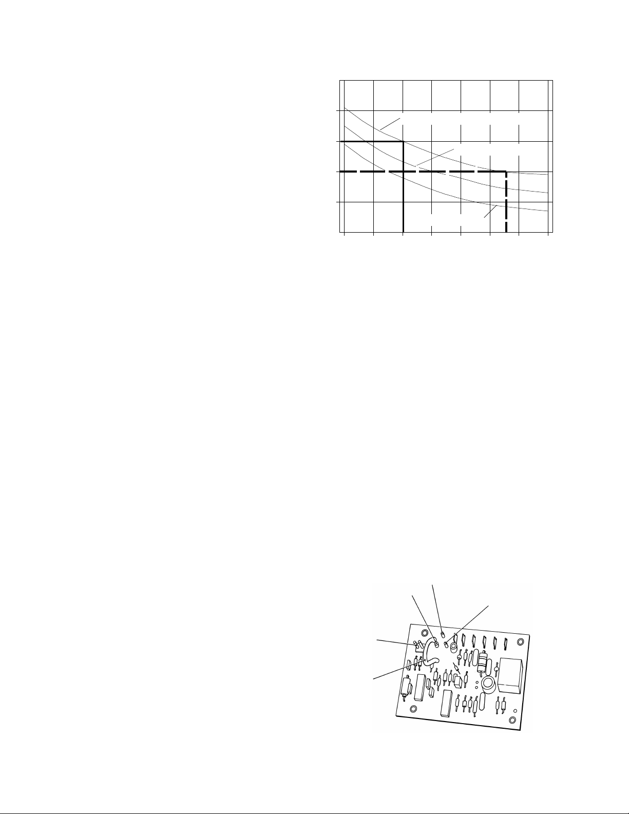
250
200
150
100
T3 - 110 Minute Setting (Factory Set Point)
T2 - 80 Minute Setting
PRELIMINARY OP ERATION COOLING
After the installation has been completed, the crankcase heater
of the compressor must be energized f or at least 4 hours bef ore
starting the unit. After this initial warm-up, the compressor
should be given three false starts (energized just long enou gh
to make a few revolutions) with a 5 minute delay between each
start before being put into full time service.
NOTE: Prior to each co oling season, the crankcase he ater
must be energiz ed at least 10 ho urs befo re the syst em
is put into operation.
COOLING SEQUENCE OF OPERATION
When the thermost at call s f or cool ing, the comp ressor a nd the
outdoor f an mo to r w ill b e e ne r gi z e d t hro ug h t erminal "Y1 " a nd
the supply air blower motor will be ene rgi z e d through terminal
"G" (if the fan switch on the subbase is set in the "AUTO"
position). The supply air blower motor will run continuously if
the fan switch is set in the "ON" pos it io n.
The reversing valve is energized th ru th e "O" cir cui t when the
subbase is in the cooling mode.
HEATING SEQUENCE OF OPERATION
The following sequence of operation is based on using a
standard Y ORK he at pump thermostat w ith two heatin g stages.
FIRST STAGE HEAT
When the thermostat calls for heating, the compressor and the
outdoor f an mo to r w ill b e e ne r gi z e d t hro ug h t erminal "Y1 " a nd
the supply air blower motor will be ene rgi z e d through terminal
"G" (if the fan switch on the subbase is set in the "AUTO"
position). The supply air blower motor will run continuously if
the fan switch is set in the "ON" pos it io n.
50
T1 - 50 Minute Setting
0
TIME BETWEEN DEFROST CYCLES, MINUTES
-10
FIG. 7
- DEFROST INITIATION TIMES
0
20
10
OUTDOOR AMBIENT, DEG. F
40 50
30
EXAMPLE: If t he ti me is factory set on pin T-3 (110 minutes at
35°F outdoor) and the out door temper ature climbs to 45°F, the
time initiation cycle will decreas e to every 100 minut es.
If the outdoor temperature drops to 10°F where ice is less likely
to form, the 110 minute interval will extend to every 150
minutes.
Two r equir ements must be m et before a def rost c ycle ca n be
initiated.
1. The defrost time cycle must be complete.
2. The liquid line te mp erature must be l es s t ha n 2 8°F.
Defrost will terminate when the liquid line sensor reaches 55°F
or after 10 minutes .
The defrost time cycle will restart 10 minutes after the start of
the defrost cycle even though the liquid sensor terminated
defrost after 3 minutes.
During troubleshooting, the defrost time can be reduced to 20
seconds by sh orting out the SW1 tes t pegs on the module . The
pegs are 1 /2" long, 3/ 16" apar t and are m ounted on a whit e
base. See Figure 8.
60
SECOND STAGE HEAT
If compressor operation can not satisfy the heating
requirements, second stage heat will energize supplemental
T2 - 80 MINUTE SETTING
T3 - 110 MINUTE SETTING
(Factory Set Point)
T1 - 50 MINUTE SETTING
electric heat (if supplied) thru the "W1" circuit.
DEFROST SEQUENCE OF OPERATION
The BCH has a un ique “ambient modif ied” time-temperature
defrost control that automatically adjusts to changes in the
outdoor temperature. The defrost control will shorten the
defrost in itiation time pe riods above 35°F and will extend the
defrost initiation time periods below 35°F. The control is factory
set to defro st at 110 m inute s (T3) , but it can be field adj us ted
SHORTING PEGS TO
OVERRIDE TIMER
FOR SERVICE
MOVABLE JUMPER
WIRE TO CHANGE
DEFROST TIMER
to defrost a t 80 m inu te s ( T2 ) o r 5 0 mi nut es ( T1) in a rea s wit h
high humidity.
The curve in Figure 7 shows how defrost initiation times are
automatically compensated for changes in outdoor
temperature.
12 Unitary Products Group
FIG. 8
- AMBIENT MODIFIED TIME/TEMPERATURE
CONTROL
Page 13
LOCKOUT CONTROL
Any one of four conditions will put the system into a lock-out
condition durin g th e he at ing or cooling mode:
1.
The discharge line temperature reaches 255°F (215°F
reset) or,
2. The discharge pressure reaches 398 PSIG (310 PSIG
reset) or,
3.
The suction line f ree z e stat equals 26°F (38°F reset) or ,
4. The low-pressure cut-out equals 7 PSIG (22 PSIG reset).
A lock-out will energize the emergency heat light on the
thermostat and the red LED ligh t on the unit relay board. T urning
the thermostat switch to "Off" then back to "On", will reset the
system.
NOTICE T O O WNER:
If a lockout occurs, ch eck for the following problems b efore
calling a serviceman:
1. Dirty filters.
2. Snow accumulation.
3. Leaf or debris blockage.
After eliminating the problem, attempt to restart the system as
follows:
turn the system s witch on the thermostat to its "OFF " position
•
for 10 seconds.
turn it back to its origi na l po si ti on .
•
If the unit doesn’ t st art, call a se rviceman.
NOTE: Models with an anti-recycle accessory will have a
5-minute delay before starting.
CHECKING SUPPLY AIR CFM
The speed of the supply air blower will depend on the required
CFM, the unit acc essories and th e static resistan ces of both
the supply and the return air duct systems. With this
information, the speed for the supply air blower can be
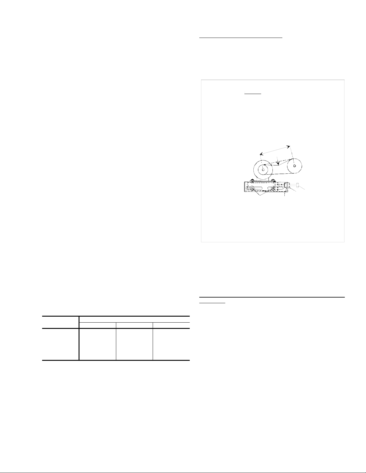
TABLE 11
*Pulley can be adjusted in half-turn increments.
determined from the b lo wer p erf ormance and st atic re sistan ce
data on T ab les 4 through 7.
Knowing the required blower RPM and the blower motor HP,
the speed settin g for the supply air mo tor can be determined.
The setting (turns open) for the optional belt-drive supply air
pulley can be determined from Table 11 .
- BELT-DRIVE SUPPLY AIR
MOTOR PULLEY ADJUSTMENT
TURNS
OPEN*
5
4
3
2
1
0
BLOWER DRIVE RANGE (RPM)
3 TON 4 TON 5 TON
780
842
904
966
1028
1090
790
856
922
988
1054
1120
850
924
998
1072
1246
1220
511.06-N5Y
OPTIONAL BELT-DRIVE BLOWER
All units wit h belt-driv e b lowers hav e sin gle spee d motors . T he
variable pitch pu lley on the blower motor can be adjust ed to
obtain the desired supply air CFM. Refer to Table 8 for blower
motor drive data. The tension on the belts should be adjusted
as shown in Figure 9.
Procedure for adjusting belt tension:
1. Loosen nut (D) from the motor mount.
2. Never loosen nuts (C) from each other while loosening nut (D).
3. Adjust the tension by turning bolt (B).
4. Do not loosen the four nuts (top and bottom) (A); unless additional tensioning
distance is required; immediately re-tighten these bolts if loosened.
5. Use a belt tension checker to apply a perpendicular force to one belt at the
midpoint of the span as shown. The deflection force should be applied
until a specific deflection distance of 4mm (5/32")is obtained. To determine
the deflection distance from normal position, use a straight edge from
sheave to sheave as a reference line. The recommended deflection force
is as follows:
Tension new belts at the max. deflection force recommended for the belt
section. Check the belt tension at least two times during the first 24 hours of
operation. Any re-tensioning should fall between the min. and max.
deflection force values.
6. After adjusting, re-tighten nut (D) against the motor mount taking care not
to loosen nuts (C).
FIG. 9
- BELT ADJUSTMENT
CAUTION
SPAN LENGTH
(A)
DEFL FORCE
(C)*
(B)
(D)
* NEVER LOOSEN
Start the supply air blower motor. Adjust the resistances in both
the supply an d the retur n air duct system s to balan ce the air
distribution throughout the conditioned space. The job
specifications may require that this balancing be done by
someone other tha n the equipment inst al le r.
T o check the supply air CFM after the initial balancing has been
completed:
1.
Remove the (tw o)
5
⁄
" dot plugs from the hole s loc ated on
16
the filter access panel side of the unit.
2. Insert at least 8" of 1/ 4 inch tub ing into each of these h oles
for sufficient pene tration into the air flow on both side s of
the indoor coil.
NOTE: The tubes must be inserted and held in a position
perpendicular to the air flow so that velocity pressure
will not affect the static pres su re rea dings.
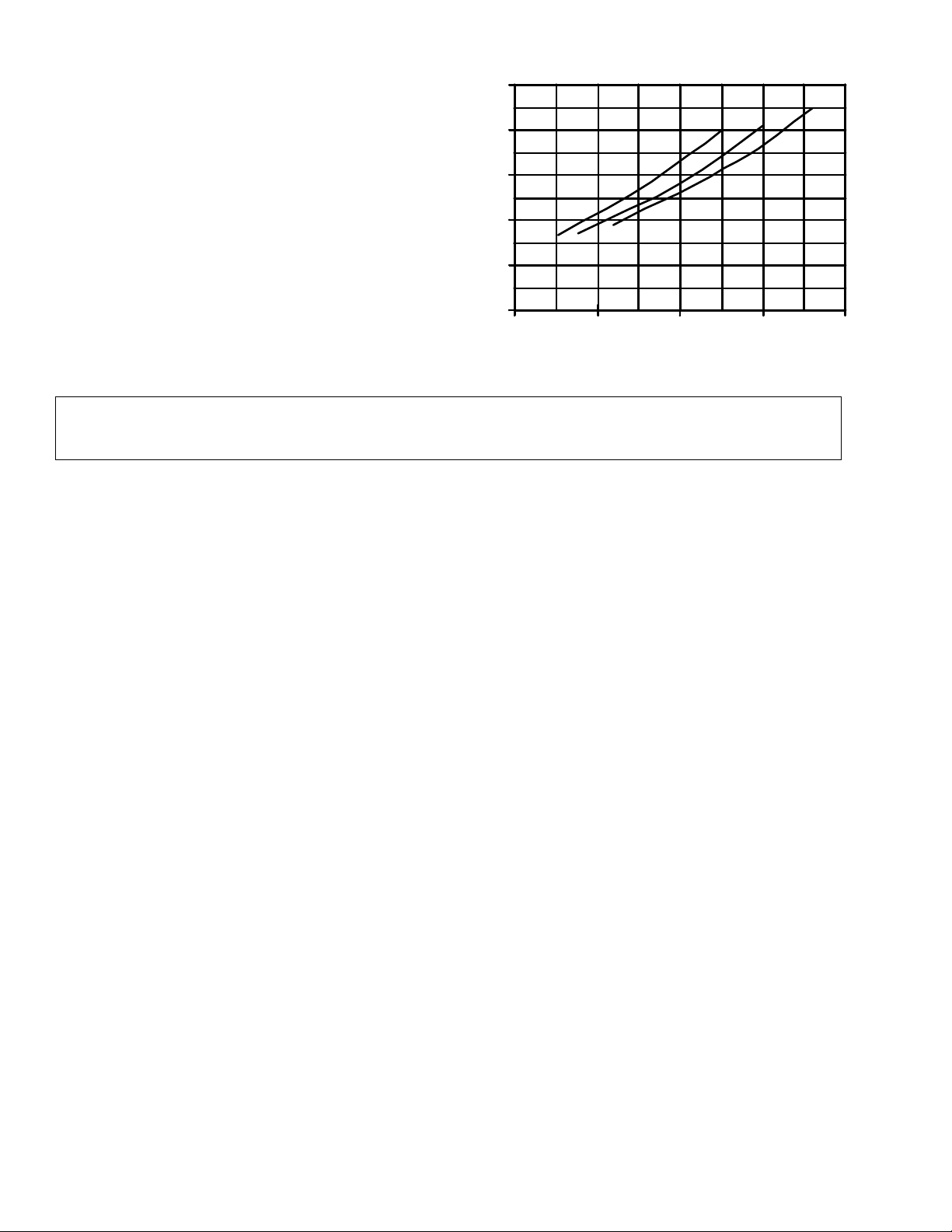
3. Using an inclined manometer, determine the pressure drop
across a d ry indoor c oil. Since the mo isture on an indoor
coil may vary greatly, measuring the pressure drop across
a wet coil under field condi tions would be inac curate. To
ensure a dry coil, the com pressors should be de-energiz ed
while the test is being run.
4. Knowing the pressure drop across a dry coil, the actual CFM
through the unit can be determined from the curve in Figure 10.
Unitary Products Group 13
Page 14
511.06-N5Y
WARNI NG:Failure to prope rly adjust th e total syst em air quan -
tity can result in poor system performance.
After readings hav e been obta ined, remo ve th e tubes and se al
the drilled holes in the side panels. 5/16" dot plugs (P/N
029-13880) are available through normal parts ordering
procedures.
0.5
0.4
0.3
036
048
060
NOTE: DE-ENERGIZE THE COMPRESSORS BEFORE
TAKING ANY TEST MEASUREMENTS TO ENSURE
A DRY INDOOR COIL.
0.2
PRESSURE DROP (IWG)
0.1
0
1000 1500 2000 2500 3000
FIG. 10
- PRESSURE DROP ACROSS A DRY INDOOR
NOMINAL CFM
COIL VS. SUPPLY AIR CFM
SECURE OWNER’S APPRO VAL: When the system is functioning properly, secure the owner’s approval. Show him the location
of all disconnect switches and the thermostat. Teach him how to start and stop the unit and how to adjust temperature settings
within the limi tations of the system.
MAINTENANCE
NORMAL MAINTENANCE
CAUTION: Prior to any of th e following maintenance proce-
dures, shut off all power to the unit to prevent
personal injury.
FILTERS - Inspect once a month. Replace disposable or clean
permanent type as necessary. DO NOT replace permanent
type with disposable.
MOTORS - Indoor fan and outdoor fan motors are permanently
lubricated and requi re no mai nt en ance.
OUTDOOR COIL - Dirt should not be allowed to accumulate
on the outdoor coil surface or other par ts in the air circuit.
Cleaning sh ould be as often a s nec es sar y to kee p coi l cle an.
Use a brush, vacuum cleaner attachment, or other suitable
means. If water is used to clean coil, be sure power to the unit
is shut off prior to cleaning.
NOTE: Exercise care when cleaning the coil so that the coil
fins are not damage d.
Do not permit the outdoor air discharge to be ob-
structed by overhanging structures of shrubs.
14 Unitary Products Group
Page 15

511.06-N5Y
Unitary Products Group 15
Page 16

208/230/460 V O LT
MODELS ONLY
Unitary Products Group
5005 York Drive, Norman, Oklahoma 73069
Subject to change without notice. Printed in U.S.A.
Copyright by York International Corporation 2000. All Rights Reserved.
208/230/575 VOLT
MODELS ONLY
511.06-N5Y
 Loading...