


York 122, 152, YLCC-h, YLCC 42, YLCC 62 User Manual
...Heat pumps and water chillers, YLCC-H and YLCC-42, 62, 82, 102, 122 and 152 (R-407C) with centrifugal fans For indoor installation
Ref.: TYLC-CE2
Technical information
ACCORDING TO ISO 9001 STANDARDS
ER-0028/1991
ACCORDING TO ISO 14001 STANDARDS
CGM-97/013

Index
|
Page |
General description |
5 |
|
|
- Nomenclature |
5 |
- General characteristics |
5 |
Technical specifications |
5 |
|
|
- Mechanical specifications |
5 - 6 |
- Controls |
6 |
- Accessories |
6 - 7 |
- Physical data and electrical characteristics |
8 - 9 |
- Limits of use |
10 |
- Limits of use, YLCC |
10 |
- Limits of use, YLCC-H |
10 |
- Test conditions |
10 |
- Nominal flows, cooling only |
10 |
- Nominal flows, heat pump |
10 |
- Cooling capacities |
11 - 14 |
- Heating capacities |
15 - 16 |
- Hydraulic circuit flow/pressure |
|
characteristics of YLCC and YLCC-H units |
17 - 18 |
- Fan performances |
19 |
- Correcting factors |
20 |
- Factors with water and glycol |
20 |
Installation instructions |
21 |
|
|
- General information |
21 |
- Inspection |
21 |
- Environmental protection |
21 |
- Warning signs |
21 |
- Transportation |
21 |
- Clearances |
22 |
- Drainage |
22 |
- Locating and securing the unit |
22 |
- Hydraulic connections |
23 |
- Hydro kits GH |
24 |
- Circulating pump |
24 |
- Flow switch |
24 |
- Application on YLCC/YLCC-H units |
24 |
- Wiring |
25 |
Operating and start-up instructions |
26 |
|
|
- YLCC/YLCC-H control system |
26 |
- Standard components |
26 |
- Interconnecting diagram |
27 |
|
Page |
- Identification of system intakes and outlets |
28 |
Accessories |
28 |
|
|
- Remote terminal |
28 |
- Programmable key |
29 |
- Unit addressing |
30 |
- Unit control |
30 |
- Display |
30 |
- Unit status |
30 |
- Keyboard |
30 |
- Activation/deactivation of "COOL" function |
30 |
- Activation/deactivation of "HEAT" function |
30 |
- Access to "DIRECT" parameters |
30 |
- Access to "USER" parameters |
30 |
- Access to "FACTORY" parameters |
31 |
- Deactivation of buzzer |
31 |
- Alarm reset |
31 |
- Forced defrost |
31 |
- Clearing hour counters |
31 |
- Installation of default parameters |
31 |
- Adjusting display contrast |
31 |
- Summary of keyboard functions |
31 |
- Operation of ser point |
32 |
- Compressors |
32 |
- Defrost cycle |
33 |
- Pump operation |
33 |
- Single-phase axial or centrifugal fans operation with |
|
speed control |
34 |
- Alarms and messages |
35 |
- Yellow and green LEDs on base plate |
36 |
- Probe calibration |
36 |
- Remote ON/OFF |
36 |
- Remote COOL/HEAT |
36 |
- Protection of "DIRECT" parameters |
36 |
- Buzzer configuration |
36 |
Operation |
36 |
|
|
- Cooling cycle YLCC |
36 |
- Cooling cycle YLCC-H |
37 |
- Heating cycle YLCC-H |
37 |
General dimensions |
38 - 42 |
|
|
Wiring diagrams |
43 - 62 |
|
|
3
General description
The YLCC water chillers and YLCC-H heat pumps are supplied factory-assembled and with all refrigerant piping and interconnecting wiring ready for installation at the job site. After assembly, the water chillers go through a water test. Possible leaks are also checked once the refrigerant is charged.
The units are made of galvanized steel with anticorrosive nuts and bolts. The panels can be removed for access to internal components. The outer galvanized steel parts are painted with oven-dried enamel (RAL 9002).
Throughout the manufacturing process, all our products follow a quality control process in accordance with the ISO 9001 standard, which is also demanded from the acquired components.The PED pressure equipment directive is also applied. The water chillers or air-water type heat pumps are designed to be installed in air conditioning systems or industrial processes that require cold (or hot) water or water with glycol. Designed for indoor installation.
Nomenclature
YORK unit
Liquid chiller
Centrifugal fan
Heat pump
Model
 Vertical air discharge
Y LC C H 42 V
General characteristics
The main characteristics of these units are:
-Operating test at factory.
-Ready for job site installation.
-Electronic control of water temperature.
-Two independent circuits (2 stages up to 102) (4 stages 122 and 152).
-Scroll compressors.
-Centrifugal fan (horizontal or vertical air discharge).
-Coaxial exchanger.
-R-407C refrigerant.
-Hydro kit (option).
The accessibility of all components and control system allows quick installation and start-up, as well as trouble-free maintenance.
Technical specifications
Mechanical specifications
Casing
Made of zinc-coated aluminium steel sheeting, finished with oven-polymerised powdered paint, colour RAL 9002. it may be installed directly outdoors.
Their extraordinary protection against corrosion, along with their heavy duty internal structure, make up an extremely robust and resistant unit.
Compressor
The hermetic Scroll compressor is protected internally. Starting will be direct on line. With electronic control. The crankcase heater is activated when the compressor is inoperative. Mounted on anti-vibratory supports.
Evaporator (water)
Coaxial type exchanger, of a large transmission surface, made of finned tubing. Insulated externally.
Maximum operating pressure is 25 bar on the refrigerant side, and 10 bar on the water side.
Condenser (air)
Of a large surface. Made of copper tubing in staggered rows, mechanically expanded within high performance aluminium fins. Maximum operating pressure of the coil is 28 bar (standard unit).
Control of refrigerant to the exchangers
Refrigerant feed is carried out by means of an expansion valve with external pressure equalizer (reversible on heat pump models).
Refrigerant
The units are supplied with an optimum R-407C refrigerant charge for correct operation and maximum output under different working conditions.
Cooling circuit
Made of welded copper tubing and equipped with 1/4" SAE connections on the high and low pressure sides.
This product has been designed, manufactured and tested in accordance with the strictest European safety regulations. Includes the following components:
-Suction accumulator (heat pump only).
-Filter-dryer.
-Expansion valve.
-4-way valve (heat pump only).
-Liquid sight glass.
-Liquid accumulator (heat pump only).
-Automatic high and low pressure switches.
Electric and control panel
The electric and control components are factory-controlled,
5
connected and tested.The electric box has a door with a blocking mechanism and contains the compressor and fan contactors, fuses and electrical protection. Also has IP44 protection.
Centrifugal fans
Transmission is by belts and removable core pulleys. The motors are mounted on tensing bases fastened directly to the fan casing.
Two versions are available: with horizontal or vertical air discharge
Controls
So as to achieve maximum energy savings, perfect operation of the equipment and prolong the useful life of same, the YLCC water chillers or heat pump units are equipped with the following controls:
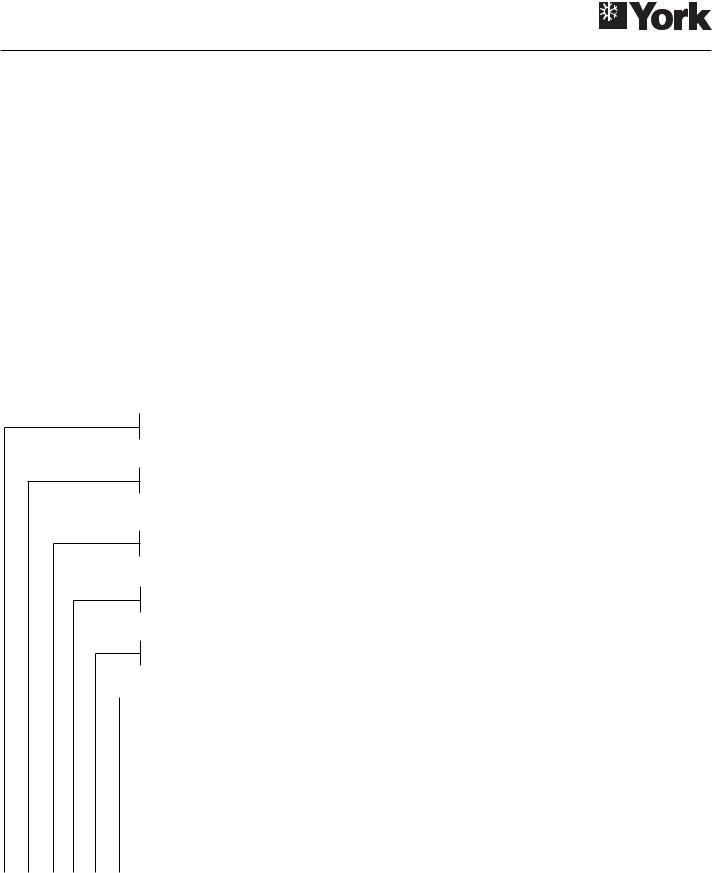
-Electronic thermostat that controls cold water return temperature.
-Electronic antifreeze thermostat.
-High pressure switch, 31 bar.
-Low pressure switch, 2 bar.
-Stage rotation (included in the thermostat).
-Remote terminal unit (optional).
-Timed start.
-Remote control.
Compatible with the following units:
GH200 |
for size 42 |
||
GH260 |
for sizes 62 and 82 |
||
GH600S |
for sizes 102 and 122 |
||
GH600P |
for size 152 |
||
|
|
|
|
|
|
|
|
|
|
|
|
|
|
|
|
|
|
|
|
|
|
|
|
comp |
PRG |
|
|
mute |
|
|
|
clear |
|
SEL |
chillerµ |
|
|
|
x 100 |
|
|
Accessories
Hydro kit GH
Includes: Buffer tank, automatic air purger, pressure gauge, automatic 1.5 bar filling valve, expansion vessel, pump, flow switch, drain valve, safety valve and electronic board for interconnection. Available in 200, 260 and 600 litre capacities. There are two versions of GH600: GH600S and GH600P.
DI buffer tanks
Cylindrical shape and in vertical position. Available in 200, 260 and 600 litre capacities.
Low ambient kit (factory-mounted, optional)
This accessory allows operation of the unit when the condensing outdoor air temperature is below 10° C.
General information
This accessory controls condensing pressure in the winter cycle by varying air flow through the outdoor coils. This flow variation keeps condensing pressure constant when outdoor temperatures are low.
Operation
By means of the pressure detected through the analogical pressure switches installed in the cooling circuit, and carrying out the appropriate calculations as programmed, this control generates an analogical signal that opens the dampers to maintain the condensing pressure previously programmed as the set point.
6
Anti-vibratory supports
Whenever a maximum reduction of vibration and noise generated by the unit is required, a set of steel spring anti-vibratory supports can be used.These should be installed between the supporting frame of the unit and the base or floor where same is to be located. This base should be solid and sized in accordance with the weight to be supported. 12MA bolts are use to secure the supports to the base of the frame.This antivibratory support accessory for YLCC-42/62 includes 4 springs, whereas forYLCC-82/102/122/152 it includes 6.These spring supports should be distributed and secured by means of the corresponding holes drilled in the chiller base, the location of which is detailed in General Dimensions.
12 MA
94 (MAX) |
82+3 (MIN) |
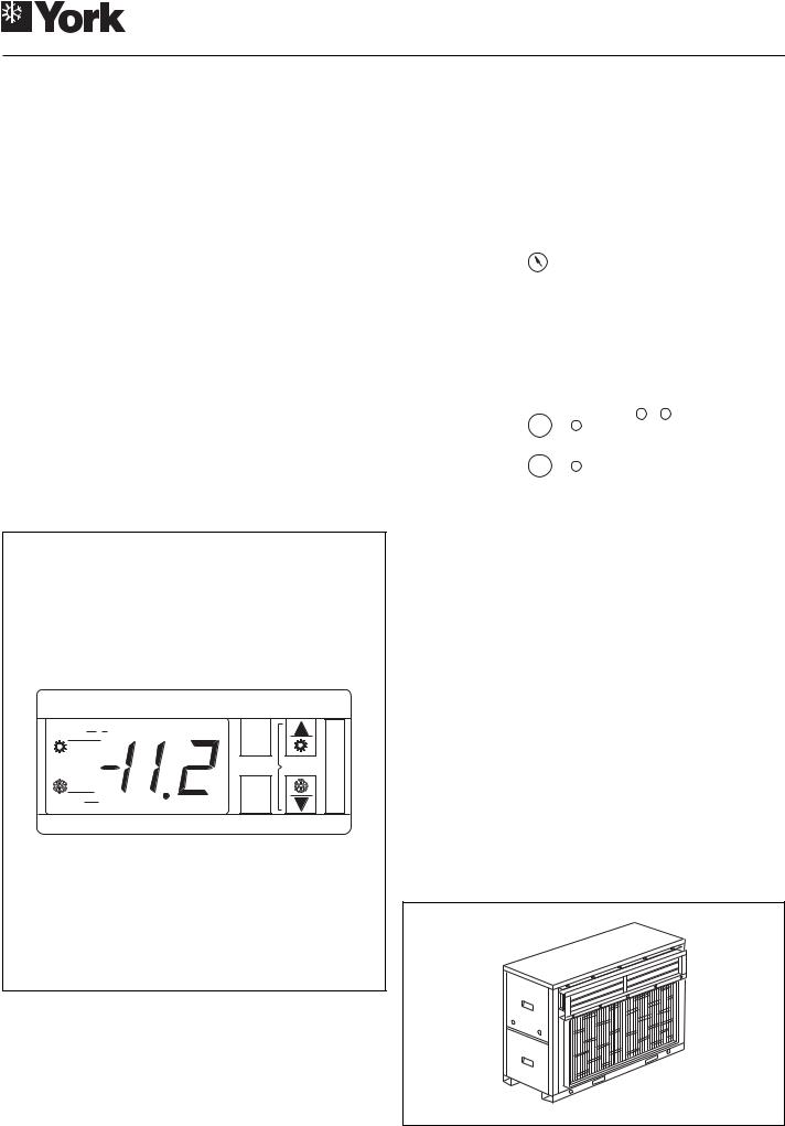
Remote control (accessory)
For access and control by means of the buttons and LEDs available. Allows selecting the cool, heat and OFF functions, and the red LED indicates any failure.
Can be installed at a maximum distance of 50 m.The remote terminal should be connected to the unit with a 7 x 0,35 mm2 cable.
Flow switch (optional accessory)
Flow switch
Switch with a 1" MPT thread, adequate for a Design Operating Pressure of 10 bar hand so as to protect the equipment against water flow drops. This switch, or an equivalent, is required for the site installation of each unit (obligatory).
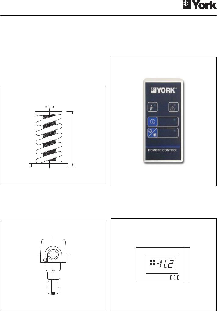
Remote terminal
For total access and control of the system by means of the display, buttons and LEDs. Allows selecting cool, heat and off functions. Can also modify operating parameters and monitor the system. Can be installed at a distance of 150 m.
7

Physical data and electrical characteristics
Cooling only
Model |
|
|
|
YLCC |
YLCC |
YLCC |
YLCC |
YLCC |
YLCC |
|
|
|
|
42/42V |
62/62V |
82/82V |
102/102V |
122/122V |
152/152V |
||
|
|
|
|
|||||||
Cooling capacity |
|
kW |
40.2 |
64 |
72.5 |
96.1 |
116 |
145 |
||
|
|
|
|
|
|
|
|
|
|
|
|
Amount |
|
|
2 |
2 |
2 |
2 |
2 |
2 |
|
|
|
|
|
|
|
|
|
|
||
|
Type |
|
|
Scroll |
Scroll |
Scroll |
Scroll |
Tandem-Scroll Tandem-Scroll |
||
|
|
|
|
|
|
|
|
|
|
|
|
Nominal power (a) |
|
kW |
8.3 (x2) |
11.7 (x2) |
13.7 (x2) |
19.1 (x2) |
27.6 (x2) |
27,9 (x2) |
|
|
|
|
|
|
|
|
|
|||
Compressor |
Power supply |
V.ph.Hz |
|
|
400.3.50 |
|
|
|||
|
|
|
|
|
|
|
|
|
||
Compres. consump. in cool A |
16.2 (x2) |
21.3 (x2) |
26.3 (x2) |
34 (x2) |
47.6 (x2) |
50,9 |
||||
|
||||||||||
|
|
|
|
|
|
|
|
|
|
|
|
Starting current |
|
A |
130 |
135 |
175 |
215 |
135 |
175 |
|
|
|
|
|
|
|
|
|
|
|
|
|
Oil charge |
|
l |
3.25 |
3.3 |
6.6 |
8 |
6.6 |
6.6 |
|
|
|
|
|
|
|
|
|
|
||
|
Oil type |
|
|
|
|
Polyolester ISO 32 |
|
|
||
|
|
|
|
|
|
|
|
|
|
|
|
Amount |
|
|
2 |
2 |
2 |
2 |
2 |
2 |
|
|
|
|
|
|
|
|
|
|
|
|
|
Total nom. air flow |
|
m3/h |
13 268 |
20 122 |
23 304 |
28 834 |
33 247 |
38 312 |
|
|
|
|
|
|
|
|
|
|
|
|
|
Fan size |
|
mm |
12-12 |
15-15 |
15-15 |
18-18 |
18-18 |
18-18 |
|
|
|
|
|
|
|
|
|
|
|
|
|
Power (a) |
|
W |
1 280 (x2) |
2 407 (x2) |
2 648 (x2) |
3 549 (x2) |
5 520 (x2) |
6 360 (x2) |
|
Centrifugal |
|
|
|
|
|
|
|
|
|
|
Fan consumption |
|
A |
2.9 (x2) |
5 (x2) |
6.4 (x2) |
6.9 (x2) |
10.31 (x2) |
11,5 (x2) |
||
fan |
|
|||||||||
|
|
|
|
|
|
|
|
|
||
|
Starting current |
|
A |
17 |
35 |
60 |
60 |
75 |
75 |
|
|
|
|
|
|
|
|
|
|||
|
Power supply |
V.ph.Hz |
|
|
400.3.50 |
|
|
|||
|
|
|
|
|
|
|
|
|
|
|
|
Motor r.p.m. |
|
|
1 420 |
1 430 |
1 420 |
1 420 |
1 425 |
1 425 |
|
|
|
|
|
|
|
|
|
|
|
|
|
Available pressure (b) |
|
Pa |
50 |
50 |
50 |
50 |
50 |
50 |
|
|
|
|
|
|
|
|
|
|
|
|
|
Amount |
|
|
2 |
2 |
2 |
2 |
2 |
2 |
|
|
|
|
|
|
|
|
|
|
|
|
|
Pipes depth x height |
|
|
4 x 42 |
5 x 42 |
4 x 48 |
4 x 48 |
4 x 48 |
5 x 48 |
|
Outdoor |
|
|
|
|
|
|
|
|
|
|
Fins per inch |
|
|
14 |
14 |
16 |
16 |
16 |
16 |
||
coil |
|
|
||||||||
|
|
|
|
|
|
|
|
|
||
|
Front surface |
|
m2 |
1.02 (x2) |
1.02 (x2) |
1.56 (x2) |
1.56 (x2) |
1.77 (x2) |
1.77 (x2) |
|
|
Piping diameter |
|
|
|
|
|
3/8" |
|
|
|
|
|
|
|
|
|
|
|
|
||
Indoor |
Type |
|
|
|
|
Coaxial |
|
|
||
|
|
|
|
|
|
|
|
|
||
exchanger |
Max. operating pressure |
bar |
10 |
10 |
10 |
10 |
10 |
10 |
||
|
on water side |
|
||||||||
|
|
|
|
|
|
|
|
|
||
Nominal water flow |
|
l/h |
6 760 |
11 020 |
12 285 |
16 424 |
19 404 |
22 948 |
||
|
|
|
|
|
|
|
|
|
|
|
Water connections female G. |
|
|
2" |
2" |
21/ " |
21/ " |
3" |
3" |
||
|
|
|
|
|
|
2 |
2 |
|
|
|
Water filter |
|
|
|
2" |
2" |
21/ " |
21/ " |
3" |
3" |
|
|
|
|
|
|
|
2 |
2 |
|
|
|
Refrigerant charge R-407C |
|
kg |
7.3 (x2) |
7.8 (x2) |
11.2 (x2) |
11.4 (x2) |
12 (x2) |
16 (x2) |
||
|
|
|
|
|
|
|
|
|
|
|
Sound power level |
|
dB(A) |
79 |
81 |
82 |
84 |
86 |
90 |
||
|
|
|
|
|
|
|
|
|
|
|
Sound power level at 5 m |
|
dB(A) |
57 |
59 |
60 |
62 |
64 |
70 |
||
|
|
|
|
|
|
|
|
|
|
|
Sound power level at 10 m |
|
dB(A) |
51 |
53 |
54 |
56 |
58 |
62 |
||
|
|
|
|
|
|
|
|
|
|
|
|
Height |
|
mm |
1 770 |
1 770 |
1 994 |
1 994 |
1 994 |
1 994 |
|
Dimensions |
|
|
|
|
|
|
|
|
|
|
Width |
|
mm |
2 340 |
2 340 |
2 991 |
2 991 |
3 300 |
3 300 |
||
with packing |
|
|||||||||
|
|
|
|
|
|
|
|
|
||
|
Depth |
|
mm |
883 |
1 029 |
1 150 |
1 150 |
1 400 |
1 400 |
|
|
|
|
|
|
|
|
|
|
|
|
IP |
|
|
|
44 |
44 |
44 |
44 |
44 |
44 |
|
|
|
|
|
|
|
|
|
|
|
|
Approximate |
Nett |
|
kg |
695 |
816 |
962 |
1 133 |
1 389 |
1 522 |
|
|
|
|
|
|
|
|
|
|
||
weight |
Gross |
|
kg |
712 |
834 |
981 |
1 153 |
1 411 |
1 544 |
|
|
|
|||||||||
a) Consumption under nominal conditions.
b) Pressure under nominal conditions. See page 10 for other air flows.
8

Physical data and electrical characteristics
Heat pump units
Model |
|
|
|
YLCC-H |
YLCC-H |
YLCC-H |
YLCC-H |
YLCC-H |
YLCC-H |
|
|
|
|
42/42V |
62/62V |
82/82V |
102/102V |
122/122V |
152/152V |
||
|
|
|
|
|||||||
Cooling capacity |
|
kW |
42.2 |
59.5 |
72.5 |
94.9 |
116 |
145 |
||
Heating capacity |
|
kW |
45.2 |
64.2 |
82.7 |
95.4 |
120 |
145 |
||
|
|
|
|
|
|
|
|
|
|
|
|
Amount |
|
|
2 |
2 |
2 |
2 |
2 |
2 |
|
|
|
|
|
|
|
|
|
|
|
|
|
Type |
|
|
Scroll |
Scroll |
Scroll |
Scroll |
Tandem scroll |
Tandem scroll |
|
|
|
|
|
|
|
|
|
|||
|
Nominal power (cooling) (a) kW |
8.2 (x2) |
12.3 (x2) |
13.9 (x2) |
19.5 (x2) |
24 (x2) |
29,7 (x2) |
|||
|
|
|
|
|
|
|
|
|||
|
Nominal power (heating) (a) kW |
8.7 (x2) |
12.6 (x2) |
14.3 (x2) |
19.9 (x2) |
25,3 (x2) |
28,4 (x2) |
|||
|
|
|
|
|
|
|
|
|||
Compressor |
Power supply |
V.ph.Hz |
|
|
400.3.50 |
|
|
|||
|
|
|
|
|
|
|
|
|
||
Comp. consump. in cooling |
A |
15.9 (x2) |
22 (x2) |
26.5 (x2) |
34.4 (x2) |
41,5 (x2) |
54 (x2) |
|||
|
||||||||||
|
|
|
|
|
|
|
|
|
||
|
Comp. consump. in heating |
A |
16.7 (x2) |
22.8 (x2) |
27.1 (x2) |
35 (x2) |
43,5 (x2) |
52,2 (x2) |
||
|
|
|
|
|
|
|
|
|
|
|
|
Starting current |
|
A |
130 |
135 |
175 |
215 |
135 |
175 |
|
|
|
|
|
|
|
|
|
|
|
|
|
Oil charge |
|
l |
3.25 |
3.3 |
6.6 |
8 |
6.6 |
6.6 |
|
|
|
|
|
|
|
|
|
|
||
|
Oil type |
|
|
|
|
Polyolester ISO32 |
|
|
||
|
|
|
|
|
|
|
|
|
|
|
|
Amount |
|
|
2 |
2 |
2 |
2 |
2 |
2 |
|
|
|
|
|
|
|
|
|
|
||
|
Total nom. air flow |
m3/h |
13 268 |
20 122 |
23 304 |
28 834 |
37 403 |
37 403 |
||
|
Fan size |
|
mm |
12-12 |
15-15 |
15-15 |
18-18 |
18-18 |
18-18 |
|
|
|
|
|
|
|
|
|
|
|
|
|
Power (a) |
|
W |
1 420 (x2) |
2 507 (x2) |
2 824 (x2) |
3 988 (x2) |
5 505 (x2) |
5 856 (x2) |
|
Centrifugal |
|
|
|
|
|
|
|
|
|
|
Fan consumption |
|
A |
3.1 (x2) |
4.9 (x2) |
6.6 (x2) |
7.4 (x2) |
10,4 (x2) |
10,8 (x2) |
||
fan |
|
|||||||||
|
|
|
|
|
|
|
|
|
||
Starting current |
|
A |
17 |
35 |
60 |
60 |
75 |
75 |
||
|
|
|||||||||
|
|
|
|
|
|
|
|
|||
|
Power supply |
V.ph.Hz |
|
|
400.3.50 |
|
|
|||
|
|
|
|
|
|
|
|
|
|
|
|
Motor r.p.m. |
|
|
1 420 |
1 430 |
1 420 |
1 420 |
1 425 |
1 425 |
|
|
|
|
|
|
|
|
|
|
|
|
|
Available pressure (b) |
|
Pa |
50 |
50 |
50 |
50 |
50 |
50 |
|
|
|
|
|
|
|
|
|
|
|
|
|
Amount |
|
|
2 |
2 |
2 |
2 |
2 |
2 |
|
|
|
|
|
|
|
|
|
|
|
|
|
Pipes depth x height |
|
|
4 x 42 |
5 x 42 |
4 x 48 |
4 x 48 |
5 x 48 |
5 x 48 |
|
Outdoor |
|
|
|
|
|
|
|
|
|
|
Fins per inch |
|
|
14 |
14 |
16 |
16 |
16 |
16 |
||
coil |
|
|
||||||||
|
|
|
|
|
|
|
|
|
||
|
Front surface |
|
m2 |
1.02 (x2) |
1.02 (x2) |
1.56 (x2) |
1.56 (x2) |
1.77 (x2) |
1.77 (x2) |
|
|
|
|
|
|
|
|
|
|
||
|
Piper diameter |
|
|
|
|
3/8" |
|
|
||
|
|
|
|
|
|
|
|
|
||
Indoor |
Type |
|
|
|
|
Coaxial |
|
|
||
|
|
|
|
|
|
|
|
|
||
exchanger |
Max. operating pressure |
bar |
10 |
10 |
10 |
10 |
10 |
10 |
||
|
on water side |
|
||||||||
|
|
|
|
|
|
|
|
|
||
Nominal cold/hot water flow |
|
l/h |
7107 / 6829 |
10041 / 10045 |
12211 / 13629 |
16165 / 16103 |
17 977/18 889 |
22 085/20 801 |
||
|
|
|
|
|
|
|
|
|
||
Water connections female G. |
|
|
2" |
2" |
21/ " |
21/ " |
3" |
3" |
||
|
|
|
|
|
|
2 |
2 |
|
|
|
Water filter |
|
|
|
2" |
2" |
21/ " |
21/ " |
3" |
3" |
|
|
|
|
|
|
|
2 |
2 |
|
|
|
Refrigerant charge R-407C |
|
kg |
7.5 (x2) |
8.6 (x2) |
12.1 (x2) |
12.1 (x2) |
14,5 (x2) |
20 (x2) |
||
|
|
|
|
|
|
|
|
|||
Sound power level |
dB(A) |
79 |
81 |
82 |
84 |
86 |
90 |
|||
|
|
|
|
|
|
|
|
|||
Sound power level at 5 m |
dB(A) |
57 |
59 |
60 |
62 |
64 |
70 |
|||
|
|
|
|
|
|
|
|
|||
Sound power level at 10 m |
dB(A) |
51 |
53 |
54 |
56 |
58 |
62 |
|||
|
|
|
|
|
|
|
|
|
|
|
|
Height |
|
mm |
1 770 |
1 770 |
1 994 |
1 994 |
1 994 |
1 994 |
|
Dimensions |
|
|
|
|
|
|
|
|
|
|
Width |
|
mm |
2 340 |
2 340 |
2 991 |
2 991 |
3 300 |
3 300 |
||
with packing |
|
|||||||||
|
|
|
|
|
|
|
|
|
||
|
Depth |
|
mm |
883 |
1 029 |
1 150 |
1 150 |
1 400 |
1 400 |
|
|
|
|
|
|
|
|
|
|
|
|
IP |
|
|
|
44 |
44 |
44 |
44 |
44 |
44 |
|
|
|
|
|
|
|
|
|
|
|
|
Approximate |
Nett |
|
kg |
715 |
857 |
987 |
1 146 |
1 514 |
1 568 |
|
|
|
|
|
|
|
|
|
|
||
weight |
Gross |
|
kg |
732 |
875 |
1 006 |
1 166 |
1 536 |
1 590 |
|
a) Consumption under nominal conditions.
b) Pressure under nominal conditions. See page 10 for other air flows.
9

Limits of use
|
Voltage limits |
DB air intake temperature to coil |
|
Water outlet temperature |
|
Temperature |
|||||||
|
|
|
differential between |
||||||||||
|
|
|
|
|
|
|
|
|
|
|
|||
|
|
|
|
Operating |
cycle |
|
|
Operating |
cycle |
|
water discharge and |
||
|
|
|
|
|
|
|
intake |
||||||
Model |
Nominal at 400 V |
|
|
|
|
|
|
|
|
||||
Minimum °C |
Maximum °C |
Minimum °C |
Maximum °C |
Minimum |
Maximum |
||||||||
|
|
|
|||||||||||
|
|
|
|
|
|
|
|
|
|
|
|||
|
Minimum |
Maximum |
Cool |
Heat |
Cool |
Heat |
Cool |
Heat |
Cool |
Heat |
°C |
°C |
|
|
|
|
|||||||||||
|
|
|
|
|
|
|
|
|
|
|
|
|
|
YLCC |
342 |
436 |
10 |
- |
46 |
- |
5* |
- |
15 |
- |
3 |
7 |
|
|
|
|
|
|
|
|
|
|
|
|
|
|
|
YLCC-H |
342 |
436 |
10 |
-10 |
46 |
20 |
5* |
30 |
15 |
50 |
3 |
7 |
|
* At water temperatures below the nominal limits, it is always necessary to use glycol-type antifreeze mixtures.
Limits of use,YLCC (cooling only unit)
Water discharge temperature: +6° C to +15° C. Brine discharge temperature: -5° C to +6° C. Temperature difference in heat exchanger: 3 to 7° C. Maximum air intake temperature: +46° C.
Minimum ambient temperature: +10° C (standard), -18° C low ambient temperature kit (optional).
Limits of use,YLCC-H (heat pump unit) Cool mode
Water discharge temperature: +6° C to +15° C. Brine discharge temperature: -5° C to +6° C. Temperature difference in heat exchanger: 3 to 7° C. Maximum air intake temperature: +46° C.
Minimum ambient temperature: +10° C (standard), -18° C low ambient temperature kit (optional).
Nominal flows, cool only
The cooling capacities on the corresponding tables are valid for the following nominal flows:
|
Nominal |
Pressure |
Nominal |
Available |
Model |
water flow |
drop |
air flow |
pressure fan |
|
l/h |
Kpa |
m3/h |
Pa |
|
|
|
|
|
YLCC-42 |
6 760 |
16.1 |
13 268 |
50 |
|
|
|
|
|
YLCC-62 |
11 020 |
43.5 |
20 122 |
50 |
|
|
|
|
|
YLCC-82 |
12 285 |
57 |
23 304 |
50 |
|
|
|
|
|
YLCC-102 |
16 424 |
94 |
28 834 |
50 |
|
|
|
|
|
YLCC-122 |
19 404 |
20.4 |
33 247 |
50 |
|
|
|
|
|
YLCC-152 |
22 948 |
45,6 |
38 312 |
50 |
|
|
|
|
|
Heat mode
Water discharge temperature: +30° C to +50° C. Ambient temperature: -10° C to +20° C. Temperature difference in heat exchanger: 3 to 7° C.
Minimum air intake temperature: 0° C with maximum discharge water temperature of 50° C.
Minimum air intake temperature: -5° C with maximum discharge water temperature of 45° C.
Test conditions
|
Outdoor air |
|
Water |
|
Voltage |
temperature °C |
Water intake |
discharge |
|
|
|
temperature |
temperature |
|
400 V |
|
|
||
|
|
|||
|
|
°C |
°C |
|
|
DB |
WB |
||
|
|
|
||
|
|
|
|
|
Summer |
35 |
24 |
12 |
7 |
|
|
|
|
|
Winter |
7 |
6 |
40 |
45 |
|
|
|
|
|
Nominal flows, heat pump
The capacities on the corresponding tables are valid for the following nominal flows:
|
Nominal water |
Pressure |
Nominal |
Available |
||
|
flow l/h |
pressure |
||||
Model |
drop |
air flow |
||||
|
|
fan |
||||
|
|
|
Kpa |
m3/h |
||
|
Cool |
Heat |
Pa |
|||
|
|
|
||||
|
|
|
|
|
|
|
YLCC-H-42 |
7 107 |
6 829 |
16.4 |
13 268 |
50 |
|
|
|
|
|
|
|
|
YLCC-H-62 |
10 041 |
10 045 |
36.6 |
20 122 |
50 |
|
|
|
|
|
|
|
|
YLCC-H-82 |
12 211 |
13 629 |
56.6 |
23 304 |
50 |
|
|
|
|
|
|
|
|
YLCC-H-102 |
16 165 |
16 103 |
91 |
28 834 |
50 |
|
|
|
|
|
|
|
|
YLCC-H-122 |
17 977 |
18 889 |
17,5 |
37 403 |
50 |
|
|
|
|
|
|
|
|
YLCC-H-152 |
22 085 |
20 801 |
42,3 |
37 403 |
50 |
|
|
|
|
|
|
|
|
10
Cooling capacities
|
|
|
|
|
|
|
|
DB air temperature at condenser intake °C |
|
|
|
|||
|
|
|
Leaving |
|
|
|
|
|
|
|
|
|
|
|
|
|
|
|
25 |
|
30 |
|
35 |
|
40 |
|
45 |
||
Model |
water |
|
|
|
|
|
|
|
|
|
|
|||
|
|
|
temp. |
|
Capacity |
Consump. |
Capacity |
Consump. |
Capacity |
Consump. |
Capacity |
Consump. |
Capacity |
Consump. |
|
|
|
°C |
|||||||||||
|
|
|
|
|
|
|
|
|
|
|
|
|
|
|
|
|
|
|
|
W |
kW |
W |
kW |
W |
kW |
W |
kW |
W |
kW |
|
|
|
|
|
|
|
|
|
|
|
|
|
|
|
|
|
|
5 |
|
44 260 |
16.20 |
40 843 |
16.74 |
37 868 |
17.11 |
34 250 |
17.65 |
31 115 |
17.56 |
|
|
|
|
|
|
|
|
|
|
|
|
|
|
|
|
|
|
6 |
|
45 788 |
16.56 |
42 290 |
17.11 |
38 994 |
17.65 |
35 738 |
18.02 |
32 361 |
18.56 |
|
|
|
|
|
|
|
|
|
|
|
|
|
|
|
|
|
|
7 |
|
47 315 |
16.74 |
43 818 |
17.47 |
40 200 |
18.20 |
36 984 |
18.56 |
33 728 |
19.11 |
|
|
|
|
|
|
|
|
|
|
|
|
|
|
|
|
|
|
8 |
|
48 923 |
17.11 |
45 386 |
17.84 |
41 929 |
18.56 |
38 431 |
18.93 |
34 974 |
19.47 |
YLCC-42 |
|
|
|
|
|
|
|
|
|
|
|
|
|
|
|
9 |
|
50 491 |
17.47 |
46 954 |
18.20 |
43 416 |
18.93 |
39 878 |
19.47 |
36 381 |
20.02 |
||
|
|
|
|
|||||||||||
|
|
|
|
|
|
|
|
|
|
|
|
|
|
|
|
|
|
10 |
|
52 220 |
17.84 |
48 562 |
18.56 |
44 944 |
19.29 |
41 205 |
19.84 |
37 627 |
20.57 |
|
|
|
|
|
|
|
|
|
|
|
|
|
|
|
|
|
|
11 |
|
53 908 |
18.20 |
50 129 |
18.93 |
46 471 |
19.66 |
42 773 |
20.38 |
38 914 |
20.93 |
|
|
|
|
|
|
|
|
|
|
|
|
|
|
|
|
|
|
12 |
|
55 556 |
18.56 |
51 778 |
19.29 |
48 039 |
20.02 |
44 260 |
20.75 |
41 366 |
21.48 |
|
|
|
|
|
|
|
|
|
|
|
|
|
|
|
|
|
|
5 |
|
70 464 |
24.52 |
65 024 |
25.35 |
60 288 |
25.90 |
54 528 |
26.72 |
49 536 |
26.59 |
|
|
|
|
|
|
|
|
|
|
|
|
|
|
|
|
|
|
6 |
|
72 896 |
25.07 |
67 328 |
25.90 |
62 080 |
26.72 |
56 896 |
27.27 |
51 520 |
28.10 |
|
|
|
|
|
|
|
|
|
|
|
|
|
|
|
|
|
|
7 |
|
75 328 |
25.35 |
69 760 |
26.45 |
64 000 |
27.55 |
58 880 |
28.10 |
53 696 |
28.93 |
|
|
|
|
|
|
|
|
|
|
|
|
|
|
|
|
|
|
8 |
|
77 888 |
25.90 |
72 256 |
27.00 |
66 752 |
28.10 |
61 184 |
28.65 |
55 680 |
29.48 |
YLCC-62 |
|
|
|
|
|
|
|
|
|
|
|
|
|
|
|
9 |
|
80 384 |
26.45 |
74 752 |
27.55 |
69 120 |
28.65 |
63 488 |
29.48 |
57 920 |
30.31 |
||
|
|
|
|
|||||||||||
|
|
|
|
|
|
|
|
|
|
|
|
|
|
|
|
|
|
10 |
|
83 136 |
27.00 |
77 312 |
28.10 |
71 552 |
29.20 |
65 600 |
30.03 |
59 904 |
31.13 |
|
|
|
|
|
|
|
|
|
|
|
|
|
|
|
|
|
|
11 |
|
85 824 |
27.55 |
79 808 |
28.65 |
73 984 |
29.75 |
68 096 |
30.86 |
61 952 |
31.68 |
|
|
|
|
|
|
|
|
|
|
|
|
|
|
|
|
|
|
12 |
|
88 448 |
28.10 |
82 432 |
29.20 |
76 480 |
30.31 |
70 464 |
31.41 |
65 856 |
32.51 |
|
|
|
|
|
|
|
|
|
|
|
|
|
|
|
|
|
|
5 |
|
79 823 |
28.62 |
73 660 |
29.59 |
68 295 |
30.23 |
61 770 |
31.20 |
56 115 |
31.03 |
|
|
|
|
|
|
|
|
|
|
|
|
|
|
|
|
|
|
6 |
|
82 578 |
29.27 |
76 270 |
30.23 |
70 325 |
31.20 |
64 453 |
31.84 |
58 363 |
32.80 |
|
|
|
|
|
|
|
|
|
|
|
|
|
|
|
|
|
|
7 |
|
85 333 |
29.59 |
79 025 |
30.87 |
72 500 |
32.16 |
66 700 |
32.80 |
60 828 |
33.77 |
|
|
|
|
|
|
|
|
|
|
|
|
|
|
|
|
|
|
8 |
|
88 233 |
30.23 |
81 853 |
31.52 |
75 618 |
32.80 |
69 310 |
33.45 |
63 075 |
34.41 |
YLCC-82 |
|
|
|
|
|
|
|
|
|
|
|
|
||
9 |
|
91 060 |
30.87 |
84 680 |
32.16 |
78 300 |
33.45 |
71 920 |
34.41 |
65 613 |
35.38 |
|||
|
|
|
|
|||||||||||
|
|
|
|
|
|
|
|
|
|
|
|
|
|
|
|
|
|
10 |
|
94 178 |
31.52 |
87 580 |
32.80 |
81 055 |
34.09 |
74 313 |
35.05 |
67 860 |
36.34 |
|
|
|
|
|
|
|
|
|
|
|
|
|
|
|
|
|
|
11 |
|
97 223 |
32.16 |
90 408 |
33.45 |
83 810 |
34.73 |
77 140 |
36.02 |
70 180 |
36.98 |
|
|
|
|
|
|
|
|
|
|
|
|
|
|
|
|
|
|
12 |
|
100 195 |
32.80 |
93 380 |
34.09 |
86 638 |
35.38 |
79 823 |
36.66 |
74 603 |
37.95 |
Note: The cooling and heating capacities on the tables are in accordance with a liquid temperature increase, in the indoor exchanger, of 5° C (∆t = 5° C). DB = Dry bulb. RH = Relative humidity.
11

Cooling capacities
|
|
|
|
|
|
|
|
DB air temperature at condenser intake °C |
|
|
|
|||
|
|
|
Leaving |
|
|
|
|
|
|
|
|
|
|
|
|
|
|
|
25 |
|
30 |
|
35 |
|
40 |
|
45 |
||
Model |
water |
|
|
|
|
|
|
|
|
|
|
|||
|
|
|
temp. |
|
Capacity |
Consump. |
Capacity |
Consump. |
Capacity |
Consump. |
Capacity |
Consump. |
Capacity |
Consump. |
|
|
|
°C |
|||||||||||
|
|
|
|
|
|
|
|
|
|
|
|
|
|
|
|
|
|
|
|
W |
kW |
W |
kW |
W |
kW |
W |
kW |
W |
kW |
|
|
|
|
|
|
|
|
|
|
|
|
|
|
|
|
|
|
5 |
|
105 806 |
39.86 |
97 638 |
41.21 |
90 526 |
42.10 |
81 877 |
43.45 |
74 381 |
43.22 |
|
|
|
|
|
|
|
|
|
|
|
|
|
|
|
|
|
|
6 |
|
109 458 |
40.76 |
101 097 |
42.10 |
93 217 |
43.45 |
85 433 |
44.34 |
77 361 |
45.69 |
|
|
|
|
|
|
|
|
|
|
|
|
|
|
|
|
|
|
7 |
|
113 110 |
41.21 |
104 749 |
43.00 |
96 100 |
44.79 |
88 412 |
45.69 |
80 628 |
47.03 |
|
|
|
|
|
|
|
|
|
|
|
|
|
|
|
|
|
|
8 |
|
116 954 |
42.10 |
108 497 |
43.89 |
100 232 |
45.69 |
91 872 |
46.58 |
83 607 |
47.93 |
YLCC-102 |
|
|
|
|
|
|
|
|
|
|
|
|
|
|
|
9 |
|
120 702 |
43.00 |
112 245 |
44.79 |
103 788 |
46.58 |
95 331 |
47.93 |
86 971 |
49.27 |
||
|
|
|
|
|||||||||||
|
|
|
|
|
|
|
|
|
|
|
|
|
|
|
|
|
|
10 |
|
124 834 |
43.89 |
116 089 |
45.69 |
107 440 |
47.48 |
98 503 |
48.82 |
89 950 |
50.61 |
|
|
|
|
|
|
|
|
|
|
|
|
|
|
|
|
|
|
11 |
|
128 870 |
44.79 |
119 837 |
46.58 |
111 092 |
48.37 |
102 250 |
50.16 |
93 025 |
51.51 |
|
|
|
|
|
|
|
|
|
|
|
|
|
|
|
|
|
|
12 |
|
132 810 |
45.69 |
123 777 |
47.48 |
114 840 |
49.27 |
105 806 |
51.06 |
98 887 |
52.85 |
|
|
|
|
|
|
|
|
|
|
|
|
|
|
|
|
|
|
5 |
|
127 716 |
57.21 |
117 856 |
59.14 |
109 272 |
60.42 |
98 832 |
62.35 |
89 784 |
62.03 |
|
|
|
|
|
|
|
|
|
|
|
|
|
|
|
|
|
|
6 |
|
132 124 |
58.49 |
122 032 |
60.42 |
112 520 |
62.35 |
103 124 |
63.64 |
93 380 |
65.57 |
|
|
|
|
|
|
|
|
|
|
|
|
|
|
|
|
|
|
7 |
|
136 532 |
59.14 |
126 440 |
61.71 |
116 000 |
64.28 |
106 720 |
65.57 |
97 324 |
67.49 |
|
|
|
|
|
|
|
|
|
|
|
|
|
|
|
|
|
|
8 |
|
141 172 |
60.42 |
130 964 |
62.99 |
120 988 |
65.57 |
110 896 |
66.85 |
100 920 |
68.78 |
YLCC-122 |
|
|
|
|
|
|
|
|
|
|
|
|
|
|
|
9 |
|
145 696 |
61.71 |
135 488 |
64.28 |
125 280 |
66.85 |
115 072 |
68.78 |
104 980 |
70.71 |
||
|
|
|
|
|||||||||||
|
|
|
|
|
|
|
|
|
|
|
|
|
|
|
|
|
|
10 |
|
150 684 |
62.99 |
140 128 |
65.57 |
129 688 |
68.14 |
118 900 |
70.07 |
108 576 |
72.64 |
|
|
|
|
|
|
|
|
|
|
|
|
|
|
|
|
|
|
11 |
|
155 556 |
64.28 |
144 652 |
66.85 |
134 096 |
69.42 |
123 424 |
71.99 |
112 288 |
73.92 |
|
|
|
|
|
|
|
|
|
|
|
|
|
|
|
|
|
|
12 |
|
160 312 |
65.57 |
149 408 |
68.14 |
138 620 |
70.71 |
127 716 |
73.28 |
119 364 |
75.85 |
|
|
|
|
|
|
|
|
|
|
|
|
|
|
|
|
|
|
5 |
|
156 893 |
60.14 |
144 780 |
62.16 |
134 235 |
63.52 |
121 410 |
65.54 |
110 295 |
65.21 |
|
|
|
|
|
|
|
|
|
|
|
|
|
|
|
|
|
|
6 |
|
162 308 |
61.49 |
149 910 |
63.52 |
138 225 |
65.54 |
126 683 |
66.89 |
114 713 |
68.92 |
|
|
|
|
|
|
|
|
|
|
|
|
|
|
|
|
|
|
7 |
|
167 723 |
62. 16 |
155 325 |
64.87 |
142 500 |
67.57 |
131 100 |
68.92 |
119 558 |
70.95 |
|
|
|
|
|
|
|
|
|
|
|
|
|
|
|
|
|
|
8 |
|
173 423 |
63.52 |
160 883 |
66.22 |
148 628 |
68.92 |
136 230 |
70.27 |
123 975 |
72.30 |
YLCC-152 |
|
|
|
|
|
|
|
|
|
|
|
|
||
9 |
|
178 980 |
64.87 |
166 440 |
67.57 |
153 900 |
70.27 |
141 360 |
72.30 |
128 963 |
74.33 |
|||
|
|
|
|
|||||||||||
|
|
|
|
|
|
|
|
|
|
|
|
|
|
|
|
|
|
10 |
|
185 108 |
66.22 |
172 140 |
68.92 |
159 315 |
71.62 |
146 063 |
73.65 |
133 380 |
76.35 |
|
|
|
|
|
|
|
|
|
|
|
|
|
|
|
|
|
|
11 |
|
191 093 |
67.57 |
177 698 |
70.27 |
164 730 |
72.98 |
151 620 |
75.68 |
137 940 |
77.71 |
|
|
|
|
|
|
|
|
|
|
|
|
|
|
|
|
|
|
12 |
|
196 935 |
68.92 |
183 540 |
71.62 |
170 288 |
74.33 |
156 893 |
77.03 |
146 633 |
79.73 |
Note: The cooling and heating capacities on the tables are in accordance with a liquid temperature increase, in the indoor exchanger, of
5° C (∆t = 5° C). DB = Dry bulb. RH = Relative humidity.
12

Cooling capacities
|
|
|
|
|
|
|
|
DB air temperature at condenser intake °C |
|
|
|
|||
|
|
|
Leaving |
|
|
|
|
|
|
|
|
|
|
|
|
|
|
|
25 |
|
30 |
|
35 |
|
40 |
|
45 |
||
|
|
|
water |
|
|
|
|
|
||||||
Model |
|
|
|
|
|
|
|
|
|
|
||||
temp. |
|
|
|
|
|
|
|
|
|
|
|
|||
|
|
|
|
Capacity |
Consump. |
Capacity |
Consump. |
Capacity |
Consump. |
Capacity |
Consump. |
Capacity |
Consump. |
|
|
|
|
°C |
|||||||||||
|
|
|
|
|
|
|
|
|
|
|
|
|
|
|
|
|
|
|
|
W |
kW |
W |
kW |
W |
kW |
W |
kW |
W |
kW |
|
|
|
|
|
|
|
|
|
|
|
|
|
|
|
|
|
|
5 |
|
46 462 |
15.76 |
42 875 |
16.29 |
39 752 |
16.65 |
35 954 |
17.18 |
32 663 |
17.09 |
|
|
|
|
|
|
|
|
|
|
|
|
|
|
|
|
|
|
6 |
|
48 066 |
16.12 |
44 394 |
16.65 |
40 934 |
17.18 |
37 516 |
17.53 |
33 971 |
18.06 |
|
|
|
|
|
|
|
|
|
|
|
|
|
|
|
|
|
|
7 |
|
49 669 |
16.29 |
45 998 |
17.00 |
42 200 |
17.71 |
38 824 |
18.06 |
35 406 |
18.60 |
|
|
|
|
|
|
|
|
|
|
|
|
|
|
|
|
|
|
8 |
|
51 357 |
16.65 |
47 644 |
17.36 |
44 015 |
18.06 |
40 343 |
18.42 |
36 714 |
18.95 |
YLCC-H-42 |
|
|
|
|
|
|
|
|
|
|
|
|
|
|
|
9 |
|
53 003 |
17.00 |
49 290 |
17.71 |
45 576 |
18.42 |
41 862 |
18.95 |
38 191 |
19.48 |
||
|
|
|
|
|||||||||||
|
|
|
|
|
|
|
|
|
|
|
|
|
|
|
|
|
|
10 |
|
54 818 |
17.36 |
50 978 |
18.06 |
47 180 |
18.77 |
43 255 |
19.30 |
39 499 |
20.01 |
|
|
|
|
|
|
|
|
|
|
|
|
|
|
|
|
|
|
11 |
|
56 590 |
17.71 |
52 623 |
18.42 |
48 783 |
19.13 |
44 901 |
19.84 |
40 850 |
20.37 |
|
|
|
|
|
|
|
|
|
|
|
|
|
|
|
|
|
|
12 |
|
58 320 |
18.06 |
54 354 |
18.77 |
50 429 |
19.48 |
46 462 |
20.19 |
43 424 |
20.90 |
|
|
|
|
|
|
|
|
|
|
|
|
|
|
|
|
|
|
5 |
|
65 510 |
25.19 |
60 452 |
26.04 |
56 049 |
26.60 |
50 694 |
27.45 |
46 053 |
27.31 |
|
|
|
|
|
|
|
|
|
|
|
|
|
|
|
|
|
|
6 |
|
67 771 |
25.75 |
62 594 |
26.60 |
57 715 |
27.45 |
52 896 |
28.02 |
47 898 |
28.87 |
|
|
|
|
|
|
|
|
|
|
|
|
|
|
|
|
|
|
7 |
|
70 032 |
26.04 |
64 855 |
27.17 |
59 500 |
28.30 |
54 740 |
28.87 |
49 921 |
29.72 |
|
|
|
|
|
|
|
|
|
|
|
|
|
|
|
|
|
|
8 |
|
72 412 |
26.60 |
67 176 |
27.73 |
62 059 |
28.87 |
56 882 |
29.43 |
51 765 |
30.28 |
YLCC-H-62 |
|
|
|
|
|
|
|
|
|
|
|
|
|
|
|
9 |
|
74 732 |
27.17 |
69 496 |
28.30 |
64 260 |
29.43 |
59 024 |
30.28 |
53 848 |
31.13 |
||
|
|
|
|
|||||||||||
|
|
|
|
|
|
|
|
|
|
|
|
|
|
|
|
|
|
10 |
|
77 291 |
27.73 |
71 876 |
28.87 |
66 521 |
30.00 |
60 988 |
30.85 |
55 692 |
31.98 |
|
|
|
|
|
|
|
|
|
|
|
|
|
|
|
|
|
|
11 |
|
79 790 |
28.30 |
74 197 |
29.43 |
68 782 |
30.56 |
63 308 |
31.70 |
57 596 |
32.55 |
|
|
|
|
|
|
|
|
|
|
|
|
|
|
|
|
|
|
12 |
|
82 229 |
28.87 |
76 636 |
30.00 |
71 103 |
31.13 |
65 510 |
32.26 |
61 226 |
33.39 |
|
|
|
|
|
|
|
|
|
|
|
|
|
|
|
|
|
|
5 |
|
79 823 |
28.95 |
73 660 |
29.93 |
68 295 |
30.58 |
61 770 |
31.55 |
56 115 |
31.39 |
|
|
|
|
|
|
|
|
|
|
|
|
|
|
|
|
|
|
6 |
|
82 578 |
29.60 |
76 270 |
30.58 |
70 325 |
31.55 |
64 453 |
32.20 |
58 363 |
33.18 |
|
|
|
|
|
|
|
|
|
|
|
|
|
|
|
|
|
|
7 |
|
85 333 |
29.93 |
79 025 |
31.23 |
72 500 |
32.53 |
66 700 |
33.18 |
60 828 |
34.16 |
|
|
|
|
|
|
|
|
|
|
|
|
|
|
|
|
|
|
8 |
|
88 233 |
30.58 |
81 853 |
31.88 |
75 618 |
33.18 |
69 310 |
33.83 |
63 075 |
34.81 |
YLCC-H-82 |
|
|
|
|
|
|
|
|
|
|
|
|
||
9 |
|
91 060 |
31.23 |
84 680 |
32.53 |
78 300 |
33.83 |
71 920 |
34.81 |
65 613 |
35.78 |
|||
|
|
|
|
|||||||||||
|
|
|
|
|
|
|
|
|
|
|
|
|
|
|
|
|
|
10 |
|
94 178 |
31.88 |
87 580 |
33.18 |
81 055 |
34.48 |
74 313 |
35.46 |
67 860 |
36.76 |
|
|
|
|
|
|
|
|
|
|
|
|
|
|
|
|
|
|
11 |
|
97 223 |
32.53 |
90 408 |
33.83 |
83 810 |
35.13 |
77 140 |
36.43 |
70 180 |
37.41 |
|
|
|
|
|
|
|
|
|
|
|
|
|
|
|
|
|
|
12 |
|
100 195 |
33.18 |
93 380 |
34.48 |
86 638 |
35.78 |
79 823 |
37.08 |
74 603 |
38.39 |
Note: The cooling and heating capacities on the tables are in accordance with a liquid temperature increase, in the indoor exchanger, of 5° C (∆t = 5° C). DB = Dry bulb. RH = Relative humidity.
13

Cooling capacities
|
|
|
|
|
|
|
|
DB air temperature at condenser intake °C |
|
|
|
|||
|
|
|
Leaving |
|
|
|
|
|
|
|
|
|
|
|
|
|
|
|
25 |
|
30 |
|
35 |
|
40 |
|
45 |
||
Model |
water |
|
|
|
|
|
|
|
|
|
|
|||
|
|
|
temp. |
|
Capacity |
Consump. |
Capacity |
Consump. |
Capacity |
Consump. |
Capacity |
Consump. |
Capacity |
Consump. |
|
|
|
°C |
|||||||||||
|
|
|
|
|
|
|
|
|
|
|
|
|
|
|
|
|
|
|
|
W |
kW |
W |
kW |
W |
kW |
W |
kW |
W |
kW |
|
|
|
|
|
|
|
|
|
|
|
|
|
|
|
|
|
|
5 |
|
104 485 |
40.34 |
96 418 |
41.70 |
89 396 |
42.61 |
80 855 |
43.97 |
73 453 |
43.74 |
|
|
|
|
|
|
|
|
|
|
|
|
|
|
|
|
|
|
6 |
|
108 091 |
41.25 |
99 835 |
42.61 |
92 053 |
43.97 |
84 366 |
44.88 |
76 395 |
46.24 |
|
|
|
|
|
|
|
|
|
|
|
|
|
|
|
|
|
|
7 |
|
111 697 |
41.70 |
103 441 |
43.52 |
94 900 |
45.33 |
87 308 |
46.24 |
79 621 |
47.60 |
|
|
|
|
|
|
|
|
|
|
|
|
|
|
|
YLCC-H |
8 |
|
115 493 |
42.61 |
107 142 |
44.42 |
98 981 |
46.24 |
90 724 |
47.14 |
82 563 |
48.50 |
||
|
|
|
|
|
|
|
|
|
|
|
|
|||
102 |
|
|
9 |
|
119 194 |
43.52 |
110 843 |
45.33 |
102 492 |
47.14 |
94 141 |
48.50 |
85 885 |
49.86 |
|
|
|
|
|||||||||||
|
|
|
|
|
|
|
|
|
|
|
|
|
|
|
|
|
|
10 |
|
123 275 |
44.42 |
114 639 |
46.24 |
106 098 |
48.05 |
97 273 |
49.41 |
88 826 |
51.22 |
|
|
|
|
|
|
|
|
|
|
|
|
|
|
|
|
|
|
11 |
|
127 261 |
45.33 |
118 340 |
47.14 |
109 704 |
48.96 |
100 974 |
50.77 |
91 863 |
52.13 |
|
|
|
|
|
|
|
|
|
|
|
|
|
|
|
|
|
|
12 |
|
131 152 |
46.24 |
122 231 |
48.05 |
113 406 |
49.86 |
104 485 |
51.68 |
97 652 |
53.49 |
|
|
|
|
|
|
|
|
|
|
|
|
|
|
|
|
|
|
5 |
|
123 312 |
50.94 |
113 792 |
52.66 |
105 504 |
53.81 |
95 424 |
55.52 |
86 688 |
55.24 |
|
|
|
|
|
|
|
|
|
|
|
|
|
|
|
|
|
|
6 |
|
127 568 |
52.09 |
117 824 |
53.81 |
108 640 |
55.52 |
99 568 |
56.67 |
90 160 |
58.38 |
|
|
|
|
|
|
|
|
|
|
|
|
|
|
|
|
|
|
7 |
|
131 824 |
52.66 |
122 080 |
54.95 |
112 000 |
57.24 |
103 040 |
58.38 |
93 968 |
60.10 |
|
|
|
|
|
|
|
|
|
|
|
|
|
|
|
|
|
|
8 |
|
136 304 |
53.81 |
126 448 |
56.10 |
116 816 |
58.38 |
107 072 |
59.53 |
97 440 |
61.25 |
YLCC-H |
|
|
|
|
|
|
|
|
|
|
|
|
|
|
|
|
|
|
|
|
|
|
|
|
|
|
|
||
122 |
|
|
9 |
|
140 672 |
54.95 |
130 816 |
57.24 |
120 960 |
59.53 |
111 104 |
61.25 |
101 360 |
62.96 |
|
|
|
|
|||||||||||
|
|
|
|
|
|
|
|
|
|
|
|
|
|
|
|
|
|
10 |
|
145 488 |
56.10 |
135 296 |
58.38 |
125 216 |
60.67 |
114 800 |
62.39 |
104 832 |
64.68 |
|
|
|
|
|
|
|
|
|
|
|
|
|
|
|
|
|
|
11 |
|
150 192 |
57.24 |
139 664 |
59.53 |
129 472 |
61.82 |
119 168 |
64.11 |
108 416 |
65.83 |
|
|
|
|
|
|
|
|
|
|
|
|
|
|
|
|
|
|
12 |
|
154 784 |
58.38 |
144 256 |
60.67 |
133 840 |
62.96 |
123 312 |
65.25 |
115 248 |
67.54 |
|
|
|
|
|
|
|
|
|
|
|
|
|
|
|
|
|
|
5 |
|
155 792 |
61.46 |
143 764 |
63.54 |
133 293 |
64.92 |
120 558 |
66.99 |
109 521 |
66.64 |
|
|
|
|
|
|
|
|
|
|
|
|
|
|
|
|
|
|
6 |
|
161 169 |
62.84 |
148 858 |
64.92 |
137 255 |
66.99 |
125 794 |
68.37 |
113 908 |
70.44 |
|
|
|
|
|
|
|
|
|
|
|
|
|
|
|
|
|
|
7 |
|
166 546 |
63.54 |
154 235 |
66.30 |
141 500 |
69.06 |
130 180 |
70.44 |
118 719 |
72.51 |
|
|
|
|
|
|
|
|
|
|
|
|
|
|
|
|
|
|
8 |
|
172 206 |
64.92 |
159 754 |
67.68 |
147 585 |
70.44 |
135 274 |
71.82 |
123 105 |
73.89 |
YLCC-H |
|
|
|
|
|
|
|
|
|
|
|
|
||
|
|
|
|
|
|
|
|
|
|
|
|
|||
152 |
|
|
9 |
|
177 724 |
66.30 |
165 272 |
69.06 |
152 820 |
71.82 |
140 368 |
73.89 |
128 058 |
75.97 |
|
|
|
|
|||||||||||
|
|
|
|
|
|
|
|
|
|
|
|
|
|
|
|
|
|
10 |
|
183 809 |
67.68 |
170 932 |
70.44 |
158 197 |
73.20 |
145 038 |
75.28 |
132 444 |
78.04 |
|
|
|
|
|
|
|
|
|
|
|
|
|
|
|
|
|
|
11 |
|
189 752 |
69.06 |
176 451 |
71.82 |
163 574 |
74.58 |
150 556 |
77.35 |
136 972 |
79.42 |
|
|
|
|
|
|
|
|
|
|
|
|
|
|
|
|
|
|
12 |
|
195 553 |
70.44 |
182 252 |
73.20 |
169 093 |
75.97 |
155 792 |
78.73 |
145 604 |
81.49 |
Note: The cooling and heating capacities on the tables are in accordance with a liquid temperature increase, in the indoor exchanger, of
5° C (∆t = 5° C). DB = Dry bulb. RH = Relative humidity.
14

Heating capacities
|
|
|
|
|
|
|
LWT °C |
|
|
|
|
|
|
DB outdoor |
|
|
|
|
|
|
|
|
|
|
|
|
|
|
|
|
||
Model |
ambient |
|
40 |
|
45 |
|
50 |
|||
temperature °C |
|
|
|
|||||||
|
|
|
|
|
|
|
|
|
||
|
|
|
(80% RH) |
|
|
|
|
|
|
|
|
|
|
W |
Comp. kW |
W |
Comp. kW |
W |
Comp. kW |
||
|
|
|
|
|||||||
|
|
|
|
|
|
|
|
|
|
|
|
|
|
-10 |
28 476 |
14.55 |
26 668 |
15.13 |
24 860 |
15.71 |
|
|
|
|
|
|
|
|
|
|
|
|
|
|
|
-5 |
33 900 |
15.91 |
31 640 |
16.68 |
29 832 |
17.27 |
|
|
|
|
|
|
|
|
|
|
|
|
|
|
|
0 |
38 420 |
16.88 |
36 612 |
17.46 |
34 352 |
18.43 |
|
|
|
|
|
|
|
|
|
|
|
|
|
|
|
5 |
45 652 |
18.04 |
42 488 |
19.01 |
41 132 |
19.98 |
|
YLCC-H-42 |
|
|
|
|
|
|
|
|||
7 |
47 912 |
18.43 |
45 200 |
19.4 |
42 940 |
20.37 |
||||
|
|
|
||||||||
|
|
|
|
|
|
|
|
|
|
|
|
|
|
10 |
51 076 |
19.01 |
48 816 |
19.98 |
46 556 |
21.15 |
|
|
|
|
|
|
|
|
|
|
|
|
|
|
|
15 |
59 664 |
20.18 |
57 856 |
21.34 |
55 144 |
22.89 |
|
|
|
|
|
|
|
|
|
|
|
|
|
|
|
20 |
73 676 |
21.15 |
68 252 |
22.7 |
64 636 |
23.86 |
|
|
|
|
|
|
|
|
|
|
|
|
|
|
|
-10 |
40 446 |
21.83 |
37 878 |
22.7 |
35 310 |
23.57 |
|
|
|
|
|
|
|
|
|
|
|
|
|
|
|
-5 |
48 150 |
23.86 |
44 940 |
25.03 |
42 372 |
25.9 |
|
|
|
|
|
|
|
|
|
|
|
|
|
|
|
0 |
54 570 |
25.32 |
52 002 |
26.19 |
48 792 |
27.65 |
|
|
|
|
|
|
|
|
|
|
|
|
|
|
|
5 |
64 842 |
27.06 |
60 348 |
28.52 |
58 422 |
29.97 |
|
YLCC-H-62 |
|
|
|
|
|
|
|
|
||
|
7 |
68 052 |
27.65 |
64 200 |
29.1 |
60 990 |
30.56 |
|||
|
|
|
||||||||
|
|
|
|
|
|
|
|
|
|
|
|
|
|
10 |
72 546 |
28.52 |
69 336 |
29.97 |
66 126 |
31.72 |
|
|
|
|
|
|
|
|
|
|
|
|
|
|
|
15 |
84 744 |
30.26 |
82 176 |
32.01 |
78 324 |
34.34 |
|
|
|
|
|
|
|
|
|
|
|
|
|
|
|
20 |
104 646 |
31.72 |
96 942 |
34.05 |
91 806 |
35.79 |
|
|
|
|
|
|
|
|
|
|
|
|
|
|
|
-10 |
52 101 |
25.17 |
48 793 |
26.18 |
45 485 |
27.18 |
|
|
|
|
|
|
|
|
|
|
|
|
|
|
|
-5 |
62 025 |
27.52 |
57 890 |
28.86 |
54 582 |
29.87 |
|
|
|
|
|
|
|
|
|
|
|
|
|
|
|
0 |
70 295 |
29.2 |
66 987 |
30.2 |
62 852 |
31.88 |
|
|
|
|
|
|
|
|
|
|
|
|
|
|
|
5 |
83 527 |
31.21 |
77 738 |
32.89 |
75 257 |
34.57 |
|
YLCC-H-82 |
|
|
|
|
|
|
|
|
||
|
7 |
87 662 |
31.88 |
82 700 |
33.56 |
78 565 |
35.24 |
|||
|
|
|
||||||||
|
|
|
|
|
|
|
|
|
|
|
|
|
|
10 |
93 451 |
32.89 |
89 316 |
34.57 |
85 181 |
36.58 |
|
|
|
|
|
|
|
|
|
|
|
|
|
|
|
15 |
109 164 |
34.9 |
105 856 |
36.92 |
100 894 |
39.6 |
|
|
|
|
|
|
|
|
|
|
|
|
|
|
|
20 |
134 801 |
36.58 |
124 877 |
39.27 |
118 261 |
41.28 |
|
|
|
|
|
|
|
|
|
|
|
|
15

Heating capacities
|
|
|
|
|
|
|
LWT °C |
|
|
|
|
|
|
DB outdoor |
|
|
|
|
|
|
|
|
|
|
|
|
|
|
|
|
||
Model |
ambient |
|
40 |
|
45 |
|
50 |
|||
temperature °C |
|
|
|
|||||||
|
|
|
|
|
|
|
|
|
||
|
|
|
(80% RH) |
|
|
|
|
|
|
|
|
|
|
W |
Comp. kW |
W |
Comp. kW |
W |
Comp. kW |
||
|
|
|
|
|||||||
|
|
|
|
|
|
|
|
|
|
|
|
|
|
-10 |
60 102 |
35.69 |
56 286 |
37.11 |
52 470 |
38.54 |
|
|
|
|
|
|
|
|
|
|
|
|
|
|
|
-5 |
71 550 |
39.02 |
66 780 |
40.92 |
62 964 |
42.35 |
|
|
|
|
|
|
|
|
|
|
|
|
|
|
|
0 |
81 090 |
41.39 |
77 274 |
42.82 |
72 504 |
45.2 |
|
|
|
|
|
|
|
|
|
|
|
|
|
|
|
5 |
96 354 |
44.25 |
89 676 |
46.63 |
86 814 |
49.01 |
|
YLCC-H-102 |
|
|
|
|
|
|
|
|||
7 |
101 124 |
45.2 |
95 400 |
47.58 |
90 630 |
49.96 |
||||
|
|
|
||||||||
|
|
|
|
|
|
|
|
|
|
|
|
|
|
10 |
107 802 |
46.63 |
103 032 |
49.01 |
98 262 |
51.86 |
|
|
|
|
|
|
|
|
|
|
|
|
|
|
|
15 |
125 928 |
49.48 |
122 112 |
52.34 |
116 388 |
56.14 |
|
|
|
|
|
|
|
|
|
|
|
|
|
|
|
20 |
155 502 |
51.86 |
144 054 |
55.67 |
136 422 |
58.52 |
|
|
|
|
|
|
|
|
|
|
|
|
|
|
|
-10 |
73 395 |
44.84 |
68 735 |
46.64 |
64 075 |
48.43 |
|
|
|
|
|
|
|
|
|
|
|
|
|
|
|
-5 |
87 375 |
49.03 |
81 550 |
51.42 |
76 890 |
53.21 |
|
|
|
|
|
|
|
|
|
|
|
|
|
|
|
0 |
99 025 |
52.02 |
94 365 |
53.81 |
88 540 |
56.8 |
|
|
|
|
|
|
|
|
|
|
|
|
|
|
|
5 |
117 665 |
55.6 |
109 510 |
58.59 |
106 015 |
61.58 |
|
YLCC-H-122 |
|
|
|
|
|
|
|
|
||
|
7 |
123 490 |
56.8 |
116 500 |
59.79 |
110 675 |
62.78 |
|||
|
|
|
||||||||
|
|
|
|
|
|
|
|
|
|
|
|
|
|
10 |
131 645 |
58.59 |
125 820 |
61.58 |
119 995 |
65.17 |
|
|
|
|
|
|
|
|
|
|
|
|
|
|
|
15 |
153 780 |
62.18 |
149 120 |
65.77 |
142 130 |
70.55 |
|
|
|
|
|
|
|
|
|
|
|
|
|
|
|
20 |
189 895 |
65.17 |
175 915 |
69.95 |
166 595 |
73.54 |
|
|
|
|
|
|
|
|
|
|
|
|
|
|
|
-10 |
90 090 |
49.25 |
84 370 |
51.22 |
78 650 |
53.19 |
|
|
|
|
|
|
|
|
|
|
|
|
|
|
|
-5 |
107 250 |
53.85 |
100 100 |
56.48 |
94 380 |
58.45 |
|
|
|
|
|
|
|
|
|
|
|
|
|
|
|
0 |
121 550 |
57.13 |
115 830 |
59.1 |
108 680 |
62.39 |
|
|
|
|
|
|
|
|
|
|
|
|
|
|
|
5 |
144 430 |
61.07 |
134 420 |
64.36 |
130 130 |
67.64 |
|
YLCC-H-152 |
|
|
|
|
|
|
|
|
||
|
7 |
151 580 |
62.39 |
143 000 |
65.67 |
135 850 |
68.95 |
|||
|
|
|
||||||||
|
|
|
|
|
|
|
|
|
|
|
|
|
|
10 |
161 590 |
64.36 |
154 440 |
67.64 |
147 290 |
71.58 |
|
|
|
|
|
|
|
|
|
|
|
|
|
|
|
15 |
188 760 |
68.3 |
183 040 |
72.24 |
174 460 |
77.49 |
|
|
|
|
|
|
|
|
|
|
|
|
|
|
|
20 |
233 090 |
71.58 |
215 930 |
76.83 |
204 490 |
80.77 |
|
|
|
|
|
|
|
|
|
|
|
|
16

Hydraulic circuit flow/pressure characteristics of YLCC and YLCC-H
YLCC/YLCC-H42 YLCC/YLCC-H62
Pressure drop (bar)
2.4
2.2
2.0
1.8
1.6
1.4
1.2
1.0
0.800
0.600
0.400 YLCC/YLCC-H 42
YLCC/YLCC-H 62
0.200
0.000
5000 6000 7000 8000 9000 10000 11000 12000 13000 14000 15000 16000 17000 18000 19000 20000 21000 22000 23000 24000 25000 26000 27000
FLOW (l/h)
YLCC/YLCC-H 82 & 102
YLCC/YLCC-H122
Pressure drop (bar)
2.4
2.2
2.0
1.8
1.6
1.4
1.2
1.0
0.800
YLCC/YLCC-H 82 & 102
0.600
0.400
YLCC/YLCC-H 122
0.200
0.000
5000 6000 7000 8000 9000 10000 11000 12000 13000 14000 15000 16000 17000 18000 19000 20000 21000 22000 23000 24000 25000 26000 27000
FLOW (l/h)
17

Hydraulic circuit flow/pressure characteristics of YLCC and YLCC-H
YLCC/YLCC-H152
Pressure drop (bar)
2,4
2,2
2,0
1,8
1,6
1,4
1,2
1,0
0,800
0,600
YLCC/YLCC-H 152
0,400
0,200
0,000
5000 6000 7000 8000 9000 10000 11000 12000 13000 14000 15000 16000 17000 18000 19000 20000 21000 22000 23000 24000 25000 26000 27000
FLOW (l/h)
18

Fan performances
|
|
|
|
Standard unit |
|
|
|
|
|
|
|
|
|
||
Model |
Available static |
Air flow |
Absorbed |
||||
pressure |
power |
||||||
|
|
|
|
||||
|
|
mm WG |
Pa |
m3/h |
m3/s |
W |
|
|
|
|
|
|
|
|
|
|
|
0 |
0 |
14 452 |
4.01 |
3 100 |
|
|
|
|
|
|
|
|
|
|
|
2 |
20 |
14 006 |
3.89 |
2 990 |
|
|
|
|
|
|
|
|
|
|
|
4 |
39 |
13 544 |
3.76 |
2 880 |
|
|
|
|
|
|
|
|
|
|
|
5.1 |
50 |
13 268 |
3.68 |
2 835 |
|
|
|
|
|
|
|
|
|
|
|
6 |
59 |
13 054 |
3.63 |
2 790 |
|
YLCC |
|
|
|
|
|
||
8 |
78 |
12 562 |
3.49 |
2 660 |
|||
YLCC-H |
|
|
|
|
|
|
|
|
10 |
98 |
12 078 |
3.35 |
2 550 |
||
42/42V |
|||||||
|
|
|
|
|
|
|
|
|
|
12 |
118 |
11 550 |
3.21 |
2 440 |
|
|
|
|
|
|
|
|
|
|
|
14 |
137 |
11 050 |
3.07 |
2 325 |
|
|
|
|
|
|
|
|
|
|
|
16 |
157 |
10 580 |
2.94 |
2 210 |
|
|
|
|
|
|
|
|
|
|
|
18 |
176 |
10 090 |
2.80 |
2 100 |
|
|
|
|
|
|
|
|
|
|
|
20 |
196 |
9 600 |
2.66 |
1 990 |
|
|
|
|
|
|
|
|
|
|
|
0 |
0 |
21 406 |
5.94 |
5 530 |
|
|
|
|
|
|
|
|
|
|
|
2 |
20 |
20 937 |
5.81 |
5 370 |
|
|
|
|
|
|
|
|
|
|
|
4 |
39 |
20 434 |
5.67 |
5 225 |
|
|
|
|
|
|
|
|
|
|
|
5.1 |
50 |
20 122 |
5.59 |
5 140 |
|
|
|
|
|
|
|
|
|
|
|
6 |
59 |
19 874 |
5.52 |
5 055 |
|
YLCC |
|
|
|
|
|
||
8 |
78 |
19 297 |
5.36 |
4 860 |
|||
YLCC-H |
|
|
|
|
|
|
|
|
10 |
98 |
18 702 |
5.19 |
4 690 |
||
62/62V |
|||||||
|
|
|
|
|
|
|
|
|
|
12 |
118 |
18 163 |
5.04 |
4 580 |
|
|
|
|
|
|
|
|
|
|
|
14 |
137 |
17 450 |
4.85 |
4 460 |
|
|
|
|
|
|
|
|
|
|
|
16 |
157 |
16 880 |
4.68 |
4 340 |
|
|
|
|
|
|
|
|
|
|
|
18 |
176 |
16 250 |
4.51 |
4 215 |
|
|
|
|
|
|
|
|
|
|
|
20 |
196 |
15 600 |
4.33 |
4 090 |
|
|
|
|
|
|
|
|
|
|
|
0 |
0 |
24 828 |
6.89 |
6 610 |
|
|
|
|
|
|
|
|
|
|
|
2 |
20 |
24 226 |
6.73 |
6 409 |
|
|
|
|
|
|
|
|
|
|
|
4 |
39 |
23 646 |
6.57 |
6 219 |
|
|
|
|
|
|
|
|
|
|
|
5.1 |
50 |
23 304 |
6.47 |
6 110 |
|
|
|
|
|
|
|
|
|
|
|
6 |
59 |
23 032 |
6.39 |
6 040 |
|
YLCC |
|
|
|
|
|
||
8 |
78 |
22 405 |
6.22 |
5 820 |
|||
YLCC-H |
|
|
|
|
|
||
10 |
98 |
21 761 |
6.04 |
5 625 |
|||
82/82V |
|||||||
|
|
|
|
|
|
|
|
|
|
12 |
118 |
21 090 |
5.86 |
5 515 |
|
|
|
|
|
|
|
|
|
|
|
14 |
137 |
20 410 |
5.67 |
5 395 |
|
|
|
|
|
|
|
|
|
|
|
16 |
157 |
19 825 |
5.51 |
5 270 |
|
|
|
|
|
|
|
|
|
|
|
18 |
176 |
19 190 |
5.33 |
5 145 |
|
|
|
|
|
|
|
|
|
|
|
20 |
196 |
18 480 |
5.13 |
5 035 |
|
|
|
|
|
|
|
|
|
|
|
|
|
Standard unit |
|
|
|
|
|
|
|
|
|
||
Model |
Available static |
Air flow |
Absorbed |
||||
pressure |
power |
||||||
|
|
|
|
||||
|
|
mm WG |
Pa |
m3/h |
m3/s |
W |
|
|
|
|
|
|
|
|
|
|
|
0 |
0 |
30 694 |
8.53 |
8 990 |
|
|
|
|
|
|
|
|
|
|
|
2 |
20 |
29 964 |
8.32 |
8 720 |
|
|
|
|
|
|
|
|
|
|
|
4 |
39 |
29 231 |
8.12 |
8 480 |
|
|
|
|
|
|
|
|
|
|
|
5.1 |
50 |
28 834 |
8.01 |
8 300 |
|
|
|
|
|
|
|
|
|
|
|
6 |
59 |
28 500 |
7.92 |
8 100 |
|
|
|
|
|
|
|
|
|
YLCC |
|
8 |
78 |
27 794 |
7.72 |
7 840 |
|
|
|
|
|
|
|||
YLCC-H |
10 |
98 |
27 121 |
7.53 |
7 620 |
||
102/102V |
|
||||||
|
|
|
|
|
|
||
|
12 |
118 |
26 360 |
7.32 |
7 410 |
||
|
|
||||||
|
|
|
|
|
|
|
|
|
|
14 |
137 |
25 820 |
7.17 |
7 200 |
|
|
|
|
|
|
|
|
|
|
|
16 |
157 |
25 160 |
6.98 |
6 980 |
|
|
|
|
|
|
|
|
|
|
|
18 |
176 |
24 410 |
6.78 |
6 765 |
|
|
|
|
|
|
|
|
|
|
|
20 |
196 |
23 755 |
6.59 |
6 550 |
|
|
|
|
|
|
|
|
|
|
|
0 |
0 |
34 951 |
9.71 |
10 550 |
|
|
|
|
|
|
|
|
|
|
|
2 |
20 |
34 282 |
9.51 |
10 317 |
|
|
|
|
|
|
|
|
|
|
|
4 |
39 |
33 613 |
9.33 |
10 084 |
|
|
|
|
|
|
|
|
|
|
|
5.1 |
50 |
33 247 |
9.23 |
9 955 |
|
|
|
|
|
|
|
|
|
|
|
6 |
59 |
32 618 |
9.06 |
9 799 |
|
|
|
|
|
|
|
|
|
|
|
8 |
78 |
32 287 |
8.97 |
9 455 |
|
|
|
|
|
|
|
|
|
YLCC |
|
10 |
98 |
31 586 |
8.77 |
9 172 |
|
|
|
|
|
|
|||
122/122V |
12 |
118 |
30 885 |
8.58 |
8 890 |
||
|
|
||||||
|
|
|
|
|
|
|
|
|
|
14 |
137 |
30 188 |
8.38 |
8 607 |
|
|
|
|
|
|
|
|
|
|
|
16 |
157 |
29 491 |
8.19 |
8 325 |
|
|
|
|
|
|
|
|
|
|
|
18 |
176 |
28 785 |
7.99 |
8 042 |
|
|
|
|
|
|
|
|
|
|
|
20 |
196 |
28 080 |
7.81 |
7 760 |
|
|
|
|
|
|
|
|
|
|
|
4 |
39 |
37 751 |
10.48 |
13 575 |
|
|
|
|
|
|
|
|
|
|
|
5.1 |
50 |
37 403 |
10.29 |
13 310 |
|
|
|
|
|
|
|
|
|
YLCC-H |
8 |
78 |
36 427 |
10.12 |
12 790 |
||
|
|
|
|
|
|||
12 |
118 |
35 108 |
9.75 |
12 090 |
|||
122/122V |
|||||||
152/152V |
|
|
|
|
|
||
16 |
157 |
33 707 |
9.36 |
11 415 |
|||
|
|
||||||
|
|
|
|
|
|
|
|
|
|
20 |
196 |
32 256 |
8.96 |
10 672 |
|
|
|
|
|
|
|
|
|
|
|
24 |
235 |
30 683 |
8.52 |
9 985 |
|
|
|
|
|
|
|
|
|
|
|
4 |
39 |
38 700 |
10.75 |
14 169 |
|
|
|
|
|
|
|
|
|
|
|
5.1 |
50 |
38 312 |
10.64 |
13 990 |
|
|
|
|
|
|
|
|
|
|
|
8 |
78 |
37 324 |
10.37 |
13 470 |
|
YLCC |
|
|
|
|
|
||
12 |
118 |
35 896 |
9.97 |
12 747 |
|||
152/152V |
|||||||
|
|
|
|
|
|||
16 |
157 |
34 463 |
9.57 |
12 062 |
|||
|
|
||||||
|
|
|
|
|
|
|
|
|
|
20 |
196 |
32 968 |
9.16 |
11 320 |
|
|
|
|
|
|
|
|
|
|
|
24 |
235 |
31 282 |
8.69 |
10 570 |
|
|
|
|
|
|
|
|
|
19

Correcting factors
Foul factors
|
Evaporator |
|
|
|
|
|
|
Foul factor m2 |
Capacity factor |
Absorbed power |
|
°C/kW |
factor comp. |
||
|
|||
0.044 |
1.000 |
1.000 |
|
|
|
|
|
0.088 |
0.987 |
0.995 |
|
|
|
|
|
0.176 |
0.964 |
0.985 |
|
|
|
|
|
0.352 |
0.926 |
0.962 |
|
|
|
|
Altitude factors
Altitude (m) |
Capacity factor |
Absorbed power |
|
factor comp. |
|||
|
|
||
0 |
1.000 |
1.000 |
|
|
|
|
|
600 |
0.987 |
1.010 |
|
|
|
|
|
1 200 |
0.973 |
1.020 |
|
|
|
|
|
1 800 |
0.958 |
1.029 |
|
|
|
|
|
2 400 |
0.943 |
1.038 |
|
|
|
|
Correcting factors for real temperature of coil air intake at flows other than nominal
% Flow |
70 |
80 |
90 |
100 |
110 |
120 |
130 |
|
|
|
|
|
|
|
|
Correction in °C on real |
5 |
3 |
1.5 |
0 |
-1 |
-2 |
-2.5 |
temperature of coil |
|||||||
intake temperature |
|
|
|
|
|
|
|
|
|
|
|
|
|
|
|
Factors with water and glycol
Glycol can be used for antifreeze protection, or as brine for operation at low temperatures. We recommend the use of water and glycol when the discharge water temperature is below +6° C. The “Solution with glycol/freezing point” table gives the freezing point of water with glycol, and the “Recommended glycol concentration” table shows the glycol concentration needed, depending upon application.
Glycol contains anticorrosive and antifoam components that favour circuit protection.
Solution with glycol/freezing point
% Glycol weight per weight |
Freezing point °C |
|
|
0 |
0 |
|
|
10 |
-4 |
|
|
20 |
-10 |
|
|
30 |
-17 |
|
|
35 |
-20 |
|
|
40 |
-25 |
|
|
50 |
-37 |
|
|
A mixture of glycol and water has a freezing point below that of pure water. Depending upon the concentration of glycol in the solution, an even lower freezing point can be achieved and this protects the circuit when the unit is off and ambient temperature is low (below 0° C).This table indicates freezing point in accordance with glycol concentration. This concentration appears in % per weight.
Recommended glycol concentration
LWT °C |
Glycol % per weight |
|
|
6°C > LWT > 0°C |
20 |
|
|
0°C > LWT > -5°C |
30 |
|
|
The glycol concentration in the water should be checked regularly to ensure adequate protection of the chiller.
Correcting factors
|
|
|
Nominal capacity |
|
|
Ethylene |
|
|
correcting factors |
|
|
|
|
|
|
||
glycol |
|
|
|
|
|
LWT |
|
Air temperature at |
|
||
percentage |
|
|
|||
by weight |
|
condenser intake (°C DB) |
|||
(%) |
|
|
|
|
|
|
25 |
35 |
45 |
||
|
|
||||
|
|
|
|
|
|
|
5 |
1.045 |
0.902 |
0.754 |
|
|
|
|
|
|
|
|
4 |
1.004 |
0.866 |
0.726 |
|
|
|
|
|
|
|
|
3 |
0.962 |
0.83 |
0.697 |
|
20 |
|
|
|
|
|
2 |
0.921 |
0.794 |
0.669 |
||
|
|||||
|
|
|
|
|
|
|
1 |
0.879 |
0.758 |
0.64 |
|
|
|
|
|
|
|
|
0 |
0.838 |
0.722 |
0.612 |
|
|
|
|
|
|
|
|
-1 |
0.795 |
0.681 |
0.574 |
|
|
|
|
|
|
|
|
-2 |
0.764 |
0.652 |
0.545 |
|
|
|
|
|
|
|
30 |
-3 |
0.734 |
0.623 |
0.515 |
|
|
|
|
|
|
|
|
-4 |
0.703 |
0.594 |
0.486 |
|
|
|
|
|
|
|
|
-5 |
0.673 |
0.565 |
0.457 |
|
|
|
|
|
|
|
Water flow correcting factors for ethylene glycol solutions
Ethylene glycol |
Correcting |
factors |
|
percentage by weight |
|
|
|
Water flow |
Pressure drop |
||
(%) |
|||
|
|
|
|
20 |
1.035 |
1.16 |
|
|
|
|
|
30 |
1.075 |
1.27 |
|
|
|
|
20
 Loading...