


®
Technical Guide
SINGLE PACKAGE
GAS / ELECTRIC UNITS AND
SINGLE PACKAGE AIR CONDITIONERS
D2CE / D2CG 300 CONSTANT VOLUME 25 NOMINAL TONS
8.5 EER
SUNLINE 2000 ™
036-21359-001-B-0302
DESCRIPTION
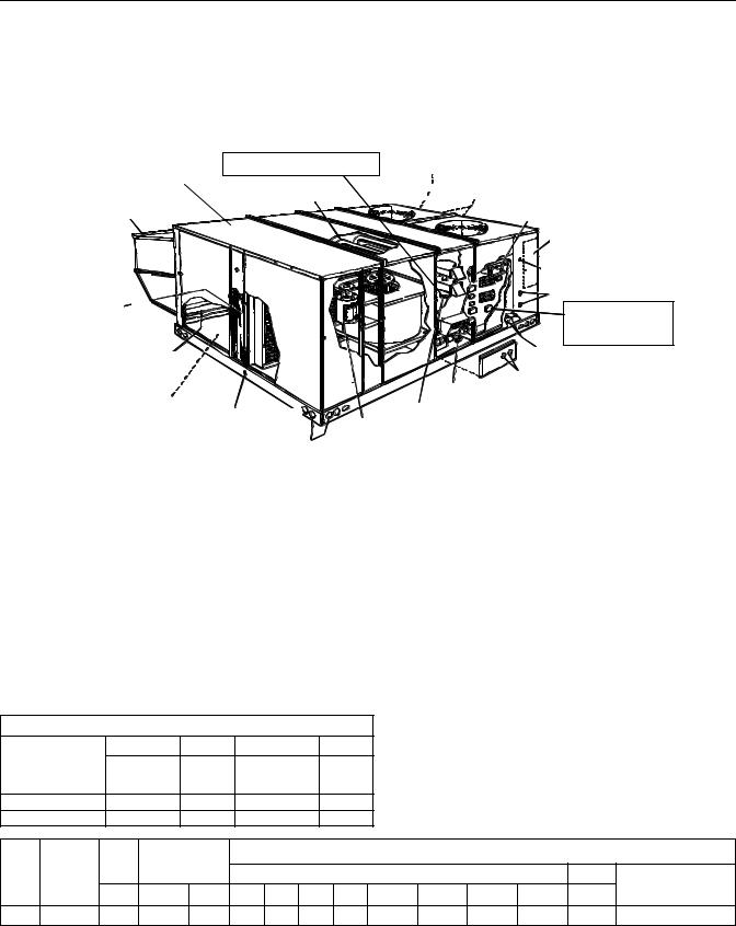
Sunline™ 2000 series convertible package rooftop models have two independent refrigerant circuits for efficient part load operation. Although the units are primarily designed for curb mounting on a roof, they can also be slab-mounted at ground level or set on steel beams above a finished roof.
Cooling only, cooling with gas heat and cooling with electric heat models are available with a wide variety of factorymounted options and field-installed accessories to make them suitable for almost every application.
All units are self-contained and assembled on full perimeter base rails with holes in the four corners for overhead rigging.
Every unit is completely piped, wired, charged and tested at the factory to simplify field installation and to provide years of dependable operation. Powder paint cabinets provide an exceptionally durable finish with the 750 hour salt spray process per ASTM-B117 test standard.
All models (including those with an economizer) are suitable for either bottom or horizontal duct connections. Models with power exhaust are suitable for bottom duct connections only. For bottom duct, you remove the sheet metal panels from the supply and return air openings through the base of the unit. For horizontal duct, you replace the supply and return air panels on the rear of the unit with a side duct flange accessory.
All models are available with five different outdoor air damper options:
•Single enthalpy economizer
•Differential (dual) enthalpy economizer
•Single enthalpy economizer with power exhaust
•Differential (dual) enthalpy economizer with power exhaust
•Motorized outdoor air damper
A fixed outdoor air intake assembly is shipped in the return air compartment of all units ordered without an economizer or motorized outdoor air damper option. The assembly includes a rain hood with a damper that can be set for 10, 15 or 25% outdoor air. With bottom duct connections, the intake damper assembly should be mounted over the opening in the return air panel. With horizontal ductwork, it should be mounted on the return air duct.
FOR DISTRIBUTION USE ONLY - NOT TO BE USED AT POINT OF RETAIL SALE

036-21359-001-B-0302
All supply air blowers are equipped with a belt drive that can be adjusted to meet the exact requirements of the job. A high speed drive accessory is available for applications with a higher CFM and/or static pressure requirement.
All compressors include internal pressure relief. Every refrigerant circuit includes an expansion valve, a liquid line filter-drier, a discharge line high pressure switch and a suction line with a freezestat and low pressure/ loss of charge switch. The unit control circuit includes two 75 VA transformers, two 24-volt circuit breakers and a relay board with two compressor lockout circuits, a terminal strip for thermostat wiring, plus an additional set of pin connectors to simplify the interface of additional field controls.
All 208/230 and 460-volt models are ETL approved. All 208/230 and 575-volt models are CGA approved.
All models include a 1-year limited warranty on the complete unit. Compressors and electric heater elements carry an additional 4-year warranty. Aluminized steel tubular heat exchangers carry an additional 9- year warranty.
All gas heat models are built with two heating sections for two equal stages of capacity control. Each section includes a durable heat exchanger with aluminized steel tubes, a redundant gas valve, spark ignition, power venting, an ignition module for 100% shut-off and all of the safety controls required to meet the latest ANSI standards.
The gas supply piping can be routed into the heating compartment through a hole in the base pan of the unit or through a knockout in the piping panel on the front of the unit.
All electric heat models are wired for a single power source and include a bank of nickel chromium elements mounted at the discharge of the supply air blower to provide a high velocity and uniform distribution of air across the heating elements. Every element is fully protected against excessive current and temperature by fuses and two thermal limit switches.
The power supply wiring can be routed into the control box through a threaded pipe connection in the base pan of the unit or through a knockout in the wiring panel on the front of the unit.
All internal factory wiring is color coded and numbered for ease in servicing and troubleshooting.
FACTORY-INSTALLED OPTIONS
ECONOMIZERS
Interlocked outdoor and return air dampers are positioned by a fully modulating, spring return damper actuator capable of introducing up to 100% outdoor air with nominal 1% leakage type dampers. As the outdoor air intake dampers open, the return air dampers close. The changeover from compressor to economizer cooling is determined by one or two solid state enthalpy controls.
On single enthalpy, an outdoor air sensor determines when the outdoor air is cool and dry enough to provide “free” cooling. On differential enthalpy, one sensor monitors the outdoor air while a second sensor monitors the return air. Whenever the outdoor air is cooler and drier than the return air, the unit will switch to economizer operation. For either option, the first compressor stage can provide additional cooling during economizer operation if the room thermostat calls for second stage.
The dampers and controls are installed and wired at the factory. Only the accessory rain hood needs to be assembled and installed in the field.
These economizer options can be used on all duct configurations.
POWER EXHAUST
Both the single and differential economizer options are available with power exhaust. Whenever the outdoor air intake dampers are opened for free cooling, the exhaust fan will be energized to prevent the conditioned space from being over-pressurized during economizer operation.
The exhaust fan, motor and controls are installed and wired at the factory. Only the back-draft damper assembly needs to be field installed and the accessory rain hoods need to be assembled and installed in the field.
The power exhaust option can only be used on bottom duct configurations.
MOTORIZED OUTDOOR AIR INTAKE DAMPER
Interlocked outdoor and return air dampers are controlled by a 2-position, spring return damper actuator. The outdoor damper will open to some pre-set position whenever the supply air blower is operating and will drive fully closed when the blower shuts down.
The damper and controls are installed and wired at the factory. Only the accessory rain hood needs to be assembled in the field.
This damper option can be used on all duct configurations.
2 |
Unitary Products Group |
036-21359-001-B-0302
FIELD-INSTALLED ACCESSORIES
SINGLE INPUT ELECTRONIC ENTHALPY ECONOMIZERS
Includes a slide-in/plug-in damper assembly with fully modulating spring-return monitor actuator capable of introducing up to 100% outdoor air with nominal 1% leakage type dampers.
The enthalpy system contains one sensor that monitors the outdoor air and determines when the air is cool enough and dry enough to provide “free” cooling.
The rainhood is painted to match the basic unit and must be field-assembled before installing.
Power exhaust is not available as a field installed option.
DUAL INPUT ELECTRONIC ENTHALPY
ECONOMIZERS
Includes a slide-in / plug-in damper assembly with fully modulating spring-return monitor actuator capable of introducing up to 100% outdoor air with nominal 1% leakage type dampers.
This enthalpy system contains one sensor that monitors the outdoor air and one sensor that monitors the return air. The logic module compares these two values and modulates the dampers providing the maximum efficiency of economizer system.
The rainhood is painted to match the basic unit and must be field-assembled before installing.
Power exhaust is not available as a field installed option.
MOTORIZED OUTDOOR AIR INTAKE DAMPER
Includes a slide-in/plug-in damper assembly with a 2-position, spring return motor actuator which opens to some pre-set position whenever the supply air blower is operating and will drive fully closed when the blower unit shuts down.
The rain hood is painted to match the basic unit and must be field assembled before installing.
Power exhaust is not available as a field installed option.
ROOF CURBS
Fourteen inch high roof curbs provide a water-tight seal between the unit and the finished roof. These full perimeter curbs meet the requirements of the National Roofing Contractors Association (NRCA) and are shipped knocked-down for field assembly. They're designed to fit inside the base rails of the unit and include both a wood nailing strip and duct hanger supports.
ANTI-RECYCLE TIMERS
Two solid state timers prevent the compressors from short-cycling. Once a compressor is de-energized, it will remain de-energized for approximately five minutes.
HIGH ALTITUDE NATURAL GAS
Burner orifices and pilot orifices are provided for proper furnace operation at altitudes up to 6,000 feet.
PROPANE
Burner orifices, pilot orifices and gas valve parts are provided to convert a natural gas furnace to propane.
HIGH ALTITUDE PROPANE
Burner orifices and pilot orifices are provided for proper furnace operation at altitudes up to 6,000 feet. This accessory supplements the basic propane conversion kit.
SIDE DUCT FLANGES
One inch flanges replace the supply and return air panels on the rear of the unit to accommodate horizontal duct connections. These flanges can also be used individually for bottom supply/horizontal return or horizontal supply/bottom return. They cannot be used on units with power exhaust.
BAROMETRIC RELIEF DAMPER
This damper accessory can be used to relieve internal air pressure on units with an economizer but no power exhaust. This accessory includes a rain hood, a bird screen and a fully assembled damper. With bottom duct connections, the damper should be mounted over the opening in the return air panel. With horizontal ductwork, the accessory should be mounted on the return air duct.
ECONOMIZER / POWER EXHAUST RAIN HOODS
A rain hood accessory must be used on units with an economizer, a motorized damper, or a combined economizer with power exhaust option. These accessories include all the hood panels, the necessary components and hardware for field assembly.
HIGH SPEED DRIVE
A smaller blower pulley and a shorter belt increase the speed of the supply air blower for applications with a higher CFM and/or static pressure requirement.
LOW AMBIENT CONTROLS TO 0°F
An autotransformer and a thermostat maintain stable system operation by reducing the speed of the condenser fan motor at low outdoor temperatures. The kit
Unitary Products Group |
3 |
036-21359-001-B-0302
also includes a 1-phase motor to replace the unit's Provides coil guard and fastners. standard 3-phase condenser fan motor. Standard units
can operate down to 45°F.
COIL GUARD KIT
E L E C T R I C H E A T E  R
R 

 L
L
 O
O C
C A
A  T
T I O
I O
 N
N
L O N G L A S T(IONPGT I O N A L E L E CHT IRG
IRG IHC
IHC /EEFLFEICCTIRE INCC YU NSICT RS O) L L C O M P R E S S O R S
P O W D E R P A I N T F I N I S H
2 0
0


 G
G
 A
A
 U
U
 G
G  E T
E T
 U
U B
B  U
U
 L A
L A R
R


E  C
C O
O

 N
N  O
O
 M I Z E R H O O D

 A L U M I N I Z E
  D CSOTPEPEELR T U B E / A L U M I N U M F I N
 H E A T E X C H
  A NCGOENRDSE N S E R C O I L S
L
 O
O  W
W


 V
V O
O
 L
L
 T
T A G E R E L A Y B O A R D A
 N
N  D
D


 T
T
 E
E
 R M I A N L S T R I P
E L
L E
E
 C
C T
T  R
R I
I C A L D I S C O N N E C T M
 O
O U N T
U N T I N G L O C A T I O N
( F ie ld in s t a lle d )
|
K N O C K O U T F O R |
|
|
S I D E C O N T R O L W I R I N G E N T R Y |
|
|
K N O C K O U T F O R |
|
|
S I D E P O W E R W I R I N G E N T R Y |
|
2 " D I S P O S A B L E |
T E R M I N A L B L O C K |
|
F I L T E R S |
||
( F o r S in g le P o in t P o w e r S u p p |
||
|
||
|
w it h E le c t r ic H e a t ) |
|
OU T D O O R A I R O P E N I N G |
E L E C T R I C / E L E C T R I C U N I T S |
|
|
||
F O R S L I D E - I N / P L U G - I N |
B O T T O M P O W E R & C O N T R O L |
|
I N T E R N A L E C O N O M I Z E R ( O P T I O N ) |
||
W I R I N G E N T R Y |
||
|
||
S I D E A N D B O T T O M |
K N O C K O U T S F O R S I D E |
|
G A S S U P P L Y E N T R Y |
||
S U P P L Y & R E T U R N A I R |
H O L E F O R B O T T O M |
|
G A S S U P P L Y E N T R Y |
||
D U C T O P E N I N G S ( S I D E X S I D E ) |
||
|
||
1 "N PINTP T I |
P O W E R V E N T O R M O T O R |
|
W I T H P O S T P U R G E C Y C L E |
||
C O N D E N S A T E B DE RL AT |
||
I-ND R I V E |
||
B L O W E R M O T O R |
||
F U L L P E R I M E T E R 1 4 G U A G E B A S E
R A I L S W I T H L I F T I N G H O L E S
CAPACITY RATINGS - (ARI 360)* |
|
|
|
|
|
||
MODEL |
MBH |
EER |
IPLV |
MODEL |
MBH |
EER |
IPLV |
|
|
|
|
|
|
|
|
COOLING WITH GAS HEAT |
|
|
COOLING WITH ELECTRIC HEAT |
|
|
|
|
|
|
|
|
|
|
|
|
D2CG300N240 |
290 |
8.5 |
8.3 |
D2CE300E018 |
290 |
8.5 |
8.6 |
|
|
|
|
|
|
|
|
D2CG300N320 |
290 |
8.5 |
8.3 |
D2CE300E036 |
290 |
8.5 |
8.6 |
|
|
|
|
|
|
|
|
COOLING ONLY |
|
|
|
D2CE300E054 |
287 |
8.5 |
8.2 |
|
|
|
|
|
|
|
|
D2CE300 |
290 |
8.5 |
8.7 |
D2CE300E072 |
284 |
8.5 |
8.2 |
|
|
|
|
|
|
|
|
*. Outside the scope of ARI Standard 340/360.
EER=Energy Efficiency Rating at full load-the cooling capacity in Btu’s per hour (Btuh) divided by the power input in watts, expressed in Btuh per watt (Btuh/watt).
IPLV - Integrated part load value. NOTE: All cooling is three stage.
|
|
GAS HEAT RATINGS |
|
|
|
Note: All gas units are two-stage heating. First stage is 50% of total. |
|||||||||
|
|
|
|
|
All models are 80% Steady State Efficiency (S.S.E.). |
|
|||||||||
|
|
MBH Input |
|
MBH Output |
|
|
|||||||||
|
|
|
|
|
|
|
|
|
|
||||||
MODEL |
Stage |
Stage 1 |
Stage |
Stage 1 |
|
|
|
|
|
|
|||||
|
|
1&2 |
|
1&2 |
|
|
|
|
|
|
|||||
|
|
|
|
|
|
|
|
|
|
|
|
||||
D2CG300N240 |
|
300 |
150 |
|
240 |
|
120 |
|
|
|
|
|
|
||
D2CG300N320 |
|
400 |
200 |
|
320 |
|
160 |
|
|
|
|
|
|
||
Unit |
CFM |
ESP |
Blower |
|
|
|
|
Sound Power (db 10-12 Watts) |
|
||||||
|
Octave Band Centerline Frequency (Hz) |
SWL |
db(A) |
||||||||||||
Size |
) |
|
|
|
|
||||||||||
IWG |
RPM |
BHP |
63 |
125 |
250 |
500 |
1,000 |
2,000 |
4,000 |
8,000 |
db(A) |
@ 10 Ft.* |
|||
|
|
||||||||||||||
300 |
10,000 |
1.30 |
1,160 |
12.5 |
108 |
108 |
98 |
91 |
93 |
86 |
81 |
76 |
98 |
65 |
|
*. At a distance of 10 ft.from the blower.
NOTE: These values have been derived using a model of sound propagation, measuring the indoor ambient sound levels ten feet from the source. The dBA values provided are for reference only. Calculation of dBA values cover matters of system design and application. This constitutes an exception to any specifi-
cation or guarantee requiring a dBA value or sound data in any other form than sound power level ratings.
4 |
Unitary Products Group |

036-21359-001-B-0302
COOLING CAPACITIES- 25 TON (DCE / DCG300)
Air On |
|
|
|
|
|
Tem pera ture of Air on Con denser Coil |
|
|
|
|
|
|
||||||||
|
|
|
85? F |
|
|
|
|
|
|
|
95? F |
|
|
|
|
|||||
Evaporator |
|
|
|
|
|
|
|
|
|
|
|
|
|
|
||||||
Coil |
|
Total |
Power |
|
SensibleCapacity1, MBH |
|
Total |
Power |
|
SensibleCapacity1, MBH |
|
|||||||||
CFM |
WB |
Cap.1 |
Input2 |
|
En ter ing Dry Bulb, ? F |
|
Cap.1 |
Input2 |
|
En ter ing Dry Bulb, ? F |
|
|||||||||
? F |
MBH |
KW |
86 |
83 |
80 |
77 |
74 |
71 |
68 |
MBH |
KW |
86 |
83 |
80 |
77 |
74 |
71 |
68 |
||
|
||||||||||||||||||||
|
72 |
371 |
27.1 |
277 |
240 |
203 |
167 |
130 |
- |
- |
354 |
28.8 |
268 |
231 |
195 |
158 |
122 |
- |
- |
|
12,000 |
67 |
340 |
26.1 |
335 |
299 |
262 |
226 |
189 |
152 |
116 |
325 |
27.7 |
324 |
288 |
251 |
214 |
178 |
141 |
105 |
|
62 |
329 |
25.5 |
329 |
329 |
329 |
293 |
256 |
219 |
183 |
315 |
27.1 |
315 |
315 |
315 |
278 |
241 |
205 |
168 |
||
|
||||||||||||||||||||
|
57 |
329 |
25.5 |
329 |
329 |
329 |
292 |
256 |
219 |
183 |
314 |
27.1 |
314 |
314 |
314 |
278 |
241 |
205 |
168 |
|
|
72 |
365 |
27.0 |
260 |
226 |
193 |
159 |
125 |
- |
- |
348 |
28.6 |
257 |
223 |
189 |
155 |
122 |
- |
- |
|
11,000 |
67 |
336 |
25.9 |
317 |
283 |
249 |
216 |
182 |
148 |
114 |
321 |
27.5 |
312 |
279 |
245 |
211 |
178 |
144 |
110 |
|
62 |
324 |
25.3 |
324 |
324 |
313 |
279 |
245 |
212 |
178 |
309 |
26.9 |
309 |
309 |
307 |
273 |
239 |
206 |
172 |
||
|
||||||||||||||||||||
|
57 |
324 |
25.3 |
324 |
324 |
315 |
281 |
247 |
214 |
180 |
309 |
26.9 |
309 |
309 |
309 |
275 |
242 |
208 |
174 |
|
|
72 |
359 |
26.8 |
244 |
213 |
182 |
151 |
120 |
- |
- |
342 |
28.5 |
245 |
214 |
184 |
153 |
122 |
- |
- |
|
10,000 |
67 |
332 |
25.7 |
298 |
268 |
237 |
206 |
175 |
144 |
113 |
317 |
27.4 |
301 |
270 |
239 |
208 |
177 |
146 |
115 |
|
62 |
318 |
25.2 |
318 |
318 |
296 |
265 |
235 |
204 |
173 |
304 |
26.8 |
304 |
304 |
299 |
268 |
237 |
207 |
176 |
||
|
||||||||||||||||||||
|
57 |
318 |
25.1 |
318 |
318 |
301 |
270 |
239 |
208 |
177 |
304 |
26.7 |
304 |
304 |
304 |
273 |
242 |
211 |
180 |
|
|
72 |
354 |
26.6 |
229 |
201 |
173 |
145 |
117 |
- |
- |
338 |
28.2 |
228 |
200 |
172 |
144 |
116 |
- |
- |
|
9,000 |
67 |
326 |
25.5 |
280 |
252 |
224 |
196 |
168 |
141 |
113 |
312 |
27.1 |
279 |
251 |
223 |
195 |
167 |
139 |
111 |
|
62 |
314 |
25.0 |
314 |
306 |
282 |
254 |
226 |
198 |
170 |
300 |
26.5 |
300 |
295 |
280 |
253 |
225 |
197 |
169 |
||
|
||||||||||||||||||||
|
57 |
314 |
25.0 |
314 |
308 |
286 |
258 |
230 |
203 |
175 |
300 |
26.5 |
300 |
297 |
285 |
257 |
229 |
201 |
173 |
|
|
72 |
349 |
26.4 |
215 |
190 |
165 |
140 |
115 |
- |
- |
334 |
28.0 |
211 |
186 |
161 |
136 |
111 |
- |
- |
|
8,000 |
67 |
321 |
25.3 |
262 |
237 |
212 |
187 |
162 |
137 |
112 |
307 |
26.9 |
257 |
232 |
207 |
182 |
157 |
132 |
107 |
|
62 |
310 |
24.8 |
310 |
293 |
268 |
243 |
218 |
193 |
168 |
297 |
26.3 |
297 |
287 |
262 |
237 |
212 |
187 |
162 |
||
|
||||||||||||||||||||
|
57 |
310 |
24.8 |
310 |
297 |
272 |
247 |
222 |
197 |
172 |
297 |
26.3 |
297 |
291 |
266 |
241 |
216 |
191 |
166 |
|
|
72 |
318 |
25.2 |
186 |
167 |
148 |
129 |
110 |
- |
- |
304 |
26.8 |
177 |
158 |
138 |
119 |
100 |
- |
- |
|
6,000 |
67 |
290 |
24.0 |
226 |
206 |
187 |
168 |
149 |
130 |
111 |
277 |
25.5 |
213 |
194 |
175 |
156 |
137 |
118 |
99 |
|
62 |
282 |
23.7 |
277 |
258 |
240 |
221 |
201 |
192 |
163 |
270 |
25.2 |
262 |
243 |
225 |
206 |
187 |
167 |
148 |
||
|
||||||||||||||||||||
|
57 |
282 |
23.7 |
281 |
262 |
243 |
224 |
205 |
186 |
167 |
270 |
25.2 |
266 |
247 |
228 |
209 |
190 |
171 |
152 |
|
Air On |
|
|
|
|
|
Tem pera ture of Air on Con denser Coil |
|
|
|
|
|
|
||||||||
|
|
|
105? F |
|
|
|
|
|
|
|
115? F |
|
|
|
|
|||||
Evaporator |
|
|
|
|
|
|
|
|
|
|
|
|
|
|
||||||
Coil |
|
Total |
Power |
|
SensibleCapacity1, MBH |
|
Total |
Power |
|
SensibleCapacity1, MBH |
|
|||||||||
CFM |
WB |
Cap.1 |
Input2 |
|
En ter ing Dry Bulb, ? F |
|
Cap.1 |
Input2 |
|
En ter ing Dry Bulb, ? F |
|
|||||||||
? F |
MBH |
KW |
86 |
83 |
80 |
77 |
74 |
71 |
68 |
MBH |
KW |
86 |
83 |
80 |
77 |
74 |
71 |
68 |
||
|
||||||||||||||||||||
|
72 |
337 |
30.7 |
264 |
228 |
191 |
155 |
118 |
- |
- |
320 |
32.6 |
261 |
224 |
188 |
151 |
114 |
- |
- |
|
12,000 |
67 |
310 |
29.5 |
309 |
283 |
246 |
210 |
173 |
137 |
100 |
294 |
31.3 |
294 |
278 |
242 |
205 |
169 |
132 |
95 |
|
|
62 |
300 |
28.8 |
300 |
300 |
300 |
263 |
226 |
190 |
153 |
285 |
30.5 |
285 |
285 |
285 |
248 |
212 |
175 |
138 |
|
|
57 |
299 |
28.8 |
299 |
299 |
299 |
263 |
226 |
190 |
153 |
285 |
30.5 |
285 |
285 |
285 |
248 |
211 |
175 |
138 |
|
|
72 |
331 |
30.5 |
254 |
221 |
187 |
153 |
119 |
- |
- |
315 |
32.3 |
252 |
218 |
185 |
151 |
117 |
- |
- |
|
11,000 |
67 |
306 |
29.3 |
302 |
276 |
242 |
208 |
174 |
141 |
107 |
291 |
31.0 |
291 |
273 |
239 |
205 |
171 |
138 |
104 |
|
62 |
295 |
28.5 |
295 |
295 |
294 |
260 |
226 |
192 |
159 |
280 |
30.3 |
280 |
280 |
280 |
246 |
213 |
179 |
145 |
||
|
||||||||||||||||||||
|
57 |
294 |
28.5 |
294 |
294 |
294 |
261 |
227 |
193 |
160 |
280 |
30.3 |
280 |
280 |
280 |
246 |
213 |
179 |
145 |
|
|
72 |
326 |
30.2 |
244 |
213 |
183 |
152 |
121 |
- |
- |
310 |
32.1 |
243 |
212 |
181 |
151 |
120 |
- |
- |
|
10,000 |
67 |
302 |
29.0 |
294 |
268 |
237 |
206 |
176 |
145 |
114 |
287 |
30.8 |
287 |
267 |
236 |
205 |
174 |
143 |
112 |
|
62 |
290 |
28.3 |
290 |
290 |
287 |
256 |
226 |
195 |
164 |
276 |
30.0 |
276 |
276 |
276 |
245 |
214 |
183 |
152 |
||
|
57 |
290 |
28.2 |
290 |
290 |
290 |
259 |
228 |
197 |
166 |
275 |
29.9 |
275 |
275 |
275 |
244 |
214 |
183 |
152 |
|
|
72 |
322 |
30.0 |
228 |
200 |
172 |
144 |
116 |
- |
- |
306 |
31.8 |
228 |
200 |
172 |
144 |
116 |
- |
- |
|
9,000 |
67 |
297 |
28.8 |
276 |
251 |
223 |
195 |
167 |
139 |
111 |
283 |
30.5 |
274 |
251 |
223 |
195 |
167 |
139 |
111 |
|
62 |
286 |
28.1 |
286 |
284 |
271 |
243 |
215 |
187 |
159 |
272 |
29.8 |
272 |
272 |
262 |
234 |
206 |
178 |
150 |
||
|
||||||||||||||||||||
|
57 |
286 |
28.1 |
286 |
285 |
273 |
245 |
217 |
189 |
161 |
272 |
29.7 |
272 |
272 |
261 |
234 |
206 |
178 |
150 |
|
|
72 |
319 |
29.8 |
212 |
187 |
162 |
137 |
112 |
- |
- |
303 |
31.6 |
213 |
188 |
163 |
138 |
113 |
- |
- |
|
8,000 |
67 |
293 |
28.6 |
259 |
234 |
209 |
184 |
159 |
134 |
109 |
278 |
30.3 |
260 |
235 |
210 |
185 |
160 |
135 |
110 |
|
62 |
283 |
28.0 |
283 |
278 |
255 |
230 |
205 |
180 |
155 |
269 |
29.6 |
269 |
269 |
248 |
223 |
198 |
173 |
148 |
||
|
||||||||||||||||||||
|
57 |
283 |
28.0 |
283 |
280 |
257 |
232 |
207 |
182 |
157 |
269 |
29.6 |
269 |
269 |
248 |
223 |
198 |
173 |
148 |
|
|
72 |
290 |
28.3 |
180 |
161 |
141 |
122 |
103 |
- |
- |
276 |
30.0 |
183 |
164 |
145 |
125 |
106 |
- |
- |
|
6,000 |
67 |
264 |
26.9 |
224 |
200 |
181 |
162 |
142 |
123 |
104 |
251 |
28.5 |
222 |
203 |
194 |
165 |
146 |
127 |
108 |
|
62 |
258 |
26.6 |
258 |
241 |
223 |
204 |
184 |
165 |
146 |
245 |
28.2 |
245 |
239 |
220 |
201 |
182 |
163 |
144 |
||
|
||||||||||||||||||||
|
57 |
258 |
26.6 |
258 |
242 |
224 |
205 |
186 |
167 |
148 |
245 |
28.2 |
245 |
240 |
221 |
202 |
182 |
163 |
144 |
|
1These ca paci ties are gross rat ings. For net ca pac ity, de duct the heat of the sup ply air blower mo tor, MBH = 3.415 x KW. Ref er to the ap pro pri ate Blower Per form ance Ta ble for the KW of the sup ply air blower mo tor.
2These rat ings in clude the con denser fan mo tors (To tal 2.3 KW) and the com pres sor mo tors but not the sup ply air blower mo tor.
|
NominalRating |
|
AllSensibleCapacity |
Unitary Products Group |
5 |

036-21359-001-B-0302
BLOWER PERFORMANCE- 25 TON (DCE/DCG300)
DCE300- BOT TOM DUCT CON NEC TIONS (COOLINGAPPLICATIONS)
BLOWER |
PULLEY |
|
7500 CFM |
|
|
8750 CFM |
|
|
10000 CFM |
|
|
11250 CFM |
|
|
12500 CFM |
|
|||
SPEED |
TURNS |
ESP |
OUTPUT |
INPUT |
ESP |
OUTPUT |
INPUT |
ESP |
OUTPUT |
|
INPUT |
ESP |
OUTPUT |
|
INPUT |
ESP |
OUTPUT |
|
INPUT |
(rpm) |
OPEN: |
(iwg) |
(bhp) |
(kW) |
(iwg) |
(bhp) |
(kW) |
(iwg) |
(bhp) |
|
(kW) |
(iwg) |
(bhp) |
|
(kW) |
(iwg) |
(bhp) |
|
(kW) |
|
|
|
|
|
|
|
STANDARD DRIVE: |
|
|
|
|
|
|
|
|
|
|||
975 |
6.0* |
1.4 |
5.9 |
4.9 |
1.0 |
7.3 |
6.0 |
0.5 |
8.8 |
|
7.2 |
- |
- |
|
- |
- |
- |
|
- |
1005 |
5.0 |
1.6 |
6.2 |
5.1 |
1.2 |
7.7 |
6.3 |
0.7 |
9.2 |
|
7.6 |
0.1 |
10.9 |
|
8.9 |
- |
- |
|
- |
1040 |
4.0 |
1.8 |
6.6 |
5.4 |
1.4 |
8.1 |
6.7 |
0.9 |
9.7 |
|
8.0 |
0.3 |
11.4 |
|
9.4 |
- |
- |
|
- |
1070 |
3.0 |
2.0 |
6.9 |
5.7 |
1.6 |
8.5 |
7.0 |
1.1 |
10.2 |
|
8.3 |
0.6 |
11.9 |
|
9.8 |
- |
- |
|
- |
1100 |
2.0 |
2.1 |
7.3 |
6.0 |
1.8 |
8.9 |
7.3 |
1.3 |
10.6 |
|
8.7 |
0.8 |
12.4 |
|
10.2 |
0.2 |
14.3 |
|
11.7 |
1135 |
1.0 |
2.4 |
7.7 |
6.3 |
2.0 |
9.3 |
7.6 |
1.6 |
11.1 |
|
9.1 |
1.0 |
13.0 |
|
10.6 |
0.4 |
14.9 |
|
12.2 |
1165 |
0.0 |
2.6 |
8.0 |
6.6 |
2.2 |
9.7 |
8.0 |
1.8 |
11.6 |
|
9.5 |
1.3 |
13.5 |
|
11.0 |
0.7 |
15.5 |
|
12.7 |
|
|
|
|
|
|
|
ACCESSORY DRIVE: |
|
|
|
|
|
|
|
|
|
|||
1140 |
6.0 |
2.4 |
7.7 |
6.3 |
2.1 |
9.4 |
7.7 |
1.6 |
11.2 |
|
9.2 |
1.1 |
13.1 |
|
10.7 |
0.5 |
15.0 |
|
12.3 |
1180 |
5.0 |
2.7 |
8.2 |
6.7 |
2.3 |
9.9 |
8.1 |
1.9 |
11.8 |
|
9.7 |
1.4 |
13.7 |
|
11.2 |
0.8 |
15.8 |
|
12.9 |
1215 |
4.0 |
2.9 |
8.6 |
7.0 |
2.6 |
10.4 |
8.5 |
2.2 |
12.3 |
|
10.1 |
1.7 |
14.3 |
|
11.7 |
1.1 |
16.4 |
|
13.5 |
1255 |
3.0 |
3.2 |
9.1 |
7.4 |
2.9 |
11.0 |
9.0 |
2.5 |
12.9 |
|
10.6 |
2.0 |
15.0 |
|
12.3 |
1.4 |
17.2 |
|
14.1 |
1290 |
2.0 |
3.4 |
9.5 |
7.8 |
3.1 |
11.5 |
9.4 |
2.7 |
13.5 |
|
11.1 |
2.2 |
15.6 |
|
12.8 |
- |
- |
|
- |
1330 |
1.0 |
3.7 |
10.0 |
8.2 |
3.4 |
12.0 |
9.9 |
3.0 |
14.1 |
|
11.6 |
2.6 |
16.4 |
|
13.4 |
- |
- |
|
- |
1365 |
0.0 |
3.9 |
10.5 |
8.6 |
3.7 |
12.6 |
10.3 |
3.3 |
14.7 |
|
12.1 |
2.9 |
17.0 |
|
13.9 |
- |
- |
|
- |
NOTES:
Blower performance is based on cooling only unit, with fixed outdoor air, 2" T/A filters and a dry evaporator coil. Refer to page 7 for additional static resistances.
ESP - External Static Pressure available for the supply and return air duct system. All internal unit resistances have been deducted from the total static pressure of the blower.
* FACTORY SETTING
BLOWER PERFORMANCE - 25 TON (DCE/DCG300)
DCG300 - BOT TOM DUCT CON NEC TIONS (COOLINGAPPLICATIONS)
BLOWER |
PULLEY |
|
7500 CFM |
|
|
8750 CFM |
|
|
10000 CFM |
|
|
11250 CFM |
|
|
12500 CFM |
|
|||
SPEED |
TURNS |
ESP |
OUTPUT |
INPUT |
ESP |
OUTPUT |
INPUT |
ESP |
OUTPUT |
|
INPUT |
ESP |
OUTPUT |
|
INPUT |
ESP |
OUTPUT |
|
INPUT |
(rpm) |
OPEN: |
(iwg) |
(bhp) |
(kW) |
(iwg) |
(bhp) |
(kW) |
(iwg) |
(bhp) |
|
(kW) |
(iwg) |
(bhp) |
|
(kW) |
(iwg) |
(bhp) |
|
(kW) |
|
|
|
|
|
|
|
STANDARD DRIVE: |
|
|
|
|
|
|
|
|
|
|||
975 |
6.0* |
1.2 |
5.9 |
4.9 |
0.5 |
7.3 |
6.0 |
- |
- |
|
- |
- |
- |
|
- |
- |
- |
|
- |
1005 |
5.0 |
1.4 |
6.2 |
5.1 |
0.7 |
7.7 |
6.3 |
- |
- |
|
- |
- |
- |
|
- |
- |
- |
|
- |
1040 |
4.0 |
1.6 |
6.6 |
5.4 |
0.9 |
8.1 |
6.7 |
0.2 |
9.7 |
|
8.0 |
- |
- |
|
- |
- |
- |
|
- |
1070 |
3.0 |
1.8 |
6.9 |
5.7 |
1.1 |
8.5 |
7.0 |
0.4 |
10.2 |
|
8.3 |
- |
- |
|
- |
- |
- |
|
- |
1100 |
2.0 |
2.0 |
7.3 |
6.0 |
1.3 |
8.9 |
7.3 |
0.6 |
10.6 |
|
8.7 |
- |
- |
|
- |
- |
- |
|
- |
1135 |
1.0 |
2.2 |
7.7 |
6.3 |
1.6 |
9.3 |
7.6 |
0.8 |
11.1 |
|
9.1 |
- |
- |
|
- |
- |
- |
|
- |
1165 |
0.0 |
2.4 |
8.0 |
6.6 |
1.8 |
9.7 |
8.0 |
1.0 |
11.6 |
|
9.5 |
0.2 |
13.5 |
|
11.0 |
- |
- |
|
- |
|
|
|
|
|
|
|
ACCESSORY DRIVE: |
|
|
|
|
|
|
|
|
|
|||
1140 |
6.0 |
2.2 |
7.7 |
6.3 |
1.6 |
9.4 |
7.7 |
0.9 |
11.2 |
|
9.2 |
- |
- |
|
- |
- |
- |
|
- |
1180 |
5.0 |
2.5 |
8.2 |
6.7 |
1.9 |
9.9 |
8.1 |
1.2 |
11.8 |
|
9.7 |
0.3 |
13.7 |
|
11.2 |
- |
- |
|
- |
1215 |
4.0 |
2.7 |
8.6 |
7.0 |
2.1 |
10.4 |
8.5 |
1.4 |
12.3 |
|
10.1 |
0.6 |
14.3 |
|
11.7 |
- |
- |
|
- |
1255 |
3.0 |
3.0 |
9.1 |
7.4 |
2.4 |
11.0 |
9.0 |
1.7 |
12.9 |
|
10.6 |
0.9 |
15.0 |
|
12.3 |
- |
- |
|
- |
1290 |
2.0 |
3.2 |
9.5 |
7.8 |
2.7 |
11.5 |
9.4 |
2.0 |
13.5 |
|
11.1 |
1.2 |
15.6 |
|
12.8 |
- |
- |
|
- |
1330 |
1.0 |
3.5 |
10.0 |
8.2 |
3.0 |
12.0 |
9.9 |
2.3 |
14.1 |
|
11.6 |
1.5 |
16.4 |
|
13.4 |
- |
- |
|
- |
1365 |
0.0 |
3.7 |
10.5 |
8.6 |
3.2 |
12.6 |
10.3 |
2.6 |
14.7 |
|
12.1 |
1.8 |
17.0 |
|
13.9 |
- |
- |
|
- |
NOTES:
Blower performance is based on cooling only unit, with fixed outdoor air, 2" T/A filters and a dry evaporator coil. Refer to page 7 for additional static resistances.
ESP - External Static Pressure available for the supply and return air duct system. All internal unit resistances have been deducted from the total static pressure of the blower.
* FACTORY SETTING
6 |
Unitary Products Group |

036-21359-001-B-0302
ELECTRICAL DATA - Units With Elec tric Heat
|
|
ELECTRIC HEATER OPTION |
MINIMUM |
MAXIMUM |
||||
MODEL |
POWER |
CIRCUIT |
OVERCURRENT |
|||||
|
|
|
|
|||||
D2CE |
SUPPLY |
MODEL |
kW(1) |
STAGES |
AMPS |
AMPACITY |
DEVICE (1) |
|
|
|
|
|
|||||
|
|
|
|
|
|
(AMPS) |
(AMPS) |
|
300A25 |
208-3-60 |
E018 |
13.5 |
1 |
37.5 |
139.5 |
175 |
|
300A25 |
208-3-60 |
E036 |
27.0 |
2 |
75.1 |
142.1 |
175 |
|
300A25 |
208-3-60 |
E054 |
40.6 |
2 |
112.6 |
189.0 |
200 |
|
300A25 |
208-3-60 |
E072 |
54.1 |
2 |
150.1 |
198.4 |
225 |
|
300A25 |
230-3-60 |
E018 |
18.0 |
1 |
43.3 |
139.5 |
175 |
|
300A25 |
230-3-60 |
E036 |
36.0 |
2 |
86.6 |
156.5 |
175 |
|
300A25 |
230-3-60 |
E054 |
54.0 |
2 |
129.9 |
178.2 |
200 |
|
300A25 |
230-3-60 |
E072 |
72.0 |
2 |
173.2 |
221.5 |
250 |
|
300A46 |
460-3-60 |
E018 |
18.0 |
1 |
21.7 |
68.3 |
80 |
|
300A46 |
460-3-60 |
E036 |
36.0 |
2 |
43.3 |
78.3 |
80 |
|
300A46 |
460-3-60 |
E054 |
54.0 |
2 |
65.0 |
89.1 |
100 |
|
300A46 |
460-3-60 |
E072 |
72.0 |
2 |
86.6 |
110.7 |
125 |
|
300A58 |
575-3-60 |
E018 |
18.0 |
1 |
17.3 |
56.1 |
70 |
|
300A58 |
575-3-60 |
E036 |
36.0 |
2 |
34.6 |
62.6 |
70 |
|
300A58 |
575-3-60 |
E054 |
54.0 |
2 |
52.0 |
71.2 |
80 |
|
300A58 |
575-3-60 |
E072 |
72.0 |
2 |
69.3 |
88.5 |
100 |
|
1 |
|
|
|
|
NOMINALVOLTAGE |
VOLTAGE |
KWCAP.MULTIPLIER |
|
208 |
208 |
1.00 |
|
240 |
230 |
0.92 |
|
480 |
460 |
0.92 |
|
600 |
575 |
0.92 |
PHYSICAL DATA
BASIC UNITS
MODELS
DCE/DCG/DCV
300
EVAPORATOR
BLOWER
EVAPORATOR
COIL
CONDENSER
FAN
(Two Per Unit)
CONDENSER
COIL
COMPRESSOR
(Qty. Per Unit)
AIR
FILTERS
CHARGE
CEN TRIFU GAL BLOWER (Dia. x Wd. in.) |
18 x 15 |
|||
FAN MO TOR HP |
|
15 |
||
ROWS DEEP |
|
4 |
||
FINS PER INCH |
|
13.5 |
||
FACE AREA (Sq. Ft.) |
|
25.0 |
||
PRO PEL LER DIA. (in.) |
(Each) |
30 |
||
FAN MO TOR HP |
(Each) |
1 |
||
NOM. CFM TO TAL |
(Each) |
7200 |
||
ROWS DEEP |
|
3 |
||
FINS PER INCH |
|
15 |
||
FACE AREA (Sq. Ft.) |
|
43.3 |
||
12.5 TON, SCROLL, HER METIC, |
2 |
|||
TAN DEM (2 STAGE, 50% ea.) |
||||
|
||||
QUAN TITY PER UNIT (16" X 20" X 2") |
2 |
|||
QUAN TITY PER UNIT (16" X 25" X 2") |
4 |
|||
QUAN TITY PER UNIT (14" X 20" X 2") |
3 |
|||
TO TAL FACE AREA (sq. ft.) |
21.4 |
|||
REFRIGERANT |
SYS TEM NO. 1 |
20/8 |
||
22 (lbs./oz.) |
|
|
|
|
|
SYS TEM NO. 2 |
20/0 |
||
OPERATING WEIGHTS
|
MODEL SIZE (MBH) |
|
300 |
|
|
DCE (Cool ing only) |
|
2730 |
|
|
DCV (Cool ing only) |
|
2795 |
|
Ba sic Unit |
DCG (Gas / Elec tric) |
N240 |
2930 |
|
N320 |
2970 |
|||
|
|
|||
|
DCV (Gas / Elec tric) |
N240 |
2995 |
|
|
N320 |
3035 |
||
|
|
|||
|
Economizer |
|
160 |
|
|
Econo mizer with |
|
245 |
|
|
Power Ex haust |
|
||
|
|
|
||
Options MotorizedDamper |
|
150 |
||
|
|
18 KW |
25 |
|
|
Elec tric Heater |
36 KW |
30 |
|
|
(Elec/Elec only) |
54 KW |
35 |
|
|
|
72 KW |
40 |
|
|
Roof Curb |
|
185 |
|
|
BarometricDamper |
|
45 |
|
Accesso- |
Economizer/MotorizedDamper |
55 |
||
Rain Hood |
|
|||
ries |
Econo mizer/Power Ex haust Rain |
90 |
||
|
||||
|
Hood |
|
||
|
|
|
||
|
Wood Skid |
|
220 |
|
Unitary Products Group |
7 |

|
|
|
|
|
|
|
|
|
|
|
|
|
|
|
|
|
|
|
|
|
|
|
|
|
|
|
|
|
|
|
|
|
|
|
|
|
|
036-21359-001-B-0302 |
||||
|
BLOWER MOTOR AND DRIVE DATA |
|
|
|
|
|
|
|
|
|
|
|
|
|
|
|
|
|
|
|
|
|
||||||||||||||||||||
|
|
|
|
|
|
|
|
|
|
|
MOTOR1 |
|
|
ADJUSTABLEMOTORPULLEY |
|
FIXED BLOWER PUL LEY |
|
BELT |
|
|
||||||||||||||||||||||
|
|
|
|
|
|
|
|
|
|
|
|
|
|
|
|
|
||||||||||||||||||||||||||
|
|
|
|
|
|
|
BLOWER |
|
|
|
|
|
|
|
|
|
|
|
|
|
|
|
|
|
|
|
|
|
|
|
|
|
|
|
|
(NOTCHED) |
|
|
||||
|
|
MODEL |
|
DRIVE |
RANGE |
|
|
|
|
|
|
|
|
|
OUT- |
PITCH |
|
|
|
|
|
OUTSIDE |
PITCH |
|
|
|
PITCH |
|
|
|
||||||||||||
|
|
SIZE |
|
FRAME |
EFF. |
|
|
DESIG- |
|
SIDE |
BORE |
|
DESIG- |
BORE |
DESIG- |
|
QTY. |
|||||||||||||||||||||||||
|
|
|
|
|
|
|
(RPM) |
|
HP |
(%) |
|
|
NATION |
|
DIA. |
DIA. |
(IN.) |
|
NATION |
|
DIA. |
|
|
DIA. |
|
(IN.) |
NATION |
LENGTH |
|
|||||||||||||
|
|
|
|
|
|
|
|
|
|
|
|
|
|
|
(IN.) |
|
|
(IN.) |
|
|
(IN.) |
|
(IN.) |
|
|
|
||||||||||||||||
|
|
|
|
|
|
|
|
|
|
|
|
|
|
|
|
|
|
|
|
(IN.) |
|
|
|
|
|
|
|
|
|
|
|
|
|
|
|
|||||||
|
|
|
|
|
|
|
|
|
|
|
|
|
|
|
|
|
|
|
|
|
|
|
|
|
|
|
|
|
|
|
|
|
|
|
|
|
|
|
|
|
||
|
|
|
|
Stan- |
|
975/1165 |
|
|
|
|
|
|
|
|
|
|
|
|
|
|
|
|
|
|
1B5V110 |
11.3 |
|
11.1 |
|
1-7/16 |
5VX860 |
86.0 |
|
1 |
|
|||||||
|
|
|
|
dard |
|
|
|
|
|
|
|
|
|
|
|
|
|
|
|
|
|
|
|
|
|
|
|
|||||||||||||||
|
|
|
|
|
|
|
|
|
|
|
|
|
1LVP58B70 |
|
|
|
6.2- |
|
|
|
|
|
|
|
|
|
|
|
|
|
|
|
|
|
|
|||||||
|
|
25 TON |
|
High |
|
|
|
15 |
254T |
91 |
|
|
7.5 |
1 5/8 |
|
|
|
|
|
|
|
|
|
|
|
|
|
|
|
|
||||||||||||
|
|
|
|
|
|
|
|
|
A |
|
7.4 |
|
|
|
|
|
|
|
|
|
|
|
|
|
|
|
|
|
||||||||||||||
|
|
|
|
Speed |
1140/1365 |
|
|
|
|
|
|
|
|
|
|
|
|
|
|
1B5V94 |
9.7 |
|
9.5 |
|
1-7/16 |
5VX840 |
84.0 |
|
1 |
|
||||||||||||
|
|
|
|
|
|
|
|
|
|
|
|
|
|
|
|
|
|
|
|
|
|
|
|
|
|
|||||||||||||||||
|
|
|
|
Access |
|
|
|
|
|
|
|
|
|
|
|
|
|
|
|
|
|
|
|
|
|
|
|
|
|
|
|
|
|
|
|
|
|
|
|
|
||
|
1All mo tors have a nomi nal speed of 1800 RPM, a 1.15 serv ice fac tor and a solid base. They can op er ate to the limit of their serv ice fac tor be cause they are lo cated in the mov ing air, upstream |
|||||||||||||||||||||||||||||||||||||||||
|
|
of any heat ing de vice. |
|
|
|
|
|
|
|
|
|
|
|
|
|
|
|
|
|
|
|
|
|
|
|
|
|
|
|
|
|
|
|
|
|
|
|
|
||||
|
STATIC RESISTANCES* |
|
|
|
|
|
|
|
|
|
|
|
|
|
|
|
|
|
|
|
|
|
|
|
|
|
|
|
|
|
||||||||||||
|
|
|
|
|
|
|
|
|
|
|
|
|
|
|
|
|
|
|
|
|
|
|
|
|
|
|
|
|
|
|
|
|
|
|
|
|
|
|
|
|
|
|
|
|
|
|
|
|
|
|
|
|
|
|
|
|
|
|
|
|
AIRFLOW (CFM) |
|
|
|
|
|
|
|
|
|
|
|
|
|
|
|
|
|
|
||||||
|
|
|
|
|
DESCRIPTION |
|
7500 |
|
8750 |
|
10000 |
|
11250 |
|
12500 |
|
|
|
|
|
|
|
|
|
|
|
|
|
|
|||||||||||||
|
|
|
|
|
|
|
ESP |
|
|
ESP |
|
ESP |
|
ESP |
|
|
ESP |
|
|
|
|
|
|
|
|
|
|
|
|
|
||||||||||||
|
|
|
|
|
|
|
|
|
|
|
|
|
|
|
|
|
|
|
|
|
|
|
|
|
|
|
|
|
|
|
|
|||||||||||
|
|
|
|
|
|
|
|
|
|
|
|
|
(IWG) |
|
(IWG) |
|
(IWG) |
|
(IWG) |
|
|
(IWG) |
|
|
|
|
|
|
|
|
|
|
|
|
|
|
||||||
|
|
DEDUCTIONS: (SUBTRACT VALUES |
BELOW |
FROM UNIT'S AVAILABLE ESP) |
|
|
|
|
|
|
|
|
|
|
|
|
|
|||||||||||||||||||||||||
|
|
ALLOWANCE FOR WET COIL: |
|
0.10 |
|
0.10 |
|
0.10 |
|
|
0.10 |
|
0.10 |
|
|
|
|
|
|
|
|
|
|
|
|
|
|
|||||||||||||||
|
|
ECONOMIZER (RETURN DUCT): |
0.06 |
|
0.09 |
|
0.11 |
|
|
0.14 |
|
0.18 |
|
|
|
|
|
|
|
|
|
|
|
|
|
|
||||||||||||||||
|
|
18kW ELECTRIC HEAT: |
|
|
|
0.31 |
|
0.43 |
|
0.56 |
|
|
0.71 |
|
0.87 |
|
|
|
|
|
|
|
|
|
|
|
|
|
|
|||||||||||||
|
|
36kW ELECTRIC HEAT: |
|
|
|
0.38 |
|
0.52 |
|
0.68 |
|
|
0.87 |
|
1.07 |
|
|
|
|
|
|
|
|
|
|
|
|
|
|
|||||||||||||
|
|
54kW ELECTRIC HEAT: |
|
|
|
0.62 |
|
0.84 |
|
1.10 |
|
|
1.39 |
|
1.72 |
|
|
|
|
|
|
|
|
|
|
|
|
|
|
|||||||||||||
|
|
72kW ELECTRIC HEAT: |
|
|
|
0.68 |
|
0.93 |
|
1.21 |
|
|
1.54 |
|
1.90 |
|
|
|
|
|
|
|
|
|
|
|
|
|
|
|||||||||||||
|
|
ADDITIONS: (ADD VALUES BELOW TO UNIT'S AVAILABLE ESP) |
|
|
|
|
|
|
|
|
|
|
|
|
|
|
|
|
|
|
|
|||||||||||||||||||||
|
|
HORIZONTAL (SIDE) SUPPLY DUCT: |
0.31 |
|
0.26 |
|
0.27 |
|
|
0.31 |
|
0.41 |
|
|
|
|
|
|
|
|
|
|
|
|
|
|
||||||||||||||||
|
|
HORIZONTAL (SIDE) RETURN DUCT: |
0.05 |
|
0.05 |
|
0.05 |
|
|
0.05 |
|
0.05 |
|
|
|
|
|
|
|
|
|
|
|
|
|
|
||||||||||||||||
POWER EXHAUST PERFORMANCE |
|
|
|
|
|
|
|
|
|
|
|
|
|
|
|
|
|
|
|
|
|
|||||||||||||||||||||
|
|
MOTOR |
|
|
|
|
|
|
STATIC RE SIS TANCE OF RE TURN DUCT WORK, IWG |
|
|
|
|
|
|
|
|
|
|
|
|
|
||||||||||||||||||||
|
|
|
|
0.2 |
|
|
|
0.3 |
|
|
|
|
|
|
0.4 |
|
|
|
0.5 |
|
|
|
0.6 |
|
|
|
|
|
|
|
|
|||||||||||
|
|
SPEED |
|
|
|
|
|
|
|
|
|
|
|
|
|
|
|
|
|
|
|
|
|
|
|
|
|
|||||||||||||||
|
|
|
CFM |
|
KW |
CFM |
|
|
KW |
|
CFM |
|
KW |
|
CFM |
|
KW |
|
CFM |
|
|
KW |
|
|
|
|
|
|||||||||||||||
|
|
|
|
|
|
|
|
|
|
|
|
|
|
|
|
|
|
|
|
|
||||||||||||||||||||||
|
|
HIGH* |
5250 |
|
0.83 |
4500 |
|
|
0.85 |
|
4200 |
|
0.88 |
|
|
3750 |
|
|
0.93 |
|
|
3000 |
|
0.99 |
|
|
|
|
|
|
||||||||||||
|
|
|
|
|
|
|
|
|
|
|
|
|
|
|
|
|
|
|
|
|
|
|
|
|
|
|
|
|
|
|
|
|
|
|||||||||
|
|
MEDIUM |
4900 |
|
0.77 |
3900 |
|
|
0.79 |
|
3500 |
|
0.82 |
|
|
2900 |
|
|
0.85 |
|
|
- |
|
|
|
- |
|
|
|
|
|
|
|
|||||||||
|
|
|
|
|
|
|
|
|
|
|
|
|
|
|
|
|
|
|
|
|
|
|
|
|
|
|
|
|
|
|
|
|
|
|
|
|||||||
|
|
LOW |
|
|
4400 |
|
0.72 |
3700 |
|
|
0.74 |
|
3000 |
|
0.78 |
|
|
- |
|
|
- |
|
|
- |
|
|
|
- |
|
|
|
|
|
|
|
|||||||
|
|
|
|
|
|
|
|
|
|
|
|
|
|
|
|
|
|
|
|
|
|
|
|
|
|
|
|
|
|
|
|
|
|
|
|
|
|
|
|
|
|
|
*FactorySetting
Power Ex haust mo tor is a 3/4 HP, PSC type with sleeve bear ings, a 48 frame and in her ent protection.
ELECTRICAL DATA- Cool ing Only Units and Units With Gas Heat
ELECTRICAL DATA - Cooling Only Units & Units With Gas Heat
|
|
COMPRESSORS |
COND. FAN |
|
SUPPLY AIR |
|
MINIMUM |
|
MAXIMUM |
||||||||
MODEL NO. |
POWER |
(QTY. 2) |
(#1 & #2) |
|
|
BLOWER MOTOR |
|
CIRCUIT |
OVERCURRENT |
||||||||
|
|
|
|
|
|
||||||||||||
|
SUPPLY |
RLA |
LRA |
HP |
FLA |
|
HP |
|
RLA |
|
AMPACITY |
|
DEVICE (1) |
||||
|
|
|
|
|
|
||||||||||||
|
|
(ea.) |
(ea.) |
(ea.) |
(ea.) |
|
|
|
(AMPS) |
|
(AMPS) |
||||||
|
|
|
|
|
|
|
|
||||||||||
D2CE300 |
208/230-3-60 |
41.4 |
312 |
1 |
4.2 |
|
|
15 |
|
38.6 |
|
139.5 |
|
|
175 |
|
|
& D2CG300 |
460-3-60 |
20.0 |
150 |
1 |
2.1 |
|
|
15 |
|
19.3 |
|
68.3 |
|
|
80 |
|
|
|
575-3-60 |
16.4 |
108 |
1 |
2.0 |
|
|
15 |
|
15.4 |
|
56.1 |
|
|
70 |
|
|
|
|
|
|
|
|
|
|
|
|
|
|
|
|
|
|
|
|
|
|
|
|
|
|
|
|
|
|
POWER SUP PLY |
|
|
VOLTAGE |
|
|||
|
|
|
|
|
|
|
|
VOLTAGE |
|
|
|
|
MIN. |
|
MAX. |
||
|
|
|
|
|
|
|
|
|
208/230-3-60 |
|
187 |
|
253 |
|
|||
|
|
|
|
|
|
|
LIMITATIONS** |
|
|
|
|
||||||
|
|
|
|
|
|
|
|
460-3-60 |
|
414 |
|
506 |
|
||||
|
|
|
|
|
|
|
|
|
|
|
|
|
|
||||
|
|
|
|
|
|
|
|
|
|
|
575-3-60 |
|
518 |
|
630 |
|
|
**Rated in ac cor dance with ARI Stan dard 110, utili za tion range “A”.
8 |
Unitary Products Group |
 Loading...