

Page 1

%
T0E-C843-7
INSTRUCTIONS
206
CNC
YASNAC’mm
OPERATOR'S
SYSTEM
FOR
T1
fe_APÿJCATIONS
-f.,
Btfort
read
thoroughly.
for
future
Inftfol
th«*«
reference.
operation
(n*lrucffon»
retain
ond
This
instructions
ation
features
are
of
builder's
manual
and
This
marked
your
is
primarily
for
maintenance.
manual
of
YASNAC
with
YASNAC
manual.
YASNAC
applies
LXl.
a
dagger.
,
LX1
intended
LX1
to
refer
•
!*>
t&Mz
to
programming,
the
basic
The
optional
the
For
to
the
**?-ÿ,*ÿ*
:<.i
operator's
give
oper¬
and
optional
features
specifications
machine
tool
ff
>uuu
*
&
..
»ÿ
.
.
.
-
.-I***'
000
l
;
.
8915
4820-
000
IS®
QQOOOOBBB
,
i
YASNAC
*1'
LXl
OPERATOR'S
BOOB
STATION
PO
512-22
Page 2

PREFACE
This
manual
tors
instructions
operation
This
manual
tures
marked
of
builder's
Read
mation
of
your
this
contained
possible
The
operations
attended
be
not
The
functions
determined
control.
NC
machine
the
over
ority
is
primarily
and
maintenance.
applies
YASNAC
with
a
dagger
YASNAC
manual.
manual
contingency
and
a
by
For
tool
this
for
YASNAC
to
LX1.
LX1,
keeping
herein
to
not
described
with
the
performance
combination
operation
builder's
manual
intended
the
The
refer
in
does
be
control.
LX1
basic
optional
For
to
mind
not
met
in
of
of
your
manual
to
programming,
and
specifications
the
the
machine
that
cover
operation.
with
this
as
NC
machine
NC
shall
opera¬
give
optional
features
the
every
manual
machine
and
machine,
take
fea¬
tool
infor¬
should
the
pri¬
are
are
Unless
apply
ples
Feed
•
Reference
(Return
matic
Absolute
•
Work
otherwise
to
the
shown
Function
return)
Coordinate
description
in
this
Zero
reference
to
.
Zero
specified,
manual.
Selection’
Point
Point.
Zero
of
zero
...
Point.
the
following
programming
(mm/rev
G99
by
manual
4
rules
exam¬
and
)
auto¬
Page 3

1.
INTRODUCTION
2.
PROGRAMMING
2.1
Tape
2.2
Program
2.3
Coordinate
2.4
Rapid
2,5
Spindle-Speed
2.6
Tool
2.7
Miscellaneous
2.8
Preparatory
NC
3.
3.1
3.2
3.3
3.4
4.
4.1
4,2
4.3
4.4
4.5
4.6
4.7
4.8
4.9
5.
5.
5.2
5.3
6.
TAPE
Tape
Programming
NC
Tape
NC
Tape
STANDARD
CRT
Pushbuttons.
Power
Display
Loading
Memory
Tape
Edit
Part
Operations
Summary
Operations
Data
TAPE
1
Tape
Taper
Portable
MACHINE
Format
Number
Words
Traverse
Function
Functions
PUNCHINC
Code
140
140
Handling
ON
and
Part
(in)
NC
/OFF
writing
Programs
CHARACTER
Verifying
J6S
Program
and
1
of
Storing
174
Input
/Output
READER
Reader
Reel
Unit
Tape
CONTROL
TABLE
1
1
1
and
Sequency
7
Rate
10
(C-Function)
140
140
DISPLAY
and
Operation
167
NC
Data
and
Interface
182
unit
STATION
(S-Function)
(M-Function)
Lamps
and
Editing
Function
(T-Function)
Functions
138
OPERATOR'S
Keys,
Operation
163
COMPARTMENT
180
Reader
Number
J5
STATION
141
145
NC
Data
Output
175
182
161
146
156
CONTENTS
OF
6
13
19
22
WITH
J
42
into
Switching
6.1
Operation
6.2
7.
OPERATION
7.1
inspection
7.2
Turning
7.3
Manual
Preparation
7.4
Compensation
7.5
Preparations
7.6
Operation
7.7
Manual
Operation
7.8
Automatic
7.9
MDI
Operation
7.10
Preparation
Turning
7.11
8.
MAINTENANCE
Routine
8.1
8.2
Battery
8.3
Fuse
8.4
Counteracting
Control
8.5
Molded-Case
8.6
Trouble
APPENDIX
APPENDIX
APPENDIX
APPENDIX
APPENDIX
APPENDIX
Units
Procedure
On
Operation
in
Operation
Operation
Operation
Off
Inspection
Replacement
Circuit
and
Unit
Causes
1
LIST
2
LIST
3
STORED
PENSATION
4
LIST
PUT
5
LIST
LIST
6
on
the
PROCEDURE
before
Turning
Power
201
Stored
for
Stored
and
for
Automatic
Tape
and
interrupting
203
Interrupting
204
for
Turning
Power
204
Schedule
Breaker
Alarm
21J
Circuit
and
SETTINC
OF
OF
PARAMETER
LEADSCREW
OF
STANDARO
SIGNALS
OF
ALARM
OF
DATA
Control
192
201
Leadscrew
Stroke
Memory
in
MDI
OFF
204
208
Status
Breaker
Remedies
A-18
A
CODES
A-46
station
201
Power
On
Limit
Operation
Mode
Automatic
Mode
Automatic
Power
206
209
for
Servo
(MCB
212
NO.
A-l
NO.
ERROR
INPUT/OUT¬
-19
Error
203
)
A-28
165
201
202
202
203
204
212
A~6
COM¬
\
Page 4
INDEX
SUBJECT
A
Absoluu
Absolute
Accclci
Act
deration
Manual
ind
ADDRESS
Absolute
ADDRESS
ALARM
ALARM
ALARM
Number
Alarm
Argument
Automatic
Automatic
Automatic
Automatic
Mode
Auto
AUTO
MODE
Automatic
Automatic
APPENDIX
APPENDIX
APPENDIX
COMPENSATION
APPENDIX
SIGNALS
APPENDIX
APPENDIX
Battery
B
Battery
Rate
Baud
Display
Bit
Display
Bit
Buffering
Buffer
Canned
C
Characters
Circuit
Circular
Circular
Circular
(G22
G23)
.
Circular
Compensation
Command
Co
riband
Com
.
a*i».
COMMAND
I
Connecting
Considerations
Constant
Constant
Control
'Incremental
/Incremental
ation
/Deceleration
/Deceleration
Feed
Keys
Zero
SEARCH
CODES
CODE
CODE
Designation
Acceleration
Return
Coordinate
Threading
Handle
HANDLE
Operation
Operation,
1
2
3
4
5
6
Replacement
of
Format,
Format,
Function
Register
Cycles
and
Breaker
Multiple
Arc
Interpolation
Interpolation,
Path
Data
Data
Pulse
PJLSEI
Specifications
Display
Surface
Command
(G50)
Point
REMEDIES
AND
[ALM]
DISPLAY
of
User
to
Reference
Offset+
in
OF
LIST
LIST
OF
STRED
LIST
OF
LIST
OF
OF
LIST
Interfaces
Serial
Parameters
Setting
(M93,
(G90,
Function
for
Servo
Mode
ON
M96)‘l‘
fM97t
Display
Display
Accumulation
Remarks
and
Speed
.....
Inputs
Programming
of
Cutting
of
Raoid
,
Programming
DISPLAY
Macros
/Deceleration
MDI
Settingÿ
(G76)
switchÿ
Mode
System
Cycle
OFFSET
Preparations
SETTING
PARAMETER
LEADSCREW
STANDARD
ALARM
CODES
DATA
and
of
M92)7
G94)
G92,
Characters,
Control
Cornering
(G02,
G03)
Radius
/OFF
Programming
on
Register
of
Cable
for
Control
(G90,
Feed*
Traverse
•
•
(G28)
Point
*
*
*
•
+
*
•
for
NO.
NO.
ERROR
INPUT/OUTPUT
•
Setting
of
List
(G1I2)
•••
Radius
Tool
Display
Connectors
Macros
User
G97)T
(G96,
C91)
of
•
•
’
*
*
CHAPTER
*
*
‘
*
'
*
*
•
2
2
2
4
2
4
8
4
4
2
2
2
2
6
2
6
6
7
7
SECTION
5
:.3
2
8.32
2.
4.
3.
4.
2.
3.1
4
1.4
2
8.21
4.3.3.
8.6.2
4.3.9
3.
4.
9.1
2.
8.24.10
2.8.24.2
2.4.3
2.8.11
6.2.2
2.8.26.8
6.2.7
1.28
6
7.8
7.5
PACE
$
137
2
13
12
142
56
4
151
212
161
161
81
63
12
34
193
78
200
191
203
202
A-l
6
A-
18
A-
A-19
28
A-
A-46
8
8
*
•
.
of
4
4
4
2
2
2
•
2
8
•
2
2
for
2
2
4
4
4
4
2
4
•
2
2
8.1.5
8.2
4.9.3
3.
7.1
4.
4
3.6.1
2
7.4
2.1.5
2.7.27
2.1.2
8.3.3
2.8.31.2
2.8.4
2.8,9
2.7.6
4.3.2.
4.3.2
4.3.4.
4.9.4
2.8.24.9
4,3.1
2.8.28
2.8.24.6
1
9
208
208
176
160
157
19
6
108
4
210
133
27
32
20
147
147
155
177
79
146
114
76
II
Page 5
INDEX
SUBJECT
C
Control
Panel
COORDINATE
Coordinate
Cornering
COUNTERACTING
SERVO
CRT
CONTROL
Character
CURRENT
CURSOR
Keys
CUTTING
D
CYCLE
DATA
DATA
START
INPUT
INPUT
OPERATION
DECIMAL
DECIMAL
Decimal
DISPLAY
Display
Point
and
D15PLAY
RUN
DRY
(G04)
Dwell
E
Edit
Keys
EDIT
LOCK
EDIT
EDIT
MODE.
EMERGENCY
Error
Detect
Exercises
F
Facing
Feed
Feed
FEED
Feed
Feed
Cycle
Function
Function
HOLD
Per
Per
FEEDRATE
Finishing
FUNCTION
AND
FUSE
FUSE
BLOWING
FUSE
FOR
FOR
CONTROL
FUSES
OF
WORDS
Words
(Gil.
G12)
ALARM
UNIT
Display
POSITION
DEPTH
OVERRIDE
PUSHBUTTON
/OUTPUT
/OUTPUT
WITH
Dat
DISPLAY
DISPLAY
Programming
LOCK
/MACHINE
Write
of
WRITING
AND
SWITCH
*
•
Switch
DISPLAY
STOP
OFF
User
B
(F-
Positioning
Macro
(G94)
,
of
Designation
PUSHBUTTON
Minute
Revolution
Cycle
(G98
OVERRIDE
(G70)+
Keys
CIRCUIT
(ALARM
INTEGRATED
POWER
INPUT
+
STATUS
(G96,
DISPLAY
INTERFACE+
INTERFACE
Keys
FORMAT.
FORMAT.
LOCK
and
Local
OPERATION
IN
Pushbutton
E-Function)
and
Mode)
(G99
(G98.
MODE)
CANCEL
BREAKER
NO.
POWER
FOR
G97)
Switch
AND
for
LAMP
USED.
SETTING
PARAMETERS
Switch
Common
•
•
•
•
•
-
(G06)
G99)
AND
LAMP
•••
•
*
•
Switch
• •
•
332)
331.
SUPPLY
•
•
G71
DATA
•
Variables
•
•
UNIT
and
OF
•
•
OF
•
G72+
•
CHAPTER
8
2
2
2
8
4
4
4
6
6
4
4
4
4
2
6
2
4
6
2
4
4
6
4
6
2
2
2
2
2
6
2
2
6
2
4
8
6
8
8
SECTION
8.1.3
2.3.1
2.8.7
8.4
4.1.2
4.3.4
4.1.8
6.1.29
6.1.2
4.9
4.1.5
3,
6.
4.
7.
3.
4.
2.1.3
6.
1.19
2.8.24.8
4.3
6.1.18
2.8.5
4.6
4.1.10
6.1.22
3.
4.
3.
6.1.4
2.
8.
2.
2.8.24.11
2.8.27.3
2.4.2
2.8.29
6.1.3
2.4.2.
2.4.2.
6.1.12
2.8.26.5
4.
1.3
8.3
8.4.1
8.3.1
8.3.2
PACE
207
7
7
30
211
142
128
143
191
186
175
143
3
2
135
136
6
189
78
146
189
28
168
144
190
3
151
186
2
26
82
88
10
115
2
1
186
12
11
188
99
142
209
211
210
210
C
Codes,
G
(GOO,
(G01)
(G06)
(GQ1)
(G02,
(G
04)
(G10)*
(Gil,
(G20,
by
G
List
G06)
Positioning
Error
+
Linear
G03)
Dwell
Tool
A
12)
G
G21)ÿ
...
Code
of
Positioning
Detect
Interpolation
Circular
Offset
Cornering
Inch/
Positioning
OFF
Interpolation
Value
Metric
Designation
....
2
2
2
2
2
2
2
2
2
2
3.8.
1
2.8.2
2.1
2.
8.
2
2.
8.
2.
2.8.3
2.8.4
2.8.5
2.8.6
2.8.7
•
2.88
*
•
22
23
23
26
26
27
28
29
30
32
Hi
Page 6

INDEX
SUBJECT
(G22.
C
Intel
(G27)
(G28)
G
C
(G30)x
(G31)
(G32)
(G32)
(G34)
(G
(G36
(G40
(G50)
(G50S)
(G50T,
(G65
(G68.
(G70
G70toG76
(G70)J'
{Gil)*
(G72)4'
(G
(G74)
(G75)
G23)~
pol.it
Reference
Automatic
29)
Return
r
Continuous
+
Variable
+
35)
to
to
Programming
*
to
069)"*“
to
*
73)
*
Radius
ion
2Nd
Reference
Skip
Function
Multi-Start
Set
Tool
G39)+
G44)+
Maximum
G51)+Work
G67)+
Program
G76)
+
,
+
Precaution
Finishing
Removal
Stock
Stock
Removal
Pattern
drilling
Peck
Grooving
Point
Return
from
Reference
Thread
Thread
Lead
Error
5tored
Tool
Nose
Spindle-Speed
User
Multiple
Cycle
Repeating
in
Programming
Check
to
Reference
Point
Return
Cutting
Cutting
Thread
Stroke
of
Cutting
Compensation
Radius
Absolute
Coordinate
Macro
Mirror
Repetitive
in
Programming
Turning
in
Facing
in
Z-Axis
in
X-Axis
for
Zero
Limit
Compensation
Zero
Setting
Multi-Shift
Image
Cycles
Circular
Point
....
....
Point
CHAPTER
2
2
2
2
2
2
2
2
2
2
2
•
•
.
.
.
.
•
•
•
*
*
2
2
2
2
2
•
•
•
•
•
•
*
•
2
2
2
2
2
2
2
2
SECTION
2.8.9
2.8.
10
2.8.11
2.8.12
2.8.13
2.8.14
2.8.15
2.8.16
2.8.17
2.8.18
2.8.19
2.8.20
2.8.21
2.8.22
2.8.23
2.8.24
2.8.25
2.8.26
2.8.26.9
2.8.26.5
2.8.26.2
2.8.26.3
2.8.26.4
2.8.26.6
2.8.26.7
PACE
12
33
34
35
36
36
37
40
41
42
44
46
56
57
58
61
85
87
105
99
88
94
7
100
102
(G
(G90,
<C90,
<G90)+
(G92)ÿ
(G94)~
(G96.
(G98,
(Gl)l.
(GUI)'*'
(G
(G122,
General
General
G50
G50
Grooving
Handle
H
Handle
Handle
up
High-Speed
76)
112)
Point
POINT
to
G92,
Two
Automatic
G91)*
Absolute/
G94)+
Turning
Threading
Facing
G97)+
Constant
G99)J'Feed
G112)*
Taper
Circular
123)
G
"*
Program
Return
RETURN
in
X-Axis
Select
Axis
(Manual
Dial
for
Dials
Axes
Buffer
Threading
Canned
Cycle
Cycle
B
Cycle
Function
Multiple
Multiple
Arc
Tool
Life
Form
Switch
(G75)T
Switch*
Pulse
Simultaneous
Register
Incremental
Cycles
Surface
Designation
Cornering
Cornering
Multiple
Control
Generator)
Cycle
Speed
Cornering
Control
Programming
Control
*
+
of
2
2
2
2
2
2
2
2
2
2
1
•
.
.
2
2
2
3
6
6
2
6
6
6
2
2.8.26.8
2.8.32
2.8.27
2.8.27,1
2.8.27.2
2.8.27.3
28
2.8.
2.8.29
2.8.31
2.8.31.1
2.8.31
2.8.30
2.8.26.1
3.2.2
6.2.4
6.1.24
2.8.26.7
6.1.6
6.
1.5
6.1.8
2.1.6
102
137
108
108
109
112
114
115
125
125
.2
133
116
87
138
172
196
101
186
186
187
8
IV
Page 7
INDEX
SUBJECT
Inch/Metric
Input/Output
Input/
Input
Output
Power
Interfaces
Interlock
Internal
INTRODUCTION
J
JOG
FEEDRATE
OVERRIDE
JOG
Pushbuttons
Skip
Label
L
M
Input
Least
Output
Least
Input
Least
Output
Least
Linear
Interpolation
MAINTENANCE
MACHINE
Maintenance
Maintenance
MANUAL
MANUAL
MANUAL
Manual
Manual
Automatic
Manual
Manual
Manual
Operation
Operation
Pulse
REFERENCE
Return
Maximum
Maximum
(MOO,
M01,
(M90toM109)
(M91,
M90)
M92)+
(M93,
(M94.
M95)*
M96)x
(M97,
on
Tool
(M98)
Subroutine
Operation
MDI
Measured
MEM
DATA
Memory
Message
M-FUNCTION
(Auxiliary
Miscellaneous
MODE
SELECT
Molded-Case
M
3-Digit
Multi-Block
in
MDI
Mode
Multiple
Multiple
Designation
Interface
Signals
Supply,
Functions,
and
(INTERLOCK)
Input
Toggle
Switches
Switch
Switch
and
Function
Increment
Increment
Increment
Increment
CONTROL
Call,
Before
History
ABSOLUTE
INTERRUPTION
INTERRUPTION
Interrupting
Operation
Multiply
POINT
to
Reference
Programmable
Spindle-Speed
M30)
M02,
Codes
M
*
Program
Buffering
Remote
Tool
Circular
Radius
Conpensation
Program
Interrupting
Workpiece
(MEMORY
(PROGRAM
Mode
Run
Display
ALARM]
(
LOCK
Function
Lock)
Functions
Switch
Circuit
Output"*1
Writing
Cornering
Repetitive
and
(Gill,
Cycles
by
to
be
Cautions
Types
*
and
RAPID
•
•
•
and
•
*
•
•
•
*
+
(C01)
STATION
Display
Switch
POINT
POINT
Select
Dimensions
Setting
M
Codes
for
Interruption
Function
Offset
Path
Mode
Value
Direct
DATA)
+
Switch
(M-Function)
Breaker
Operation
G112)+
(G70
Code
used,
on
(G20,
Setting
C
of
•
FFEEDRATE
Pushbutton
(Maintenance)
RETURN+
RETURN
switch*
RETURN
Point
Internal
Automatic
Keys
(G50)*
for
Modification
ON
Input*
MEM),
(MCB)
G76)4’
to
Switch
Stop
Processing
/OFF
G21)ÿ
Operation
Display
*
•
*
Switch
•
•
•
in
•
•
•
*
•
*
•
•
*
•
•
•
•
•
•
•
•
•
•
•
-
•
•
•
•
•
•
*
.
•
SECTION
2.8.8
4.9.2
8.6.3
8.1.1
4.9.
6.1.23
3.
4.
6.1.10
6.1.9
2.1.4
2.3.3
2.
3.
2.
3.
2.8.3
•
8.6.4
*
4.3.9.
•
6.1.21
•
6.2.5
•
6.1.25
7.3
*
•
7.7
•
6.1.7
•
6.1.14
•
6.2.1
•
2.3.4
•
2.8.22
•
2.7.1
2.7.2
•
•
2.7.3
2.7.4
•
2.7.5
•
2.7.6
•
2.7.7
•
7.9
•
6.2.3
4.1.11
‘
•
4.
•
4.
•
6.1.20
•
2.7
•
6.1.1
•
8.5
•
2.7.9
4.
2.8.31
•
•
2.8.26
1
6.
3.1
3.
3.
3.9.
3.
3.
3.1
PACE
32
176
212
206
175
191
2
1S8
1
187
187
6
7
7
2
8
26
204
183
213
5
163
190
197
191
201
203
186
188
192
8
57
19
19
19
19
20
20
21
204
193
144
2
2
150
162
190
19
185
212
22
149
125
87
CHAPTER
2
*
4
8
8
4
6
4
I
6
6
2
2
2
2
2
8
6
8
4
6
•
•
+
6
6
7
7
6
•
•
6
6
2
2
2
•
-
•
*
2
2
2
2
2
2
•
•
•
7
6
4
4
4
6
.
2
6
6
2
4
2
2
Multi-Start
Thread
Cutting
(C32)4,
*
•
•
• •
Z
2.8.16
40
V
Page 8

INDEX
SUBJECT
N
\C
NC
NC
\C
NC
NC
NEXT
ON-Line
O
OPERATION
OPERATION
Opcr
Opi.u“i»i
OPTIONAL
ORG
Other
Overload
Overview
P
PAGE
Paper
Parameters.
Parameters.
Part
Part
Part
Part
Part
Pari
Part
Put
Part
Part
Part
Pattern
Peek
Position
Position
Position
I
•P1
]
I
a|H
1
\\n
TAPL
Tape
Key
ttion
(ORG1N)
Codes
Levs
1
ape
Program
Programs.
Programs,
Programs
Programs
Program.
Program
Program
Program
Program
o_
Pi
Drilling
checking
1
Indlmg
.
keeping
PUNCHING
Punch
.
-
Dugnotics
PROCEDURE
PROCEDURE
Display
Time
Block
SKIP
BLOCK
Keys
(Alarm
User
of
.....
Displaying
Displaying
and
Adding
Displaying
and
by
Making
to
Blocks.
Blocks.
Tape.
Tape
ran»
Repeating
in
ABSOLUTE]
l
(EXTERNAL!
*
•
of
SKIP
NO.
Macro
NC
NC
MD1,
Paper
into
(G73)"
Z-Axas
-
(/I
-
Switch
,
351
Body
and
and
Data
Data
Loading
Addition
TApe,
Deleting
Modifying
Verifying
Memory,
(G74)“
*
• •
•
-
-
. .
/9)-
352)
...
Writing
Writing
Output
and
into
•
•
Operations
Checking
Memory
to
Outputting
....
•
Loading
CHAPTER
3
3
3
3
3
3
4
8
6
7
4
2
6
4
2
8
2
,
.
.
.
4
3
4
4
4
Stored
(IN),
*
Loading
*
*
4
4
4
4
4
4
4
*
4
4
4
2
2
4
4
4
SECTION
3
3
3
4
3
3.4.2
PACE
140
140
140
141
140
3.3.2
4.1.6
8.6.1
6.2
140
143
212
192
201
7.
4
4.
3.
2.2.3
6
1.17
4.1.9
2.7.8
8.4.2
2.8.24.3
7
4
1
3.3.
1
4
3.7
7.
4.
3
3.
4.7
4
•
6.4
4.6.2
4.4
4.4.3
4.4.2
4.7.1
4.6.5
4.6.3
4
5.1
4.)
4
8.26.4
2
2.8.26.6
4
4.3.4
3.4.2
4.
4.3
4.1
162
7
189
144
22
211
64
143
140
160
160
171
170
169
163
166
165
171
169
169
167
163
97
100
129
153
153
3.4.3
Position
Position
Positioning
Positioning
Power
Power
Precautions
Preparatory
Process
Program
Program
Program
PROGRAM
Program
PROGRAM
og
Pi
INCREMENT!
1
Store
ON
/OFF
ON
/OFF
Sheet
lnteri
Mirror
Number
NUMBER
Restart*
RESTART
»*
Return
in
(C00,
fGOl)
in
Functions
PROGRAMMING
Prog
r
rmminjj
Pushbuttons,
G70toG76”.
Pushbutton*
G06)
Operation
Pushbuttons
Programming
•
ON
uption
Image
*
AND
...
Switch*
......
keys,
and
•
*
*
•
G
(G-Function)
/OFF
069)"”
(G68,
5EQUENCY
Precaution
Lamps
70
(M91,
through
M90)
•
.
.
.
G76
•
•
•
•
*
*ÿ
NUMBER
...
.
.
in
•
•
4
6
2
2
4
4
2
2
3
2
2
2
2
6
6
4
2
2
4
4
6.1.30
2.8.2
2.8.2.
4.2
4.1.1
2.8.26.9
2.8
3.2.1
2.7.3
2.8.25
2.2.
2.2
6.2.6
6.
4.
2.8.26.9
.
4.
1.26
3.
I
153
192
23
1
23
145
141
105
22
138
19
85
1
6
6
197
191
4.
5
154
1
105
*
141
vi
Page 9
INDEX
SUBJECT
R
Rapid
Traverse
Rapid
Traverse
Rapid
Traverse
RAPID
Rapid
TRAVERSE
Traverse
Reference
Reference
Reference
Registration
Registered
Registered
Display
Remote
Remote
RESET
Return
\
\
S
Routine
Sequence
Servo
of
Power
Tool
Key
from
Inspection
Lag
Servomotor
Setting
Setting
Setting
Setting
Setting
Setting
S
S
Data
Data
Data
Data
/Parameter
and
4-Digit
4-Digit
Simultaneous
SINGLE
Skip
Spindle
BLOCK
Function
Counter
Rate
Rate
Rate
RATE
Rate,
Range
Point
Point
Point
of
Part
Program
ON
Offset
Reference
Check
Lamps
Return
User
Program
(C27)
Macros
Number
.
(OFF
Pushbuttons
Modification
Zero
Schedule
Number
Pulses
Display
and
DC
[SETTING],
and
Parameter
of
Bit
of
Decimal
Spindle
Display
Data
Parameter
Tapes.
PROGRAMMING
Programming
Controllable
Switch
B*
(G31)*
OVERRIDE
of
(C30)*,
Number,
(Program
(C29)
(ERROR
Motor
Displaying
Data,
Format
Display
Paper
to
Verifying
Aÿ
Axes
2Nd
Checking
(M94,
PULSE].
Inputting
Format
Tape,
Switch
NO.
M95)
and
Outputting
T-ibte),
+
NO.
Wriling
•
•
•
•••
•
•
•
•
-
•
•
of
•
CHAPTER
2
2
2
6
2
2
6
2
2
4
4
4
2
4
2
8
2
4
8
4
4
4
4
4
4
2
2
2
6
2
4
SECTION
2.4
2,4.1
2.4.1.
6.1.11
2.4.1.2
2.8.10
6.1.15
2.8.13
2.8.24.7
4.6.1
4.
3.
9.
4.2.3
2.7.5
4.
1.12
2.8.12
8.
1
2.2.2
4.
4.
3.
8.1.4
4.3.6
4.4.5
4.
3.6.1
6.
3.
4.
4.7.3
4.5.3
2.5.2
2.5.3
2.3.2
6.1.16
14
8.
2
4.
3.
4.
PACE
10
10
1
10
188
10
33
189
36
78
168
3
162
146
20
144
35
206
7
8
155
207
157
167
157
3
159
172
168
13
14
7
189
7
36
155
Spindle-Speed
SPINDLE
Splicing
STANDARD
CHARACTER
Status
Stock
Stock
Stored
Stored
Stored
Stored
Summary
S
2-Digit
Subprogram
Display
Subroutine
Switching
System
T
Tape
Tape
Tape
TAPE
Tape
SPEED
NC
NC
Input/Output
Removal
Removal
Leadscrew
Stroke
Stroke
Stroke
of
Storing
Programming
of
Program
Units
NO.
and
Memory
Code
Code,
FEED
Format
Function
OVERRIDE
Tapes
OPERATOR’S
DISPLAY
Facing
in
Turning
m
Error
Limit.
Limit
Limit"1
Status
Run
on
The
Tape
and
Mode,
of
List
AND
SYSTEM
(S-Function)
Signals,
(G72)'1'
Compensation
Preparation
(G86
to
and
Editing
(SUB
(M98)
Control
Feed
Operation
Switchÿ
STATION
Displaying
(G71)"*"
G89)+
PROG.
Station
Switches
NO.
Swtiches
and
for
Operations
NESTING),
in
WITH
2
6
3
2.5
6.1.
3.4
13
1
13
188
140
CRT
•
•
•
•
•
•
•
4
4
2
2
7
2
4
4
2
4
2
6
5
7
3
3
4
2
4.3.8
2.8.26.3
2.8.26.2
7.4
2.8.19
4.
3.4.
4.8
2.5.
1
4.
2.
3.
2.7.7
6
1
5.
1.
1
7.6
3.
1
3.1.
1
4.1
13
2.1
6
2
141
161
94
88
202
44
154
174
13
46
1
21
185
180
203
138
138
145
1
vii
Page 10

INDEX
SUBJECT
T
Tape
Tape
Tape
Tape
Tape
Tape
Taper
Tape
Tape
T
TC
Thread
Threading
Tool
Tool
CONTROL).
Tool
Tool
Tool
Tool
Tool
Tool
Tool
Tool
Tool
Tool
Tool
Trouble
T
Tumble
Turning
Turning
Turning
Turning
Turning
Turning
Fur
Reader
Reader
Reader
Reader
Reader
Reel
Verifying
4-Digit
Error
Function
Life
Nose
Offsets
Offset
Offset
Offset
Offset
Offset
Life
Position
Set
Wear
3-Digit
mat
Compartment
Unit-*-.
Unit
Unit*,
Multiple
Cornering
Unit*
Programming"!"
(ALARM
Cutting
Cycle
(T“Function)
Control
DISPLAY
Radius
to
Paper
Data,
Data
Memory
Value
Value
Control
Offsets
Compensation
Error
Compensation
Causes
Programming
Box
cle
A
C>
Oil
Power
Off
Power
Power,
Oil
On
Power
On
Power
•
»
•
•
Portable
391,
NO.
(G32)
,
Continuous
(G92)*
Use
Status
OF
Compensation
Tape,
Displaying
Memory,
into
"!"
<G10)+
Tape,
(G122,
....
and
Remedies
(C90)
Preparation
...
•
•
(Glll)
392)-
(TOOL
Outputting
and
Inputting
Verifying
GJ23)T
(G35)4'
(T90AA)a
. .
.
+
(G40
Writing
.
for
•
*
.
*
•
• •
LIFE
to
-
•
•
G44)
•
CHAPTER
2
5
5
5
8
5
2
5
4
2
6
2
2
2
4
•
2
4
4
4
2
2
4
2
•
•
2
2
2
8
2
5
2
4
7
7
4
7
SECTION
2.1.1
5.1
1.2
5
8.1.2
5.3
2.8.31.1
5.2
4.5
2.6.2
8.4.3
2.8.15
2.8.27.2
2.6
4.3.2.
2.8.20
4.7.2
4.3.5
4.4.4
2.6.3
2.8.6
4.5.2
2.8
30
2.6.4
2.8.18
2.6.6
8.6
2.6.1
5.1.3
2.8.27.1
4.2.2
7.11
7.10
4.2;
7.2
PACE
1
180
180
180
206
182
125
181
167
14
212
37
109
14
3
149
46
172
156
167
15
29
168
116
15
42
18
212
14
181
108
145
204
204
145
201
viii
U
V
W
X
Turning
TV
Check
User
User
Variable
V
iridbles
Work
W'ork
Writing
\-Aÿis
X
-
AXIS
On
(Tape
(G65
Macro
Call
Macro
Lead
Coordinate
Coordinate
Blocks
in
Diameter
MIRROR
Power,
Thread
-
Inspection
Vertical
067)"!“
to
Command
Cutting4-
Multi-Shift
System
Displaying
and
/Rrtdius
IMAGE
Parity
(C50T,
5hiftT
Switching
Switch-
before
Check)
Contents
*
G51)4*
by
7.
7
3
2
2
2
2
•
•
•
2
2
MDI
4
2
6
1
3.2.3
2.8.24
2.8.24
2.8.
2.8.24.4
2.8.23
2.6.5
4.3.3
2.3.6
6.1.27
17
201
140
61
1
61
41
64
58
17
149
10
191
Page 11

1.
INTRODUCTION
YASNAC
a
is
microprocessors
ing
provide
to
The
•
duces
speed
creased
tion
•
Enhanced
of
command,
continuous
cutting
•
To
tion,
error
and
LX1,
combination
modern
our
the
dual
the
cutting.
by
and
buffering
meters
24
,
and
meet
FMS
tool
correction
other
"Ultraspeed
of
two
running
system
highest
processor
data
processing
Block-to-block
the
use
function.
cutting
/min
capability
feed
500-millimeter
thread
life
functions
variable
trends,
control,
,
stored
cutting,
dual
processor
high-performance
in
parallel.
technique,
lathe
performance.
CNC
system
time
of
high-speed
includes
command,
lead
thread
multiple
pitch
thread
program
user
can
be
interrupt
macro,
stroke
installed.
Incorporat¬
is
it
drastically
meet
to
time
stop
buffer
precise
cutting,
thread
cutting
tool
limit
CNC"
16-bit
designed
high¬
de¬
func¬
a
maximum
feed
.
func¬
set
per
tool
re¬
•
•
•
E
,
program
Part
maximum
interface
addition,
in
of
is
high-speed
Programming
tool
radius
coordinate
ar
interpolation,
function.
ing
servo
The
ized
control
motor
standard
the
low-noise,
and
unit
.
The
position
inductosyn-
system.
memory
320
available
RS422
long
is
compensation
system
function
and
pulse
generator
applied
can
be
with
facilitated
combined
uses
newly
Its
FACIT,
interface
transmission.
function,
a
meters.
serial
distance
further
setting,
and
high-performance
a
feedback
(PG)
complete
extended
data
input
RS232C
capable
by
G
50-work
angle-specified
beveling
drastically
transistorized
available
is
system
closed
a
to
/output
improved
/round¬
miniatur¬
PWM
DC
servo
with
and,
loop
and,
of
line¬
the
2.1
TAPE
2.1.1
A
variable
6313
is
Table
following
indicate
EXAMPLE
a
TAPE
used
2.1
T
FORMAT
FORMAT
block
for
shows
the
address
the
programmable
I
T
format
YASNAC
the
tape
characters
Down
decimal
Four
integer
Sign
Coordinate
(X,
conforming
LX1.
format.
number
to
third
places
digits
K)
Z,
I,
m
of
address
2.
to
JIS#
Numerals
Table
of
digits.
in
mm
or
in.
PROGRAMMING
B
2.1
Note:
actual
including
Decimal
The
leading
dress
med,
In
is
programming,
code)
(;).
codes.
but
manual,
the
represented
should
programming.
all
The
Point
decimal
decimal
Programming.
zeros
Plus
minus
EOB
by
CR
be
used
point
points,
can
be
signs
signs
code
semicolon
a
(EIA
instead
may
For
refer
suppressed
need
must
in
a
code)
be
making
not
be
program
(;)
or
LF/NL
of
the
.
omitted
a
program
2.
1.3
to
for
all
be
program¬
programmed.
example
actual
In
(ISO
semicolon
in
ad¬
#
Japanese
Industrial
Standard
1
Page 12

2.1.1
TAPE
FORMAT
(CONT'D)
Table
2.1
Tape
Format
No.
1
2
3
4
5
6
7
8
9
Program
Sequence
G-
Function
coordinate
Z,
X,
a.
/min
Feed
rev
/
Feed
Thread
S-Function
-Function
T
M-Function
Address
No.
No.
Word
I,
and
Lead
K,
U,
W,
Metric
Metric
Input
+
a
43
(
a
R
+
53
F50
F32
E34
output
Inch
input
Inch
Metric
Input
04
N
4
G3
+
a
(
a
F50
F42
E44
)$
+
a
34
+
(
44
a
H
F32
F24
E26
S2
S4
T(
T
1)
2
«ÿ
2)
(
2
M3 M3
53
53
T(2
T(
04
)+
2
output
Inch
N
4
G3
(
S2
S4
+
:
B
Basic
:
O
input
Option
B
B
B
+
34
a
a
+
F42
F24
E26
44
In¬
B
B
B
B
B
O
1)
2)
B
O
B
10
11
12
13
14
15
1.
Dwell
Program
Sequence
Designation
No.
Angle
for
Straight
Angle
for
Multiple
.
Notes
Data
2.
Inch/Metric
3.
Inch
4.
F
No.
of
Repetitions
Designation
Designation
with
/Metric
codes
Designation
No.
Line
Thread
|
indicates
output
input
feedrate
for
is
set
is
/mm
maximum
by
set
setting
by
or
U(P)53
Q(P)
A(B)33
cumulative
setting
feedrate
P4
4
L8
3
B
parameter
(#600lDo).
/rev
value.
can
#6007D3-
switched
be
U(P)
P4
Q(P)
L8
A(B)33
3
B
by
53
4
G98,
G99.
B,
B
B
0
B
O
0
2
Page 13

i
Program
Sequence
function
G
Coordinate
Z,
X,
Feed
Feed
Thread
S-fyjiction
T-function
I,
/min
/rev
Address
No.
No.
K,
and
Lead
O
N
G
Address1
W,
U.
input
2601
944.88
-
in
in
in
/
min
/rev
/rev
Commands
in.
in.)
(*99999-999
Inch
-
input
60960
mm
1270.00
-
mm
1
/min
/rev
1
0
mro
mm)
-
-
-
Metric
*21307.061
1
0.01
°-m:oooo
mm
/rev
0-99
0
-
0-99
0
-
output
Inch
9999
9999
199
*838.8607
1(
*9999
0.
01
0.0001
9999
9999
input
9999
2400.00
-
in
-
in
m
in.
mm)
/
min
50.0000
/rev
rev
/
2.
24000
mm
500.00
-
mm/rev
mm
2
Metric
input
mm
/
min
/rev
List
1
1
0
mm)
0-99
0
0-99
0
Table
Metric
F
F
E
S2
S4
T3
T4
*8388.607
(*99999.999
1
-
0.01
Mÿ.OOOO
R
Program
of
output
Inch
9999
-
9999
-
199
-
*330.
(*9999.9999
0.01
0.0001-19.6850
-
9999
9999
-
M-function
No.
of
Angle
for
Straight
Multiple
i
Parenthesized
2
For
U
Repetitions
Designation
Designation
Dwell
Program
Sequence
Angle
for
,
P
No.
angle
Designation
No.
Designation
Line2
Thread
designation
data
indicates
of
maximum
included
0.001
angle
0
999
-
99999.
-
1
-
9999
1
9999
-
0
99999999
-
*360.000°
0
-
0
360°
-
cumulative
G76,
for
999
sec
value.
see
2.8.26.8
0.001
Automatic
0
999
-
99999.
-
9999
1
-
1
9999
-
99999999
0
-
*360.000°
0
-
0
360°
-
Threading
999
sec
Cycle
(G76).
3
Page 14
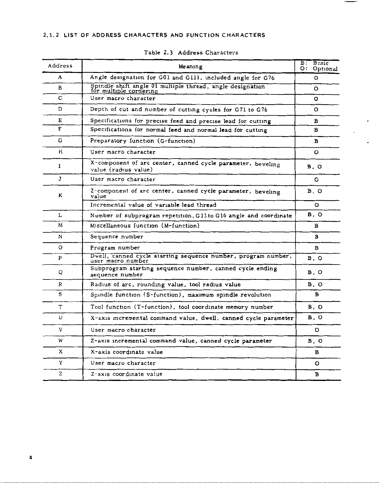
2.1.2
LIST
OF
ADDRESS
CHARACTERS
AND
FUNCTION
CHARACTERS
Address
A
B
c
D
E
F
G
H
1
J
K
L
M
Angle
Spindle
for
User
Depth
Specifications
Specifications
designation
shift
multiple
macro
of
cut
Preparatory
User
macro
X-component
(radius
value
User
macro
Z-component
value
Incremental
Number
of
Miscellaneous
Table
angle
cornering
character
and
number
for
precise
for
normal
function
character
arc
of
value)
character
arc
of
of
value
subprogram
function
tor
G01
01
multiple
___
(G-function)
center,
center,
variable
2.3
Address
Meaning
and
of
cutting
feed
feed
and
canned
canned
lead
repetition
(M-function)
Gill,
thread,
and
,
Characters
included
cycles
precise
normal
cycle
cycle
thread
G
13
to
angle
G
angle
designation
G71
for
for
lead
for
lead
parameter,
parameter,
16
angle
for
to
cutting
cutting
beveling
beveling
and
G76
G76
coordinate
B:
O:
Basic
Optional
O
O
O
O
B
B
B
O
B.
O
B,
O
B,
B
O
O
O
N
O
P
Q
R
S
T
U
V
W
X
Y
Z
Sequence
Program
Dwell,
user
Subprogram
sequence
Radius
Spindle
Tool
X-axis
User
Z-axis
X-axis
User
Z-axis
number
number
canned
macro
number
arc,
of
function
function
incremental
macro
incremental
coordinate
macro
coordinate
cycle
number
starting
rounding
(T-function)
character
character
starting
sequence
(
S-function)
command
command
value
value
value,
,
sequence
number,
tool
,
maximum
tool
coordinate
value,
value,
number,
radius
dwell,
canned
canned
value
spindle
memory
canned
cycle
program
cycle
revolution
number
cycle
parameter
number,
ending
parameter
B.
B,
B,
B,
B.
B,
B
B
O
O
O
B
O
O
O
O
B
O
B
4
Page 15

E1A
Code
ISO
Code
Table
2,4
Function
Characters
Function
Remarks
Blank
BS
Tab
CR
SP
ER
UC
LC
2-4-5
0
a
bits
2-4-7
bits
+ +
to
9
z
to
/
Del
NuL
BS
HT
LF/NL
CR
SP
%
(
)
to
0
to
A
/
DEL
Error
Disregarded
in
significant
in
ISO
data
area
in
EIA
Disregarded
Disregarded
stop
(comment
out
(comment
in
User
characters
block
(Including
(EOB)
User
skip
end)
macro
macro
start)
operator
operator
All
Mark)
EIA:
Special
code
of
End
Disregarded
Space
Block
Rewind
Upper
Lower
shift
shift
Control
Control
Disregarded,
Minus
9
Z
Numerals
Address
sign,
Optional
Disregarded
Parameter
starting
*
r
(
3
$
?
Notes:
1,
Characters
2.
Information
3.
Tape
code
#
*
t
3
$
?
other
between
(EIA
or
than
ISO)
Decimal
Sharp
Asterisk
Equal
Left
bracket
Right
User
User
User
the
Control
is
point
(Variable
(Multiplication
mark
bracket
macro
macro
macro
operator
operator
operator
above
cause
Out
and
automatically
designation)
operator)
error
Control
in
In
recognized.
significant
is
ignored
EIA:
area.
data
as
insignificant
Special
code
data.
5
Page 16

2.1.3
Numerals
as
the
coordinates
can
They
Decimal
dress
Coordinate
Angle
words.
words
Feedrate
Time
words:
EXAMPLE
5.
-
XI
20.
5
Y
IG99)F.
(G98)F25.6—
G04P1.-
Normally,
inputted,
(or
0.0001
ter
setting
as
1"
"
to
parameter
2.1.4
the
In
becomes
CRT.
•
When
•
When
the
While
on
the
neglected.
the
MEM
dicates
of
end
2.1.5
During
read
lor
blocks
in
for
can
BUFFER
in
the
the
In
of
advance
the
contain
DECIMAL
containing
dimensional
(distance),
inputted
be
points
words.
•
word:
U,
X15.000
Y20.500
FO.
2*
—
(for
F25
(for
Dwell
-
when
the
control
inch
,
the
(or
mm
1
#6019D6.
LABEL
following
the
the
punched
the
the
normal
advance
follow-on
next
SKIP
effective,
power
RESET
label
When
(memory)
presence
part
tool
or
data
and
operation
up
POINT
a
data
can
be
X,
,
B
A
F,
E
P
[
mm
mm/rev
20
32
F
mm/rev
50)
F
.
1
data
without
or
control
inch
1
FUNCTION
cases
and
supply
operation
function
skip
up
tape
LSK
or
of
program.
RECISTER
operation,
and
compensation
operation.
radius
up
to
compensation
to
128
characters
PROGRAMMING
decimal
of
angle,
from
used
Z,
]
mm
mm
)
000
regards
1
deg.),
may
or
the
LSK
to
is
EDIT
a
point
addresses
time
punched
in
the
K,
I,
or
X15.0000
or
Y20.5000
or
F0.2000
(for
F25.
or
(forF32)
sec
decimal
a
"1"
but
be
0.001
label
displayed
is
is
turned
is
effective,
is
the
first
displayed
(editing)
pointer
one
block
R
(inch
as
made
deg.).
skip
executed.
at
is
compensationÿ
4
blocks
is
executed.
of
computing
including
may
related
and
speed.
tape
following
1
in.
in.
in./rev
F24)
60
in
point
0.001
with
to
interpret
function
on.
EOB
on
the
mode,
the
leading
of
data
computed
mode,
are
data
required
One
be
or
/min
mm
a
parame-
Refer
on
the
all
code
CRT
is
two
read
block
EOB.
used
to
MDI.
ad¬
is
data
it
in¬
are
The
are
not
•
MOO.
•
codes
M
mandnijs
2.1.6
A
high-speed
standard
consecutive
cutting
time
stop
this
function
ous
thread
ed
stop
NOTES:
This
1.
where
Programming
2.
Block-to-block
quired
not
is
this
Function
ation
mode,
blocks
read
M01
HICH-SPEED
in
\U)2.
.
maximum)
(6
to
stop
including
advance.
buffer
serve
to
group
(G32)
or
between
(Note
cutting
time
between
function
the
control
to
compute
eliminated
stopping
(M93,
of
consecutive
inter-block
M30
ad\
for
of
linear
blocks
a
is
for
stop
time,
set
aiu
BUFFER
register
high-speed
blocks
interpolation
2).
This
smooth
blocks.
effective
is
provided
Circular
time
tool
or
use
M92)
blocks
stoppage
the
following
by
parameter
e-readmg
RECISTER
is
is
specified
reduced
is
permits
cutting
for
Interpolation
due
radius
remains.
2.7.4
(optional).
up
.
installed
cutting.
(G01),
to
in
with
G22
and
with
to
the
compensation
To
Buffering
When
to
5
time
is
M
codes
com
as
in
thread
zero
continu¬
shorten¬
G23
Radius
time
reduce
in
M93
reduced
the
If
a
the
by
option
re¬
oper¬
zero.
PROGRAM
2.2
NUMBER
AND
SEQUENCE
NUMBER
2.2.1
Program
for
Up
character
program
trol,
ploying
One
ends
in
placed
placed
ER
parts
NOTES:
1.
the
to
and
program
with
*0
<
PROGRAM
PROGRAM
(or
The
/M02;
of
PROCRAM
numbers
purpose
4
digits
"0"
numbers
up
an
option.
M02,
the
at
at
the
0.
1
%
ISO
at
of
the
tape.
blocks
,
/M30;
programs.
may
as
to
199
begins
M30
end
end
WITH
NO.
for
NUMBER
may
of
program
be
program
can
or
with
or
of
main
of
subprograms.
it-
MO
2.
if-
10
code)
optional
,
/M99;
be
written
be
registered
999
M99.
0
1
is
punched
are
prefixed
numbers.
a
programs,
to
programs
identification.
after
an
address
to
Up
in
can
be
registered
program
M02
number,
and
and
4.
3
2
-------
-----
PROGRAM
PROGRAM
block
not
WITH
NO.
on
both
skip
regarded
the
M30
M
1234
such
are
M99
9
9
99
con¬
,
%
end
as
em¬
and
is
as
enc
6
Page 17

2.
It
(#6201Do).
and
to
as
2.2.2
Integers
ten
following
numbers.
Sequence
blocks,
meaning
Therefore,
tial,
and
any
sequence
sequential
numbers.
When
searching
to
search
.
hand
NOTES:
1.
Five
sequence
is
possible
ineffective
M99
make
the
a
sign
SEQUENCE
consisting
an
numbers
and
do
sequence
and
they
duplicated
numbers
or
specify
more
or
with
to
make
succeeding
of
program
NUMBER
address
not
may
number
for
digits
number.
a
the
as
of
up
are
reference
have
of
sequential,
be
numbers,
is
are
convenient
sequence
program
must
parameter
reading
a
program
ER
end.
to
4
digits
character
any
influence
machining
also
possible.
numbers,
numbers
not
change
(EIA)
N
numbers
as
be
M02,
of
end,
and
(ISO)
or
%
may
be
sequence
as
for
on
the
processes.
non-sequen-
using
not
Generally,
sequence
sure
be
before¬
written
M30,
writ¬
as
2.3
COORDINATE
Generally,
tions
are
tems
words
axes
and
directions
2.3.1
Address
dinate
Axis
Main
Radius
Value
for
Circular
a
Interpola¬
tion
commands
commands
and
called
consist
coordinate
of
numerals
.
COORDINATE
of
Coor¬
Words
X,
Z
U,
W
I,
K
R+
WORDS
for
setting
for
address
representing
WORDS
Absolute
target
Incremental
(U:
Direction
W:
Direction
Incremental
point
start
circular
(I:
X-axis
K:
Z-axis
Radius
movements
words,
characters
Meaning
coordinate
position
distance
distance
and
arc.
component
component)
value
of
in
coordinate
and
coordinate
for
dimensions
position
X-axis,
in
Z-axis)
in
center
circular
axis
direc¬
sys¬
desired
of
between
of
,
arc
of
2.
When
quence
read,
3.
Blocks
be
searched
data
2.2.3
Those
cluded
that
switch
OPTIONAL
blocks
are
block,
for
EXAMPLE
12
When
the
neglected,
this
block
1234
N
"l,"
With
NOTES:
The
1.
ed
while
buffer
read,
to
skip
While
2.
this
The
3.
and
two
number,
and
without
contained
in
neglected
when
that
N1234
switch
and
is
read
G01
"1"
optional
the
resister.
subsequent
the
reading
function
block
1
/
i$
or
no
which
number
G01
when
may
blocks
skip
basic
a
more
only
more
sequence
for
with
in
BLOCK
the
X100
for
12
as
X100,.
be
block
blocks
or
ineffective.
is
12
blocks
one
searching
respect
the
blocks.
SKIP
"In"
between
external
"n"
/3
on,
is
switch
the
if
omitted.
skipping
are
Once
switching
.
punching
9
/
-
one.
have
is
numbers
(n
In
optional
on.
is
the
being
the
an
is
retrieved
is
to
(/l
(1-9)
=
and
Z200;
for
process
blocks
on
out
option
the
same
performed.
can
address
the
19)ÿ
-
the
block
entire
3
is
/
into
read
have
ineffective
is
programs,
function,
and
also
is
in¬
end
block
on,
is
se¬
of
skip
is
execut¬
the
been
Note:
and
X
follow
For
cremental
2.3.2
The
control
Z-axis.
axes,
two
axes
mands,
2.3.3
OUTPUT
2.
3.
3.1
The
minimum
punched
by
Metric
Inch
X-axis
When
Z
are
G90
not
according
details,
refer
Inputs.
SIMULTANEOUS
provides
Number
when
,
movement
LEAST
INCREMENT
Least
of
commanded
and
X
will
INPUT
Input
input
or
tape
Least
system
system
is
specified
0.
0.0001
G91
and
as
fixed
to
to
simultaneously
.
Z
absolute
G90/G91
2.3.5
CONTROLLABLE
two-axis
the
in
the
For
not
occur
INCREMENT
Increment
units
that
are
MDI
Input
1
001
Increment
x
mm
in.
diameter.
for
used,
are
designation.
Absolute
control
same
axis
can
shown
s
10
0.01
0.001
addresses
value
and
AXES
for
controllable
block,
without
LEAST
AND
commanded
be
below.
(
times
10
input
mm
in
and
X-
is
unit)
In¬
and
com¬
7
Page 18

2.3.3.
Inch
1
/MM
Inch/MM
Selection
parameter
by
loo!
ol
(or
mm
these
In
eration
NOTES
1.
units.
0.01
•
Programming
•
Write
•
Programming
•
Program
If
NC
into
mm
times
the
ll
contents
the
tenth
3.
When
the
out
the
Multiplication
A.
unit)
It
does
time,
10X
same
depending
EXAMPLE
G04
GOO
Least
input
input
of
value
I
set
0.0001
mm
increment
must
operation
editing
:
tape
or
stored
increment,
the
increment
machine
of
the
tape4-,
stored"
"as
increment
is
not
angle,
set
is
address
U--.
•
•
L
is
Increment
selected
Input
selection
multiplication
#6006D5-
must
inch)
,
and
made
be
for
for
programmed
intended
of
the
stored
the
effective
function
as
on
,«
in
operation
in
MDI
operation
operation
an
in
the
system
NC
tape
move
will
commanded
program
stored
regardless
system.
factor
for
etc
effective
word
type
Not
—
Multiplied
by
by
G20/G21
factor
always
offset
system,
the
unit
mode.
by
equipment
machine
dimensions.
is
are
stored
by
dimensions.
figures
10X
distance
on
the
When
multiplication
(#6006D5
multiplied
is
command.
of
G
multiplied
(Cont'd)
setting
xl/xlO
be
is
the
in
TAPE
in
MEMORY
m
EDT
0.001
will
switched
ten
punched
is
of
(10
designation
10
by
#6OO1D0.
is
written
possible
following
of
0.01
mode.
mode.
mm
set
move
in
memory,
times
punched
are
switching
times
command
1),
=
by
10
by
(Distance)
optional.
is
made
in
mm.
mode.
is
by
0.01
ten
when
one
or
out
the
input
factor
the
or
10
(Time)
0.001
in
op¬
fed
the
on
of
only.
of
not
2.3.4
Maximum
are
MAXIMUM
programmable
shown
Maximum
Metric
Output
Inch
Output
In
absolute
must
axis
value.
PERLY
MUM
The
apply
in
The
mum
2.3.5
Both
be
•
THE
IF
PROGRAMMABLE
above
to
distance
addition
accumulative
accumulative
Maximum
Metric
Inch
Note:
least
These
output
ABSOLUTE
absolute
used
for
Absolute
and
X
Z
EXAMPLE:
PROGRAMMABLE
below.
Metric
Inch
input
Metric
Inch
input
programming,
not
exceed
MACHINE
MOVE
A
maximum
move
to
system
system
values
increment.
input
the
control.
input
is
.
•
X-
values
Programmable
input
input
move
the
maximum
MAY
COMMAND
VALUE
programmable
command
command
must
value
values
shown
Accumulative
±99999.999
±9999.9999
are
AND
INCREMENTAL
and
specified
•
•
Z-
DIMENSIONS
move
of
Values
±8388.
±320.
607
2601
±21307.061
•±838.8607
amount
programmable
NOT
FUNCTION
OVER
IS
GIVEN.
values
addresses
addresses
not
exceed
below.
Values
not
determined
incremental
the
by
command
mm
in
mm
in
of
THE
I,
K,
X,
the
mm
in
INPUTS
input
addresses
each
PRO¬
MAXI¬
also
R
U,
maxi¬
by
can
W.
2.
Least
luo!
s',
Inch
#60071)
8
3.
3.
motion.
stem
Metric
Inch
2
output
is
output
or
j.
Least
made
output
metric
Output
increment
Selection
by
Least
(Radius
0.
0.00005
output
Increment
is
of
parameter
Output
X-axis
0005
mm
selected
is
the
minimum
metric
(#6007D3).
Increment
value)
in.
system
0.001
0.0001
by
unit
or
Z-axis
mm
parameter
inch
in.
of
•
Incremental
U
es
EXAMPLE:
•
Absolute
used
EXAMPLE:
and
m
one
W.
input
input
U---
block
X-
U-
and
•
•
•
is
specified
•
•
W
•
incremental
mixedly.
•
W-
Z--.
by
;
input
the
address¬
be
can
Page 19

NOTE:
and
tive
When
addresses
W
are
used
in
one
.
X
block,
and
the
U
or
latter
addresses
is
effec¬
Z
The
center
addresses
must
dimension
I
be
.
and
specified
K
for
designation
by
the
incremental
of
arc-
and
X
U
and
Note:
values
the
Fig.
Address
2b
2b
2
ill
2
Z:
W:
Since
diameter,
in
half
of
2.1
Incremental
X
Z
U
W
I
K
R*
Hi
2
Hi
2
Hi
2
I
Absolute
Incremental
X
and
the
values.
Absolute
Increment
System
Absolute
Input
Incremental
Input
Incremental
Input
Incremental
Input
+x
W,
Zj
Input
U
are
the
Coordinate
Coordinate
w>
2,
z,
Input
designated
actual
Designation
Diameter
Diameter
W,
movement
Values
Values
Radius
by
and
the
is
Table
2.
5
Position
Position
Move
Move
Distance
point
ing
Distance
ing
point
Direct
As
effective
TAPE,
MEM
modes
MDI
mode
EXAMPLE:
Incremental
•
in
X-axis
Z-axis
in
in
in
of
of
in
in
X
arc
Z-axis
arc
axis-direction
amount
amount
programming
G
code
G90
G91
shown
below,
only
Addresses
Auxiliary
interpolation
Meaning
direction
direction
X-axis
Z-axis
to
to
to
X,
Z
U,
W
X,
Z
U,
W
G91
move
data,
direction
direction
center
direction
center
circular
of
Absolute
Incremental
G90
addresses
GOO
command
I,
always
are
(Note)
from
from
arc
Meaning
G91
and
X
command
G90
Absolute
Incremental
Absolute
Incremental
X40.
etc.,
R,
K,
incremental
(Note)
start¬
start¬
command
command
commands
Z
and
;
Z50.
of
are
.
command
G91
Incremental
Incremental
influ¬
Not
enced
90
and
G
circular
commands.
by
G91.
Cases
mental
*
When
selected,
where
commands)
special
G90
G90
G
and
and
are
code
G91
used.
G91
(basic)
I
(absolute
codes
or
can
and
II
(option)
be
incre¬
used.
can
G91
and
the
is
G90
in
the
block,
same
.
G01
fltective,
incremental
same
the
G90
and
NOTE:
together
is
in
effective
EXAMPLE.
Gÿl
become
block.
in
in
not
one
X80.
this
both
be
If
written
G
block,
the
91
programmed
are
they
later
;
ZfeO.
commands
Z
and
X
written
only
axes
is
.
9
Page 20

2.3.6
X-AXIS
DIAMETER/RADIUS
SWITCHING1-
2.4
RAPID
TRAVERSE
RATE
Addresses
are
specified
diameter
with
ped
addresses
the
diameter
bolh
made
by
O'
Diameter
1:
Radius
+x
X.
(a)
In
the
ameter
Address
command
Address
command
X-axis
display
Tool
position
offset
Tool
data
coordinate
system
Nose
Feedrate
in
tion
value
coordinate
for
radius
X-axis
Radius
for
R
circular
interpolation
90
G
G
Parameters
cornering,
70
G94
-
G
-
multiple
D,
ing,
Q,
P,
R
X
and
by
designation.
DIAMETER
X
and
the
setting
designation
Resignation
2
x>
case
Designation
X
U
position
work
R
F,
E
direc¬
,
I
data
,
76,
for
and
corner¬
,K,
I
U
for
diameter
/RADIUS
can
be
radius.
of
of
Di¬
Fig
Table
Diameter
Programming
Diameter
Diameter
mental
Diameter
Diameter
Diameter
Radius
Radius
Radius
Radius
Radius
X-axis
value.
When
the
used
The
parameter
+x
(b)
.
2
2.
2.6
value
incre¬
value
value
value
value/min
value
value
coordinate
This
control
switching
for
designation
switching
#6006D3.
X«
In
the
dius
Programming
Radius
Radius
incremental
value
value
value
value
/rev
words
is
called
is
equip¬
option,
is
X.
HZ
—
case
of
Designation
Radius
value
value
_
of
ra¬
2.4.1
2.
4.
1.1
The
rapid
for
the
the
Manual
erse
rates
dependent
determined
rapid
are
traverse
set
axes.
each
in
these
in
other,
ent
times
override
100%
4.
1.2
are
For
paths
For
and
available.
parameter
2.
U)
set
(p:
(2)
The
upper
The
listed
limit
Refer
for
2.4.2
G
and
code
G
FEED
E
function
code
G99
G98
Note:
Function
Since
F,
effective
However,
must
code
RAPID
Rapid
traverse
Positioning
Rapid
differ
on
by
parameters
by
When
the
axial
direction
axial
and
the
among
normally
rapid
of
the
Fo
(#6231).
Range
each
at
some
Least
rapid
limit
Metric
Inch
upper
values.
set
is
to
the
definite
FUNCTION
listed
below
Designation
Designation
For
the
Designation.
E
codes
until
when
be
designated.
TRAVERSE
Traverse
motion
(GOO)
Traverse
among
the
machine
the
machine
rates
determined
tool
is
directions
end
points
these
not
traverse
basic
constant
a
Rapid
rapid
rapid
is
of
axis,
suitable
output
traverse
shown
Input
Input
for
limit
The
according
the
machine
value.
must
is
commanded.
details,
modal,
are
F,
next
G98/G99
RATE
Rate
is
used
for
and
(RAPID).
axes
the
since
specification
tool
builders.
by
in
advance
moved
in
rapid
simultaneously,
are
independent
are
reached
motions.
straight.
Therefore,
rates,
traverse
feed
rate
Traverse
traverse
multiple
increment)
can
rate
below.
24,000
2,400
X-axis
optimum
(F-
be
Function
of
feedrate
of
feedrate
refer
to
the
builder's
tool
AND
designated
to
speed
value
machine.
these
E
codes
are
are
switched,
for
the
the
motion
motion
The
they
and
The
the
machine
for
individual
traverse
motions
of
at
differ¬
Fo,
25%,
rates,
set
by
Rate
rates
can
of
be
2.8.29
codes
p/sec.
125
to
set
/min
mm
m/mm
is
half
of
upper
manual,
E-FUNCTION)
before
mm
in
mm/min.
/rev.
Feed
in
are
given.
new
for
trav¬
are
are
each
motion
50%
are
a
be
the
the
F,
F
10
Page 21

2.4.
:i)
(2)
2.1
Tool
be
feed)
The
the
Feed
Per
feed
specified
.
feed
F
andEcodes
per
with
ranges
Revolution
revolution
(normal
F
that
are
can
as
(C99
the
of
feed)
be
follows.
Mode)
spindle
or
specified
EXAMPLE
F200
case,
/rev.
;
•
;
•
In
case
of
F32.
feedrate
the
x
350
+x
is:
rpm
can
(fine
E
by
G99
G01
In
F
x
the
S
U10000
above
=2.0
mm
(rpm)
S350
Metric
output
Inch
output
These
restrictions
Metric
Inch
Notes
I.
2.
NOTES:
A
1.
2.
Any
F
not
EXAMPLE
Mode,
G99
Metric
input
Inch
input
Metric
input
Inch
input
feed
ranges
depending
output
output
.
Program
a
range
the
Refer
minus
operate
F-250
12,000
upper
performance
to
below
This
command
commands.
F
Format
F32
E34
F24
E26
F32
E34
F
24
E26
are
F(E)
F(E)
feed
that
limit
the
"F0"
value
If
properly.
;
E
and
Range
Feed
of
F0.01-F500.00
E0.
0001
.
FO
0001
E0.
000004
.
FO
01
E0.
0003
_
F0.
001-F50
F0.
000010
subject
the
on
S
x
=
S
x
=
revolution
per
X-axis
the
may
limit
or
still
of
tool
data
not
mm/min
machine
causes
should
specified,
Wrong
Ranges
feed
-
E5CO.OOOO
F19.6850
-
E19.
-
F1270.00
-
E1270.
-
-
to
the
spindle
24,000
2,4000
within
component
1,200
be
machine.
the
builder's
errors.
be
the
/revolution
/rev
mm
mm
/rev
ini
rev
685000
in
/rev
mm/rev
0000
mm
/rev
.0000
in
rev
7:
.000000
E50
in
l
Jrev
following
speed
mm/min
ln/min
remains
/mm.
in
reduced
specified
machine
S.
such
by
manual.
for
will
7
4.
700
m/ain
•
Values
of
terpolation
when
EXAMPLE
two
G99
S100
U60.
G01
the
In
S
x
F
EXAMPLE
G99
G03
the
In
F
x
F
axes
1
above
=0.5
500
=
/
=
S1000
U---
above
S
=
21
S
command
represent
are
(rpm)
W40.
case
mm/rev
mm/min
+
3002
r-
LX-axis
TANGENTIAL
YUStU.VL/'
/Zoo
2
(rpm)
W--
case,
0.2
/rev)
(mm
mm/min
200
>/fx2
at
linear
the
tangential
simultaneously
;
;
F50
,
the
feedrate
1000
x
4002
T~
Lz-axis
feedrate
y'
I
100
,
MM/MIN
(a)
;
F20
feedrate
the
x
+
fz2
or
circular
rpm
feedrate
component
MM/MIN
;
1000
(rpm)
nxDRATE
700
MM
/MIN
feedrate
controlled.
is
component
is:
in¬
3.
Feedrate
X-axis
commands
must
be
given
the
the
in
direction
radius.
in
of
CENTER
X
"'ÿ00
I
\
!«/HIN
l
,
fx
wfT
(b)
+i
11
Page 22

2.4.2.
(1)
(2)
Metric
Output
Inch
Output
Notes
1.
2.
NOTES
Do
1.
values
Commands
2.
speeds
EXAMPLE
2
Feed
Tool
feed
/mm
feed
F
G
Metric
with
codes
98
Mode
in
The
with
Input
Inch
Input
Metric
Input
Inch
Input
.
Program
the
X-axis
ceed
half
EXAMPLE
G01
G
96
(Metric
The
upper
the
not
C°S
G01
limitation
builder’s
to
is
write
in
20000
X
to
performance.
tool
value
Per
Minute
F
be
codes.
is
F
specified
that
as
Code
Range
can
range
Format
F50
32
F
F50
42
F
feed-per-minute
above
U
300.
component
value
speed
the
output,
limit
imposed
Refer
manual.
set
be
F
in
radius
command
X-axis
the
in
F700
(C98
can
follows.
Feed
FI.
-
F0.01
-
FI.
F0.01
upper
F12QQ0
metric
is
to
This
parameter
m
;
Mode)
in
be
programmed
Range
of
feed
24000.
F
F944.8
-
F60960.
F24000.00
-
values
will
limit
,
input)
further
by
the
of
the
upper
FO
direction
mm/min
per
mm/min
in
mm/min
in/min
so
not
feedrates.
subject
machine
machine
#6228.
or
negative
indicate
minute
that
ex¬
limit
or
EXAMPLE
G'tS
G01
In
F
(mm/min)
EXAMPLE
G98
G03
In
F
2,4.3
1
,
U
3000
case,
this
500
=
=
2
;
X---
case,
this
200
=
=
AUTOMATIC
/
DECELERATION
Acceleration
and
for
cutting
without
programming.
W4000
3002
Z
fx2
X
+
and
*-Y-axis
CENTER
feed
F500
+
40O2
L
X-axis
component
\+
400
MM/MIN
(a)
F200
2
+
fz
MM/MIN
(b)
<w
ACCELERATION
deceleration
are
automatically
300
!
1
!ÿ
component
MM/MIN
;
Is
I
for
rapid
AND
traverse
performed
F
700
*
Values
interpolation
when
rate
trolled
12
nc/rain
of
.
F
command
represent
two
axes
at
linear
the
are
simultaneously
circular
or
tangential
FEEDRATE
700
MM/MIN
feed-
con¬
2.4.3.
Traverse
the
In
matic
(See
Fig.
•
Positioning
Manual
•
Manual
•
Manual
1
Acceleration
And
following
acceleration
2.3.)
(GOO)
rapid
continuous
HANDLE
Manual
operation,
and
traverse
feeding
And
Deceleration
Feed
the
deceleration
(RAPID)
feeding
(HANDLE)
pattern
(JOG)
is
of
of
linear.
Rapid
auto¬
Page 23

v
EXAMPLE
VELOCITY
Rapid
eration
set
by
2.4.3.
Cutting
the
In
matic
tential
•
Cutting
traverse
constant
parameter.
2
Acceleration
Feed
following
acceleration
curve.
feed
V
VELOCITY
rate
of
operation,
(See
(G01
F.
coo
TIME
Fig.
and
rapid
(#6280
And
and
Fig.
to
2.3
the
acceleration
traverse
#6287)
to
Deceleration
the
deceleration
2.4.)
G03)
rate
pattern
is
can
of
of
of
/decel¬
be
auto¬
expo¬
GOO
G01
GOO
G01
NOTE:
Sll
X->
Z-
X--
X-
Z---
S22
X--.
M03
•
Z-.
••
F
Z-.-
•••
M03
Z-
F-..
;
Z
The
machine
issued
is
;
command
•
S
Spindle
;
•
•
M05
Spindle
i
•
:
;
•••
F...
two-digit
when
.
CW
:
stop
;
BCD
S
and
Sll:
Sll:
S22
i
output
two-digit
Effective
Effective
:
Effective
sent
is
to
command
the
Feedrate
vals
parameters.
by
NOTE:
parameters
respective
unless
2.5
time
feedrate
and
automatic
The
are
machines.
required
is
it
SPINDLE-SPEED
(S-FUNCTION)
spindle
each
block,
a
design
S
the
(rpm),
move
a
is
executed
or
after
to
2-DICIT
speed
address
S
code
command
execution
and
the
machine
2.5.1
The
lowing
For
speed
manual.
When
in
tool
mand
mand
Refer
TIME
Fig.
constants
is
bias
(#6092,
acceleration
set
to
the
Do
for
PROCRAMMINC
is
specified
(S00
S
and
its
refer
to
the
and
will
construction
together
the
completion
tool
2.4
at
2
at
2kpps
are
set
#6093)
set
/deceleration
optimum
not
special
values
change
application.
FUNCTION
two
by
S99)
to
corresponding
machine
an
depend
with
builder's
.
code
S
on
(Whether
the
of
tool
tool
manual.
inter¬
msec
intervals
for
the
setting
digits
spindle
builder's
are
issued
the
machine
the
com¬
move
movement).
S
the
fol¬
com¬
2.5.2
(1)
(2)
s
S
4-DICIT
digits
Four
specify
to
When
M04
with
to
the
reaches
details,
manual
S
M03
(reverse
next
.
EXAMPLE
S1000
START
THE
PROGRAMMING
following
spindle
the
command
(spindle
running),
block
the
speed
to
refer
;
M03
RPM
1000
I
I
START
%
OF
BLOCK
is
given
forward
after
given
the
A
(StUDDD)
S
speed
in
a
in
running)
control
the
the
spindle
the
by
machine
ACTUAL
SPEED
COMPLETION
COMMAND
M
+
rpm.
block
S
tool
SPINDLE
are
together
or
proceeds
speed
code.
builder's
OF
used
the
For
-
i
13
Page 24
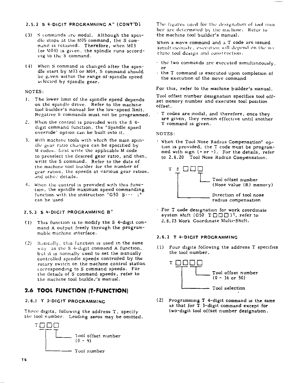
2.5.2
(3)
S
(4)
NOTES:
1
.
The
on
too!
Negative
2.
When
digit
override"
With
3.
dle
M
to
write
the
gear
and
4.
When
tion,
function
can
S
4-DICIT
commands
dle
stops
mand
(or
M04)
to
ing
When
start
dle
be
g.ven
st
Iccted
lower
the
builder's
command
machine
gear
codes,
preselect
the
machine
ratios,
other
the
the
be used
PROGRAMMING
are
the
at
is
retained.
is
gi\en,
theScommand.
S
command
MQ3
by
within
by
spindle
of
limit
S
commands
control
option
tools
first
the
S
command.
tool
the
drive.
manual
function,
changes
write
desired
speeds
spindle
the
ratio
details.
control
spindle
with
the
modal.
command,
M05
Therefore,
the
is
changed
M04,
or
the
range
gear.
the
spindle
for
must
provided
is
can
be
with
the
builder
is
provided
maximum
instruction
Although
spindle
S
of-spmdle
Refer
the
not
the
built
which
can
be
applicable
gear
Refer
for
various
at
speed
(CONT'D)
A"
the
when
runs
after
command
speed
to
the
low-speed
be
with
"Spindle
into
the
specified
ratio,
the
to
number
the
with
commanding
"G50
the
spin¬
S
com¬
M03
accord¬
the
spin¬
should
speed
depends
machine
limit.
programmed.
4-
S
the
speed
it.
main
spin¬
by
code
M
then,
and
of
data
of
ratios,
gear
this
func¬
S--'
The
fiaurob
ber
arc
the
machine
When
sinnilt
chine
•
the
or
the
the
this,
For
Tool
set
memory
offset
T
codes
are
T
command
NOTES:
•
When
tion
med
to
determined
a
move
meouj.lv.
tool
two
T
command
execution
offset
.
given,
the
is
with
2.8.20
t
T
used
tool
command
design
commands
refer
number
number
are
modal,
they
is
Tool
provided,
sign
Tool
for
builder's
execution
and
is
of
the
to
the
designation
remain
given.
Nose
(+
or
Nose
L_
tin-
by
the
and
const
are
executed
executed
move
machine
and
executes
and
Radius
the
T
-)
.
Radius
Tool
(Nose
Direction
radius
designation
machine.
manual.
code
T
a
depend
will
ruction
upon
command
builder's
specifies
therefore,
effective
Compensationt
code
must
For
the
Compensation.
offset
value
of
compensation
of
VH>1
1
mini
Keler
are
on
to
issued
the
.
simultaneously,
completion
manual.
tool
tool
until
be
details,
number
(R)
tool
position
once
off¬
they
another
op¬
program¬
refer
memory)
nose
mi
of
2.5.3
(I)
(2)
2.6
2.6.1
Three
the
4-DIGIT
S
function
This
A
mand
mable
machine
Basically,
as
way
is
it
but
controlled
rotary
corresponding
details
the
machine
the
TOOL
T
3-
DIG
digits,
tool
number.
T
TT
PROCRAMMINC
to
is
output
freely
interface.
function
this
the
S
4-digit
normally
used
spindle
the
of
on
to
S
tool
S
command
builder's
switch
FUNCTION
IT
PROGRAMMING
following
Leading
1
ool
(0
-
B
modify
the
through
used
is
command
to
set
speeds
controlled
machine
command
speeds.
speeds,
manual.
(T-FUNCTION)
the
address
zeros
may
offset
9)
number
+
S
4-digit
the
in
A
the
control
T,
be
program¬
same
the
function,
manually
by
station
For
refer
specify
omitted.
com¬
the
to
•
For
system
2.8.23
2.6.2
(1)
(2)
code
T
designation
shift
Work
T
4-DIGIT
Four
digits
tool
the
number.
T
Programming
as
that
for
two-digit
(G50
T
Coordinate
PROGRAMMING
following
Tool
(0
Tool
T
4-digit
T
3-digit
tool
offset
for
work
Multi-Shift.
address
the
offset
16
or
-
selection
command
command
number
coordinate
refer
to
T
specifies
number
50)
the
is
except
designation.
same
for
14
Tool
number
Page 25

(3)
For
applicable
refer
to
the
Specifications
a
b
tool
machine
number
tool
Tool
to
builder's
Offset
0-16
0-50
be
specified,
No.
manual.
(3)
Write
to
ing
control.
4.3.5
to
Values.
Memory,
6.2.3
these
operate
For
Displaying
For
follow
Work
data
the
the
the
in
machine
writing
writing
the
procedure
Measurement
memory,
and
into
under
procedure,
Writing
Tool
Coordinate
described
Value
before
automatic
Tool
Direct
start¬
refer
Offset
in
Input+.
NOTES:
When
1.
command,
tool
should
from
might
2.
Tool
offset.
2.6.3
area
The
radius
data
tion
(1)
,
WORK
SHIFT
<1
TOOl
M1MUK'
i
Hour*
TOOL
>
MEMORY
CROUPS
TOOL
•
(19
TOOL
.
MEMORY
NOTE:
above
builder's
(2)
the
instantaneously.
be
area
the
occur.
offset
TOOL
compensation
in
OFFSET
which
are
entire
The
including
COORDINATE
MF.MORY
l.ROlP)
OFFSET
(:0
)
MA>
COORDINATE
(
10
1
MAX
WEAR
MEMORY
CROUPS
MAX.7*-'
RADIUS
For
the
Offset
manual.
"tool
The
function
memory
for
various
tool
coordinate
work
coordinate
tool
selection
work
coordinate
function,
ent
tool
number
a
turret
removed,
where
number
tool
stored
memory
the
options
r
I
No.
00
f
01
09
10
1
J$.
1
50
51
80
81
99
actually
Memory,
offset
directly
Nos.
compensations.
lathe
0or00
MEMORY
position
values,
called
is
orrsE7
_
X
1
i
:
1
1
refer
Nos."
correspond
and
memory
system)
Nos.
slntt
not
is
Therefore,
before
accidental
an
areas
are
MEMORY
2
usable
their
m
the
memory
related
changed
begins
the
cancels
+
offset
other
and
Offset
Offset
of
shown
as
NO
R
7
range
the
to
specified
contents
Nos.
correspond
T
tunc
the
to
by
to
index
the
command,
collision
the
values,
compensa¬
Memory
Memory
below.
I
T
3-DICIT
T
BASIC
r
T
STAND,'
P
OFFSET
MEMORY
h
SUPPLEMENT
J
within
machine
by
to
the
are
However,
(for
setting
lion.
is
an
function.)
T
the
T
the
turret
tool
tool
.
<.-D!C!T
IRD
the
tool
T
the
"offset
used
the
the
the
to
The
independ¬
2.6.4
When
set
is
the
TOOL
the
value
added
program
position.
coordinate
the
actual
memory
When
has
sons,
set
the
changed
the
again.
attained
(1)
Range
The
is
Output
Metric
Output
Inch
Output
(2)
Sign
a.
Store
Offset
viation
reference
-z
POSITION
offset
tool
corresponding
algebraically
and
Therefore,
values
tip
tool
in
advance
coordinate
due
tool
position
Thus,
without
of
tool
programmable
shown
Metric
Inch
Metric
Inch
of
the
Memory.
below
Input
tool
from
+
5
3
5
K
input
input
tool
tool
&
number
to
tool
the
the
the
of
must
the
as
value
tool
to
the
programmed
correcting
position
.
input
input
position
position
The
tool
the
which
X
+
\
tOC
TOOL
TION
-X
2.5
Fig.
OFFSETS
is
the
to
command
the
moved
is
difference
programmed
stored
be
offset
the
of
or
wear
offset
values
the
offset
range
Setting
0
*8388.607
-
*330
0
-
0
±9999.999
-
0
±838.8607
-
offset
offset
offset
position
tip
determined
is
-itf
RAMMED
POSI¬
specified,
offset
tool
to
into
value.
actual
some
machining
program.
value
of
tool
Range
2601
values
values
value
ACTUAL
TOOL
(6x.
2
the
value
offset
the
between
tool
tool
tool
other
should
offset
mm
in
mm
in
is
of
as
POSITION
DIAMETER)
off¬
number
in
the
and
tip
offset
tip
rea¬
be
is
value
the
in
the
the
zero.
de¬
15
Page 26

2.6.4
(3)
TOOL
Description
mentioned
As
the
by
offset
address
value
number
program
moved
When
the
Once,
the
until
the
the
is
difference
values
to
there
tool
the
tool
another
other
offset
compensated
.
OFFSET
(
T101
(+
<
TI15
(+
V
POSITION
tool
of
above,
T
corresponding
is
added
algebraically
the
offset
is
no
moves
moves
tool
only
offset
always
number
offset
value
for
between
VALUE
T
6Xi,
T
5X2,
+
+
OFFSETS
position
and
to
the
position.
move
by
number
is
changed,
by
the
6ZX)
5Z2)
when
4
digits
command
and
command
the
number
to
the
is
designated.
is
the
old
(CONT'D)
offset
tool
the
is
to
the
the
tool
in
offset
is
designated,
offset
designated
offset
the
amount
and
new
motion
specified
moved,
tool
value
tip
the
value.
position
of
the
offset
offset
m
is
block,
When
or
value
the
the
(5)
a.
Since
EXAMPLE
G50
X-..
GOO
S--
X--
Instructions
offset
position
Tool
the
actual
offset
tool
tool
tool
is
selection
starts
ing
the
Tool
T-code
the
the
corresponding
code
T
the
other
EXAMPLE
T0202
GOO
Z--
M03
T0108
z...
for
commanding
offset
offset
must
tool
is
code
;
to
to
modal,
is
•••
at
signal
move
the
starts
commanded.
T
;
is
executed
number
be
designated.
the
block
When
(BCD)
by
tool
it
designated.
The
tool
selected.
motion
to
ing
the
tool
Offset
made
motion
at
traverse
tool
position
by
corresponding
in
which
T-code
is
offset
the
offset
is
the
retained
number
is
made
number.
Tool
contents
offset
the
rapid
rate.
designat¬
is
fed
and
value
until
N02
offset
accord¬
of
number
is
to
the
read,
is
02.
16
(4)
+x
EXAMPLE
flOl
X
G01
T115
speed
Move
move
The
feedrate
the
by
block.
the
(GOO
or
or
the
in
number
.
£X>
(X
•
•Z-•
speed
G01
block
+<rz»!
2
+
Z)
;
F(E)
•
.
with
tool
of
command
Therefore,
F--0
containing
r
sZ1/
<52.
tool
should
•
offset
offset
the
omit
COHFLETIOH
,
tfX.
2
;
•
that
feedrate
be
the
MOTION
OF
Z
+
.
.
(Block
offset
determined
is
effective
is
issued
offset
tool
2
1
.
2
3
the
of
motion)
command
before
When
b.
the
written
the
T-code
tool
whose
should
offset
be
value
offset
tool
commanded
must
number
again.
be
changed,
re¬
is
EXAMPLE
GOO
T0202
G01
X-
G01
T0216
Note
that
case,
The
c.
by
T
the
angle
the
code
should
cutting
with
in
;
•
•
Z-
;
if
the
tool
of
taper
following
for
change
commanded
be
feed
•
•
F...
Tool
is
Tool
at
tool
indexing
procedure.
of
command.
replaced
the
number
cutting
tool
in
offset
offset
cutting
motion
offset
the
can
number
with
motion
is
changed
starts.
be
block
16.
feedrate.
changed
number
together
is
02
made
in
thii
Page 27

®
©
+x
.
d
EXAMPLE
T0202
GOO
X-*
G01
G01
U*...
+¥l
When
are
issued
moves
the
above
by
the
T0202
When
cancel,
ber
0or00
The
tool
cancelled
EXAMPLE
GOO
T0202
X-..
G01
-w
T
the
to
the
difference
and
the
tool
the
position
.
;
.
.
Z-
F.
.
.
W-.
DIFFERENCE
BETWEEN
N*-'
T0216
MOVEMENT
MOVEMENT
T0216
Z
+
command
same
the
in
offset
case,
the
of
T0216.
position
code
T
(T
offset
Z...
F-
.
.
;
F---
with
T0216
OF
TOOL
T0202
AND
COMMAND
OF
WITHOUT
2
IN
STARTING
EXECUTION
the
and
block,,
position,
angle
taper
offset
the
offset
the
00)
must
is
instantaneously
•
•
;
OFFSET
2
COMMAND
(BEFORE
POINT
OF
COMMAND
move
the
Therefore,
is
value
is
required
offset
tool
be
commanded.
VALUE
2
command
nose
tool
corrected
between
num¬
THE
)
in
to
NOTES:
Tool
1.
operation
2.
The
or
The
3.
Automatic
When
4.
mand
the
5.
When
ecuted,
cally
6.
The
Zero
the
tool
the
the
med
2.6.5
With
this
Work
the
can
be
(1)
Shift
written
Shift
offset
cedure
(2)
The
M30
tool
G27
offset
state
tool
WORK
shifted
from
position
.
tool
offset
commanded.
is
offset
tool
Zero
the
control
or
by
offset
the
Zero
the
.
tool
offset
Return
is
commanded
is
of
offset
position.
COORDINATE
function,
Coordinate
through
values
into
Memory
memory
as
written
moment
the
offset
must
should
Return
executing
number
Return
offset
tool
must
Check
effective,
Zero
value
coordinate
System
the
m
the
(one
No.
for
writing
shift
is
cancelled
be
reset
is
RESET
be
(G27)
at
Return
is
desired
X
Work
group)
"00,"
is
values
described
cancelled
be
cancelled
(G28)
by
becomes
(auto
or
cancelled
is
cancelled
also
commanded
is
the
the
control
check
added
SYSTEM
systems
Setting
distances.
and
Z
Coordinate
with
by
offset
tool
become
below
by
before
is
commanded.
M02
or
operation,
(or
0
manual)
state
error,
to
the
SHIFT
function,
can
axes
System
which
the
values.
effective
.
RESET
also
M30
00).
automati¬
before
where
will
because
program¬
+
by
set
be
the
same
M02
before
com¬
is
If
the
be
G50,
pro¬
ex¬
etc.
©
01
G
GOO
The
into
GOO
T0200
...
+
u
X---
block
two
X---
w
.
F.
•
----
®
blocks.
;
Z...
Z-
T0200
of
EXAMPLE
•
Only
.it
cancel
rapid
T0216
;
can
traverse
;
The
motion
cancelled
Tool
according
the
specified
and
X
be
motion
offset
is
moves
position
Z.
divided
is
rate.
.
to
by
made
a.
b.
c
.
d.
When
When
When
Position
key
That
ed
above
added.
X'
+
62
$-7
SHIFT
G40
coordinate
work
G40T
automatic
Absolute
when
is.
are
Tools
X
+
9
r
Zo
Xo/2
O
SHIFT
AXES
IAX/2
COORDINATE
coordinate
coordinate
display
these
set,
the
are
not
I
ORIGINAL
+
AXES
Z
system
is
system
system
is
reset
coordinate
shift
values
shifted.
COORDINATE
Fig.
set
systems
2.6
is
by
are
is
set
set
ORG
list¬
simply
17
Page 28

5
2.6
(CONT'D)
For
coordinate
shown
dinate
(3)
This
any
and
(4)
When
tem
shift
ment
subsequently
WORK
positive
shift
of
d
Shift
COORDINATE
shift
axes
above.
system
function
the
conditions
.
met
is
the
contents
Memory
values
the
become
operation
executed.
are
Xo
setting
are
values
shifted
and
is
executed
described
of
Work
rewritten,
effective
a,
b,
SYSTEM
AX
Zo
are
values.
Coordinate
c,
and
in
original
from
or
SHIFT
AZ,
the
at
in
the
d
above
the
direction
coor¬
each
a,
b,
Sys¬
new
mo¬
the
time
is
\
2L
z
X
z
z
.Hue
WEAR
1
tvX'l
memory
VALUE
v'lls-Ot
MEMORY
IHv'Ul
Nos.
NO.
o
OR
+
wear
.
NO
82
83
lu'lw
TOOL
81
The
cort
ory
as
is
£
01
c,
02
03
anc
OFFSET
tool
DCIOW
MEMORY
Nos
shown
TOOL
x
Z
X
Z
X X
z
(5)
The
MENT
for
an
NOTES
1.
The
Shift
the
reset
2.
T
G50
The
has
Coordinate
2.6.6
cert.un
With
Memory,
ducted
in
No.
T
cific
compensate
(1)
With
of
T90
procedure
the
offset
shift
function
setting
operation
TODOO
tool
nothing
TOOL
the
from
the
code
the
tool
AA
VALUE
Work
memory
command
00
;
offset
Shift
WEAR
tool
preset
the
part
command,
for
tool
following
offset
of
"6.2.3
DIRECT
Coordinate
No.
by
not
can
;
is
is
effective
changed
Tool
Work
value
setting
No
00
with
to
do
Memory.
COMPENSATION
wear
value
value
values
program
of
by
in
wear.
T-command,
01
Nos.
INPUT"
"00."
the
be
m
the
preset
can
any
means
order
-
WORK
Shift
Work
cancelled
to
in
cancelling
position
coordinate
these
contents
added
be
desired
of
automatically
to
are
19
MEASURE¬
is
effective
Memory
Coordinate
unless
"0."
No
offset
system
instructions
of
(T90AA)
Tool
in
to
tool
some
contents
the
changed.
with
it.
cancel
Work
Offset
or
offset
spe¬
+
de¬
19
NOTES.
1.
The
when
If
off
takes
2.
While
signal
sion,
is
or
time.
an
in
external
X
z
When
input
When
input
EXAMPLE
(When
T9012
WOP
offset
the
both
the
when
place
parameter
is
the
not
executed.
subtraction
This
automatic
which
Fig.
signal
signal
is
;
value
command
input
this
.
turned
second
function
the
measuring
99
2.7
on)
The
value
ed
offset
change
signals
command
#6023D4
on
offset
executed
is
tool
wear
work
x
Zl
WOP
WOM
content
to
T90AA
(closed)
While
is
size
instrument
the
is
is
on
on
•••
•
of
memory
No.
content
memory
No.
function
;
is
WOP
and
executed,
is
1,
if
=
twice
addition
0,
D4
=
also
useful
when
compensation
measurement
is
addition
•
•
subtraction
the
tool
92
of
the
12.
takes
executed.
WOM
no
WOP
a
in
or
subtractioi
the
addition
in
the
forming
system
by
utilized.
wear
is
add¬
tool
effect
are
chang<
or
WOM
succes¬
second
an
18
(2)
This
The
No.
cified
to
Oflset
and
change
contents
(e.g.,
oÿ
7.
offset
tool
deducted
Memory
axes.
Tool
Tool
command
effected
is
the
of
81)
corresponding
No.
from
(eg.,
offset
wear
Tool
(e.g.,
the
(01
No.
compensation
follows.
as
Wear
01)
contents
01)
for
both
-
Value
the
to
are
of
19)
Memory
spe¬
added
Tool
the
X
Page 29

INC
PRICED
PROCESS
For
which
tween
uring
should
pensation
which
should
"Connection
:
NC
MACHINING
PROCESS
example,
one
the
process
be
there
be
AUTOMATIC
COMPENSATION
INTERIM
WORKPIECE
(ONE
PIECE)
with
a
interim
workpiece
machining
as
shown
set
to
1
for
of
tool
wear.
no
is
interim
to
set
"0."
Manual."
SYSTEM
-
WORKPIECE
MEASURING
measuring
process
above,
proper
With
workpiece,
details,
For
SUBSEQUENT
PROCESS
PROCESS
system
present
is
and
the
#6023D4
automatic
system
a
in
be¬
meas¬
com¬
in
#6023D4
refer
of
block
t
t
t
+
+:
Buffering
Buffering
Remote
Remote
radius
Tool
circular
Tool
radius
M92
M93
M94
M95
M96
M97
intersection
M98:
M99:
M100
2.7.3
(M91,
to
The
interruption
Subroutine
Subroutine
109:
to
PROCRAM
M90)
following
Not
+
M
function.
1
4
of
blocks
tool
compensation
tool
compensation
compensation:
mode
path
compensation:
computing
program
program
(for
used
INTERRUPTION
are
codes
used
mode
call
end
special
for
for
application)
ON/OFF
for
the
X-axis
Z-axis
program
2.7
MISCELLANEOUS
(M-FUNCTION)
miscellaneous
The
each
machine
of
stop
are
Program
Optional
End
their
M
and
M
code
except
M
codes
with
M
CODES
M02,
M01,
the
NC
provided.
of
of
End
commands
For
respective
a
tool
stop
stop
program
tape
these
address
of
machine,
the
tion
concerned
2.7.1
(MOO,
To
codes
MOO.
M01:
M02:
M30:
These
control.
and
ted.
function
maximum
(MOO
for
builder's
except
the
FOR
M30)
control
stop
M99)
to
several
for
control.
STOP
and
the
codes,
M
decoded
FUNCTIONS
is
specified
3
digits.
is
M
manual
the
machine,
advance
M
signals
The
determined
codes.
for
the
following
the
reading
2-digit
are
with
function
Refer
func¬
M
following
BCD
output¬
the
by
to
codes
of
code
the
the
M
M90
M91
Note:
is
code
However,
M91
During
command,
signal
tion
is
it
the
to
P.
•
M90
With
tion
2.7.4
(1)
code
power
When
changed
is
it
•
•
P-
the
whenever
received,
is
is
interrupted
stopped
program
;
command,
this
is
cancelled.
BUFFERINC
following
The
buffering
Program
Program
to
not
;
time
after
whose
function.
interrupt
interrupt
applied,
is
M
the
changed
from
this
program
a
the
(if
the
deceleration)
number
the
FUNCTION
codes
M
Meaning
the
marked
code
by
command
program
machine
program
are
function
function
current
RESET
interruption
under
,
and
is
specified
interrupt
(M93,
issued
OFF
ON
with*ÿ.
operation.
an
to
execu¬
in
is
jumped
M92)
for
M
M90
motion,
by
func¬
+
2.7.2
(M90
M90
Even
output
M90
M91
M
CODES
Ml
TO
through
when
signal
7;
Program
Program
09)
M109
they
are
(BCD
FOR
INTERNAL
are
for
programmed,
and
interrupt
interrupt
internal
decoded
off
on
PROCESSING
processing.
no
external
sent.
output)
is
Note:
is
code
However,
M
code
M92
M93
When
changed
it
power
not
is
is
the
to
changed
Meaning
1-block
4-block
applied,
code
M
buffering
buffering
the
marked
RESET
by
current
with"ÿ
operation.
M
.
19
Page 30

2.7.4
(CONT'D)
(2)
BUFFERING
4-block
When
enters
remains
ly.
are
tion.
time
longer
of
between
function
streak
stop
(3)
block
1-
When
buffering
buffering
NOTE.
for
with
containing
result,
the
EXAMPLE
N51
52
N
53
N
54
N
M58
2.7.5
(M94,
With
this
offset
tool
error
data
instrument
function,
this
system
(1)
For
used
M
M94
M95
These
M93
the
In
this
read
With
for
than
subsequent
the
on
between
buffering
M92
While
the
move
M93
G01
•
X-
M92
REMOTE
95)
M
+
function,
No.
obtained
and
be
can
this
.
code
are
buffering
;
command
4-block
until
M92
mode,
in
advance
programs
the
4
the
blocks
is
effective
the
blocks.
command
mode
mode
the
function,
M93
commands
to
6
up
;
U---
.
z.
•
;
TOOL
can
fed
an
automatic
formed.
function,
X-axis
cation
Z-axis
cation
non-modal
FUNCTION
(M93)
buffering
is
commanded
up
for
m
blocks
workpiece
tool
F---
be
reading
4
blocks,
can
be
in
(M92)
is
cancelled,
is
restored.
is
radius
blocks
Start
reading
Cancelling
reading
OFFSET
contents
the
modified
by
an
back
the
Meaning
remote
remote
read
to
M
(M93,
is
given,
mode,
4
to
blocks
subsequent
which
in
advance
and
processing
interruption
eliminated.
avoiding
caused
given,
the
and
being
is
two
to
up
are
permitted,
may
be
of
4-block
.
between
Stop
tool
for
pensation
calculation
avoided.
4-block
.
MODIFICATION
of
by
external
the
control.
wear
tool
following
offset
tool
tool
offset
codes.
M92)
the
control
which
subsequent¬
of
data
opera¬
the
operation
This
a
shiny
by
feed
4-block
the
compensated
blocks
read
in
advance
radius
or
other
can
advance
specified
a
the
machining
measuring
compensation
M
codes
modifi¬
modifi¬
is
time
block
1
not
and
advance.
blocks
com¬
be
With
are
as
(2)
Compensation
M94
With
data
signed
axis
No.
X-axis
(3)
Compensation
M95
With
performed
(4)
At
signal
data
to
Metric
Inch
(5)
This
of
details,
manual.
2.7.6
RADIUS
These
provided
option
(1)
The
M
M96
M97
Note:
is
changed
However,
•
•
•
U
command,
this
request
signal
3-digit
offset
,
Z
this
value
and
makes
tool
offset
—
command,
as
time,
this
the
(DIX)"
is
data
Range
of
multiplied
stored
of
modification
Command
input
input
input
0
0
*0.
-
±0.0999
-
function
the
formed
refer
CIRCULAR
PATH
COMPENSATION
with
are
the
M
codes
.
following
code
Tool
path
Tool
path
point)
it
power
to
is
the
M
not
When
X-axis
in
the
to
data,
BCD
of
the
the
sum
value.
in
Z-axis
the
above
if
differs
"input
the
by
in
remote
10
off
999
with
control
10
Tool
times
mm
in.
in
compensation
to
the
machine
MODE
(M97,
effective
nose
tool
codes
M
Meaning
(Execution
is
applied,
code
compensation
compensation
marked
radius
on
radius
off
changed
control
outside,
the
adds
specified
value
same
Z
axis.
command
is
before
Offset
tool
offset
data
Command
0
-
0
-
detail
system.
ON/OFF
M96)
when
radius
are
used.
of
the
by
RESET
outputs
receives
it
to
the
tool
as
the
operation
x
10
on,
the
being
Memory.
10
on
input
with
mm
the
builder's
ON
*9.990
*0.9990
tool
+
the
control
compensation
circular
circular
intersection
current
with"ÿ
.
operation.
a
offset
new
is
input
added
times
in
type
For
TOOL
M
X-
is
code
20
Page 31

(2)
a.
b.
With
to
G41
tool
of
contour
gents
two
categories.
M96
mode
center
The
circular
a
contour
M97
mode
center
The
along
lines
distance
the
G44,
radius)
lines
larger
line.
the
shifted
tool
arc
of
locus
equal
radius
the
than
of
from
\
locus
for
with
the
around
the
that
to
the
.CIKUUUt
AXC
compensation
of
the
commanded
the
angle
180°
is
tool
nose
the
nose
tool
formed
is
contour
the
tool
tool
workpiece
between
in
the
radius
perimeter
radius
by
line
radius.
mode
(center
tan¬
following
describes
in
moves
straight
by
OTfMICTIM
V
%
the
the
by
(2)
•
.
•
(3)
subroutine
of
Call
P---
M98
With
this
starting
part
the
specified
times.
However,
omitted:
is
P
subroutine
Q
omitted:
is
in
No.
Q
subroutine
of
is
the
.
omitted:
end
called
L
Subroutine
4
times.
of
End
Q---
command,
a
with
program
by
P
when
program
the
main
program
program
programs
subroutine
program
L-*-
the
sequence
with
called
is
following
program
starting
No.
execution
program
;
subroutine
No.
program
the
and
specified
is
can
be
(M98)
following
is
executed
the
is
called.
at
only
nested
(G99)
program
No.
sequence
the
leading
by
once.
up
Q
in
L
P
is
to
(3)
a.
b.
2.7.7
With
have
called
(1)
M96
(circular
Commands
the
from
blocks
G01
(G01)
G01
M96
(G01)
this
been
The
function
.
X---
•
X-
X---
(or
M97)
•
X-
SOUBROUTINE
function,
numbered
and
executed
following
.
mode
of
edge
•
arc)
Fig.
M96
in
Z--
Z-
•
•
(or
Z---
;
•
Z-
subroutine
as
M
2.8
M97
and
following
the
F---
M96
M97)
and
;
F---
;
PROCRAM
stored
many
codes
M97
of
become
;
}
programs
times
are
mode
intersection)
command
the
From
around
this
in
the
From
around
in
this
(M98,
advance
in
desired.
as
for
used
(calculation
effective
move
the
edge
block.
move
the
edge
block.
M99)
which
are
this
(4)
;
M99
program
When
this
turns
block
main
called
was
routine
P--
M99
this
When
routine
sequence
the
program.
Simple
P
M99
this
When
gram,
sequence
program.
simply
program.
is
written
to
code
to
the
program.
is
program,
jump
a
•
•
command
operation
the
No.
jumps
end
it.
is
block
which
in
after
;
written
No.
command
;
specified
Q
is
If
to
N
1
2
N
the
at
written,
immediately
the
execution
the
at
the
specified
is
simply
omitted,
leading
the
G50
X0
GOO
end
the
subroutine
end
the
operation
by
in
used
jumps
Q
by
the
Z0
.
;
subroutine
of
operation
following
of
of
returns
P
the
the
in
program
end
program
the
a
in
main
to
the
of
sub¬
sub¬
the
the
main
re¬
the
to
main
pro¬
main
M
M98
M99
code
Call
End
of
subroutine
of
subroutine
Meaning
program
program
Writing
program
this
make
multi
endless
N9
M99
blocks
and
operation.
;
(10
executing
lines
maximum)
cycle
of
start
21
Page 32

2.7.7
(CONT'D)
NOT
1.
2.
SOUBROUTINE
.
Es
When
and
P
not
While
under
is
repititions
refer
3.
This
programs
memory.
through
4.
When
than
EXAMPLE
Mam
oioo
T
N1
GOO
M98
N2
N3
M
M9fi
-
N5
-
1)
7.8
OTHER
How
ubo\e
the
2.
(
lie
t
program
sequence
the
,
lound
—
P200
P200
....
alarm
command
execution,
can
3.
4.
to
function
are
Main
NC
subroutine
times,
4
Program
-
--
•
;
L2
03
;
.
M
use
to
depends
machine
2.
can
stored
tapes
alarm
-
;
CODES
the
tool
PROGRAM
No.
No.
code
for
L
the
be
displayed.
2.
be
programs
or
programs
code
J/
'
other
upon
builder's
specified
specified
041
is
the
number
remaining
used
when
in
the
part
can
the
part
are
"042"
Subroutine
I
\-X-J
’
T
One
codes
M
the
machine.
manual.
(M98,
by
displayed.
of
For
subroutine
program
be
commanded
program
nested
is
i
\
«
Two
times
time
other
M99)
address
Q
by
are
repetitions
number
details
memory.
more
displayed.
Program
;
0200
N1
N2
N3
:
N20M99
than
Refer
(2)
(3)
When
same
construction.
will,
are
these
block
depend
executed
completion
these
For
M
puts
M
with
of
M-code
2-digit
codes
on
simultaneously
move
move
the
machine
(Whether
command.)
commands,
BCD
are
commanded
command
codes.
the
,
tool
M
commands
with
the
in
execution
design
or
after
control
the
and
out¬
of
2.7.9
When
BCD
codes
(1)
(2)
M
the
output
between
M
codes
M110
codes.
M90
codes,
M
put.
3-D1CIT
control
option,
MOO
between
and
M999
through
and
See
is
2.7.2
OUTPUT1"
BCD
provided
it
can
and
M999.
MOO
are
output
are
M109
no
BCD
M
CODES
with
command
M89,
and
in
internal
for
code
FOR
the
M
M
3-digit
and
3-digit
processing
them
INTERNAL
3-digit
between
BCD
is
out¬
PROCESSING.
(3)
With
output
2.7.1
See
(4)
;
The
depends
machine
PREPARATORY
2.8
MOO,
in
specific
on
tool
M01,
addition
M
CODES
usages
machine
builder's
M30,
and
to
the
FOR
of
the
tool
design.
manual.
FUNCTIONS
decode
BCD
STOP.
M
signals
output.
3-digit
Refer
are
codes
to
(G-FUNCTION)
the
to
2.8.1
Address
of
ing
their
groups.
LIST
G
the
OF
,
plus
block.
C
up
CODES
to
Table
3
digits
2.8.1
specify
gives
G
the
codes
mean¬
and
22
M
code
M0
M04
M05
M08
M0
3
9
i
able
Meaning
Spindle
running
Spindle
running
Spindle
Coolant
Coolant
2
M
off
7
Typical
Codes
forward
reverse
stop
on
for
Example
Machine
Direct
from
cannot
M05
inserted
them
Remarks
switching
M03
be
must
.
of
M04
to
done
be
between
(
1)
G
codes
following
are
two
broadly
types.
classified
into
the
Meaning
in
When
Table
G-code
G-code
commanded.
G-code
commanded
groups
switch,
Modal
.
G-code
Non-modal
G-code
(2)
G
codes
modal.
the
power
in
Y
the
2.8.1
effective
of
the
effective
block.
from
control
the
G
are
automatically
same
01
is
codes
until
group
only
through
energized
marked
the
in
other
is
the
are
11
with
with
selected.
Page 33

(3)
(4)
(5)
(6)
(7)
2.8.2
2.
(1)
(2)
G
codes
non-modal.
together
block.
The
ly
in
codes
G
Class
G
codes
design.
manual.
Standard
cial
basic
set
is
special
to
When
porated
eter
special
to
0
ard
POSITIONING
2.1
8.
GOO
This
rate
system
away
each
For
upon
builder's
EXAMPLE
of
group
*
They
with
the
modalGcodes
block.
a
Class
in
are
O
G
#600
will
G
is
See
codes
feature,
1,
to
the
m
5D
G
reconvert
codes
options.
determined
the
codes
G
by
1
standard
code
G
special
the
to
7
codes
.
Positioning
X(U)---
command
to
the
point
set
by
W)
(U,
by
independently.
axis
the
rapid
the
traverse
machine,
manual.
in
should
other
can
are
B
machine
can
parameters.
and,
1.
code
G
control,
will
1
.
II
the
(COO,
(GOO)
Z(W)-.-
moves
(X,
the
G50
from
refer
the
G
be
basic,
The
by
be
when
codes
G
the
convert
Setting
G
C06)
tool
a
Z)
command
the
rate,
Table
be
not
codes
commanded
and
of
use
machine
the
tool
builder's
coverted
This
parameter
are
H
option
setting
G
the
codes
;
rapid
at
in
to
the
present
as
the
coordinate
2.8.1
are
commanded
in
one
raixed-
those
optional
tool
to
spe¬
is
a
#6005D7
converted
incor¬
is
param¬
of
codes
parameter
to
or
it
machine
to
stand¬
the
traverse
moves
point
depends
in
for
tool
(3)
Along
chine
independently
tool
when
be
and
(4)
GOO
When
until
commanded
(5)
)
(
6
a.
b.
the
slide
locus
working
taken
the
a
is
it
other
the
For
tribution
DETECT
advances
activation
completion
the
this
When
workpiece
rounding
NOTES
ERROR
The
decrease
missible
move
for
T
When
in
put
designation
for
offset
tool
specified
axes
moves
of
not
may
out
avoid
to
workpiece.
modal
is
C
commanded,
codes
G
.
positioning
started
is
is
state
the
to
the
of
code
G
edges
avoided.
is
DETECT
the
of
after
level
command.
is
code
T-code
the
motion
rapid
in
other.
each
be
a
program,
the
fouling
code
in
with
only
turned
block
next
ERROR
the
of
used,
is
machined
are
servo
the
commanded,
block.
tool
of
using
by
straight
between
the
in
remains
it
the
GOO,
after
on,
DETECT
pulse
state
ON
lag
pulse
traverse
T
01
pulses
the
resultant
line,
care
the
group.
effective
the
the
upon
rates,
are
pulse
ERROR
traverse
The
01
group
the
and
only
state
distribution.
therefore,
true,
means
to
distribution
should
GOO
required
is
GOO
rate
code.
ma¬
and
must
tool
dis¬
program
the
after
the
and
the
per¬
the
be
for
COO,
EXAMPLE
it
(7)
G50
G00
150.
X
T0101
•
S1000
G00
•
Z100.
rate
@
(GOO)
X30.
Z5.
;
M03
designation
for
for
;
tool
•
•
;••
offset
GOO
in
•
traverse
of
motion
can
be
positioning.
omitted
X-Axis:
Z-Axis:
+x
12
m/min
m/mm
6
+x
W
P
J
r
z
/
2
/
30
D1A
X
.1
5.
23
Page 34

2.8
PREPARATORY
(CONT'D)
G
Code
GOO
G01
G02
G03
C04
G06
CIO
Gil
12
G
G20
G21
G22
G23
G27
G
28
G29
C
30
G31
G
32
C
34
G
35
G
36
37
G
38
G
C
39
G40
G
4
42
G
G
43
G44
1
:
Special
Code
G
coo
G01
G02
G03
G04
G06
G
10
Gil
G
12
G20
G21
22
G
G23
G27
G28
29
G
30
G
G
31
G
33
G
34
C
35
G
36
G
37
G
38
G
39
rG40
4
C
G42
G
43
44
G
FUNCTIONS
Special
I
Code
G
GOO
;
G01
G02
G03
C04
G06
G
G
G
G?0
G71
G
G23
G27
G28
G29
G
G
G
G
G
G
G
G
G
r
G40
1
G
G
G43
G
10
11
12
22
30
31
33
34
35
36
37
38
39
4
42
44
(C-FUNCTION)
Group
H
01
01
05
01
01
07
08
1
06
Table
Positioning
Linear
interpolation
Circular
Circular
Dwell
*
ERROR
Tool
Beveling
Rounding
Inch
Metric
Radius
Radius
Reference
Automatic
*
Return
Return
Skip
Threadcutting,
threadcutting
Variable
Tool
Stored
Stored
Stored
Stored
Tool
Tool
Tool
Tool
Tool
2.8
List
interpolation,
interpolation
interpolation
DETECT
offset
specification
input
input
programming
programming
point
return
from
2nd
to
function
lead
set
error
stroke
stroke
stroke
stroke
radius
radius
radius
radius
radius
of
G
(rapid
value
traverse
OFF
setup
specification
return
to
reference
reference
continuous
threadcutting
compensation
limit
limit
limit
limit
compensation
compensation
compensation
compensation
compensation
Codes
Function
angle
CW,
CCW,
positioning
for
for
check
reference
point
2nd
area
2nd
area
3rd
3rd
area
feed)
programming
(radius
(radius
circular
circular
point
threadcutting,
ON
OFF
area
ON
OFF
cancel
No.
No
No.
No.
R
Cornering
interpolation
interpolation
point
1
2
3
4
for
linear
designation)
R
designation)
multi-start
CW
CCW
13
O.
Basic
Optional
Section
B
B,
O
B,
O
B,
O
B
B
O
O
O
O
O
O
O
B
B
B
O
O
B,
O
O
O
O
O
O
O
O
O
O
O
O
2U
shows
powered
is
NOTES
].
G
roup
The
power
01
04
03
theGcodes
or
reset
following
is
applied
selected
codes
G
can
G
code
GOOorG01
G
or
G
98
90
C
99
or
91
G
be
for
set
when
initial
by
control
the
state
parameters
Parameter
#6005D
#600501
#6005D0
when
2
2.
3.
4
5
When
of
01
current
Radius
can
be
G23
respectively.
Cornering
Gil
of
Initial
when
their
D2>
the
control
group
one
programming
made
and
stales
power
respective
should
can
can
G12.
is
by
of
be
C
applied
reset,
is
be
set
be
for
G02
and
programmed
Refer
codes
setting
GOO
by
circular
G03
to
of
are
data
whether
or
kept
parameter
interpolation
instead
by
2
8.7
06.
08.
determined
(#6001D(),
G
code
as
the
#6005D(,
of
G22
G01
instead
Cornering.
09
groups
by
D;.
Page 35

C
Code
SO
G
G51
Special
Code
C
G92
G51
I
Special
G
Code
G92
G51
Table
H
Group
2.8
List
Coordinate
Maximum
system
Return
of
spindle
setup
of
G
system
_
current
Codes
setup
revolution
display
(Cont’d)
Function
setup,
value
B
Basic
Optional
O
_
Suction
U
O
O
»
i
coordinate
work
to
origin
r
V
r
f
G65
G66
C67
G68
70
G
71
G
72
G
73
G
G74
75
G
G76
G90
G
92
G
94
G96
G97
G98
C99
G65
G66
P
G67
G68
f
G
69
G70
G71
G72
G73
74
G
G75
G
76
G77
G
78
G79
G96
G97
G94
G95
G65
G66
r"c67
G68
V
G69
G72
G73
G74
G75
G?6
77
G
G
78
G20
21
G
G24
G96
G97
G
94
G95
09
10
01
02
*
04
User
macro
User
macro
User
macro
Mirror
Mirror
Finishing
Stock
Stock
Pattern
Peck
Grooving
Automatic
Turning
Threading
Facing
Constant
Constant
per
Feed
Feed
per
image
image
cycle
removal
removal
repeating
drilling
in
cycle
cycle
surface
surface
minute
revolution
call
simple
modal
call
call
modal
by
programming
by
programming
in
turning
in
facing
in
Z-axis
X-axis
threadcuttmg
A
cycle
B
speed
speed
(mm
cancel
/mm)
(mm
cycle
control
control
/rev)
ON
OFF
Multiple
repetitive
cycles
cancel
O
O
O
O
O
O
O
O
O
O
O
O
B
B
B
O
O
B
B
G
1
1
Cl
Gill
G
112
V
is
powered
NOTES*
1.
Group
22
23
shows
The
power
01
04
lU
G90
G
91
22
Cl
G123
Gill
G
112
G
the
or
reset
following
is
applied
90
G
G91
G122
123
G
Gill
1
G
12
codes
selected
G
codes
can
C
code
COOorG01
or
C°°
1
v'
?
i
i
O'
*.
be
•M
for
set
03
11
*
initial
when
by
Absolute
Incremental
Tool
registration
Tool
registration
Taper
multiple
Arc
multiple
the
control
when
stale
parameters.
Parameter
froOOSD
#o00=>Dl
*0
command
>
command
start
end
beveling
beveling
2.
3.
4
5.
/rounding
/rounding
When
of
01
current
Radius
be
can
G23,
Cornering
Gil
of
Initial
when
tKen
DM
Tool
control
the
should
group
can
one
programming
by
made
respectively.
can
G12.
and
of
states
is
power
rer-peeme
life
reset,
is
be
set
be
G02
be
programmed
Refer
codes
G
applied
setting
control
GOO
for
and
by
circular
G03
to
of
are
dat
whether
or
kept
parameter
interpolation
instead
by
2
8.7
08,
06,
determined
*60
l
B
B
O
O
O
O
G
code
as
the
#6005Dÿ
ol
instead
G01
Cornering.
groups
09
by
ID')
J
G22
D'
25
Page 36

8.
2.
(
C
r
i
a
2
2.
}
06
COo
Willi
is
lolloping
.
G06
It
EXAMPLE
GOO
G06
ERROR
Ml)-'
this
identic.-!]
is
a
is
effective
X---
X-
•••
X
DETECT
ZlU
command
to
that
aspects.
non-raodal
only
•
Z-
•
Z---
•
z-
OFF
Positioning
)
•••
.
the
positioning
GOO
of
G
code
in
theprogrammed
except
m
Move
Move
the
process
lor
group.
*
by
by
tlie
G06
GOO
block.
©
EXAMPLE
50
G
X100.
GOO
T0202
X35.
G01
Z0
X60.
FI.
ZbO.
SfaOO
Z5.
F0.2
;
;
M03
;
;
;
+\
/
_
Executed
linear
polation
£
/
by
inter¬
G01.
b.
NOTE
(b\!Z)
ha\e
GOo
2.8.3
-
G
A
line
code
moved
F
taining
not.
nated
rate
With
pulse
on
for
ERROR
advances
tion
this
to
no
01
tool
at
or
.
the
distribution
the
the
of
reason
the
The
are
effective
influence
LINEAR
X(U)
moved
is
the
the
in
a\
E
code
the
it
causes
the
by
i-X
positioning
completion
preceding
the
pulse
,
wrokpiece
of
DETECT
check,
next
servo
DETECT
to
the
extent
ERROR
only
on
the
INTERPOLATION
Z(W)
to
(U,
or
a
or
•••
the
be
in
format
E
rate
W)
code
•
•
traverse
coordinate
by
must
G01
F
POSITION
PROGRAMMED
Z
/
G06,
of
is
immediately
the
of
block,
and
block
distribution
edges
lag
ON
for
cutting
motion
F(E)
point
designated
system
from
specified
the
previous
error.
is
W
pulse
after
pulses.
under
•
•
(X,
set
the
in
the
the
distribution
making
the
after
process.
are
/OFF
feeds,
(C01)T
•
;
Z)
on
by
present
the
block.
Feedrate
tangential
positioning
started
an
program
the
comple¬
rounded
signals
and
GOO
and
a
straight
the
by
G50
point.
block
desig¬
For
F
con¬
If
feed-
or
<2V
fco
35
DIA
DIA
&
•
Angle
With
linear
specified
G01
or
G01
With
E
will
the
either
rate
by
specifiable
be
+
the
Metric
Inch
programming
the
control
interpolation
angles.
X(U)---
(
W)
•
Z
these
commands,
executed
direction
X-
in
in
the
F
or
with
Input
Input
•
or
tangential
E
equipped
•
•
A-
A---
by
of
the
Z-axis
code.
address
Programmable
for
linear
with
can
be
F(E)
•
F(E)
•
linear
a
specifying
Z-axis
direction.
direction
The
range
A
of
0
-
interpolation
this
commanded
;
•
•
;
•
interpolation
angle
distance
and
is
of
as
follows.
is
range
angle
A
*360.000°
option,
(a)
(b)
The
specified
angle
A
T
at
m
feed-
26
E
u
2
PRESENT
TOOL
POSIJtpN
Page 37

Sign
Table
2.9
Meaning
Table
2.10
Meaning*
0
0
A
A-
+
+X
Angle
clockwise
axis.
Angle
from
U/2
EXAMPLE
G01
X50.
Z0.
G01
X
+
counterclock-
from
clockwise
+Z-axis.
,A+
\
START
roller
+
A
150.
180.
A-
,
+Z-
F0.3
Z
+
\
-+Z
A+
mun
Z
;
routi
G02
C03
X(U)
Z(W)
I
K
Circular
clockwise
Circular
counterclockwise
End
axis
End
on
Distance
of
X-axis
Distance
of
Z-axis
+X
point
(Diameter
point
Z-axis
arc
arc
END
POINT
interpolation.
interpolation,
of
of
from
to
arc
(Radius
from
to
arc-center
_
13
arc
value)
arc
start
center
start
on
value)
X-
point
on
point
on
CENTER
JL
+x
Ocn
O
EKt)
X
+
CIKTUÿL-V
£
2
t
z
POINT
K
+z
5TART
+
POINT
Z
&
2.8.4
G02(G03)
•
toolismoved
A
is
ter
The
dinate
present
A
tool
verse
•
The
shown
are
d
DIA
50
CIRCULAR
X(U)---
away
from
end
point
system
position
moves
rate
specified
meanings
below
START
(T
POINT
60.
INTERPOLATION
Z(W).--
circular
the
on
present
the
is
the
by
by
G02,
,
(U,
a
by
arc
G50
W)
circular
the
G03
of
set
along
of
or
and
I-
position
(X,
away
or
F
A=
•
•
arc
Z)
arc
E
each
150*
+
(C02,
K---
whose
in
from
at
code.
address
by
the
the
+
the
Z
C03)
F(E)
cen¬
(I,
coor¬
tra¬
K)
• •
.
Circular
rant
;
interpolation
can
be
EXAMPLE
Fig.
programmed
>
I
60.
DIA
of
MR
2.9
an
in
multiquad¬
on
arc
a
single
K
\
i
\
\
block.
+x
A
100
DIA
27
Page 38

2.8.4
(CONT'D)
Arc
coordinate
The
G01
CIRCULAR
center
I
K
above
case
Z--
INTERPOLATION
F
Table
100
-
=
•••
V
can
2B2
-19.
(10000,
-
2
596-—
be
2.11
60
-
-2700)
20
mm
-
E
202
programmed
-19
-384
60
mm
IGQ2,
as
G03)
follows.
Note
tn.it
shaded
tool
The
area,
will
end
commanded
applied
the
is
digit
tions
3.
to
tool
recommendable
of
least
over
When
Programming
dius
instead
11
tho
continue
point
when
the
not
may
1/2
the
value
of
etui
the
alarm
to
coordinate
the
nose
tool
move
to
input
as
one
control
for
can
be
G22,
pomi
is
move
circular
radius
properly.
calculate
increment
and
is
provided
Circular
commanded
G23.
ir>
not
displayed
endlessly.
should
interpolation
compensation,
up
and
disregard
Interpolation,
iti-vl
be
preciselv
Generally,
to
the
count
the
with
G02,
by
m
and
next
frac¬
rest.
the
the
is
or
it
Radius
ra¬
G03
G02
•
The
tangential
NOTES:
The
1.
is
"When
in
moves
the
Therefore,
plane
inversely.
When
2.
on
the
is
point
X60
feedrate
direction
defined
viewing
the
right-hand
clockwise
.
arc
(-X.Z
the
circumference
the
alarm
follows.
as
of
.
Z-46.6
commanded
feedrate.
as
"
the
plane)
-
\
I
end
not
is
.
arc
of
the
follows.
the
coordinate
from
direction
o
o
point
displayed
The
120.
arc
X.Z
Fig.
C
of
mark
K-19.6
by
of
plane
beginning
the
of
2.21
(,
02
Ui
arc
specified
o
the
F
G02
in
system,
rotation
is
not
is
and
indicates
F---
code
for
Clockwise
-Y
direction
presented
designated
by
the
tool
the
is
the
point
in
the
a
tool
the
radius,
path
end
of
EXAMPLE
G03
a.
G03
b.
X80.0
U40.0
40.00
JO.
40.00
30.00
00
END
POIKT
Z15.0
END
POINT
C
*5-00
W-40
-tNTCK
is!»
CCO
ENTER
r
0
-40
r
1-10.0
-30.00
I-
00
-JO
00
START
POINT
-io.
S&.00
10.
T-10.00
a.
oo
K-30.0
a
0
K-30.0
30.00
F150
F150
;
28
1
M
ARC
CENTE1
2.8.5
A
(1)
(2)
DWELL
04
G
This
of
time
Dwell
(G04)
U(P)---
command
designated
is
programmed
;
interrupts
by
the
as
feed
address
independent
an
for
the
U
lengtl
or
P.
block.
0
Page 39
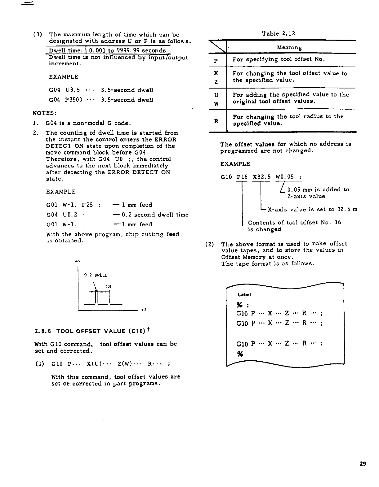
(3)
The
designated
Dwell
Dwell
increment.
EXAMPLE:
G04
G04
NOTES:
G04
1.
2.
The
the
DETECT
move
Therefore,
advances
after
state
maximum
time:
time
U3.
P3500
is
non-modal
a
counting
instant
ON
command
detecting
.
5
to
with
is
•••
the
state
with
the
length
0.001
not
of
dwell
control
block
G04
next
the
of
address
9999.99
to
influenced
3.
5-second
3.
5-second
G
code.
time
enters
upon
before
U0
block
ERROR
time
which
U
or
seconds
by
dwell
dwell
is
started
the
completion
G04.
the
immediately
DETECT
is
P
input
control
can
as
follows.
/output
from
ERROR
of
the
ON
be
P
For
X
For
the
Z
For
U
original
W
For
R
specified
offset
The
programmed
EXAMPLE
G10
specifying
changing
specified
adding
changing
P16
Table
tool
values
are
X32.5
the
offset
value.
not
2.12
Meaning
tool
tool
the
value.
specified
tool
the
which
for
changed.
WO.
05
offset
offset
values.
radius
;
No.
value
no
value
to
to
the
address
to
the
is
EXAMPLE
GO
G04
G01
With
is
2.8.6
With
and
set
(1)
W-l.
1
U0.2
W-l.
the
obtained.
TOOL
G10
corrected.
G10
F25
;
;
above
•»\
0.2
OFFSET
command,
P...
;
program,
DWELL
tool
X(U)---
—
—
1
MM
VALUE
mm
1
0.2
1
mm
—
chip
(C10)
offset
Z(W)---
feed
second
feed
cutting
values
+
R---
dwell
can
feed
be
time
(2)
The
value
Offset
The
above
tapes,
Memory
tape
Label
%
G10
do
G10
%
*—
Contents
changed
is
format
and
format
;
P
—
•••
P
•"
P
z
X-axis
of
is
to
once.
at
is
•••
X
X
•••
X
0.05
Z-axis
value
tool
used
store
follows.
as
Z
Z
—
Z
is
mm
value
set
is
offset
R
No.
make
to
values
the
;
—
•••
;
R
•••
;
R
added
to
offset
16
to
32.5
in
m
With
set
this
or
command,
corrected
offset
tool
in
part
programs.
values
are
29
Page 40

2.8.7
CORNERING
(Cll,
C12)
X
(1)
Beveling
G
11
Gil
+x
(Gil)
X(U)--.
Z(W)---
X(U)---
END
POINTÿ
K-.-
Beveling
K-
w..
45'
Z
+
for
K--
K+
START
POINT
(E
)
F
•• •
X-axis
F(E)
U
X
2
(DIAMETER)
command
This
workpiece.
specified
of
Table
Meaning
2.
13
Beveling
•
•
Gil
1+
Z(W)...
END
POINT
removes
Addresses
simultaneously
each
address
for
Z-axis
F
•
•
•
I
45*
oSTART
(E)
the
sharp
and
X
in
is
.
.
.
POINT
Z
a
block.
shown
corner
cannot
below.
of
be
I-
T
Z
w
Beveling
the
following
K
|
I
The
command
format
(T)
D
K
I
L10
values
<
|U/2j
error.
GOO
Gil
(Gil)
7
D1A
-
d
n
(K
values.
exceeding
X30.
Z-20.
X80
«*x
20
Beveling
Beveling
and
I
(
.
,
ZO
18.
K-7.
I)
|<|
the
F30
;
Value
Direction
are
limited
W
|
above
;
value
within
causes
I
(2)
This
corner.
ified
is
formed
each
Rounding
G
Beveling
(Radius
Beveling
(G12)
X(U)---
12
Z(W)-
command
performs
Addresses
simultaneously
as
a
quarter-round.
address
is
•
shown
X
in
K---
•
I
Value
Value)
Direction
•
•
the
and
Z
a
block.
below.
(E)
F
rounding
cannot
The
Meaning
•
•
be
of
the
spec¬
corner
of
30
8-
T\«
50
DIA
Fig.
2.10
Page 41

Table
2.14
G
12
+X
K
Rounding
the
following
|K|
The
command
causes
X(U)---
END
POINT
i
<
format
Rounding
K-
o—
+Z
values
values.
|u/2|
exceeding
error.
K---
K+
«r
START
Rounding
Rounding
(K
and
for
X
F(E)
u
2
(DIAMETER)
POINT
I)
l|
|
the
axis
• •
•
X
value
direction
are
limited
<
|w|
above
value
within
Z(W)---
G12
END
POINT
Ik
-ur
Z
i
K
NOTES:
Gil
1.
They
the
2.
Gil
are
block,
Rounding
I
W
G12
and
remain
group
and
commanded
they
A
G12
constitute
Z
for
(E)
••
F
START
POINT
<
Rounding
are
modalGcodes
effective
are
commanded.
are
for
for
both
axis
one
.
.
•
value
direction
until
axis
axes
format
a
;
other
m
only.
in
error.
the
G
the
A
codes
If
they
same
group.
in
(I
©
GOO
12
G
(G
12)
X20.
Z-25.
,70
ZO
19.
X70
3
«
D1A
TV
2D
K-6
D1A
EXAMPLE
W-
G12
;
30
F
;
F20
In
3.
I
and
can
4.
5.
6.
7.
manded,
assured
Tool
tive
In
of
ing
G01
fy
G01
GDI
+x
25
«
U/
$
+z
fy
be
G01
•
X-
the
G10
nor
K
be
commanded.
.
radius
to
the
the
finish
the
special
or
Gil
code
identical
X(U)-..
Z(W)-..
code
rounding.
instead
used
X(U)---
Z(W)--.
•
•
or
G
block
correct
compensation
blocks
form
canned
G12
can
be
beveling.
can
be
•K•
12
can
However,
modes,
whichIand
in
If
tool
containing
commands
be
used
K-..
I--.
used
I
of
and
R...
R---
•
no
block
suchablock
movement
function'1'
Gil
G70
+,
cycle
commanded.
instead
blocks
F(E)
instead
in
this
K.
F(E)
of
of
••
•
•
Error
can
•
without
K
are
not
is
or
through
Gil
;
G12
case,
•
"050’'
0
is
com¬
be
effec¬
G12.
contain¬
speci¬
to
to
speci¬
R
must
G73
31
Page 42
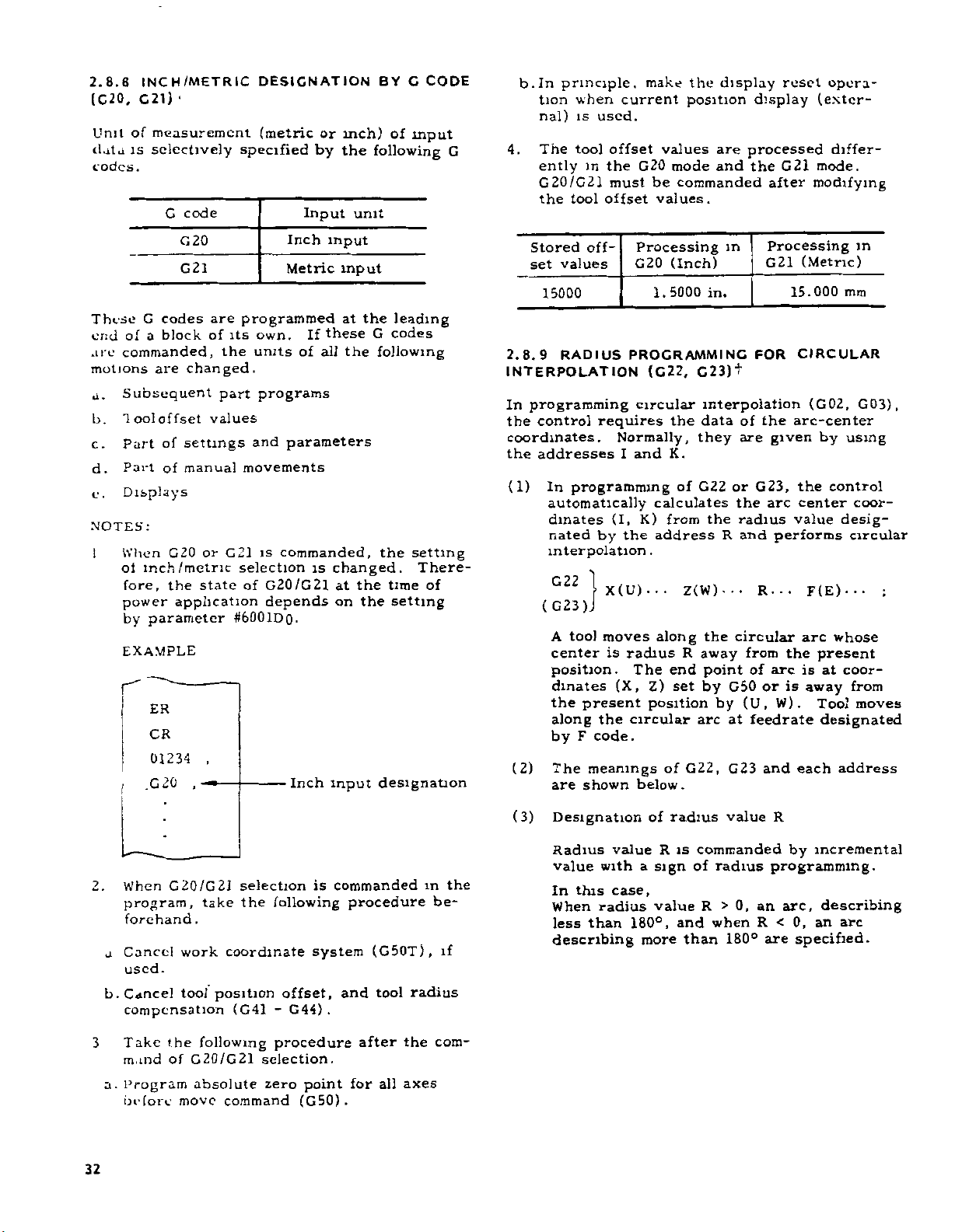
2.8.8
(C20,
Unit
data
codes.
INCH/METRIC
)
21
G
of
measurement
is
selectively
G
code
DESIGNATION
(metric
specified
Input
by
or
inch)
the
unit
BY
CODE
C
of
input
following
opera¬
make
the
b.In
principle,
current
when
tion
nal)
is
used.
The
G
4.
ently
G20/G21
the
tool
tool
in
offset
the
must
offset
G20
values
mode
be
values.
display
position
are
and
commanded
reset
display
processed
G21
the
after
(exter¬
differ¬
mode.
modifying
These
of
end
commanded,
are
motions
Subsequent
a.
"lool
b.
Part
c.
Part
d.
Displays
e.
NOTES:
When
1
ol
fore,
power
by
EXAMPLE
r
G20
G21
G
codes
block
a
changed.
are
offset
settings
of
manual
of
or
G20
inch/metric
the
state
application
parameter
ER
CR
01234
,
20
.G
-
are
of
the
part
values
G21
,
its
#6001DQ.
Inch
Metric
programmed
own.
of
units
programs
parameters
and
movements
commanded,
is
selection
of
G20/G21
depends
Inch
If
input
these
all
is
input
at
the
G
the
changed.
the
at
on
the
input
leading
codes
following
the
setting
There¬
of
time
setting
designation
Stored
set
off¬
values
15000
2.8.9
RADIUS
INTERPOLATION
In
programming
control
the
coordinates.
the
addresses
(1)
In
requires
programming
automatically
tool
(I,
by
X(U)---
moves
is
dinates
nated
interpolation
G22
(G23)
A
center
position.
dinates
the
present
the
F
code.
meanings
shown
(2)
(3)
along
by
The
are
Designation
Processing
(Inch)
G20
1.5000
PROGRAMMING
(C22,
circular
Normally,
and
I
K)
the
G23)t
the
they
K.
G22
of
calculates
from
address
interpolation
data
.
Z(W)---
end
set
of
radius
R
arc
G22,
the
away
point
by
radius
The
(X,
circular
along
Z)
position
below.
of
in.
the
by
in
of
are
or
the
radius
and
R
circular
from
G50
(U,
at
G23
value
Processing
G21
FOR
the
given
G23,
arc
performs
R...
the
arc
of
or
is
W).
feedrate
and
R
(Metric)
15.000
mm
CIRCULAR
(G02,
arc-center
by
the
control
center
value
F(E)
arc
desig¬
whose
present
is
coor¬
at
away
Tool
designated
address
each
in
G03)
using
coor¬
circular
••
from
moves
,
2
a
b.
3
a.
32
G20/G21
When
program,
forehand
Cancel
used
Cancel
compensation
Take
mand
Program
before
work
.
tool
the
of
move
take
.
coordinate
position
(G41
following
G20/G21
absolute
command
selection
the
following
-
procedure
selection.
zero
offset,
G44)
point
(G50).
commanded
is
procedure
system
and
.
for
(G50T),
tool
after
all
radius
the
axes
in
be¬
com¬
is
R
sign
value
commanded
of
radius
R
when
and
than
>0,
180°
an
R
are
this
with
radius
than
value
a
case,
180°,
more
Radius
value
the
In
When
less
if
describing
incremental
by
programming.
arc,
describing
0,
an
<
specified.
arc
Page 43
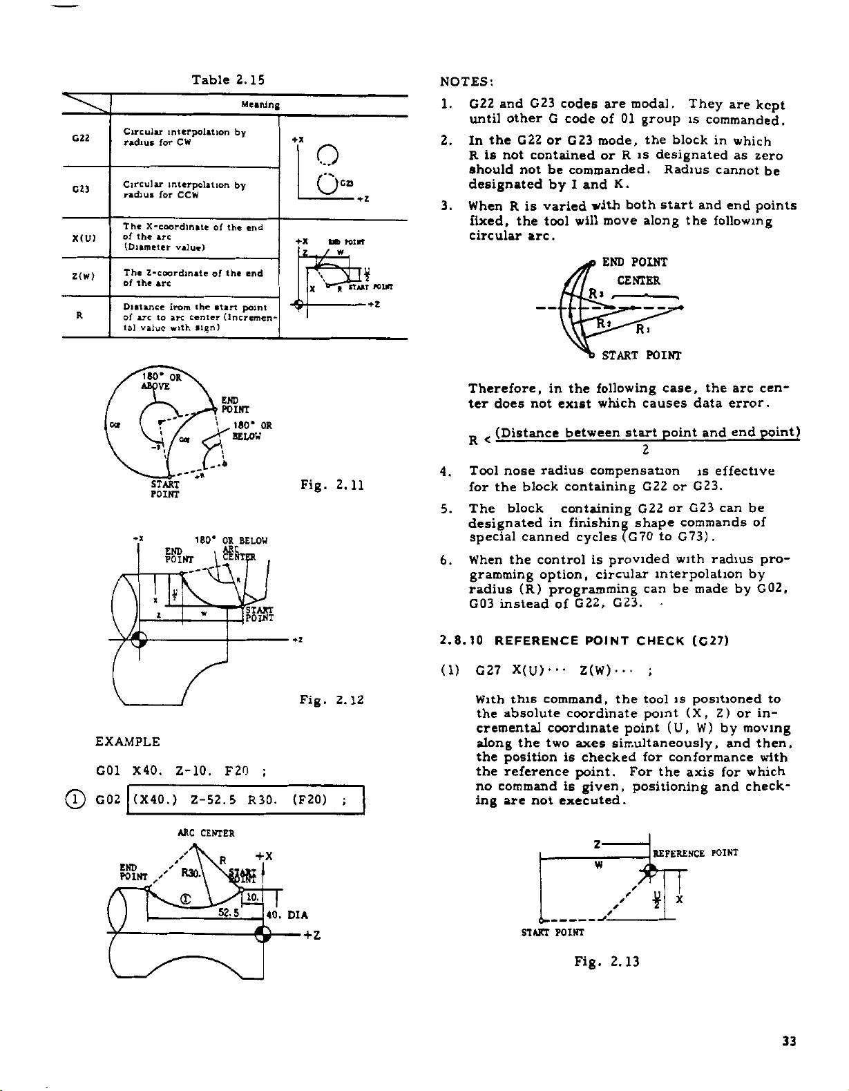
C22
C23
X(U)
Z(W)
R
Circular
radiu*
Circular
radius
The
X-coordinatc
of
the
(Diameter
The
Z-coordinate
of
the
Distance
of
arc
tal
value
interpolation
for
CW
interpolation
for
CCW
arc
value)
arc
from
arc
to
with
Table
the
center
sign)
of
the
of
the
start
(Incremen¬
2.15
Meaning
by
by
end
end
point
+x
+X
<)ÿ
o
O"
UD
X
POINT
rtAAT
FOUfT
NOTES:
G22
1.
until
In
2.
R
should
designated
When
3.
fixed,
circular
is
the
and
other
not
R
G23
G22
contained
not
is
varied
the
tool
arc.
codes
G
code
or
G23
be
commanded.
I
and
by
will
mode,
with
R*
are
of
01
R
or
K.
move
END
CENTER
t
modal.
group
the
is
both
along
POINT
i
R
They
is
block
designated
Radius
start
and
the
are
kept
commanded.
in
which
as
zero
cannot
end
points
following
be
0
180*
co
START
POINT
EXAMPLE
G01
X40.
(X40
G02
OR
VE
\/L
END
POINT
2
Z-10.
)
.
t
A
180*
w
Z-52.5
END
POINT
180*
BELOW
BELOW
OR
ARC
CENT
F20
OR
"START
POINT
;
R30.
Fig.
Fig.
(F20)
2.11
2.12
;
4.
5.
6.
2.8.10
(1)
Therefore,
ter
does
(Distance
<
R
nose
Tool
for
the
block
The
designated
special
the
When
gramming
radius
G03
instead
REFERENCE
X(U)---
G27
this
With
the
absolute
cremental
along
position
the
the
reference
no
command
are
ing
in
not
radius
block
in
canned
control
option,
(R)
programming
command,
coordinate
two
the
not
the
following
which
exist
between
compensation
containing
containing
finishing
cycles
is
circular
G22,
of
POINT
(W)
Z
coordinate
axes
checked
is
point.
is
given,
executed.
START
POINT
case,
causes
point
start
2
G22
or
G22
shape
(G70
to
provided
interpolation
can
G23.
CHECK
;
•••
tool
the
point
point
(U,
simultaneously,
for
For
the
positioning
the
error.
data
end
and
is
effective
or
G23.
G23
can
commands
G73).
radius
with
made
be
(C27)
is
positioned
Z)
(X,
W)
by
and
conformance
for
axis
and
arc
be
by
by
or
moving
which
check¬
cen¬
point)
of
pro¬
G02,
to
in¬
then,
with
END
POINT
ARC
CENTER
+x
R
R30.
/
''
<D
52.5
m
10.
&
40.
DIA
6--
START
w
—
—
POINT
Fig.
/
2.13
REFERENCE
£
¥
POINT
A
33
Page 44

2.8.10
(CONT'D)
(2)
REFERENCE
the
If
return-to-reference
tion
directions
continued
is
the
this
and
(Cycle
NOTES.
1.
The
machine
motion
the
reference
erence
Automatic
2.
If
G
mode,
set
displaced
tool
the
at
G27,
EXAMPLE
a.
Cancelling
ceding
C
b.
Cancelling
G27
3.
The
motion
return
G69
off).
2.8.11
POINT
AUTOMATIC
(C
position
the
is
reference
constitutes
the
automatic
start
reference
tool
point
27
commanded
is
offset
reference
cancel
T
27
U-.-
U-
mirror
commanded
position
mode
28)
is
reference
specified,
further.
point
the
lamp
point
to
which
under
return
point
return
Reference
tool
the
the
from
value.
the
tool
tool
G27.
00
W---
m
.
W.
image
error,
(Opposite
POINT
the
reference
lamp
point
the
even
ret
operation
goes
is
the
the
control
function.
Point
in
returns
reference
Positioning
point.
offset
offset
;
;
the
block
.
.
T
function
by
G27.
tool
RETURN
CHECK
lights.
in
automatic
the
If
along
urn
-position-error
off.)
an
fixed
tool
G28
or
Return.
the
tool
to
Before
mode.
in
the
containing
IHOO
is
To
command
post
TO
(G27)
point,
The
axial
the
all
operation
position
one
axis,
is
interrupted.
on
point
can
return
of
the
automatic
automatic
6.2.1
See
position
the
position
by
point
cannot
be
commanding
block
pre¬
G27.
;
effective
G27
the
m
image
avoid
mirror
REFERENCE
the
posi¬
is
the
with
the
not
,
the
by
ref¬
off¬
made
the
The
which
(2)
When
pleted,
returned
to
automatic
(3)
The
motions
application,
reference
low-speed
RAPID
SPEED
Thereafter,
POINT
command
the
+
tool
the
series
TRAVERSE
SPEED
motion
RAFIS
X
START
POINT
the
REDUCTION
INTERIM
POSITIONING
14
Fig.
not
does
instruction
return
Reference
axis
lights.
reference
operation
RETURN
of
are
as
the
point
mode
APPROACH
UNIT
Fig.
RETURN
the
rapid
is
in
GOO.
of
TRAVERSE
POSITIONING
\
¥
2.14
move
omitted.
is
reference
to
Point
When
in
point
is
resumed.
follows.
return
as
are
shown
as
SPEED
APPROACH
SV
REFERENCE
POINT
2.15
TO
traverse
POINT
V
REFERENCE
•
POINT
\
'
RETURN
TO
X
J
the
along
motion
Return
both
TO
With
motions
shown
1
DISTANCE
REFERENCE
lamp
the
axes,
REFERENCE
initial
below
below.
SPEED
SEQUENCE
SPEED
as
REFERENCE
+z
for
axis
com¬
is
for
returns
tool
the
power
to
the
the
in
BY
SET
1
PARAMETER
2
J
under
the
34
(1)
X(U)
G28
this
to
passing
words,
command,
the
absolute
With
back
after
other
manded
incremental
or
simultaneously
automatically
reference
the
by
The
specified
known
or
as
"INTERIM
• •
z
(W)
reference
through
tool
the
coordinate
position
along
returns
point
point
’’INTERIM
POINT.”
;
•
•
tool
an
(U,
the
return
Z)
interim
two
can
automatically
position
W)
axes,
reference
function.
(U,
or
the
point
positions
the
to
(X,
POSITIONING
be
to
by
brought
point.
the
(X,
moving
and
W)
POINT,"
com¬
then
point
is
In
Z)
(4)
However,
by
fied
same
low
obtained
Fig.
when
parameter
motion
.
2,
16
traverse
low
#6010D5
speed
as
SPEED
set
in
speed
to
the
SEQUENCE
is
1,
the
1st
time
speci¬
is
Page 45

NOTES:
For
1.
the
in
turn
2.
The
ENCE
shown
be
3.
Before
the
a.
b.
4.
When
offset
offset
celled.
2.8.12
(1)
With
a
it
zero
REFERENCE
parameter
low
traverse
2.8.11.2,
Fig.
to
Reference
starting
POINT
in
started
RETURN
DIRECTION
REFERENCE
m
writing
tool
position
Cancelling
G28
Cancelling
G28
G28
or
or
RETURN
this
specified
been
has
point
setting
speed
refer
point
motion
Fig.
2.8.11.4.
any
from
fgiBSoN
G28
offset
in
the
T
is
written
radius
FROM
function,
point
once
by
ZERO
Z-.
in
Z...
the
the
returned
X---
X...
tool
compensation
and
other
return
to
6.2.1
Point.
for
RETURN
must
be
Fig.
position.
*
r
RETURN
POSITION
the
in
as
program,
shown
preceding
;
block
TDD00
with
the
compensation
is
automatically
REFERENCE
the
tool
via
the
interim
to
AUTOMATIC
COMMAND
details
motion
in
the
Manual
TO
shown
REFER¬
area
2.8.11.3
AXIS
.DECELERATION
SWITCH
LIMIT
UNABLE
cancel
.
below
block
containg
tool
is
the
G28
position
on,
POINT
positioned
point,
reference
RETURN
(G28).
the
can¬
(C29)
of
Re¬
can
after
to
TO
(2)
in
ordinate
(3)
Motions
taneously
erse
the
(4)
Where
the
struction
Coordinates
these
NOTES:
1.
Commanding
G28
an
2.
In
gramming
med
point
point
G29is
When
tance
between
programming.
tal
instructions
useful
to
reference
However,
.
direction
G28
point
EXAMPLE
two
28
20
N
G
G28
N25
N26
G29
GOO
GOO
after
error
principle,
while
B
will
B1.
used,
points
return
system
zero.
"*•
B
C
"059."
and
along
for
is
programmed
B
created
effective
is
(absolute
of
interim
blocks.
X10.
X30.
X-40.
X30.
X-40.
G29
turning
cancel
G28orG29.
offset
offset,
be
consideration
B
Especially
used
are
tool
the
after
B
two
the
tool
the
which
by
for
input)
Z20.
Z-50.
Z20.
Z-50.
without
the
on
tool
effective,
is
and
,
this
to
returning
+
are
D
axes
will
instruction
several
latest
the
the
point
;
;
the
control
offset
If
they
and
the
C
is
when
function
the
original
to
made
in
rapid
not
motion
is
equivalent
X
(10.
-(30.
execution
before
are
the
tool
on
the
dis¬
unnecessary
incremen¬
is
co¬
the
simul¬
trav¬
move
in
is
omitted.
times,
G28
in¬
by
G29.
z
20.)
20.)
of
constitutes
pro¬
program¬
interim
will
pass
to
G28
G29
DO'*
X...
Point
X-*
Point
4s
j
/
6
A
..
Z
B
Z...
D
(REFERENCE
c
ZERO
i
i
B
t
-*ÿ
-*•
B
A
Point
(reference
Point
POINT)
MIEIENCE
INTERIM
Fig.
POINT
2.17
C
ZERO
zero
-ÿ
B
C
point)
D
D'
--'A<
/
/
A'
(REFERENCE
C
POINT)
ZERO
//
/
/
/
/
/
/
t
(1
t>#
(INTERIM
OFFSET
DISTANCE
POINT)
35
Page 46

2.8.12
(C29)
NOTES:
Commanding
3.
PENSATION
CYCLES
stitutes
EXAMPLE
N
N51
N52
N53
O
2.8.13
(1)
START
POINT
RETURN
(CONT'D)
50
T0300
G28
T0400
G29
/
4-
A
20
2ND
30
G
With
interim
an
W)
in
then,
and
tool
The
which
o—
(G70
an
error.
U80.
U-80.
B
K
j
/
REFERENCE
X(U)
command,
this
axial
two
moves
does
no
coordinate
Z
W
/
INTERIM
POINT
FROM
in
G29
mode
-
G76,
.
W20.
.
W40.
y-
*
N.
V-
2(w)
positioning
directions
not
S
U/2
/
/
REFERENCE
the
TOOL
(G40
-
G44)
G90,
;
;
+
POINT
,
•
•
tool
the
point
the
along
position
2nd
to
move
''*"01
X
POINT
RADIUS
or
in
G94)
and
G92
(REFERENCE
c
X
ZERO
POINT)
RETURN
moves
first
Z)
(X,
or
simultaneously,
reference
the
axis
is
specified.
2ND
REFERENCE
POINT
COM¬
CANNED
con¬
(C30)i
to
(U,
point.
for
EXAMPLE
C
20
NOTES:
Before
1.
tion
TO
2.
For
motion,there
ing
from
3.
The
Automatic
to
4.
When
moves
to
the
specified
2.8.14
(1)
G
With
polation
lation
tool
immediately,
when
(2)
The
varies
block.
a.
W
U-40.
30
INTERIlTfoiNT
TO
2ND
REFERENCE
POINT
30
commanding
the
2nd
control,
REFERENCE
of
REFERENCE
the
is
is
impossible
any
position
same
notes
Return
G30
command.
G29
is
commanded
the
interim
point
G30.
by
FUNCTION
•
•
command,
executed.
is
movement
specified
-
the
interim
31
via
position
SKIP
X(U)
this
interrupts
and
motion
When
mental
The
tool
with
interpolation
the
a
the
the
skip
with
next
values:
moves
next
signal
after
the
.
2ND
1’OINT
&
7
PARAMETER
G30,
G28
POINT
no
area
,
and
the
3.
and
4.
to
Reference
after
point
is
renewed
(
C
Z(W)
the
instruction
block
incrementally
block
••
a
special
under
interpolation
proceeds
received.
is
the
receipt
is
from
is
interrupted.
•
During
REFERENCE
0
1ST
,
POINT
\
#6613
the
after
MANUAL
or
be
must
POINT
from
where
can
tool
(5)
of
G30,
specified
G29.
by
only
)
3
1
(F(E)
••
linear
the
instruction,
this
the
to
of
of
programmed
in
the
point
FAKAMV
#601
2
REFERENCE
energiza¬
RETURN
executed.
RETURN
return¬
be
2.8.11
for
apply
Point
the
by
However,
the
in
•)
:
inter¬
interpo¬
motion
next
a
skip
next
the
in
accordance
where
K
IF
return
tool
G30
axis
block,
signal
incre¬
the
36
(2)
2nd
The
advance
reference
1st
parameters
reference
terms
in
4*6612
Fig.
point
2.18
point
of
the
commanded
#6613.
and
is
specified
distance
by
from
G28,
in
the
by
Page 47

EXAMPLE
G31
G01
X
When
b.
lute
The
position
at
ceived,
EXAMPLE
G31
G01
the
W120.
U100.
z
the
values
tool
position
if
Z400.
X100.
ACTUAL
MOTION
next
only
moves
in
the
axis
X
;
;
120.
block
to
specified
where
is
;
,
ACTUAL
MOTION
SKIP
SIGNAL
for
the
not
O
z
Q
COMMANQÿJ
7
is
one
---
ON
programmed
axis:
specified
axis.
the
skip
specified.
COMMANDÿ!
400.
r
I
l
4
in
coordinate
remains
It
signal
r
i
I
is
100
50.
abso¬
re¬
D1A
(3)
(4)
a.
b.
(5)
NOTES:
When
1.
gram
cally
during
2.
Before
G40
SATION.
alarm
a
is
31
G
When
no
execution
tool
stops
"087"
is
The
feedrate
in
set
the
specified
Designation
normal
Presetting
When
values
as
programs,
skip
a
at
parameter
#6568
#6569
These
in
data
user
parameter
is
advanced
even
the
programming
cancelling
for
"024.
non-modal
skip
signal
the
of
at
the
displayed.
for
following
parameter
by
by
of
feedrates
signal
that
data.
for
storing
for
storing
can
macros.
when
execution
Failure
"
G
is
block
of
end
blocks
two
the
in
F
is
moment
X
Z
be
used
#6004Do
the
to
no
skip
of
G31,
TOOL
do
to
code.
received
containing
the
containing
methods,
#6019D4.
same
parameter
by
received,
are
automatically
coordinate
coordinate
system
as
set
is
next
signal
block
the
be
RADIUS
this
block,
way
to
block
is
sure
initiates
during
G31,
and
G31
selectively
as
with
#6323.
the
coordinate
value
value
variables
1,
the
automati¬
received
G31.
of
to
program
COMPEN¬
the
the
alarm
are
stored
pro¬
When
c.
lute
The
from
received.
EXAMPLE
G31
G01
the
values
tool
the
W100.
X300.
next
along
moves
point
block
to
at
:
Z200.
SKIP
SIGNAL
two
the
which
;
ON
is
programmed
axes:
commanded
a
skip
200
2
7
SKIP
SICNAL
signal
\
100
ON
in
position
\
300
\
\
3
abso¬
is
DIA
2.8.15
THREAD
This
function
taper
ding.
(1)
threads,
G32
With
to
coordinates
mental
nated
(2)
The
E
THREAD
CUTTINC
X(U)--.
this
the
point
coordinate
by
range
codes
CUTTINC,
is
for
scrolls
command,
(X,
or
or
F
of
is
as
(C32)
cutting
and
Z(W)-..
Z)
(U,
values,
E
code.
leads
follows.
CONTINUOUS
straight
for
continuous
F(E)
the
tool
specified
W)
specified
to
be
specified
threads,
thread-
•
•
•
.
cuts
threads
in
absolute
incre¬
in
a
at
lead
desig¬
by
up
and
F
37
Page 48

2.8.15
THREAD
THREAD
CUTTINC
CUTTING,
32)
(C
COUTINUOUS
(CONT'D)
Feedrates
follow
S
are
limited
.
s
spindle-speed
.is
Metric
Output
Inch
Output
(3)
The
codes
Limitation
\
+
I
F
E
Metric
Input
Inch
Input
Metric
Input
Inch
Input
code
code
(x,z)
J
•
T
is
is
direction
shown
is
of
Taper
Table
Format
32
F
E34
24
F
E26
32
F
E34
F24
E26
normal
for
for
precise
of
Direction
a
a
2.16
Programmable
for
Thread
F0.01
E0.
F0.
E0.
F0.01-F1270.00
E0.
F0.
E0.
lead
below.
Angle
45°
i
45°
>
0001
0001
000004
0003
001
000010
thread
thread
specified
Lead
of
Direction
Lead
of
Lead
of
-
Z-axis
X-axis
F500.
E500.
-
F19.6850
-
-
-
E1270.
-
F50.0000
-
cutting.
cutting.
in
in
00
E19.
F50.
by
the
the
Range
Cutting
0000
685000
0000mm
000000
and
F
of
Lead
direction
direction
mm
mm
in.
in
mm
in
in
of
format
L
6
i
6
2
-
=
F(E)
F(E)
X-axis
Table
G
G32
G
G
G32
G
5.0
=
5.0
=
3.0
1.0
;
N.
x
threadcutting
of
2.17
Command
Z(W)
32
Z(W)--X(U)-..
32
X(U)
32
X(U)
32
X
Thread
mm
mm
mm
mm
S
S
speed
(U)
Metric
Inch
The
half
(4)
output
output
upper
the
above.
Command
.
below
limit
Type
GOO
Normal
Precise
Normal
Precise
Normal
Frecise
Straight
lead
depth
U-42.
Straight
Thread
T
aper
Thread
Scroll
Thread
EXAMPLE:
E
Thread
Cutting
i
•
•••
•••
•
,
24
000
2,
400
component
format
.
F.
E-
2(W)-
Z(W)
•••
F
.
E.
•
nim/min
m
is
.
••
•
F-
••
F-
.
/mm
shown
•
•
is
;
(
!
18
,
.
©
kVvVAAAW
60
6
-iu
I
m
20
+z
42.
44.
68.
F5.0
;
,
;
;
1
i
i
I
1
Oi
-
J
+x
POINT
w
L
V
2U\
(U*d)
t
U/2
X/2
\
START
POINT
r
t
i
END
1
lfÿri
Z
\
I
o'
Fig.
I
2.19
©
GOO
G32
GOO
+x
U
W
U-44.
W-68.
U
W-68.
G32
Page 49

EXAMPLE:
Thread
Cutting
GOO
G32
GOO
G32
GOO
(5)
Continuous
(D
G
(G32)
(D
(G
(D
32
32)
Taper
lead
depth
X13.
X38.
X60.
W35.
X-ll.
X36.
X60.
\
+
60
1
(
X
X(U)
X(U)---
l<o
U
L
6
i
62=
DIA
thread
)
••
Thread
4.0
=
3.0
=
2.0
1.0
=
;
W-35.
;
W-35.
;
DIA"
•
•
•
•
r
1
<l<
(
Z
Z(W)
Z(W
mm
mm
mm
mm
F4.0
;
I
cutting
W)
)••ÿ
• •
®
*1
•
©
3
J1
9-
V
Xv7
)
(
b
;
V
1
1
i®
1
I
NOTES:
Allowances
1.
cutting
starting
Since
blocks
tinuous
thread
the
thread
boundary
X
-
the
is
thread
lead
because
and
time
stop
approximately
cutting
specification
becomes
of
blocks.
and
<5
1
lead
end
r
1
M
(J
,15
F(E)
•
•
•
•
•
-P
DIA
---
2.
3.
4.
&
If
spindle
cutting,
servo
Threading
G32.
commanded
The
ing
lag.
If
following
thread
speed
the
leads
up
for
necessary,
.
operation
cutting
Worm
between
6
2
points.
AAAAAAAAAAA/
not
is
become
thread
G92
including
Screw
zero,
is
irregular
are
error
constant
is
(or
is
thread
smooth,
possible
is
changed
near
required
occurs
y
1
i
t
,!
I
during
incorrect
not
effective
G76~)
disregarded
G32
cutting
the
for
near
due
should
con¬
If
midway,
thread
the
thread
to
at
dur¬
the
be
This
command
i
executes
©
)
(
a
Pipe
thread
(D
Joint
cutting.
n
1
5.
6.
•
Feedrate
•
Feed
The
G98
in
Dry
In
rate.
G32
Override
Hold
command
mode.
Run
Operation
mode,
should
the
Regarded
not
tool
be
moves
100"
as
commanded
feed¬
Jog
at
39
Page 50

IS
2.
8.
THREAD
(6)
Allowance
and
6
1
following
THREAD
CUTTINC
I
I
jare
6
equation.
CUTTINC,
for
lead
1
obtained
)
(
G
32
(CONT'D)
errorf
IAAAAAA/
2.20
Fig.
approximately
CONTINUOUS
62)
6
i,
from
the
after
point
cut
is
position
the
With
cutting
by
by
starting
the
the
starting
of
multi-start
a
thread
starting
the
spindle
pulse
by
point
the
cutting
position
thread
controlling
which
LEAD
pulse,
is
by
cutting
another
feed
displaced
a
preset
at
function,
the
an
angle.
starting
thread
angular
from
\
i
6
6
J
J
6
6
a
(lnT-»
EXAMPLE
Lead
Spindle
Thread
1
6
Equation
L
>
60
1/50
2
of
L.S
>
60.
-
S
K
1/100
91
3.61
thread
speed
cutting
(
K
3.0
60
Table
In
500
x
*K
L(ram)
S(rpm)
(-)
a
In
1/150
4.01
L
=
S
=
a
=
1
-
—
a
—
2.18
K:
3.0
500
1/100
1)
x
Meanings
.
Lead
Spindle
Constant
(Normal
30)
Accuracy
thread
Natural
(log
1/200
29
4
mm
rpm
3.61=
AL
L
1/250
4.52
of
e)
3.0
thread
speed
value:
of
Lead
error
logarithm
1/300
4.70
mm
(1)
G32
With
starting
displaced
to
by
specified
(2)
The
multi-start
as
Least
Programmable
When
The
only
(3)
Number
In
the
the
X(U)-..
command,
this
at
from
starting
the
B,
X(U)
to
by
data
specified
follows.
input
decimal
code
B
the
in
of
starts
principle,
workpiece
circumference
Two-start
Fig.
Z(W)..
an
angular
the
position
pulse
Z{W)
or
F
or
E
by
thread
cutting
increment:
range:
input
point
non-modal,
is
programmed
and
the
thread
circumference
into
Thread
2.21
the
by
code.
B
F(E)
•
cutsu
tool
position
corresponding
an
angle
point,
address
function
0.001
0
S
5
B
used,
is
andiseffective
block.
code
starting
should
equal
portions.
•
•
which
a
at
in
B
deg.
360.000
•
B
thread
is
specified
lead
the
is
Bl.=ldeg.
points
divide
on
2.8.16
With
two
without
cutting,
start
by
control
same
HO
6
2
MULTI-START
this
or
more
shifting
the
point
a
pulse
the
position
L-S
>
60
function,
threads
tool
pulse
generator
starting
around
K
the
feed
3.0
r
THREAD
multi-start
per
starting
is
(1
pulse
installed
point
the
500
X
K
60-
can
lead
point.
started
/revolution)
of
thread
workpiece
=
CUTTINC
threads
be
in
phase
on
the
0.
ram
83
(C32)
containing
machined
thread
In
with
generated
spindle
always
to
the
at
circumference.
1ST
2ND
3RD
4TH
4-START
STARTING
THREAD
THREAD
THREAD
THREAD
THREAD
POINT
i
NO
COMMAND
190
BIBO
1270
3-START
THREAD
2
-START
STARTING
+
1ST
THREAD:
2ND
THREAD
a
POINT
IK"
NO
CONtAND
BIlO
B
1ST
2ND
3RD
Fig.
STARTING
THREAD
THREAD
THREAD
2.22
THREAD
POINT
NO
B
COfftAND
1120
1240
Page 51

NOTES:
Since
1.
(4096
dle
angular
to
command,
360°/4096
From
an
2.
The
can
directions
When
3.
succession,
trolled
mand
required
When
4.
outside
alarm
the
pulses/rev.)
pulse
the
starting
the
error
angular
specified
be
cutting
from
in
B
command
the
11
065"
angular
generator
position
the
pulses
position
to
up
position
by
if
the
the
first
from
permissible
is
position
of
point
least
0.
=
commanded
±1
pulse
in
BO
B
-
many
angular
the
starting
block,
2nd
the
is
displayed.
detection
generated
is
used
the
spindle
as
controlled
detectable
0879°/pulse.
may
from
the
both
forward
360,
commands.
multi-start
position
pulse
no
block
to
made
range
from
to
define
with
increment
by
occur.
starting
threads
by
B
command
on.
specify
(0
the
by
codes,
B
and
is
a
angles
360.000),
-
pulses
spin¬
the
respect
the
pulse
reverse
in
con¬
com¬
B
is
lead
or
by
SCREW
Thread
for
CUTTING
•
F(E)
screws
decrease
address
Cutting
variable
•
are
of
K.
2.8.17
(1)
B
is
(2)
VARIABLE
X(U)-..
G34
this
With
controlled
per
lead
2.23
Fig.
range
The
screws
lead
revolution
LEAD
Z(W)--.
command,
with
VARIABLE
Variable
of
K
as
is
THREAD
K--
variable
the
increase
specified
LEAD
Lead
programmable
follows.
EXAMPLE:
GOO
U--
•
• •
•
••
-
•
W-
U---
W--.
U--
W---
u
;
W'
•
••
G32
GOO
W-
u-
G
32
GOO
32
G
GOO
W-
•
U
32
G
Two-start
;
•
•
F
:
;
B180.
,
B180.
;
Thread
>
Threading
Least
of
part
@
a.
The
b.
The
in
c.
Feedrate
d.
Lead
input
0.
0001
(Metric
Programmable
highest
programmable
(metric)
lead
4194.
419.4303
total
is
303
or
displacement
within
mm
in.
change
variation
(metric
must
output)
value
increment:
mm/rev.
Input)
range:
feedrate
feedrate
in
50
(metric
(inch
not
or
should
0.000001
is
within
range
/rev.
the
(inch))
resulting
following
output)
output)
corresponding
exceed
540
inimm
not
be
minus
(Inch
5,400
the
(500
.
(inch
in/rev.
Input)
from
lead
to
mm
value.
mm
maximum
/rev
changes
/min
output).
NOTES:
are
When
1.
ous
interrupted
2.
If
alarm
When
3.
Run
specified
command,
is
When
4.
1,
mm/rev
Commanding
5.
alarm
variable
block
K
commands
n060"
G34
mode,
to
set
parameter
least
"060."
programs
at
will
command
the
the
by
parameter
if
1.
increment
or
0.0001
address
lead
block
exceed
be
tool
manual
10IN”
"
threads
,
command
junctions.
the
displayed.
is
executed
moves
SCRDRN
K
for
in./rev.
in
B
continuous
(#6006Ds)
commands
cut
pulses
permissible
in
at
only
G34
block
by
the
the
feedrate
(#6019
is
is
causes
continu¬
are
range,
Dry
speed
BIT5)
to
set
0.001
41
Page 52

2.8.17
(CONT'D)
(3)
Confirmation
variable
K
a.
conditions
(i)
(H)
(m)
(iv)
b.
The
above
F:
K
W
s.
N
VARIABLE
lead
command
.
Feedrate
programmable
mm/rev
500
(inch
rev
Feedrate
value.
Accumulated
variation
lead
(metric
mm
output)
Feedrate
variation
(metric
control
•
.
using
Fixed
rev)
Variable
in/rev)
Distance
Z-axis
on
facing
For
U
as
Spindle
Spindle
start
.
on
LEAD
calculation
thread
restricted
is
end
at
(metric
output)
end
at
output)
change
must
output)
checks
the
lead
lead
between
(mm
X-axis.
speed
speed
end
and
THREAD
cutting.
point
range.
point
of
value
must
corresponding
not
or
the
following
command
command
or
screw,
(rev/min)
for
points
for
the
in
must
output)
must
movement
not
exceed
or
419.4303
exceed
540
m/mm
restriction
equation.
(mm
start
inch).
distance
movement
(rev)
CUTTING
command
K
following
not
or
not
5,400
(inch
/rev
(mra/rev
end
and
is
exceed
in
50
be
minus
due
4194.303
(inch
in
to
lead
mm/mm
output
described
or
in/
or
points
specified
between
2.8.18
of
This
tool
the
switch
and
switch,
late
(1)
to
(2)
TOOL
function
offset
tool
(contact
when
the
G98
35
G
or
G35
With
in
a
signal
switch
set
value
tool
in
porated,
The
New
"
Absolute
at
touched
(Xj
Example
shown
value
is
replaced.
the
a
signal
new
X(U)---
Z(W)---
the
the
value
replaces
returns
which
new
offset
which
SET
for
is
to
detector)
tool
is
tool
offset
above
directions
for
tool
is
input
for
to
the
by
moving
tool
=
coordinate'
new
switch
or
Zj)
of
G35
.
below
ERROR
automatically
suit
comes
input
(F---)
(F.
instructions,
to
the
the
the
position
offset
COMPENSATION
to
the
this
For
installed
is
into
to
the
value.
;
••)
;
specified
contact
control,
the
tool
is
stored
start
correction
in
rapid
value
tool
operation
rewriting
tool,
new
purpose,
contact
control
Feed
-
X-Axis
Compensation
Z-Axis
Compensation
the
X(U)
by
with
the
the
calculated.
value.
of
point
traverse.
as
is
"Absolute
which
at
tool
(Xp
X-axis
for
when
a
touch
externally.
with
the
to
calcu¬
/Minute
tool
or
touch
tool-off¬
This
Then,
the
is
incor¬
follows.
coordmat
reference
touched
or
Zp)
is
(C35)
the
moves
Z(W),
the
block,
switcl
42
(i)
(n)
(m)
(iv)
(v)
alarm
N
•
j-
+
j
K-N
for
KN
for
2
)
for
£
for
mm
output)
Equation
+
F
Equation
(F
+
Equation
4-KN2
1
Equation
4194.303
(inch
in
Commanding
"060."
-(F
+
2
4194.
£
address
£-)
*
limit
;
500.000
50.
limit
KW
limit
303
419,4303
limit
5,400
(metric
in
0000
m
>
in
in
mm
(F
+
y
a.
a.
0
a.
mm
a.
/mm
output)
B
(l)
mm
in
(ii)
(lii)
or
in
(iv)
in
+
K
/rev
/rev
or
G34
2
-§-)
or
540
or
block
K
2-
in/min
419.4303
causes
W
\
+
The
the
touch
#6624
U/
2
x
coordinate
reference
switch
(Xp)
CONTACT
7
HAX
MEASURABLE
Fig.
tool
must
and
%
/
value
makes
be
#6625
POSITION
2.24
(Xp
set
(Zp)
(XT-XP)-
IAT
7
XT
or
contact
by
in
NEW
API
0FFSET
xr
at
Zp)
which
with
parameters
advance.
to°1'
the
Page 53
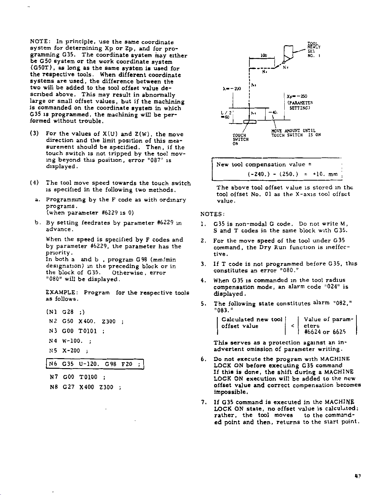
NOTE:
system
gramming
be
G50
(G50T),
the
respective
systems
two
will
scribed
or
large
is
commanded
G35
is
formed
(3)
For
direction
surement
touch
ing
displayed
(4)
The
is
a.
Programming
programs
(when
b.
By
advance
When
by
priority
In
designation)
the
"080"
EXAMPLE:
as
(N
N
N3
N
N5
N
N7
N8
In
principle,
for
determining
G35.
system
as
or
long
tools.
used,
are
be
added
above.
small
offset
on
programmed,
without
the
trouble.
values
and
should
switch
beyond
.
move
tool
specified
.
parameter
setting
.
the
speed
parameter
.
both
a
block
of
will
be
follows.
;)
28
1
G
2
G50
X400.
GOO
T0101
4
W-100.
X-200
6
G35
U-120.
GOO
T0100
G27
X400
The
coordinate
the
as
the
the
to
the
This
values,
the
coordinate
the
of
the
not
is
this
speed
in
the
by
feedrates
is
#6229,
b
and
in
the
G35.
displayed.
Program
;
use
the
Xp
work
same
When
difference
tool
may
result
machining
X(U)
limit
be
specified.
tripped
position,
towards
following
F
the
#6229
by
specified
the
,
program
preceding
Otherwise,
Z300
G98
:
Z300
same
or
Zp,
system
coordinate
system
different
between
offset
in
but
if
system
Z(W),
and
position
by
error
two
as
code
0)
is
parameter
by
parameter
G98
for
the
;
;
F20
;
coordinate
and
for
may
system
is
used
coordinate
value
abnormally
the
machining
in
will
be
the
of
this
Then,
the
tool
"0871'
the
touch
methods.
with
ordinary
#6229
codes
F
has
(mm/min
block
error
respective
pro¬
the
de¬
which
per¬
move
mea¬
if
is
or
either
for
the
mov¬
switch
in
and
the
in
tools
New
The
tool
value
NOTES:
1.
G35
S
2.
For
command,
tive
3.
If
constitutes
When
4.
compensation
displayed
5.
The
"083."
This
advertent
6.
Do
LOCK
If
LOCK
offset
impossible.
If
7.
LOCK
rather,
ed
X--200
1/
2'
“60
/
TOUCH
SWITCH
ON
tool
compensation
(-240.)
above
offset
.
is
non-modal
andTcodes
move
the
the
.
T
Calculated
offset
not
this
G35
point
is
code
G35
is
.
following
value
serves
omission
execute
ON
before
done,
is
ON
execution
value
command
state,
ON
the
and
an
100
N<
N
*
N«
40.
—
\
\
MOVE
TOUCH
-
offset
tool
01
No.
not
commanded
as
and
as
G
the
in
speed
Dry
Run
programmed
error
mode,
state
new
tool
protection
a
the
executing
the
correct
is
executed
no
moves
tool
then,
1
f
L-"”
--
y
Xp”
{PARAMETER
SETTING)
AMOUNT
SWITCH
value
(250.)
value
the
code.
same
of
the
function
"080."
in
alarm
an
constitutes
<
parameter
of
program
shift
during
will
be
compensation
offset
returns
—250
UNTIL
=
is
X-axis
Do
block
tool
the
Value
eters
#6624
against
with
G35
added
in
value
to
to
TOOL
NEWLY
SE1
.
N0
IS
ON
=
+10.
stored
not
under
is
before
tool
code
alarm
writing.
command
the
is
the
the
I
mm
i
m
offset
tool
M
write
G35.
with
G35
ineffec¬
G35,
radius
"024"
of
or
MACHINE
MACHINE
a
to
is
"082,"
param¬
6625
in¬
an
the
becomes
MACHINE
calculated;
command-
point.
start
the
,
this
new
U?
Page 54

2.8.19
This
into
tool
operation
secure
hibited
STORED
function
the
mode
safer
areas
STROKE
for
is
prohibited
and
operation.
be
can
LIMIT
preventing
area,
manual
Three
set
up
the
in
both
operation
types
as
shown
(C36
C39)“
-
entry
automatic
mode,
of
below.
of
pro¬
to
the
G
36
The
single
•
U
•
L
Point
coordinate
area
check
code
W-
T
block
••
j
C
I.
t
Point
coordinate
function
G37
•
••
K
T
j
D
turned
is
;.
off
by
a
(1)
a.
b.
c
(2)
a.
b.
2ND
(BY
B
Setting
Set
B
The
B
This
.
programs
Setting
Set
D
Selectively
side
parameter
PROHIBITED
C36)
INSIDE
OUTSIDE
PROHIBITION
D
+
side
parameter.
by
area
is
prohibited.
area
side
the
by
of
+
Z
1st
outside
.
2nd
the
setting
AREA
OR
prohibited
boundary
can
not
prohibited
boundary
designate
area
#6007Dq.
1ST
(BY
OUTSIDE
C
F
3RD
AREA
Fig.
the
be
function.
between
PROHIBITED
PARAMETER)
INSIDE
SIDE
i
PROHIBITED
(BY
2.25
area
and
A
range
specified
area
C
and
the
inside
points
AREA
PROHIBITION
OUT¬
OR
PROHIBITION
C38)
boundary
side
-
between
part
by
boundary
side
-
or
C
and
E
points
the
out¬
E
by
(3)
Setting
Set
a.
boundary
A
Selectively
b.
side
parameter
c.
In
function,
used
on
38
G
The
single
A
1st
prohibited
area
2nd
prohibited
area
3rd
prohibited
area
(4)
Table
Coordinate
3rd
up
side
point
of
the
#6007Di-
#6007DI
0
1
addition
the
the
to
set
area
•
•
U-
Point
coordinate
area
check
code
2.19
Setting
Point
Point
Point
Point
Point
Point
prohibited
boundary
F
designate
area
between
to
the
following
a
prohibited
check
•
W-
•I-••
E
function
block
Patameters
Prohibited
X
A
B
C
D
E
F
system
the
by
the
Inside
Outside
method
function
L
Point
coordinate
G39
axis
#6600
#6606
#6500
#6502
#6504
#6506
for
area
point
setting
inside
points
Meaning
prohibition
by
instruction
area,
•••
K
T
F
is
,.
and
Z
#6601
#6607
*6501
#6503
#6505
#6507
area
and
E
function.
or
and
E
prohibition
the
setting
and
also.
J
turned
Settings
Area
axis
setting
-
side
the
out¬
F
can
be
turn
to
off
by
for
Division
Parameter
Setting
by
a
44
c.
#6007D0
In
addition
function,
used
on
the
to
0
1
set
area
to
the
a
check
Inside
Outside
method
the
following
prohibited
function
Meaning
prohibition
prohibition
by
the
instruction
area,
also.
and
setting
can
to
be
turn
above
The
absolute
system
is
written
reference
crement).
become
matic
ecuted
control.
Points
values
(MACHINE).
as
point
Therefore,
effective
RETURN
once
after
the
on
distance
(1
unless
TO
A
through
the
machine
That
from
least
-
output
this
the
REFERENCE
the
energization
G
are
is,
the
function
manual
all
coordinate
position
(1st)
the
(move)
will
or
ZERO
of
set
auto¬
is
the
in
in¬
not
ex¬
Page 55

(5)
Effective-ineffective
area
With
the
3rd
prohibited
effective
following
areas
and
ineffective.
selection
setting,
are
of
the
2nd
selectively
prohibited
and
made
the
'DVO
When
setting
Therefore,
specified
function
hibited
mode.
(6)
Starting
When
point
the
check
Therefore,
prohibited
LIMIT
this
and
(7)
Stored
When
it
the
ERROR
only
tion
(8)
Displaying
With
current
prohibited
are
Stored
play.
NOTES:
1.
The
axes
2.
Two
overlapping
3.
In
CHECK
Setting
WOOlDj
#6001D2
G36
data
area
the
once
energization
function
ERROR
case,
change
stroke
the
stops
control
state.
be
moved
.
this
tool
displayed
Stroke
points
are
included
prohibited
the
MACHINE
function
0
2nd
1
2nd
0
3rd
1
3rd
through
are
the
G
by
becomes
is
area
tool
manually
if
area,
turn
the
tool
inside
just
enters
remaining
function,
position
area
on
.
prohibited
prohibited
prohibited
prohibited
G39
automatically
ON
or
code
commands
effective.
always
check
is
returned
or
of
the
is
started
the
reference
immediately,
will
be
off
the
data.
limit
error
enters
the
STORED
In
this
manually
the
in
the
on
the
Limit
Remaining
boundary
the
in
the
areas
LOCK
is
not
Meaning
area
check
area
check
area
check
area
check
commanded,
are
state
OFF
The
CHECK
the
in
to
the
automatically
control,
immediately.
point
caused.
area
check
the
prohibited
boundary
STROKE
case,
distance
and
X
CRT.
the
in
the
distance
the
boundary
andZdirections
Refer
line
prohibited
ON
be
mode,
set
can
effective.
OFF
ON
OFF
ON
rewritten.
ultimately
or
setting
1st
reference
the
is
STROKE
In
function
line,
tool
return
between
to
Distance
both
in
area.
with
AREA
pro¬
ON
after
area
in
the
area,
and
LIMIT
can
direc¬
4.
partial
these
the
of
3.
Dis¬
EXAMPLE
nOHUXTED
1ST
/ss/sssssvsyss//sss/ssss(ss/////S/S
/
AMA
*X
4
UNIIDE)
(-5000.
/
(-7000,
F
-10000)
AXE*
-8000)
E
MB
(-6000,
PROHIBITED
-9000)
Table
-6500)
2.20
AREA
(INSIDl
/
\
C\
/\
sXvssV
y
B-D
MB
s
/
S'
(-11000.
PROHIBITED
C
///
$
Parameter/
Setting
Inside
/Outside
#6007DO
#6007Di
#6500
Second
Third
the
4.
5
First
Area
Area
Area
#6501
#6502
#6503
#6504
#6506
#6506
#6507
#6600
#6601
#6606
#6607
A
V
/
/
/
/
/
)
/
/
/
.
7
--
Contents
-5000
-8000
-11000
-10000
-6000
-6500
-7000
-9000
2000
1000
-11000
-10000
(2000,
1000)
REFERENCE
POINT
WORKPIECE
CENTER
0
0
>
)D
>
>
>
B
)
45
Page 56

2.8.20
(C«0
TOOL
THROUGH
NOSE
G44)
RADIUS
*
COMPENSATION
URTl'Al
‘
IP
1
WM
Because
deviation
a
actual
not
are
he
1
problem
llu
PORT
ION
I
1
IT
l
\CL~
CUTTING
COMOvS
K/CJIS
(1)
.
a
.1
of
between
curve
enough
nose
tool
of
T1
777.
/
2
'A
NOSL
7.1
LOMPLNSATION
PROGRAMMED
Too]
nose
Radius
nose
Tool
storage
sation
can
the
Refer
be
machine
T
3-digit
T
4-digit
is
to
radius
nose
produced.
for
radius
nose
I
v
CITT
IV
NOSh
RADIUS
radius
value
storage
radius
before
commanded.
written
2.6.3
of
desired
the
Therefore,
taper
and
compensation
radius.
TOOL
CENTER
RADIUS
NOSE
TOOL
Wkdm
CUTTING
CONTOUR
9
16
WITH
COMPENSATION
.
2.26
Fig
values
value
tool
the
the
in
sets
or
50
Offset
Tool
tools,
lathe
curve
circular
See
Fig.
PATH
COMPENSATION
CENTER
r
CONTOUR;
TOOL
be
must
radius
nose
Number
storage
sets
Memory
and
tool
cuttings.
option
2.8.20.1.
WITHOUT
PATH
RADIUS
TOOL
TOOL
written
of
pairs
depends
there
the
offsets
resolves
TOOL
WITH
COM-
CENTER
NOSE
compen¬
upon
1
.
R
in
that
is
R
ROUND
AIL
INSERT
2.27
Fig.
of
radius
compensation,
and
address
for
tool
character
nose
with
(In
the
Offset
offset
compensation
number
Tool
Direction
compensation
viewed
side
travel
tool
viewed
side
tool
travel
values
Writing
radius
sign
case
number
and
of
refer
tool
in
in
of
tool
the
R
for
tool
to
Fig.
Tool
Offset
R.
is
compensation
(+or-).
4-digit)
T
for
tool
radius
nose
nose
direction
the
direction
II
positio
radius
the
(2)
R,
For
the
code
T
i
writing
radius
Displaying
The
designation
code
be
programmed
nose
4.3.5
Data.
T
The
a.
must
T
TT
it
ti
+n
_
+
1
••
Right
of
ri
••
•
Left
of
"T+"
x
46
b.
c.
Range
Radius
range.
Setting
Radius
out
0
*99.999
signs.
tool
of
value
Metric
of
value
tool
nose
can
of
nose
tool
radius
be
set
radius
nose
values
within
Inch
*9.9999
0
values
must
the
be
following
with¬
set
t
2.28
Fig.
b.
When
ing,
the
be
tool
a
as
the
correct
programmed
+X
77
7s
is
direction
direction
~
s
777
used
for
with
RIGHT
COMPENSATION
7
/s'
Fig.
2.29
turning
of
tool
of
compensation
of
sign
SIDE
LEFT
COMPENSATION
motion
T
code.
(T*)
SIDE
and
for
fac¬
changes,
should
(T-)
Page 57

The
from
tion.
necessarily
be
tool
direction
+
to
-or-
G40
nose
radius
or
of
TDD
compensation
+
to
during
00
command
programmed
compensation.
is
program
should
to
cancel
changed
execu¬
the
not
(ii)
(111)
When
effect.
is
in
When'
of
code
becomes
the
the
06
effective.
power
RESET
group
supply
button
are
is
turned
is
depressed,
cancelled
and
on,
G40
G
G40
(3)
a.
b.
c.
(i)
designation
code
G
code
to
of
tool
G
of
G41, G42,
be
nose
codes
the
G
(G41
One
should
of
four
tween
center.
(•41
R
R
4,4
4
Regardless
compensation,
virtual
ing
Issue
pensation
Cautions
the
Since
07
other
tool
POS
G40
group,
switching
another,
to
cancel
tool
G44)
programmed
radius
specify
virtual
TOOL
CENTER
Fig.
of
the
nose
pushbutton.
to
cancel
.
in
programming
G40
to
they
G
code
one
the
compensation.
C42
nose
(.41
K
VIRTUAL
TOOL
R
the
is
G44
is
of
G40
\
\
G43
tool
2.30
mode
current
are
(G40
radius
compensation.
the
TIPS
to
compensation
G44
and
before
relationship
nose
of
tool
position
G44)
and
displayed
the
tool
G
code
are
modal
retained
commanded.
G42,
G41,
be
must
/
/
C40
and
T
the
execution
These
tool
the
nose
radius
of
depress¬
by
radius
nose
codes
G
until
the
Before
G43
and
intermediated
C41
code
be¬
the
of
G44
com¬
to
(4)
Tool
sation
Fig.
a.
motion
BLOCK
OF
COMPENSATION
CANCEL
WITH
CO!
(G40)
©
7777.
+x
(i)
When
programmed
of
(ii)
In
path
grammed
of
programmed
position
key
(
(iii)
The
compensation
intersection
and
above
nected
(iv)
Block
block
form
mode
Program
these
motion
2.31
on
shows
.
t
/
\
RT-
4
Z
+
the
virtual
compensation
deviated
is
virtual
displayed
is
the
to
0
0).
connection
the
by
diagram
by
the
and
blocks.
tool
the
outline
the
©
/
M96
s
x//,
Fig.
2.31
compensation
contour
tool
tip
mode,
by
contour.
nose
tool
contour.
position
between
mode
of
tool
circular
,
blocks
a
circular
for
compensation
for
compensation
connection
compensation
should
be
nose
of
££9EÿIVE
r
[
:
PROGRAMMED
CONTOUR
is
meets
(
(o)
and
the
radius
Therefore,
does
But
by
depressing
of
virtual
two
provided
is
center
(M96).
arc
3
arc.
of
compensation
cancel
made
radius
tool
the
an
f
BLOCK
®
COMPENSATION
START
WITH
cancelled,
with
©)
tool
from
the
meet
not
current
the
tool
blocks
paths
are
4
and
start
cancel
mode.
carefully
compen¬
OF
(G41)
GOO
the
the
path
.
center
the
pro¬
path
with
POS
tip
in
the
by
(M97)
the
In
con¬
and
per¬
for
n*i
b,
Relationship
pensation
Tool
the
offset
and
nose
radius
programmed
the
by
between
tool
compensation
contour
tool
position
tool
position
nose
offset
which
offset
radius
apply
has
function.
com¬
to
been
47
Page 58
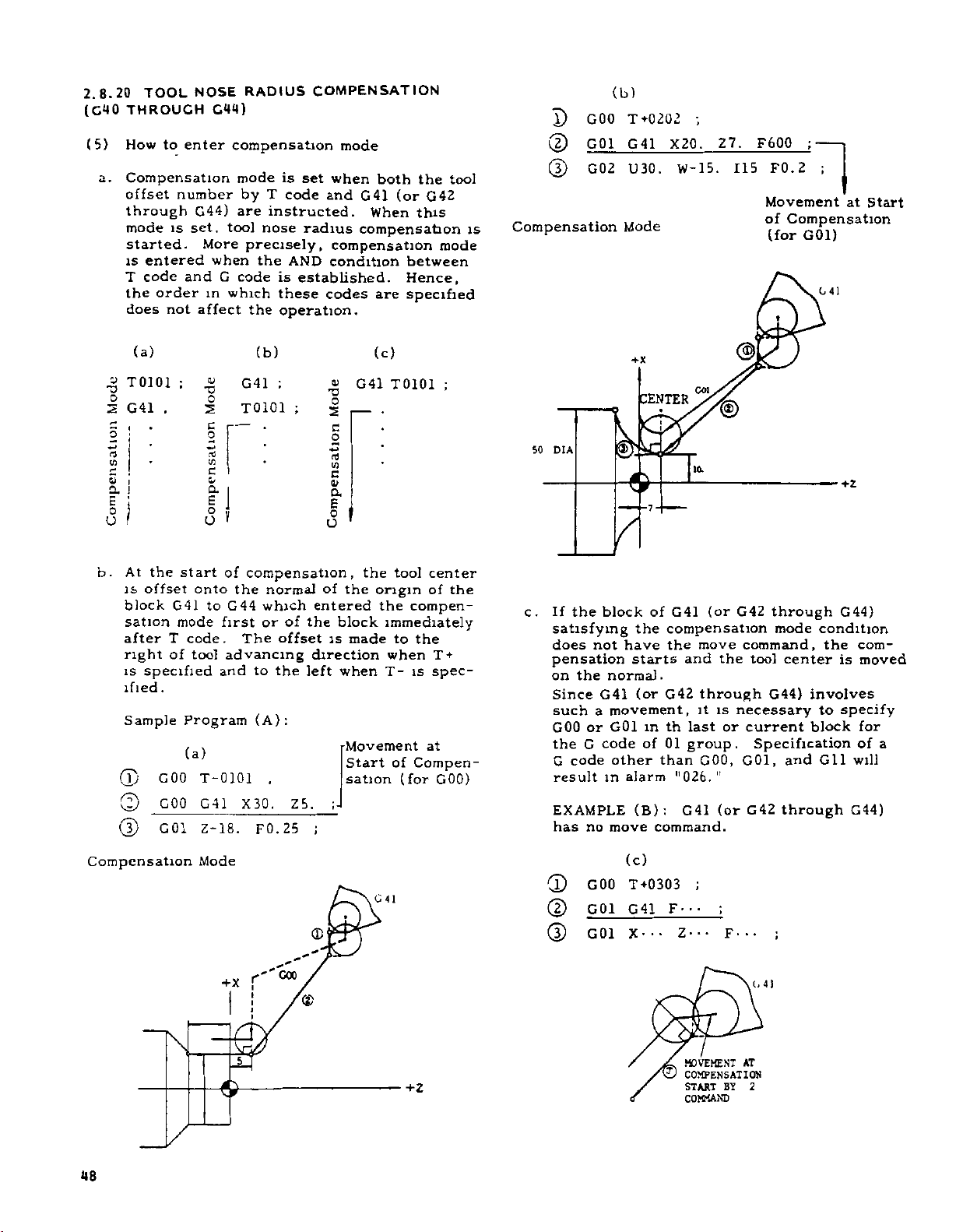
2.8.20
(C40
(5)
a.
TOOL
THROUCH
to
How
Compensation
offset
enter
number
through
mode
set,
is
started.
is
entered
code
T
the
does
and
order
not
NOSE
G44)
G44)
More
when
G
in
affect
RADIUS
compensation
mode
is
T
by
code
are
instructed.
tool
nose
precisely,
the
code
is
which
the
these
operation.
COMPENSATION
mode
set
when
and
G41
When
radius
AND
compensation
compensation
condition
established.
codes
are
both
the
(or
G42
this
between
Hence,
specified
tool
mode
is
X)
GOO
(2)
G01
(D
G02
Compensation
(b)
Mode
T
+0202
G
41
U
30
.
X20.
W-15.
;
Z7.
F600
115
;
F0.2
1
Movement
of
Compensation
G01)
(for
at
Start
G
41
(a)
«
T0101
G41
I
•
1
I
V)
E
!
Hi
a
s
:
o
o
the
At
b.
offset
is
block
sation
after
right
is
specified
ified
Sample
(T)
©
©
Compensation
;
,
G41
mode
T
of
.
G00
GOO
G01
%
I
c
C
vi
c
ii
a
E
8
start
onto
to
code.
tool
and
Program
(a)
T-0101
G41
18.
Z-
Mode
(b)
G41
T0101
J
of
compensation,
the
normal
G44
which
or
first
The
advancing
to
(A):
,
30.
X
F0.25
;
;
of
offset
the
Z
|
o
1/5
C
a
£
o
u
of
entered
the
is
direction
left
,
5
;
(c)
v
G41
.
—
E
U
'
the
the
origin
the
block
made
when
•Movement
Start
sation
I"
G
T0101
tool
;
center
of
the
compen¬
immediately
to
the
+
T
when
is
T-
spec¬
at
of
Compen¬
GOO)
(for
41
DIA
50
c.
If
satisfying
does
pensation
on
Since
such
GOO
the
G
result
EXAMPLE
has
CD
©
©
the
the
G
code
block
not
normal.
G41
movement,
a
or
G01
code
other
in
no
move
GOO
G01
G01
+x
a
/I
the
have
starts
(or
alarm
(B):
(c)
T
G
X---
CENTER
G41
of
compensation
the
and
G42
th
in
01
of
than
"026.
G41
command.
+0303
41
F-
Z---
GOi
/
10.
(or
move
through
it
last
group.
GOO,
;
•
•
©j
G42
the
necessary
is
or
"
(or
;
•
F
command,
current
GOI,
G42
•
through
mode
tool
center
G44)
involves
block
Specification
and
through
;
•
G44)
condition
com¬
the
is
moved
to
specify
for
of
Gil
will
G44)
a
48
+X
&
G00
'
,r
1,4)
CD
5
MOVEMENT
4.
.-J
COMPENSATION
START
COMMAND
BT
AT
2
Page 59
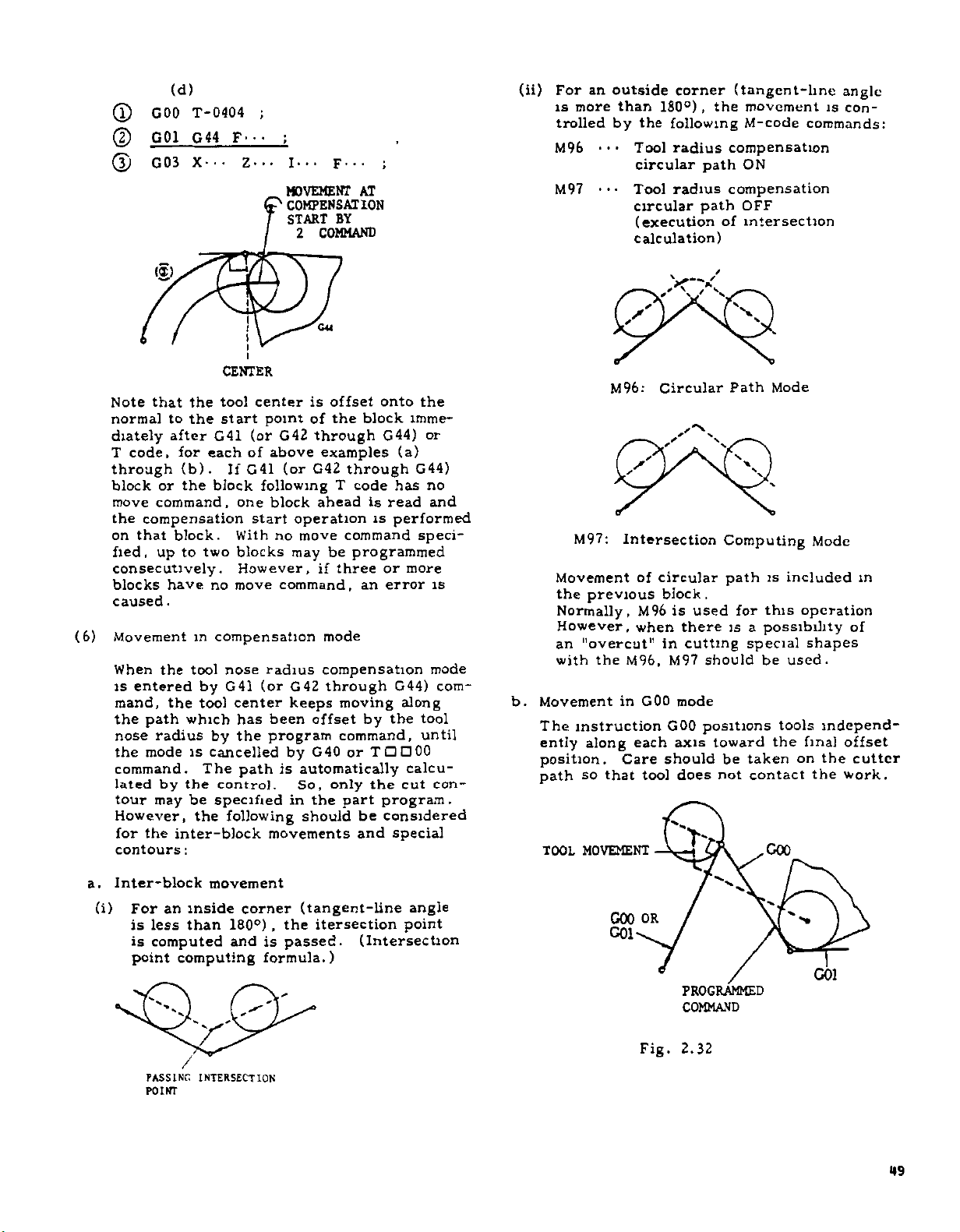
(T)
©
(D
(d)
GOO
G01
G03
T-0404
G44
X--
F---
Z-..
;
;
I--.
F
MOVEMENT
COMPENSATION
START
BY
COMMAND
2
ii)
<
•
•
AT
For
is
more
trolled
M96
M97
an
outside
than
by
the
Tool
circular
Tool
circular
(execution
calculation)
corner
180°)
following
radius
radius
(tangent-line
,
movement
the
M-code
compensation
ON
path
compensation
OFF
path
intersection
of
angle
is
con¬
commands:
Note
normal
diately
T
through
block
move
the
on
fied,
consecutively.
blocks
caused
(6)
Movement
When
is
the
However,
contours
<«>
the
that
the
to
after
code,
for
(b).
or
the
command
compensation
that
block.
to
up
have
.
m
the
tool
entered
mand,
nose
the
command.
lated
tour
for
the
which
path
radius
modeiscancelled
by
the
be
may
the
inter-block
:
CENTER
tool
start
G41
each
If
block
,
one
With
two
blocks
However,
move
no
compensation
nose
by
G41
tool
center
has
by
the
The
path
control.
specified
the
following
I
center
point
(or
G42
of
above
(or
G41
following
block
start
no
command,
radius
(or
been
program
is
movements
CM
is
offset
the
of
through
examples
G42
through
T
ahead
operation
command
move
may
be
three
if
mode
compensation
through
G42
keeps
moving
offset
command,
G40
by
or
automatically
So,
only
in
the
part
should
the
onto
G44)
has
is
read
is
performed
imme¬
(a)
G44)
speci¬
block
code
programmed
more
or
error
an
G44)
along
tool
the
by
until
TDD00
calcu¬
the
cut
program.
considered
be
special
and
or
no
and
is
mode
com¬
con¬
b.
M97:
Movement
the
previous
Normally,
However,
'’overcut"
an
with
Movement
The
instruction
ently
along
position.
so
path
MOVEMENT
TOOL
S
y
M96:
/
Intersection
M96,
the
in
Care
that
y
of
M96
when
GOO
each
tool
y
«*,
--
Circular
y'ÿ
/
y'
circular
block
is
in
M97
GOO
should
used
there
cutting
mode
axis
does
V
Computing
path
.
is
should
positions
toward
be
not
Path
for
special
taken
Mode
is
this
a
possibility
be
tools
the
contact
COO
Mode
included
operation
shapes
used.
independ¬
final
on
the
the
m
of
offset
cutter
work.
a.
Inter-block
(i)
For
less
is
computed
is
point
PASSING
POINT
inside
an
than
computing
V
X
/
INTERSECTION
movement
corner
180°)
is
and
formula.)
(tangent-line
,
the
passed.
itersection
(Intersection
angle
point
GOO
G01
OR
PROGRAMMED
COMMAND
Fig.
2.32
G01
49
Page 60

(C40
(o)
ml
TOOL
THROUGH
Movement
Programming
modi
lie
*«r
1
u
i
V
)
i
i
Coned
i.iretui
ip>‘d
g
in
NOSE
C44)
.n
lulling
1
l*
<
RADIUS
(CONT'D)
Dispensation
i
unsideration
to
not
contour.
COMPENSATION
mode
in
compensation
program
T+
a
T-
i
sr'-'*x
WliL*.
|
j
JK
THr
M9?
(Cont'd)
wedge-
OOL
CW.0T
H
1X.E
NCISI
CIT
LUII]
mode
control
tool
gives
(dwell),
ahead
blocks,
impossible
be
obtained.
G41
two
.
G41
involving
normally
radius
the
no
instructions
to
G44
or
more
in
the
F---
no
compensation
tool
path.
coordinate
control
the
and
makes
tool
and
Therefore,
are
blocks
compensation
,
movement
reads
If
calculations.
are
radius
accurate
used
two
blocks
either
instructions
reads
missing
compensation
tool
in
ensurethat,
without
plane
in
lonipcn-
mode
of
a
in
path
a
program
movement
will
ahead
and
these
such
block
When
three
be¬
can¬
after
not
Conn
d.
satiuii
The
during
calculates
blocks
G04
as
further
coordinate
or
more
comes
not
where
them,
OF
IV
command
follow
G01
M97
1
)
I
I
/
M.-7
t>n;_r
tool
A
(,.»#•.«
r-'
L.
nos<
to
ro
A
S3
T-1-
m
“1
'he
oi
I
tool
2R
i
t
P
diameter
T-
M97
PROGRAM
THAT
2R
WEDGE
movement
TOOL
CAN
can
GET
so
IS
be
MADE
NOSE
IN
that
SO
OF
THE
the
in
the
e.
g
-A
PROGRAMMED
(GO!
Tf
CONTOUR
MODE)
4
c
1
MODE)
CONTOUR
PROCRAMMED
(GO
1
U---
G04
M-
;
M40
no
movement
If
in
three
the
of
is
it
three
dummy
dummy
on
block
on
offset
of
Use
If
in
offset
a
The
movement.
purpose
tool
the
address
used
are
I:
X-axis
K.
Z-axis
consecutive
the
normal
immediate
dummy
impossible
or
more
the
normal
block
block
This
of
providing
nose
radius
of
this
.
dummy
dummy
Compensation
made
blocks
instruction
blocks
line
blocks
to
specify
consecutive
line
may
be
does
block
the
computation.
dummy
command
command
the
by
without
,
at
before
is
inserted.
not
specifieid
is
data
command,
is
normally
or
two
move
is
programmed
center
tool
the
end
them
a
move
blocks
satisfactory,
not
cause
an
necessary
I
(incremental).
incremental)
<
less
cotnmanc
point
command
and
actual
for
For
and
is
the
the
for
the
K
.
\
V
T-
it'
Page 61
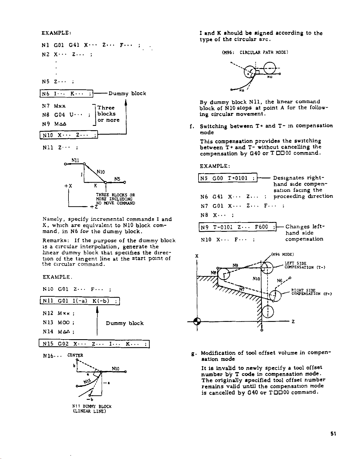
EXAMPLE:
G01
N
1
2
N
X-
Z--
N5
•
I-
N6
Mxx
N7
G04
N8
MAA
N9
X-
NIO
1
Z--
Nil
Namely,
K,
which
mand,
Remarks:
is
a
circular
linear
tion
the
EXAMPLE.
NIO
Nil
N
N13
N
12
14
dummy
of
circular
G01
G01
Mxx
MOO
MAA
G41
•
Z-
•K-•
U-
•
•
Nil
o-
+X
specify
are
N6
in
the
Z---
I(-a)
X---
;
••
;
*
-
;
•
•
••
Z-
;
1
K
THREE
MORE
Z
+
incremental
equivalent
for
the
the
If
purpose
interpolation,
block
tangent
command.
F---
K(-b)
Z---
Three
blocks
or
NIO
NO
MOVE
dummy
that
line
more
Dummy
•
•
F
Dummy
N5
BLOCKS
INCLUDING
OR
COMMAND
commands
NIO
to
block.
of
the
generate
specifies
at
the
;
block
;
block
block
dummy
start
the
com¬
the
direc¬
point
I
block
and
of
and
I
type
By
block
ing
Switching
f.
mode
This
between
compensation
EXAMPLE:
5
N
N6
N7
N8
N9
NIO
'////,
should
K
the
of
(M96:
*v
of
block
NIO
dummy
circular
between
compensation
T+
T+0101
GOO
G41
X--X-
G01
X---
;
T-0101
••
X-
N9
N8
Gr
signed
be
circular
CIRCULAR
arc.
PATH
•ska
rt
NIS
'
Nil,
stops
movement.
and
by
•
•
Z--*
•
•
F
provides
T-
G40
;
Z...
Z.
F600
•''1
NIO
point
at
and
T*
without
or
;
F-
•
-A
/
/
V.
/
$
/
according
MODE)
NIO
linear
the
T-
T
Designates
hand
sation
proceeding
•
;
—
.(M96
j
!
to
command
the
for
A
m
the
follow¬
compensation
switching
cancelling
command.
right-
compen¬
side
facing
direction
;
Changes
side
hand
compensation
MODE)
LEFT
SIDE
COMPENSATION
RIGHT
SIDE
COMPENSATION
Z
the
the
the
left-
(T-)
(Tf)
N15
16
N
•
•
G02
•
X-
CENTER
‘l
su
N1
1
(LINEAR
Z
•
t
-b
DUMMY
LINE)
•
•
I
a
—
BLOCK
•
•
NIO
;
•
•
•
K
•
compen¬
Modification
g.
sation
It
number
The
remains
is
mode
invalid
is
by
originally
valid
cancelled
of
to
code
T
by
tool
newly
in
specified
until
G40
offset
volume
specify
compensation
tool
the
compensation
or
TDOOO
in
tool
a
offset
command.
offset
mode.
number
mode
51
Page 62

2.8.20
(C40
((>)
(7)
.
a
2
r
i
o
V
.a
a
E
0
O
b.
TOOL
THROUCH
Movum
However,
changed
tents
tool
fied
operation.
tool
offset
the
with
buffer
to
How
When
sation
nose
tool
,
40
G
T0100
I
pon
center
end
point
mode,
for
that
specified.
which
specified
portion
Then,
tool
nose
command
NOSE
C44)
MI
in
compensation
the
too!
by
varying
corresponding
offset
After
number
block
newly
.
T>'
cancel
G40
mode
,
termination
is
or
results
is
the
compensation
TDDOO
or
cancelled,
is
radius
T0100
,
40
G
offset
of
the
block
the
which
(Consequently,
in
in
G40
produced.)
moves
tool
matches
specified
RADIUS
(CONT'D)
nose
the
to
number,
this
is
made
stored
/T
is
compensation
,
of
compensation,
onto
the
final
immediately
G40
or
acute-angle
or
TDDOO
so
end
the
G40
in
COMPENSATION
mode
(Cont'd)
radius
offset
the
by
value
memory
originally
means
modification,
valid
beginning
in
the
BLOCK
NEWLY
OF
TOOL
VALUE
READ
CHANCE
RADIUS
TIP
mode
operation.
T0100
line
in
compensation
before
has
a
retracting
contour
virtual
the
of
TDDOO
compen¬
specified,
terminating
E
;
G40
normal
block
TDDOO
that
point
or
if
block,
may
speci¬
of
MDI
the
prefetch
AFTER
NOSE
the
;
the
to
been
is
no
uncut
the
block.
be
con¬
new
tool
the
move
©
©
©
©
c.
©Pi
(T
+0202,
G01
G01
G01
GOO
12
2
the
If
sation
mand
specified
SI
1
Cb
lb
REFERENCE
ij-
(b)
G41)
X
U
G
T
1
block
cancel)
,
the
MF
ION
I
I
Til.
(IIO.HU)
•
•
24.
40
+0200
virtual
end
-..IE
01
X
of
TOOI
I
FM
THb
TOOL.
coo
/
&
•
Z-
F0.3
80
;
+x
G40
does
point.
*\>s
\s-
i
1'OslTlOM
bOR
THE
MOTION
PLETION
PENSATION
•
F
,
.
Z40.
)
(Nose
not
tool
1
-
•
4
have
nose
©w
F6.
radius
moves
ON
;
the
COM¬
OF
(GOO)
G41
+z
compen¬
move
to
COM¬
com¬
the
EXAMPLE
(T
o
w
J)
|f®
u"L©
©
©
52
(a)
+0101
G02
G01
GOO
T0100
,
A
G41)
U20.
G
40
,
F0.25
X110.
MOTION
TION
(GOO)
;
Z40.
COMPLE¬
ON
COMPENSATION
OF
;
Page 63
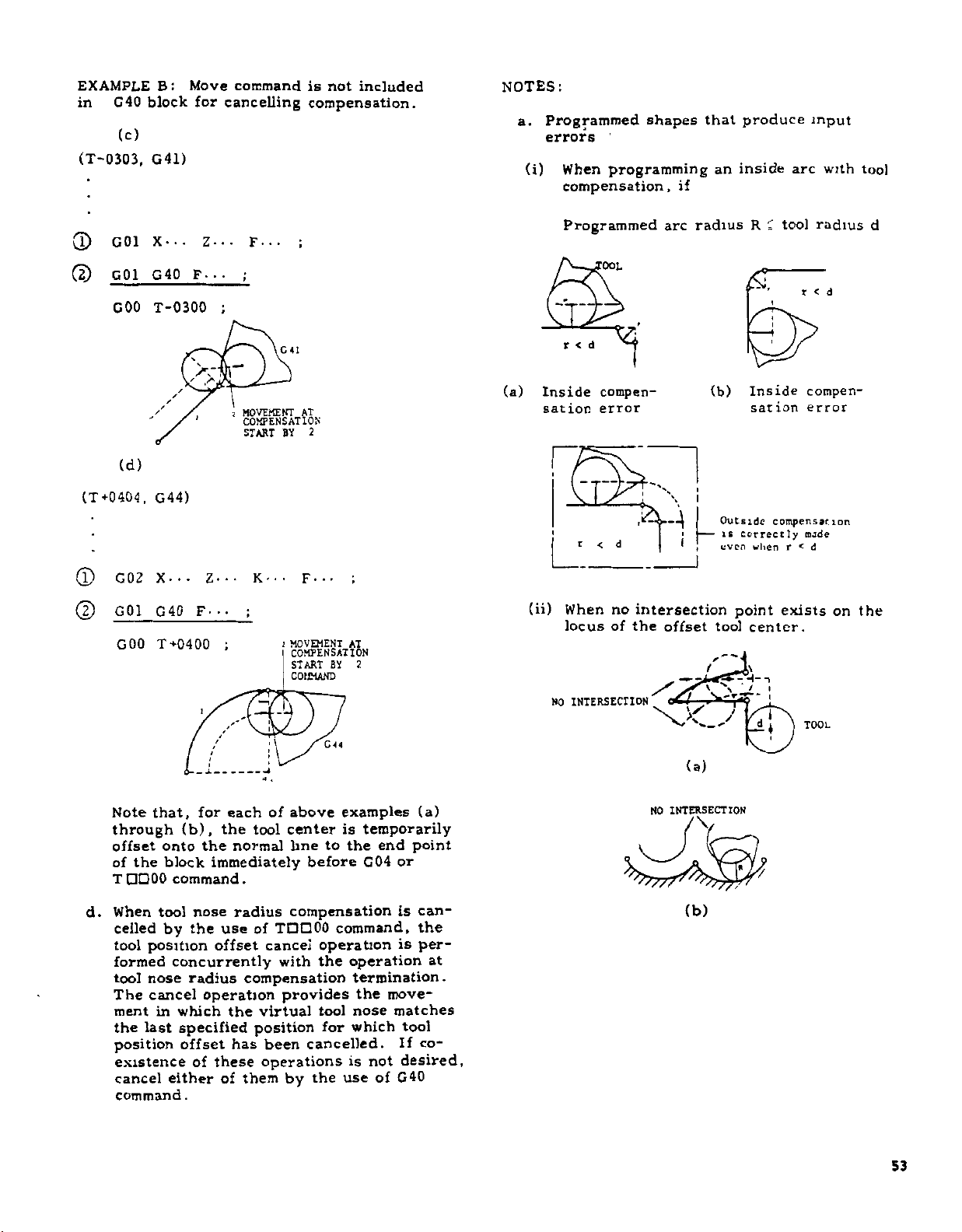
EXAMPLE
G40
in
(c)
(T-0303,
G01
0
(2)
G01
COO
:
B
block
G41)
X--.
G40
T-0300
/
Move
for
Z-..
F---
wan
command
cancelling
F-..
:
;
MOVEMENT
2
COMPENSATION
START
is
compensation.
;
C
41
AT
2
BY
not
included
NOTES:
Programmed
a.
errors
(i)
(a)
Inside
sation
When
programming
compensation,
Programmed
'OOL
u
d
r
<
1
compen¬
error
shapes
arc
if
that
an
radius
(b)
produce
inside
tool
R
C
<ST
Inside
sation
input
arc
radius
r
<
compen¬
error
with
d
tool
d
(T
®
(
2
+0404
)
d.
(d)
G44)
,
X-
G02
G01
G
GOO
that,
Note
through
offset
of
the
TQDOO
When
celled
tool
position
formed
nose
tool
cancel
The
ment
in
last
the
position
existence
cancel
command
•
-
40
F
T
+0400
i
for
(b),
the
onto
block
command.
nose
tool
by
the
concurrently
radius
operation
which
specified
offset
of
either
.
•
Z-
K-
-.
;
/
each
the
tool
normal
immediately
radius
of
use
offset
compensation
virtual
the
position
has
been
these
operations
of
them
•
:
of
•
•
F
•
!
MOVEMENT
I
COMPENSATION
START
COMMAND
C
above
center
to
hne
before
compensation
TDD00
cancel
operation
the
with
provides
tool
cancelled.
the
by
for
AT
2
BT
44
examples
temporarily
is
the
G04
command,
operation
termination.
the
nose
which
not
is
of
use
end
or
is
is
move¬
matches
tool
If
desired,
G40
(a)
point
can¬
the
per¬
at
co¬
(ii)
n
L'J
When
locus
NO
J2
no
intersection
of
the
INTERSECTION
NO
\
1
offset
-A*-,
\x_y
(a)
INTERSECTION
\
(b)
Outside
is
even
tool
correctly
when
point
center.
-i
-ii
tl//
compensation
mode
<
r
exists
I
TOOL
d
on
the
53
Page 64
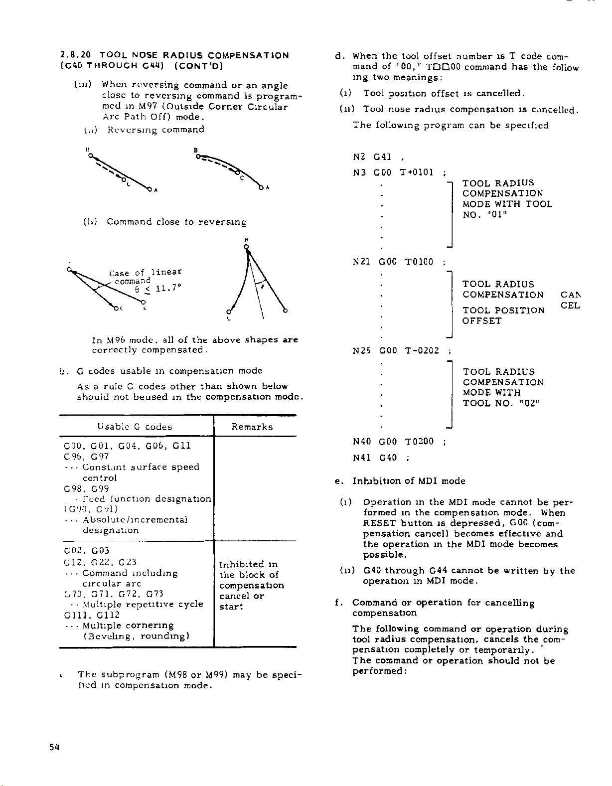
2.8.20
(C40
(m)
TOOL
THROUCH
When
close
med
Arc
t.i)
Reversing
NOSE
C44)
reversing
to
reversing
in
M97
Path
RADIUS
(Outside
Off)
command
(CONT'D)
command
command
mode.
COMPENSATION
or
Corner
angle
an
is
program¬
Circular
d.
(i)
(11)
When
mand
ing
Tool
Tool
The
the
"00,”
of
two
meanings:
position
nose
following
tool
offset
TDD00
offset
radius
program
number
command
cancelled.
is
compensation
be
can
is
T
has
specified
code
the
is
cancelled.
com¬
follow
n
V
(b)
Command
Case
„
M96
In
correctly
G
codes
b.
rule
As
a
should
Usable
GOO,
90,
C.
•
•
•
0
1
G
97
G
Constant
,
control
,
C
G
98
99
•
(
90
G
•
•
•
function
Teed
,
G
9
1
Absolute/incremental
designation
G02.
G03
,
,
22
G
2
1
G
•
•
Command
circular
,
7
G
•
Multiple
Multiple
•
1
GI12
070.
•
Gill,
-
(Beveling,
The
c
fied
subprogram
in
command
c
6
mode,
<
linear
of
compensated.
usable
codes
G
not
beused
G
codes
GOO,
,
04
G
surface
)
23
G
including
arc
G72,
G73
repetitive
cornering
rounding)
compensation
A
to
close
11.7°
of
all
in
compensation
other
the
in
Gil
speed
designation
cycle
(M98
or
mode.
B
reversing
above
the
than
compensation
Inhibited
the
compensation
cancel
start
M99)
c
H
c
shapes
mode
shown
Remarks
block
may
or
be
A
»
below
in
of
speci¬
are
mode.
N
N
N
N
N
N41
e.
Inhibition
(l)
(u)
Command
f.
compensation
The
tool
pensation
The
performed:
2
41
G
GOO
3
GOO
21
25
GOO
40
GOO
G40
Operation
formed
RESET
pensation
operation
the
possible
G40
through
operation
following
radius
command
,
T
+0101
T0100
T-0202
T0200
;
of
MDI
the
in
the
m
button
cancel)
in
.
G44
in
MDI
or
operation
command
compensation,
completely
or
TOOL
COMPENSATION
MODE
NO.
TOOL
COMPENSATION
TOOL
OFFSET
;
TOOL
COMPENSATION
MODE
TOOL
;
mode
MDI
mode
compensation
is
depressed,
becomes
the
MDI
cannot
mode.
for
or
or
temporarily.
operation
RADIUS
WITH
"01"
RADIUS
POSITION
RADIUS
WITH
NO.
cannot
mode.
G00
effective
mode
be
written
cancelling
operation
cancels
should
TOOL
"02"
be
When
(com¬
becomes
by
during
com¬
the
not
be
CAN
CEL
per¬
and
the
54
Page 65

1.
2.
3.
4.
5.
6*
g.
Commands
The
for
1.
2.
3.
4.
5.
6.
7.
h.
Even
sation
circular
than
follow
directly
those
Three
without
MOO
or
M-code
for
eter
advance
(6
Max)
M02,
Reset
Turning
following
they
G28,
50,
G
G74,
G90,
G31
G68,
122,
G
in
and
the
the
which
consecutive
move
M01
command
set
by
stopping
reading
M30
commands
operation
off
causing
commands
cause
G29,
G
51
75,
G
G92,
-
G35
G69
G
123
M96
mode
circular
arc
distances
fixed
corner
point
to
are
command
param¬
power
error
errors.
G30
G76
94
G
(tool
values
circular
.
B
set
blocks
supply
arc
AX,
,
The
by
/
must
nose
radius
are
path
AZ
tool
the
arc
fixed
parameter
zsX/2
Temporarily
>
cancelled
Completely
>
cancelled
be
not
compen¬
on),
smaller
are
not
does
path
but
values
#6230.
given,
if
moves
are
EXAMPLE
NJ
CSO
X140
N
2
COO
S
(COO)
3
N
C01
N4
MS
N
N
N
N9
N
Nil
N
N
N
N
N
N
N
rn
!
6
7
8
10
12
13
14
1
16
17
1
no
Z0
X
20
Z-20
30
X
C
W-
12
XS0
Cll
CO)
G22
CO)
G04
(COD
S
X
120
C00
40
C
5
D1A
r
90
D1A
20
no
--
A:
o
n
1700
M03
T*0202
.
,
-
S360
.
CANCEL
TOOL
COMPENbAl
bl
RO
BEVELING
C41
X0
Z5
F0
2
w-
15
SHOO
.
20
13
S700
K-3
X-70
90
2-90
X
X110
U0
140
X
Z-110
R20
,
300
S
DWELL
-
.
70200
30
Z
""COMPENSATION
N
16
O
.
CENTER
TOOL
PATH
'
i
50
MM
3
i
R3
r—
D1A
BEVELING'
ROUNDING
20
-90.
/
D1A
30
)5
20
70
--
NOSE
BLOCK
ART
LADING
CIRCULAR
ARC
,
-
RADIUS
TOOL
OMPEN-A
COMPLETE
COMPENSAl
START
15
ION
BY
NObE
1
ION
-
-
BLOCK
.....
TOOL
POSITION
OFFSET
MOTION
PROGRAMMED
CONTOUR
K>\
+x
I
l
:
FT)
K
'
T
20
PlAÿft-g)
N4,
20
5
TOOL
COVJ'I
TION
-£ÿ-02
-
S
i
/
f
t
*
7N3
I
t
t
j
i
l
«
•
K
1/
NOsh
NhA-
TOOL
In
case
PROGRAMMED
of
COMMAND
A
A
S
X/2
S
Z
NEGNR:
S
NEGNR
NEGNR
Constant
parameter
TOOL
MOVEMENT
value
for
setting
55
Page 66

2.8.20
(C40
l)
(
TOOL
THROUGH
to
How
RADIUS
calicos
C44)
compensation
COMPENSATION
(CONT'D)
mode
(Cont'd)
~\
PRESENT
OF
TOOL
POSITION
TIP
\
is
T-t-
(b)
decided
043
T+
042
043ÿ
T-
042
t
All
raj
C43
-'L.
;
:
L.
04
1
T—
*
i
4
CM
T—
Round
by
(a)
r
/
setting
T+
+
T-
Normal
042
T-
043
T+
Insert
X
Gai
7
x
T+
Insert
G4J
T+
x
044
T-
(G
of
side
J
\
code
virtual
*
042
T+
043
T-
C44
-J
I
i
*T-
All
to
044
T-
C41
T_
CM
T-*-
041
T+
Round
be
tool
Virtual
Tool
used
In«erc
Nos*
nose.)
(2)
50
G
When
instead
dinate
values
absolute
When
the
incremental
useful.
groups.
length
second
incremental
coordinate
G50
+x
POSITION
THE
GROUP
U---
U100.
SECOND
the
addresses
of
is
set
(X-axis)
U
coordinate
the
tools
The
Then,
of
the
group
B
ABSOLUTE
POINT
Fig.
W-.-
X
and
by
up
are
G50
tools
the
reference
of
tools
G50
command
system
W-100
100
50
OF
ZERO
0)
(0,
2.34
(Incremental
;
U
Z,
the
adding
and
previously
very
(addresses
should
difference
can
;
G50
OF
(C50
A
and
new
(Z-axis)
W
different
be
tool
can
be
and
be
stored.
•
•
COMMAND
REFERENCE
i
G50)
W
are
specified
absolute
incremental
set.
in
U,
divided
between
and
that
set
at
an
absolute
Setting
Position
•
•
•
•
Z
X
coor¬
to
the
length,
W)
is
into
the
of
the
the
of
B
POSITION
TOOL
,)
••
two
2.8.21
POINT
Absolute
mo\
coordinate
the
on
(1)
56
2.33
Fig.
Code
T
of
II
PROCRAMMING
(G50)
coordinate
e
command.
system,
absolute
G
50
X-
command
This
tool
tip
values
The
X
and
es
and
tip
Therefore,
set.
command
Relations
lor
After
coordinate
•
•
Z
the
with
Z
are
the
specifies
Tool
system
all
•
•
makes
absolute
a
the
absolute
between
Nose
OF
setting
motions
the
coordinates
sign
distances
zero
can
it
the
G
Radius
ABSOLUTE
should
the
up
can
system.
present
following
point
said
be
absolute
code
Compensation
ZERO
set
be
absolute
commanded
be
position
(X,
the
between
(0,
that
zero
and
before
Z)
address¬
tool
0)
to
"G50
point."
-*-Z
Fig.
2.35
of
.
be
Page 67

(3)
NOTES
1.
2.
3.
Assume
tool,
and
coordinate
ing
G50
then,
tool
the
sation
to
If
with
position
figure
point
3
N
N4
10
N
the
select
operation,
G50
GOO
coordinate
the
pensation
shown
above,
programmed
for
When
in
GOO
This
offset
G
50
in
G
all
:
T,
the
should
designates
G50
GOO
is
the
codes,
tool
block
motion.
X-..
S500
a
specified
specified
S*
•
G50
separate
system
G50
set
setting.
should
and
the
that
perform
X80.
the
compensation
below
.
A
X80.
T0101
GOO
T0202
-f-X
Z-62w»
'
C50
POSITION
:
I
TOOL
reference
is
applied
on
noses
S
and
following
be
M03
nonmodal
M,
and
the
in
;
or
•
feature
be
tool
radius
tool
No.
the
system
Z62.
tool
No.
and
and
Z62.
;
dX,
7H
COMMAND
AT
NO
01
2.36
Fig.
system
tool
to
the
tool
a
single
.
M
commands
programmed
traverse
the
Z-..
T0101
code
G
block.
S,
and
same
block.
G50
T
and
is
commanded
compensation
01
setting
for
this
02
value
peroform
the
tool
TOOL
i
setting
and
the
movement
coordinate
that
containing
in
;
which
Generally,
codes
T
*
•
•
not
after
is
the
of
tool:
which
the
No.
02
NO.
+z
tool
other
are
programmed
the
rate
is
Note
;
command
for
coordinate
the
reference
the
has
shown
compen¬
02
is
performed
position
tool
may
system
block.
for
valid
the
cannot
that
tool
are
follow¬
the
in
moves
com¬
as
be
G50,
tool
only
other
be
a
is
off¬
cancelled
When
4.
sent
(0,
system
5.
The
dinate
ABSOLUTE"
6.
The
affected
system
ations
(i)
(ii)
(iii)
7.
When
Work
effective.
2.8.22
50)
(G
t
function
This
with
S
(1)
G50S---
Four
specifies
in
limit
spindle
(2)
In
mode,
as
too
the
EXAMPLE
The
2000
NOTES:
Maximum
1.
be
4.
2.
The
cleared
3.
In
address
machine
designation,
the
position
0).
Therefore,
should
current
system
coordinate
by
is
:
reset
The
2,
4.
3.
4.
formed.
XO
G50
and
mode
The
power
setting
Coordinate
MAXIMUM
4-
it
dig
digits
rpm.
issued
is
speed
(Constant
G96
when
current
the
small,
limit.
S2000
G50
maximum
rpm
displayed
3.
2.1
Display
specified
by
of
case
S
tool
power
supply
of
tool
be
position
is
shown
current
of
set
system
reset
operation.
reset
by
operation
POSITION
;
command
Z0
is
executed.
turned
is
work
System
SPINDLE-SPEED
used
for
is
designation
following
the
upper
an
If
S
in
is
spindle
X-coordinate
the
spindle
;
spindle
.
spindle
reset
S
is
speed
on
the
of
maximum
operation.
4-digit
not
shown
builder's
this
is
is
set
the
absolute
before
up
the
of
in
position
which
of
one
by
ABSOLUTE)
on
coordinate
Shift
the
option.
the
limit
command
subsequent
governed
Surface
speed
speed
speed
specified
CRT
Command
spindle
designation
by
manual.
function
turned
to
the
coordinate
coordinate
operation.
tool
in
"POSITION
display.
was
The
the
following
ORG
key
written
is
again.
system
2.6.5
in
SETTING
control
provided
address
spindle
of
exceeding
blocks,
at
the
Speed
rises
of
the
is
clipped
is
clipped
display.
Data.
speed
B
rpm.
For
cannot
on,
the
G50
coor¬
set
is
not
coordinate
oper¬
(see
is
per¬
in
by
will
S
speed
the
the
upper
Control)
too
up
tool
by
G50
Refer
is
,
unit
Refer
2-digit
S
used.
be
pre¬
MDI
G50,
be
limit.
fast
is
at
can
to
not
of
to
57
Page 68

2.8.23
(C50T,
WORK
G51)
COORDINATE
i
MULTI-SHIFT
Z
+
This
Work
lienee
l.trmliur
The
"work
work
the
G50T
ing
ment
gramming
dinate
(1)
.
a
b
.
c
feature
Measured
it
with
coordinate
position
system
Tool
is
It
write
the
ing
Value
he
'I
memory
tool
of
below
1
2
3
For
tool
for
No.
Tool
used
is
Value
is
necessary
paragraph
purpose
as
used
coordinate
of
be
may
throughout
coordinate
necessary,
the
coordinate
tool
coordinate
procedure,
Direct
number
units
offset
Number
offset
combinations
memory
0
to
0to16
0
to
ease
of
No.
etc.,
51.
Coordinate
Memory
in
Direct
of
this
system"
absolute
system
each
tool.
performed
value
before
see
Input."
available
of
corresponds
memory
tool
of
9
50
use,
write
01
in
as
shown
combination
Input'1
for
the
6.2.3.
feature
with
zero
setting
In
with
the
memory
specifying
data
memory.
"6.2.3,
combinations
the
tool
coordinate
below:
with
option.
programmer
to
is
retain
a
certain
point
by
the
at
other
entire
words,
a
single
machining
(number)
G50T,
for
each
For
the
Work
Measured
coordinate
tool
to
the
number
Available
coordinate
number
to
59
51
to
66
51
80
to
51
coordinate
memory
Tool
No.
"6.2.3,
to
a
point
perform¬
replace¬
pro¬
coor¬
tool
to
writ¬
as
shown
tool
memory
(9)
(16)
(30)
data
be
on
.
Zln
Zm
"WORK
OPERATOR
DIRECT
At
WORKPIECE
COORDINATE
AT
INPUT"
Fig.
TV
"WORK
OPERATION.
2.37
Tn
TOOL
POSITION
CURRENT
BY
DISPLAY
Xtn/2
SYSTEM"
MEASURED
IDF
SI
(SKI
SET
vr
I
INDICATH1
POSITION
(0,0)
NOTE
BY
VALUE
111
1)
to
(2)
a.
Work
G50
Using
system
the
following
coordinate
TOD
A A
TIL
command,
this
for
each
system
Specifies
(00
Specifies
memory
of
work
setting
50)
to
number
set
X-axis
coordinate
tool
tool
the
offset
coordinate
coordinate
and
(G50T)
(51
Z-axis
system
number
80)
to
with
setting
value:
Work
coordinate
system
setting
value
Content
of
programmed
coordinate
one
1:
"Unit
which
Note
the
(EXTERNAL)
tion
display
tool
memory
current
is
screen
(POS)
=
shown
on
Unit
position
(Note
Content
+
programmed
offset
position
in
of
the
CRT
current
value
1)
of
memory
value"
"POSITION
current
display.
+
tool
is
posi¬
58
"00"
a
in
given
work
in
field
specifies
contents
the
memory
the
unit
coordinate
is
tool
the
AA.
the
system
being
specified
is
position
current
set
offset
work
setting
of
tool
zero.
(for
system
correctly
with
posi¬
as
51
52
80
01
02
30
b.
Usually,
number
EXAMPLE:
G50
specify
specification
T5100
T
;
"00"
coordinate
above
-x,
the
:
with
offset
at
-2
,
the
operator
program
It
ory
Xln
assumed
is
contains
and
Ztn
that
the
for
the
following
tool
each
tool
coordinate
coordinate
Tn.
d.
mem¬
data
When
the
tool
the
slide
example,
tion
display)
defined
shown
by
below
Page 69

G50
c.
By
set
This
coordinate
the
and
by
(3)
Return
a.
By
point
current
X-axis
With
b.
coordinate
start
(0,
command
point
G51
c.
a
NOTES:
G50
1.
are
2.
When
#6005D5
display
3.
G51
two
Consequently,
command,
together
setting
+X
T0000
this
with
means
content
the
the
G51
a
0)
command
single
T
valid
this
;
block
G50
GOO
at
command
Zt>
T
COORDINATE
WORK
,
command,
unit
the
that
system
of
content
specification
to
current
,
command,
rapid
position
and
Z-axis.
part
program
system
point
is
in
principle.
facilitates
(0,
0)
after
block
and
G51
only
function
(G50
to
0
off)
is
commands.
T0000
X0
Z0
the
with
the
tool
T1
AT
(-x,
z
—
Fig.
current
the
tool
of
traverse
value
the
should
basis.
are
the
for
preset
.
equivalent
is
;
:
after
tool
work
the
offset
WHEN
TOOL
A
GIVEN
-r).
iTTT
*\
!
WHEN
M..*
AT
~x
/
2
Xn/2
(-x/2)
x)
(
+Ztt
—
SYSTEM
2.38
the
coordinate
canceling
setting
coordinate
tool
offset
T0000.
of
position
tool
is
rate
is
that
setting,
current
Hence,
the
return
completion
always
nonmodal
specified
is
used,
of
execution
the
offset
number
coordinate
number
___
IS
SLIDE
POSITION
J
TOOL
POSITION
-t-Xu/2
position
of
is
performed
memory
memory
origin
returned
where
(0,
0),
uses
work
the
position
the
of
be
codes
G
blocks.
set
POS-EXTERNAL
the
to
IS
SLIDE
0)
(0,
+Z
COORDINATE
SYSTEM
SET
THESE
system
value.
work
the
(G51)
to
the
on
both
machining
value
of
use
start
the
to
machining.
specified
which
parameter
following
this
of
cancelled
is
=
=
IS
WITH
VALUES.
is
with
"0"
"0"
the
unit
G51
on
4.
5.
6.
When
ting
System
The
work
rent
is
It
The
cannot
EXAMPLE
(The
(0,
G50
Nl
N
2
GOO
(Machining
20
N
N21
N
22
(Machinig
40
N
Note
and
compensation
during
may
taper
the
is
performed,
Shift"
current
coordinate
position
not
shown
work
be
start
0))
T5100
T0101
X*
GOO
50
T5200
G
T0202
GOO
51
G
1:
T0202
machining,
also
machining.
+
x
G50
work
T
is
position
system
value
in
coordinate
cancelled
A:
point
;
-
M03
by
tool
•
•
Z-
;
;
tool
by
;
tool
The
commands
for
used
be
TO:
i
MI
&JJ
\
N20
WOW
HACHINSNC
UA
COOKHAAU
coordinate
”2.6.5,
valid.
made
of
"POSITION
POSITION
system
by
current
is
Work
setting
S100
Selection
(Note
No.
_
•
•
:
-
-
-
No.
Return
display
position
may
wear.
tool
the
the
for
r
—
r
TO:
COORDINATE
tl
IL
KAWU
mill
SYSTEM
Work
tool
the
is
shown
EXTERNAL.
set
reset
a
position
coordinate
for
;
1)
.
01)
Positioning
point.
coordinate
Work
tem
setting
02.
No.
Selection
02
No.
02)
current
to
0)
(
,
0
offset
be
position
tool
compensation
Tnl'V
CURRENT
\
1
DISPLAY
N
2
STSTIM
N.,
O!,
TOOI
I'S
IMIS
system
Coordinate
in
ABSOLUTE."
by
operation.
tool
of
(Note
.
used
When
\
0}
system,
"00."
to
in
tool
of
in
l’0»]JUJh
(U,
the
set
the
cur¬
T
G50
display
system
No.
No.
a
to
for
tool
tool
1)
.
position
101
TO
the
for
specified
offset
U)
set¬
01.
01
given
sys¬
for
59
Page 70

2.8.23
(C50T.
WORK
51
C
NOTES
COORDINATE
)
.
MULTI-SHIFT
N
N2
1
50
G
GOO
5100
T
T0101
;
M03
S1000
.
EXAMPLE
If
following
program
tool
correctly
tion
N
N
N
A')
N
I
WORK
t
OORDTNAT*
.VSItM
This
at
ting
work
approach
the
.
1
2
3
4
+x
!
point
X
Z
machining
program
is
the
to
T5100
G50
G0101
S150
G96
X20.
GOO
B
A
APPROACH
TOOL
because
is
B
with
coordinate
(-20.)
=
(-27.5)
=
B.
which
is
interrupted
restarted
machining
moves
without
start
to
the
;
.
;
M03
STARTED
OF
CURRENT
DISPLAY
,
AT
INTERRUPTION
MACHINING
Z2.5
PROGRAM
POSITION
POSITION
AFTER
HACHININC
-
TJC1™
-
P80
COORDINATE
b
IX
performs
the
following
position
POSITION
-
-
(80.)
+
+
N1
MEMORY
60
40
G50
coordinate
system,
A
unchanged:
(40.)
(20
=
was
first
THE
(-20
,-27.5)
CURRENT
0)
(0,
,
1
T5100
values
thus
60.
12.5
=
started
returning
point
approach
START
POSITION
S)
system
to
keeping
by
and
,
the
POSITION
DISPLAY
;
command
retain
the
the
tool
posi¬
set¬
the
the
(Machined
N25
26
N
N27
r-
28
N
N48
The
by
x
=
Z
=
+x
Z=-L-l
ksz
TOOOO
X-50.
GOO
G50
T5200
T02020
GOO
(Machining
;
G51
coordinate
this
command
(-so.)
(-35.)
110
T02
+
+
by
,
••
40.
40.
D1A
by
no.
100
T01)
Z-35.
Tool
of
display
;
M03
T02)
system
are
=
=
TQ2
/
f
f
A—
47.5
DIA
-35.
701
replacement
T02
S800
setting
as
60.
5.
Pi
Q
.
-*TOI
;
current
is
(-50,
follows:
r*
-so.
/
position
-35)
;
values
MACHINING
POSITION
I
CURRENT
DISPLAY
2
position
.
START
-
POSITION
(0,
0)
60
EXAMPLE
This
example
replacement
each
from
coordinate
No.
51
52
C.
other,
Too!
shows
position
system
Coordinate
100.
110.
X
and
setting
program
a
of
each
the
tool
values
.
Memory
for
for
Z
47.5
40.
which
different
is
work
the
X-60.
DIA
WORK
COORDINATE
+Z
SYSTEM
Page 71

2.8.24
Special
or
user
registered
programs
command
These
user
macro
in
the
Main
USER
programs
the
by
in
can
to
execute
special
body,
same
format
Program
MACRO
written
use
the
part
be
called
programs
which
of
them.
as
a
a
(C65
AND
the
by
group
program
the
by
are
can
be
subprogram
User
C66)
machine
of
instructions
memory.
use
of
referred
written
Macro
programs
called
in
this
body
or,
in
calling
makes
to
the
user
is
simply,
the
a
user
it
vari¬
macro
that
pro¬
sometimes
following
the
"macro
Macro
body
designation"
main
the
real
the
This
of
specific
user
program"
Call
may
program
numbers
enables
macro
Commands
be
"argument
The
G65
builder
These
or
to
and
are
G66
as
the
stored
macro
possible
ables
to
run
vide
this
In
referred
macro
"
in
tool
body
to
assign
the
series
a
as
movements.
manual,
as
to
.
"
from
body.
.
User
macro
manners
:
Body
2.8.24.1
user
A
five
r
G65
P9001
(Argument
Designation)
)
Main
Program
M98
P
However,
.
allows
(1)
Use
(2)
Computation
constants.
(3)
Use
branch.
al
These
to
provide
complicated
1234
of
variables.
of
control
features
a
computations
,
;
unlike
between
commands
enable
generalized
Variable
Operation
Control
M99
Subprogram
01234
M99
a
subprogram,
variables
the
program
and
1
Command
;
;
;
a
or
as
such
macro
user
that
decisions.
Command
user
macro
between
a
condition¬
body
requires
No.
(
1)
G65
The
1
2
3
4
5
Type
Simple
Modal
Call
G
Call
Call
Simple
•
P
macro
specified
default
The
argument
of
an
specify
it
designation"
the
"local
details,
(2)
Modal
G66
P..-
This
command
by
program
is
mand
.
times
;
G67
command
This
call
call
by
code
by
by
Call
•
L-
program,
P,
by
value
in
(argument
is
variables"
see
3
Call
L-**
number
executed,
of
Call
arbitrary
M
code
T
code
(G65)
•
•
(argument
is
called
of
to
the
the
assignment
ARGUMENT
3
(G66
(argument
the
calls
the
cancels
Code
G65
G66
Gxx
Mxx
T
whose
and
is
L
user
designation).
used
G67)
and
macro
P.
Each
specified
the
G67.
4
xxxx
designation''
program
executed
is
When
1.
macro
of
in
user
the
DESIGNATION.
designation)
subroutine
time
macro
modal
call
Remarks
digits
number
the
desired,
is
real
a
move
mode.
For
cancel.
max.
;
times.
L
designation
"Argument
numbers
macro.
,
specified
com¬
is
run
was
to
For
L
61
Page 72

2.8.24.1
User
Macro
Call
Commands
(Cont'd)
(5)
Macro
Cal]
by
T
Code
(3)
Macro
(arc
MX
G
This
provides
P...
m»5
ten
G
designated
macro
The
these
#t>120
program
#ol21
ptogram
\
#>129
program
NOTE:
single
only
was
called
or
code
T
arbitrary
(4)
Macro
• •
G
codes
G
codes
•
•
•
•
•
•
Macro
X
number
number
number
Call
by
ament
the
(argument
of
C01
NC
by
program
are
Sets
G
Sets
G
G
Sets
call
nesting.
for
by
does
code.
Call
•
Z
Arbitary
designation)
command
designation)
through
maker
numbers
follows:
as
code
which
09010.
which
code
09011
which
code
9019.
0
by
arbitrary
Namely,
using
not
permit
Code
by
M
•
•
Mxx
G
with
can
arbitrary
another
;
Code
;
G199
be
which
calls
calls
calls
the
is
equivalent
;.
For
excluding
set
by
correspond
the
the
the
G
code
macro
code,
G
macro
Gxx,
parameter.
macro
macro
macro
permits
which
call
those
M
of
of
of
code,
by
the
All
T
code
commands
provide
a
macro
call
coir
mand
•
G
X-1'
•
*
•
Z
T
xxxx
;
to
this
09000
same
call
parameter-
command,
is
executed
block
of
Whether
command
No.
T
is
code
a
macro
the
after
completed.
and
code
T
be
may
of
the
TF
signal
to
is
specified
program
move
be
used
by
num*-
command
is
not
a
as
the
per¬
fol¬
With
ber
in
the
to
Transmission
formed.
macro
lowing
Parameter
#6134
•
0
•
T
code
•
•
•
T
1
call
number
When
command
decimal
to
common
MENT
,
variable
DESIGNATION
PERMITTED.
macro
bitrary
be
subroutine
G
processed
code
command
a
T
the
4
digits)
code
designation
designation
09000
is
code
value
becomes
#149.
When
that
or
by
like
a
designated
OTHER
a
normal
to
call
specified
NOTE
code
T
has
been
a
macro
is
is
the
the
T
handled
handled
THAT
THAN
is
M
code.
as
macro
as
macro
a
by
T
"xxxx"
argument
THE
THIS
programmed
called
code,
or
T
as
of
by
a
T
cod
a
macro
progran
call
(up
of
ARGU¬
IS
NOT
m
an
ar¬
it
a
wil
command
This
macro
is
completed
transmitted.
ignated
M30,
M90
-ÿj
no
program
sol
31
program
•
32
ml
program
ml
33
procram
NOTE
DOES
macro
bitrary
bo
THAT
NOT
When
subroutine
processed
executed
in
parameter
by
through
Sets
number
Sets
number
Sets
number
Sets
number
PERMIT
macro
a
code
G
may
that
For
M
M
M
M
THE
like
call
after
block.
Mxx,
M99.
code
09001.
code
09002.
code
09003
code
09004.
MACRO
ARGUMENT
M
that
or
by
normal
a
macros.
the
four
excluding
which
which
which
which
code
has
macro
a
move
and
MF
codes
M
calls
calls
calls
calls
CALL
is
programmed
been
M
code.
M
this
codes
may
M01,
macro
macro
macro
macro
M
case,
is
are
be
M02,
CODE
In
command
M
MOO,
the
the
the
the
BY
DESIGNATION.
a
in
an
called
or
by
code,
T
it
des¬
of
of
of
of
the
not
ar¬
will
(6)
a.
As
gram,
user
simple
call
code,
G
b.
In
modal
ecuted,
also
called
tially
Multiple
G65
Simple
a
subprogram
a
user
macro.
call
is
disabled
or
Multiple
call,
the
valid
by
multiple
executed
Call
macro
Quadruple
and
M
code
Call
each
designated
for
the
Call
is
modal
for
by
move
call.
from
And
called
may
the
or
time
call
macro
T
G66
macro
command
the
G66
Modal
from
be
called
nesting
combined.
code.
Modal
a
move
The
macros
one
designated
another
is
call
Call
command
is
run.
in
Call
from
permitted
Multiple
by
arbitrary
the
are
subpro¬
another
is
This
macro
sequen¬
latest.
for
ex¬
is
62
Page 73

Sample
Program
the
For
designated,
address
the
in
which
command
no
may
argument
be
omitted.
need
be
66
P9400
C
X10.
COO
P9500
G66
Z20.
COO
;
G67
;
G67
COO
Z30.
09400
X40
COO
Z50.
COO
,
M99
09500
X60.
GOO
Z70
COO
_
M99
.
above
The
following
®-©ÿ®
2.8.
Argument
variable
designation,
real
of
quired
(1)
Argument
cept
between
the
2
2#.
values
type
.
Argument
for
variables
Argument
;
;
,
;
,
;
.
,
;
,
,
sample
order:
Argument
is
used
to
I
and
may
L,
G,
the
Address
,
©
©J
©
©
I
program
*©-©-©
the
real
the
in
therefore,
variables.
type
Designation
designated
be
N,
O,
argument
as
are
of
Designation
A
B
C
D
E
F
H
I
J
K
M
Q
R
S
T
U
V
W
X
Y
Z
Main
Macro
Macro
Designation
value
macro
user
is
which
and
Argument
P.
II,
designation
shown
I
is
to
the
I
below.
U*er
Program
executed
can
in
-*©-©
assigned
be
body.
of
act
designation
selected
be
any
The
relationships
addresses
Variable
Macro
«1
#2
#3
#7
*8
#9
#11
#4
#5
#6
#13
#17
#18
#19
#20
121
#22
#23
#24
#25
#26
the
in
+®
Argument
assigning
address
in
Body
Sample
Program
#1
#2
#24
#26
t
C65
P9100
L3
A30
B60
X34.8
Argument
Z50.2
Part
(2)
Argument
A,
B,
and
K
arguments
be
must
ships
es
between
and
Argument
designated
the
-©
to
a
is
as
re¬
ex¬
and
The
suffixes
termined
combinations.
K
and
For
the
be
designated,
C
arguments
may
variables
Address
Designation
A
B
C
Il
Jl
*1
12
J
K2
13
J3
*3
14
J
X4
15
J5
K5
16
J6
K6
17
J
K7
18
JB
KB
1»
J9
Kg
IlO
•I
K
the
by
address
Designation
be
in
the
argument
of
2
4
7
10
10
1
through
order
command
the
I
10
and
designated.
order.
this
as
are
in
11
10
of
which
shown
User
to
the
sets
I,
designation
below.
V
ariables
Macro
#1
*2
#3
#4
#5
#6
#7
#8
#9
*10
#11
#12
#13
#14
#15
#16
#17
#18
#19
#20
#21
#22
#23
#24
#25
#26
#27
#28
#29
#30
#31
#32
#33
J,
I,
designated
no
argument
be
may
,
Designation
1,
of
J,
and
relation¬
The
address¬
in
Body
K
and
omitted.
J,
I,
are
and
K
de¬
J,
need
63
Page 74
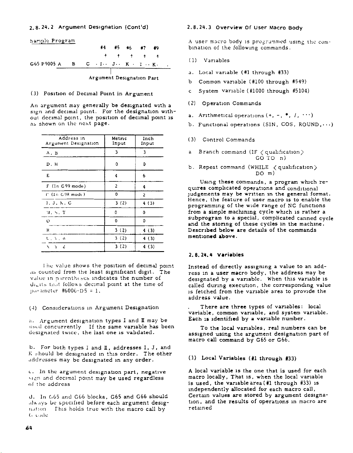
2.8-24.2
Argument
Designation
(Cont'd)
2.8.24.3
Overview
Of
User
Macro
Body
G
(3)
An
sign
out
as
65
Program
P9005
Position
argument
and
decimal
shown
Argument
A,
D.
£
(In
F
(In
F
J
!
.
M.
o
K
,
L
\
A
decimal
point,
on
Address
B
H
G99
98
G
,
K
.
T
S.
\
.
2
'i
B
of
Decimal
may
generally
point.
next
the
in
Designation
mode)
modi
C
C
Argument
the
page.
)
#4
+
•
•
I
•
Point
For
position
#5
#6
+
J
•
K
Designation
in
Argument
be
designated
the
designation
decimal
of
Metric
Input
3
0
4
2
0
(2)
3
0
0
(2)
3
(2)
3
(2)
3
user
A
#7
#9
t
t
t
••
•
I
K
Part
bination
(1)
a.
b
c
with
point
a
with¬
is
(2)
a.
b.
Inch
Input
3
0
6
4
2
4
0
0
4
4
4
(3)
(3)
(3)
(3)
3)
(
a
b.
quires
judgements
Hence,
programming
from
subprogram
and
Described
mentioned
2.8.24.4
macro
of
Variables
Local
variable
Common
System
Operation
Arithmetical
Functional
Control
Branch
Repeat
Using
these
complicated
the
a
simple
the
storing
below
above.
Variables
body
the
following
variable
variable
Commands
operations
operations
Commands
command
command
commands,
may
be
feature
the
of
machining
to
a
special,
of
are
is
programmed
(#1
through
(#100
(
#1000
(IF
(WHILE
operations
written
of
user
wide
these
details
commands.
through
through
(+,
(SIN,
qualification)
<(
GO
TO
m)
DO
a
in
macro
range
cycle
complicated
cycles
of
using
#33)
#549)
#5104)
*.
•••)
/.
ROUND,-
.
COS,
n)
((qualification)
program
and
the
of
which
which
conditional
general
enable
to
is
NC
functions
rather
is
canned
the
in
the
machine.
commands
the
format.
com¬
••)
re¬
the
a
cycle
ts
counted
•
value
dibits
amoter
p.c
(4)
a.
Argument
st_
cl
LI
designated
b.
K
should
addresses
c.
In
sien
the
of
d.
In
.dw.tys,
ii.it
ion
(.
Lode
£4
1
he
value
from
in
nircnlhiics
follows
tnat
#600G-D5
Considerations
concurrently
twice,
For
both
types
be
designated
may
the
argument
and
decimal
address
G65
and
be
specified
This
holds
shows
the
least
decimal
=
in
designation
If
the
I
be
designated
designation
point
blocks,
GG6
before
true
the
position
indicates
1.
Argument
the
last
I,
and
in
may
with
significant
the
at
point
Designation
same
one
I
variable
is
types
addresses
order.
this
in
any
part,
be
used
and
G65
each
argument
the
of
decimal
digit.
number
the
time
U
and
validated.
I,
The
order.
negative
regardless
G66
macro
may
has
J,
should
desig-
call
point
The
of
of
other
by
be
been
and
Instead
ress
of
a
in
user
designated
called
is
address
variable,
Each
assigned
macro
(1)
A
macro
is
fetched
There
is
To
Local
local
used,
during
value.
common
identified
the
using
call
variable
locally,
the
independently
Certain
tion,
values
and
retained
directly
macro
a
by
execution,
the
from
three
are
local
the
command
Variables
That
variable
allocated
are
the
results
assigning
variable.
variable
types
variable,
by
variables,
argument
by
(#1
the
is
is,
stored
body,
variable
a
G65
one
when
area
of
a
the
When
the
corresponding
area
of
variables:
and
real
designation
or
through
that
the
(
#1
through
for
each
argument
by
operations
value
address
this
to
system
number.
numbers
G6b.
#33)
used
is
local
macro
to
variable
provide
variable
#33)
macro
in
add¬
an
may
value
local
variable.
can
part
for
each
is
call,
designa¬
be
is
the
be
of
are
Page 75

Main
Program
Single-level
Macro
Double-level
Macro
Hence,
same
called.
is
macro
nation.
"blank."
at
the
(2)
Common
throuth
common
A
through
and
is,
the
to
the
macro
call
time
#549)
common
results
G65
the
assume
Each
and
The
Each
of
Variables
variable
Common
P9201
A-
••
Argument
Designation
variables
different
local
is
registered
variable
local
power-on
may
macros
all
variable
obtained
Variable
•
B-
variable
not
variable
and
(#100
be
of
enables
by
;
C-
••
#2,
#1,
values
is
by
argument
designated
set
is
reset
through
shared
all
nesting
another
Area
#3,
each
reset
becomes
to
operations.
all
by
levels.
macro
a
macro.
"Read/writÿ
Enabled
Local
for
time
each
for
desig¬
"blank"
#149,
macros
to
09201
'
P9205
C65
A-
#1
••
=
•
#2
=
••
#3
=
variable
single-level
the
it
#500
That
refer
#1.
•
•
•
•
;
#2,
•B-•
a.
are
operations
trols
parameter
#3
•
C-
area
macro
#100
cleared
,
they
b.
#500
are
not
operations.
The
without
user
designated
they
can
G65
P9008
;
•
through
at
and
are
#6008D1
through
cleared
common
by
be
09205
Local
for
#149:
the
time
set
are
not
cleared
is
#549:
the
at
variables
restrictions.
arguments.
designated
;
•
•
A-
;
#1
#2
#3
Read
Enabled
•
#1
#2
#3
•
=
•
•
=
••
=
variable
duplicate-level
These
of
power-on
to
"blank."
by
1.
at
set
These
of
time
are
They
Indirectly,
as
follows.
09008
#100
/write
area
common
In
reset
common
powe-on
available
cannot
#1
=
macro
variables
reset
and
some
operation
variables
and
to
be
however,
con¬
if
reset
the
Single-nest
Macro
Common
two
types
OK
variables
depending
#100
)
#149
OK
Double-nest
Macro
are
divided
on
#500
i
#549
Tripple-nest
clear
OK
Macro
the
into
conditions:
Quadruple-
nest
following
OK
Macro
(3)
system
A
the
to
tem
a.
#1015,
b.
#1115,
System
system.
variables
Interface
#1032T
Interface
#1132+
Variables
variable
:
input
output
Argument
is
the
There
signals
signals
Designation
one
are
following
whose
...
...
#1000
#1100
use
types
through
#1
of
is
of
through
unique
sys¬
65
Page 76

2.8.24.4
Variables
(Cont'd)
YASN
AC
c.
Tool
tool
and
through
#2051
through
through
d.
Alarm
Clock
e.
f.
Single-block
completion
g.
Feed-hold
control
h.
lenturc)
I.
]ÿ
...
RS232C
.
Modal
Positional
#5102
Note:
a.
specifications
tails
and
The
of
The
b.
the
offset
wear
#2150,
#2199,
amount,
amount
#2080,
message
#3001,
...
control
wait
feedrate-override,
#3004
data
information
information
interface
may
not
of
following
variables
#2151
#2201
display
stop
output
be
the
paragraphs
tool
...
#2001
#2081
through
through
#3002
and
auxiliary
...
,
.
.
...
#4001
...
input
installed.
machine
mentioned
coordinate
through
through
#2180,
#2250
...
#3000
#3003
#3100
through
#5001
and
output
tool
describe
above.
#2099,
-function
and
(print
through
Follow
builder.
data.
#2050,
#2101
#2181
exact-stop
out
#4120
signals
the
the
de¬
-o
o
o
o
o
o
o
o.
o
o
-o
o
o
o
o
o
o
o
o
-o
o
o
2C
D
21
D
22
D
23
2"
D
2s
D
26
27
D
2e
D
29
D
0
Q
21
1
21
2
1
2
of
213
21*
1
2
D
D
D
*
D
UI0
UI1
UI2
UI3
UI4
UI5
UI6
UI7
UI8
UI9
UI10
uin
U112
UI13
UI14
UI15
a.
Intervace
#1032)+
When
l.
through
of
side
•
tate
input
the
input
shown
#1007
LT7
27
#1015
15
IT
1
2
an
of
signals
below.
#1006
#1014
5
one
#1015,
operational
each
signals
UI6
26
Ul
4
1
4
1
2
anable
V
V
Input
of
of
is
#1005
#1013
UI1
213
alue
1
0
Signals
the
system
is
specified
expression,
user-macro-dedicated
read.
and
The
the
#1004
UI5
UI4
5
2
3
2“
#1012
UI1
2
212
Input
Contact
Contact
(#1000
variables,
to
relationships
system
#1003
UI3
23
#1011
UI11
211
the
#1002
UI2
22
#1010
UI10
21#
Signal
Closed
Open
Through
right-hand
on
the
16-pomt
variables
#1001
UI1
1
2
#1009
U1
1
9
2
#1000
/off
between
#1000
UI0
#1008
UI18
9
2
#1015,
are
2°
B
as
read
Each
ciated
regardless
When
li.
the
input
of
18
points
decimal
#1032
Sample
IF
2*5
Bit
made
is
#130
2ÿ
Bits
tively
decimal
as
a
Note:
not
be
expressions.
variable
contact
system
signals
positive
=
Program
[
#1015
(UI15)
to
sequence
#1032
=
through
read
System
placed
is
the
of
(16
Z5#
i
=0
EQ
is
to
be
positive
variables
to
is
1.
"closed"
system
unit
variable
(UI0
bits)
through
are
value.
O
read
AND
2ÿ
stored
the
«ÿ
]
GO
and,
number
255
(UI0
value.
left-hand
[lOOO
0
or
or
#1032
collectively
2i
i]
*
TO
if
N100.
through
common
in
#1000
0.0
"open"
of
the
is
UI
100;
is
it
through
side
when
respectively,
machine.
designated,
15)
that
read
"0,"
UI7)
are
variable
of
operational
the
consist
as
branch
a
collec¬
#1032
asso¬
a
#130
can¬
66
Page 77

Interface
b.
#1115,
i.
When
is
#1115
operational
to
sent
output
output
shown
signals.
signals
below:
#1107
U07
7
2
#1115
U15
2is
YASNAC
2°
22
23
2“
25
26
#1132)+
one
specified
expression,
of
each
//1
106
U06
6
2
#1114
U14
u
1
2
Variable
Output
of
system
the
The
and
#1105
U05
2s
#1113
U1
3
21J
Value
1
0
o-
o-
Cb
o-
o-
o-
Signals
{#1100
variables
to
the
left-hand
an
user-macro-dedicated
relationships
the
system
#1104
U04
2"
#1
112
U12
2
1
2
on
#1
103
U03
J
2
#1111
1
U1
2n
Output
Contact
or
variables
#1
U02
#1110
U10
2
Contact
UOO
UOl
U02
U03
U04
U05
UOfe
2
1
off
102
2
0
Through
#1100
side
signal
between
#1
U01
2
#1109
U09
2*
Signal
Closed
Open
through
of
16-point
are
101
1
an
can
the
as
#1100
UOO
2°
#1108
U08
2*
be
When
n.
output
of
16
points
At
this
#1132
in
value.
#1132
With
iii.
value
the
of
them
operational
Considerations
iv.
When
any
stituted
through
"Blank"
Values
"1."
be
Sample
#1107
output
The
contact
the
T/1132
The
output
through
contents
the
output
the
through
(Decimal
system
signals
time,
output
is
=
system
sent
is
written
values
into
#1115,
assumed
is
other
Program
#10
=
(#1132
=
U07)
U03).
240
(UOO
(16
the
#
Z
0
i
=
last
expression,
one
the
than
t
signal
(closed)
signal
are
local
of
signals
11110000
=
variable
through
bits)
are
decimal
in
the
[llOO
variables
retained.
is
the
to
other
of
the
values
be
to
"blank"
=
of
bit
6tate.
AND
bits
of
outputted
variable
of
bits
1.5)
240)
(#10
#1132
collectively
positive
form
2i
i]
*
#1100
right-hand
value
its
1.0
than
system
are
"0."
and
(UG7)
7?
OR
2ÿ
2ÿ
Binary
is
U015)
of
binary
through
Hence,
or
variables,
handled
0
arc
(#8
through
without
are
#8
throuch
15
specified,
that
output.
value
side
is
read.
0.0
assumed
is
outputted
AND
change
outputted
00001111)
=
consist
substituted
16-bit
#1132,
when
of
are
sub¬
#J
as
follows:
151
2ÿ
(1104
2ÿ
(UOO
the
one
an
IOU
to
in
and
to
V
2»
2»
21°
21
21J
2n
2lk
1
2
When
thuuiuh
output
1
5
1.0
in
or
Mil1',
the
o
o
o-
o-
o-
o
o
o
o
0.0
\losed
the
are
usso.
U07
U08
U09
UOIO
UOll
UO
12
U013
UO
14
U015
substituted
luted
or
open'
output
state.
in
any
contact
of
#1100
s
.
c
Tool
Data,
#2001
#2101
#2201
l.
When
through
an
of
amount,
amount
The
ii.
numbers
below
Offset
Wear
Tool
#2050,
-
#2150,
-
#2250
-
one
#2250
operational
tool
can
be
relationships
and
:
Amount
Amount
#2051
#2151
of
the
is
specified
expression,
coordinate
read.
the
system
And
-
-
system
between
Tool
#2080,
#2180,
variable
to
data,
variables
the
the
and
the
Coordinate
#2081
#2181
#2001
right-hand
tool
oL.&el
tool
tool
arc
#2099,
-
#2199,
-
wear
offset
as
side
shown
67
Page 78

2.8.24.4
variables
(Cont'd)
d.
Alarm
Message
Display
(#3000)
in
x
re
X
i/i
x
rt
I
N
IA
«
2
3
TJ
O
rt
—
—
O
OS
H
w
x
re
J
x
10
x
rt
i
N
System
Variable
#2001
to
#2050
#2101
to
#2150
#2201
to
#2250
System
Variable
#2051
to
#2080
#2151
to
#2180
Offset
Tool
Memory
01
to
50
01
to
50
01
to
50
Tool
Coordinate
Memory
51
to
80
51
to
80
No.
No.
macro
#3000
a
program,
this
than
number
When
specified
l.
Using
(less
alarm
control-out
three
be
.
chine
When
u.
"A/B"
or
screen
Its
message
:
tion
Press
The
the
ALM
alarm
bottom
ALARM
condition
to
put
(<alarm
n
=
command,
characters)
32
n
symbols.
digits
this
is
displayed
regardless
can
function
number
CRT
of
to
system
the
and
and
#3000
be
be
machine
message
specify
enclosed
The
not
command
of
the
seen
key.
and
screen.
alarmed
variable
preceded
alarm
one
be
the
on
mode
by
message
occurs
in
>);
the
with
used
is
bottom
and
the
09100
#3000
the
alarm
alarm
by
control-in
number
by
executed,
of
function.
following
displayed
and
0054
N
in
user
a
may
be
state.
message
a
3-digit
should
the
ma¬
"ALM"
CRT
opera¬
and
on
in.
When
specified
expression,
Sample
#116
contents
The
substituted
are
#2081
tool
The
is
erased
are
set.
113
x
re
1
x
x
re
N
one
to
the
its
Programs
#2016
=
#24
=
wear
and
System
Variable
#2081
#2099
#2181
#2199
of
the
left-hand
value
:
of
tool
for
;
amount
the
to
to
above
can
offset
common
(memory
contents
system
side
be
number
variable
of
Tool
Wear
Amount
Memory
81
to
99
81
to
99
of
an
changed.
No.
local
No.
variables
operational
for
16
#116.
81)
of
variable
is
X-axis
X-axis
#24
USERS
550:
When
cause
state
Sample
#3000
MESSAGE
MACRO
RESET
alarm,
of
be
can
Program
=
Message
sample
key
cleared.
(MACRO
550
FLOW)
ERROR.
display
display
pressed
is
message
the
DATA
"ALM”
area
ERROR:
OVERFLOW
and
after
display
DATA
removal
and
of
the
OVER¬
t
the
alarm
68
Page 79

.
Clock
.
When
s
specified,
System
Variable
#3001
#3002
i.
his
.he
Sample
#3001
ii.
The
Type
Clock
Clock
preset
To
system
expression.
Program
=
Restrictions
accuracy
4294968000
iccrus,
The
429496800
occurs,
Sample
Main
G65
setting
accuracy
setting
Program
Program
P9351
(#3001,
system
the
variable
,
0
of
msec
of
sec
T5
1
2
the
has
#3002)
variable
clock
Unit
1
1
The
clock
has
the
clock
the
,
ms
s
clock,
put
been
clock
been
clock
#3001
can
be
At
Power-On
Reset
Same
power-off
time
substitute
the
at
clock
8
is
1
reached,
to
8
is
2
reached,
to
Argument
variable
of
•
•
Macro
3
read.
to
as
left-hand
is
preset
ms.
"0,"
ms.
"0."
seconds
or
#3002
Condition
"0"
Always
When
signal
the
When
and
When
overflow
an
designation
#20
to
wait
Count
value
to
value
overflow
for
side
for
STL
is
clock
on
with
of
"0."
When
distribution
this
In
with
the
not
is
FIN
next
the
#3003
Feed-Hold,
g*
tioning
When
the
substituted
feedrate
can
be
#3004
0
1
2
3
4
5
6
7
Sample
finish
the
end
case,
Completion
made
check
waited
auxiliary
0
1
2
3
value
in
override,
Feed
Valid
Invalid
Valid
Invalid
V
alid
Invalid
Valid
Invalid
Program
the
Block
system
valid
Hold
(DEN)
waited
is
careful
be
.
in
the
variable
positioning
invalid.
Feedrate
Override
Valid
Valid
Invalid
Invalid
V
alid
V
alid
Invalid
Invalid
is
signal
signal
FIN
cleared.
skip
for,
function.
Single
Switch
Valid
Invalid
Valid
Invalid
Feedrate-Override,
Control
listed
and
or
not
waited
is
not
for
Hence,
not
FIN
Waited
Waited
Not
Not
(#3004)
following
#3004,
Vosilioning
Completion
for,
transmitted.
in
the
when
to
specify
Signal
mod
*
waited
And
Posi¬
table
feed
completion
Valid
Valid
V
alid
Valid
alid
ln\
Invalid
Invalid
In
valid
the
block
the
is
hold,
09351
#3002
WHILE
END
M99
Single
Program
=
1
,
the
Macro
f.
Completion
When
substituted
switch
block
may
be
of
tion
the
finish
(MST)
;
;
0
[#3002
,
Block
Wait
value
in
entered
.
GE
Stop
Control
listed
system
can
without
signal
#1
be
[
D01
And
(#3003)
the
in
variable
disabled
waiting
(FIN)
,
Auxiliary
following
#3003,
or
of
the
Function
next
the
the
for
auxiliary
table
the
block
checking
is
single
func¬
Special
Command)
Macro
G65
Threadcutting
+X
r
i
-1-
L
~*i'\
HK(-
O
Call
P9093
U--
Cycle
(Incremental
G5<3
THREAD-
i
P-
I'UTTtfiC
I
K
—
w-
•
W
K-
•
F-
----
:
#6
—
#23:
—
#21:
—
Negative
value
Negative
value,
;
•
#9:
Without
radius
U-/2
I
+z
Lead
sign
value
value
diameter
,
69
Page 80
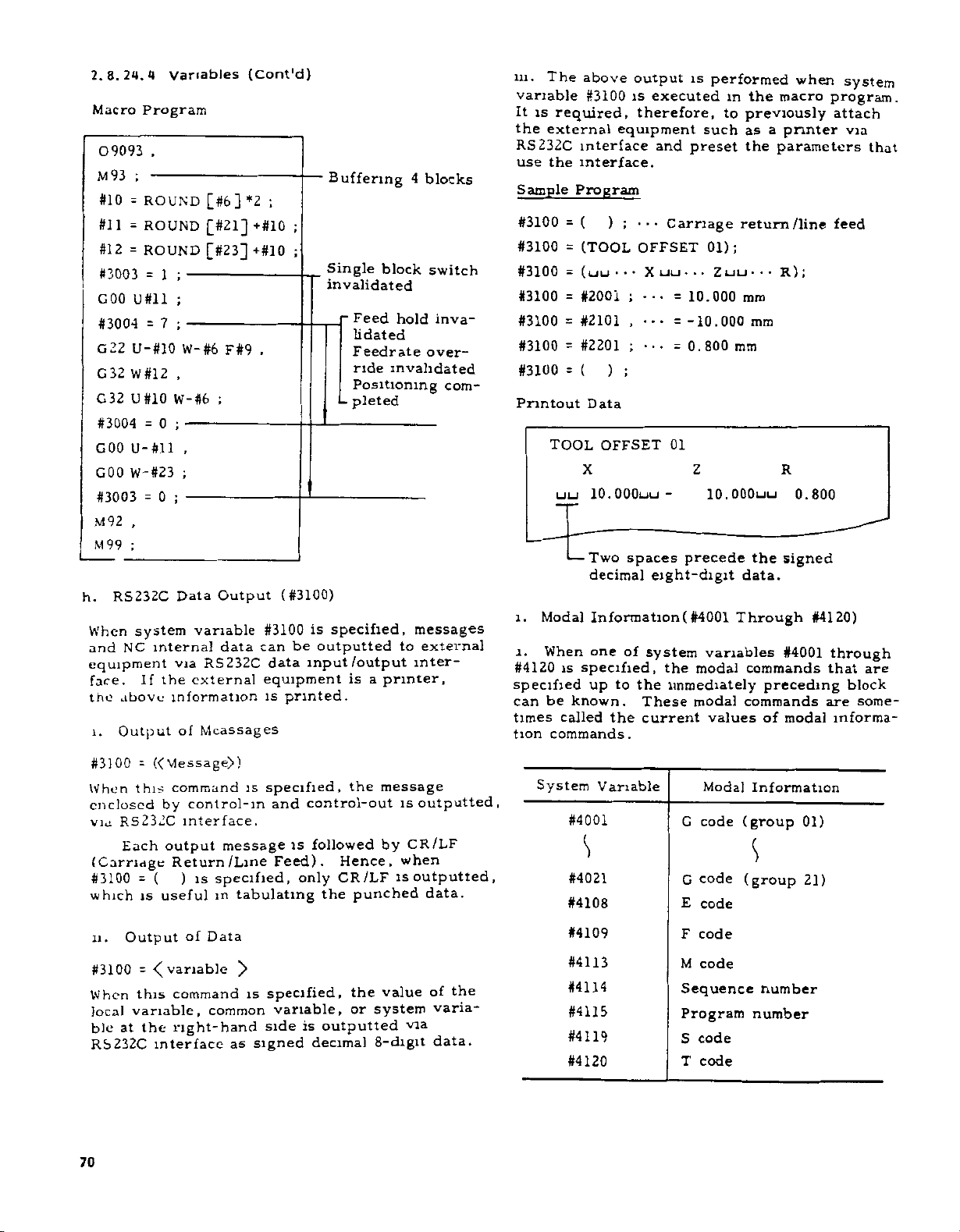
2.8.24.4
Macro
09093
M93
#10
#11
#12
#3003
GOO
#3004
G22
32
C
G
32
#3004
GOO
GOO
#3003
M
92
M
99
RS232C
h.
When
NC
and
equipment
face.
above
the
Output
i
.
Program
.
;
-
ROUND
=
ROUND
=
ROUND
=
=
U#ll
=
U-#10
W
#12
U#10
=
U-#ll
W-#23
=
,
;
system
interna!
If
variables
[#6]
[#21]
[#23]
;
1
-
;
;
7
-
W-#6
,
W-
#6
0
;
-
,
;
;
0
-
Data
variable
RS232C
via
external
the
information
Mcassages
of
F#9
;
Output
data
{Cont'd)
;
*2
+#10
+#10
,
(#3100)
#3100
can
data
equipment
is
Buffering
;
;
Single
invalidated
specified,
is
outputted
be
input/output
printed.
block
rFeed
lidated
Feedrate
ride
Positioning
pleted
-
is
a
printer,
4
blocks
switch
hold
inva¬
over¬
invalidated
com-
messages
to
external
inter¬
in.
The
above
variable
It
is
the
RS232C
use
Sample
#3100
#3100
#3100
required,
external
interface
the
interface.
Program
(
=
(TOOL
=
(
=
#3100
LJ
#3100=#2001
#3100=#2101
#3100
#3100
Printout
l.
l.
#4120
specified
can
times
tion
#2201
=
(
=
Data
TOOL
X
uu
10.
Two
—
decimal
Modal
When
is
be
called
Information
one
specified,
up
known.
commands.
output
is
therefore,
equipment
)
;
OFFSET
*
*
*
LJ
;
,
;
)
;
OFFSET
OQOuu
spaces
of
to
the
These
current
the
executed
and
preset
Carriage
uu
•
X
•
10.000
••
=
-10.000
=
•
•
0.
=
01
-
precede
eight-digit
(
#4001
system
the
immediately
is
performed
in
to
such
01);
ZLJLJ
••
800
z
lO.OOOuu
variables
modal
modal
values
macro
the
previously
a
as
printer
the
parameters
return/line
••
•
R
ram
mm
ram
R
the
signed
data.
Through
#4001
commands
preceding
commands
of
modal
when
)
;
0.800
#4120)
system
program.
attach
via
feed
through
are
that
block
are
some¬
informa¬
that
#3100
When
enclosed
via
(Carriage
#3100
which
.
n
#3100
When
local
ble
RS232C
70
«Viessage>)
=
this
by
RS232C
Each
( )
-
useful
is
Output
=
this
variable,
the
at
interface
command
control-in
interface.
output
Return
is
of
Data
command
common
right-hand
is
message
/Line
specified,
in
tabulating
}>
is
as
signed
specified,
control-out
and
followed
is
Feed).
only
specified,
variable,
side
is
decimal
the
Hence,
CR/LF
punched
the
the
or
outputted
message
is
CR/LF
by
when
is
value
system
via
8-digit
outputted,
outputted,
data.
of
the
varia¬
data.
System
Variable
#4001
S
#4021
#4108
#4109
#4113
#4114
#4115
#4119
#4120
Modal
G
code
code
G
E
code
F
code
M
code
Sequence
Program
S
code
T
code
Information
(group
(group
number
number
01)
21)
Page 81

ii
#4001
left-hand
Sample
Main
Program
G65
Macro
09602
#1
=
GOO
G01
G03
GOO
G
#1
99
M
through
side
Program
P9602
Program
;
#4001
X
2-
••
X-
•
•
2
•
.
-
,
to
the
System
Variable
#5061
#5062
#5081
Positional
X-axis
position
2-axis
position
X-axis
Information
skip
(ABSKP)
skip
(ABSKP)
tool
offset
signal
signal
Read
Enabled
Enabled
During
Move
(
Note)
of
#4120
the
cannot
operation
Designationÿ
placed
be
expression.
;
amount
offset
#5082
Z-axis
tool
amount
(
position
#5101
X-axis
deflection
;
•
•
Y
•
•
F
2
;
,
•
•
R
•
•
•
•
codes
G
G03)
retained
G
codes
are
(GOO
of
01
.
of
restored.
through
group
01
group
are
#5102
Note:
#5101,
ment,
will
movement.
Mnemonic
Reading
#5102,
and
be
ABSIO
Z-axis
deflection
servo
servo
#5021,
of
when
performed
amount
amount
commanded
after
ABSMT
position
#5022,
#5041,
during
completion
ABSOT
Enabled
#5042,
of
ABSKP
Note)
move¬
the
j.
Positional
When
specified,
obtained
The
unit
es
Metric
Inch
the
In
feature
System
Variable
system
.
of
user
is
#5001
#5002
#5021
#5022
#5041
#5042
Information
variables
various
the
input
input
macro
invalid.
Positional
X-axis
position
Z-axis
position
X-axis
position
Z-axis
position
X-axis
position
Z-axis
position
#5001
positional
information
0.001
0.
body,
Information
block
(ABSIO)
block
(ABSIO)
current
(ABSMT)
current
(ABSMT)
current
(ABSOT)
current
(ABSOT)
(#5001
0001
the
end
end
Through
through
information
millimeters
is
Unit
millimeter
inch
"input
#5102
unit
Read
Move
Enabled
Enabled
Enabled
#5102)
can
or
x
During
(Note)
(Note)
are
10"
be
mch-
Meaning
Coordi¬
nate
system
Tool
position
Oflset
Tool
radius
compen¬
sation
Amount
Notes
When
1.
block,
G31
block.
2.
The
macro
the
by
part
macro
3.
System
be
placed
expression.
:
the
body.
End
sition
block
mediately
before.
Work
coordi¬
nate
system
Not
included
Not
included
the
skip
"input
call
G65
to
po¬
skip
signal
unit
block
C66)
or
variables
the
Command
of
current
im¬
position
(same
as
POS.
MACHINBVERSAL
display)
Machine
coordi¬
.
nate
system
not
x
(the
but
#5001
is
position
10"
argument
is
feature
invalid
through
side
signal
left-hand
Command
current
position
(same
UN
POS.
display)
co¬
Work
ordinate
system
Included
Included
turned
is
at
is
designation
in
o:
operational
as
I-
.
the
valid
the
#5102
Position
which
at
skip
did
nal
not
go
in
C31
block.
Work
ordinate
system
Included
Included
on
in
end
up
user
ma>
sig¬
on
co¬
C31
of
to
not
71
Page 82

2.8.24.4
Sample
The
(X,
forms
start
Main
G65
Macro
:
C
'603
#1
c2
91
G
COO
COO
M
#
GOO
c.UO
Variables
Program
is
tool
Y,
Z)
the
positioned
on
machine
specified
point.
Program
X
9603
P
Program
,
,
#3001
=
=
1
#5002
,
X
Z
3
7
X#1
,
#502
#24-
[
[#26-#5022]
.
,
#2
,
#24
(Cont'd)
M
;
1
]
;
to
the
coordinate
feature,
U...
#26
specified
and
;
#13
system,
returns
location
per¬
of
List
Variable
No
#1
to
#33
Local
variables
to
to
#100
#149
#500
#549
#1000
#1015
#1032
#1100
#1115
#1132
#2001
to
to
to
to
Common
power-off)
Common
off)
.
Interface
for
each
Interface
Interface
for
each
Interface
Variables
variables
.
variables
input
bit)
.
input
output
bit)
.
output
Moaning
(reset
(retained
signals
signal
signals
signal
(each
15
{£
i=0
(each
15
(I
i=0
to"blank"
power-
at
signal
[lQOO
#
*
signal
#
00
1
fl
*
2i).
2i)
at
+
lÿ
+
i"l
#2050
to
#2101
#2150
#2201
to
Tool
(X-axis,
offset
amount
Z-axis,
nose
radius)
#2250
to
#2051
#2080
#2151
Tool
coordinate
(X-axis,
to
Z-axis)
data
#2180
to
#2081
#2099
#2181
to
Tool
(X-axis,
wear
amount
Z-axis)
#2199
#3000
#3001
#3002
#3003
#3004
#3100
#4001
#4120
#5001
#5002
#5021
#5022
#5041
#5042
#5061
#5062
#5081
#5082
#5101
#5102
to
to
to
to
to
to
to
Alarm
Clock
Clock
Single
complete
Feed-hold,
act-stop
RS232C
Current
command.
End
position
preceding
Current
system
Current
(for
each
Position
turned
Effective
amount
Servo
axis)
each
message
(in
1
units
(in
2
units
block
wait
feedrate-override,
control
data
value
block
position
(for
each
position
axis)
at
which
(for
on
tool
(X-axis,
position
display.
stop,
control.
output
of
of
the
(for
of
of
.
each
position
Z-axis)
deflection
of
1
Is).
of
auxiliary
(print
modal
immediate
each
machine
axis)
POS
skip
C31
axis)
ms)
function
out
information
axis).
coordinate
.
UNIVERSAL
signal
.
offset
amount
and
feature).
is
(for
ex¬
72
Page 83

(4)
Variable
Each
that
a.
How
(i
#i
Sample
How
b.
number:
[
<expression
#
Sample
the
In
replaced
variable
follows
to
1,
=
to
following
with
Representation
is
represented
#.
designate
2,
3,
4.
#10
#130
#2000
designate
>)
[#100]
#
T#50Q
#
#
[#20/2]
description,
variable
Sample
(i)
a
in
variable
a
number
..)
.
an
expression
+
l]
#[<
directly:
as
variable
expression
a
#i
>].
number
variable
may
be
When
...
X#1
(ii)
...
F#2
(ui)
P
G04
(IV)
...
M
#4
...
G#4
Value
4.
maximum
the
5.
The
replaced
The
6.
brackets
in
point
When
=
When
#3
When
at
=
...
M03
G03
value
with
constant
its
45.2346
#1
=
X45.235
0.255
#2
=
F0.26
5.
#3
=
G04
=
2.
#4
=
each
for
programmable
that
Expression
[
1
end.
mm
(mm/rev)
37672
P5.
7236
address
follows
without
is
assumed
(for
377
metric
(see)
should
value.
address
an
>.
decimal
to
point
have
input)
not
exceed
may
enclosed
decimal
a
be
(5)
Variable
The
<
value
value
by
address
a.
replaced
When
the
(complement,
the
value
Sample
Sample
of
above
The
specification
G
X100.
01
:
Notes
1.
Address
bles.
2.
variable
A
a
variable.
Sample
Reference
that
variable.
a
>
the
of
variable
more
address.
#30
#101
#103
#140
G#30
specification
below
Z-300.
1,0,
/#8,
number
##20
#[
#20]
follows
or
#i
exactly)
1.
=
100.
=
300.
=
0.
=
X#101
.
and
N
#100
.
..
...
an
(address
or
;
0
;
,
3
i
Z-#102
equivalent
is
F0.
3
N
may
...
may
Error
Correct
address
its
is
;
not
Error.
not
.
>
negative
made
F
#140
refer
be
.
may
is
-ft
the
;
to
replaced
be
specified,
value
specified
the
varia-
to
with
(6)
Undefined
value
The
be
"blank."
following
a.
The
nation
Common
b.
of
time
c.
The
which
for
panel
.
of
situations:
local
not
was
power-on
local
the
Variable
an
undefined
An
undefined
variable
performed
variables
and
variables
values
for
#100
reset
and
were
variable
variable
which
macro
in
through
operations.
common
not
argument
written
is
assumed
occurs
command.
call
#149
variables
from
at
the
in
desig¬
the
MD1
to
3.
values
ed.
When
a
below
variable
the
least
used
is
significant
as
address
digit
data,
are
the
round¬
73
Page 84

2.8.24.4
Designation
the
in
control
versions
changed.
Concept
1
#0.
2
Variable
iscommanded
the
jin
Iment
I
(Variable
3
iscommanded
the
m
(program.
[Variable
4
commanded
is
j
the
in
tion
!NE.
1
'
t
(Others
5
Variable
and
following
set
is
to
A
of
(Cont'd)
(unction
two
cither
for
and
B
•No
of
•Commanding
#0
<blank>
replace-
equation
'Where
<blank>,
'mand
.
means
!
:
.
<blank>!*Where
ana
;<blank>,
mand
I
to
GOO
'Where
j
j
j
i(2)
"IF
not
“Condition
•Condition
is
<blank>,
#3
1)
"IF
established
#3
#3=#2
#3=#0+#0
#3
#3
#3=2-
#3=5/
<Blank>
described
n0.
lished
<blank>,
<blank>.
established
are
and
condi-
of
part
<blank-
EQ
of
versions
version.
from
Version
conception
#0.
causes
#2
#3
#3
#2
600
equivalent
command
x
0;
#2
0.
is
Condition
#3EQ#2"
Condition
NE#2"
#3
established
[
#
=
#0
=
5
=
*
"
when
<blank>,
#3
<blank>
A
to
B
A
alarm.
is
com-
#2;
=
0.
=
is
com-
x
#2;
is
.
#0+#0
#0
*
/
#0
#0
#0
#0
in
the
above
IF
or
IF#3
0.
=
is
B.
and
Switching
cannot
A
Version
defined
•#0
variables
<blank>.
•Commanding
at
#0
hand
equation.
•Where
|<blank>,
mand
means
#3
•Where
<blank>,
mand
is
equivalent
to
command
GOO;
ignored.
is
<blank>,
is
#3
(I)
Condition
is
"IF
#3EQ#2”
established
(2)
Condition
]
is
"IF
#3EQ#2''
established.
.|
]
;
;
;
;
;
;
#2
#2
when
means
causes
replacement
is
GE#2
#3
and
0
is
#2
LT
#2
or
#2
In
commands
#3
is
classified
The
be
the
left-
sideofthe
#2
#3
=
<blank>.
=
#2
600
(Address
#2
0.
these
0.
=
#3
=
alarm.
treated
estab¬
is
are
#3
and
#3
not
is
and
<blank>,
from
inter¬
B
of
is
com-
#2;
is
com¬
x
#2;
is
2
is
#3
2.8.24.5
Various
variables
The
form
a
is
duced
operators
tions
#}
as
)
is
.
is
,
as
and
(1)
#i
=
(2)
#i
=
#i
=
#i
=
#i
=
(3)
#i
=
#i
=
#i
=
Note
variable
the
is
performed
(4)
#i
=
#1
=
#i
=
#1
=
#1
=
#1
=
#1
=
-
#1
#1
=
#i
=
#1
=
Operation
operations
and
operation
of
#1
<expression>
by
combining
and
and
functions
,
#k
•••
#k
#k
-
OR
XOR
#]
#k
*
#k
#)
/
#j
AND
•
OR,
In
value
Functions
SIN
[#)]
COS
[#j
TAN
[#}]
ATAN
SQRT
ABS
[
[#)
BIN
BCD
[
ROUND
FIX
[#)
FUP
[#)]
=
arithmetic
constants
Difinition
definition,
#k
#k
#k
32-bit
]
#j/#k]
[
[#]]
#j
#)]
[#]]
]
general
Variable
#)
Add-Type
#}
#j
#j
#j
Multiply-Type
binary
can
between
expression
functions.
Operations
•
•
Sum
Difference.
•
•
•
Logical
32
•
•
Exclusive
(for
Operations
•
••
•
•
Quotient
••
•
XOR,
constant)
(or
equivalent
on
each
]
•ÿ
]
••
Commands
be
variables
is
operational
variables
are
as
may
be
and
replacement.
.
bits)
each
Product
Logical
(for
each
or
AND
bit.
Sine
Cosine
Tangent
Arctangent
Square
Absolute
Convert
Convert
Produce
Truncate
Raise
performed
and
represented
tn
which
.
and
The
available
follows.
used.
Replacement
(for
sum
.
logical
of
32
.
.
product
32
of
operation,
converted
is
and
(in
degrees)
(in
degrees).
(in
root.
value.
from
into
integer
the
the
fractions
between
constants.
expression
constants
Instead
each
sum
bits).
bits).
operation
the
degrees).
(in
degrees)
BCD.
BCD.
fractions.
in
opeara-
of
the
.
by
roundini
to
into
the
of
a
pro
with
.
unit
74
Page 85
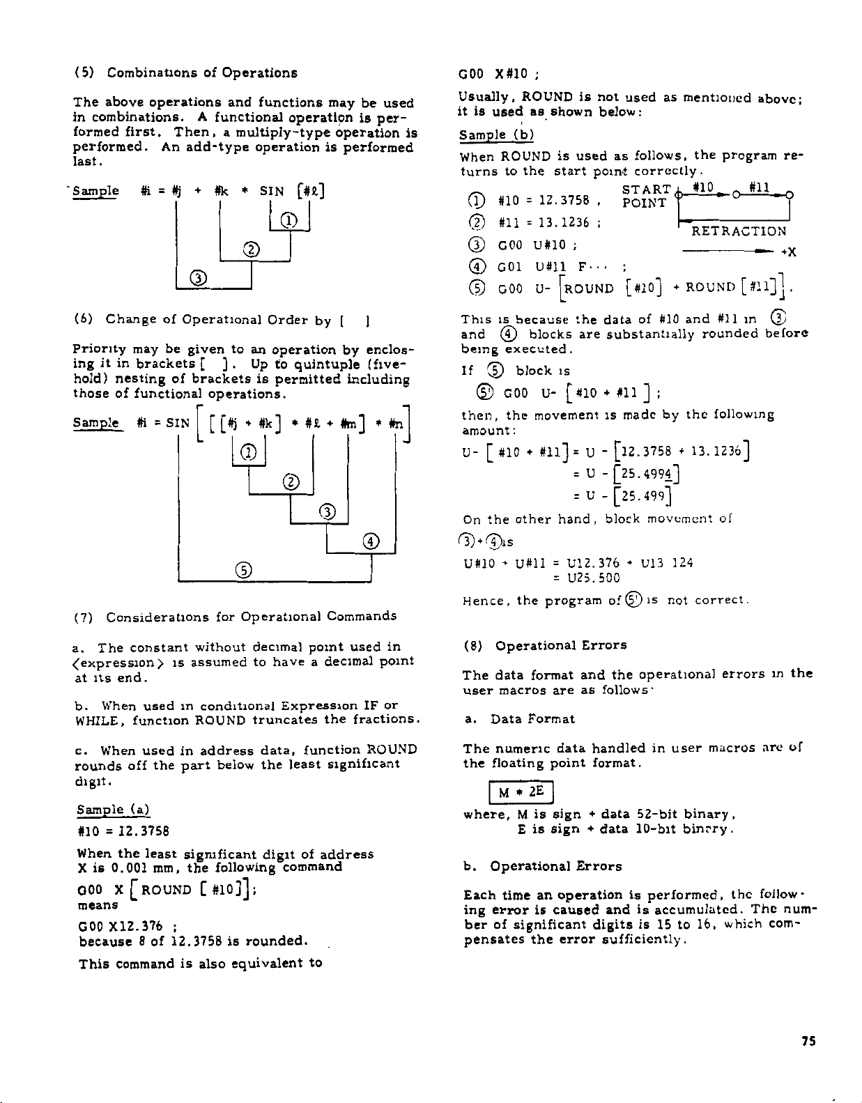
(5)
Combinations
The
above
in
combinations.
formed
performed.
.
last
'
Sample
first.
ft
operations
Then,
An
add-type
+
#j
=
©
of
Operations
and
A
functional
a
#k
functions
operation
multiply-type
operation
SIN
*
[#*]
©
CD
may
operation
is
performed
is
be
used
per¬
X#10
ROUND
used
(b)
ROUND
the
to
#10
#11
GOO
G01
GOO
;
is
not
as
shown
start
12.3758
=
13.1236
=
U#10
U#ll
U-
is
below:
used
point
,
;
;
F---
|ROUND
used
follows,
as
correctly.
START
POINT
;
[#10]
as
mentioned
the
#10
x
RETRACTION
+
ROUND
program
jin
r
0
[#ll]j
above;
re¬
.
,
GOO
Usually,
is
it
is
Sample
When
turns
(l)
(?)
(3)
©
©
(6)
Change
Priority
it
ing
hold)
those
Sample
(7)
Considerations
The
a.
its
at
When
b.
WHILE,
may
in
brackets
nesting
of
functional
ft
constant
end.
used
function
=
>
of
be
of
SIN
is
Operational
]
[
brackets
operations.
[#j
[
for
without
assumed
conditional
ROUND
to
.
given
in
Order
an
operation
Up
to
is
permitted
4
#k]
©
©
©
Operational
decimal
to
have
Expression
truncates
by
quintuple
4
#£
*
©
Commands
point
a
decimal
the
[
)
enclos¬
by
(five-
including
#m]
*
©
used
IF
fractions.
#n
in
point
or
This
is
and
being
If
©
©
then,
amount
U-
[#10
the
On
©ÿ©is
U#10
Hence
(8)
Operational
data
The
user
a.
Data
because
blocks
©
executed
block
GOO
the
:
other
U#ll
-
,
the
format
macros
Format
the
are
.
is
U-
#10+#11
[
movement
#ll]
=
=
=
hand,
U12.376
=
U25.500
=
program
and
as
are
data
substantially
made
is
U
[12.3758
-
U
-
[25.4994]
U
-
[25.499]
block
4
of
©
Errors
the
follows’
#10
of
]
U13
operational
and
;
the
by
4
movement
124
is
not
13.1236]
#11
rounded
following
of
correct.
errors
in
©
before
in
the
When
c.
rounds
digit.
Sample
#10
When
is
X
Q00
means
GOO
because
This
used
off
the
(a)
12.3758
=
the
least
mm,
0.001
X
[ROUND
X12.376
8
12.3758
of
command
address
in
part
significant
the
[
;
is
also
below
following
;
#10]]
rounded.
is
equivalent
data,
the
digit
command
function
least
of
significant
address
to
ROUND
numeric
The
the
floating
M
where,
Operational
b.
Each
time
ing
error
of
ber
pensates
data
point
2E
*
sign
is
M
is
E
sign
operation
an
caused
is
significant
error
the
handled
format.
+
data
+
data
Errors
and
digits
sufficiently
in
52-bit
10-bit
is
performed,
is
accumulated.
is
15
user
binary.
binrry.
to
.
macros
16,
the
which
are
follow¬
The
com¬
of
num¬
75
Page 86

2.8.24.6
commands
The
micro-program
a.
Branch
ssionÿ
h.
Repeat
expression
(1)
Branch
a.
If
established,
sequence
When
the
condition
to
[
IF
conditional
<
a
branch
next
the
Control
TO
GO
Command
>}
<
conditional
number
variable
destination
is
Commands
which
of
are
command
;
n
m
DO
Command
expressiorÿof
a
branch
n
or
satisfied,
not
block.
control
the
...
...
,
expression
within
an
following
IF
WHILE
is
made
the
expression
may
the
the
[<
conditional
this
to
same
be
changed.
program
flow
two
(
<
conditional
>)
GO
command
the
block
program.
is
used
of
the
types:
TO
proceeds
expre¬
is
of
for
If
n
the
Conditional
and
LE.
Conditional
;
n,
A
constant
and
used
Notes:
1.
head
branch
the
#]
for
The
of
sequence
They
#1
#1
#i
fc
#i
*i
.
A
n.
sequence
the
command.
expressions
Expression
£Q
NE
GT
LT
CE
#)
LE
<
and
variable
block
number
are
#)
#]
#)
#)
#j
expression>
number
when
are
represented
and
<expression
it
Otherwise,
is
ignored
must
is
KQ
tti
(#i
(#i
Uh
(#1
Oh
may
called
the
,
NE,
as
Meaning
*
>
<
2
S
be
located
be
for
data
as
Gl',
follows:
fO
#))
#))
#j)
#))
»))
used
may
>
by
shown
prior
LT.
for
be
at
the
a
to
below:
CE,
#i
3
DJ
IF
provide
:
Jlr
i
z
a
:
I
1
!“•
—
S
u
03
jy
CL
C-Nn
£
tn
IF
—
simple
GO
Conditional
expression
(Next
expression
branch
TO
Block)
,
n
GO
may
command
TO
as
n,
be
omitted
shown
to
below:
2.
longer
(2)
a.
(m
While
blocks
When
to
the
<
The
execution
Repeat
WHILE
,
1
=
END
between
it
block
Branch
,
reverse
[
2
and
m
unsatisfied,
is
Destination
G01
X10
branch
time
Command
<
conditional
3)
;
DO
following
Sequence
35
N
Z
Executed
this
on
than
expression
expression)
and
m
the
END
END
processing
in.
25
the
the
FO
data
m
No
25
with
ignored
program
forward
satisfied,
is
are
.
branch.
>]
DO
repeated
branches
takes
;
m
the
.
76
T3
V
Jr~
-5
•S
—
4)
w
c
D
WHILE
.
•—
END
“(Block
{ÿConditional
expression>J
m,
-
m)
following
END
;
DO
m
—
—
o>
x
Page 87

When
[_<
conditional
m
DO
erally,
specification
the
END
and
this
I
jh
•c
si
u
U
3
-
£
J
--
t-
D
-
O
.0
So
8
=
expression
m
used
is
m
PO
IF
tn
ESP
made
is
>]
repeated
are
in
the
.
expression)ÿ
CO
,
the
format
TO
omitting
blocks
infinitely.
shown
,
n
WHILE
between
Gen¬
below.
a.
x
5.
micro
Triple
program.
DO
DO
DO
C65-
END
END
END
DO-Ioop
1
.
2
.
3
.
•
ABC
3
.
,
2
1
.
.
nesting
DO
DO
DO
G65'
END
END
END
permitted
is
)
.
2,
,
3
•
XYZ
,
3
2
.
,
1
for
each
,
:
Notes
DO
1.
2.
of
m
value.
m.
in
3.
The
repeatedly
4.
To
used.
entrance
—
—
m
should
m
DO
However,
DO
1
END
1
2
DO
—
2
END
same
except
get
out
However,
to
a
Nn
specified
be
and
END
only
The
called
is
number,
DO
and
other
-
identification
where
of
DO
a
a
GO
DO
loop
m
should
2,
1,
value
the
whichisused
END
repeat
loop
TO
n
as
shown
before
or
3
m,
1,
of
identification
call
to
number
ranges
,
a
GO
does
below:
have
may
2,
each
TO
not
END
or
may
the
be
3
by
be
overlap.
n
enable
m.
same
specified
used
can
be
6.
(i)
(n)
(m)
The
Enabled
codings
DO
1
DO
1.
END
DO
1
END
END
DO
1
DO
END
shown
,
;
1
-
.
)
,
-
1
.
,
Overlap
ranges
9
2
permitted.
.
Rewrite
shown
—
1
The
of
One
END
is
as
right
Enabled
below
return
1
END
DO
of
not
cause
destination
is
unknown
is
1
missing
DO
DO
END
END
1
2
,
,
1
2
1
error:
an
.
,
,
DO
1
Ip-COTO
x>
go
“L.N100
END
100
,
1
;
2
.
-ÿGOTO
:
|i
DO
SU-NIOO
END
°
,
100
,
1
,
]
,
END
-
77
Page 88

2.8.24.6
<l\)
)
(\
DO
DO
DO
DO
END
END
END
END
DO
7000
N
END
Control
1
.
:
.
3
.
1
.
1
3
2
1
1
.
1
nesting
triple
(Cont'd)
nesting.
permit¬
Commands
Quadruple
Max
is
,
-
ted
(2)
Classification
program
The
follow
Piogram
OJ
08000
08990
ll'C
to
No
07404
to
of
numbers
riip.-i
erased,
ed
.
restrictions
When
registration,
programs
Program
are
Classilication
piogi
D4
of
are
classified
ini.-.
m.iy
ui
edited
is
*6004
erase,
disabled
Numbers
be
icgistcr-
without
to
set
edit
and
into
1,
the
the
of
.
is
erase,
disabled
Of
#33)
#500
set
and
by
to
edit
Local
and
through
the
the
1.
of
And
common
following
Com¬
var
#549)
#6021
D7
(#1
And
through
and
of
are
Write
#149,
written
Display
through
When
registration,
programs
9000
to
.
,
may
loop
DO
be
entered
outside
not
from
0
09999
2.
8.
24.
mon
Variables
Local
lables
can
be
operations
8
variables
(#100
displayed
IF
2.8.24.7
(1)
How
The
registration
(macro
manner
Hence,
anphes
programs)
as
there
to
subprograms,
together
capacity
.
1
GO
O
7000
Registration
to
Make
usual
is
the
user
and
the
in
part
,
—
of
Registration
and
edit
are
performed
part
programs
program
no
macro
macro
program
1
User
of
body.
programs
Macros
of
user
size
memory
User
macro
in
the
and
subprograms.
restriction
Part
may
Macros
bodies
same
programs,
be
stored
to
its
that
full
(1)
Display
Press
be
Key-in
of
provided
Display
a.
may
b.
CURSOR
not
need
bers
including
their
data
the
in
fraction
L
signed
SETTING
LEVEL
#0100
#0101
#0102
#0109
Operations
Variables
SET
the
key
be
keyed
are
part.
Macro
(0
0
function
anywhere.
variable
or
CURSOR
in.
the
specified
displayed.
8-digit
nesting
not
Macro
MACRO
-12345678
key.
number
t
Ten
integer
level
execution)
in
0
3
Mode
key.
sets
variable
The
data
part
01234
12345678
00000001
00000000
N
and
of
and
0033
select
press
However,
variable
number
are
displayec
the
positioi
#
num¬
and
8-digit
78
Sample
Display
of
Common
RDY
Variables
Page 89

c.
Press
display
may
PAGE
+
be
key
scrolled
or
PAGE
up
or
T
key,
down.
and
the
2.8.24.9
User
(1)
Summary
Considerations
Macros
of
Restrictions
And
Remarks
For
Remarks
Common
a.
for
review.
b.
For
rently
when
local
the
other
variables
to
rest
(2)
Write
Writing
Press
a.
may
be
b.
Key-m
press
ever,
variable
positioned
c.
Key-m
key.
of
the
ed.
d.
Press
f
PAGE
e.
Repeat
values
local
executed
a
macro
variables
nesting
after
"blank."
Operations
of
Values
SET
provided
CURSOR
need
#
number
to
keyed-in
The
variable
key
to
the
variables
variables,
are
of
a
nesting
belonging
levels
completion
to
function
anywhere.
the
variable
not
it.
value
key
be
is
number
i
the
CURSOR
PAGE
or
-
operations
desired
may
those
displayed.
cannot
Variables
key.
number
or
keyed-in.
specified
to
be
value
with
key
key
in
variables.
always
of
level
to
seen.
be
of
execution
Mode
T
CURSOR
and
written.
stored
is
the
or
CURSOR
to
move
c.
and
be
displayed
macro
the
Consequently,
execution,
is
in
macros
of
The
are
select
be
to
written
key.
keyed-in
The
cursor
the
Press
the
as
cursor
i
d.
to
the
position¬
key
cursor.
write
cur¬
the
local
all
position
How-
is
WR
data
or
the
Available
a.
through
#1
through
#100
through
#500
System
b.
Available
Maximum
Minimum
Constant
c.
1(8
digits
decimal
Sample
Operational
d.
Decimal
Macro
e.
Quadruple
Maximum
f.
Triple
Repeat
g-
1,
m
=
#33
variables
value
value
above
points)
Maximum
Minimum
digits
15
Call
(four-hold)
(three-
Command
2,
and
Variables
•••
#149
T
#549
Variable
•••
•••
Values
decimal
.
value
value
Accuracy
significant.
Maximum
Nesting
hold)
3.
variables.
Local
Common
variables.
Values
±10+3°8
308
ilO"
<
Expression
Usable
in
point).
(7
199999999.9999999
10.0000001
Nesting
Level
.
Repeat
(DO)
of
each
Identifier
macro.
Level
for
digits
Command
m
>
below
Remarks
a.
Common
b.
Local
time
other
Any
attempt
rewriting
tion
may
attempting
ation
by
is
it
safe
c.
The
ables
the
reset
written
#100
variables
variables
than
to
of
local
cause
the
single
to
rewrite
through
operation
may
when
so
do
variables
an
unexpected
rewriting,
stop
1
variables.
local
#149
or
can
always
not
a
macro
is
invalidated.
stop
unction
variables
are
the
power-on
be
written
is
during
failure.
the
and
and
reset
be
in
macro
machine
check
to
changed.
at
execution.
However,
Before
to
common
"blank"
operation.
any
execu¬
oper¬
see
vari¬
by
h.
Maximum
Quintuple
(2)
Difference
Nesting
(five-hold).
between
Level
User
of
Macro
Brackets
and
Sub¬
program
argument
allow
G66
and
but
body
M98
G65
the
macro
without
with
of
the
block.
subprogram
directly
executing
G65
in
macro.
the
a
branch
command
or
(M98)
branches
block
G66
With
performed
is
(if
any)
any
docs
the
to
command
and
sub¬
the
other
not.
has
after
than
macros
User
a.
designation
it
b.
user
that
no
program,
the
P
and
user
The
macro
was
specified
relationship
execution
L
however,
in
79
Page 90

2.8.24.9
User
Macros
The
c.
quadruple
subprograms
d.
If
user
automatic
is
restricted
to
up
four
mode
or
(3)
Relationship
a.
MDI
execution
b.
MDI
body
commands
control
commands.
Considerations
(Cont'd)
maximum
including
is
also
macros
operation,
to
quardruple.
levels
the
mode,
permits
called
does
such
memory
writing
of
writing
nesting
are
of
with
And
G65
and
quadruple
specified
the
maximum
nesting
or
MDI
the
macro.
not
permit
as
operational
Remarks
level
of
G66
but
With
are
separately
Operation
macro
For
user
calls.
separately.
via
MDI
nesting
subprograms,
permitted
in
and
call
or
execute
commands
macro
That
during
level
m
MDI
is
tape
mode.
the
macro
of
and
(6)
Relationship
slash
The
an
of
side
is
assumed
not
does
(7)
Parameter
Classification
(1)
Disabling
And
The
following
registered
inadvertent
Setting
Number
#6004
character
"/"
operational
to
be
mean
the
Setting
of
Edit
setting
user
destruction.
with
the
optional
Program
macros
Optional
used
expression
operator
of
is
permitted
and
Block
in
the
for
skip.
Program
Registration,
subprograms
Skip
right-hand
or
m
quotient.
Number
to
protect
brackets
It
Erase,
the
from
c.
When
stopped
MDI
may
(4)
The
search
macro
(5)
a.
The
mand
single
enabled
is
b.
the
single
tional
System
c.
single
mentioned
D}
a
by
writing
be
specified
Relationship
address
for
the
.
body
Relationship
operational
blocks
block
for
However,
block
and
coma.
block
Setting
*6004
D1
D1
D1
D
System
0
*
0
=
1
=
1
1
=
macro
the
single
command
search
sequence
not
do
switch
the
when
and
variable
stop,
above
#3003
able
or
1
=
0
or
=
or
1
=
or
0
=
program
and
with
function
with
command
single-block
is
other
setting
switch
control
#3003
see
operate
Vari¬
3
2
3
2
being
block
related
not
executed.
Address
numbers
Single
turned
macro
number
enabled
is
command.
(for
2.8.24.5)
'
When
Switch
None
of
commands,
mands,
stop.
mands
[Operational
control
I
stop.
stop.
of
of
All
commands,
mands,
General
stop.
the
stop.
|
[None
[command,
|mands,
‘mands
jmands
stop
Search
not
is
Block
and
stop
on.
program
the
as
shown
Single
the
operational
control
and
commands
command
the
operational
control
and
general
operational
control
and
general
executed
function,
to
the
permitted
the
in
Switch
control
if
This
#60Q4Dj
for
control
and
setting
Bock
on
is
general
do
commands
com-
macro
user
the
switch
blocks.
the
below:
com¬
com¬
and
not
com-
com¬
com-
is
any
com¬
=
opera¬
of
to
1,
#6004
D2
=
#8000
tion,
2
D
=
enabled
Parameter
Number
#6021
D7
=
#9000
tion,
D7
=
enabled
(8)
Effects
a.
A
(
#1
through
(#100
A
b.
multiple
making
gram
1
through
erase,
•
0
.
•
1
through
erase,
0
.
reset
through
reset
call
the
head.
The
and
•
•
Registration,
•
The
and
Registration,
of
Reset
operation
#33)
#149)
operation
state
program
programs
#8999
edit.
programs
#9999
edit.
Operation
and
to
and
pointer
are
are
resets
part
"blank.”
resets
the
of
program
disabled
erase,
of
program
disabled
erase,
all
common
of
the
multiple
return
numbers
for
registra¬
and
edit
numbers
registra¬
for
edit
and
local
variables
variables
user-macro
loop
DO
to
the
are
are
state
pro¬
80
Page 91

(1)
in
(9)
Special
The
the
user
Codes
special
macro
Usable
codes
body:
listed
in
User
below
Macro
may
Body
be
used
2.
from
poses,
outputted
is
When
the
the
NC
the
codes
for
unit
upper
code
immediately
shown
punch-out
(UC)
below
or
before.
are
or
lower
outputted
other
code
pur¬
(LC)
Code
SP
c
*
)
*
I
n
*
.
c
]
*
$
0
?
Notes
1.
For
character
tern
shown
patterns
parameters
#6110
#6111
#6112
#6113
#6114
#6115
Read
convert
to
the
shown
8
O
When
pattern
Use
comment
For
For
alarm
message
comment
Add
Subtract
comment
For
Divide
Variable
Multiply
Equal
Bracket(open]
Bracket
(close)
For
comment
Decimal
point
.
the
hole
is
attached
above
be
may
:
[
••
3
*
(
the
desired
it
into
parameter.
below
7
the
6
value
listed
is
5
4
O
C
pattern
is
specified
hole
the
set
0
o
ot
the
in
EIA
?
8
6
5
O
CO
o
odq
pi
lO
op
Parameter
designation
OOO
00
0
O
—
OO®
00
with
standard.
pattern
decimal
For
example,
as
”152":
3
2
parameter
the
above
Code
0
4
3
o
o
s
C
o
o
0
ob
0
0
o
00
0
0
=
0®0
0
0
o
o
boiooo
00
0®
of
EIA
an
by
equivalent,
1
table
2
87654o32
1
O
b
COCO®
O
O
DOO
OO
OO
00
code,
asterisk,
However,
using
the
in
the
is
is
Code
ISO
O
o
d
0®
0
0
0«0
000®
o®boo
0
o
O
000*0
00®
00=0
O
0
0
when
the
binary
hole
"0,"
provided.
O
0
CO
b
O
00
O®
o
00
o
0
o
0
the
other
following
and
pattern
the
1
o
0
0
0
the
pat¬
value
set
hole
#,
Codes
a.
Code
b.
Codes
c.
designation
2.8.24.10
Shown
and
below
their
105
The
the
106
There
107
A
preceded
preceded
preceded
...
Alarm
are
causes.
MACRO
number
specified
MACRO
are
MACRO
format
by
UC
•
LC
by
only
UC
by
(,),
Number
the
ERROR
of
,
*,
=
Of
user-macro-associated
(CONSTANT)
constants
range.
ERROR
G67
many
too
than
(FORMAT)
expression
ERROR
other
•••
•
•
User
cancel
*,
at
parameter
Macros
is
in
$,
?.
excess
codes.
has
alarms
of
an
error.
defined
assignment
disabled
(5)
is
M99
nesting
(UNDEFIN
as
(#NO
(
]
[
level
.
(MOVE
specified
called
(5)
level
(4)
,
108
109
110
111
it
112
The
ber
The
the
The
the
A
end
The
of
move
the
MACRO
value
is
MACRO
variable
one
MACRO
bracket
upper
MACRO
command
MACRO
macro
ERROR
not
designated.
ERROR
of
is
that
ERROR
nesting
limit
ERROR
command
ERROR
call
upper
limit
a
NOT
for
5
is
G66
by
#NO)
variable
LEFT)
statement
assignment.
LIMIT)
excess
in
M99)
-
the
m
G66.
in
is
num¬
is
of
macro
excess
113
81
Page 92

2.8.24.10
1H
DO
115
The
136
DO
117
Alarm
MACRO
and
END
MACRO
format
MACRO
is
m
not
Number
ERROR
are
ERROR
<
of
ERROR
in
the
of
(DO
not
([
expression
(DO
range
User
FORMAT)
paired.
]
-
Macros
UNMATCH)
>
has
END
NO.
<_m<_
1
of
an
(Cont'd)
error.
)
3.
T:
S:
T-
Type
type
fore
to
understand.
OK.
lowing
U-50.
#21
Right.
former
for
1
allows
makes
When
variables:
W-60.
Using
program
I
#23
small
the
the
type
number
use
of
argument
1
is
F6.
0
#9
these
(P2).
of
,
W
U
designation
used,
variables,
variables.
F
and
we
have
(P3)
rewrite
and
the
This
there¬
easier
fol-
the
118
2.8.24.11
(1)
Canned
(Teacher).
T
(Student):
S
T-
An
following
f"c
This
and
assumed
is
GO
9999.
example
92
executed
not
MACRO
n
TO
Exercises
Cycle
We
ed
write
create
cises.
cutting
a
Wnere
format’
U-50.
command
that
included
ERROR
not
is
by
have
rules
simple
of
usual
W-60.
is
v.ithin
Rapid
(P2)
Of
user
some
shall
divided
in
in
the
User
G92
discussed
you
macros.
Let’s
cycle
operation.
G92
F6.0
the
Pull
this
(GO
TO
range
Macro
have
macros
user
take
G92,
by
start?
we
command
:
into
NC
unit.
Out
command.
N)
of
many
to
understand
Now,
straight
the
Threading
of
0
£n
complicat¬
let's
as
exer¬
thread¬
because
takes
(PI)
following
is
It
£
the
S:
OK.
(P4)
the
No.
r
l
I
we
this
F6.0
-#23
THREAD-
CUTTING
#23
a
have
macro
complete
of
macro
will
(P
;
J?
#21
i
I
complete
call
formats.
body
be:
5)
and
is
U#21
W#23
U-#21
W-#23
all
right?
add
;
easy.
macro
it.
the
the
macro
;
F#9
;
;
body.
G65,
program
U-50.
;
this
body
call
-#21
and
create
in
command
W-60.
GOO
©
(2)
G32
GOO
©
GOO
©
Is
Yes.
user
©
:
That's
Then,
the
Let
Supposing
09093;
G65
this
M99
user
me
P9093
Just
macro
using
try
to
T:
is
it
S
T:
S:
82
The
user
;
U
#21
W#23
U-#21
W-#23
;
macro
;
F#9
;
;
©
?
THREAD-000!©
CUTTING
•
o
©
lead
and
variables.
into
local
#33,
varia¬
through
of
09093
GOO
G32
GOO
GOO
M99
can
local
,
F6.0
,
,
moving
all
variable
But
,
converted
be
which
©j
+X
O
distances
#1
type
GOO
32
C
GOO
GOO
J
u-50.
W-60.
U50.
W60.
these
are
they'’
!
©
©
;
©
|
©
First,
threads
S:
They
jren't
ble
body
is:
(P6)
Page 93
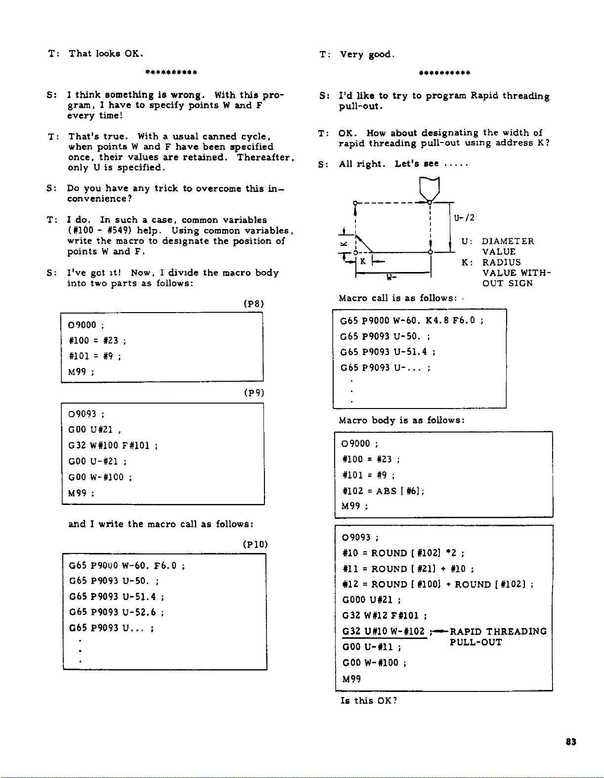
T:
That
looks
OK.
T:
Very
good.
I
S:
think
gram,
every
That's
T:
when
once,
only
S:
Do
convenience?
do.
T:
I
(#100-#549)
write
points
I've
S:
into
09000
#100
#101=#9
M99
points
U
you
the
got
two
=
;
something
have
1
time!
true.
values
their
is
specified.
have
In
such
macro
W
and
it!
parts
;
;
#23
;
**********
is
wrong.
to
specify
a
With
W
any
a
help.
F.
Now,
as
usual
andFhave
are
trick
case,
Using
to
designate
divide
I
follows:
points
canned
been
retained.
overcome
to
common
common
the
With
W
specified
variables
the
macro
pro¬
this
and
F
cycle,
Thereafter,
this
variables,
position
body
(P8)
in¬
of
S:
T:
S:
I'd
like
pull-out.
OK.
rapid
All
right.
r
\
-
Macro
G65
P9000
G65
P9093
P9093
G65
G65
P9093
to
try
about
How
threading
W-
call
is
**********
to
designating
pull-out
Let's
a
as
follows:
W-60.
U-50.
U-51.4
.
.
U-.
program
see
4_i
K4.8F6.0
;
;
;
using
U-/2
U:
K:
Rapid
the
address
DIAMETER
VALUE
RADIUS
VALUE
OUT
;
threading
width
of
WITH¬
SIGN
K?
09093
GOO
G32
GOO
GOO
M99
and
G65
G65
G65
G65
G65
;
U
#21
W#100
U-#21
W-#100
:
write
I
P9000
P9093
P9093
P9093
P9093
,
F
#101
;
;
the
W-60.
U-50.
U-51.4
U-52.6
U...
;
macro
F6.0
;
;
;
;
call
;
as
follows:
(P9)
(P10)
Macro
09000
#100
#101
#102
M99
09093
#10
#11
#12
G000
G32
G32
GOO
GOO
M99
body
;
#23
=
#9
=
ABS
=
;
;
ROUND
=
ROUND
=
ROUND
=
U#21
W#12
U#10
U-#ll
W-#100
as
is
;
;
#6]
[
#102]
[
#21]
[
[#100]
;
F#101
W-#102
;
;
follows:
;
;
y
;
*2
+
;
#10
+
ROUND
RAPID
PULL-OUT
[#102]
;
THREADING
this
OK?
83
Is
Page 94
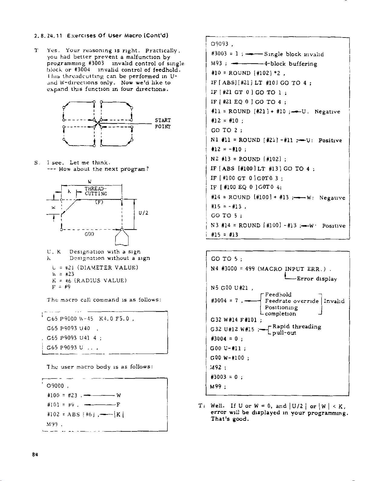
2.8.24.11
Yes.
T
you
programming
block
I
und
expand
Exercises
Your
had
or
!IIS
threndcutting
W-directions
/
i
O-
V
see.
Let
How
I
S.
---
,
*11
i
i
User
Of
reasoning
better
#3004
this
prevent
#3003
invalid
only.
function
?
f
I
1
can
h—
i
i
i
i
me
think.
next
W
,
THREAD-
CUTTING
the
about
nr~
--
GOO
is
right.
a
invalid
control
be
Now
in
four
program?
T
Macro
(Cont'd)
Practically,
malfunction
control
of
performed
we'd
directions.
\
i
?
T
i
/
U/2
by
of
single
feedhold.
in
to
like
START
POINT
U-
09093
#3003
M93
#10
=
[
ABS]
IF
[
IF
#21
#21
[
IF
#11
=
#12=#10
TO
GO
N1
#11
#12
=
N2
#13
[ABS
IF
[
#100
IF
IF
I
#14
=
#15
=
GO
TO
3
N
#14
i
#15
=
.
;
1
=
;
—
—
ROUND
GT
EQ
ROUND
2
=
-#10
=
#100
ROUND
-
#1
5
=
#13
]
[
#21
]
0
]
0
;
;
ROUND
;
ROUND
[#100
GT
0
EQ
0
,
3
;
ROUND
[#102]
LT
GO
GO
[#21
]LT
]
]G0T0
[#100]
Single
4-block
#10]
TO
TO
]
[
#21
[
#1021
#13]
GOTO
[#100]
+
*2
#10
]
3
4;
+
block
invalid
buffering
,
;
;
TO
;
TO
4
.
U
U
4
W:
GO
1
4
-#11
;
#13
;
;
;
GO
---
;ÿ
-#13
•W
Negative
:
Positive
Negative
•
Positive
.
I
U,
K
K
L
W
K
F
The
G65
G65
G65
G65
The
09000
#100
#101
#102
M99
Designation
Designation
»2l
=
#23
=
#b
=
#9
=
macro
P9000
P9093
P9093
P9093
user
,
#23
=
F9
=
ABS
=
.
(DIAMETER
(RADIUS
call
-
45
\\
40
U
U41
..
U
macro
.
-
-
.
—
#6]
[
a
with
without
VALUE)
command
K4.
,
;
4
,
body
VALUE)
0
F5.
as
is
W
|
|
K
sign
is
0
a
sign
as
follows:
,
follows:
--
T:
GO
4
N
5
N
#3004
32
G
32
G
#3004
GOO
GOO
M92
#3003
M99
Well.
error
That's
5
TO
#3000
GOO
U#2l
7
=
W
#14F#101
U#12
0
=
U-#ll
W-#100
;
0
=
;
If
will
good.
;
499
=
-
W#15
;
;
;
;
U
or
be
(MACRO
.
“Feedhold
Feedrate
Positioning
completion
-
;
;
[
-
0,
W
=
displayed
INPUT
Rapid
pull-out
ERR.)
Error
override
threading
display
and|U/2|or|w|<K,
in
your
programming.
.
Invalid
84
Page 95

2.8.25
Program
NC
the
around
G
of
(1)
(2)
Details
When
ed
in
PROGRAM
mirror
program
the
command.
;
G68
;
69
G
When
program
operation
axis
verted
manual
The
and
feed
this
by
the
movement
the
with
following
the
work
•••
•••
with
handle
feature.
of
X-axis
Z-axis
inversion
NC
MIRROR
image
operation
center
Program
The
program
state
fied.
Program
The
program
state
.
fied
mirror
by
Z-axis
operations
program
by
being
unit:
is
is
is
the
/step
mirror
the
the
line
mirror
held
mirror
held
being
mirror
is
IMACE
feature
in
all
(2-axis)
mirror
until
mirror
until
image
program
NC
the
(manual
feed)
image
image
NC
program
center
the
processed
(C68,
directions
image
image
G69
image
image
G68
on,
is
center
continuous
not
are
feature
to
by
on.
is
off.
IS
line.
069)
reverse
the
on
speci¬
off
speci¬
the
in¬
is
line.
affected
is
invert¬
is
X-
The
+
use
on,
h.
i.
j.
+X
operational
The
position
command
T
tool
tion
G
command
tion
virtual
compensation
for
nose
for
tool
X
N
VIRTUAL
VIRTUAL
center
>
1
N
K.
TOOL
TOOL
Fig.
direction
nose
tool
nose
tool
nose
/WIN
CENTER
*
~
NOSfr
SOS)
'TOOLS
CENTER
2.40
is
is
inverted
position
radlut
\
i
Tool
y
Virtual
Compensation
and
G4
mirror
tion
after
inverted.
radius
radius
coopsnsation
cantar
OIXE
T
C41
tool
A
whan
is
X-axis
compensa¬
in
the
compensa¬
is
inverted.
‘“1
tool
nos*
2
+
T-UDDD
canter
X-axis
usage
func¬
on.
tool
sign.
,
a.
b.
c.
d.
e.
f.
command
X
inverted
U
command
value
command
I
arc
center
Circular
+x
I
command
volume
command
I
distance
for
.
for
inverted.
is
for
is
motion
CHANCED
TO
CO
3
for
and
for
is
X-axis
X-axis
X-axis
inverted.
direction
I
PROGRAMMED
ROTATIONAL
v
CIRCULAR
DIRECTION
WITH
FEATURE
Fig.
X-axis
direction
canned
inverted.
coordinate
incremental
coordinate
inverted.
CIRCULAR
DIRECTION
ARC
ROTATIONAL
MOVEMENT
X-AXIS
ON
IN
MIRROR
IMACE
2.39
beveling/rounding
inverted.
is
cycle
taper
value
coordinate
value
ARC
X-axis
is
of
g.
U
and
finishing
commands
I
allowance,
for
special
etc.
are
canned
inverted.
cycles
85
Page 96

2.8.25
(CONT’D)
(3)
Cautions
a.
G68
belong
fied
b.
G69
the
program
.
These
c
tool
state.
d.
These
finishing
cycle.
e.
If
is
feature
mediate
ed
origin,
affected
X
+
PROGRAM
for
G69
and
to
a
on
single
(program
time
of
reset.
commands
nose
radius
commands
shape
automatic
specified
is
point
the
by
which
by
MIRROR
G68
are
"10"
group.
block
mirror
power-on,
compensation
program
origin
when
on,
the
specified
mirror
is
an
feature.
this
X
C28
7-
PROGRAMMED
MEDIATE
and
G69
modal
image
must
not
may
return
the
X-axis
positioning
image,
absolute
Z
INTER¬
POINT
IMAGE
commands
G
commands
They
basis,
reset
be
specified
be
of
in
but
must
in
off)
operation,
specified
the
"G28
mirror
X
and
the
position,
(C68,
which
be
principle.
is
used
in
cancelled
special
X---
the
of
is
Z
machine
ABSOLUTE
4-
G69)t
speci¬
the
in
canned
z-
image
inter¬
affect¬
is
ZERO
POINT
at
and
the
•
not
Power
on
+
+
X40.
X80.
50
X120.
reference
execution
X240.
Z120.
;
-
U480.
Z80.
;
-
U480.
Z40.
:
TD1
Z220.
T0101
;
Tllll
T0101
point
X-axis
mand
display
;
-
;
-
;
—
;
—
return
com¬
value
240.000
96.000
-96.000
+384.000
+144.000
-144.000
336.000
-
176.000
OFFSET
220.
|
_
TURRET
A
X-axis
movement
U-144.000
U240.000
U-
.
160
01
X56.
.
Z8
000
Manual
Program
N0001
N0002
N0003
N0004
N0005
N0006
I)
.
•
N0007
N0008
G50
G68
G50
G69
G
+
x
t
EXAMPLE
Described
G68
uses
shown
and
in
the
below
and
the
X-axis
n7
Fig.
is
G69
for
diagram
movements.
2.41
sample
a
the
on
program
opposed
following
the
z
tool
which
rest
page,
52
roi
82
120
80
n
+
ss
1
S2
T01
i
l
TURRET
B
OFFSET
11
L
2"
I
X|4.
g
86
Page 97

2.8.26
(C70
MULTIPLE
C76)
TO
t
REPETITIVE
CYCLES
(3)
The
ing
internal
shape
memory
program:
for
storing
the
finish¬
2.8.26.1
This
instance,
For
performed
are
work
ing
C
code
G70
C71
72
G
G73
C74
G75
G
76
(1)
(2)
option
Table
Finishing
Stock
Stock
Pattern
Peck
Grooving
Automatic
G70
modal.
The
G71,
by
The
45
is
General
makes
both
only
shape.
2.
21
cycle
removal
removal
repeating
drilling
in
through
program
G72
memory
blocks.
program
stock
by
Multiple
Name
in
turning
lacing
in
axil
in
Z
axis
X
threadcutting
G76
of
finishing
and
capacity
simple
removal
commanding
Repetitive
Fimahing
70
by
C
poasible
Tip
nose
impossible
are
in
*
shape
are
G73
for
stored
the
and
and
Remark!
ridius
group
finishing
short.
finishing
the
finish¬
Cycles
Tip
compensation
possible
compensation
and
specified
in
note
radius
non-
memory.
shape
To
tation
binary-converted
memory
(one
called
shape
program
(4)
In
G76,
specified
group
may
by
(5)
It
compensation
G73.
(6)
Tool
performed
Any
shorten
pair)
the
the
have
the
is
possible
nose
attempt
the
time,
the
for
storing
in
internal
the
program,
memory.
block
codes
G
again.
G
codes
been
execution
radius
on
stock
the
after
specified
changed
to
on
the
do
to
removal
finishing
then
and
finished
unit.
memory
which
cycle
the
of
01
This
is
of
this
perform
cycle
the
compensation
cycle
so
will
shape
This
differs
group
because
before
to
cycle.
tool
of
G74
of
result
is
shape
memory
for
of
other
nose
G70
cycle
program
stored
finishing
from
G70
should
the
the
G
radius
through
cannot
through
in
compu¬
m
the
program
is
the
part
through
be
01-
cycle
codes
be
G76.
an
error.
is
Program
Note'
multiple
each
ed
as
Gil
One
Gill
When
block
the
One
One
G112
of
cornering
containing
value
block
or
12
G
block
block
finishing
cornering
listed
including
including
including
(Gill,
shape
(Gil,
them
below
G112)
must
.
No
of
Two
Four
Five
45
S
G12)
blocks
blocks
blocks
blocks
blocks
and
are
be
used,
count¬
87
Page 98
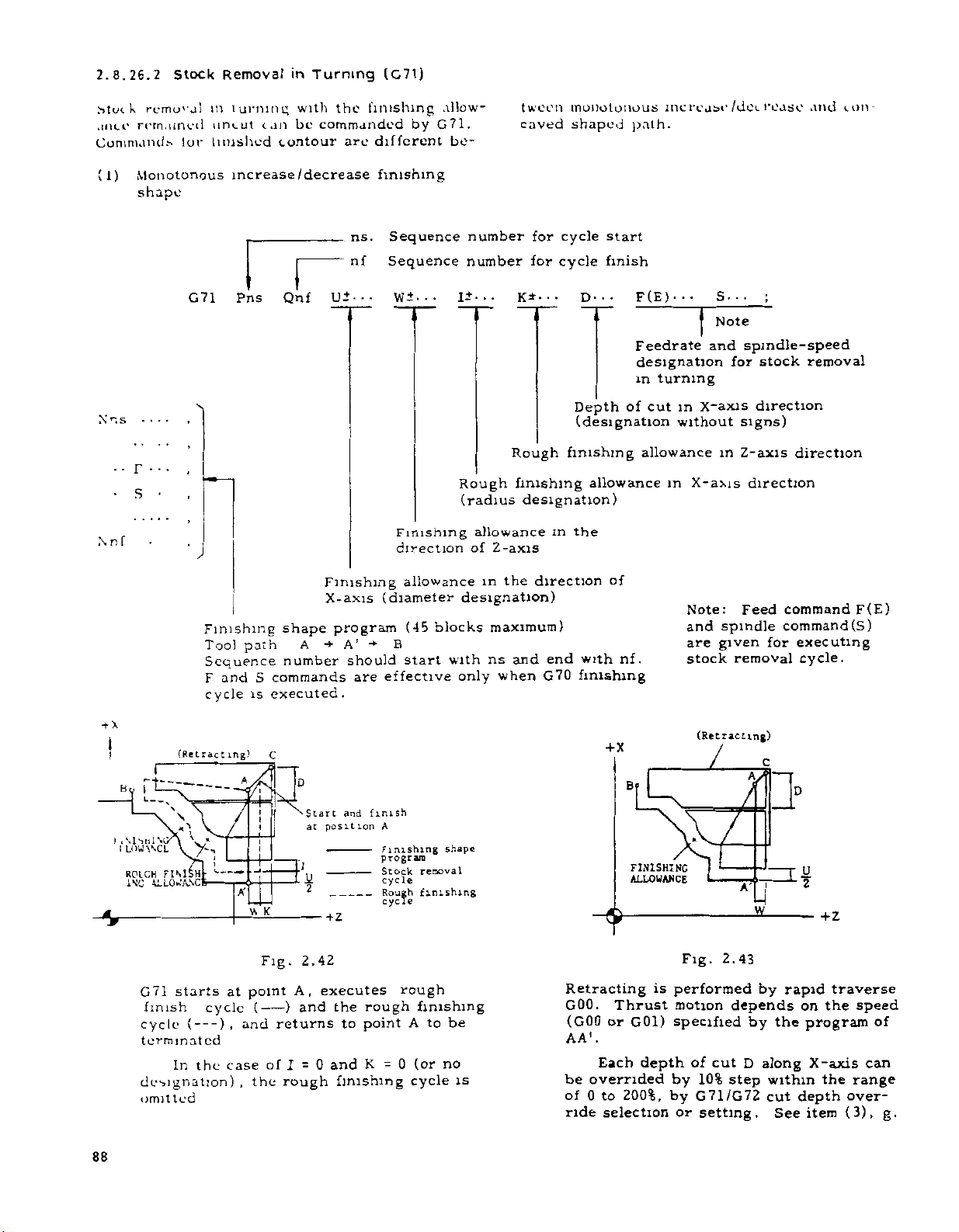
2.8.26.2
removal
k
Mut
remained
ance
Commands
Stock
lor
Removal
in
turnmi;
uncut
tnushcd
can
contour
in
Turning
with
commanded
be
the
are
(G71)
finishing
by
different
allow¬
G71.
be-
tween
caved
monotonous
shaped
path.
increase
/dot.
reuse
and
u»n
(1)
Nns
•
n
Monotonous
shape
S
f
71
G
Finishing
Tool
Sequence
F
cycle
increase
and
Pns
path
is
Qnf
shape
number
S
commands
executed
/decrease
I
U±*
Finishing
X-axis
program
-*•
A
ns.
nf
••
A’
should
are
.
finishing
Sequence
Sequence
W
Finishing
direction
(diameter
-*•
B
effective
+
...
allowance
(45
blocks
with
start
number
number
+
!
K*
Rough
allowance
Z-axis
of
the
in
finishing
Rough
(radius
designation)
maximum)
and
ns
when
only
for
cycle
for
cycle
•
D--.
•
Depth
(designation
finishing
allowance
designation)
in
the
direction
with
end
finishing
G70
start
finish
of
of
nf.
F(E)
•
Feedrate
designation
in
turning
cut
m
without
allowance
in
Note:
and
are
stock
•
and
X-axis
X-axis
.
S.
Note
spindle-speed
stock
for
direction
signs)
in
Z-axis
direction
Feed
spindle
given
removal
;
direction
command
command(S)
executing
for
cycle.
removal
F(E)
88
I
By
I
L
,\lsul\G
I
I
LOWWCL
ROICH
INC
G7]
finish
cycle
terminated
designation)
omitted
(Retracting)
r
--
V
A
ft
>7
'
M-UKASCS
---
r—
-
—
A
VI
starts
In
at
point
),
case
and
,
{
the
-
cycle
(
---
the
C
K
Fig.
of
D
Start
at
2
2.42
A,
)
and
returns
I
=
rough
and
position
executes
the
to
and
0
finishing
finish
A
Finishing
program
Stock
cycle
Rough
cycle
rough
point
K
=
removal
finishing
rough
finishing
A
(or
0
cycle
Fig.
is
performed
motion
specified
(Retracting)
f
*'U
2.43
depends
by
w
by
if
rapid
the
traverse
on
the
program
speed
of
X
+
B'
shape
FINISHING
ALLOWANCE
Retracting
GOO.
to
be
(GOOorG01)
Thrust
AA1.
no
of
by
by
or
cut
10%
step
G71/G72
setting.
D
along
within
cut
See
X-axis
depth
item
depth
Each
overrided
is
be
of
ride
0
to
selection
200%,
the
can
range
over¬
(3),
g.
Page 99

NOTES:'
1.
2.
+x
B
tool
The
programmed
decrease
following
The
in
ation
and
programming
the
end
program.
MONOTONOUS
X:
INCREASE
'ÿ
MONOTONOUS
A
al
INCREASE
r?
K
K
MONOTONOUS
X.
DECREASE
MONOTONOUS*.
2:
INCREASE
Nnf
BA
IS
IN
of
path
be
to
in
and
X
should
block
%
A
'
-V-
A
PARALLEL
finishing
monotonous
Z
coordinates.
be
the
(Nnf)
B
+x
°
IS
AA
PARALLEL
X
AXIS
WITH
Z
AXIS
shape
increase
taken
into
start
of
a
finishing
WNOTONOUS
X:
INCREASE
MONOTONOUS
:
Bt
DECREASE
+z
9
9
MONOTONOUS
:
DECREASE
MONOTONOUS
DECREASE
IN
WITH
should
block
1
Specified
I
in
|
C01
I
be
or
consider¬
(Nns)
shape
A
K
K
A
COO
or
node
1:
Note
spindle
and
of
stock
2:
Note
concaved
specified.
a
ft
X
%
+x
&
G71
cutting
cycle
terminated.
finishing
Retracting
GOO.
(GOO
AA\
can
range
override
8-
Specifies
command
removal
Computes
finishing
\
starts
///
at
cycle
(
)
,
and
cycle
---
is
Thrust
G01)
or
Each
depth
be
overrided
0
to
of
selection
feed
the
(S)
for
cycle.
cutting
the
shape
detract
r
h
//ROUGH
program
ing)
\
\
—
2BHHÿ
FINISHING
SHAPE
STOCK
ROUCH
A,
)
and
returns
is
not
skipped.
depends
cut
of
10%
by
by
or
executes
setting.
point
(
-
If
I
is
performed
motion
specified
200%,
command
the
path
J-
—
FINISHING
ALLOWANCE
SHAPE
REMOVAL
FINISHING
the
rough
to
point
specified,
rapid
by
the
by
along
D
step
G71/G72
(F(E))
execution
for
if
R1
z
At
//A
A
CYCLE
CYCLE
the
finishing
A
the
traverse
on
the
program
X-axis
within
cut
See
the
is
POSITION
SHIFTED
FKOH
A
(CUTTING)
U/2
rough
to
rough
speed
the
depth
item
BY
be
of
Pol
0/2*1
D
(3)
Iff
,
&
(2)
Nns
•
Nnf
a.
•
F
•
S
Concaved
Command
G71
Pn*
finishing
format
Qnf
Ui
“Finishing
Tool
n#
Sequence
nf
Sequence
•
IT
TT
Finishing
—
X-axis
shape
path
A
contour
D
‘-Depth
Rough
direction
(diameter
program
A1
for
number
for
number
F(E)
Note
1
of
finishing
(radius
designation)
(45
B
cut
blocks
(designation
allowanceinthe
cycle
start
cycle
R
S
in
X*axis
without
allowance
designation)
direction
maximum)
finish
1
Note
signs)
in
,
2
direction
X-axis
of
b.
COMMAND
OF
FINAL
OF
FINISHING
SHAPE
PROGRAM
Cautions
gram
(i)
POINT
BLOCK
Rough
the
&
B’
T
for
cutting
closest
concaved
cycle
concave
©
o®
t
0.
finishing
G71
by
the
to
SL
©
A
starts
start
©
©
shape
point.
©
©
a
pro¬
from
i
*
COWAN!)
Bli»U
1bT
Of
FINISHING
PROGRAM
.
m
POINT
HlAPk
Of
89
Page 100

2.8.26.2
CONT’D)
Since
nearest
is
yond
its
turns
cutting
CUTTING
B<1
DISCONTINUED
POINT
\
(11)
For
point
concave
a
is
then
Stock
cutting
the
interrupted
the
bottom.
to
beyond
BEYOND
ZISCONTINl
POINT
a
simple
is
provided.
containing
convex
interrupted
the
at
DISCONTINUATION
Removal
starts
start
concave.
Then,
the
interrupted
it.
DISCONTINUATION
_
-
concave,
shown
as
first
smaller
in
Turning
with
the
the
hits
concave
The
the
cutting
//PATH1NG
-
y
ION
CAVE
if
point,
it
only
However,
smaller
a
below,
the
at
convex.
t
the
point
the
concave
cutting
convex
one
for
concave
cutting
larger
(G71)
path
be¬
cut
is
re¬
cycle
to
perform
DEPTH
CUT
D
interrupted
a
complex
convex
OF
and
path
(ill)
Any
contour
allow
cutting.
cation
value
should
(IV)
The
termination
to
program
BA
B
Nnf**»"
the
For
(Nnf
•
IS
•
•
having
of
be
a
monotonous
the
has
PARALLEL
1
G
command
)
;
,
specify
Hence,
the
block
following
TO
Z
overhang
an
the
finishing
variation.
for
AXIS
AA'
/
A
PARALLEL
the
of
G01
Z-axis
shape
the
finishing
limitations:
START
A
POINT
*
I
Nni**
NEED
termination
or
GOO
does
specifi¬
program
NOT
BE
TOXAXIS
,
in
princi¬
not
shape
block
pal.
(v)
The
cycle
retracting
may
\
N
amount
be
set
by
RETRACTING
(FOR
#6202
after
the
setting.
AMOUNT
C7I)
each
SETTING
approach
e
B
The
points
yond
"097"
number
Sample
CONVEX
CONVEX
CONCAVE
maximum
that
which
error.
number
allows
cutting
Within
concaves
of
DISCONTINUATION
Contour
CUTTING
PATH
DISCONTINU¬
2
ATION
.CUTTING
PAT]
CONCAVE*’
interrupted
of
cutting
is
DISCONTINU¬
ATION
Not
is
disabled,
limitation,
this
allowed.
is
1
CUTTING
DISCONTINUATION
2
CUTTING
DISCONTINUE
AT
CUTTING
i
4
Allowing
three,
ION
PATH
A
X
A
causing
PATH
PATH
3
NG
A'
Cutting
be¬
any
/
I
PATH
(vi)
Each
should
tonous
extends
be
divided
block
be
decrease.
over
s
\
of
the
of
monotonous
two
into
two
CUTTING
finishing
A
circular
or
more
blocks
PATH
increase
shape
arc
quadrants
before
program
or
mono¬
which
roust
being
programmed.
(vn)
Generally,
K
and
is
caused
side.
tional
(vni)
crease
Approach
not
is
It
A
finishing
pending
positioning
traverse
Z-axis
are
not
into
"Rl"
If
monotonous
stock
removal
is
performed
affected
shape
on
the
may
after
finishing
specified.
the
wall
not
is
increase
by
program.
finishing
be
performed
approach
the
4
Otherwise,
the
of
specified,
/monotonous
cycle
the
at
the
G
Hence,
shape
A
allowances
corresponding
the
is
provided.
feedrate.
code
of
program,
by
rapid
feedrate.
at
APPROACH
a
conven¬
the
de¬
W
bite
de¬
90
7/
 Loading...