

Page 1
.....
>
......
:•
-
:
...
%
YASKAWA
ELECTRIC
Ha
This
which
ing
the
ance
manual
ftfi
88
manual
is
an
man-machine
14-inch
Operators
before
describes
option
color
should
using
YASNA
C
LX
/MX
3
ACGC
CONNECTING
the
connection
YASNAC
the
of
function
thoroughly
120.
CRT.
the
interface
become
ACGC
MANUAL
with
LX3/MX3
with
the
the
familiar
series,
3
120
with
120,
featur¬
this
ACGC
high-perform¬
ACGC
1.
1.1
1.2
ENVIRONMENTAL
2.
STRUCTURAL
3.
THERMAL
4.
4.1
4.2
CONNECTION
5.
SETTING
6.
MEMORY
7.
PRESHIPMENT
8.
8.1
8.2
8.3
EXTERNAL
9.
120
OVERVIEW
OVERVIEW
SELECTION
TOTAL
SYSTEM
SWITCHES
PARAMETERS
HEAT
OVERVIEW
THE
OF
OF
THE
CONDITIONS
DESIGN
DESIGN
THE
OF
GENERATION
DIAGRAM
MODULE
THE
SPACE
SETTINGS
GENERATION
DIMENSIONS
TABLE
PRODUCT
CONTROL
OF
THE
THE
OF
HEAT
SHORT-CIRCUIT
(INITIAL
OF
MODULE
CABINET
CABINET
EXCHANGER
OF
EACH
SETTING)
CONTENTS
••••
UNIT
PLUG
SWITCHES
2
2
4
5
5
6
6
7
8
20
22
23
23
24
26
27
BATTERY
10.
SUPPLEMENT
this
manual,
The
In
meaning.
MAINTENANCE
terms
the
“portable"
terms
“(printed
and
circuit)
"stand-alone"
board
are
(card)"
also
used
and
with
“module"
same
the
used
are
meaning.
with
the
31
same
Page 2
1f
ACGC-1
1.
OVERVIEW
1.1
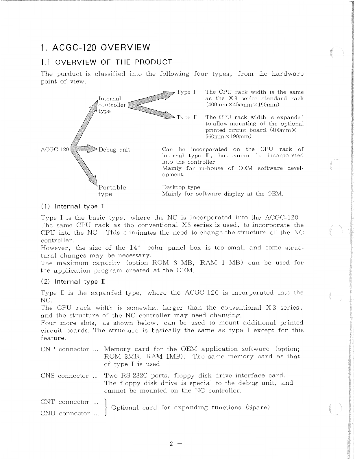
porduct
The
point
ACGC-120
(1)
of
Internal
view.
OVERVIEW
20
OF
is
classified
Internal
controller
fj
type
r
Debug
Portable
type
type
I
THE
unit
PRODUCT
into
the
P
following
Type
Type
be
Can
internal
into
the
Mainly
opment.
Desktop
Mainly
four
I
H
incorporated
type
controller.
in-house
for
type
for
software
types,
The
the
as
(400mm
The
to
allow
printed
560mm
,
II
CPU
CPU
X
but
display
from
rack
series
3
X
X
450mm
rack
mounting
circuit
190mm)
on
cannot
OEM
of
width
width
board.
the
at
the
standard
190mm)
X
of
CPU
be
software
the
hardware
is
the
same
.
expanded
is
optional
the
(400mm
rack
incorporated
devel¬
OEM.
rack
X
of
Type
The
CPU
I
same
into
controller.
However,
tural
The
the
(2)
Type
changes
maximum
application
Internal
H
NC.
CPU
The
the
and
Four
more
circuit
feature.
CNP
CNS
connector
connector
the
is
CPU
the
the
is
the
rack
structure
slots,
boards.
basic
rack
NC.
size
may
capacity
program
type
expanded
width
The
...
...
type,
as
This
of
be
H
the
of
as
shown
structure
Memory
ROM
type
of
Two
The
cannot
where
the
eliminates
the
14"
necessary.
(option
created
type,
somewhat
is
NC
3MB,
I
RS-232C
floppy
be
the
conventional
the
color
ROM
at
where
controller
below,
basically
is
card
for
RAM
used.
is
ports,
disk
mounted
NC
panel
the
larger
can
the
1MB)
drive
need
3
OEM.
the
may
be
floppy
on
is
X3
MB,
OEM
is
the
incorporated
series
change
to
box
is
RAM
ACGC-120
than
the
need
used
the
same
application
The
.
same
disk
special
NC
controller.
used,
is
the
small
too
MB)
1
is
conventional
changing.
to
mount
type
as
memory
drive
to
the
into
the
incorporate
to
structure
and
can
incorporated
additional
except
I
software
card
interface
debug
ACGC-120.
of
the
some
be
struc-
used
into
X
series
3
printed
for
(option;
as
card.
unit,
and
this
that
the
NC
for
the
i
i
,
1
CNT
CNU
connector
connector
...
...
Optional
card
for
expanding
2
functions
(Spare)
I
Page 3
(3)
Debug
r
unit
Used
The
when
open
conditions.
The
same
incorporated
be
mounted
CNP
CNS
CNT
connector
connector
connector
developing
type
CPU
on
the
unit
rack
into
expanded
Memory
...
ROM
of
However,
enable/
Two
...
The
is
development
(PC-9800
The
NC
RAM
...
ware.
ing
space,
by
to
slot
the
to
is
that
as
the
3MB,
type
RS-232C
3.5-inch
used
3.5-inch
controller.
memory
address
the
change
into
application
be
used
of
NC
controller.
4
slots
card
RAM
I
is
used.
special
disable
floppy
upload/
to
environment
series)
floppy
Two-MB
setting
in
rotary
a
MB
1
the
RAM,
in
internal
are
the
for
1MB).
notice
status
ports,
with
card
RAM
unit.
switch
ROM
and
software
location
type
As
as
follows.
OEM
of
floppy
disk
download
the
disk
development
for
is
anywhere
The
on
area
cannot
at
having
It
in
application
The
must
the
disk
drive
the
of
the
debug
drive
mounted
address
the
card.
on
the
is
type
same
be
ROM
can
NEC
cannot
in
the
be
OEM.
favorable
used,
,
II
memory
taken
on
drive
be
software
unit.
of
on
a
the
setting
This
memory
applied
but
the
software
when
this
interface
used.
created
personal
be
mounted
the
single
1
to
card
to
environmental
unit
the
cards
that
(option:
card
setting
card.
as
card.
This
connector
in
computer
on
application
card,
MB
16
simply
is
designed
is
card
the
of
product.
cannot
are
that
the
the
the
soft¬
allow¬
memory
done
the
;
1st
CNU
In
for
(4)
The
side
the
can
tion
•
Two
•
Cabinet
•
•
•
connector
addition
debugging.
Full
CRT
9"
O
1/
Portable
ACGC-120
does
showroom
debugged.
be
machine.
3.5"
...
to
the
keyboard
panel
simulator
type
not
function.
at
The
floppy
specialized
Same
above,
control
the
It
features
disk
card
OEM.
can
drives
for
as
the
This
also
15"
the
following
alone
type
The
be
are
in
color
CNT
expanded
as
the
connector
optional
is
stored
provided
is
application
follows.
standard
CRT
(incorporating
peripheral
in
a
for
software
into
an
configuration
specialized
displaying
automatic
a
of
TV
tools
the
tuner)
are
box.
the
OEM
program
offered
The
system
f
NC
in
alone
crea¬
-3-
Page 4
OVERVIEW
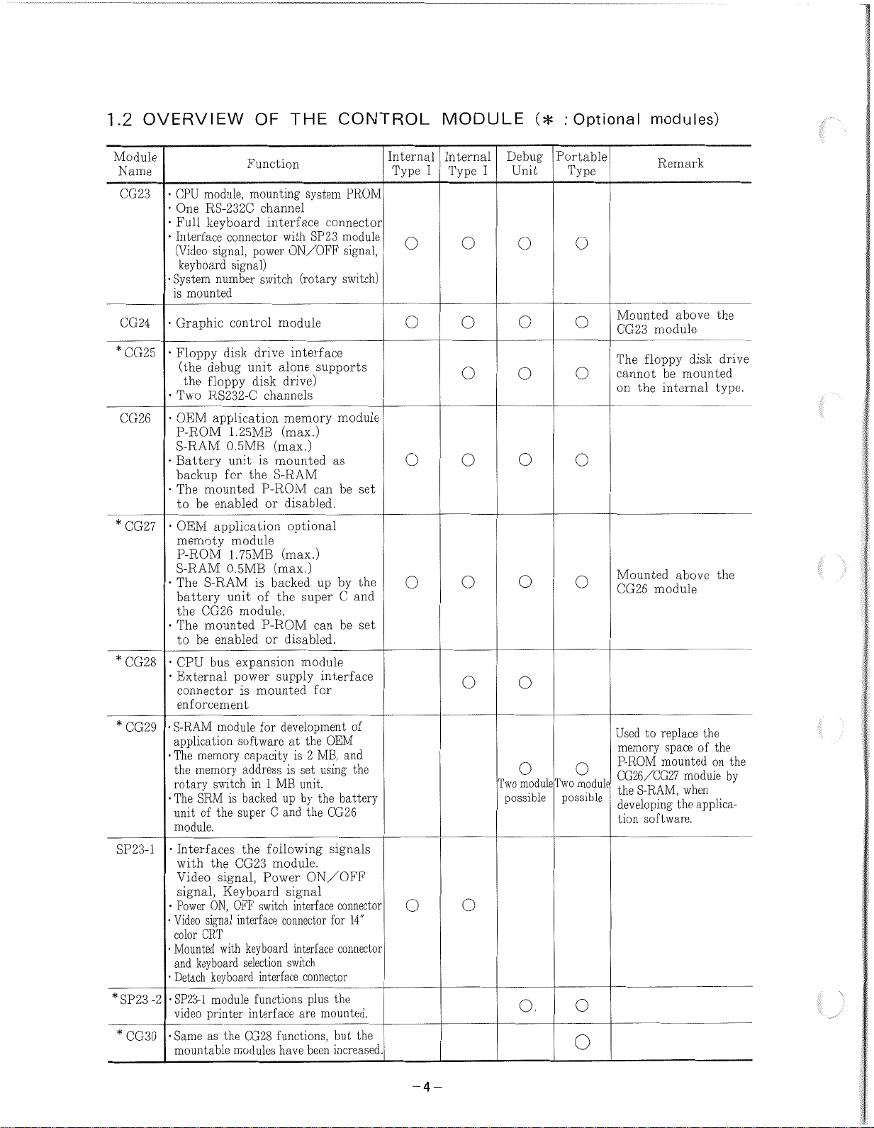
1.2
Module
Name
CG23
CG24
CG25
CG26
*
CG27•OEM
*
CG28
*
CG29
SP23-1
-2
*SP23
*
CG30•Same
•
module,
CPU
•
One
RS-232C
•
keyboard
Full
•
Interface
(Video
signal,
keyboard
•
System
number
is
mounted
•
Graphic
•
Floppy
(the
debug
floppy
the
•
RS232-C
Two
•
•
•
OEM
P-ROM
S-RAM
Battery
backup
mounted
The
to
be
memoty
P-ROM
application
enabled
application
S-RAM
•
S-RAM
The
battery
CG26
the
•
The
mounted
to
be
enabled
•
CPU
bus
•
External
connector
enforcement
•S-RAM
application
•
The
rotary
•
The
unitofthe
module.
•
•
•
Video
color
•
Mounted
and
•
•
SP23-1
module
memory
memory
the
switch
SRM
Interfaces
with
the
signal,
Video
signal,
ON,
Power
signal
CRT
keyboard
keyboard
Detach
module
printer
video
as
mountable
OF
Function
mounting
channel
connector
power
signal)
switch
control
disk
drive
unit
disk
1.25MB
0.5MB
unit
is
for
the
P-ROM
module
1.75MB
0.5MB
is
of
unit
module.
P-ROM
expansion
power
is
mounted
for
software
capacity
address
in
is
backed
super
the
CG23
Keyboard
switch
OFF
interface
keyboard
with
selection
interface
functions
interface
CG28
the
modules
THE
interface
with
ON/OFF
(rotary
module
interface
alone
drive)
channels
memory
(max.)
(max.)
mounted
S-RAM
or
disabled.
optional
(max.)
(max.)
backed
super
the
disabled.
or
module
supply
development
at
is
set
is
unit.
1
MB
up
by
C
and
following
module.
Power
signal
interface
connector
interface
switch
are
functions,
have
CONTROL
system
PROM
connector
SP23
module
signal,
switch)
supports
module
as
be
can
by
up
C
be
can
interface
for
OEM
the
MB,
2
and
using
battery
the
CG26
the
signals
ON/OFF
connector
for
14"
connector
connector
plus
the
mounted.
but
been
increased.
and
of
the
set
the
set
the
Internal
Type
I
o o
o
o
o
o
MODULE
Internal
Type
Debug
I
o o
o o
o o
o
o
Two
possible
o
(*
:
Portable
Unit
o
o o
o
o
Two
module
possible
o.
Optional
Type
o
o
o
o
o
module
o
o
modules)
Remark
Mounted
CG23
The
cannot
on
Mounted
CG26
Used
memory
P-ROM
CG26/CG27
the
developing
tion
above
module
floppy
mounted
be
internal
the
above
module
replace
to
space
mountedonthe
S-RAM,
module
when
the
software.
the
disk
type.
the
the
the
of
applica¬
1
drive
by
Tv
-4-
Page 5
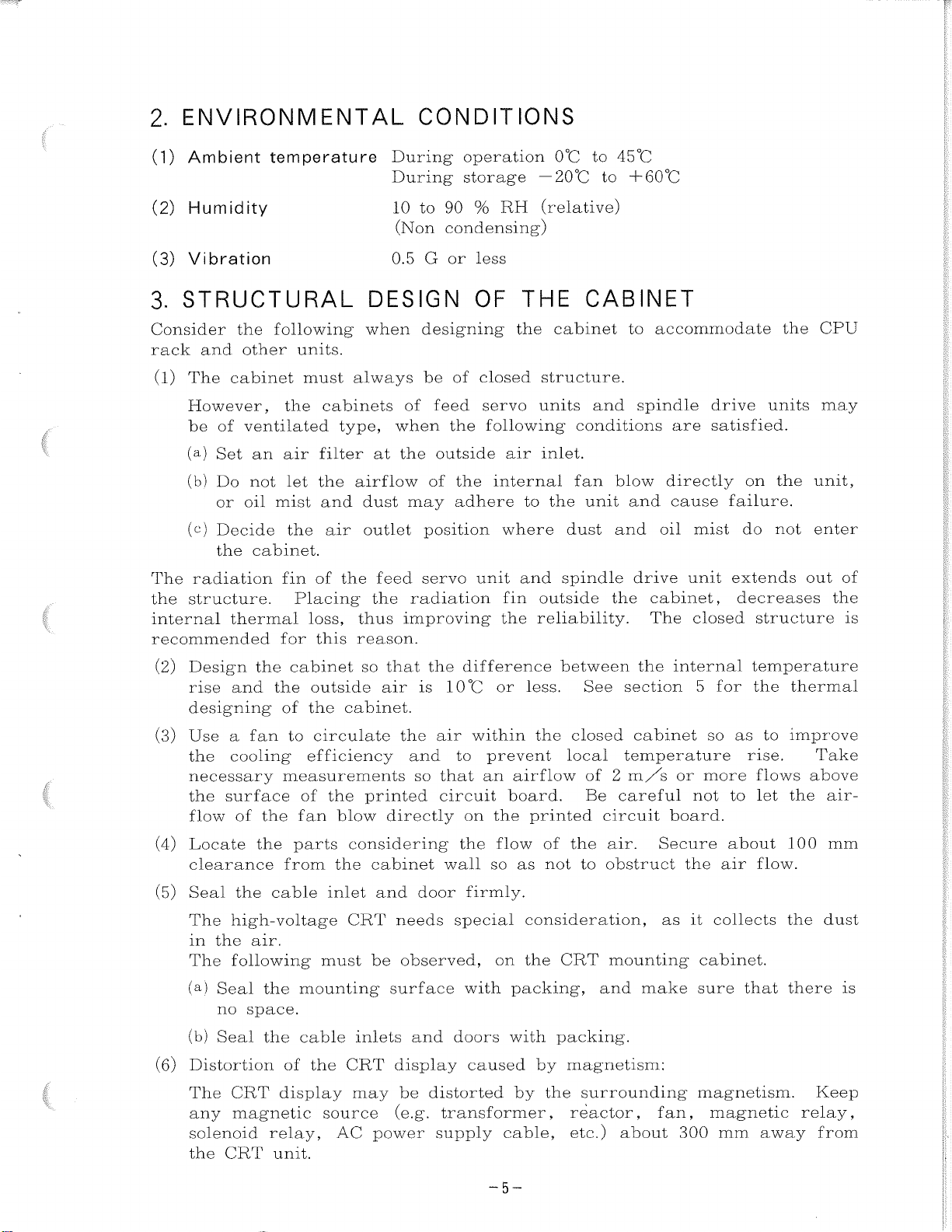
ENVIRONMENTAL
2.
CONDITIONS
(1)
Ambient
(2)
Humidity
(3)
Vibration
STRUCTURAL
3.
Consider
rack
(1)
The
However,
be
(a)
(b)
(c)
The
structure.
the
internal
the
and
other
cabinet
of
Set
Do
or
Decide
the
radiation
thermal
ventilated
an
not
oil
cabinet.
recommended
(2)
Design
rise
designing
the
and
temperature
following
units.
must
cabinets
the
filter
air
let
the
mist
and
air
the
of
fin
Placing
loss,
this
for
cabinet
outside
the
the
of
DESIGN
when
always
type,
at
airflow
dust
outlet
feed
the
the
thus
reason.
so
that
air
cabinet.
During
During
to
10
(Non
G
0.5
designing
be
of
feed
when
outside
the
of
may
position
servo
radiation
improving
the
is
operation
storage
%
RH
90
condensing)
less
or
the
closed
servo
following
air
internal
where
unit
and
fin
the
or
THE
OF
of
the
the
adhere
difference
10°C
0°C
20
(relative)
cabinet
structure.
units
inlet.
to
the
dust
spindle
outside
reliability.
between
less.
to
45°C
to
°C
+60°C
CABINET
to
accommodate
spindle
and
conditions
blow
fan
unit
and
and
drive
cabinet,
the
The
the
See
section
are
directly
cause
oil
unit
internal
drive
satisfied.
mist
closed
for
5
units
on
failure.
do
extends
decreases
structure
temperature
the
the
the
not
thermal
CPU
unit,
enter
out
may
of
the
is
(3)
Use
the
necessary
the
flow
(4)
Locate
clearance
(5)
Seal
The
in
The
(a)
(b)
(6)
Distortion
/
The
any
solenoid
the
fan
a
cooling
surface
of
the
the
the
high-voltage
air.
the
following
Seal
no
Seal
the
space.
the
CRT
magnetic
CRT
circulate
to
efficiency
measurements
of
the
blow
fan
parts
from
cable
the
inlet
must
mounting
cable
of
the
display
source
relay,
AC
unit.
the
and
printed
directly
considering
cabinet
and
CRT
be
needs
observed,
surface
inlets
may
display
be
CRT
(e.g.
power
so
door
and
within
air
to
that
an
circuit
on
the
wall
firmly.
special
with
doors
caused
distorted
transformer,
supply
prevent
airflow
board.
the
flow
so
as
consideration,
the
on
packing,
with
by
cable,
the
printed
of
not
CRT
packing.
by
the
closed
local
of
Be
the
to
magnetism:
surrounding
reactor,
etc.)
cabinet
temperature
2
m/s
careful
circuit
air.
obstruct
mounting
and
make
about
or
board.
Secure
the
as
it
fan,
300
so
as
more
to
not
about
air
collects
cabinet.
sure
magnetism.
magnetic
mm
rise.
flows
let
flow.
that
to
away
improve
Take
above
the
100
the
dust
there
Keep
relay,
from
air¬
mm
f
is
-5-
Page 6

THERMAL
4.
DESIGN
OF
THE
CABINET
SELECTION
4.1
cabinets
The
closed
ambient
To
required
Determine
'Z\T
Pv
k
A
qh
.
(1)
Calculate
Pv
(2)
Calculate
A
+
structure,
air
satisfy
inside
Temperature
:
:
Total
:
Heat
Calculate
Effective
:
Required
:
2
X
2
|D
2
OF
that
accommodate
and
temperature.
the
cabinet,
the
the
heating
transmittance
with
radiation
heat
the
total
(Heating
effective
the
|W
(width)
(depth)
THE
the
above
capacity
rise
value
6
exchanger
heating
value
X
H
HEAT
the
internal
conditions
according
of
the
within
(W)
(W
W(m2-°C)
area
value
each
of
radiation
H
(height)
X
(height)
EXCHANGER
CPU
temperature
the
(m2
of
|
module
,
heat
•
°C
when
a
the
to
exchanger
cabinet
]
thermal
circulating
cabinet
effectiveness
Pv
of
the
unit)
area
A.
|
+
and
rise
installed
(degrees
(m2)
electric
|W
s
other
kept
heat
electrical
follows.
as
fan
parts.
(width)
units
within
exchanger
C)
is
X
are
10°C
parts.
provided.
(depth)
D
to
may
of
be
|
of
the
be
(3)
(4)
(5)
Surfaces
surfaces.
Calculate
rise
is
Pv'
heat
No
(Total
(Total
Qh
exchanger
=
Heat
that
When
this
the
2k
T
•
k
exchanger
heating
heating
(Pv
-
do
bottom
a
bottom
allowable
or
less
/AT
A
value)
value)
Pv'
not
surface
with
)
is
50mm
contact
is
considered
than
10°C
-
-6
necessary
is
the
/
/
or
less
above
a
non-effective
heating
10°C.
(W)
W/(m2.°C)
(Allowable
following
(Allowable
>
Z\T
the
the
outside
CTIVE
surface,
floor
surface.
amount
it
if
effectiveness
(W/°C)
air
Pv2
is:
heating
heating
are
,
as
value
value
considered
internal
the
)
Pv'
q
h
required
is
)
Pv'
non-effective
temperature
if
it
is:
u
10°C
-6-
Page 7

4.2
(1)
TOTAL
NC
unit
HEAT
GENERATION
OF
EACH
UNIT
(2)
ACGC-1
Control
CPU
NC
control
Tape
I/O
unit
20
Module/Unit
JANCD-CG23
JANCD-CG24
JANCD-CG25
JANCD-CG26
JANCD-CG27
JANCD-CD28
JANCD-CG29
JANCD-SP23
JANCD-CG30
14"
color
Unit
module
reader
module
CRT
panel
Heating
MAX.
Amount
5
6
2.5
5
1.5
0.1
0.5
2.5
0.1
100
TYP.70
Heating
(W)
Value
70
20
25
Optional
Optional
Optional
Module
Module
5
(W)
Remark
module
module
module
for
for
debug
portable
!
unit
type
1
/
:
-7-
Page 8

1
CONNECTION
5.
YASNAC
5.1
CNF
CNB
CN
CN6
CNZ
CND
CNC
20)
CN
CN2
CN
CN4
CNH
CN
(TU)
CNA
D
]
7
][
8
]
][*
JL
1
3
][
5
X
module
MEMORY
*
L-1
CNR
CNA
CG23
[
CNC
TZT
PC
MEMORY
MEMORY
10
POWER
CPS
(Internal
CONTROL
nr
PC
I/O
1
DIAGRAM
Optional
:
*
MAIN
BOARD
MB21
OR
MB20E
(OPT./SD)
CN
(HDLC)
(PC)
Note
2
SW5
(RS232C)
(OPT./SD)
(MM21)
(MM
(IO/SR)
(CPS)
LX3
]
BOARD
CG27
MEMORY
CG26
CNB
izr
£
£
CN49
CN48
CN47][]
GRAPHIC
24
CG
BOARD
CN21
20
CN22
BOARD
MM
BOARD
20
MM
BOARD
CN51
CN52
20
CN53
CN54
CN55
SUPPLY
CN
CN12][]
0N
CN13][]
(ACGC
ACGC
BOARD
D
BOARD
C
Note
1
ADDITIONAL
1
-
p[}
BOARD
][}
J
RS232C
B
21
A
MODULE
11
D
U
-
-
-
DIAGRAM
120)
120
CARD
MODULE
READER
Model
2801
I/O
2
B
-
I)
control
MODULE
type
CPU
RS232C
I/O
TAPE
GENERAL
unit
CONTROL
PANEL
r~
CN2
CN
MODULE
I/O
CNB
CN2
r-ac
CN3
I-OC
[CN1
{][
CN
X
_
_o
CNB
SP23
1
-
1
I
CNA
SP20B
SERVO
1st
SERVO
2nd
1
SPINDLE
UNIT
ESP
-oTo-i
CNC
CNA
CNE
CND
CN
CN
CN4
CN
UNIT
AXIS
CN
UNIT
AXIS
CN2]Q
DRIVE
o
Q
i
—
INTERCONNECTION
]ÿ
[JÿEVBOARD|]
—
LF
Note
MACHINE
SVM
NCM
2
o-
o-l
6
1
5
2
30
EXT.
POWER
ON
OFF
r
o
d
—
CONTROL'PANEL
IN
POINT
48
POINT,
16
IN
VOLTAGE
HIGH
DIRECT
IN
POINT
IN
40
POINT,
8
IN
POINT,
IN
24
POINT
IN
40
POINT
IN
40
i
FKEY
I
POWER
ON
OFF
MANUAL
GENERATOR
OUT
32
AC
MOTOR
AXIS
1st
AC
MOTOR
AXIS
2nd
SPNDLE
PG
PANEL
4
POINT
POINT
OUT
8
OUT
16
200/220VAC
50/60
PLUSE
Note
!
i
POINT
POINT
Hz
±2
2
Hz
+
10%
15%
f
I.
V
:
i
1
)
i
-8-
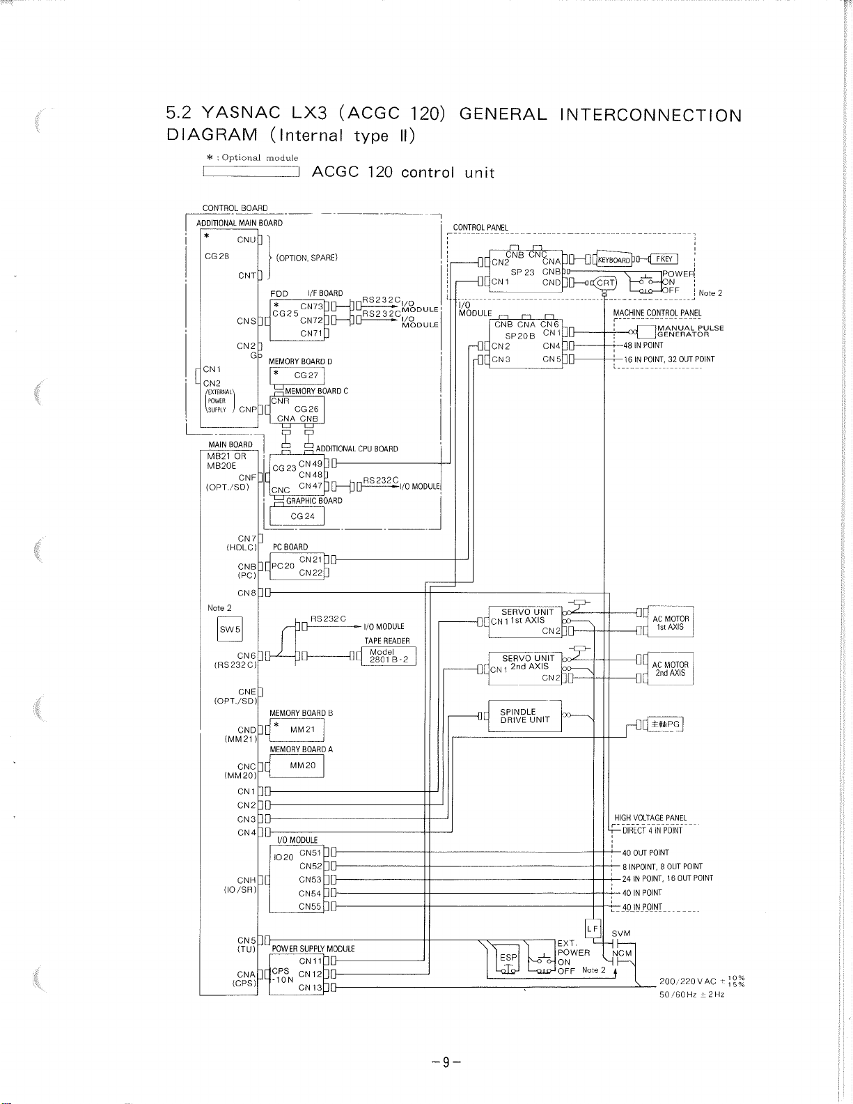
Page 9
!
YASNAC
:
DIAGRAM
Optional
:
*
CONTROL
BOARD
*
CG
28
1
CN
CN2
'EXTERNAL'
POWER
,
.SUPPLY
BOARD
MAIN
MB21
MB20E
(OPT./SD)
(HDLC)
Note
2
SW
(RS232C)
(OPT./SD)
(MM
(MM
(IO/SR)
(CPS)
MAIN
CNU
CNT]
CNS
CN
CNP
OR
CNF
CN
CNB
(PC)
CN8
5
CN6
CNE
CND
CNC
CN
CN
CN3
CN4
CNH
CN5
(TU)
CNA
ADDITIONAL
L
21
20)
5.2
(Internal
module
BOARD
'
]
•
(OPTION.
.
FDD
*
CG2
x
]
2
3
G
MEMORY
*
1
CNR
X
CNA
i
1
“i
CG
pn
CNC
]
7
PC
][
PC20
][K
]
MEMORY
1C*
)
MEMORY
X
1
2
I/O
IO
ii:
POWER
CPS
X
-10N
LX3
5
CG
'MEMORY
CG26
£
)
i
—
23
GRAPHIC
CG
BOARD
MM
MM
MODULE
20
(ACGC
ACGC
SPARE)
BOARD
l/F
cN73h[}—
][]
CN72
-
]
CN71
BOARD
D
27
C
BOARD
CNB
£
ADDITIONAL
i
i
—
-
CN49
JU
]
CN48
47
CN
(J
]
BOARD
24
HQ-
CN
21
]
CN22
RS232C
BOARD
B
21
A
BOARD
20
CN51
CN52
CN53
CN54
CN55
SUPPLY
MODULE
1
1
CN
CN
1
2
CN
1
3
type
ho
p0
CPU
p
Q
120
RS232C
RS232C
BOARD
RS
232
MODULE
I/O
TAPE
Model
2801
120)
II)
control
I/O
MODULE
I/O
MODULE
C
I/O
READER
B-2
MODULE
GENERAL
unit
CONTROL
PANEL
CNB
CN2
CN1
l
I/O
MODULE
CNB
SP20B
CN2
HX
CN3
HX
SERVO
Q[CN
1
SERVO
1
OCCN
SPINDLE
DRIVE
\\
ESP
-OLQ-1
SP
1st
2nd
23
i—i
CNA
CNC
AXIS
L-
INTERCONNECTION
30-OkEY
KEYBOARD
DD—OC
CNA
CNB
CND
CN
CN
CN4
CN
UNIT
CN2]Q
UNIT
AXIS
CN2]Q
UNIT
YOON
CLUHOFF
6
5
3D
]ÿ<CRT)
1
LF
T
EXT.
POWER
Note
_
_
_
POWER
\
_j
tÿJoN
MACHINE
CONTROL
r
HIGH
I—
—
X
4—24
—
X_4pJN_P0JNT
SVM
NCM
NK
2
A
POINT
IN
48
POINT,
IN
16
AC
1st
AC
2nd
VOLTAGE
•
VI
DIRYCT
POINT
OUT
40
INPOINT,
8
POINT,
IN
POINT
40
IN
MANUAL
GENERATOR
MOTOR
MOTOR
POINT"
N
8
200/220
50/60
32
AXIS
PANEL
OUT
16
l
FF
OUT
AXIS
OUT
!
PANEL
POINT
~
POINT
POINT
VAC
Hz
Note
PULSE
±2
2
'
.
i.
10%
t
5%
1
Hz
-9-
Page 10

•r
wrw&ijsggssw—
V
YASNAC
5.3
DIAGRAM
Optional
:
*
BOARD
MAIN
MB21
OR
MB20E
CNF
(OPT./SD)
CN
(HDLC)
CNB
tPC)
CN
2
Note
CN6
(RS232C)
CNE
(OPT./SD)
CND
(MM
21
CNC
20)
(MM
CN
CN
CN3
CN4
CNH
/SR)
(10
CN5
(TU)
CNA
(CPS)
module
CONTROL
MEMORY
*
CNR
CG23
X
CNC
7
PC
][
PC
8
]
MEMORY
][*
)
MEMORY
X
1
2
]ÿ
ADDITIONAL
][
POWER
CPS
J[
-
MX3
(Internal
ACGC
BOARD
BOARD
CG
27
MEMORY
BOARD
CG
26
CNA
CNB
LYI
£ £
SP21
0
1
CN49
CN48
CN47
GRAPHIC
CG24
BOARD
CN
20
CN
RS232C
BOARD
MM
21
BOARD
20
MM
CN
CN62
CN63
CN64
CN65
CN66
SUPPLY
CN
CN
N
CN
Note
ADDITIONAL
BOARD
21
22
AXIS
61
1
1
2
1
3
1
(ACGC
D
C
1
J
]Q—
DD
I/O
B
A
BOARD
MODULE
type
CPU
RS232C
MODULE
TAPE
Model
2801
120
BOARD
READER
B-2
120)
I)
control
MODULE
I/O
GENERAL
unit
CONTROL
PANEL
i.
I/O
MODULE
r-QC
r0[
[CNllst
[|[CN
{][
~Q[CN1
-[][
CNB
CN2
SP23
1
ON
CNB
SP20B
CN2
CN3
[
H][
rOC
XC
DU
—
DC
SERVO
SERVO
2nd
1
SERVO
1
CN
SPINDLE
DRIVE
*
SERVO
4th
SERVO
*
5th
1
CN
ESP
UiJ
CNC
CNA
MODULE
I/O
CN1
1
CN
1021
CN
13
CN1
MODULE
I/O
CN12
CN1
1021
CN1
CN11CN6
UNIT
AXIS
AXIS
AXIS
3rd
UNIT
AXIS
AXIS
s-°
—
INTERCONNECTION
48
IN
“16
IN
40
IN
8
24
40
40
4
OUT
40
8
IN
24
40
40
4
OUT
DIRECT
I
—
NCM
I
F
0
d
—
o
CONTROL
POINT
P0I0T,
OUT
POINT
POINT,
POINT,
IN
IN
POINT
POINT
IN
POINT
OUT
POINT
POINT,
POINT,
IN
IN
POINT
POINT
IN
POINT
4
AC
AC
AC
SPINDLE
DMPG
Of
AC
Of
AC
1
Q[
CNA
CNE
CND
CN
6
CN
1
CN4
5
CN
1
CN
2
4
2
CN
CN3
CN4
CN5
1
6
CN
1
CN
4
CN2
CN3
CN4
5
3
CN
CN
2
UNIT
CN2]Q
UNIT
CN
2
UNIT
CN2]Q
UNIT
CN2]0
EXT.
POWER
°-
ON
QJ_Q-*0FF
-
HO
]Q
—
]Q
]Q
oo
-
fir
00(CRT
Note
KEYBOARD)]
MACHINE
HIGHVOLTAGE
I
\
SVM
2
KEY
POWER
ON
OFF
PANEL
MANUAL
GENERATER
OUT
32
PANEL
POINT
OUT
8
OUT
16
(READ
OUT
POINT
8
OUT
16
(READ
POINT
IN
MOTOR
AXIS
1st
MOTOR
AXIS
2nd
MOTOR
AXIS
3rd
MOTOR
AXIS
4th
MOTOR
AXIS
5th
200/220
Hz
50/60
i
Note
PULSE
POINT
POINT
RELAY)
POINT
RELAY)
VAC
±2Hz
I
I
2
/
1
i
ft]
I
I
;
10%
+
-
5%
1
-10-
Page 11

1
%
ACGC
SPARE)
(ACGC
type
120
YASNAC
£
5.4
DIAGRAM
Optional
:
*
CONTROL
BOARD
ADDITIONAL
CG
MAIN
BOARD
]
CNU
28
MX3
(Internal
module
]
'
(OPTION.
CNT]
FDD
*
CG2
][
CN
S
]
CN
2
3
G
,
CNP
BOARD
OR
CNF
SD)
CN7
(HDLC)
CNB
(PC)
CN
2
CN
CNE
CND
CNC
20)
MM
CN
CN
CN
CN4]Q
CNH
/SR)
CN5
(TU)
CNA
(CPS)
MEMORY
*
CNR
X
CNA
CG
on
CNC
[ÿGRAPHIC
]
PC
][
PC20
8
6
]
MEMORY
][*
MEMORY
X
1
2
][}
3
ADDITIONAL
SP21
JL
POWER
CPS
J[
-
1
CN
1
D
CN2
'EXTERNAL'
POWER
.SUPPLY
MAIN
MB21
MB20E
(OPT.
Note
SW5
(RS232C)
,KV
(OPT./SD)
(MM21)
(
(10
l/F
CN73hD
5
CN72
CN7
BOARD
CG
27
MEMORY
CG26
CNB
£
£
CN49
23
CN48
CN47
CG24
BOARD
CN
CN
RS232C
BOARD
MM
21
BOARD
MM
20
CN61
CN62
CN63
CN
64
CN
CN66
SUPPLY
CN
CN
0
N
CN
BOARD
hQ
-
-
PQ
3D
]
1
D
C
BOARD
1
Note
ADDITIONAL
]
OQ
ID—
BOARD
}
21
}
22
B
A
BOARD
AXIS
65
MODULE
11
2
1
3
1
RS232C
RS232C
CPU
RS232C
MODULE
I/O
TAPE
Model
2801
BOARD
II)
control
I/O
I/O
I/O
READER
B-2
120)
MODULE
MODULE
MODULE
GENERAL
unit
PANEL
CONTROL
2
CN
1
CN
i
—
CNB
SP20B
CN2
rOC
CN
3
rOC
DC
oc
I—
rOC
4J[
L-0[
r-OC
SERVO
Q[CN1
SERVO
Q[CN1
SERVO
1
CN
SPINDLE
DC
0[CN1
—
[
—
CN
*
*
DRIVE
SERVO
SERVO
1
ESP
oi-T
—
—
CNB
SP23
i
1st
2nd
3rd
4th
5th
CNC
CNA
MODULE
I/O
CN
1
2
1
CN
1021
CN
1
1
CN
MODULE
I/O
CN12
CN14
1021
CN13
CN1
UNIT
AXIS
AXIS
UNIT
AXIS
UNIT
AXIS
AXIS
Y)
—
INTERCONNECTION
CNA
CNE
CND
CN
CN
CN4
CN
CN
4
CN
CN3
CN
CN5
3
1
CN
CN
CN2
CN3
CN4
CN
1
CN6
CN2
UNIT
CN2]Q
CN2]Q
UNIT
CN2]D
UNIT
CN
QI.Q~ÿ
6
1
5
1
2
4
6
1
5
2
o-ON
OFF
]0
[[KEYBOARD)]
—
4.
L
:
f-
f-
f-
+
]Q
][}
LF
Note
SVM
NK
2
|
EXT
POWER
D-RT
CONTROL
MACHINE
POINT
48
IN
POINT,
IN
16
HIGH
VOITAGE
40
OUT
POINT,
8
IN
POINT,
IN
24
40
IN
POINT
IN
POINT
40
4
OUT
OUT
40
POINT,
IN
8
POINT,
IN
24
POINT
40
IN
POINT
IN
40
OUT
POINT
4
DIRECT
Dq
I
—
or
{][
on*
NCM
F
MANUAL
GENERATOR
POINT
POINT
POINT
4
IN
AC
1st
AC
2nd
AC
3rd
SPINDLEI
PG
AC
4th
AC
KEY~1
POWER
ON
OFF
PANEL
OUT
32
PANEL
OUT
8
OUT
16
(READ
POINT
OUT
8
OUT
16
(READ
POINT
MOTOR
AXIS
MOTOR
AXIS
MOTOR
AXIS
MOTOR
AXIS
MOTOR
AXIS
5th
200/220
50/60
Note
PULSE
POIOT
POINT
RELAY)
POINT
RELAY)
VAC
Hz
±2Hz
2
+
—
I
!
:
!
E
:
:•
:
I
I!
I
K
1
1
:
f
t
:
I
:
0%
1
5%
1
i
l
-11
:
-
Page 12

::r
w.-wasw"’"
S82S33®®«ffl
5.5
JANCD-CG
SYSTEM
SWITCH
i
Note
CN49
MRP-20F01
MR-20L
;
CN47
7
SD
6
RD
RS
5
4
CS
3
DTR
2
DSR
SG(OV)
1
ACGC
23(DTN5580)
NUMBER
SW1
i)
8
£oi
CONNECTOR
VSYNC
VSYNCHSYNC-15
HSYNC
POFF
PCOM-3
*
*
7777
CN
48
1
KSD
2
15V
3
V
5
I
4
OV
5
0V
6
0V
CONNECTOR
13I
19
12
18
11
17
10
16
(RST)
9
15
(0V)
14
120
CN
VDRVDR
VDG-11
VDG-
VDB-9
VDB-8
PON-
KRD-4
KRD-5
KSD-6
KSD-7
OV-1
V
0
FG
CN
CN
TABLE
FG
49
-
),
7
1
16)
4
4
-
1
4
4
13
4
-
1
2)
4
4
10
4
j
4
4
18
4
-
9
1
4
4
4
4
4
4
*
-
2
J
)
-
20
Note
FULL
48
(SUPPORTING
USER
1
CONNECTOR
47
MRP-20F01
J
MR-20L
(MANUFACTURED
CABLE
CABLE
LENGTH
TP
IE
IE
IE
IE
IE
IE
Note
3
77/7"
4
KEYBOARD
ONLY
CPS-
1
OR
10
21
RS-232C
CONNECTION
Max.
15m
JCN2-17
J
<
J-14
j-13
<*
«T9
(
<*
<*
J
;)
:•
<4-4
«
<<
4
V
5
TSUSHIN)
CONNECTOR
DEVICE)
«
<f4-+
<<
«
CONNECTOR
DEBUG
THE
+
0N
0
12V
+
BY
HONDA
AC
200/220
50/60
W
1
60
JANCD-SP23-1
1
R
2
G
3
4
5
B
6
7
E1W
8
9
10
11
12
13
14
15
H-
SYNC
16
V.
17
SYNC
18
19
2Q|FG
-
1
6
15
:
'
-
1
1
-
0
1
-8
-18
19
-
-3
-5
6
ov
1
-2
2
20
3
FG
4
CNA
TABLE
i
1
CN
-
1
5V
+
4
0
sv
V
2
1
I
CONNECTOR
CNB
13
6
121W
5
11
4
10
3
9
mi
2
8
3ETTJ
1
1
+-
V
-15%
Hz
±1%
Max.
(DTN5910)
OV
OV
OV
OV
OV
OV
OV
LEVEL
CON-
VERIER
MPU
o
o
o
Keyboard
o
o
o
Select
o
o
o
SW
ABC
BZR0
2
3
CETSO
4
5
LED2
6
8
LED4
FG
10
it
0V
12
13
14
0V
16
0V
16
17
DK0
18
'9
20
DK2
21
22
DK4
23
24
OK6
25
26
SELO
27
SEL2
28
29
SLL4
30
30
32
SEL6
33
34
SEL8
35
36
SEL10
37
SEL1238SEL13
39
SEL14
40
TABLE
20
m
19
18
17
16
“SETS
15
14
0
'
DIAGRAM
AC
CONNECTOR
1-48700-0
(AMP)
R
%
S
FLAT
CND
CNC
-10
m
•8
-9
-
1
2
1
-17
-18
ov
CNE-21
PON
1
-
>
-3(;PCOM
ROM
fesl
27256
BZR1
LED1
LED3
LED5
FG
+6V
5V
+
5V
+
DK1
OK3
DK5
DK7
SEL1
SEL3
SEL5
SEL7
SEL9
SEL11
SEU5
FG
DZR1
DZR0
DR7‘
TO”
EE3T
W
CNB
CNA
i
FLAT
(40-CORE)
Note
DETACHED
KEYBOARD
(1/2)
POWER
SUPPLY
«
<<
1
CABLE
(20-CORE)
VIOEO
PRINTER
(SUPPORTING
CNE
CONNECTOR
VHR-3N
(MANUFACTURED
POWER
QXJT-GREEN(SW784)
o
-
1
QXJT-RED(SW785)
1
-ole
-
FLAT
(10-CORE)
UL
CABLE
CNA
5
TX1424AD(CRT
INPUT
AC
FUSE(4A,
-1
-2
-3
IN
CONNECTOR
SIG.
7
Note
BRIGHTNESS
VR.
¥
IN
SIG.
ONLY)
l/F(SP23-2
ONLY
BY
JANCD-SP24(DTW5930)
CABLE
CNE
GNJR||
UNIT)
DEBUG
THE
ACCHAKU-TANSHI
NIPPON
ON/OFF
SOFT
CONNECTOR
1
£iK0
[2|~5ET8
3
4
DKT
T5KT
5
6
7
DK3
8
WJ
1C
9
|
1
BZRO
2IBZR1
4
LEDO
3
5
6
7
8
9
1
121
r.i
1
141
1
19
;
1
1
2i
2;
2
DRT
i]
23
DK6
24
2‘
21
2;
2‘
2
3i
3;
311
33*5‘EL8
34JSEL9
1
3
31
4
13)
250V)
1
R
2
4
G
3
B
5
6
7
HTYN7:.
8
73YNCI0
9
12
14
13
16
15
17
18
19
20
SW.
<EY
UNIT
TABLE
T£iT
~WT
DK6
DK5ÿ
-ÿ
BUZZER
EFB-RC24201
o
+5V
+5V
+5V
DK7
CRT
TABLE
0V
0V
0V
ov
OV
FG
)
#-
i
I
f:
I
%
%
*
%
£
I
i
-12-
S'
s
8
I
1
1
.
Page 13

1
*
!
ACGC
5.5
JANCD-CG28
CNS
<
CABLE
120
JANCD-CG25(DTN5600)
BOARD
OPTION
i
CNS
CN
72,
7
6
5
4
3
2
1
CONNECTION
CN
73,
CONNECTOR
SD
13
RD
RS
CS
DTR
DSR
SG(OV)
20
12
19
1
18
1
17
10
9
16
8
15
14
TABLE
FG
DIAGRAM
USER
CN
72
73
MRP-20F01
MR-20L
HONDA
USER
1
MRP-20F01
MR-20L
HONDA
J
CN
(2/2)
RS-232C
CONNECTOR
(MANUFACTURED
TSUSHIN)
RS-232C
CONNECTOR
(MANUFACTURED
TSUSHIN)
BY
BY
!
f
CN
71
i
i
FDD
(SUPPOTING
CONNECTOR
l/F
ONLY
THE
DEBUG
DEVICE)
:
l
.
:
I
!
i
CN
7
1
1
3
5
7
9
11
13
15
17
19
21
23
25
27
29
31
33
CONNECTOR
Signal
Pin
ov
0V
OV
OV
OV
OV
OV
OV
OV
OV
OV
OV
OV
OV
OV
OV
OV
Number
2
4
6
8
10
12
14
16
18
20
22
24
26
28
30
32
34
TABLE
Name
Signal
/LSP
/HOLD
/DRIVES
/INDEX
DRIVEO
DRIVE1
DRIVE2
MOTOR
ON
/DIR
/STEP
/WDATA
/WGATE
,/TRACKO
WRPROT
,/RDDATA
/SIDESEL
READY
13~
;
!
!
I
i
:
I
i
:
i
M
I
;
Page 14

[CONNECTORS]
•
List
of
CPU
Module
JANCD-CG23
•
List
of
CRT
Panel
JANCD-SP23
CRT
CPU
Name
Panel
Name
unit
Module
Connector
No.
CNA
CNB
CN47
CN48
CN49
Connectors
Connector
No.
CNA
CNB
CNC
CND
CNE
CN1
CN2
Power
supply
Signal
Connectors
Connector
FRC2-C50L12-OL
FRC2-C50L12-OL
MR-20RMA
TM5RA-66
MR-20RMA
Connector
FRC2-C40L12-OL
MR-20RFA
MR-20RFA
FRC2-C20L12-OL
B3PS-VH
172040-1
MR-20RMA
1-480701-0
FRC2-C20L12-OL
Board
Board
Side
Name
Side
Name
Cable
Connector
Connected
Connected
MRP-20F01
Free
MRP-20F01
Cable
Connector
Connected
Free
Free
Connected
Connected
172026-1
MRP-20F01
1-480700-0
Connected
Side
Name
Side
Name
I
5
[RS-232C
JANCD-CG23
Interface]
MODULE
CPU
CN47-7
4f
3
1
I
V
3
RO
-i
SD
RD
RS
CS
DR
ER
T
SG
FG
-4"
3
T4
4-
4
I
2
5
7
1
-14-
RS-232C
FOR
ACGC
INTERFACE
I
fy
Page 15

I
c
(
5.6
Note
Note
NOTES
1
O
4
o
7
lo
10
o
(Preset
1
Connect
as
2
The
OFF
selection
circuit
(basic)
SW
5
o
ol
at
the
ON
follows.
power
(POF)
3
6
o
9
o
12—
factory
between
CG23
can
plug
or
14"
-
-“For
EOF
—
prior
THE
MODULE
be
can
or
the
be
SW
CRT
14"
CRT/9"
system
the
(disable/
(disable/enable)
shipment)
to
CONNECTION
CG23
FLAT
supplied
done
5.
CRT
(operation
enable)
CABLE
external
The
(optional)
and
on
hold)
the
SW
CG26
CG
or
5
DIAGRAMS
modules
CONNECTOR
w
mm
MODULE
26
disconnected
power
.
main
also
SW
ON
allows
5
card
1
4
7
10
with
/OFF
Use
To
Panel
ooo
ooo
o
lo
two
by
the
(EOF).
(MB
21
selection
Setting
Only
(POF)
3
6
9
o
10
12
ol
50-core
panel
or
of
To
External
1
o
4
o
i
o
lo
of
Use
SW5
o
o
o]
The
MB
the
Only
(EOF)
o
o
o
flat
power
2
OE
3
1
6
4
9
7
10
12
cables,
ON/
following
)
short
"
CRT
9
Use
To
Both
o
o
o
ooo
[c/ol
o
o
fcTol
12
;
:
'
\
3
6
9
Note
3
Always
SW5
Make
open.
sure
set
Nos.
that
4
and
the
6
of
shield
line
of
the
signal
cable
is
treated
as
fol¬
lows.
(l)
When
the
connection
In
of
the
cable
the
grounding
prevents
to
This
connect
NDING
GROU
PLATE
control
this
the
fO
c
diagram
case,
and
external
outer
/CABLE
OUTER
COVER
CABLE
/
CLAMP
panel
shows
always
clamp
plate.
shielding
CABLE
HIELDING
S
and
the
noise
the
this
use
cable
cover
NC
separated
the
so
from
to
OUTER
SHIELDING
COVER
control
shielded
that
flowing
CN2-20
the
CABLE
unit
case)
the
cable.
shielding
into
pin
4-
are
the
CABLE
separated
Strip
cover
control
of
the
GROUNDING
CLAMP
the
SP23
PLATE
(the
outer
grounded
is
unit.
module.
cable
cover
Also
\
(
-15-
Page 16

5.6
(2)
NOTES
When
ture
the
ON
control
THE
CONNECTION
panel
and
the
DIAGRAMS
NC
control
unit
(Cont'd)
are
of
integrated
struc¬
(a)
When
Generally,
in
but
the
(the
wiring
this
Also,
cable
end
Though
connection
noise
test.
JANCD-CG23
CN-49
VSYNC
VSYNC
1
ov
ov
FG
rb
path
-17J,
-16),
-1
-%
To!
using
follow
case,
clamp
at
to
I
j
T
use
the
the
or
improve
the
cable
method
always
shielded
as
CPU
above
configuration
the
in
module
the
(l).
perform
cable
(l).
wherever
Connect
side)
single-end
noise
JANCD-SP23
|CN2
-17
L
Tie
r
4bL
FG
>20
L
The
a
noise
with
connection
of
resistance.
A
following
test.
possible.
one
the
the
control
simple
end
of
pin
FG
is
Evaluate
Simple
In
an
cabinet
external
that
the
feed
drive
within
I/O
cable
cable
NC
the
But
the
on
be
to
unit
method
integrated
acts
noise.
affect
servo
unit
the
cable
,
and
that
unit.
way
there
outer
the
basically
may
the
as
the
,
magnetic
NC
,
are
can
also
is
no
shielding
connector.
require
connection
structure
shield
a
The
signal
drive
unit,
unit
servo
AC
/
power
connected
be
need
applied,
a
noise
cable
relay
,
spindle
used,
to
cover
two-end
with
,
against
sources
spindle
and
supply
outside
use
the
a
the
are
unit
the
PG
When
be
power
Also,
(b)
using
careful
cable
always
When
Connection
distance
the
cable
cannot
*
Use
•
Keep
become
uate
•
Treat
•
Always
of
using
with
single
the
the
cables
the
that
perform
single
between
be
1/
the
noise
the
twisted
perform
without
binding.
can
single
used,
lines
O
source
become
evaluation
lines
lines
CG2
the
use
0.3mm2
of
cable,
of
by
performing
pair
noise
shielding,
Keep
the
generally
is
3
single
a
PG
cable
noise
lines
test
the
source
with
and
line,
or
above.
separated
noise
with
to
evaluate
no
I/O
a
SP23
of
care.
special
cable,
of
noise
not
taking
the
test.
ing
method,
prevent
to
noise
test.
allowed.
modules
care
servo,
from
the
noise.
wiring
The
etc.
this
connection
PG
cable
separated
However,
is
short
of
the
AC
power
each
other.
path,
can
noise
required,
is
of
the
from
and
following.
cable
Always
line
bind¬
arranged
be
interference.
servo,
each
only
shielded
a
other.
when
that
eval¬
but
AC
can
f.
-16-
Page 17

Note
4
The
not
Do
full
keyboard
use
full
provided
is
keyboards
other
only
than
for
specified
the
debug
unit.
by
YASKAWA.
Note
Full
5
The
and
operating
board
within
the
Example
DETACHED
keyboard
detached
detached
box,
The
3
standard
4
1
D
KEYBOARD
the
function
m
from
1
"CRT
BOX
model
keyboard
to
keyboard
permit
to
vertical
*7
B5GS-C098-406
from
the
key
is
SP23
the
keyboard,
CABLE(20-C0RE)
Max.
3
m
used
function
control
for
some
operation
as
module.
(manufactured
allows
panel.
time,
while
follows.
The
is
offered
Example
the
This
to
establish
sitting.
The
detached
as
4"CRT
1
keyboard
function
cable
keyboard
option.
an
2
OMRON)
by
to
is
a
detached
length
THE
CRT
PANEL
MADE
COMPACT.
CABLE(20-CORE)
Max.
3m
be
used
box,
attached
is
CA
N
BE
when
key¬
to
using
be
Note
6
Select
corresponding
the
the
standard
representative
In
this
refer
JANCD-SP23
_
I
ll
to
_
the
case,
keyboard
Par.
I
L
If
vertical
when
our
9.2
for
select
keyboard.
and
specialized
a
system
details
SW1
switch
The
horizontal
software
on
SW1
following
keyboards.
keyboard
development
the
OEMs.
short-circuit
is
the
produced
is
will
(Four
SW1
l
olo
2
lo
olo
|o
3
olo
4
0
00
ABC
1
lo
olo
o[o~o1
2
3
lo
olo
4
0
0 0
ABC
Contact
A,
ol
Set
standard
(The
sideofthe
Set
standard
(The
sideofthe
plug,
method
required.
be
B,
and
keyboard
the
keyboard
keyboard
the
keyboard
according
for
your
by
the
Cs
are
vertical
CRT)
horizontal
CRT)
setting
Yaskawa
OEM.
not
of
the
CRT
is
the
at
the
of
CRT
isatthe
to
Also
used)
unit.
lower
unit.
right
-17-
Page 18

5.6
Note
NOTES
7
A
The
follows.
AC
setting
fore
the
and
100V
ON
left
power
supplying
switch
lower
side
THE
rear
side
100V/220V
always
up,
set
set
normally
is
CONNECTION
of
the
14"
selection
the
the
at
screws
check
power.
10
can
not
that
0V
used.
DIAGRAMS
color
switch
the
If
200
side,
be
loosened
CRT.
switch
VAC
the
for
is
or
CRT
to
(Cont'd)
Sections
the
14"
set
higher
will
change
at
A
color
the
is
connected
fail.
the
to
CRT.
220V
The
setting.
D
are
side
f
as
When
be¬
with
upjjer
The
SP
the
adjustment
unnecessarily
at
not
CRT
OFF
stand-by
the
connector
to
70W)
connector
module
3
2
Video
variable
value
under
viewing
key
on
mode
CRT.
select
200/220V
type
at
Press
100V
the
no
brightness
CRT.
depress
the
the
power
for
max.
where
connected.
are
adjustment
standard
further
When
the
CRT
the
in
life
of
input
method
specifications
(typ.
input
B
Connector
(20-core)
C
CRT
sted
needs
the
of
plied,
to
prolong
the
D
The
above
AC
brightness
at
CRT
the
set
CRT.
AC
power
100W
power
AC
CND
signal
input
resistor.
factory
the
normal
high
CRT
the
keyboard
the
(the
CRT
the
for
the
or
+10%
1-480700-0
connector
value
key
1
220V
while
turns
4
-15%,
and
connector.
The
resistor
before
circumstances.
will
shorten
power
the
(standard
black)
color
power.
more
CRT.
once
"
AC
50/60Hz
(AMP
Co.)
flat
delivery
keyboard)
which
to
3-pin
cable
adju¬
is
and
Setting
the
sup-
is
can
activate
See
±1%,
lock
A
life
A
connector.
A
SP
MODULE
23
,
AC
(
t
c:
LSIG,
.r.
M
SELECT
V
100
V
220
4-
B
IN
4>
I
BRIGHT
*
j-r-,
4
1
D
I
I
-18
Page 19

8
Note
(l)
The
Keep
the
no
other
the
machine
setting
than
function
(2)
The
Keep
the
developing
must
tion
system
the
Also
check
system
(3)
System
mode.
The
end
or
the
The
switch
to
0
number
the
end
system
is
does
machine
system
be
to
the
user
system
operation
are
can
E
switch)
following
user
number
tool
necessary
may
0
not
application
the
made
number
that
end
number
or
will
as
follows.
set
be
at
when
switch
manufacturer
by
cause
work
tool
the
during
manufacturer
number
with
the
switch
system
the
users.
switch
machine
fail.
modes
with
the
setting.
the
system
switch
software.
system
0
to
number
settings
tool
for
rotary
the
upper
fixed
with
user.
right
at
the
Starting
to
operation.
fixed
However,
number
after
setting
switch
5
to
manufacturer
setting
the
0.
fail.
at
E
switch
corner
The
system
0,
are
on
SW
the
Also
as
parameter
switch
and
is
set
for
should
the
1
or
switch
number
machine
note
with
set
changing
at
Yaskawa's
never
ACGC
(hereafter
CG23
the
will
be
switch
with
the
that
the
end
setting
1.
at
before
0
use
120
delivered
the
self
users,
Always
the
system
these
system
called
system
module.
set
at
setting
diagnosis
and
altera¬
return
parameters.
shipping
diagnosis
settings
number
from
0
if
Note
,
so
at
not
the
Setting,
System
Specifications
CD
The
(
immediately
(2)
The
display
The
(3)
The
execute
(4)
This
index
tion
the
is
It
program
Note
utility
Multiple
Number
Application
Mode
When
When
the
system
the
system
the
development
When
the
system
the
When
specifications.
the
mode
"1"
program
necessary
not
replacement
that
and
is
is
the
dividing
files
Internal
All
GMISC
Execution
system
starts
up,
execute
system
starts
application
up,
mode
system
starts
application
system
basically
immediately
not
be
can
file
name
cannot
0
type
commands
can
number
synchronizing
the
number
synchronizing
program
screen
number
up
in
program
number
equivalent
replaced
input
to
under
file,
the
exist
on
1
Debug
unit
and
be
used.
Development
switch
application
switch
is
switch
ACGC
switch
executed
the
these
created
cannot
on
a
System
the
Portable
Commands
GMISC
be
used.
Execution
is
with
program
is
with
development
equivalent
is
unit,
(index
is
to
the
by
the
alphabet
specifications.
when
be
single
Number
2
type
related
set
at
at
set
at
set
power
as
"1"
set
at
system
as
power
floppy
merging
changed.
diskette.
3
NCREQ,
to
Execution
0
NC,
the
(index
1
NC,
the
mode
to
the
2
).
3
disk
key
Switch
FREQ
the
existing
is
number
supplied,
is
drive.
on
is
executed
4
and
NC
cannot
Development
power
as
).
"1"
power
as
screen.
supplied,
switch
the
screen
Program
the
createdbythe
sational
be
Yaskawa's
is
is
screen.
to
and
The
by
-
5
Do
not
and
prog:
destroyed.
system
supplied,
supplied,
immediately
mode,
2
the
following
application
of
EXE.MRG
the
E
touch
data
conver-
ram
diagnosis
but
applica¬
are-
will
to
to
-19-
Page 20

*'!
'
SETTING
6.
SWITCHES
OEM
The
(1)
JANCD-CG26/CG27
Switch
(Also
see
SW2
Section
SW1
should
Name
8.)
THE
refer
MODULE
Par.
to
module
Enables/disables
to
or
the
the
setting
the
VPP
factory
the
SW2
module
replace
when
stand-alone
short-circuit
on
by
CG26/CG27
set
this
side
supplied
is
on
the
setting
necessary
Used
module,
unit
Set
on
The
necessary
Sets
Always
The
power
If
mounted
The
normally
is
9.2.
the
the
application
(ROM
delivery
the
machine
switch
8)
(5
to
module
SHORT-CIRCUIT
Descriptions
ROM
ROM
PROHIBIT
modules
is
with
on
type
plug
is
at
used
the
will
delivery
by
the
mounted
memory
software
at
at
at
the
manufacturer
tool
at
the
NORMAL
for
setting
be
machine
on
space
is
OEM.
the
the
status)
side.
EN
online
factory
at
destroyed.
is
the
at
the
to
developed
side,
DIS
.
No
mode
side
maintenance
the
NORMAL
manufacturer
tool
PLUG
CG26/CG27
on
using
disable
end
offline
side,
the
is
user.
mode)
(offline
side.
RAM
to
change
or
or
(offline
VPP
Enable:
Disable:
modules.
CG29
the
normally
mode.
the
No
or
debug
the
1
mode).
ROM
end
EN
DIS
ROM
to
change
user.
%
4.
V
The
CNP
t
0 0
0
Arty
5
CD
SIS
SW2s
JANCG-CG26
CNA
l
CO
0.
0
r-
o
Z>
CD
a
in
CO
<
CM
g
Z
in
CNR
the
[
CNB
]
CM
5f°lb
above
o
]
O'*
Q
SW
SW
figures
JANCD-CG27
2
1
3
CD
are
ts3
o
u
i-Lfl.
0
a
CO
r-.
CD
in
co
CM
both
CNR
Q.
Z>
<
o
]
D
0
D
ENVOIS
INHIBIT
ROM
set
at
NOT
the
SW
SW
1
2
USED
EN
(enable)
A
side.
-20-
0
Page 21

(2)
JANCD-CG29
module
Switch
(Rotary
(Also
SW2,
see
Name
3
switch)
Section
8.)
o
2
MB
can
set
This
the
of
cation
SW2
the
o
8
SW
2
S-RAM
set
be
the
module
and
instructions
in
address.
CG26
software
3
oh
is
and
can
is
1
'8
SW
MB
used
select
is
o
mounted
unit
at
CG27
using
Par.
3
on
in
the
modules
debug
the
0
to
9.2.
]
SW2
SW3
Description
the
this
OEM
F,
but
Example
CG29
S-RAM,
replace
to
RAM,
to
unit
setting
400000
C00000
module.
or
and
when
the
must
to
to
The
SW2
ROM
the
developing
portable
be
the
In
4FFFFF
CFFFFF
and
done
left
memory
3
are
memory
type.
according
figure:
the
address
used
space
appli¬
to
to
l
(3)
JANCD-SP23
A
short-circuit
the
Par.
DC
9.2
power
for
“DOTCLK"
pin
the
B
(4)
at
between
the
JANCD-MB21
Short-circuit
CN4
connector
details.
factory
module
plug
connector
1
before
DOTCLK
1
lo~~ol
2
o o
3
o
<1
o
plug
side
switch
printed
is
and
o
o
o
o
o
o
ABC
or
MB20E
switches
of
both
with
CN1
A,
B
delivery.)
module
with
modules.
side
on
as
"
KEYBOARD
of
this
the
CNC
shown
below.
“SW5"
See
module.
connector
printed
Par.
"
printed
(The
on
6.6,
See
pin
them
and
side
on
Par.
will
Note
of
are
it
is
6.6,
the
be
set
mounted
2
for
mounted
Note
SP23-02.
at
1
details.
on
on
and
6
Set
A,
-
1
the
-21
:
-
Page 22

KJjJV®
MEMORY
7.
Module
JANCD-CG23
JANCD-CG24
JANCD-CG26
JANCD-CG27
JANCD-CG29
application
The
super
capacitor.
charged,
power
the
If
the
stored
that
backup,
for
are
Note
CPU
Graphic
Y-E
Application
Application
Application
Application
Debug
and
off
by
the
Description
Module
character
RAM
then
period
the
data
SPACE
module
ROM
RAM
ROM
RAM
RAM
and
super
The
after
is
and
the
super
on
the
ROM
debug
capacitors
short
a
single
a
battery
capacitor
CG26
Capacity
System
System
2M/1
RAM
period,
day,
is
even
are
RAM
ROM
128k
64k
1.25M
512k
1.75M
512k
are
not
stored
352K
512K
disk
on
the
the
run
when
Can
backed
cards
battery
super
down.
the
by
the
Address
000000
080000
100000
800000
240000
880000
100000
900000
be
up
other
cards
battery.
-057FFF
-0FFFFF
-23FFFF
-87FFFFF
-3FFFFF
-8FFFFF
-7FFFFF
-FFFFFF
specified
by
also
capacitor
The
are
the
than
starts
data
Application
YASKAWA’S
YASKAWA’S
CRT
Application
Application
Application
Application
Debug
application
within
battery
CG2
to
alone
on
removed.
system
system
Application
of
the
range
this
and
are
6
discharge.
enough
is
the
cards
the
dis¬
w
I
Address
000000
100000
200000
300000
400000
500000
600000
700000
800000
900000
0000
A
00000
B
00000
C
0000
D
0000
E
00000
F
FFFFFF
(T)The
but
ROM
CG23
CG26/CG27
Settable
(but
Currently
Currently
Currently
CG26/CG27
Currently
0
Currently
Currently
Currently
0
Currently
0
Currently
Currently
range
the
INHIBIT.
RAM/ROM
ROM
currently
Prohibited
Prohibited
Prohibited
RAM
Prohibited
Prohibited
Prohibited
Prohibited
Prohibited
Prohibited
Prohibited
of
RAM
used)
not
100000
CG29
of
Also
CG29
CG29
CG29
RAM
RAM
RAM
to
can
see
3FFFFF
be
Section
©
is
assigned
7
SW2
ISW3
normally
by
(l)
and
000000
057FFF
080000
0FFFFF
100000
2
3FFFF
240000
3FFFFF
800000
7FFFF
8
880000
8FFFFF
0
0 0
X
XFFFFF
Y00000
YFFFFF
setting
Par.
0 0
the
X
Y
—
=
ROM
the
9.2.
System
System
Application
Application
Application
Application
Application
Application
7,9
to
to
1
7,9
to
to
1
SW2
RAM
ROM
F
F
of
ROM
ROM
RAM
RAM
RAM
RAM
CG26
of
(352
(512
(1.25
(1.75
(512
(512
(1
(1
CG26,
K)
CG23
K)
M)
CG26
M)
CG27
K)
CG26
K)
CG27
M)
M)
and
CG29
CG27,
CG27
at
f.
--
©The
and
physical
CG29.
of
3
address
Also
see
X,
Y
can
Section
be
7
(2)
-22-
specified
and
Par.
optionally
9.2.
by
selecting
SW
2
Page 23

PRESHIPMENT
%
8.
8.1
SYSTEM
GENERATION
SETTINGS
(INITIAL
SETTING)
i
application
replaced
connection
i!
CD
*-«
J-
PH
7
"a
£
o
CD
a.)
-
'P
cp
CP
OO
0-
5
£
•5
£
g
ID
“1
£
g
CD
:,i
>
'M
13
CD
2
£
Aj
O
©
S-c
Ill
If
the
at
Set
the
setting
Set
the
(Stand-alone
1)
Turn
2)
Depress
3)
Depress
4)
Set
Example
5)
Depress
6)
Set
Example
7)
Depress
screen)
1)
Depress
2)
Depress
3)
Depress
4)
Set
value
5)
Depress
6)
Turn
l)
Turn
2)
Depress
3)
Depress
4)
Depress
5)
Depress
6)
Turn
CG23
Set
(development
l)
Turn
2)
Depress
display
1)
Turn
2)
Return
The
the
check
switches
method
CG23
on
the
date
the
time.
.
parameter
the
of
off
on
off
system
on
the
off
the
above
TIME
EXIT
GEN
Y
<F4>
When
is
NC
Item
Switch
Setting
A
"3
o
-g
f
I
o
XI
'$
g
OvJ
<Dÿ
3
P
£
<io
software
machine
after
and
Operation
on
each
of
each
system
development
the
<F6>
DATE
May
—
2:24:00
—
<F5>
(or
Y
each
<F9>
the
the
<F3>
<F2>
<F3>
(or
the
power.
NC
power.
CG23
completes
power.
to
(FI).
880526
(F2)
142400
(F9)
to
(FI).
YES
OEM.
to
power.
power.
for
for
for
YES
power
number
mode)
to
screen.
number
set
26,
.
p.m.
set
according
write
system
ROM
tool
care
module
OEM.
mode)
the
1988
WR>
<
WR>
<
(to
return
the
(F2)).
(See
Table
the
operaion.
file
generation.
files.
all
<F1>],
switch
.
The
key
number
system
the
switch
timer.
parameter.
NC
by
(monunted
manufacturer,
as
shown
Table.
(See
to
9.1
according
Table
at
to
the
setting
the
9.3.)
“4"
information.
"1"
at
OK
is
check
screen
depressing
or
updated
is
cursor
switch
generation.
9.2.)
.
menu
the
key.
to
to
if
page
on
perform
below.
the
the
“0"
.
the
CG26/CG27
the
If
porarily
machine
always
the
to
Also
see
Note
8.
The
CMOS
is
cleared
If
files
stored,
are
before
step
This
type.
This
in
is
Also
step
the
stand-alone
system
Remarks
switches
changed
tool
return
original
Par
file
by
that
save
the
initialization.
required
not
see
Par
is
manufacturer,
6.6,
this
are
6.6,
not
module)
generation,
are
tem¬
by
the
setting
the
setting.
and
the
of
operation.
to
be
these
portable
in
the
and
Note
required
type.
>
ACGC
kept
files
8.
-23-
Page 24

SWITCHES
8.2
Section
See
setting
The
ditional
tions
for
7
may
optional
revision.
for
details
change
modules.
the
on
because
Update
functions.
changes
of
Table
8.2,
made
according
in
the
to
system,
Yaskawa’s
or
by
ad¬
instruc¬
Module
Switch
OEM
A
OEM
B
SW
SW
3
(1/2)
CG
29
SW
i
2
3
4
1
2
3
4
1,
SP
SW
EDo
oED
oca
ooo
oE3
oE3
oES
ooo
1988)
23
1
(As
2
SW
of
April
3
Setting
Table
26
CG
2
SW
i
§
S3
§
O
<:
o
o
3
O]
C
8
7
6
5
4
3
2
1
8
7
6
5
4
3
2
1
8.2
SW
CG
27
1
8
7
6
5
4
3
2
1
8
7
6
5
4
3
2
1
SW
ooo
ooo
ooo
EN
ooo
ooo
ooo
OOjO
EN
of
2
DIS
DIS
Each
SW
Module
2
OEM
c
OEM
D
i
o
E2
8
Q
7
6
5
4
3
2
8
6
5
4
3
1
P1
2
IQ
1
o
o
7
Q
2
ooo
8
ooo
7
ooo
6
Old
EN
DIS
'
5
4
3
2
1
2
3
4
1
2
3
4
D23o
oca
ES3o
ooo
mo
oca
mo
ooo
-24-
Page 25

\
i
l
SW
3
oO’
8
"2"
(2/2)
CG
29
SW
"3"
(As
2
of
SW
April
3
1
2
3
4
1,
SP
SW
23
1
ESo
oE3
E3o
OOO
1988)
:
i
:
i
oEO
2
3
4
Refer
par.
Note
EOo
B3o
ooo
to
5.
6
6.
I
0
8
0
"O-
8
"4"
Setting
8.2
SW1
CG
8
7
6
5
4
3
2
1
8
7
6
5
3
2
l
27
26
22
22
w
£
x
Ed
SW
Table
2
o
Ol
oj
R
o
O
t
I
Module
Switch
OEM
E
Portable
Type
CG
SW
1
8
6
5
4
3
2
1
8
7
6
5
4 4
3
2
l
SW
ooo
ooo
ooo
OOlO
EN
DIS
OOO
ooo
ooo
oEP
DIS
EN
of
Each
Module
2
SW
2
0
f
oQ.
"r
i
Debug
Type
22
8
Q
7
6
5
4
3
2
I
x
O
l
OOO
8
ooo
7
ooo
6
oBS
5
4
3
2
l
EN
DIS
0
/
-O’
8
"i"
0
-O’
8
"2"
°o:
8
"3"
"4"
i
oEO
EQo
2
00
3
DOo
4
8
ooo
Refer
par.
Note
to
5.
6
6.
I
I
I
-25-
!
I
:
i
Page 26

PARAMETERS
8.3
See
Par
contents
The
setting
The
in
to
the
system,
the
Yaskawa’s
specifications
9.1
for
details
the
of
value
by
or
instructions
parameters
the
of
additional
of
the
on
how
parameters
for
OEM.
to
set
displayed
are
optional
revision.
the
may
modules.
parameters.
on
the
change
Update
Set
the
parameter
because
debug
of
Table
unit
setting
changes
according
8.3,
according
1
:
screen.
made
to
OEM
A
OEM
c
OEM
E
Debug
Type
Table
Parameter
000
#
#00
002
#
#00
004
#
005
#
006
#
007
#
008
#
009
#
#010
000
#
#00
002
#
003
#
004
#
005
#
006
#
#007
008
#
009
#
#010
000
#
#001
002
#
00
#
004
#
005
#
006
#
007
#
008
#
009
#
010
#
000
#
#00
002
#
003
#
#004
#005
006
#
007
#
008
#
009
#
#010
B
D
parameters
Parameter
000
#
001
#
002
#
003
#
004
#
005
#
006
#
007
#
008
#
009
#
#010
000
#
#001
002
#
003
#
004
#
005
#
006
#
007
#
008
#
009
#
#010
000
#
#00
002
#
003
#
004
#
005
#
006
#
007
#
008
#
009
#
#010
000
#
#00
002
#
003
#
004
#
#005
006
#
007
#
008
#
'
0 0
#
#010
(As
Setting
1
1
9
of
0 0 0
0
0
00
0 0
0
0 0 0
000
0 0
0 0
0
0
0
000
0 0
0
0
0
0
0
0
0
0
0
0 0
000
0 0 0
0 0 0
0
0
0 0 0
0
0 0
0
0
0 0
0
0
0
0 0
0 0 0
000
0
0 0
000
0 0
0
0 0
0 0 0
0 0 0
0 0 0
0
0
000
0 0
0
0
0
000
0 0
000
0
0 0
000
April
Value
3
1
0
0
0
3
1
0
1
0
0
4
1
0
0
0
0
1,
1988)
;
1;
%
Value
0
3
1
1
0
0
2
0
1
2
0
0
3
1
0
1
0
0
0
0
of
the
ACGC
OEM
OEM
Portable
Type
Setting
8.3
Setting
0
0
0
1
8
1
3
1
0
0
0
000
0
0
0
0
0 0
0
000
0
0 0
0 0 0
0
0 0
0 0
0 0
0
0
000
0 0
0 0 0
0
0
0
0
0
0
0 0
0
0 0
0
000
0
0
0
0
0 0
0 0
0 0
0
000
0
0 0
000
000
0 0
0 0
0
0
0
0 0 0
0 0
0
0
0
000
0
0 0
0 0 0
0
0
000
0 0
0
-26-
Page 27

....
EXTERNAL
9.
(1)
Internal
type
DIMENSIONS
I
CPU
rack
4-M5
in
MTG
mm
HOLE
o
A
pj-
i
*
-1M
"s
crp'
CNJ
JANCD-MB20
JANCD-MB21
OR
CN64
T±
i=J
.
3-
II
ill
S’
81
CO!
_
_
!Si
-Mi
8
|
6zgzz®
--
8
•:
s
o
JS.gg,ÿ
:r0-CN4
a
CN5
CN6
,
I
I
’
c-
190
T
r>
(C
t=
I
nwmst-
,.i.
1
75
CQ26
CG27
LJ
0000
jt
CN7
CN8
ias
:CN63-
fi
|
CG24
ts
i;
I
300
450
I
CG23
I
_
II
g
1
iFPFi
..
Xt
IHra==@
_
Q
I
W
o
I
i
-4U
iQxSbl
SSL
CPS-1
A
p
II
xn
II
1
H-
r
ON
[ÿ1
]
o
1
;
o
g
CO
$
II
-j
75
—
U.
/
h
2
1
n
CO
=1
O
CM
O
5
_L
r
I
1
f
i
I
-
-21
Page 28

EXTERNAL
9.
DIMENSIONS
in
mm
(Cont'd)
(2)
P-
J-i
Internal
190
type
II
CPU
rack
MTG
uTEm;
$
r
HOLE
w]
cf;
JANCD-MB20
JANCD-MB21
-HSjfSn
-CN4-
OR
CN64
Lp
Lr
Sdl
J!
I
6
si
4-M5
......
;
©
JAN
g
Tl
i
r
CD-CG28j
LiMLl
T”"'!
I
s
o
5
_
m
ZÿlZTTtl
-or
CPS-10N
:
?
F
£
I
O
§
It
CO
SpIfeLI
CN7
CN6
CN8
LO
31
400
560
CG23
CG24
Li
H
J
D
Tjfpf
M
U
—
iir
Hi
£
4
//
//
i
//
©
o
.6
80
gl
s
©
©
JL
IL
~7
-F
80
It
4
CG27
i
CG26
CN5
mmmm
i
p©qp|q
6
o-
Li
Pf
TTT
0000
HaisWgisHttriaii
-28-
trret
Hi
m
t
4-_-
—
EDI
p
©
s
si
_L
Page 29

(3)
I
Horizontal
control
panel
a;
UJ
>
C/J
3
(Z
LL
\
r~
V
m
'fi'
Sr
-
iM?
\
set
o
ooooo
o
ooo ooo
o
o o
o o o
ooooooooooooooo
OOOOiOOO'OO
ooodoooooo
o
o
o
I
o
o
0
o
[
o
r
L
ISC
T
o
oooooooo
oooooooo
o
oooooooo
o
V:ÿ3
Tooooo
o
o*,o
op
',0
S
'88tz
E®f
ooo
0000
oooo
ooo o
o
o
81
SI
r
i
o
o
o
o
Hi
ll
q?
X
CD
X
CD
2
2
£
CD
CO
CO
I
£
J
CL
c
o
t
.
:
I
[
ll
T
C\J
GO
2
<
“5
/
]F:::
ONO
QNO
r
ONE
/
H-
---iFli
----
4
*
068
:
(
\
NO,
I
\
2ND
CNA
U
8N0
§2
1
4
<
2
o
CD
2
O
=J
--
r«"i:
O
<
>
o
o
/
SI
71
ffi
!l
:
i:
i-
I
!ÿ
IS
s
l
'
I:
X
CD
g
2
co
LO
CO
CO
CD
c\j
ID
.
l
!
if
I
I
1
9SI
GSL
CO
z
B
9
t?62
>
O)
4
2
o
%
CD
9
55
CD
CO
4
4
LLI
O
i
0
h~
o
2
a
UJ
d
<
H
UJ
a
CO
CD
in
o
fa
«
[0
*
4
4
o
5
3
4
esi
@SSBE]
00030
00000
@©@@0
029
esi
(HD
(H
u)
Bamaÿ
0000
@00©
EBBIDKSS
fa
-b
s
_4
m
w
u
CD
4
A
05
CO
jx
CD
CD
2
LL
CM
LL
LVj
4
/
r-'
CO
CO
J
o
o
CM
I'-
LO
:
V
|i
r
|
co
CD
IX.
I
\
i
I
i
;
-29-
:
\
*
Page 30

v-r
EXTERNAL
9.
(4)
Vertical
9‘frl
1
I
control
o
o ooo
o
ooo
ooooooo
o o o
o
o o
ooo
o
o
o
o
o
o
o
i9e
-
£>lQ
pLQ
o
o o
o
6
(
o
6
-Q-
-O-GjO-0
crunD“0'0,1b
o
o
o o
o
o
DIMENSIONS
panel
o o
o
ooo
o
o
oooo
o
ooo
o
o
-G
-O
oooo
oo o o
oo
o o
o*o
o o
o
o
ooo
o o o o
o
o
o
=
o
i
o
I
s
£
op
in
mm
>
(Cont'd)
:ii
co
2
VNO
4,
si
i
4
9N0
-
irtsn
4
O
/
/
91
setÿ
9'9n
iM
r
s
£
2
Q
<
3
s
OND
aNO
8N0
3N0
!
2ND
VNO
fit
i
NO
l
i
fi
>
4J
\!
m
CD
g
g
2
§
in
oo
co
ii
TO
H
L
_±_
09
CD
*9
CO
CD
+—
s
CO
CO
CD
09
1
9
4
O’
2
o
191
=te
09
1
T>
§
o
CD
2
+
s
i
£
G
+ÿ
2
99t>
LSI
-Tlf
j
Hi
fcU
-
>
I
mS0§Bl|
g
m
£
[WT1F1RBR
£
SHBEBB
5
I
mm
®0B0t3S
2:
BBBE
SB
E
_±_
Hi
w
091
sms
CINIHHH
-f
assoig
±
L
s
CO
CO
-30
Page 31

BATTERY
10.
MAINTENANCE
11.1
A
INDICATION
battery
module.
battery
the
indicate
tery
within
Yaskawa
backup
to
When
Commercially
this
alarm
the
that
one
representative.
PLEASE
OF
battery
display
battery
BATTERY
the
RAM
is
is
not
will
failing.
and
mounted,
appear
ALARM
clock
when
If
this
IC
or
display
month.
available
BATTERY
EXCHANGE
batteries
BATTERY
Battery
Alarm
cannot
ALARM
(FOR
Display
is
mounted
the
if
the
be
ACGC
battery
ACGC
appears,
used
DATA
on
the
has
power
replace
here.
MEMORY)
JANCD-CG26
deteriorated,
supplied,
is
the
Contact
your
to
bat¬
BLACK
RED©
BR-2/3A
1
CN
®[
BATTERY
CN1
CONNECTOR
0
5
3
CONNECTOR
PS-5SD-S4C2
(JRE)
G27
=
J
\
CG26
I
BR-2/3A-1
BATTERYÿ
(MATSUSHITA
©
A
BATTERY)
©
BATTERY
=/
HOLDER
BATTERY
i
%
-31
-
Page 32

•
.
10.2
(l)
(2)
(3)
(4)
BATTERY
Supply
Check
upper
the
that
cate
Remove
without
of
electric
Insert
the
direction
firm.
If
BATTERY
power.
the
that
part)
the
the
old
supplying
shock,
new
of
not,
SIDE
CONNECTOR
CONNECTOR
REPLACEMENT
(Initial
LED1
of
battery
battery
battery
connector
the
there
/o/ofoi
—
CM—
the
power
as
will
GOOD
supply
(red)
JANCD-CG26
must
with
,
the
step
this
into
be
PROCEDURE
sufficient)
is
above
replaced.
be
power
stored
performed
is
holder,
the
not
is
conduction.
no
/o/o/o/o/c
GOOD
CNA
the
module
supplied.
data
and
important
1
connector
is
If
will
with
connect
as
/o/o/o/o/o/
d±
BAD
on.
the
be
power
long
(with
LED1
battery
old
lost.
supplied.
connector
as
Be
the
flat
cable
is
very
on
is
to
removed
careful
CN1.
connection
f
on
indi¬
The
is
%
(5)
Turn
Check
not,
If
battery
the
that
the
is
power
the
connector
failing.
off
battery
and
alarm
is
then
not
again.
on
the
on
correctly
CRT,
inserted
as
well
(wrong
as
LED1
position)
are
off.
,
or
the
-32-
Page 33

JT
Mm
YASNAC
ACGC
-
LX3/
MX3
120
CONNECTING
MANUAL
I
|
iMiiiiiiiiiMiiiiiiiiiiMiiiiiiiiiiiiiiiMiiiiinimiiiiiiiMiiiiiiiiuiMiiiiiiiiiiiiiiuiiiiiiiiimiiMiMiimimiiiiiiiiiiiiiiiiiiMiiMiiMiifiiiiiiiiiiiiiiiiiiiiiiiiiiiiiiiiiiiiiiiiiiiiniiiiiniiiiiiiiiiiiHiiiiiiiiiiiiiiiiiiiiiiiiiiMiiiiiiiiMiiiiiiiiiiiiiiiiiiiiiiiiiHiMiiiiiiHiiHiiiiiiiiiiiniiiiimiiiiiHiiiim
A
Tomorrow
%
TOKYO
OFFICE
(03)
(02)
2217530
(02)
(312)
Angeles
(714)
Jersey
(
(0211)
Brig.
(01
to
ongoing
284-91
OFFICE
776-7844
OFFICE
OFFICE
507-7065,-7732
ELECTRIC
Office
291-2340
Office
894-5911
Office
)
575-5940
201
ELECTRIC
ELETRICO
Faria
)
1
81
Phone
SEOUL
Phone
SINGAPORE
Phone
TAIPEI
Phone
YASKAWA
Chicago
Phone
Los
Phone
New
Phone
YASKAWA
Monschauerstrasse
Phone
YASKAWA
Av.
Phone
Due
Better
YASKAWA
Ohtemachi
11,-91
Seoul
Telex
Union
AMERICA,
(Head
Office)
7341
30
EUROPE
1,
4000
501127
DO
Lima,
1664-cj.
3-3933,
81
product
Bldg.,
Telex
45
Bldg.,
Center
(02)
Fax
753-2639
Bldg.,
CPF
(87)
24890
Commercial
(02)
Fax
3160
(230)
Telex
Lincoln
(230)
Telex
Two
Bridges
(201
Fax
GmbH:
Dusseldorf
(41
Telex
BRASIL
721/724,
3-3694
modification/
/or
Industry
1
-6-1
YASKAWA
91-1,
79
Robinson
YASKAWA
Bldg.,
506-3837
SUBSIDIARY
INC.:
MacArthur
270197
Way,
Garden
678396
Road,
)
575-5947
SUBSIDIARY
11,
)
8588673
COMERCIO
Pinheiros,
(01
Telex
improvement,
through
Electric
Ohtemachi,
137,
Fairfield,
West
1
J33530
So
Kong-Dong,
No.
Road
(65)
RS
Fax
Nanking
Blvd.,
Northbrook,
YSKW
YSNC
Grove,
YASKAWAUS
New
Germany
YASD
Fax
D
:
LTDA.
S3o
)
39881
TAFE-BR
data
Chiyoda-ku,
California
SUBSIDIARY
Paulo-SP,
Automation
Mfg.
(03)
Fax
Chung-Ku,
24-03,
224-5854
Road,
East
NBRK
TSTN
Jersey
(0211)
subject
Tokyo,
284-9034
Singapore
Sec.
Illinois
Fax
92641,
Fax
07006,
507737
Brasil
to
change
Co.,
100
Seoul,
0106
2,
Taipei,
60062-1
(312)
498-2430
U.
S.
(714)
894-3258
U.
S.
A.
CEP-01452
without
Ltd.
Japan
Korea
91
A.
Taiwan
7,
U.S.
notice.
A.
£
Japan
©
Printed
in
January
1989
89-1-o.e
WAN
 Loading...