

Page 1
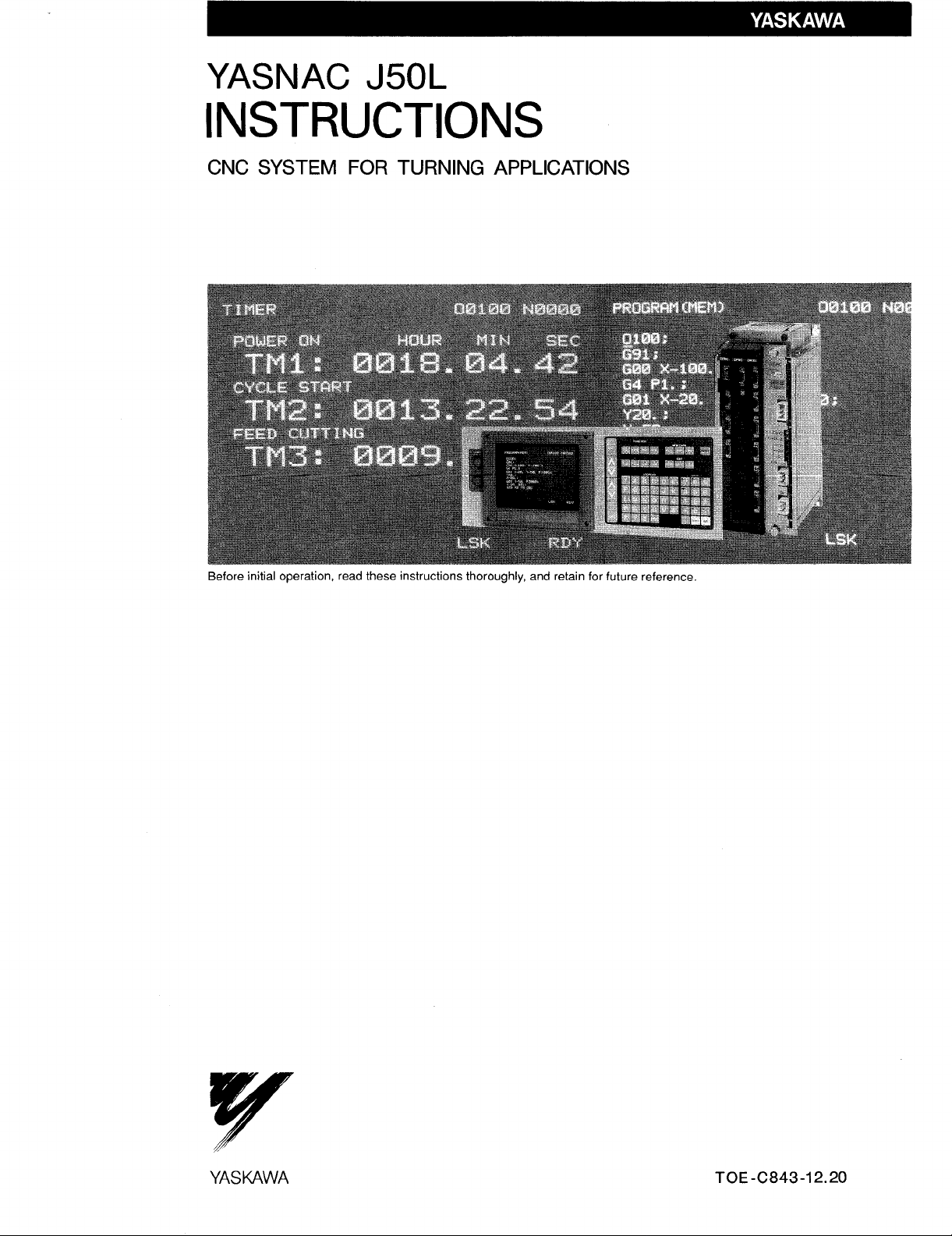
YASNAC J50L
INSTRUCTIONS
CNC SYSTEM FOR TURNING APPLICATIONS
YASUAVVA
TOE-C843-12.20
Page 2
This manual is primarily intended with 9“ CRT character
display (basic)to give operators instructions for YASNAC
J50L programming and operation.
This manual applies to the basic and optionalfeaturesof
YASNAC J50L. The optional features are marked with a
dagger. For the specificationsof your YASNAC J50L, refer
to the machine toolbuilder’smanual.
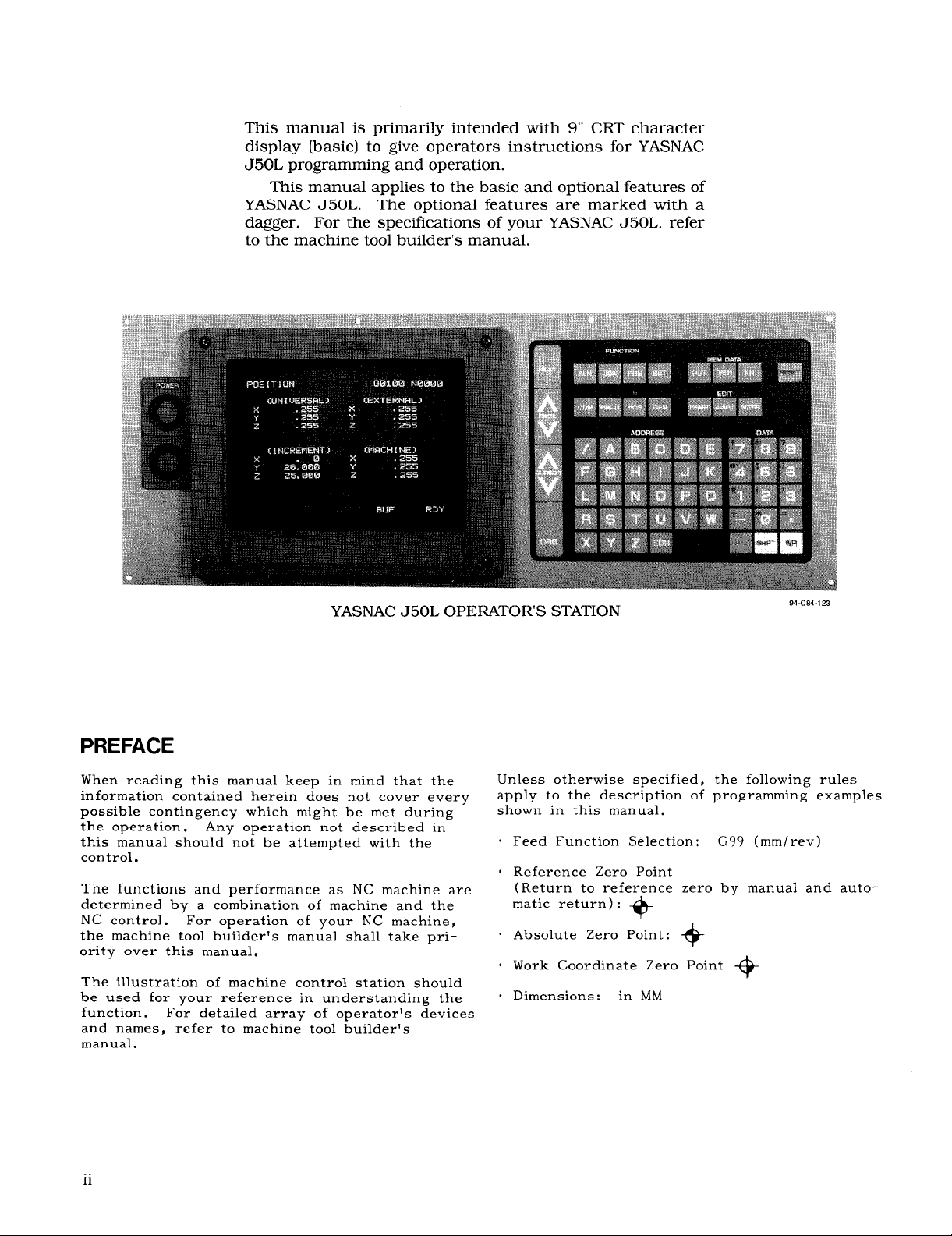
YASNAC J50L OPERATORS STATION
PREFACE
When reading this manual keep in mind that the
information contained herein does not cover every
possible contingency which might be met during
the operation. Any operation not described in
this manual should not be attempted with the
control.
The functions and performance as NC machine are
determined by a combination of machine and the
NC control.
the machine toolbuilder’smanual shalltake pri-
ority over this manual.
The illustrationof machine control station should
be used for your reference in understanding the
function.
and names,
manual.
For operation of your NC machine,
For detailedarray of operatorls devices
refer to machine toolbuilder’s
23
M-CM-1
Unless otherwise specified,
apply to the descriptionof
the followingrules
programming examples
shown in this manual.
Feed Function Selection:
G99 (mm/rev)
Reference Zero Point
(Return to reference zero by manual and auto-
matic return):
Absolute Zero Point:
Work Coordinate Zero Point
Dimensions:
+
+
+
in MM
ii
Page 3
TABLE OF CONTENTS
1. INTRODUCTION 1
2. PROGRAMMING 1
2.1
TAPE FORMAT 1
PROGRAM NUMBER AND SECNJENCE NUMBER 6
2.2
2.3
COORDINATE WORDS
RAPID TRAVERSE RATE 10
2.4
25
SPINDLE-SPEED FUNCTION (S-FUNCTION) 13
TOOL FUNCTION (T-FUNCTION) 14
2.6
MISCELLANEOUS FUNCTIONS (M-FUNCTION) 17
2.7
PREPARATORY FUNCTIONS (G-FUNCTION) 21
2.8
3. NC TAPE PUNCHING 139
3.1 TAPE CODE 139
3.2 PROGRAMMING 139
3.3 NC TAPE 141
7
3.4 NC TAPE HANDLING 141
4. STANDARD NC OPERATOR’S STATION
WITH CRT CHARACTER DISPLAY 142
PUSHBUTTONS, KEYS, AND LAMPS 142
4.1
POWER ON/OFF OPERATION 146
4.2
4.3
DISPLAY AND WRITING OPERATION 146
4.4
LOADING PART PROGRAMS
AND NC DATA INTO MEMORY (IN) 163
4.5
TAPE VERIFYING 166
4.6
EDIT 168
4.7
PART PROGRAM AND NC DATA OUTPUT
OPERATIONS 170
4.8
SUMMARY OF STORING
AND EDITING OPERATIONS 173
5. MACHINE CONTROL STATION 174
5.1 SWITCHING UNITS ON THE CONTROL
STATION
OPERATION PROCEDURE 181
5.2
6. OPERATION PROCEDURE 195
INSPECTION BEFORE TURNING ON POWER 195
6.1
TURNING ON POWER 195
6.2
MANUAL OPERATION 195
6.3
6.4
PREPARATION FOR STORED LEADSCREW
ERROR COMPENSATION AND
STORED STROKE LIMITt 196
PREPARATIONS FOR AUTOMATIC OPERATION 196
6.5
OPERATION IN TAPE AND MEMORY MODE 197
6.6
MANUAL OPERATION INTERRUPTING
6.7
AUTOMATIC OPERATION 197
AUTOMATIC OPERATION IN MDI MODE 198
6.8
6.9
MDI OPERATION INTERRUPTING AUTOMATIC
OPERATION 198
6.10 PREPARATION FOR TURNING OFF POWER
6.11 TURNING OFF POWER 198
APPENDIX 1
APPENDIX 2
APPENDIX 3
APPENDIX 4
APPENDIX 5
APPENDIX 6
174
LIST OF SETTING NUMBERS A-f
LIST OF PARAMETER NUMBERS
STORED LEADSCREW ERROR
COMPENSATION A-24
LIST OF STANDARD lNPUT/OUTPUT
SIGNALS A-25
LIST OF ALARM CODES A-35
LIST OF DATA A-54
198
A-7
...
111
Page 4
INDEX
Subject Chapter
A ABSOLUTE AND INCREMENTAL LNPUTS . . . . . . . . . . . . . . . 2 . . . . 2.3.5. . . . . 8
ABSOLUTE/lNCREMENTAL PROGRAMMING (G9t3,G91) . . . . . . . . 2 . . . . 2.8.31. . . . . 138
AccelerationandDecelerationofRapidTraverseandManlralFeed . . . . . . . 2 . . - - 2.4.3.]. . . . . 12
ADDING PART PROGRAMS . . . . . ., . . . . . . . . . . . . ...4 . . ..4.6.4 . . . ..]69
ADDRESS KEYS O........ . . . . . . . . . . . . . . ...4 . . ..4. ]4. . . ..I43
AddressSearch. . . . . . . . . . . . . . . . . . . . . . . . . . . . 4 . . . . 4.3.3.4.... 151
ALARM CODE(ALM) DISPLAY . . . . . . . . . . . . . . . . . ...4 . ...4.3,9.....161
AlarmCodeDisplay. . . . . . . . . . . . . . . . . . . . . . . . ..4 . . ..4.3 .9.I.... .161
AlarmNumberofMicroprograms. . . . . . . . . . . . . . . . . . . . 2 . . . . 2,8,2~,lo.. . . 83
ArgumentDesignation. . . . . . . . . . . . . . . . . . . . . . . . . 2 . . . . 2.8.23.2... .63
AUTO MODE HANDLE OFFSET.. . . . . . . . . . . . . . . . . . . 5....5.2.7.....194
AUTO MODE HANDLE OFFSETSWITClit . . . . . . . . . . . . - . . 5 . . . . 5,],28.. . . . 181
AUTOMATIC ACCELERATION AND DECELERATION . . . . . . . . . . 2 . . . . 2.4.3. . . . . 12
AUTOMATIC COORDINATE SYSTEM SETTING“t. . . . . . . . . . . . 5 . . . . 52,2 . . . . . 182
AutomaticNoseR Function. . . . . . . . . . . . . . . . . . . . ...2....2.8.19,1 . ...53
AUTOMATIC OPERATION INMDIMODE . . . . . . . . . . . . . . . 6 . . . . 6.8 . . . . . 198
AUTOMATIC RETURN TO REFERENCE POINT (G28). . . . . . . . . . . 2 . . . . 2.8.11. . , . 0 33
AutomaticThreadingCycle(G76) . . . . . . . . . . . . . . . . . . . . 2 . . . . 2,8,25,8. . . . Io3
AutomaticWritingintotheToolcoordinateMemory . . . . . . . . . . . . . 5 . . . . 5,2,3,3.. . . .186
AutomaticWritingintotheWork CoordinateSystemShiftMemory . . 0 . . . . 5 . . . . 5.2.3.4.. . . .186
B
BUFFER REGISTER. . . . . . . . . . . . . . . . . . . . . . . . . . 2 . . . . 2.15.....
BUFFERING FUNCTION (M93,M92)t . . . . . . . . . . . . . . ...2 . . . . 2.7.3. . ...1.
c
CANNED CYCLES (G90,G92,G94) . . . . . . . . . . . . . . . . ...2 . ...2.8.26.....110
CHECKING REGISTEREDPART PROGRAM NUMBER . . . . 0 . . . . . 4 . . . . 4.6.1. . . . . 168
CircularArcMultipleComering(Gl12). . . . . . . . . . . . . . . . . . 2 . . . . 2.8.30,2. . . . 135
CIRCULAR INTERPOLATION(G02,G03) . . . . . . . . . . . . . . . . 2 . . . 0 2.8.4. . . . . 26
CIRCULAR PATH MODE ON/OFFON TOOL RADIUS
COMPENSATION (M97,M96)t . . . . . . . . . . . . . . . . . . ...2.. . . 2,7,4. . ...18
COMMAND DATA DISPLAY . . . . . . . . . . . . . . . . . . ...4 . ...4.3,2.....148
Command DataDisplay. . . . . . . O + . . . . . . . . . . . . . . .4 . . ..4.3 .2148 . ..I48
Command pukeAccumulationRegisterDisplay(COMMAND PULSE) . . . . . 4 . . . . 4.3.4.9. . . . 155
ConditionsfortheAutomaticNoseR CompensationFunctiontobeEnabled . . . 2 . . . . 2.8.19.2. . . , 53
ConsiderationsandRemarksforMacroPrograms. . . . . . . . . . . . . . 2 . . . . 2.8.23.9. . . . 79
CONSTANT DISPLAY . . . . . . . . . . . . . . . . . . . . . ...4 . . ..4.3 .] . . ...146
CONSTANT SURFACE SPEED CONTROL (G96,G97)t c . . . . . . . . . 2 . . . 0 2.8.27.. . . . 116
ControlCommands . . . . . . . . . . . . . . . . . . . . . . . . . . 2 . . . . 2.8.23.6.... 76
CoordinateSystemSetting(G50X_. Z_.) . . . . . . . . . . . . . . . 5 . . . . 5.2.3.5. . . . 188
COORDINATE WORDS . . . . . . . . . . . . . . . . . . . . ...2 . . . . 2.3.....7
COORDINATE WORDS . . . . . . . . . . . . . . . . . . . . ...2 . . . . 2.3.1. . . . .
CORNERING (Gil,G12)t . . . . . . - . - . . . . . . . . . . . ...2 . . . - 2.8,7-....22
CRT CHARACTER DISPLAY . ..C . . . . . . . . . . . . . . ...4 . ...4.1,2.....143
CURRENT POSITIONDISPLAY . . . . . . . . . . . . . . . . . ...4 . ...4.3,4.....152
CURSOR KEYS . . . .. O.. CC . . . . . . . . . . . . . . ...4 . . ..4.1 .8 . . . ..I44
CUTTING DEPTH OVERRIDE SWITCH’iFORG71 ANDG72 . . . . . . . . 5 . . . . 5.1.29.. . . . 181
CYCLE START PUSHBUTTON AND LAMP . . . . . . . . . . . . . . . .5 . . . . 5.1.2. . . . . 175
D
DATA KEYS . . . . . . . . . . . . . . . . . . . . . . . . . . ...4 . ...415.....144
DECIMAL POINTPROGRAMMING. . . . . . . . . . . . . . . ...2 . . . . 2.1.3. . . . .
DELETING PART PROGRAM BLOCKS . . . . . . . . . . . . . . . . 4 . . . . 4.6,5. . . . . 16j
DisplayandDeletingofRegisteredProgramNumber
(PROGRAM NO.TABLEnn)t . . . . . . . . . . . . . . . . . ...4.... 4.3.9.3....162
DisplayandWriteofLocalandCommon Varfab]es. . . . . . . . . . . . . 2 . . . . 2.8.23.8. . . . 79
DISPLAY AND WRITING OPERATION . . . . . . . . . . . . . . ...4 . ...4.3......146
DisplayofSubprogramRunStatus(SUBPROG.NESTING). . . . . . . . . . 4 . . . . 4.3.2.2, . . . 148
DisplayofToolLifeControlUseStatus(TOOLLIFECONTROL) . . . . . . . 4 . . . . 4.3.2.3. . . . 149
DisplayinEDITMode . . . . . . . . . . . . . . . . . . . . . . . . .4 . . ..4.3 .3151 . ..I51
DISPLAYINGAND CHECKING STORED PART PROGRAMS . . . . . . . . 4 . . . . 4.6,2. . . . . 168
DISPLAYINGAND WRITING PARAMETERS . . . . . . . . . . . - . . 4 . . . . 4.3.7. . . . . 159
DisplayingandWritingParameters, , . , , , . . . . . . . . . . . . . 4 . . . . 4.3.7,3. . . . 160
DISPLAYINGAND WRITING SETTINGDATA (SETTING). . . . . . . . . 4 . . . . 4,3,6. . . . . 157
DISPLAYINGAND WRITING TOOL OFFSET DATAt . . . . . . . . . . 4 . . . . 4.3.5. . . . . 155
DISPLAYINGSTATUS INPUT/OUTPUTSIGNALS . . . . . . . . . . . . 4 . . . . 4,3.8. . . . . 160
DisplayinMemoryRttnMode(PROGRAM [MEM]) . . . . . . . . . . . . 4 . . . . 4.3.3.2.. . . .151
Par. Page
iv
Page 5
INDEX (Cent’d)
Subject
D
DISPLAYLOCK/MACHINE LOCK SWITCH . . . . . . . . . . . . . . . 5 . . . . 5.1.19.. . . . 179
DRY RUN SWITCH . . . . . ..O. . . . . . . . . . . . . . . ...5 . ...5.1.18.....179
DWELL (G04)----------- . . . . . . . . . -.......2 . . . . 2.8.5. . ...27
E
EDIT....,.00...o..o . . . . . . . . . . . . . . ...4 . ...4.6......168
EDITKEYS . . . . . . . . . . . . . . . . . . . . . . . . . . . . .4 . . ..4.1 .145. . ..I45
EDITLOCK SWITCH . . . . . . . . . . . . . . . . . . . . . . . . . 5....5.1.22.....180
EIA/ISOAUTO Recognition . . . . . . . . . . . . . . . . . ...3 . ...3.1.2.....139
EMERGENCY STOP PUSHBUTTON. . . . . . . . . . . . . . . ...5 . ...5.1.4.....175
ErrorDetectOffPositioning(G06)
ExampleofHigh-speedM FunctionProcessing. . . . . . . . . . . . . . . 2 . . . . 2.7.8.4. . . . 21
ExercisesofMicroprograms................ , . . . . . 2 . . . . 2.8.23.11. ...84
F
FacingCycleB(G94) . . . . . . . . . . . . . . . . . . . . . . ...2 . ...2.8.26.3....114
FEED FUNCTION (F-AND E-FUNCTION) . . . . . 0 0 0 0 0 , . . 0 0 0 2 , 0 0 . 2.4.2. . . , . 10
FEED HOLD PUSHBUTTON AND LAMP . . . . . . . . . . . . . . . . 5 . . . . 5.].3. . . . .
FEED/MINUTE AND FEED/REVOLUTIONSWITCHOVER . , , . 0 , , . 0 2 . 0 , , 2,8,28 . . . . 117
FeedPerMinute(G98Mode). . . . . . . . . . . . . . . . . . . . . . . 2.. o.2.4,2.2 . . ..1 I
FeedPerRevohrtion(G99Mode). . . ................. . 2 .,, ,2.4.2.1.....10
FEEDRATE OVERRIDE CANCEL SWITCH . . . . . . . . . . . . . . . 5 . . . . 5.1.12.. . . . 178
FinishingCycle(G70) . . . . . . . . . . . . . . . . . . . . . . ...2 . . . . 2.8.25.5....99
FUNCTION KEYS . . .. O.... . .,...,........4.4 . ...4.1.3.....143
G
General. . . . . . . . . . . . . . . . . . . . . . . . . . . . . . . 2 . . . . 2.8.25.1....88
General. . . . . . . . . . . . . . . . . . . . . . . . . . . . . . . 5 . . . . 5.1.8.1.... 176
GENERAL PROGRAM FORM..- . . . . . . . . . . . . . . . . . -3....3.2.2.....139
G50P01NT RETURN SWITCH ~”... . . . . . . . . . . . . . . . . . .5....5,1.24.....180
G50POINTRETURNt . . . . . . . . . . . . . . . 4 . . . . . . ...5 . ...5.2.4.....19]
GroovinginX-Axis(G75) . . . . . . .,, ,,, . . . . . . . . ...2 . ...2.8.25.7....102
HANDLE AXISSELECT SWITCH t.. . . . . . . . . . -.......5 . ...5.1.6.....176
H
HANDLE DIALt (MANUAL PULSEGENERATOR) . . . . . . 0 0 0 . . . 5 0 0 , . 5.1.5. , , . 0 176
HANDLE INTERPOLATIONFUNCTION . . . . . . . . . . . . . . . . . 5 . . . . 5.1.8. . . . . 176
HIGH-SPEEDMFUNCTJON . . . . . . . . . . . . . . . . . . . ...2 . . . . 2.7.8. . ...20
ImprovedG76ScrewCuttingCycleFunction. . . . . . . . . . . . . . . . 2 . . . . 2.8.25.11. . . .109
I
ImprovedMultipleRepetitiveCycleFunction. . . . . . . . . . . . . . . . 2 . . . . 2.8.25.10. . . 108
INCH/METRICDESIGNATION BY G CODE (G20,G21)t . . . . . . 0 . . 2 . . . . 2.8.8. . . . . 31
I/OChannel. . . . . . . . . . . . . . . . . . . . . . . . . . . . . 2 . . . . 2.7.8.1....20
INPUTTINGSETTINGDATA AND PARAMETER DATA . . . . . . . . . . 4 . . . . 4.4.5. . . . . 166
INPUTTINGTOOL OF OFFSETDATA INTO MEMORY . . . . . . . . . 0 4 . . . . 4.4.4. . . . . 166
InputUnitand10TimesInputUnit, . . . c c c o . . . 0 . . . . . . . . 2 . . . 0 2.3,3.1.. . . . 7
INSPECTIONBEFORE TURNINGON POWER . . . . . . . . . . . . . . 6 . . . . 6.1. . . . . . 195
INTERLOCK INPUT (INTERLOCK). . . . . . 0 . . . . . . . . . . c . 5 . 0 . . 5.1.23.. . . . 180
InternalToggleSwitchest..... . . . . . . . . . . . . . . . . . . . 4 . . . . 4.3.6.2.... 158
INTRODUC~ON . . . . . . . . . . . . . . . . . . . . . . . . ...1 . . . . . . . . . ...1
JOG FEEDRATE SWITCH AND FEEDRATE OVERRIDE SWITCH . . . . . . 5 . . . . 5.1.10.. . . . 177
J
JOG PUSHBUTTONS AND RAPID PUSHBUTTON . . . . . . . . . . 0 . 5 . . . . 5.1.9. . , . . 177
KEEPINGOF NC TAPE . . . . . . . . . . . . . . . . . . . . . . . . 3....3.4.2.....141
K
L
LABEL SKIPFUNCTION . . . . . . . . . . . . . . . . . . . . . . . .2 . . . . 2.1.4. . ...6
LEAST INPUTINCREMENT AND LEAST OUTPUT INCREMENT . . . . . . 2 . . . . 2.3.3. . , . . 7
LeastOutputIncrement. . . . . . . . . . . . . . . . . . . . . . . . . 2 . . . . 2.3.3.2.... 8
LINEARINTERPOLATION(GOl)t. . . . . . . . . . . . . . . . ...2 . . . . 2.8.3. . ...25
LISTOF ADDRESS CHARACTERS AND FUNCTION CHARACTERS . . . . . 2 . . . . 2.1.2. . . . . 4
LISTOF ALARM CODES O..,., .,..,.,,4.000..APPENDIX5 ...,.... A-35
LISTOF DATA . . . . . . . . . . . . . . . . . . . . . . . .. APPENDIx6 . . . . . . .. A-54
LISTOF GCODESOO. ., CO.. . . . . . . . . . . . . . . ...2 ,0,,2.8.1.,,0,21
LISTOF PARAMETER NUMBERS . . . . . . . . . . . . . . . . APPENDIX2 . . . . . . . .
LISTOF SETTINGNUMBERS,,, ,.OO,O. ., . . . . .. APPENDIX 1 . . . . . . . . A-1
LISTOF STANDARD INPUT/OUTPUTSIGNALS . . . . . . . . . . APPENDIX 4 . . , . . . . . A-25
LISTOF TAPE CODE .C .,.., ,,,.,.so,o.,,,$.13 ... ,3.1.1 ooo, .139
LOADING PART PROGRAM TAPE INTOMEMORY - - . . . . - . - . . . 4 . - . . 4.4,1. - . . . 163
LOADING PART PROGRAMS AND NC DATA INTO MEMORY (IN). 0 0 0 . 4 . . . . 4.4 0 . . 0 “ 163
LOADING PART PROGRAMS BYMDI . . . . . . . . . . . . . . . . . .4 . ...4.4.3 . . ...165
M
MACHINE CONTROL STATION . . . ., . . . . . . . . . . . . ...5 . . . . . . . . . ...174
MacroPromamCallCommands. . . . . . . . . . . . . . . . . . ...2....2.8.23.1 . ...62
. . . . . . . . . . . . . . . . .
Chapter
2
Par. Page
. . 2.8.2.2.. . . . 25
175
A-7
Page 6
INDEX (Cent’d)
Subject
M MACRO PROGRAMS (G65ANDG67) . . . . . . . . . . . . . . . . . . 2 . ..” 2.8.23.”””” 61
MaintenanceHistoryDisplay(MAINTENANCE) . . . . . . “ “ “ o “ “ $ - 4 ‘ - - “ 4.3.9.50 “ “ “ 163
MAKING ADDITIONTO A PART PROGRAM . . . . . . . . + . . “ “ - 4 “ “ - “ 4.4.2“ . 4 ‘ “ 165
MANUAL ABSOLUTE SWITCH... . . . . . ..”. ”””” +---5 ““”” 5.1.21.””” ”180
MANUAL INTERRUPTIONPOINTRETURN SWITCH . . . . . . . . . ‘ “ 5 “ “ “ “ 5.1.25.“ “ “ “ 181
MANUAL INTERRUPTIONPOINTRETURN7 . “ + $ . . “ “ - . “ . “ “ 5 “ “ “ “ 5.2.5- - “ “ - 191
MANUAL OPERATION . . . . . . . . . . . . . . . . . ..”<””6 ““”” 6.3” ”””” ”195
MANUAL OPERATION INTERRUPTINGAUTOMATIC OPERATION . . - “ 6 “ “ “ “ 6.7- “ “ - “ “ 197
MANUAL PULSE MULTIPLY SELECT SWITCH”t . . . . . . . . . - “ “ 5 0 0 “ o 5.1.7‘ o “ “ o 176
MANUAL REFERENCE POINT RETURN SWITCH”I’. . . . . . . . . . . . 5 “ “ “ “ 5.1.14“ “ - “ “ 178
MANUAL RETURN TO REFERENCE POINT o . . . . . “ . “ $ “ “ o “ 5 “ “ “ “ 5.2.1“ “ “ “ “ 181
MAXIMUM PROGRAMMABLE DIMENSIONS . . . . . . . . . . . . . . 2 . . . . 2.3.4. . . - “ 8
MAXIMUM SPINDLE-SPEEDSETTING(G50)“t “ o . . . “ “ “ “ “ “ o “ 2 “ “ “ - 2.8.21“ “ “ “ 58
M CODES FOR INTERNAL PROCESSING(M90T0 M109) . . . . . . + . “ 2 “ - “ “ 2.7.2“ “ “ - - 17
MCODESFOR STOP(MOO,MO1,M02,M30) . . . . . 0 “ o c c “ “ c . 0 2 “ + “ o 2.7.10 0 0 “ . 17
MDI OPERATION INTERRUPTINGAUTOMATIC OPERATION . . . “ - 0 6 0 0 “ . 6.9 - “ “ “ “ 198
MEASURED WORKPIECE VALUE DIRECTINPUTt - “ “ “ - “ . “ “ - “ “ 5 e “ “ “ 5.2.3“ - - - “ 182
MEMDATA (MEMORY DATA)KEYS. . . . . . . . . . . . ..+ 4..4 ‘+0” 4.1.11$+”” ”145
MessageDisplay(ALARM)t”.... “..”.””.+.”+.”””*4 ““. .4.3.9.2. ”. <161
M-FUNCTION LOCK SWITCH (AUXILIARYFUNCTION LOCK) . . . . . . 5 . . . . 5.1.20.. “ “ . 180
MISCELLANEOUS FUNCTIONS (M-FUNCTION). “ “ “ “ “ . . - “ “ “ “ 2 “ “ “ “ 2.7“ “ “ “ “ “ 17
MODE SELECT SWITCH . . . . . . . . . . . . . . . . . ..-”-”5 ‘“”” 5.1.1””” ”-174
MODIFYING PART PROGRAM BLOCKS “ . “ “ “ “ “ - “ - “ “ - - “ “ 4 “ “ “ “ 4.6.3“ “ “ “ “ 168
M3-DIGITBCDOUTPUTt. ..O. . . . ..”” .”. ”.. ”.””2 .“. ”2.7.7 ”--”-20
Mult-blockWritingandOperationinMDI Mode . . . - . - “ - . “ “ “ “ “ 4 “ “ “ “ 4.3.3.1“ “ “ “ 150
MULTIPLE CORNERING (Gill,Gl12)”t. “ “ “ . - - “ o 0 0 . . - “ “ “ 2 “ “ “ “ 2.8.30.“ “ “ “ 127
MULTIPLE REPETITIVECYCLES (G70TO G76)“t o 0 0 “ “ “ “ - “ “ “ “ 2 “ “ “ “ 2.8.25“ “ “ “ “ 88
MULTI-START THREAD CUTTING (G32)+ ‘ . “ o 0 0 “ . “ “ “ . . “ “
N NC TAPE . . . . . . . . . . . . . . . . . ..”” ””” ”-”---3 ““”” 3.3- ””-” ”141
NC TAPE CHECK . . . . . . . . . ““. ”””” .””. ”’””””3 ‘“”” 3.3.3””” ”-141
NC TAPE HANDLING . . . . . . . . . . ..++ ””-” ”<. .’”3 ““”” 3.4” ”””” ”141
NC TAPE PUNCH””””””””” “.. .””” ”””” ””””””3 ..”” 3.3.2””+” ”141
NC TAPE PUNCHING . . . . . . . . “.. ”.”” -””. +”. ”””3 ““””””””””””139
NEXT KEY . . . . . . . . . . . -“.”””””””””””””” “4”” .”4.1.6””” ..144
New ToolSetterFunction. . . . . ....””...”””.””” 0“”5”. +” 5.2.3.9--o ’189
No.ofServoLagPulsesDisplay(ERROR PULSE) . “ “ “ “ . “ “ “ “ “ . “ 4 “ “ “ “ 4.3.4.8“ “ - “ 155
Notes..........++. “o..””.”.”.”.... .“.2. .” . 2.7.8.3..”- ’21
0 OffsetCalculationofAutomaticNoseR CompensationApproachandRelief. “ “ “ 2 . “ “ “ 2.8.19.3“ “ “ - 54
OffsetScreenDisplay..”.”. ..”.”.””...”.”.. ..”5”+” .5.2.3.8-+.. 1~~
Operation”””--””””””” ““”-”””.””””””””” “5”” ””5.1.8.2”””” 176
OperationCommands ”””... ““.”..”.”..”++-” ““”2+”” ” 2.8.23.5-++. 75
OPERATION INTAPE AND MEMORY MODE . “ “ “ “ “ “ “ “ “ “ “ “ . 6 - - - “ 6.6“ “ “ “ “ “ 197
OPERATION PROCEDURE””””” “.. ”””” -””-- .-”””5 “.-” 5.2” .”” ”-181
OPERATION PROCEDURE . . . . . . . . . ..”” ””. ””””””6 ““-””””’””””195
OpemtionTimeDisplay”--”.. “..””-”””.-.””..” “4-.””4.3.9.4.”.””16~
oPTIoNALBLocK sKIP(/1-/9)*...” ““””””””””””””””2” ““”2.’2.3 ”””””
OPTIONAL BLOCK SKIPSWITCH.’ ‘“”” ”””. ””-” -<”””5 ““”” 5.1.17--”” ”179
ORG(ORIGIN)KEYS..””.””” ““. ”””” ”””- ””””””4 ‘“”” 4.1.9”””” ”145
OTHER MCODES ””-””.””” ..”+ ””-” --”” ”.. ””2 ““””2.7.6-”-”-19
OUTPUTTING PART PROGRAM TO PAPER TAPE “ “ . . . . . . . . . “ 4 “ “ “ “ 4.7.1“ “ - “ “ 170
OUTPUTTING SETTING/PARAMETER DATA TO PAPER TAPE “ - “ . “ “ 4 “ “ “ - 4.7.3“ “ “ “ “ 171
OUTPUTTING TOOL OFFSET TO PAPER TAPE ~ “ . . . . “ “ “ . “ “ . 4 - “ - + 4.7.2“ “ “ - 0 171
OverviewofMacroProgrtamBody “ - ‘ - . . “ “ “ “ “ “ . . - “ “ “ “ “ 2 “ . “ “ 2.8.23.3“ “ “ - 65
PAGEKEYS,,,O..,.... . ..”””.----.-”””” ‘4”” ””4.1.7””””” 144
P
PAPER TAPE . . . . . . . . . . . . . . . . . . . . . . . . . . . “3-- ””3.3.1””””” 141
ParametersofBitDisplayFormat,. . - “ . “ “ “ - “ “ . “ “ “ “ < “ “ “ 4 “ “ “ “ 4.3.7.1“ “ “ “ 160
ParametersofDecimalDisplayFormat- . . . . . . . . . . . . . . . . . . 4 . . . . 4.3.7.2. 0 “ - 160
parameters. . . . . . . . . . . ““”””””..”..”””. ““”2. ””” 2.7.8.2””. “20
parameters. . . . . . . . . . . ......””””.”.””” .“”5. ””” 5.2.3.2”.” “185
PART PROGRAM AND NC DATA OUTPUT OPERATIONS - “ “ . “ “ “ “ 4 “ “ “ “ 4.7“ “ “ “ “ “ 170
PatternRepeating(G73) . . . . . . . . . . . . . . . . . . . . . ...2 .“””2.8.25.4. .””98
PeckDrillinginZ-axis(G74) ..”.” ““””””.”””.””””””2 ‘“”- 2.8.25.6”-”-101
Position. . . . . . . . . . . . . . . . . . . . . . . . . . . . ..4” ””” 4.3.4.4”‘“”153
Chapter
2 “ . “ . 2.8.16.0 “ - “ 38
Par.
Page
Page 7
INDEX (Cent’d)
Subject Chapter
Position[ABSOLUTE] . . . . . . . . . . 4 . . . . . . . . . . . ...4 ..”” 4.3.4.2. ””” 152
P
Position[EXTERNAL] . . . . . . . . . . . . . . . . . . . . . ...4 “.”. 4.3.4.1..”” 152
Position(EXTERNAL)“O’’Setting. . . . . . . . . . . . . . . . . . . “ 5 “ “ “ ‘ 5.2.3.6- - “ “ 188
Position[INCREMENT] . . . . . . . . . . . . . . . . . . . . . . . .4 . . ..4.3 .4.3. . ..1S3
POSITIONING(GOO,G06) . . . . . . . . . . . . . . . . . . . . ..”2 .“””2.8.2”””””22
Positioning(GOD). . . ...!... . . . . . . . . . . . . . . ..”2 ““”.2.8.2.1....22
POSITIONSTORED PUSHBUTTON~ . . . . . . . . . . . . . - . . . “ 5 “ “ “ “ 5.1.30 “ - “ “ 181
POWER ON/OFF OPERATION . . . . . . . . . . . . . . . . . . . . .4. ””.4.2””””” .146
POWER ON/OFFPUSHBUTTONS. . . . . . . . . . . . . . . . . . .4. ..”4.1.1”. ””” 142
PrecautionsinProgrammingG70throughG76 . . “ . “ “ . “ . . 0 . “ . “ 2 + - “ . 2.8.25.90 0 “ “ 105
PREPARATION FOR STORED LEADSCREW ERROR COMPENSATION
AND STORED STROKE LIMIT”t. . . . . . . . . . ...”””””” .6”” ””6.4””$-”” 196
PREPARATION FOR TURNING OFF POWER . . . . . . . . . . . . . . 6 . . . 0 6.10 0 “ “ “ + 198
PREPARATIONS FOR AUTOMATIC OPERATION “ “ “ “ “ “ . “ “ “ . “ 6 . + . “ 6.5“ - “ - “ “ 196
PREPARATORY FUNCTIONS (G-FUNCTION). . . . . . . . . 0 . . . . 2 . . . - 2.84 “ . “ “ < 21
PROCESS SHEET . . . . . . . . . . . . . . . . . . . ..”” ”””.3 ““”” 3.2.1”””” ”139
PROGRAMMING . . . . . . . . . . . . . . . . . . . . . . . . ...2 “c.”.”””””.*1
PROGRAMMING . ..”.....” . . . . ..+-- ”-”” .”””3 .“. ”3.2”””””” 139
PROGRAMMING OF ABSOLUTE ZERO POINT(G50). . . . . . . . . . 0 2 . . . 0 2.8.20+ “ o “ . 57
PROGRAM MIRROR IMAGE (G68,G69)t . . . . . . . . . . . . . . . . 2 - . “ - 2.8.24 - “ “ “ 87
PROGRAM NUMBER . . .. O.. . . . . . . . ..”- ””. .-”2 ““”” 2.2.1.”. .”6
PROGRAM NUMBER AND SEQUENCE NUMBER . . . . . . . . “ “ “ “ 2 “ “ - “ 2.2 “ “ ‘ “ “ 6
PROGRAM RESTART SWITCH t.. . . . . . . . . . . . . ...++ “5. ..”5.1.26. +”” 181
PROGRAM RESTART t...., . . . . . . . . . . . . . . . . ..”5””””5.2.6”””4 192
ProgramRetur n........ . . . . . . ..-+ +.. O.O “--4 ”””” 4.3.4.5”””- 154
PUSHBUTTONS, KEYS,AND LAMPS . . . . . . ..++ ”.”- ”.”4 ““”” 4.1” ””. .” 142
R RADIUS PROGRAMMING FOR CIRCULAR
INTERPOLATION(G22,G23)~. . . . . . . . . . . . . . ...”.” .2. ”””2.8.9””. .”31
RAPIDTRAVERSE RATE -+”..+ ‘“”--”--””””-””””2 ““”” 2.4” -”. ”10
RAPIDTRAVERSE RATE..... . . . . . . . ...+-”””-” “2”. ..2.4.1 ”””””10
RAPIDTRAVERSE RATE OVERRIDE SWITCH “ “ “ “ “ “ “ “ “ “ “ - “ 5 “ “ “ “ 5.1.11“ “ “ “ 178
REFERENCE POINT CHECK (G27). . . . . . . . . . . . . . . . . . . 2 . . . . 2.8.10“ “ “ “ 32
REFERENCE POINT LAMPS.... . . ..”” -””” ””----”5 ‘“”- 5.1.15--”” 179
RegistrationofMicroprograms. . . . . . . . 0 # . . , , . . . . . . . 2 0 “ ‘ “ 2.8.23.7“ . “ + 78
RESET KEY . . . . . . . . . . . . . . ...--”.””””””” “4”” ”-4.1 .12. ””” 145
RETURN FROM REFERENCE POINT(G29) , , . . . . 0 0 0 “ “ “ o “ o 2 . . “ . 2.8.12 - 0 0 0 34
2ND REFERENCE POINTRETURN (G30)t . . . . . . . . . , . . . . . 2 . . . . 2.8.13 “ “ “ “ 34
s
SEQUENCE NUMBER ”O” OO. .O 0“o+”o$o.000--”-”2 ‘+$ ’2.2.2 <”-””6
SettiogDataofBitDisplayFormat“ . “ “ “ “ . “ “ “ “ . “ . “ “ “ “ “ “ 4 “ o “ - 4.3.6.1- “ “ “ 157
SettingDataofDecimalDisplayFormato “ “ “ . 0 “ “ . “ “ “ “ o “ o “ c 4 $ 0 $ 0 4.3.6.3- - 0 0 158
S4-DIGITPROGRAMMING At.... . . . . . . . . ..”. ”””””2 .“””2.5.2”. ”.13
S4-DIGITPROGRAMMING B”t ”.. “.. ..”” ”.-. .”-O ”-2 ..-” 2.5.3.. +0.14
SIMULTANEOUS CONTROLLABLE AXES . . . . . “ “ “ “ “ . “ . “ “ 2 “ “ “ “ 2.3.2“ - “ “ “ 7
SINGLE BLOCK SWITCH O....” “4.””””..00”.”””05 ““”. 5.1.16 ””+ +179
SKIPFUNCTION (G31)”t. . . . . . . . . . . . . . . . . . ..”””2 ““. .2.8.14 ””””35
SUBROUTINE PROGRAM (M98,M99) . . . “ “ “ . c “ “ “ . “ . . 0 . 2 . . “ “ 2.7.5“ “ “ “ “ 18
SpindleCounter. . . . . . . . . . . . . . . . ..”....”” ““”4. ””” 4.3.4.7””” ’155
SPINDLESPEED OVERRIDE SWITCHt + “ “ + “ - - “ “ “ - “ “ “ “ “ 5 “ “ “ “ 5.1.13“ “ “ “ 178
SPINDLE-SPEEDFUNCTION (S-FUNCTION) . . . . . . “ . . “ “ “ “ “ 2 - - - - 2.5“ “ o 0 “ “ 13
SPLICINGNC TAPES . . . . . . . . . . . . . . . . . . ...”. “3”” ””3.4.1”””-” 141
S2-DIGITPROGRAMMING (SPECIALSPECIFICATIONS). . “ “ “ “ . “ “ 2 “ . “ “ 2.5.1“ “ “ - “ 13
STANDARD NC OPERATORS STATION
WITH CRT CHARACTER DISPLAY.. .....””””..”.”””+4 .“””. .”. ..”” 142
StockRemovalinFacing(G72) “ “ “ “ “ “ . “ “ . “ “ . “ . “ “ “ “ “ “ 2 “ + “ “ 2.8.25.3“ “ “ “ 95
StockRemovalinTuming(G71). . . . .........”..””.”.2 “.. .2.8.25.2. ”.”89
STORED LEADSCREW ERROR COMPENSATION . - . “ “ “ - “ “ . APPENDIX3 “ “ “ - “ - “ “
STORED STROKE LIMIT(G36-G39). . . . 0 . . “ . . “ . . “ . “ . “ 2 “ - 0 0 2.8.18“ “ “ “ 41
StoredStrokeLimit. . . . . . . ...........”+”.+ “.”4. ”-” 4.3.4.6+”- “154
SUMMARY OF STORING AND EDITINGOPERATIONS . . . . . . . . “ “ 4 - “ “ “ 4.8“ “ “ “ “ “ 173
SWITCHING UNITSON THE CONTROL STATION . . . . . . . - . . . . 5 . “ “ “ 5.1“ “ “ “ “ “ 174
T TAPE CODE . . . . . . . . . . . . . . . . . . . . . . . . . ..+”3 ““”” 3.1” ”””” ”139
Par.
Page
A-24
vii
Page 8
INDEX (Cent’d)
Subject Chapter
T TAPE FORMAT . . . . . . . . . . . . . . . . . . . . . . . . ...2 . . . . 2.1. . . ...1
TAPE FORMAT . . . . . . . . . . . . . . . . . . . . . . . . ...2 . . . . 2.1.1. . ...1
TAPEVERIFYING . . . . . . . . . . . . . . . . . . . . . . . . . . 4 . . . . 4.5. . . . . .166
TaperMultipleCornering(Glll). . . . . . . . . . . . . . . . . . . . 2 . . . . 2.8.30.1. . . 127
T4-DIGITPROGRAMMING . . . . . . . . . . . . - . . . . . . ...2 . . . . 2.6.1. . ...14
TheG40GO1X_ Z_ I_ K_ ;CommarrdCancelFunctionisAlsoAvailable
intheAutomaticNoseRFunction. . . . . . . . . . . . . . . . . . . . 2 . . . . 2.8.19.4. . . . 57
THREAD CUTTING,CONTINUOUS THREAD CUllTNG (G32). . 0 . . . 0 2 0 . 0 0 2.8.15. . . . 36
ThreadingCycle(G92). . . . . . . . . . . . . . . . . . . . . . . . . 2....2.8,26.2....111
TOOL FUNCTION (T-FUNCTION).. . . . . . . . . . . . . . . ...2 . . . . 2.6 . . ...14
TOOL LIFECONTROL (G122,G123)~. . . . . . . . . . . . . . . . . . 2 . . . . 2.8.29 . . . . 118
ToolSetterFunction . . . . . . . . . . . . . . . . . . . . . . . . . 5 . . . . 5.2.3.1... .185
TOOL NOSE RADIUS COMPENSATION (G40THROUGH G44). . . . . . . 2 . 0 . . 2.8.19. . . . 42
TOOL OFFSETMEMORY ”~. . . . . . . . . . . . . . . . . . . . . . 2 . . . . 2.6.2. . ...14
TOOL OFFSET VALUE (GIO)T. . ..O . . . . . . . . . . . . . ...2. , . . 2.8.6. . ...28
TOOL POSITIONOFFSETS . . . . . . . . . . . . . . . . . . . ...2 . . ..2.6 .3”” ”””14
TurningCycleA(G90) ..,.... . . . . . . . . . . . . . . ...2 . . ..2.8 .26.1.”” .110
TURNLNG OFF POWER . . . . . . . . . . . . . . . . . . . . . ...4 . ...4.2.2.....146
TURNING ON POWER . . . . . . . . . . . . . . . . . . . . . ...4 .“””4.2.1”” ...146
TURNLNG OFF POWER . . . . . . . . . . . . . . . . . . . . ...6 ..”” 6.11 .””” ”198
TURNING ON POWER .O. ..O. ...c””.”t”””””””.6 .“. .6.2 ”””” ”” 195
v VARIABLE LEAD THREAD CUTTING”t. . . . . . . . . . . . . . . . . 2 . . . . 2.8.17.. “ . “ 40
Variables. . . . . . . . . . . . . . . . . . . . . . . . . . . ““.2 ””” . 2.8.23.4..” “65
VERIFYINGPART PROGRAM TAPE. . . . . . . . . . . . . . . ...4 . . ..4.5 .1. .” ..167
VERIFYINGSETTINGAND PARAMETER TAPES - “ “ “ . “ “ “ “ “ - 0 4 “ o “ “ 4.5.3- “ “ “ - 167
VERIFYINGTOOL OFFSETVALUE TAPE . . . . . . . . . . . . . . “ “ 4 “ “ - “ 4.5.2“ “ “ “ “ 167
W WORK COORDINATE MULTI-SHIFT(G50T,G51)“~. . . . . “ o “ . “ o . 2 “ “ “ “ 2.8.220“ “ “ “ 59
WORK COORDINATE SYSTEM SHl~t . . . . . . . . . . . . . . . . . 2 “ $ + $ 2.6.4- - “ “ “ 16
WorkCoordinateSystemSettingB . . . “ - - “ “ “ “ . . “ “ “ . . . . . 5 - - - - 5.2.3.7“ “ . “ 188
WRITING INBLOCKS AND DISPLAYINGCONTENTS BY MDI . . . . . + 4 0 “ “ o 4.3.3“ . “ “ o 150
WritingintotheToolCoordinateMemory “ “ “ “ “ “ “ “ “ “ “ “ “ “ “ “ “ 5 “ . “ “ 5.2.3.10“ “ - “ 189
WritingProcedure. . . . . . . ....”.......””.” .“”5” ...5.2.3.11””.+ 189
WritingtheZ-axisWorkCoordinateSystemShiftAmount . . “ “ “ “ “ “ “ “ 5 “ “ “ “ 5.2.3.12+ “ “ “ 190
x X-AXISDIAMETER/RADIUSSWITCHING . . . c . c . + + # . 0 . - 0 - 2 0 0 0 “ 2.3.6“ “ “ o 0 9
X-AXISMIRROR IMAGE SWITCH~ . . . . . . . . . . . . . . . . . .5 . . ..5.1 .27.”””” 181
Par. Page
Page 9
1. INTRODUCTION
YASNAC J50L,“UltraspeeddualprocessorCNC” isa combinationoftwo high-performance16-bitmicroprocessors
runningin parallel.Incorporatingour modern system
technique,itisdesignedtoprovidethehighestlatheperformance.
The dual processor CNC system drasticallyreduces the data processing time to meet highspeed cutting.
creased by the use of high–speed buffer func–
tionand buffering function.
Enhanced cutting capabilityincludes a maximum
of 24 meters/reinfeed command, precise feed E
command, 500-milimet-erlead thread cutting,
continuous thread cutting, multiplethread
cutting, and variable pitch thread cutting.
To meet FMS trends, program interruptfunction,toollifecontrol,user macro, toolset
error correction, stored stroke limitper tool,
and other functionscan be installed.
Block-to-blockstop time de-
2. PROGRAMMING
Part program memory can be extended to a
maximum of 320 meters. Its data input/output
interfaceis availablewith FACIT, RS232C and,
in addition,RS422 serialinterfacecapable of
high-speed long distancetransmission.
Programming is further facilitatedby improved
toolradius compensation function,G 50–work
coordinatesystem setting,angle-specifiedlinear interpolation,and combined beveling/round–
ing function.
The servo functionuses a drasticallyminiaturized and low–noise, newly transistorizedPWM
controlunit and a high–performance DC servo
motor.
The positionfeedback is availablewith the
standard pulse generator (PG ) system and,
the inductosyn-appliedcomplete closed lcQp
system.
2.1 TAPE FORMAT
2.1.1TAPE FORMAT
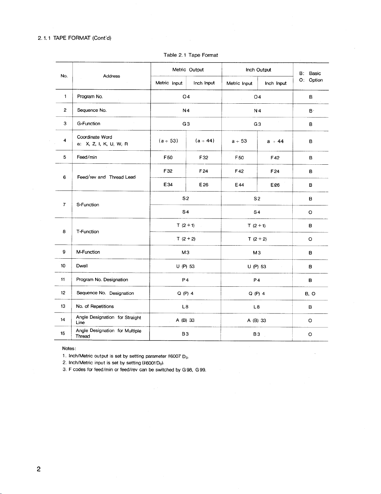
A variableblock format conforming to JIS# B
6313 is used for YASNAC J50L.
Table 2,1 shows the tape format.
followingthe address charactersin Table 2.1
indicate-the programmable number of digits.
EXAMPLE
+
4
a
[[L
# Japanese IndustrialStandard
3
L
Down to th,rd
decimal places
Four dlgils of
Integer
1
I
Numerals
!n mm or Inches
Note: The decimal point may be omitted in
actualprogramming.
including decimal points, refer to 2.1.3
Decimal Point Programming.
The leading zeros can be suppressed for alladdress codes.
med, but allminus signs must be programmed.
In the manual, EOB code in a program example
is represented by a semicolon (;). In actual
programming, CR (EIA code) or LF /NL (1S0
code ) should be used instead of the semicolon
(;).
Plus signs need not be program-
For making a program
Page 10
2.1.1TAPE FORMAT (Cent’d)
2.1Tape Format
Table
No.
1
Program No,
Sequence No.
2
G-Function
3
Coordinate Word
4
a: X, Z, 1,K, U, W; R
5
Feed/rein
Feed/rev and Thread Lead
6
7
S-Function
8 T-Function
Address
Metric Output
Metric Input Inch Input
04 04 B
N4 N4
G3 G3 B
(a+ 53)
F 50 F32
F32 F 24
E34 E26 E44
(a+44)
S2 S2 B
S4
T (2+1)
T(2+2) T(2+2)
Inch Output
Metric Input
a+53
F 50
F42
T(2+I)
B: Basic
Inch Input
O: Option
a+44
F 42 B
F24 B
E!26 B
S4 o
B
B
—
B
o
9
M-Function
10
DwelI
ProgramNo. Designation
11
12
Sequence No. Designation
13
No. of Repetitions
Angle Designation for Straight
14
Line
Angle Designation for Multiple
15
Thread
Notes:
1. Inch/Metric output is set by setting parameter #6007 DS
2. Inch/Metric input is set by setting (#6001 Do).
3. F codes for feed/rein or feed/rev can be switched by G 98, G 99,
M3
u (P)53
P4 P4
Q (P) 4
L8 La B
A (B) 33 A (B) 33
B3 B3
M3 B
u (P)53 B
B
Q (P) 4 B, O
0
o
2
Page 11
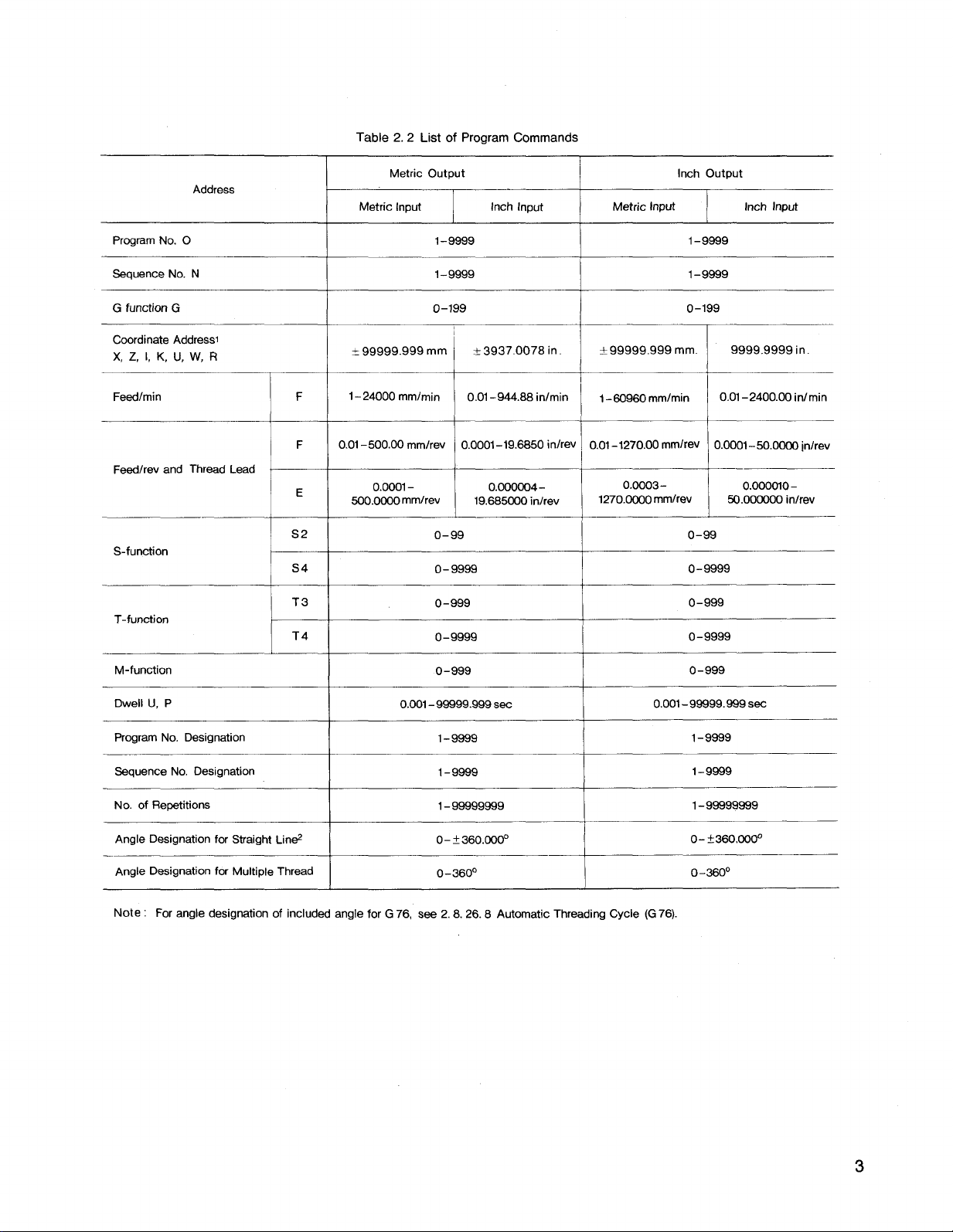
Table 2.2 List of ProgramCommands
Address
Program No. O
Sequence No. N
G function G
Coordinate Address
X, Z, 1, K, U, W, R
Feed/rein
Feed/rev and Thread Lead
S-function
T-function
S2
S4
T3
T4
F
F
E
1–24000 mmlmin
0.01–500.00 rnmlrev
Metric Output
Metric Input
+99999.999rnrn I *3937.0078 in. j *99999.999 mm. I 9999.9999 in.
I Inch Input
1–9999
1-9999
0-199 0-199
0.01–944.88 in/rein
1
I I I
0.0001 –19.6850 inlrev I 0.01–1270.00 mmlrev 0.0001-50.0000 ~n/rev
I
I Metric Input I inch Input
1–80960 mmlmin
I
Inch Output
1–9999
1–9889
0.01–2400.00 inlmin
I
—
0.0001- 0.ooooo4-
500.OCOOmmlrev 19.685030 in/rev
o-99 0-99
0-9999
0-999
0-9999
0.ooo3-
1270.0000 mmlrev
1
0-9999
0-999
0-9999
0.000cno-
50.000000 inlrev
M-function
Dwell U, P
Program No. Designation
Sequence No. Designation
No. of Repetitions
Angle Designation for Straight Lin&
Angle Designation for Multiple Thread
Note : For angle designation of included angle for G 76, S= 2.8.26.8 Automatic Threading Cycle (G76).
0-999
0.001–99999.999 Sec
1-9899
1-9689
1–99999999
0-?360.000°
0–360°
0.001-99999.999 Sec
0-999
1-9899
1–9999
1-99999989
0– ~36&r3@3°
o–3800
3
Page 12
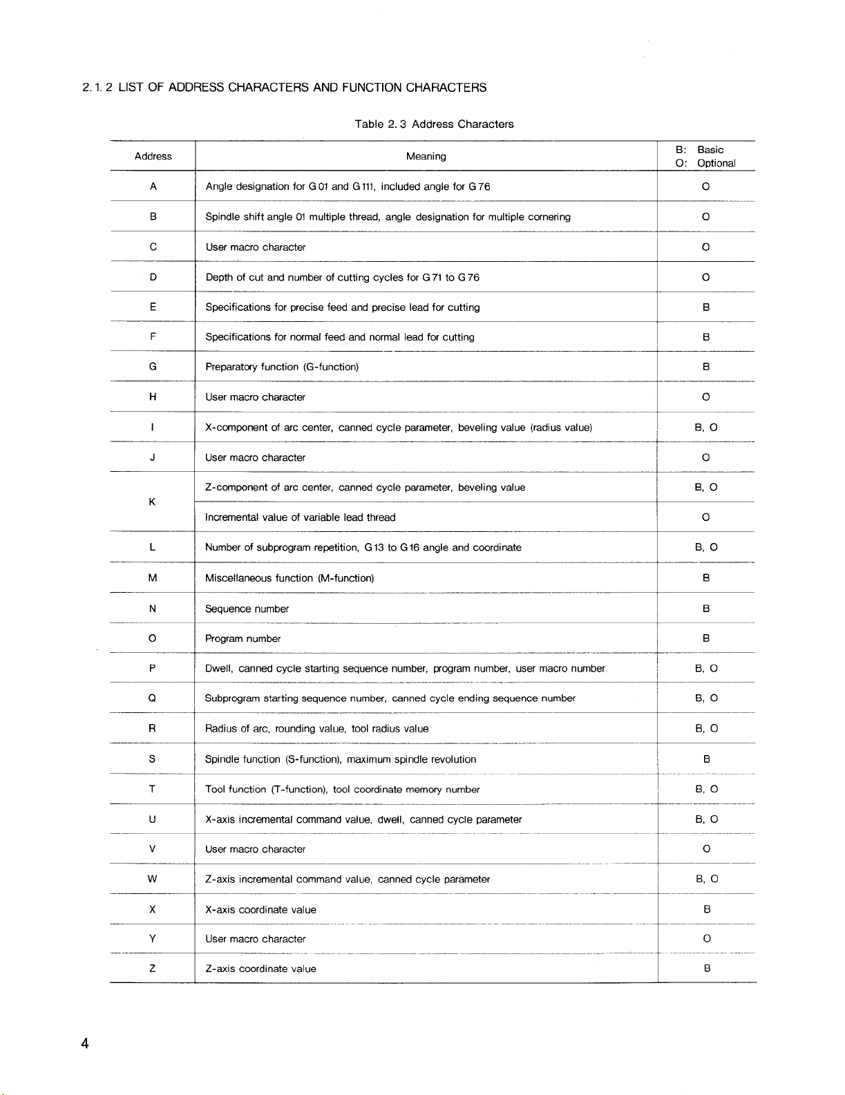
2.1.2 LIST OF ADDRESS CHARACTERS AND FUNCTION CHARACTERS
Table 2.3 Address Characters
Address
A
Angle designation for GOland Gill, included angle for G76
Spindle shift angle Ol multiple thread, angle designationfor multiple corneringB
Meaning
c User macro character
D Depth of cut and number of cutting cycles for G 71 to G 76
E Specifications for precise feed and precise lead for cutting
F Specifications for normal feed and normal lead for cutting
G
H
I
J
K
L
Preparatoryfunction (G-function)
User macro character
X-component of arc center, canned cycle parameter, beveling value (radius value)
User macro character
Z-component of arc center, mnned cycle parameter, beveling value
Incremental value of variable lead thread
Number of subprogram repetition, G 13 to G 16 angle and coordinate
B: Basic
O: Optional
o
0
o
0
B
B
B
.-
0
B, O
o
B, O
o
B, O
M
N
o
P
Q
R
s
T
u
v
w
x
Y
z
Miscellaneous function (M-function)
Sequence number
Programnumber
Dwell, canned cycle starting sequence number, program number, user macro number
Subprogramstarting sequence number, canned cycle ending sequence number
Radius of arc, rounding value, tool radius value
Spindle function (S-function), maximum spindle revolution
Tool function (T-function), tool coordinate memory number
X-axis incremental command value, dwell, canned cycle parameter
User macro character
Z-axis incremental command value, canned cycle parameter
X-axis coordinate value
User macro character
Z-axis coordinate value
-.
B
B
B
B, O
Page 13

Table 2,4 Function Characters
EIA Code
Blank I NuL
ISO Code Function
Error in significant data area in EIA Disregarded in ISO
I
I
Remarks
+--”=--- i ‘--
CR
SP SP Space
ER
‘~+sp”ia’cde
—
oto9 oto9
LF/NL ~ End of Block (EOB)
~
Disregarded
I
O/. I
—
Rewind stop
Disregarded, User macro operator
Minus sign, User macro operator
Numerals
t
T
I
~---
.
atoz
I / Optional block skip
Del DEL Disregarded (Including All Mark)
Parameter
starting
*
— —
—
[ [
1
$ $
@
?
Notes:
1. Characters other than the above cause error in significant data area.
2. Informationbetween Control Out and Control In is ignored as insignificant data.
3. Tape code (EIA or ISO) is automatically recognized.
Ato Z
I
# Sharp (Variable designation)
I* I
—
1
I
I 1
@
I
1? I
1
Address characters
I
Decimal point
Asterisk (Multiplication operator)
Equal mark
~ Left bracket
I
Right bracket
User macro operator
User macro operator
1
User macro operator
I
‘- +
4-”
I
I
I
Special code
EIA:
I
~
I
Page 14
2.1.3DECIMAL POINT PROGRAMMING
Numerals containinga decimalpoint may be used
as the dimensionaldata of addresses relatedto
coordinates(distance), angle, time and speed.
They can be input from punched tape or MDI .
Decimal pointscan be used in the followingaddress words.
Coodinate words;
X, Z, U, W, I, K, R
Angle words: A, B
Feedrate word: F, E
Time words: U, P
EXAMPLE
[mm]
X15. X15.000 mm
Z20.5— Z20.500 mm
(G99)F.2t —FO.20 mm/rev
(forF32)
(G98)F25.6 F25 mm/min
(for F50)
G04Pl.—
When data without a decimal point is input, the
control regards 1!11!as 0,001 ~m (or 0.0001”inch).
LABEL SKIP FUNCTION
2.1.4
Dwell 1.000 sec
[inch]
or X15.0000 in.
Z20. 5000 in.
or
or FO.2000 idrev
(forF24)
or F25.60 mm/min
(for F32)
Notes:
1. This function is effectivefor G 22 and G 23
where the control is provided with Radius
Programming for CircularInterpolationoption.
2.
Block-to-block stop time due to the time
required to compute toolradius compensa–
tionis not eliminatedor remains.
To reduce
this stopping time, use 2.7.3 Buffering
Function (h193,M92) (optional). When operation of consecutiveblocks up to 5 in M93
mode, inter–blockstoppage time is reduced
to zero.
2.2
PROGRAM NUMBER AND SEQUENCE
NUMBER
2.2.1PROGRAM NUMBER
Program numbers may be prefixed to programs
for the purpose of program identification.
Up to 4 digitsmay be written afteran address
character “O“ as program numbers.
program numbers can be registeredin the control,and up to 199 or 999 can be registered employing an option.
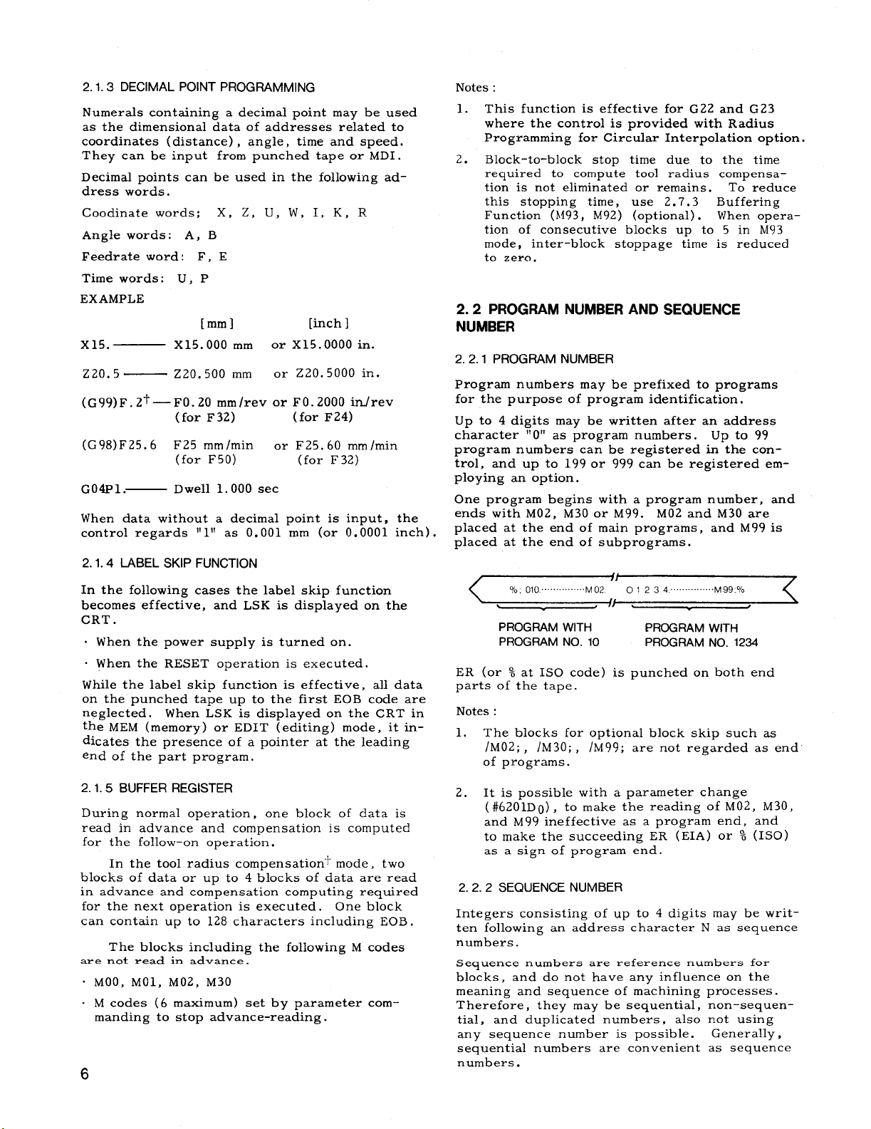
One program begins with a program number, and
ends with M02, M30 or M99. M02 and M30 are
placed at the end of main programs, and M99 is
placed at the end of subprograms.
up to 99
In the followingcases the labelskip function
becomes effective,and LSK is displayed on the
CRT .
. When the power supply is turned on.
. When the RESET operationis executed.
While the labelskip functionis effective,alldata
on the punched tape up to the firstEOB code are
neglected.
When LSK is displayed on the CRT in
the MEM (memory) or EDIT (editing)mode, itindicatesthe presence of a pointer at the leading
end of the part program.
BUFFER REGISTER
2.1.5
During normal operation, one block of data is
read in advance and compensation is computed
for the follow-on operation.
In the toolradius compensation”tmode, two
blocks of data or up to 4 blocks of data are read
in advance and compensation computing required
for the next operationis executed. One block
can contain up to 128 characters including EOB .
The blocks including the followingM codes
are not read in advance .
. MOO, MO1, M02, M30
. M codes (6 maximum) set by parameter com-
manding to stop advance-reading.
6
PROGRAM WITH
PROGRAM NO. 10 PROGRAM NO.
PROGRAM WITH
1234
ER (or % at 1S0 code) is punched on both end
parts of the tape.
Notes:
1. The blocks for optionalblock skip such as
/M02;, /M30;, /M99; are not regarded as end
of programs.
2. It is possiblewith a parameter change
(#6201Do), to make the reading of M02, M30,
and M99 ineffectiveas a program end, and
to make the succeeding ER (EIA) or % (ISO)
as a sign of program end.
SEQUENCE NUMBER
2.2.2
Integers consistingof up to 4 digitsmay be written followingan address character N as sequence
numbers.
Sequence numbers are reference numbers for
blocks, and do not have any influenceon the
meaning and sequence of machining processes.
Therefore, they may be sequential,non-sequen-
tial,and duplicated numbers , also not using
any sequence number is possible.
Generally,
sequentialnumbers are convenient as sequence
numbers.
Page 15
When searching for sequence numbers, be sure
to search or specifyprogram numbers beforehand.
Notes:
1. Five or more digitsmust not be written as a
sequence number.
2.
When two or more blocks have the same se–
quence number, only one is retrievedand
read, and no more searching is performed.
3. Blocks without sequence numbers can also
be searched for with respect to the address
data contained in the blocks.
2.2.3.
OPTIONAL BLOCK SKIP (/1-/9j+)
Those blocks in which “/n” (n = (1 - 9) is included are neglected between In and the end of
that block, when the externaloptionalblock skip
switch for that number “n” is on.
EXAMPLE
2.3.1
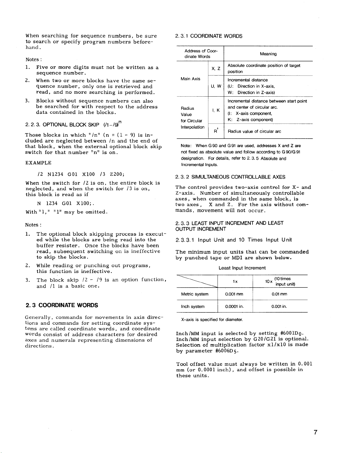
COORDINATE WORDS
Address of Coordinate Words
Absolute coordinate position of target
x, z
I I
Main Axis
Radius
Value
for Circular
Interpolation
Note: When G 90 and G 91 are used, addresses X and Z are
not fixed as absolute value and follow according to G 90/G 91
designation. For details, refer to 2.3.5 Absolute and
Incremental Inputs,
position
Incremental distance
(U: Direction in X-axis,
u. w
W: Direction in Z-axis)
Incremental distance between start point
and center of circular arc.
1, K
(1: X-axis component,
K: Z-axis component)
R+
Rsdius value of circular arc
Meaning
/2 N1234 GO1 X1OO /3 z200;
When the switch for /2 is on, the entireblock is
neglected,
and when the switch for /3 is on,
thisblock is read as if
N 1234 GO1 XIOO; .
With II1,IIIIIllmay be omitted.
Notes:
1. The optionalblock skipping process is executed while the blocks are being read intothe
buffer resister.
Once the blocks have been
read, subsequent switching on is ineffective
to skip the blocks.
2.
While reading or punching out programs,
thisfunctionis ineffective.
3. The block skip /2 - /9 is an option function,
and /1 is a basic one.
COORDINATE WORDS
2.3
Generally,
commands for movements in axis direc–
tions and commands for settingcoordinatesystems are calledcoordinatewords, and coordinate
words consistof address characters for desired
axes and numerals representing dimensions of
directions.
2.3.2 SIMULTANEOUS CONTROLLABLE AXES
The controlprovides two-axis controlfor X- and
Z-axis.
Number of simultaneouslycontrollable
axes, when commanded in the same block, is
two axes ,
Xand Z. For the axis without com-
mands, movement willnot occur.
LEAST INPUT INCREMENT AND LEAST
2.3.3
OUTPUT INCREMENT
2.3.3.1
Input Unit and 10 Times input Unit
The minimum input units that can be commanded
by punched tape or MD I are shown below.
Least Input Increment
lx
Metric system 0.00f mm O.Of
Inch system I 0.0001 in. I
X-axis is specified for diameter.
,0x (?Otimes
Input unit)
mm
0.001 in.
Inch /MM input is selectedby setting#6001D0.
Inch/MM input selectionby G20/G21 is optional.
Selectionof multiplicationfactorxl/x10 is made
by parameter #6006D
5.
Tool offsetvalue must always be written in 0.001
mm (or O.0001 inch), and offsetis possiblein
these units.
7
Page 16
2.3,3,1 Input Unit and 10 Times Input Unit
(Cent’d)
In 0.01 mm increment system, the followingoperationmust be made in the unit of O.01 mm.
. Programming for operationin TAPE mode.
o Write operationin MDI mode.
. Programming for operationin MEMORY mode.
o Program editingoperationin EDT mode .
Notes:
If NC tape programmed by O.001 mm is fed
1.
intoor stored in an equipment set by O.01
mm increment, the machine willmove ten
times the intended dimensions.
If the increment system is switched when the
2.
contents of NC tape are stored in memory,
the machine willmove by ten times or one
tenth of the commanded dimensions.
When the stored program is punched out on
3.
the tape+, the stored figures are punched
out 1!as stored!lregardlessof switching of
the increment system.
Multiplicationfactor 10X (10 times the input
4.
unit)is effectivefor distancecommand only.
Itdoes not functionon the designationof
time, angle, etc. When multiplicationfactor
10X is set as effective(#6006D5 = 1), the
same address word is multipliedby 10 or not
depending on type of G command.
EXAMPLE
G04 U...
GOO U... ;—
2.3.3.2 Least
output increment is the minimum unit of
Least
;—Not multipliedby 10 (Time)
Multipliedby 10 (Distance)
Output Increment
toolmotion. Selectionof metric system or inch
system is made by parameter (#6007D3).
Least Output Increment
I
I
I
Z-axis
0.001 mm
0.0001 in.
Metric output
Inch output
I
I
I
X-axis
(Radius value)
0.0005 mm
0.00005 in.
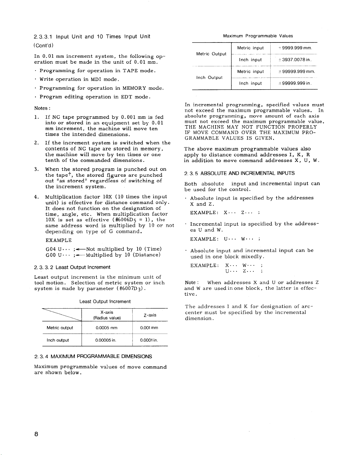
Maximum Programmable Values
Metric input
Metric Output
Inch input ~ + 3937.0078 in.
-...t -––-–.—–. -----
Metric input * 99999.999 mm.
Inch Outout
Inch input
+.9999.999 mm.
I
– + –- ——–—-—-
I
?c99999.999 in
In incrementalprogramming, specifiedvalues must
not exceed the maximum programmable values. In
absolute programming, move amount of each axis
must not exceed the maximum programmable value.
THE MACHINE MAY NOT FUNCTION PROPERLY
IF MOVE COMMAND OVER THE MAXIMUM PRO-
GRAMMABLE VALUES IS GIVEN.
The above maximum programmable values also
apply to distancecommand addresses 1, K, R
in additionto move command addresses X, U, W.
ABSOLUTE AND INCREMENTAL INPUTS
2.3.5
Both absolute
input and incrementalinput can
be used for the control.
Absolute input is specifiedby the addresses
Xand Z.
EXAMPLE: X.. . Z.. . ;
Incrementalinput is specifiedby the addresses U andw.
EXAMPLE: U,. . W.. , ;
Absolute input and incrementalinput can be
used in one block mixedly.
EXAMPLE: X.. . W.. . ;
u.. . z... ;
Note :
When addresses X and U or addresses Z
and W are used inone block, the latteris effective.
The addresses 1 and K for designationof arccenter must be specifiedby the incremental
dimension.
MAXIMUM PROGRAMMABLE DIMENSIONS
2.3.4
Maximum programmable values of move command
are shown below.
8
Page 17
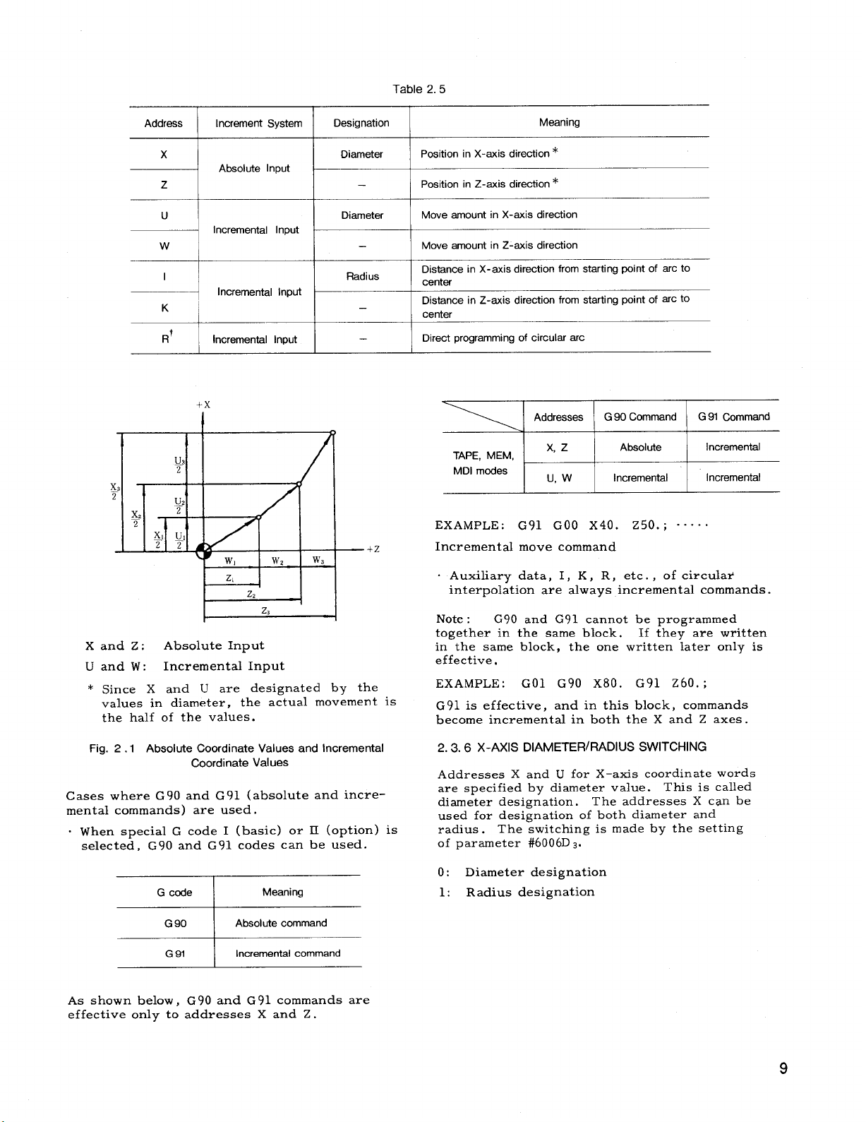
Table 2.5
Address
i
Increment System Designation
x
Absolute Input
z
u
Incremental Input
I
Incremental Input
K
R’
Incremental Input
Diameter Position in X-axis direction*
—
Diameter
—
Radius
—
—
~
Position in Z-axis direction *
Move amount in X-axis direction
Move amount in Z-axis direction
Distance in X-axis direction from starting point of arc to
center
Distance in Z-axis direction from starting point of arc to
center
Direct programmingof circular arc
TAPE, MEM,
MDI modes
EXAMPLE :
—+Z
Incrementalmove command
Meaning
Addresses G 90 Command G 91 Command
x, z Absolute Incremental
u, w Incremental
Incremental
G91 GOO X40. z50. ; ““”..
w
Xand Z: Absolute Input
Uand W:
* Since X and U are designated by the
values in diameter,the actual movement is
the half of the values.
Fig. 2.1 Absolute Coordinate Values and Incremental
Cases where G 90
mental commands ) are used.
When specialG code I (basic) or II (option)is
selected,G90 and G91 codes can be used.
Incremental Input
Coordinate Values
and G 91 (absoluteand incre-
G code
90
G
91 Incremental command
G
Meaning
Absolute command
. Auxiliarydata, I, K, R, etc., of circular
interpolationare always incrementalcommands.
Note:
together in the same block.
G90 and G91 cannot be programmed
If they are written
in the same block, the one writtenlater only is
effective,
EXAMPLE :
GO1 G90 x80. G91 z60.;
G 91 is effective,and in thisblock, commands
become incrementalin both the X and Z axes.
X-AXIS DIAMETER/RADIUS SWITCHING
2.3.6
Addresses X and U for X-axis coordinatewords
are specifiedby diameter value. This iscalled
diameter designation.
The addresses X can be
used for designationof both diameterand
radius.
of parameter #6006D
The switchingis made by the setting
3.
0: Diameter designation
1: Radius designation
As shown below, G90 and G91 commands are
effectiveonly to addresses X and Z .
9
Page 18
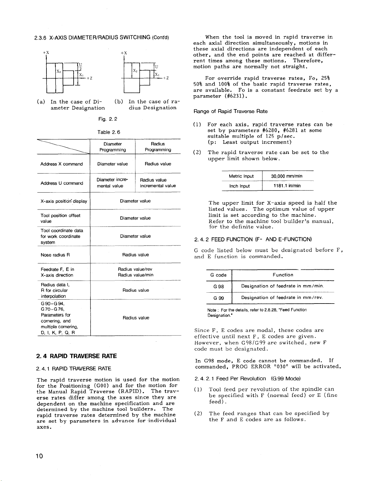
2.3.6 X-AXIS DIAMETER/RADIUS SWITCHING (Cent’d)
each axialdirectionsimultaneously,motions in
+x
+x
I
these axial directionsare independent of each
other. and the end Doints are reached at differ-
rent times among these motions.
motion paths are normally not straight.
50% and 100% of the basic rapid traveree ratee,
BEl=$+zEF+z
(a) In the case of Di-
ameter Designation dius Designation
Address X command
(b) In the case of ra-
-.-f,
r-lg. z. z
Table 2.6
Diameter
Programming
Radius
Programming
are available.
parameter (#6231).
Range of Rapid Traverse Rate
(1)
(2) The rapid traverse rate can be set to the
When the toolis moved in rapid traversein
“.
.
Therefore,
For override rapid traverse rates, Fo, 25%
Fo is a constant feedrateset by
For each axis, rapid traverse rates can be
set by parameters #6280, #6281 at some
suitablemultipleof 125 p/see.
Least output increment)
(p:
uPPer limitshown below.
a
Address U command
X-axis position-display
Tool position offset
value
Tool coordinate data
for work coordinate
system
Nose radius R
Feedrate F, E in
X-axis direction
Radius data 1,
R for circular
interpolation
G90-G 94,
G70-G76,
Parameters for
cornering, and
multiple cornering,
D, 1, K, P, Q, R
Diameter value
Diameter value
Diameter value
Radius value
Radius value/rev
Radius value/rein
Radius value
Radius value
2.4 RAPID TRAVERSERATE
2.4.1RAPID TRAVERSE RATE
The rapid traverse motion is used for the motion
for the Positioning(GOO ) and for the motion for
the Manual Rapid Traverse (RAPID). The traverse rates differamong the axes since they are
dependent on the machine specificationand are
determined by the machine toolbuilders.
The
rapid traverse rates determined by the machine
are set by parameters in advance for-individual
axes.
~
The upper limitfor X-axis speed is halfthe
listedvalues. The optimum value of upper
limitis set according to the machine.
Refer to the machine toolbuilder’smanual,
for the definitevalue.
FEED FUNCTION (F- AND E-FUNCTION)
2.4.2
code listedbelow must be designated before F,
G
and E functionis commanded.
Designation of feedrate in mm/min.
~
Note: Forthsdetails,referto2.8.28, “FeedFunction
Designation.”
Designation of feedrate in mm/rev.
Since F, E codes are modal, these codes are
effectiveuntilnext F , E codes are given.
However, when G98/G99 are switched, new F
code must be designated.
In G98 mode, E code cannot be commanded. If
commanded, PROG ERROR “030” willbe activated.
2.4.2.1
(1)
Feed Per Revolution (G99 Mode)
Tool feed per revolutionof the spindlecan
be specifiedwith F (normal feed) or E (fine
feed).
(2) The feed ranges that can be specifiedby
the F and E codes are as follows.
10
Page 19
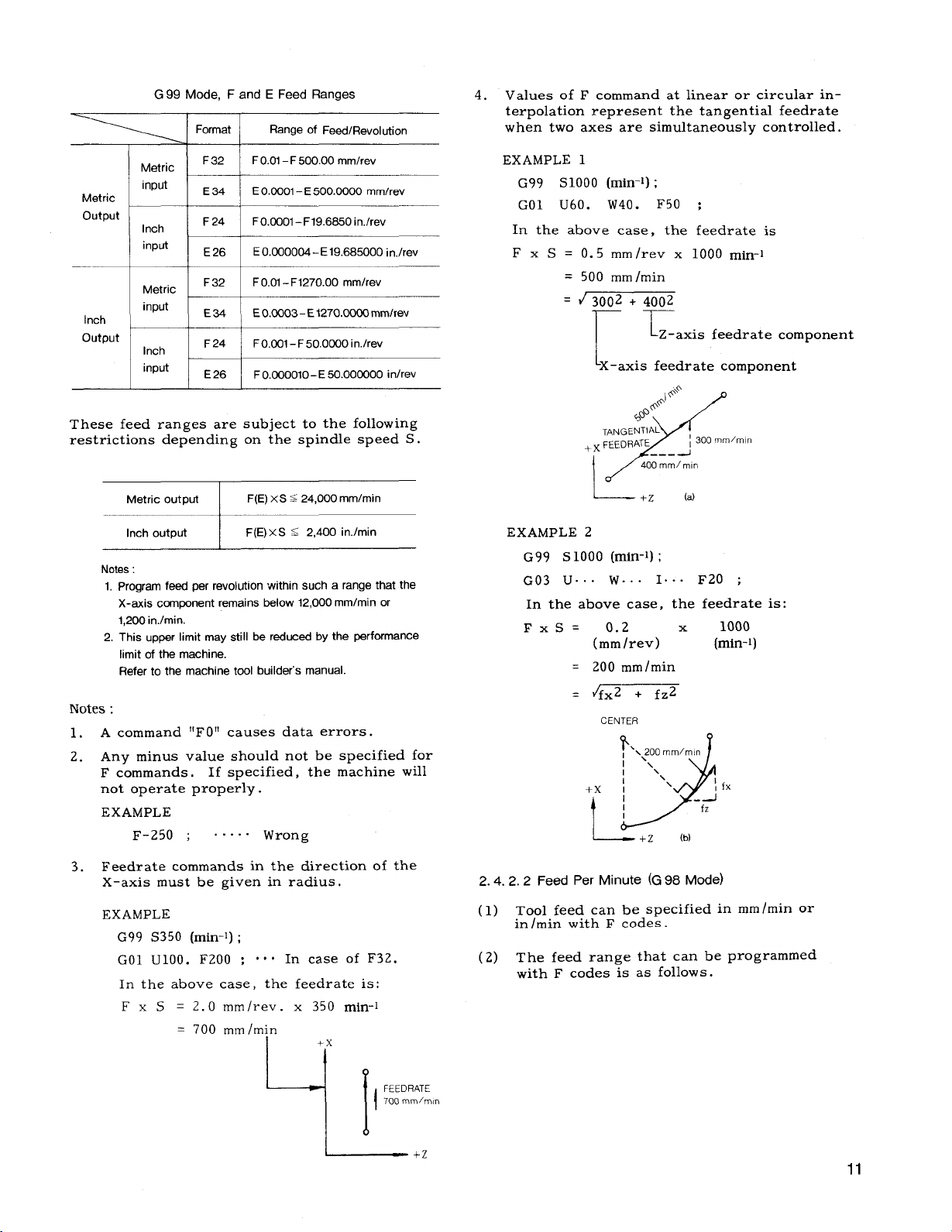
G99 Mode, Fand E Feed Ranges
‘~ I Format I Range of Feecf/Revel.tion
4.
Values of F command at linearor circularinterpolationrepresent the tangentialfeedrate
when two axes are simultaneouslycontrolled.
Metric
1
Metric
output
Inch
output
These feed ranges are subjectto the following
restrictionsdepending on the spindlespeed S.
lVotes :
1.
2.
input
Inch
i
input
I
Metric
‘nPut1+=~
Inch
input
Metric output
Inch output
Notes:
1. Program feed per revolution within such a range that the
X-axis ccwnponentremains below 12,000 mm/min or
1,200 in./min.
2.
This upper limit may still be reduced by the performance
limit of the machine.
Refer to the machine tool builder’s manual.
A command “F O“ causes data errors.
Any minus value should not be specifiedfor
F commands.
not operate properly.
EXAMPLE
F-250 ; s““”” Wrong
F 32
E34
F 24
E 26
I
F24 FO.001–F 50.0000 in./rev
E26
F0.01– F 500.00 mmlrev
I
E0.0001 – E 500.0000 mmfrev
FO.CQOI–F19.6850 in./rev
E0.C00004 – E 19.685000
~
F O.OQOO1O–E 50.000000 in/rev
F(E)XS S 24,000 mmlmin
F(E)XS S 2,400 in./min
If specified,the machine will
—.
in.lrev
EXAMPLE 1
G99 S1OOO (rein-l);
GO1 U60. W40. F50 ;
In the above case, the feedrate is
F x S = 0.5 mm/rev x 1000 rein-l
= 500 mm/min
~ 3002 + 4002
——
1
!
Z-axis feedratecomponent
[~_axisfeedrate component
I$’$’
@+
@
TANGENTIAL
+x FEEDRATE
X
I
J
L-
EXAMPLE 2
G99 S 1000 (rein-l);
G03 U.. . W.. . 1.
In the above case,
FxS= 0.2
(mm/rev)
= 200 mm/min
Jfx2 + fz2
=
CENTER
}
,‘1.200
I
I x,
+x I
t ! 7-’:
~ +Z
400 mm/mln
+Z
‘\
~ 300 mm/mln
---
(a)
.. F20 ;
the feedrateis:
1000
x
(rein-l)
mm/mtn
\\.
f!fx
‘d”
(b)
Feedrate commands in the directionof the
3.
X-axis must be given in radius.
EXAMPLE
G99 S350 (rein-l);
GO1 U1OO. F200 ;
In the above case, the feedrateis:
F x S = 2.0 mm/rev. x 350 rein-l
= 700 mm /rein
000 In case of F3Z.
+x
9[
L___ +,
FEEDRATE
700 mmlmm
I
2.4.2.2
(1) Tool feed can be specifiedin
(2) The feed range that can be programmed
Feed Per Minute (G98 Mode)
mm /reinor
in/reinwith F codes.
with F codes is as follows.
11
Page 20
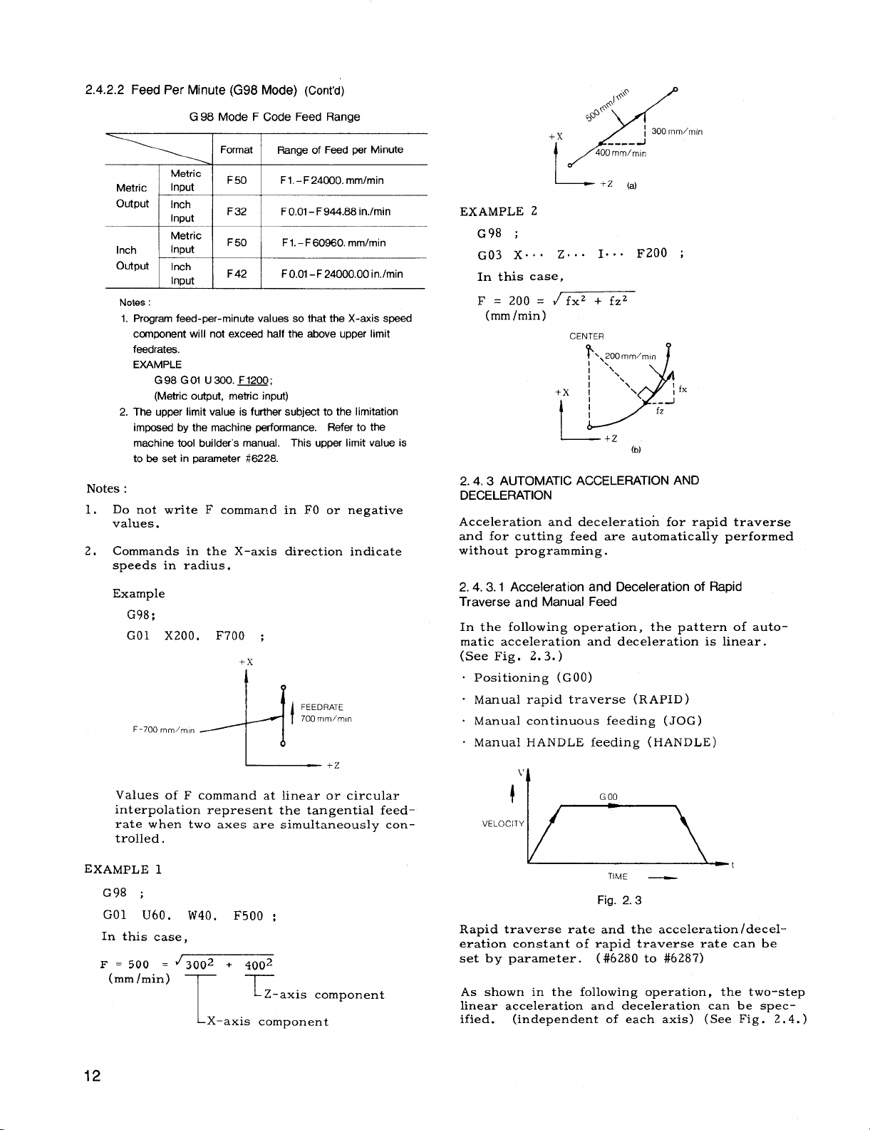
2.4.2.2 Feed Per Minute (G98 Mode) (Cent’d)
‘ELO’:ln
G98 Mode FCode
% lFormatl Range of Feedpar Min.te
Metric
Intwt
I
Metric
output
Inch
output
Notes:
1. Program feed-per-minute values so that the X-axis speed
2. The upper limit value is further subject to the limitation
Notes:
Do not write F command in FO or negative
1.
values.
2. Commands in the X–axis directionindicate
speeds in radius.
Example
G98;
GO1 X200. F700 :
Inch
I
Irmut
Metric
Input
i
Inch
hlDut
~
ccmponent wiIi not exceed half the above upper limit
faedrates.
EXAMPLE
G98 GOI U300. F1200
(Metric output, metric input)
imposed by the machine performance. Refer to the
machine tool buiIder’s manual, This upper limit value is
to be set in Daremeter #8228.
F=700mm/m, n
F50
I
F32
I
F 50
I
F 42
I
—!
+x
’13-
FeedRange
F1.– F 24000. mm/min
~
F0.01–F944.88 in.lmin
1
F1.– F60860. mmlmin
1
FO.01–F 24000.00 in,lmin
I
FEEDRATE
700 mm/mln
1
+Z
*I @o
~@
&
+x
400mm/mln
/
L
EXAMPLE 2
G98 ;
G03 X.. . Z... 1“”” F200 ;
In this case,
F= 200= {fx2 +fz2
(mm/min)
+x I
2.4.3
AUTOMATIC ACCELERATION AND
DECELERATION
Accelerationand decelerationfor rapid traverse
and for cutting feed are automaticallyperformed
without programming.
2.4.3.1 Acceleration and Deceleration of Rapid
Traverse and Manual Feed
In the followingoperation,the pattern of auto-
matic accelerationand decelerationis linear.
(See Fig, 2.3,)
. Positioning(GOO)
“ Manual rapid traverse (RAPID)
. Manual continuous feeding (JOG)
. Manual HANDLE feeding (HANDLE)
CENTER
?’.\,oomm/m(”
1,
9
I
-
+ z (a)
/ 300mm/m[n
-----J
‘\\
+-Z
J
\
;fx
\
J
-c
(b)
Values of F command at linearor circular
interpolationrepresent the tangentialfeed–
rate when two axes are simultaneouslycontrolled.
EXAMPLE 1
G98 ;
GO1 u60, W40. F500 ;
In thiscase,
500 . ~3002 . 4002
F =
(mm/min)
T
T
Z-axis component
X-axis component
TIME _
Fig. 2.3
Rapid traverse rate and the acceleration/decel-
erationconstant of rapid traverse rate can be
set by parameter. (
As shown in the followingoperation,the two-step
linearaccelerationand decelerationcan be specified. (independent of each axis) (See Fig. 2.4.)
#6280 to #6287)
Page 21
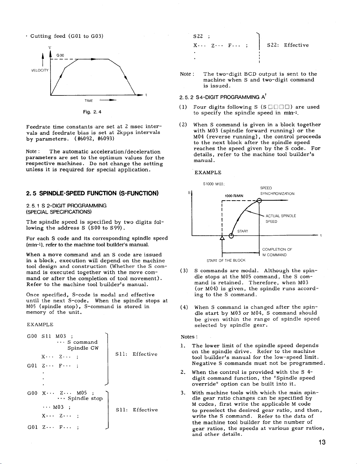
. Cutting feed (GO1 to G03)
v
G00
.———
L
t
VELOCITY
TIME —
Fig. 2.4
S22 ;
X.. .
z.. F.. . ;
S22: Effective
1
Note : The two-digitBCD output is sent to the
machine when S and two–digitcommand
is issued.
t
2.5.2 S4-DIGIT
PROGRAMMING AT
(1) Four digitsfollowingS (S El❑ ❑ •l) are used
to specify the spindle speed in rein-l.
Feedrate time constants-areset at 2 msec intervals and feedrate bias is set at 2kpps intervals
by parameters. (
#6092, #6093)
Note: The automaticacceleration/deceleration
parameters are set to the optimum values for the
respective machines.
Do not change the setting
unless itis required for specialapplication.
SPINDLE-SPEED FUNCTION (S-FUNCTION)
2.5
2.5.1 S 2-DIGIT PROGRAMMING
(SPECIAL
SPECIFICATIONS)
The spindlespeed is specifiedby two digitsfol-
lowing the address S (S00 to S
99) .
For each S code and itscorrespondingspindlespeed
(rein-l),refertothemachinetoolbuilder’smanual.
When a move command and an S code are issued
in a block, execution willdepend on the machine
tooldesign and construction (Whether the S command is executed together with the move com-
mand or afterthe completionof toolmovement) .
Refer to the machine toolbuilder’smanual.
Once specified,S-code is modal and effective
untilthe next S-code.
When the spindlestops at
M05 (spindlestop), S-command is stored in
memory of the unit.
EXAMPLE
(2) When S command is given in a block together
with M03 (spindle forward running) or the
M04 (reverse running) , the controlproceeds
to the next block afterthe spindle speed
reaches the speed given by the S code. For
details,refer to the machine toolbuilder’s
manual.
EXAMPLE
S1OOO M03,
s
I
START OF THE BLOCK
S commands are modal. Although the spin-
(3)
1003 R/MIN
———— —-
11
I
I
I
‘fl
I
u
%
START
SPEED
SYNCHRO)
ACTUAL
SPEED
dlZATION
SPINDLE
~::::fi”’
dle stops at the M05 command, the S command is retained.
Therefore, when M03
(or M04) is given, the spindleruns accord-
ing to the S command.
(4)
When S command is changed afterthe spin-
dle startby M03 or M04, S command should
be given within the range of spindle speed
selectedby spindle gear.
t
GOO S11 M03 ;
... S command
Spindle CW
x.. . z... ;
GO1 Z.. . F.. . ;
GOO X.. . z... M05 ;
.,. Spindle stop
...M03 ;
x.. . z.. . ;
... ...
F
z
GO
;
Sll: Effective
S 11: Effective
Notes:
The lower limitof the spindle speed depends
1.
on the spindle drive.
Refer to the machir,e
toolbuilder’smanual for the low-speed limit.
Negative S commands must not be programmed.
2.
When the control is provided with the S 4digitcommand function,the “Spindle speed
override” option can be builtintoit.
3.
With machine toolswith which the main spin-
dle gear ratiochanges can be specifiedby
M codes, firstwrite the applicableM code
to preselectthe desired gear ratio,and then,
write the S command. Refer to the data of
the machine toolbuilder for the number of
gear ratios,the speeds at various gear ratios,
and other details.
13
Page 22
2.5.2 S 4-DIGIT PROGRAMMING At (Cent’d)
When the controlis provided with this func-
4.
tion,the spindlemaximum speed commanding
functionwith the instruction“G50 S. .. ;”
can be used.
2.5.3S 4-DIGIT
PROGRAMMING Bf
(1) This functionis to modify the S4-digitcom-
mand A output freelythrough the program–
mable machine interface.
(2) Basically,thisfunctionisusedin thesame way as
theS 4-digitcommand A function,but itisnormallyused tosetthemanuallycontrolledspindle
speeds controlledby the rotaryswitchon the
machine controlstationcorrespondingto S command speeds.
For the detailsofS command
speeds,refertothemachinetoolbuilder’smanual.
TOOL FUNCTION (T-FUNcTiON)
2.6
2,6.1 T 4-DIGIT PROGRAMMING
(1) Four digitsfollowingthe address T specifies
the toolnumber.
OFFSET MEMORY NO
x
‘ WORK COORDINATE
SHIFT MEMORY
(1 GROUP)
‘TOOL OFFSET
MEMORY —
(50 GROUPS MAX)
‘TOOL COORDINATE
MEMORY —
(49 GROUPS MAX)
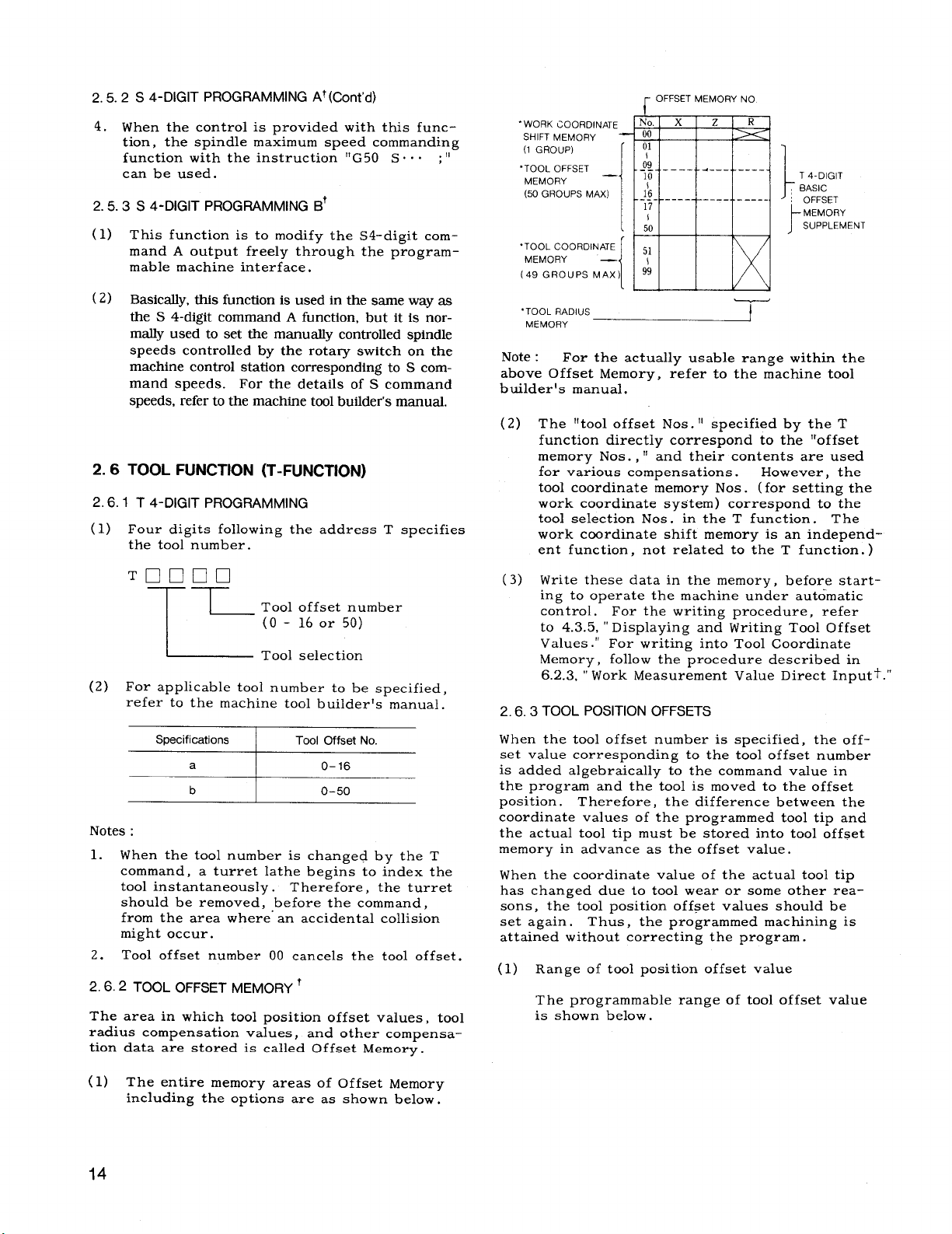
Note :
For the actuallyusable range within the
No.
00
01
;9
--- ------ -4- —-.
y
J.
______
I ‘
50
51
99
[ ‘
_____
z R
-----
-----
-‘
T 4-DIGIT
; BASIC
: OFFSET
MEMORY
SUPPLEMENT
F
above OffsetMemory, refer to the machine tool
builder’smanual.
(2) The “tooloffsetNos. “ specifiedby the T
functiondirectlycorrespond to the “offset
memory Nos. ,“ and theircontents are used
for various compensations.
However, the
toolcoordinatememory Nos. (for settingthe
work coordinatesystem) correspond to the
toolselectionNos. in the T function. The
work coordinateshiftmemory is an independent function,not relatedto the T function.)
Tnmmn
TC(o_160r50)
Tool offsetnumber
Tool selection
(2) For applicabletoolnumber to be specified,
refer to the machine toolbuilder’smanual.
Notes:
1.
When the toolnumber is changed by the T
command, a turret lathe begins to index the
toolinstantaneously.
Therefore, the turret
should be removed, before the command,
from the area where”an accidentalcollision
might occur.
Tool offsetnumber 00 cancelsthe tooloffset.
2.
TOOL OFFSET MEMORY t
2,6.2
The area in which toolpositionoffsetvalues, tool
radius compensation values, and other comPensa–
tiondata are stored is calledOffset Memory.
(3) Write these data in the memory, before start-
ing to operate the machine under automatic
control. For the writing procedure, refer
to 4.3.5,“Displaying and WritingTool Offset
Values.“
For writingintoTool Coordinate
Memory, followthe procedure described in
6.2.3,“Work Measurement Value DirectInputt.“
TOOL POSITION OFFSETS
2.6.3
When the tooloffsetnumber is specified,the off-
set value corresponding to the tooloffsetnumber
is added algebraicallyto the command value in
the program and the toolis moved to the offset
position. Therefore, the differencebetween the
coordinatevalues of the programmed tooltipand
the actualtooltip must be stored intotooloffset
memory in advance as the offsetvalue.
When the coordinatevalue of the actualtooltip
has changed due to toolwear or some other rea-
sons, the toolpositionoffsetvalues should be
set again.
Thus, the programmed machining is
attainedwithout correctingthe program.
(1) Range of tool positionoffsetvalue
The programmable range of tooloffsetvalue
is shown below.
(1) The entirememory areas of Offset Memory
including the options are as shown below.
14
Page 23
output I
Metric
output
Inch
output
(2)
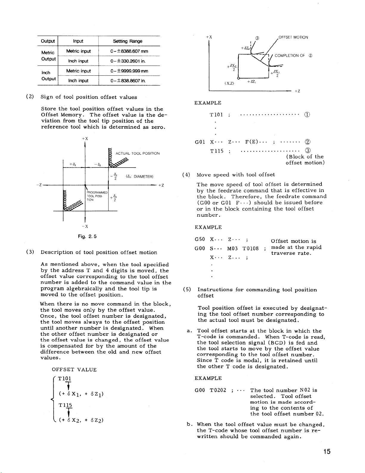
Sign of toolpositionoffsetvalues
Store the toolpositionoffsetvalues in the
OffsetMemory.
viationfrom the tooltippositionof the
reference toolwhich is determined as zero.
Input
Metric input O- k6366.607
Inch input O–+330.260t in.
Metric input O– ~9999.999 mm
Inch input O- t636.t?607 in.
The offsetvalue is the de-
I
setting Range
mm
+x
,’+
8X3
+
2
X,z)
(
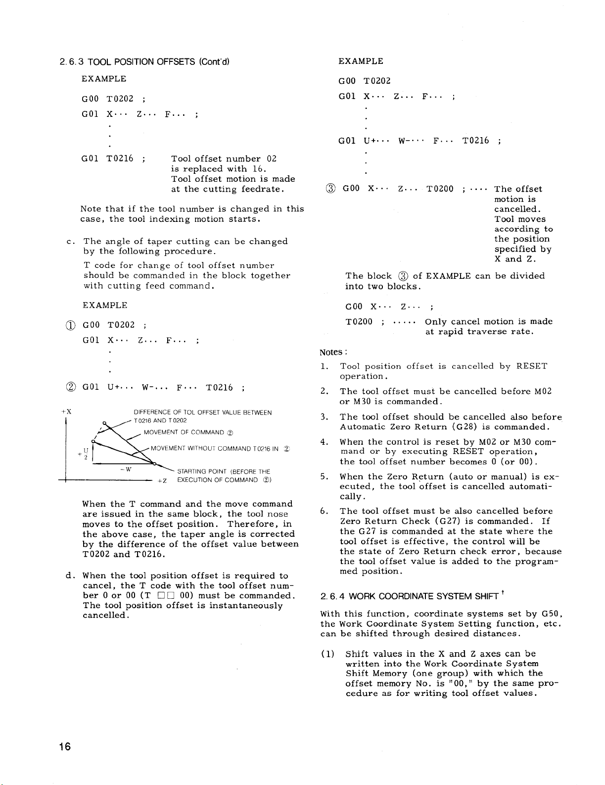
EXAMPLE
TIOI ; ....................
CIZ2:
+
+Sz,
(2
‘- 1 COMPLETION
,OFFSET MOTION
--
ax!
+
2
o
+x
tiOLpOs’T’ON
-z
I
Descriptionof toolpositionoffsetmotion
(3)
As mentioned above,
by the address T and 4 digitsis moved, the
offsetvalue corresponding to the tooloffset
number is added to the command value in the
program algebraicallyand the tooltipis
moved to the offsetposition.
When there is no move command in the block,
the toolmoves only by the offsetvalue.
Once, the tooloffsetnumber is designated,
the toolmoves always to the offsetposition
untilanother number is designated. When
the other offsetnumber is designated or
the offsetvalue is changed, the offsetvalue
is compensated for by the amount of the
differencebetween the old and new offset
values.
OFFSET VALUE
T101
T
(+ 6X1, + 6Z1)
[
T115
T
(+ 6X2, + 6Z2)
[
I I
PROGRAMMED
–x
Fig. 2.5
8
.2
(& DIAMETER)
2
when the toolspecified
+-z
GO1 X.. . Z...
T115 ; ....................
(4) Move speed with tooloffset
The move speed of tooloffsetis determined
by the feedratecommand that is effectivein
the block. Therefore, the feedratecommand
(GOO or GO1 F.
or in the block containingthe tooloffset
number.
EXAMPLE
G50 X.. . Z.. . ;
GOO S.. . M03 TO1O8 ;
x.. . z... ;
(5)
Instructionsfor commanding toolposition
offset
Tool positionoffsetis executed by designating the tooloffsetnumber corresponding to
the actual toolmust be designated.
a.
Tool offsetstartsat the block in which the
T-code is commanded. When T-code is read,
the tool selectionsignal (BCD ) is fed and
the toolstartsto move by the offsetvalue
corresponding to the tooloffsetnumber.
Since T code is modal, itis retaineduntil
the other T code is designated.
EXAMPLE
GOO T0202 ; ...
b.
When the tooloffsetvalue must be changed,
the T-code whose tooloffsetnumber is rewritten should be commanded again.
F(E) ... ; .......
(Block of the
offsetmotion)
..) should be issued before
Offset
made at the rapid
traverse rate.
The toolnumber N02 is
selected.
motion is made accord–
ing to the contents of
the tooloffsetnumber 02.
motion is
Tool offset
@
@
15
Page 24
2.6.3 TOOL POSITION OFFSETS (Cent’d)
EXAMPLE
EXAMPLE
GOO T0202 ;
GO1 X.. . ZOO. F.. . ;
GO1 T0216 ;
Tool offset
isreplaced
Tool offset
at the cutting feedrate.
number 02
with 16.
motion is made
Note that ifthe toolnumber is changed in this
case, the toolindexing motion starts,
c. The angle of taper cutting can be changed
by the followingprocedure.
T code for change of tooloffsetnumber
should be commanded in the block together
with cuttingfeed command .
EXAMPLE
@ GOO T0202 ;
GO1 X.. . Z... F... ;
@GOl U+... W-... F... TI)216 ;
+x
,
/
.U
2
la
DIFFERENCE OF TOL OFFSET VALUE BETWEEN
T0216 AND T 0202
MOVEMENT OF COMMAND ~~
MOVEMENT WITHOUT COMMAND T0216 IN c
–w
STARTING POINT (BEFORE THE
EXECUTION OF COMMAND @)
~z
When the T command and the move command
are issued in the same block, the toolnose
moves to the offsetposition. Therefore, in
the above case, the taper angle is corrected
by the differenceof the offsetvalue between
T0202 and T0216.
d.
When the toolpositionoffsetisrequired to
cancel,the T code with the tooloffsetnum–
ber O or 00 (T ❑ 0 00) must be commanded.
The toolpositionoffsetisinstantaneously
cancelled.
GOO T0202
...
GO1 X.. . Z...
Gol
u+. . . w-.
@GOO X... Z..
F
. F.. .
;
T0216
T0200 ;. ...
,
The offset
motion is
cancelled.
Tool moves
according to
the position
specifiedby
Xand Z.
The block @ of EXAMPLE can be divided
intotwo blocks.
GOO X.. . Z.. . ;
. .
T0200 ; ..
only cancel motion is made
at rapid traverse rate.
Notes:
Tool position
1.
offsetis cancelledby RESET
operation.
2.
The tooloffsetmust be cancelledbefore Mf)2
or M30 is commanded.
The tooloffsetshould be cancelled alsobefore
3.
Automatic Zero Return (G28) is commanded.
When the controlis reset by M02 or M30 com-
4.
mand or by executing RESET operation,
the tooloffsetnumber becomes O (or 00).
When the Zero Return (autoor manual) is ex-
5.
ecuted, the tooloffsetis cancelledautomatically.
The tooloffsetmust be alsocancelledbefore
6.
Zero Return Check (G27) is commanded. I’f
the G27 is commanded at the statewhere the
tooloffsetis effective,the controlwillbe
the stateof Zero Return check error, because
the tooloffsetvalue is added to the programmed position.
WORK COORDINATE SYSTEM SHIFT+
2.6.4
With thisfunction,coordinatesystems set by G 50,
the Work Coordinate System Setting function, etc.
can be shiftedthrough desired distances.
(1) Shiftvalues in the X and Z axes can be
written intothe Work Coordinate System
ShiftMemory (one group ) with which the
offsetmemory No. is ,
!!00 !!by the same pro-
cedure as for writingtooloffsetvalues.
Page 25
(2)
The written shiftvalues become effective
from the moment described below.
When G50 coordinatesystem is set
a.
When G50GT work coordinatesystem is set
b.
When automaticcoordinatesystem is set
c.
PositionAbsolute displayis reset by ORG
d.
key
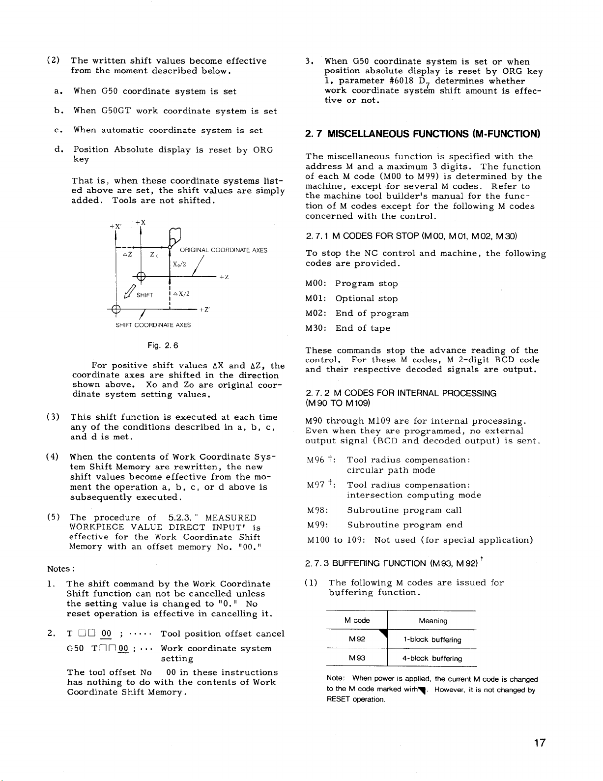
That is, when these coordinate systems listed above are set, the shiftvalues are simply
added.
Tools are not shifted.
‘N+
z,
II
ORIGINAL COORDINATE AXES
I
/
x,/2 /
3. When G50 coordinate system is set or when
positionabsolutedisplayis reset by ORG key
1, parameter #6o18 D7 determines whether
work coordinatesystem shiftamount is effectiveor not.
2.7
MISCELLANEOUS FUNCTIONS (M-FUNCTION)
The miscellaneousfunctionis specifiedwith the
address M and a maximum 3 digits. The function
of each M code (MOO to M99) is determined by the
machine, except for severalM codes.
the machine toolbuilderfsmanual for the func–
tionof M codes except for the followingM codes
concerned with the control.
M CODES FOR STOP (M 00, M 01, M 02, M 30)
2.7.1
To stop the NC controland machine, the following
codes are provided.
Refer to
+-#----+z
SHIFT COORDINATE AXES
Fig. 2.6
For positiveshiftvalues AX and AZ, the
coordinateaxes are shiftedin the direction
shown above. Xo and Zo are originalcoordinate system settingvalues.
This shiftfunctionis executed at each time
(3)
any of the conditionsdescribed in a, b, c,
and d is met.
When the contents of Work Goordinate Sys-
(4)
tem ShiftMemory are rewritten, the new
shiftvaluesbecome effectivefrom the moment the operation a, b, c, or d above is
subsequently executed.
(5)
The ~rocedure of 5.2.3.“ MEASURED
WOR.K’PIECE VALUE DIRECT INPUTi’ is
effectivefor the Work Coordinate Shift
Memory with an offsetmemory No. “00.“
Notes:
1. The shiftcommand by the Work Coordinate
Shift function can not be cancelledunless
the setting value is changed to “O.“ No
resetoperationis effectivein canceling it.
Moo:
MOl: Optionalstop
M02:
M30:
These commands stop the advance reading of the
control.
and their respectivedecoded signalsare output.
(M 90 TO M 109)
M90
Even when they are programmed, no external
output signal(BCD and decoded output) is sent.
2.7.3
(1) The followingM codes are issued for
Program stop
End of program
End of tape
For these M codes,
M CODES FOR INTERNAL PROCESSING
2.7.2
through M109 are forinternalprocessing.
M96 t:
M97 ‘:
M98:
M99:
M1OO to
Tool radius compensation:
circularpath mode
Tool radius compensation:
intersectioncomputing mode
Subroutine program call
Subroutine program end
Not used (for specialapplication)
109:
BUFFERING FUNCTION (M93, M 92) +
buffering function.
M 2-digitBCD code
2.
Tt1000 ; .....
G50 TaCl~; ...
The tooloffsetNo
has nothing to do with the contents of Work
Coordinate ShiftMemory.
—
Tool positionoffsetcancel
Work coordinate system
setting
00 in these instructions
=
Note: When power is applied, the current M code is changed
to the M code marked wirh~. However, it is not changed by
RESET ooeration.
17
Page 26
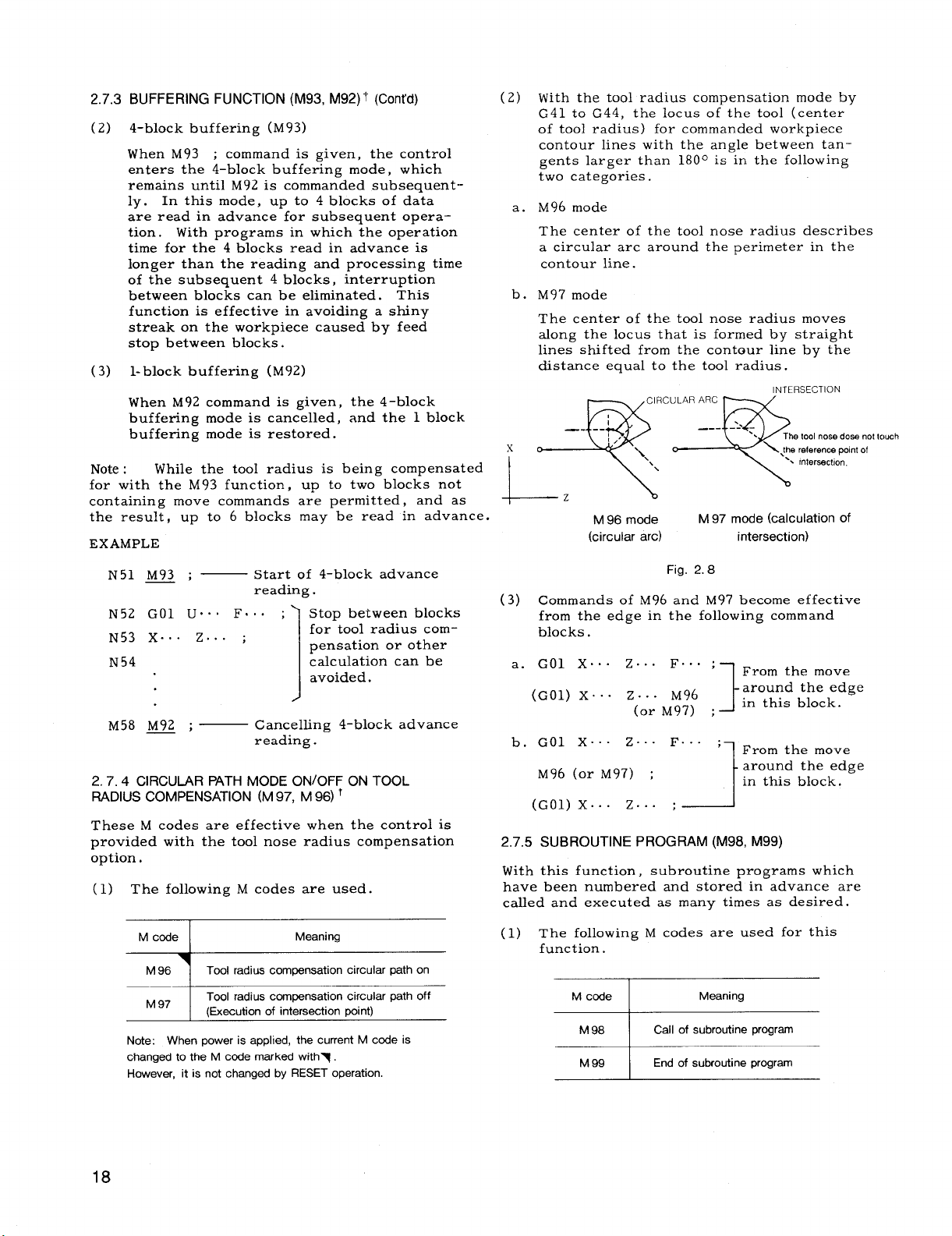
2.7.3 BUFFERING FUNCTION (M93, M92) t (Cent’d)
4-block buffering (M93)
(2)
When M93
; command is given, the control
enters the 4–block buffering mode, which
remains untilM92 is commanded subsequent-
In this mode, up to 4 blocks of data
ly.
are read in advance for subsequent opera–
tion. With programs in which the operation
time for the 4 blocks read in advance is
longer than the reading and processing time
of the subsequent 4 blocks, interruption
between blocks can be eliminated. This
function is effectivein avoiding a shiny
streak on the workpiece caused by feed
stop between blocks.
(3) l-blockbuffering (M92)
When M92 command is given, the 4-block
buffering mode is cancelled,and the 1 block
buffering mode isrestored.
Note: While the toolradius is being compensated
for with the M93 function, up to two blocks not
containingmove commands are ~ermitted, and as
the result,up to 6 blocks may-be read in advance.
EXAMPLE
N51 M93 ;
— Start of 4–block advance
reading .
N52 GO1 U“. . F.. . ;
N53 X.. . 2... ;
N54
Stop between blocks
for toolradius compensationor other
calculationcan be
avoided.
1
M58~ ;—
Canceling 4-blockadvance
reading.
CIRCULAR PATH MODE ON/OFF ON TOOL
2.7.4
RADIUS COMPENSATION (M 97, M 96)+
These M codes are effectivewhen the control is
provided with the toolnose radius compensation
option.
(1) The followingM codes are used.
(2)
With the toolradius compensation mode by
G41 to G44, the locus of the tool(center
of toolradius) for commanded workpiece
contour lineswith the angle between tangents larger than 180° is in the following
two categories.
M96 mode
a.
The center of the toolnose radius describes
a circulararc around the perimeter in the
contour line.
b.
M97 mode
The center of the toolnose radius moves
along the locus that is formed by straight
linesshifted from the contour lineby the
distanceequal to the toolradius.
x
‘“m
L
mode
M 96
(circular arc)
(3) Commands of M96 and M97 become effective
from the edge in the followingcommand
blocks.
a. GO1 X.. . 2.. . F.. . o
(GO1) X... Z... M96
(or M97) ;
b, GO1 X.. . Z... F...
M96 (orM97) ;
(GO1)
X... 2.. .
2.7.5SUBROUTINE PROGRAM (M98, M99)
With thisfunction,
subroutine programs which
have been numbered and stored in advance are
calledand executed as many times as desired.
M 97 mode (calculation of
intersection)
Fig. 2.8
From the move
‘ 1
around the edge
in thisblock.
-1-
;~ From the move
around the edge
in thisblock.
t
;--_J
M code
7
M 96
M 97
Note: When power is applied, the current M code is
changed to the M code marked withy.
However, it is not changed by RESET operation.
Tool radius compensation circular path on
Tool radius compensation circular path off
I
(Execution of intersection Doint)
Meaning
18
(1) The followingM codes are used for this
function.
Page 27
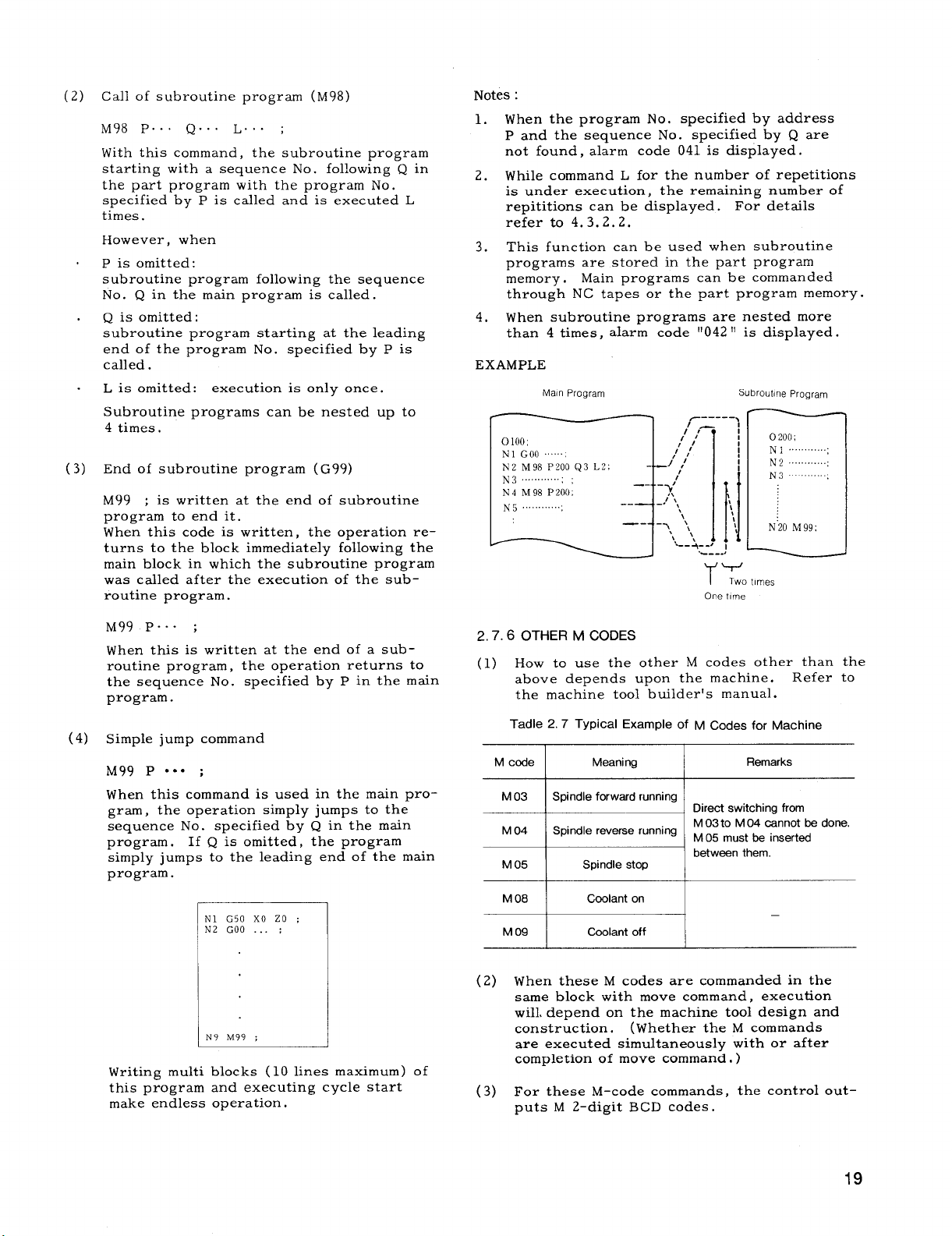
(2) Callof subroutine program (M98)
M98 P.. . Q.. . L.. . ;
With thiscommand, the subroutine program
startingwith a sequence No. followingQ in
the part program with the program No.
specifiedby P is calledand is executed L
times.
However, when
P is omitted:
subroutine program followingthe sequence
No. Q in the main program iscalled.
Q is omitted:
subroutine program startingat the leading
end of the program No. specifiedby P is
called.
L is omitted:
execution isonly once.
Subroutine programs can be nested up to
4 times.
(3) End of subroutine program (G99)
; iswritten at the end of subroutine
M99
program to end it.
When thiscode is written,the operationreturns to the block immediatelyfollowingthe
main block in which the subroutine program
was calledafterthe execution of the sub–
routineprogram.
Notes:
1. When the program No. specifiedby address
P and the sequence No. specifiedby Q are
not found, alarm code 041 is displayed.
2.
While command L for the number of repetitions
is under execution,
the remaining number of
repititionscan be displayed. For details
refer to 4.3.2.2.
3. This functioncan be used when subroutine
programs are stored in the part program
memory.
Main programs can be commanded
through NC tapes or the part program memory.
4,
When subroutine programs are nested more
than 4 times,alarm code “042“ is displayed.
EXAMPLE
Main Program
Subroutine Program
N’20M99;
I Two t[mes
One time
M99 P.. . ;
When thisis written at the end of a subroutineprogram, the operationreturns to
the sequence No.
specifiedby P in the main
program.
(4) Simple jump command
M99 P
● *o ;
When this command is used in the main pro-
gram, the operation simply jumps to the
sequence No.
specifiedby Q in the main
program . If Q is omitted,the program
simply jumps to the leading end of the main
program.
N1 G50XO ZO :
N2 GOO . . . ;
N9 M99 ;
1 1
Writingmultiblocks (10 linesmaximum) of
this program and executing cycle start
make endless operation.
2.7.6 OTHER M CODES
(1) How to use the other M codes other than the
above depends upon the machine.
Refer to
the machine toolbuilder’smanual.
Tadle 2.7 Typical Example of M Codes for Machine
M code
I
~q .ire.s.i,.hiw~.m
M 04 Spindle reverse running
Meaning
I
M 03 to M 04 cannot be done.
1
M 05 must be inserted
Remarks
-d= betw=n’hem
M 08
M 09
(2)
When these M codes are commanded in the
same block with move command, execution
wiH,depend on the machine tooldesign and
construction.
are executed simultaneouslywith or after
completion of move command. )
For these M–code commands,
(3)
puts M 2-digitBCD codes.
I
I
I
Coolant on
Coolant off
I
I
(Whether the M commands
—
the controlout-
19
Page 28
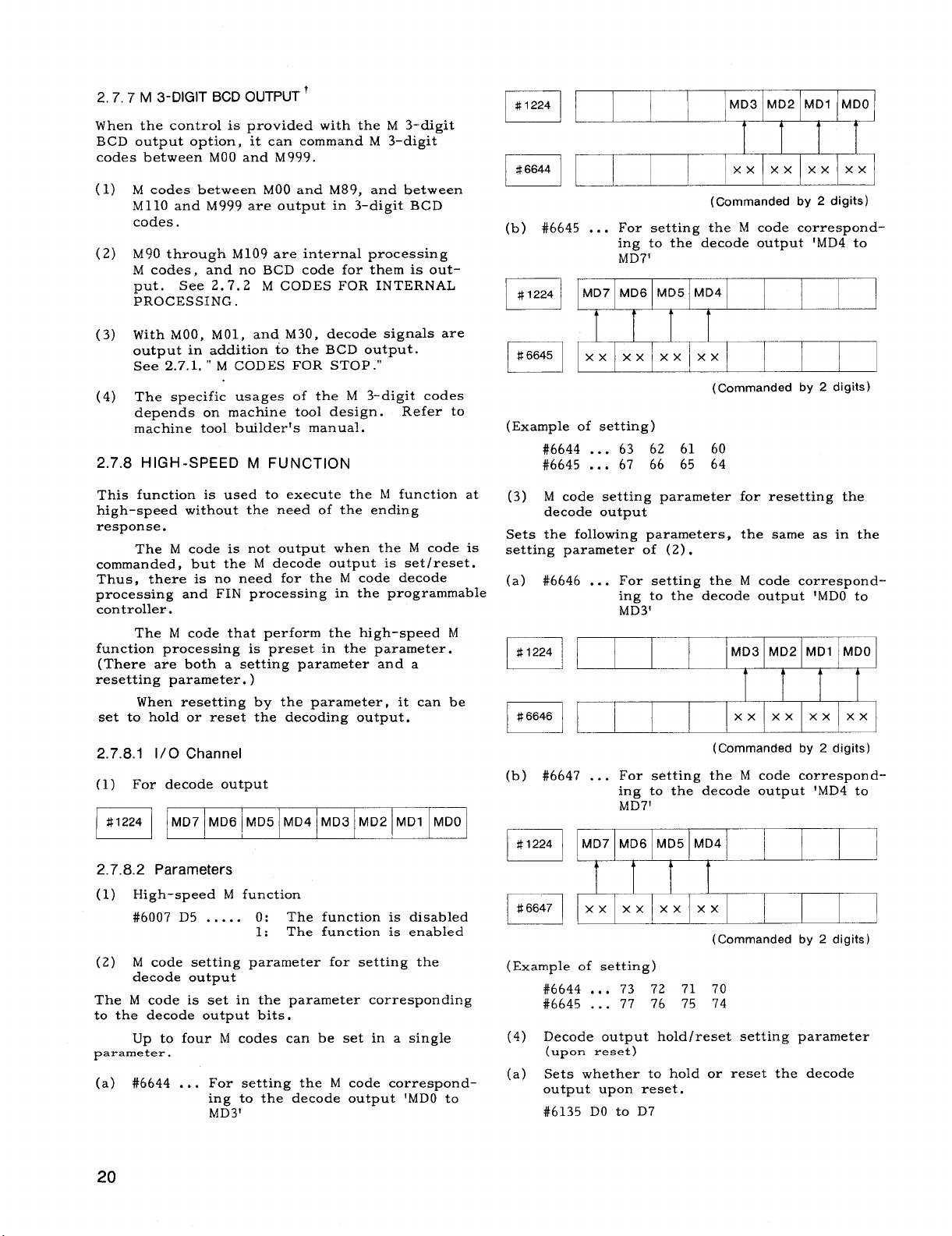
2.7.7 M 3-DIGIT BCD OUTPUT T
When the control is provided with the M 3-digit
BCD output option,it can command M 3–digit
codes between MOO and M999.
(1)
M codes between MOO and M89, and between
M11O and M999 are output in 3-digitBCD
codes.
(2)
M’W through M109 are internalprocessing
M codes, and no BCD code for them is out-
See 2.7.2 M CODES FOR INTERNAL
put,
PROCESSING .
(3)
With MOO, MO1, and M30, decode signalsare
output in additionto the BCD output.
See 2.7.1,“
(4)
The specificusages of the M 3-digitcodes
depends on machine tool design. Refer to
machine tool builder’smanual.
2.7.8 HIGH-SPEED M FUNCTION
M CODES FOR STOP. ”
# 1224 MD3 MD2 MD1 MDO
ml
I I
#
6644
I I
xx xx xx xx
ml
(Commanded by 2 digits)
#6645 . . .
(b)
1224
#
ml
#6645
ml
(Example of setting)
#6644
#6645 ...
For settingthe M code corresponding to the decode output ‘MD4 to
MD7’
MD7 MD6 MD5 MD4
I
I
i
xx xx xx’
X X
... 63 62 61 60
67 66 65 64
,
Commanded by 2 digits)
(
This function is used to execute the M functionat
high-speed without the need of the ending
response.
The M code is not output when the M code is
commanded, but the M decode output is set/reset.
Thus, there is no need for the M code decode
processing and FIN processing in the programmable
controller.
The M code that perform the high-speed M
functionprocessing is preset in the parameter.
(There are both a settingparameter and a
resettingparameter.)
When resettingby the parameter, it can be
set to hold or reset the decoding output.
2.7.8.11/0 Channel
(1) For decode output
#
1224
ml
2.7.8.2 Parameters
(1)
(2) M code settingparameter for settingthe
The M code is set in the parameter corresponding
to the decode output bits.
Parameter.
(a) #6644 ...
MD7 MD6 MD5 MD4 MD3 MD2 MD1 MDO
High-speed M function
#6007D5 ..... 0:
decode output
Up to four M codes can be set in a single
1
The functionis disabled
The functionis enabled
1:
For settingthe M code correspond-
ing to the decode output ‘MDO to
MD31
(3) M code settingparameter for resettingthe
decode output
Sets the followingparameters, the same as in the
settingparameter of (2).
(a) #6646 ...
# 1224
For settingthe M code correspond-ing to the-decode output ‘MDO-to
Mb3’
D
# 6646
n
(b) #6647 . . .
(Example of setting)
#6644 ...
#6645
(4) Decode output hold/resetsettingparameter
(upon reset)
(a) Sets whether to hold or reset the decode
output upon reset.
#6135 DO to D7
For settingthe M code correspond-ing to the–decode output ‘MD4 to
MD7’
MD7 MD6 MD5 MD4
i I I
xx~xx
lxx
73 72 71 70
... 77 76 75 74
Xxlxxlxxlxxl
(Commanded by 2 digits)
t
xx
(Commanded by2 digits)
t
1
20
Page 29
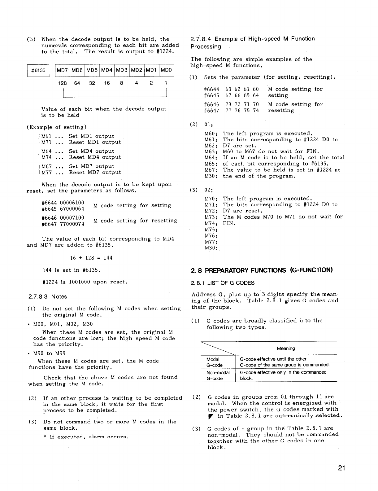
(b) When the decode output is to be held, the
numerals corresponding to each bit are added
to the total.
#61
35 MD7 MD6 MD5 MD4 MD3 MD2 MD1
E~
(Examp]e of setting)
reset,
and
I
128 64 32 16 8 4 2 1
Value of each bit when the decode output
is to be held
M61 .,.
{
M71 ...
M64 ...
{
M74 ...
jM67 ,..
lM77 ...
When the decode output is to be kept upon
set the parameters as follows.
#6644 00006100
#6645 67000064
#6646 00007100
#6647 77000074
The value of each bit corresponding to MD4
MD7 are added to #6135.
The resultis output to #1224,
MDO
Set MD1 output
Reset MD1 output
Set MD4 output
Reset MD4 output
Set MD7 output
Reset MD7 output
M code settingfor setting
M code settingfor resetting
16 + 128 = 144
2.7.8.4 Example of High-speed M Function
Processing
The followingare simpleexamples of the
high-speed M functions.
(1) Sets the parameter (for setting,resetting).
#6644
#6645
#6646
#6647
(2) 01;
M60;
M61;
M62 ;
M63;
M64;
M65;
M67;
M30;
(3) 02;
M70;
M71;
M72;
M73;
M74;
M75;
M76;
M77;
M30;
63 62 61 60
67 66 65 64
73 72 71 70
77 76 75 74
The leftprogram is executed.
The bitscorresponding to #1224 DO to
D7 are set.
M60 to M67 do not wait for FIN.
If an M code is to be held, set the total
of each bit corresponding to #6135.
The value to be held is set in #1224 at
the end of the program.
The leftprogram is executed.
The bits corresponding to #1224 DO to
D7 are reset.
The M codes M70 to M71 do not wait for
FIN .
‘M code settingfor
setting
M code settingfor
resetting
144 is set in #6135.
#1224 is 1001000 upon reset.
2.7.8.3Notes
(1) Do not set the following
the originalM code.
. MOO, MO1, M02, M30
When these M codes are set, the originalM
code functionsare lost;the high-speed M code
has the priority.
● M90 to M99
When these M codes are set, the M code
functionshave the priority.
Check that the above M codes are not found
when settingthe M code.
(2) If an other process is waiting to be completed
in the same block, itwaits for the first
process to be completed.
(3) Do not command two or more M codes in the
same block.
* If executed, alarm occurs.
h! codes when setting
2.8 PREPARATORYFUNCTIONS (G-FUNCTION)
2.8.1 LISTOFG CODES
Address G, plus up to 3 digitsspecifythe meaning of the block. Table 2.8.1 gives G codes and
theirgroups.
(1) G codes are broadly classifiedintothe
followingtwo types.
Meaning
Modal
G-code
Non-modal
G-code
(2)
G codes in groups from 01 through 11 are
modal.
the power switch,
~ in Table 2.8.1 are automaticallyselected.
G codes of * group in the Table 2.8.1 are
(3)
non-modal.
together with the other G codes in one
block .
G-code effective until the other
G-code of the same group is commanded.
G-code effective only
block.
When the controlis energized with
the G codes marked with
They should not be commanded
inthe commanded
21
Page 30
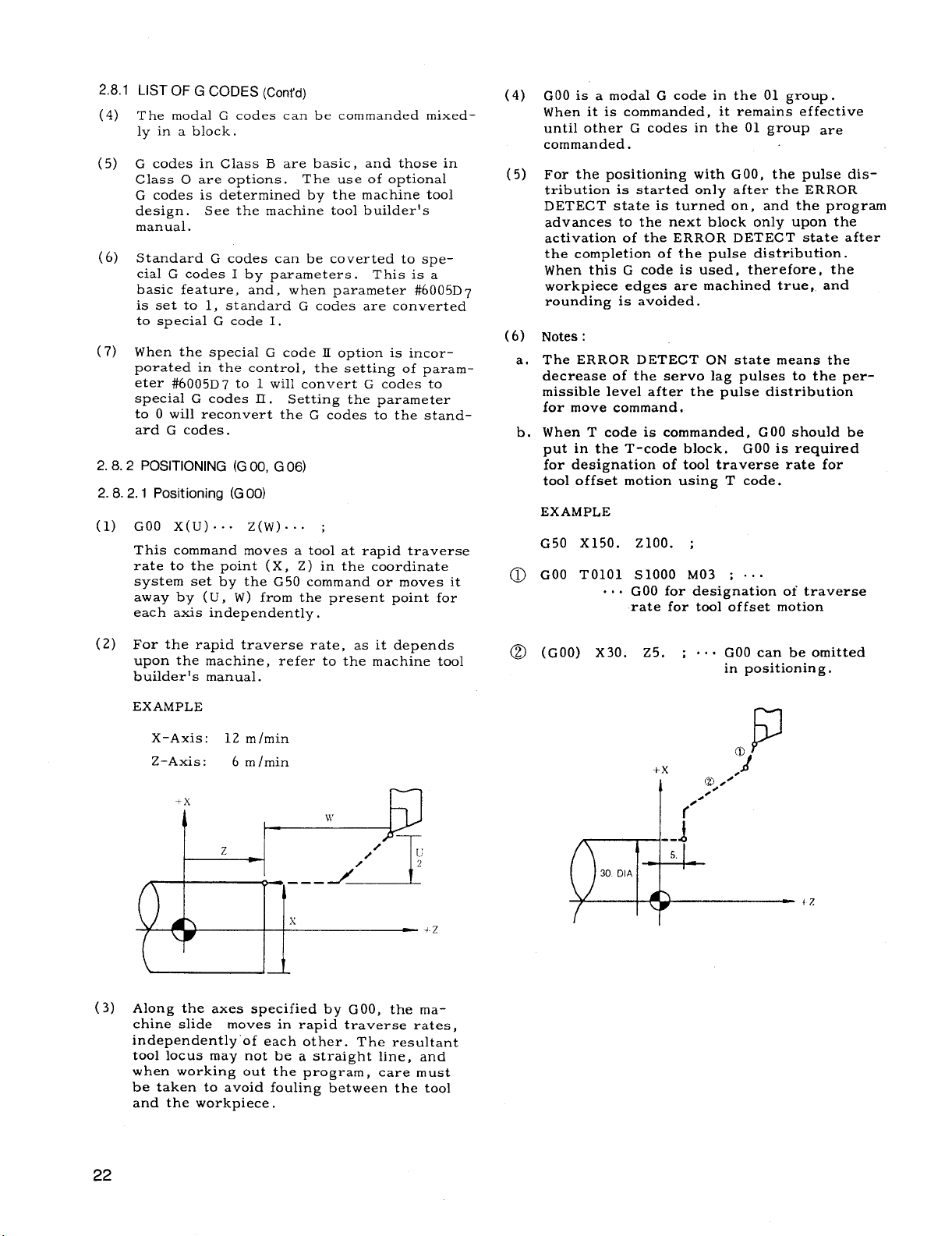
2,8.1
LIST OF G CODES (Cent’d)
(4)
The modal G codes can be commanded mixedly in a block.
G codes in Class B are basic, and those in
(5)
Class O are options. The use of optional
G codes is determined by the machine tool
design.
manual.
(6)
Standard G codes can be coverted to spe-
cialG codes I by parameters.
basic feature,
is set to 1, standard G codes are converted
to specialG code I.
(7)
When the specialG code IIoption is incor–
porated in the control,the settingof parameter #6005D7 to 1 willconvert G codes to
specialG codes II.
to O willreconvert the G codes to the standard G codes.
POSITIONING (G 00, G 06)
2.8.2
2.8.2.1 Positioning (G00)
GOO X( U)... Z(W) ... ;
(1)
This command moves a toolat rapid traverse
rate to the point (X, Z) in the coordinate
system set by the G50 command or moves it
away by (U, W ) from the present point for
each axis independently.
See the machine toolbuilder’s
This is a
and, when parameter #6005D7
Settingthe parameter
(4)
GOO is a modal G code in the 01 group.
When itis commanded, itremains effective
untilother G codes in the 01 group are
commanded.
(5)
For the positioningwith GOO, the pulse dis-
tributionis startedonly after the ERROR
DETECT stateis turned on, and the program
advances to the next block only upon the
activationof the ERROR DETECT stateafter
the completionof the pulse distribution.
When thisG code is used, therefore,the
workpiece edges are machined true, and
rounding is avoided.
Notes:
(6)
The ERROR DETECT ON statemeans the
a.
decrease of the servo lag pulses to the permissiblelevelafterthe pulse distribution
for move command,
When T code is commanded, GOO should be
b.
put in the T-code block. COO is required
for designation of tooltraverse rate for
tooloffsetmotion using T code.
EXAMPLE
G50 X150. z1OO. ;
cOO TO1O1 S1OOO M03 ; .0.
o
... GOO for designationof traverse
rate for tooloffsetmotion
(2)
For the rapid traverse rate, as itdepends
upon the machine, refer to the machine tool
builder’smanual.
EXAMPLE
X-Axis:
Z-Axis:
\
Along the axes specifiedby GOO, the ma-
(3)
chine slide moves in rapid traverse rates,
independently”ofeach other. The resultant
toollocus may not be a straightline,and
when working out the program, care
be taken to avoid foulingbetween the tool
and the workpiece.
12 m/min
6 mlmin
It
—
must
(GOO) X30. 25. ;
@
... GOO can be omitted
in positioning.
P
+x
I
f
?4
cl),.~”
/’”
22
Page 31

Table 2.8 List of G Codes
B: Basic
O: Optional
G Code
r
G 00
‘=a —
-* ,!!!ifn::fli’’oning
G20 1 G 20 G 70 I Inch input specification
G21 G21 G71
G 22
G 23 G 23 G 23
G27
G 28 G 28
G 29
G30 G30 G30
G31 G31 G31 Skip function
—
G 32 G33 G33
G34 G34 G34 Variable lead threadcutting
G35
G36 G38 I G%
G 37 G37 G 37 Stored stroke limit 2nd area OFF
G39 G 39
r
G40
G41 G41 ~ G41 !
G42 G 42
G43 I G43
: -1
G44
Special Special ~
G Code I G Code II ! Group
7
GIXI
G 22
G 27 G27
G 29 G29
G35
I
r
+
r
Go” Positioning (rapid traverse feed) B
~
G 22 Radius programmingfor circular interpolationCW o
;2~
G351* ~ Tool set error compensation
I
G38 G36 ~
G 39
G40
G44 G44 ,
r
G 40
G42 1 C6
G43 Tool radius compensation No, 3
I
-–T
Function Section
Linear interpolation, angle programmingfor linear interpolation
Circular interpolation CW, (radius R designation)
Circular interpolation CCW, (radius R designation)
05
Metric input specification
“l
Radius Programmingfor circular interpolation CCW
Reference point return check
I
I Automatic return to reference point
*
Return from reference point
Retunrn to 2nd reference point
Threadcutting, continuous threadcutting, multi-start threadcutting
01
I Stored stroke limit 2nd area ON
07
Stored stroke limit 3rd area ON
06
Stored stroke limit 3rd area OFF
! Tool radius compensation cancel o
Tool radius com~nsation No. 1
Tool radius compensation No. 2
I Tool radius compensation No. 4 0
+
B, O
B, O
~ B,O
‘!
o
o
o
B
B
B
o
o
] ’00
I
o
10
o
0
o–
0
~ shows the G codes selectedwhen the control
ispowered or reset.
Notes:
1. The followingG codes for initialstatewhen
power isappliedcan be setby parameters.
I
I
Parameter
$6005 De
$6005 DI
46005 Do
Group
01
G code
GOOor GOl
04 I G980r G99
03 I G900r G91
2.
When the controlisreset,whether G code
of 01 group should be GOO or kept as the
currentone can be setby parameter#6005D6.
3,
Radius programming forcircularinterpolation
can be made by G02 and G03 insteadof G22
G23, respectively.
4.
Corneringcan be programmed by GO1 instead
of Gll and G12.
5.
Initialstatesof G codes of 05, 07, 08 groups
when power isapplied
Refer to 2.8.7 Cornering.
are determinedby
theirrespectivesettingdata (#6001Do, D] ,
D2).
Page 32

2.8.2.1 Positioning (GOO)(Cont’d)
B: Basic
Table 2.8 List of GCodes (Cent’d) O: Optional
~ ~de I Special
G 50 G92 G92
G51 G51 G51 Return of current display value to origin o
G65 G65 G65
G66 G66 G66
7
G 67 G67 G 67
G6B G66 G6B
r
G 69 G69 G 69
G70 I G70 I G72 I
G71 I G71 I G 73 I
G72 I G72
G75 I G75 I G77 I
G76 I G76
G90 I G77 I G20 I I Turningcycle A
G 92 G78 G21 01
G94 G 79 G 24 Facing cycle B
G96 ~ G96
r
G 97 G 97 G 97
r
G96
r
G99
G 122 G 122 G122 Tool registration start
r
G 123 G123 G 123 Tool registrationend
Gill G 111 G 111 Taper multiple baveling/rounding o
G112 G112 G112
GCode I GCcde
r
v
F r
I
G94 G94
G 95
,
G80 G90
G91 G91 Incremental ccmmand B
F
Special 1
r
r
G 74
I
G 78
I
G=
I
G 95
r
r
Group Function
II
Coordinatesystemsetup
*
1 Meximumspindlerevolutionsetup,workcoordinatesystemsetup o
*
User macro simple call
User macro modal call
09
User macro modal call cancel o
1
Mimer image by programmingON o
10
Mirrof image by programmingOFF o
I Finishingcycle
I Stock removal in turning
I
I
I
I I I
I Stock removal in facing
* = ‘U’’ip’ere
I Automatic threadcutting cycle I
I
Threading cycle
Constant surface speed control
02
Constant surface speed control cancel
Feed cer minute (mm/min)
04
Feed per revolution (mm/rev)
Absolute command
03
11 Tool life control
I
I
I
*
Arc multiple beveling/rounding
Section
B
o
o
10
10
o
0
0
0
0
B
E
B
B
o
o
[B
I
B
B
o
o
+
o
~ shows the G codes selectedwhen the control
ispowered or reset.
Notes:
1. The followingG codes forinitialstatewhen
power isappliedcan be setby parameters.
Group ]
01 GOOor GOl
04
03
I
G code
G980r G99
G900r G91
I
I
Parameter
#6005Di5
DI
#6005
#6005 Do
2.
When the controlisreset,whether G code
of 01 group shouldbe GOO or kept as the
currentone can be setby parameter#fIO05D6.
3,
Radius programming for circularinterpolation
can be made by G02 and G03 insteadof G22
G23, respectively.
4. Corneringcan be programmed by GO1 instead
of Gll and G12.
Initialstatesof G codesof 05, 07, 08 groups
5.
when power is appliedare determinedby
theirrespectivesettingdata (#6001DcI, D1 ,
D2).
Refer to 2.8.7Cornering.
Page 33

2.8.2.2 Error Detect off Positioning (G06)
G06 x(u)””” z(w)””” ;
(1)
With thiscommand the positioningprocess
isidenticalto that of GOO except for the
followingaspects.
G06 is a non-modal G code in the * group.
a.
Itis effectiveonly in the programmed block.
EXAMPLE
GOO X.. . Z.. . ;
G06 x.. . z.. . ; —
x.. . z.. . ; — Move by GOO
With the positioningof G06, the positioning
b.
mdse distributionis immediatelystarted
L ,
on the completionof the pulse distribution
Move by
for the preceding block, aftermaking an
ERROR DETECT check, and the program
advances to the next block afterthe completion of the pulse distributionprocess. For
thisreason, wrokpiece edges are rounded
to the extent of servo lag pulses.
G06
EXAMPLE
G50 X1OO. z60. ;
GOO T0202 s600 M03 ;
x35. Z5. ;
Executed by
“~---- lineari.ter-
(2)1
L
x60. FO.2 ;
I
I
polationGO1.
Note:
The ERROR DETECT ON /OFF signals
(SMZ) are effectiveonly for cutting feeds, and -
have no influenceon the motion under COO and
G06.
LINEAR INTERPOLATION (G01)+
2.8.3
GO1 X( U)... Z(W)” O” F(E).”. ;
A toolis moved to the point (X, Z) on a straight
lineat the traverse rate designated by the F or E
code in the coordinatesystem set by G50
moved away by (U, W ) from the present point.
F or E code must be s~ecifiedin the block containingthe GO1 or in {he previous block. If
not, itcauses a format error. Feedrate desig-
nated by the F or E code is the tangentialfeedrate.
+x
z
x
POSITION PROGRAMMED
w
/
I
u
2
PRESENT TOOL POSITION
+Z
(
I
Angle programming for linearinterpolation
With the controlequipped with thisoption,
linearinterpolationcan be commanded at
specifiedangles.
GO1 X(U) O”” A“”. F(E)”sc ; (a)
or
GO1 Z(W).”” A“. . F(E) .0” ;
(b)
With these commands, a linearinterpolation
willbe executed by specifyingangle A in
the + directionof the Z-axis and distance
eitherin X- or Z-axis direction. The feedrate in the tangentialdirectionis specified
by the F or E code. The range of angle
specifiablewith address A is as follows.
Programmable Range of Angle A
Metric Input
Inch input
+
I
O– *360.000°
25
Page 34
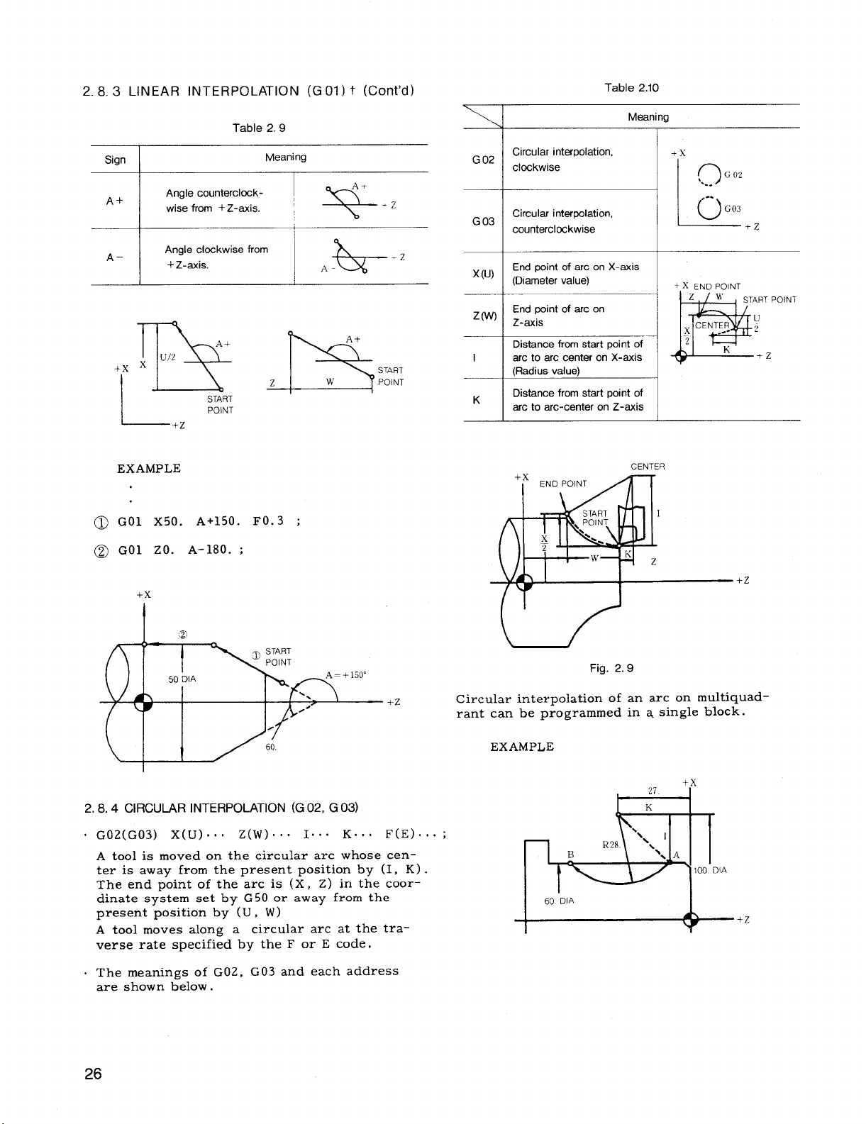
2.8, 3 LINEAR INTERPOLATION (GO1) t (Cent’d)
Table 2.10
Sign
A+
A–
+x
lx
I
EXAMPLE
GO1 X50. A+150.
GO1 ZO. A-180. ;
Angle counterclock- ,
wise from + Z-axis. !
Angle clcckwise from
+ Z-axis.
u/2
!rR
START
POINT
Table 2.9
A+
Meaning
A.
‘%
A-
&
A+
z
-P3
FO.3 ;
w
.Z
START
POINT
Meaning
Circular interpolation,
G 02
clockwise
Circular interpolation,
G 03
counterclockwise
-z
——
End point of arc on X-axis
x(u)
(Diameter value)
End point of arc on
z (w)
Z-axis
Distance fromstart point of
arc to arc center on X-axis
I
(Radius value)
Distance fromstart point of
K
arc to arc-center on Z-axis
+x
END POINT
#
q
x
o
CENTER
+x
L
+~ END POINT
Zw
CENTER
~ --- 2
2
@
I
9
‘.. -
0
..
G 02
G03
START POINT
K
-rZ
u
+Z
+x
I .2
+Z
2.8.4 CIRCULAR INTERPOLATION (G 02, G 03)
. G02(G03) X( U).., Z(W) ... I’.” K“” F(E) ”.;
A toolis moved on the circulararc whose center is away from the present positionby (I, K) .
The end point of the arc is (X, Z) in the coor-
dinate system set by G50 or away from the
present positionby (U, W)
A toolmoves along a circulararc at the tra-
verse rate specifiedby the F or E code.
. The meanings of G02, G03 and each address
are shown below.
+2
Fig. 2.9
Circular interpolationof an arc on multiquadrant can be programmed in a singleblock.
EXAMPLE
+x
B
DIA
60
+Z
Page 35

Table 2.11
K
The above case can be programmed as follows.
GO1 Z-. . F.. . ;
G02 x60.
s The feedratecommanded by the F code is a
tangentialfeedrate.
Notes:
The directionof the arc of G02 for Clockwise
1.
is defined as follows.
“When viewing the X, Z plane in -Y direction
in the right-hand coordinatesystem, the tool
moves clockwisefrom the beginning point of
the arc.“
Therefore, the directionof rotationin the
plate (-X~Z plane) in the figurebelow is
presented inversely.
- fizz . Jz–&-
= –19.596+ –19.60mm
z-46.6 120. K-19.6 F.. . ;
-x
G02
/
o
-.
Note that ifthe end point is designated in the
shaded area, the alarm is not displayed and the
toolwillcontinue to move endlessly.
The end point coordinateshould be precisely
commanded when the circularinterpolationis
appliedto the toolnose radius compensation, or
the tool may not move properly. Generally,it
is recommendable to calculateup to the next
digitof leastinput increment and count frac-
tionsover 1/2 as one and disregard the rest.
3.
When the controlis provided with Radius
Programming for CircularInterpolation,ra-
dius value can be commanded by G02, GC13
insteadof G22, G23.
EXAMPLE
G03 X80.O Z1500 I-10.O K-3000 F150 ;
a.
x
END
I
POINT
40.00
20.00
B
G03 U40.O W-40. O 1-10.0 K-30.O F150 ;
b.
x
1,
40.00
G03
CENTER___
– 30.00
1500 55.00
END
POINT
–40.00
START
POINT
– 10.00
I
z
L-.____+z
2.
When the end point of arc is not designated
on the circumference specifiedby the radius,
the alarm is not displayed and the toolpath
is as follows.
point of arc,
/
~
The mark o indicatesthe end
?
0---
ARC
CEt4TER
o--
-0
/
~
20.00
I
1500
5 DWELL (G04)
2.8
(1)
G04 U(P) . .. ;
This command interruptsfeed for the length
of time designated by the address U or P.
(2)
Dwell is programmed as an independent
block.
The maximum length of time which can be
(3)
designated with address U or P is as follows.
Dwell time: I O.001 to 9999.99 seconds
Dwell time is not influencedby input/output
increment.
I
5>00
z
27
Page 36

2, 8.5 DWELL (G 04) (Cent’d)
EXAMPLE :
G04 U3.5 ...
G04 P3500 o“o
3.5-second dwell
3.5-second dwell
The offsetvalues for which no
programmed are not changed.
EXAMPLE
G1O P16 X32.5 wO.05 ;
address is
Notes:
1.
GOLIis
2. The counting of dwell time is started from
the instantthe controlenters the ERROR
DETECT ON state upon completionof the
move command block before G04.
Therefore, with G04 UO ;, the control
advances to the next block immediately
after detecting the ERROR DETECT ON
state.
EXAMPLE
GO1 W-1. F25 ;
G04 UO.2 ;
GO1 W-1, ;
With the above program, chip cutting feed
is obtained.
a non-modal G code.
— 1 mm feed
— O.2 second dwell time
— 1 mm feed
+x
I 02DWELL
1mm
i-l
—.—
0.05 mm is added to
_r
Z-axis value
p-
Contents of tooloffsetNo. 16
is changed
(2)
The above format is used to make offset
tapes,
value
OffsetM-emery at once.
The tape format is as follows.
/
Label
%;
GIO P... X.. . Z.. . R.. . ;
I
X-axis value is set to 32.5 m
and to store the values in
—————
—
I GIO P... X... Z... R... ;
I
I G1OP,., X... Z... R... ;
2.8.7 CORNERING (G11,G 12)t
(1) Beveling (Gil)
2.8.6 TOOL OFFSET VALUE (G 10)+
With G 10 command,
set and corrected.
(1) G1O P-.. X(U)””- Z(W)” C” R“”. ;
With this command, tool offsetvalues are
set or corrected in part programs.
P For specifying tool offset No.
x Forchanging the tool offset value to the
specified value.
z
For adding the specified value to the original
u
w tool offset values.
I Forchanging the tool radius to the specified
n
,.
value.
tooloffsetvalues can be
Meaning
Gll
This command removes the sharp corner of
workpiece. Addresses X and Z cannot be
specifiedsimultaneouslyin a block.
Meaning of each address is shown below.
X(U)... K.. .
Z(W) ... I...
{
F(E) ... ;
}
28
Page 37

Beveling for X-axis
Beveling for Z-axis
Gll X(U),.. K... F(E),.. ;
K– K+
END POIN1
\
+x
45”
I
7?!7
STAfi POINT
.U
2X
(DIAME
TER)
K i
L
Bevellng Value
L
Bevellng O[rectfon
Beveling values (K and I) are limitedwithin
the followingvalues.
Gll Z(W)... 1... F(E)... ;
END POINT
1+
I–
h
L
45”
/
1
w
T-
L
(2) Rounding (G12)
Bevellng Dlrecton
START POINT
I
Bevellng Value
(Rad!us Value)
lKl<lU/21
> III<IWI
The command exceeding the above value causes
format error.
GOO X30. 20 ;
:=
Fig. 2.10
This command performs the rounding
corner.
Addresses X and Z cannot be spec-
of the
ifiedsimultaneouslyin a block. The corner
is formed as a quarter-round.
Meaning of
each address is shown below.
29
Page 38

2. 8.7
CORNERING (Gil, G12)
t (Cent’d)
Table 2.14
Roundingfor X axis
G12 X(U),,, K... F(E),.. ;
K
K*
:~p,
?Z
K ~ ~~~
r
STARTPOINT
Roundingvalue
Rouqd[ngd{recllon
;&T
‘L
Rounding values (K and I) are limitedwithin Notes:
the follo~ingvalues.
1.
G 11 and G 12 are modal G codes in the A group.
They remain effectiveuntilother G codes in
\Kl<l U/21 , III<IwI
The command exceeding the above value
causes format error.
COO X20. ZO ;
the group A are commanded.
2.
G 11 and G 12 are for one axis only. Ifthey
are commanded for both axes in the same
block, they constitutea format error.
EXAMPLE
G12 X.. . W.. . K.. . ;
Roundingfor Z axis
G12 Z(W)... K.,. F(E).., ;
L
Round!ngvalue
Roundingdlrecllon
Error “050”
In the G 10 or G 12 modes, no block without
3.
~
I and K nor block in which I and K are O
can be commanded.
If such a block is com–
manded, correcttool movement can not be
assured.
6.
+x
25.
Tool radius compensation functionfis effec-
4.
tiveto the blocks containingG 11 or G 12.
/
I ‘-
70 DIA
9
~.
2,
20 D14
..\
1,
I
+2
In the finishform commands G70 through G73
5.
of the specialcanned cycle t,blocks contain–
ing Gll or G12 can be commanded.
GO1 code can be used instead of G 11 to speci-
6.
fy identicalbeveling.
GO1
X( U)... K.. .
z(w) ... 1’..
I
7.
GO1 code can be used insteadof G12 to speci-
fy rounding.
However, in thiscase, R must
1
F(E), .. :
J
be used instead of I and K.
Gol jX(U) ... R.. .
Z(W) ... R.. .
\
F(E) ... ;
1
Page 39

2.8.8 lNCH/METRIC DESIGNATION BY G CODE
(G20, G 21)’
Unit of measurement (metricor inch) of input
data is selectivelyspecifiedby the followingG
codes.
G code I Input Unit
G*O \ Inch input
(321 I Metricinput
4.
The tooloffsetvalues are processed differently in the G20 mode and the G21 mode.
G 20/G21 must be commanded aftermodifying
the tooloffsetvalues.
Stored
Offset
Values
15000 1.5000 in. 15.000mm
2.8.9 RADIUS PROGRAMMING FOR CIRCULAR iNTERPOLATION (G 22,
Processing in G 20 Processing in G 21
(Inch) (Metric)
G 23)+
These G codes are programmed at the leading
end of a block of itsown.
are commanded, the unitsof allthe following
motions are changed.
Subsequent part programs
a.
Tooloffsetvalues
b.
Part of settingsand parameters
c.
Part of manual movements
d.
Displays
e.
Notes:
1, When G20 or G21 is commanded, the setting
of inch/metric selectionis changed. There–
fore,the stateof G2CI/G 21 at the time of
power applicationdepends on the setting
by parameter #6001Do.
EXAMPLE
ER
CR
01234 ;
G20 ;
n
I
I
Ifthese G codes
Inch input designation
L---d
When G 20/G21 selectionis commanded in the
2,
program, take the followingprocedure beforehand.
Cancel work coordinatesystem (G50T ), if
a.
used.
b.Cancel toolpositionoffset,and toolradius
compensation (G41 - G44) .
In programming circularinterpolation(G 02, G03) ,
the control requires the data of the arc-center
coordinates.
the addresses I and K.
(1) In programming of G22 or G23, the control
automaticallycalculatesthe arc center coor-
dinates (I,K) from the radius value designated by the address R and performs circular
interpolation.
G22
(G23)
A toolmoves along the circulararc whose
center is radius R away from the present
position.
dinates (X, Z) set by G 50 or is away from
the present positionby (U, W) . Tool moves
along the circulararc at feedratedesignated
by F code.
(2) The meanings of G22, G23 and each address
are shown below.
(3) Designation of radius value R
Radius value R is commanded by incremental
value with a sign of radius programming.
In this case,
When radius value R > 0, an arc, describing
lessthan 180°, and when R < 0, an arc
describing more than 180° are specified.
G 23
Normally, they are given by using
X( U)... Z(W) . .. R.. . F(E) ... ;
)
The end point of arc is at coor-
Table 2.15
Meaning
Circular interpolationby radius for
CVV
Circular interpolationby radiusfor
Ccw
+.x
o=
c)’”
!_
+2
Take the followingprocedure afterthe com-
3.
mand of G20/G21 selection.
a.Program absolute zero point for allaxes
before move command (G50).
b.In principle,
tionwhen current positiondisplay (exter–
nal) is used.
make the display reset opera-
The X-coordinate of the end of the
x(u)
arc (Diameter value)
The Z-coordinate of the end of the
(w)
z
arc
Distance from the start point of an
R
to arc center
(Incremental value with sign)
t .x END POINT
w
g
I x“ R J
m’
POINT
+-----+2
31
Page 40

2.8, 9 RADIUS PROGRAMMING FOR CIRCULAR
INTERPOLATION (G22, G23) t (Cent’d) )
—
END
.---,
– R“’,
START
POINT
e-
\
G
--+R
G 02
W
POINT
?8LY OR
1
02 , BELOW
L
ii
~- --
Fig. 2.11
Therefore,
ter does not exist which causes data error
(alarms “031,” “034”).
~ < (Distancebetween startpointand end point)
Tool nose radius compensation is effective
4.
for the block containingG22 or G23.
5.
The block containing G22 or 23 can be
designated in finishingshape commands of
specialcanned cycles (G70 to G73) .
6.
When the controlis provided with radius pro-
gramming option, circularinterpolationby
radius (R) programming can be made by G02,
G03 instead of G22, G23.
in the followingcase, the arc cen-
2
tz
\
EXAMPLE
GO1 X40. Z-10. F20 ;
G02 (X40. ) z-52.5 R30. (F20) ;
(D
Notes:
1. G22 and G23 codes are modal. They are kept
untilother G code of 01 group iscommanded.
2. In the G22 or G23 mode, the block in which
R is not contained or R is designated as zero
should not be commanded. Radius cannot be
designated by I and K.
3.
When R is varied with both startand end
points fixed, the toolwillmove along the
followingcirculararc.
4
END
POINT ,Z’
—-
ARC CENTER
&
/
END POINT
R. ,-.
R,
START POINT
CENTER
Fig. 2.12
I
+Z
—-
R,
32
2.8.10
(1) G27 X( U)... Z(W). O. ;
(2)
Notes:
2.
REFERENCE POINT CHECK (G 27)
With thiscommand, the toolis positionedto
the absolutecoordinatepoint (X, Z ) or incremental coordinatepoint (U, W ) by moving
along the two axes simultaneously,and then,
the positionis checked for conformance with
the reference point. For the axis for which
no command is given, positioningand check–
ing are not executed.
z
w
-—-—- >
m
START POINT
Ifthe positionisthe reference point, the
return–to–referencelamp lights. The posi-
tionis the reference point in allthe axial
directionsspecified,the automaticoperation
is continued further.
the reference point even along one axis,
thisconstitutesthe return–position-error,
and the automatic operationis interrupted.
(Cycle startlamp goes off.)
The referencepoint is an fixedpoint on the
1.
machine toolto which the tool can return by
the motion under the controlof the automatic
reference point return or G28 automatic reference point return function.
‘rAutomatic Reference PointReturn .t’
If G27 is commanded in the toolpositionoffset mode, the toolreturns to the position
displacedfrom the reference point by the
tooloffsetvalue. Positioningcannot be made
at the reference point.
G27, cancelthe tooloffsetmode.
/
Fig. 2.13
REFERENCE POINT
/
/u
/
2X
/
If the positionis not
See 6.2.1,
Before commanding
Page 41

EXAMPLE
a. Canceling tooloffsetin the block pre-
ceding G27.
Tt1000;
G27 U.. . W.. . ;
b. Canceling in the block containingG27.
G27 U.. . W.. . TDUOO ;
“EEDM:!:ER
SPEED REDUCTION LIMIT SW
APPROACH SPEED 1
REFERENCE
POINT
Fig. 2.15
3. The mirror image functionis effectivewith the
motion commanded by G27. To avoid the
return positionerror, command G 27 in the
G69 mode (opposite toolpost mirror image
off).
AUTOMATIC RETURN TO REFERENCE POINT
2.8.11
(G28)
(1)
G28 X( U)... Z(W) ... ;
With this command, the toolcan be brought
back to the reference point automatically
after passing through an interimpoint. In
other words, the toolpositionsto the commanded absolutecoordinateposition(X , Z)
or incrementalposition(U, W ) by moving
simultaneouslyalong the two axes, and then
automaticallyreturns to the reference point
by the reference point return function.
The specifiedpoint (X, Z) or (U, W) is
known as “INTERIM POSITIONING POINT ,“
or IIINTERIM POINT .“
R~~~~ENcE
INTERIM POSITIONING POINT
POINT
,,
Thereafter, the RETURN TO REFERENCE
POINT motion is in rapid traverse as under
the command of GOO.
RAPID TRAVERSE
I
Fig. 2.16
(4) However,
when low traverse speed is specifiedby parameter #6010D 5 set to 1, the
same law motion speed as in the 1sttime is
obtained.
Notes :
For parameter settingand other detailsof
1.
the low traverse speed return motion shown
in Fig. 2.8.11.2, refer to 5.2.1 Manual Return to Reference Point.
2,
The startingpoint for RETURN TO REFERENCE POINT motion must be in the area
shown in Fig. 2.8.11.4. Fig. 2.8.11.3 can
be started from any position.
Fig. 2.14
The tooldoes not move along the axis for
which instructionisomitted.
(2)
When the return to reference motion is com–
pleted, Reference Point Return lamp for the
returned axis lights.
When the toolreturns
to the reference point in both axes, the
automatic operation is resumed.
(3)
The seriesof RETURN TO REFERENCE
motions are as follows. With initialpower
application,the return motions to the
reference point are as shown below in the
low-speed mode as shown below.
RETURN
DIRECTION
A
Before writing G28 in the program, cancel
3.
AXIS
the toolpositionoffsetas shown below .
a. Canceling in the preceding block
TUUOO ;
G28 X.. . Z... ;
b. Canceling in the block containg G28
G28 X.. . Z.. . TO EIOO ;
4.
When G 28 is writtenwith the toolposition
offsetor tool radius compensation on, the
offsetor compensation is automaticallycan-
celled.
33
Page 42

2.& 12 RETURN FROM REFERENCE POINT (G 29)
(1) With this function, the toolis positionedto
a specifiedpoint via the interimpoint, after
ithas been once returned to the reference
zero point by the AUTOMATIC RETURN TO
REFERENCE ZERO COMMAND (G28) .
G28 X.. . Z... ;
Point A+B+C
(referencezero point)
Point B
G29 x.. . z.. . ;
Point C+B+D
Point D
C (REFERENCE ZERO POINT)
-o-
Fig. 2.17
(2) When G.29is used,
tance between points B and C is unnecessary
in programming, Especiallywhen incremen-
talinstructionsare used, this functionis
usefulto return the toolto the originalco-
ordinatesystem afterreturning to the
reference zero.
considerationon the dis-
Notes:
Commanding G29 without the execution of
1.
G28 afterturning on the controlconstitutes
an error
11059.II
2, In principle,canceltooloffsetbefore pro-
gramming G28 or G 29. If they are programmed while offsetis effective,the interim
point B willbe offset,and the toolwillpass
point B‘.
~
(REFERENCE ZERO POINT)
4-
f
1’
~
/“
~,
0--” /
d“
A’
/
-..
\
If
3. Commanding G29 in the TOOL RADIUS COM-
PENSATION mode (G40 - G44) or in CANNED
CYCLES (G70 - G76, G90, G92 and G94) constitutesan error.
EXAMPLE
N50 T0300 ;
N51 G28 u80. w20. ;
N52 T0400 ;
N53 G29 u-80. w40, ;
OFFSET DISTANCE
/
B (INTERIM pOINT)
(3) Motions C + B and B + D are made simul-
taneously along the two axes in rapid trav-
erse. However, the toolwillnot move in
the directionfor which instructionisomitted
(4) Where G28 is programmed severaltimes,
the point B created by the latestG28 instructioniseffectivefor the motion by G29.
EXAMPLE (absoluteinput)
Coordinates of interim point is equivalentto
these two blocks.
N20 G28 X1O. Z20, ;—-(1% :0.)
N25 G28 x30. ;— (30.
20.)
~
IGOO x-40. z-50. ; I
c (REFERENCE
ZERO POINT)
+
,/
/’
/
,
,/’
=~’fL
,.
‘/
\\
\
\\
\
\
\\
t .x
lD—
h-hi-+
2.8.132ND REFERENCEPOINT RETURN (G30)+
(1) G30 X( U),.. ~(w).. ;
With thiscommand, the toolfirstmoves to
an interimpositioningpoint (X, Z) or (U,
W ) in two axialdirectionssimultaneously,
and then, moves to the 2nd reference point.
The tool does not move along the axis for
which no coordinate positionis specified.
-z
34
Page 43

z
/
-Q-
/
2ND REFERENCE
POINT
2
a.b,When the next block is programmed in incre-
mental values:
The toolmoves incrementallyin accordance
with the next block from the point where
the interpolationis interrupted.
EXAMPLE
POINT
/
INTERIM
POINT
Fig. 2.18
(2) The 2nd reference point is specifiedin
advance in terms of the distance from the
1st reference point commanded by G28, by
parameters #6612 and #6613.
EXAMPLE
G30 U-40. W30 ;
r-~<--~~E:R
TO 2ND REFERENCE
POINT
PARAMETER 16613
Notes:
Before commanding G 30, afterthe energiza-
1.
tionof the control,G28 or MANUAL RETURN
TO REFERENCE POINT must be executed.
2. For the 2nd REFERENCE POINT RETURN
motion, there is no area from where returning is impossible,
and the toolcan be return
from any position.
The same notes 3, and 4. of (5) for 2.8.11
3.
Automatic Return to Reference Point apply
to G30 command.
4.
When G 29 is commanded afterG 30, the tool
moves via the interimpoint specifiedby G 30
to the positionspecifiedby G 29. However,
the interimpoint is renewed only in the axis
specifiedby G30.
2.8.14
(1)
SKIP FUNCTION (G 31)+
G31 x(u) ... z(w) ... (F(E) ...) ;
With this command, a speciallinearinterpolationis executed. During the interpolationmovement under thisinstruction,the
toolinterruptsthe interpolationmotion
immediately, and proceeds to the next block,
when a skip signal is received.
The motion after the receiptof a skip signal
(2)
varies with the instructionof the next
block.
POINT
,
G31 W120. ;
GO1 U1OO. ;
?
w’
50
I
I
L_._-z
ACTUAL
MOTION
d
/
SKIP
SIGNAL ON
COMMAND
When the next block is programmed in absolutevalues only for one-ax; s:
The toolmoves to the specifiedcoordinate
positionin the specifiedaxis. It remains
at the positionwhere the skip signalis re–
ceived, ifaxis is not specified.
EXAMPLE
G31 Z400. ;
GO1 X1OO. ;
I 0—)-.-+
l-----+ /=4
SKIP SIGNAL ON
c. When the next block is programmed in abso-
lutevalues along two axes :
The toolmoves to the commanded position
from the point at which a skip signalis
received.
EXAMPLE
G31 W1OO. ;
GO1 X300. Z200. ;
200.
I
\
I
---
‘\ 300 DIA
\
\
100.
x
Ll&7
z
SKIP SIGNAL ON
35
Page 44

2.8.
r!-71FE
14 SKIP FUNCTION (G31) t (Cent’d)
G31 is a
(3)
When no skip signalis received during the
executionof the block containingG31, the
toolstops at the end of the block, and alarm
“087” is displayed.
(4)
The feedratefor blocks containing G31 are
set in the followingtwo methods, selectively
specifiedby parameter #6019D4.
a.
Designationby F in the same way as with
normal programs.
Presettingof feedratesby parameter #6232.
b.
When a skip signalis received, the coordinate
(5)
values at that moment are automaticallystored
as parameter data.
These data can be used as system variables
in user macros.
Notes:
When parameter #6004D0 is set to 1, the pro-
1.
gram is advanced to the next block automati-
callyeven when no skip signal.is received
during the execution of the block of G31.
2,
Before programming G 31, be sure to program
G40 for canceling TOOL RADIUS COMPENSATION . Failureto do this initiates
alarm “024,“
3.
Commanding G 31 with skip signalON advances
the program to the next block without executing
the current block.
non-modal G code.
#6568 for storing X coordinatevalue
#6569 for storing Z coordinatevalue
Table 2.16
Format
Metric
Input
Metric
output
Inch
Input
Metric
Input
Inch
output
Inch
Input
F code is for normal thread cutting.
E code is for precise thread cutting.
(3) The directionof lead specifiedby F and E
codes is shown below.
Limitationof Taper Angle
‘Ly. I ::: I ‘-
F 32
E34
—
F 24
E26
F32 I FO.01–F1270.00 mm
E24 I EO.0003-E1270.00C0mm
Direction of Lead
Programmable Range
1
I
I
I
1
for Threadcutting
F0.01-F 500.00 mm
E0.0001 -E 500.0000 mm
F0,000I –F19.6850 in.
E0.000004-E 19.685000 in.
Direction of Lead
I
Lead in the direction of z-~is
Lead in the direction of X-axis
2.8.15
CUTTING (G32)
This functionis for cutting straightthreads,
taper threads, scrollsand for continuous thread-
ing.
(1) G32 X( U)... Z(W) ... F(E) ... ;
THREAD CUTTING, CONTINUOUS THREAD
With thiscommand, the toolcuts threads up
to the point (X, Z ) specifiedin absolute
coordinatesor (U, W) specifiedin incremental coordinatevalues, at a lead designated by F or E code.
(2) The range of leads to be specifiedby F and
E codes is as follows.
36
i~
p/2
)R-$===l+.+-J-+Z
<*, STARTPOIN,
Fig. 2.19
Feedrates are limitedby spindle-speed S as
follows.
The upper limitof X-axis speed component is
halfthe above.
Page 45
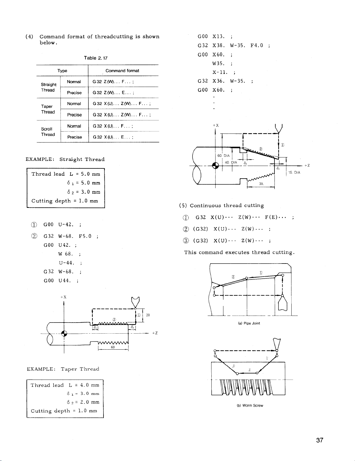
(4) Command format of threadcuttingis shown
below.
Table 2.17
Straight
Thread
Ty@
1 I
~~
Command format
GOO X13. ;
G32 x38. W-35. F4.O ;
GOO x60. ;
W35. ;
X-n. ;
G32 x36. w-35. ;
GOO x60. ;
“d F=+=++
EXAMPLE :
@ GOO u-42. ;
@ G32 w-68. F5.O ;
StraightThread
GOO U42. ;
w 68. ;
u-44. ;
G32 w-68. ;
GOO U44. ;
+x
I
I
(5) Continuous thread cutting
~ G32 X( U)O. O Z(W)”” O F(E),.. ;
@ (GE’)
@ (G32) X( U)... Z(w)... ;
This command executes thread cutting.
x(u).”. z(w).. :
I I
II
I
+Z
TX
EXAMPLE : Taper Thread
m
M
(a) Pipe Joint
T-1
—— -- ---- -—-
e
(b) Worm Screw
J
37
Page 46

2.8.15THREAD CUTTING, CONTINUOUS
THREAD CUTTING (G32) (Cent’d)
Since the stop time between thread cutting
blocks is approximately zero, smooth, continuous thread cuttingis possible. If
thread lead specificationischanged midway,
the thread becomes irregularnear the
boundary of blocks.
Notes:
Allowances 61 and 62 are required for thread
1.
cutting because lead error occurs near the
startingand end points.
Equation
~1 >~o~(ln~ –1)
L.S
[Y~>—
60. K
Table 2.18
L(mm):
S(r/min):
a (–):
Meanings
Lead of thread
Spindle speed
K:
Constant
(Normal value: 30)
Accuracy of thread
_AL. .. Lead emor
—
L
In:
Natural logarithm
(log e)
-x
-----—--
I
(G
{\
2.
If spindlespeed is not constant during thread
cutting,the leads become incorrectdue to the
servo lag.
3.
Threading up for thread is not effectiveat
G32.
commanded.
4.
The followingoperation’is disregarded during thread cuttingincludingG 32
, Feedrate Override o“o Regai-ded as 100%
. Feed Hold Operation
. Single Block Operation
5.
The G 32 command should not be commanded
in G98 mode,
In Dry Run mode, the toolmoves at Jog feed-
6.
rate.
Allowance forleaderror(61, 6 2)
(6)
+x
—
!
Ifnecessary, G92 (or G76t) should be
:
I
v
I
I
+Z
a 1150 1/100
(In ~ – 1) 2.91
EXAMPLE
Lead of thread L = 3.0 mm
Spindle speed
Thread cutting a = 1/100
‘(In+- 1)
6’> 60.K
_3. ox 500
—
60. K
62>=
60.K -
2.8.16
With this function, multi-startthreads containing
two or more threads per lead can be machined
without shiftingthe startingpoint.
cutting,the toolfeed is startedin phase with a
start point pulse (1 pulse/revolution)generated
by a pulse generator installedon the spindleto
controlthe startingpoint of thread always at the
same positionaround the workpiece circumference.
aftercutting a thread by controllingthe starting
point by the startingpoint pulse, another thread
is cut by startingthe cutting feed at an angular
positionof the spindlewhich is displacedfrom
the startingpulse positionby a preset angle.
MULTI -START THREAD CUTTING (G 32)+
With the multi-startthread cutting function,
1/150 1/200 1/250 1/300
3.61
4.01 4.29
S = 500r/rein
x 3.61 =3. Omm
_ 3.0X500 =083mm
60.K “
4.52 4.70
In thread
+“””
Fig.2.20
61 and 62 are obtained approximateely from the
followingequation.
Page 47

LEAD
n
Two-Starl Thread
Fig. 2.21
G32 X( U)... Z(W) ... F(E) ... B.. . ;
(1)
2. The angular positionfrom the startingpulse
can be specifiedin both forward and reverse
directionsby BO - B 360.commands.
When B command is made to specifyangles
3.
outsidethe permissiblerange (O - 360.000),
alarm IT0621!is displayed.
If multi-startthread cutting B is specified,continuous thread cutting cannot be
executed.
EXAMPLE
G32 W.. .
G32 W“””
B90
Continuous thread cutting cannot be performed
because of feedhold at
thisblock.
With this command, the toolcutsa thread
startingat an angular positionwhich is
displacedfrom the positioncorresponding
to the startingpulse by an angle specified
by B, to X(U) or Z(W) point, at a lead
specifiedby F or E code.
The data specifiedby address B in the
(2)
multi–startthread cutting functionis
as follows.
Least input increment: O.001 deg.
Programmable range: O S B S 360.000
When decimal point input is used, B 1.=ldeg.
The B code is non-modal, and is effective
only in the programmed block.
Number of startsand B code
(3)
In principle,the thread startingpointson
the-workpiece circumference
the circumference into equal
2-START THREAD
STARTING POINT
3-START THREAD
STARTING POINT
sh=uld divide
portions.
4-START THREAD
STARTING POINT
@@
EXAMPLE :
Two-start Thread
GOO U.. . ;
G32 WC. . F... ;
GOO U.. . ;
w.. . ;
u.. . ;
G32 W.. . ;
GOO U.. . ;
G32 W.. . B180.
GOO U.. . ;
w.. . ;
u“”” ;
G32 W.. . B180.
~ Threading of part @
I
;
I
@
1ST THREAD NO B 1 ST THREAD NO B
2ND THRkAD B180
COMMAND
2ND THREAD B120
3RD THREAD B 240
COMMAND
Fig. 2.22
1 ST THREAO NO B
2N0 THREAO B90
3 RD THREAO B 180
4 TH THREAD B270
COMMAND
Notes:
1. Since the angular positiondetectionpulses
(4096 pulsesJrev.) generated from the spin-
dle pulse generator is used to define the
angular positionof the spindle with respect
to the startingpoint as controlledby the B
command, the leastdetectableincrement is
360°/4096pulses “~0.08790/pulse,
From the positioncommanded by B codes,
an error up to 31 pulse may occur.
M\
Page 48

2.8.17VARIABLE LEAD THREAD CUTTING1
G74 X( U).., Z(W) ... K.. . F(E) ... ;
(1)
With thiscommand, variablelead screws are
controlledwith the increaseor decrease of
lead per revolutionspecifiedby address K .
VARIABLE LEAD SCREW
2.23 Variable Lead Threadcutting
Fig.
(3)
Confirmationcalculationfor K command of
variablelead thread cutting.
a.
K command is restrictedin the following
conditions.
(i)
Feedrate at end point must not exceed
programmable range.
500 mm/rev (metricoutput) or 50 in
rev (inch output)
Feedrate at end point must not be minus
(ii)
value.
(iii)
Accumulated value of movement due to
lead variationmust not exceed 4194.303
mm (metricoutput) or 419.4303in (inch
output).
(iv)
Feedrate change corresponding to lead
variationmust-not exce-ed5,400 mm /rein
(metricoutput) or 540 in/mm (inch output
The range of K programmable for variable
(2)
lead screws is as follows.
Least input increment:
0.0001 mm/rev.
0.000001
hdrev.
(MetricInput) (Inch Input)
Programmable range:
The highest feedrateis within the maximum
a.
programmable feedraterange (
500 mm/rev
(metric)or 50 in/r@v. (inch))
The totaldisplacementresulting from changes
b.
in lead is within the following.
4194.303mm (metricoutput)
419.4303in.
c.
Feedrate change corresponding to lead
(inch output)
variationmust not exceed 5,400 mm /rein
(metricoutput) or 540 irdmm (inch output).
Lead value should not be minus value.
d.
Notes:
1.
When variablelead threads arecut by continuous block programs, command pulses are
interrupted at block junctions.
If K commands exceed the permissiblerange,
2.
alarm I!06CI11willbe displayed.
3.
When G 34 command is executed in the Dry
Run mode, the tool moves only at the speed
specifiedby the manual continuous feedrate
command, ifparameter SGRDRN (#6019 BIT5)
is set to 1.
4.
When parameter
(!1oIN1((#6006D5) is set to
1, leastincrement for K commands is 0.001
mm/rev or O.0001 in./rev.
5.
Commanding address B in G34 block causes
alarm “060.“
b. The controlchecks the restrictiondescribed
above using the followingequation.
F:
Fixed lead command (mm/rev or ird
rev)
K:
Variable lead command (mm/rev or
in./rev)
Distance between startand end points
w:
on Z-axis (mm or inch).
For facing screw, distanceis specified
as U on X-axis.
Spindlenumber (rev/rein)
s:
Spindlenumber formovement betweenstart
N:
and end points(rev)
(i)
N=
Equation
F+:+
-(F +;) + (F +;)2 +20 K-W
for limitin a. (i)
KN 5 51)1).000”mm/rev or
/
K
50.0000in/rev
Equation
(ii)
(F+
Equation for limitin a. (iii)
(iii)
for limitin a. (ii)
$)2 +2 KW>0
Jj_KN2 ~ 41940303 mm or
419,4303in
Equation for limitin a. (iv)
(iv)
. K.N < 5,400 mm/min or 540 in/rein
&-
40
Page 49

2.8.18 STORED STROKE LIMIT (G 36-G 39)+
(3)
Setting 3rd prohibited area
This functionis for preventing the entry of the
toolintothe prohibitedarea,in both automatic
operation mode and manual operation mode, to
secure saferoperation. Three types of pro-
hibitedareas can be set up as shown below.
1ST PROHIBITED AREA
(BY PARAMETER)
OUTSIDE PROHIBITION
2ND PROHIBITED AREA
G36)
(BY
/ /
INSIDE OR
OUTSIDE
PROHIBITION
--l
D
INSIDE OR OUTSIDE PROHIBITION
E
+x
F
1
Fig. 2.25
(1)
Setting 1st prohibited area
Set + side boundary A and - side boundary
a.
P
I
3RDPROHIBITED
AREA (BY G 38)
B by parameter.
The area outside the
b.
range between points A
B is prohibited.
This area can not be
c.
specifiedby part
programs.
(2)
Setting 2nd prohibited area
Set + side boundary C and - side boundary
a.
D by the settingfunction.
Selectivelydesignatethe insideor the out-
b.
side of the area between points C and E by
parameter #6007D0.
=
In addition to the method by the setting
c.
function, the followinginstructioncan be
used to set a prohibitedarea, and to turn
on the area check functionalso.
a.
Set up + side boundary point E and - side
boundary point F by the settingfunction.
b.
Selectivelydesignate the insideor the outsideof the area between points E and F by
parameter #6007D1.
#6C07 DI
A
In additionto the method by the setting
c.
o
1
Meaning
Inside prohibition
Outside prohibition
function, the followinginst~uctioncan ye
used to set a prohibitedarea, and to turn
on the area check functionalso.
G38 U.. . W.. . 1... K.. . ;
-r--+
Point E
coordinate
Point F
coordinate
The area check functionis turned off by a
single code block G 39 ; .
Table 2.19 Parameters and Settings for
SettingProhibitedArea
axis Z axis Division
X
Ist
Prohibited Area
2nd
Prohibited Area
3rd
Prohibited Area
Point A
Point B #6606 I #6607
Point C
Point D ##6502
Point E
Point F
#6600
#6500
#6504
#6506
#6601
#6501
I/6s03
#6505
#6507 I
(4) Coordinate system for area setting
The above Points A through G are allset in
absolutevalues on the machine coordinate
system (MACHINE) . That is, the position
is written as the distance from the (lst)
reference point (1 = leastoutput (move) in–
crement) .
Therefore, this functionwillnot
become effectiveunless the manual or automatic RETURN TO REFERENCE ZERO is ex–
ecuted once afterthe energizationof the
control.
(5) Effective-ineffectiveselectionof prohibited
area
I
Parameter
Setthg
G36 U., . W.. . 1... K.. . ;
z-
coordinate coordinate
The area check functionis turned off by a
single code block G 37 ;.
With the followingsetting,the 2nd and the
3rd prohibitedareas are selectivelymade
effectiveand ineffective.
41
Page 50

2.8.18 STORED STROKE LIMIT (G36-G39) ~ (Cent’d) EXAMPLE
1ST PROHIBITED AREA
+x
A (2000, 1OCO))
3rd Prohibitedarea check OFF
~:=~
When G36 through G39 are commanded,
settingdata are automaticallyrewritten.
There~ore, the ON or OFF stateultimately
.
specifiedby G code commands or setting
functionbecomes effective.
The 1st prohibited area is always in the CHECK ON
mode.
(6)
Startingarea check
When the toolisreturned to the reference
point once manually or automaticallyafter
the energizationof the control,the area
check functionis startedimmediately.
Therefore, ifthe reference point is in the
prohibitedarea, immediately,STROKE
LIMIT ERROR willbe caused. In
thiscase, turn offthe area check function,
and change the data.
(7)
Stored stroke limiterror
When the tool enters the prohibitedarea,
itstops justinsidethe boundary line,and
the controlenters STORED STROKE LIMIT
ERROR state. In thiscase, the toolcan
only be moved manually in the return direc–
tion.
(8)
Displaying remaining distance
With thisfunction,the distance between the
current toolpositionand the boundary of the
prohibitedarea in the X and Z directions
are displayedon the CRT. Refer to 4.3.4.6.
“Stored Stroke Limit.“
these
2ND PROHIBITED AREA (NISIDE)
C (.5000, -8000)
—
2.8.19
(G40 THROUGH G44)
\
B = D(.11000,-10000)
Inside/Outside
Second Area
Third Area
First Area
TOOL NOSE RADIUS COMPENSATION
/
REFERENcE
/
POINT
/
3RD PROHIBITED AREA (INSIDE)
Table 2.20
Parameter/
Setting
I #6500
I #6501
I #6506 I -6600
\ #6506 I -7000
\ #6s07
I fl%oo
I
I
I
I
/
/
/
~<_. WORKPIECE
A.
Contents
– %00
– 6000
– 9000
2000
CENTER
I #6601 : 1O(.KI
#6606
I
I
–11OOQ
+Z
c
)
D
)
E
)
F
)
A
)
B
)
Notes:
1.
The pointson the boundary line in both
axes are included in the prohibited area.
2.
Two prohibitedareas can be set with partial
overlapping,
3. In the MACHINE LOCK ON mode, AREA
CHECK function is not effective.
Because of a nose radius of lathetools,there
is
a deviationbetween the desired curve and the
actualcurve produced.
Therefore, tool offsets
are not enough for taper and circularcuttings.
tool nose radius compensation option resolves
The
the problem of nose radius.
See Fig. 2.26.
Page 51

la
–-L \ \
TOOL NOSE
2.26
Fig.
Tool nose radius values
(1)
a.
Radius value storage
Tool nose radius value must be writtenin the
storage before the toolnose radius compen-
sationis commanded.
can be writtenin the storage depends upon
the machine.
T 3-digit:
T 4-digit: 16 or 50 sets
Refer to 2.6.2,“
9 sets
Tool Offset Memory+ .“
Number of patis that
CENTER
ER
(2)
T code designation
a.
The T code for toolnose radius compensation
must be programmed with sign (+ or –).
T f ❑ ❑ ❑ ❑ (In the case of T 4-digit)
T_l__T
~ Offsetnumber for toolposition
offsetand toolnose radius
compensation
~ Tool number
I
~ Directionof toolnose radius
compensation
11+!1 ,..
l!_ll . . .
+x
1
, -B a-
~+z
Right side viewed in the direction
of tooltravel
Left side viewed in the direction
of tooltravel
“T+“
Fig. 2.28
“T –“
Range of toolnose radius values
b.
Radius value can be set within the following
range.
R
&!
ALL ROUND
INSERT
Fig. 2.27
I
o k9.9999
VIRTUAL
TIP NOSE
R,
Metric Inch
o *99.999
Settingof toolnose radius values
c.
Radius value of toolnose must be set without signs.
G).
For the writingof radius values for tool
nose radius compensation, refer to Fig.
4.3.5 Displaying and Writing Tool Offset
Data,
R
‘---
The address character is R.
b.
When a toolis used for turning and for facing, as the directionof toolmotion changes,
the correct directionof compensation should
be programmed with sign of T code.
-x
&
The directionof compensation is changed
from + to - or - to + during program execution. G 40 or TO ❑ 00 command should not
be necessarilyprogrammed to cancel the
toolnose radius compensation.
(3)
G code designation (G40 to G44)
a.
G code of toolnose radius compensation
(G41 to G44)
One of G41, G42,
should be programmed before the execution
of toolnose radius compensation.
four G codes specify the relationshipbetween the virtualtoolnose and the tool
center.
RIGHT SIDE
COMPENSATION (T J- ‘
LEFT SIE)F
COMPENSATION (T –)
+2
Fig. 2.29
G43 and G44 and T code
These
43
Page 52

2.8.19 TOOL NOSE RADIUS COMPENSATION
THROUGH G 44) (Cent’d)
(G 40
G41
G42 \
I
.x
L
Fig. 2.30
Regardless of the mode of toolnose radius
compensation, the current positionof the
virtualtoolnose is displayed by depressing the POS pushbutton.
b. Issue G40 to cancel the toolnose radius com-
pensation.
c. Cautions in programming G code
(i) Since G40 to G44 are modal G codes of
06 group, they are retained untilthe
other G code is commanded. Before
switchingone of G41, G42, G43 and G44
to another, G 40 must be intermediatedto
cancelthe compensation.
G 42
El
\ /
G41
❑
+Z
v +’
G 40
HI
// \\
G 43
c1
(ii)
When the power supply is turned on, G40
is in effect,
(iii)When the RESET button is depressed, G
code of 06 group are cancelled and G40
becomes effective.
G 44
c1
Fig. 2.31
(i)
When the compensation is cancelled,the
programmed contour meets with the path
of virtualtooltip ( @ and O) .
In compensation mode, the toolcenter
(ii)
path is deviated by radius from the pro-
grammed contour.
of virtualtool nose does not meet with
programmed contour. But the current
positiondisplayed by depressing POS
ke is the positionof virtualtooltip
(
bto @).
The connection between two blocks in
(iii)
compensation mode is provided by the
intersectionof tool center paths (M97)
and by the circulararc (M96). In the
above diagram, blocks 3 and 4 are connected by a circulararc.
Block @ for compensation startand
(iv)
block @ for compensation cancel per-
form the connection of compensation
mode and compensation cancelmode.
Program should be made carefullyfor
these blocks.
Relationshipbetween toolnose radius com-
b.
pensation and toolpositionoffset
Tool nose radius compensation apply to
the programmed contour which has been
offsetby the toolpositionoffsetfunction.
How to enter compensation mode
(5)
Therefore, the path
(4) Tool motion on the toolnose radius compen-
sation
a. Fig. 2.31 shows the outlineof the tool
motion.
44
a.
Compensation mode is set when both the tool
offsetnumber by T code and G41 (or G42
through G44) are instructed. When this
mode is set, toolnose radius compensation is
started. More precisely,compensation mode
isentered when the AND conditionbetween
T code and G code isestablished.
the order in which these codes are specified
does not affectthe operation.
Hence,
Page 53

(a)
m
(b) (c)
Compensation Mode
+ TO1O1 ; ~
SG41; g
b. At the
is offsetonto the normal of the originof the
block G41 to G44 which entered the compen-
sationmode firstor of the block immediately
after T code.
rightof tooladvancing directionwhen T +
is specifiedand to the leftwhen T- is specified.
Sample Program (A) :
start of compensation, the toolcenter
(a)
@ GOO T+O1O1 ; sation (for GOO)
@ GOO G41 X30. Z5.
@ GO1 z-18. FO.25 ;
Compensation Mode
G41 ;
TO1O1 ; ~ _ .
The offsetis made to the
~ G41 TO1O1 ;
Movement at
Start of Compen -
[
;-l
+x
G 01
CENTER
*
DIA
50.
a.
a
7+-
o
l-n
If the block of G41 (or G42 through G44)
c.
satisfyingthe compensation mode condition
does not have the move command, the compensation starts and the tool center is moved
on the normal.
Since G41 (or G42 through G44) involves
such a movement, itis necessary to specify
GOO or GO1 in th lastor current block for
the G code of 01 group. Specificationof a
G code other than GOO, GO1, and Gll will
resultin alarm “026.“
+Z
-.
,1
.“
/“
--G 00
+x f-
t
1
El
(b)
~ GOO T+0202 ;
~ GO1 G41 X20. Z7. F600 ;-----l
@ G02 U30. W-15. 115 FO.2 ;
Movement at Start
of Compensation
(forGO1)
I
EXAMPLE (B) :
has no move command.
(c)
@ GOO T+0303 ;
@ GO1 G41 F... ;
GO1 X... z--- F... ;
@
P
(d)
@ GOO T-0404 ;
@ GO1 G44 F... ;
@ G03 X... Z... 1... F... ;
G41 (or.G42 through G44)
(;41
MOVEMENT AT
3 COMPENSATION
START BY 2
COMMAND
..
2
s,
MOVEMENT AT
COMPENSATION
START BY
COMMAND 2
/
I
CENTER
G 44
45
Page 54

2.8, 19 TOOL NOSE RADIUS COMPENSATION
(G40 THROUGH G 44)+
Note that the toolcenter is offsetonto the
normal to the startpoint of the block imme–
diatelyafterG41 (or G42 through G44) or
T code, for each of above examples (a)
through (b).
block or the block followingT code has no
move command, one block ahead is read and
the compensation startoperationis performed
on that block.
fied,up to two blocks may be programmed
consecutively. However, ifthree or more
blocks have no move command, an error is
caused.
Movement in compensation mode
(6)
When the toolnose radius compensation mode
is entered by G 41 (or G 42 through G44) com–
mand, the tool center keeps moving along
the path which has been offsetby the tool
nose radius by the program command, until
the mode is cancelledby G40 or T ❑ ❑ 00
command.
lated by the control, So, only the cut con–
tour may be specifiedin the part program.
However, the followingshould be considered
for the inter-blockmovements and special
contours:
(Cent’d)
If G41 (or G42 through G44)
With no move command speci-
The path is automaticallycalcu-
M97: IntersectionComputing Mode
Movement of circularpath is included in
the previous block.
Normally, M96 is used for thisoperation
However, when there is a possibilityof
an “overcut” in cutting specialshapes
with the M96, M97 should be used.
Movement in GOO mode
b.
The instructionGOO positionstoolsindependently alonE each axis toward the finaloffset
posiiion.
path
TOOL MOVEMENT
“Care should be
so that tooldoes not
G 00 OR
G 01
taken on the cutter
contactthe work.
Inter-block movement
a.
For an insidecorner (tangent-lineangle
(i)
isless than 180°), the intersectionpoint
is computed and is passed. (Intersection
point computing formula.
v
PASSING INTERSECTION
POINT
For an outside corner (tangent-lineangie
(ii)
is more than 180°), the movement is con–
trolledby the followingM-code commands:
M96 ...
M97 ...
Tool radius compensation
circularpath ON
Tool radius compensation
circularpath OFF
(execution of intersection
calculation)
M96: CircularPath Mode
PROGRAMMED
COMMAND
Fig. 2.32
c.
Programming
mode
(i) E3ecarefulnot to program ,
shaped cutting contour.
(a) Wrong
‘Y.---v-”--” ------ ~~~::ooL N05Eo,
-=::..––-_L\––____ ;
Q-
INTERSECTION IS FAR AWAY
(b) Correct
M 97
~
M 97
considerationin
M 96
<
T+
~ ------
------
-------
L --- —--
1+ T-
I
T–
I
-A
->
M 97
;
—
1
Q
-1
G 01
compensation
3 wedge–
CANNOT GET IN
f 2R
THE WEDGE
PROGRAM IS MADE SO
THAT TOOL NOSE OF
2R CAN GET IN THE
WENDGE
46
Page 55
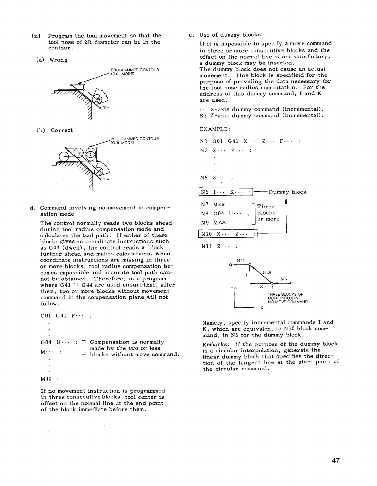
(ii) program the toolmovement so that the
toolnose of 2R diameter can be in the
contour,
(a) Wrong
PROGRAMMED
CONTOUR
e. Use of dummy blocks
If itis impossibleto specify a move command
in three or more consecutive blocks and the
offseton the normal lineis not satisfactory,
a dummy block may be inserted.
The dummy block does not cause an actual
movement.
purpose of providing the data necessary for
the toolnose radius computation. For the
address of thisdummy command, I and K
are used.
I:
X-axis dummy command (incremental).
K : Z -axis dummy command (incremental).
This block is specified for the
(b) Correct
CONTOUR
d. Command involving no movement in compen-
sationmode
The controlnormally reads two blocks ahead
during toolradius compensation mode and
calculatesthe toolpath. If eitherof these
blocks givesno coordinateinstructionssuch
as G04 (dwell), the controlreads a block
further ahead and makes calculations.When
coordinate instructionsare missing in three
or more blocks, toolradius compensation be-
comes impossibleand accurate toolpath cannot be obtained. Therefore, in a program
where G41 to G44 are used ensure that, after
them, two or more blocks without movement
command in the compensation plane willnot
follow.
EXAMPLE :
N1 GO1 G41 X“”” Z... F.. . ;
N2 X.”” Z... ;
N5 Z... ;
Three
blocks
or more
1
THREE BLOCKS OR
Dummy block
i
MORE INCLUDING
NO MOVE COMMAND
[N6 It.. K.. . ;l—
N 7
MXX
N8 G04 U.. . ;
N9 MM
N1O X.”. Z.. . ~
Nll Z“”” ;
I
GO1 G41 F.. . ;
G04 U.. . ;
M.. . ;
M40 ;
Ifno movement instructionis programmed
in three consecutiveblocks, toolcenter is
offseton the normal lineat the end point
of the block immediate before them.
Compensation is normally
made by the two or less
1
blocks without move command.
Namely, specifyincrementalcommands I and
K, which are equivalentto N 10 block command, in N
Remarks:
is a circularinterpolation,generate the
lineardummy block that specifiesthe direc-
tion of the tangent line at the start point of
the circular command.
6 for the dummy block.
If the purpose of the dummy block
47
Page 56

2.8.19 TOOL NOSE RADIUS COMPENSATION
(G40 THROUGH G44) (Cent’d)
EXAMPLE :
N1O GO1 Z... F.. . ;
x
N9
N8
COtdPEtisATION
(T–)
IN1l GO1 1(-a) K(-b) ;
N12 Mxx ;
N13 MOO ;
I
Dummy block
N14 MAA ;
]N15 G02 X.. . Z... 1... K.. . :1
N 16. .0 CENTER
I and K should be signed according to the
‘.
‘.<
b
Nll DUMMY BLOCK
(LINEAR LINE)
a
~yh : _=
&
/
–b
.
.
!1
N 10
type of the circulararc.
(M96 CIRCULAR PATH MODE)
RIGHT SIDE
COMPENSATION (T+)
+--+P--Z
Modificationof
sationmode
Itis invalidto
number by T code in compensation mode.
The originallyspecifiedtooloffsetnumber
remains validuntilthe compensation mode
is cancelledby G40 or T
However, the toolnose radius value may be
changed by varying the offsetmemory contents corresponding to the originallyspecified tooloffsetnumber, by means of MDI
operation. After thismodification,the new
tooloffsetnumber is made validbeginning
with the block newly stored in the prefetch
buffer.
0
tooloffsetvolume in compen-
newly specifya tooloffset
❑0 00 command.
BLOCK NEWLY READ AFTER
CHANGE OF TOOL NOSE
RADIuS VALUE
By dummy block N 11, the linearcommand
block of N 10stops at point A for the following circularmovement.
Switching between T + and T- in compensation
f.
mode
This compensation provides the switching
between T + and T- without canceling the
compensation by G40 or T
Eltl 00 command.
EXAMPLE :
N5 GOO T+O1O1 ;
Designates righthand side compen-
sationfacing the
N6 G41 X.. . Z... ; proceeding direction
N7 GO1 X.. . Z... F.. . ;
x.. . ;
N8
N9 T-O1O1 Z... F600 ;
Changes lefthand side
N1O X.. . F.. - ;
compensation
(7)
How to cancel compensation mode
a.
When G40 or T tl~00 is specified,compensationmode is cancelled,terminatingthe
toolnose radius compensation operation.
c
o
.%-!
I
%
~al
~-a .
Q)o
C& .
g.
L---
U G40 ;
TOlOO ;
TO1OO ;
G40 ;
---
-T(iioo;
48
Page 57

b. Upon terminationof compensation, the tool
center is offsetonto the normal lineto the
end point of the finalblock in compensation
mode, or the block immediatelybefore
that for which G40 or T
specified. (Consequently, ifa retracting
which resultsin acute–anglecontour is
specifiedin G40 or T
portionis produced. )
Then, the toolmoves so that the virtual
toolnose matches the end point of the move
command specifiedin G40 or T CID00 block.
EXAMPLE A :
(a)
(T+O1O1, G41)
G
o
.*
%
m
c“
W
~~ @ G02
~Z @ Gol U200 FO.25 ;
1’
@ GOO G40 XI.1O. z40.
@ TOlOO ;
❑000 has been
❑ ID00 block, no uncut
MOTION ON COMPLETION OF COMPENSATION
(GOO)
A-J
A’”
@
~--
+’
c. If the block of G40 (Nose radius compen-
sationcancel)does not have the move command, the virtualtoolnose moves to the
specifiedend point.
G40 (and T Do 00) commands contain movement.
Specify GOO or GO1 in the block previous to or
the same as G40.
other than GOO, GO1, or Gil, alarm ‘1027”willbe
activated.
EXAMPLE B : Move command is not included
in
G40 block for canceling compensation.
(c)
(T-0303, G41)
If the G code of 01 group is
(b)
(T+0202, G41)
MOTION ON COMPLETION OF COM-
PENSATION (GOO)
GO1 X.. . Z.. . F.. . ;
GO1 u24. FO.3 ;
GO1 G40 x80. Z40. F6. ;
GOO T+0200 ;
~ GO1 X... Z... F... ;
@ GO1 G40 F... ;
GOO T-0300 ;
(d)
(T+0404, G44)
J
@ G02 X... Z.., K... F.”” ;
@ GO1 G40 F... ;
GOO T+0400 ;
49
Page 58

2.8.19
(G40 THROUGH G 44) (Cent’d)
TOOL NOSE RADIUS COMPENSATION
QMOVEMENT AT
COMPENSATION
START BY 2
COMMAND
@
,,
,/’
/’
1’
–i–---––i
m
Note that, for each of above examples (a)
through (b), the toolcenter is temporarily
offsetonto the normal lineto the end point
of the block immediately before G04 or
❑000 command.
T
d. When tool nose radius compensation is can-
celledby the use of T
toolpositionoffsetcancel operationis performed concurrently with the operation at
toolnose radius compensation termination.
The canceloperationprovides the move-
ment in which the virtualtoolnose matches
the last specifiedpositionfor which tool
positionoffsethas been cancelled. If co-
existenceof these operationsis not desired,
cancel eitherof them by the use of G40
command.
CENTER
G 44
❑D 00 command, the
,--
J
/“ \
+-+3
NO INTERSECTION
--\ ~, /
/“
\,): ,’ , I
NO INTERSECTION
-.
%
(a)
\
-r+- ,
I
f
TOOL
$.-J&@
R/
(b)
(iii)When reversing command or an angle
closeto reversing command is program–
med in M97 (Outside Corner Circular
Arc Path Off) mode.
(a) Reversing command
‘\A ‘\A
(b) Command closeto reversing
Notes:
programmed shapes that produce input
a.
errors
(i) When programming an inside arc with tool
compensation,if programmed arc radius R s
toolradius d
~_—_
——
7
-.,
r
‘-) ~
r<d
9
(ii) When no intersectionpoint existson the
locus of the offsettoolcenter.
Outsjde compensation IS correctly
made even when r< R
In M96 mode, allof the above shapes are
correctlycompensated.
Interferencecheck
b.
To prevent the toolfrom cuttingdeeper into the
finishedshape than was programmed in advance.
Interferencecheck error is activatedwhen the
differenceof moving directionis 90° to 270° between
the programmed virtualtoolnose and compensated too
center. When an error is detected,the block prior
to the block in which overcuttingmay occur is
immediatelystopped and an alarm is shown.
This functiondoes not always prevent overcutting. There might be occasionswhen overcutting
is not detectedas an error or normal cuttingis
detected as an error.
50
Page 59

DIRECTION IS 180” DIFFERENT
N21 GOO TOlOO ;
N25 GOO T-0202 ;
TOOL RADIUS
COMPENSATION
TOOL POSITION
OFFSET
TOOL RADIUS
COMPENSATION
MODE WITH
TOOL NO. “02”
CANCEL
c.
G codes usable in compensation mode
As a rule G codes other than shown below
should not be used in the compensation mode.
Usable G codes
GOO, GOl, G04, G06, Gll
G 96, G 97
Constant surface speed control
G98, G99
Feed function designation
(G90, G 9t)
Absolute/incremental designation
G02,G 03,G12,G22,G23
Command includingcircular arc
G70, G71, G72, G73
. .Multiple repetitive cycle
Gill, GI12
Multiple cornering
(Beveling, rounding)
Remarks
I
Inhibited in
the block of
compensation
cancel or start
I
d. The subprogram (M98 or M99) may be speci-
fiedin compensation mode.
e. When the tooloffsetnumber is T code com-
mand of “00,” T
❑ 0 00 command has the follow-
ing two meanings:
(i) Tool positionoffsetiscancelled.
(ii)Tool nose radius compensation is cancelled.
The followingprogram can be specified:
N2 G41 ;
N3 GOO T+O1O1 ;
1
N40 GOO T0200 ;
N41 G40 ;
f. Inhibitionof MD I mode
(i)
ODeration in the MDI mode cannot be perf&med in the compensation mode. When
,RESET button is depressed, GOO (compensation cancel)becomes effectiveand
the operation in the MDI mode becomes
possible.
G40 through G44 cannot be writtenby the
(ii)
operationin MDI mode.
Command or operationfor canceling
compensation
The followingcommand or operation during
toolradius compensation, cancels the compensation completely or temporarily.
The command or operation should not be
performed:
Three consecutive blocks
1.
without move command
2.
MOO or MO1 command
M–code set by param-
3.
Temporarilyy
cancelled
eter for stopping
advance reading
(6 Max)
4,
G commands for stopping
advance reading G36,G37,
G38, G39
M02, M30 commands
5.
Reset operation
6.
Completely
cancelled.
,1
TOOL RADIUS
COMPENSATION
MODE WITH TOOL
llfJlll
NO.
Turning off power supply
7.
51
Page 60

2.8.19TOOL NOSE RADIUS COMPENSATION
(G40 THROUGH G44) (Cent’d)
h. Commands causing error
The followingcommands must not be given,
for they cause errors.
1.
G28, G29, G30
2.
G50, G51
3.
G74, G75, G76
4.
G90, G92, G94
5.
G31 - G35
6.
G68, G69
7.
G122, G123
i.
Even in M96 mode (toolnose radius compensation and circulararc path are on) , if
circulararc distancesAX, AZ are smaller
than the fixed values, the tooldoes not
followthe ,cornercirculararc path but moves
directlyto point B. The fixedvalues are
those which are setby parameter #6230.
.
_______
‘\
TOOL
MOVEMENT
‘\
,----------------------------------
,/’ COMPENSATION CANCEL
,
f
90. DIA
BEVELING ‘
3MM
R3 ROUNDING
20.
I
L-11 O.I- -90 l_70.
20.
I I
(a) Normal Insert
------- ----
DIA,
50.
15.
T*–
\
.
L,
I
30, DIA
20.
‘--YQYQliTiN-$F
OFWET MOTION ,,’ j
START
15. 20.
-
T+
,
I
+2
*
PROGRAMMED COMMAND
In case of AX/2 S NEGNR
S NEGNER
AZ
NEGNR:
EXAMPLE A :
Nl G50 x140. Z20, ;
GOO S1700 M03 T’+132132 ;
N2
N3 (cOO) G41 XO z5. ;
N4 GO1 ZO FO.2 ;
N5 X20, ;
N6 2-20. :
N7 X30. w-15. S11OO ;
N8 G12 w-ZO. 13. :
N9 Gll X50. K-3. S700 ; ‘BEVELING
N1O
GO1x-70,;
Nll
~22X90.Z-90.R20,s360;
N12
GO1 X11O. s300 ;
N13
G04 Uo ;
N14
(GO1)Z-11O.:
N15
X120.;
N 16
GOO X140. 230. T0200 ; ~OMPENSATION
N17
G40 ;
‘DWELL
_TOOL NOSE
—ROi.JNDING
COMPENSATION
START BLOCK
Constant value for
parameter setting
CIRCULAR
—ARC BY
RADIUS
NOSE
TOOL
COMPLETE BLOCK
J
TOOLNOSE
CO~PENSA-
TION
All ROUND INSERT
@
VIRTUAL
TOOL NOSE
I
(b) All Round Insert (G code to be used
is decided by settingside of virtualtoolnose.)
Fig. 2.33 Relations between G code and Sign of T Code
for Tool Nose Radius Compensation.
52
Page 61
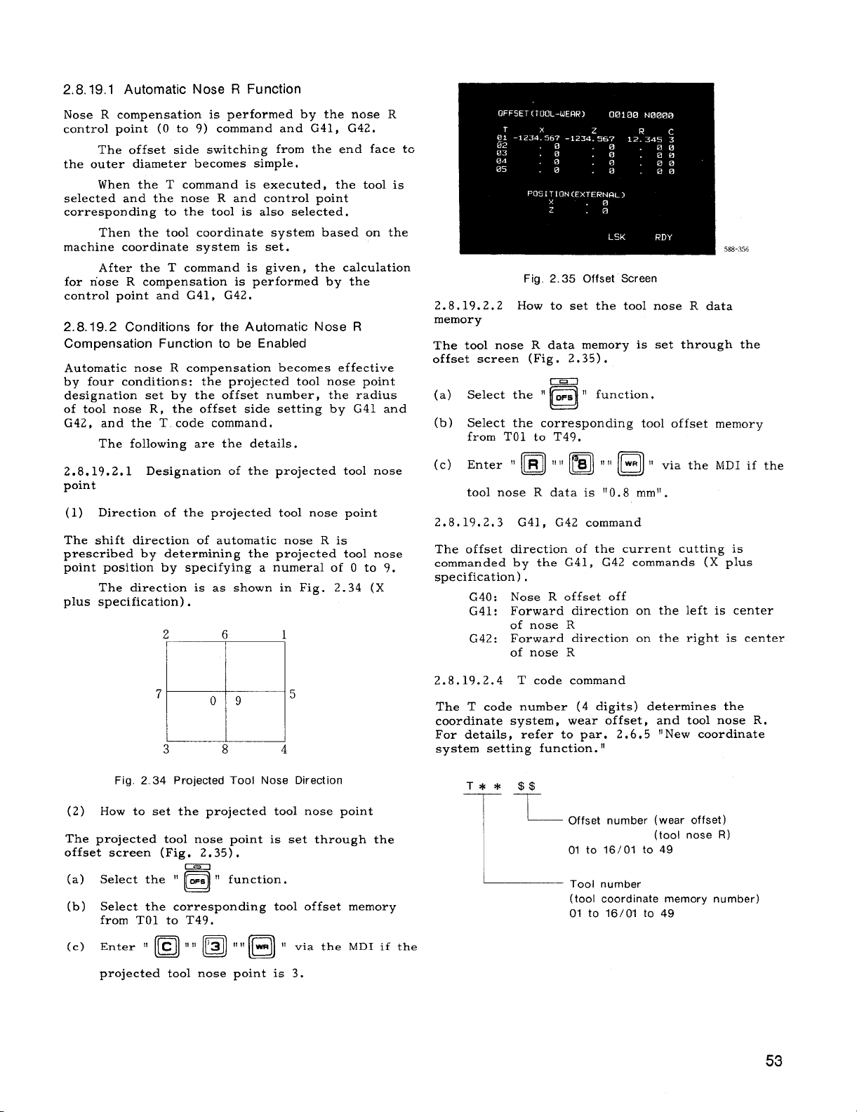
2.8.19,1 Automatic Nose R Function
Nose R compensation is performed by the nose R
controlpoint (O to 9) command and G41, G42.
The offset side switching from the end face tc
the outer diameter becomes simple.
When the T command is executed, the toolis
selectedand the nose R and controlpoint
corresponding to the toolis alsoselected.
Then the toolcoordinatesystem based on the
machine coordinatesystem is set.
After the T command is given, the calculation
for nose R compensation is performed by the
controlpoint and G41, G42.
2.8.19.2 Conditions for the Automatic Nose R
Compensation Function to be Enabled
Automatic nose R compensation becomes effective
by four conditions:the projectedtoolnose point
designationset by the offsetnumber, the radius
of tool nose R, the offsetside settingby G41 and
G42, and the T code command.
The followingare the details.
2.8.19.2.1 Designationof the projected toolnose
point
(1) Directionof the projectedtoolnose point
The shiftdirectionof automatic nose R is
prescribed by determiningthe projected toolnose
point positionby specifyinga numeral of O to 9.
The directionis as shown in Fig. 2.34 (X
plus specification).
2 6 1
588-356
Fig. 2.35 Offset Screen
2.8.19.2.2 How to set the toolnose R data
memory
The toolnose R data memory is set through the
offsetscreen (Fig. 2.35).
-
(a) Select the “ ~~s “ function.
El
(b) Selectthe corresponding tool offsetmemory
from TO1 to T49,
toolnose R data is “O.8 mm!’.
2.8.19.2.3 G41, G42 command
The offsetdirectionof the current cuttingis
commanded by the G41, G42 commands (X plus
specification).
Nose R offsetoff
G40:
Forward directionon the leftis center
G41:
of nose R
Forward directionon the right is center
G42:
of nose R
7
09
5
M
3 8 4
Fig. 2.34 Projected Tool Nose Direction
(2) How to set the projected toolnose point
The projectedtool nose point is set through the
offsetscreen (Fig, 2,35).
-
(a) Selectthe “ OFS “ function.
n
(b) Selectthe corresponding tooloffset memory
from TO1 to T49.
projected toolnose point is 3.
2.8.19.2.4 T code command
The T code number (4 digits)determinesthe
coordinatesystem, wear offset, and toolnose R.
For details,refer to par. 2.6.5 “New coordinate
system setting function.II
Offset number (wear offset)
(tool nose R)
01 to 16/01 to 49
Tool number
(tool coordinate memory number)
01 tO 16/01 to 49
53
Page 62

2.8.19.3 Offset Calculation of Automatic Nose R
Compensation Approach and Relief
The automaticnose R compensation functionhas
been improved from the nose R compensation
functionof the conventionalYASNAC LX3.
(Example) Tool nose point 3
(PARALLEL wlTH
2.8.19.3.1 The GOO + GOO block is not
compensated.
In short, positioningalone is
performed.
2.8.19.3.2 Compensation is performed for
approach GOO + GO1 (G02, G03) by settinga
projected vector (wall)on the toolto prevent
excess infeed or shock, as follows,
Compensation is performed for reliefGO 1
(G02, G03) + GOO, by settinga projectedvector
(wall)to prevent insufficientcut, as follows,
(1)
Approach GOO + GO1 or reliefGO1 + GOO
When the cuttingcommand move axis direction
(a)
is largerthan 45° against the Z-axis
(IX/21 >
IZI ), a projectedvector (wall)
parallelto the Z-axis is assumed, to calculate
the compensation with the cuttingmove axis.
The machine moves toward thiscalculated
position,
When the cuttingcommand move axis direction
(b)
is smallerthan 45° against the Z-axis
IX/21 < = 1ZI ) , a projectedvector (wall)
(
parallelto the Z- axis is assumed, to
calculatethe compensation with the cutting
move axis.
The machine moves toward thiscalculated
position.
‘//’
/
LARGER
THAN 45°
(PAHALLEL WITH
Z. AX!S)
t
b; ‘
/
+/
&/‘
&/
PROJECTED
/’.
‘1
PROJECTED ~/
VECTOR
SMALLER
THAN 45-
%
(2) Approach GOO + G02 (or G03) or reliefG02
(or G03) + GOO
(a) When the circularcutting command move axis
directionis larger than 45° againstthe
Z-axis, a projectedvector (wall)parallelto
the Z–axis is assumed, to calculatethe
compensation with the cutting move axis.
The machine moves toward thiscalculated
position.
co](C42)
——
.—— —__
GOO(G42)
PROJECTED
VECTOR
x
(b) When the circularcutting command move axis
directionis smallerthan 45Q against the Zaxis, a vector (wall)parallelto the Z-axis’is
assumed, to calculatethe compensation with
LARGER THAN 450
the cuttingmove axis.
The machine moves toward this calculated
position.
PROJECTED VECTOR
PROJECTED
VECTOR
x
(a)
—-
I
i~
SMALLER THAN 45
LARGER
THAN 45”
PROJECTED
VECTOR
z
z
%
(a)
~
(b)
(b)
Page 63

w
‘\ e
00
\
\/-
\c?
\ @
,)
\
\
\
-J
m
g
m
o
+
m
o
<
m
$
0
m
\
I
\
\
\
Page 64
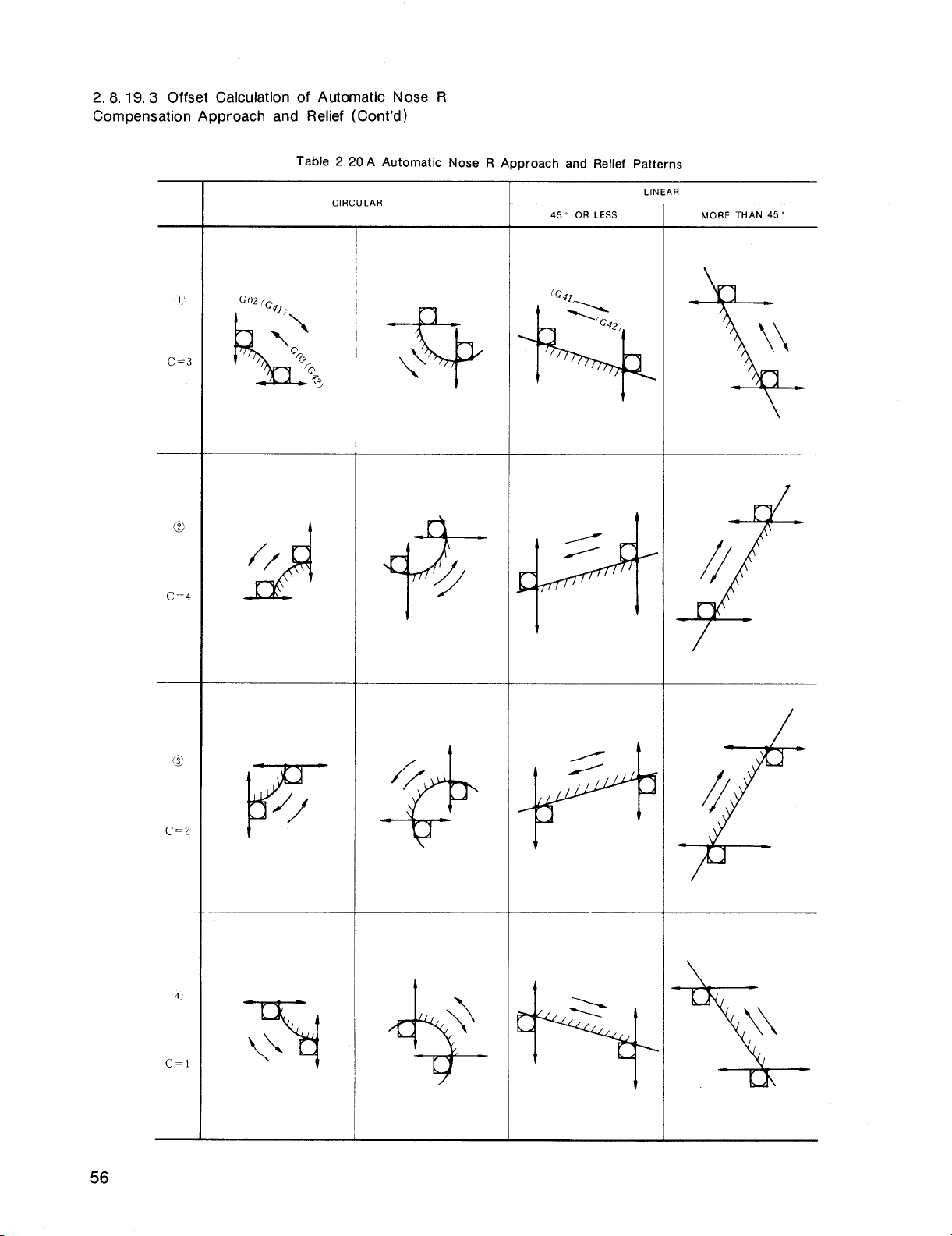
2. 8.19.3 Offset Calculation of Automatic Nose R
Compensation Approach and Relief (Cent’d)
Table 2.20A Automatic Nose R Approach and Relief Patterns
—
CIRCULAR
*
45s OR LESS
LINEAR
MORE THAN 45°
\\
X
C=l
—
t
4,
\
\
$
L
\\
56
Page 65

2.8.19.4 The G40 GO1 X Z I K
; Command
Cancel Function is Also Available in the Automatic
Nose R Function
The G40 GOO X Z I K_; command cancel
function (menti=ned~at~) , as wellas the same
functionby the GO1 command are available.
This makes a projectedwall by the I, K
commands in the block before the G 40 GO 1
command, to execute the nose R calculation,
Notes:
The nose R center is on the normal of the
1.
end point in the G40 GOO X Z ; block or
G40 single-block.
The nose R completecancel is performed in
2.
—.
the block immediatelybefore the G51 single-
block or G28 block.
The cross point is calculatedin the block
3.
immediatelybefore G40 GOO X Z I K ;
and the vector indicatedby “~, ‘K. ‘r —
4.
When GO1 and G41 (G42) are commanded at
the same time, the nose R center willbe on
the normal of the start point of the next
block.
However, in canned cycle, startup can
be performed by GO1 G42 of the firstblock,
but cannot be performed by repeating the
command later.
G40 GO1 X K
5.
; and G40 GO1 Z I
; are
of the sam~com—mand format as th~ ch~mfering
command, but the cancel functionhas priorit~
only when the G40 command is given.
2.8.20
(G 50)
PROGRAMMING OF ABSOLUTE ZERO POINT
ABSOLUTE ZERO
POINT (O, O)
A
Fig. 2.34
(2) G50 U... W... ; (IncrementalG50)
When the addresses U and W are specified
insteadof X and Z, the new absolutecoordinateis set up by adding incremental
values U (X-axis)and W (Z-axis)to the
absolutecoordinatepreviously set.
When the tools are very clifferent in length,
the incrementalG50 (addresses U, W) is
useful.
groups.
The tools should be divided intotwo
Then, the differencebetween the
length of the reference tooland that of the
second group of toolscan be set at the
incrementalG 50 command and an absolute
coordinate system can be stored.
G50 U1OO. W-1OO. ; 00. Settingof
PositionB
50 COMMAND POSITION
4X
POSITION OF
m
THE SECOND
GROUP
100.
B
50.
G
OF REFERENCE TOOL
(G50X Z ,)
A
+Z
Absolute coordinatesystem should be set before
move command.
coordinate system,
After setting up the absolute
allmotions can be commanded
on the absolutecoordinatesystem.
(1) G50 X.. . Z.. . ;
This command makes the present positionof
tooltipthe absolutecoordinates (X, Z) .
The values with a sign followingthe addresses X and Z are the distancesbetween tool
tip and the absolute zero point (O, O) to be
Therefore, itcan be said that “G50
set.
command specifiesthe absolute zero point.”
Fig.2.35
57
Page 66

2.8.20 PROGRAMMING OF ABSOLUTE ZERO POINT
(G50) (Cent’d)
Assume that the toolNo. 01 is reference
(3)
tool,and perform the setting of the following coordinatesystem for thistool:
G50 x80. z62. ;
then, selectthe toolNo. 02 which has the
toolpositioncompensation value shown in
the figurebelow and peroform the compen–
sationoperation,
to point”A.
N3 G50 x80. z62.
and the tool No. 02 moves
;
N4 GOO TO1O1 ;
4. When the power supply is turned on, the present positionof toolis set to the coordinate
(o, o).
Therefore, the absolutecoordinate
system should be set up before operation.
5. The current positionof the toolin G 50 coordinatesystem is shown in “POSITION
ABSOLUTE” of current positiondisplay,
6,
The coordinatesystem which was set is not
affectedby resetoperation.
The coordinate
system isreset by one of the followingoperations:
(i) The resetoperationby ORG key (see
4.3.4.2,POSITION ABSOLUTE) is performed.
(ii) G50 XO ZO
; command is writtenin MDI
mode and is executed.
(iii)The power is turned on again.
IN1O GOO T0202 ;
+x
G50 COMMANO
POSITION AT
TOOI NO 01
I
IU)L NO 02
~-= 40mm
~’z
Fig. 2.36
If the coordinatesystem settingis performed
with the referencetooland toolpositioncompensation is applied to the other toolas
shown above, the tool movement may be
programmed on a singlecoordinatesystem
for alltoolnoses,
Notes:
When T, S and M commands are programmed
1.
in the block followingthat containing G50,
GOO should be programmed in the block.
This designatesthe traverse rate for tool
offset motion.
G50 X.. . Z... ;
GOO S500 M03 TO1O1 ;
2.
G 50 is a nonmodal G code which is validonly
in the specifiedblock. Generally, the other
G codes, and M, S, and T codes cannot be
specifiedin the same block. Note that
G50 S.. .
;or G50 T.. .
separate feature and is not for coordinate
system setting.
; command is a
7. When settingwork coordinatesystem by G50,
parameter #6018 D7
can selectwhether Work
Coordinate System Shiftin 2.6.5 willbe ef-
fectiveor not.
2.8.21
MAXIMUM SPINDLE-SPEED SETTING (G 50)+
This functionis used for the controlprovided
with S 4–digitdesignationoption.
(1) G50 S.. . ;
Four digitsfollowingthe address S
specifiesthe upper limitof spindlespeed
in rpm.
If an S command exceeding the
limitis issued in subsequent blocks, the
spindle speed is governed at the upper limit.
In G 96 (Constant Surface Speed Control)
(2)
mode, when spindlespeed risesup too fast
as the current X-coordinate of the toolis
too small,the spindlespeed
s clipped
the limit.
EXAMPLE
G50 S2000 ;
The maximum spindle speed
is clipped at
2000 rein-l.
Notes:
1.
Maximum spindle speed specifiedby G50 can
be displayed on the CRT display.
Refer to
4.3.2.1,“Command DataDisplay.”
2. The specifiedmaximum spindlespeed is not
clearedby reset operation.
In case of S 4-digitdesignationB , unit of
3.
address S is not shown by rpm. Refer to
machine toolbuilder’smanual.
For S Z-digit
designation,thisfunctioncannot be used.
3.
G 50 should be commanded afterthe tooloff-
set and toolradius compensation are cancelled.
58
Page 67

2.8.22 WORK COORDINATE MULTI-SHIFT (G 50T, G 51)+
(2) Work coordinatesystem setting(G50T )
This feasureisused in combination with “5.2.3,
Measured Workpiece Value DirectInput”option.
Hence itisnecessary forthe programmer to be
familiarwith paragraph 5.2.3,
The purpose of thisfeatureis to retain a
“work coordinatesystem” with a certain point on
the work used as absolute zero point by perform-
ing G 50T coordinate system settingat the replace–
ment positionof each tool. In other words, programming may be performed with a singlecoordinatesystem throughout the entiremachining.
Tool coordinate value memory (number)
(1)
Itis necessary,before specifyingG 50T, to
a.
write the coordinatedata for each toolto
the toolcoordinatememory. For the writing procedure, see
pieceValueDirectInput.”
b.
The number of availabletoolcoordinate
memory units corresponds to the number
of tooloffsetmemory combinations as shown
below.
c.
For ease of use,
for toolNo. 01 in tool coordinatememory
No. 51, etc., as shown below:
TOOICoordinate Memory
51
52 02
5.2.3,“MeasuredWork-
write the coordinate data
I
Tool NO
01
a. G50 TEIEIAA
L
Specifiestool offsetnumber
(00 to 50)
L
Using this command, set the coordinate
system for each of X-axis and Z-axiswith
the followingwork coordinatesystem setting
value:
Work coordinate
system setting
value
Content of
programmed tool +
coordinate memory
[
Note :
the one which is shown in “POSITION
[EXTERNAL] screen of the current positiondisplay (POS) on CRT display.
b. Usually, specify
number specificationfieldAA .
EXAMPLE :
G50 T51OO ;
When the above program is specifiedwith
the toolslideat a given position(for
examDle, -x,
tion~isplay), the work coordinates~stem
defined by the operator is set correctlyas
shown below:
IIUnit current positionvalue” is
Specifiestoolcoordinate
memory number (51 to 99)
‘li~=el+
Content of
programmed tool
offsetmemory
H
“00” in the tooloffset
u “00” specifiesthe work
coordinatesystem setting
with the contents of tool
offsetmemory being zero.
-z in the unit current posi-
1
806——————
‘=’
is assumed that the toolcoordinatemem-
It
d.
ory containsthe followingcoordinatedata
Xtn and Ztn for each toolTn:
+Z
Ztri Tn
Am
*
‘ \&~~RAToR*T ~o~~ ~~~su~~D v~LI_I~
RK COORDINATE SYSTEM” SET BY
DIRECT INPUT’’OPERATION
Fig. 2.37
TOOL SLIDE AT THE
POSITION INDICATED
BY CURRENT POSITION
DISPLAY (O O)
(SEE NOTE 1)
30
t .x
T \ /
(< \
WORK COORDINATE SYSTEM
T1 WHEN TOOL SLIOE IS
AT A GIVEN POSITION
(–~, –:).
[/ ‘
}--r--- --J
2,,
T,
\
I
—, x,, 2
/
‘-’ 2)+X” 2 I :?S%IYS?E
(--z)*zt1
Fig. 2.38
I
~T,
T
1
WHEN TOOL SLIDE IS
+2
jSET WITH
THESE VALUES
Page 68

2.8.22 WORK COORDINATE MULTI-SHIFT (G 50T, G 51)+
(Cent’d)
c.
G50 TOOOO ;
By this command, the coordinatesystem is
set with the unit current positionvalue.
This means that the cancelingof the work
coordinate system settingis performed with
the centent of toolcoordinate memory = “O”
and the content of tooloffsetmemory = “0“
by the specificationof TOOOO.
(3)
Return to current positionorigin(G51)
a.
By G51 ; command, toolis returned to the
point at rapid traverse rate where the unit
current positionvalue is (O, O), on both
X-axis and Z-axis.
With a part program that uses work
b,
coordinate system setting,the machining
start point is the current positionvalue
(O, O) in principle. Hence, the use of G51
command facilitatesthe return to the start
point (O, O) aftercompletionof machining.
c.
G51 command should alwavs be specifiedon
.
a singleblock basis.
Notes:
1.
G50 T and G51 are nonmodal G codes which
are valid only for the specifiedblocks.
2.
When this function is used, set parameter
#6005D5to O (G50 preset of POS-EXTERNAL
displayis off).
3.
G51 ; command is equivalentto the following
two block commands.
m
Consequently, afterthe execution of this
command, the tooloffsetnumber is cancelled
together with the work coordinatesystem,
settingthe tool offsetnumber to “00.“
4.
When the G 50 T work coordinatesystem set-
ting is performed,
2.6.4,“Work Coordinate
System Shift” is made valid.
5.
The current positionof the toolin the set
work coordinate system is shown in the current positionvalue
“POSITION ABSOLUTE. “
It is not shown in POSITION EXTERNAL.
The work coordinatesystem set by G 50 T
6.
cannot be cancelledby a reset operation.
EXAMPLE A :
(The start point is current positiondisplay
(o, o))
N1G5OT51OO ;—
Work coordinatesystem
settingfor toolNo. 01.
N2 GOO TO1O1 M03 s1OO ;
Selectionof tool No. 01
(Note 1).
(Machining by toolNo. 01)
N20 GOO X. .. Z. .. ;— ~“~tioning ‘0 a ‘iven
N21 G50 T5200 ; — Work coordinatesys-
tem settingfor tool
No. 02.
N22 GOO T0202 ; — Selectionof tool
No. 02 (Note 1).
(Machinig by toolNo. 02)
N40 G51 ;—
Return to current position
display (O, O).
Note 1: The toolpositionoffsetin TO lO1
and T0202 commands may be used for the
compensation for tool wear.
When specified
during machining, the toolpositionoffset
may alsobe used for the compensation for
taper machining.
+x
~ w ~J(,, N) siTE?lR’T’ON
.,
v
----
T 02]
+Z
&
wORK COORDINATE SYSTEM
MACHINING BY TOOL NO 01, 02
CAN BE PROGRAMMED ON THIS
COORDINATE SYSTEM
Notes:
EXAMPLE B :
If the machining which was started by the
followingprogram is interrupted and the
program isrestarted without returning the
toolto the machining startpoint, the tool
correctlymoves to the firstapproach posi–
tion.
N1 G50 T51OO ;
N2 GO1O1 ;
N3 G96 S150 M03 ;
@ N4 GOO X20. z2.5 ;
60
Page 69

PROGRAM STARTED AT THE
POSITION OF CURRENT
/~~:~TION DISPLAY (-20 -ZTS)
R MACHINING INTERRUPTION
+x
TO1
T01
480.
40.
-1
B
()”).P
( /’ ,,,=,0
WORK
COORDINATE
SYSTEM
A APPROACH POSITION (20, 25)
TOOL COORDINATE MEMORY
51X=80
MACHINING START POSITION
‘:oUFiiENT POSITION DISPLAY
~z
This is because N1 G50 T51OO ; command
at point B performs coordinatesystem setting with the followingvalues to retainthe
work coordinatesystem, thus keeping
approach positionA unchanged:
X = (-20.) + (80.) = 60.
Z = (-27.5)+ (40.) = 12.5
EXAMPLE C :
This example shows a program for which the
replacement positionof each toolis different
from each other, and the values for work
coordinatesystem setting.
I N28 GOO T02020 M03 s800 ;
.
(Machining by T02)
N48 G51 ;
~ The coordinatesystem settingvalues
by this command are as follows:
X = (-50.) + 110. = 60.
z = (-35.) + 40. = 5.
T
02
MACHINING START
POSITION =
CURRENT POSITION
DISPLAY (O, O)
+x
I
z=5
t’
{Q
P-1=
C--J
b.
A-
40.
F- $ ‘
110DIA
Tw
[Q
F
47.5
100DIA
35.
T01
TO
–50.J2
I
Tool Coordinate Memory
No.
51
52
x
ICO,
110.
Iz
N1 G50 T51OO ;
N2 GOO TO1O1 M03 s1OOO ;
(Machined by TO1)
N25 G50 TOOOO
N26 COO x-50.
z-35. ;
...
Tool replacement position
of T 02 is current position
display (-50, -35).
47.5
40.
x=
30.DIA
--+
~
WORK GOORDINATE SYSTEM
2.8.23 MACRO PROGRAMS (G65 AND G67)
‘z
Specialprograms writtenby the machine builder
or user by the use of a group of instructionsare
registeredin the part program memory.
These
programs can be calledby the use of G65 or G66
command to execute them.
These specialprograms are referred to as the
macro program body, which can be written and
stored in the same format as a subprogram.
Page 70

2.8.23 MACRO PROGRAMS (G65 AND G67) (Cent’d)
Main Program
—
i
G65 P9001
(Argument
Designation)
User Macro Body
-09001 ;
)
[Variable 7
Operation Command
Control Command
I
L
)
i
-M99 ;
Main Program
Subprogram
No. ~
1 ~ Simple call
2 ! Modal call
3 I Call by arbitrary G code
: ~ a: ~::::
J
(1) Simple Call (G65)
G65 P.. , L.. .
The macro program, whose program number was
specifiedby p? is calledand is executed L times.
The default value of L is 1. When the designation of an argument to the macro program is
desired, specifyitin (argument designation).
tIArgument designation”
numbers to the ‘Ilocalvariables”used in the
macro program.
,,ARGUMENT DESIGNATION.”
(2) Modal Call (G66 and G67)
Type of Call
(argument designation) ;
For details, see 2.8.23.2,
Code ~ Remarks
I
G65
G66 G 67: For cancel.
Gxx
Mxx 1
Txxxx 4digits max.
I
is the assignment of real
However, unlike a subprogram, a macro pro-
gram allows:
(1) Use of variables.
(2) Computation between variablesor between
constants.
(3) Use of controlcommands such as a condition-
albranch.
to provide a generalizedprogram that requires
complicated computations and decisions.
program body from the main program makes it
possibleto assign the realnumbers to the vari–
ablesin the body.
program to run as a seriesof specificprograms
that provide toolmovements.
In thismanual, the macro program body is sometimes referred to as simply, “macro.“
2,8,23,
A macro program body
followingfive manners:
.-
These featuresenable the user macro body
The !targumentdesignation:in callinga macro
This enables this macro
1 Macro Program Call Commands
may be calledin the
G66 P.. . L.. .
This command callsthe macro subroutine specified
by program number P.
mand is executed, the specifiedmacro is run L
times.
G67 ;
This command cancelsthe modal callmode.
(3) Macro Call by Arbitary G Code
Gxx (argument designation);
This provides the command with is equivalent to
G65 P...
ten G codes of GO1 through G199 excluding those
designated by NC maker can be set by parameter.
The macro program numbers which correspond to
these G codes are as follows:
#6120 . . .
program number 09010.
#61Z1 ,..
program number 09011.
\
#6129 . . .
program number 09019.
Note: Macro callby arbitraryG code permits
only single nesting.
was calledfor by using arbitraryG code, M code,
or T code does not permit another macro callby
arbitrarycode.
(argument designation) ;. For Gxx,
(argument designation) ;
Each time a move com-
Sets G code which callsthe macro of
Sets G code which callsthe macro of
Sets G code which callsthe macro of
Namely, the macro which
62
Page 71

(4) Macro Call by M Code
(6) MultipleCall
G.. . X“”. Z“”” MXX;
This command may callmacros. In thiscase, the
macro is executed afterthe move command is
completed in that block, MF and M codes are not
transmitted.
ignated by parameter excluding MOO, MO1, M02,
M30, M90 through M99.
#6130 . . .
program number 09001.
#6131 ... Sets M code which callsthe macro of
program number 09002.
#6132 ...
program number 09003.
#6133 ... Sets M code which callsthe macro of
program number 09004.
NOTE THAT THE MACRO CALL BY M CODE
DOES NOT PERMIT ARGUMENT DESIGNATION .
When a macro M code is programmed in a
macro subroutine that has been calledby an ar–
bitrary G code or by a macro M or T code, itwill
be processed likea normal M code.
(5) Macro Callby T Code
Allthe T
mand.
G“”
With this
ber 09000
in the same block is completed.
Transmission of T code and TF signalis not per-
formed.
macro callcommand may be specifiedby the following parameter:
Parameter No.
#6134
o ... T code designationis handled as a T code,
1 T.. T code designationis handled as a macro
When a T code is specifiedas a macro call
command , the value designated by T “XXXX” (up
to decimal 4 digits)becomes the argument of
common variable#149,
MENT DESIGNATION OTHER THAN THIS IS NOT
PERMITTED .
macro subroutine that has been calledby an ar–
bitrary G code or by a macro M or T code, itwill
be processed likea normal T code.
For Mxx, four M codes may be des-
Sets M code which callsthe macro of
Sets M code which callsthe macro of
code commands provide a macro callcom-
X. Z.. . Txxxx ;
command, the macro of program num -
is executed afterthe ‘mov-ecommand
Whether a T code is to be used as a
callcommand to callthe macro of program
number 09000.
NOTE THAT THE ARGU-
When a T code is programmed in a
a.
G65 Simple CallAnd G66 Modal Call
As a subprogram is calledfrom another sub-
program, a macro program may be calledfrom
another macro program. Quadruple nesting is
permitted for simple calland modal callcombined. Multiplecallis disabledfor the macro
callby arbitrary ~ code, or M code or T code.
b. MultipleCall by G66 Modal Call
In modal call,each time a move command is ex-
ecuted, the designated macro is run.
alsovalidfor the move command in the macro
calledby multiplecall.
tiallyexecuted from the one designated latest.
Sample Program
G66 P9400 ;
GOO X1O. ;
G66 P9500 ;
Goo 220. ;
G67 ;
G67 ;
GOO 230. ;
1
09400 ;
GOO X40.
Goo 250.
M99 ;
09500 ;
GOO x60.
Goo 270. ;
M99 ;
2
The above sample program isexecuted in the
followingorder:
2.8.23.2 Argument Designation
Argument is the realvalue to be assigned to a
variableused in the macro program body. Ar-
gument designation,therefore,is the act of
assigning realvalues to variables. Argument
designationis of type I and type II, which can
be selectedas required.
(1) Argument Designation I
Argument may be designated in any address ex-
cept for G, L, N, O, and P. The relationships
between the argument designationaddresses and
the variablesare as shown below .
The macros are sequen-
@
B
@
MainProgram
o
Macro
o
@
(3
Macro
1
This is
Page 72

2,8.23.2 Argument Designation (Cent’d)
Address of
Argument Designation I
A
B
c
D
E
F
H
J
K
M
Q
R
s
T
u
v
w
x
Y
z
Variable in
Macro Program Body
#1
#2
#3
#7
#8
#9
#11
#4
#5
::3
#17
#18
#19
#20
#21
#22
#23
#24
#25
#26
For the address in which no argument need be
designated, the command may be omitted.
Sample Program
#1 #2
#24
‘f+ f
#2b
+
G65 P91OO L3 A30 B60 x34.8 z50.2 .
~
Argument Designation
Part
(2) Argument Designation1
A, B , and C arguments and 10 sets of I, J, and
.K arguments may be designated. I, J, and K
must be designated in this order.
The relationships between the argument designationaddress–
es and the variablesare as shown below.
Address of
Argument Designation
A
B
c
It
JI
K,
12
J2
K2
13
J3
KS
Iq
J4
Kd
15
J5
KS
1~
J6
KG
17
J7
K7
Is
Je
KfJ
IQ
Jg
KS
110
JIO
KIO
II
Variables in
User Macro Body
#1
#2
#3
#4
#5
#6
#7
#8
#9
#lo
#11
#12
#13
#14
#15
#16
#17
#18
#19
#20
#21
#22
#23
#24
#25
#26
#27
#28
#z9
#30
#31
#32
#*
The suffixes1 through 10 to 1, J, and K are determined by the order of the designated 1, J,
and K combinations.
For the address in which no argument need
be designated, the command may be omitted.
Sample Program
#4
#5 #6
#7 #9
+++++
G65P9005A. ..c. ..c. ..I...J. .. I...;...K...;
Argument DesignationPart
64
(3) Positionof Decimal Point in Argument
An argument may generally be designated with a
sign and decimal point.
For the designationwithout decimalpoint, the positionof decimal point is
as shown on the next page.
Page 73

Address in
Argument Designation
A, B
D, H
1,J, K, C I 3(2) I 4(3)
Metric Inch
Input input
3 3
o
10
M,S, T
Q
R I 3(2) I 4(3)
u, v, w
‘i, z 3 (2) 4 (3)
x,
:-+
\ 3 E’) I
4 (3)
The value shows the positionof decimalpoint
as counted from the leastsignificantdigit. The
value in parentheses indicatesthe number of
digitsthatfollowsdecimalpoint at the time of
parameter #6006-D5 = 1.
(4) Considerationsin Argument Designation
a, Argument designationtypes I and IImay
used concurrently.
If the same variable has
be
been
designated twice,the lastone is validated.
b. For both tv~es I and II.addresses 1, J ,
and
K should be de’s’ignatedin t-hisorder. T-heother
addresses may be designated in any order.
c. In the argument designationpart, negative
sign and decimalpoint may be used regardless
of the address.
(2)
Operation Commands
Arithmeticaloperations(+, -, *, /, “““)
a.
Functionaloperations (SIN, COS, ROUND, ...)
b.
(3)
Control Commands
Branch command (IF < qualification>
a.
GO TO n)
b.
Repeat command (WHILE < qualification>
DO m)” -
Using these commands, a program which requires complicatedoperationsand conditional
judgments may be writtenin the general format.
Hence, the featureof user macro is to enable the
programming of the wide range of NC functions
from a simplemachining cycle which is rather a
subprogram to a special,complicatedcanned cycle,
and the storingof these cycles in the machine.
Described below are detailsof the commands
mentioned above.
2.8.23.4 Variables
Instead of directlyassigning a value to an ad-
dress in a macro program body, the address may
be designated by a variable. When thisvariable
is calledduring execution,the corresponding
value is fetched from the variablearea to provide the address value.
There are three types of variables: local
variable,common variable,and system variable.
Each is identifiedby a variablenumber.
To the localvariables,realnumbers can be
assigned using the argument designationpart of
macro callcommand by G65 or G66.
(1) Local Variables (#1 through #33)
d. In G65 and G66 blocks, G65 and G66 should
always be specifiedbefore each argument desig–
nation.
This holds true with the macro callby
G code.
2,8.23,3
A macro program
Overview of Macro Program Body
body is programmed using the
combinationof the followingcommands.
(1) Variables
a. Local variable (#1 through #33)
b. Common variable (#100 through #549)
c. System variable(#1000 through #5104)
A localvariableis the one that is used for each
macro locally,
That is, when the localvariable
is used, the variablearea(#1 through #33) is
independently allocatedfor each macro call,
Certain values are stored by argument designation,
and the resultsof operationsin macro are
retained.
Page 74

2.8.23.4 Variables (Cent’d)
Main Program
—
G65 P9201
A.,.B.,.CS*. ;
Argument
Designation
o\~\
Single-levelMacro
09201 ;
G65 P9205
~:
ead/write
Enabled
#l =..,
#2.=...
#3 z,..
Local variablearea
for single-levelmacro
“ #1, #2, #3
Double-1evelMacro
~
09205 ;
#1
#2
#3
v
#l =...
#z =...
I
~
Local variablearea
for duplicate-levelmacro
I
Hence, the variables#1, #2, #3, ... of the
same macro assume differentvalues each time it
is called. Each localvariableis reset for each
macro calland is registeredby argument desig-
nation.
“blank.“ Each localvariableis set to “blank”
at the time of power-on and reset operations.
(2] Common Variables (#100 through #149, #500
throuth #549)
A common variable may be shared by allmacros
and through allmacros of allnesting levels.That
is, the common variable enables a macro to refer
to the result’sobtained by another macro.
The variable not designated becomes
Common Variable Area
a. #100 through #149:
are cleared at the time of power-on and reset
operationsand are set to
t~ols,they are not clearedby reset operationif
parameter #6008Dl is set at 1.
b.
#500 through #549:
are not cleared at the time of powe-on and reset
operations.
The common variablesare availableto the
user without restrictions.
designated by arguments. Indirectly,however,
they can be designated as follows:
~r—————l
These common variables
“blank.” In some con-
These common variables
They cannot be
mw
t-
Argument Designationof #1
(3) System Variables
Singe,JJAo.
Macro
Common variablesare divided into the following
two types depending on clearconditions:
Macro
Tripple-nest Quadruple-
Macro
nest Macro
A system variableis the one whose use is unique
to the system. There are followingtypes of sys-
tem variables:
a. Interfaceinput signals ... #1000 through
#1015, #1032T
b. Interfaceoutput signals ... #1100 through
#1115, #l132t
Page 75

c.
Tool offsetamount, toolcoordinatedata.
and toolwear amount ...
#2001 through #2050,
#2051 through #2080, #2081 through #2099, #2101
through #2150, #2151 through #2180, #2181
through #2199, #2201 through #2250
d.
Alarm message display ,,. #3000
e. Clock ...
#3001, #3002
f. Single-block stop and auxiliary-function
completionwait control.$. #3003
Feed-hold feedrate-override, and exact-stop
g.
control... #3004
h. RS232C data output ... #3100 (printout
feature).
i.
Modal information...
Positionalinformation,..
j.
#4001 through #4120
#5001 through
#5102
Note:
a. and b, may not be installed.
The interfaceinput and output signalsof
Follow the
specificationsof the machine toolbuilder.
The followingparagraphs describe the de-
tailsof the variablesmentioned above.
a. Interface Input Signals (#1000 Through #1015,
#lo32)t
YASNAC
1
20
21
22
23
24
25
26
27
28
29
c1
El
•1
❑
❑
•1
•1
c1
•1
UIO
UI1
U12
U13
U14
UI5
U16
U17
U18
U19
—–+
—–-----t
——--+
—–+
—–+
—–---t
—–_-----i
2’0H- ‘110—–’+
211
212
213
214 UI14~
215
E =a
UIll~
UI12~
UI13~
UI15—
i. When one of the system variables,#1000
through #1015, is specifiedto the right-hand
side of an operationalexpression, the on/off
stateof each of user–macro–dedicated 16-point
input signalsis read.
The relationshipsbetween
the input signalsand the system variablesare as
shown below,
fl1007 #1006 #lC05 #loO4 #1003
UI7
UI6 UI 5 UI 4 UI3
26
27
—
41015 #lo14 #lo13 #lo12 #loll
UI15
U 14 I-II13
~15 214
-%*
213
Variable
Value
24
25
+
UI12
2!2
F
1 I Contact Closed
o
Contact Open
#1002i#iooi moo
UI2
*3
22
#lOlO W09 ?!1008
11
UI
UI10
*
211
210
Input Signal
UIo
UI1
2’ 2°
U119 ~ UI 18
29 i 28
Each read variableis 1. 0 or O.0 when the associated centact is “closed”or “open” respectively,
regardless of the unit system of the machine.
ii. When system variable #1032 is designated,
the input signals(UIO through U115) that consist
of 16 points (16 bits)are collectivelyread as a
decimalpositivevalue.
#1032 = ~5# [1000 + i] * 2i
i =0
Sample Program
#1015 EQ O ] GO TO 100;
IF [
Bit 215 (U115) is read and, if itis IIO,!Ia branch
is made to sequence number N1OO.
#130 = #1032 AND 255
Bits 2° through 27 (UIO through U17) are collectivelyread to be stored in common variable#130
as a decimalpositivevalue.
Note:
System variables#1000 through #1032 cannot be placed to the left–hand side of operational
expressions.
67
Page 76

2.8.23,4Variables (Cent’d)
b. InterfaceOutput Signals (#1100Through
#1115, #l132)t
i.
When one of system variables#1100 through
#1115 is specifiedto the left-hand side of an
operationalexpression, an on or off signalcan be
sent to each of the user–macro-dedicated 16–point
output signals. The relationshipsbetween the
output signalsand the system variablesare as
shown below:
#llo7 #1106 #llo5
#llo4 #llo3
Uo7 UO 6 Uo5 Uo 4
27 2’5
#1115 #1114 #1113
Uo 15 Uo 14 Uo 13
15
2
25 24
14
2
2’3 I 2’2
VariableValue
1
#1112 #1111
U012 Uoll
#llo2 #llol
Uo 2 Uo 1
Uo 3
23 22 2’
#lllo #llo9
Uo 10 UC)9
210
2“
OutputSignal
Contact Closed
#lloo
Uo o
2’3
#1108
UO8
28
29
o Contact Open
ii.
When system variable#1132 is specified,the
output signals(UOO through U015) that consist
of 16 points (16 bits)are collectivelyoutput.
At thistime, the decimalpositivevalue substituted
in #1132 is output in the form of binary 16–bit
value.
#1132 = & #[1100 + i] * 2i
i=()
iii.With system variables#1100 through #1132,
the value sent lastis retained. Hence; when one
of them is written to the right-hand side of an
operationalexpression, itsvalue is read,
iv. Considerations
When any values other than 1,0 or O.0 are sub-
stitutedintoone of the system variables,#1100
through #1115, the values are handled as follows:
“Blank” and any values less than O.5 are assumed to be “O.“ Any values of O.5 and over
and other than “blank-”are assumed to be “1.“
Sample Program
#llo7 = #lo ; (#lo = 1.5)
Uoo
Uol
Uo 2
Uo 3
U04
Uo 5
U06
U07
U08
U09
Uolo
Uoll
U012
U013
U014
The output signal of bit 27 (U07) is outputted
in
the contact (closed)state.
#1132 = (#1132 AND 240) OR (#8 AND 15)
The output signal of bits 24 through 27 (U04
through U07) are outputted without change and
the contents of localvariable #$ are out utted to
the output signalsof bits 20 through 2 (UOO
?
through U03) ,
(Decimal 240 = 11110000 Binary 15 = 00001111)
c.
Tool Offset Amount And Tool Coordinate
Data, Tool Wear Amount
#2001 - #2050, #2051 - #2099, #2151 - #2199,
#2101 - #2150, #2201 - #2Z50
i. When one of the system variable#2001
through #2250 is specifiedto the right-hand
side
of an operationalexpression, the tooloffset
amount, toolcoordinatedata, and toolwear
amount can be read.
The relationshipsbetween the tooloffset
ii.
numbers and the system variablesare as shown
below:
U015
1
I
When 1.0 or O.0 are substituted in any of #1100
through #1115, the associatedoutput contactis
output in the “closed”or “open”state.
68
Page 77

‘“J
X-axis
Z-axis
syS@llVariable
#2001
#2i50
I
?/2101
to
#2150
I I
1
I
Tool Offset
Memory No.
01
to
50
01
to
50
Press ALM functionkey.
The alarm number and message and displayed on
the bottom of CRT screen.
—
ALARM
09100 NO054
I
Toe} Nose
Radius
““J
X-axis
iii.When one of the above system variablesis
specifiedto the left-handside of an operational
expression, its value can be changed.
Sample Programs
#116 = #2016 ;
The contentsof tooloffsetnumber 16 for X-axis
are substitutedfor common variable#116.
#2201
to
#2250
SYstern Variable
#2051
#2t;99
1
I
01
to
50
Tool Coordinate
Memory No.
51
to
r30
I
USERS MESSAGE
I
550. MACRO ERROR:
1: :‘ATA%x!!_l
t
Message displayareaand
sample display
When RESET key is pressed afterremoval of the
cause of alarm, the message display and the alarm
statecan be cleared.
Sample Program
#3000 = 550 (MACRO ERRoR: DATA OVER-
e. Clock (#300L, #3002)
i.
When system variable#3001 or #3002 for clock
is specified,the clock can be read.
FLOW )
“ALM “
#2081 = #24 ;
The toolwear amount (memory No. 81) of X-axis
is erased and the contents of localvariable#24
are set.
d. Alarm Message Display (#3000)
When a conditionto be alarmed occurs in a user
macro program, system variable#3000 may be
specifiedto put the machine in the alarm state.
i.
#3000 = n (<alarm message>) ;
using thiscommand, specify the alarm message
(lessthan 32 characters) preceded by a 3-digit
alarm number n and enclosed with control-inand
control–outsymbols.
be three digitsand not be one used by the machine.
ii. When this
or “A/B” is displayedon the bottom of CRT
screen regardlessof the mode and function.
Itsmessage can be seen by the followingopera-
tion:
#3000 command is executed, “ALM”
The alarm number should
ii. To preset the clock, substitutethe value with
thissystem variableput at the left-handside of
the expression.
Sample Program
#3001=o; ...
iii.Restrictions
The accuracy of
4294968000
occrus, settingthe clock to “O.‘t
The accuracy of clock 2 is 8 ms. When
429496800 sec has been reached, an overflow
occurs, settingthe clockto “O.”
The clock is preset to value “O.“
clock 1 is 8 ms.
rnsec has been reached, and overflow
When
69
Page 78

2,8.23.4Variables (Cent’d)
Sample ProPram
Sample Program
=~z::::
Macro Program
09351 ;
#3002 = O ;
WHILE [#3002 LE #1 ] DO1 ;
END 1 ;
M99 ;
f. Single Block Stop And AuxiliaryFunction
Completion Wait Control (#3003)
When the value listedin the followingtableis
substitutedin system variable#3003, the single
block switch can be disabled or the next block
may be entered without waiting for the checking
of the finishsignal(FIN) of the auxiliaryfunc–
tion (MST) .
SpecialThreadcutting Cycle (Incremental
Command)
TX
o—— ——;oo—–.–-—o —
—
Macro Call
G65P9093u- o.. w-. K.00F0F. .. ;
[[
tz
~ #9: Lead
1-
%: Without sign,
radius value
#23: Negative value
#21: Negative value, diameter
value
When the finishsig~alis not waited for, the
distributionend signal(DEN ) is not transmitted.
In this case, the FIN is waited for in the block
with the check skip cleared. Hence, when the
FIN is not waited for, be carefulnot to specify
the next auxiliaryfunction.
Feed-Hold, Feedrate-Override, And Posi-
~.
tioningCompletion Control (#3004)
When the value listedin the followingtable is
substituted in system variable #3004, feed hold,
feedrate override, and positioningcompletion
can be made valid or invalid.
#3004 Feed Hold
Feedrate
I
Override Completion
Positioning
~
Macro Program
09093 ;
M93 ;
#10 = ROUND [#6] *2 ;
#11 = ROUND [#21] +#10 ;
#12 = ROUND L#23] +#10 ;
#3003 = 1 ;
GOO U#ll ;
#3004 = 7 ;
G22 U-#10 w-#6 F#9 ;
G32 w#12 ;
G32 U#10 w-#6 ;
#3004 = o ;
GOO U-#11 ;
GOO w-#23 ;
#3003 = o ;
M92 ;
M99 ;
Buffering 4 blocks
Singleblock switch
invalidated
Feed hold invalidated
Feedrate override invalidated
Positioningcompleted
L
m
4
5
6
7 Invalid ~
70
Valid
Invalid
Valid
nva I
Valid Invalid Invalid
Invalid i
Invalid
Invalid
Page 79

h. RS232C Data Output (#3100)
When system variable #3100 is specified,messages
and NC internaldata can be output to external
equipment via RS232C data inputloutput interface.
If the external equipment is a printer, the above
informationis printed.
Output of Messages
i.
#3100 = (<Message>)
When thiscommand is specified,the message
enclosed by control-inand control-outisoutput,
via RS232C interface.
Each output message is followedby CR/LF
(Carriage Return /Line Feed) . Hence, when
#3100 = ( ) is specified,only CR /LF is outputted,
which is useful in tabulatingthe punched data.
Note:
When the message is output, it should be
enclosed by control–inand control–out.
ii. Output of Data
#3100 = [< variable >]
PrintoutData
TOOL OFFSET 01
x
UUUUII), OI)OOUUU-10, ()()00 UUWUU13,80000
t
z
1
R
,
,
A maximum of 6 digits(data plus signs)
before the decimal point can be output.
i.
Modal Information(#4001 Through #4120)
i.
When one of svstem variables #4001 throueh
#4120 is specifiedj the modal commands that &e
specifiedUP to the immediately preceding block
can be known.
These modal commands are sometimes calledthe current values of modal informa–
tion commands.
System Variable
#4001
Modal Information
G code (group 01)
When this command is specified,the value of the
localvariable,common variable, or system varia-
ble at the right-hand side is output via RS232C
interfaceas plus or minus decimal 9 digits (4
digitsafter the decimal point, 5 digits before the
decimal point) data,
Notes:
1. The value is rounded out to the fifthdigit
after the decimalpoint.
Z. When the value is of 6 digitsor more before
the decimalpoint, the asteriskisoutput.
iii.The above output isperformed when system
variable#3100 isexecuted in the macro program.
Itis required, therefore,to previously attach
the external equipment such as a printer via
RS 232c interfaceand preset the parameters that
use the interface,
Sample Program
#3100=( ); . . .
Carriage return/linefeed
#3100 = (TOOL OFFSET 01);
#3100 = (LJU
#3100 = [#20011; . . . =
XUUUUUUUULJU
z UUUUUUUUUU R);
10.000 mm
#3100 = [#2101]; ... =-10.000 mm
#3100 = [#2201]: ... = 0.800 mm
#3100 = ( ) ;
# 4021
#4108
#41c9
#4114
#4115
#4119
#412Q
Notes:
M code can not be read out because of non-modal
1.
information.
The value of either E ( #4108) or F ( #4109) is specified
2.
just before being stored, giving # 4108 and # 4109 the
same value.
ii.
through #4120 cannot be placed to the
#4001
code (group 21 )
G
E code
F code
Sequence number
Program number
S code
T code
left-hand side ~f the operationexp-ression,
Sample Program
Main Program
G65 P960Z <Argument Designation> ;
71
Page 80

2.8.23.4Variables (Cent’d)
Macro
Program
09602 ;
#1 = #4001 ;
GOO X...O,;,;
– G codes (GOO through
G03) of 01 group are
retained.
GO1 Z...00;0;
G03 X.. .O. R.;...;
GOO Z.. . ;
G#l ;
M99 ;
PositionalInformation (#5001 Through #5102)
j.
— G codes of 01 group
I
are restored.
I
When system variables#5001 through #5102 are
specified, various positionalinformationcan be
obtained.
The unitof the informationismillimetersor inches.
\
%1
1
Unit
System
Variable
$5061
?#5062
#5081
$5082
F5101
#5102
Note: Reading of #5021, #5022, #5041, #5042, #5101,
and #5102, when commanded during movement, will be
performed after completion of the movement. Accordingly, nose radius compensation is not performed.
Mnemonic
Meaning
Positional Information
X-axis skip signal
position (ABSKp)
Z-axis skip signal
positon (ABSKP)
X-axis tool offset
amount
Z-axis tool offset
amount
X-axis servo position
deflection amount
Z-axis servo position
deflection amount
ABSIO
End position of
block
immediate y
before.
ABSMT ABSOT ABSKP
Command
current
position
(same aa
Pos.
MACHINE
display).
Read During
Move
Enabled
Enabled
Enabled
Command
current
rmsition
(same as
Pos.
ABSOLUTE
display).
(Note)
(Note)
Position
at which
skip signal
did not go
on in G31
block.
=
Coordinate
System
In the macro program body, the “input unit x 10”
featureis invalid. Tool
Position
System
Variable
#5001
#5002
+502 1
T15022
#5041
#5042
Positional Information
X-axis block end
position (ABSIO)
Z-axis block end
position (ABSIO)
X-axis current
pcsition (ABSMT)
Z-axis current
position (ABSMT)
X-axis current
rxxition (ABSOT)
Z-axis current
oosition (ABSOT)
Read During
Move
Enabled
Enablw)
Enabl!dote)
Offset
Tool
Radius
Compensation
Amount
Notes:
1. When the skip signal is not turned on in G 31 block, the skip
2. The “input unit x 10 feature is valid up to the macro call
3. System variables //5001 through #5102 may not be placed to
Work
coordinate
system
Not
included
Not
included
signal position is at the end of G 31 block.
blcck (the argument designation part by G 65 or G 66) but is
in valid in the user macro WY.
the left-hand side of operational expression.
Machine
coordinate
system
—
/“’”
/’
Wo$k
coordinate
system
Included
Included
Wofk
coordinate
system
Included
included
72
Page 81

Sample Program
The toolis positionedto the specifiedlocation
(X, Z) on machine coordinatesystem, performs
the specifiedM feature,and returns to the start
point.
Main Program
Variable
No.
# 1 to #33
#loo to #149
#500 to #549
#looo to #lo15
List of Variables
.ocal variables.
;ommon variables (reset to “blank at
)ower-off).
>ommonvariables (retainad at power-
)ff)
nterface input signals (each signal for
?achbit).
?
I
L #24
Macro Program
09603 ;
#1 = #5001 ;
#2 = #5002 ;
G91 ;
GOO X [#24-#5021] ;
GOO Z [#26-#5022];
M#13 ;
Z#2 ;
GOO
GOO X#l ;
M99 ;
~#26
#1032
#lloo to #1115
#1132
#2001 to #205C
#2101 to #215C
#2201 to #225C
#2051 to #208C
#2151 to #218C
#2081 to #209$
#2181 to #219$
#3000
#3001
#3002
#3003
#3004
#3100
#4001 to #412(
#5001 to #500
#5021 to #502
#5041 to #5rJ4
#5061 to #506
#5081 to #508
#5101 to #510
nterface input signal S #[1000+
nterface output signals (each signal for
?achbit).
nterface output signal S #[1100+
rOOioffset amount
X-axis, Z-axis, nose radius)
rool coordinate data
X-axis, Z-axis)
rOOiwear amount
X-axis, Z-axis)
Alarm message display.
Wck 1 (In units of 1ms).
Clock 2 (in units of 1s).
Single block stop, auxiliary function
complete wait control.
Feed-hold, feedrate-override, and
exact-stop control.
RS232 C data output (printout feature).
Current value of modal information
command.
End pcsition of the immediate
preceding block (for each axis).
Current position of machine coordinate
system (for each axis).
Current position of POS. UNIVERSAL
(for each axis).
Position at which G 31 skip signal is
turned on (for each axis).
Effective tool position offset
amount (X-axis, Z-axis).
Servo position deflection amount
(for each axis).
(
,=~
(
,=
0
i] * 2 i
i] * 2 i
).
).
73
Page 82

2.8.23.4Variables (Cent’d)
Variable Representation
(4)
Each variable is represented in a variablenumber
that follows#.
a.
How to designate a number directly:
#i(i=l ,2,3, 4,0..)
&Z!22E&
How to designate an expression as a variable
b.
number:
# [<expression>]
Sample
In the followingdescription,variable#imay be
replaced with variable#[<expression >].
#lo
#130
#2000
# [#loo]
# E#500 +
#
~#2012-J
lJ
S2!2.F&
(i) When #1 = 45.2346
x#l ...
(ii) When #2 = 0.255
F#2 ...
(iii)When #3 = 5.37672
G04 P#3 ...
(iv) When #4 = 2.7236
M#4 ... M03
G#4. ..Go3
4. Value for each address should not exceed
the maximum programmable value.
5. The value that followsan address may be
replaced with <expression>.
6. The constant without decimalpoint enclosed
in brackets [
point at itsend.-
(6) Undefined Variable
= X45. 235 mm (formetric input)
= FO.26 (mm/rev)
= G04 P5.377 (see)
1 isassumed to have a decimal
(5) Variable Reference
a. The value that followsan address may be
replaced by a variable.
When < address> #ior <address> -#iis specified,
the value of the variableor itsnegative value
(complement, more exactly) is made the specified
value of the address.
Sample #30= l.o;
The above specificationis equivalentto the
specificationbelow.
GO1 x1OO.
Notes:
1.
Address 1, 0, and N may not refer to varia-
bles.
Sample
2. A variablenumber may not be replaced with
a variable.
#lol = 100. ;
#lo3 = 300. ;
#140 = o. 3 ;
G#30 X#l Ol Z-#102 F#140 ;
Z-300. FO.3 ;
/#8, N#100 ... Error.
The value of an undefined
be ‘Iblank.“ An undefined
followingsituations:
a.
The localvariablefor which argument desig-
nation was not performed in macro callcommand.
Common variables #100 through #149 at the
b.
time of power-on and reset operations.
c. The localvariablesand common variables
for which the values were not written from MDI
panel.
Designation and functionof <blank> is classified
in the followingtwo versions A and B. The
controlis set
versions A to
changed.
For eitherversion. Switching from
B and from B to A cannot be inter-
variableis assumed to
variableoccurs in the
Ss!2.Pk
3. When a variableisused as address data, the
values below the leastsignificantdigitare rounded.
##20 ... Error.
#[#20] ... Correct.
74
Page 83

Version B
‘#0 defined as
variables of
<blank>.
-Commanding
#O at the lefthand
side of the
equation,
—
-Where #2 is
<blank>, com-
mand #3 =#2;
means
#3= <blank).
‘Where #2 is
<blank>, command600 X#2;
is equivalent to
command G 00;
(Address is
ignored.)
“Where #2 is
(blank),
#3 is O.
@Condition
“IF #3 EQ #2” is
established.
@Condition
“IF #3 EQ #2” is
established.
– In these command,
#3 = (Blank)
:oncept of #0.
Variable <blank>
is commanded in
the replacement
equation.
Variabla <blank)
is commanded
in the part
program.
Variable <blank>
is commanded
in the condition
of EQ and NE.
Others
Version A
No conception
of #o.
Commanding #0
causes alarm.
‘Where #2 is
<blank>, command #3 = 1#2.
means #3 = O.
)Where #2 is
(blank),
command 600 X
#2; is equivalent
to command G 00;
GOOXO;
“Where #2 is
<blank>,
#3 is O.
@condition
“IF #3 EQ #2° is
established.
@Condition
“IF #3 NE #2” is
not established.
#3 =# [#o+#ol
#3=#2 *#O;
#3=#o+#o;
#3=#ol#o;
#3=5* #o;
#3=2–#O; means #3=2
#3 =5/# O; causes alarm.
(Blank> in the replacement described
above is treated as “0.”
“Condition
when #2 and #3 are <blank), or
#2 is O and ??3is <blank>.
-Condition IF?/3 LT#2 is not
established when #2 and ti3 are
(blank), or *2 is (blank),
and F3 =0.
In these
commands,
f#3=o.
1
IF #3 GE#2 is established
2.8.23.5 Operation Commands
Various operations can be performed between
variablesand between variablesand constants.
The operation expression is represented in the
form of #i = (expression> . in which <expression>
is a general arithmeticoperationalexpression produced by combining variablesand constants with
oPeratOrs and functions.
The availableopearatlonsand functions are as follows. Instead of
~ and #k, constants may be used.
(1) Variable Definitionand Replacement
#i= #j ... definition,replacement.
(2) Add-Type Operations
#i=#j+#k ... Sum.
#i = #j- #k ... Difference.
#i=#j OR #k...
Logical sum (foreach of
32 bits).
#i=#j XOR #k””.
Exclusive logicalsum
(foreach of 32 bits).
(3) Multiply-Type Operations
#i= #j* #k ,.. Product.
#i = #j I #k ... Quotient.
#i = #jAND #k. .. Logicalproduct
(for each of 32 bits).
Note:
In OR , XOR, or AND operation,the
variablevalue (or constant) is converted into
the binary 32–bitequivalentand the operation
isperformed on each bit.
(4) Functions
#i= SIN [#j] ...
#i=cos [#j] ...
#i= TAN [#j] ...
#i
❑ ATAN [#j/#kl
#i=sQRT [~] ...
#i= ABS~#j] ...
iYi=BIN [~] ““-
#i- BcD [#j] ...
#i ‘ROUND [#j] ...
#i=FIx [I/j] ...
#i= FUP [#j] ...
Sine (indegrees).
Cosine (in degrees).
Tangent (in degrees).
...
Arctangent .
Square root.
Absolute value.
Convert from BCD ,
Convert into BCD.
Produce integer by rounding.
Truncate the fractions.
Raise the fractionsto a unit.
(5) Combinations of Operations
The above operationsand functions may be used
in combinations.
formed first.
performed.
A functionaloperationisper–
Then, a multiply-typeoperationis
An add-type operationisperformed
last.
Sample
#i .//j+
‘k * SIN [#L]
a)
@
@
w
75
Page 84

2.8.23.5Operation Commands (Cent’d)
Change of OperationalOrder by [ ]
(6)
Prioritymay be given to an operation by enclosing itin brackets [ ] . Up to quintuple (fivehold) nesting of brackets is permitted including
those of functionaloperations.
Sample #i = SIN
[[fi+#k]*#k+ti]*k
[
1
CD
‘T!-l
Q
@
I
(7) Considerations for OperationalCommands
a, The constant without decimalpoint used in
<expression> is assumed to have a decimalpoint
at itsend.
b. When used in conditionalExpression IF or
WHILE, functionROUND truncates the fractions.
C. When used in address data, functionROUND
rounds off the part below the leastsignificant
digit.
Y
@
I I
This is because the data of #10 and #11 in @
and @ blocks are substantiallyrounded before
being executed.
If @ block is
@ GOO U- [#10 +#11] ;
then, the movement is made by the following
amount:
U- [ #10 + #n] = U - [12.3758 + 13.1236]
—
On the other
@+@is
u#lo + u#ll
Hence, the program of@ is not correct.
(8) Operational Errors
The data format and the operationalerrors in the
macro programs are as follows:
Data Format
a.
The numeric data handled in macro programs are
of the floatingpoint format.
r~
= U - [25,499A]
—
= U - [25.499]
hand , block movement of
—
- U12. 376 + U13. 124
= U25.500
Sample (a)
#10 = 12.3758
When the least
X is 0.001 mm,
GOO X I ROUND c #loll;
means
GOO x12.376 ;
because 8 of 12.3758is rounded.
This command is alsoequivalent to
GOO X#10 ;
Usually, ROUND is not used as mentioned above;
itis used as shown below:
sample (b)
When ROUND is used as follows,the program re-
turns to the startpoint correctly:
@ #11 = 13.1236 ;
@ GOII U#10 ;
@ GO1 U#ll F.. . ;
(Q GOO u- [ROUND [#lo] + ROUND [#11]];
L
significantdigit of address
the followingcommand
–J
‘ RETRACTION
— +x
where, M is sign + data 52-bitbinary,
b. OperationalErrors
Each time an operation is performed, the following error is caused and is accumulated. The number of significantdigitsis 15 to 16, which compensates the error sufficiently.
2.8.23.6 Control Commands
The commands which control the flow of the
micro–program are of the followingtwo types:
a. Branch command ...
ssion>]GOTO n ;
b. Repeat Command ...
expression > ] DO m ,
(1) Branch Command
a. IF [K conditionalexpression >] GOT() n ;
If< conditionalexpression>ofthiscommand is
established,a branch is made to the block of
sequence number n within the same program.
When a variable or an expression is used for n,
the branch destinationmav be changed. If the
conditionisnot satisfied,the program proceeds
to the next block.
E is sign + data 10-bitbinary.
IF [f conditionalexpre-
WHILE [< conditional
Page 85

SimpleBranch
..
Established
-
..
Leapisbrokenuponestablishmentofcertaincondition.
I
Repeat
/
Unestablished
Repeat
____l_J
m
z
u
3
..
-W
Ei”
N
v
..
Page 86

2.8.23,6 Control Commands (Cent’d)
DO 1
Cl
END 1
DO 2
The valueofm, 1, 2,or 3
iscalledthe identification
number, which isused by
DO and END tocalleach
other.
(iii)
DO1;
DO 2
END 1
1
OverlapofDO
rangesisnot
permitted.
Rewriteas
shown right.
DO 1;*
D02;
1
END 2 ;
ENDl; —
-1
‘1
END 2
3. The same identification number may be used
repeatedly except where repeat ranges overlap.
4. To get out of a DO loop, a GOTO n can be used.
However, a GOTO n does not enable entrance to a DO
loop as shown below :
m=
L--
5. Triple DO-loop nesting is permitted for each
micro program.
I
L--
2
1:
DO1;
D02;
D03;
G65... ABC ;,
END 3 ;
END 2 ;
END 1 ;
DO1;
D02;
D03;
4“
G65... XYZ ;
END 3 ;
END 2 ;
END 1 ;
(iv)
(v)
I
J
END 2 ;
DOI:
D-O2 ;
D03;
DO1;
:7
END 1 ;~
END 3 ;
END 2 ;
END 1 ;
DO1;
‘7000””;~
END 1 ;
Quadruplenesting.
Max. nestingpermit-
tedistriple.
Do loopmay not
be enteredfrom
outside.
i
-=--.-/
Enabled
6. The codings shown below cause an
(i) DO1;
DO1;
~
END 1 ;
(ii) DO1;
‘1
END 1 ;
END 1 ;
1
i
The returndestination
?
ofEND 1 isunknown.
One END 1ismissing.
Enabled
error:
GOTO 7000; J
I
IF,..
7. Do not put space between command and value m,
such as DOm and ENDm. Error occurs if space is placed
between these entries.
2. 8.23.7 Registration of Macro Programs
(1) How to Make Registration of Macro Programs
The registration and edit of macro program bodies are per-
formed in the same manner as usual part programs and
subprograms. Therefore, no program size restriction that
applies to the user macro body. Part programs, subpro grams, and macro programs may be stored together in the
part program memory to their full capacity.
(2) Classification of Program Numbers
The program numbers are classified into the
following :
Page 87

program No. I Classification
08000 to
08889
o 9CO0 to
09999
+
2.8. 23.8 Display and Write of Local and Common
Variables
Local variables (#1 through #33) and common var-
iables (#100 through #149, #50Clthrough #549)
can be displayed and written by the following
operations:
When D4 of #6004 is set to 1, the
registration, erase, and edit of
programs are disabled,
When D7 of #6021 is set to 1, the
registration, erase, and edit of
programsare disabled.
(2) Write Operations
Writing of Values to Variables
a. Press SET function key. Mode select position
may be provided anywhere.
Key-in the variable number to be written
b.
‘ress m ‘ey ‘r L2iiiJ ‘ey ‘Ow-
ever, # need not be keyed-in. The keyed-in
variable number is specified and the cursor is
positioned to it.
c. Key-in the value to be written. Press WR
key.
of the variable number with the cursor position–
ed,
The keyed-in value is stored as the data
(1) Display Operations
Display of Variables
a. Press SET function key. Mode select position
may be provided anywhere.
Kev-in the variable number and Dress
b.
CURSOR k
m
need not be keyed in. Ten sets of variable numbers including the specified variable number and
their data are displayed. The data are displayed
in the signed 8-digit integer part and the 8-digit
fraction part.
Press ~
c.
display may be~crolled up or down.
Remarks
a. Common variables may always be displayed
for review .
b. For local variables, those of the macro cur-
rently executed are displayed.
when a macro of a nesting level is in execution,
the local variables belonging to macros of the
other nesting levels cannot be seen.
variables after completion of execution are all
rest to “blank. “
‘y ‘r m ‘eye ‘:wever ‘
I—Macro nestinglevel
(0: hlacron;t]nexecution)
SETTING !JACRO
-LEVEL O
#oloo
#olol
#olo2 3.00000000
#olo9
L-
Sample Display of Common Variables
PAGE key or
-12345678,12345678
E-l
01234N0035
0.00000001
RDY
M ‘e” and ‘he
Consequently,
The local
‘ ‘ressm ‘eJ’‘r Liziii2‘ey‘r
~ATGE key or
n
e. Repeat operations in c. and d. to write the
values to the desired variables.
Remarks
a. Common variables can always be changed.
b. Local variables may not be written at any
time other than when a macro is in execution.
Any attempt to do so is invalidated. However,
rewriting of local variables during macro execution may cause an unexpected failure, Before
attempting the rewriting , stop the machine operation by single stop function and check to see if
it is safe to rewrite variables.
c. The written local variables and common variables #100 through #149 are reset to “blank” by
the reset operation or the power-on operation.
2.8,23, 9 Considerations and Remarks for Macro
Programs
(1) Summary of Restrictions
a. Available Variables
#1 through #33 ~“ “ Local variables.
#100 through #149
#500 through #549~
System variables
b. Available Variable Values
Maximum value ...
Minimum value o..
c. Constant Values Usable in <
2(8 digits above decimal point) .
decimal points) .
‘ALGE key to move the cursor.
n
Common variables.
:10+308
~10- 308
Expression >
( 7 digits below
79
Page 88

2.8. 23.9 Considerations and Remarks for Macro
Programs (Cent’d)
Sample Maximum value 399999999.9999999
Minimum value fO.0000001
d. Operational Accuracy
Decimal 15 digits significant.
e. Macro Call Maximum Nesting Level
(4) Relationship with Address Search
The address search function is not permitted to
search for the sequence numbers in the macro
body .
(5) Relationship with Single Block Switch
a. The operational command and control command blocks do not single-block stop if the
single block switch is turned on.
This switch
is enabled for the other macro program blocks,
Quadruple (four-hold) ,
f, Maximum Nesting Level of Repeat Command
Triple (three-hold) for each macro.
Repeat Command (DO ) Identifier m
g.
m = 1, 2, and 3.
h. Maximum Nesting Level ~f Brackets
Quintuple ( five-hold) .
(2) Difference between Macro Program and Sub-
program.
a. User macros G65 and G66 allow argument
designation but the subprogram (M98 ) doee not.
. . The macro program directly branches to the
b
macro program body without executing any command that was specified in G65 or G66 block and
has no relationship with the macro. With the
subprogram, however, a branch is performed
after the execution of the command (if any) other
than P and L in M98 block.
c. The maximum nesting level of macro program
is quadruple including G65 and G66 calls. That
of subprograms is also quadruple but separately.
If macro programs are specified via MDI
d.
during automatic operation, the maximum nesting
level is restricted to quadruple. With subprograms, up to four levels of nesting are permitted
in tape mode or memory mode, or separately in
MDI mode.
(3) Relationship with MDI Operation
a. MDI writing permits the macro call and the
execution of the called macro.
b. MDI writing does not permit or execute macro
body commands such as operational commands and
control commands.
c.
When a macro program being executed is
stopped by the single block stop function, any
MDI writing command not related to the macro
may be specified and executed.
b. However, when setting number #600~1 = 1,
the single block switch is enabled for the opera-
tional command and control command.
c. System variable #3003 (for the control of
single block stop see 2.8.23. 5) and setting #6004
Dl mentioned above operate as shown below:
Setting
#6D04
D1=O
System Vari-
able #3003
=lor3
When Single Blcck
Switch is on
None of the operational
commands, control commands,
and general commands stoo.
Operationalcommandsand
DI=O
=Oor2
controlcommanddonotstop.
Generalcommandsstop.
Dl=l
Dl=l =Oor2
=lor3
None of the operational
command, control commands,
and general commands stop.
All of the operational
commands, control commands,
and general commands stop.
(6) Relationship with Optional Block Skip
The slash “/” character used in the right-hand
side of an operational expression or in brackets
is asaumed to be the operator for quotient. It
does not mean the optional skip.
(7) Parameter Setting of Program Number
Classification
(1) Disabling of Program Registration, Erase,
And Edit
The following setting is permitted to protect the
registered user macros and subprograms from
inadvertent destruction:
Setting
Number
#6004
Dz=l...
The programs of program numbers
#8000 through #8999 are disabled for registra-
tion, erase, and edit.
80
D2=0... Registration, erase, and edit are
enabled.
Page 89

Parameter
Number
#6021
D7=1
#9000 through #9999 are disabled for registration, erase, and edit.
D7 =()..
enabled.
(8) Effects of Reset Operation
a.
(#1 through #33) and part of common variables
( #100 through #149) to “blank. ”
I.. The programs of program numbers
. Registration, erase, and edit are
A reset operation resets all local variables
#6110 . . .
#6111 .,.
#6112 . . . *
#6113 .0. =
#6114 . . . (
#6115 . . . )
Read the desired hole pattern in the binary value,
convert it into the decimal equivalent, and set it
to the parameter. For example, the hole pattern
shown below is set as “ 152”:
8 7
0]
[
1
1
6 5 4 0
Iojol”l
3 2
1
b. A reset operation resets the user-macro
multiple call state and the multiple DO loop state,
making the program pointer return to the pro–
gram head.
(9) Special Codes Usable in Macro Program Body
(1) The special codes listed below may be used
in the user macro body:
*
*
*
*
*
*
When the value of the parameter is “O,” the hole
pattern listed in the above table is provided.
When the codes shown below are output from
2.
the NC unit for punch-out or other purposes, the
upper code (UC) or lower code (LC) is output
immediately before.
a. Codes preceded by UC . . . #, +, $, ?.
b. Code preceded by LC . . . @.
c. Codes preceded by UC only at parameter
designation . . . (,) , *, =.
2.8.23 .9.1 Outline of User Macro External Output
Command
The following macro commands are available in
addition to the standard user macro commands.
(1) Open command (POPEN)
(2) Data output command (BPRNT or DPRNT)
(3) Close command (PCLOS)
The above commands are used to output variables
and characters via external devices with the
RS-232C interface.
2.8.23 .9.2 Details of Each Command
(1) Open command (POPEN)
(Format )
POPEN [a] ;
L
RS-232C port number
Notes :
1. For the hole pattern of EIA code, when the
character is attached with an asterisk, the pattern shown above is standard. However, other
patterns may be specified by using the following
p~rameters:
(Function)
(Example)
The DC2 control code is output from
the NC side,
before the sequential data output
commands.
be specified as 1 or 2.
The default is the 1st RS-232C.
POPEN; . . . . .
POPEN [2] ; ., . . Opens the 2nd
Give this command
The RS-232C number can
Opens the 1st RS-Z3ZC.
RS-232C.
81
Page 90

2.8.23.9.2 Details of Each Command (Cent’d)
(2) Data output command (BPRNT or DPRNT)
(a) BPRNT
(b) DPRNT
(Format)
BPRNT [a #b [cl....];
1
Effective digits below
decimal point
TT
(Functions)
The commanded characters are directly output
1
in ISO code.
● Alphabets (A to Z)
. Numerals
. Special characters (*, / , +, -)
Can be output. However, ‘*’ is output by
the space code.
The value of the variables is regarded as Z-
2
word data (32 bits) considering the digits
below the decimal point, and is output from
the higher order bytes, directly as binary
data.
The effective digits after the decimal point
are commanded in parentheses after the
variable command,
After outputting the command data, the EOB
3
code is output in ISO code.
(Example)
BPRNT [C ** X #100 [3] Y #101 [31
M #10 [01;
When the variables are;
~
I
L.~at-acter
#100 = 0.40956
#101 = -1638.4
Variable
#lo = 12.34
it is output as;
~ Digits before
I I
~ Variable
I
decimal point
I
(Functions )
The commanded characters are directly output
1
in 1S0 code, as in the (i) BPRNT command.
2 The variable values are output from the
higher order digit, digit-by-digit, for as
many digits as commanded.
is also output in 1S0 code.
The variable value is output by commanding
the variable number after “#Jl.
digits before the decimal point, and the digits
after the decimal point are each commanded in
parentheses.
Assume that the variables have a maximum of
8 digits. When the higher order digit is O,
the output follows parameter #6016D7,
[Parameter #6016D7 = O:
#6016D7 = 1:
When the digits after the decimal point of the
commanded variable is other than O, as many
digits after the decimal point as commanded,
are outDut.
the decimal point is O, no decimal po~nt is
output .
When the sign is positive, the output of the
space code follows parameter #6016D7.
[Parameter #6016D7 = O:
When the commanded digits after
#6016D7 = 1:
The decimal point
Then the
Output space
code.
No output. ]
Output space
code.
No output. ]
C3 AO AO D8 01 9A 59 FF E7 00 00 4D OC OA (Hexadecimal)
“--l------r -~l--r---r
L--- EOB
I I I I I
‘IT
,,
I I I
82
L=::l
After outputting the command data, the EOB
code is output in ISO code.
( Example)
When;
Variable value #2 = 128.47398
DPRNT [X#2[531Y#5[531 T#30[2011;
128.474
Page 91

2D AO AO AO 39 B1 2E B2 30 30
~ I ~:@Q@w.2m
D4 AO B2 33 OA
‘>:23
#6016D7 = O: Output space as leading zero
when outputting data by the
DPRNT command.
=
No leading zero is output.
1:
2.8.23 .9.4 Notes
The open command ( POPEN) and close
(1)
command (PCLOS) do not need to be
commanded in sequence.
Once the open command is given, there is no
need to give another open command until the
close command is given.
=?’”
59 2D 39 B1 2E B2 30 30
~,”2m
D4 B2 33 OA
~:’B
(3) Close command (PCLOS)
(Format )
PCLOS [a];
-T
RS-232C port number
The output data output command can be
(2)
stopped by resetting the command.
All later
data will also be erased.
Therefore, if reset is commanded by M30,
At the end of the output program, it is
etc.
necessary to give the close command at the
end of the program, wait until all the data
are output, and then command M30, etc.
User macro and 1/O interface option is
(3)
required to use this function.
2.8.23.10 Alarm Number or Macro Programs
Shown below are the user-macro-associated alarms
and their causes.
105
MAcRo ERROR (CONSTANT)
The number of constants is in excess of
the specified range.
106
MACRO ERROR
There are too many G67 cancel codes.
107
MACRO ERROR (FoRMAT)
(Function)
The DC4 control code is output from
the NC side.
This is commanded after all the data
output command is given.
The RS-232C number is given in the
same manner as the (1) POPEN
command.
(Example )
2.8.23.9.3
PCLOS; . . . . Closes the 1st RS-232C.
Setting Necessary when Using This
Function
(1) When outputting data by the BPRNT, DPRNT
command, set #60Z2D3 = O (no parity bit upon
ISO tape output).
If #6022D3 = 1, the data cannot be output
correctly.
(2) When outputting data by the DPRNT
command,
set whether the leading zero is
to be output by spaces.
A format other than expression has an
error.
108
MACRO ERROR (uNDEFIN #NO)
The value not defined as a variable num-
ber is designated.
109
MACRO ERROR ( #NO NOT LEFT)
The variable of assignment statement is
the one that is disabled for assignment.
110
MACRO ERROR ( E ] 5 LIMIT)
The bracket nesting level is in excess of
the upper limit (5) .
111
MACRO ERROR (MOVE G66 - M99)
A move command is specified in the macro
end command M99 called by G66.
83
Page 92
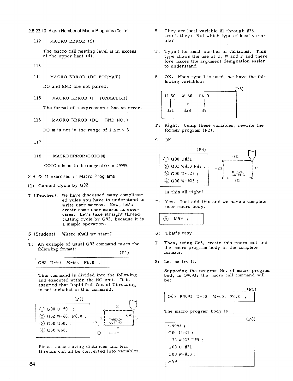
2.8.23.10 Alarm Number of Macro Programs (Cent’d)
112
MACRO ERROR (5)
s: They are local variable #1 through #33,
aren’t they ? But which type of local varia–
ble ?
The macro call nesting level is in excess
of the upper limit (4) .
113
114 MACRO ERROR (DO FORMAT)
DO and END are not paired.
115 MACRO ERROR ([ ] UNMATCH)
The format of < expression > has an error.
116
117
118
2.8.23.11 Exercises of Macro Programs
(1) Canned Cycle by G92
T (Teacher) : We have discussed many complicat-
MACRO ERROR (DO - END NO. )
DO m is not in the range of 1 <m< 3.
MACRO ERROR (G~O N)
GOTO n is not in the range of O < n <9999.
ed rules you have to understand to
write user macros.
create some user macros as exer–
cises. Let’s take straight thread-
cutting cycle by G92, because it is
a simple operation.
Now, let’s
T: Type I for small number of variables. This
type allows the use of U, W and F and therefore makes the argument designation easier
to understand.
S: OK. When type I is used, we have the fol-
lowing variables:
(P3)
m
T: Right. Using these variables, rewrite the
fo;mer progr-m (P2)
S: OK.
(P4)
#21I
r
m
–#23
—————
J?
/#21
#~3
@ GOO U#21 ;
@ G32 w#23 F#9 ;
@ GOO U-#21 ;
@ GOO w-#23 ;
n
Is this all right?
T:
Yes. Just add this and we have a complete
user macro body.
I 1
l@ M99;
I
S (Student) : Where shall we start?
T: An example of usual G92 command takes the
following format:
G92 u-50. w-60. F6. O :
This command is divided into the following
and executed within the NC unit. It is
assumed that Rapid Pull Out of Threading
is not included in this command.
First, these moving distances and lead
threads can allbe converted into variables.
(Pi)
84
That’s easy.
s:
Then, using G65,
T:
the macro program body in the complete
formats.
Let me try it.
s:
Supposing the program No. of macro program
body is 09093; the macro call command will
be:
G65 P9093 u-5o. w-6o. F6. O ;
The macro program body is:
—- —-—
I 09093 i
GOO U#21 ;
I
I G32 w#23 F#9 ;
I GOO U-#21
GOO w-#23 ;
M99 ;
create this macro call and
(P5)
(P6)
Page 93
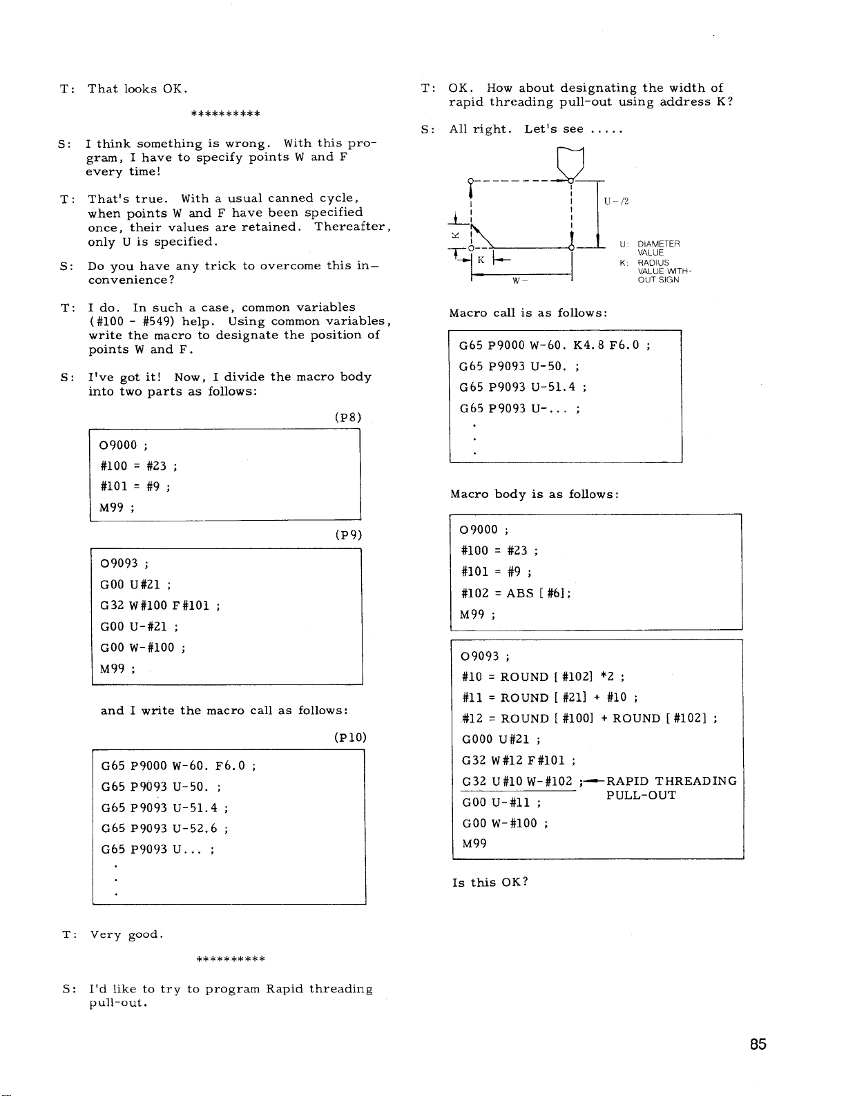
T:
That looks OK.
**********
I think something is wrong. With this pro-
s:
gram, I have to specify points W and F
every time!
That’s true. With a usual canned cycle,
T:
when points W and F have been specified
once, their values are retained. Thereafter,
only U is specified.
Do you have any trick to overcome this in–
s:
convenience ?
I do. In such a case, common variables
T:
(#loo - #549) help.
write the macro to designate the position of
points W and F.
s:
I’ve got it! Now, I divide the macro body
into two parts as follows:
09000 ;
#100 = #23 ;
#lol = #9 ;
M99 ;
09093 ;
GOO U#Zl ;
G32 W#100 F#lOl ;
GOO U-#21 ;
GOO w-#100 ;
M99 ;
and I write the macro call as follows:
G65 P9000 w-60. F6. O ;
G65 P9093 u-50. ;
G65 P9093 u-51.4 ;
G65 P9093 u-52.6 ;
G65 P9093 U. . . ;
Using common variables,
(P8)
(P9)
(Plo)
T: OK.
s:
How about designating the width of
rapid threading pull–out using address K ?
All right. Let’s see .....
1--1
-—....———
J/
T
U DIAMETER
VALUE
K RADIUS
VALUE WITH
OUT SIGN
Macro call is as follows:
G65 P9000 w-60. K4.8 F6. O ;
G65 P9093 u-50. ;
G65 P9093 u-51.4 ;
G65 P9093 U-. . . ;
Macro body is as follows:
09000 ;
#100 = #23 ;
#lol = #9 ;
❑ ABS [ #6];
#102
M99 ;
09093 ;
#10 = ROUND [ #102] *2 ;
#11 = ROUND [ #211 + #10 ;
#12 = ROUND [ #100] + ROUND [ #102] ;
GOOO U#21 ;
G32 W#12 F#lOl ;
G32 U#10 W-#102 ;—RAPID THREADING
GOO U-#11 ;
GOO w-#100 ;
M99
PULL-OUT
T:
Very good.
**********
I’d like to try to program Rapid threading
s:
pull-out.
Is this OK?
85
Page 94

2.8.23.11 Exercises of Macro Programs (Cent’d)
T:
Yes.
Your reasoning is right. Practically,
you had better prevent a malfunction by
programming #3003: invalid control of single
block or #3004: invalid control of feedhold.
This threadcutting can be performed in Uand W-directions only. Now we’d like to
expand this function in four directions.
ii
S: I see.
-----
L
~___-__q++ ME:
K--L--J
Let me think.
--- How about the next program ?
w
TH READ
K
CUTTING
y
;=
i----------- ‘—
G 00
( F)
T
u/2
h
09093:
#3003 = 1 ;
_ Single block invalid
M93 ; _ 4-block buffering
#10 = ROUND [#102] *2 ;
IF [ABS] [#21] LT #10] GOTO 4 ;
IF [#21 GTO] GOTO 1 ;
IF [#21 EQ O] GOTO 4 ;
#11 =ROUND [#21] + #lO; _ U : Negative
#12= #lo;
GOTO 2 ;
N1 #ll=ROUND[#21] -#11 ;
_ U : Positive
#12= –#lo;
N2 #13= ROUND [#102] ;
IF [ABS [#100] LT #13] GOTO 4 ;
IF [#100 GTO] GOTO 3 ;
IF [#100 EQ O]GOTO 4 ;
#14 = ROUND [#100] + #13 ; _ W: Negative
#15= –#13:
G0T05;
N3 #14 = ROUND [#100] - #13; -W: Positive
#15= #13
U, K:
Designation with a sign
K: Designation without a sign
u = #21 (DIAMETER vALuE)
W = #23
K = #6 (RADIUS VALuE)
F=#9
The macro call command is as follows:
G65 P9000 W-45. K4. O F5.0 ;
G65 P9093 u40. ;
G65 P9093 u41.4 ;
G65 P9093 U.. . ;
The macro program body is as follows:
09000 ;
#100 = #23 ;
—w
#lol = #9 ;
#102 = ABS [#6] ;—
I:\
M99 ;
GOT05;
N4 #3000= 499 (MACRO INPUT ERR.) :
~ Error display
N5 GOOU#21 ;
#3004 = 7 ;
f~~fmidejhwilid
G32 W##14F#lOl :
G32 U#12 W#15 ; fl~-~ulg
#3004 = o ;
GOOU-ttll ;
GOOW-#lOO;
M92 ;
#3003 = o ;
M99 ;
Well. If Uor W= O,andl U/210rl W I<K,
error willbe displayed in your programming.
That’s good.
86
Page 95

2.8.24 PROGRAM MIRROR IMAGE (G 68, G 69)+
Program mirror image is the feature to reverse
the NC program operation in all directions
around the work center line (Z–axis) by the use
of G command.
(1)
G68; . . .
Program mirror image on.
The program mirror image on
state is held until G69 is speci–
fied.
G69; . . .
Program mirror image off.
The program mirror- image off
state is held until G68 is specified.
When program mirror image is on, the Xaxis operation by the NC program is in–
verted with Z-axis being the center line.
The manual operations (manual continuous
feed and handle /step feed) are not affected
by this feature.
(2)
Details of program mirror image
When the PROGRAM mirror image feature is
on,
the movement by the NC program is
inverted with Z-axis being the center line.
The following inversion is processed in the
NC unit:
X command for X-axis
a.
coordinate value is
inverted.
U command for X-axis
b.
incremental coordinate
value is inverted.
I command for X ‘axis
c,
coordinate value of
arc center is inverted.
d.
Circular motion direction inverted.
+x
L,, -
VIRTUAL TOOL NOS?’
VIRTUAL TOOL NOSE
a
(3)
Cautions for G68 and G69 commands
a.
G68 and G69 are modal G commands which
~.
~., “
/-<02’,
~ CENTER \
b
L.+.””
TOOL
CENTER
Fig. 2.40
Programmed tool
radius compensation
Tool center
;
T + ::;.1 ;: ;
Virtual tool nose
G 41
—+Z
Compensation T-: I:. X.”: :
and tool center
G44 when PROGRAM
.
mirror Image function
is on
belong to “ 10” group. They must be speci-
fied on a single block basis, in principle.
b.
G69 (program mirror image off) is used at
the time of power–on, reset operation, and
program reset.
c,
These commands must be specified in the
tool nose radius compensation cancelled
state.
These commands may not be specified in the
da
finishing shape program of the special canned
cycle.
e.
If automatic origin return “G28 X. . . Z. . . ;”
is specified when the X-axis mirror image
feature is on, the positioning of the inter-
mediate point specified in X and Z is affect-
ed by the mirror image, but the machine
origin, which is an absolute position, is not
affected by this feature.
+x
~ PROGRAMMED CIRCULAR ARC
DIRECTION OF ROTATION
G 02”.,
\
--
CHANGED
TO G 03
CIRCULAR ARC ROTATIONAL
DIRECTION OF RoTATION
WITH PROGRAM MIRROR IMAGE
(
FEATURE ON
Fig. 2.39
I command for X-axis beveling /rounding
e.
volume and direction is inverted.
I command for canned cycle taper X-axis
f.
distance is inverted.
U and I commands for special canned cycles
g.
finishing allowance, etc. are inverted.
The operational direction after X–axis tool
h.
position compensation is inverted.
T command for tool nose radius compensa–
i.
tion tool nose center is inverted in the sign.
G command for tool nose radius compensa-
j.
tion virtual tool nose position is inverted.
+x
1
G28X...;...;
,-----\
,/
//
/’
PROGRAMMED iNTER-
,/
MEDIATE POINT
INTERMEDIATE POINT PRODUCED
BY X-AXIS MIRROR IMAGE FEATURE
*----- --
7
Fig. 2.41
I’_
/
ASSOLUTE
ZERO
POINT
EXAMPLE :
Described below is a sample program which
uses G68 and G69 for the opposed tool rest
shown in the diagram on the following page,
and the X–axis movements.
+Z
87
Page 96

2.8.24 PROGRAM MIRROR IMAGE (G68, G69) “t (Cent’d)
2,8.25 MULTIPLE REPETITIVE CYCLES(G70 TOG76)+
Power on
+
Manual reference point return
+
Program execution
NOOO1 G50 x240. z220. ;—240.000
NOO02 X40. Z120. TO1O1 ;—96.000
NOO03G68 ;
NOO04G50U480. ;
NOO05 x80. z80. Tllll ;—+144.000
NOO06G69 ;
NOO07 G50 u480.;
NO008 X120. z40. TO1O1 ;—176.000
+x
~-$
I
F
-96.000
+384.000
-144.000
336.000
220
U-144.000
u240.000
u-160.000
OFFSETO1 ;~
A TURRET
T01
-48
F
2,8.25.1 General
This option makes program simple and short.
For instance, both stock removal and finishing
are performed only by commanding the finish–
ing work shape.
Table 2.21 Multiple Repetitive Cycles
G code
G 70 Finishingcycle
G71
G 72
G 73 Pattern repeating
G 74
G 75
G 76 Automatic thresdcutting
(1) G70 through G76 are in * group and non-
(2) The program of finishing shape specified
l--
.
:--
-1
—+Z
.%ckremovai in turning
Sto6k removal in facing
Peck drilling in Z axis
Grcmvingin X axis
modal.
by G71, G72 and G73 are stored in memory.
The memory capacity for the finishing shape
is 45 blocks.
Program of finishing shape <45 blocks
I
Note: When cornering (G 11, G 12) and
multiple cornering (G 111, G 112) are used,
each block containing them must be count-
ed as the value listed below.
Name
Finishing
by G 70
possible
Tip nose radius ceinpensation
impossible.
Remarks
Tip nose radius
compensation
possible
88
TURRET
B
OFFSET 11 X84
Z8
-1-
No, of blocks
One block including G
.&
s
(3) The internal memory for storing the finish-
orG12
One block including G 111
One block including G
ing shape program :
To shorten the stock removal cycle computation time, the finishing shape program is
binary-converted and then is stored in the
memory for storing finished shape program
(one pair) in the unit. This memory is
called the internal memory for finishing
shape program, which differs from the part
program memory.
II
IIZ
bkxks
TWO
Four blocks
Five
blocks
Page 97

(4) In the block after the cycle of G70 through
G76, the G codes of 01 group should be
specified again. This is because the 01group G codes specified before the cycle
may have been changed to other G codes
by the execution of this cycle.
(5) It is possible to perform tool nose radius
compensation on the cycle of G 70 through
G73.
(6) Tool nose radius compensation cannot be
performed on the cycle of G74 through G76.
Any attempt to do so will result in an error.
Sequence number for cycle start
Sequence number for cycle finish
I
G71 Pns
Qnf Uf. . .
—
—
—
-
2.8,25.2 Stock Removal in Turning (G 71)
Stock removal in turning with the finishing allow-
ance remained uncut can be commanded by G71.
Commands for finished contour are different between monotonous increase /decrease and concaved shaped path.
(1) Monotonous increase /decrease finishing
shape
Ki. ..
. . .
D
F(E). . . S.. . :
Feedrate and spindle-speed
designation for stock removal
in turning
Nns .. ... ;
.....
. . . . .
F
. . . . .
s
. . . . .
Nnf . . . . . ;
Finishing shape program (45 blocks maximum)
Tool nath:
Sequ&nce number should start with ns and end with nf.
F and S commands are effective only when G70 finishing
cycle is executed.
+x
FINISHING
ING ALLOWANCE
;
;
;
(Retracting) c
1A
Rough
1
Rough finishing allowance in X-axis direction
(radius designation)
Finishing allowance in the
direction of Z-axis
Finishing allowance in the direction of
X-axis (diameter designation)
A+Af+B
G71 starts at point A, executes rough
finish
cycle (––-) , and returns to point A to be
terminated.
Start and flmsh
at poslt!on A
7 _____
+Z
Flmshlng shape
program
Stock removal
cycle
Rough flmshlng
cycle
designation) , the rough finishing cycle is
omitted.
De~th of cut in X–axis direction
(d&ignation without signs)
finishing allowance in Z-axis direction
Note: Feed command F(E)
and spindle command (s)”
are given for executing
stoc~ removal cycle. -
cycle (—) and the rough finishing
In the case of I = O and K = O (or no
Fig. 2.42
89
Page 98

25.2 Stock Removal in Turning (G
2.8.
71) (Cent’d)
(2) Concaved finishing contour (Type B)
+x
B
FINISHING
ALLOWANCE
Q
Retracting is
GOO. Thrust
(GOO or GO1)
AA’.
Each depth of cut D along X-axis can
be overrided by 10%step within the range
of O to 200%, by G71/G72 cut depth override selection or setting.
Notes :
1.
The tool path of finishing shape should be
programmed to be monotonous increase or
decrease in X and Z coordinates.
(Retracting)
c
A
D
1
x
1;
A’
Fig. 2.43
performed by rapid traverse
motion depends on the speed
specified by the program of
See item (3) , g.
a. Command format
ns:Sequencenumberforcyclestart
~ .,:Sequencenumberforcyclefinish
r
G71 Pns Qmf Uf... 1!... D... F(E)... S... &
Nuns.,.......;
. .. F. ..... ;
..........
s
............. .
.............
Nnf......... ;J l,_...
Note 1:
and spindle command (S ) for the execution
of stock removal cycle.
Note Z:
concaved finishing shape program if R1 is
specified.
\
;h1
Specifies the feed command (F(E) )
ComDutes the cutting ~ath for the
——- .—. -—— —.
TTT
1 II
L
RoughfinishingallowanceinX-axis
direction(radiusdesignation)
Finishingallowanceinthedirectionof
X-axis(diameterdesignation)
Fnnshmgshapeprogram(45blocksmaximum)
Two]path:A + A’+ B
(Retracting)
____ ____ -..
Note1 Note2
L
D.+thofcutin~-a~is~i~ectra~
(designationwithoutsigns)
-.
.-
POSITION
SHIFTED
FROM POINT
The following should be taken into consider-
2.
ation in programming the start block ( Nns)
and the end block (Nnf) of a finishing shape
program.
X MONOTONOUS
INCREASE
+x
I
I
X
~p+,q:,
A’<
A<
-!T_____
MONOTONOUS
INCREASE
------4--
A’
4
+x
FINISHING ALLOWANCE
I
+----+z
G71 starts at point A, executes the rough
cutting cycle (—
cycle ( ––– ) , and returns to point A to be
terminated.
finishing cycle is skipped.
Retracting is performed by rapid traverse
GOO. Thrust motion depends on the speed
(G 00 or GO1) specified by the program of
AA’.
can be overrided by 10% step within the
range of O to 200%, by G711G72 cut depth
override selection or setting. See item ( 3) ,
b. Cautions for concaved finishing shape pro-
gram
(i) Rough cutting cycle by G71 starts from
Each depth of cut D along X-axis
the closest concave to the start point.
— PROG RAM
— STOCK REMOVAL CYCLE
““””””””””””ROUGH FINISHING CYCLE
) and the rough finishing
If I is not specified, the rough
FINISHING
FINISHING SHAPE
90
Nnf
IS’INPARALLEL WITH Z AXIS
I
BA
+Z
Page 99

COMMAND POINT
OFFINALBLCCK
W FINISHING
SHAPEPR03RAM
‘YmkNG
(ii)
Since cutting starts with the concave
nearest the start point, the cutting path
is interrupted if it hits the convex beyond the concave. The concave is cut to
its bottom. Then, the cutting cycle returns to the interrupted point to perform
cutting beyond it.
DISCONTINUATION
DEPTH OF
CUT D
U 50 NTlNuED
For a simple concave, only one interrupted
point is provided. However, for a complex
concave containing a smaller concave and
a convex as shown below, the cutting path
is interrupted first at the larger convex
then at the smaller convex.
POINT
Any contour having an overhang does not
(iii)
allow cutting.
cation value of the finishing shape program
should be a monotonous variation.
(iv)
The termination block for the finishing shape
program has the following limitations:
For the G command of the termination block
(Nnf. . .
pal.
(v)
The retracting amount after each approach
cycle may be set by the setting.
\
\
\r
Hence, the Z-axis specifi-
; ) , specify GO1 or GOO., in princi-
RETRACTING AMOUNT SETTING
if62D2 (FOR G 71)
---- ---
CUTTING PATH
‘\
\
DISCONTINUATION 1
‘hTA
co”c’v’ \ /
The maximum number of interrupted
points that,allows cutting is three, beyond which cutting is disabled, causing
“09711error.
number of concaves is allowed.
B
Within this limitation, any
DISCONTINUATION 1
L4K
CONCAVE
(vi)
Each block of the finishing shape program
should be of monotonous increase or monotonous decrease. A circular arc which
extends over two or more quadrants must
be divided into two blocks before being
programmed.
Generally, Z-axis finishing allowances W
(vii)
and K are not specified. Otherwise, a bite
is caused into the wall of the corresponding
side.
tional monotonous increase /monotonous decrease stock removal cycle is provided.
(viii)
Approach is performed at the feedrate.
It is not affected by the G code of the
finishing shape program. Hence, depending on the finishing shape program,
positioning may be performed by rapid
traverse after the approach at feedrat e.
A
If “R 1“ is not specified, the conven-
A
APPROACH
3
Sample Contour Not A1lowing Cutting
91
Page 100
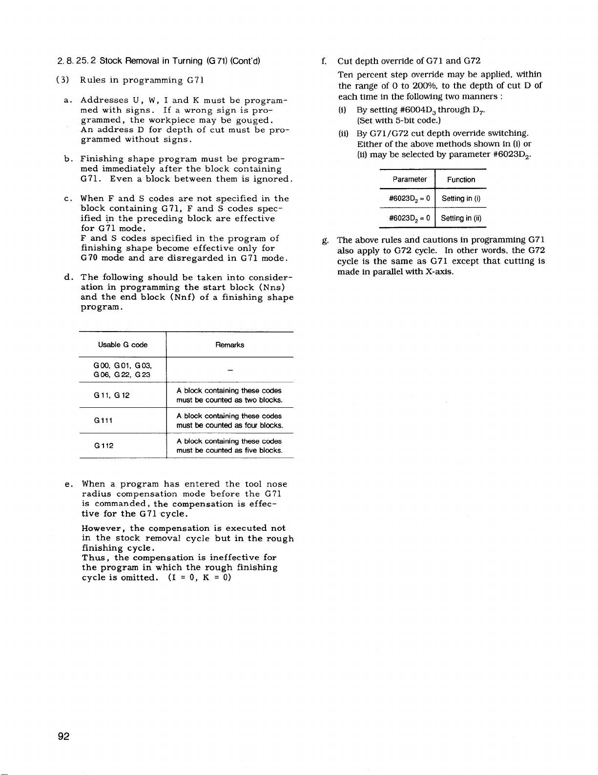
2,8.25.2 Stock Removal in Turning (G 71)(Cent’d)
(3)
Rules in programming G71
Addresses U, W, I and K must be program-
a.
med with signs. If a wrong sign is programmed, the workpiece may be gouged.
An address D for depth of cut must be programmed without signs.
Finishing shape program must be program-
b.
med immediately after the block containing
G71. Even a block between them is ignored.
c.
When F and S codes are not specified in the
block containing G71, F and S codes specified in the preceding block are effective
for G71 mode.
F and S codes specified in the program of
finishing shape become effective only for
G70 mode and are disregarded in G71 mode,
The following should be taken into consider-
d.
ation in programming the start block ( Nns )
and the end block (Nnf) of a finishing shape
program.
f. Cut depth override of G71 and G72
Ten percent step override may be applied, within
the range of O to 200V0, to the depth of cut D of
each time in the following two manners :
(i)
By setting ##6004D3through D7.
(Set with 5-bit code.)
(ii)
By G71 /G72 cut depth override switching.
Either of the above methods shown in (i) or
(ii) may be selected by parameter #6023D2.
g. The above rules and cautions in programming G71
also apply to G72 cycle.
In other words, the G72
cycle is the same as G71 except that cutting is
made in parallel with X-axis.
Usable G code
GOO, GO1, G03,
G06, G22, G23
Gil, G12
Gill
G112
When a program has entered the tool nose
e.
A block containing these codes
must be counted se two blocks.
A block containing these codes
must be counted as four blocks.
A block containing these codes
must be counted as five blcxks.
Remarks
—
radius compensation mode before the G71
is commanded, the compensation is effec–
tive for the G71 cycle.
However, the compensation is executed not
in the stock removal cycle but in the rough
finishing cycle.
Thus, the compensation is ineffective for
the program in which the rough finishing
cycle is omitted. (I = O, K = O)
 Loading...