

Page 1
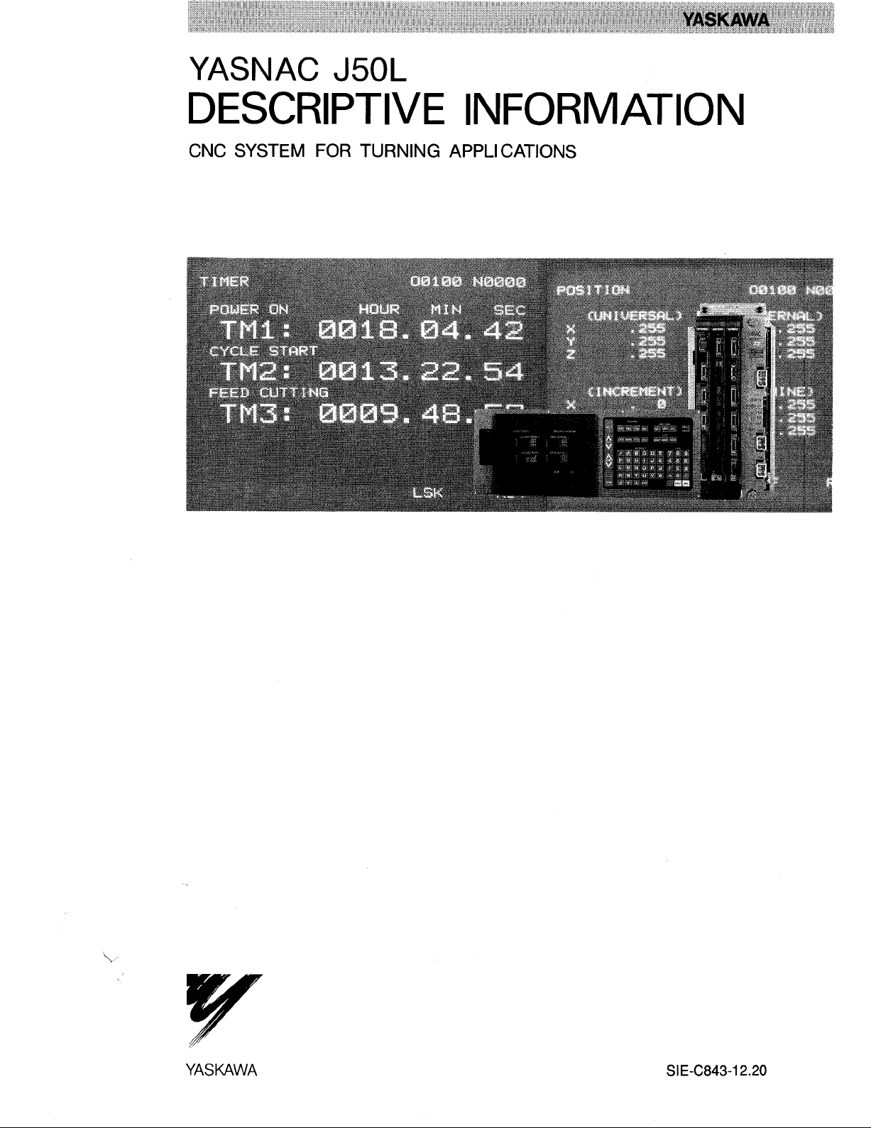
YASNAC J50L
DESCRIPTIVE INFORMATION
CNC SYSTEM FOR TURNING APPLI CATIONS
\
Y
YASUAWA
SIE-C843-12.20
Page 2
1 INTRODUCTION
The YASNAC J50L is a high-performance CNC for the simultaneous control of
2 or 3 axes of a lathe machining tools, with emphasis placed on high-speed
machining, and programming capability.
FEATURES
1.
Ultra-high-speed Performance
“High-speed, computing system” is achieved by installing a 32-bit microprocessor in the YASNAC J50L.
Significant Downsizing (miniaturized)
2.
YASNAC J50L is significantly downsized because it has surface mounted
devices and customized gate arrays.
This manual explains both basic and optional features of
YASNAC J50L as
well as the servo system.
You can determine your own hardware requirements after carefully reading
this manual.
This manual is subject to change without
notification due to product improvements,
model changes, etc.
Page 3
CONTENTS
f INTRODUCTION i
2 BASIC FEATURES
2.1 CONTROLLED AXES 1
2.2 SIMULTANEOUS
CONTROLLABLE AXES 1
2.3 LEAST INPUT INCREMENT 1
2.4 LEAST OUTPUT INCREMENT 1
1
2.5 MAXIMUM PROGRAMMABLE DIMENSIONS 1
2.6 TAPE CODE i
2.7 EIAo 1S0 AUTO-RECOGNITION 1
2.8 TAPE FORMAT 1
2.9 DECIMAL POINT PROGRAMMING 1
2.10 BUFFER REGISTER 1
2.11 RAPID TRAVERSE RATE AND FEEDRATE 2
2.12 FEED FUNCTION (F-, E-FUNCTION) 2
2.13 AUTOMATIC
ACCELERATION/DECELERATION 2
2.14 FEEDRATE OVERRIDE AND
FEEDRATE OVERRIDE CANCEL 2
2.15 PREPARATORY FUNCTION
(G-FUNCTION) 3
2.16 ABSOLUTE/INCREMENTAL
PROGRAMMING (G90/G91) 3
2.17 PROGRAMMING OF
ABSOLUTE ZERO POINT (G50) 3
2.18 POSITIONING (GOO) 3
2.19 POSITIONING IN ERROR
DETECT OFF MODE (G06) 3
2.20 LINEAR INTERPOLATION (GO1) 3
2.21 CIRCULAR INTERPOLATION (G02, G03) 4
2.22 DWELL (G04) 4
2.23 REFERENCE POINT RETURN CHECK (G27) 4
2.24 AUTOMATIC RETURN TO
REFERENCE POINT (G28) 4
2.25 RETURN FROM REFERENCE POINT (G29) 4
2.26 MULTI-START THREADCUTTING (G32) 5
2.27 CANNED CYCLES (G90, G92, G94) 5
2.28 FEED FUNCTION DESIGNATION
(G98, G99) 6
SPECIAL G-CODE I 6
2.29
2.30 MISCELLANEOUS FUNCTION
(M-FUNCTION) 6
2.31 SPINDLE-SPEED FUNCTION
(S-FUNCTION) 7
2.32 TOOL FUNCTION (T-FUNCTION) 7
2.33 TOOL POSITION OFFSET 7
2.34 BACKLASH COMPENSATION 7
2.35 MANUAL FEED 7
2.36 MANUAL RETURN TO REFERENCE POINT 7
2.37 BUILT-IN TYPE NC OPERATOR’S STATION 7
2.38 PART PROGRAM STORAGE AND EDITING 8
2.39 SUBROUTINE PROGRAM (M98, M99) 8
2.40 PARAMETER STORAGE 8
2.41 SETTING FUNCTION 8
2.42 INTERNAL DATA TAPE INPUT 8
2.43 OPERATION TIME DISPLAY 8
2.44 ADDRESS SEARCH 9
2.45 PROGRAM NUMBER 9
2.46 LABEL SKIP 9
2.47 CONTROL IN/OUT 9
2.48 SINGLE BLOCK 9
2.49 OPTIONAL BLOCK SKIP 9
2.50 DRY RUN 9
2.51 MACHINE LOCK AND DISPLAY LOCK 9
2.52 AUXILIARY FUNCTION LOCK 9
2.53 MANUAL ABSOLUTE ON/OFF 9
2.54 EDIT LOCK 10
2.55 INTERLOCK 10
2.56 RAPID PULL OUT OF THREADING 10
2.57 ERROR DETECT 10
2.58 DOOR INTERLOCK 10
2.59 FEED HOLD 10
2.60 EMERGENCY STOP 10
2.61 OVERTRAVEL 10
2.62 REMOTE RESET 10
2.63 REMOTE POWER ON/OFF 10
2.64 MACHINE READY INPUT SIGNAL 10
2.65 CONTROL POWER ON OUTPUT SIGNAL 10
2.66 SERVO POWER ON OUTPUT SIGNAL 10
2.67 TOOL MOVE OUTPUT SIGNAL AND
THREAD CUTTING OUTPUT SIGNAL 10
2.68 NC ALARM OUTPUT SIGNAL 10
2.69 INPUT ERROR OUTPUT SIGNAL 11
2.70 NC RESET OUTPUT SIGNAL 11
2.71 EXTERNAL ERROR INPUT SIGNAL 11
2.72 RS-232C INTERFACE PORT 11
2.73 ON-LINE DIAGNOSTICS 11
2.74 POSITION DETECTOR INTERFACE 11
2.75 INPUT/OUTPUT CONNECTORS 11
2.76 POWER INPUT 11
2.77 AMBIENT CONDITIONS 11
2.78 SPINDLE PULSE GENERATOR 12
Page 4
CONTENTS (Cent’d)
3 BASIC OPTIONS 72
AC SERVO CONTROL UNITS 12
3.1
3.2 AC SERVOMOTORS 12
OPTIONS 13
4
SEPARATE TYPE NC OPERATORS
4.1
STATION 13
4,2 SEPARATE TYPE TAPE READER 13
4.3 TAPE READER WITH REELS 13
4.4 M3-DIGIT BCD OUTPUT 13
4.5 ADDITIONAL TOOL OFFSET MEMORY
4.6 ADDITIONAL PART PROGRAM STORAGE 13
4.7 ADDITIONAL PROGRAM NUMBER
REGISTRATION 13
13
4.8 OPERATION TIME DISPLAY B 14
4.9 STEP-MODE SIMULTANEOUS
ONE-AXIS OPERATION 14
4.10 INTERNAL TOGGLE SWITCHES 14
4.11 G50 POINT RETURN 14
4.12 RESTART AFTER MANUAL
INTERRUPTION 14
4.13 PROGRAM RESTART 15
4.14 EXTERNAL INPUT, COLLATION,
AND OUTPUT 15
4.15 BUFFERING FUNCTION (M92, M93) 15
4.16 INCH/METRIC SETTING 15
4.17 RADIUS PROGRAMMING FOR
CIRCULAR INTERPOLATION (G22, G23) 15
4.18 ANGLE PROGRAMMING FOR LINEAR
INTERPOLATION (GO1) 15
4.19 TOOL OFFSET VALUE SETTING (G 10) 16
4.20 CORNERING (Gil, G12) 16
4.21 MULTIPLE CORNERING
(BEVELING/ROUNDING) (Gl 11, G1 12) 16
4.22 MULTI-START THREADCUTTING (G32) 18
4.23 VARIABLE LEAD THREADCUTTING (G34) 18
4.24 2ND REFERENCE POINT RETURN (G30) 18
4.25 TOOL NOSE RADIUS COMPENSATION
(G40 TO G44) 19
4.26 MULTIPLE REPETITIVE CYCLE
(G70 TO G76) 19
4.27 THREADCUTTING INTERRUPTION 23
4.28 CONSTANT SURFACE SPEED CONTROL
(G96, G97) 23
4.29 SPINDLE-SPEED OVERRIDE 23
4.30 SPECIAL G-CODE 11 23
4.31 OPTIONAL BLOCK SKIP B (/2 TO /9) 23
4.32 X-AXIS MIRROR IMAGE 23
4.33 AUTOMATIC COORDINATE SYSTEM
SETTING 24
4.34 WORK COORDINATE MULTI-SHIFT
(G50T) 24
4.35 MDI OF MEASURED WORK INPUT 24
4.36 WORK COORDINATE SYSTEM SHIFT 25
4.37 EXTERNAL WORK NUMBER SEARCH A 25
4.38 EXTERNAL DATA INPUT 25
4.39 SPINDLE INDEXING 25
4.40 STORED STROKE LIMIT (G36 TO G39) 25
4.41 STORED STROKE LIMIT FOR
EACH TOOL 26
4.42 SKIP FUNCTION (G31) 26
4.43 TOOL LIFE CONTROL (G122, G123) 26
4.44 MACRO PROGRAMS (G65, G66, G67) 27
4.45 STORED LEADSCREW ERROR
COMPENSATION 28
BUILT-IN TYPE PROGRAMMABLE
5
CONTROLLER (PC) 28
APPENDIX 1 LIST OF DATA 29
APPENDIX 2 DIMENSIONS in mm (inch) 36
...
111
Page 5
INDEX
Subject
A ABSOLUTE/INCREMENTAL PROGRAMMING (G90/G91) o . . . . . . . 2 . . . . ~ 2.16 “ . “ “ 3
AC SERVO CONTROL UNITS. ..”” $”””””””””””””””” ““”3””””” 3.1 ““””12
AC SERVOMOTORS . . . . . . . . . . . . . . . ...””.””-””. .“””3””” .3.2 ““””12
ADDITIONAL PART PROGRAM STORAGE ........””.”.$””4””” ““4.6 ““””13
ADDITIONAL PROGRAM NUMBER REGISTRATION . . . 0 . . . . . . . 4 $ . “ . “ 4.7 “ “ “ “ 13
ADDITIONAL TOOL OFFSET MEMORY . . . . ...”””””””””””” 4“””””
ADDRESS .SEARCH . . . . . . . . . .,,.,..........’””” ““”2””’”
AMBIENT CONDITIONS . . . . . . . . . ...’......’.’”” ““”””2”””””
ANGLE PROGRAMMING FOR LINEAR INTERPOLATION (GO1) . . . . 4 . . . - .
AUTOMATIC ACCELERATION/DECELERATION . . . . . . 0 . . . . . “ 2 “ “ “ “ “
AUTOMATIC COORDINATE SYSTEM SETTING . . . . . . . . . . . 4 “ “ “ “ “
AUTOMATIC RETURN TO REFERENCE POINT (G28) . 0 - . . . . . . . . 2 . “ “ “ “
AUXILIARY FUNCTION LOCK. . . ...””””””’””””””””” ““”2”””””
B BACKLASH COMPENSATION ............”..””””” ““2”””””
BASIC FEATURES . . . . . . . . . . . . . . . . . . . . ..”. ..” O” “’”24”””’
BASIC OPTIONS . . . . . . . . . . . . . . . . . . . . .“”””””””””” 3”””””
BUFFER REGISTER . . . . . . . . . . . . . . . . . . . . . . . . . . . . . . .2 ..”””
BUFFERING FUNCTION (M92, M93) .....003.””””.”..-OC”4 ““”.”
BUILT-IN TYPE PROGRAMMABLE CONTROLLER (PC) . . . . . . ~ . . . 5 . . . . .
BUILT-IN TYPE NC OPERATOR’S STATION.”<”.”.””-”O”” “’” 2“””””
C CANNED CYCLES (G90, G92, G94) ““”””””””””””””””””2 ““”
CIRCULAR INTERPOLATION (G02, G03) ..........”.””” 2“”.”.
CONSTANT SURFACE SPEED CONTROL (G96, G97) . . . . . . . . . . 4 ‘ . “ “ “
CONTROL IN/OUT”-””””””” ““.”””””””””””””””””” “2”””””
CONTROL POWER ON OUTPUT SIGNAL . . ..-- ””’” ””. ”””” O” 2“””””
CONTROLLED AXES”””””””” ““”””””””””””””””””””” “2”””””
CORNERING (G1l, G12) ...””” ““”””’””””””””””””””””4 ““”””
D DECIMAL POINT PROGRAMMING “.”” ”””” ”””’ ”””” ”’””””2 ““”””
DIMENSIONS inmm [inch)””” ““””””””””””””””””” Appendix”””
DOOR INTERLOCK . . . . . . . . . . . . . . . . ...””””””””” ““”2”””””
DRY RUN....””””””””” ““”-’”””””’”””””””””” ““”2””””’
DWELL (G04) ””””””””””””” ““””””””””””””””””””””2 ““”””
E EDIT LOCK . . . . . . . . . . . . . ......””’””””oo’o”””” “2””’””
EIA. ISO AUTO-RECOGNITION . ..”””””’””””””””””” ““””2”””””
EMERGENCY STOP . . . ...””””””.”.””” ““”””””””””””2””” ““
ERRORDETECT . . . . . . . . . . . ...”-”””””’”” ““””-””””2”””””
EXTERNAL DATAINPUT” ““”””””””””””””””” ““”””””””4”””””
EXTERNAL ERRORINPUTSIGNAL .“”o..”””--C”””..”” ‘“”2”””””
EXTERNAL INPUT, COLLATION, AND OUTPUT . 0 “ “ “ “ “ “ “ “ o “ “ “ 4 “ “ “ “ “
EXTERNALWORK NUMBER SEARCH””””””””.+” ““””””””4”””””
F FEED FUNCTION (F-, E-FUNCTION) . . . .. ”” ””” O””””””’”” “2””’””
FEED FUNCTION DESIGNATION (G98, G99) “ “ “ “ “ “ “ “ “ “ “ “ “ “ “ 2 “ “ “ “ “
FEED HOLD . . . . . . . . . ..””””””””””””””” ““”””””””2”””””
FEEDRATE OVERRIDE AND FEEDRATE OVERRIDE CANCEL . . . “ “ 2 “ “ “ “ “
G G50 POINTRETURN ”.”””” ““.””””””””.””””.”” .“””” 4”.”””
I INCH/METRICSETTING.. . .<..””.””””’”””””’ ‘“”””””4’””””
INPUT ERROROUTPUTSIGNAL . .””””””’””””””””” ““””””2’””””
INPUT/OUTPUTCONNECTORS . . . . ...””””””””””” ““””””2”””””
INTERLOCK .O. .O..”oo ‘--..””””’””””””””” ““”””””2””’”’
INTERNAL DATATAPEINPUT ““””””””-”o”””””””” ““””””2”””””
INTERNALTOGGLE SWITCHES . . . . . . . . ...””””””” ““””””4”””””
INTRODUCTION . . . . . . . . . . . . . . . . . . . . . . . .. ”””” ”””” 1”””” ““
Chapter
Section Page
4.5 . ...13
2.44 .,,.9
2.77....11
4.18....15
2.13 ...2
4.33....24
2.24 .,..4
2.52 . ...9
2.34... 7
. . . . . . . .
. . . . . . . .
2.10 . . . . 1
4.15....15
. . . . . . .
2.37 ..,.7
2.27 . . . . 5
2.21 . ...4
4.28....23
2.47 . ...9
2.65....10
2.1 . ..1
4.20....16
2.9 . ...1
. . . . . . . .
2.58....10
2.50 . ...9
2.22 . ...4
2.54.,..10
2.7 . . . . 1
2.60....10
2.57....10
4.38....25
2.71....11
4.14 ..””15
4,37....25
2.12 . . . . 2
2.28 . ...6
2.59....10
2.14 ...2
4.11...14
4.16....15
2.69....11
2.75....11
2.55 ”.”=10
2,42 . ...8
4.10....14
. . . . . . . .
. 28
.36
1
12
i
iv
Page 6
INDEX (Cent’d)
Subject Chapter
L LABEL SKIP . . . . . . . . . . . . . . . . . . . . . . . . . . . . . . . . . . . . 2 . . . . . 2.46....9
LEAST INPUTINCREMENT ..c............... . . . . . . ...2.....2.3 . . ..I
LEAST OUTPUTINCREMENT . . . . . . . . . . . . . . . . . . . . . . ...2.....2.4 . ...1
LINEAR INTERPOLATION (GO.l) . . . . . . . . . . . . . . . . . . . . . ...2.....2.20.. ..3
LIST OF DATA . . . . . . . . . .:, . . . . . . . . . . . . . . . . . . . ..APPENDIx I.... . . . ...29
MMACHINE LOCKAND DISPLAY LOCK . . . . . . . . . . . . . . . . . ..2. ..”. .2.51. . ..9
MACHINE READYINPUTSIGNAL . . . . . . . . . . . . . . . . . . . . ...2.....2.64.. ..lo
MACRO PROGRAMS (G65, G66, G67)...........,.. . . ...4..... 4.44....27
MANUALABSOLUTEON/OFF . . . . . . . . . . . . . . . . . . . . . ...2.....2.53. . ..9
MANUALFEED . . . . . . . . . . . . . . . . . . . . . . . . . . . . . . . . . . 2 . . ...2.35 . ...7
MANUAL RETURNTOREFERENCE POINT . . . . . . . . . . . . . . . . . 2 . . . . . 2.36 . . . . 7
MAXIMUM PROGRAMMABLE DIMENSIONS . . . . . . . . . . . . . . . . 2..,.. 2.5 . . . . 1
MDIOFMEASUREDWORK INPUT . . . . . . . . . . . . . . . . . . . . . 4 . . ...4.35 ..:.24
MISCELLANEOUS FUNCTION (M-FUNCTION) . . . . . . . . . . . . . . . 2 . . . . . 2.30 . . . . 6
M3-DIGIT BCD OUTPUT... . . . . . . . . . . . . . . . . . . . . . . . ...4.....4.4 . ...13
MULTI-STARTTHREADCUTTING (G32).............. . . . . 2 . . . ..2.26... .5
MULTI-STARTTHREADCUTTING (G32) . . . . . . . . . . . . . . . . . . . 4 . . . . . 4.22....18
MULTIPLECORNERING(BEVELING/ROUNDING] (Gill, G112)” “ - 0 4 “ . “ - 0 4.21 . 0 . 0 16
MULTIPLE REPETITIVE CYCLE (G70To G76) . . . . . . . . . . . . . . . 4 . . . . . 4.26 . . ..I9
N NC ALARMOUTPUTSIGNAL . . . . . . . . . . . . . . . . . . . . . . . ...2.....2.68. . ..lo
NC RESETOUTPUTSIGNAL . . . . . . . . . . . . . . . . . . . . . . . ...2.....
OON-LINE DmGNOsTIcs. . .’ . . . . . . . . . . . . . . . . . . . . - . . . . . 2 . . ...2.73 . ...11
OPERATION TIME DISPLAY . . . . . . . . . . . . . . . . . . . . . . . . . . . 2 . . ...2.43 . ...8
OPERATION TIMEDISPLAYB . . . . . . . . . . . . . . . . . . . . . . ...4.....4.8 . ...14
OPTIONAL BLOCKSKIP . . . . . . . . . . . . . . . . . . . . . . . . . . ...2.....2.49. . ..9
0PTIONALBLOCKSKIPB(/2 TO/9)....O........ 4 . . ...4..... 4.31....23
OPTIONS . . . . . . . . . . . . . . . . . . . . . . . . . . . . . . . . . . . 4 . . . . . . . . . . ...13
OVERTRAVEL COO...... . . . . . . . . . . . . . . . . . . . . . . . ...2.....2.61. . ..10
P PARAMETERSTORAGE . . . . . . . . . . . . . . . . . . . . . . . . . . . 2 . . ...2.40 . ...8
PART PROGRAM STORAGE AND EDITING . . . . . . . . . . . . . . . . 2 . . ...2.38 . ...8
POSITION DETECTORINTERFACE . . . . . . . . . . . . . . . . . . . . . . 2 . . . ..2.74... .11
POSITIONING (GOD).... . . . . . . . . . . . . . . . . . . . . . ...2.....2.18. . ..3
POSITIONING IN ERROR DETECT 0FFMODE(G06) . . . .. . . . . . . 2 . . . . “ 2.19 “ “ ‘ “ 3
POWER INPUT . . . . . . . . . . . . . . . . . . . . . . . . . . . . . . . . . 2 . . ...2.76 . ...11
PREPARATORY FUNCTION (G-FUNCTION) . . . . . . . . . . . . . . . . . 2 . . . . . 2.15 . . . . 3
PROGRAM NUMBER . . . . . . . . . . . . . . . . . . . . . . ., . . . . . . . 2 . . ...2.45 . ...9
PROGRAM RESTART . . . . . . . . . . . . . . . . . . . . . . . . . . . . . 4 . . ...4.13 . ...15
PROGRAMMING OFABSOLUTE ZERO POINT(G50) . . . . . . . . . . 2 . . . . . 2.17 . . . . 3
R RADIUS PROGRAMMING
FOR CIRCULAR INTERPOLATION (G22, G23). . . . . . . . 0 . . . 0 . . . 4 . . . . . 4.17 . . . . 15
RAPID PULL OUTOFTHREADING . . . . . . . . . . . . . . . . . . ...2.....
RAPID TRAVERSERATEAND FEEDRATE . . . ..c . . . . . . . . . . . 2 . . . . .
REFERENCE POINTRETURN CHECK(G27) . . . . .. s . . . . . . . . . 2...,.
REMOTEPOWERON/OFF. . . . . . . . . . . . . . . . . . . . . . . ...2....
REMOTERESET O..... . . . . . . . . . . . . . . . . . . . . . . ...2.....
RESTARTAFTER MANUAL INTERRUPTION . . . . . . . . . . . . . . . . 4 . . . . .
RETURN FROMREFERENCE POINT(G29) . . . . . . . . . . . . . . . . . 2 . . . . .
RS-232C INTERFACE PORT, .................. . . . ...2.....
S 2ND REFERENCE POINTRETURN (G30) . . . . . . . . . . . . . . . . . . 4 . . . . .
SEPARATE TYPENCOPERATOR’S STATION . . . . . . . . . . . . . . 4 . . . . .
SEPARATE TYPETAPEREADER . . . . . . . . . . . . . . . . . . . . ...4.....
SERVO POWERONOUTPUT SIGNAL . . . . . . . . . . . . . . . . ...2....
SETTING FUNCTION . . . . . . . . . . . . . . . . . . . . . . . . . . . . ...2.....
Section
2.70....11
2.56....10
2.11 . ...2
2.23 ..,.4
2.63....10
2.62 .c,.1O
4.12....14
2.25 . ...4
2.72....11
4.24....18
4.1 . ...13
4.2 . ...13
2.66....10
2.41 . . . . 8
Page
Page 7
INDEX (Cent’d)
Subject
S SINGLE BLOCK . . . . . . . . . . . . . . . . . . . . . . . . . . . . . . . . . . 2 . . . . . 2.48....9
SIMULTANEOUS CONTROLLABLE AXES . . . . . . . . . . ...>’.... 2 . . . . . 2.2 . . . . 1
SKIP FUNCTION(G31) . . . . . . . . . . . . . . . . . . . . . . . . . . . ...4.....4.42. . ..26
SPECIAL G-CODEI . . . . . . . . . . . . . . . . . . . . . . . . . . . . . ...2.....2.29. . ..6
SPECIAL G-CODEII . . . . . . . . . . . . . . . . . . . . . . . . . . . . ...4.....4.30. . ..23
SPINDLE INDEXING .O... . . . . . . . . . . . . . . . . . . . ., . . . ...4.....
SPINDLE P.ULSEGENERATOR . . . . . . . . . . . . . . . . . . . . . ...2.....
SPINDLE-SPEED FUNCTION (S-FUNCTION) . . . . . . . . . 0 , . . . . . 2 0 . . . .
SPINDLE-SPEED OVERRIDE . . . . . . . . . . . . . . . ..- . . . . . ...4.....
STEP-MODE SIMU.LTANEOUS ONE-AXISOPERATION . . . . . . . . . . 4 . . . . .
STORED LEADSCREWERROR COMPENSATION . . . . . . . . . . . . . 4 . . . . .
STORED STROKELIMIT(G36T0 G39)................ . . . 4 . . . . .
STORED STROKELIMITFOR EACH TOOL . . . . . . ..C. . . . . . . . 4 . . . . .
SUBROUTINE PROGRAM(M98, M99) . . ..”. o<do<”o. ”o ..<” 20..-.
T TAPE CODE . . . . . . . . . . . . . . . . . . . . . . . . . . . . . . . . . ...2.....
TAPE FORMAT C.OO. O... . . . . . . . . . . . . . . . . . . . . . . ...2.....
TAPE READERWITHREELS . . . . . . . . . . . . . . . . . . . . . . . ...4.....
THREADCUTTING INTERRUPTION . . . . . . . . . . . . . . . . . . . ...4.....
TOOL FUNCTION (T-FUNCTION) . . . . . . . . . . . . . . . . . . . . . ..2.....
TOOL LIFECONTROL(G122, G123) . . . . . . . . . . ..-. . . . . ...4”””””
TOOLMOVEOUTPUT SIGNAL
AND THREADCUTTING OUTPUT SIGNAL . . . . . . . . . . . . . . . . . . 2 . . . . .
TOOL NOSE RADIUS COMPENSATION (G40TOG44) . . . . . , . . . . 4 ~ . . . 0
TOOL OFFSETVALUE SETTING (GIO)........<.....- ““”””4”””””
TOOL POSITION OFFSET. . . . . . . . . . . . . . . . . . . . . . . . . ...2.....
V VARIABLE LEADTHREADCUTTING (G34) . . . . . . . . . . . . . . . . . 4.””””
W WORK COORDINATE MULTI-SHIFT (G50T).....$”””.”””.”. “ 4“”””” 4.34 .”””24
WORK COORDINATESYSTEM SHIFT . . . . . . . . . . . . . . . . . ...4..... 4.36 . ..”25
X X-AXIS MIRRORIMAGE . . . . . . . . . . . . . . ...”-.””-” “.” ””4”. ”” 4.32”” “23
Chapter
Section Page
4.39....25
2.78....12
2.31 .c.07
4.29...-23
4.9....14
4.45....28
4.40....25
4.41..,.26
2.39 ...8
2.6 . . . . 1
2.8 . . . . 1
4.3 . ..13
4.27....23
2.32 . ...7
4.43...-26
2.67....10
4.25....19
4.19....16
2.33 . ...7
4.23....18
vi
Page 8
2 BASIC FEATURES
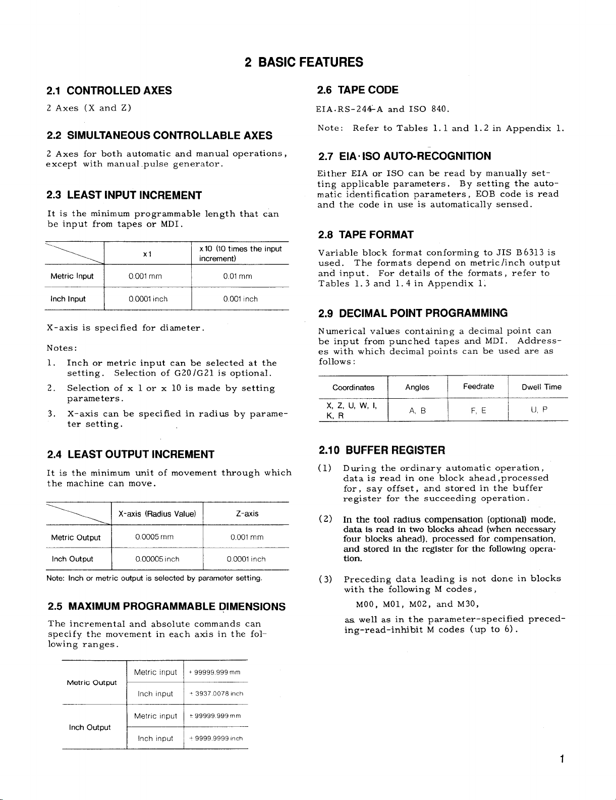
2.1 CONTROLLED AXES
2 Axes (X and Z)
2.2 SIMULTANEOUS CONTROLLABLE AXES
Axes for both automatic and manual operations ,
Z
except with manual pulse generator.
2.3 LEAST INPUT INCREMENT
It is the minimum programmable length that can
be input from tapes or MDI.
x1O (10 times the input
“-’-’J “ 1
Metric Input 0.001 mm 001 mm
Inch Input
X-axis is specified for diameter .
Notes:
Inch or metric input can be selected at the
1.
setting.
Selection of x 1 or x 10 is made by setting
2.
parameters.
X-axis can be specified in radius by parame-
3.
ter setting.
0.0001 Inch 0.001 Inch
Selection of G20/G21 is optional.
increment)
2.6 TAPE CODE
EIA. Rs-24&A and ISO 840.
Note: Refer to Tables 1.1 and 1..2 in Appendix 1.
2.7 EIAoISO AUTO-RECOGNITION
Either EIA or 1S0 can be read by manually setting applicable parameters, By setting the automatic identification parameters, EOB code is read
and the code in use is automatically sensed.
2.8 TAPE FORMAT
Variable block format conforming to JIS B 6313 is
used.
and input.
Tables 1.3 and 1.4 in Appendix 1.
The formats depend on metric /inch output
For details of the formats , refer to
2.9 DECIMAL POINT PROGRAMMING
Numerical values containing a decimal point can
be input from punched tapes and MDI. Addresses with which decimal points can be used are as
follows :
Coordinates
x, z, u, w, 1,
KR
Angles Dwell Ttme
B
A,
I
F, E
1
~ U,p
2.4
LEAST OUTPUT INCREMENT
It is the minimum unit of movement through which
the machine can move.
X-axis (Radius Value)
Metric Output
Inch Output
Note: Inch or metric output is selected by parameter setting.
I 0.0005rnrn I 0,001 mm
0.00005 Inch O0001 Inch
Z-axis
2.5 MAXIMUM PROGRAMMABLE DIMENSIONS
The incremental and absolute commands can
specify the movement in each axis in the fol–
lowing ranges .
Metric Output
s
Inch Output
=
2.10 BUFFER REGISTER
During the ordinary automatic operation,
(1)
data is read in one block ahead, processed
for, say offset,
register for the succeeding operation.
(2)
In the tool radius compensation (optional) mode,
data is read in two blocks ahead (when necessary
four blocks ahead), processed for compensation,
and stored in the register for the following operation.
preceding data leading is not done in blocks
(3)
with the following M codes,
MOO, MO1, M(i2, and M30,
aa well as in the parameter-specified preced–
ing-read–inhibit M codes (up to 6) .
and stored in the buffer
1
Page 9

2.11 RAPID TRAVERSE RATE AND FEEDRATE
The rapid traverse feed, manual feed, and rapid
feed override F~ can be set to the upper limit
s hewn below.
Metric Input
Inch Input
Notes:
Depending on the motor and machine systems,
1.
the upper limit is further restricted.
The upper limit for X-axis speed is half the
2.
above.
30,000 mrn/min
\ 1181.1 inches/rein
“’=-_ I Format I Range of Feed per Minute
Metric
Metric
output
Inch Input
output
Note:
Depending on the conditions of the motor or machine system,
1.
the upper limit of mm/min and inch/rein is further restricted.
2.
Thf upper limit for X–component of speed is the half of the
above values.
Input
Inch
input
Metric
Inch
Input
F50
F 32 FO.01 –F944,88 inches/min
F50 F 1. –F60960, mm/m.in
F 42 FC.01 –F24000.00 inches/mln
F1 - F24000, mmlmin
2.12 FEED FUNCTION (F-, E-FUNCTION)
Feed per revolution (G 99 mode)
(1)
F (normal feed) and E ( accurate. feed) commands can specify the tool feed rate per
rotation of spindle (mm /rev or inch/rev) .
% I‘or”a’‘
Metric
output
Inch
output
‘ ‘~’cl=+====
‘::t ~
Metric
Input
Inch
Input
The feedrates are limited by spindle-speed
S as follows :
I Range of Feed Per Revolution
E0.000004–E 19.685000 inches/rev
F 32 FO.01–F 127000 rnmirev
E34 E0.0003– E 1270.0000 mm/rev
F24
E26 I FO.OOOO1O–E50000000 inches/rev
FO.001–F50.0000 inches/rev
2.13 AUTOMATIC ACCELERATION/
DECELERATION
The following acceleration /deceleration is done
automatically.
(1) In positioning and manual feed
Linear automatic acceleration /deceleration
is done, independently for each axis.
(2) In machining feed
Exponential automatic acceleration /deceler–
ation is
cutting and normal feed, this can be set in–
dependently for each axis.
common to each axis.
v
In thread
b 1,
Metric Output
Inch Output
(The upper limit of X-component of speed
is half of the above. )
(2) Feed per minute ( G 98) mode
F command specifies the tool feedrate per
minute as follows :
] F(E) x SS24,000mrn/min
\ F(E)XS<
=2,400 inches/mln
2
2.14 FEEDRATE OVERRIDE AND
FEEDRATE OVERRIDE CANCEL
(1) Rapid traverse feed override
Rapid traverse rate can be modified to F(I
and 25, 50, and 100% of the original traverse rate.
by parameter .
(2) Feed override
The F-commanded feedrate can be modified
in the range of O to
The FO is a constant speed set
200% in 10% increments.
Page 10

(3) Override cancel
Turning this switch on cancels any override
effect , causing the tool to move at the origi–
nally specified speed.
2.15 PREPARATORY FUNCTION (G-FUNCTION)
The address G and the following numerals up to
3 digits specify a block and its meaning. For
details of G-codes, refer to Table 1.6 in Appendix 1,
(1) Ordinary G-codes
a. G codes in 01 to 11 groups are modal.
Once specified, the y are effective until
other G-codes in the same group are
specified.
b. G codes in *-marked groups are” non-
modal, and effective only in the specified
block .
(2) Special G codes
a. Special G code I can be used in the basic
mode (by parameter switching) .
b. Special code ~ is optional.
2.16 ABSOLUTE/lNCREMENTAL
PROGRAMMING (G90/G91)
Absolute programming (X, Z, G90)
(1)
Addresses X and G are used to specify an
absolute value.
II, X and Z commands in G90 mode specify
an absolute value.
address U and W remain as incremental com–
mands.
(2)
Incremental programming (U, W, G91)
Addresses U and W are used to specify an
incremental value . In the use of special
code I or II , X and Z commands in G91 mode
specify an incremental value .
Combined command
(3)
In the same block,
X.. .;or U; Z; U.. .Z;
can be ‘used as a combined command.
In the use of G90 or G 91, however, both
cannot be specified in the same block.
Addresses 1,
(4)
lation are invariably incremental values.
In use of special code I or
However, in G90 mode,
K , and R for circular interpo-
2.17
PROGRAMMING OF ABSOLUTE ZERO
POINT (G50)
G50 X.. , Z.. . ;
(1)
This command establishes the absolute coordinate system ( = coordinate system) such
that the current tool position becomes the
specified coordinate value.
G50 U.. . W.. .
(2)
This command establishes a new coordinate
system in which the coordinate system already established with G50 has been shifted
by incremental value U. W.
2.18
POSITIONING (GOO)
GOO
x(u) . . . z(w) . . . ;
This
command moves the tool to the specified
position at rapid traverse rate and independently
for each axis.
ar.
The GOO is a modal G-code. In GOO positioning, pulse distribution is started after ERROR
DETECT ON , and after distribution, when ERROR
DETECT ON is again detected, operation goes to
the next block.
The travel is not necessarily line-
; (incremental setting)
2.19 POSITIONING IN ERROR DETECT OFF
MODE (G06)
G06 x(u) . . . z(w) . . . :
Positioning by this command differs from GOO
following ‘points:
the
a.
G06, being non-modal, is effective only ir
the specified block.
b.
G06 starts pulse distribution without ERROR
DETECT ch-eck, and after distribution is com-
pleted, immediately goes to the next block.
In G06 positioning , the corners of workpiece
are slightly rounded.
Note: ERROR DETECT ON means the state where
the servo-lag pulses are reduced to a permissible
number .
and the actual tool position nearly coincide.
At this time the command pulse position
n
2.20 LINEAR INTERPOLATION (GO1)
GO1 X( U)... Z(w) . . . F(E) . . . ;
This command moves the tool to the specified target position along a straight line at the specified
feed rate.
3
/
Page 11
2.21
CIRCULAR INTERPOLATION (G02, G03)
(1)
:~&GO 3 )
. . .
Z(W) . . . 1.. . K.. . F(E) . . . ;
2.24 AUTOMATIC RETURN TO REFERENGE
POINT (G28)
G28 X( U).,. Z(W) . . . ;
(1)
This command moves the tool to the specified
end position along the specified circular path.
G02: Circular interpolation in’ @ockwise (CW)
G03: Circular interpolation in counterclock-
(2)
Circular interpolation is possible across
multiple quadrants or along the full circle.
Notes: Optionally,
fied by r~dius R.
2.22
(1)
This command causes the tool to remain motionless for the time specified by U or P
before the program goes to the next block.
(2)
wise (CCW)
X(U) , Z(W) : End position
I, K:
F(E) :
X- and Z-components of the center
of the circular path with respect to
the starting point.
Feedrate in the tangential direction
of the arc.
a circular path can be speci–
DWELL (G04)
G04 U(P) . . .
The dwell can be increased to a maximum of
8388.607 seconds in increment of 0.001 sec-
ond.
A numerical value containing decimal
point can be specified.
G04 U3.5 ;
;
--- A3. 5-seconds dwell
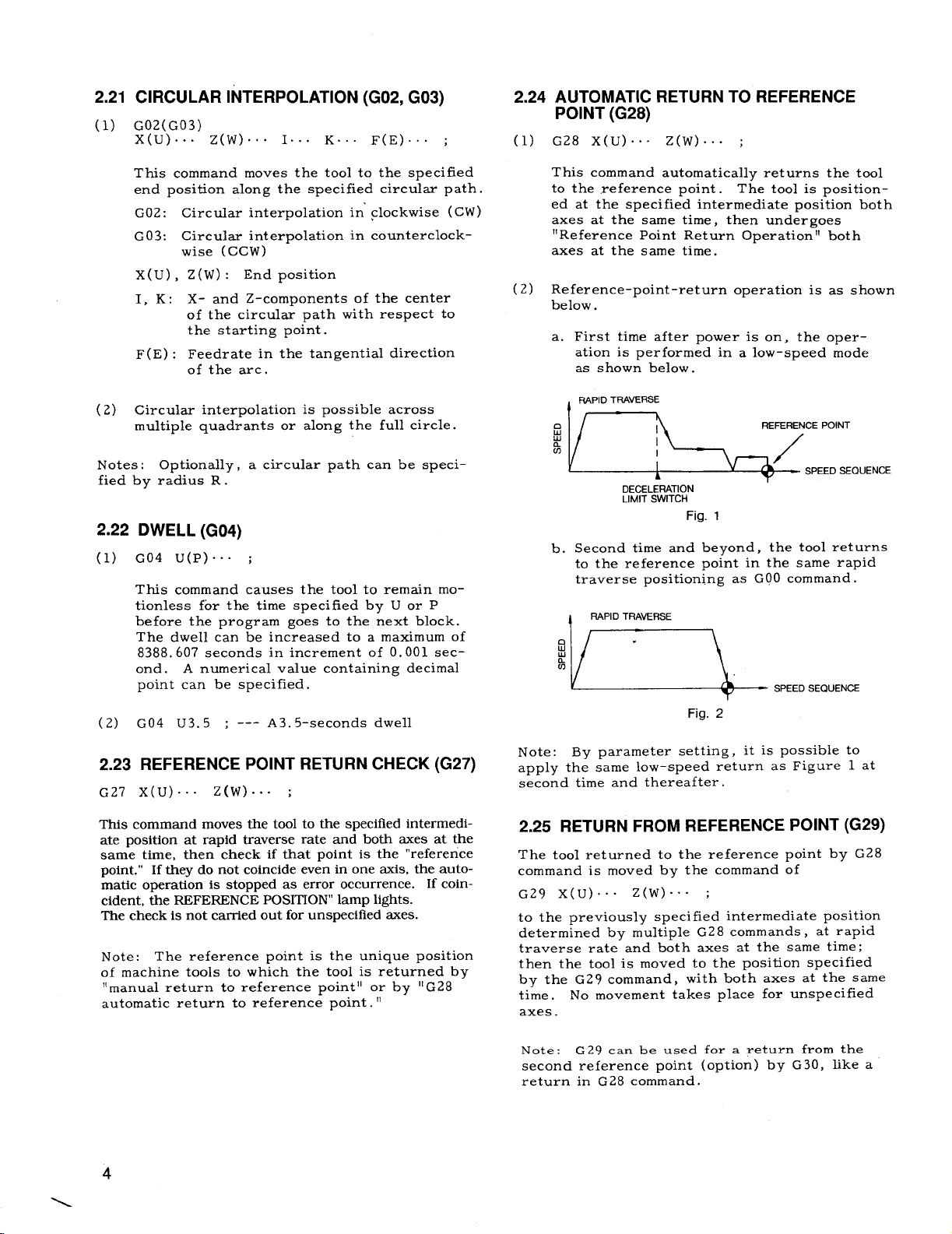
This command automatically returns the tool
to the reference point . The tool is positioned at the specified intermediate position both
axes at the same time , then undergoes
!lRe feren~e point Return Operation 11both
axes at the same time.
Reference-point-return operation is as shown
(2)
below.
a. First time after power is on, the oper-
ation is performed in a low–speed mode
as shown below.
‘=Z:QUE
b. Second time and beyond, the tool returns
\.
DECELERATION
LIMIT SWITCH
Fig. 1
to the reference point in the same rapid
traverse positioning as GOO command.
RAPID TRAVERSE
<
‘u.-,.-
Fig. 2
2.23 REFERENCE POINT RETURN CHECK (G27)
G27 X( U)... z(w) . . . ;
l%is command moves the tool to the specified intermedi-
ate position at rapid traverse rate and both axes at the
same time, then check if that point is the “reference
point.”
matic operation is stopped as error occurrence. If coincident, the REFERENCE POSITION” lamp lights.
The check is not carried out for unspecified axes.
Note: The reference point is the unique position
of machine tools to which the tool is returned by
“manual return to reference point” or by 11G28
automatic return to reference point. ”
4
If they do not coincide even in one axis, the auto-
Note: By parameter setting, it is possible to
apply the same low-speed return as Figure 1 at
second time and thereafter.
2.25 RETURN FROM REFERENCE POINT (G29)
The tool returned to the reference point by G28
command is moved by the command of
G29 X( U)... ‘2(W)””” ;
to the previously specified intermediate position
determined by multiple G.28 commands , at rapid
traverse rate and both axes at the same time;
then the tool is moved to the position specified
by the G29 command, with both axes at the same
time.
axes.
Note : G 29 can be used for a return from the
second reference point (option) by G30, like a
return in G28 command.
No movement takes place for unspecified
Page 12
2.26
MULTI-START THREADCUTTING (G32)
G32 X( U)... Z(W) . . . F(E) . . . ;
(1)
This command allows straight thread, taper
thread, and scroll thread to be cut.
Type of Thread
Commands
*––––––––––––J
s
G32
r-
G32
-z
Straight Thread
Taper Thread
Scroll Thread
F specifies ordinary thread lead; E precise
thread lead.
sPeclficatlon is the same as the command
range of feed per revolution (mm /rev or
inch/rev) in 2.14 Feed Function.
(2)
Continuous thread cutting
G32 X( U)... Z(W)” OO F(E) . . . ;
x(u) . . .
x(u) . . . z(w) . . . ;
With this type of continuously programmed
block command for threading,
ting is allowed to continue to the next thread
cutting operation, reducing the stop time to
110.!1
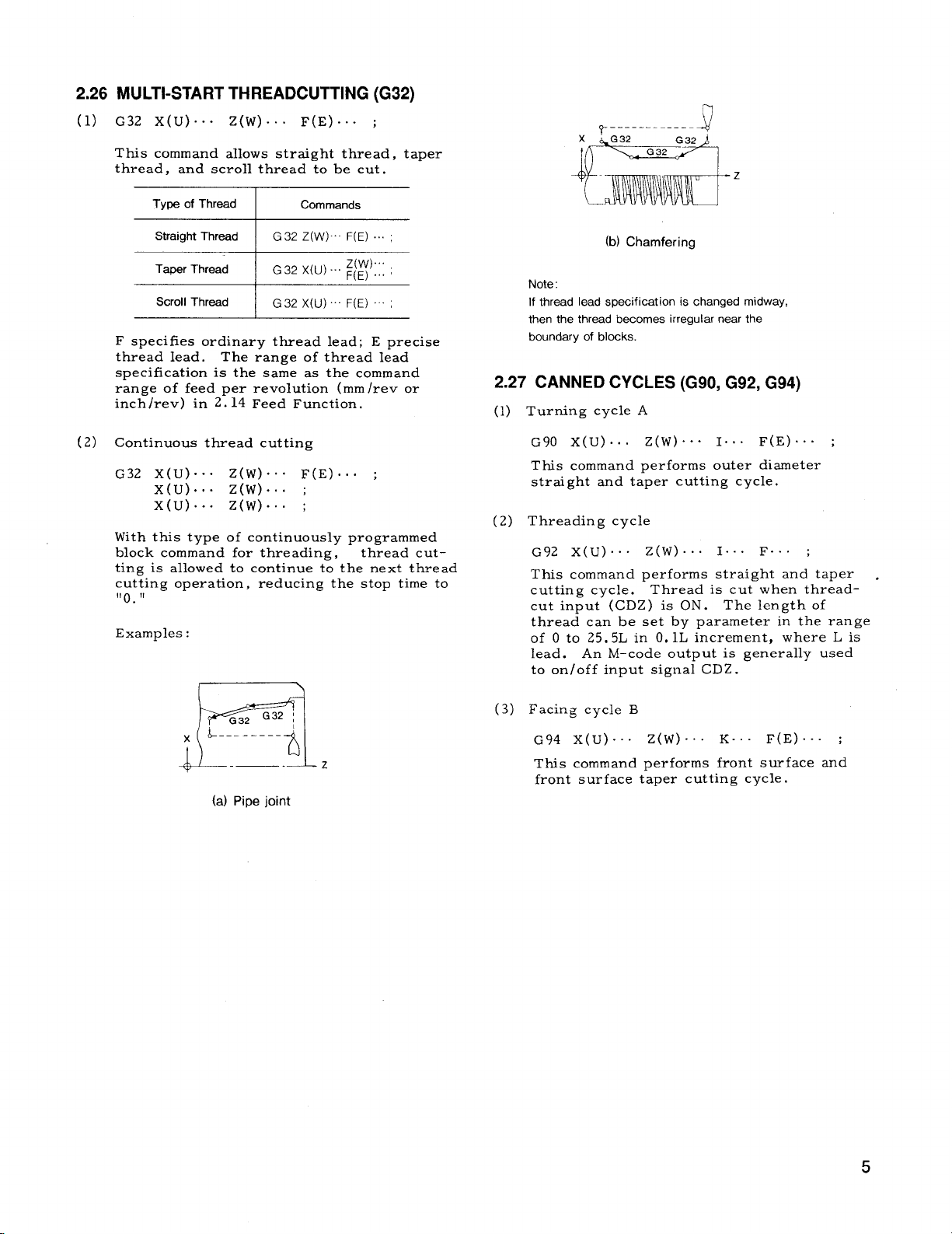
Examples :
I G32 Z(W) F(E) ~~~~
G32 X(U) ~(~) ... .
I
G32 X(U). F(E) ~~~;
The range of thread lead
z(w) ... ;
z(w).
thread cut-
(b) Chamfering
Note:
If thread lead specif icat ion is changed midway,
then the thread becomes irregular near the
boundary of blocks.
2.27 CANNED CYCLES (G90, G92, G94)
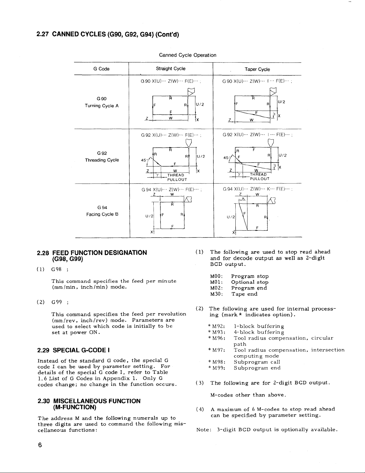
(1) Turning cycle A
G90 X( U)... Z(W)””” 1.. . F(E). . . ;
This command performs outer diameter
straight and taper cutting cycle.
(2) Threading cycle
G92 X( U)... Z(w) . . . 1.. . F“. ” ;
This command performs straight and taper .
cutting cycle.
cut input (CDZ) is ON. The length of
thread can be set by parameter in the range
of O to 25, 5L in O. lL increment, where L is
lead.
to on/off input signal CDZ.
An M-code output is generally used
Thread is cut when thread-
~32 G32 :
~ L-------- ‘
II
E=l
(a) Pipe joint
z
(3) Facing cycle B
G94 X( U)... Z(W)””. K.. . F(E)””” ;
Ttis command performs front surface and
front surface taper cutting cycle.
5
Page 13
2.27
CANNED CYCLES (G90, G92, G94) (Cent’d)
Canned Cycle Operation
G Code
G 90
Turning Cycle A
G 92
Threading Cycle
G 94
Facing Cycle B
Straight Cycle
G90 x(u).. Z(W) F(E). ,
R
u/2
F
z
R
450
d
z w
q+__J
Y THREAD
G94 X(U) Z(W) F(E) ,
z
u/2 F
p
x
R
F
w
R
R U12
F
PULLOUT
w
R
R
F
Taper Cycle
G90 X(U)... Z(W).. I “’” F(E)’””,
w
2
R
F
x
x
=$!
L
G92 X(U).. Z(W)... I . F(E). ;
F
R
45” F
z
Q
G94 X(U) Z(W).. K F(E)..
u/2
TH!EAD
Y
PULLOUT
z
K
F
~H
x
Jx
I-Y
R u/2
F
]X
w
R
R
F
2,28
FEED FUNCTION DESIGNATION
(G98, G99)
G98 ;
(1)
This command specifies the
(mm /rein, inch /rein) mode.
G99 ;
(2)
This command specifies the
(mm /rev, inch /rev) mode.
used to select which code is initially to be
set at power ON .
2.29
SPECIAL G-CODE I
Instead of the standard G code, the special G
code I can be used by parameter setting.
details of the special G code 1, refer to Table
1.6 List of G Codes in Appendix 1. Only G
codes change; no change in the function occurs.
feed per minute
feed per revolution
Parameters are
For
2.30 MISCELLANEOUS FUNCTION
(M-FUNCTION)
The address M and the following numerals up to
three digits are used to command the following mis–
cellaneous functions:
The following are used to stop read ahead
(1)
and for decode output as well as 2–di git
BCD output.
MOO: Program stop
MOl: Optional stop
M02: Program end
M30:
(2)
The following are used for internal process-
ing (mark * indicates option) .
* M92: l-block buffering
* M93:
* M96:
*M97:
* M98:
* M99: Subprogram end
The following are for 2-digit
(3)
M-codes other than above.
A maximum of 6 M-codes to stop read ahead
(4)
can be specified by parameter setting.
Note:
Tape end
4-block buffering
Tool radius compensation, circular
path
Tool radius compensation, intersection
computing mode
Subprogram caIl
BCD output.
3-digit BCD output is optionally available.
6
Page 14
2.31 SPINDLE-SPEED FUNCTION (S-FUNCTION)
Spindle speed function called S 4-digit
programming A is executed.
The spindle rpm can be designated by com-
(1)
mand consisting of address S followed by
4 digits, instead of the basic S 2-digit corn, -
mand. As the output to the machine
(spindle) , an analog voltage (t10 V max. )
is output from the DA converter.
The control makes necessary computation to
(2)
meet the programmed rpm, outputs the signals (up to 4 signals) to shift the spindle
gear ratio, and outputs an analog voltage
or 12-bit binary signal suited to the shifted
gear ratio. The speed ranges and other required data are set by parameters.
The maximum spindle rpm can be designated
(3)
by G50S command.
TOOL FUNCTION (T-FUNCTION)
2.32
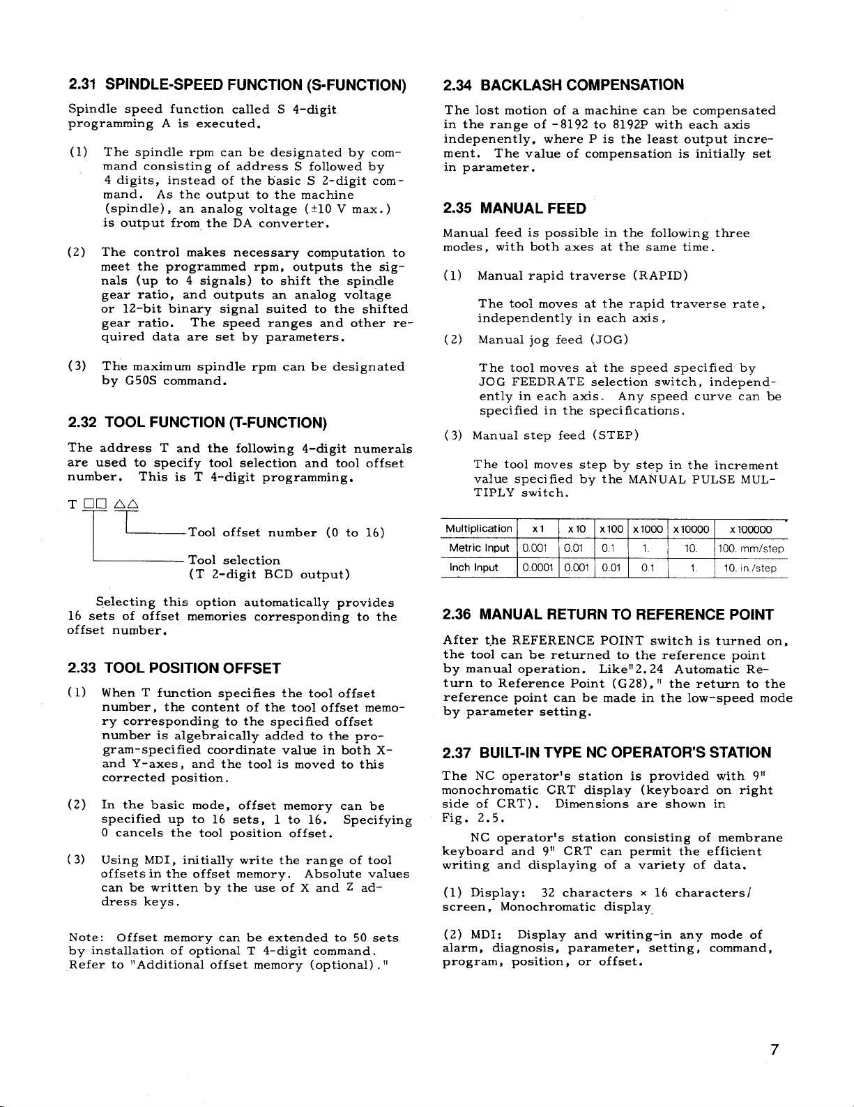
The address T and the following 4-digit numerals
are used to specify tool selection and tool offset
number.
This is T 4-digit programming.
2.34 BACKLASH COMPENSATION
The lost motion of a machine can be compensated
in the range of -8192 to 8192P with each axis
indepenently, where P is the least output increment, The value of compensation is initially set
in parameter.
2.35 MANUAL FEED
Manual feed is possible in the following three
modes,
(1)
(2)
(3)
with both axes at the same time.
Manual rapid traverse (RAPID)
The tool moves at the rapid traverse rate,
independently in each axis,
Manual jog feed (JOG)
The tool moves at the speed specified by
JOG FEEDRATE selection switch, independently in each axis.
specified in the specifications.
Manual step feed (STEP)
The tool moves step by step in the increment
value specified by the MANUAL PULSE MUL–
TIPLY switch.
Any speed curve can be
~Tool offset number (O to 16)
I
~ Tool selection
(T 2-digit BCD output)
Selecting this option automatically provides
16 sets of offset memories corresponding to the
offset number.
2.33 TOOL POSITION OFFSET
(1) When T function specifies the tool offset
number, the content of the tool offset memory corresponding to the specified offset
number is algebraically added to the pro-
gram-specified coordinate value in both Xand Y-axes, and the tool is moved to this
corrected position.
(2) In the basic mode
specified up to 16 sets, 1 to 16.
O cancels the tool position offset.
(3) Using MD1, initially write the range of tool
off sets in the offset memory. Absolute values
can be written by the use of X and Z address keys.
, offset memory can be
Specifying
Multiplication
Metric Input
Inch Input
xl
x 10 Xloo x 1000 x 10000 x100000
1
0001 I 001 01 1
0.0001 0.001 0.01 01 1 10. In /step
10,
100. mm/step
2.36 MANUAL RETURN TO REFERENCE POINT
After the REFERENCE POINT switch is turned on,
the tool can be returned to the reference point
by manual operation.
turn to Reference Point (G28) , “ the return to the
reference point can be made in the low-speed mode
by parameter setting.
Like” 2.24 Automatic Re–
2.37 BUILT-IN TYPE NC OPERATOR’S STATION
The NC operator!s station is provided with 911
monochromatic CRT display (keyboard on right
side of CRT) .
Fig. 2.5.
NC operator’s station consisting of membrane
keyboard and 911 CRT can permit the efficient
writing and displaying of a variety of data.
(1) Display: 32 characters x
screen, Monochromatic display
Dimensions are shown in
16 characters
Note:
by installation of optional T 4-digit command.
Refer to “Additional offset memory (optional) . “
Offset memory can be extended to 50 sets
(2) MDI:
alarm, diagnosis, parameter, setting, command,
program, position, or offset.
Display and writing-in any mode of
7
Page 15

2.38 PART PROGRAM STORAGE AND “EDITING
Part programs can be loaded into memory for tape–
less operation and for editing.
Storage capacity is equivalent to 40 meters
(1)
of tape. (Note 1. )
M99 P.. . ;
If this command is added to the end of the
program, control returns to the P-specified
sequence number in the main program.
(3)
Multiple call
(2)
Part program, added with a program number
of 4–digit numerals,
(from paper tape or MD1) . In the basic
mode, Up to 99 program numbers can be
stored in memory. (Note 2.)
(3)
The stored part program can be- edited by
ERASE, INSERT , and ALTER keys. Editing is done in one to several words at a time.
(4)
The OUT, VER, and IN keys are used to
output the stored part programs to external
equipment, to collate them with
punched cards, and store them from tape
readers (Note 3. ) (option) .
(5)
Address search function permits the speci-
fied program number to b-e searched for the
purpose of an automatic operation (MEM mode)
Notes :
1. Optionally, the part program storage may be extended
to 320 meters.
2. Optionally, the number of stored programs may be
extended to 999.
3. To output the part program to an external equipment,
the optional “RS232C interface” is required.
can be stored in memory
2.39 SUBROUTINE PROGRAM (M98, M99)
A subprogram can call nested subpro-
grams up to 4 times successively.
2.40
PARAMETER STORAGE
Parameters for machine constants such as backlash compensation values and rapid traverse rate
can be set to determine or change the specifica–
tions. Set parameters while the SYSTEM switch
No. 1 is set at No. 1 and the control in idle
condition.
2.41 SETTING FUNCTION
Any of the functions can be selected to on or off.
This is possible if the SYSTEM No. switch is set
to normal “O. “
2.42 INTERNAL DATA TAPE INPUT
Normally, tool offset values, parameter data, and setting
data are input from the MD1. These data may be stored,
via RS232C interface, in respective memories.
Note:
ternal equipment by installing optionaI RS232C
interface. (Example output: tape punch out,
type out)
These stored data may be output to an ex-
Subprogram Call (M98)
(1)
M98 P.. . Q.. . L.. . ;
With this command, the subprogram starting
with sequence number Q is called from the
part programs having the program number
specified by P and the subprogram is executed L times.
If P is omitted, the subprogram starting
with sequence number Q is called from the
main program.
If Q is omitted, the starting subprogram
having P-specified program number is called.
If L is omitted, the execution is only once.
Subprogram end (M99)
(2)
M99 ;
This command is added to the end of the
subprogram to end it.
the subprogram,
block immediately following the main pro-
gram that has called the subprogram.
control returns to the
After completion of
8
2.43 OPERATION TIME DISPLAY
The cumulative time of the following operations
can be displayed:
(1) Total time after switching power supply on:
POWER ON
(2) Total time of automatic operation: CYCLE
START
(3) Total cutting time ( during interpolation
moving) : FEED
TIMER
HOUR MIN SEC
TMI :
0012. 34. 56
TM2: 0001. 02. 59
TM3: 0000. 36. 38
The above time display is stored after power is
turned off.
operation from the panel.
The display can be reset to O by
Page 16

2.44 ADDRESS SEARCH
Through MDI operation,
for: on NC tape (TAPE mode) or on part program (MEM, EDT mode) . Either single address
data or arbitrary data up to 32 characters can
be searched.
numbers can also be searched for.
Example
=
Data consisting of any type and arrangement of
characters can be searched.
Program numbers and sequence
all data can be searched
2.45 PROGRAM NUMBER
A program number can be a maximum of 4-numeri-
cal digits following the address O. It can be written
at the head of the program.
2.46 LABEL SKIP
The label skip function is effective and message
“LSK” is displayed on the lower part of CRT
while:
(1) The power supply is being turned on, and
2.51
MACHINE LOCK AND DISPLAY LOCK
OFF
DISPLAYLo.K/’’’--lMAcHlN, ,0..
0
Off Condition
(1)
Normal automatic and manual operations are
carried out in off condition.
(2)
Machine lock condition
In machine lock condition, NC commands are
executed while the machine is standing still.
M, S, and T functions operate normally,
and the current position is continuously up–
dated and displayed. The same applies to
manual operation.
(2) Control is being reset.
When the label skip function is effective , all the
tape information before the first FOB code is
ignored. In the MEM or EDIT mode, “LSK” display means that a pointer is at the head of the
selected part program.
2,47 CONTROL lN/OUT
Data between a control out “(” and a control in
“ ) “ is ignored as insignificant.
2.48 SINGLE BLOCK
When the SINGLE BLOCK switch is turned on,
automatic operation with tape or memory is performed block by block.
2.49 OPTIONAL BLOCK SKIP
With the OPTIONAL BLOCK SKIP switch on, data
is ignored from command “ /“ of “ /1” to EOB on
a block.
2.50 DRY RUN
With the DRY RUN switch on, the feedrates for
automatic operation (rapid traverse and F(E)
specified feedrates) are ignored and the follow-
ing feedrates are available. This dry run func–
tion is used to test programs .
Display lock condition
(3)
In display lock condition, the machine moves
normally, but no change occurs in the dis–
plays of the current value ,external and the
current value (optional) . These displays
do not change if feed is done manually.
2.52 AUXILIARY FUNCTION LOCK
While this switch is on,
for M, S, and T functions. However, the oper-
ation is normal for decoding MOO, MO1, M02, and
M30, and for internal handling of M codes (M90
to M109) .
Note: The miscellaneous function lock does not affect S-4
digit command (option)
2.53
MANUAL ABSOLUTE ON/OFF
While ON
(1)
Manual movement distances are added to the
absolute register, and the coordinate system
remains unchanged.
While OFF
(2)
Manual movement distances are not added,
and the coordinate system is shifted in parallel to the movement.
no BCD code is output
9
Page 17

2.54 EDIT LOCK
With this switch on,
ations are inhibited.
a. ERASE, INSERT,
b. NC tape storing operation.
the following editing oper-
and ALTER key operations.
2.55 INTERLOCK
When an interlock signal is on during automatic
operation, the tool stops after deceleration in
both X and Z axes; when the signal is cleared,
the tool resumes the motion.
2.61 OVERTRAVEL
This function is to stop the tool motion by receiving a stroke–end signal from the machine.
the machine is stopped by this function, the
machine member must be moved backward by
manual feed.
When
2.62 REMOTE RESET
This function is to reset the NC with an external
signal.
tive, and tool motion is stopped.
When reset ,
all commands become ineffec-
2.63 REMOTE POWER ON/OFF
2.56 RAPID PULL OUT OF THREADING
When this signal is input, thread is cut during
thread cutting cycle of G92 and G76X. When the
signal is off, thread is not cut. In normal usage,
any M codes are output if this signal (CDZ) is
turned on and off.
2.57 ERROR DETECT
While this signal is turned on, operation goes to
the next block after pulses are distributed for
feed and ERROR DETECT is on (square corner) .
If the signal is off, the operation goes to the
next block immediately after pulses are distributed.
In normal usage, if any M codes are output, then
this signal (SMZ) is turned on and off.
Note: This function is effective only for feed.
The error detect for positioning is controlled only
by GOO and
G06.
2.58 DOOR INTERLOCK
When the door is open, the power supply is turn-
ed off.
2.59 FEED HOLD
Depressing this pushbutton temporarily interrupts
the tool feed during automatic operations. It does
not function, however , to stop thread cutting.
The operation is resumed by depressing CYCLE
START pushbutton.
2.60 EMERGENCY STOP
Depressing the EMERGENCY pushbutton makes
all commands ineffective.
ply is turned off, and all moving members are
stopped by dynamic brake.
The servo power sup-
In addition to the POWER ON /OFF pushbutton on
the NC operator’s station, the power can be turned on and off by inputting an external contact
signal.
2.64 MACHINE READY INPUT SIGNAL
This signal indicates on the control that the machine is ready for operation.
possible when the signal is received in the con-
dition of “Servo Power ON . “ When the signal is
off during operation, all functions are stopped,
with “Machine Unready. “
The operation is
2.65 CONTROL POWER ON OUTPUT SIGNAL
An output signal to indicate that the power is
input to the control section.
2.66 SERVO POWER ON OUTPUT SIGNAL
An output signal to indicate that the servo power
is normally input in the condition of NC power-on.
2.67 TOOL MOVE OUTPUT SIGNAL AND
THREADCUTTING OUTPUT SIGNAL
Moving Signal
(1)
An output signal to indicate the tool is moving
in automatic operation mode.
(2)
Threading Signal
A signal to be output specifically during
thread cutting..
2.68 NC ALARM OUTPUT SIGNAL
A signal to be output during any one of alarms
except for inpur error. The signal is off
immediately after the cause is removed and the
reset procedure is followed.
10
Page 18

2.69 INPUT ERROR OUTPUT SIGNAL
A signal to be made on by an error relating to
program input, such as one in part program
parity, format, or numerals. The signal is turn
ed off by reset operation.
output for a
“Simple Error” displayed on CRT.
The signal is not
2.70 NC RESET OUTPUT SIGNAL
A signal to be turned on by pushing the reset
key on the NC operator’s station or by input
of external reset signal.
(3) Input /Output Signal Diagnosis
2.74 POSITION DETECTOR INTERFACE
Position and speed is detectec by feedback signal
from the rotary-type pulse generator. (Note 2. )
The motion per rotation of the pulse generator is
varied by the number of pulses from the pulse
generator as shown in the table below.
Pulse Generator
Motion per Rotation of
Pulse Generator
EXTERNAL ERROR INPUT SIGNAL
2.71
External Error Detect Input O
(1)
When this signal is input, the operation
stops after the end of the current block,
and alarm is displayed.
External error detect input 1
(2)
When this signal is input, the current mo-
tion is immediately stopped, and alarm is
displayed.
2.72
RS-232C INTERFACE PORT
RS-232C interface is provided to connect tape
puncher, separate type tape reader unit and
other external equipment.
Interface Type
Transmission speed 110 to 9600 baud
Connector
Max Cable Length
Output from Memory
Storage in Memory
Tape Mode Operation
Note : Data which are output from memory
or stored in memory are as follows :
. Part program
. Offset data, tool coordinate data
and tool wear data
. Setttng and parameter data
Serial voltage interface
—
DB-25S
15 m
Possible
Possible
Possible
Metric
output
E=..
The “motion per rotation of pulse generator” in
X-axis is the half of the above values.
Note: The multiplication of pulses can be set
from servo unit and the NC.
2.75 lNPUT/OUTPUT CONNECTORS
The connection of the machine and the NC control is made
via “Half pitch connectors” directly to the CPU rack.
2.76 POWER INPUT
The standard input power is as follows:
200/220/230 VAC, +10%, -15%, 50/60 HZ fl Hz,
3-phase
2.77 AMBlENT CONDITIONS
(1) Ambient Temperature
(2) Relative Humidity: 10% to 90% RH
For operation: 0° C to +450 C
For storage:
-20° C to +65°C
2.73 ON-LINE DIAGNOSTICS
During operation, the following self-diagnoses
are made online:
(1) 3-digit Alarm Code and Alarm Message Dis-
play.
(2) System Diagnosis
a. System memory total check.
b. RAM check (when power is input) .
c. Watchdog timer.
(3) Vibration:
Note: When the ambient conditions do not con-
form to the above requirements, or organic solvent or other fumes are present in high concentration,
we offer special measures.
4.9 mis’max.
11
Page 19

2.78 SPINDLE PULSE GENERATOR
This provides the spindle position detector connected to the lathe spindle with 1 : 1 ratio.
number of pulses are :
The
a. 4000 rpm max.
b. 6000 rpm max.
(provided with oil seal)
(not provided with oil seal)
3 BASIC
3.1 AC SERVO CONTROL UNITS
Transistorized PWM servo control units are further miniaturized to be available for use in either
of the folIowing systems:
(1) NC board built-in system:
Built in the free-standing type cabinets.
(Z) External install system:
Supplied in unbundled type to the freestanding type cabinets.
to be less than 10 meters (30 feet) .
Servo capacity is as follows :
No.
--+
1
2
3
4
Continuous Max
Torque of F Series
AC Servomotor
30kg cm
60 kg cm SR1OBB
I
90 kg cm
120kgcm
Cable connection
Type
CACR -
SR05BB
I
SR15BB
SR20BB
OPTIONS
3.2 AC SERVOMOTORS
The following AC servo motors that incorporate
the position-detecting pulse generator (PG) and
speed–detecting pulse generator (PG) are avail–
able.
rpm.
The rated speed of AC servomotor is 1500
No.
2
4
6
* II; indicates depending on detector type(P/rev)
as follows:
Continuous Max Torque
of F Series AC Servomotor
1 30 kg. cm
60 kg-cm
3
5
A: 6000 P/rev
B: 5000 P/rev
90 kg-cm
120 kg-cm
230 kg.cm
380 kg-cm
Type
USAFED-
05F[:; *
09F[;
13F::;
20F[:;
30F[.;
44F[:;
5 230 kg cm
6
I
12
380kg cm
I
SR30BB
SR44BB
Page 20

4.1 SEPARATE TYPE NC OPERATOR’S
STATION
The separate stations are available in two configurations :
“ Keyboard on right side of CRT
(The power on~off push button not provided)
See Fig.” 2.2.
Keyboard below CRT
-
See Fig. 2.3.
4.2 SEPARATE TYPE TAPE READER
The separate type tape reader can be
to the NC contr~l th~ough RS- 232C interface
port 1.
- Read speed: 200 char. /see
● Reading system:
LED-photoelectric
connected MEMORY \30 SETS MAX. ) _
4.3 TAPE READER WITH REELS
*
WORK COORDINATE
SYSTEM SHIFT MEMORY ~ CO
* TOOL COORDINATE
(0NE SET)
TOOL OFFSET
MEMORY -
(50 SETS MAX )
f-
k
---
1
* TOOL RADIUS —
MEMORY
TOOL OFFSET NUMBER
No.
01
09
10
16
—-
17
50
51
@o
81
99
_——
--- ____.__..
STANDARO T 4- DIGIT
‘ COMMAND
(BASIC)
J
ADDITIONAL OFFSET
MEMORY *
J
Attached type 1 can be provided with
reader with reels.
(1) 6-inch reel
Reel diameter: 150 mm (6 inches)
Tape length:
Tape thickness: O. 108 mm
The tape reader speed determines
and rewind speed.
80 m (262 ft. )
the following tape
tape read
4.4 M3-DIGIT BCD OUTPUT
A digit is added to the basic M 2-digit BCD output to provide a total of M 3-digit BCD output.
M codes being output are MOO to M89 and M11O to
M999.
4.5 ADDITIONAL TOOL OFFSET MEMORY
To meet T 4-digit command, 50 sets of offset memories are available to replace 16 sets.
The map of offset memory including other options
are shown as reference.
4.6 ADDITIONAL PART PROGaRAM STORAGE
Any of the following storage capacities can be
selected to replace the memory equivalent to the
basic tape len-gth of 40 meters.” “
31
320 m (1049 ft.)
4.7 ADDITIONAL PROGRAM NUMBER
REGISTRATION
Either of the following number of registrable programs can be selected to replace the basic number
of 99.
Total Number of Registrable Programs
+t=-
13
Page 21

4.7 ADDITIONAL PROGRAM NUMBER
REGISTRATION (Cent’d)
Note that if the optional
ber registration” is adopted, the storage capacity
for the part program is reduced by the following
amount.
Additional Number
of Registered Programs
“additional program num-
Reduced
Storage Capacity
4.10 INTERNAL TOGGLE SWITCHES
Input to the following 8 switches (all basic)
can be turned on and off by setting operation on
the NC control panel (Setting #6000) .
0 Single block
1: Machine lock
2: DIsP@ lock
3: Optional block skip
(Block delete)
4: Dry run
5: Manual absolute
6: Miscellaneous functim lock
7: Edit lock
199
999
\ 2m (66ft)
18m (59 ft.)
I
4.8 OPERATION TIME DISPLAY B
The CRT displays the cumulative time while the
external signal (EXTC) is being input.
HOUR MIN
TM4: 9999. 59.
SEC
59 max.
4.9 STEP-MODE SIMULTANEOUS ONE-AXIS
OPERATION
The step-mode of operation is enabled one–axisat–a-time using the axis selection switch.
axis moves by the amount of turning of the
manual pulse generator. The manual pulse gen–
erator is graduated in 100 scales per rotation.
The motion per rotation can be specified by the
manual step multiple selection switch as follows:
Multiplication
Switch
Metric Input [ 0001mm I O.Olmm I Olrnrr
xl Xlo x100 or greater
The
582-217
Example of Internal Toggle Switches CRT Display
4.11 G50 POINT RETURN
This function manually returns the tool to the po-
sition specified by G50 coordinate system setting
command.
(SRN input) and perform manual jog or manual
rapid traverse operation, then the tool automati–
tally stops at the setup position.
Turn on the Setup Point Return Switch
-+ ‘etu””’ntre’urnswitch
Inch Input 0.0001 Inch 0.001
The motion by the manual pulse generator is possible when “Automatic mode handle offset switch
(HOFS input)” is on during the automatic operation mode. This motion, however, is impossible
during execution of positioning command ( GOO,
G06) .
ative thread cutting, etc.
Notes :
1.
2. Installation of the manual pulse generator (one axis at
This function is convenient for regener-
The automatic operation mode means TAPE,
MDI (manual data input) , and MEM (memory)
operation modes .
a time) eliminates the function of manual step feed.
Inch
0.01 Inch
14
4.12 RESTART AFTER MANUAL
INTERRUPTION
This function manually returns the tool to the position where the operation has been changed from
the automatic mode to the manual to carry out a
manual operation.
Return Switch (CRRN input) , and manually feed
the tool with jog or rapid traverse in the direc-
tion at which the mode has been changed from
automatic to manual, then the tool automatically
stops at the mode-changed position.
~++ ret.rnswitch
Turn on the Interrupted-Point
Interrupted–machining point
Page 22

4.13 PROGRAM RESTART
This function resumes the program at any sequence
number. Turn on the program resume switch
(PRST input) , search for the sequence number,
and then turn off the switch.
output required M, S , and T codes, and depress
the Cycle Start button to resume the program.
RRST
I
“+
Then , use MD I to
Program restart switch
4.14 EXTERNAL INPUT, COLLATION, AND
OUTPUT
Deletion, input, collation, and output of part
program can be commanded to the part program
stored in the control by external contact input.
To execute this function, RS232C. interface is
used as the transmission line of part program
data. Data input and output interface should be
provided.
4.15 BUFFERING FUNCTION (M92, M93)
(1) 4-block Buffering (M93)
In general, these G codes are specified in a
single block at the head of program.
Notes:
Inch /metric input can be selected by setting
1.
operation (basic) .
2.
G20 /G21 command rewrites the above setting
data.
ther G20 or G21 at the time of power on.
Thus , the setting data determines ei-
4.17 RADIUS PROGRAMMING FOR
CIRCULAR INTERPOLATION (G22, G23)
G22(G23) X( U) O.. Z(W) .”. R,. . F(E) . . . ;
This command specifies the radius of an arc by
address R instead of specifying the center of arc
by I and K. Note that:
Where R > CI:
R< I):
Note:
by GOZ and G03 instead of GZ2 and G23 respectively.
The radius-designated arc can be specified
an arc less than 1800,
an arc greater than 1800
The “M93 ;”
read-ahead mode until “M92” command is
issued.
ing 4 blocks is stored in the buffer for the
succeeding operations.
ahead in 4 blocks contains a program whose
operation time is longer than the time needed to read and compute the data in the 4
blocks following the above 4, then stop time
between blocks is eliminated. Thus, this is
effective in avoiding bright streaks on works
that might be caused by stop time between
blocks .
(2) l-block Buffering (M92)
The “M92 ; “
read–ahead mode and the operation returns
to the normal l--block read-ahead mode.
Note: During tool radius compensation in M93
mode, a maximum of 6-block read– ahead mode
might occur,
block without move command.
command specifies a 4-block
The data read ahead in the follow-
If the data read
command cansels the 4–block
because 2 blocks are allowed as the
4.16 lNCH/METRIC SETTING
The following G codes specify the input increment
either as metric input or inch input.
4.18 ANGLE PROGRAMMING FOR LINEAR
INTERPOLATION (GO1)
GO1 X( U)... A.. . F(E) . . . ;
or
GOl Z(W), . . A.. . F(E)oc. :
Either command specifies an an~le-desi~nated
linear interpolati&.
—
x
Tx
b
I
Plus ( +) sign of angle A
wise angle from +Z axis.
indicates a counterclock-
o
@
w
@
A+
STARTING
POINT
G Code
G 20
G21
\
Input Increment
I
I
Inch Input
Metric Input
15
Page 23

4.19 TOOL OFFSET VALUE SEITING(GIO)
GICI P.. .
This command sets or corrects a tool offset on
the part program,
where P:
* R:
x(u) . . . Z(w) . . . R.’. :
Tool offset number
x:
w:
Tool offset value in absblute
setting
z:
}
u:
Tool offset value in incremental
setting ( = additive write)
}
Tool radius value in absolute setting
Fl%
Note:
ing GO1–code format instead of G12.
Rounding can be specified with the follow-
There is no change in compensation values for
the omitted addresses.
be prepared using G1O format and stored in the
tool offset memory all at once.
An offset value tape may
4.20 CORNERING (Gil, G12)
(1) Beveling (Gil)
Gll X( U)... K.. . F(E) ”””$ ;
Gll Z(W) . . . 1.. s F(E) .0” ;
This command performs beveling of K or 1
at the end of blocks. The operation is limited
to a single axis command for X or Z axis.
t=%%
@
@ or
@
GO1 X( U)... R.. . F(E) ”.” ; or
GO1 Z(W) . . . R.. . F(E) . . . ;
Address R replaces K and 1.
4.21 MULTIPLE CORNERING
(BEVELING/ROUNDING) (Gill , G112)
Programming a beveling /rounding operation on a
work having a given taper or arc portion requires
a complicated computation. The combined bev-
eling /rounding codes provide an autoprogramrning
function to carry out such a complicated computation automatically within the CNC.
The following two functions are available:
G Cede
~
Group
Taper comb[ned bevellng/rounding
Arc combined beveling/round!ng
Function
lNote: A chamfer can be commanded by GO1 code
instead of G 11 as shown below :
GOl X( U)... K.. . F(E) . . . ; or
GOl Z(W) . .. IO.. F(E) . . . ;
(Z) Rounding (G12)
G12 x( IJ) ..” K.. . F(E) . . . ; 1 or
G12 Z(W) . . . I“”” F(E) o”. ; 2
The command performs a rounding with radius K or I at the end of blocks. The oper-
ation is limited to a single axis command for
X or Z axis.
16
(1) Taper Combined Beveling /Rounding (Gill)
The following taper contour can be specified:
Page 24

END ~
POINT
#>2N~m”NDlNGQOR BEVELlNG D
IMAGINARYCROSSPOINT
—
2NDSTRAIGHTLINE
1ST ROUNDING P OR
BEVELING C
z—
w
[x(u)... ~(!/.J)...,... ~...
1A... ~(w)... ~... ~
(2) Arc Combined Beveling /Rounding (G112)
The following contour of
line can be specified.
an arc and straight
P
g
\
----1
P(C). Q(D) ;
‘
1ST STRAIGHT
LINE
K
A
START POINT
—
u12
I
x
END POINT
—.
+’
Q
ROUNDINGOR
2ND
BEVELING
ARC
i) G112 X(U)... 1... K... R... P(C),.. Q(D).. ;
I
A
\
STRAIGHT
r
1ST ROUNDINGOR
BEVELING
I
P
I
1
U12
A
STARTPOINTX, Z
A
I
x
17
Page 25

4.21
MULTIPLE CORNERING
BEVELING/ROUNDING) (Gil 1, G112)
Cent’d)
1
z
START
POINTx, z
T
K
t
w
i
STRAIGH
7
/
ROUNDINGOR
1ST
SEVELING
ARC
ii) G112 Z(W)... 1... K R,. P(C).. Q(D)... ;
P
i
END POINT
4.22 MULTI-START THREADCUlllNG (G32)
This function allows multiple threadcutting to
provide multiple grooves in a lead. The function
permits grooves to be cut without shifting the
start point of thread
G32 X( U)... Z(W) . . . B.. . F(E) . . . ;
The above command starts cutting at the
spindle position shifted by angle B from the posi–
tion where the spindle start point synchronous
pulses are generated.
spindle for multiple thread and specified in the
range of O to 360°.
Note:
tiple thread.
Continuous threading cannot include mul-
grooves.
B is a shift angle of the
Two-Start Threads
4.23 VARIABLE LEAD THREADCUTTING (G34)
G34 X( U)... Z(W) . . . K.. . F(E) . . . ;
This command allows a variable lead thread to be
cut where a lead increment per rotation of thread
is specified by address K,
follows :
Metric Input
Inch Input fO.000001 -–fl.000000 Inch
Other specifications are the same as G 32.
Notes :
1. G34 cannot be used for continuous threading
and multiple threading,
2.
G 34 cannot use the function of “temporary
interrupt during threading. “
increasing–Lead Threads
The range of K is as
Range of K
*O 0001 – f100.0000 mm
4.24 2ND REFERENCE POINT RETURN (G30)
G30 X( U)... Z(W) . . . ;
This command moves the tool to the specified
intermediate position , then to the second reference point.
the position of the 2nd reference point by its
distance from the 1st reference point.
Parameters are used to determine
18
Note: If G29 is specified immediately after G 30
command, then the tool motion is the same as G28:
return to the 1st reference point.
Page 26

4.25 TOOL NOSE RADIUS COMPENSATION
(G40 TO G44)
This function compensates for cutting errors
caused by the roundness of the tool.
(1) G Codes in Compensation Mode (G41 to G44)
Four directions of G41 to G44 are used to
specify the imaginary tool directions with
respect to the tool centers and to specify
to enter the compensation mode,
(a)
,--. \
,.
CENTERI
(b)
G 42
d. Lb ‘;
>
G 41
IMAGINARY TOOL
DIRECTIONS
4-
TOOL CENTER
G Code to Cancel Compensation ( G 40)
The command “G40 ; “ cancels the tool radius compensation.
(3) Specifying compensation direction .
+:
The compensation of tool
center is to the right of
advancement.
—.
The compensation of tool
center is to the left of
advancement.
Offset Memory for Setting Tool Radius
(4)
The number of memories to store tool radius
depends on the usable tool offset number.
(6) Motion during Compensation Mode
a. For inner corner (less than 180° tangent
angle)
+Z
(7) The compensation is normally done even in
--- Cross point is computed, and the tool
passes through the cross point.
b. For outer corner ( more than 180° tangent
angle)
M Code
M 96
M 97
continuance of two blocks not having move
command, during compensation mode. In
the case of three blocks or more, a temporary cancel condition occurs.
block can be used.
TOOI nose radius compensation-arc
mode
round
TOOI nose radius compensation- crosspoint
commutation mode.
Functions
A dummy
4.26 MULTIPLE REPETITIVE CYCLE
(G70 TO G76)
By specifying a finish contour with this command,
the tool path is automatically computed for rough
cutting and rough finishing, and the cutting is
carried out. Because of the capability to handle
a finish contour having depression, the programming time is drastically reduced.
Where T 3-digit specified:
Where T 4-digit specified:
Motion at Start of Compensation and at
(5)
Cancel
a.b.At the start of compensation, the tool cen-
ter comes on the normal line of the start
point of the block immediately following
G41, G42, G43, or G44 command.
At the cancel of compensation, the tool
center comes on the normal line of the end
point of the block immediately before G40
command.
9 (basic)
16 or 50
(1) Stock Removal in Turning (G71)
The specified format is shown in the list.
By specifying 1, K, and tool radius compens ation, the tool radius compensation is carried out during the rough finish along the
broken line.
a finish contour having depression with a
maximum of three interrupted points.
A maximum of 45-block programming can be
used to specify a finish contour .
of cut D may have cut–override in the range
of 10 to 200% in steps of 10%.
The R1 command can specify
The depth
19
Page 27

4.26 MULTIPLE REPETITIVE CYCLE
(G70 TO G76) (Cent’d)
(2) Stock Removal in Facing (G72)
The same as G71 except that the operation
is parallei to X-axis. Example of cutting
path when RI is specified in G71.
—.- —————.___
____ ___
(5) Peck Drilling in Z-axis (G74)
The tool nose radius compensation is not
effective. If R 1 is specified, the allowance
per cutting is made available only up to the
start point of cutting.
(6) Grooving in X-axis (G75)
The same as G74 except that the operation
is parallel to X–axis.
(7) Automatic Threading Cycle (G76)
The cutting near the point B is as follows:
+x
FINISH
L-
I
(3)
(4)
+Z
Pattern Repeating (G73)
This cycle carries out cutting by dividing
the operation in D–times and ends it, leaving an allowance for finishing .
compensation, if specified, is carried out
throughout the cycle . Finish contour can
be programmed up to 45 blocks.
Finishing Cycle (G70)
After the end of rough cutting specified by
G71, G72, or G73, finish cutting is carried
out according to the finish contour specified
by G70 command.
if specified, is done throughout the cycle.
The memory search function for finish contcur program allows such a sequence as :
rough cutting cycle (A) + rough cutting
cycle ( B ) + finish cycle (A) + finish
cycle (B) .
For this purpose, the internal memory to
store the finish contour program is installed
separately from the part program memory of
45 blocks.
CONTOIJR
— ROUGH CUTTING CYCLE
- – ‘-- ROUGH FINISH CYCLE
Tool radius compensation,
FINISH
ALLOWANCE
Tool radius
D-ANGLE
;ATION
(%=’’”
\\\\~ I
m.
O,
A;
D
The tool nose radius compensation is not
effective. When the threadcutting input
is on, threadcutting is carried out.
29°, 30°, 55°, 60°, 80°
.=&D
20
Page 28

Code
Cutting Cycle
Command
G 71
Stock
Removal
in
Turning
G 72
Stock
Removal
in
Facing
—
Elr
TAPE COMMAND
[N(ns) - N (nf)l
TAPE COMMAND
--———- -
c
(ns)
N
A
WK
t-%
; ,(n~,)
inish contour program
, c---
1,w--
~ ....
II
LJ
L
I@’
-- J
B
WK
T
K+W
} I
u
)
.. .... .. .. ............ ... .
M . ;
.. .......... .................. .
A+ A’-+B
Sequence No. to start
and end cycle
Fresh allowance !n X and
Z dbrectfions
(U. Speclfled d[ameter)
For G71, G72:
flnlsh allowance
Rough
In X and Z dlrect!ons
For G 73
Cutting allowance in
X and Z directions
For G71, G72:
Depth of cut in
rough cutting
For G 73:
Number of cutting
operations
lSD~127
(Specify unsigned D)
G 73
Pattern
Repeating
G 70
N(ns) to N(nf) finish cutting carried out
5peclfy
U, W, 1, and K wl?h signs)
21
Page 29

4.26 MULTIPLE REPETITIVE CYCLE (G70 TO G76) (Cent’d)
Code
G 74
Peck
Drilling
in
Z–axis
G 75
Grooving
in
X–axis
Cutting Cycle
‘:; X(u).. z(w)
}
I.. K. D. F(E).. (RI)
For G74
X(U) -- X-component of point B
I
I
z
F
,
--- _
—---
+R R
F,
F
I
1- ‘ fPR
w
I
J
F,
x
8: SETTING
A
I
c?
u
2
Z(w) -- Z–component of point C
I
- Motlorl In X direction
K
-- Cutting value in Z direction
D - -- C-learance--zrt cut bottom -
For G 75, exchange the mot[on and cutting
value for X and Z directions,
(Specify 1, K, and D without sign:
constant values with parameters )
Command
set
G 76
Automatic
Thread
Cutting
z_.L.=3-“‘–
d : SETTING
G76 X(U) Z(W) 1
K.. D F(E) A ;
X(U) X–component of point C
Z(W) Z–component of point C
I -- Taper distance on X–ax!s
K Thread height
D Depth of cut at first time
A
(Specify K and D wtthout sign. )
Included angle (deg)
Page 30

4.27 THREADCUTTING INTERRUPTION
4.29 SPINDLE-SPEED OVERRIDE
When the feed hold button is depressed during
G92 or G76 cycle,
out threadcutting and returns to the start” point”
(A) as shown below. It is also possible, by pa-
rameter setting, to stop the tool at the position
(B) where the threadcutting is finished. The
tool returns to the start point by depressing the
cycle start.
the tool immediately carries
TOOL PATH DURING TEMPORARY
THREADCUTTING \NTERRUPT
r
b
I
u
t-
FEEO HOLD
4.28 CONSTANT SURFACE SPEED CONTROL
(G96, G97)
For this function, install the optional “S 4–digit
command. “
(1) Constant Peripheral Speed Control (G96)
With installed S 4-digit command (option) , the
spindle rpm override. can...e.e.. app.li.ed.,by. an .ex.ter~.
nal input in the range of 50 to 120% and in 10%
increments.
4.30 SPECIAL G-CODE II
The optional special G code II can replace the
standard G code, by setting parameter.
option cannot permit selection of special G code
I.
For the detail of special G code II, refer to
Table 1.6 List of G codes in Appendix 1, Only
the G codes change; the function does not change.
This
4.31 OPTIONAL BLOCK SKIP B (/2 TO /9)
Install 8 switches on the machine corresponding
to commands /2 to /9. If the switch corresponding to In is ON, then the block specified by In
is skipped.
in that block is skipped, When the command is
N50 GOO X1O. /5 MOO ; and No. 5 switch is ON,
“MOO” is skipped.
In more detail, the data from /n to ;
4.32 X-AXIS MIRROR IMAGE
This function is to invert the program-specified
X-axis move direction . Either or both of the
following functions can be installed.
.
G96 S.. . (M03) ;
This command continuously computes the
spindle revolution to have it reach the pe-
ripheral speed specified by S, and outputs
the corresponding analog voltage or 12-bit
binary signal.
time
assukes that the c&rent value of x
indicates the diameter of the work.
axis
The
S is specified in the following units :
Metric Input
Inch Input
This control can be selected to meet any of
four spindle gear steps .
(2) Constant Peripheral Speed Control Cancel
(G97)
G97 S.. . (M03) ;
This command cancels the constant periph -eral speed control and specifies the spindle
rpm with S 4-digit.
The computation at this
I “m’n
feet/mln
X-axis Mirror Image by Input Signal
(1)
When the X-axis mirror image switch (MIX
input) is turned on, the sign of the specified value on the X-axis is inverted and the
corresponding operation is carried out.
o--—-+=----l
(2)
Mirror Image by Programming
In general,
coordinate system setting command to make
programming under the assumption that one
of the facing tool boxes is in the same quadrant as the other.
G68; (Mirror Image by Programming ON)
This command inverts the sign of the X-axis
specified–values of the following programs
and carries out the operation.
G69; (Mirror Image by Programming OFF)
This command cancels the facing tool box
mirror image.
this function is used with a G50
23
Page 31

4.33 &~~WO~&TICCOORDINATE SYSTEM
(3) Returning of Displayed Current Value to
Origin
At the time of completing manual return to the
reference point, it is possible to automatically
set the coordinate system.
coordinate system to be set are set as param–
eters in advance.
The values of
4.34 WORK COORDINATE MULTI-SHIFT (G50T)
This function is used with the optional “work
measurement value direct input. “ The combined
function is effective in reducing the setting time
of tool offsets,
change in any positions.
(1) Work Coordinate System Setting (G50 T)
G50 T •n~::.;
With this command, the coordinate system
such as shown below can be set in both X
and Z axes.
is called the work coordinate system.
Work coordinate _
system set value –
and programming of tool ex–
T
Tool offset number
(O - 50 max)
L
Tool coordinate memory
number (51 – 80 max)
The given coordinate system
1
G51 ;
This command cancels the work coordinate
system, and establishes the coordinate system
where the currently displayed value is (O, 0) .
4.35 MDI OF MEASURED WORK INPUT
In the manual operation mode, let the tool edge
get in contact with the outer diameter (or end
face) of the work, and depress the current value
memory pushbutton ( PST input) , then the current
value “of- the tool is temporarily stored in the register. After removing the tool, measure the correct value of work’s outer diameter (or the end
face coordinate value) , and write the value into
any of the tool coordinate memory numbers 51 to
80, using the same procedure as offset writing.
When the write ~~ is depressed, the following
computation result is stored as the data of the
selected tool coordinate memory.
Thus, the automatically stored value is the distance from the origin ( @ ) of the desired work
coordinate to the position of the tool edge when
the tool slide has positioned where the current
value indicates (O, O) .
Display
current +
value
ll~!
t
Note:
L
(2) Tool Coordinate Memory
The tool coordinate memory can be used up
to the following number of sets in accord-
ance with the number of sets of usable tool
offset memories.
Tool Offset Memory
1
2
3
By operating the work measurement value
direct input, the tool coordinate memory
stores the positional data ( X , Z ) of the tool.
Contents of
specified tool +
coordinate
memory
Value of the current value display
universal.
Usable Tool Coordinate Memory
0-9
0-16
0-50
Contents of
specified tool
offset number
51-59
51-66
51–80
+x
I
z~,
t+
wORK
The above value
above example.
I
T,
-
-
I
+
5
TOOL SLIDE
XT,
\
mEASUREMENT poslTloN
(POSITION
WITHPST ON)
•1
corresponds to XT1, ZT1 in the
+Z
1 PST
I
(o,o)
“-4
24
Page 32

4.36 WORK COORDINATE SYSTEM SHIFT
If the coordinate system at programming does not
coincide with the coordinate system set by G50 or
automatic coordinate system setting, then the
dislocation is corrected by the shift function.
Using MD I operation,
shifted into the tool compensation number “O” or
“00. “ Then, when the coordinate system is set
later*, it is shifted by this amount.
* G 50, work coordinate system setting, and
automatic coordinate system setting are all
effective .
write the amount to be
4.37 EXTERNAL WORK NUMBER SEARCH A
By specifying work number ( 01 to 31) with the
“External work number selection switch ( 5-point
input) , the corresponding program number can
be searched for.
the work number and program number is as
follows :
Onuncl
T’
00 or no designation
The correspondence between
Work number (01 to 31)
4.38 EXTERNAL DATA INPUT
External data can be received for the functions
shown below .
interfaces are:
“ For data input:
. For function input: 8 points
. For answer signal output: 2 points
External Number Search C
(1)
Program numbers 1 to 9999 can be externally
searched for.
(2)
External Tool Compensation C
For this purpose, the required
16 points
4.39 SPINDLE INDEXING
This function requires the optional S 4-digit command to be installed.
spindle index position by inputting 12-bit binary
bits ( “4096” = 360°) , then input a spindle index
signal to start indexing.
in the allowance around the specified position, the
indexing is complete. The allowance ,
speed (rapid and approach) , and decelerating
position are specified by parameters.
Externally specify the
When it is stopped with-
indexing
4.40 STORED STROKE LIMIT (G36 TO G39)
This function is to ensure safety by preventing
the tool from entering the specified prohibiteci
area in both manual and automatic operations.
(1)
1st Prohibited Area ( Outside Prohibited)
The coordinates of points A and B are set
by parameters, not by G code.
2nd Prohibited Area (Inside Prohibited)
(2)
The coordinates of points C and D can be
determined at setting.
In addition to setting, the command of
G36u. .- I.. .;. .. K...;
Coordinate of point D
r“
enables to set the area and to turn on the
area check function.
specified as either inside or outside prohibited by parameters.
G37 ;
This single block command turns off the area
check function.
2ND PROHIBITED AREA
(SPECiFIED BY G 36)
/,////// ///’’’’’’’’’’f”v
Coordinate of point C
This 2nd area can be
1ST PROHIBITED AREA
(PARAMETER)
OUTSIDE PROHIBITED A
Tool offset value of O to f7. 999 mm (or O to
fO. 7999 inch) may be incrementally added
to or replace the content of the currently
specified offset memory.
External Work Coordinate System Shifting
(3)
With installed work coordinate shift (option) ,
the value to be shifted in the range of O to
:7.999 mm (or O to f’O.
at a time and added to tool offset number
,101!or IlofJ. lr
7999 inch) is received
-%- ‘z
3RD PROHIBITED AREA
(SPECIFIED BY G 38)
25
Page 33

4.40
STORED STROKE LIMIT (G36 TO G39)
(Cent’d)
3rd Prohibited Area
(3)
Example: G 31 W 100. ;
Goo U50. ;
The coordinates of points E and F can be
specified at setting.
specified as either inside or outside prohibited by parameters.
In addition to setting, the command of
G38U. .. WOI. K.. .K. . . ;
z“
enables to set the area and to turn on the
area check function.
G39 ;
This single block command turns off the area
check function.
(4)
Coordinate and Unit of Setting
Points A through F are specified by the ab-
solute value in the machine coordinate system, or the distance from the reference point
Accordingly, this function is effective only
after the return to the reference point is
done manually or automatically.
Remaining Distance Display
(5)
The distance from the current tool position
to the prohibited area can be displayed on
the CRT.
The 3rd area can be
Coordinate of point F
Coordinate of point E
SKIP INPUT ON
(2)
The delay time from a skip
start of processing is les~ th~n O. 5 mini seconds
In addition to F(E) command, the feedrates
(3)
can be initially set by parameters. Which
is to be used, command or parameters, is
specified by other parameters.
The coordinate value where the ski~ signal
(4)
is ON is stored as parameter data. ‘ Th~
stored value can be used as variables in
the user macro.
signal ON to the
4.43 TOOL LIFE CONTROL (G122, G123)
With this function,
fied time or number of cycles for processing, is
automatically replaced with the initially specified
tool . Instead of the ordinary tool number, the
function uses the tool specifications called “Tool
group number . “ Installing this function requires
the optional IIT 4-digit commandll and “Additional
offset memory. “
(1) Tool Group Number and Tool Life
a tool, after the use of sPeci -
4.41
STORED STROKE LIMIT FOR EACH TOOL
The
3rd area check function corresponding to tool
can be made effective by externally specifying
tool numbers.
tool number ( 4 bits) to specify any of the tools
(01 to 15) and turn on
(TPS) . “ Then, the prohibited area corresponding to the selected tool is set as the 3rd prohibit–
ed area of stored stroke limit.
hibited area corresponding to each tool of 01 to
15 is set by parameters.
4.42
SKIP FUNCTION (G31)
(1)
G31 X( U)... Z(W) . . . F(E) . . . ;
This command performs a special linear interpolation. While the tool is moving along this
interpolation, if “skip signal input’1 is turned on, then the remaining motion is skipped
and the tool moves according to the next
block command.
is incremental, the tool moves in incremental
mode.
Use the special input to specify
“input to select the area
Initially the pro-
If the next block command
26
Tool Group Number
01 to 09
10 to 19
!!Tool life IT is the processing cycles or time
served by a tool.
reached, successively selected tool group
of the same type is represented by I’Tool
group number. “
tools, the cycle or time is specified by the
tool group number.
(2) Tool Group Registration
The following G codes and formats are used
to register the relationship between the tool
group number and tool number, from punched cards to the NC control.
Processing cycle control, O to 9999 cycles
Processing time contro!. O to 9999 minutes
Tool Life Setting Range
When the tool life is
Which is used to control
Page 34

START OF TOOL GROUP
REGISTRATION
VALUE OF TOOL LIFE
ORTIME)
(CYCLE
TOOL GROUP NUMBER
(m TO 19)
SPECIFY IN ORDER OF USE.
THE TOOL NUMBERS SELONGING TO
THE ABOVE GROUP NUMBER.
❑ ❑
: TOOL NUMBER
~ ~ : OFFSET NUMBER
[
OFTOOLGROUP
END
REGISTRATION
The above data is
of the control. Thus-, the registration is ~ossible
by setting operation.
(3) Tool Registration into Offset Memory
The tool numbers to be used are written as
setting data into the tool offset memories 01
through 50.
registered as the setting data
b. TEl E190;
This command cancels the currently used
offset of
c. TD@199; (E3n;01t009)
This command is used only in the controlling of processed number. When this
command is read, the NC control adds 1
to the processing number of
(5) Interface
This function requires the following interfaces :
“ For input of group number specification
and others:
“ Tool exchange request output: 1 point
Note:
If the tool number is 30 or less, this func-
tion is used with the work coordinate system.
G50T n
❑ ❑ group .
7 points
❑ 90 ;
T
Group number specification
❑ ❑ group .
!
Offset Number
01
02
03 01
04
05
06
07
Tool Number
01 1
01 2
01
01
02 1
02 2
Precedence (n)
3
4
5
(4) Tool Life Control Command
On the part program,
specified by the following T 4-digit command.
a. THE19 @j;
T-
the tool life control is
Offset number with
precedence n
(n = 1, 2, 3, 4, and 5)
T
~Tool group number
This command controls the life of tools.
having the specified tool group number
while making positional offset according
to the offset number of precedence n .
specification ( 01 to 19)
1 Cmetcmlnumber
_ can use a
maximum of 5
offset numbers.
1
4.44 MACRO PROGRAMS (G65, G66, G67)
The special subprograms prepared by the machine
makers or users may be stored in the part pro-
gram memory, called, and executed, Such special programs are called macro programs.
(1) Macro Program Simple Call (G65)
The macro program with the program
number specified by P is executed L times.
The argument designation means that real
number is allocated to a variable, and that
value is written after the address.
(2) Macro Program Modal Call (G66, G67)
G66 P“”” L“””
This command generates the macro call mode,
and every time motion commands are executed, the main macro specified by P is execut–
ed L times .
G67 ;
This command cancels the macro call mode .
(3) Multiple Call
A called macro program can call another macro
program, and this process can be nested to 4
levels of macros.
<argument designation> ;
27
Page 35

-L ,.
4.44 &$4Af~PROGRAMS (G65, G66, G67)
(4) Macro Program
The macro program, written in the format
of subprogram (starting with O macro num–
ber and ending with M99), is provided with
the following functions for high operation
capabilities.
a. Normal variable
Many local and common variables can be
used.
b. System variable
Various internal control data ( various
current values, offset values, parameters,
clocks ,
data can be directly processed in the
macro as system variable .
c. Control statement
IF [<conditional expression>) GO TO n ;
(i)
The above conditional branch control
statement can be used. s
(ii)
WHILE (<conditional expression>] DO m ;
The above conditional performance con-
etc .) and external input /output
trol statement can be used.
d. Arithmetic operation
(i) +, -, OR,
(ii) *, /, AND, SIN, COS, TAN, .“” FUP,
etc. can be used.
4.45
STORED LEADSCREW ERROR
XOR can be used.
COMPENSATION
This
function compensates for an lead error in
the ball screw of the machine.
data is initially set by parameters. This function
is effective after the power is on and the tool is
returned to the reference point manually or automatically.
The specifications are:
(1) Compensation Axes: X-axis, Z-axis
(2) Number of Compensation: Max. 256 points
at Z axis
(3) Base Point of Compensation: Reference point
(4) Compensation Interval: 6000 pulses or more
(5) Data Setting Method:
tal (selected by parameters)
The compensation
Absolute or incremen-
5 BUILT-IN TYPE PROGRAMMABLE
CONTROLLER (PC)
(1) Process time (Approx 2.7 ~sec/step)
o High-speed scanning time -- 8 msec
. Low-speed scanning time -- 8 msec x n
(Z) Number of 1/0 points
(a) Standard general-purpose 1/0 modules
Type JANCD-FC81O (Max. 3)
‘ Input — 112 points/module
. Output — 96 points/module
(b) Mini general-purpose 1/0 modules
Type JAN-CD-SP50
SP50-I
Input
output 32 points/module
* Inside of the 9“CRT
64 points/moduie
panel
SP50-2
64 points/module *
56 points/module
Program function
(3)
Register (internal relay) :
(a)
maximum (4000 points)
500
Timer:
(b)
(c)
Keep memory (keep relay ) :
900
maximum (7200 points)
Message display (optional)
(4)
Alarm messages can be displayed on the CRT
display by sequence programs.
tion “ SUB P23”)
90 maximum
(Macro instruc-
Page 36

APPENDIX 1 LIST OF DATA
Table 1.1 Address Characters
Address
A Angle designation for GCII and Gill, Included angle for G76
B
c
D
E Specifications for precse feed and precise lead for cutting
F Speciflcatlons for normal feed and normal lead for cutting
G
H
I
J
K
I Spndle shift angle of rnultple thread, Angle designation for Gill
Macro program character, Rapid threading pull-out value tor G 111, G 112
I
Depth of cut and number of cutting cycles for G 71 to G 76
Preparatory function (G–function)
I Macro program character
X–component of arc center, canned cycle parameter, rapid threading pull–out value
(radius value) X-axis component of Imaginery cross-point for G 111
I
Macro program character
I
Z–component of arc center, canned cycle parameter, rapid threading pull–out value,
Z-ax}s component of Imaginery cross-point for G 111
Incremental value of variable lead thread
Meaning
B: Basic
O Optional
Section
o
10
1
:
0
B
B
B
10
B, O
I
1
I
10
0
B, O
L
M
N
o
P
Q
R Radius of arc, rounding value, tool radius value B, O
s Spindle function (S–function), maximum spindle revolution
T Tool function (T–function), tool coordinate memory number
IJ X–axis incremental command value, dwell, canned cycle parameter
v
Number of subprogram repetitions
Miscellaneous function (M–functton)
I
Sequence number
Program number
Dwell canned cycle starting sequence number, program number, macro
program number
I
Subprogram starting sequence number, canned cycle ending sequence number
I
I Macro program character
Z–axis Incremental command value, canned cycle parameter
B, O
I
I
I
I
I
B
B
B
B, O
B, O
B
B, O
B, O
o
++==-” 1“O
29
Page 37

APPENDIX 1 LIST OF DATA (Cent’d)
Table 1.2 Function Characters
EIA Cede
Blank
BS
Tab HT Disregarded
CR LF/NL
SP SP
ER %
Uc
LC
2-4–5
2-4-7
+
ISO Code Function
NuL
BS Disregarded
(
)
+
—
Error in significant data area m EIA
Disregarded in ISO
End of Block (EOB)
Disregarded
Space
Rewind stop
Upper shift
Lower shift
Control out (comment start)
‘
Control In (comment end)
Disregarded, Macro program operator
Minus sign, Macro program operator
Remarks
EIA, Special code
,
30
oto9 oto9 Numerals
atoz
I
Del DEL
Note:
1. Characters other than the above cause error in significant data area.
2. Information between Control Out and Control In is ignored as insignificant data.
3. Tape code (EIA or ISO) can be automatically recognized, Tape code for punching is selected by setting function.
Ato Z
I
Address characters
Optional block skip, Macro program operator
i
Disregarded (Including All Mark)
I
Page 38

1
Program number
2
Sequence number
3
G–function
Coordinate address
4
a: X, Z, 1, K, U, W, R
5
Feed per minute
Address
Table 1.3 Tape Format
04
N4
1-
I
I
a+53
F50
G3
1
1
a+44
F32
+
I
a+53
I
F50
I
G3
IB
a+44
I
F42
I
5
1
B
I
F32
6
Feed par revel ution and thread lead
E34
7
S-function
8
T–function
9
M-function
10
11
12
13
14
15
Note:
1. Inch/Metric output is set by setting parameter 46007 D3.
2. Inch/Metric input is set by setting parameter H6001 DO.
3. F codes for feed/rein or feed/rev can be switched by G 98 and G 99.
Dwell
Program number designation
Sequence number designation
Number of repetitions
Angle designation for straight line
Angle designation for multiple thread
I
I
I
I
I
S4
T(2+2)
lvf3 bf3
u (P) 43
P4
Q (P) 4 0 (P) 4 B, O
L7
A (B) 33
B3
F24 F42
E26 E44 E26 B
T(2+2)
I
1
I
u (P) 43
A (B) 33
I
F24 B
S4
P4
L7 B
I
I
I
1°
B3
1°
B
B
El
B
31
Page 39

APPENDIX 1 LIST OF DATA (Cent’d)
Table 1.4 List of Program Commands
Address
Program number O
Sequence number N
G–function G
Coordinate address
X, Z, 1, K, U, W, R
Feed per minute
Feed per revolution and
thread lead
S-function
Metric Output
Metric Input Inch Input
1–9999
1– 9999
0–199
+ 99999999 mm
F
I
F
E
i
I S4 o–9999
T4
t –24000 mmlmin
0.01-500.00 mmlrev 0.01– 1270.00 mm/rev
0.0001-
5000000 mmlrev
o – 999
o–9999
I
* 3937.0078 in.
0.01–944.88!n./min
0.0001 –19.6850in./rev
oooooo4-
19.6850001 n./rev
Inch Output
Metric Input Inch Input
1–9999
1-9999
0–199
i 99999.999 mm
1–60960
mm/min
oooo3-
1270.0000
mm/rev
o–9999
o – 999
o–9999
* 9999.9999 In.
0.01–2400.00 in/rein
0.0001 –50 0000 in./rev
ooooo1o-
50.000000 inJ rev
M–funct ion
Program number direction P
Sequence number direction P, Q
Number of repetitions L
Angle of straight line” A, B
Angle of multiple thread B
FOr angle designation of included angle for c76,
.
3.29 Multiple Repetitive Cycle (c70 to c76).
in
o–999
0001 – 99999.999 sec
1–9999
1– 9999
o–99999999
O– f 360.000”
0–360”
see (7) Automatic Threading Cycle (c76)
o-999
0.001–99999999 secDwell U, P
1–9999
1–9999
o–99999999
O– * 360.000”
0–360°
32
Page 40

Item
Table 1.5 Data Setting Range
Metric Output (Screw) Input Output (Screw)
Metric Input Inch Input
Metric Input
Inch Input
Least input increment
Tool offset
I 0001 or 0.01 mm
I O-* EW38.607mrn I O– +330 2601 Inches ] O– :k9999.999 mm I O– t838 8607 Inches
Tool radius
Minimum step/handle feed
Stored stroke limit
area designation
unit
I Program
designation
Parameter
& setting
Rapid traverse rate
Manual jog
FO
+
Upper limit
value
2nd reference point coordinate value
Backlash compensation value
Note:
-pulse= least output increment
1. 1
2. X-axis designated with diameter (except for
I 00001 or 0001 nch I 0.001 or 0.01 mm ] 00001 or 0.001
O– f99.999 mm
mm
0001
O– + 9.9999 Inches
0.00f3f Inch
0.001 mm 00001 inch
0.001 mm
24 m/min 2400
O– t99999.999 mm
–81 92 to 8192 pulses
pulse display)
Note (1)
O– +99.999 mm O– t9.9999 inches
0.001 mm 0.0001 inch
mm 0.0001 inch
0.001
0.0001 Inch
inches/rein
I
O–9999.9999 Inches
–8192 to 8192 pulses
inch
33
Page 41

APPENDIX 1 LIST OF DATA (Cent’dl
G Code
r
G00 GOO
G03 \ G03
Special
G Code I
F F
Special
G Cede II
G00
I G03 \
Group
**
+-R--w 01
G 20
G21
G22 G22
G23
G27
G28 G28
G 20
G21
G23
G27
G 70
05
G71
G22
01
G23
G 27
G28
Table 1.6 List of G Codes
Function I Section
Posltlonlng (rapid traverse feed)
Linear Interpoiatlon, angle programming for hnear Interpolation
Circular Interpolation CW, (radius R deslgnatlon)
Circular Interpolation CCW, (radius R deslgnatlon)
Dwell
ERROR DETECT OFF poslt!onlng
Tool offset value setup
~r’ng
Inch Input speclflcatlon
Metr!c Input specification
Radius programming for circular Interpolation CW
Radius programming for ctrcular tnterpolatlon CCW
I Reference point return check
Automatic return to reference point
-+
B Basic
O Optional
0,
I B,O
B, O
IB
10
IB
B
0
0
~
o
o
B
G29
G30
G31 ,G31
G32 G 33
—
G34
G37 I G37 ] G37 \
G29
G30
G34
G29
G30
G31
G33
G34
*2-*
~
Notes:
1. At power on and resetting, ➤-marked G code is automat ical Iy
*
Return from reference point
Return to 2nd reference point
Skip function
I Threadcumng, continuous threadcumng, mult-start lhreadcuttlng I B, o
01
I Variable lead threadcutlng
Stored stroke Itmlf 2nd area ON o
Stored stroke IImlf 2nd area OFF
Stored stroke Ihmlt 3rd area ON
08
Stored stroke hm[f 3rd area OFF
Tool nose radius compensation cancel
Tool nose rad[us compensation No 1
06
Tool nose radius compensation No. 2
Tool nose radius compensation No. 3
Tool nose radius compensation No 4
B
o
o
10
o
10
–-+
10
““”+
10
Group I G Code at initial State I Parameter
2 For G codes of group 04
control is energized with the power switch can be selected by
parameter as listed on right side.
34
and 03, G code at initial state when the
a “’or’” ! —
?$6005 D,
03
G900r G91
?$6005
DO
Page 42

Table 1.6 List of G Codes (Cent’d)
B Basic
O Optional
G 50
G 92
I
G51 I G51 I G51
=+%=-
G 66
7
G 69
G 70 G 70
G71
G72 I G72 I G74
G 73
G 74
G 90
G6J3
T
G 69
G71 G 73
G 73 G 75
G 74
G 77
Group Function
Coordinate system setup
G 92
I
*
Maximum spindle revolution setup, work coordinate system setup
Return of current display value to origin
Section
B
o
0
*
Macro program simple
Macro program modal call
09
Macro program modal call cancel
G 68
r
G 69
G 72
Mirror Image by programming ON
10
Mirror image by programming OFF
call
0
o
0
o
o
o
0
G 76
G 20
Stock removal m facing
*
Pattern repeating
Peck drilling In Z–axis
Grooving In X–axis
Automatic threadcuttlng cycle
Turning cycle A
I
Multiple repetitive cycles
I
I
0
o
o
0
0
B
G 92
G94
G 96
r
G 97
7
G 98
r
G 99
G 122
r
G 123
Gill
G112
3. For G code of 01 group, G 00 or G 01 can be selected as initial
state by setting parameter H6005D6.
4. Radius programming for circular interpolation can be made by
G02, G 03 instead of G 22, G23. See Para. 4.17.
G 78 G21
I G79 I G24
G 96
T
G 97
r
G 94
r
G 95
r r
G 90 G 90
G 122
r
G 123
Gill
G112
G 96
r
G 97
r
G 94
r
G 95
G122
r
G 123
Gill
G112
Threading cycle
01
Facing cycle B
Constant surface speed control
———-
02
Constant surface speed control cancel
Feed per minute (mm/m!n)
04
Feed per revolution (mm/rev)
Absolute programming
03
Incremental programming
Tool registration start
11
Tool registration end
Taper multlple bevellng/rounding
Arc mult!ple bevellng/rounding
B
B
0
0
B
—
—
Tool Ihfe control
5. G 01 code can be used instead of G 11 or G 12 for cornering. See
Para. 4.20.
6. For G codes in groups 05, 07, and 08 group, their initial conditions at power on is determined by the corresponding data
( %8001 Do, DI, Dz).
B
B
B
o
0
0
0
Page 43

APPENDIX 2 DIMENSIONS in mm (inch)
Due to ongoing product modification/improvement,
dimensions and specifications are subject to change
without notice.
m
NAME PLATE
36
M4_TAPPEDHOLE
FOR GROUNDING
10 (0.39) —
10:
150 (5,9)
(M5 MOUNTING HOLE)
Fig. 2.1 Module TypeCPU Rack
0.39)
6
~L._._.–.–
Page 44

~RS~~[:EL
PANELCUTOUT
170 (6.69) 170 (6.69) 170 (6.69) :
z
MOUNTING SURFACE
5 (0.2) —
t ,
,
I
520 (20.47)
170 (6.69)
170 (6.69)
1- 1-
II
8-# 4 DIA HOLES
170 (6.69)
II
\,
5 (0.2
—
m:
REAR VIEW
15 (0.59) :
f
0.08)
ABOUT 230 (9.06)
II_
=+
9C RT
II
Fig. 2.2 NC Operator’s Station with 9 Monochromatic
CRT Display (Keyboard on right side of CRT)
—
with Power On/Off Pushbutton
PANEL PAINTING COLOR :
MUNSELL NOTATION N-5.5 LEATHER TONE
APPROX.
MASS – 5.5 kg
37
Page 45

5 (0.2) --9
—
—
m
0
a
“J
—
w
0
G
L
N
—
—
n
I
:
N
>
11111111111
11111111111
N
/ 11111111111
‘s3-
—
m
210 (8.26)
420 (1 6.54)
200 (7.87)
\: “
5~
——
1.2) *
‘m
(n
0
0
5
(0.2)
+
~.
N:
Iii.
Lo
NO
{a ~]-
co
/’fL
$
210 (8.26)
400 (15.7)
‘ CUTOUT
400X250
(15,7X9.84) :
200 (7,87)
(0,2)
lK~
+
+
-u
>
z
N
m
1-
0
c
-1
w
A
0
c
-4
VI
Page 46

160+0.5 (6.23+0.02)
+
150+0.3 (5.91+0.01)
?
L+ 4
1
+ +
MANUAL FEED SWITCH
I
7
4-# 4.5 (0.18)
/
& 7 (0.28)
Fig.
2.4 Tape Reader Unit
OR LESS
1
z
m
g
0
39
Page 47

TOKYO OFFICE New Pier Takes!ba South Tower, 1-16-1, Ka!gan, Minatoku, Tokyo 105 Japan
Phone 81-3-5402-4511 Fax 81-3-5402-4580
YASKAWA ELECTRIC AMERICA, INC.
Chicago-Corporate Headquarters 2942 MacArthur Blvd North brook, IL 60062-2028, U S A.
Phone 1-847-291-2340 Fax 1-847-498-2430
Chicago-Technical Center 3160 MacArthur Blvd North brook, IL 60062-1917, U S A
Phone 1-847-291-0411 Fax 1-847-291-1018
MOTOMAN INC.
805 Liberty Lane West Carrollfon, OH 45449, USA
Phone l-513-847-6200 Fax l-513-847-6277
YASKAWA EL=TRICO 00 BRASIL COM=RCIO LTDA.
AvendaB rlgadelroF arlaLlma1664-YCJ504 /511, S~o Paulo, Brazil
Phone 55-n-815-7723 Fax55-ll-870-3849
YASKAWA ELECTRIC EUROPE GmbH
Am Kronberger Hang 2,65824 Schwalbach, Germany
Phone 49-6196-569-300 Fax 49-6196-888-301
Motoman Robotics AB
Box504S38525 Tors~s, Sweden
Phone 46-486-10575 Fax 46-486-41410
Motoman Robotec GmbH
Kammerfeldstrape l,85391 Allershausen, Germany
Phone 49-8166-900 Fax 49-8166-9039
YASKAWA ELECTRIC UK LTD.
3 Drum Mans Park Orchardton Woods Cumbernauld, Scotland, G68 9LD U K
Phone 44-1236-735000 Fax 44-1236-458182
YASKAWA ELECTRIC KOREA CORPORATION
Paik Nam Bldg. 901 188-3, l-Ga Eul]!ro, Joong-Gu Seoul, Korea
Phone 82-2-776-7844 Fax 82-2-753-2639
YASKAWA ELECTRIC (SINGAPORE) PTE. LTD.
151 Lorona Chuan. #04-01. New Tech Park Sinaa~ore 556741, S!naarmre
Phone 65-%2-3003 Fax 65-289-3003 “
YATEC ENGINEERING CORPORATION
Shen Hsiang Tang Sung Chlang Build lng10F146Sung Chlang Road, Taipei, Taiwan
Phone 886-2 -563 -OO10 Fax 886-2-587-4877
BEIJING OFFICE Room No 301 Office Bulld[ng of Beipng International Club,21 Jlanguomenwal Avenue, Beipng100020, China
Phone 86-10-532-1850 Fax 86-10-532-1851
SHANGHAI OFFICE Room No 8BWan Zhong Bulldlng1303Yan An Road (West), Shangha1200050, China
Phone 86-21-6212-1015 Fax 86-21-6212-1326
YASKAWA JASON (HK) COMPANY LIMITED
Rm,2916, Hong Kong Plaza, 186-191 Connaught Road West, Hong Kong
Phone 852-2858-3220 Fax 852-2547-5773
TAIPEI OFFICE Shen Hsiang Tang Sung Chlang Bulldlng 10F146Sung Ch!ang Road, Talpel, Taiwan
Phone 886-2 -563 -OO10 Fax 866-2-567-4677
.,
Y
‘tAsuAvvA
YASKAWA ELECTRIC CORPORATION
SIE-C843-I 2.20
@ PrintedinJapanAugust1996 95-2 0.3TA
4,94-CM-123,9+S84-126
84Ci!411
 Loading...