

Page 1

iTIVi'i
CNC
YASNAC
PROGRAMMING
Upon
instructions
REFERENCE
YASNAC
YASNAC
SYSTEM
J300M/J100M
receipt
J300M/J100M
J300M
of
the
thoroughly,
LARGE-SIZE
FOR
OPERATING
MACHINING
product
and
retain
PROGRAM
prior
and
for
future
MANUAL
OPERATING
CENTERS
MANUAL
to
initial
reference.
MANUAL
operation,
TOE-C844-2.1
TOE-C844-2.1-1
read
these
y
YASKAWA
MANUAL
NO.
TOE-C844-2.2
Page 2

Page 3
Safety
Information
The
following
provided
tions
or
related
ucts
A
Indicates
injury
ous
Symbol
A
Indicates
injury
erate
Even
items
case,
follow
are
conventions
manual
this
in
equipment
usedtoindicate
can
resultinserious
systems.
and
WARNING
potentially
a
personnel.
to
is
used
hazardous
in
labels
CAUTION
potentially
a
personnel
to
described
these
hazardous
in
A
important
damage
and
CAUTION
items.
precautions
situation
attachedtothe
situation
which,
which,
equipment.
to
may
or
possibly
product.
result
if
if
in
not
not
a
in
vital
this
manual.
even
fatal
avoided,
avoided,
accident
Failuretoheed
injury
or
could
resultindeath
may
result
some
in
damage
in
minor
situations.
the
to
the
precau¬
prod¬
or
seri¬
or
mod¬
either
In
Please
note
ISO
A
manual,
In
this
products,
On
instructions
symbol
that
symbol
caution
concerning
markused
mark
symbol
caution.
indicate
to
JIS
<2>
of
by
ISO
stipulated
marks
ISO
and
caution
used.
is
JIS
are
differs
used
between
labels.
in
ISO
Please
and
JIS.
follow
the
same
safety
iii
Page 4
Visual
Aids
POINT
ISUPPLE
IMENT
TERM?
following
The
Indicates
to
plays
Indicates
Indicates
aids
important
damaging
avoid
supplemental
definitions
are
used
to
information
the
devices.
information.
difficult
of
indicate
should
that
terms
certain
or
terms
types
memorized,
be
have
that
of
information
including
been
not
easier
for
precautions
previously
reference.
such
explained
in
as
this
alarm
manual
dis¬
.
©Yaskawa,
rights
All
means,
any
by
No
kawa.
constantly
notice.
out
bility
for
this
publication.
in
1998
reserved.
mechanical,
patent
striving
Every
or
errors
part
No
liability
to
improve
precaution
omissions.
this
of
electronic,
assumed
is
its
has
Neither
publication
photocopying,
respect
with
high-quality
takeninthe
been
any
is
may
to
products,
preparation
liability
be
produced,
recording,
use
the
the
assumed
stored
otherwise,
or
information
of
information
this
of
damages
for
iv
a
in
contained
contained
manual.
resulting
retrieval
system,
without
herein.
in
Nevertheless,
the
this
from
or
prior
Moreover,
manual
Yaskawa
use
the
transmitted,
permission
written
because
subject
is
assumes
of
information
in
change
to
any
form,
of
Yaskawa
no
responsi¬
contained
or
Yas¬
is
with¬
Page 5
CONTENTS
Safety
Visual
About
Related
NOTES
1
1.1
1.2
Information
Aids
this
Manual
Manuals
SAFE
FOR
PROGRAMMING
FUNDAMENTALS
1.1.1
1.1.2
1.1.3
1.1.4
1.1.5
1.1.6
1.1.7
1.2.1
1.2.2
1.2.3
1.2.4
1
1
BASICS
.2.5
.2.6
Numerically
Controllable
Least
Maximum
Tape
Program
Optional
Buffer
Rapid
Cutting
-Digit
F1
Feed
Solid
Automatic
OPERATION
Controlled
Axes
Input
Increment
Programmable
Format
Format
Block
Register
FEED
OF
Traverse
(F
Feed
Feed
per
Minute
Tap
Mode
Acceleration
BASICS
OF
PROGRAMMING
Axes
and
Skip
(/1),(/2
and
Multi-active
FUNCTION
Command)
*
Function
(G93,
G94)
and
Least
Values
to
(G94)
*
and
Deceleration
the
Output
for
*
/9)
Register
Number
Increment
Movement
Axis
TERMINOLOGY
Simultaneously
of
iii
iv
viii
viii
x
1
-2
1
-2
1
-7
-9
1
10
1
-
1
-13
1
-24
-25
1
1
-26
1
-26
-27
1
-31
1
-32
1
-33
1
1
-34
2
COMMANDS
INTERPOLATION
2.1
2.1.1
2.1.2
2.1.3
2.1.4
2.2
2.2.1
2.2.2
2.2.3
2.2.4
Positioning
Linear
Circular
Helical
REFERENCE
Automatic
Reference
Return
Second
CALLING
(GOO,
Interpolation
Interpolation
Interpolation
POINT
Return
Return
Point
from
Reference
to
Fourth
AXIS
COMMANDS
G06,
G60)
....
(G01)
(G02,
G03)
.
(G02,
G03)"
.
RETURN
Check
Point
(G27)
Return
Point
to
Reference
Point
Reference
MOVEMENTS
(G28)
(G29)
....
(G30)
Return
2-2
2-2
2-5
2-7
2
-
2-16
2-16
2-22
2-24
2-28
14
v
Page 6
MOVEMENT
3
CONTROL
COMMANDS
SETTING
3.1
3.1.1
3.1.2
3.1.3
3.1.4
3.1.5
3.1.6
3.1.7
3.2
3.2.1
3.2.2
3.2.3
3.3
3.3.1
3.3.2
3.3.3
3.4
3.4.1
3.4.2
3.4.3
3.4.4
3.4.5
Selecting
Base
Workpiece
Local
Machine
Rotation
Plane
DETERMINING
Absolute/Incremental
Scaling
TIME-CONTROLLING
TOOL
Tool
Tool
Tool
Tool
3-Dimensional
THE
Coordinate
Coordinate
Coordinate
of
Selection
Inch/Metric
(G50.G51)*
(G04)
Dwell
Stop
Exact
Stop
Exact
OFFSET
Offset
Length
Position
Radius
COORDINATE
Coordinate
the
System
Coordinate
Coordinate
THE
Input
System
System
System
System
(G17.G18.G19)
COORDINATE
Designation
Designation
COMMANDS
(G09)
,
(G61
Mode
FUNCTIONS
Memory
Data
(G43,
Offset
(G45toG48)
Offset
C
Offset
Tool
Function
Offset
System
(G92)
(G52
G64)
G44,
Function
SYSTEM
(G54
Q2)*
(G53)
(G68,
(G90,
(G20,
G49)
(G40,
G59)*
to
G69)*
G21)
G41
(G40,
.
VALUE
G91)
...
*
,
G42)
G41,
G42)*
INPUT
MODES
—
....
3-3
3-3
3-3
3-5
3-14
3-15
3-18
3-21
3-22
3-22
3-24
3-26
3-31
3-31
3-31
3-32
3-33
3-33
3-34
3-38
3-48
3-90
3.5
3.5.1
3.5.2
3.5.3
3.5.4
T,
M,
S,
Spindle
Tool
Miscellaneous
Second
B
AND
Function
Function
Miscellaneous
FUNCTIONS
(S
Function)
Function)
(T
Function)
Function
(M
Function
vi
Function)
(B
3-98
3-98
3-99
*
3-100
3-102
Page 7
ENHANCED
4
PROGRAM
4.1
4.1.1
4.1.2
4.1.3
4.1.4
4.1.5
4.1.6
4.1.7
4.1.8
4.1.9
.
4.
0
1
1
PROGRAM
4.2
4.2.1
4.2.2
4.2.3
4.2.4
4.2.5
4.2.6
4.2.7
4.2.8
LEVEL
SUPPORT
Canned
Hole
Solid
Deep-hole
Circle
Mirror
Programmable
Subprogram
Polar
Cylindrical
Program
Automatic
Stored
Comment
Break
High-speed
Chamfering
Corner
Cycles
Machining
Tap
Function
Solid
Cutting
Image
Coordinate
Interpolation
SUPPORT
Copy
Corner
Stroke
Output
Point
Feedrate
(G73
Pattern
Tap
(G12,
ON/OFF
Data
Up
Call
Interpolation
(G25)*
Override
Limit
Function
Function
Cutting
Corner
and
Designation
COMMANDS
FUNCTIONS
G89,
to
(G84,
Function
G13)
Input
Function
and
B
*
G181
to
(G70,
Cycles
*
G74)
(G184,
*
*
M95)
(M94,
*
(G10)
(M98,
(G126,
28,
(G
1
29)*
G
1
FUNCTIONS
*
(G106)
(G22,
C
(M191
Rounding
G23)
*
)
Commands*
(G107,
(1)
G189)
G71
G174)*
M99)
G127)*
(2)
*
G108)*
,
G72)
*
...
.
.
4-3
.
..
*
4-3
4-34
4-39
4-50
4-64
4-70
4-76
4-79
4-81
4-91
4-101
4-101
4-104
4-109
4-115
4-116
4-116
4-121
4-126
AUTOMATING
4.3
4.3.1
4.3.2
4.3.3
MACROPROGRAMS
4.4
4.4.1
4.4.2
4.4.3
4.4.4
4.4.5
4.4.6
4.4.7
4.4.8
4.4.9
Appendix
APPENDIX
Appendix
Skip
Function
Life
1
1.1
2
Interrupt
Control
from
Instructions
Instructions
the
Data
of
CODE
G
G
CODE
INDEX
Program
Tool
Differences
Macroprogram
Variables
Operation
Control
Registering
RS-232C
Macroprogram
Examples
SUPPORT
*
(G31)
Function
Function
Subprograms
Call
Macroprogram
Output
Alarm
Macroprograms
(G65,
(BPRNT,
2
Numbers
*
G66,
TABLE
TABLE
FUNCTIONS
(M90,
G67)
..
DPRNT)
*
M91)
.
4-138
4-138
.
4-141
4-144
4-154
4-154
4-156
4-169
4-201
4-203
4-209
4-210
4-214
4-215
-2
A1
vii
Page 8
About
this
Manual
Related
manual
This
J300M/J100M
Some
information
formation.
detailed
a
YASNAC
The
Use
al.
Manuals
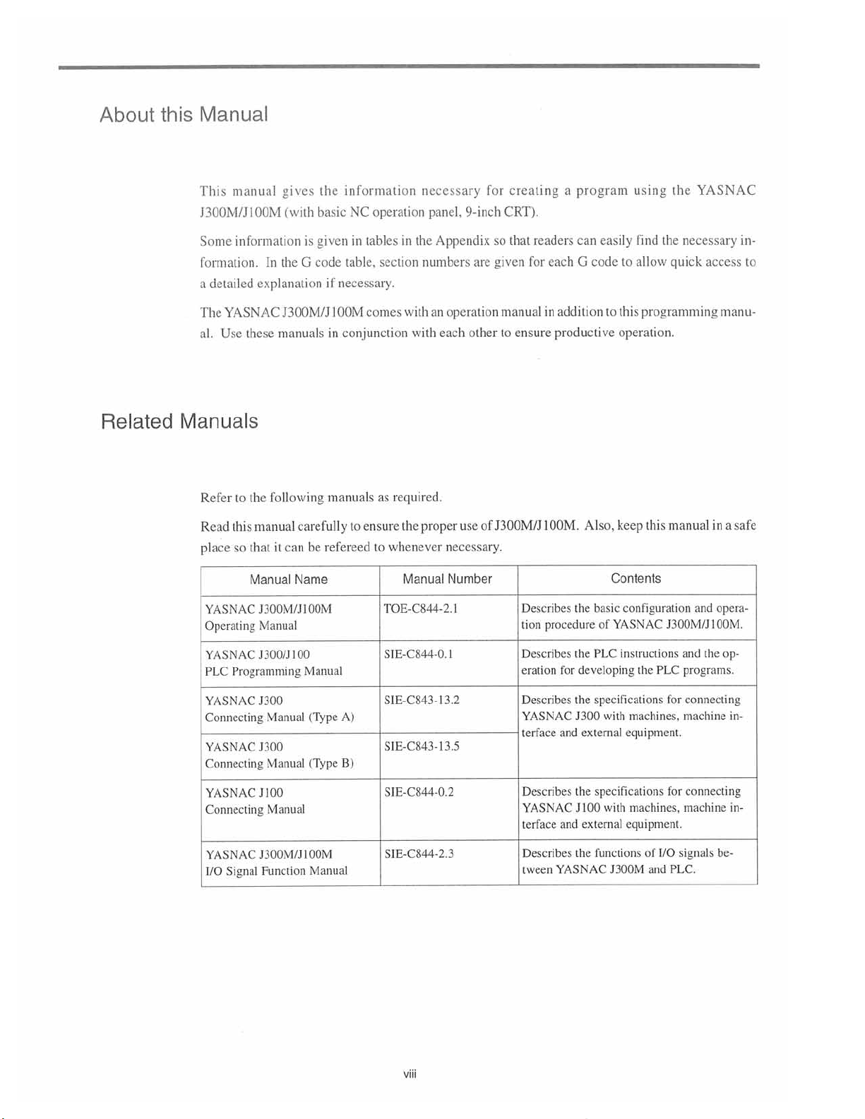
Refer
to
Read
this
so
place
gives
(with
the
In
explanation
J300M/J
manuals
these
following
the
manual
can
that
it
Manual
the
basic
given
is
G
code
if
100M
in
manuals
carefully
be
refereed
Name
information
operation
NC
tables
in
table,
section
necessary.
comes
conjunction
as
ensure
to
whenever
to
necessary
panel,
the
in
numbers
with
an
with
required.
proper
the
Manual
9-inch
Appendix
are
operation
each
other
of
use
necessary.
Number
readers
each
for
a
for
so
given
creating
CRT).
that
manualinaddition
to
ensure
productive
J300M/J100M.
program
easily
can
G
codetoallow
this
to
operation.
Also,
keep
Contents
using
the
find
necessary
the
quick
programming
this
manual
YASNAC
in¬
access
to
manu¬
a
in
safe
YASNAC
Operating
YASNAC
PLC
Programming
YASNAC
Connecting
YASNAC
Connecting
YASNAC
Connecting
YASNAC
Signal
I/O
J300M/JI00M
Manual
100
J300/J
Manual
J300
(Type
Manual
J300
(Type
Manual
J
100
Manual
J300M/J100M
Function
Manual
A)
B)
TOE-C844-2.
S1E-C844-0.
S1E-C843-I3.2
SIE-C843-13.5
SIE-C844-0.2
S1E-C844-2.3
1
the
basic
1
Describes
tion
procedure
Describes
for
eration
Describes
YASNAC
terface
and
Describes
YASNAC
and
terface
Describes
YASNAC
tween
the
developing
the
J300
the
J
the
configuration
YASNAC
of
PLC
instructions
specifications
machines,
with
external
1
external
equipment.
specifications
machines,
00
with
equipment.
functions
J300M
J300M/J100M.
PLC
the
for
for
I/O
of
PLC.
and
and
and
the
programs.
connecting
machine
connecting
machine
signals
opera¬
op¬
in¬
in¬
be¬
viii
Page 9
CAUTIONS
This
manual
be
available
not
to
otherwise
Metric
:
:
the
Zero
Reference
refer
Unless
gramming
•
•
•
Yaskawa
accurately
as
tions
is
and
it
unless
it
performed.
Also
bear
NC
by
the
and
panel
by
lished
describes
with
specification
examples.
for
system
point
has
made
possible
not
specifically
is
mind
in
unit.
The
other
machine
machine
the
the
all
your
YASNAC
document
specified,
input
the
base
in
point
every
effort
possible.
as
describe
to
stated
the
that
performance
entire
related
tool
option
following
the
and
metric
coordinate
to
However,
that
control
equipment
builder
functions
J300M.
or
manuals
system
describe
these.
of
all
something
and
system
for
detailed
(identified
To
determine
published
conditions
for
output/movement
system
individual
are
there
functions
consistsofthe
many
Accordingly,
can
be
performed,
of
addition
in
information
by
the
the
by
the
apply
in
functions
things
readers
NC
an
mechanical
NC.
the
to
relating
symbol)
“*"
option
functions
machine
programming
and
their
that
cannot
are
requested
should
it
machine
be
tool
system,
Therefore,
the
to
but
some
installed
tool
builder.
explanations
relationships
or
must
not
to
assumed
are
determined
not
the
machine
read
the
machine.
these
of
your
in
and
other
to
be
performed
understand
cannot
that
it
operation
manuals
may
NC,
pro¬
func¬
that
be
solely
pub¬
ix
Page 10
NOTES
FOR
SAFE
OPERATION
Read
the
of
functions
The
Before
tool
concerned.
this
In
KEY
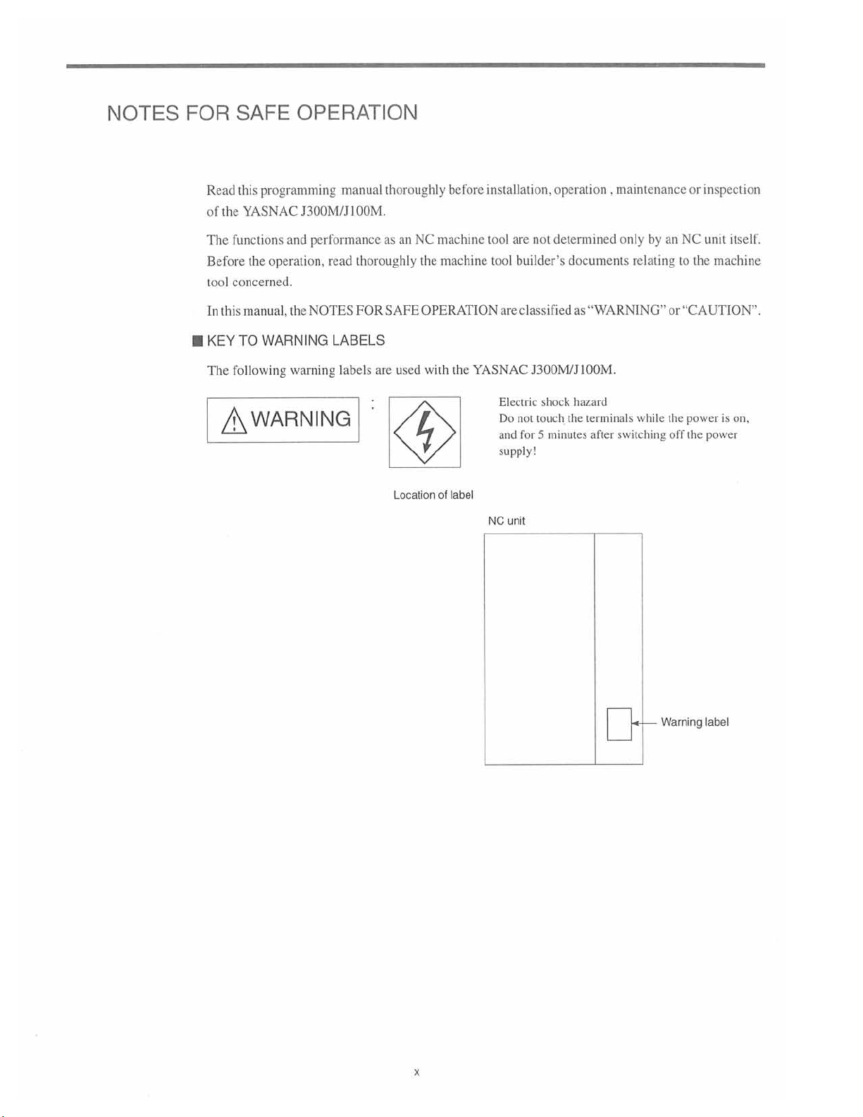
following
The
programming
this
AC
YASN
the
operation,
manual,
WARNING
TO
J300M/J
and
performance
NOTES
the
warning
manual
00M.
1
thoroughly
read
FOR
LABELS
labels
thoroughly
NC
an
as
SAFE
used
are
Location
installation,
before
machine
the
machine
tool
OPERATION
YASNAC
the
with
label
of
NC
tool
are
Electric
Do
and
supply!
unit
are
not
builder’s
classified
J300M/J
shock
touch
not
for
minutes
5
operation
determined
documents
“WARNING”
as
100M.
hazard
the
terminals
after
,
maintenance
by
an
only
relating
while
switching
or
inspection
NC
unit
the
to
machine
or
“CAUTION”.
power
the
off
the
is
power
itself.
on,
Warning
x
label
Page 11
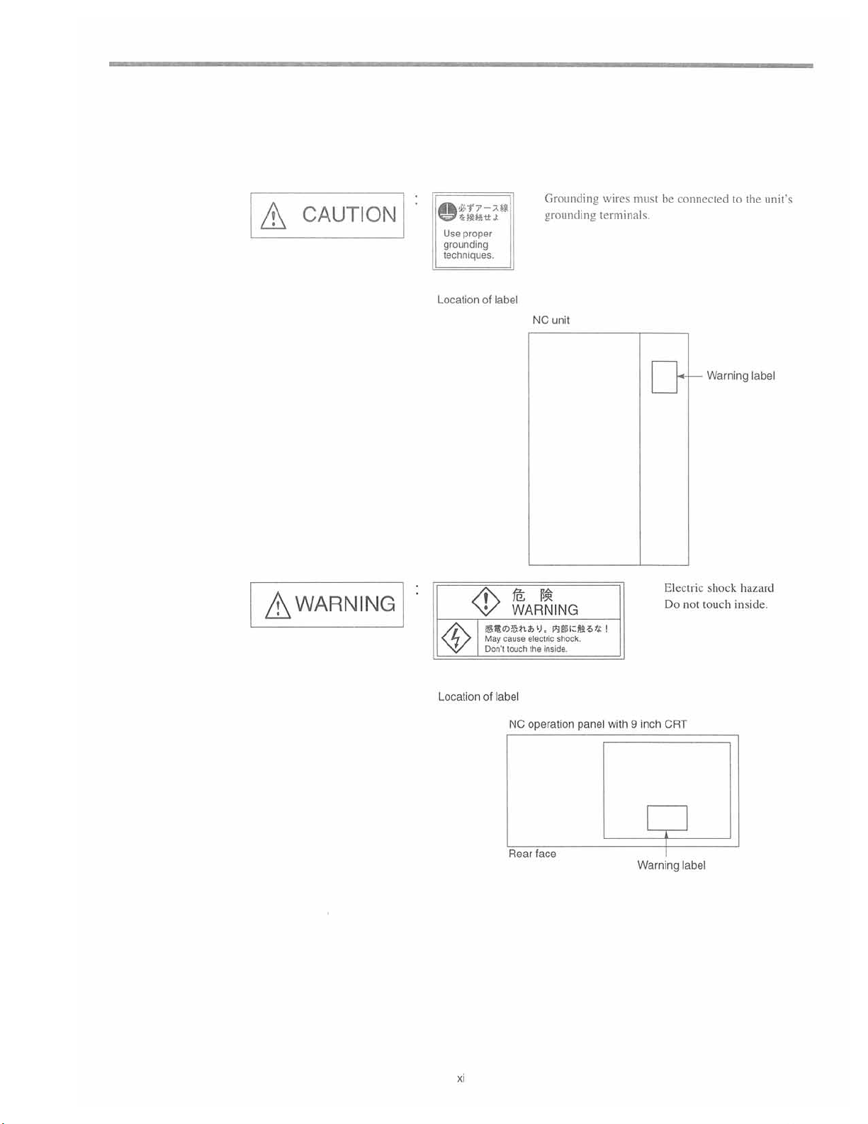
A
CAUTION
&?7-ZH
©
proper
Use
grounding
techniques.
Location
Grounding
grounding
label
of
NC
unit
wires
must
terminals.
be
connectedtothe
unit's
<§>
Location
WARNING
Dsnfcy.
$*<
May
cause
Don't
touch
of
label
NC
1$;
nitcMitti
electric
shock.
the
inside.
operation
panel
with9inch
Electric
Do
not
CRT
Warning
shock
touch
label
hazard
inside.
1
Rear
face
Warning
xi
label
Page 12
General
Precautions
Some
•
describe
ing
this
The
•
and
This
•
tion,
Such
To
order
•
resentative
any
If
•
nameplates
Yaskawa
•
our
drawings
the
detail
product,
figures
and
may
differ
manual
or
may
changes
modification
copy
a
listedonthe
nameplates
of
the
to
not
is
guarantee.
manual
this
in
more
with
operate
and
photographs
the
from
of
your
responsible
product
modified
be
specifications.
in
made
is
manual,
this
Yaskawa
are
clarity.
it
in
this
in
actually
when
as
revision
a
if
your
page
last
to
affixed
representative.
any
for
shown
with
sure
Make
accordance
manual
show
delivered
necessary
renewing
by
copy
has
the
stating
product
the
modification
protective
the
covers
all
with
the
a
representative
to
because
been
manual
become
of
the
cover
shields
and
directionsinthe
you.
improvement
of
the
manual
damaged
No.
product
on
the
damaged
made
or
or
shields
are
product
No.
lost,
contact
front
illegible,
or
by
replaced
manual.
for
of
page.
user
the
removed,
reference
the
product,
your
please
since
in
before
purposes
modifica¬
Yaskawa
send
will
that
order
operat¬
rep¬
these
void
to
xii
Page 13
1
1
PROGRAMMING
Chapter
and
1.1
1
the
describes
feed
functions.
the
basic
FUNDAMENTALS
TERMINOLOGY
1.1.1
.1
.2
1
1.1.3
1.1.4
1.1.5
1.1.6
Numerically
Simultaneously
of
Least
Increment
Maximum
Movement
Tape
Program
Optional
Controlled
Input
Increment
Programmable
Format
Format
Block
terms
OF
PROGRAMMING
Axes
Controllable
and
Least
Values
),
(/1
(/2to/9)
Skip
BASICS
used
and
programming
in
the
Number
Axes
Output
for
Axis
*
1
-2
-2
1
-7
1
-9
1
1
10
-
1
-13
1
-24
.2
1
1.1.7
Buffer
BASICS
1.2.1
1.2.2
1.2.3
.2.4
1
.2.5
1
1.2.6
Rapid
Cutting
F1
Feed
Solid
Automatic
1
OF
-Digit
-1
Register
FEED
Traverse
Feed
Feed*
per
Minute
Tap
Mode
Acceleration
and
Multi-active
FUNCTION
Command)
(F
Function
(G93,
G94)
and
Register
(G94)
*
..
Deceleration
...
..
1
.
1-25
-26
-26
1
-27
1
-31
1
-32
1
-33
1
1-34
Page 14
OF
.1
1
FUNDAMENTALS
PROGRAMMING
TERMINOLOGY
1
basic
section
This
.1
1
Numerically
.1
describes
Controlled
the
Axes
and
terms
the
used
in
Number
programming.
of
Simultaneously
Controllable
Axes
Names
Axes
Numerically
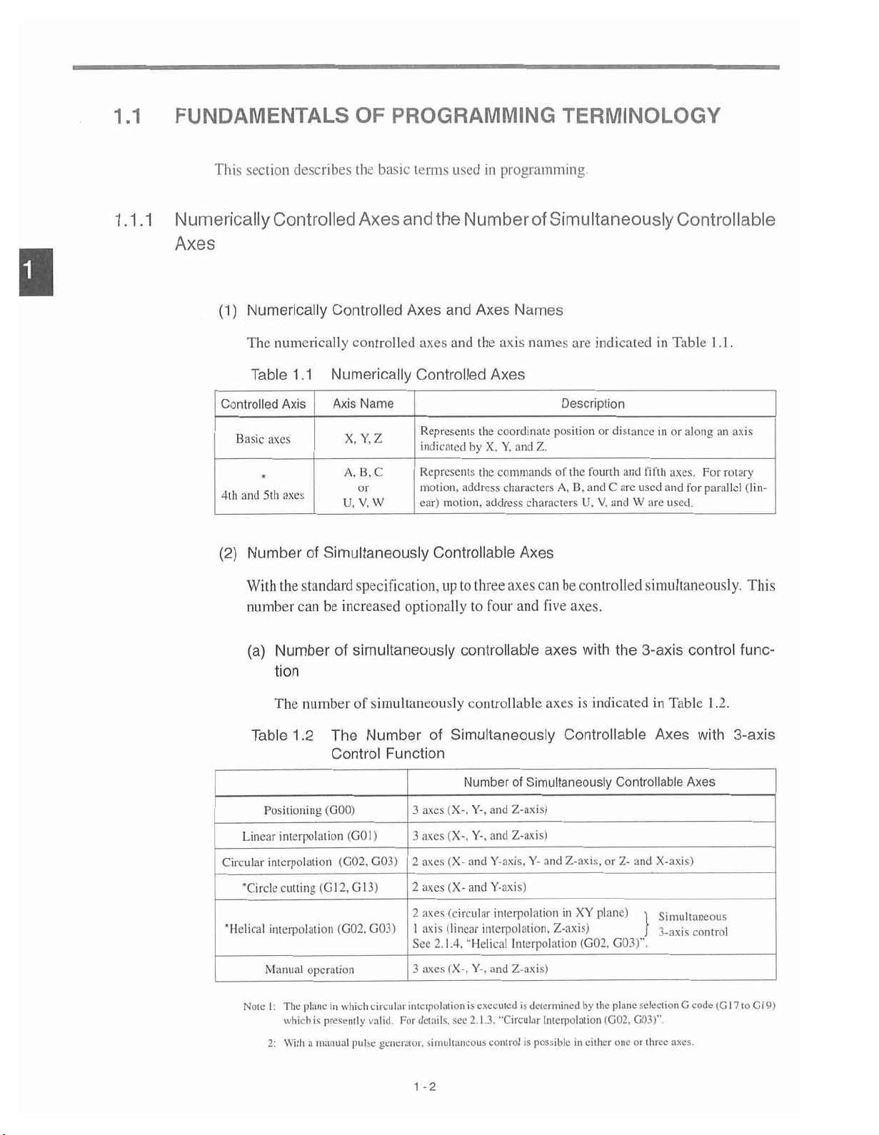
(1)
The
Table
Controlled
Basic
and
5th
4th
(2)
Number
numerically
1.1
Axis Axis
axes
axes
Simultaneously
of
Controlled
controlled
Numerically
Name
Y.Z
X.
A.
B.C
or
W
V.
U.
and
Axes
axes
and
Controlled
Represents
indicated
Represents
motion,
ear)
motion,
Controllable
the
Axes
the
by
X.
the
address
address
names
axis
coordinate
Y,
Z.
and
commands
characters
characters
Axes
are
indicated
Description
position
or
fourth
of
the
and
B.
A.
V.
U.
distance
and
C
are
used
W
and
in
fifth
are
in
and
Table
along
or
axes.
for
used.
1.1.
an
For
rotary
parallel
axis
(lin¬
With
number
(a)
Table
Linear
Circular
'Circle
'Helical
the
standard
can
Number
tion
The
number
1.2
Positioning
interpolation
interpolation
cutting
interpolation
operation
Manual
specification,
increased
be
simultaneously
of
simultaneously
of
Number
The
Control
(GOO)
(G01
G03)
(G02,
GI3)
(G12,
G03)
(G02,
optionally
Function
)
to
up
controllable
Simultaneously
of
(X-.
axes
3
(X-.
axes
3
(X-
axes
2
(X-
axes
2
(circular
axes
2
(linear
axis
1
2.1.4,
See
(X-.
3
axes
axes
three
four
and
to
controllable
Number
and
and
"Helical
of
Z-axis)
and
Y-.
Z-axis)
and
Y-.
Y-axis.
Y-axis)
interpolation
interpolation,
Interpolation
Z-axis)
and
Y-.
can
controlled
be
axes.
five
axes
with
is
axes
indicated
Controllable
Simultaneously
Z-axis,
and
Y-
plane)
in
XY
Z-axis)
(G02,
simultaneously.
3-axis
the
Controllable
or
and
Z-
1
G03)’\
control
Table
in
Axes
X-axis)
Simultaneous
3-axis
1
with
Axes
control
This
func¬
.2.
3-axis
Note
I
2:
:
The
which
With
plane
is
manual
a
which
in
presently
pulse
circular
valid.
generator,
interpolation
details,
For
simultaneous
1
-2
executedisdetermined
is
2.1.3.
"Circular
control
is
see
Interpolation
in
possible
by
the
either
plane
(G02,
one
selection
G03)"
or
three
G
axes.
code
(Ci
9)
G
7
to
1
1
Page 15
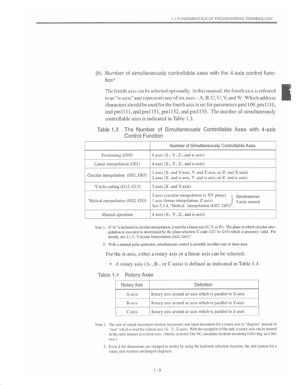
(b)
Number
tion*
simultaneously
of
FUNDAMENTALS
1.1
controllable
axes
OF
PROGRAMMING
with
the
4-axis
TERMINOLOGY
control
func¬
Table
Linear
Circular
"Circle
"Helical
Note
The
fourth
toas“ct-axis”
characters
1
pml
and
controllable
.3
1
(G12,
operation
includedincircular
“a"
is
If
is
polation
details,
see
manual
a
With
(GOO)
Positioning
interpolation
interpolation
cutting
interpolation
Manual
:
I
2:
can
axis
and
should
1,
and
1
axes
The
Number
Control
(G01)
(G02,
G03)
G13)
G03)
(G02,
executed
2.1.3,
"Circular
pulse
be
selected
represents
be used
15
pml
is
indicated
Function
4
4
2
2
2
2
1
See
4
interpolation,
determined
is
Interpolation
generator,
optionally.
any
of
fourth
for
the
1,
152,
pml
Table
in
Simultaneously
of
Number
(X-,
axes
axes
axes
axes
axes
axes
axis
axes
simultaneous
(X-,
(X-
(X-
(X-
(circular
(linear
2.1.4.
(X-,
by
Y-.
Y-.
and
and
and
“Helical
Y-,
it
the
plane
(G02,
must
In
-A,
axes
six
is
axis
pml
and
1.3.
Simultaneously
of
a-axis)
and
Z-.
a-axis)
and
Z-.
Y-axis,
Y-
a-axis,
Y-
Y-axis)
interpolation
interpolation,
Interpolation
Z-,
a-axis)
and
linear
be
a
selectionGcode
G03)’\
control
possible
is
manual,
this
B.C,
for
set
parameters
The
153.
Controllable
and
Z-axis.
a-axis,
and
in
XY
Z-axis)
(G02,
V,
(U,
axis
(GI7
cither
in
the
U,
V,
number
Controllable
or
and
Z-
or
and
Z-
plane)
G03)“.
W).
The
or
G19)
to
one
or
fourth
W.
and
pm
of
Axes
X-axis)
a-axis)
Simultaneous
i
3-axis
plane
in
is
which
axes.
three
referred
axis
is
Which
1
address
09,
1
pml
11
0,
simultaneously
with
4-axis
Axes
control
circular
valid.
inter¬
For
which
presently
I
Table
Note
l
2:
For
:
The
"mm"
in
Even
rotary
•
mm.)
the
rotary
A
1.4
Rotary
unit
whichisused
same
the
the
if
axis
a-axis,
Rotary
A-axis
B-axis
C-axis
output
of
manner
dimensions
remains
either
axis
Axes
Axis
increment
for
as
unchanged
(A-,
a
linear
a
are
linear
rotary
a
B-,
or
Rotary
axis
Rotary
axis
axis
Rotary
(motion
(X-.
axis
axis.(Metric
changed
to
(degrees).
-3
1
or
axis
C-axis)
around
around
aroundanaxis
increment)
Z-axis).
Y-.
system)
by
inches
linear
a
is
defined
axis
an
axis
an
and
input
With
(The
using
axis
as
Definition
which
which
which
increment
exception
the
calculates
NC
the
inch/mm
can
be
selected.
indicatedinTable
is
parallel
is
parallel
parallel
is
for
selection
feedrate
X-axis
to
Y-axis
to
Z-axis
to
axis
unit,
a
assuming
function,
is
rotary
a
rotary
of
the
.4.
1
"degrees"
can
axis
1
0.00
the
unit
instead
be
deg.
system
treated
as
0.001
for
of
a
Page 16
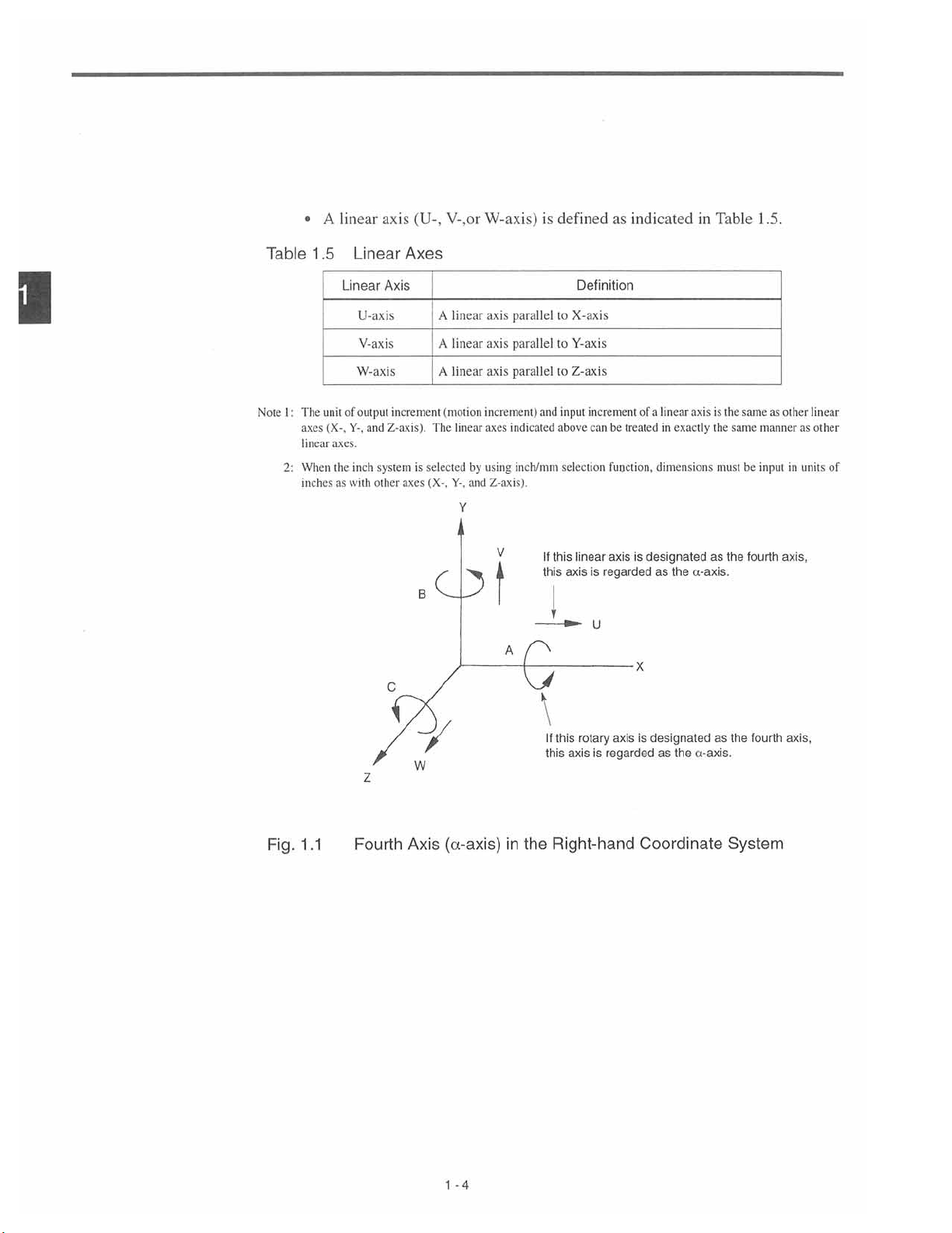
•
A
linear
axis
(U-,
V-,or
W-axis)
defined
is
as
indicatedinTable
1
.5.
1
Table
Note
I:
2:
1.5
The
axes
linear
When
inches
.
unit
(X-.
Linear
of
axes.
the
as
Linear
U-axis
V-axis
W-axis
output
Y-,
and
system
inch
with
other
Axes
Axis
increment
Z-axis).
is
axes
C
linear
A
linear
A
linear
A
(motion
The
linear
selected
(X-.
Y-.
B
Of
Y
axis
axis
axis
increment)
axes
by
using
Z-axis).
and
parallel
parallel
parallel
indicated
inch/mm
V
A
and
If
this
T
k
Definition
to
X-axis
Y-axis
to
Z-axis
to
input
above
selection
linear
this
axis
increment
can
be
treated
function,
axis
regarded
is
U
linear
a
of
in
dimensions
designated
is
as
axisisthe
exactly
the
a-axis.
as
the
must
same
the
same
be
fourth
as
other
manner
inpul
axis.
linear
other
as
of
units
in
Fig.
1.1
Z
Fourth
W
Axis
(a-axis)
-4
1
in
the
II
rotary
this
this
axis
regarded
is
Right-hand
designated
is
axis
Coordinate
as
the
as
a-axis.
fourth
the
System
axis,
Page 17
.1
FUNDAMENTALS
1
OF
PROGRAMMING
TERMINOLOGY
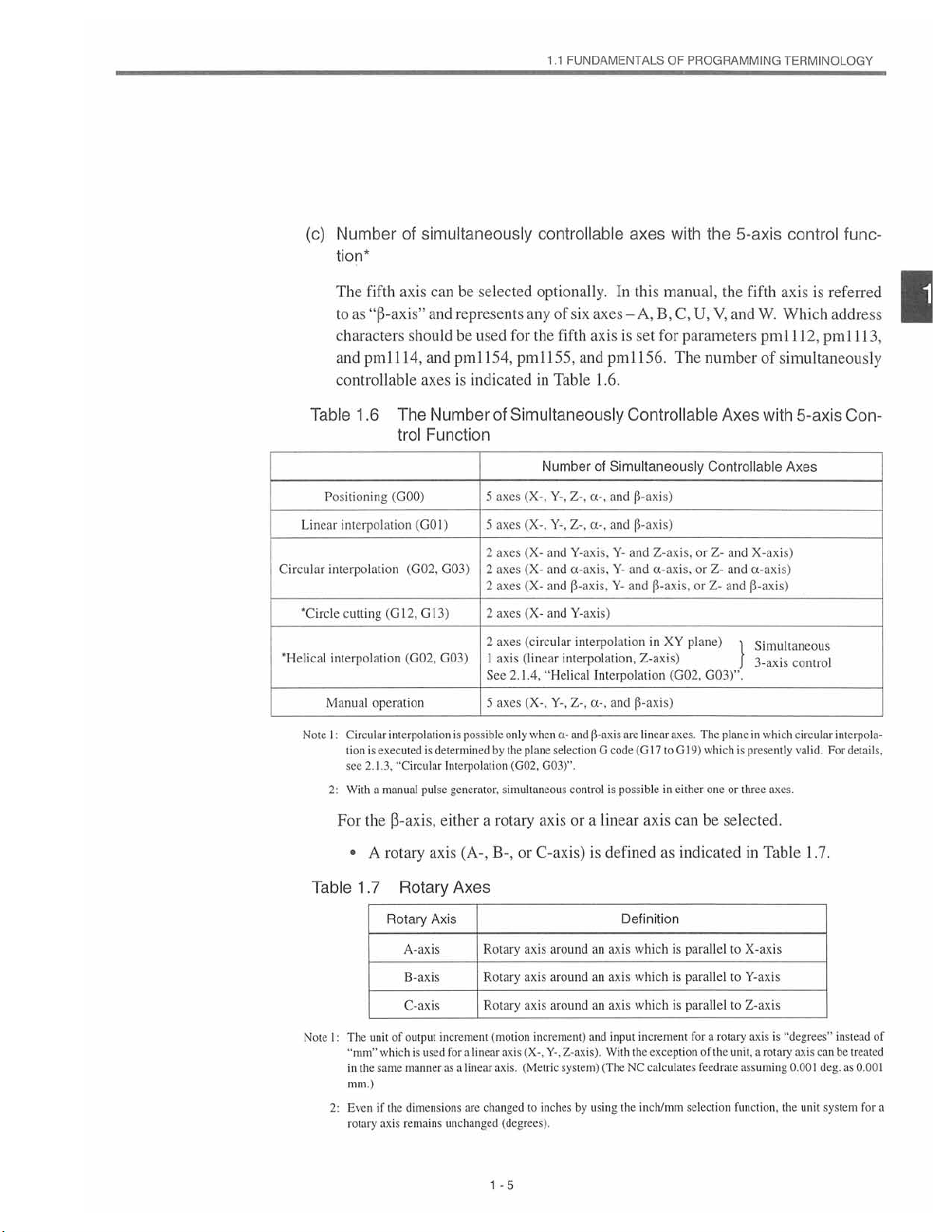
(c)
Table
Linear
Circular
'Circle
'Helical
Number
tion*
The
fifth
“(3-axis”
as
to
characters
and
pml
controllable
.6
1
Positioning
interpolation
interpolation
(G
culling
interpolation
Manual
operation
simultaneously
of
can
axis
and
be
represents
shouldbeused
14,
and
1
The
trol
(GOO)
(G02,
2,
1
(G02,
pml
axes
is
Number
Function
(GOI)
G03)
3)
G
1
G03)
selected
any
for
154,
pml
indicated
of
Simultaneously
(X-,
axes
5
(X-.
axes
5
(X-
2
axes
(X-
axes
2
(X-
axes
2
(X-
axes
2
(circular
axes
2
(linear
1
axis
2.1.4,
Sec
(X-.
axes
5
controllable
optionally.
of
axes
six
the
in
axis
fifth
155,
and
Table
Number
a-,
Z-,
Y-.
a-,
Z-,
Y-.
Y-axis,
and
a-axis,
and
(3-axis.
and
Y-axis)
and
interpolation
interpolation,
"Helical
a-,
Z-,
Y-,
1
of
Interpolation
axes
with
manual,
this
In
C,
B,
A,
-
for
is
set
pml
156.
The
.6.
Controllable
Simultaneously
(5-axis)
and
and
(3-axis)
Z-axis,
and
Y-
ct-axis,
Y-
and
(3-axis,
Y-
and
XY
in
Z-axis)
(G02.
(3-axis)
and
the
5-axis
the
U,
V,
and
parameters
number
Axes
Controllable
or
Z-
and
or
Z-
and
or
Z-
and
plane)
!
G03)”.
control
axis
fifth
W.
Which
pm
111
of
simultaneously
with
5-axis
Axes
X-axis)
a-axis)
(3-axis)
Simultaneous
3-axis
control
is
referred
2,
pml
func¬
address
3,
1
1
Con¬
1
Note
Table
Note
:
I
2:
1
2:
For
:
interpolationispossible
Circular
is
executed
tion
see
With
•
2.1.3.
the
.7
1
manual
a
(3-axis,
rotary
A
“Circular
Rotary
Rotary
A-axis
B-axis
C-axis
of
unit
the
which
same
(he
if
axis
output
manner
dimensions
remains
The
"mm”
in
mm.)
Even
rotary
is
determined
pulse
axis
Axis
is
used
Interpolation
generator,
a
either
(A-,
Axes
Rotary
Rotary
Rotary
increment
for
linear
a
linear
as
a
changed
are
unchanged
only
whena-and
by
the
plane
(G02,
simultaneous
rotary
B-,
or
axis
axis
axis
(motion
increment)
(X-.
axis
(Metric
axis.
to
(degrees).
1
-5
(3-axis
selectionGcode
G03)".
control
axis
or
a
C-axis)
inches
is
around
aroundanaxis
around
and
Z-axis).
Y-.
system)
by
using
axes.
The
are
possible
is
linear
linear
(G17
axis
toGI9)
either
in
can
plane
which
one
or
be
selected.
in
presently
is
three
which
definedasindicatedinTable
Definition
which
an
an
axis
axis
input
With
(The
which
which
increment
the
NC
inch/mm
the
is
is
is
parallel
exception
calculates
parallel
parallel
for
feedrate
selection
X-axis
to
Y-axis
to
Z-axis
to
rotary
axis
a
unit,
of
the
a
assuming
function,
axes.
is
rotary
circular
valid
1.7.
"degrees"
axis
0.001
the
unit
interpola¬
For
instead
can
be
deg.
system
details.
treated
as
0.001
for
of
a
Page 18

•
A
linear
axis
(U-,
V-,
W-axis)
or
is
definedasindicated
in
Table
1.8.
1
Table
Note
I
2:
:
.8
1
The
axes
linear
When
inches
unit
(X-.
axes.
Linear
of
Y-.
the
as
with
Linear
Axis
U-axis
V-axis
W-axis
output
and
system
inch
other
Axes
increment
Z-axis).
is
axes
B
C
linear
A
linear
A
linear
A
(motion
linear
The
selected
(X-,
Y-.
Of
axis
axis
axis
increment)
axes
by
using
and
indicated
Z-axis).
V
A
parallel
parallel
parallel
and
inch/mm
If
this
Definition
X-axis
to
to
Y-axis
Z-axis
to
input
above
selection
this
linear
axis
increment
be
treated
can
function,
axis
regarded
is
U
of
a
linear
in
dimensions
designated
is
as
axisisthe
exactly
|5-axis.
the
as
the
must
same
the
same
be
fifth
as
other
manner
input
axis.
linear
as
other
of
units
in
Fig.
\
the
as
p-axis.
System
rotary
this
If
this
Right-hand
the
Axis
W
((3-axis)
in
Z
Fifth
.2
1
axis
is
designated
axis
is
regarded
as
Coordinate
the
fifth
axis,
-6
1
Page 19
.1
1
FUNDAMENTALS
OF
PROGRAMMING
TERMINOLOGY
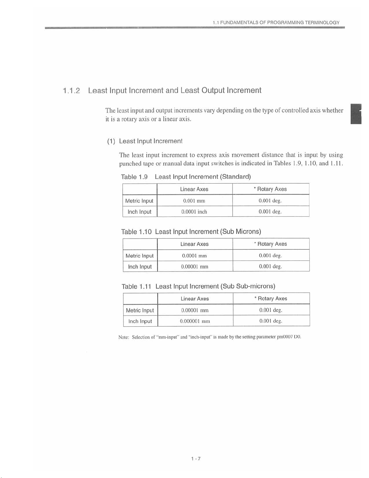
.2
Least
.1
1
Input
The
is
it
(1)
Increment
least
input
a
rotary
Least
least
The
punched
Table
Metric
Inch
Table
Metric
and
axis
Input
input
tape
1.9
Input
Input
1.10
Input
output
or
a
Increment
increment
or
Least
Least
and
increments
linear
manual
Input
Input
Least
axis.
data
Linear
0.001
0.0001
Linear
0.0001
Output
vary
express
to
input
Increment
Axes
mm
inch
Increment
Axes
mm
Increment
on
depending
axis
movement
switchesisindicated
(Standard)
(Sub
the
•
Microns)
*
Rotary
0.001
0.001
Rotary
0.001
of
type
distance
Tables
in
Axes
deg.
deg.
Axes
deg.
controlled
input
is
that
1.9,
1.10,
axis
whether
by
using
and
1.11.
l
Table
Metric
Note:
Input
Inch
1
Input
Inch
Selection
.11
Input
Least
"mm-input"
of
0.00001
Input
Linear
0.00001
0.000001
and
mm
Increment
Axes
mm
mm
“inch-input”
is
(Sub
made
Sub-microns)
*
by
setting
the
0.001
Rotary
0.001
0.001
parameter
deg.
Axes
deg.
deg.
pm0007
DO.
-7
1
Page 20
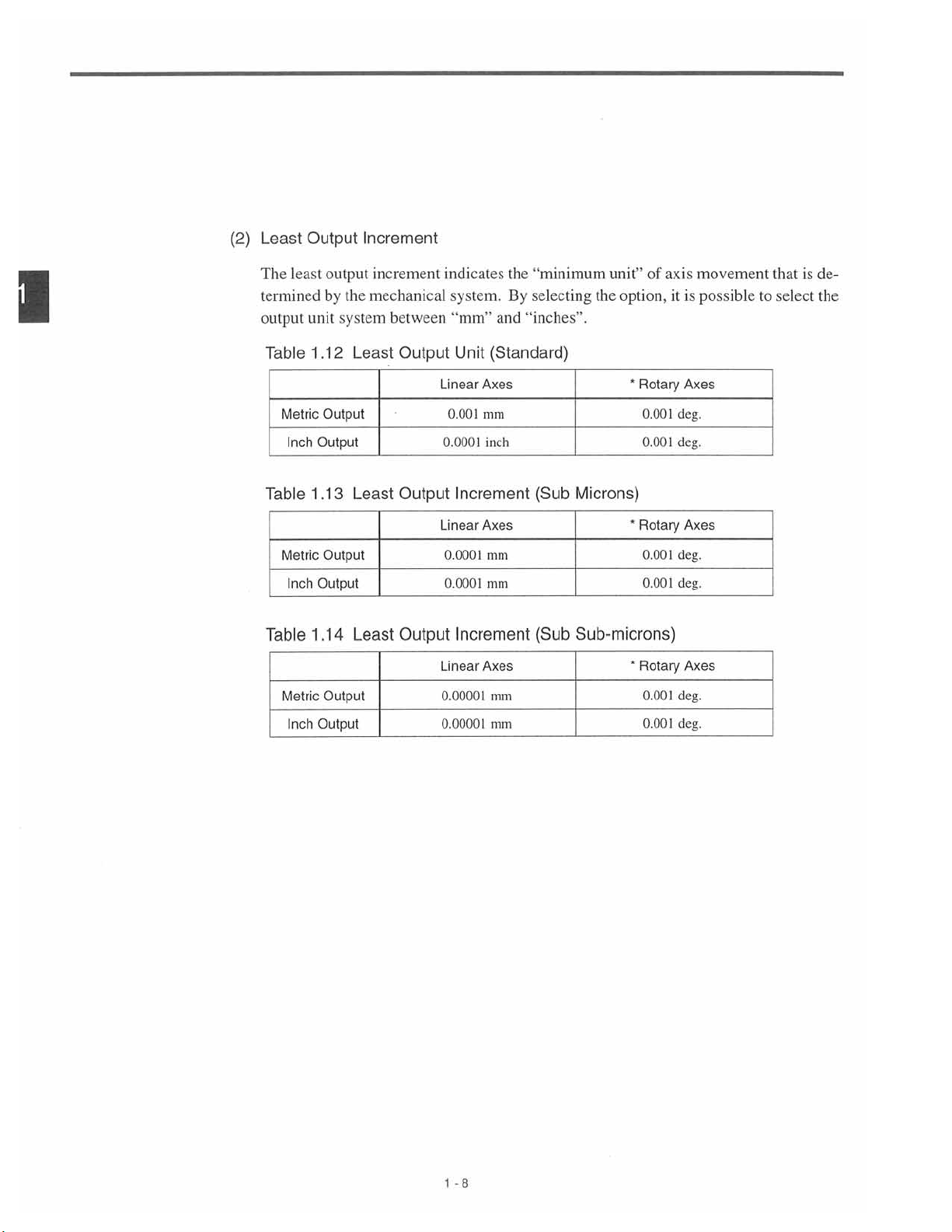
(2)
Least
Output
Increment
1
The
least
termined
output
unit
Table
Metric
Inch
Table
Metric
Inch
Table
Metric
Inch
output
by
1.12
Output
Output
1.13
Output
Output
1.14
Output
Output
increment
the
mechanical
system
Least
Least
Least
between
Output
Output
Output
indicates
system.
“mm”
Unit
Axes
Linear
0.001
mm
0.0001
inch
Increment
Axes
Linear
0.0001
mm
mm
0.0001
Increment
Axes
Linear
0.00001
0.00001
the
“minimum
By
selecting
“inches”.
and
(Standard)
(Sub
(Sub
mm
mm
of
unit”
option,
the
'
Rotary
0.001
0.001
Microns)
*
Rotary
0.001
0.001
Sub-microns)
*
Rotary
0.001
0.001
axis
it
deg.
deg.
deg.
deg.
deg.
deg.
is
Axes
Axes
Axes
movement
possible
to
that
select
is
de¬
the
1
-8
Page 21
.1
1
FUNDAMENTALS
OF
PROGRAMMING
TERMINOLOGY
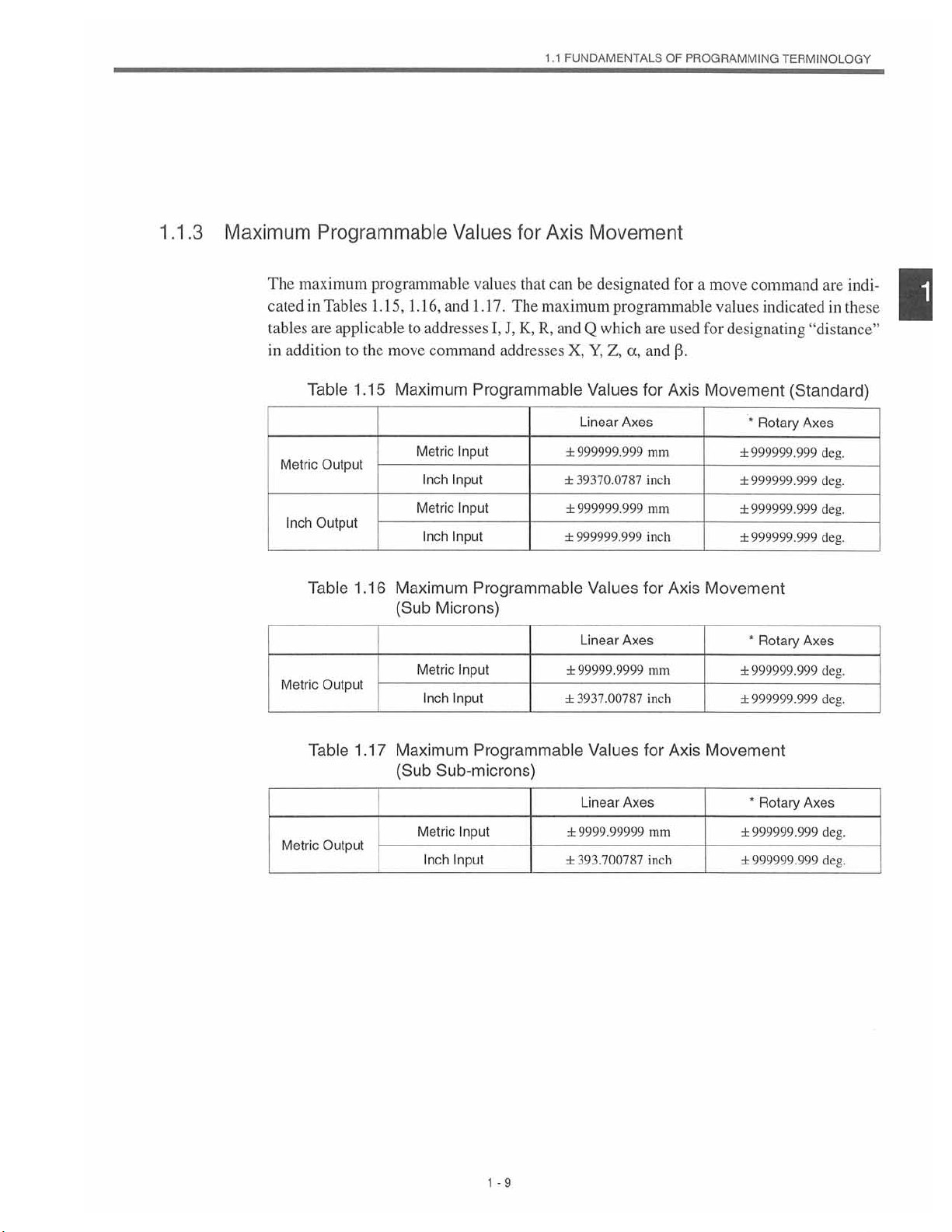
1.1.3
Maximum
The
maximum
cated
tables
addition
in
Metric
Inch
Metric
Programmable
programmable
Tables
in
are
Table
Output
Output
Table
Output
1.15,
applicable
the
move
to
Maximum
1.15
Maximum
1.16
(Sub
1.16,
and
addresses
to
command
Metric
Inch
Metric
Inch
Microns)
Metric
Inch
Values
values
1.17.
I,
The
J,
for
that
K,
addresses
Programmable
Input
Input
Input
Input
Programmable
Input
Input
Axis
Movement
can
be
designated
maximum
R,
Q
and
X,Y,Z,
Values
Linear
±999999.999
39370.0787
±
±999999
±999999.999
Values
Linear
±99999.9999
±3937.00787
for
programmable
are
which
Axes
999
Axes
used
a,
and
Axis
for
mm
inch
mm
inch
for
Axis
mm
inch
a
move
for
(3.
Movement
Movement
command
values
indicated
designating
*
Rotary
±999999.999
±999999.999
±999999.999
999999.999
±
*
Rotary
±999999.999
999999.999
±
are
indi¬
in
these
“distance”
(Standard)
Axes
deg.
deg.
deg.
deg.
Axes
deg.
deg.
1
Table
Metric
1.17
Output
Maximum
Sub-microns)
(Sub
Metric
Input
Inch
Programmable
Input
-9
1
Values
Axes
Linear
±9999.99999
393.700787
±
for
mm
inch
Axis
Movement
*
Rotary
Axes
±999999.999
±999999.999
deg.
deg.
Page 22
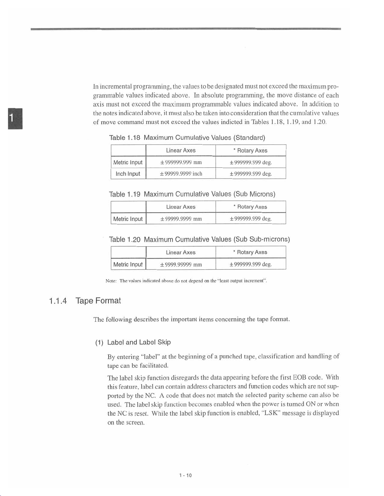
1
incremental
In
grammable
axis
must
notes
move
indicated
command
the
of
programming,
values
exceed
not
indicated
the
maximum
above,
must
it
not
be
the
values
to
designated
above.Inabsolute
programmable
alsobetaken
must
the
exceed
values
not
must
programming,
values
consideration
into
indicated
indictedinTables
exceed
the
move
the
maximum
distance
above.Inaddition
the
that
1.18,
cumulative
1.19,
and
1
.20.
of
pro¬
each
to
values
1.1.4
Tape
Table
Metric
Inch
Table
Metric
Table
Metric
Note:
Format
The
1.18
Input
Input
1.19
Input
.20
1
Input
values
Maximum
Linear
±999999.999
±99999.9999
Maximum
Linear
±99999.9999
Maximum
Linear
±9999.99999
indicaled
above
Cumulative
Axes
mm
inch
Cumulative
Axes
mm
Cumulative
Axes
mm
on
depend
do
not
Values
Values
Values
the
"least
(Standard)
*
Rotary
Axes
±999999.999
±999999.999
Microns)
(Sub
*
Rotary
Axes
±999999.999
(Sub
Sub-microns)
*
Rotary
Axes
±999999.999
increment".
output
deg.
deg.
deg.
deg.
The
(1)
following
Label
and
entering
By
can
tape
label
The
feature,
this
by
ported
The
used.
NC
the
screen.
on
the
describes
Label
“label”
facilitated.
be
skip
label
NC.
the
label
is
reset.
the
Skip
at
function
can
A
function
skip
While
important
beginning
the
disregards
contain
that
code
label
the
1
address
does
becomes
skip
10
-
items
of
the
data
characters
not
function
concerning
a
punched
appearing
match
the
enabled
when
enabled,
is
the
tape,
and
selected
format.
tape
classification
before
the
function
parity
power
the
“LSK”
first
codes
is
message
and
EOB
which
scheme
turned
handling
code.
are
not
can
also
ON
or
displayed
is
of
With
sup¬
be
when
Page 23
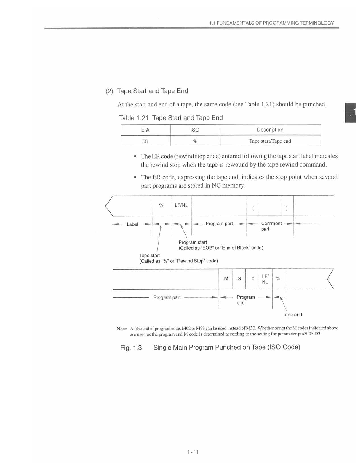
(2)
Tape
Start
and
Tape
End
FUNDAMENTALS
1.1
OF
PROGRAMMING
TERMINOLOGY
the
At
Table
•
•
Label
start
.21
1
The
The
part
Tape
(Called
EIA
ER
the
and
rewind
start
of
end
Tape
Start
code
ER
stop
code,
ER
programs
%
I
as
or
a
tape,
and
iso
%
(rewind
when
expressing
are
stored
LF/NL
"
!
Program
(Called
"Rewind
Stop"
the
Tape
stop
the
start
“EOB"
as
same
End
code)
tape
the
NC
in
Program
or
code)
(see
code
entered
is
rewound
end,
tape
memory.
part
"EndofBlock”
Table
1
Description
Tape
start/Tape
following
the
by
indicates
(
Comment
part
code)
.2
the
1)
the
tape
should
end
tape
rewind
stop
)
be
start
command.
point
punched.
label
indicates
when
I
several
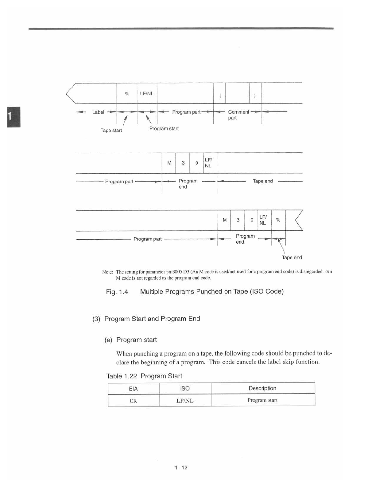
Note:
Fig.
As
are
the
1.3
used
end
of
as
the
Program
program
program
Single
part
code.
end
Main
can
M99
or
M02
codeisdetermined
M
Program
M
used
instead
be
according
Punched
3
I
Program
end
of
to
on
0
M30.
the
Tape
LF/
NL
Whether
setting
(ISO
%
or
for
Tape
theMcodes
not
parameter
Code)
end
pm3005
indicated
D3.
above
1
-11
Page 24
LF/NL
%
(
)
1
Label
Tape
Program
Note:
start
The
M
/
part
setting
code
Program
for
is
not
\
Program
part
parameter
regarded
start
M
pm3005
the
as
Program
3
Program
end
D3
program
part
(
An
end
0
M
code.
ILF/
NL
is
code
Comment
part
M
used/not
3
Program
end
for
used
Tape
0
a
end
LF/
NL
program
%
end
Tape
code)
end
disregarded
is
An
(3)
1
Fig.
.4
Program
Program
(a)
When
clare
1
Table
Multiple
Start
punching
beginning
the
Program
.22
EIA
CR
and
start
Programs
Program
a
program
of
a
Start
LF/NL
1
Punched
End
on
a
program.
ISO
12
-
tape,
the
This
Tape
on
following
cancels
code
Code)
(ISO
.should
code
the
label
Description
Program
start
be
skip
punched
function.
de¬
to
Page 25
1
FUNDAMENTALS
.1
OF
PROGRAMMING
TERMINOLOGY
1.1.5
Program
Program
(b)
Any
of
Table
:
I
Note
2:
3:
Format
of
a
program
1.23
ElA
M02CR
M30CR
M99CR
When
on
equipment
Refer
When
reading
occurs
This
ER
If
gram;
end
the
Program
"M02CR”
manual
the
to
multiple
program
the
when
or
LF/NL
NC
the
following
declare
to
End
or
"M30LF/NL"
specifications.
published
programs
part
code
end
programs
part
is
executed
code
is
reset.
indicatedinTable
codes
program
the
iso
M02LF/NL
M30LF/NL
M99LF/NL
executed,
is
by
the
machine
are
started
shown
above.
are
enteredbytotal
a
program
for
1.23
should
end.
Description
Program
Program
Subprogram
input.
control
neither
mayormay
may
nor
M02
the
equipment
tool
builder.
memory,
NC
the
in
which
in
end
move
M30
be
punched
end
and
rewind
end
notbereset
the
to
is
enteredatthe
or
next
at
rewound
program
part
end
the
end
depending
after
pro¬
of
the
1
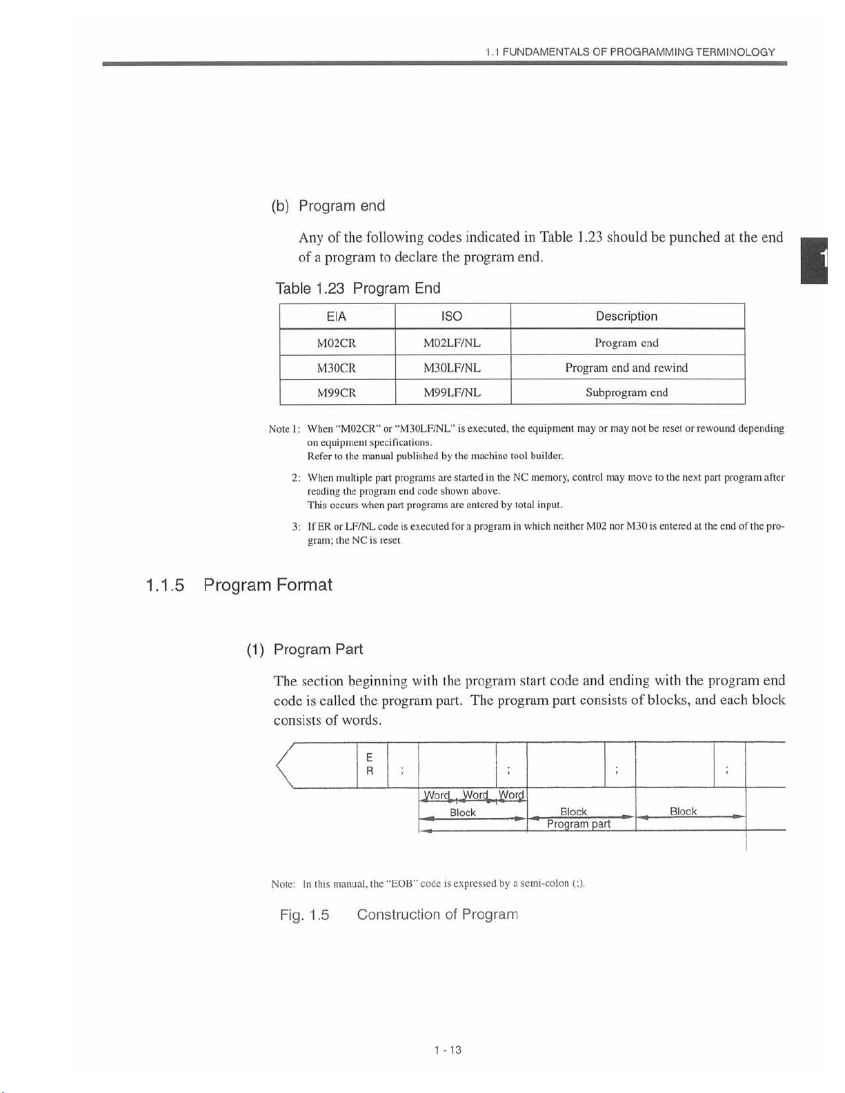
(1)
Program
section
The
is
code
consists
Note;
In
1.5
Fig.
called
of
manual,
this
Part
beginning
the
program
words.
E
R
"EOB”
the
Construction
with
Word
code
the
part.
is
of
1
-
13
program
The
Wortÿ
]
_
Block
expressed
Program
start
program
Word
by
semi-colon
a
code
part
Block
Program
(;).
and
ending
consists
part
of
with
blocks,
Block
the
and
program
each
end
block
Page 26
(a)
Program
number
1
(SUPPLE/-ÿ
IMENT
(b)
.
1
entering
By
sible
consists
NC
The
can
be
Sequence
sequence
A
follows
are
used
execution
numbers
without
assigned
be
quence
order.
program
search
sequence
If
a
the
least
a
program
distinguish
to
of
addressOandamaximum
memory
optionally
number
a
specific
has
capacity
a
increased
number
number,
address
for
only
order
may
assigning
to
numbers,
Before
number
shouldbeexecuted.
number
insignificant
consisting
N,
can
reference
machining
of
be
used
sequence
different
is
it
executing
search
consisting
digit
be
for
blocks.
recommended
the
immediately
program
to
to
storeupto
of
enteredatthe
numbersofblocks
from
of
store
a
addressNand
beginning
processes.
sequence
numbers.
sequence
determine
to
regarded
are
numbers.
Although
of6of
addition,
In
to
assign
number
the
more
as
after
the
program
other
programs.Aprogram
5-digit
maximum
299or999
Therefore,
and
there
number
of
programs.
maximum
a
of
a
do
not
sequential
is
also
It
same
the
are
no
99
block.
sequence
search,
program
digitsisdesignated,5digits
a
sequence
it
in
number.
start
that
follows
programs;
5-digit
of
Sequence
influence
allowed
sequence
restrictions
numbers
is
necessary
which
sequence
or
code,
is
pos¬
it
number
address
this
capacity
integer
that
numbers
the
contents
and
non-sequential
leave
to
in
to
blocks
number
using
on
a
sequential
execute
may
number
from
O.
se¬
the
2.
3.
4.
address
If
one
than
that
at
For
blocks
the
address
as
nated
designating
When
number.
search
block,
block.
for
search
the
the
which
object
is
executed
block
searched
a
sequence
operation
of
address
sequence
a
1
-
14
for
address
if
search
number
sequence
a
is
first
number
datainthe
operation.
following
read
is
number
and
search
assigned,
not
blocktobe
G25
which
processing
search
M99,
or
assigned
is
is
is
searched
designate
more
to
completed
possible
desig¬
are
4-digit
a
by
Page 27
(c)
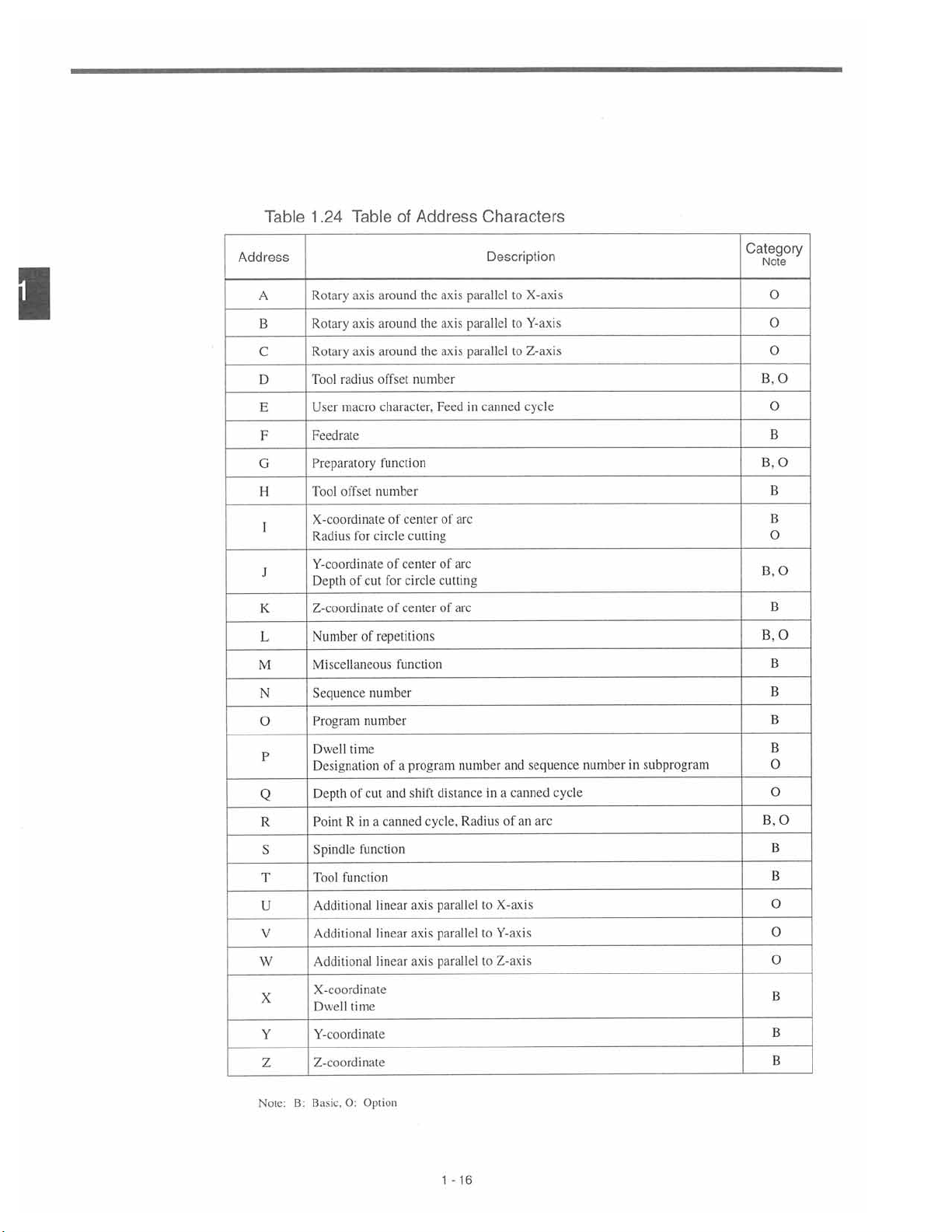
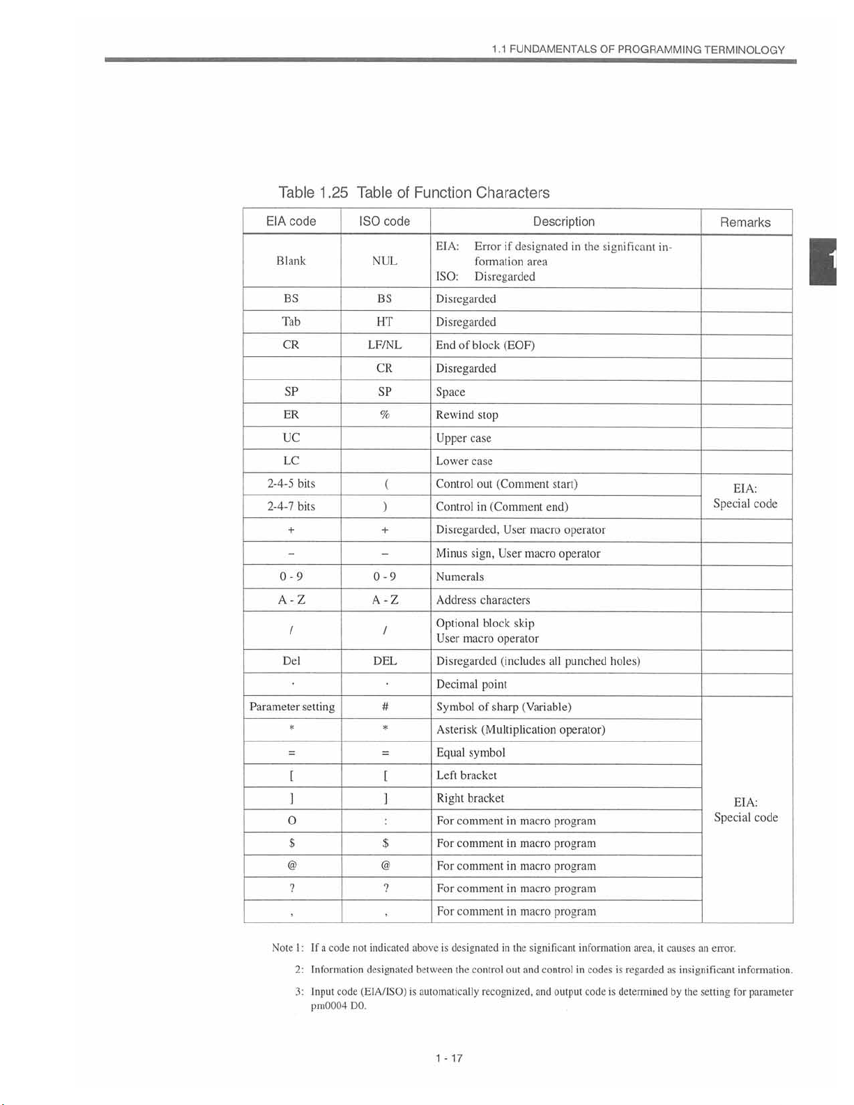
Word
1.1
FUNDAMENTALS
OF
PROGRAMMING
TERMINOLOGY
word
A
numeral
“G02”
The
function
For
area.
and
1.24
consists
of
several
consists
details
1.25.
of
an
digits
of
address
character
of
address
address
that
character
means
character
character
follow
“G”
character
a
and
includedinthe
the
address
and
numeral
that
can
function
function
character.
“2”.
be
used
character
For
in
the
codes,
characters
example,
significant
refer
to
and
word
data
Tables
a
1
15
1
-
Page 28
Table
TableofAddress
.24
1
Characters
1
Address
A
B
C
D
E
F
G
H
I
J
K
L
M
N
O
Rotary
Rotary
Rotary
Tool
User
Feedrate
Preparatory
Tool
X-coordinate
Radius
axis
axis
axis
radius
macro
offset
for
around
around
around
offset
character.
function
number
circle
Y-coordinate
of
Depth
Z-coordinate
Number
cut
of
repetitions
Miscellaneous
Sequence
Program
number
number
of
center
cutting
of
center
for
circle
of
center
function
axis
the
the
axis
the
axis
number
Feedincanned
arc
of
of
arc
cutting
arc
of
Description
parallel
parallel
parallel
to
to
to
X-axis
Y-axis
Z-axis
cycle
Category
Note
O
O
O
O
B.
O
B
O
B.
B
B
O
B.O
B
B,
O
B
B
B
P
Q
R
S
T
U
V
W
X
Y
Z
Note:
Dwell
Designation
Depth
Point
Spindle
Tool
Additional
Additional
Additional
X-coordinate
Dwell
Y-coordinate
Z-eoordinale
B:
Basic.
time
cut
of
a
in
R
function
function
linear
linear
time
0:
Option
of
and
canned
linear
program
a
shift
cycle,
axis
axis
axis
number
distance
Radius
parallel
parallel
parallel
16
1
-
in
to
to
to
and
canned
a
of
an
X-axis
Y-axis
Z-axis
sequence
cycle
arc
number
subprogram
in
B
O
O
B.O
B
B
O
O
O
B
B
B
Page 29
1.1
FUNDAMENTALS
OF
PROGRAMMING
TERMINOLOGY
Table
code
EIA
Blank
BS
Tab
CR
SP
ER
UC
LC
bits
2-4-5
2-4-7
bits
+
0-9
A-Z
/
Del
Parameter
setting
*
[
I
O
$
@ @
?
Table
ISO
NUL
BS
HT
LF/NL
CR
SP
%
+
0-9
A-Z
DEL
#
*
zr
$
code
(
)
/
[
?
of
Function
Characters
EIA:
Error
formation
ISO:
Disregarded
Disregarded
Disregarded
of
End
block
Disregarded
Space
Rewind
Control
Control
Optional
Symbol
stop
Upper
case
case
Lower
out
in
Disregarded.
sign.
Minus
Numerals
Address
characters
block
User
macro
Disregarded
Decimal
point
of
Asterisk
Equal
Left
Right
For
For
For
For
For
(Multiplication
symbol
bracket
bracket
comment
comment
comment
comment
comment
designated
if
area
(EOF)
(Comment
(Comment
User
User
macro
skip
operator
(includes
(Variable)
sharp
in
macro
macro
in
macro
in
in
macro
macro
in
Description
in
start)
end)
macro
operator
operator
all
punched
operator)
program
program
program
program
program
the
significant
holes)
in¬
Remarks
EIA:
Special
EIA:
Special
1
code
code
1
.25
Note
:
a
If
I
Information
2:
Input
3:
pm0004
code
code
indicated
not
designated
(El
DO.
A/ISO)
designated
above
is
between
automatically
is
1
17
-
the
in
control
recognized,
the
out
significant
and
information
controlincodes
and
output
code
area,
regarded
is
is
determined
it
causes
insignificant
as
by
the
error.
an
setting
information.
for
parameter
Page 30
I
(d)
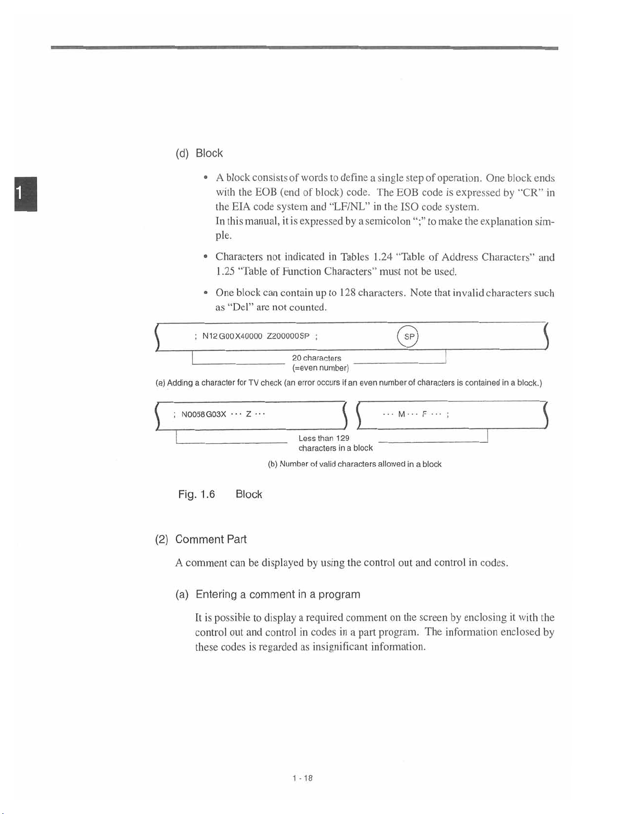
Block
•
A
with
the
In
pie.
block
consistsofwordstodefine
EOB
code
(end
system
is
it
of
expressed
EIA
this
the
manual,
block)
and
code.
“LF/NL”
by
a
single
a
EOB
The
the
in
ISO
semicolon
step
operation.
of
code
code
make
to
is
expressed
system.
the
One
block
by
“CR”
explanation
ends
in
sim-
[
(a)
1
(2)
Adding
•
•
N12G00X40Q00
;
character
a
;
N0058G03X
Fig.
1.6
Comment
Characters
.25
1
One
“Del”
as
••
not
“TableofFunction
can
block
are
Z200000SP
TV
check
for
•
•
•
•
Z
(b)
Block
Part
indicatedinTables
Characters”
contain
counted.
not
20
(=even
(an
error
Numberofvalid
up
;
characters
number)
occurs
Less
than
characters
to
129
in
characters
128
characters.
_
even
an
if
31
a
block
.24
1
must
number
...
allowed
“Table
not
Note
0
of
characters
•••
M
in
a
of
be
•••
F
block
Address
used.
that
invalid
is
;
Characters’’
characters
contained
in
block.)
a
and
such
3
3
comment
A
Entering
(a)
It
control
these
is
possible
codes
can
out
a
and
be
displayed
comment
display
to
controlincodes
regarded
is
1
by
using
program
a
in
a
required
as
insignificant
18
-
the
comment
a
in
part
control
out
on
the
program.
information.
and
screen
The
control
in
by
enclosing
information
codes.
enclosed
it
with
the
by
Page 31

(b)
Entering
The
control
ordinary
the
control
and
out
characters.
out
control
and
in
.
FUNDAMENTALS
1
1
control
can
codes
in
codes
be
enteredinthe
OF
PROGRAMMING
same
TERMINOLOGY
manner
as
entering
(Operation
I
ft
panel
©
©
with
9-inch
Fig.
1
•
•
CRT)
.7
“(”:Press
“)”:Press
±_
\msms]
V
Characters
In
the
the
“IT
Codes
[U]
[V]
(Keys
key
key
that
after
pressing
pressing
after
©
©
can
be
Enclosed
[SHIFT]
the
[SHIFT]
the
Characters
“("
(control
±_
HUN
KT
PWOOt
I
j
j
HHEEimrgp
[Q.LRJEII
0000B
00E00
~3~
by
between
Dark
Line)
Entered
key.
key.
that
out)
Control
can
and
MUM]
be
“)"
vj
Out
entered
(control
/
0
0
3
H
0
and
between
in)
codes
Control
I
Note
:
The
characters
1
using
It
2:
out
is
not
and
keys
the
allowed
control
can
that
enclosed
use
to
codes.
in
the
be
entered
by
control
dark
1
-
line
out
19
between
Fig.
in
and
the
1.7.
control
control
codesinthe
in
out
and
control
area
in
which
codes
are
are
already
(hose
enclosed
that
are
by
entered
the
control
by
Page 32

<Example
of
comment
displaybyusing
the
control
out
and
control
codes>
in
1
Fig.
Programmable
(3)
This
RUNNING
0123
G91G30Z0
G30X0
T01
UNIVERSAL
X
Y
2
T.NO
FEED
MEM
S3
.8
1
model
YO;
M06;
0.000
0.000
0.000
:
:
DSP.SL
-
Program
of
TOOO
FO
NC
M91:
RUN
H
Range
adopts
INCREMENT
0.000
X
Y
0.000
Z
0.000
ACT:SO
ORDER:
SO
Execution
(Input
variable
the
O'
G/M
GOO
G17
G90
G23
G94
G21
G40
G49
OPEN
Display
Format)
block
NOOOOO
CODE
G80
G98
G52
G67
LSK
STP
cmm
|
EDIT
Screen
format
S
which
complies
with
JIS
B63
3.
1
Programmable
table
given
An
this
in
example
of
X
shouldbeentered
data
Input
entered
be
er,
value
omitted
the
for
(minus)
range
input
is
treated
all
of
indicate
format
5
kinds
sign
individual
allowable
the
given
is
3
T
without
different
a
in
address
of
cannot
-20
1
addresses
3
digits
point
digits
5
Sign
Address
manner.
data
omitted.
be
maximum
below.
to
the
integer
in
X
is
decimal
a
including
is
indicatedinTable
number
right
Leading
decimal
of
a
part
point.
If
zeros
sequence
a
numbers.
1
digits.
of
This
dimensioning
the
(Metricorinch).
See
Table
decimal
and
the
.26.
varies
point
“+”
Note
The
depending
1.18.
is
(plus)
that,
numbers
on
system
used,
the
can
sign
howev¬
Page 33

FUNDAMENTALS
1.1
OF
PROGRAMMING
TERMINOLOGY
Sequence
Coordinate
per
Feed
Feed
Tool
Address
Program
G
function
words
minute
per
minute
1/10
S
function
function
T
function
M
offset
B
function
Table
number
number
(mm/min)
(mm/min)
function
number
1.26
Linear
Rotary
function
axis
axis
Input
Format
Metric
a+63
b+63
F
F
Metric
Input
05
N
G
60
61
T
T
M
H4orD4
(Standard)
Output
Input
Inch
5
3
a+54
b+63 b+63
F4l
42
F
S
5
2
4
3
B
3
Metric
a+63
F
F
Inch
Input
60
61
H4
Output
Inch
05
5
N
G
3
S
5
2
T
4
T
3
M
D4
or
B
3
Input
a+54
b+63
51
F
F
52
B:
O:
Basic
Option
B
B
B
B
O
B
B
B
B
O
B
B
O
1
Program
Sequence
Number
Dwell
number
number
of
designation
designation
repetitions
P
63
5
P
P
4
9
L
P
63
5
P
4
P
9
L
B
B
B
B
1
-21
Page 34

1
Table
Program
Sequence
1.27
Address
number
number
Input
Format
(Sub
Metric
Microns)
Output
Metric
Input
05
N
5
Inch
Input
B:
O:
Basic
Option
B
B
Coordinate
per
Feed
Feed
Tool
Program
Sequence
Number
G
words
minute
minute
per
1/10
S
T
M
offset
B
number
number
function
(mm/min)
(mm/min)
function
function
function
function
number
function
Dwell
designation
of
repetitions
Linear
axis
Rotary
axis
function
designation
a+54
b+54
51
F
52
F
H4
G
3
a+45
b+54
32
F
33
F
S
5
T
2
4
T
3
M
D4
or
3
B
P
63
5
P
4
P
9
L
B
B
O
B
B
B
B
O
B
B
O
B
B
B
B
-22
1
Page 35

FUNDAMENTALS
1.1
OF
PROGRAMMING
TERMINOLOGY
Tabie
Coordinate
per
Feed
Feed
Tool
1.28
Address
Program
Sequence
G
function
words
(mm/min)
minute
per
minute
l/IO
function
S
function
function
T
function
M
offset
B
function
Input
number
number
Linear
Rotary
(mm/min)
number
Format
axis
axis
function
(Sub
Metric
a+45
b+45
F
F
Metric
42
43
Sub-microns)
Output
Input
H4
05
N
G
S
T
T
M
or
B
5
3
5
2
4
3
3
D4
Inch
Input
a+36
b+45
F
23
24
F
B:
O:
Basic
Option
B
B
B
B
O
B
B
B
B
O
B
B
O
1
Program
Sequence
Number
Dwell
number
number
of
designation
designation
repetitions
63
P
P
5
4
P
9
L
B
B
B
B
-23
1
Page 36

(/1
(/2
),
to
.6
Optional
.1
1
Block
Skip
/9)
*
1
a
If
block
block
can
Example:
If
if
[SUPPLE/~~\
IMENT
block
skip
following
designated
be
/
N
2
the
“12"
switch
*73”
1234
N
.
1
2.
3.
containing
switch
1234
switch
can
“1”
optional
The
buffer
containing
block
The
optional
punch
the
corresponding
the
slash
any
at
G01X100
ON,
is
ON,
is
register
out
this
G01X100;
omitted
be
block
from
block
(output)
code
slash
to
codetothe
position
the
block
the
in
Y200;
/3
entire
indicates
for
‘71”.
function
skip
either
optional
function
skip
operation.
“/n
the
end
a
block
the
block.
block
(n=lto9)”
designated
of
block
disregarded,
is
following.
the
is
processed
memory.
or
tape
skip
disregarded
is
number
code
code
is
executed
disregarded.
are
and
when
If
read,
is
for
ON,
set
a
part
the
switch
the
program
the
with
the
program
is
block
reading
external
commandsinthe
The
is
ON
set
is
not
optional
slash
code
readtothe
after
skipped.
(input)
the
and
“/n”
1
-24
Page 37

1
FUNDAMENTALS
.1
OF
PROGRAMMING
TERMINOLOGY
.7
Buffer
.1
1
Register
By
using
machine
(1)
Buffer
In
data
In
of
the
reading
by
Register
normal
that
the
tool
data,
succeeding
mode,
the
EOB
code.
(2)
Multi-active
With
a
part
are
buffered.Ifthe
longer
is
the
next
blocks.
tween
Multi-active
and
register
buffer
operation,
necessary
are
radius
necessary)
if
operation.
data
Registers
program
the
than
seven
blocks
the
two
offset
are
capacity
enclosed
time
time
blocks,
and
for
C
In
required
the
Register
multi-active
of
data
blocks
succeeding
the
mode
(option),
bufferedtocalculate
bothofthe
of
one
block
*
by
required
for
for
program
register,
into
the
of
data
normal
are
two
isamaximum
M93
and
automatic
buffering
the
can
be
the
register.
buffer
buffered
operation.
blocks
offset
the
operation
M92,
a
operation
and
executed
NC
ensures
to
calculate
of
data(amaximum
data
mode
of
128
maximum
of
smooth
that
and
characters,
of
seven
these
calculation
continuously
the
offset
are
necessary
tool
seven
the
of
without
control
and
of
four
radius
including
blocks
buffered
offset
a
of
other
blocks
for
offset
of
data
blocks
data
stop
the
the
C
the
for
be¬
1
Table
1
M
.29
Code
M92
M93
M92
and
M93
1
Codes
-25
Function
Multi-active
Multi-active
registers
registers
OFF
ON
Page 38

FEED
.2
1
BASICS
OF
FUNCTION
1
1.2.1
[SUPPLE
IMENT
Rapid
This
section
revolution)
per
Traverse
Rapid
traverse
the
rapid
In
axes;
the
axes
ual
the
reach
generally.
line
rapid
The
100%
and
1.
describes
traverse
rapid
by
using
target
traverse
where
Rapid
Setting
cutting
of
a
used
is
traverse
parameters.
point
override
indicates
Fo
traverse
units
the
feed
positioning
for
mode,
rate
different
at
rate
rapid
of
function
tool.
axis
each
determined
is
Since
time.
function
fixed
a
is
set
in
traverse
that
(GOO)
moves
by
axes
the
Therefore,
adjust
can
feedrate
following
the
rate
specifies
manual
and
the
at
the
machine
move
the
for
set
units
mm/min
1
0.1
deg./min
1
feedrate
(distance
rapid
traverse
rapid
builder
tool
independently
resultant
the
traverse
rapid
set
parameter
the
for
inch/min
traverse
rate
set
and
of
paths
tool
rate
pm2447.
individual
minute,
per
(RAPID)
for
the
for
set
other,
each
are
to
Fo,
axes.
distance
operation.
individual
the
individ¬
the
straight
not
a
25%,
axes
50%,
2.
upper
The
propriate
published
limit
value
by
of
is
the
the
rapid
conforming
set
machine
traverse
builderforthe
tool
to
rate
the
240,000
is
machine
rapid
mm/min.
capability,
traverse
refer
rate
Since
of
the
the
to
your
ap¬
most
manuals
machine.
-26
1
Page 39

1
.2
BASICS
OF
FEED
FUNCTION
1
Input
Microns
Sub
Microns
Sub
Sub-microns
Inches
.2.2
System
Cutting
Feed
feedrateatwhich
The
or
circular
Table
Normal
Format Format
60
F
51
F
42
F
41
F
Command)
(F
a
interpolation
•
•
With
cutting
The
the
6-digit
a
tool
feedrate
setting
indicated
Programmable
.30
1
(pm2004
Mode
Programmable
(Feed
1.0-F
240000
F
0.1-F24000.0
F
2400.00
0.0
1-F
F
F0.1-F
9448.8
cutting
(G02,
can
specified
for
Table
in
D0=0)
per
Minute)
tool
G03)
numeral
be
designated
parameter
1
.30.
Range
mm/min
mm/min
mm/min
inch/min
should
mode
specified
using
pm2004
Range
moved
be
is
designated
in
the
following
in
unitsof“mm/min”.
can
code
an
F
DO.
The
Code
of
F
F-command
61
F
52
F
43
F
42
F
linear
interpolation
using
address
address
be
character
multiplied
programmable
1/10
Function
Programmable
(Feed
F0.1-F
0.0
1-F
F
0.00
1-F
F
F0.01-F
character
by
1/10
feedrate
(pm2004
per
Minute)
240000.0
24000.00
2400.000
9448.81
(G01)
F,
feedrate
by
Range
mm/min
mm/min
mm/min
mm/min
mode
F.
changing
range
D0=1)
of
1
a
is
-27
1
Page 40

•
The
servo
limit
limit
upper
system
is
set
value
of
limit
and
for
parameter
is
specified,
feedrates
the
mechanical
(pm2800)
the
indicated
feedrate
in
system.
and
if
is
clamped
Table
In
feedrate
a
.30
couldberestricted
1
case,
this
at
the
the
command
allowable
set
allowable
exceeding
upper
the
by
upper
this
limit.
1
Fig.
An
•
or
direction.
Example
With
1
G9
G01
F
=
(mm/min)
1.9
command
F
circular
the
in
Programming
of
following
the
(incremental
Y30.
X40.
500
/3002
=
Command
F
specified
in
interpolation
program:
programming)
F500;
4002
+
4_
Y-axis
X-axis
Simultaneous
in
the
simultaneous
mode
component
component
+Y
2-axis
represents
Tangential
500
400
+X
2-axis
Control
linear
the
feedrate
velocity
mm/min
mm/min
interpolation
in
S
mm/min
300
Linear
mode
the
tangential
o
Interpolation
Fig.
Example
With
G91
G03
F
=
(mm/min)
1.10
Programming
of
following
the
(incremental
•Y•••
X
200
jFx2
=
Command
F
Interpolation
program:
programming)
•
•
•
F200;
I
Fy2
+
the
in
1-28
Center
r
+Y
Simultaneous
\
+X
\
2-axis
mm/min
200
\
\
\
\
\
Fx
Control
py
i
Circular
Page 41

In
•
cates
Example
the
simultaneous
tangential
the
Programming
of
3-axis
feedrate.
control
linear
.2
1
BASICS
interpolation,
+Y
an
OF
F
FEED
FUNCTION
command
indi¬
Fig.
With
G01
F
=
(mm/rnin)
.11
1
In
•
cates
In
•
cates
following
the
•••Y• •
X
400
=
/Fx2
Command
F
simultaneous
the
the
tangential
F
the
simultaneous
the
tangential
F
program:
•Z•
Fy2
+
(mm/min)
(mm/min)
• •
F400;
+z
3-axis
linear
linear
Fz2
+
f
Control
interpolation,
interpolation,
Fa2
+
Fz2
+
in
Simultaneous
control*
4-axis
feedrate.
/FX2_-Tl2y2~Tl2z2~Tlÿ
=
control*
5-axis
feedrate.
Fy2
=
+
/Fx2
Start
+
point
Linear
F02
~A
End
_poinO/
I
]
y
Interpolation
an
F
command
an
F
command
1
400
mm/min
+X
—
indi¬
indi¬
-29
1
Page 42

3UPPLe/"\
f
(MENT
1.
The
F-command
-digit
FI
command.
1/10
function
does
not
influence
the
feedrate
called
by
an
1
After
2.
valid
During
3.
drate
4.
The
mand
an
When
5.
variables
ric
for
When
6.
variables
program
input,
“#9=123.4”.
If
7.
For
8.
fied
changing
when
solid
called
feedrate
1/10
command.
F
the
input,
example,
the
the
is
“F0”
command,
an
F
an
for
the
NC
the
tapping,
F
by
an
specified
function.
F-command
for
used
if
least
the
becomes
it
E
F-command
F
and
of
E
requires
entry
command
specified,
command,
F
setting
is
and
for
reset.
the
F-command
command.
by
an
E
command
The
1/10
commands
F
increment
0.
mm/min
1
1/10
commands
a
of
“G65
of
“0370”
alarm
minus
a
value
correct
parameter
code
in
function
the
of
function
and
the
decimal
PI
occurs.
must
operation
pm2004
1/10
canned
a
format
used,
is
made
is
command
F
when
used,
is
arguments
fraction
234”,
FI
not
function
cycle
of
E
an
the
one
F-command
the
designation
increased
for
be
specified.
cannot
DO,
the
new
not
does
is
influenced
commandisthe
place
variable
1/10
of
used
one
by
unit
the
for
minimum
decimal
system
(E,
F)
example,
minus
a
If
guaranteed.
be
setting
influence
smaller.
functionisused.
digit.
is
becomes
by
the
same
of
the
mm/min,
is
1
macro
calling
a
In
expressed
value
is
the
F-com-
as
system
met¬
In
system
macro
metric
speci¬
fee¬
with
as
-30
1
Page 43

.2
1
BASICS
OF
FEED
FUNCTION
1.2.3
F1
-Digit
is
It
F.
numeral
should
Feed*
possible
With
be
Table
Command
F
FI
F2
F3
F4
F5
F6
F7
F8
F9
Note:
to
manner
this
is
selected.
set
1.31
Value
selectafeedrate
designation
of
feedrate
The
the
for
parameters
Parameter
=0.1
l
mm/min.
or
0.01
by
specifying
of
an
be
to
indicated
Numbers
Parameter
inch/min
command,
F
selected
Table
in
Used
Numbers
pm0820
pm082
pm0822
pm0823
pm0824
pm0825
pm0826
pm0827
pm0828
a
1
-digit
l
in
for
numeral
the
feedrate
response
1
.
.31
Presetting
to
the
F1
(1to9)
preset
designation
-digit
following
for
the
of
Feedrates
address
specified
F9
to
FI
I
using
When
the
ing
manual
increments
1.32.
Table
Command
F
FI
F2
F3
F4
F5
F6
F7
F8
F9
Note:
the
per
1.32
Value
-digit
FI
pulse
pulse
Parameter
0.1
“1"
=
feed
generator
(FI
-digit
mm/min
function,
while
multiply)
Numbers
per
pulse
it
possibletooptimize
is
Fl-DIGIT
the
should
be
Used
Parameter
Numbers
pm21
pm2!
pm21
pm21
pm21
pm2
1
pm2ll7
pm21
pm2l
11
12
13
14
13
1
18
19
6
for
switch
set
for
Setting
the
ON.
is
the
parameters
F1
selected
Increase
-digit
feedrate
or
indicated
Multiply
by
turn¬
decrease
Table
in
of
-31
1
Page 44

If
increase/decrease
rameters
in
Table
increments
.31
is
1
updated
per
in
pulse
is
response
set
to
for
these
the
parameters,
manual
pulse
the
value
generator
the
for
set
operation.
pa¬
1
Parameters
feedrate
pm2800
[SUPPLE/'~ÿk
IMENT
Vy
selection.
is
Table
Parameter
pm2865
pm2866
When
1.
pm2004
chine
2.
If
When
3.
drate
indicated
set,
is
it
1
.33
Number
the
moves
pm2004
pm2004
is
“F0”
the
set
for
Table
in
value
a
If
disregarded
Parameters
=
in
=
=
the
0,
feedrate
units
0
I
RUN
dry
numerals
1-digit
DO
DO
DO
specified,
DRY
.33
are
1
larger
and
pm2865
Allowable
Allowable
on
0.1to0.9
of
Feedrate
minorF4.1
Feedrate
F4.2
or
min
“0370”
alarm
switch
run
operation.
used
the
than
replaced
are
set
screen
the
the
deceleration
at
inch/min.
the
deceleration
at
inch/min.
ON,
is
the
set
to
allowable
with
pm2866
and
Description
maximum
maximum
the
to
is
mm/min
occurs.
feed
limitsofthe
upper
maximum
the
value
feedrate
feedrate
parameters
displayed
or
0.01to0.09
0.001
of
of
commands
0.001
mm
mm
set
for
FI
for
F5
pm0802
as
or
or
are
feedrate
pm2800.
for
to
F4
F9
to
“0”.
inch/min.
0.0001
0.0001
executed
all
feedrate
for
set
to
pm0828,
However,
inch
F6.0
is
F6.1
inch
is
at
-digit
for
FI
parameter
and
the
ma¬
mm/
mm/
fee¬
the
1
.2.4
Feed
The
4.
command.
5.
The
OFF.
6.
is
It
ro
With
7.
allowable
per
Minute
G94
When
(inch)/min”.
feed
override
feedrate
possible
program.
inch
the
maximum
Function
designated,
is
functionisinvalid
for
set
to
the
designate
specification,
feedrates
(G94)
feedrate
a
1
parameter
Fl-digit
an
feedrates
can
specified
-32
for
is
retained
command
are
set
only
be
set
following
feedrate
the
memory
in
by
specifying
units
in
unitsofmm/min.
in
addressFis
selected
if
inch/min.
of
by
power
the
variable
a
executed
Fl-digit
the
is
turned
a
in
However,
units
in
mac¬
the
of
“mm
Page 45

.2
1
BASICS
OF
FEED
FUNCTION
1
.2.5
Solid
Tap
following
The
function.
tap
G
Code
G93
G94
G93
and
G94
the
(1)
Solid
In
G84orG74.
tap
Mode
Table
G94
mode
the
mode,
(G93,
G
codes
.34
1
are
modal
automatically
is
Tap
Mode
G93
solid
only
used
Tap
Solid
Soild
G
*
to
Mode
lap
tap
codes.
set.
indicate
Function
mode
mode
G94)
are
Solid
(G93)
mode,
tapping
solid
is
tap
Axis
feediscontrolledinthe
solid
G
Codes
cancel
When
tapping
allowed
that
the
tapping
power
is
executed
"feed
no
and
should
is
turned
per
other
be
executed
ON
or
the
for
tapping
revolution”
operation
Group
05
05
when
mode.
is
possible.
by
using
the
cycles
NC
In
the
reset,
is
called
the
solid
I
by
solid
(2)
Solid
When
mode,
tap
“feed
Tap
Mode
executed,
G94
is
conventional
per
minute”
Cancel
the
mode.
type
(G94)
solid
tapping
modeiscanceled.
tap
is
executedinwhich
After
the
axis
cancelation
feed
is
controlled
of
the
solid
in
the
1
-33
Page 46

1
.2.6
Automatic
Acceleration
and
Deceleration
1
Automatic
operation,
(1)
acceleration/deceleration
respectively.
Acceleration
and
eration
handle
Rapid
for
set
Parameters
.35
(GOO),
For
positioning
manual
and
is
applied.
verse
are
Table
1
tion/Deceleration
Rapid
iraverse
Acceleration/deceleration
rate
V
f
Feedrate
Deceleration
manual
(HANDLE),
feed
traverse
following
time
constant
GOO
control
rapid
and
rate
parameters.
Used
Time
X-axis
pm2801
pm2461
is
provided
Rapid
for
traverse
linear
acceleration/deceleration
Setting
for
(RAPID),
pattern
for
Traverse
automatic
Rapid
rapid
and
manual
Traverse
Constant
Y-axis
pm2802
pm2462
Z-axis
pm2803
pra2463
traverse
Manual
acceleration/deceleration
time
and
Axis
continuous
constant
Rate
and
4th-axis
pm2804
pm2464
cutting
Feed
(JOG),
feed
for
rapid
Accelera¬
5th-axis
pm2805
pm2465
feed
Op¬
tra¬
Fig.
t
Time
Linear
Automatic
.12
1
Acceleration/Deceleration
-34
1
in
Pattern
Page 47

.2
1
BASICS
OF
FEED
FUNCTION
Acceleration
(2)
For
the
pattern,
shock
parameters.
Table
t
Feedrate
Deceleration
and
positioning
operation
(GOO
acceleration/deceleration
is
ry
possible
S-curve
The
Pattern
rapid
For
For
rapid
For
rapid
rapid
For
rapid
For
positioning
the
to
1.36
Parameter
pm2591
pm2592
pm2593
pm2594
pm2595
V
machine.
S-curve
in
mode
pattern
high
a
at
Defining
traverse
traverse
traverse
traverse
traverse
S-curve
positioning),
instead
Pattern
of
the
S-curve
linear
acceleration/deceleration
pattern
for
rapid
traverse
Parameters
Description
X-axis
of
Y-axis
of
of
Z-axis
4th-axis
of
the
of
5th-axis
Acceleration/deceleration
Acceleration/deceleration
\
*
pattern.
is
(for
pattern
Rapid
can
be
By
using
rate
without
definedbythe
Traverse)
Setting
Range
to
20
0
0to20
Oto
20
Oto
20
20
Oto
linear
in
S-curve
in
selected
S-curve
the
applying
following
pattern
pattern
for
1
Fig.
I
1.13
f
/
Acceleration/Deceleration
Time
S-curve
in
t
Pattern
1-35
Page 48

For
the
vidual
S-curve
axes
and
pattern
setting
acceleration/deceleration,
is
possible
in
the
range
time
from
constant
20.
to
0
is
provided
for
the
indi¬
1
Table
Setting
Greater
(3)
Acceleration
cutting
For
tion/deceleration
1.37
to
1
Less
Feedrate
Value
0
20
then
than
feed
Time
(N)
0
20
and
Deceleration
(G01
in
v
t
Constant
for
S-curve
Feedrateiscontrolledinthe
the
linear
pattern.
S-curve
The
(Maximum
Regarded
Regarded
as
as
for
mode),
G03
to
the
exponential
Control
Explanation
same
the
time
msec)
60
Feed
pattern
pattern
time
constant:
“0”.
“20".
Cutting
Pattern
having
feedrateiscontrolled
pattern.
as
acceleration/deceleration
“4
by
of
the
automatic
x
constant
N”
is
obtained.
accelera¬
in
Fig.
1.14
Acceleration/Deceleration
1-36
Time
Exponential
in
t
Pattern
Page 49

Time
time
constant
constant
for
and
cutting
feedrate
feed
bias
and
can
feedrate
be
set
independently.
bias
are
set
.2
1
BASICS
for
parameters.
OF
FEED
For
FUNCTION
tapping,
SUPPLE
MENT
Table
Feedrate
Feedrate
Tapping
Tapping
For
the
parameters
machines.
.38
1
time
bias
time
feedrate
Do
Parameters
constant
constant
bias
indicated
not
attempt
for
above,
change
to
Tapping
X-axis
pm2501
pm2821
pm251
1
pm2831
the
the
Y-axis
pm2502
pm2822
pm2512
pm2832
most
setting
optimum
unless
Z-axis
pm2503
pm2823
pm2513
pm2833
values
necessary.
are
4th-axis
pni2504
pm2824
pm2514
pm2834
for
set
5th-axis
I
pm2505
pm2825
pm2515
ptn2835
respective
1
-37
Page 50

Page 51

2
COMMANDS
Chapter
erence
2.1
2.2
describes
2
point
return
interpolation
the
commands.
INTERPOLATION
2.1.1
2.1.2
2.1.3
2.1.4
Positioning
Linear
Circular
Helical
REFERENCE
2.2.1
Automatic
(G28)
(GOO,
Interpolation
Interpolation
Interpolation
POINT
Return
CALLING
AXIS
MOVEMENTS
commands
COMMANDS
G06,
G60)
(G01)
(G02,
G03)
(G02,
G03)*
RETURN
to
Reference
Point
and
the
2-2
2-14
2-16
2-16
1
ref¬
2-2
2-5
2-7
2.2.2
2.2.3
2.2.4
Reference
Return
(G29)
Second
(G30)
2-1
from
to
Point
Fourth
Return
Reference
Reference
Check
Point
(G27)
Return
Point
2-22
2-24
Return
2-28
Page 52

2.1
INTERPOLATION
COMMANDS
1
2.1.1
section
This
the
trol
Positioning
the
In
workpiece
move
calling
For
Table
describes
tool
path
(GOO,
absolute
coordinate
by
the
specified
the
2.1
G
Code
GOO
G06
G60
the
positioning
along
the
specified
G06,
programming
G60)
system,
distance
positioning,
Codes
G
Positioning
Positioning
Unidirectional
mode
andinthe
from
following
the
for
in
in
commands
functions
(G90),
incremental
present
the
G
Positioning
Function
detect
error
the
error
the
positioning
detect
such
axes
the
codes
ON
OFF
and
the
straight
as
are
programming
position
can
be
mode
mode
interpolation
line
and
movedtothe
rapid
traverse
a
at
used.
commands
arc.
specified
(G9
mode
rate.
),
1
Group
01
01
that
point
the
con¬
a
in
axes
2-2
Page 53

Positioning
(1)
When
detect
ber
has
In
(*5-axis)
tioning
verse
differ
the
Example
in
“GOO
X
mode,
ON”
lag
pulses
of
reducedtothe
mode,
GOO
the
control
operation,
rate
that
depending
manuals
published
Programming
of
Error
the
•
••Y• • •
which
in
due
to
permissible
positioning
mode.
the
individual
is
for
set
on
the
Detect
Z
the
servo
lag
is
axes
The
each
axis.
machine.
by
the
ON
•
••
is
program
are
checked
value.
made
designated
not
axes
The
For
machine
(GOO)
Mode
designated,
advancestothe
after
rapid
traverse
a
at
in
move
independently
traverse
rapid
the
tool
Y-axis
rapid
builder.
traverse
2.1
INTERPOLATION
positioning
next
block
the
completion
in
rate
GOO
the
block
of
set
rates
rates
is
executedinthe
only
of
pulse
the
simultaneous
do
not
each
other
for
the
individual
your
machine,
of
COMMANDS
when
the
distribution
3-axis
move.
In
a
at
rapid
refer
“error
num¬
posi¬
tra¬
axes
to
E
\I/
\
POINT
X40.
2.1
GOO
axes
Y40.
Z-axis
Positioning
positioning
independently,
programmed
be
must
fixture
or
mode,
during
Simultaneous
in
since
the
the
tool
paths
carefully
positioning.
40
/
axes
so
3-axis
move
are
that
not
a
Control
a
at
rapid
always
cutting
40.
traverse
straight
a
tool
Rapid
X-axis:
Y-axis:
Z-axis:
Mode
will
traverse
8
8
4
rate
line.
not
rate
m/min
m/min
m/min
for
set
Therefore,
interfere
X-axis
the
with
GOO
Fig.
/
In
the
individual
positioning
a
workpiece
Z40.;
2-3
Page 54

Positioning
(2)
in
the
Error
Detect
OFF
Mode
(G06)
1
When“G06X
the
in
block.
the
In
of
pulse
Unidirectional
(3)
With
madetothe
positioning
If
specified
G60
the
individual
execute
to
detect
“error
mode,
G06
distribution.
commands
the
designated
end
block.
axes
accurate
a
point
Start
• • •Y•••
OFF”
program
The
Positioning
of
made
once
overtravel
The
(X-axis
in
is
point
positioning.
•
• •
Z
mode.
advances
tool
(G60)
“G60
X
position.
direction
the
and
then
distance
5th-axis).
to
••(3•
•
(*a
The
to
at
paths
*
•••Y•••Z••
set
return
The
Overtravel
•
command
G06
the
next
a
comer
by
parameter
be
to
for
is
set
unidirectional
Direction
distance
specified,
is
immediately
block
are
therefore
•
(*
a
pm4014,
positioned
parameters
set
i
'r
positioning
only
valid
rounded.
•
•
•
•
|3
the
the
end
at
pm446
positioning
parameter
for
the
in
after
•
•
axes
point
to
1
the
the
movement
overtravel
specified
pm4465
mode
o
Start
executed
is
designated
completion
the
for
the
provided
is
point
is
in
Fig.
2.2
Unidirectional
2-4
point
End
Positioning
(G60)
Page 55

2.1
INTERPOLATION
COMMANDS
2.1.2
Linear
With
tion
in
commands
Interpolation
the
commands
executedinthe
is
GOI
the
(1)
block
must
Command
To
execute
(a)
Feedrate
Feedrate
(tangential
ignated
(G01
of
do
be
specified.
Format
the
linear
is
axes
(mm/min)
F
(Fx:
feedrate
)
“GOi
simultaneous
move.
not
interpolation,
designated
velocity
in
willbethe
=
/Fx2
the
in
3-axis
For
the
by
F
an
reference
specified
Fy2
+
X-axis
(*5-axis)
execution
the
commands
The
code.
the
tool
to
feedrate.
Fz2
+
direction)
control
of
moving
(
+
the
indicated
axes
Fa2
mode.
linear
are
controlled
direction)
F|}J
+
linear
-
axes
The
interpolation,
below
must
so
that
feedrate
of
)
interpola¬
not
designated
the
following
be
specified.
vector
of
the
I
sum
des¬
SUPPLE/-ÿ
|
MENT
I
no
If
execution
Table
Output
Metric
Output
Inch
Note:
code
F
the
If
sic
three
indicated
as
2.2
the
If
is
GOI
of
a
optional
axes
F
Metric
Inch
Metric
Inch
and
4th-
designated
block
4th-
(X-,
Y-,
Table
in
Feedrates
Function
input
input
input
input
are
5th-axis
in
causes
and
5th-axis
and
2.2.
of
linear
the
alarm
Z-axis)
Basic
F60
F4I
F60
F51
axes,
block
containing
“0370”.
are
rotary
and
Three
the
feedratesofthese
GOI
(A-,
axes
optional
the
Axes
FeedrateofBasic
Three
0.1
0.1
and
Minimum
mm/min
1
inch/min
mm/min
1
inch/min
axes
4th-
Rotary
Axes
are
the
or
B-,
in
or
and
same
the
preceding
C-axis),
5th-axis
Axes
F
Command
as
the
feedratesofbasic
feedrates
are
(F
Command)
Unit
Feedrate
1
2.54
0.3937
1
blocks,
determined
Rotary
of
Axes
deg/min
deg/min
deg/min
deg/min
three
of
ba¬
axes.
2-5
Page 56

(2)
End
Point
a
end
The
to
gramming”.)
Example
G01
Fig.
point
designation
the
of
X40.
2.3
Programming
Y40.
can
be
of
Z40.
Linear
specified
G90orG91.
00;
FI
Z-axis
Interpolation
in
either
(For
40.
incrementalorabsolute
details,
Y-axis
40
see
3.2.1,
“Absolute/Incremental
./
values
40.
corresponding
Pro¬
100
mm/min
Tangential
velocity
X-axis
2-6
Page 57

2.1
INTERPOLATION
COMMANDS
2.1.3
Circular
(1)
Interpolation
Command
To
execute
cified.
Table
Plane
DirectionofRotation
Position
Distance
Pointtothe
Format
the
2.3
Designation
of
from
Commands
End
(G02,
circular
Point
Start
the
Center
G03)
interpolation,
Necessary
Two
G90
Two
G9l
axes
Two
the
commands
for
Gl7
Gl8
Gl9
G02
G03
axes
Y,
and
axes
Y,
and
among
Circular
among
Z
among
Z
I,
J,
and
indicated
Interpolation
Circular
Circular
Circular
Clockwise
Counterclockwise
End
X.
X,
K
point
coordinate
Signed
the
end
Signed
the
center
Table
in
arc
in
arc
in
arc
in
(CW)
position
system
distance
point
distance
the
the
the
from
from
2.3
plane
XY
ZX
plane
YZ
plane
(CCW)
a
in
the
the
be
must
workpiece
start
point
start
point
spe¬
E
to
to
Radius
Circular
of
Feedrate
Arc
circular
the
arc
circular
arc
of
R
F
Radius
Velocity
along
2-7
Page 58

(a)
Plane
designation
1
the
With
cular
commands
arc
in
the
theFcommand
In
-
the
XY
G17
G02
•
the
In
ZX
G02
G18
•
the
YZ
In
G02
G19
designate
To
•
and
should
5th-axis,
polation
4th-
axes.
TheGcode
executed
When
also
the
G17
G18
indicated
plane,ZXplane,
XY
willbethe
Plane
G03)
(or
Plane
G03)
(or
Plane
G03)
(or
circular
the
selected
be
circular
designated
selects
turned
is
power
below,
tangential
• •
X
Z-•X-
•
•
Y
-Z-•-R-
interpolation
first
interpolation
select
to
the
plane
ON,
XY
ZX
Y-
where
plane,
a
or
velocity
•
R-
•
-R-
by
the
the
plane,
cutting
XY
tool
plane
YZ
of
(orl-
••
•
•
(orK-
•
•
(or
J-
mode
specifying
is
allowed
plane
in
tool
radius
plane
or
or
Xa
X(5
orZaor
Z(i
moves
so
that
the
•J•
•
-I-
•
-K-
(G02,
the
which
offset
(G17)
plane
plane
along
feedrate
the
arc.
•
-)F-
•
-)F-
•
-)F-
G03),
17,
G18,
G
only
circular
(G41/G42)
automatically
is
the
•
•;
•
•
the
or
when
interpolation
specified
specified
plane
of
G19.
they
are
is
executed.
selected.
inter¬
For
linear
cir¬
by
the
is
•
If
an
Xa,
the
and
•
Circular
G17
•
Circular
G18
•
Circular
G19
G19
optional
Za,
planes.
ZX
G02
G02
G02
linear
4th-axis
Ya
plane
or
(a=U,
V,
interpolation
G03)
(or
X
interpolation
G03)
(or
Z
interpolation
G03)
(or
Y
2-8
YZ
which
or
Xa
in
•
••a•••
Ya
in
••a•
•
Za
in
•
••
plane,
selected,
is
includes
W)
plane
plane
• •R•
plane
•
a
orYaor
R
•
•
R
Y(1
circular
4th-axis
the
•
•
•
•
•
•
plane
interpolationispossible
additiontothe
in
•
• •
•
•
(orl
(orK
(orJ
•••K•
•)
J
**)F
I
-
•
•)
in
XY,
YZ,
•
;
F
**•;
•••
;
F
Page 59

2.1
INTERPOLATION
COMMANDS
(b)
If
•
the
and
•
•
•
If
•
the
plane
tion
axes.
Rotation
direction
The
an
optional
Zp,orYp
X|3,
planes.
ZX
Circular
G17
G02
Circular
G18
G02
Circular
G19
G02
address
characters
commands
automatically
is
with
the
direction
of
G02
linear
5th-axis
plane
(P=U,
interpolation
G03)
(or
X
interpolation
G03)
(or
Z
interpolation
(or
G03)
Y
which
“G
17
of
selected
or
4th-
arc
5th-axis
rotation
which
V,
or
xp
in
• •
zp
in
•
•
in
YaP
• •p•
•
represent
G02
should
Clockwise
selected,
is
includes
W)
plane
•
•
p
plane
•
• •
p
plane
•
X
for
not
is
be
specified
the
• •R• •
R
•••
R
the
4th-
• •R•
••
the
interpolation
possible
direction
circular
5th-axis
•
(orl
•
•
(or
(orJ
and
(orl
these
if
the
in
(CW)
interpolationispossible
in
additiontothe
•••J•
•
••I•
K
••
K
5th-axis
•
J
plane.
additional
manner
•
-)F
••
)
••
•)
are
• •
-)F
Circular
indicated
XY,
••
•;
••
•
;
F
•
••
F
omittedaswith
•••
;”theXY
interpola¬
axes
are
Fig.
in
in
YZ,
E
;
rotary
2.4.
Y-axis
Fig.
(c)
G03
XY
(G17)
2.4
End
The
ing
plane
point
end
to
the
G03
G02
Rotation
can
point
designation
X-axis
Direction
be
specified
of
Counterclockwise
X-axis
G03
ZX
(G18)
Circular
of
either
in
G90orG91.
direction
G02 G02
plane
(CCW)
Z-axis
Z-axis
G03
YZ
(G19)
plane
Arc
incremental
or
absolute
values
correspond¬
Y-axis
2-9
Page 60

Example
Programming
of
a
G17
G90
Example
GI7
G91
G03
X15.
Programming
of
G03
X-40.
Y40.
Y-axis
40.
20.
Y20.
1-30.
End
15.
(a)
1-30.
J-
10.
point
Cen¬
tsÿ
Absolute
J-10.
F150;
G03
-30.
programming
F150;
55.
(G90)
Start
-10.
point
-
X-axis
Fig.
2.5
End
40.
20.
it
Point
Y-axis
End
point
of
Center
15.
(b)
Incremental
Circular
-40.
G03
xt
programming
Arc
-30
55.
20.
-10.
X-axis
(G91)
2-10
Page 61

2.1
INTERPOLATION
COMMANDS
specified
the
If
changed
on
lies
from
the
specified
100
end
the
start
G01X100
G03X-50
/
point
arc.
/
is
point
--
(a)
YO
1-100;
not
the
to
Correcting
F200;
on
end
rs
the
--
point
Ui
specified
to
n
0
arc
an
arc,
generate
the
a
A
=
Radius
angle
Ar
=
50
arc
spiral
(
+
rs
rs
correction
(
rs
re
-
G01X50.
G03X-100
radius
that
so
)
+
re
)
/
0
the
0
/
amount
Y0;
I-50;
is
gradually
end
x
et
per
point
unit
E
(b)
Fig.
-100
End
2.6
-50
0
-100
positioned
point
Interpolation
inside
100
circumference
the
with
End
Point
-100
off
(c)
-50
End
the
0
-50
lying
point
Specified
50
outside
Arc
the
circumference
2-11
Page 62

(d)
Center
of
arc
1
The
center
start
the
Specifying
•
Independent
of
point.
Specifying
•
When
instead
“circular
•
arc
of
point
arc
an
defining
of
For
the
of
value
For
the
value
of
Example
G02
G17
can
specified
be
the
to
center
the
distance
designated
of
the
be
must
the
specifying
specified
radius
arc,
an
the
interpolation
circular
arc
“R>0”.
circular
“R
of
arc
0”.
<
Programming
•
•
X
Y
of
from
it
center
with
with
with
• •
two
in
arc
the
the
dimensioning
incremental
in
is
possible
of
designation”
R
the
central
the
•
R
±
methods
and
start
to
the
central
•
•
F
designation
-
designation
point
the
to
mode
values
by
addresses
mode.
of
of
•;
the
specify
arc
angle
angle
••
of
the
radiusofthe
center
(G90orG91),
referenced
radius
J,
I,
1
deg.
80
deg.
80
1
the
of
by
or
smaller,
or
or
distance
the
from
using
address
K.
Thisiscalled
larger,
use
arc.
the
use
from
center
start
an
an
R
R
R
Fig.
2.7
Circular
80°
1
Interpolation
2-12
larger
or
R
with
\
\
0
<
\,
Start
Radius
point
Designation
R
\
€
a
0
R
>
\
i
r
End
\
point
180°
or
smaller
Page 63

(e)
Feedrate
2.1
INTERPOLATION
COMMANDS
(2)
Supplements
Fig.
In
as
2.8
the
the
in
A
•
mands
Example
GOO
G02
circular
linear
to
circular
in
XO
XO
Full
interpolation
interpolation
extending
single
110
Interpolation
block.Itis
JO
Circular
arc
a
Programming
of
YO;
YO
Circle
mode,
mode.
F100;
the
to
multiple
feedrate
Refer
also
Y-axis
-n
can
2.1
to
quadrants
possible
G02
be
“Linear
.2
to
10
specified
can
specify
the
in
Interpolation
be
defined
full
circle.
a
20
X-axis
same
by
manner
(G01
the
com¬
)”.
E
With
•
the
interpolation
executed
ON
causes
full-circle
circular
In
•
smaller
nected
commands
is
repeated
once.
Execution
full-circle
interpolation.
interpolation,
the
than
byastraight
value
2-13
G02(orG03)I
“G17
of
times.
by
n
of
interpolation
the
if
for
set
line.
If
the
commands
be
to
distance
parameter
•J• •
•
•
addressLis
with
interrupted
between
pm4450,
•F••
omitted,
single-block
the
after
the
start
these
•
Ln;”,
interpolation
the
execution
and
end
two
points
full-circle
is
function
one
of
points
con¬
are
is
Page 64

2.1
.4
Helical
Interpolation
(G02,
G03)*
i
is
possible
It
with
the
axis
interpolation.
•
•
•
•
•
•
•
execute
to
which
The
the
In
G17
the
In
GI8
the
In
G19
the
In
G17
the
In
G18
the
In
G19
the
In
G17
linear
is
includedinthe
not
command
XY
plane
(or
G02
ZX
plane
(or
G02
YZ
plane
(or
G02
Xa
plane
(or
G02
plane
Za
(or
G02
Ya
plane
(or
G02
plane
XP
(or
G02
interpolation
format
G03)
X
G03)
Z••X
G03)
Y
G03)
X
Z
Y
X
•
G03)
G03)
G03)
circular
indicated
is
•
•
Y
•
•
Z
•a•
•
•
a
• •
a
•
•p• •
synchronization
in
interpolation
below.
•
• •R• •
•
•
R
•
R
•R•
•R•
•
R
R
•
(orl
(or
•
•
(or
•
(or
•
(or
•
•
(or
•
•
(orl
• •J•
K
• •K•
J
•
I
•
K
•
J
•
I
J
•
I
•K•
•J•
with
plane.
-)Z(a,P)
•
-)Y(a,P)
•)
X
•
•)
Z
•
•)
Y(p)
•
)
X
•)
Z(o)
circular
This
(a,
•
(p)
•
(P)
•
interpolation
is
called
• •
F
•F•
•
•
•F• •
p)
•F•
•
•F••
••F•
•F•
•;
;
;
•
•
;
helical
;
;
Where,
W-axis.
and
command
the
plane.
ZP
G02
YP
G02
the
4th-
plane
(or
plane
(or
linear
or
is
selected
G03)
G03)
4th
5th-axis
2-14
Z
•
Y
and
5th
is
specified
among
•p• •
•p• •
axes
the
•
•
(orK
R
•
(or
R
respectively,
the
as
commands
J
end
in
••
•
•)
I
•
•
•
•)X(a)
K
each
representing
commandofthe
point
XY
the
•F•
Y(a)
•;
•
•
F
any
arc,
plane,ZXplane,
of
;
U-,
any
and
'V-,
of
YZ
the
In
•
G18
the
In
•
G19
are
and
a
P
no
If
format
Page 65

Example
Programming
of
2.1
INTERPOLATION
COMMANDS
G17
G03
Fig.
XO
2.9
Y100.
100
R100
Start
Helical
F10;
Z90.
z
90
F=10
R
point
Interpolation
100
End
point
E
Y
\
\
POINT
I
/
/
1
2.
3.
.
arc
An
feedrate
The
dimensional
three
ear
axis
radius
Tool
plane.
be
must
programmed
specified
space
perpendicular
C*
offset
within
with
an
constituted
interpolation
the
to
is
valid
2-15
360°
F
command
by
for
the
range.
indicates
circular
the
plane.
axes
includedinthe
the
tangential
interpolation
circular
velocity
and
plane
interpolation
the
in
the
lin¬
Page 66

2.2
REFERENCE
POINT
RETURN
a
2.2.1
Automatic
With
trolled
tion
at
return
ignated
Example
(G90/G9
Return
commands
the
axes
a
rapid
operationispossible
in
of
1
to
Reference
of
are
returned
traverse
G28
the
Programming:
)
G28
block
•••Y••
X
Z-axis
“G28
rate
<>
the
to
and
in
are
Positioning
z
Start
point
Point
reference
thentothe
simultaneous
to
up
returnedtothe
not
•
••
•
;
Z
Y
(G28)
The
point.
reference
B
r\
Y-axis
axes
point
3-axis
reference
Reference
*
>
Reference
Intermediate
deceleration
are
first
movedtothe
automatically.
(*
5-axis)
(A
fixed
point.
point
point
Z-axis
point
return
positioning
LS
Y-axis
control.
in
the
numerically
This
The
machine)
the
deceleration
operation
point
specified
reference
axes
not
LS
con¬
posi¬
point
des¬
(1
)
Fig.
2.10
Reference
Reference
reference
the
Reference
Low-speed
(a)
low-speed
In
high-speed
In
the
in
stored
erence
switch.
Automatic
Return
Point
return
point
after
point
return
point
reference
reference
reference
low-speed
after
the
return
point
Reference
Operation
operation
reference
the
accomplished
is
point
point
point
using
type
completion
operations
Point
is
the
series
point
in
return
operation,
return
return
operation,
deceleration
a
first
of
the
is
executed
Return
operations
of
operation
return
ways:
two
limit
reference
without
in
deceleration
a
first
the
switch;
point
return
the
return
using
which
has
been
operation
reference
and
axes
the
started
switch
limit
point
subsequent
in
a
deceleration
return
manually.
is
used.
is
executed
data
limit
to
are
ref¬
2-16
Page 67

High-speed
(b)
reference
point
return
2.2
REFERENCE
POINT
RETURN
See
parameter
possible
is
It
matic
the
in
After
•
directly
to
return
Even
•
allowed,
to
High-speed
•
mal
ence
power.
If
•
either
in
ignated
to
reference
following
the
positioning
to
the
reference
operation
point
if
the
to
return
reference
point
axis
an
the
for
manuallyorby
G28
in
pm4003
use
the
return".
point
manner.
reference
the
point
that
is
B
high-speed
the
reference
reference
point
return)
which
block,
low-speed
G28
the
D7.
and
D6
"high-speed
In
the
intermediate
at
point
shorter
a
in
uses
deceleration
a
located
outside
reference
point.
return
point
has
return
executing
by
or
low-speed
executing
reference
block.
reference
case,
this
a
rapid
at
time
the
point
is
been
completed
reference
G28
the
point
the
positioning
traverse
compared
limit
area
return
enabled
G28
the
point
command
point
return”
reference
rate.
the
to
switch
which
in
specification
for
only
either
command
return
after
is
return
in
place
point
return
B,
point
axes
The
normal
for
the
reference
axes
the
manually
after
has
not
power-ON
executed
of
the
is
executed
the
axes
can
be
returned
reference
individual
return
point
allows
turning
been
for
for
which
(manual
completed
is
axes
all
the
ON
included
“auto¬
return
E
point
axes.
is
axes
nor¬
refer¬
the
des¬
High-speed
•
point
return
automatic
is
return
operation.
called
2-17
reference
G28,
by
point
anditdoes
return
influence
not
is
valid
only
manual
reference
when
reference
point
Page 68

Automatic
(2)
Reference
Point
Return
for
Rotary
Axes
a
With
with
as
from
est
low
ence
(3)
Supplements
(a)
(b)
rotary
a
linear
a
reference
the
reference
how
shows
return
point
-720°
(Reference
Tool
radius
G28
If
“0170”
alarm
G42)
(G41,
position
Tool
axis,
axis.
point
the
B
point
to
is
specified
or
is
it
possible
With
point
established
the
in
reference
direction
-360°
return:
Automatic
the
offset
and
in
occurs.
canned
a
in
offset
a
rotary
preset
point
determined
is
B'
Negative
canned
the
tool
G28
to
execute
axis,
if
first,
reference
direction
of
return
0
directionisselected
Reference
cycle
radius
offset
not
must
cycle.
automatic
the
it
has
been
reference
is
executed
by
the
Point
mode
be
specified
moved
point
point
from
setting
360°
for
Return
(G41
reference
return
return.
points
pm4002
for
reference
the
G42)
,
the
in
point
more
by
than
is
executed
The
and
A
D3
A
A'
720°
point
return
Commands
in
or
radius
tool
the
return
360.000°
±
to
the
illustration
(The
B.
D4.)
and
+
direction)
canned
a
offset
same
clos¬
be¬
refer¬
cycle,
mode
G28
If
positioning
at
lute
after
parameters
Table
Parameter
is
reference
the
reference
the
2.4
D1
D1
specified
point
in
is
point,
point.
positioning
indicated
as
G28
Command
pm4011
=0
1
=
the
tool
with
made
offset
the
Whether
the
at
below.
pm4010
pm4010
2-18
position
offset
the
data
or
not
reference
Tool
the
in
D6
D6
D7
D7
offset
are
the
point
0:
=
I:
=
0:
=
1:
=
mode,
data
valid.
invalid
length
tool
can
Position
programmed
As
Offset
programmed
As
Offset
positioning
However,
positioning
and
offset
determined
be
Offset
Operation
valid
valid
function
Mode
the
at
for
the
is
madeatthe
by
the
intermediate
positioning
abso¬
disregarded
is
setting
for
the
Page 69

2.2
REFERENCE
POINT
RETURN
(c)
Table
Parameter
(d)
length
Tool
is
It
possible
a
for
parameter.
the
execution
in
the
G28,
by
G28.
2.5
Mirror
G28
If
return
same
the
Canceling
pm4010
0
1
image
specified
is
is
executed
offset
cancel
to
of
block.
tool
the
If
G28,
Although
length
Tool
D7
while
the
in
the
tool
length
setting
is
it
valid
is
only
cancellation
offset
mode
Length
length
Tool
executionofthe
code
The
H
case,
In
this
When
the
return,
the
Both
the
H
the
mirror
manner
offset
so
madetocancel
when
a
of
should
Offset
offset
modeiscanceled
reference
is
cleared
length
the
tool
NC
is
reset
tool
length
code
and
the
mode
image
indicated
mode
Z-axis
the
be
Mode
point
"0”.
to
or
at
offset
tool
Table
in
by
G28
the
tool
command
tool
length
canceled
Operation
when
return.
G
offset
the
code
executionofthe
mode
is
not
length
offset
(M95)
is
2.6.
by
changing
length
is
offset
before
theNCis
is
retained.
canceled.
G
code
called
offset
specified
mode
the
designation
reset
reference
are
retained.
up,
reference
the
setting
mode
with
is
possible
or
at
point
by
G28
of
E
the
point
Table
2.6
Parameter
D2
D2
G28
pm4001
0
=
1
=
Command
Mirror
Movement
image
Alarm
2-19
the
in
image
function.
“0127"
Mirror
applied
is
the
to
occurs.
Image
to
reference
Mode
Operation
the
intermediate
is
point
influenced
not
positioning
by
point.
the
mirror
Page 70

(e)
Machine
intervention
lock
a
Table
Machine
-ON
OFF
Machine
OFF
-
OFF
-
Concerning
ON
the
machine
tion,
and
turning
feed
the
using
the
machine
to
Machine
2.7
Low-
speed
type
Lock
High¬
speed
type
Low-
speed
type
Lock
ON
High¬
speed
type
machine
lock
OFF
function.
hold
lock
Operation
Machine
Positioning
Although
intermediate
the
to
(position
to
ment
executed.
Display
axes
The
coordinate
mediate
that,
positioning
reference
dinate
reference
coordinate
piece
However,
machine
offset.
intervention,
lock
suspending
after
the
machine
Table
intervention.
Lock
Intervention
Intermediate
to
Positioning
positioning
positioning
display
data
the
reference
not
arc
data
the
in
move
up
system
positioning
is
executed
point
the
in
system.
Accordingly,
given
point
system
reference
the
coordinate
axis
lock
2.7
shows
according
during
Point
continued
is
only),
move¬
is
not
point
workpiece
the
inter¬
to
After
at
machine
the
the
work-
in
offset.
is
point
is
either.
in
not
updated,
point.
system
there
movement
after
suspending
to
point
the
coor¬
the
two
are
types
by
using
axis
how
the
machine
Machine
Machine
Display
though
ence
tuationofthe
this
lock
infinitely
response
In
vention,
that,
the
updated
is
completed,
The
Actual
the
Accordingly,
(position
nate
point,
erence
Lock
Lock
Positioning
are
data
positioning
after
point
deceleration
be
therefore,
updated.
to
the
display
until
move
position
axis
datainthe
axes
the
point.
detected
the
axes
coordinate
the
(without
although
agree
are
cannot
and,
the
workpiece
axes
interventionofmachine
system)
of
operation:
the
feed
movement
operates
Intervention
Intervention
to
Reference
infinitely
the
stops
data
reference
to
is
made
detection
due
the
display
machine
moving.
(position
axis
the
reference
is
displayed
the
workpiece
the
with
located
not
updated.
limit
system)
display
turning
hold
again
according
during
Point
refer¬
the
at
the
of
switch,
machine
to
data
lock
inter¬
After
data
are
return
point
movement)
point.
due
lock.
coordi¬
reference
the
at
func¬
by
Al¬
ac¬
are
in
to
data
ref¬
2-20
Page 71

2.2
REFERENCE
POINT
RETURN
(4)
Supplements
•
•
•
•
to
the
possible
is
It
the
axis
for
block,
G28
the
is
It
possible
switch
start
turning
after
is
determinedbythe
en
which
not
or
ter
is
It
axis
point
should
ter
The
memory
to
the
in
erence
setting
the
the
reference
pm4018
possible
command
move
return
be
given
pm4004
absolute
G28
point
block,
Automatic
select
to
which
“reference
alarm
to
display
is
pressed
the
ON
DO
to
after
DO
coordinate
as
return
power.
is
“D6
point
to
D4
display
other
turning
is
determinedbythe
to
D4
intermediate
the
the
intermediate
operation
Reference
valid/invalid
point
“0241”
alarm
without
(X-axis
(X-axisto5th-axis).
occurs.
“04
carrying
Whether
setting
(to
1
=
return
to
“0411”
alarm
than
ON
the
valuesofthe
remains
Point
of
reference
return
Refer
(X-axis)
”
1
1
out
or
for
parameter
generate
necessary
is
5th-axis).
(X-axis)
G28
is
executed
power.
setting
axes
positioning
positioning
valid.
Return
invalid”
to
to
reference
such
not
alarm)”,
for
Whether
for
specified
point.
point
Commands
point
has
parameter
“0415”
point
alarm
pm4001
setting
a
parameter.
to
“0415”
without
or
a
parameter.
the
in
For
saved
for
return
been
set
pm4002
(5th-axis)
return
display
For
D6.
is
possible
Refer
(5th-axis)
completing
such
not
Refer
G28
block
the
axes
the
in
each
is
specified
DO
if
for
should
the
to
reference
alarm
to
are
specified
not
previous
axis.
If
in
D4.
to
the
cycle
all
axes
giv¬
be
for
axes
whether
parame¬
when
an
display
parame¬
saved
ref¬
E
M,
If
•
continue
processing
positioning
The
•
executing
For
er.
ing
Manual.
S,
T,
and/orBcommand
moving
is
completed
point.
deceleration
reference
the
details,
refer
reference
the
to
before
Therefore,
switch
limit
point
2.4.2,
to
is
specified
point
positioning
the
is
DEN
position
return
for
“Manual
G28
with
disregarding
must
first
at
be
time
output
the
Reference
the
in
whether
axis
of
an
the
reference
carefully
after
Point
same
the
at
attended
turning
Return”
block,
the
or
point.
the
not
intermediate
to
ON
the
the
of
Operat¬
axes
FIN
when
pow¬
2-21
Page 72

2.2.2
Reference
This
completion
reference
•••
(‘a
Point
function
point
p
Return
checks
the
part
of
the
in
•••):”ÿ
Check
whether
program
machine
(G27)
axes
the
which
by
specifying
are
is
created
correctly
so
the
commands
returnedtothe
the
that
program
of
“G27
reference
starts
and
X--Y-Z--
point
endsatthe
the
at
a
the
In
of
these
ence
mand
(1)
mode,
G27
commandsinthe
For
the
reference
the
automatic
the
the
positioning
after
position
is
point.
point
point.
specified,
Operation
When
with
operation
reference
reference
and
function
the
simultaneous
axes
not
specified
and
Check
the
reached
point,
continuously
there
If
check
return
operation
checks
check
after
reference
the
executed
isanaxis
error
is
whether
(*
3-axis
block,
this
in
are
not
execution
the
point
when
has
that
(alarm
interrupted.
“0421”
the
or
not
5-axis)
and
executed.
of
the
return
the
of
all
been
not
(X-axis)
this
In
axes
positioned
control
complete
case,
mode
moved
not
commandsinthe
specified
returnedtothe
the
lamp
axes
to
“0425”
cycle
although
by
are
locatedatthe
G27
lights.
are
positioned
reference
(5th-axis))
start
lamp
the
the
block
The
goes
execution
refer¬
axis
com¬
agrees
automatic
the
at
point,
occurs
OFF.
2-22
Page 73

2.2
REFERENCE
POINT
RETURN
(2)
Supplements
erations
G27
If
•
displaced
the
fying
are
Check
•
for
the
The
•
reference
error,
executing
to
the
Reference
is
specified
by
the
reference
G27.
not
one
G27
mirror
the
point.
Note
canceledbythe
is
made
not
axis.
block
image
point
mirror
G27.
offset
For
while
return
image
Point
tool
the
in
amount
necessary
is
It
the
that
G27
G27
is
if
example,
the
in
function
operation
function
Return
mode,
offset
and
the
cancel
to
tool
position
command.
executed
if
Z-axis
is
while
X-axis
an
neglect
validtothe
called
shouldbecanceled
Check
Command
positioning
positioning
the
tool
and
offset
machine
the
movement
state,
X-axis
direction
by
G27.
To
is
point
offset
length
tool
lock
command
position
of
axis
avoid
by
specifying
and
Other
madeatthe
does
mode
a
agree
not
before
offset
is
state
is
specified
is
not
movement
position
M94
Op¬
position
with
speci¬
functions
even
valid
checked.
the
in
unmatch
before
1
in
2-23
Page 74

9
2.2.3
Return
The
by
mediate
has
Example
G28
G29
from
Reference
commands
executionofthe
the
positioning
been
executed.
of
Programming
•••
Z
Y
V
Point
•••
Z
Y
Point
of
•••
B
• ••
D
“G29
point
;
:
Point
•
Y
automatic
by
back
Point
-*
A
C
Point
Return
•
•••
Z
reference
B
B
—
(G29)
axes,
the
having
point
paths
the
tracing
(Reference
-*
C
D
—
return
along
point)
been
function
which
(reference
C
returned
(G28,
the
point)
reference
the
to
G30),
reference
the
to
point
point
inter¬
return
Fig.
2.11
Positioning
verse
Return
Dcr
from
rapid
tra¬
in
Reference
/
t
Point
f
/
(Intermediate
B
Reference
positioning
point
return
point)
2-24
Page 75

2.2
REFERENCE
POINT
RETURN
(1)
Intermediate
is
not
It
•
The
taken
G29
the
G28
If
•
has
been
for
the
the
in
commands
ence
N21
N22
N23
N24
Operation
X30. X20.
GOO
X-40.
GOO
Positioning
possible
axes
return
die
return
in
block
or
G30
executed
execution
G28orG30
last
explains
point.
G90;
G28
G28
G29
calledbythe
;
Y-50.
1
to
to
do
not
(see
of
Z10.
X30.
X-40.
;
Point
specify
previous
the
the
to
reference
move.
2.2.4,
“Second
several
B29
is
operation.
how
point
Y20.
;
Y-50.
I
commands
the
intermediate
a
at
point
point.
Fourth
to
times
before
the
establishedatthe
following
The
B
is
for
set
Coordinate
;
in
valuesofintermediate
End
N24
block
Intermediate
End
positioning
traverse
rapid
Note
that
Reference
execution
intermediate
program
the
return
point
positioning
point
point
in
rate
the
axes
Point
G29,
of
positioning
written
operation
point
G29
the
along
the
not
specified
Return
point
(G30)”)
to
B
point
in
absolute
from
the
positioning
X
20.,
(0.
20.,
(30.,
block.
paths
in
be
set
set
refer¬
point
Y
Z
10.)
10.)
E
2-25
Page 76

Example
G91;
N31
G28
N32
G28
N33
M06;
N34
N35
G29
Programming
of
•
Z-
Y40.;
X20.
Y-40.;
X40.
(reference
C
point)
a
Fig.
Intermediate
(absolute
2.12
•
Coordinate
the
In
of
tion
the
for
or
attempt
•
Executionofthe
tion
positioning
coordinate
40.
-M-
following
G29
does
execution
such
G28:
of
point
values)
-K
/
/
/
20.
Values
cases,
the
agree
not
G28orG30.
of
operation.
following
B
Incremental
command
(G91)
V
40.
of
Point
B
intermediate
the
with
Therefore,
before
-O'
G29
for
Operation
positioning
intermediate
do
the
execution
+Y
point
used
positioning
not
specify
of
G29
point
such
after
+X
for
the
specified
commands
the
comple¬
execu¬
•
Execution
of
the
•
Execution
tion
G29
If
•
the
in
is
specified,
influenced
machine
of
setting
Coordinate
job)
POS.
in
Intervention
system
Interventionofmanual
of
the
mirror
image
mirror
of
with
the
is
executedinthe
block,
G29
and
this
by
G28,
image
G28,
manual
the
was
which
in
position
mode.
2-26
G30
or
(M94)
started.
or
M30
absolute
G9
the
(G92
lock
operation
G29
or
1
dataofthe
in
position
a
at
M29
or
OFF.
incremental
distance
coordinate
or
with
manual
block
a
after
from
specified
different
intervention
the
mode,
the
intermediate
intermediate
system
absolute
from
is
it
valid
positioning
setting
OFF
after
the
the
of
for
positioning
operation
cancellation
position
manual
the
commands
point
where
opera¬
point
are
not
Page 77

(2)
Supplements
(a)
Automatic
specified
G29
is
If
“0240”
alarm
to
Return
the
reference
occurs.
point
without
Command
return
the
execution
from
G28orG30
of
the
Reference
2.2
REFERENCE
after
turning
Point
POINT
Return
ON
the
RETURN
power,
(b)
Tool
If
(G73,
(c)
Tool
It
G30,
positioning
the
Fig.
radius
G29
G74,
position
is
necessary
or
tool
2.13
specified
is
G76,
G29.
point
position
G29
and
offset
in
G77,
offset
cancel
to
If
these
B’
offset
Operation
the
is
D’
O'*
G81
G
also
canned
tool
to
the
codes
offset,
and
tool
""/
Executed
cycle
radius
G89),
tool
position
are
executedinthe
causing
length
J/
-o
—
/
/
6
A'
offset
alarm
offset
*
A
%
in
the
mode
“0170”
offset
the
functions
/
B
Tool
(G41,G42)
or
“0182”
function
offset
(reference
C
Offset
move
to
amount
are
tool
(intermediate
Position
or
in
occurs.
before
mode,
to
point
canceled
not
point)
positioning
Offset
a
canned
specifying
the
intermediate
B.
Note
by
point)
Mode
E
cycle
G28,
that
G29.
(d)
Table
Mirror
2.8
Table
mode.
2.8
Parameter
image
indicates
G29
pm4001
0
I
how
Operation
D2
2-27
G29
is
executed
if
ExecutedinMirror
Mirror
point
Alarm
image
and
“01
is
the
command
27”
applied
occurs.
is
specified
it
Operation
the
to
values
in
Image
Mode
intermediate
specified
mirror
the
positioning
G29
the
in
image
block.
(M95)
Page 78

2.2.4
Second
to
Fourth
Reference
Point
Return
(G30)
a
With
the
(second
P2
to
simultaneous
the
mediate
third
the
specified
not
Reference
(1)
The
point.
for
Table
commands
reference
3-axis
positioning
in
point.
the
reference
Point
position
the
of
The
distance
following
2.9
reference
2nd
reference
3rd
reference
4th
“G30
of
point),
5-axis)
(*
point.
G30
If
If
“Pn”
block
Positions
reference
each
from
parameters.
Reference
point
point
point
Pn
P3
“G30
is
do
the
Points
•••
X
(third
control
X30.
P3
omitted,
move.
not
point
reference
first
X-axis
pm
pm
pm
•••
Y
reference
mode
Y50.;”
the
second
is
determined
Y-axis
(*
Z
point*),
after
is
point
pm
pm
pm
•••|3••
a
or
P4
the
positioning
specified,
reference
reference
in
each
to
Z-axis
pm pm
pm
pm
(fourth
at
theX-and
point
of
reference
the
4th-axis
axes
the
reference
the
are
specified
Y-axis
is
selected.
the
to
first
points
pm pm
pm
moved
point*)
inter¬
return
axes
The
reference
is
set
5th-axis
pm
pm
in
to
(2)
Supplements
For
•
ments
If
•
G29
the
with
For
•
after
which
specified
the
to
the
points
2.2.1,
in
is
G29
specified
after
coordinate
G30
execution
the
power-ON
reference
2nd
to
“Automatic
passing
value
updated.
is
the
in
to
4th
considered
be
after
intermediate
the
of
G30,
of
either
point
block,
G30
2-28
Reference
for
to
Return
G30,
to
positioning
positioning
intermediate
reference
manuallyorby
has
alarm
not
“0240”
return
Return
Point
the
execution
Reference
is
made
positioning
return
point
execution
the
completed
been
occurs.
of
Point
at
point
point
must
Commands
G30,
refer
(G28)”.
the
point
specified
of
with
the
of
have
been
G28.
includedinthe
is
the
to
supple¬
specified
G30.
axis
specified
completed
axis
an
If
with
Only
for
axes
Page 79

IS
3
MOVEMENT
CONTROL
Chapter
lecting
trolling
3.1
describes
3
coordinate
the
movement
the
SETTING
SYSTEM
Selecting
.1
3.1
.3
.5
Base
Workpiece
(G54
Local
Machine
3.1.2
3.1
3.1.4
3.1
the
procedure
system
a
cutting
of
COORDINATE
THE
Coordinate
the
Coordinate
Coordinate
G59)*
to
Coordinate
Coordinate
COMMANDS
and
tool.
System
System
System
used
for
the
programming
System
(G92)
System
(G52
(G53)
setting
Q2)*
..
.
.
.
and
for
se¬
con¬
3-3
3-3
3-3
3-5
3-14
3-15
E
.6
3.1
3.1.7
DETERMINING
3.2
VALUE
3.2.1
3.2.2
3.2.3
Coordinate
Rotation
(G68,
Plane
INPUT
Absolute/Incremental
(G90,
Inch/Metric
Scaling
3-1
of
G69)*
Selection
THE
MODES
G91)
Input
(G50.G51)*
(G1
COORDINATE
Designation
System
7,
G18,G1
Designation
9)
(G20,
....
G21)
3-22
..
3-18
3-21
3-22
3-24
3-26
Page 80

TIME-CONTROLLING
3.3
(G04)
3.3.1
3.3.2
3.3.3
Dwell
Exact
Exact
Stop
Stop
(G09)
Mode
COMMANDS
,
(G61
G64)
. .
3-31
3-31
3-31
.3-32
a
3.4
3.5
TOOL
3.4.1
3.4.2
3.4.3
3.4.4
3.4.5
T,
S,
M,
3.5.1
3.5.2
3.5.3
3.5.4
OFFSET
Offset
Tool
Length
Tool
Tool
Position
Tool
Radius
(G40,
3-Dimensional
(G40,
AND
Spindle
Tool
Function
Miscellaneous
Second
Function)
(B
FUNCTIONS
Data
Offset
Offset
,
G42)
G41
G42)*
G41,
B
FUNCTIONS
Function
Miscellaneous
Memory
Offset
*
Tool
(S
Function)
(T
Function
*
(G43,
(G45
C
Function
Offset
Function)
(M
Function
G44,
G49)
G48)
to
Function
Function)
...
3-33
.3-33
.
3-34
3-38
3-48
3-90
3-98
.3-98
.3-99
3-100
3-102
3-2
Page 81

SETTING
3.1
COORDINATE
THE
SYSTEM
3.1
3.1.1
SETTING
Selecting
the
are
There
coordinate
sibletoselect
&
THE
COORDINATE
Coordinate
four
types
system*,
the
plane
>
/
Arbitrary
System
of
coordinate
local
coordinate
to
be
&
Shift
distance
coordinate
value
used
Commands
local
setting
for
system
SYSTEM
systems
system*,
eachofthe
in
specified
coordinate
workpiece
a
such
and
(Q)
system
as
base
the
machine
coordinate
tool
Present
Local
in
Workpiece
(G54
Base
coordinate
coordinate
systems.
position
coordinate
coordinate
G59)
to
coordinate
system,
system,
system
system
(G52
system
(G92)
workpiece
anditis
Q2)
pos¬
E
3.1.2
Base
Machine
Fig.
3.1
Coordinate
sets
(1)
Commands
(a)
programming
set,
is
specified
the
Features
G92
block,
Before
system
mands
mand
point
zero
System
single
a
after
position
is
a
no
Coordinate
(G92)
movement,
axis
absolute
setting
the
of
the
G92
of
non-modal
codes
G
other
Systems
coordinate
of
a
of
origin
G
code
can
coordinate
a
system
coordinate
a
coordinate
valid
is
that
be
specified.
system
is
system
system
only
Machine
(Reference
coordinate
must
determined
executedinit.
all
are
used
the
specified
in
system
0,
point:
be
0,
When
set.
and
absolute
for
programming.
block.
0)
coordinate
a
move
com¬
G92
In
the
com¬
G92
The
3-3
Page 82

(b)
Command
Format
a
With
the
system
specified
G92
0,
Axis
taneously.
Example
G92
is
block
0)
of
the
movement
X500.
of
commands
so
set
that
G92
the
in
specify
coordinate
commands
Note
that
Programming
Z400.;
Y300.
+Z
of
the
block
the
the
f-
I
I
i
“G92X
present
(X,
distance
system
can
axes
300.
/
/
/
400.
•••Y•
tool
Y,
Z,
from
used
specified
be
not
specified
+Y
Origin
••Z••
position
*,
a
the
programming
for
*).
(5
point
has
In
for
the
—
/
fl
I
I
I
7
base
the
in
(*ct
the
other
that
should
up
three
to
G92
block
7!
*
/
coordinate
•
•|3•
absolute
words,
the
to
axes
do
i
I
I
I
500.
system
•
coordinate
the
be
set
present
(*
not
a
coordinate
addresses
as
the
origin
tool
axes)
five
move.
+x
values
the
in
(0,
position.
simul¬
Fig.
3.2
Setting
the
Base
3-4
Coordinate
System
Page 83

SETTING
3.1
COORDINATE
THE
SYSTEM
3.1
Workpiece
.3
(2)
Supplements
Coordinate
possible
It
is
When
a
is
by
called
the
code
tem
sponding
(0,0,0)
G
called
to
by
•
•
•
code
G54
the
to
should
G92
With
the
established
0,
(0,
be
starting
before
set,
Once
coordinate
reset
a
Setting
•
Setting
X0Y0Z0(*a0
G92
System
set
(G54
the
shift
to
set
workpiece
a
to
workpiece
distance.
G59.
angle.
to
and
Base
the
be
system
when
Therefore,
0).
coordinate
the
“0”
“0”
G59)
is
It
Coordinate
specified
equipped
the
operation.
on
for
in
withanincremental
power
is
it
system
system,
the
the
perform
UNIVERSAL
coordinate
P0)
(G54toG59)*
coordinate
specified,
is
coordinate
Shift
distance
also
possible
System
the
state
is
turned
necessary
is
system
;
system
distance
shift
system
is
set
rotate
to
Commands
tool
where
encoder,
ON
not
any
(COORD-SET)
is
on
that
so
the
to
set
influencedbythe
of
the
following
the
in
MDI
shifting
by
corresponding
by
shifting
set
WORK
the
a
coordinate
offset
the
present
required
screen
mode
the
base
the
SHIFT
system
has
been
coordinate
tool
coordinate
reset
operations.
coordinate
the
to
coordinate
base
SET
around
canceled.
system
position
system
operation.
system.
specified
screen
the
corre¬
origin
is
will
To
E
G
sys¬
Table
G
Code
G54
G55
G56
G57
G58
G59
3.1
G
Codes
Used
Shift
Shift
Shift
Shift
Shift
Shift
to
workpiece
to
to
workpiece
to
workpiece
to
workpiece
workpiece
to
to
workpiece
3-5
Call
Function
Workpiece
coordinate
coordinate
coordinate
coordinate
coordinate
coordinate
Coordinate
system
1
system
2
3
system
4
system
5
system
6
system
Systems
Group
12
12
12
12
12
12
Page 84

(1)
Number
of
Workpiece
Coordinate
Systems
1
Option
Option
Option
system
Coordinate
Coordinate
J1
G57
J1
G57
J9
G57
G57
Jl
G57
J27
specified
for
address
Number
Format
Setting
(PI)
J1
(PI)
Jl
(P9)
J9
(PI)
Jl
(P27)
J27
occurs
1
2
3
of
workpiece
Option
Option
Option
improper
an
if
1
2
3
Workpiece
G56
The
number
3.2
Table
(2)
Command
Table
3.3
1
2
3
G54
G54
G54
G54
G54
Jl
J9
Jl
J27
(PI)
(P9)
(PI)
(P27)
Note:
(PI)
J1
G55
G55
G55
G55
G55
alarm
An
Option
Option
Option
coordinate
Workpiece
of
(PI)
J1
G56
(PI)
J1
G56
(P9)
J9
G56
(PI)
Jl
G56
(P27)
J27
value
J2
or
JlOor
J28
or
is
larger
larger
larger
sets
System
54
162
System
(PI)
(PI)
(P9)
(PI)
(P27)
J.
can
sets
6
be
sets
sets
G58
G58
G58
G58
G58
increased
Sets
(PI)
J1
(PI)
J1
(P9)
J9
(PI)
Jl
(P27)
J27
optionally.
J27
J1
JI
J9
Jl
(PI)
(PI)
(P9)
(PI)
(P27)
G59
G59
G59
G59
G59
By
specifying
•
subsequent
tem.
the
following
meaning.
By
specifying
•
possible
is
it
coordinate
By
specifying
•
canceled
workpiece
If
•
coordinate
new
the
be
selected
programs
Address
pm401
2
pm4012
system.
and
system
shift
by
(G55,
“G54
are
can
be used
P
parameter.
D7
0
=
D7
1
=
(or
“G53
specify
to
“G52;”
base
the
coordinate
is
selected
distance
setting
the
3-6
G56,
executed
insteadofaddress
“G54”,
G90)
GOO
temporary
workpiece
the
coordinate
system
by
made
for
valid
parameter
is
G57,
in
“G54
X
shift
system
shift
the
without
G58,
or
the
selected
Jl”,
•
•
Y
of
coordinate
a
J
P
Address
Address
coordinate
is
called.
distance
execution
specifying
(pm4021
G59)
J,
by
and
•Z• •
system
changed
is
G54
of
(J2
J
1
workpiece
changing
“G54
JO”
•
(*
system
selected
after
G59,
to
G54toG59
DO).
J27)”,
coordinate
setting
the
have
the
••
•(3•
a
the
in
currently
workpiece
the
whether
again
the
sys¬
for
same
•
machine
is
or
not
can
Page 85

SETTING
3.1
THE
COORDINATE
SYSTEM
(3)
Rotation
By
G54toG59
same
Example
G92
G54;(G68
G55;(G69)
G52;(G69)
M30
Note:
The
Workpiece
of
entering
XO
•
<—
time
when
of
YO
The
the
block,
Programming
ZO;
XO
•
<-
workpiece
A
workpiece
specified
(G68X0Y0R
•
The
<—
workpiece
rotation
•
G52
<—
coordinate
;
commands
in
Coordinate
address
rotationofthe
the
workpiece
coordinate
base
•
YO
R
coordinate
following
•
workpiece
coordinate
angle
returns
system
(
)
indicate
calling
system
•
•)
coordinate
address
•
•)
coordinate
specified
coordinate
the
canceledatthe
is
program
the
System
rotation
of
workpiece
coordinate
is
set.
system
system
is
R.
system
system
which
in
is
G55
the
system
the
uses
a
workpiece
coordinate
system
by
is
set
rotated
by
set
according
set
block.
the
to
same
coordinate
called.
is
G54.
around
G54
one
time.
rotation
coordinate
system
is
to
set
is
the
At
(0,
0)
it
canceled
the
shift
by
G92.
function.
same
system
executed
time,
by
the
and
a
distance
Rotation
in
at
the
angle
new
the
the
and
of
1
a
3-7
Page 86

1
G54
workpiece
coordinate
system
Y
shift
G54
workpiece
coordinate
;
;
!
system
shift
A
G54
rotated
base
coordinate
coordinate
T7n.--.w-
-
—
G54R
X
system
I
G54
—
G92
system
Fig.
3.3
•
•
•
•
Rotation
coordinate
If
G54,
by
G28orG30
The
To
the
fy
When
be
differenceiscaused
•
•
rotation
coordinate
cancel
the
shift
distanceofthe
again.
G54
the
coordinate
varied
depending
By
the
reset
values
mand
coordinate
The
rotation
tion.
of
Workpiece
rotationisexecuted
is
is
executed.
rotation
coordinate
operation,
to
calculation
applied
also
However,
functionisvalid
rotation
called
rotation
on
whether
by
the
following
the
be
re-set.
rotation
to
the
function
Coordinate
when
the
to
this
executed
workpiece
executed,
is
or
not
two
present
NC
position
generates
commands
System
calling
the
a
workpiece
intermediate
applied
not
is
only
in
G54,
by
coordinate
the
subsequent
intervention
specifications.
is
taken
axis
reference
in
positioning
to
G17
the
either
system
into
move
coordinate
reference
the
plane.
specify
“0”,
to
program
of
reset
the
distance
the
to
is
NC
center
point
G52
then
paths
valid.
as
the
by
applying
system
when
point.
or
reset
speci¬
will
This
com¬
of
rota¬
(SUPPLE/"\
IMENT
If
address
an
(J
address
(Example)
when
the
is
different
selection
disregarded
pm401
G54
2
J2
from
is
D7
X0
P,
for
or
the
=
Y0;
one
the
1
selectedbythe
when
P
(Selection
—Executed
3-8
the
execution
selection
G54.
of
(for
P)
of
“G54
as
setting
isJ)is
option
X0
PI
parameter
for
specified
3)
or
2
Y0;”
with
pm4012
G54,
such
D7
an
Page 87

SETTING
3.1
THE
COORDINATE
SYSTEM
Workpiece
(4)
Fig.
Example
300.
Nl
N2
N3
N4
N5
N6
400.
200.
100.
3.4
Y
Coordinate
shows
Programming
of
G90
G54;
XIOO.
X300.
G52;
X0.
N2
N10
16
100.
how
300.
200.
100.
200.
System
positioning
00.
XI
Y300.;
Y200.;
Y0.;
N3
100.
I
300.
Shift
is
executed
Y200.:
200.
400.
Distance
N4,
I
300.
1
500.
by
G54
(200.,
N5
400.
600.
setting
P1
100.)
i
a
Workpiece
500.
700.
workpiece
coordinate
600.
800.
coordinate
shift
system
Workpiece
system
Base
X
system
coordinate
-
system.
E
distance
coordinate
(1)
Fig.
The
three
3.4
shift
distance
methods.
•
•
Workpiece
of
use
To
To
To
use
use
a
external
G
Coordinate
a
workpiece
coordinate
macroprogram
data
input
command
0
1
3-9
System
system
Shift
Distance
can
be
correctedbythe
following
Page 88

Correcting
(a)
workpiece
coordinate
system
shift
distance
macroprogram
by
a
The
dinate
right
ing
Example
(b)
Correcting
input
The
data
workpiece
system
sideofthe
system
a
#116
•
G54
variable
#2511
•
G54
contents
tem
Tables
workpiece
input
coordinate
correction
operation
variableinthe
of
programming
#2501;
=
(PI)
X-axis
#116.
=#4;
(J2)
X-axis
of
local
variables
4.42,
4.41,
workpiece
coordinate
signal.
amount)
expression.
workpiece
workpiece
variable
and
the
and
coordinate
system
shift
can
left
sideofthe
coordinate
coordinate
#4
are
workpiece
4.43.
system
distance
be
It
is
set.
coordinate
system
shift
distance
by
read
possible
operation
shift
system
For
the
shift
(and
the
external
entering
to
distance
shift
correspondence
system
system
a
change
these
expression.
is
distance
shift
entered
distance
can
be
corrected
workpiece
variable
values
to
is
cleared
between
distances,
by
external
by
the
coor¬
the
in
by
enter¬
common
and
the
the
sys¬
refer
to
data
external
shift
The
G59
shift
shift
shift
Workpiece
External
=
+
Concerning
should
correction
(J27)
distanceisused
distance
distance
Workpiece
be
and
coordinate
workpiece
corrected
sum
the
is
not
changed.
is
coordinate
angle
the
amount
of
new
as
a
directly
system
coordinate
rotation,
of
directly.
3-10
added
is
externally
shift
distance.
changed
shift
system
system
shift
the
present
the
to
shift
input
but
distanceinactual
distance
workpiece
correction
this
In
the
external
correction
case,
coordinate
shift
distances
amount
the
workpiece
operation
amount
for
and
workpiece
coordinate
system
shift
(J
G54
the
coordinate
)
1
present
system
distance
to
Page 89

SETTING
3.1
THE
COORDINATE
SYSTEM
Correcting
(c)
ming
It
G10.
By
workpiece
system
nate
(G10)
is
possible
specifying
is
system
correspondence
The
•
PI
=
Jn:
Selects
•
(Example)
J
is
If
•
an
If
•
workpiece
the
to
correct
“G10
coordinate
corrected.
which
for
G54,
P2
J1
If
omitted
incorrect
the
Q2
system
combination
A
the
G55,
=
-J27.
J3”
“P2
“JO”
or
value
coordinate
workpiece
L2)
(or
shift
shift
distance
between
etc.
is
specified,
is
specified,
specified
is
system
coordinate
•
X
Jn
Pm
distanceofthe
and
of
Pm
should
number
a
P
equal
it
is
is
it
for
“m”
shift
system
• •Y•
specified
specifies
Jn
be
corrected.
andGcode
to
assumed
“n”,
or
shift
•
•
Z
“G55
that
alarm
distance
distance
•
(*
a
workpiece
the
workpiece
is:
J3”.
“Jl”
is
"0202”
program¬
by
by
• •
• •
p
coordinate
specified.
occurs.
using
•)*”>
coordi¬
the
the
E
3-11
Page 90

Supplements
(5)
System
to
Commands
Used
for
Setting
Workpiece
the
Coordinate
a
When
•
tioned
encoders,
dinate
the
In
•
workpiece
machine
the
In
•
workpiece
base
If
G92
•
set,
coordinate
coordinate
coordinate
G54
If
•
present
be
canceled
Example
the
power
is
set
the
system
state
coordinate
coordinate
where
state
coordinate
coordinate
specified
is
the
base
values
system
system.
G59
to
offset
of
turned
is
0).
(0,
0,
as
present
until
where
coordinate
is
is
before
Programming
tool
appropriate
an
(base
G92
system
system.
(base
G92
system
system.
in
the
system
specified
is
defined
executedinthe
canceled.
not
specifying
ON,
For
the
position
coordinate
is
coordinate
is
where
state
the
in
in
Tool
the
position
system
established
established
is
set
G92
reference
tool
G54toG59.
not
temporarily
is
coordinate
system
a
workpiece
so
that
block.Atthe
length
length
where
equipped
system
system
in
in
the
present
the
to
offset
offset
tool
the
with
as
set
the
is
setting)
reference
setting)
reference
coordinate
tool
same
origin
or
tool
or
tool
is
presently
absolute
origin
set.
is
not
the
to
has
been
the
to
system
position
time,
of
the
position
position
of
specified,
origin
specified,
origin
the
workpiece
newly
offset
offset
posi¬
position
coor¬
the
of
of
has
been
takes
base
set
mode,
should
a
the
a
the
the
•
•
G43
G54;
G90
G92
If
tem
set
the
base
ent
position
fore,
To
change
before
returning
fore
HOI
Z0
Z1000.
G54
Offset
is
specified
by
G54
coordinate
must
G92
a
calling
<-
;
Position
Actual
shift
distance
to
not
100.
=
while
G59,
system
be
H01
willbethe
workpiece
new
the
the
base
to
3-12
in
workpiece
in
workpiece
Z-axis
300.
Z
=
program
a
workpiece
all
are
shifted
coordinate
specified
coordinate
coordinate
coordinate
coordinate
coordinate
movement
is
executed
coordinate
so
that
values
G54
the
in
system
system
system.
distance
a
in
the
coordinate
specified
G59
to
G54
by
and
to
select
system
system
1400..
is
workpiece
systems
G92
the
in
mode.
G59,
select
G90
the
Z100.
Z1
100.
coordinate
(G54toG59)
of
values
mode
block.
G90
the
the
There¬
again
sys¬
and
pres¬
mode
be¬
Page 91

G54
•
specified
to
G59
in
must
another
be
specified
mode,
in
alarm
GOO
the
“0322”
SETTING
3.1
G01
or
occurs.
THE
mode.
COORDINATE
If
theseGcodes
SYSTEM
are
Note:
Fig.
If
•
system
erence
Gh
Reference
(Origin
reference
The
3.5
workpiece
the
Y
Workpiece
coordinate
system
distance
point
machine
in
point
Correcting
returns
of
the
\/
shift
l/
coordinate
and
coordinate
the
base
to
workpiece
Local
_
Workpiece
system)
origin
the
of
Workpiece
the
system
or
machine
coordinate
coordinate
Local
coordinate
distance
coordinate
machine
the
cancel
coordinate
system.
Present
O
system
shift
system
_
system
shift
coordinate
system
Coordinate
(G52)
tool
distance
shift
distance
are
executed,
is
system
position
same
the
System
is
that
Local
system
Local
system
Workpiece
system
Workpiece
system
Base
system
Machine
system
point.
Shift
coordinate
the
used
as
the
coordinate
(G52
Q2)
coordinate
Q2)
(G52
coordinate
(G54toG59)
coordinate
(G54
to
coordinate
(G92)
coordinate
(G53)
Distance
ref¬
E
G59)
The
•
dinate
To
of
Axis
•
setting
executed
machine
systems
coordinate
the
reset
coordinate
commands
move
command
in
coordinate
have
that
system
in
workpiece
that
system,
systems
be
to
can
same
the
base
been
set
that
reset
specified
be
block.
coordinate
coordinate
are
have
required.
are
influenced
not
been
with
this
In
system.
system,
set,
operations
workpiece
the
case,
the
by
move
and
the
workpiece
operation.
reset
meeting
coordinate
commands
coor¬
the
type
system
are
3-13
Page 92

3.1
.4
Local
Coordinate
System
(G52
Q2)*
a
400.
The
cified
is
the
are
curs.
(1)
Y
coordinate
distance
shift
set,
cutting
a
setting
of
specified
Command
•
•
•
system
is
moves
tool
a
workpiece
although
Format
By
specifying
coordinate
by
tem
By
is
the
specifying
canceled
ered.
By
specifying
called.
is
dently
in
N3,
established
called
the
that
in
coordinate
a
workpiece
“G52
system
specified
“G52
and
the
“G52;”
The
base
block.
a
N4
shifting
by
local
coordinate
system.
system.
coordinate
••••
Q2
X
is
shifted
that
shift
distance
Q2
X0
previously
independently
coordinate
the
A
If
Y
from
YO
ZO(*aO
selected
system
N5,
workpiece
system.
local
coordinate
local
coordinate
system
••••
the
can
be
workpiece
a
in
is
G90
N1
G54;
N2
N3X100.
N4
G52
N5X200.
G52
N6
YO;
XO
N7
G52;
N8
YO;
XO
N9
N6
Once
has
••••(*
Z
present
set.
pO)
block,
called
G01
Y300.;
Q2
X300.
Y100.;
Q2
XO
coordinate
local
a
system
system
been
not
a
workpiece
the
local
coordinate
the
base
G52
with
00.
Y200.
XI
Y200.;
YO;
system
coordinate
is
setting
set,
alarm
••••
coordinate
coordinate
specified
FI
by
valid
only
commands
“0321”
••••);”,
|3
coordinate
system
is
indepen¬
00;
the
spe¬
system
after
oc¬
the
sys¬
system
recov¬
system
300.
200.
100.
0
_
N1
N2
N9
Fig.
100.
3.6
200.
N7,
N8
Local
]
400.
Coordinate
300.
[Workpiece
500.
600.
System
Coordinate
3-14
700
System
Shift
Distance
Local
system
Workpiece
system
Base
-
system
X
(200.,
coordinate
coordinate
coordinate
100.)]
Page 93

(2)
Supplements
to
Local
Coordinate
System
SETTING
3.1
Setting
COORDINATE
THE
Commands
SYSTEM
3.1
.5
Machine
The
reference
(1)
In
•
have
coordinate
to
If
•
workpiece
The
•
Coordinate
machine
Command
By
are
coordinate
return
point
specifying
executedinthe
where
state
the
set,
been
system
supplements
G52
is
executed
coordinate
local
coordinate
System
system,
operation.
Format
(G90)
“
machine
a
G92
at
indicated
(G53)
specific
G53
Yo
workpiece
command
NC
the
“Base
in
while
this
system
system
to
has
the
It
coordinate
YW
,
'
"
coordinate
must
not
operation
optional
(G54toG59).
is
canceledbythe
the
origin
system.
Workpiece
coordinate
system
"G53
panel
Coordinate
function
machine,
0,
(0,
__
—
system
be
executed.
must
System
is
reset
is
determined
0)
the
at
move
axis
G53
isanon-modal
VM
.
Machine
Xw
and
local
also
be
(G92)”.
selected,
not
operation.
reference
commands
Reference
coordinate
operation
An
avoided.
by
the
point.
G
coordinate
point
system
to
Also
it
cancels
execution
in
this
code.
system
XM
set
refer
the
of
block
a
E
Fig.
3.7
Absolute
Machine
r
7/
/
Basic
S
point
zero
Coordinate
3-15
G54-G59
coordinate
System
system
4
I
G53
/
X0
Page 94

(2)
Example
of
Programming
a
Workpiece
800.
r
700.
600.
-
500.
How
the
coordinate
Example
G92
N1
G54
N2
G53
N3
N4
X300.
G52;
N5
XO
N6
coordinate
700.
600.
500.-300.
400.
coordinate
system
Programming
of
X200.
G90
X300.
YO;
YO;
(1)
system
500.
r-
400.
-
200.
-
systems
is
shown
distance
shift
N2
defined
are
in
Fig.
YIOO.;
00.
XI
YIOO.;
(300.,
3.8.
Y200.;
300.)
by
the
program
created
based
on
the
machine
400.
300.
200.
100.
N6
100.
Fig.
100.
300.
-
200.
100.
N1
MachinelOO.
origin
200.
3.8
!
100.
200.
1
300.
400.
Example
:
1
\200.
N3
1
300.
500.
Program
of
3-16
N4,
-'300.
400.
600.
N5
l
:
in
400.
i
500.
700.
the
1
500.
600.
1
600.
700.
800.
900.
Machine
j
1
700.
1
800.
1
1
1000. 1100.
Coordinate
1
800.
900.
I
Workpiece
coordinate
system
Machine
system
Base
system
System
(1
)
coordinate
coordinate
(G53)
Page 95

(3)
Supplements
to
the
Machine
Coordinate
3.1
System
SETTING
THE
Commands
COORDINATE
SYSTEM
G53
The
•
satisfied.
•
•
•
G53
If
•
date
must
pleted.
the
made
the
machine
G53
•
the
If
•
commandsinthe
mode.
be
command
If
in
Not
the
a
in
Not
immediately
The
G53
and
is
executed
the
present
processed
be
Accordingly,
commandsinthe
correctly.
machine
lock
should
commandsinthe
G53
is
executedinthe
Therefore,
canceled
is
executed
it
mirror
canned
GOO
are
position
However,
lock
status
be
executed
before
can
be
before
image
cycle
modeortool
preceding
not
specified
with
machine
display
machine
if
machine
if
G53
state,
OFF
is
switched
in
G53
block
G53
the
tool
specifying
executed
of
all
mode
01
-group
in
lock
until
were
lock
lock
are
block
commandsinthe
all
if
positioning
over
the
G90
are
block
length
tool
are
executed
length
offset
G53
the
when
all
are
them
radius
G
code
same
the
ON,
move
the
value
OFF,
ON/OFF
executed,
being
can
beforehand.
mode.
If
executed
offset
or
tool
or
in
command.
of
the
following
satisfied,
offset
C
any
is
block.
command
to
which
then
and
setting
G53
be
completed
is
executed
it
assuming
tool
position
manner
a
position
conditions
“0322”
alarm
mode
GOO,
is
processed
move
the
processing
switched
are
block
correctly
the
in
G90
the
offset
to
cancel
G01
of
the
is
positioning
offset
occurs.
,
and
command
is
over
cannot
executed
even
G91
mode.
mode,
the
mode
should
are
G60.
to
up¬
com¬
while
be
in
mode,
the
offset
E
if
3-17
Page 96

3.1
.6
Rotation
Coordinate
of
System
(G68,
G69)*
a
(1)
Using
(a)
Table
G68
the
Features
For
the
3.4
G
and
G68
and
ON
G68
The
coordinate
The
and
G68
of
and
of
are
the
G69
system
rotation
Coordinate
Code
G68
G69
G69
when
G69
Commands
and
coordinate
a
System
modal
is
NC
blocks
G69
Coordinate
Cancel
G
codes
reset,
must
rotation
system,
Rotation
Function
of
coordinate
belonging
is
G69
include
not
which
following
the
G
Codes
system
rotation
system
rotation
8-group.
1
to
automatically
otherGcodes.
by
called
is
G68
G
codes
When
selected.
must
are
the
be
canceled
used.
Group
18
18
power
turned
is
by
G69.
3-18
Page 97

SETTING
3.1
THE
COORDINATE
SYSTEM
Command
(b)
Fig.
specifying
By
•
commands
withRaround
degree.
(a.
b)
3.9
•
Rotation
specifying
By
“G69”.
format
specified
(or
“G
17
in
point
the
Coordinate
of
*‘G69;”,
18,
G
following
the
b).
(a,
R
the
coordinate
19)
G
G68
Rotation
System
.....
a
blocks
angle
system
are
can
a,
:
R
rotation
b
.....
rotated
be
specified
Center
b:
Angle
(CCW
specified
units
;
specified
of
to
be
value)
R
.....
by
angle
the
in
rotation
of
of
rotation
rotation
is
absolute
an
in
modeiscanceled
”,
the
0.001
by
E
•
The
G68
G17
G18
G19
command
G68
command
XY
ZX
YZ
is
specified.
is
plane
plane
plane
executed
The
Xa,
or
Za,
Zp
or
Yet,
or
YP
in
XP
the
4th-
plane
plane
plane
plane
and
that
5th-axis
has
been
must
selected
linear
be
when
axes.
the
3-19
Page 98

(2)
Supplements
to
Coordinate
the
System
Rotation
Commands
a
“a”
If
•
is
takenasthe
When
•
coordinate
The
•
tions
is
disregarded,
Workpiece
system
the
If
•
image
the
If
•
applied
the
to
The
•
radius
“0310”
“b”
and
the
coordinate
system.
workpiece
be
must
coordinate>Mirror
rotation
(G54)
coordinate
is
applied
coordinate
the
to
angle
of
coordinate
C
offset
occurs.
omitted,
are
center
coordinate
specified
alarm
system
the
to
system
center
rotation.
system
mode.
the
present
of
rotation.
rotated,
system
“0285”
is
system
in
predetermined
the
occurs.
(M94)
rotation
of
center
rotation
rotation.Inthis
of
it
is
(G68)
specified
rotation
If
position
that
Note
position
rotation,
image
is
executedinthe
rotation
is
>
and
executed
case,
command
the
in
when
the
R
must
data
order
image,
in
mirror
Scaling
(G51)
mirror
alsointhe
in
the
however,
cannot
tool
radius
G68
be
not
given
are
a
program.
>
image
direction
scaling
scaling
be
offset
block
is
omitted.
the
in
scaling
and
If
Coordinate
rotation
(G68)
mode,
of
mode,
is
not
specified
mode,
C
executed
rotated
func¬
this
order
system
mirror
rotation.
scaling
applied
the
tool
in
alarm
is
Table
G
code
Usually,
•
proach
piece
The
•
Table
3.5
Alarm
0310
not
G68
the
0311
Format
motion
cannot
alarm
3.5.
Alarm
No.
allowed
mode
error
the
coordinate
be
codes
Codes
in
G68
The
and
turned
machined
related
G
code
A
is
specified
G68orG69
system
OFF
correctly
to
cannot
that
rotation
after
the
coordinate
be
the
in
block
the
it
if
specified
tool
radius
includes
is
turned
completion
is
turned
system
Description
the
in
G68
C
offset
error.
format
a
ON
before
of
machining.
during
ON
rotation
mode
mode.
the
machining.
are
is
specified.
of
start
The
work-
indicated
ap¬
in
3-20
Page 99

3.1
SETTING
COORDINATE
THE
SYSTEM
3.1.7
Plane
Selection
plane
The
executed
Table
G
G17
G18
G19
is
plane
A
horizontal
The
“+Y-axis”.
rant
(G17,
where
circular
selected
is
3.6
Plane
Code
definedinthe
axis
When
•
G18,
G19)
interpolation,
specifying
by
SelectionGCodes
following
first
in
the
quadrant
+Y-axis
o
power
is
the
tool
the
following
manner
turned
radius
Function
plane
XY
plane
Z
X
plane
YZ
(in
is
“+X-axis”
ON,
the
offset,
G
code.
case
the
+X-axis
XY
and
plane
and
coordinate
of
XY
vertical
the
(G17)
plane):
is
system
axis
the
in
selected.
rotation
Group
02
02
02
same
are
E
quad¬
command
move
Axis
•
selection
moved
Execution
•
axis:
the
If
•
the
If
•
The
•
of
by
Z-axis).
4th-axis
G17
G18
G19
5th-axis*is
GI7
G18
G19
plane
specifying
of
on
mandisdetermined
cludes
the
rotary
plane
canned
a
*
is
XY
ZX
YZ
:
XY
:
ZX
YZ
which
of
G
by
“G17
cycle
selected,
plane
plane
plane
selected,
plane
plane
plane
the
by
the
or
4th-
3-21
a
single
17,G18,
Z
is
possible
the
or
Xa
or
Za
or
Ya
the
Xp
or
Zp
of
Yp
or
radius
tool
designation
5th-axis
axis
can
G19.
and
only
following
plane
plane
plane
following
plane
plane
plane
offset
of
cannot
be
specified
For
example,
G
7
the
are
are
G18
1
added.
added.
or
as
in
planes
planes
executedbythe
is
G17,
selected
be
independent
the
Z-axis
(hole
plane
G41orG42
G19;
the
offset
the
of
can
machining
plane
that
plane.
the
be
com¬
in¬
Page 100

3.2
DETERMINING
This
section
THE
describes
COORDINATE
the
commands
used
to
input
VALUE
coordinate
INPUT
values.
MODES
a
3.2.1
Absolute/Incremental
G
codes
These
en
in
(1)
an
Using
(a)
Table
specify
absolute
the
Features
3.7
G90
•
specified
The
•
is
value
G90/G91
Absolute/Incremental
G
Code
G90
G91
and
power-ON
turned
Designation
whether
or
G90
of
G91
ON,
dimension
incremental
Command
and
are
same
the
in
state,
can
(G90,
values
value.
G91
Designation
Absolute
Incremental
modalGcode
be
block,
that
set
the
is
the
for
parameter
G91)
specified
Function
designation
designation
belonging
one
specified
G90orG9
pm4000
following
G
Codes
to
03-group.
later
mode
1
that
D1
is
.
axis
an
If
valid.
valid
is
address
Group
G90
when
03
03
and
the
are
G91
power
giv¬
are
The
•
can
pm4000
pm4000
pm4000
pm4000
pm4000
reset-state,
for
be
set
D6=0
D6=0
D6
=0
D1
D1
1
=
that
parameter
and
and
:
1
=
Power-ON
Power-ON
G90orG91
is
the
pm4000
pm4000
pm4000
TheGcode
disregarding
state
state
D6.
D1
D1
(G90
of
=
=
the
is
G90.
G91.
is
mode
0:
:
1
or
setting
is
that
Reset-state
Reset-state
)
G91
that
for
valid
when
G90.
is
G91
is
was
valid
pm4000
.
before
1
D
.
theNCis
reset,
reset,
3-22
 Loading...