

Page 1
CNC SYSTEM FOR TURNING APPLICATIONS
YASNAC J300L
OPERATING MANUAL
Upon receipt of the product and prior to initial operation, read these
instructions thoroughly, and retain for future reference.
REFERENCE
YASNAC J300L PROGRAMMING MANUAL
TOE-C843-13.21
YASUAVVA
—-—.——— .-.——. —. ——— ——.
———..,.,.-.—— -.. . .
MANUAL NO. TOE-C843-1 3.20
.—.—.——.. .-, ,—..—. —.,—. —-.
Page 2
CONTENTS
FOREWORD . . . . . . . . . . . . . . . . . . . . . . . . . . . . . . . . . . . . . . . . . . . . . . . . . ...!
NOTES FOR SAFE OPERATION . . . . . . . . . . . . . . . . . . . . . . . . . . . . . . .
KEY TO WARNING LABELS . . . . . . . . . . . . . . . . . . . . . . . . . . . . . . . . . . . iv
1. OUTLINE OF THE PRODUCT
1.1 OUTLINE OF YASNAC SYSTEM . . . . . . . . . . . . . . . . . . . . . . ...1-2
III
1.1.1
1.1.2
1.1.3
1.1.4 General Specifications . . . . . . . . . . . . . . . . . . . . . . . . . . . . . . . . . . . . . . . . . 1-7
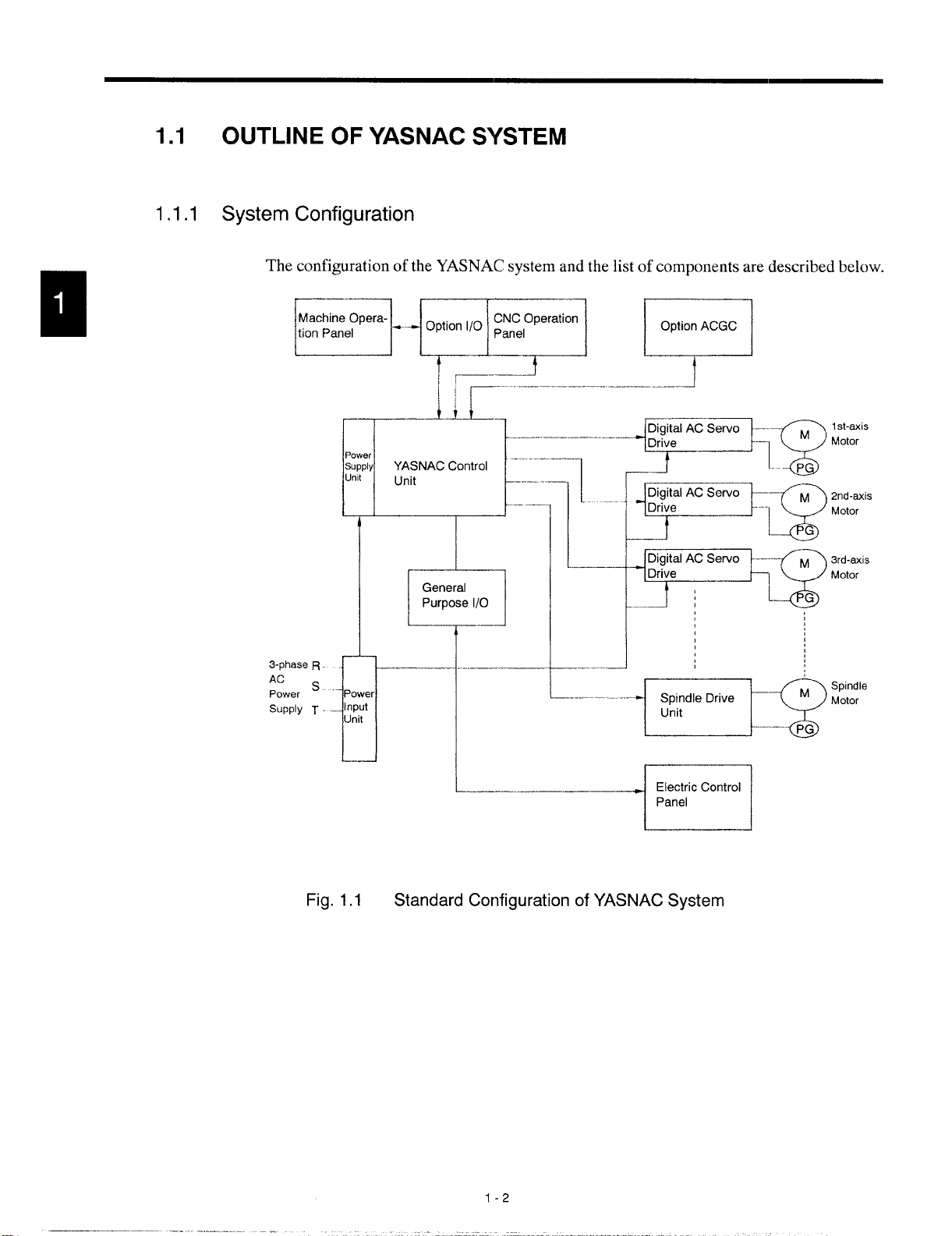
System Configuration . . . . . . . . . . . . . . . . . . . . . . . . . . . . . . . . . . . . . . . . . . 1-2
Environmental Requirements . . . . . . . . . . . . . . . . . . . . . . . . . . . . . . . . . . . . 1-4
Machine Operation Panel . . . . . . . . . . . . . . . . . . . . . . . . . . . . . . . . . . . . . . . 1-6
1.2 PROTECTIVE FIJNCTIONS . . . . . . . . . . . . . . . . . . . . . . . .. . ...1-12
1.2.1
1.2.2 Overtravel . . . . . . . . . . . . . . . . . . . . . . . . . . . . . . . . . . . . . . . . . . . . . . . 1-12
1.2.3 Stored Stroke Limit . . . . . . . . . . . . . . . . . . . . . . . . . . . . . . . . . . . . . . . 1-13
1.2.4 Interlock inputs . . . . . . . . . . . . . . . . . . . . . . . . . . . . . . . . . . . . . . . . . . . 1-15
EmergencyStop . . . . . . . . . . . . . . . . . . . . . . . . . . . . . . . . . . . . . . . . . 1-12
2. BASIC OPERATION OF YASNAC
2.1 GENERAL FLOW OF OPERATION . . . . . . . . . . . . . . . . . . . . ...2-3
2.2 INSPECTION BEFORE TURNING THE POWER ON . . . . . . . ...2-4
2.2.1
2.2.2
2.2.3
2.3 TURNING THE POWER ON AND
2.3.1
2.3.2 Checking the Motors for Abnormalities . . . . . . . . . . . . . . . . . . . . . . . . . 2-10
2.3.3 ProcedureforTurningthe PowerOFF . . . . . . . . . . . . . . . . . . . . . . . . . 2-11
2.3.4 inspection ofthe Battery . . . . . . . . . . . . . . . . . . . . . . . . . . . . . . . . . . . ..2-12
inspection ofthe NC Unit . . . . . . . . . . . . . . . . . . . . . . . . . . . . . . . . . . . . ..2-6
inspection oftheTape Reader.. . . . . . . . . . . . . . . . . . . . . . . . . . . . . . . . . . 2-7’
Preparation before Turningthe Power ON . . . . . . . . . . . . . . . . . . . . . . . . . 2-8
INSPECTION AFTER POWE:R ON...... . . . . . . . . . . . . . . . . ...2-9
ProcedureforTurningthe PowerON . . . . . . . . . . . . . . . . . . . . . . . . . . . . 2-9
2.4 MANUAL OPERATION (I) . . . . . . . . . . . . . . . . . . . . . . . . . . . . ...2-15
2.4.1
2.4.2 Jog Feed (JOG) . . . . . . . . . . . . . . . . . . . . . . . . . . . . . . . . . . . . . . . . . . ...2-16
2.4.3 Step Feed (STEP) . . . . . . . . . . . . . . . . . . . . . . . . . . . . . . . . . . . . . . . . ...2-16
2.4.4 Handle Feed (HANDLE)* . . . . . . . . . . . . . . . . . . . . . . . . . . . . . . . . . ...2-17
Manual Rapid Traverse (RAPID) . . . . . . . . . . . . . . . . . . . . . . . . . . . . ...2-15
1
——.,.— ,—. =. —. —..- ,,.. ! .-~
. ..-.. —-..
—.-. — . . .
Page 3

2.5 MANUAL OPERATION (2) . . . . . . . . . . . . . . . . . . . . . . . . . . . . ...2-18
2.5.1 Simultaneous 3-axis Handle Feed . . . . . . . . . . . . . . . . . . . . . . . . . . . . . .2-18
2.5.2 Manual Reference Point Return . . . . . . . . . . . . . . . . . . . . . . . . . . . . . . ...2-19
2.5.3 Manual Reference Point Return tothe Second Reference Point* . . . . 2-22
2.5.4 I-line MDI . . . . . . . . . . . . . . . . . . . . . . . , . . . . . . . . . . . . . . . . . . . . . . . . ...2-23
2.6 AUTOMATIC OPERATION (1) . . . . . . . . . . . . . . . . . . . . . . . . . ...2-24
2.6.1
2.6.2 Memory Operation . . . . . . . . . . . . . . . . . . . . . . . . . . . . . . . . . . . . . , . . . ...2-26
2.6.3 MDI Operation . . . . . . . . . . . . . . . . . . . . . . . . . . . . . . . . . . . . . . . . . . . . ...2-27
2.6.4 Feed Hold . . . . . . . . . . . . . . . . . . . . . . . . . . . . . . . . . . . . . . . . . . . . . . . . . . .2-28
2.6.5
Preparation of Automatic Operation . . . . . . . . . . . . . . . . . . . . . . . . . . . . . 2-24
Override . . . . . . . . . . . . . . . . . . . . . . . . . . . . . . . . . . . . . . . . . . . . . . . . . . . ..2-29
2.7 AUTOMATIC OPERATION (2) . . . . . . . . . . . . . . . . . . . . . . . . . ...2-31
2.7.1
2.7.2 Optional Block Skip........,., . . . . . . . . . . . . . . . . . . . . . . . . . . . . . . ..2-31
2,7.3 Dry Run . . . . . . . . . . . . . . . . . . . . . . . . . . . . . . . . . . . . . . . . . . . . . . . . . . . ..2-32
2.7.4 Machine Lock......,,....,.. . . . . . . . . . . . . . . . . . . . . . . . . . . . . . . ...2-33
2.7.5 Auxiliary Function Lock . . . . . . . . . . . . . . . . . . . . . . . . . . . . . . . . . . . . . ...2-33
2.7.6 Feed Hold in Thread Cutting*. . . . . . . . . . . . . . . . . . . . . . . . . . . . ., . ...2-34
Optional Stop . . . . . . . . . . . . . . . . . . . . . . . . . . . . . . . . . . . . . . . . . . . . . . ..2-31
2.8 OPERATION INTERVENTION
DURING AUTOMATIC OPERATION . . . . . . . . . . . . . . . . . . . ...2-35
2.8.1 Manual Operation intervention during Automatic Operation . . . . . . . . . 2-35
2.8.2 MDIOperation intervention during Automatic Operation . . . . . . . . . . . . 2-36
2.8.3 Automatic Handle Mode Offset* . . . . . . . . . . . . . . . . . . . . . . . . . . . . . . . . 2-37
2.8.4 Manual Absolute . . . . . . . . . . . . . . . . . . . . . . . . . . . . . . . . . . . . . . . . . . . ..2-38
2.9 AUTOMATIC OPERATIONS AT ENHANCED LEVEL . . . . . ...2-40
2.9.1
2.9.2 Return tothe Operation interrupted Point* . . . . . . . . . . . . . . . . . . . . . . . 2-40
2.9.3 Saving the Present Position Data . . . . . . . . . . . . . . . . . . . . . . . . . . . . . . . . 2-42
2.9.4 Program Restart* . . . . . . . . . . . . . . . . . . . . . . . . . . . . ., ., .,, .,, , . . ...2-43
Return tothe Setup Point . . . . . . . . . . . . . . . . . . . . . . . . . . . . . . . . . . . . ..2-40
3. BASICS OF DISPLAY AND WRITING OPERATION
3.1 BASICS OF TERMS REIATED TO OPERATION ,, . .,..,.....3-2
3.1.1
3.1.2 Jobs and Functions . . . . . . . . . . . . . . . . . . . . . . . . . . . . . . . . . . . . . . . . . . . . 3-3
3.1.3 YASNACJ300L Function Structure . . . . . . . . . . . . . . . . . . . . . . . . . . . . 3-4
Process Screens . . . . . . . . . . . . . . . . . . . . . . . . . . . . . . . . . . . . . . . . . . . . . 3-3
ii
Page 4
3.2 NC OPERATION PANEL . . .. . . . . . . . . . . . . . . . . . . . . . . . . . ...3-8
3.2.1
3.2.2 Normal Display onCRTScreen. . . . . . . . . . . . . . . . . . . . . . . . . . . ...3-15
3.2.3
3.2.4
3.2.5
Keys and Display Screen on NC Operation Panel . . . . . . . . . . . . . . . . 3-8
Pop-up Menu . . . . . . . . . . . . . . . . . . . . . . . . . . . . . . . . . . . . . . . . . . . . . ..3-2o
Key Buffer Edit Function . . . . . . . . . . . . . . . . . . . . . . . . . . . . . . . . . . . ..3-21
Buzzer Function . . . . . . . . . . . . . . . . . . . . . . . . . . . . . . . . . . . . . . . . . . ..3-22
4. EDIT PROCESS OPERATION
4.1 PART PROGRAM EDIT JOB . . . . . . . . . ...0................4-3
4.1.1
4.1.2
4.1.3 Saving aPart Program after [:diting . . . . . . . . . . . . . . . . . . . . . . . . . . . . . 4-22
4.1.4
Calling aPart F’rogram . . . . . . . . . . . . . . . . . . . . . . . . . . . . . . . . . . . . . . . . . 4-4
Editing aPart F’rogram . . . . . . . . . . . . . . . . . . . . . . . . . . . . . . . . . . . . . . . . . 4-7
Deleting aPart Program . . . . . . . . . . . . . . . . . . . . . . . . . . . . . . . . . . . . ...4-23
4.2 PART PROGRAM DIRECTORYJOB . . . . . . . . . . . . . . . . . . ...4-26
4.2.1
4.2.2 Calling aPartl%ogram . . . . . . . . . . . . . . . . . . . . . . . . . . . . . . . . . . . . ...4-33
4.2.3
4.2.4
4.2.5 Copying aPart Program . . . . . . . . . . . . . . . . . . . . . . . . . . . . . . . . . . . . . ..4-39
Display ofthe[lirectory ofPart Programs . . . . . . . . . . . . . . . . . . . . . . . . . 4-26
Deleting aPart Program . . . . . . . . . . . . . . . . . . . . . . . . . . . . . . . . . . . . . ..4-35
Renaming aPart Program . . . . . . . . . . . . . . . . . . . . . . . . . . . . . . . . . . ...4-37
4.3 PART PROGRAM lNPUT/OUTPUTAND VERIFY JOB . . . . ...4-40
4.3.1 inputting aPart Program . . . . . . . . . . . . . . . . . . . . . . . . . . . . . . . . . . . . . ..4-40
4.3.2
4.3.3
4.3.4 Setting the Communication Conditions . . . . . . . . . . . . . . . . . . . . . . . . . . 4-55
4.3.5 Other Function . . . . . . . . . . . . . . . . . . . . . . . . . . . . . . . . . . . . . . . . . . . . . ..4-60
Outputting a Part Program . . . . . . . . . . . . . . . . . . . . . . . . . . . . . . . . . . . ..4-44
Verifying the Part Programs . . . . . . . . . . . . . . . . . . . . . . . . . . . . . . . . . ...4-51
5. SETUP PROCESS OPERATION
5.1 SETUP JOB . . . . . . . . . . . . . . . . . . . . . . . . . . . . . . . . . . . . . . . . . ...5-2
5.1.1
5.1.2 Clearing the Offset Data . . . . . . . . . . . . . . . . . . . . . . . . . . . . . . . . . . . . . . ..5-4
Writing the Tool Offset Data..... . . . . . . . . . . . . . . . . . . . . . . . . . . . . . . . . 5-2
5.2 WORKPIECE COORDINATE SYSTEM SHIFT JOB . . . . . . . . ...5-5
5.2.1
5.2.2 Clearing the Workpiece Coordinate System ShiftAmount . . . . . . . . . . . . 5-6
Writing theWorkpiece Coorclinate System ShiftAmount . . . . . . . . . . . . . 5-5
Page 5
5.3 TOOL LIFE CONTROL JOB . . . . . . . . . . . .,. ,.. s. . . . . . . . . . ...5-7
5.3.1 Writing the Tool Life Control Data... . . . . . . . . . . . . . . . . . . . . . . . . . . ...5-7
5.3.2 Displaying the Tool Lite Control Data. . . . . . . . . . . . . . . . . . . . . . . . . . ...5-7
5.3.3 Setting the Tool Life Control Data,,. . . . . . . . . . . . . . . . . . . . . . . . . . . . . . 5-8
5.3.4 Erasing the Tool Life Control Data... . . . . . . . . . . . . . . . . . . . . . . . . . ...5-10
6. RUN PROCESS
6.1 PROGRAM JOB . . . . . . . . . . . . . . . . . . . . . . . . . . . . . . . . . . . . . . ..6-3
6.1.1
6.1.2 Program Number Search . . . . . . . . . . . . . . . . . . . . . . . . . . . . . . . . . . . . . . . 6-4
6.1.3 Address Search . . . . . . . . . . . . . . . . . . . . . . . . . . . . . . . . . . . . . . . . . . . . . . . 6-6
6.1.4 Editing the Part Program Stored in Memory . . . . . . . . . . . . . . . . . . . . . . . . 6-7
6.1.5
6.1.6 Display of Subprogram Nesting information . . . . . . . . . . . . . . . . . . . . . . 6-10
6.2 MDIOPERATION JOB . . . . . . . . . . . . . . . . ., .,, , . ., . . . . . . ...6-11
Program Information [)isplayed on Screen . . . . . . . . . . . . . . . . . . . . . . . . 6-3
Execution ofa Part Program . . . . . . . . . . . . . . . . . . . . . . . . . . . . . . . . . . . . . 6-9
6.2,1
6.2.2
6.2.3
6.2.4
6.2.5
Entry ofan MDI Program ...,..... . . . . . . . . . . . . . . . . . . . . . . . . . . . . . . 6-11
Editing an MDI Program . . . . . . . . . . . . . . . . . . . . . . . . . . . . . . . . . . . . ...6 -11
Execution ofan MDI Program . . . . . . . . . . . . . . . . . . . . . . . . . . . . . . . ...6- 12
Deleting an MDI Program . . . . . . . . . . . . . . . . . . . . . . . . . . . . . . . . . . . . . . 6-13
Storing an MDI Program..,,. . . . . . . . . . . . . . . . . . . . . . . . . . . . . . . . . . . 6-13
6.3 COMMAND VALUE DISPIAY JOB....,, . . . . . . . . . . . . . . . ...6-14
6.3.1 Collective Display of Command Values . . . . . . . . . . . . . . . . . . . . . . . . . . 6-14
6.4 SEITING JOB...............,,.,,.. . . . . . . . . . . . . . . . . ...6-15
6.4.1 internal Switch Function*..,,, . . . . . . . . . . . . . . . . . . . . . . . . . . . . . . . . . 6-15
6.4.2 Software Switch Function* . . . . . . . . . . . . . . . . . . . . . . . . . . . . . . .,, ..,6-16
6.4.3 Macro Variable Function, ...,, . . . . . . . . . . . . . . . . . . . . . . . . . . . . . . . . . 6-17
6.4.4 Setting Function.,.......,.. . . . . . . . . . . . . . . . . . . . . . . . . . . . ., .,...6-19
7. COMMON PROCESS OPERATION
7,1 PRESENTPOSITION [)ATACONTROLJOB . . . . . . . . . . . . . ...7-2
7.1.1 Collective Display ofPresentPosition Data . . . . . . . . . . . . . . . . . . . . . . . . 7-2
7.1.2 Display of Present Position Data
7.1.3 Display of Present Position Data
7.1.4 Display of Remaining Distance. . . . . . . . . . . . . . . . . . . . . . . . . . . . . . . ...7-6
7.1.5 Setting the Coordinate Systems . . . . . . . . . . . . . . . . . . . . . . . . . . . . . . . 7-7
7.1.6 Error Pulse Display Function.. . . . . . . . . . . . . . . . . . . . . . . . . . . . . ., . ...7-9
in the Workpiece Coordinate System . . . . . . . . . . . . . . . . . . . . . . . . . . . . . 7-4
in the External Coordinate Values . . . . . . . . . . . . . . . . . . . . . . . . . . . . . ...7-5
—-...—-...——..-—.—
iv
Page 6
7.2 ALARM DISPLAY JOB . . . . . . . . . . . . . . . . . . . . . . . . . . . . . ...7-10
7.2.1
7.2.2 Servo Alarm Function . . . . . . . . . . . . . . . . . . . . . . . . . . . . . . . . . . . . . . . ..7-11
7.2.3
Alarm Functiorl . . . . . . . . . . . . . . . . . . . . . . . . . . . . . . . . . . . . . . . . . . . . ...7-10
User’s Message Function . . . . . . . . . . . . . . . . . . . . . . . . . . . . . . . . . . . . ..7-12
7.3 TIME CONTROL. JOB . . . . . . . . . . . . . . . . . . . . . . . . . . . . .. . ...7-13
7.3.1 Calendar Function . . . . . . . . . . . . . . . . . . . . . . . . . . . . . . . . . . . . . . . . . ..7-14
7.3.2 Operating Time Function . . . . . . . . . . . . . . . . . . . . . . . . . . . . . . . . . . . ...7-15
8. MAINTENANCE PROCESS
8.1 PARAMETER JOB . . . . . . . . . . . . . . . . . . . . . . . . . . . . . . . .. . . ...8-3
8.1.1
8.1.2 Setting Functio n. . . . . . . . . . . . . . . . . . . . . . . . . . . . . . . . . . . . . . . . . . . . . . 8-6
8.1.3 Sequence ParameterFuncti~n . . . . . . . . . . . . . . . . . . . . . . . . . . . . . . . . . . 8-7
8.1.4 Pitch Error Furlction *....... . . . . . . . . . . . . . . . . . . . . . . . . . . . . . . . . . . . 8-7
8.2 l/O MONITORING JOB . . . . . . . . . . . . . . . . . . . . . . . . . . . . . . . ...8-8
8.2.1
8.2.2 DisplayingtheON/OFFStatusofthe Selectedl/OSignals . . . . . . . . . . . 8-9
8.2.3 TurningON/OFFl/OSignalsForcibly . . . . . . . . . . . . . . . . . . . . . . . . . . . . 8-11
Parameter Function . . . . . . . . . . . . . . . . . . . . . . . . . . . . . . . . . . . . . . . . . . . . 8-3
DisplayingtheON/OFFStatusof thel/OSignals . . . . . . . . . . . . . . . . . . . 8-8
8.3 lNPUT/OUTPUT AND VERIF’YJOB . . . . . . . . . . . . . . . . . . . ...8-12
8.3.1
8.3.2
8.3.3
input/outputandVerifyFunction . . . . . . . . . . . . . . . . . . . . . . . . . . . . . ...8-12
Reset Functiorl . . . . . . . . . . . . . . . . . . . . . . . . . . . . . . . . . . . . . . . . . . . . . ..8-14
l/ODeviceSettingFunction . . . . . . . . . . . . . . . . . . . . . . . . . . . . . . . . . . ..8-14
8.4 INTERNAL INFORMATION *JOB . . . . . . . . . . . . . . . . . . . . . . ...8-15
8.4.1
8.4.2
8.4.3
Version Number Function . . . . . . . . . . . . . . . . . . . . . . . . . . . . . . . . . . . . 8-15
Memory Dump Function . . . . . . . . . . . . . . . . . . . . . . . . . . . . . . . . . . . . . 8-16
Key Memory Function . . . . . . . . . . . . . . . . . . . . . . . . . . . . . . . . . . . ...8-16
9. MAINTENANCE
9.1 MAINTENANCE DATA . . . . . . . . . . . . . . . . . . . . . . . . . . . . . . . ...9-2
9.1.1
9.1.2 Checking the lVClnformation. . . . . . . . . . . . . . . . . . . . . . . . . . . . . . . . . 9-3
9.1.3 Display ofAlarm lnformatiorl . . . . . . . . . . . . . . . . . . . . . . . . . . . . . . . . . . . 9-5
9.1.4
9.1.5 Troubleshooting (l) . . . . . . . . . . . . . . . . . . . . . . . . . . . . . . . . . . . . . . . . . . 9:7
9.1.6 Troubleshooting (2) . . . . . . . . . . . . . . . . . . . . . . . . . . . . . . . . . . . . . . . ...9 -17
9.1.7 Alarms Not indicated byAlarm Numbers . . . . . . . . . . . . . . . . . . . . . . . 9-23
Checking the StatusofTroubles. . . . . . . .. . . . . . . . . . . . . . . . . . . . . . 9-2
Cause ofAlarrn and Corrective Action . . . . . . . . . . . . . . . . . . . . . . . . . . 9-6
v
Page 7
APPENDIX 1 LIST OF NC lNPUT/OUTPUT SIGNALS
APPENDIXI.I INPUT SIGNALS (PLC--+ NC) . . . . . . . . . . . . . . . . .. A1-2
1.1.1 Operation Mode Control . . . . . . . . . . . ., . . . . . . . . . . . . . . . . . . . . . . . . .. A1-2
1.1.2 CNCPart Program Execution Control . . . . . . . . . . . . . . . . . . . . . . . . . . .. A1-4
1.1.3 ServoAxis Control . . . . . . . . . . . . . . . . . . . . . . . . . . . . . . . . . . . . . . . . . . ..A1-5
1.1.4 No. l Spindle Control.....,., . . . . . . . . . . . . . . . . . . . . . . . . . . . . . . . ..A1-7
1.1.5
1.1.6 YENET1200Compatible lnverter Control . . . . . . . . . . . . . . . . . . . . . . . . . Al-9
No. 2SpindleControl . . . . . . . . . . . . . . . . . . . . . . . . . . . . . . . . . . . . . . . ..A1-8
APPENDIX 1.2 OUTPUT SiGNALS (NC-+ PLCj . . . . . . . . . . . . . . Al -10
1.2.1
1.2.2 NC Part Program Execution Control. . . . . . . . . . . . . . . . . . . . . . . . . . .. A1- 12
1.2.3 Servo Axis Control, . ., . .,, . . . . . . . . . . . . . . . . . . . . . . . . . . . . . . . . . .. Al- 14
1.2.4 No, l Spindle Control . . . . . . . . . . . . . . . . . . . . . . . . . . . . . . . . . . . . . . .. Al- 17
1.2.5 No.2Spindle Control . . . . . . . . . . . . . . . . . . . . . . . . . . . . . . . . . . . . . . .. A1 -18
1.2.6 YENET1200Compatible lnverter Control . . . . . . . . . . . . . . . . . . . . . . . . A1 -19
1.2.7 Axis Variable Data, . . . . . . . . . . . . . . . . . . . . . . . . . . . . . . . . . . . . . . . . .. Al- 20
Operation Mode Control ., .,.,..... . . . . . . . . . . . . . . . . . . . . . . . . . .. A1 -10
APPENDIX 2 PARAMETER TABLE
APPENDIX 2.1 CLASSIFICATION OF THE PARAMETERS . . . . . . . A2 -2
APPENDIX 2.2 PARAMETER TABLE . . . . . . . . . . . . . . . . . . . . . . . . .. A2-3
APPENDIX 3 ALARM TABLE
APPENDIX 3.1 CLASSIFICATION OF ALARMS . . . . . . . . . . . . . . . . . A3 -2
APPENDIX 3.2 ALARM TA13LE . . . . . . . . . . . . . . . . . . . . . . . . . . . . . .. A3-3
APPENDIX 4 INDEX
vi
Page 8
FOREWORD
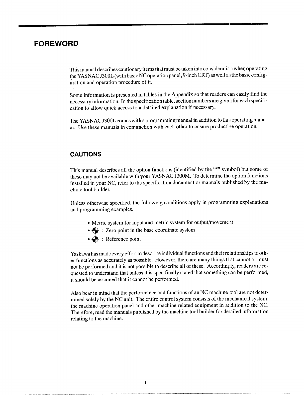
This manual describes cautionary items that must be taken into consideraticm when operating
the YASNAC J300L (with basic NC operation panel, 9-inch CRT) as well as the basic configuration and operation procedure of it.
Some information is presented in tables in the Appendix so that readers can easily find the
necessary information. In the specification table, section numbers are given for each specification to allow quick access to a detailecl explanation if necessary.
The YASNAC J300L comes with a programming manual in addition to thi~;operating manual. Use these manuals in conjunction with each other to ensure productive operation.
CAUTIONS
This manual describes all the option functions (identified by the “*” symbol) but some of
these may not be available with your YASNAC J300M. To determine the option functions
installed in your NC, refer to the specification document or manuals published by the machine tool builder.
Unless otherwise specifiecl, the following conditions apply in programming explanations
and programming examples.
. Metric system for input and metric system for output/moveme.~t
●
: Zero point in the base coordinate system
+
●
: Reference point
@
Yaskawa has made every effort to describe individual functions and their relationships to other functions as accurately as possible. However, there are many things ttat cannot or must
not be performed and it is not possible to describe all of these. Accordingly, readers are requested to understand that unless it is specifically stated that something can be performed,
it should be assumed that it cannot be performed.
Also bear in mind that the :performance and functions of an NC machine tool are not determined solely by the NC unit. The entire control system consists of the mechanicals ystem,
the machine operation panel and other machine related equipment in addition to the NC.
Therefore, read the manuals published by the machine tool builder for derailed information
relating to the machine.
Page 9

General Precautions
● Some drawings in this manual are shown with the protective cover or shields removed,
in order to describe the detail with more clarity. Make sure all covers and shields are
replaced before operating this product, and operate it in accordance with the directions
in the manual.
● The figures and photographs in this manual show a representative product for reference
purposes and may differ from the product actually delivered to you.
● This manual maybe modified when necessary because of improvement of the product,
modification, or changes in specifications.
Such modification is made as a revision by renewing the manual No.
● To order a copy of this manual, if your copy has been damaged or lost, contact your
Yaskawa representative listed on the last page stating the manual No. on the front
page.
● If any of the nameplates affixed to the product become damaged or illegible, please
send these nameplates to your Yaskawa representative.
● Yaskawa is not responsible for any modification of the product made by the user since
that will void our guarantee.
.——— —
ii
Page 10
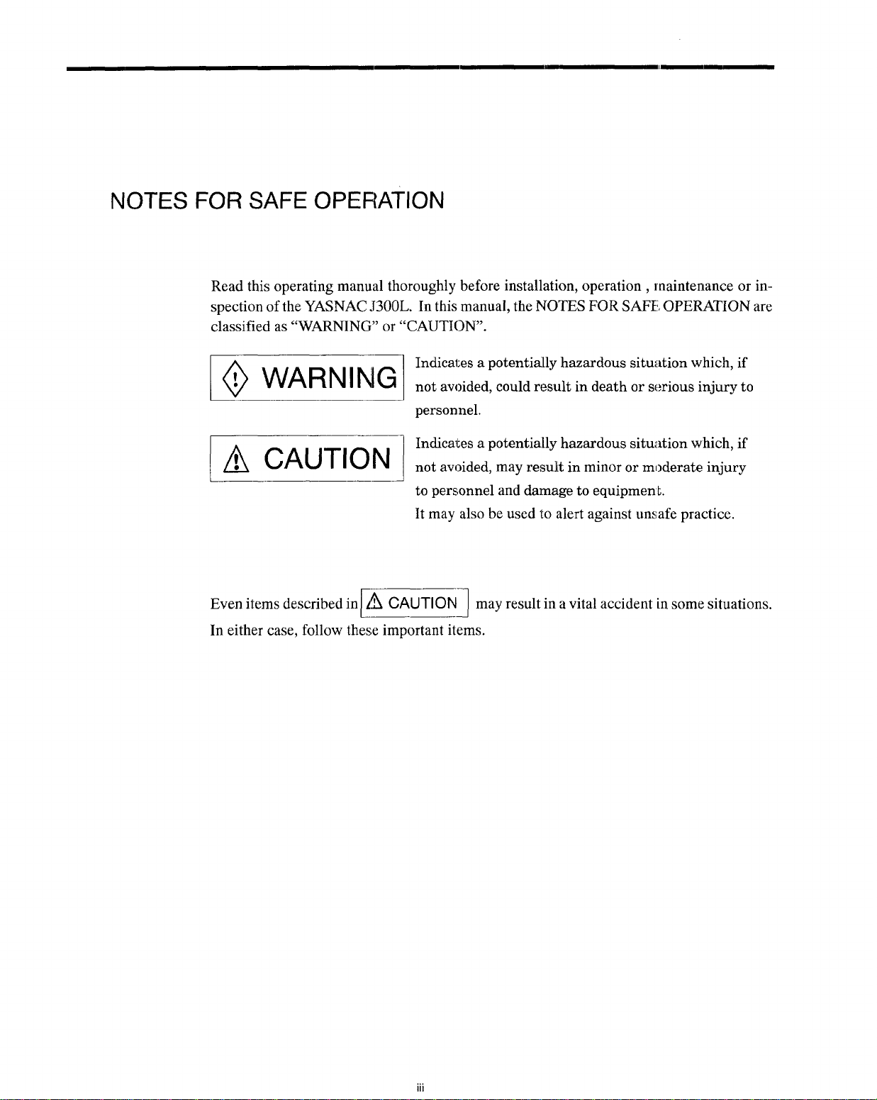
NOTES FOR SAFE OPEF{ATION
Read this operating manual thoroughly before installation, operation , maintenance or inspection of the YASNAC J300L. In this manual, the NOTES FOR SAFE OPERATION are
classified as “WARNING” or “CAUTION’.
Indicates a potentially hazardous situation which, if
~ WARNING
~ CAUTION
Even items describedinl ~ CAUTION I may result in a vital accident in some situations.
not avoided, could result in death or serious injury to
personnel.
Indicates a potentially hazardous situi~tion which, if
not avoided, may resuR in minor or moderate injury
to personnel and damage to equipmenk
It may also be used to alert against unsafe practice.
In either case, follow these important items.
Page 11
KEY TO WARNING LABELS
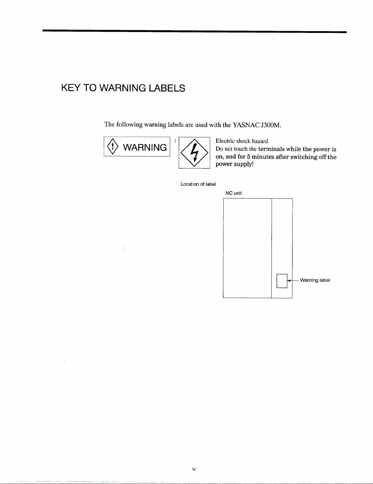
The following warning labels are used with the YASNAC J300M.
mq~q ::;::ard
Do not touch the terminals while the power is
on, and for 5 minutes after switching off the
Locationoflabel
NCunit
— Warninglabel
iv
Page 12
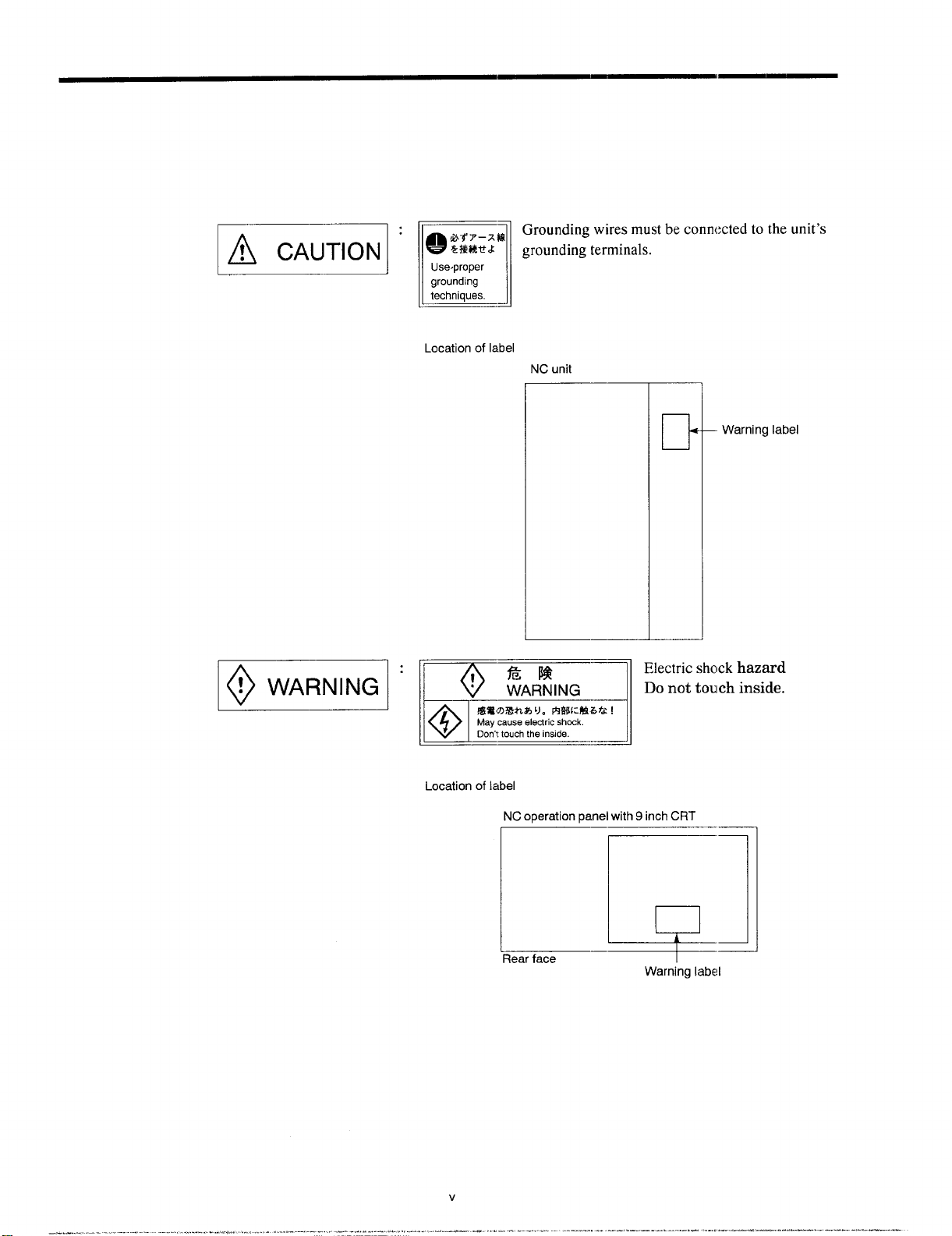
E:
,fi#Y-xkfi
Mi%M&
Q
Use,proper
grounding
techniques.
n
Locationoflabel
Grounding wires must be connected to the unit’s
grounding terminals.
NCunit
—.
Warninglabel
! WARNING
O
IW#UX%n%’JoF%Ji:M3ti !
Maycauseelectric shock.
Il@l
Locationoflabel
Don?touti theinside.
-J
—
NCoperationpanelwith9inchCRT
L]
—–’—
Rearface
Warninglabel
Page 13
1
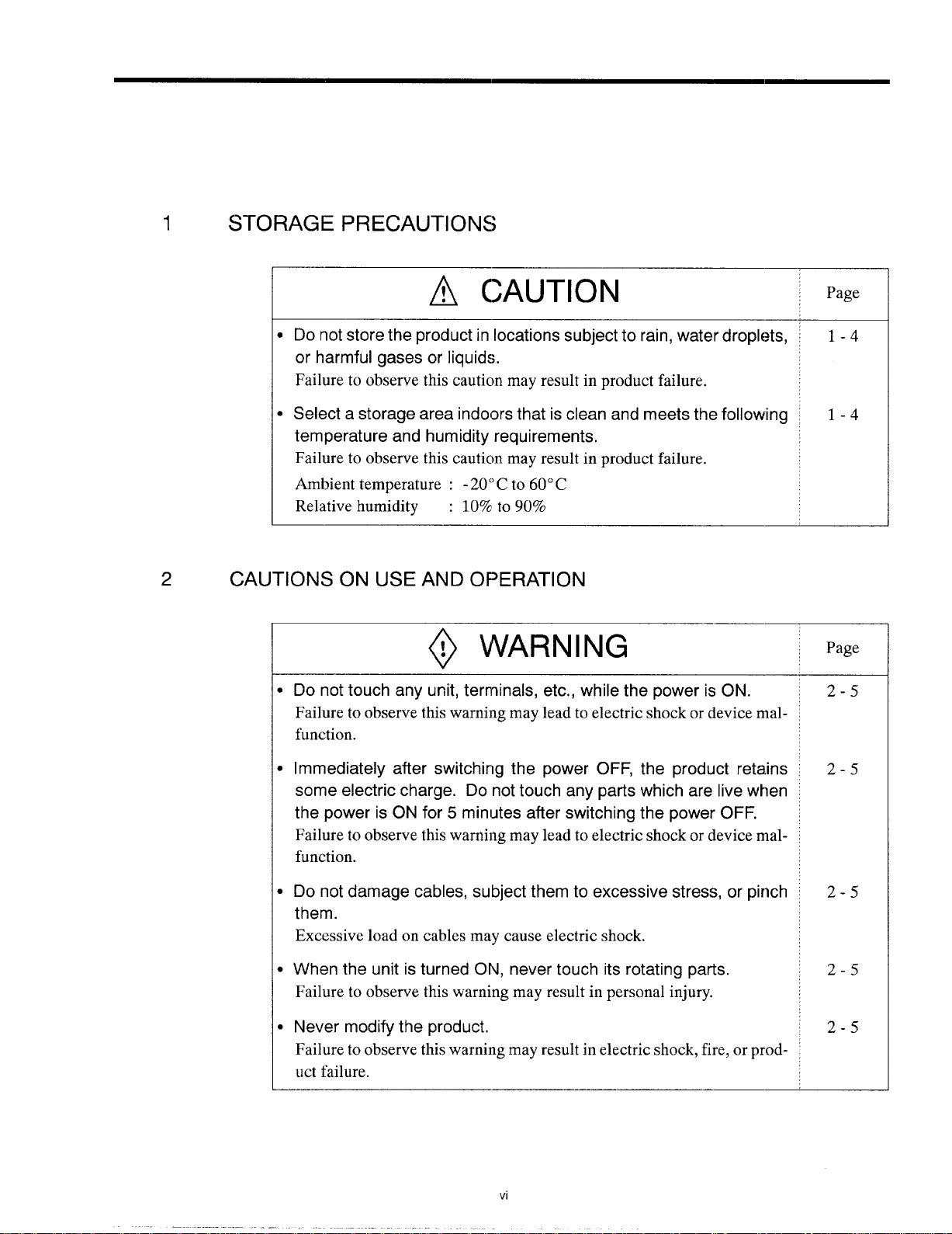
STORAGE PRECAUTIONS
~ CAUTION
Do not store the product in locations subject to rain, water droplets,
or harmful
gases or liquids.
Page
1-4
Failure to observe this cauticm may result in product failure.
Select a storage area
temperature
and humidity requirements.
indoors that is clean and meets the following
1-4
Failure to observe this caution may result in product failure.
Ambient temperature : - 20’)C to 60° C
Relative humidity : 10%
2
CAUTIONS ON USE
AND OF’ERATION
~ WARNING
B
Do not touch any unit, terminals, etc., while the power is ON.
to 90%
Page
2-5
Failure to observe this warning may lead to electric shock or device malfunction.
●
Immediately after switching the power
some electric
charge. Do not touch any parts which are live when
the power is ON for 5 minutes after switching the power
OFF, the product retains
OFF.
Failure to observe this warning may lead to electric shock or device malfunction.
●
Do not damage cables, subject them to excessive stress, or pinch
them.
Excessive load on cables may cause electric shock.
●
When the unit is turned ON, never touch its rotating parts.
Failure to observe this warning may result in personal injury.
●
Never modify the product,
Failure to observe this warning may result in electric shock, fire, or product failure.
—
2-5
2-5
2-5
2-5
Page 14
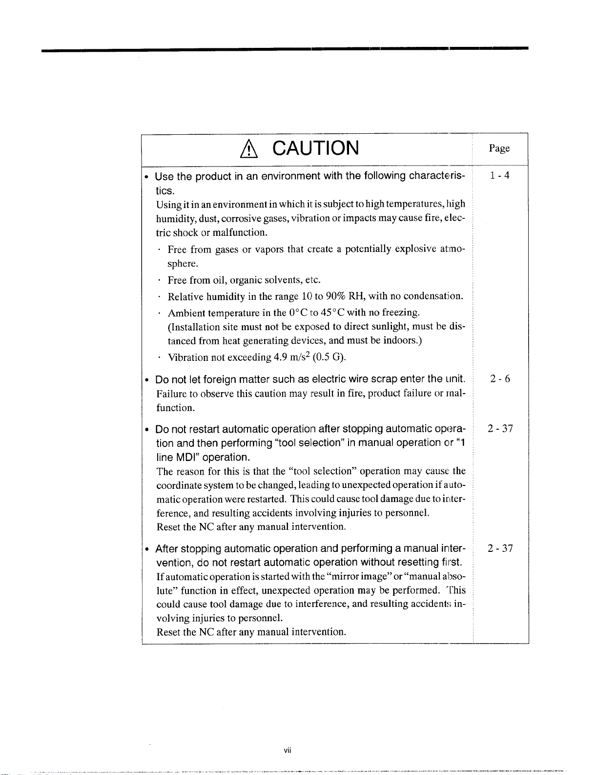
~ CAUTION
Use the product in an environment with the following characteris-
tics.
Using it in an environment in which it is subject to high temperatures, high
humidity, dust, corrosive gases, vibration or impacts may cause fire, electric shock or malfunction.
Free from gases or vapors that create a potentially explosive atmosphere.
.
Free from oil, organic solvents,
Relative humidity in the range 10I to 90% RH, with no condensation.
Ambient temperature in the O“C to 45° C with no freezing.
(Installation site must not be exposed to direct sunlight, must be distanced from heat generating devices, and must be indoors.)
Wbration not exceeding 4.9 m/s2 (0.5 G).
etc.
Page
-——
1-4
I
Do not let foreign matter such as electric wire scrap enter the unit.
Failure to observe this caution may :result in fire, product failure or malfunction.
I
Do not restart automatic operation after stopping automatic operation and then performing “tool selection” in manual operation c)r”1
line MDI” operation.
The reason for this is that the “tool selection” operation may cause the
coordinate system to be changed, leading to unexpected operation if a utomatic operation were restarted. This could cause tool damage due to irlterference, and resulting accidents involving injuries to personnel.
Reset the NC after any manual intervention.
)
After stopping automatic operation and performing a manual irlter-
vention, do not restart automatic operation without resetting first.
If automatic operation is started with the “mirror image” or “manual a’l]solute” function in effect, unexpected operation may be performed. “rhis
could cause tool damage due to interference, and resulting accidents involving injuries to personnel.
Reset the NC after any manual intervention.
—
2-6
2-37
2-37
Page 15
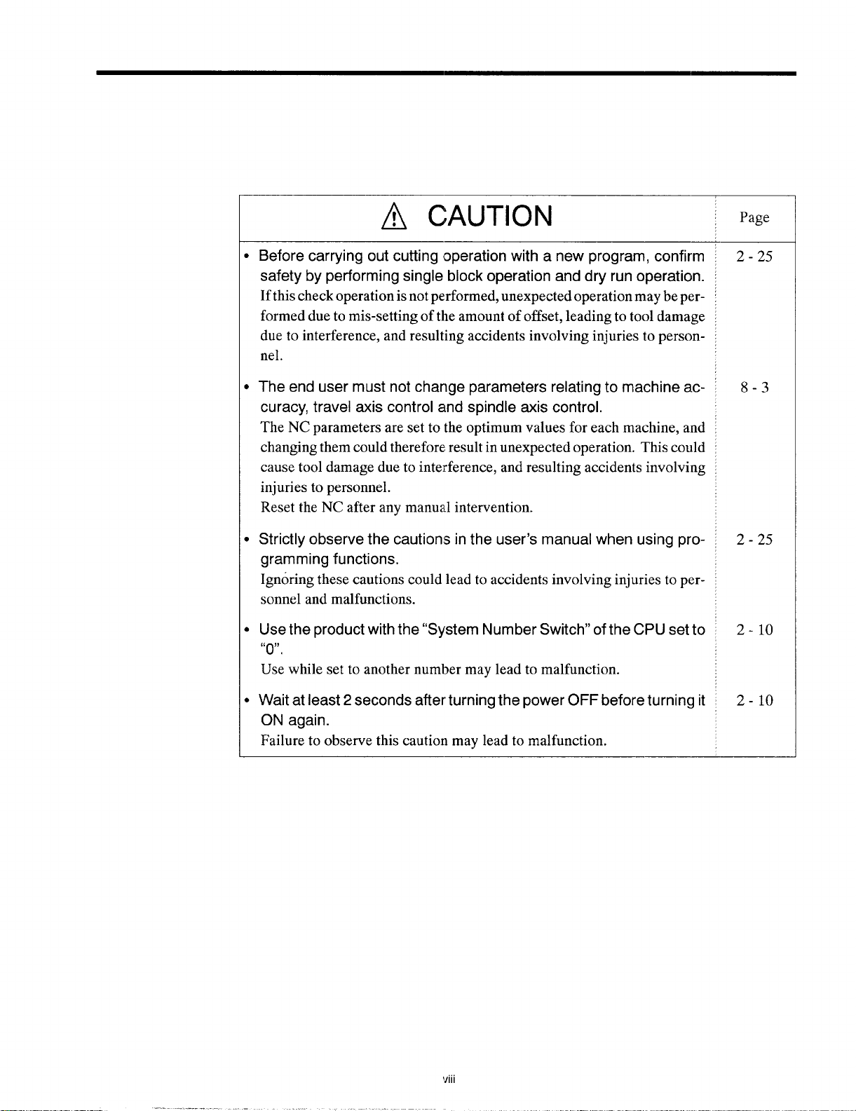
~ CAUTION
Page
Before carrying out cutting operation with a new program, confirm
safety by performing single block operation and dry run operation.
If this check operation is not performed, unexpected operation maybe performed due to mis-setting of the amount of offset, leading to tool damage
due to interference, and resulting accidents involving injuries to perscmnel.
The end user must not change parameters relating to machine ac-
curacy, travel axis control and spindle axis control.
The NC parameters are set to the optimum values for each machine, and
changing them could therefore result in unexpected operation. This could
cause tool damage due to interference, and resulting accidents involving
injuries to personnel.
Reset the NC after any manual intervention.
Strictly observe the cautions in the user’s manual when using pro-
gramming functions.
Ignoring these cautions could lead to accidents involving injuries to personnel and malfunctions.
Use the product with the “System Number Switch” of the CPU set to
6’ ,,
0.
Use while set to another number may lead to malfunction.
2-25
8-3
2-25
2-1o
Wait at least 2 seconds after turning the power OFF before turning it
ON again.
Failure to observe this caution may lead to malfunction.
Vlll
2-1o
Page 16
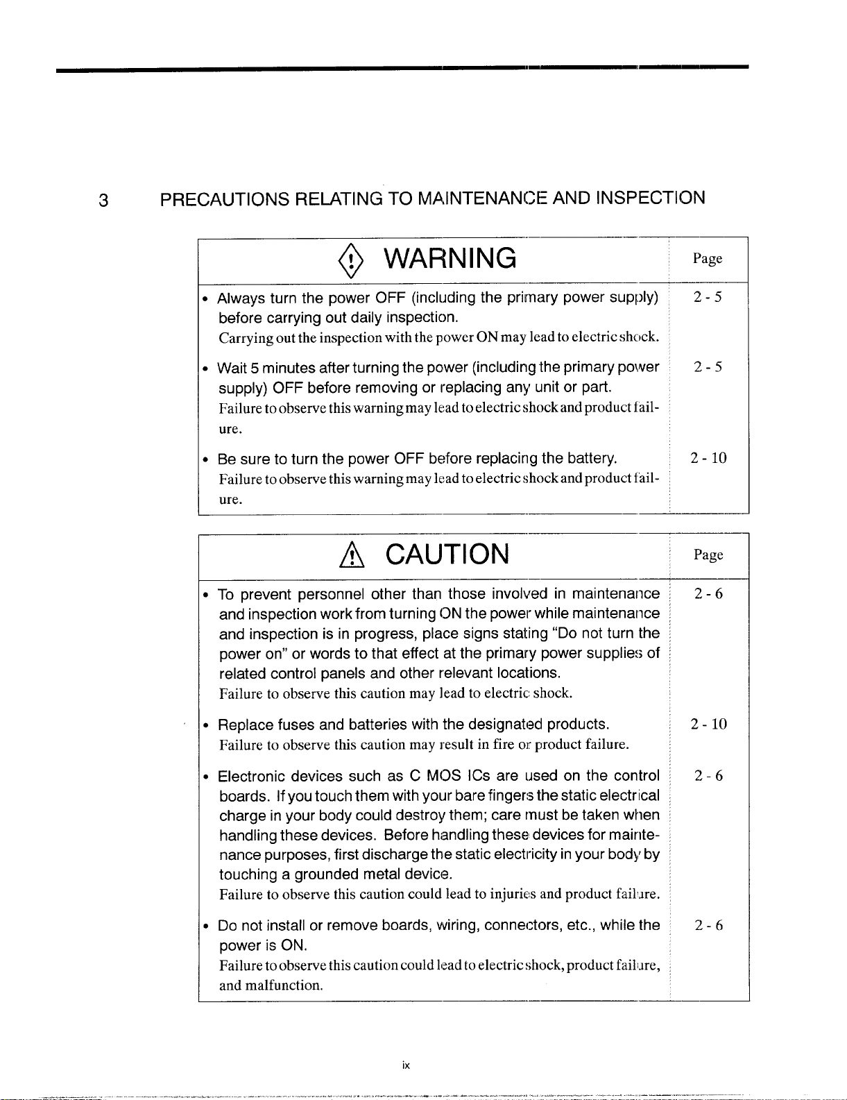
3
PRECAUTIONS RELATING TO MAINTENANCE AND INSPECTION
@ WARNING ‘-
● Always turn the power OFF (including the primary power supply)
before carrying out daily inspection.
Carrying out the inspection with the power ON may lead to electric shock.
● Wait 5 minutes after turning the power (including the primary power
supply) OFF before removing or replacing any unit or part.
Failure to observe this warning may lead to electric shock and product iailure.
● Be sure to turn the power OFF before replacing the battery.
Failure to observe this warning may lead to electric shock and product ~ailure.
~
I To prevent personnel other than those involved in maintenance ~
inspection work from turning ON the power while maintenance
and
and inspection is in progress, place signs stating “Do not turn the
power on” or words to that effect at the primary power supplies of ~
related control panels and other relevant locations.
Failure to observe this caution may lead to electric shock.
CAUTION
—
Page
2-5
2-5
2-1o
Page
2-6
I Replace fuses and batteries with the designated products.
Failure to observe this caution may result in fire
I Electronic devices such as C MOS ICS are used on the control
boards. If you touch them with your bare fingers the static electrical
charge in your body could destroy them; care must be taken when
handling these devices. Before handling these devices for mair]tenance purposes, first discharge the static electricity in your body by
touching a grounded metal device.
Failure to observe this caution could lead to injurim and product fail.me.
I Do not install or remove boards, wiring, connectors, etc., while the
power is ON.
Failure to observe this caution could leadto electric shock, product fail~re,
and malfunction.
or product failure.
.— .——
2-1o
2-6
2-6
Page 17
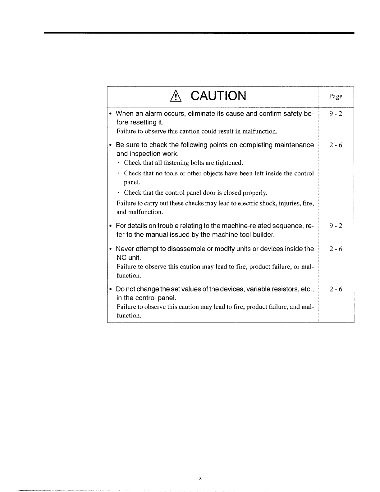
~ CAUTION
Page
When an alarm occurs, eliminate its cause and confirm safety be-
fore resetting it.
Failure to observe this cautio:n could result in malfunction.
Be sure to check the following points on completing maintenance
and inspection work.
. Check that all fastening bolts are tightened.
“ Check that no tools or other objects have been left inside the control
panel.
. Check that the control panel door is closed properly.
Failure to carry out these checks may lead to electric shock, injuries, fire,
and malfunction.
For details on trouble relating to the machine-related sequence,
fer to the manual issued by the machine tool builder.
Never attempt to disassemble or modify units or devices inside the
NC unit.
Failure to observe this caution may lead to fire, product failure, or malfunction.
Do not change the set values of the devices, variable resistors, etc.,
in the control panel.
Failure to observe this caution may lead to fire, product failure, and malfunction.
re-
9-2
2-6
9-2
2-6
2-6
Page 18
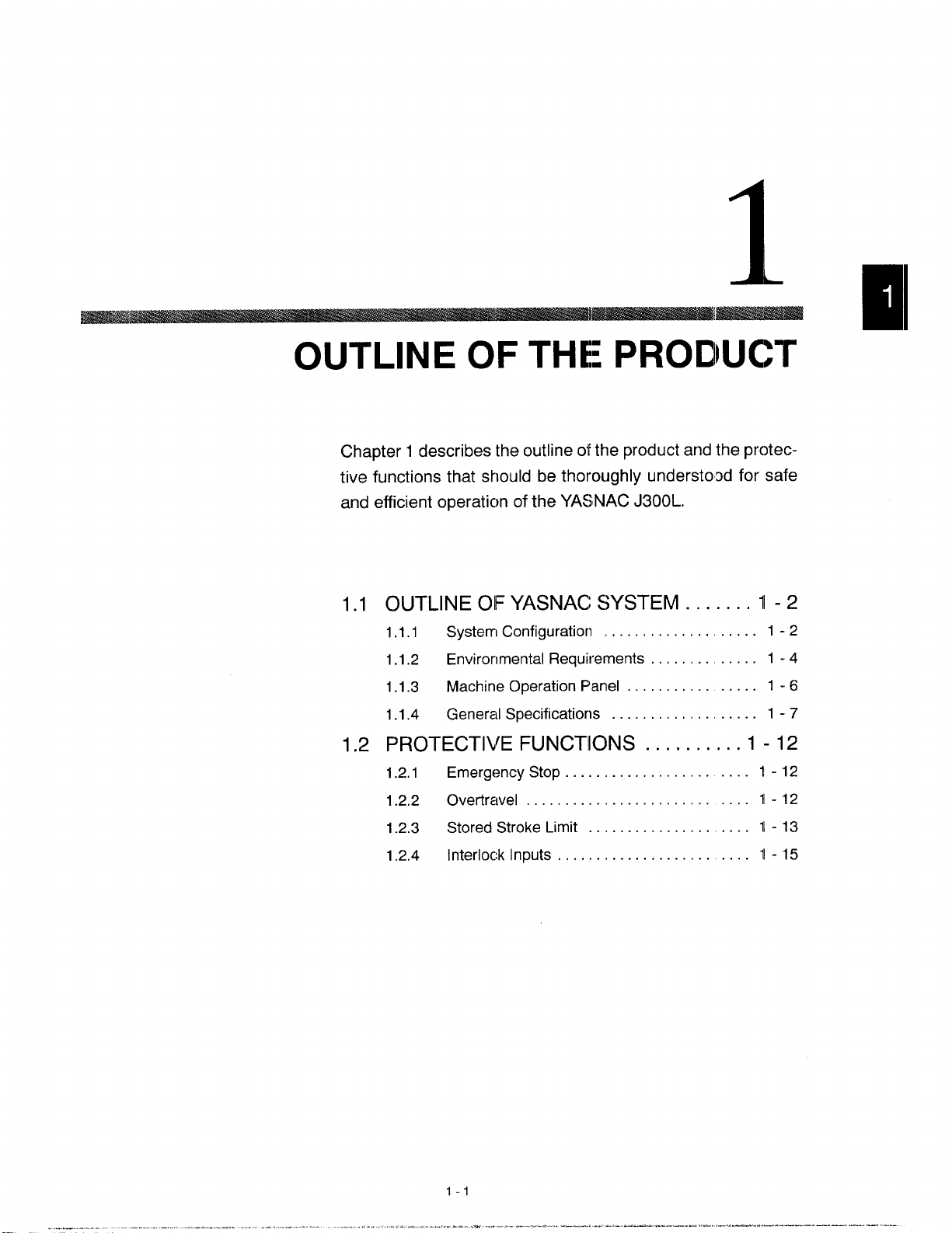
OUTLINE OF THE: PRODUCT
Chapter 1 describes the outline of the product and the protective functions that should be thoroughly understood for safe
and efficient operaticm of the YASINAC J300L.
1.1
OUTLINE OF YASNAC SYSTEM . . . . ...1-2
1.1.1 Systerrl Configuratiorl . . . . . . . . . . . . . . . . . 1-2
1.1.2 Environmental Requirements . . . . . . . . . . . . 1 -4
1.1.3 Machine Operation Panel . . . . . . . . . . . . . . . . 1-6
1.1.4 General Specificatiorls . . . . . . . . . . . . . . . . . 1-7
1.2
PROTECTIVE FUNCTIONS . . . . . . . ...1-12
1.2.1
1.2.2 Overtrave l . . . . . . .. o. . . . . . . . . . . . . . . . . . 1-12
1.2.3 Stored Stroke Limit . . . . . . . . . . . . . . . . . . . 1-13
1.2.4
Emergenc ySto p. . . . . . . . . . . . . . . . . . . . . . 1-12
Interlock Inputs . . . . . . . . . . . . . . . . . . . . . . . . 11-15
Page 19
1.1
1.1.1 System Configuration
OUTLINE OF YASNAC SYSTEM
The configuration of the YASNAIC system and the list of components are described below.
m“”EjEI!!Iyl
OptionACGC
Q
3-phase R
AC
Power
SUPPty T
Power
supply
Unit
YASNACControl
Unit
FE:
General
Purpose1/0
~1
-L--–A----J ~ !
r
s
Power
Input
—
Unit
u
Fig. 1.1
t
r
pmfim=--g,,:,s
1
I
‘1
-Fl?’”is
L
ElectricControl
Panel
1
Configuration of YASNAC System
I..+’@
,
Page 20
1.1 OUTLINEO= YASNACSYSTEM
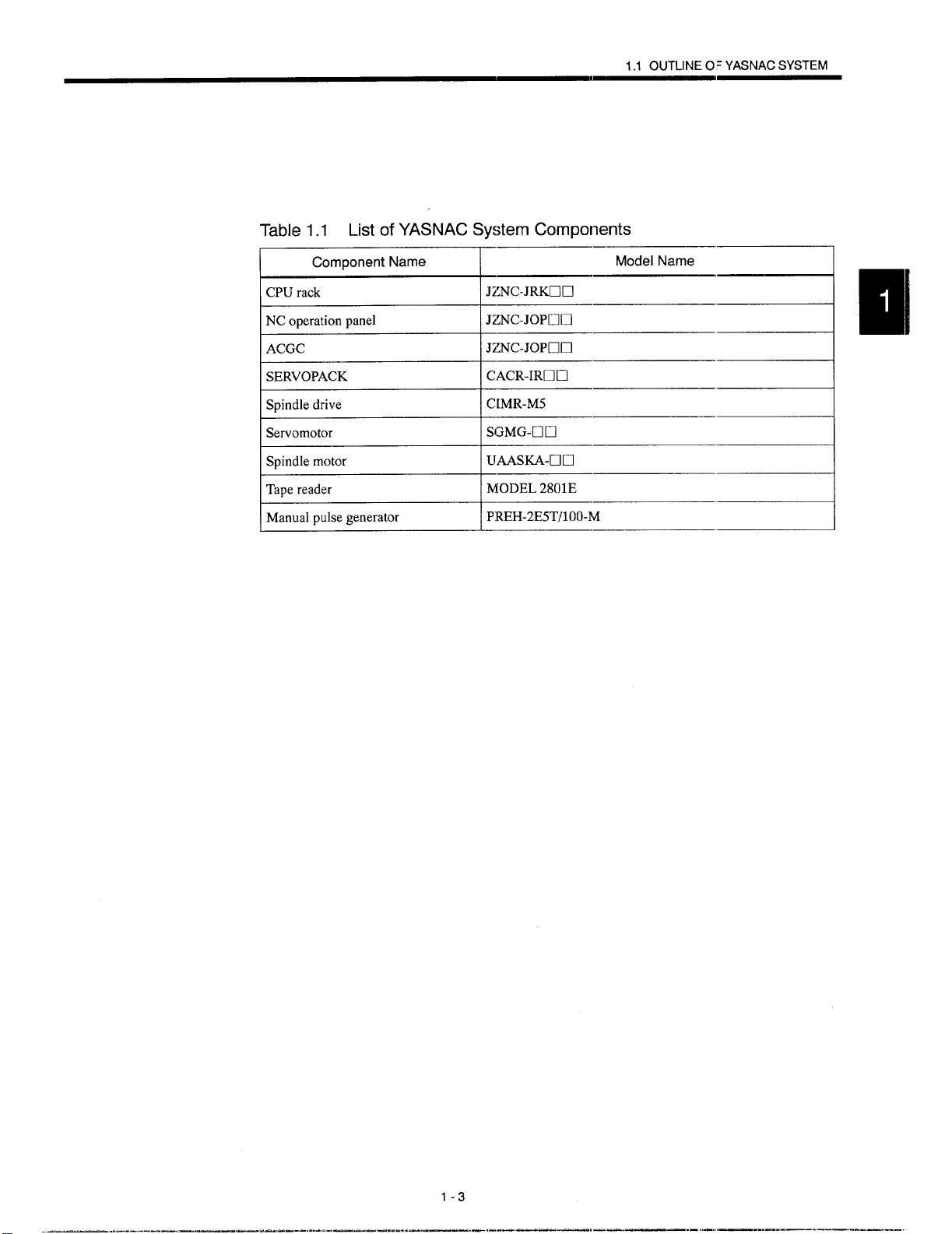
Table 1.1 List of YASNAC System Components
~:..-n...n ““de’”’”’
NCoperationpanel
JZNC-JOPUIJ
ACGC
SERVOPACK
Spindledrive
Servomotor
Manualpulsegenerator
JZNC-JOPCiU
\CACR-IRUU
CIMR-M5
SGMG-CIEl
PREH-2E5T/100-M
1-3
Page 21
1.1.2 Environmental Requirements
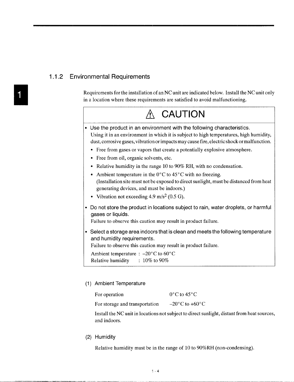
Requirements for the installation of an NC unit are indicated below. Install the NC unit only
in a location where these requirements are satisfied to avoid malfunctioning.
B
Use the product in an environment with the following characteristics.
Using it in an environment in which it is subject to high temperatures, high humidity,
dust, corrosive gases, vibration or impacts may cause fire, electric shock or malfunction.
Free from gases or vapors that create a potentially explosive atmosphere.
Free from oil, organic solvents, etc.
Relative humidity in the range 10 to 90% RH, with no condensation.
Ambient temperature in the 0° C to 45° C with no freezing.
(Installation site must not be exposed to direct sunlight, must be distanced from heat
generating devices, and must be indoors.)
Vibration not exceeding 4.9 m/s2 (0.5 G).
●
Do not store the product in locations subject to rain, water droplets, or harmful
gases or liquids.
Failure to observe this caution may result in product failure.
~, CAUTION
●
Select a storage area indocrs that is clean and meets the following temperature
and humidity requirements.
Failure to observe this caution may result in product failure.
Ambient temperature : –20° C to 60° C
Relative humidity
(1)
Ambient Temperature
For operation
For storage and transportation
: 10% to 90%
0°cto450c
–20°C to +60° C
Install the NC unit in locations not subject to direct sunlight, distant from heat sources,
and indoors.
(2)
Humidity
Relative humidity must be in the range of 10 to 90%RH (non-condensing).
“l-4
Page 22
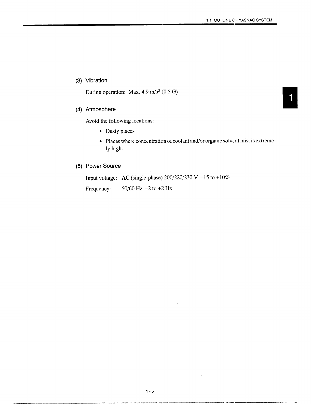
(3) Vibration
During operation: Max.4.9m/s2(0.5G)
(4) Atmosphere
Avoid the following locations:
. Dusty places
1.1 OUTLINEC)FYASNACSYSTEM
Q Places where concentraticm of coolant and/or
ly high.
(5) Power Source
Input voltage: AC (single-phase) 200/220/230 V –15 to
Frequency:
50/60 Hz –2 to +2 Hz
Organic sok nt mist is extreme-
+10%
1-5
.— -
.. —.—.. #-,,—.—.— ..———..
Page 23
1.1,3
Machine Operation Panel
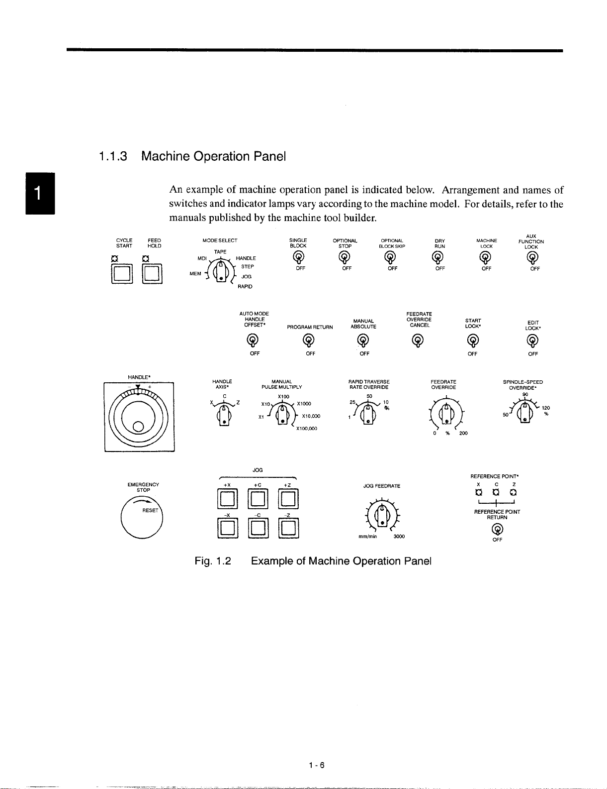
An
example of machine operation panel is indicated below. Arrangement and names of
switches and indicator lamps vary according to the machine model. For details, refer to the
manuals published by the machine tool builder.
E
la
CYCLE
START
FEED MODE SELECT
HOLD
~ ‘E:~!? z ~F $?F Q @
HANDLE,
+
0
o
O
EMERGENCY
STOP
RESET
o
SINGIE
TAPE
RAPID
AUTOMODE
HANDLE
OFFSET,
(?(?
OFF OFF
mNDLE MANUAL
AXIS*
’62 ~If$~””
JOG
Imm
mm “.
BLOCK
PRCGFIAMFIETURN
PULSEMULTIPLY
X1OO,IXX1
0P70NAL
STOP BLOCKSIUP RUN
MANUAL
ABSOLUTE
Q
OFF
RAPIDTRAVERSE
RATEOVERRIDE
25 10
7@
1
nmlmn
0PTION4L
50
w
e
JOG FEEDRATE
@
FEEDF!ATE
OVERRIOE
CANCEL
DRY
OFF
FEEDRATE
OVERRIDE
MACHINE
LCCK
OFF
START
LCCK*
REFERENCEFUINT.
;;;
1
1
REFERENCEPCINT
REIURN
@
OFF
Au’
FUNCTION
LOCK
Q
OFF
EOIT
LOCK.
6)
OFF
SPINDLE-SPEED
OVERRIDE.
90
@
w
0
I
120
%
Fig. 1.2 Example of Machine Operation Panel
1-6
Page 24
1.1 OUTLINEOFYASNACSYSTEM
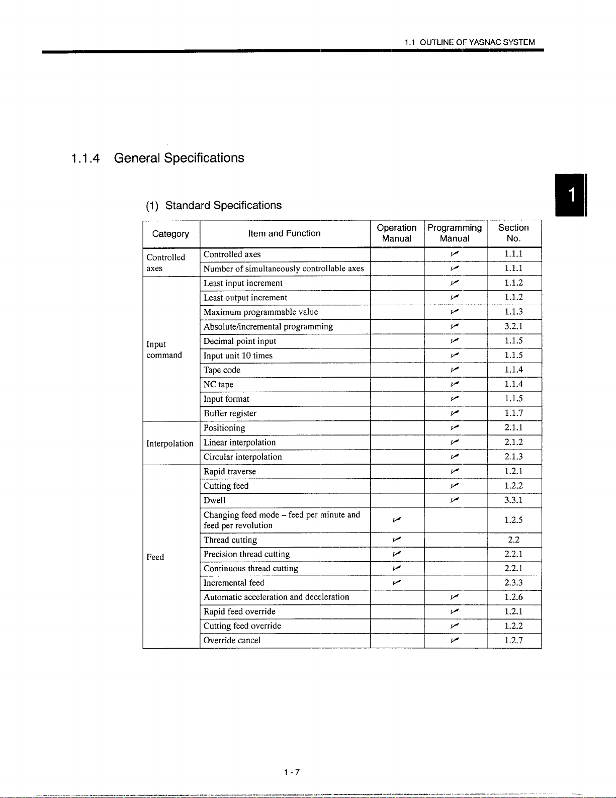
1.1.4
General
(1)
Controlled
axes
Interpolation Linearinterpolation
Specifications
Standard Specifications
Category
Controlledaxes
Numberof simultaneouslycontrollableaxes
E%%E=-----+----H*
Absolutehncrementalprogramming
~--t---t-+--w--
~--t--+--+-t+i
Positioning
Circularinterpolation
Rapidtraverse
“emand’unc’i0n7.-um
--m
=lSa
Feed
Changingfeed
feedperrevolution
mode – feedperminuteand
v
I
I
E=%=i----+-+---+-*
Icontinuous threadcutting
Automaticaccelerationanddeceleration
~--t-+-Y=t+w
Overridecancel
1-7
_----L-
IJ=I
..——.———-. .. .——
1.2.5
I
\
2.2.1 I
V
1,2.7
... ...-.—. .
I
Page 25
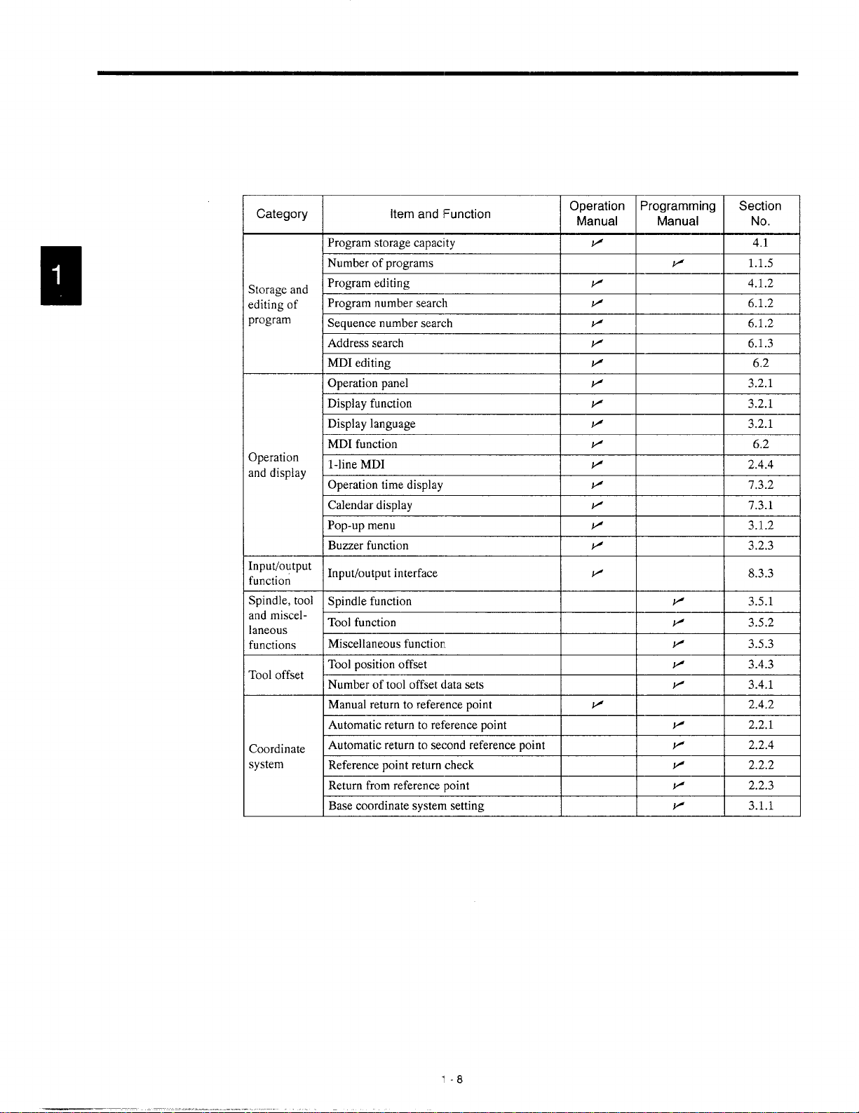
Category
Storageand
editingof
program
Operation
anddisplay
input/output
function
Spindle,tool
andmiscellaneous
functions
Tooloffset
Coordinate
system
Item and I=unction
Program storage capacity
Numberof programs
Programediting
Programnumbersearch
Sequencenumbersearch
Addresssearch
MDIediting
Operationpanel
Displayfunction
Displaylanguage
MDIfunction
l-line MDI
Operationtimedisplay
Calendardisplay
Pop-upmenu
Buzzerfunction
Input/outputinterface
Spindlefunction
Toolfunction
Miscellaneousfunction
Toolpositionoffset
Numberof tool offsetclatasets
Manualreturnto referencepoint
Automaticreturntoreferencepoint
Automaticreturntosecondreferencepoint
Referencepointreturncheck
Returnfromreferencepoint
Basecoordinatesystemsetting
Operation Programming
Manual Manual
v
v
P
v
1=
v
v
P
v
P 3.2.1
v
P
P
v 7.3.1
K
Y
P 8.3.3
P
v
v
P
P
P
v
v
P
v
v
Section
No.
4.1
1.1.5
4.1.2
6.1.2
6.1.2
6.1.3
6.2
3.2.1
3.2.1
6.2
2.4.4
7.3.2
3.1.2
3.2.3
3.5.1
3.5.2
3.5.3
3.4.3
3.4.1
2.4.2
2.2.1
2.2.4
2.2.2
2.2.3
3.1.1
1-8
Page 26
1.1 OUTLINE OF YASNAC SYSTEM
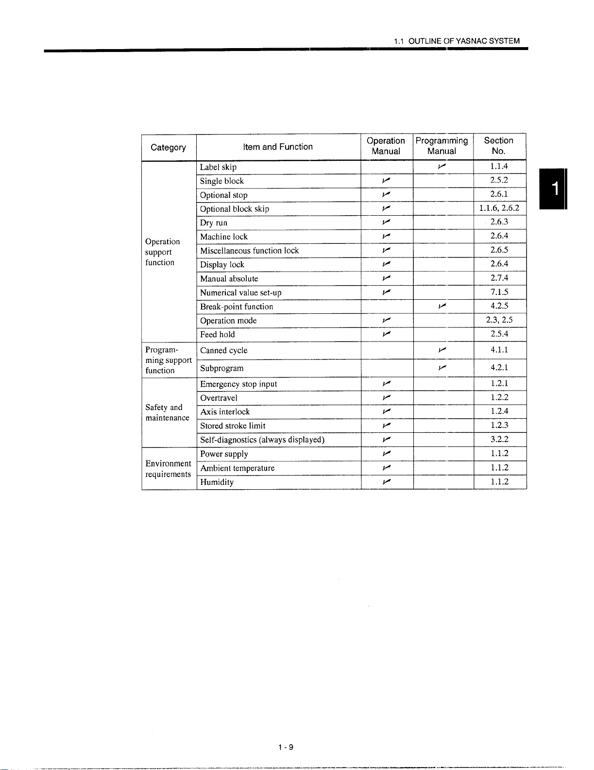
Category
3peration
;upport
function
Programmingsupport
function
Safetyand
maintenance
Environment
requirements
Item and Function
Label skip
Singleblock
Optionalstop
Optionalblockskip
Dryrun
Machinelock
Miscellaneousfunctionlock
Displaylock
Manualabsolute
Numericalvalueset-up
Break-pointfunction
Operationmode
Feedhold
Cannedcycle
Subprogram
Emergencystopinput
Overtravel
Axisinterlock
Storedstrokelimit
Self-diagnostics(alwaysdisplayed)
Powersupply
Ambienttemperature
Humidity
Operation Programming
Manual
Manual
v’
P 2.5.2
v 2.6.1
P 1.1.6,2.6.2
P 2.6.3
v 2.6.4
v
v
v 2.7.4
v 7.1.5
—
w
v
P 2.5.4
P
~
v 1.2.1
.—
P 1.2.2
v 1.2.4
v 1.2.3
v
v
v
F 1.1.2
—
Section
No.
1.1.4
2.6.5
2.6.4
4.2.5
2.3,2.5
4.1.1
4.2.1
3.2.2
1.1.2
1.1.2
1-9
— .——. .- .,-!, ,—.—.—-..—. ——-.
Page 27
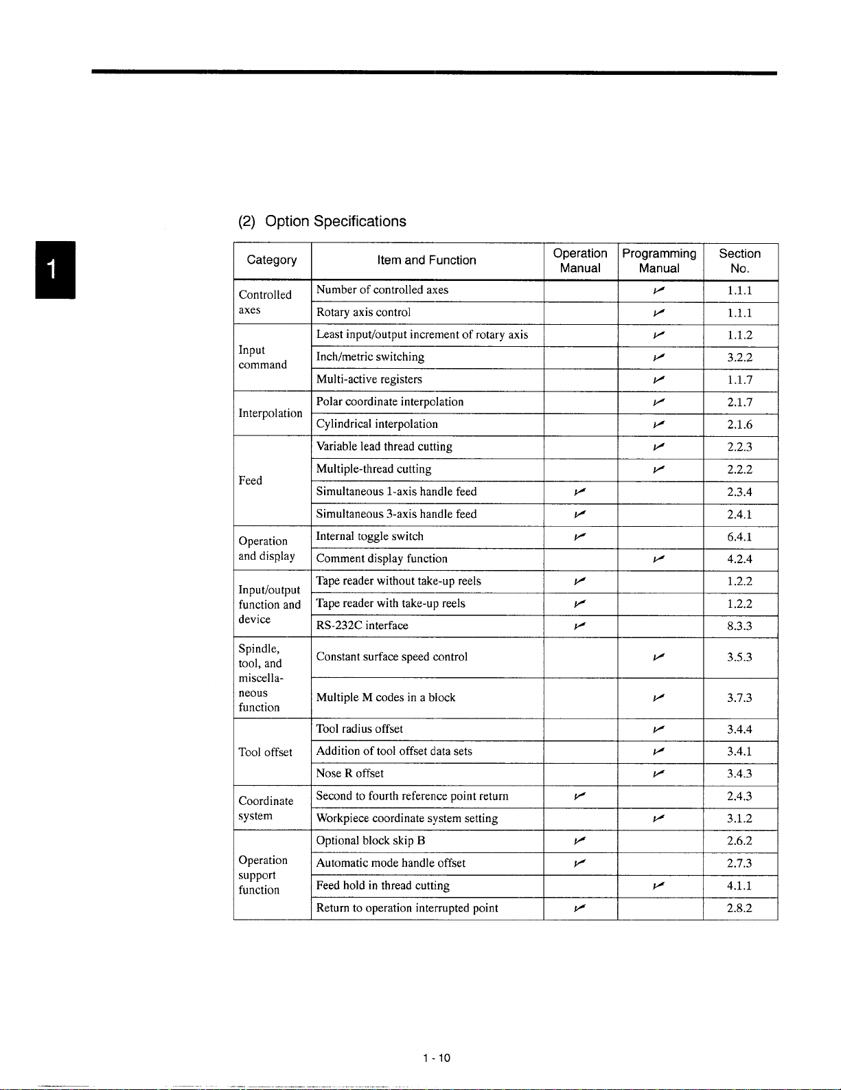
(2) Option Specifications
Category
Controlled
axes
Input
command
Interpolation
Feed
Operation
anddisplay
Input/output
functionand
device
Spindle,
tool,and
miscellaneous
function
Tooloffset
Coordinate
system
Operation
support
function
Item and Function
Number of controlled axes
Rotaryaxiscontrol I 1.1.1 I
Least input/output increment ofrotary axis \
Inch/metricswitching
Multi-activeregisters
Polarcoordinateinterpolation
Cylindrical interpolation
Variableleadthreadcutting
Simultaneousl-axis handlefeed
‘“’tip’e-threadc”tting~
Simultaneous3-axishandlefeed
Internaltoggleswitch
Commentdisplayfunction
Tapereaderwithouttake-upreels
Tapereaderwithtake-upreels IF
RS-232Cinterface v
Constantsurfacespeedcontrol
MultipleM codesinablock
Toolradiusoffset
Additionof tool offsetdatasets
Nose R offset
Secondto fourthreferencepointreturn
Workpiececoordinatesystemsetting
OptionalblockskipB
Automaticmodehandleoffset
Feedholdin threadcutting
Returnto operationinterruptedpoint
-----H-
Operation
Manual
I
I
I
I
I
-+---+%
-++-=+
I
I
+-+-=-l
-R+---l
I
1.2.2
8.3.3
I
I
I
v
+
+--t-=l
I
I
1P I 2.4.3 I
I
1P
I
P
-+--+=+
v
3.5.3
I 3.1.2 I
1 2.6.2 I
I 2.7.3 I
1-1o
Page 28

1.1 OUTLINE OF YASNACSYSTEM
Category
CircularinterpolationbyR command
CornerroundingbyRcommand
Program-
ming
support
function
Automation
support
function
Safetyand
maintenance StoredstrokelimitC
Multiple-repetitivecycle
Hole-machiningcannedcycle
Microprogram
I.Skipfunction
Toollifecontrolfunction
~1--+++--=-
‘t=’un’t’””-:ii:m
__l_~~
v’
v’ 2.1.4
P’
v’
v’ 4.4.1
a
I
1P
/
2.2.3
4.1.2
4.1.5
4.3.1 1
1-11
Page 29
1.2
PROTECTIVE
FUNCTIONS
1.2.1
1.2.2
Emergency Stop
Press the emergency stop button immediately if a problem occurs with the NC or system. The execution of all commands stops instantaneously when the emergency stop
button is pressed. Servo power supply of the NC is shut OFF and dynamic broke is applied
to stop all mechanical movement. In the emergency stop state, the NC is in the alarm state
“3002”. In the state the emergency stop signal input (CN02-19 pin on JANCD-JCP03 board)
is “opened”, the NC stops the entire operation, and turns OFF SVMX (CN2-17 pin on
JANCD-JCP03 board) and BKX (CN-18 pin on JANCD-JCP03 board).
overtravel
The overtravel function stops axis feed operation when an axis reaches the travel limit; for
the detection of travel limit, a limit switch and a dog are used and if an axis reaches the travel
limit, the limit switch outputs a signal and the function stops axis feed operation in response
to this input. The axis reached and stopped at the travel limit can be moved manually
into the axis movable range.
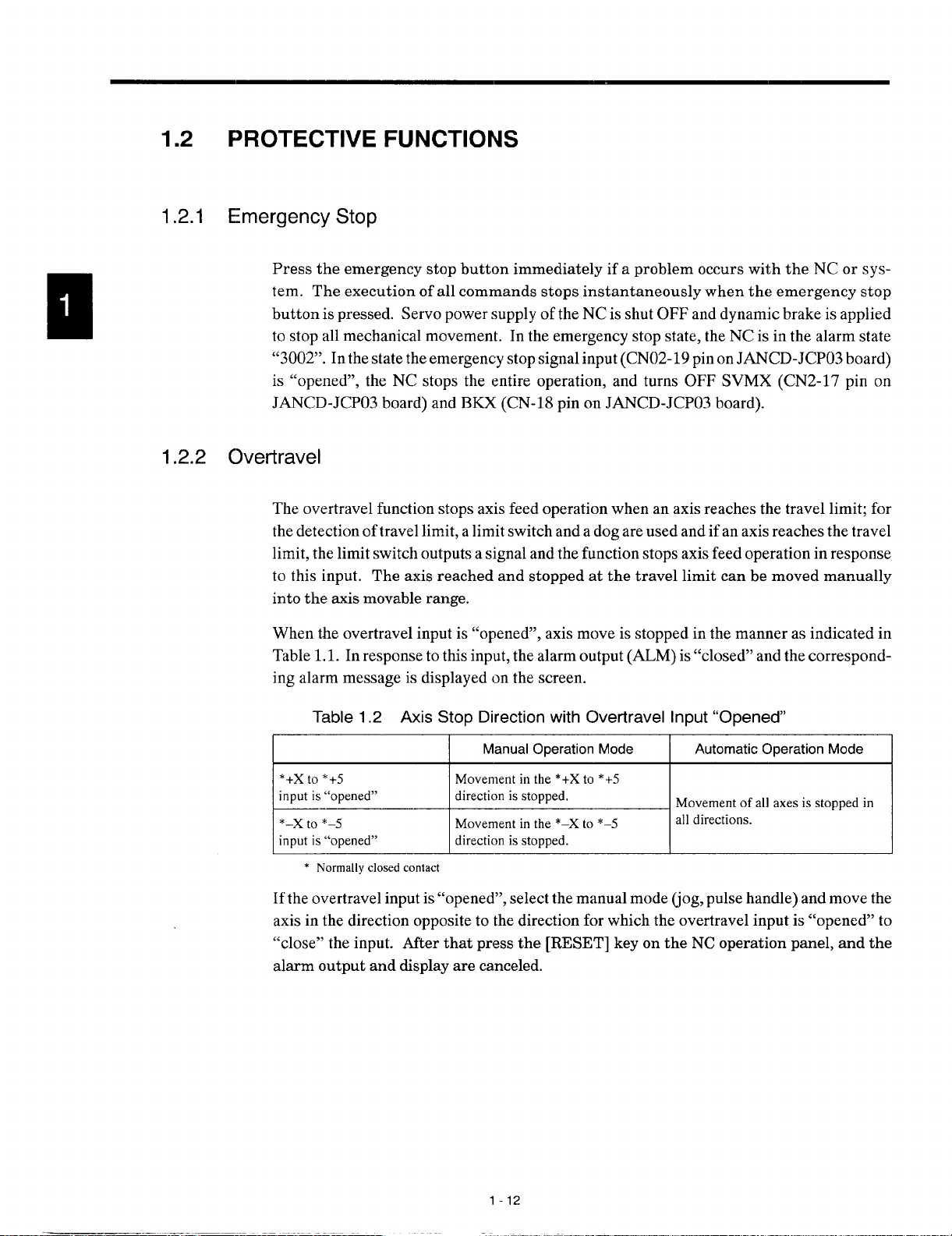
When the overtravel input is “opened”, axis move is stopped in the manner as indicated in
Table 1.1. In response to this input, the alarm output (ALM) is “closed” and the correspond-
ing alarm message is displayed on the screen.
Table 1.2 Axis Stop Direction with Clvertravel Input “Opened”
I I
Manual Operation Mode
Automatic Operation Mode
I
Movementof all axesis stoppedin
I
H&alldirectiOn
* Normally closedcontact
If the overtravel input is “opened”, select the manual mode (jog, pulse handle) and move the
axis in the direction opposite to the direction for which the overtravel input is “opened” to
“close” the input. After that press the [RESET] key on the NC operation panel, and the
alarm output and display are canceled.
1-12
Page 30
—1
1.2 PROTI:CTIVE FUNCTIONS
1. After the occurrence of an alarm due to the “open” of the overtraval input, the M,
S, and T code read output signals (MF, SF, and TF) are not turmd OFF.
2. If it is necessary to interrupt the operation called by M, S, and/or T code, set the
interlock by an external sequence.
3. The alarm numbers at the occurrence of overtravel are 2001 to 2035. If the over-
travel alarm occurs, axis move is stopped. Note that the servo is Ilot turned OFF.
M
—.
1.2.3 Stored Stroke Limit
To ensure improved safety in operation, the function prevents axes from l>ntering the preset
entry prohibited areas both in manual and automatic operation.
(1) Stored Stroke Limit A
The area either inside or outside the boundary specified by parameters or either G36 or
G38 is defined as the entry prohibited area. If an axis enters the defined entry prohibited
area, an alarm (“2011” to “2015”) occurs. By the setting of “pm500(j D6 = l“, the entry
of an axis into the entry prohibited area does not cause an alarm and only the stroke
check monitor output signal (#3640, #3641) is output.
Entry prohibited area
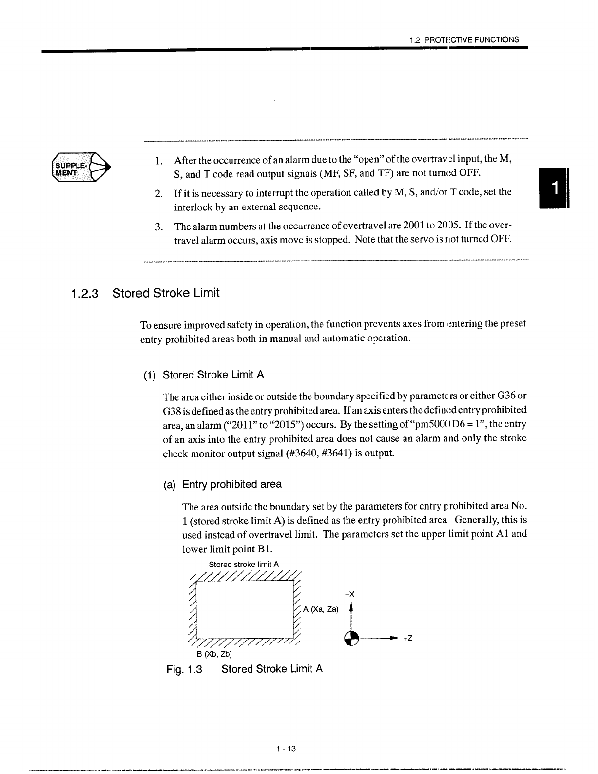
The area outside the boundary set by the parameters for entry prohibited area No.
1 (stored stroke limit A) is defined as the entry prohibited area. Generally, this is
used instead of overtravel limit. The parameters set the upper limit point Al and
lower limit point B1.
Stored stroke limit A
_-——
[z~AVaz@~ ~+z
B (Xb, Zb)
Fig. 1.3 Stored Stroke Limit A
1-13
—... .....—
.—=. ——— m——... — ‘. !-,!.—. .—. —..,
———. -
Page 31

(b) Setting the stored stroke limit A check
Whether or not the stored stroke limit A is made valid is set for the individual axes
using the following parameters.
Table 1.3 Valid/invalid of Stored Stroke Limit A Check
E==3=s
pm6002 DO pm6002 D1 pm6002 D2 pm6002 D3
BitSetting
t--
(c) Parameters for specifying the boundary of stored stroke limit A
Table 1,4 Parameters for Specifying the Boundary of Stored Stroke Limit A
Name 1st Axis
Axis
Boundary(+):PointA pm6901
Boundary(–):Point B pm6911 pm 6912 pm 6913 pm 6914
(2) Stored Stroke Limit B (G36 to G39) *
The area either outside or inside the boundary set by parameters or by the commands
in a program is established as the entry prohibited area. The boundary is set with the
coordinate values in the machine coordinate system. Whether the entry prohibited area
is established outside or inside the boundary can be determined by the setting for a parameter. The function is made valid upon completion of the reference point return after
turning ON the power.
2“’%’s
0: Executesstoredstrokelimitcheck.
1: Doesnotexecutestoredstrokelimitcheck.
2nd Axis 3rd Axis
pm6902
‘“w’
pm6903 pm6904
‘thMs5thh
AXi’
4th
pm6002 D4
5th AXi’
pm6905
pm6915
Table 1.5 G Code Used to Turn ON/OFF the Stored Stroke Limit B Function
G Code Function Group
G36 TurningONthestoredstrokelimitB, C (entryprohibitedareasNo, 07
2 to No.5)
G37
G38
G39 TurningOFFthestoredstrokelimitC (entryprohibitedareaNo. 3) 08
.
TurningOFFthestoredstrokelimitB,C(entryprohibitedareasNo.
2 to No.5)
TurningONthestoredstrokelimitC (entryprohibitedareaNo.3)
1-14
07
08
Page 32

1.2 PROTECTIVE FUNCTIONS
●
In addition to the stored stroke limit A, stored stroke limits B and C can be added.
●
With the stored stroke limits B and C, set the boundary of the area and inside
or outside the boundary by parameters.
1.2.4
●
According to the setting fc)rthe parameter, either of stored stroke limits B and
C can be made valid.
●
For details of the stored stroke limit B, refer to 4.2.3 “Sul~program Call Up
Function (M98, M99)” in the PROGRAMMING MANUAL.
Interlock inputs
The interlock input is the signal used to disable axis movement, and is pro!:ided for each axis.
● When an axis is interlocked during movement, it is stopped after deceleration.
● When the interlock is released, the axis continues moving to complete the re-
maining commands. Upon completion of the command:,, the program advances to the next block.
● For simultaneous three axis interpolation commands, interpolation operation
is disabled if one of these two or three axes is interlocked.
YASNAC
—-—.
1
cl---l+’
ml
*C
d
Fig. 1.4 Interlock Inputs
1-15
Axis interlock
z
——.——. —.— ..—..—
Page 33

BASIC OPERATION OF YASNAC
Chapter 2 describes various kinds of operations including
power ON procedure: manual operation, and automatic operation,
2.1 GENERAL FLOW OF OPERATION . ~. ..2-3
2.2 INSPECTION BEFORE TURNING
THE POWERON . . . . . . . . . . . . . . . . . ...2-4
2.2.1 inspection of the NC IJnit . . . . . . . . . . . . . . ...2-6
2.2.2
2.2.3
Inspection of the Tape Reader . . . . . . . . . . . . . 2-7
Preparation before Turning the Power
CIN . . . 2-8
2.3 TURNING TI+E POWER ON AND
INSPECTION A17ER POWER ON . . ...2-9
2.3.1 Procedure for Turning the Power ON . . . . . . . 2-9
2.3.2 Checking the Motors ‘for Abnormalities . . . . . 2-10
2.3.3
2.3.4
2.4 MANUAL OF)ERATION (l) . . . . . . . . ...2-15
2.4.1 Manual Rapid Traverse (RAPID) . . . . . . . . . . 2-15
2.4.2 Jog Fef?d (JOG) . . . . . . . . . . . . . . . . . . . . . . . .2-16
2.4.3 Step Feed (STEP) . . . . . . . . . . . . . . . . . . . . .2-16
2.4.4 Handle Feed (HANDLE) . . . . . . . . . . . . . ...2-17
Procedure for Turning the Power OFF . . . . . 2-11
inspection of the Battery . . . . . . . . . . . . . . . 2-12
—-— —.. .—. ———. —.. ——. — .—. -.. .’...—
2-1
. .. ..—. . ..—
—.. .—.,.—-. —.-——..—
Page 34

2.?5 MANUAL OPERATION(2) . . . . . . . . ...2-18
2.5.1 Simultaneous 3-axis Handle Feed * . . . . . . . 2- 18
2.5.2 Manual Reference Point Return . . . . . . . . . 2-19
2.5.3 Manual Reference Point Return
to the Second Reference Point* . . . . . . . . .
2-22
2.5.4
l-line MDl . . . . . . . . . . . . . . . . . . . . . . . . ... ..2-23
2.6 AUTOMATIC OPERATION (1) . . . . . ...2-24
2.6.1 Preparation of Automatic Operation . . . . . . . 2-24
2.6.2 Memory Operation . . . . . . . . . . . . . . . . . . . ...2-26
2.6.3 MDI Operation . . . . . . . . . . . . . . . . . . . . . . ...2-27
2.6.4 Feed Hold . . . . . . . . . . . . . . . . . . . . . . . . . . ...2-28
2.6.5 Override . . . . . . . . . . . . . . . . . . . . . . . . . . . . ...2-29
2.7 AUTOMATIC OPERATION (2) . . . . . . . .2-31
2.7.1 Optional Stop . . . . . . . . . . . . . . . . . . . . . . . ...2-31
2.7.2 Optional Block Skip . . . . . . . . . . . . . . . . . . ...2-31
2.7.3 Dry Run . . . . . . . . . . . . . . . . . . . . . . . . . . . . ...2-32
2.7.4 Machine Lock . . . . . . . . . . . . . . . . . . . . . . . ...2-33
2.7.5 Auxiliary Function Lock . . . . . . . . . . . . . . . . . . 2-33
2.7.6 Feed Hold in Thread Cutting*.. . . . . . . . . . . 2-34
2.8 OPERATION INTERVENTION
DURING AUTOMATIC OPERATION ., .2-35
2.8.1 Manual Operation Intervention
during Automatic Operation . . . . . . . . . . . . . . 2-35
_--- ...—.
2.8.2 MDI Operation Intervention
during Automatic Operation . . . . . . . . . . . . . . 2-36
2.8.3 Automatic Handle Mode Offset* . . . . . . . . . . 2-37
2.8.4
Manual Absolute . . . . . . . . . . . . . . . . . . . . . ...2-38
2.9 AUTOMATIC OPERATIONS
AT EN14ANCED LEVEL ., . . . 2. . . . . ...2
2.9.1 Fleturn to Setup Point . . . . . . . . . . . . . . . . ...2-40
2.9.2 Return to the Operation Interrupted Point* . 2-40
2.9.3 Saving the Present Position Data . . . . . . . . . 2-42
2.9.4 Program Restart . . . . . . . . . . . . . . . . . . . . ...2-43
2-2
-40
Page 35

2.1 GENERAL FLOW OF OPERATION
2.1
GENERAL FLOW OF OPERATION
The operation procedure usually followed for daily operation is indicated in Fig. 2.1. This
Chapter gives explanation on these operation items.
MODE SELECT
wchecking’heNc”ni’
&-
ConfirmingREADY signal ON
Setting the switches
on the operation panel
~ CYCLE START ON
$-
-
- SINGLE-BLOCK
‘tc,
RESET ON
FEED HOLD or
SINGLE-EILOCK ON
Manual operation
intervention
k
-__!ic= ---------”:
Zero point
return operation
I
--vF _...._:
Manual or by G28 ,
I
Pitch error compensa- ~
tion,
Stored stroke limit ON/
L
Preparation for
automatic operation
Positioning
at the start point
$-
$-
K
CYCLE START ON
SINGLE-BLOCK ON
MDI operation
intervention
CYCLE S-I”ART ON
Setting NC tape
J
1
LoadingNCprogramfromtape,
letit.g:toredN;programand
executingprogramnumbersearch
1
I
(!!!!
Preparation for
turning
*rrence
Checking tool
offset amounts
I
I
Fig. 2.1 Operation Procedure
I
I
r
.4-
OFF the power
End of mtichining
- CYCLE START OFF
- Checking for alarm
2-3
——. ——- . . ..- .——. -.- ——, - —.
—... ..—.-.—--— .———..—
.-. ——-—
Page 36

2.2 INSPECTION BEFORE TURNING THE POWER ON
Before turning the power ON for YASNAC J300, it is necessary to carry out inspection to
ensure safety. If the power is turned ON while the system has troubles, it could cause malfunctioning of the system itself as well as hazards to the operators. Make sure to carry out
daily inspection before turning the power ON.
@ WARNING
Always turn the power OFF (including the primary power supply) before carrying
~
out daily inspection.
Carrying out the inspection with the power ON may lead to electric shock.
D Wait 5 minutes after turning the power (including the primary power supply) OFF
before removing or replacing any unit or part.
Failure to observe this warning may lead to electric shock and product failure.
o Do not
Failure to observe this warning may lead to electric shock or device malfunction.
D Immediately after switching the power OFF, the product retains some electric
charge. Do not touch any parts which are live when the power is ON for 5 min-
utes after switching the power OFF.
Failure to observe this warning may lead to electric shock or device malfunction.
● Do not damage cables, subject them to excessive stress, or pinch them.
Excessive load on cables may cause electric shock.
o When the unit is turned ON, never touch its rotating parts,
Failure to observe this warning may result in personal injury.
c Never modify the product.
Failure to observe this warning may result in electric shock, fire, or product failure.
touch any unit, terminals, etc., while the power is ON.
Page 37

2.2 INSPECTION BEFORE TURNING THE POWER ON
~ CAUTION
To prevent personnel other than those involved in maintenance and inspection
I
work from turning ON the power while maintenance and inspection is in progress, place signs stating “Do not turn the power on” or words to ‘lhat effect at the
primary power supplies of related control panels and other relevant locations.
Failure to observe this caution may lead to electric shock.
J Electronic devices such as C MOS ICS are used on the control boards. If you
touch them with your bare fingers the static electrical charge in your body could
destroy them; care must be taken when handling these devices, Before han-
dling these devices for maintenance purposes, first discharge the static electric-
ity in your body by touching a grounded metal device.
Failure to observe this caution could lead to injuries and product failure.
D Do not install or remove boards, wiring, connectors, etc., while the power is ON.
Failure to observe this caution could lead to electric shock, product failure, and malfunction.
o Do not let foreign matter such as electric wire scrap enter the unit.
Failure to observe this caution may result in fire, product failure or malfunction.
I Be sure to check the following points on completing maintenance and inspection
work.
● Check that all fastening bolts are tightened.
● Check that no tools or other objects have been left inside the conl.rol panel.
● Check that the control panel door is closed properly.
Failure to carry out these checks may lead to electric shock, injuries, fire, and malfunction.
~ Never attempt to disassemble or modify units or devices insidls the NC unit.
Failure to observe this caution may lead to fire, product failure, or malfunction.
o Do not change the set values of the devices, variable resistors, etc., in the con-
trol panel.
Failure to observe this caution may lead to fire, product failure, and malfunction.
——— ——-. — .—.. ---- -
2-5
.———, . —. —.. .-,, ,—.— —-. —.—. -.
Page 38

2.2.1 Inspection of the NC Unit
In this subsection, the items to be inspected before turning ON the power are indicated for
the standard NC box supplied by Yaskawa. For the control box specific to the machine tool,
refer to the manuals published by the machine tool builder.
(1) inspecting the Doors
Make sure that the doors are securely closed before turning the power ON.
The NC box is completely shielded to keep outside air out to protect the precision de-
vices in the NC box from oil mist or other airborne foreign matter. The doors of the NC
box must always be kept closed.
(2) Inspecting the Shielding Parts
Inspect the shielding parts in the NC box every month for gaps and/or damages.
@ Open the doors and check the packings which are installed around the door for
damage.
@ Inspect the inside of the NC box for abnormal contamination. If the inside is
abnormally dirty, clean it immediately after locating the cause of contamination.
@ Lock the doors securely and inspect the doors to make sure that there are no
gaps.
By carrying out the inspection indicated above at regular intervals, performance of
YASNAC J300 can be maintained for a long period.
2-6
Page 39

2.2 INSPECTION BEFORE TURNING THE POWER ON
——
2.2.2
Inspection of the Tape Reader
If the tape reader is dirty or does not operate smoothly, it could cause mal:~unctioning of the
NC. Inspect and clean the tape reader from time to time.
Tape hol
Reading head
Fig. 2.2 Tape Reader
Clean the glass in the reading head by removing tape chips and dust with a soft
brush. If oily stain is found, wipe it off with clean gauze 01soft cloth soaked
with absolute alcohol. Clean both the tape guide face and tape holder at the
same time.
Fig. 2.3
If dust is found on the LED face in the upper light source, clean it with soft
brush.
For the tape reader equipped with 6-inch cm8-inch tape take-up reels, if tension
arm movement seems to be heavy, apply a small amount of machine oil to the
shaft base portion.
C)*
Supply oil here
o
\
/
\
\
8-inch Take-up Reel
Tension arm
2-7
----- .. —
,—.—.
.. .—..—.. —.—— ..—
——-—.
Page 40

.——_, ._.. __. __. _.-- . .. ._______ ——
suPP&E-
klENT
D
If a problem occurs with tape winding or tape feed operation with the tape reader
equipped with 8-inch tape reels, open the front door, and clean the area around the photocoupler located near the reel drive motor.
——— —.———-——.—,——-.———
2.2.3 Preparation before Turning the Power ON
Before turning the power ON, confirm the following items.
● Make sure that both the front and rear sides of the NC unit are closed. If the
door is open or if there is a gap between the door and the box panels, securely
close the door using the door lock.
● Carry out the inspection for the machine and machine related controllers ac-
cording to the instructions given in the manuals published by the machine tool
builder.
—.-—-.., --. -.—-..-.——---------
—.. ..-. ..-—. — - —
:2.8
Page 41

2.3 TURNING THE POWER ON AND INSPECTION AFTER POWER ON
2.3 TURNING THE POWER ON AND INSPECTION AFTER
POWER ON
In this section, the procedure to be used for turning the power ON is explained. Inspection
that must be conducted after turning the power ON is also described.
@ WARNING
2.3.1
. Be sure to turn the power OFF before replacing the battery.
Failure to observe this warning may lead to electric shock and product failure
~
●
Replace fuses and batteries with the designated products.
Failure to observe this caution may result in fire or product failure.
●
Use the product with the “System Number Switch” of the CPU set to ‘(O”.
Use while set to another number may lead to malfunction.
●
Wait at least 2 seconds after turning the power OFF before turning it ON again.
Failure to observe this caution may lead to malfunction.
CAUTION
I
Procedure for Turning the Power ON
Turn the power ON in the following procedure.
@) Make sure that the power is supplied to the NC unit from an external power
source.
“7
___l__l
ml
Press the POWER ON button on the NC operation panel. Control power is
turned ON and the cooling fan starts rotating.
Make sure that air is flowing out at the upper part on the side of the NC unit.
In approximately 20 seconds, the control is ready for turning ON the servo
power (alarm code 3000).
Press the POWER ON button once again.
The servo power is turned ON. When the machine is read y for operation, the
NC enters the ready state.
When the power is correctly turned ON to the NC unit, the NRD (NC ready)
signal is output.
2-9
.——-— . ..... ——=. —
,— —,.. —.. ,.., ,—.—. —.. ——— —..
Page 42

When the power is turned ON at the machine side in response to the NRD signal, the MRD (machine ready) signal will be returned to the NC. The READY
lamp goes on when the MRD signal is returned. Note that the READY lamp
is not used with some types of machines.
When the NC unit enters the ready state, the alarm message displayed on the
screen will go off.
If the NC unit fails to enter the ready state, locate the cause by referring to Section 7.2, “ALARM DISPLAY JOB”, and take appropriate measures. For turning the power ON, there are items that must be inspected at the machine side
in addition to the NC unit related items. For such items, refer to the manuals
published by the machine tool builder. ‘
POWER ON POWER ON
44
–JAPP,OX, :
;- ;
—
—
.~.
—
—
\
Control power supply
Control ready
Servo power supply
NRD (NC ready)
Machine power supply
MRD (machine ready)
Alarm code: “3000 “21 90;’ “Blank”
Fig. 2,4 Power ON Sequence
2.3.2 Checking the Motors for Abnormalities
Check the motors for their operation. If abnormal vibration or noise is found, turn OFF the
power and contact the maintenance personnel.
::
,,
2-1o
Page 43

2.3 TURNING THE POWER ON AND INSPECTION AFTER POWER ON
2.3.3 Procedure for Turning the Power OF:F
Turn the power OFF in the following procedure.
Make sure that the CYCLE START lamp on the machine operation panel is
OFF with the machine stopped.
Make sure that there is no alarm message displayed on the CRT screen. If an
alarm message is displayed, locate the cause by referring to Section 7.2,
“ALARM DISPLAY JOB” and take appropriate measures to clear it.
Carry out inspection necessary for turning the power OFF at the machine side.
For details, refer to the mimuals published by the machine tool builder.
Press the EMERGENCY STOP button on the machine operation panel to turn
OFF the servo power.
Press the POWER OFF button on the NC operation panel to shut off the power
to the control panel.
Turn the power supply to the NC OFF by turning OFF such as a circuit breaker.
Control power supply
Control ready
NRD (NC ready)
Machine
M.D(.achinerea(~Q-.–.
READY lamp
2.5 Power OFF Sequence
Fig.
~—{
+-—.—
power
----1 / —.
Alarm: “ENank”
EMERGENCY STOP POWER OFF
; ---——l___
IIL ! -
,-
“3002 i
2-11
..-, -—..——. — .—..——. -—. ———.—
——-—
Page 44

2.3.4 Inspection of the Battery
After turning the power ON, check the CRT screen if “BAT’ message is blinking at the lower
right area. If it is displayed, it indicates that the battery is weakening. The battery must be
replaced within one month. If the display of “BAT’ message is given, make sure to leave
the NC unit power ON at least
Standard batteries cannot be used. For a spare battery, contact your Yaskawa representative.
Battery type: ER6VC3, Parts code: BA507
olme hour every three days.
rmsmr
BAT
Eg:
Battery alarm indication
Connector
The location of battery and related indicator (LED) is shown in Fig. 2.5.
(1) Checking the Battery Which Needs Replacing
Follow the procedure indicated below to check whether or not battery must be replaced.
Press the POWER OFF button.
If a door interlock switch is installed, place the door interlock key in the OFF
position. This makes power ON possible with the door opened.
Open the door so that the front part of the NC unit is visible.
Press the POWER ON button once again.
Check the red LED on the JCPO1 board. If it is lit, the battery must be replaced.
2-12
Page 45

2.3 TURNING THE POWER ON AND INSPECTION AFTER POWER ON
—1
Red LED—
[
w
JCPO1 JOPO2
Battely
JCP04
Battery cover
—
L,
E
Fig. 2.6
!
1
1
1
1
Arrangement of Battery and Indicator Lamp (LED)
2-13
Page 46

(2) Replacing the Battery
the battery quickly in the following procedure.
Turn the power OFF.
Remove the battery cover by prying it up with a screwdriver. Then, remove
the battery from the holder.
Fit the new battery in the holder and insert the connector. Although the connector may be inserted in either direction, it must be securely inserted. Other-
wise, the power will not be supplied by the battery. (See Fig. 2,7.)
\\ I//
POINT
Q
(Correct) (Correct)
Fig. 2.7
1. If the red LED remains lit after replacing the battery, the connector might be inserted incorrectly or the battery might be faulty.
2. Power OFF operation is allowed a few seconds after turning the power ON.
3. After turning the power OFF, replace the battery quickly. If the NCunit is left with
the battery removed, the clata stored in the memory could be lost.
4. If the NC unit has two battery packs, replace both of battery packs at the same
time. Note that the date of manufacture of the battery packs to be installed newly
should be as close to each other as possible. If the battery packs manufactured
in different years are used, the service lives of them will be shortened and in the
worst case, the life will be that of a single pack.
Connecting the Battery Connector
Turn the power ON.
Make sure that “BAT” is not blinking on the CRT screen and that the red LED
in the board is OFF,
(Incorrect)
——— ——
2-14
Page 47

2.4 MANUAL OPERATION (1)
This section describes general explanation on manual operation. To move an axis manually,
select the operation mode of wID, JC)G, STEP or HANDLE with the MODE SELECT
switch on the machine operation panel.
2.4.1 Manual Rapid Traverse (RAPID)
An
axis can be moved at a rapid traverse rate. Follow the procedure indicated below.
Select the rapid mode by placing the MODE SELECT switch on the machine
operation panel in the RAPID position.
MEM
Mc)l
2.4 MANUAL OPERATION (1)
TAPE
HANDLE
STEP
JOG
e
m
RAPID
Select the feedrate to be used for axis feed operation by the RAPID TRAVERSE RATE OVERRIDE switch on the machine operat ion panel.
Override setting is possible in four steps of 100%, 50%, 25’%,and Fo. The feedrate corresponding to the ~settingat 100%, 50%, and 25% isset for parameters
pm2801 to pm2805. For the setting at F(),feedrate set for parameter pm2447
is used.
Optionally, F1 and Fz positions are selectable. Feedrate to be selected accord-
ing to the switch setting at F1 and F2 is set
On the machine operation panel, press the JOG button that corresponds to the
axis and the direction in which the axis should move. The ax is moves at a rapid
traverse rate while the button is held pressed.
JOG
+x
+C +Z
“
Ifor parameters pm2448 and pm2449.
❑ IEIIID
mm
2-15
Page 48

2.4.2 Jog Feed (JOG)
It is possible to move an axis in the jog feed mode. Follow the procedure indicated below.
@) Select the jog mode by placing the MODE SELECT switch on the machine
operation panel in the JOG position.
@ Select the feedrate with the JOG FEEDRATEswitch on the machine operation
panel.
● Feedrate can be selected from 32 steps, with actual feedrates of individual set-
ting positions set for parameters pm2400 to pm2431. The actual number of
steps and feedrates selectable by the JOG FEEDRATE switch vary depending
on the machine model. For details, refer to the manuals published by the machine tool builder.
@ Press the JOG switch corresponding to the axis to be moved and the required
axis move direction.
@ The axis moves at the selected feedrate while the JOG switch is held pressed.
2.4.3 Step Feed (STEP)
Manual step feed operation is pcs.sible. Follow the procedure indicated below.
Select the step mode by placing the MODE SELECT switch on the machine
operation panel in the STEP position.
Select the feed distance per step with the MANUAL PULSE MULTIPLY
switch on the machine operation panel.
Metric system :
Inch system
0.001,0.01,0.1, 1.0,10.0, 100.0 mm (per step)
: 0.0001,0.001,0.01,0.1, 1.0, 10.0 inch (per step)
Press the JOG switch corresponding to the axis to be moved and the required
axis move direction.
Each time the JO(3 switch is pressed, the selected axis moves in the selected
direction by the set feed distance per step.
2-16
Page 49

2.4.4 Handle Feed (HANDLE) *
When the NC is equipped with a manual pulse generator, pulse handle fetid opemtion is possible. Follow the procedure indicated below.
Select the handle mode by placing the MODE SELECT sw;tch on the machine
operation panel in the HANDLE position.
Select the axis to be movedby the HANDLEAXIS selection switch on the machine operation panel.
With the MANUAL PULSE MULTIPLY switch on the machine operation
panel, select the axis feed distance per pulse (one division of the pulse handle).
2.4 MANUAL OPERATION (1)
Clockwise rotation:
Counterclockwise direction:
Metric system
: 0.001,0 .01,0.1 mm (per division)
In the positive direction
In the negative direction
Inch system : 0.0001,0.001,0.01. inch (per division)
Turn the pulse handle. The axis moves in the positive or negative direction
according to the direction in which the pulse handle is turned.
2-17
Page 50

2.5 MANUAL OPERATION (2)
This section describes manual operations carried out in daily production using the manual
operation functions explained in 2.4 “MANUAL OPERATION (l)”.
2.5.1 Simultaneous 3-axLs Handle
By installing the pulse handle for the individual axes, it is possible to move three axes among
the X-, Z-, and C-axis simultaneously. Follow the procedure indicated below.
1st HANDLE AXIS
c
Xj-w
o
1st HANDLE AXIS
—
0
D
Fig. 2.8
z
Q
i-
0
Simultaneous 3-axis Pulse Handle Feed
Feed *
2nd HANDLE AXIS
c
XA z
e
o
2nd HANDLE AXIS
+
0
o
01
MANUAL PULSE MULTIPLY
xl 00
xl o
xl *
@
xl 000
Xlo,ooo
Xloo,ooo
3rd HANDLE AXIS
3rd HANDLE AXIS
—
i-
0
0
D
@ Select the handle mode by placing the MODE SELECT switch on the machine
operation panel in the HANDLE position.
@ Select the axis feed distance per graduation of the pulse handle with the
MANUAL PULSE MULTIPLY switch on the machine operation panel. This
switch is used in common for the three pulse handles.
@ Turn the pulse handle. The selected axis is movedin the positive or negative
direction according to the handle turning direction.
2-18
Page 51

2.5.2 Manual Reference Point Return
Axes can be returned to the reference point in manual operation. Follow the procedure indi-
cated below.
Select the rapid orjogmode by placing the MODE SELECT switch on the ma-
@
chine operation panel in the RAPID or JOG position.
Move an axis manually (manual rapid traverse or jog feed) lo a position away
@
from the reference point (within the reference point return enabled area).
When an axis is located in range A in Fig. 2.9, reference point return ca be
executed correctly.
Turn ON the REFERENCE POINT RETURN switch.
@
2.5 MANUAL OPERATION (2)
TERM?
D
Keep the JOG switch pressed corresponding to the axis to be returned to the
@
reference point and in the return direction. When the JOG switch is held
pressed, the corresponding axis starts moving in the same manner as ordinary
manual axis feed operation. When the axis reaches the deceleration point, feedrate is decelerated to a low feedrate and the axis stops automatically at the
reference point.
Upon completion of the reference point return, the REFERENCE POINT
@
lamp of that axis lights.
Rapid traverse rate
~<F@S2ce
I
Dog width ~ ~
la
J
I
-,
----
MnJL.l@L
Area A
Fig. 2.9 Manual Reference fsoint Return
+ Reference Point
e-
Aspecificpositioninthemachinecoordinatesystem. It is also called the machine zero POmt or the machine
preferencepoint.
~ FeedrateLSsignal
ItI
Zero-point signal
-1~—
I
i
i
F’oint C
Area B
—.—
—. —-- —-. ——-..—.—
2-19
——.. -.. ———. . . . ..
-. .. ..—. —.——.—
Page 52

\\ I//
POINT
Q
-————-,.———_ .———..————
1. Once the reference point return is completed, point C indicatedin Fig. 2.9 is stored
to the NC. Therefore, if reference point return is attempted while an axis is in area
B, an error occurs. In this case, the axis should first be returned to area A and then
the reference point return should be executed.
2. The axis for which reference point return has been completed can be moved in the
reference point return direction manually only if the reference point return switch
is turned OFF.
3. If commands have been read to the buffer area during automatic operation, manual reference point return must not be executed. If manual return operation is
executed, the data in the buffer area is cleared.
——.—.—
—
.—.
2-20
Page 53

SUPPLE-
MENT
(3
cm—l
Immediately after the power is turned ON, the axes start manual or automatic ref-
1.
2.5 MANIJAL OPERATION (2)
erence point return operation ind~ependent of the present axis posi tion. However,
reference point return cannot be executed correctly if the axis is located in area
B. In this case, the axis must bc returned to area A before exec~ting reference
point return.
If the MODE SELECT switch setting is changed while an axis is moving auto-
2.
matically to the reference point, an alarm (alarm 2141 to 2145 reference point return interruption error) occurs.
Reference point return cannot be executed when the MACHINE.; LOCK switch
3.
is ON.
With a rotary axis, it is possible to execute automatic reference point return as
4.
with a linear axis.
With a rotary axis, if it has been moved by more than
* 360.000° from the reference point established first, reference point return is
executed to the closest reference point in the preset direction of reference point
return.
The illustration below shows how the reference point return is executed from
points A and B. (The reference point return direction is determined by the setting
for pm4002 D3 and D4.)
–360 0
B’
~.
0
1
3600 7200
;’6 +
B
,
A
–720 “
Once the reference point return is completed, second and later reference point re-
5.
turn is executed at a high-speed mode. This is cidled “high-speed reference point
return”.
However, if the setting is so made to execute the reference point return
at a low speed (pm4003 D6 = 1), second and later reference point return is
executed at a low speed.
Feed rate
~z~
—.
Rapid traverse
+
._ —.- —.
Feedrate sequence
.—
2-21
—— . ..—. — -—. — ..—.—
...—-—.. .
Page 54

2.5.3 Manual Reference Point Return to the Second Reference Point*
The axes are automatically positioned at the second reference point. This operation allows
positioning at the second reference point independent of the present axis position, whether
it is in the negative side or positive side from the second reference position. Follow the procedure indicated below.
@ Select thejogorrapidmode byplacingthe MODE SELECT switch in the JOG
or RAPID position.
@ Turn ON the ZRN2 (second zero point return request) switch on the machine
operation panel.
@ Keep the JOG switch corresponding to the axis and direction of reference
point return. The corresponding axis is positioned at the second zero point at
the jog feedrate or rapid traverse rate according to the selected mode.
● If the ZRN2 switch is turned OFF while an axis is moving to the second refer-
ence point, the axis stops moving. To restart the second reference point return
operation, turn ON the ZRN2 switch and turn OFF the JOG switch having
been pressed once, then press it once again.
● If the JOG switch is pressed again to be turned OFF while the X-axis is moving
to the second zero :point, the axis stops moving. In this case, press the JOG
switch again to turn it ON, and the X-axis restarts moving to the second zero
point. With the Y- and Z-axis, this is also applied.
\\ I/,
POINT
1. If the JOG switches of [+] and [–] are pressed at the same time, the corresponding
axis stops moving since this operation is assumed to have turned OFF the JOG
switch.
Q
2. It is not allowed to use the first zero point return mode and the second reference
point return mode at the same time. If both input signals are ON at the same time,
both of the modes are invalid and neither jog nor rapid feed is executed. This feature is provided to ensure safety.
——————
3. If the NC is in either the machine lock state (including the machine lock for individual axes) or the Z-axis command disregard state, the second zero point return
operation cannot be executed. When a JOG switch is pressed under such state,
normal jog operation is performed.
4. With the axis for which second zero point return has been completed, manual axis
move operation is allowed only after the ZRN2 (second reference point return)
switch is turned OFF.
2-22
Page 55

;tJPl&LE-
(3
2.5 MANUAL OPERATION (2)
If the second zero point return input signal is turned ON in the state that the first
1.
zero point return has not been completed, the input is invalid and thesecond reference point return mode cannot be set.
2. In the second reference point return mode, input from the JOG switch [-X] ([-Z],
[-C]) is valid. If the mode is changed, the ZRN2 switch is assumtid to have been
turned OFF.
2.5.4 l-line MDI
During the execution of manual operaticm, it is possible to execute one b ~ockof a part program by directly entering it to the CRT screen. For this type of operation, a maximum of 40
characters can be written and the function codes that are allowed are M, S, T, F, and E codes.
However, MOO,MO1, M02, M30, M90 tclM99, and M190 to M199 cannot be specified. An
offset command with a T command is also disregarded. With the system that carries outsetup by using a T command, a T command must not be specified for this I-li:ne MDI operation.
Follow the procedure indicated below.
— .-
Select the manual mode with the MODE SELECT switch on the machine operation panel. l-line MD] operation is not possible in the automatic or edit
mode.
Enter the program from the operation panel and press the IEOB] (carrier return) key.
Press the CYCLE STYWT switch on the machine operation panel, and the entered program is executed. When the execution of the program is completed,
the program displayed in the key entry display area is cleared.
,——.——
m
If the mode is changed while the program is executed (waiting for FIN), the
FIN is not returned forcibly and the NC remains in the state waiting for the input of FIN.
2-23
Page 56

2.6 AUTOMATIC OPERATION (1)
This section describes basic information necessary for performing automatic operation.
~, CAUTION
. Before carrying out cutting c)peration with anew program, confirm safety by per-
forming single block operation and dry run operation.
If this check operation is not performed, unexpected operation may be performed due to
mis-setting of the amount of cdlset, leading to tool damage due to interference, and resulting accidents involving injuries to personnel.
● Strictly observe the cautions in the user’s manual when using programming
functions.
Ignoring these cautions could lead to accidents involving injuries to personnel and malfunctions.
2.6.1 Preparation of Automatic Operation
After turning ON the power, the axes must be positioned at the start point defined in a program before starting automatic operation. Set the coordinate system to be used for machining
either manually or by specif ying appropriate commands in a program. Several examples are
given below to explain how the the coordinate system should be set. For details, refer to the
manuals published by the machine tool builder.
(1) Setting the Coordinate System
The origin of the coordinate system to be used for executing the commands should be
set,
(a) When G50 is not specified in the program
The coordinate system for which the origin is set at other than the reference point
for the program not containing the coordinate system setting command (G50) is
called a coordinate system for machining. The procedure for setting a coordinate
system for machining is indicated below.
Return the axes to the reference point by following the manual reference point
return procedure (see 2.4.2.).
Select the MDI mode by placing the MODE SELECT switch on the machine
operation panel in the MDI position.
2-24
Page 57

—m
Write the program for setting the coordinate system.
For example,
G50X0. ” Z...*”;”;
+x
z
.-
2.6 AUTOMATIC OPERATION (1)
Reference point
ml
+_ ---.-L+z
x
Origin (O, O)
Fig, 2.10 Coordinate System for Machining
Execute the program by pressing the CYCLE START swirch on the machine
operation panel.
When G50 is specified in the program
(b)
Return the axes to the reference point by manual reference point return operation.
Example of Programming
EOR;
N1G50X” ”” Z””” *C”””;
When G28 (automatic reference point return) and G92 are specified in the
(c)
program
Move the axes manually to a position (in the area where refereI’lCepoint return operation is allowed) away from the reference point.
Example of Programming
EOR;
N1G28. ””” Z””” *C.”.;
N2G50X” ”” Z”. .* C”””;
2-25
.—— ——— —— —.. -—. —
—.— ..—..—— .—— ———
Page 58

(2) Start Lock
Keep the machine in the start lock state until it is confirmed that machine operation is
permitted. Follow the procedure indicated below.
@) Before starting machine operation, turn the START LOCK switch on the ma-
chine operation panel ON.
@ After safety is confirmed, turn the START LOCK switch OFF.
2.6.2 Memory Operation
Memory mode operation is used to carry out automatic operation by using programs stored
in the NC memory. Follow the procedure indicated below.
@ Make sure that the alarm indicating lamp on the machine operation panel is
not lit. Note that with some types of machines, the alarm indicating lamp is
not provided on the machine operation panel. If the alarm indication is given,
locate the cause by referring to 9.1.4, “Cause of Alarm and Corrective Action”
and take appropriate measures to clear it.
@ Check the tool offset amounts and correct them if necessary, then position the
axes at the start point. For details of tool offset, refer to 5,3, “TOOL DATA
CONTROL JOB’.
@ Carry out necessary settings with the switches on the machine operation panel.
● Select the memory :mode by placing the MODE SELECT switch in the MEM
position.
● Set the SINGLE-BLOCK switch ON or OFF. To execute the program block-
by-block, set it ON.
c Set the rapid traverse rate with the RAPID TRAVERSE RATE OVERRIDE
switch.
● Set the MANUAL ABSOLUTE switch ON or OFF. Set the switch ON to re-
turn the tool by manual operation intervention to the previously located position.
● Set the OPTIONAL BLOCK SKIP switch ON or OFF. Set the switch ON to
disregard the blocks that include the “/” (slash) code.
● Set the OPTIONAL STOP switch ON or OFF. To execute the optional stop
function (MO1), set the switch ON.
● Set the DRY RUN switch ON or OFF. Set the switch ON when checking the
program.
2-26
Page 59

2.6 AUTOMATIC OPERATION (1)
●
With the FEEDRATE OVERRIDE and JOG FEEDRATE switches, set the
feed-rate.
Press the [RESET] key on the NC operation panel. The program is rewound
✠
to the beginning and “L-SK” (label skip:) message is displayed on the CRT
screen.
Press the CYCLE START switch on the machine operation panel to start automatic operation.
2.6.3 MDI
To suspend operation temporarily, press the FEED HOLD switch on the machine operation panel.
1. In case of emergency, press the EMERGENCY STOP button on the machine operation panel to stop the machine immediately.
2. It is possible to start a program halfway in the memory mode operation. Locate
the cursor at the required start block by using the address search operation, and
press the CYCLE START switch. For this operation, however, the modal G codes
must be set before starting the program.
3. In the memory mode, address search must always be executed by specifying “address + numeral”.
Operation
Automatic operation is possible by inputting a program in the MDI mode. Follow the proce-
dure indicated below.
Select the MDI mode with the MODE SELECT switch on tile machine opera-
tion panel.
n
Enter the block of commands from the keyboard. For details of program entry
operation in the MDI mode, refer to 6.2, “MDI OPERATION JOB”.
Press the CYCLE START switch on the machine operation panel and the
execution of the entered program is starled.
2-27
Page 60

2.6.4 Feed Hold
The feed hold function suspends automatic operation temporarily. Follow the procedure in-
dicated below.
@ When the FEED HOLD switch on the machine operation panel is pressed
while an axis is moving, it stops after deceleration. The CYCLE START lamp
on the machine operation panel goes OFF and the FEED HOLD lamp lights.
@ After the completion of axis movement, the indicating lamp goes OFF.
;tJPJJz-
(3)
1. If the execution of a dril”ling canned cycle is stopped halfway due to the singleblock function, the FEED HOLD lamp automatically goes ON to indicate that the
operation is suspended during the execution of a drilling canned cycle.
2. The setting of the FEED HOLD switch is disregarded while a tapping cycle is
executed in the G84 mode.
3. If the FEEL HOLD switch is turned ON while M, S, or T function not associated
‘with axis movements is executed, the function is continuously executed to be
completed although the FEED HOLD lamp lights immediately. After the
completion of the function, the FEED HOLD lamp goes OFF and operation stops.
2-28
Page 61

2.6.5 Override
The following gives a general description of the override function. For details of override,
refer to the manuals published by the machine tool builder.
(1) Feedrate Override
2.6 AUTOMATIC OPERATION (1)
In the automatic mode (TAPE, MEM, MDI), feedrate specified by an F code can be
overridden in 21 steps in the range from Oto 200% in increments of 10%, using the FEEDRATE OVERRIDE switch on the machine operation panel. Duri:ng the execution of
a tapping cycle (G74, G84), the setting is disregarded and the tappir]g cycle is executed
in the feedrate specified by the program. If the OVERRIDE CANCEL switch is ON,
the setting of the FEEDRATE OVERRIDE switch is disregarded and the axes are
moved at the feedrate specified by the F (or E) codes in a program.
Table 2.1 Feedrate Override Steps
.—
0/0
110
120
170
180
190
STEP
o
1
2
3
4
5
6
7
8
%
10
20
30
40
50
60
70
80
STEP
0
11
12
13 130
14 140
15 150
16 160
17
18
19
ml
SUPPLEMENT
(3
9
10
Optionally, feedrate override range (canbe expanded to Oto 540% (32 steps). in this
case, override increments are 10% in the range from Oto 20070,2070 i:nthe range from
220 to 300%, and 40% in the range from 340 to 540%.
90
100
2-29
20 200
—
—
—
.-
..——. .—..—. ——-——
,—..——-—
Page 62

(2) Rapid Traverse Override
For the GOOmode operation in automatic mode and for the rapid mode operation in
manual mode, the switch can be installed to adjust rapid traverse rate in 4 steps (1OO%,
50%, 25%, Fo) in the range from Oto 100%, using the RAPID TRA_VERSE OVERRIDE
switch on the machine operation panel. For Fo, actual override value is set for parameter
(pm2447).
SUWJPLE.
CD
Optionally, override setting is possible in 6 steps as 100%, 50%, 25%, Fo, Fl, and F2.
The feedrates called by the selection of FI and F2 are set for parameters (pm2448 and
pm2449). For details, refer to the manuals published by the machine tool builder.
2-30
Page 63

2.7 AUTOMATIC OPERATION (2)
This section describes the switches used for automatic operation.
2.7 AUTOMATIC OPERATION (2)
2.7.1
Optional Stop
The OPTIONAL STOP iwitch is used to select whether or not the MO1 (o~tional stop) command should be executed in the automatic mode (TAPE, MEM, MDI).
OPTIONAL STOP Switch ON
(1)
When the OPTIONAL STOP switch is ON, the machine stops operating with the
CYCLE START lamp on the machine operation panel lit after the execution of the block
that includes MO1. The CYCLE START lamp goes OFF if the FIN signal is returned.
The operation restarts when the CYCLE START switch is pressed.
(2)
OPTIONAL STOP Switch OFF
The MO1 command is disregarded. [f the OPTION.AL STOP switch :setting is changed
during the execution of an automatic operation, it is disregarded for the block presently
executed. The new setting becomes valid from the block which is read after the switch
setting has been changed.
2.7.2 Optional Block Skip
H
The OPTIONAL BLOCK SKIP switch is used to set whether or not the data in the block
which includes the “i” (slash) code should be disregarded in automatic operation. Note that
if the switch setting is changed during operation, the new setting is not valid for the blocks
having been read to buffer area.
(1)
OPTIONAL BLOCK SKIP Switch ON
When the OPTIONAL BLOCK SKIP switch is ON, the commands specified after the
“/” (slash) code are disregarded (up to the end of the block). For th,~blocks in which
the “/” code is specified, the commands specified preceding the “/” code are executed.
(2)
OPTIONAL BLOCK SKIP Switch OFF
The blocks which include the “/” (slash) code are executed. If the OPTIONALBLOCK
SKIP switch setting is changed during the execution of an automatic operation, it is disregarded for the block presently executed and also for the blocks having been read to
the buffer area. The new setting becomes valid from the block which is read after the
switch setting has been changed.
2-31
.—..—..—. -.—.——— .—
———__—.
Page 64

1. Specification of “/” is equivalent to “/1”,
@iEB
2.7.3 Dry Run
When automatic mode operation (TAPE, MEM, MDI) is executed with the DRY RUN
switch set ON, feedrates specified in a program are disregarded and axis move commands
are executed at the feedrate set with the JOG FEEDRATE switch. Since the F code specified
in a program is displayed during the execution of a program, the program can be checked
efficiently by using this function.
Feedrate to be used in positioning (GOO)can be selected from the rapid traverse rate or jog
feedrate according to the setting for parameter pm2000 DO as indicated in Table 2.2.
2. When the optional block skip B function is selected, the switches are provided
corresponding to “/2” to “/9” individually and by using these switches, it is possible to turn ON and OFF the block skip function for the individual designation
of “/2” to “/9”.
Table 2.2 Rapid Traverse in Dry Run
Parameter pm2000 DO
“w Rapid
“1?!
JogfeedratesetwithJOGFEEDRATEswitch
GOOin
Dry Run
traverserate
_—————
1. When the setting of the DRY RUN switch is changed during automatic operation,
the new setting becomes valid immediately. However, if it is changed while axis
movement is controlled in the “mm/rev” mode* or during the execution of a tapping cycle, the new setting becomes valid after the completion of the presently
executed block.
2. In the dry run mode, the setting of the RAPID TRAVERSE RATE OVERRIDE
switch is valid for rapid traverse operation.
2-32
Page 65

2.7.4 Machine Lock
The MACHINE LOCK switch allows the program to be executed in the following manner
– to operate the machine with the present position data fixed, or to execute the program to
update the present position data withoui actually operi~ting the machine. The switch can be
operated only while the operation is stc)pped in the block stop or feed hold state.
2.7 AUTOMATIC OPERATION (2)
(1) MACHINE LOCK Switch ON
As the program commands are executed manually or automatically, the position data
are updated according to the execution of the commands while the machine is not actually operated. With this setting, the M, S, and T functions are executed normall y. This
are used for manually presetting the display or for checking the tape. Note that the reference point return operation is not executed if the switch is placed in the MACHINE
LOCK position.
MACHINE LOCK Switch OFF
(2)
Select this position for normal manual or automiitic operation. Both the machine and
the position data are operated and updated according to the executicm of the commands
in the program.
2.7.5 Auxiliary Function Lock
The AUX FUNCTION LOCK switch cmthe machine operation panel is used to check the
NC tape in combination with the MACHINE LOCK function. When the switch is ON, the
M, S, and T function commands are disregarded. When the switch is turned ON during automatic operation, the function becomes valid from the block next to the presently executed
block.
ml
:;t;LE-
(3)
1.
The MOO,MO1, M02, and M03 codes are processed normally.
2. Both the decode signal and BCD code are output. However, BCD code is not output with M90 to M99 (internally processed M codes); BCD code is not output inherently with these M codes.
3. The AUX FUNCTION LOCK switch setting is invalid for the S5-digit com-
mands.
——
2-33
.—— —-— ..- —..
.----
—,———
.—.—
Page 66

2.7.6 Feed Hold in Thread Cutting *
When the FEED HOLD button on the machine operation panel is pressed during the execution of a thread cutting canned cycle, with this option selected, chamfering is executed immediately and the thread cutting tool returns to the start point A. If parameter setting is “pm4011
D2 = l“, the cutting tool stops at the end point of chamfering (point B). In this case, the cutting tool returns to the start point A when the CYCLE START button is pressed while the
cutting tool stays at point B.
Thread cutting cycle pat,?
when feed hold is not executed.
c
e
1
Fig. 2.11
/
—-i=------”
-——-—-,—- -.
I
(
,- Tool path
I
I
Pressing of FEED HOLD button
when feed hold
is executed
7
Feed Hold in “Thread Cutting Cycle
A
Start point
Without this option, pressing of the FEED HOLD button during thread cutting canned cycle
cannot interrupt the cycle, Even when the FEED HOLD button is pressed, the cycle is continued and it stops when the thread cutting tool reaches point C where the retraction movement
is finished.
2-34
Page 67

2.8 OPERATION INTERVENTION DURING AUTOMATIC OPERATION
2.8
OPERATION INTERVENTION DIJIRING AUTOMATIC
OPERATION
This section describes the procedure used for manual and MDI operation intervention during
automatic operation.
~ C,AUTIO-kl -
Do not restart automatic operation after stopping automatic operation and then
~
performing “tool selection” in manual operatiorl or”1 line MDI” operation.
Thereasonforthis is that the’’tool selection’’ operation may cause the coordinate system
to be changed, leading to unexpected operation if automatic operatiorl were restarted.
This could cause tool damage due to interference, and resulting accidents involving in-
juries to personnel.
Reset the NC after any manual intervention.
~ After stopping automatic operation and performing a manual intervention, do
not restart automatic operation without resetting first.
If automatic operation is started with the “mirror image” or “manual absolute” function
in effect, unexpected operation maybe performed. This could cause tool damage due to
interference, and resulting accidents involving injuries to personnel.
Reset the NC after any manual intervention.
2.8.1
Manual Operation Intervention during Automatic Operation
To carry out a manual operation during automatic operation, follow the sieps indicated be-
Interrupt the operation by using the FEED HOLD or SINGL~3-BLOCK switch
on the machine operation panel.
Record the position where the operation has been interrupted after displaying
the present position data by pressing the [EXTERN] (f3) key of the POS. job
at the COMN screen.
Select the manual mode (RAPID, JOG, STEP or HANDLE) with the MODE
SELECT switch on the machine operaticm panel.
Return the axes to the position where manual operation (selt 2.3 “MANUAL
OPERATION (l)”.) has been started (the position recorded in step @)).
Return the MODE SELECT switch to the operation mode (MEM or MDI)
position selected before manual operation intervention.
Press the CYCLE START switch on the machine operation panel to restart the
interrupted automatic operation.
.—.--. -———.. .
2-35
—————
..-. — .——-— ——
Page 68

.—.——— —....————.—--.——.-.....———
.-... ————
suPPLE-
ME14T
(2)
2.8.2 MDI
1. If the operation mode is changed from automatic to manual without stopping the
operation, the axes are decelerated and stopped immediately. When the operation
mode is changed from one automatic mode to another automatic mode, operation
stops at the block end.
2. If automatic operation is restarted without returning the axes to the previously located position after manual operation intervention, how the tool paths to be generated after the restart of automatic operation differs depending on the setting of the
MANUAL ABSOLUTE switch on the machine operation panel. For details of
the switch, refer to 2.8.4, “Manual Absolute”.
3. In the manual mode, l-line MDI operation is possible. For details of the operation, refer to 2.5.4, “l-line MDI”.
Operation Intervention during Automatic Operation
To carry out an MDI operation during automatic operation, follow the steps indicated below.
Interrupt the automatic operation by turning the SINGLE-13LOCK switch on
the machine operation panel ON. The machine stops after the completion of
the block being executed when the switch is turned ON. In this case, several
blocks of commands might have been read into the buffer area.
KWPPLE-
MEffT
(3
Place the MODE SELECX switch on the machine operation panel in the MDI
position.
Enter the necessary commands.
Press the CYCLE START switch to execute the entered commands.
Return the MODE SELECT switch to the mode previously selected (TAPE or
MEM).
Turn OFF the SINGLE-BLOCK switch.
Press the CYCLE START switch to restart the interrupted automatic operation.
-—.-—.—...——
Do not attempt MDI operation intervention in a canned cycle mode (G73, G74, G76,
G77, G81 to G89) or during reference point return. Interrupted canned cycle or reference point return could not be completed correctly.
2-36
-.—.-
———.-.-——.——-——..
Page 69

2.8 OPERATION INTERVENTION DURING AUTOMATIC OPERATION
2.8.3 Automatic Handle Mode Offset *
During automatic operation (TAPE, MD1, MEM), distance of axis shift carried out by using
the pulse handle can be added by this function. This function allows compensation for errors
in mounting workpieces, etc. Follow the procedure indicated below.
Turn ON the AUTO MODE HANDLE OFFSET switch on the machine operation panel.
Select the axis to be moved with the HANDLE AXIS swirch on the machine
operation panel. If the simultaneous 3-axis control by using the pulse handles
is selected optionally, simultaneous 3-axis operation is allowed.
Select the axis feed distance per graduation of the pulse handle by placing the
MANUAL PULSE MULTIPLY switch on the machine operation panel at an
appropriate position. By this switch, it is possible to select 1, 10, or 100 pulses
per graduation of the manual pulse generator.
When the pulse handle is turned during the execution of a~.tomatic operation,
movement of the axis which is selected in step@ above
iIs added to the axis
move distance specified in the program. When the pulse handle is turned in
the clockwise direction, the selected axis moves in the positive direction and
when it is turned in the counterclockwise direction, the axis moves in the nega-
tive direction.
Restart the automatic operation after turning the AUTO MODE HANDLE
OFFSET switch OFF. Succeeding operation is executed v,ith the axis shifted
by the pulse handle operation. When the coordinate system set-up command
(G92, etc.) is executed after that, the shift amount is not included but the coordinate system is set according to the specified values.
Table 2.3 Setting Valid/invalid for AUTO MODE HANDLE OFFSET
.-—
Parameter
Axis Valid/l nvaiid
lst-axis 1
(X-axis)
2nd-axis
(Z-axis)
3rd-axis
(C-axis)
No. Wting
pm2002 DO
pm2002D1
pm2002D2
33
‘Valid
o
1
o
1
o
Invalid
.—
‘Valid
Invalid
.—
‘Valid
Invalid
.—
2-37
Page 70

—.. —.——.....—— —.
SUPPLEMENT
(3
1. If the NC is in an alarm state or the interlock input (see 1.2.4.) is ON, it is not pos-
2. With parameter pm2003 Ill, the condition necessary for moving an axis by using
3. The manual absolute function cannot be used in Ibis function.
2.8.4 Manual Absolute
If a cutting tool is moved manually by interrupting automatic operation, how the manually
moved distance should be treated when restarting automatic operation can be determined by
the setting of the MANUAL ABSOLUTE switch on the machine operation panel.
(1) MANUAL ABSOLUTE Switch ON
sible to move an axis by using the automatic mode handle offset function.
the automatic mode handle offset function can be set.
pm2003 D1=O
I
I pm2003 D1 = 1 \ Enabledonly duringinterpolationoperation I
Enabledduringbothrapidtraverseandinterpolationoperation
I
After the intervention of manual operation, the program coordinate system is not
changed. Subsequently, the remaining commands in the interrupted block are executed
by shifting from the programmed path when automatic operation is restarted. When the
block appearing next to the operation restarted block is the circular interpolation block
(G02, G03), circular interpolation is executed with the paths shifted from the programmed paths. When the GOOor GO1 mode commands are given, the shift distance
is canceled, and the paths return to the programmed paths.
Flemaining
commands
Manual
operation
Y’ 1
Feedhold
/
Fig. 2.12 Operation with MANUAL ABSOLUTE Switch ON
Y
x
./” ‘--%
%’
Circularinterpolation‘s
Actual movement
Programmed path
i
%
_ Canceloperation
GOOorGO1
i.
2-38
Page 71

2.8 OPERATION INTERVENTION DURING AUTOMATICOPERATION
(2)
MANUAL ABSOLUTE Switch OF:F
If manual operation is executed by interrupting automatic operation, the program coordinate system is shifted by the manually shifted distance. Accordingly, when automatic
operation is restarted, the program is executed in the shifted coordinate system.
Remaining
commands
Actual movement
Programmed path
/
\
\
%...
GOO or GOl
+.
+.-
Manual
operation
/
P
x
Ty
-,x””\- % ,d
Y
x’
Feed hold
Circular interpolation ‘.\
Fig. 2.13 Operation with MANUAL ABSOL.UTE Switch OFF
The manually shifted amount is canceled by the fcdlowing commands or operation in
which the commands in the program are changed so that they agree wil:h the present val ues.
●
Manual or automatic reference point return
●
Setting the base coordinate system
●
Execution of skip (G31)
●
Reset operation
2-39
—.- .—.,-—...—-——.—
Page 72

2.9 AUTOMATIC OPERATIONS AT ENHANCED LEVEL
In this section, enhanced level functions of YASNAC J300 are described.
2.9.1 Return to the Setup Point
The function executes positioning at a jog feedrate at the position where the coordinate system has been established (setup point). If the SRN input signal is “closed”, axis movement
at a jog feedrate stops after the completion of positioning at the setup point. Further jog feed
is not possible unless the SRN input signal is “opened”.
2.9.2 Return to the Operation Interrupted Point*
The “return to operation interrupted point” function is provided to return the axes to the pre-
viously located position where automatic operation has been interrupted to carry out manual
operation for measuring the machined dimensions or removing chips.
r-7
Fig. 2.14 Return to Operation Interrupted Point
The operation procedure is explained below.
Interrupt the automatic operation by pressing the SINGLE-BLOCK or FEED
HOLD switch on the machine operation panel.
Select a manual mode by placing the MODE SELECT switch on the machine
operation panel in the JOG, RAPID, HANDLE, or STEP position.
Move an axis in the manual mode to retract the cutting tool appropriately.
Carry out required operation such as measuring the workpiece, removal of
chips, etc.
Turn ON the INTERRUPTION POINT RETURN switch cm the machine op-
eration panel.
2-40
Page 73

SJJJF?LE-
CB
2.9 AUTOMA1”IC OPERATIONS AT ENHANCED LEVEL
Press the MANUAL PULSE MULTIPLY switch on the machine operation
panel corresponding to the direction to the machining interrupted point (the
point where the operation mode has been changed from automatic to manual).
The axis moves to the machining interrupted point at the selected feedrate and
it stops moving when it reaches the machining interrupte,~ point.
Turn OFF the INTERRUPTION POINT RETURN switch on the machine operation panel.
Return the operation mode to an automatic mode and press the CYCLE
START switch on the machine operation panel. The automatic operation restarts.
If the axes are positioned on the machining interrupted point, t~lrn OFF the IN-
1.
TERRUPTION POINT RETUllN switch. Otherwise, jog feed o~such axes is not
possible.
If the NC is reset after changing the operation mode from autonlatic to manual,
2.
the present position is taken as the machining interrupted point. This means that
the axes are positioned on the machining intermpted point and, subsequent] y,jog
feed operation is not allowed unless the IN~ERRUPTION POINT RETURN
switch is turned OFF.
If automatic operation is interrupted by manual operation for a second time after
3.
the automatic operation was once interrupted by manual operation and then the
automatic operation was recovered, the point where the operation mode was last
changed from automatic to manual is taken as the machining interrupted point.
4.
If the REFERENCE POINT RETURN switch or the second reference point return switch is ON, the machining interrupted point return c!peration is not
executed but the reference point return or the second reference point return opera-
tion is executed.
—... ————-— --
——.—,——-.—..——--
2-41
.
Page 74

2.9.3 Saving the Present Position Data
The signal to save the present pc~sition data is provided. When the PST input signal is
“opened”, the NC saves the present position data to the internal memory at the timing the
signal is opened. Then, it executes the following operation using the offset data written in
the MDI operation to store the result of operation to the offset data memory.
Value to be written into the offset data memory
= (Value input in the MDI operation) - (Present position value saved in the NC memory)
The present position data is cleareci and the LED stops blinking by the reset operation (pressing the [RESET] key on the NC operation panel or “opening” the external reset input signal).
stlPPl&-
MENT
D
.—— —
The position at which the present position data is read to be saved, position data saving
operation, and the operation to calculate the value which is written to the offset data
memory could differ depending on the machine tool specifications.
——
——- —
—
——
2-42
Page 75

2.9.4 Program Restart *
By using the program restart function, it is possible to restart an interrupted operation in such
cases where execution is interrupted due to breakage of a cutting tool or to r{>startthe program
continuous] yfrom the block where the operation was stopped the previous day. By designating a sequence number of the block, the function allows the program to be restated from the
specified block.
(1) Operation
Turn ON the PROGRAM RETURN (program restart) switch on the machine
operation panel.
2.9 AUTOMATIC OPERATIONS AT ENHANCED LEVEL
ml
After placing the MODE SELECT switch on the machine operation panel in
the MEM position.
Rewind the program to the beginning. For details of this operation, refer to
the explanation given in 6.1, “PROGRAM JOB”.
Press the [RESTART] (f3) function soft-lcey on the PROGRAM JOB screen
of the RUN process. The message requesting the input oft] le program restart
position information is displayed.
The message “ENTER SEQUENCE NUMBER” is displayed. Enter the sequence number and press the [WR] key.
The message “ENTER THE OCCURRENCE NUMBER’ is displayed. If the
same sequence number appears more than one time, enter Ihe position of the
objective sequence numbe:r and press the [WR] key. If designation of the position of the objective sequence number is not necessary, press the [WR] key
only.
Press the [WR] key again. Sequence number search starts from the present
cursor position.
During the execution of the search, the message “PREI’ARING TO RESTART” is displayed on the screen, and, at the same time, the program restart
message “PRS” blinks on and off on the screen. The “PRSI” is cleared when
the positioning of the axes at the restart position is completed.
Upon completion of these arch, the program restart information is displayed
on the screen.
If the searched sequence number is the objective block, turn OFF the PROGRAM RETURN switch. If it is not the objective block, execute the program
restart request again.
2-43
—---- .——.—.——— —
Page 76

If there are M, S, and/or T codes that are necessary for restarting the program,
specify one on the program restart information screen. Select the manual
mode for this operation.
Enter the necessary M, S, and/or T code and execute itby pressing the CYCLE
START switch on the machine operation panel (execution of M, S, and/or T
code using the l-line MDI function).
Return the mode to the memory mode.
Restart the program by pressing the CYCLE START button. When the
CYCLE START switch is pressed, the axes move to the operation restart point
one by one in the order of X-axis, Z-axis, and C-axis. After that the automatic
operation restarts from the block next to the specified sequence number.
(2)
Precautions on Operation
● While the “PREPARING TO RESTART” message is displayed, no key opera-
tion is accepted except the [RESET] key on the NC operation panel. The G
and M code display in the program job of the operation process is not changed.
● After the “PREPARING TO RESTART” message is cleared, it is possible to
change the display in the lower half area of the screen to “G/M code information”, “subprogram nesting information”,
by pressing the page keys.
or “Program restart information”
● While “PRS” is displayed, it is not allowed to call and edit the program stored
in memory.
● The [RESTART] (f3) function soft-key is displayed only when the PRO-
GRAM RETURN switch on the machine operation panel is ON and the NC
is in the label skip status.
● The program restart request can be executed without using the PROGRAM
RETURN switch.
I pIn4015 DO=O
I pxr14015DO= 1
● When the parameter setting is made so that the PROGRAM RETURN switch
\PROGRAMRETURNswitchrwzessary
\PROGRAMRETIJRNswitchnotnecessary
is not necessary for the program restart request, the program restart mode ON/
OFF is changed by the [RESTART] (f3) soft-key. In this case, operation step
@ explained in item (1) above is not necessary.
I
I
2-44
Page 77

2.9 AUTOMATICOPERATIONSK” ENHANCEDLEVEL
(3) Remarks on Program Restadand Related Functions
The program restart function establishes various conditions during the execution of sequence number search so that the ccmditions at the restart will be the same as those when
the program was interrupted. However, some program commands require extra care.
These are indicated below.
(a) Program restart position
The position for the restart of program is generated in the NC. ‘rherefore, the axes
are regarded to move as programmed during the search for the program restart position. If the function is executed in the mode called by the following G codes, the
point specified in a program and actual positioningpoint differ from each other and
in such modes, the point specified in the program is regarded as the end point: auto-
matic reference point return (G28), reference point return check (G27), return from
reference point (G29), second - fourth reference point return (G30), and machine
coordinate system (G53).
(b) Input signal
There are commands that perform different operations depending on the input sig-
nals. With one type of signal, the status at the start of search for the program restart
is retained, and with another type of signal, they are completely disregarded.
c The signals that retain the status at the start of search:
Mirror image (M95, M94), block delete,, machine lock, and F1-digit selection
● The signals that are disregarded:
Feed hold, single-block, auxiliary function lock, skip, program interrupt
(M91, M90), and optional stop
● The distance which the axes were moved before cycle star! is cancelled disre-
garding of the ON/OFF status of the marwal absolute signal and the commands
are executed in the workpiece coordinate system called al the completion of
search.
2-45
.— ....--.. ——. . ,-., ,- —.. —. ——. ——.. .
Page 78

(c) Using a macroprogralm
When a microprogram is used, care must be paid on system variables.
●
All interface input/output signals (#1000 - #1031, #1032, #1100 - #1131, and
#1132) are processed as “O”.
●
Although the clock (#3001, #3002) is read and written normally, the time
Therefore, correct results cannot be expected.
count at the restart of the program is not guaranteed.
●
The control of single-block stop and wait for the completion of auxiliary function (#3003) is disregarded and the specification of control is made invalid.
●
The control for feed hold, feedrate override, and exact stop (#3004) is disregarded and the specification of control is made invalid.
●
Although the position data (#5000 - ) is read normally, the data generated in
the NC is used for the operation. For the servo error data (#5101 - #5105), “O”
is read.
●
Concerning the RS-232C data output 2 (BPRNT, DPRNT), if the program is
restarted at the RS-232C open command, an alarm occurs at the execution of
the RS-232C output command.
2-46
Page 79

;IJJ;LE-
CD
2.9 AUTOMATICOPERATIONSATENHANCED LEVEL
When moving the axes to the program restart position by pressing the CYCLE
1.
ST~T switch, if interference occurs between the axes and the wcrkpiece or fixture, move the axes to the same position manually.
2.
If the CYCLE ST~T switch is pressed while the PROGRAM RI ITURN switch
is ON, the warning message “RESTARTING PROG!” is displayed.
After the completion of search fc)rprogram restart, operation intervention is not
3.
allowed in other than manual mode until program restart is exacuted. If the
CYCLE START switch is pressed in the MDIl, TAPE or MEM mode, alarm
“0292” occurs and the message “IMPOSSIBLE TO START THE, COMMAND
WHEN RESTARTING PROGRAM” is displa yed.
If the PROGRAM RETURN switch is ON, it is not possible to move an axis
4.
manually. Operation of jog switches and manual pulse generator k disregarded.
When requesting the program restart, conditions such as the input signals and tool
5.
offset must be the same as those at the interruption of the program. Otherwise,
correct restart position and conditions cannot be established. Manual operation
that is carried out in the program restart operation is allowed only with the
MANUAL ABSOLUTE switch set ON.
During the search for program restart, the FEED HOLD switch and the SINGLE-
6.
BLOCK switch are disregarded. If the NC is reset during the search, the search
is interrupted immediately. If this occurs, it is necessary to request the program
to restart once again.
This function executes processing on the assumption that the coordinate system
7.
has been established correctly before the restart of operation. Therefore, if the
restart request is given without executing the reference point return after turning
the power ON, alarm “0411” to “:0415” occurs and the message “REFERENCE
POINT RETURN NOT COMPLETED” is displayed. With the incremental
command program, if the coordinate system setting command is not given at the
beginning of the program, the restart position cannot be generated correctly.
8.
If the sequence number given with the restart request is not found, alarm “0290”
occurs and the message “PROGRAM RESTART SEQUENCE N“LJMBERNOT
FOUND” is displayed.
9.
Upon completion of the search, if reference point return is executed by changing
the mode to manual, or if manual coordinate system setting is executed, alarm
“0291” occurs and the alarm message “COORDINATE SYSTHM SHIFTED
AFTER PROGRAM RESTART’ is displayed.
10.
Program restart is impossible for DNC operation., tape operation, and high-speed
cutting mode operation.
2-47
.—.-.. ... .,-—-. —- ————
Page 80

3
BASICS OF DISPLAY AND WRITING
OPERATION
Chapter 3 describes the basic terms related to opwation and
the NC operation panel.
3.1 BASICS OF TERMS REUTED TO
OPERATION . . . . . . . . . . . . . . . . . . . . . ...3-2
3.1.1
3.1.2
3.1.3
3.2 NC OPERA1-ION PANEL . . . . . . . . . . . . . . 3-8
3.2.1
3.2.2
3.2.3
3.2.4
3.2.5
Process Screens . . . . . . . . . . . . . . . . . . . . . . . 3-3
Jobs and Functions . . . . . . . . . . . . . . . . . . ...3-3
YASNAC J300L Function Structure . . . ~. . . . . 3-4
Keys and Display Screen
on NC Operation Parcel . . . . . . . . . . . . . . . . . 3-8
Normal Display on Cf3T Screen . . . . . . . . . . 3-15
Pop-up Menu . . . . . . . . . . . . . . . . . . . . . . . ...3-20
Key Buffer Edit Function . . . . . . . . . . . . . . ...3-21
Buzzer Function . . . . . . . . . . . . . . . . . . . . . ...3-22
RI
3-1
. ——. -- —.. —
—.- ..—..——. -—. ——. —, ——-.
Page 81

3.1 BASICS OF TERMS RELATED TO OPERATION
This section describes the functions of the keys on the operation panel and guide messages
displayed on the screen for each of the operation steps according to the actual operation flow.
[OPERATION STEPS]
—
Part Program Tape
.
.
I
--L
Mounting Fixture
Mounting Workpiece
I
I
“m
Tool List
Tool Layout
“D
I
Setting Coordinate
System
e
*
] TestCutting /
~~-
Removing Chips
I
I Changing Workpieces~—~n
I
Continuous Machining
I
.
Checking Cutting Conditions
I
I
I Checking Accuracy I
Checking Offset Data
A
.
I
J
/
—
OPERATION STEPS
Page 82

3.1.1 Process Screens
YASNAC J300 provides a variety of display screens and these display screens are largely
classified into six blocks according to the processes: edit, set-up, operaiion (run), maintenance, common, and AUX1.
3.1 BASICS OF TERMS RELATED TO OPERATION
3.1.2
Processscreensdirectlyrelatedtocutting
IProcessscreenrelatedto NC maintenance
Processscreenusedin commonfor fourcutting
relatedprocesses
Editprocessscreen,set-upprocessscreen,run
processscreen,AUX1screen
IMaintenanceprocessscreen
Commonprocessscreen
-L---
,1 ml
At each screen, keys used to control the display are arranged on the NC operation panel (four
cutting process keys, maintenance process key, and common process key). By using these
keys, the required process screen can be quickly displayed for each machining process.
Jobs and Functions
Each process consists of jobs and each job has functions. One process has a maximum of
five jobs, and for each of the jobs there are no restrictions in the number clffunctions. After
selecting a process, the jobs and functions are selected by using soft-kc ys. Tree structure of
the process, jobs, and functions is indicated in Fig. 3.1..
MAINT
‘1
I
I
PRO-
CESS
1
I
PARAM DIAGN
I
I
PARAM SETING
I ‘ “J(T
“:s
DISP
Fig. 3.1 Example of Structure
.—.. .. ——.——. —
3-3
lN/OUT
IN ~~ ~~}
JOB
(Max, 5)
1]
FUNC-
TIONS
Page 83

.-. ,. -.,. - .---, - .. . . .
3.1.3 YASNAG J3UUL t-unction Structure
The structure of processes, jobs, and functions is indicated below.
PROG
1-
-1
EDIT ‘~ fl OPEN ‘~
f2 1 SAVE
~~el
--l
DIR fl
1--1 f3
I
lN/OUT fl
f2 DELETE
f3 RENAME
f4
f5
fl
f2
f4
f5
f2
f3
f4 RS232C
f5
-—— —.—— —— —— —
I
I
I
I
I
I
I
I
I
L———-——-———— —
OPEN
COPY
DSP,SL
SELECT
L—
IN
OUT
VER
Page 84

3.1 BASICS OF TERMS RELATED TO OPERATION
L—
I
+--~ :;q?~
SETING
7- -:.
fl --- TGR SW*
f2 —-
-+---t :
~--
LO..———-———_
SOFTSW *—J
MACRO * ‘1
SETING
S-LMT
-1
.J
=]
=]
=]
3-5
Page 85

MAINT
k
4
PARAM
--
L
-1
DIAGN
DATA
!-
fl
f2
f3
VER NO
‘u”’ o
3-6
Page 86

3.1 BASICSOF TERMS RELATEDTO OPERATION
COMN
F
--l
Po”~}
-----
f2 ABS
f3
f4 INCR
ALL
=1
=1
EXTERN “—]
=1
J
–-~1
L—
I
—.—
-—— ———— -——— —-
~——__7
I 1:
I—— ——-A
L—
Functions displayed by pressing the FiJNCTION SELECTION key
3-7
l- J—— ——--.~—
Page 87

3.2 NC OPERATION PANEL
This section describes the configuration of the NC operation panel and the editing function.
3.2.1 Keys and Display Screen on NC Operation Panel
NC operation panel of YASNAC J300 series is shown in Fig. 3.2.
POWER ON button 9-inch graphic display
I
‘
1!
F’
I
,
l—————’—
POWER OFF button Soft-keys
Fig. 3.2
Operation Panel
Data keys AUX key RESET key
Process keys
A
“’’’’”=-
J
I II
Address keys Page keys and
\
J_
cursor keys
I
Action keys
(1) POWER ON/OFF Buttons
(a) POWER ON button (Turning ON the power to the NC unit)
Power is supplied in two steps of operation. In the first, pressing of the POWER
ON button, power is supplied to the control unit, and power is supplied to the servo
the second time the POWER ON button is pressed. With some models of machines,
power will be supplied to the servo in the first pressing of the POWER ON button.
For details, refer to the manuals published by the machine tool builder. To turn ON
the servo power after emergency stop or other similar operation, this button is also
used.
(b) POWER OFF button (Shutting OFF the power to the NC unit)
The power is supplied to the control unit and servo is shut OFF by pressing the
POWER OFF button.
Page 88

3.2 NC OPERATION PANEL
(2) 9-inch Graphic Display (CRT)
Data are displayed indifferent sizes of characters in the range from 1 x 1to 3 x 3 mag-
nification<
Maximumnumber
ofcharacters
Displayedcharacters
Graphicdisplay
f’
I
/[
O line
or
25 line
Immlmmmmiml
40charactersx 20lines(25 lines)= 800characters(or 1000characters)
X 1 scale]
[in1
Numerals(Oto 9,–, .)
Alphabets(Ato Z)
Specialcodes[/ (slash),EOB,+,fl,SP,=,etc.]
640 x 400dots(highresolution
4C1characters
.-
type)
“-–--=
3
Fig. 3.3 9-inch Graphic Display
3-9
.— — .— ..- ..-. .——.——.—.———
—- —-—
Page 89

(3) Process Keys
The process keys are used tc)select the process. The following five process keys are
provided and by pressing one of these keys, the corresponding process is selected.
[PROG]
[SET]
Edit key
Set-up key
[RUN] Operation key
: Selects the editing process.
: Selects the set-up process.
: Selects the operating process.
[MAINT] Maintenance key : Selects the maintenance process.
[COMN] Common key
: Selects the common display or returns to each
process.
3-1o
Page 90

3.2 NC IOPERATION PANEL
(4)
Soft-keys
Thesoft-keys areselection keysrelated todisplay andwriting. Thesoft-keys aredisplayed in
to select jobs and the lower ones to select functions. By pressing the UP/DOWN SELECT key, the selection mode can be changed between the job selection mode and the
function selection mode. The presently selected mode can be found from the UP/
DOWN SELECT indicator on the CRT and also from the soft-keys.
In the job selection mode, selection ofjob soft-keys is possible and in [he function selection mode, selection of function soft-keys is possible. If more than five functions are
provided in the selected job, the next set of functions are displayed by pressing the
FUNCTION SELECT key. The selected job or function is highlighted.
two rows (upper and lower) asshown in Fig. 3.4. The upper soft-keys are used
ml
SUPPt.EMENT
CD
TERM?
D
FUNCTION
SEL,ECT indicator
~= Function soft-keys
::::;oN
Fig. 3.4 Soft-keys
When there are more than five function soft-keys, the FUNCTION SELECT indicator
is displayed as shown in Fig. 3.4.
When the UP/DOWN SELECT indicator is moved, the box moves up or down.
When the box is in the upper position, it indicates the job selection mode and if it is
in the lower position, h indicates the function selection mode.
● Soft-key
The soft-keys indicate the menu frames displayed at the lower patt of the CRT. Selection of menu is accomplished by pressing the key located at the corresponding position
Job soft-keys
---
-“--
– UP/DOWN SELECT
indicator
~+-up00i4hisELE13key
-—
— FU NCTION soft-key
——,
—.—
--
.—
3-11
—.—————-—- .. —.--—. -——.... ——— —-— ——- .——-—-——
Page 91

(5) Address Keys
The address keys are used to specify the addresses when writing data.
[fl
Slash key : The slash key is used to indicate the optional skip
command.
[SHIFT] Shift key : To display special characters such as “%” and “#”,
press the address keys of F to Z on which the corresponding special character is indicated while pressing
the [SHIFT] key.
(6) Data Keys
The data keys are used to write numerical values such as command values, tool offset
amounts, and settings for parameters.
[0] - [9] Numeric keys : Used to enter numerals.
[-1
[.1
Minus key
Decimal : Used to enter a decimal point.
: Used to enter a minus sign.
point key
(7) Page Keys
Display given on the screen is assumed as “page”, and these keys are used to change
the display page to the previous or next page.
A ] page up key : Used to display the previous page.
[
v ] page down key : Used to display the next page.
[
When a page key is held pressed, the display page changes continuously.
3-12
Page 92

3.2 NC OPERATION PANEL
Cursor Keys
(8)
The cursor keys are used to move the cursor on the screen up/down and right/left. When
the cursor is positioned at a certain position on the screen, that position is highlighted.
In this manual, the position displayed in highlighted block is called the cursor.
Moving the cursor up/down
(a)
When a set of parameter data is displayed with parameters selected, the upldown
cursor keys are used to move the cursor to the required parameter position.
[A] cursor up key
[7] cursor down key:
: Used to move the cursor up.
Used to move the cursor down.
When the cursor up or down key is held pressed, the cursor mtwes continuously.
It is also possible to move the cursor to the recluired position by specifying the required number; enter the required number anclpress the cursor up or down key, and
the cursor moves to the specified position.
Moving the cursor right/left
(b)
: Used to move the cursor left.
Used to move the tumor right.
Action Keys
(9)
[<] cursor left key
[F] cursor right key:
The action keys are used for various applications. When an action key is pressed, display on the screen will be changed by such as entered data.
[CAN] Cancel key :
Used to cancel typing error of numerals or address
data.
[EOB]
End of block key :
Used to indicate the end of a block. “;’’(semicolcm)is displayed cm the screen insl:ead of EOB.
[INSRT] Insert key :
[ALTER] Alter key :
[ERASE] Erase key :
[WR] Write key :
Used to insert data to the memory.
Used to correct data in the memory
Used to erase data in the memory
Used to store address data (=word) keyed in by
using the address keys and data k:ys
3-13
—...- ——.——— — .— .--—. ..— —— ..- ..—.——--—. —— .—— ——
Page 93

(IO) RESET Key
The RESET key is used to reset the internal state of the NC unit. When the RESET key
is pressed, the following items are executed.
●
Cancels the move commands.
●
Clears the buffer area.
●
Resets the alarm (after removing the cause).
●
Cancels the tool offset.
●
Cancels the miscellaneous function.
●
Turns ON the label skip function.
●
Rewinds the memory. (Returns the program execution pointer to the beginning of the program.)
Whether or not the memory rewind is executed is determined by the setting
for the parameter.
Memory rewind is executed.
E
Memory rewind is not executed.
If “pm4008 DO= O“,memory rewind is executed by pressing the [SRCH] softkey.
●
Sends the reset signal.
●
Resets the G code.
●
Clears the key buffer area.
Note that the following items are not influenced by the reset operation.
● Present position data of the axes
● F command
● S and T commands
● Tool offset amounts, setting data, and parameter data
(ll)AUX Key
The AUX key is used for the future expansion of the functions.
[AUX1], [AUX2] keys: Used for optional functions.
1
3-14
Page 94

3.2.2 Normal Display on CRT Screen
Independent of the selected process, job,, and function, the folIowing information is always
displayed at the top line and the lower five lines as shown in Fig. 3.5.
I
I
3.2 NC OPERATION PANEL
-—
– Nc,rmal Display@)
I
I
INPUT COMPLETE
1234 SERVO OFF 4
I
MEM INPUT ERROR!
Fig. 3.5 Normal Display on the Screen
~--
MSTF~.lV~
4
– Nc,rmal Display@
- Nmmal Display@
– Nc,rmal Display@)
- Normal Display@
(kc?ybuffer area)
- Ncrmal Display@
(soft-keys in two rows)
3-15
Page 95

Contents of normal display are indicated in Table 3.1.
Table 3.1 Contents of Normal Display
Normal
Display
a
@
Item Message
ALM
Screentitle display OFFSET
. . .
etc.
AUX1
AUX2
Processdisplay
EDT
SET
MNT
COM
Displayof selected TOOLREST 1
system
Programnumber
display
Sequencenumber
display
TOOLREST2
o“****
000001-099999
NOOOOO- N99999
INPUT?( Y/N)
INPUTTING
INPUTSTOPPED
INPUTCOMPLETE
OUTPUT?(Y/N)
OUTPUTTING
OUTPUTSTOPPED
OUTPUTCOMPLETE
VERIFY?(Y/Ii)
VERIFYING
VERIFICATIONSTOPPED
Displayofopera-
tionresultsand
guidemessages
VERIFICATIONCOMPLETE
CREATE?( Y/N)
CREATIONCOMPLETE
COPY?( Y/N)
COPYCOMPLETE
RENAME?( Y/’N)
RENAMINGCOMPLETE
DELETE?( Y/N)
DELETIONCOMPLETE
SELECTOTHERJOB
PUSHEXECTO CONTINUE
EXECUTING
STOP?(Y/N)
SEARCHCOMPLETE
Meaning
Jobnameof the selectedscreenisdisplayedasthe
title.
Theselectedprocessnameisdisplayed.
Thenameof the selectedsystem.
Thisdisplayis notgivenfortheNCunitthat hasonly
onecontrolsystem.
Selectionfromsevenpatternsis possiblebythesettingforparameterpm3105.
Thenumberof the programoperatingin theselected
seriesisdisplayed.
O*****indicatesthatprogramnumberis not selected.
Thepresentsequencenumberof the selectedseriesis
displayed.
Resultof keyoperationandtheNCexecutionstate
aredisplayed.
3-16
Page 96

3.2 NC OPERATION PANEL
Normal
Display
@
@
@
Table 3.1 Contents of Normal Display (ccmt’d)
Item
Message
INPUTO NO.
INPUTCOMMENT
SAVINGCOMPLETE
TRANSFERPARM?
TRANSFERRING
PARMTRANSFERCOMPLT
INPUTO NO.
SAVING
SEARCHING
INPUT?(PUSHY)
OUTPUT?(PUSHY)
Displayofoperationresultsand
guidemessages
VERIFY?(PUSHY)
OK?(Y/N)
MODEIS UNSUITABLE aredisplayed.
SEARCHSTOPPED
INPUTONO. (DELETE)
DELETEALL?(Y/N)
INPUTOLDONO.
INPUTORIGINALONO.
INPUTNEWONO.
INPUTONO. (COPY)
CLEARALLOFFSETS?(Y/N)
SEARCHCOMPLETE
INPUTOLDSTRING
INPUTNEWSTRING
( YesiNo/All) ?
::~ ‘umber ‘is- 0001-9999
THerror
Alarmmessage
display
Displayof system
involvedwith
alarm
Charactercannotbeused
Externaldatainputerror
. . . . . .
etc.
TOOLREST1
TOOLREST2
Edit
Memory
MDI
Operationmode
Communication
Step
Handle
Jog
Rapidfeed
-—
Meaning
.-
Resultof keyoperationandtheNCexecutionstate
--
Thetop priorityalarmoccurringin theselectedser
isdisplayecl.If thereis no alarmin theselectedseries,thetop priorityalarmoftheotherseriesis dis.
played.
--
Themessageof thetop priorityalarmoccurringin
theselectedseries. If thereis no .darmintheselec
series,thealarmmessageof thetop priorityof the
otherseriesis displayed.
.-
If analarmmessageisdisplayed,thisindicatesthe
controlsyslcrninvolvedwith thealarm.
---
Theoperaticmmodeof the select,:dseriesis displayed.
3-17
—.. - ..—.—. ——-— —.—
Page 97

Table 3.1 Contents of ’Normal Display (cent’d)
Normal
Display
@
Item
Message
INPUTERROR!
ONO.NOTFOUND!
NOTFOUND!
ALREADYIN !
OVERMEMCAP!
TOOMANYPROGS!
VERIFYERROR!
MACROLOCK!
LINELOCK!
RUNNINGPROGRAM!
NCRUNNING!
FORMATERROR!
EDITLOCK!
NOTFOUND!
ALREADYEDIT!
SELECTMODEERR!
COPYMODEERROR!
MOVEMODEERROR!
PRMSETTINGERROR!
Warningdisplay CAN’TSETCOORD!
OVERMDIBUFFER!
PRMSETTINGERR!
READINGPROGRAM!
EDITINGPROGRAM!
IMPOSSCOLLECT!
EDITLOCK!
OFFSETERROR!
OVERMEMCAP !
RUNNINGPROGRAM!
TOOLARGEAREA!
ALREADYIN !
NCRUNNING!
BREAKPOINT!
SYSTEMNO.1!
CAN’TWRITE!
ADDRESSINGER!
AXISMOVING!
RESTARTINGPROG!
CAN’TSET COORD!
Meaning
Warningindicateslowerpriorityerror,whichdoes
notcauseoperationstop.
Reset the errorby keyinput,modechange, screen
switching.
Page 98

3.2 NC OPERATIONPANEL
Normal
Display
G
B
@
Table 3.1 Contents of Normal Display (ccmt’d)
Item
Message
,..
M/SITIF/R
DWELL
Operationstatus
STP
RST
BUFn
ALM
BAT
Alarmstatus
A/B
BGA
B/B
Labelskip
LSK
Keybuffer
Soft-key
Meaning
.-
Indicatesthestatusof theselecteeseries.M,S, T
Waitingforthe completionofthespecifiedcode.
F: Duringcutting, R: Duringrapidtraverse,
DWELL: Duringdwell.
Indicatesthestatusoftheselecteeseries.
Indicatesthatthe NCstopped.
IndicatesthattheNCis in resetslatus.
-—
---
---
--
IndicatesthattheNCis in then-blockbufferingstatus.
--
Indicatesthestatusof theselectedseries.
Indicatesthatan alarmhasoccurred.
Indicatesthatthebatteryalarmh;.soccurred.
Indicatesthatbothan alarmand
-—
-—
a batteryalarmhave
occurred.
Indicatesthata backgroundalarmhasoccurred.
---
Indicatesthatbothabackgroundalarmand a battery
alarmhaveoccurred.
Displayedwhenlabelskip isON.
-—
.-—
Keyinputechobackdisplay
(upto 40 characterscanbeinput.’)
-—
Selectionkeyfor displayandwriting(in tworows upanddown)
3-19
——.— .—— -.. —- ——. — ——-—
Page 99

3.2.3 Pop-up Menu
The pop-up menu is used to select a menu item in the selected function. Usually, there is only
a single menu item in a function. The pop-up menu is used to select the menu if there is more
than one menu item in the selected function. The soft-keys that support the pop-up menu are
distinguished by the soft-key frame with a double-line at the left side.
I
&
Pop-up menu is used to
select the menu from
these sets of menus.
If the [DELETE] soft-key is pressed, the pop-up menu is displayed. Selection by the
pop-up menu is made by using the UP/DOWN SELECT key and the [WR] key. The
pop-up menu is cleared when the selection is finished.
PROG(OPR]
.-a
EDT O’**** NOOOOO
INPUT O NO. (DELETE)
EACH +
ALL
F----l
&
— Pop-up Menu
ImmmEmlEEl
Fig. 3.6 Pop-up Menu for DELETE Function
3-20
Page 100

3.2.4 Key Buffer Edit Function
For the data keyed in by key operation and displayed at the key buffer area on the CRT screen,
insertion and deletion of characters are allowed. This key buffer area edit function is helpful
to correct the entered data in the following cases.
● The user finds an error immediately after keying in the data.
● The keyed in data could not be entered with the “INPUT ERROR!” warning
message displayed even when the [WRI key was pressed.
Key Buffer Cursor
(1)
3,2 NC OPERATIONPANEL
The underline cursor” “ blinks at the beg-inning of the key buffer area. This
—
underlined cursor is the key buffer cursor. It moves to the right as characters are keyed
in and is displayed after the last character.
(2)
Moving the Key Buffer Cursor
With characters keyed into the key buffer area, the underlined cursor moves in response
to the operation with the cursor rightfleft keys. The underlined cursor is valid in the key
buffer area but not for the contents displayed on the screen. However, if there are no
characters keyed into the key buffer, the underline cursor is valid fclr the contents displayed on the screen. Examples of the key buffe~ edit operation are explained below.
(a) Deletion
GOOX1OO.Z1OO.;_
To delete “X1OO.” while the data indicated above are keyed irl to the key buffer
area.
@ Move the key buffer cursor back to “Z” by pressing the c~msor left key.
GOO X1OO. z100.;
@ Press the [CAN] key five times to delete “X1OO.”.
GOOZ1OO.;
When the [CAN] key is pressed, the last character before the kl~ybuffer cursor is
deleted. If the key buffer cursor is at the beginning of the key buffer area, pressing
the [CAN] key has no effect and no characters are deleted.
3-21
 Loading...