

Page 1
A A h
CNC SYSTEM FOR TURNING APPLICATIONS
YASNAC J300L
PROGRAMMING MANUAL
Upon receipt of the product and prior to initial operation, read these
instructions thoroughly, and retain for future reference.
REFERENCE
YASNAC J300L OPERATING MANUAL
TOE-C843-”1 3.20
YASUNNA MANUAL NO. TOE-C843-1 3.21
Page 2
FOREWORD
This manual gives the information necessary for creating a program u;ing the YASNAC
J300L (with basic NC operation panel, 9-inch CRT).
Some information is given in tables in the Appendix so that readers can easily find the necessary information. In the G code table, section numbers are given for each G code to allow
quick access to a detailed explanation if necessary.
The YASNAC J300L comes with an operation manual in addition to this programming
manual. Use these manuals in conjunction with each other to ensure prclductive operation.
CAUTIONS
This manual describes all the option functions (identified by the “*” symbol) but some of
these may not be available with your YASNAC J300L. To determine the option functions
installed in your NC, refer to the specification document or manuals published by the machine tool builder.
Unless otherwise specified, the following conditions apply in programming explanations
and programming examples.
● Metric system for input and metric system for output/movement
●
: Zero point in the base coordinate system
e
●
: Reference point
@
Yaskawa has made every effort to describe individual functions and their relationships to other functions as accurately as possible. However, there are many things t;~at cannot or must
not be performed and it is not possible to describe all of these. Accordingly, readers are requested to understand that unless it is specifically stated that something can be performed,
it should be assumed that it cannot be performed.
Also bear in mind that the performance and functions of an NC machine tool are not determined solely by the NC unit. The entire control system consists of the mechanical system,
the machine operation panel and other machine related equipment in addition to the NC.
Therefore, read the manuals published by the machine tool builder for detailed information
relating to the machine.
Page 3

General Precautions
● Some drawings in this manual are shown with the protective cover or shields removed,
in order to describe the detail with more clarity. Make sure all covers and shields are
replaced before operating this product, and operate it in accordance with the directions
in the manual.
● The figures and photographs in this manua Ishow arepresentative product for reference
purposes and may differ from the product actually delivered to you.
● This manual maybe modified when necessary because of improvement of the product,
modification, or changes in specifications. Such modification is made as arevision by
renewing the manual No.
● To order a copy of this manual, if your copy has been damaged or lost, contact your
Yaskawa representative listed on the last page stating the manual No. on the front
page.
● If any of the nameplates affixed to the product become damaged or illegible, please
send these nameplates to your Yaskawa :representative.
● Yaskawa is not responsible for any modification of the product made by the user since
that will void our guarantee.
Page 4
NOTES FOR SAFE OPERATION
Read this programming manual thoroughly before installation, operatiorl , maintenance or
inspection of the YASNAC J300L.
The functions and performance as NC machine tool are not determined oily by an NC unit
itself. Before the operation, read thoroughly the machine tool builder’s documents relating
to the machine tool concerned.
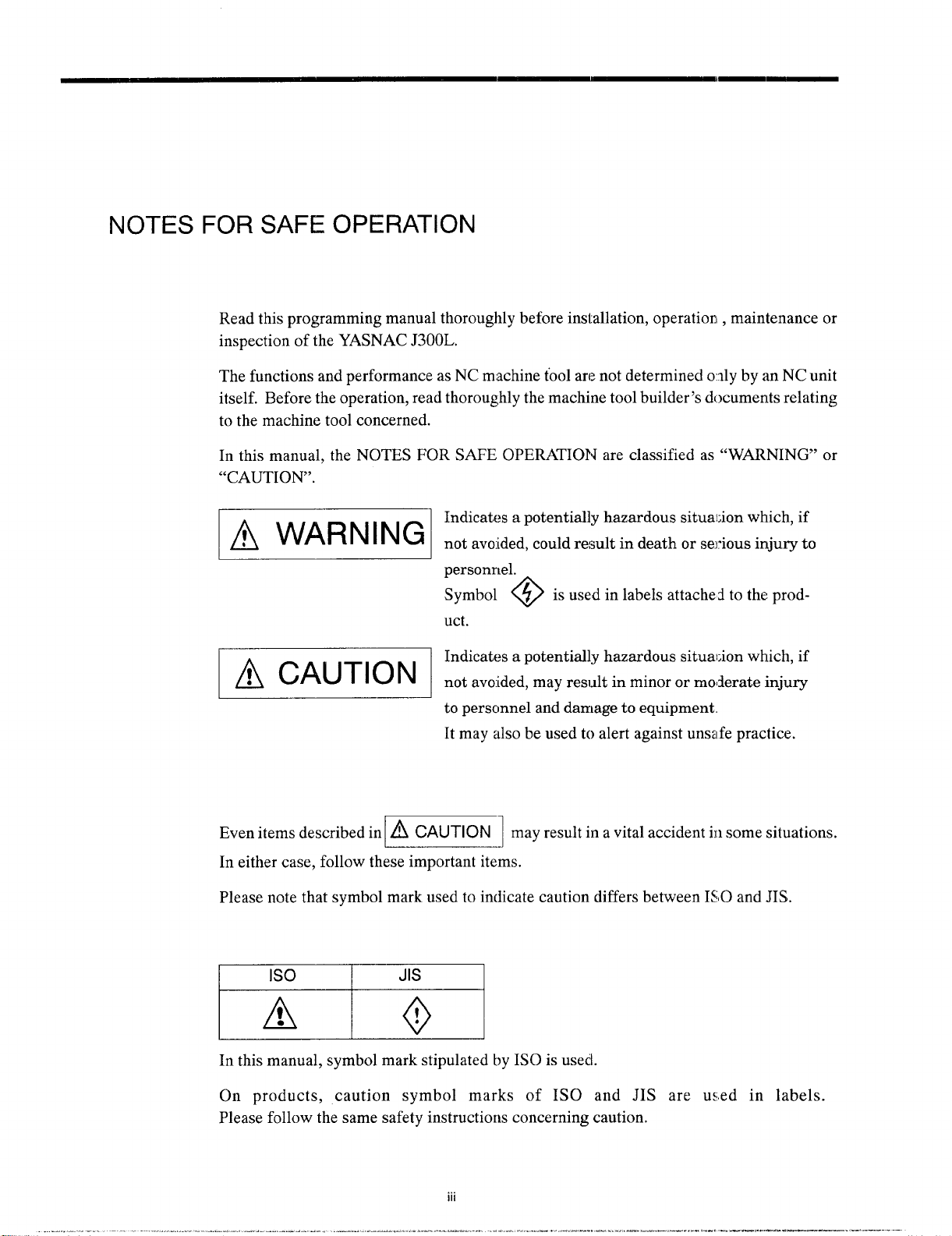
In this manual, the NOTES FOR SAFE OPERATION are classified as “WARNING”
“CAUTION’.
Indicates a potentially hazardous situa;ion which, if
~ WARNING
m!mi!l
Even items described inl ~
In either case, follow these important items.
Please note that symbol mark used to indicate caution differs between 1S0 and JIS.
not avoided, could result in death or serious injury to
personnel.
Symbol
uct.
Indicates a potentially hazardous situa;ion which, if
not avoided, may result in minor or mo,ierate injury
to perscmnel and damage to equipment.
It may also be used to alert against unsafe practice.
is used in labels attached to the prod-
@
CAUTION I may result in a vital accident insome situations.
or
In this manual, symbol mark stipulated by 1S0 is usecl.
On products, caution symbol marks of 1S0 and JIS are used in labels.
Please follow the same safety instructions concerning caution.
Ill
Page 5

KEY TO WARNING LABELS
The following warning labels are used with the YASNAC J300L.
Electric shock hazard
Do not touch the terminals while the power is
on, and for 5 minutes after switching off the
power supply!
Location of label
NC unit
— Warning label
——
.—.
iv
— .-
Page 6
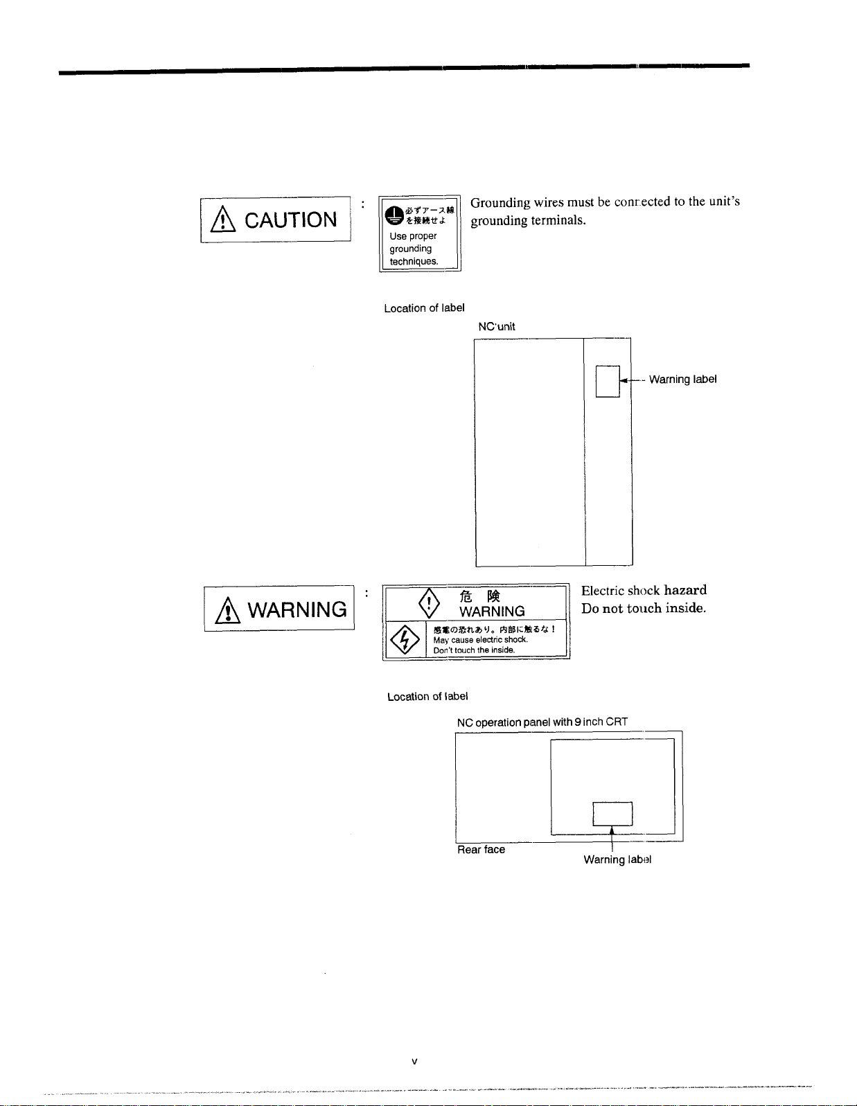
Grounding wires must be conr ected to the unit’s
grounding terminals.
Use proper
grounding
techniques.
ILJI
Location of label
I ~ WARNING I “
Location of label
NC operation panel with 9 inch CRT
~~——
Rear face
Warning Iab[?l
Page 7

CONTENTS
FOREWORD . . . . .. .. . .. .. . .. .. . . . .. . . . .. . .. . . . .. . . . .. . .. . .
NOTES FOR SAFE OPERATION . . . . . . . . . . . . . . . . . . . . . . . . . . . .
KEY TO WARNING LABELS . . . . . .. . . . .. . . . .. . .. .. . .. . . . .. . .
1. PROGRAMMING BASICS
1.1 FUNDAMENTALS OF PROGRAMMING TERMINOLOGY . ...1-2
1,141
1.1.2 Least lnputlncrement and Least Output Increment . . . . . . . . . . . . . . . . . 1-3
1.1,3 Maximum Programmable Values for Axis Movement........,.. . . . . . 1-5
1.1.4 Tape Format . . . . . . .. . . . . . . . . . . . . . . . . . . . . . . . . . . . . . . . . . . . . . . . . . . 1-6
1.1,5 Program Format . . . . . . . . . . . . . . . . . . . . . . . . . . . . . . . . . . . . . . . . . . . . . . . 1-9
1.1.6 OptionalBlockSkip(/1),(/2to/9) . . . . . . . . . . . . . . . . . . . . . . . . . . . . . . . 1-17
1.1,7 Buffer Register and Multi-active Register . . . . . . . . . . . . . . . . . . . . . . . . . 1-18
1.2 BASICS OF FEED FUNCTION . ., . . .. . . . .. . . . .. . . . . . . ...1-19
1.2.1
1.2.2 Cutting Feed (FCommand) . . . . . . . . . . . . . . . . . . . . . . . . . . . . . . . . . . . . 1-20
1.2.3 Switching between Feed per Minute Modeand Feed per
1.2.4 Automatic Acceleratio nandDeceleration . . . . . . . . . . . . . . . . . . . . . . . . . 1-27
Numerically Controlled Axesandthe Number of Simultaneously
Controllable Axes . . .. . . . . . . . . . . . . . . . . . . . . . . . . . . . . . . . . . . . . . . . . ,. 1-2
Rapid Traverse . . . . . . . . . . . . . . . . . . . . . . . . . . . . . . . . . . . . . . . . . . . . . . . 1-19
Revolution Mode (G98/G99) . . . . . . . . . . . . . . . . . . . . . . . . . . . . . . . . . . . . 1-26
iv
I
!,,
Ill
2. COMMANDS CALLING AXIS MOVEMENTS
2.1 INTERPOLATION COMMANDS ..,... . . . . . . .. .. . .. . . . . ...2-3
2.1.1
2.1.2 Linear interpolation (GOl) . . . . . . . . . . . . . . . ., . . . . . . . . . . . . . . . . . . . ...2-5
2.1.3 Circular interpolation (G02, G03, G22, G23) . . . . . . . . . . . . . . . . . . . . . . . 2-9
2.1.4 Chamfering (Gil) . . . . . . . . . . . . . . . . . . . . . . . . . . . . . . . . . . . . . . . . . . . . ,2-14
2,1.5 Rounding (G12) . . . . . . . . . . . . . . . . . . . . . . . . . . . . . . . . . . . . . . . . . . . . . ,2-16
2.1.6 Cylindrical interpolation (G124)G125) . . . . . . . . . . . . . . . . . . . . . . . . . . . 2-18
2.1.7 Polar Coordinate interpolation (G126, G127)* . . . . . . . . . . . . . . . . . . . . 2-21
2.2 USING THE THREAD CUTTING FUNCTION . . . . . . . . . . . ...2-28
2.2.1 Thread Cutingand Continuous Thread Cutting (G32) . . . . . . . . . . . . . . 2-28
2.2.2
2.2.3 Variable Lead Thread Cutting (G34)* ,, ., . . . . . . . . . . . . . . . . . . . . . ...2-37
2.3 REFERENCE POINT RETURN . . . .. . ., . . . . .. .. . .. . . . . ...2-39
2.3.1
2.3.2 Reference Point Return Check (G27) . . . . . . . . . . . . . . . . . . . . . . . . . ...2-44
2.3.3 Return from Reference Point Return (G29) . . . . . . . . . . . . . . . . . . . . . . . 2-45
2.3.4 Second to Fourth Reference Point Return (G30)* . . . . . . . . . . . . . . . . . 2-49
Positioning (GOO,G06) . . . . . . . . . . . . . . . . . ,,, ,, ...,,,.,.........,.2-3
Multiple-thread Cuttirlg(G32)* . . . . . . . . . . . . . . . . . . . . . . . . . . . . . . ...2 -34
Automatic Return to Fieference Point (G28) . . . . . . . . . . . . . . . . . . . . . . 2-39
vi
Page 8

3. MOVEMENT CONTROL COMMANDS
3.1 SETTING THE COORDINATESYSTEM . .. .. . .. . . . . . . .. ...3-3
3.1.1 Base”Coordinate System (G!jO) . . . . . . . . . . . . . . . . . . . . . . . . . . . . . . . ...3-3
3.1.2 Workpiece Coordinate System (G50T, G51) * . . . . . . . . . . . . . . . . . . . . . . 3-7
3.2 DETERMINING THE COOFIDINATE VALUE
INPUT MODES . . . . .. . . . .. . . . . . .. . . . .. . . . . . . . . .. . . . ...3-16
3.2.1
3.2.2 Diametric and Radial Commands for X-=is . . . . . . . . . . . . . . . . . . . . . . 3-19
3.2.3 Inch/Metric Input Designation (G20, G21) . . . . . . . . . . . . . . . . . . . . . . . . 3-20
Absolute/lncremental Desigrlation . . . . . . . . . . . . . . . . . .1 . . . . . . . . . ...3-16
3.3 TIME-CONTROLLING COMMANDS . . . . . .. . . . .. . . ~~. .. ...3-22
3.3.1
Dwell (G04) . . . . . . . . . . . . . . . . . . . . . . . . . . . . . . . . . . . . . . . . . . . . . . . ...3-22
3.4 TOOL OFFSET FUNCTIONS . . .. . . . . . . . . . . . . . .. . . ... ...3-23
3.4.1
3.4.2 Tool Position Offset . . . . . . . . . . . . . . . . . . . . . . . . . . . . . . . . . . . . . . . . ...3-24
3.4.3 Nose ROffset Function (G4(l, G41/G42) . . . . . . . . . . . . . . . . . . . . . . . . . 3-29
Tool Offset Data Memory . . . . . . . . . . . . . . . . . . . . . . . . . . . . . . . . . . . . .. 3-23
3.5 SPINDLE FUNCTION (S FIJNCTION) . . . . . . . . . . . . . ... ...3-75
3.5.1
3.5.2 Maximum Spindle Speed Command (G50S) . . . . . . . . . . . . . . . . . . . . . 3-76
3.5.3 Constant Surface Speed Control (G96, G97)* . . . . . . . . . . . . . . . . . . . . 3-77
3.5.4 Rotary Tool Spindle Selection Function . . . . . . . . . . . . . . . . . . . . . . . . . . 3-81
Spindle Command (S5-digit Command) . . . . . . . . . . . . . . . . . . . . . . . . . . 3-75
3.6 TOOL FUNCTION (T FUNCTION) . . . . . . . . . . . . . . . . . . . ...3-82
3.6.1
3.6.2 T6-digit Command . . . . . . . . . . . . . . . . . . . . . . . . . . . . . . . . . . . . . . . . . ...3-82
T4-digit Command . . . . . . . . . . . . . . . . . . . . . . . . . . . . . . . . . . . . . . . . . ...3-82
3.7 MISCELLANEOUS FUNCTION (M FUNCTION) . . . . c. . . ...3-83
3.7.1
3.7.2 internally Processed M Codes . . . . . . . . . . . . . . . . . . . . . . . . . . . . . . . ...3- 84
3.7.3 General Purpose M Codes . . . . . . . . . . . . . . . . . . . . . . . . . . . . . . . . . . ...3-85
. .—.——-—- ..— ..—.-—-----
MCodes Relating to Stop Operation (MOO, MOl, M02, M30) . . . . . . . . 3-83
vii
——— .- .._—-.—...—..-. -—-.-.... ..—— ..-.. - .—, -—-.. —.-..-,— . .. —.-—.——
Page 9

4. ENHANCED LEVEL (COMMANDS
4.1 PROGRAM SUPPORT FUNCTIONS(l) ,.. .: .,............4-3
4.1.1
4.1.2 Multiple Repetitive Cycles (G70to G76)* . . . . . . . . . . . . . . . . . . . . . . . . 4-16
4.1.3 Multiple Chamfering/Rounding on Both Ends of Taper (Gill) * . . . . . . 4-56
4.1.4 Multiple Chamfering/Rounding on Arc Ends (G112) *. , . . . . . . . . . . . . . 4-70
4.1.5
4.2 PROGRAM SUPPORT FUNCTIONS
4.2.1
4.2.2 Programmable Data lnput(GIO) *.... . . . . . . . . . . . . . . . . . . . . . . . ...4-104
4.2.3 Subprogram Call Up Function (M98, M99) . . . . . . . . . . . . . . . . . . . . . . . 4-106
4.2.4 Stored Stroke Limit B(G36to G39) . . . . . . . . . . . . . . . . . . . . . . . . . ...4-108
Canned Cycles (G9Cl. G92. G94) . . . . . . . . . . . . . . . . . . . . . . . . . . . . . . . . . 4-3
Hole-machining Canned Cycles
(G80to G89, G831, G841, G861) . . . . . . . . . . . . . . . . . . . . . . . . . . . . ...4-79
(2) , . . . . . . . . . . . . . . ...4-94
Solid Tap Function (G84, G841) *..... . . . . . . . . . . . . . . . . . . . . . . . . ..4-g4
4.3 AUTOMATING SUPPORT FUNCTIONS . . . . .. . . . . . . . . . . .4- 114
4,3.1
4.3.2 Tool Life Control Function (G122, G123) . . . . . . . . . . . . . . . . . . . . . . . . 4-117
4,4 MICROPROGRAMS . . .. .. . . . .. . .. . . . .. . .. .. . .. . . . .. . 4-126
4.4.1
4.4.2
4.4.3 Variables, . . . . . . . . . . . . . . . . . . . . . . . . . . . . . . . . . . . . . . . . . . . . . . . ...4 -138
4.4.4 Operation instructions . . . . . . . . . . . . . . . . . . . . . . . . . . . . . . . . . . . . . ...4-162
4.4.5 Control instructions .,, ,,, . . . . . . . . . . . . . . . . . . . . . . . . . . . . . . . . . ...4-164
4,4,6 Registering the Microprogram . . . . . . . . . . . . . . . . . . . . . . . . . . . . . . ...4 -170
4.4.7 RS-232C Data Output 2( BPRNT, DPRNT) . . . . . . . . . . . . . . . . . . . . . . 4-171
4.4.8 Microprogram Alarm Numbers,,,. , . . . . . . . . . . . . . . . . . . . . . . . . ...4-176
4.4.9 Examples of Microprograms, ,., ,, ., . . . . . . . . . . . . . . . . . . . . . . . ...4-177
Skip Function (G31) *.....,,.,...,.. . . . . . . . . . . . . . . . . . . . . . . ...4-114
Differences from Subprograms . . . . . . . . . . . . . . . . . . . . . . . . . . . . . . . . 4-126
Microprogram Call (G65, G66, G67)*. . . . . . . . . . . . . . . . . . . . . . . ...4-128
APPENDIX 1 G CODE TABLE
APPENDIX l.l GCODE TABLE . . . . . . . . . . . . . . . . . . . . . . . . . . . . . Al-2
APPENDIX 2 INDEX
..
Vlll
Page 10

PROGRAMMING BASICS
Chapter 1 describes the basic terms used in programming
and
the feed functions.
1.1
FUNDAMEN”rALS OF PROGRAMMING
TERMINOLOGY. . . . . . . . . . . . . . . . . . . . .1-2
1.1,1
Numerically Controlled Axes and the Nulmber
of Simultaneously Controllable Axes . . . . . . . . 1 -2
1.1,2
1.1.3
1,1.4
1,1.5
1.1.6 Optional Block Skip (/1), (/2 to /9) * . . . . . . . . 1-17
1.1.7
1.2
BASICS OF I=EED FUNCTION . . . . . i .. 1-19
1.2.1
1.2.2 Cutting Feed (F Command) . . . . . . . . . . . . . . 1-20
1.2.3
1.2.4
Least Input Increment and Least Output
Increment . . . . . . . . . . . . . . . . . . . . . . . . . . . . . . ‘1-3
Maximum Programmable Values for Axis
Movemen t . . . . . . . . . . . . . . . . . . . . . . . . . . . . . 1-5
Tape Format . . . . . . . . . . . . . . . . . . . . . . . . . . . . 1-6
Program Format . . . . . . . . . . . . . . . . . . . . . . . . . 1-9
Buffer Register and Multi-active Registel’ . . . 1-18
Rapid Traverse . . . . . . . . . . . . . . . . . . . . . . . . . 1-19
Switching between Feed per Minute Mode
and Feed per Revolution Mode (G98/G$19) . 1-26
Automatic Acceleration and Deceleration . . . 1-27
Page 11
1.1
FUNDAMENTALS OF PROGRAMMING TERMINOLOGY
This section describes the basic terms used in programming.
1.1.1
Numerically Controlled Axes and the Number of Simultaneously Controllable
Axes
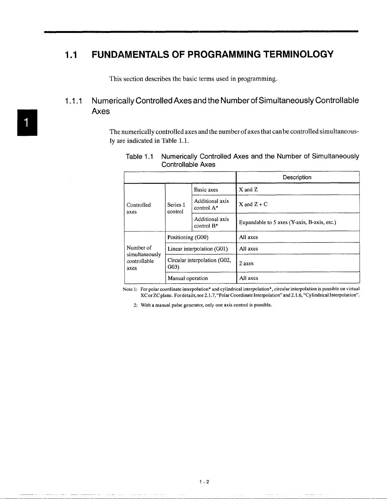
The numerically controlled axes and the number of axes that can be controlled simultaneously are indicated in Table 1.1.
—.. . . . . .,-. .. . . ... . ,, , -. ,.
[able 1.1 Numerically Uontroilea Axes ana tne NumDer oT Slmul[aneously
Controllable Axes
I
Description
IBasic axes lXand Z
Controlled
axes
Number of
simttltaneousl y
controllable
axes
Note 1: For polar coordinate interpolation* and cylindrical interpolation
XCor ZCplane. For details, see 2.1.7,’’Polar Coordinate Interpolation” and 2.1.6, “Cylindrical Interpolation”.
2: With a manual pulse generator, only one axis control is possible.
Series 1
control
Positioning (GOO) All axes
Linear interpolation ((301)
Circular interpolation (G02,
G03)
Manual operation
Aclditional axis
control A*
Additional axis
control B*
}
Xand Z+C
Expandable to 5 axes (Y-axis, B-axis, etc.)
AUaxes
2 axes
All axes
*, circular interpolation is possible on virtual
,
I
I
—
1-2
..—.- —
Page 12

1.1 FUNDAMENTALS OF PROGRAMMING TERMINOLOGY
1.1.2 Least Input Increment and Least Output Increment
The least input and output increments vary depending cmthe type of controlled axis whether
it is a rotary axis or a linear axis.
(1)
LeastInput Incrementand10-tilmeInputIncrement
The least input increment to express axis movement distance that is input by using
punched tape or manual data input switches is indicated in Table 1,2.
Table 1.2 Least Input Increment (pml 000 DO=O)
@
!
i
2
i
?
q
O
Metric Input
Inch Input
By setting “l” for parameter pm1000 DO (pm1000 DO = 1), the “lO-time input increment” specifications indicated in Table 1.3 is selected.
Table 1.3 10-time Input Increment (pml 000 DO= 1)
Metric Input
Inch Input
Note: Selection of “mm-input” and “inch-input” is made by the setting parameter pmOO07[IOorbythespecification
ofG20/G21
Disregarding of the least input increment mode which has been select ed, tool.offset data
are always written in units of 0.001 mm (or 0.0001 inch, or 0.001 deg.). Offset movement is possible in the specified
the following operations and the commands for them must be given in units c}f0.01 mm.
●
Data writing in the MDI mode
‘X-’:zzz:::: :3
‘X-’::z ~:G:-”-3
vake. If the offset data are set in units of 0.01 mm,
●
Programming for the memory mode operation
●
Program editing
Page 13
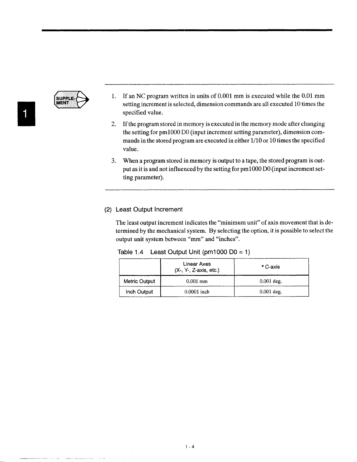
1. If an NC program written in units of 0.001 mm is executed while the 0.01 mm
setting increment is selected, dimension commands are.all executed 10 times the
specified value.
2. If the program stored in memory is executed in the memory mode after changing
the setting for pm1000 DO (input increment setting parameter), dimension commands in the stored program are executed in either 1/10 or 10 times the specified
value.
3. When a program stored in memory is output to a tape, the stored program is output as it is and not influenced by the setting for pm1000 DO (input increment setting parameter).
Least Output Increment
(2)
The least output increment indicates the “minimum unit” of axis movement that is determined by the mechanical system. By selecting the option, it is possible to select the
output unit system between “mm” and “inches”.
Table 1.4 Least Output Unit (pml 000 DO = 1)
Linear Axes
(X-, ‘f-, Z-axis, etc.)
Metric Output 0.001 mm 0.001 deg.
Inch Output
E
0.0001inch
* C-axis
0.001 deg.
..—.— ———
“l-4
Page 14

1.1 FUNDAMEN”rALS OF PROGRAMMING TERMINOLOGY
1.1.3 Maximum Programmable Values for Axis Movement
The maximum programmable values that can be designated for a move command are indicated in Table 1.5. The maximum programmable values indicated in these tables are applica-
ble to addresses I, J, K, R, A, and B which are used for designating “distance” in addition
to the move command addresses X, Y, Z, C, U, W, V, and H.
u
Table 1.5 Maximum Programmable Values for Axis Movement
Linear Axes
(X-, Y-, Z-axis, etc.)
Metric Output
Metric Input
Inch Input
Metric Input
Inch Output
Inch Input
+ 999999.999mm + 999999.999 deg.
+ 39370.0787inch t 999999.999 deg.
A999999.999 mm
+ 99999.9999 inch
—,
* C-axis
,—
—.
k
!199999.999deg.
k S199999.999deg.
=
In incremental programming, the values 10be designated must not exceed he maximum programmable values indicated above. In absolute programming, the mmw distance of each
axis must not exceed the maximum programmable values indicated abclve. In addition to
the notes indicated above, it must also be taken into consideration that the cumulative values
of move command must not exceed the values indicted in Table 1.6.
Table 1.6 Maximum Cumulative Values
\ Metric Input ] + 999999.999mm
I Inch Input I + 999999.9999inch
Note: The values indicated above do not depend on the “least output increment”.
I A 999999.999 deg. I
*
I
999999.999deg.
I
1-5
Page 15

1.1.4 Tape Format
The following describes the important items concerning the tape format.
(1) Label and Label Skip
By entering “label” at the beginning of a punched tape, classification and handling of
tape can be facilitated.
The label skip function disregards the data appearing before the first EOB code. With
this feature, label can contain address characters and function codes which are not supported by the NC. A code that does not match the selected parity scheme can also be
used. The label skip function becomes enabled when the power is turned ON or when
the NC is reset. While the li~belskip function is enabled, “LX” message is displayed
on the screen.
Tape Start and Tape End
(2)
At the start and end of a tape, the same code (see Table 1.7) should be punched.
Table 1.7 Tape Start and Tape End
Description
F’:
● The ER code (rewind stop code) entered following the tape start label indicates
the rewind stop when the tape is rewound by the tape rewind command.
● The ER code, expressing the tape end, indicates the stop point when several
part programs are stored in NC memory.
Tape startflape end
.—
1-6
Page 16

1.1 FUNDAMENTALS OF PROGRAMMING TERMINOLOGY
l——
- Label
~=~
ER CR
‘— Program part
T T
/
Tape start
(Called as ‘(%” or “Rewind Stop” code)
Note:
As theendof program code, M02
are
used as the p;ogram end Mcode is determined according to the setting forparamt.terpm3005 D3.
Fig.1.1
Program start
(Called as “EOW or “End of Block’’. code)
SingleMainProgramPunchedonTape(EIACocle)
‘~—
(
Comment y ,–
part
+i
orM99canbeusedinsteadof’M30.Whetherornotthe Wcodesindicatedabove
~—
1~1
Tape end
LF/NL
0/0
—=— Program part
=I=Q=
- “beITrlTI T
Tape start
Program part _
Fig. 1,2
Program start
M3O&-
Program —
end
r
-p
Program part
Multiple Programs F’unched on Tape (EIA Code)
Tape end —-
r
\
Tape end
1-7
Page 17

(3) Program Start and Program End
(a) Program start
When punching a program on a tape, the following code should be punched to declare the beginning of a program. This code cancels the label skip function.
Table 1.8 Program St:irt
Description
E=.
(b)
Program end
Program start
Any of the following codes indicated in Table 1.9 should be punched at the end of
a program to declare the program end.
Table 1.9 Program End
EIA 1s0 Description
M02CR
M30CR
M99CR M99LFJNL Subprogram end
B
Note 1:
When “M02CR” or “M30LF,’NL” is executed, the equipment may or may not be reset or rewound depending
on equipment specifications.
Refer to the manual published by the machine tool builder.
2:
When multiple part programs are started in the NC memory, control may move to the next part program after
reading the program end code shown above.
Thisoccurs when part programs are entered by total input.
3:
If ER or LF/NLcode is executed for a program in which neither M02 nor M30 is entered at the end of the program; the NC is reset.
Mo2LF/NL
M30LFINL Program end and rewind
Program end
. — —-
“I-8
Page 18
1.1.5 Program Format
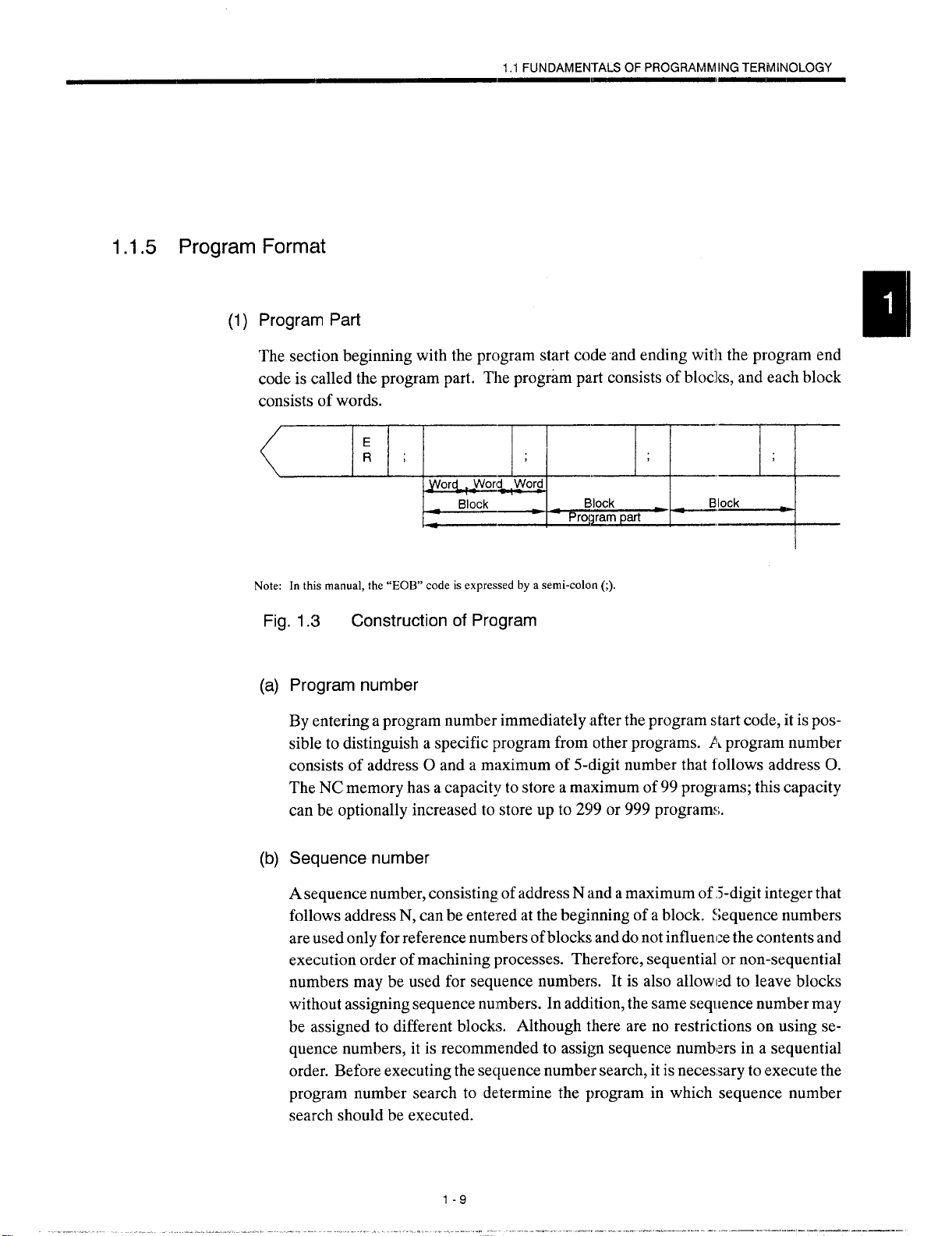
(1) Program Part
The section beginning with the prc)gram start code-and ending with the program end
code is called the program part. The program part consists of blocks, and each block
consists of words.
E
R ;
1.1 FUNDAMENTALS OF PROGRAMMING TERMINOLOGY
l——
I
Block
Note: In this manual, the “EOB” code is expressed by a semi-colon C).
- -
Block Block
Program part
- = z
,—
Fig. 1.3 Construction of Program
Program number
(a)
By entering a program number immediately after the program start cocle, it is possible to distinguish a specific program from other programs. A program number
consists of address O and a mi~ximum of 5-digit number that follows address O.
The NC memory has a capacity to store a maximum of 99 prog]ams; this capacit y
can be optionally increased to store up to 299 or 999 programx.
(b)
Sequence number
A sequence number, consisting, of address N and a maximum of 5-digit integer that
follows address N, can be ente:red at the beginning of a block. Sequence numbers
are used only for reference numbers of blocks and do not influence the contents and
execution order of machining processes. Therefore, sequential or non-sequential
numbers may be used for sequence numbers,
It is also allowed to leave blocks
without assigning sequence nu:mbers. In addition, the same sequence number may
be assigned to different blocks. Although there are no restrictions on using se-
quence numbers, it is recommended to assign sequence numblars in a sequential
order. Before executing the sequence number search, it is necessary to execute the
program number search to determine the program in which sequence number
search should be executed.
Page 19
——..
——-
———
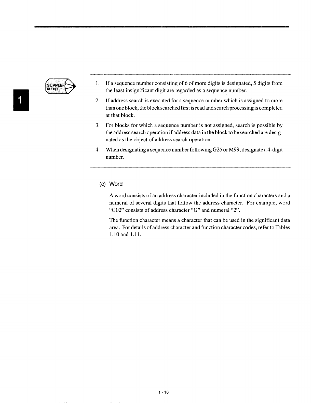
1. If a sequence number consisting of 6 of more digits is designated, 5 digits from
the least insignificant digit are regarded as a sequence number.
2. If address search is executed for a sequence number which is assigned to more
than one block, the block searched first is read and search processing is completed
at that block.
3. For blocks for which a sequence number is not assigned, search is possible by
the address search operation if address data in the block to be searched are designated as the object of address search operation.
4. When designating a sequence number following G25 or M99, designate a 4-digit
number.
(c) Word
A word consists of an address character included in the function characters and a
numeral of several digits that follow the address character. For example, word
“G02” consists of address character “G’ and numeral “2”.
The function character means a character that can be used in the significant data
area. For details of address character and function character codes, refer to Tables
1.10 and 1.11.
1-1o
Page 20
1.1 FUNDAMENTALS OF PROGRAMM ING TERMINOLOGY
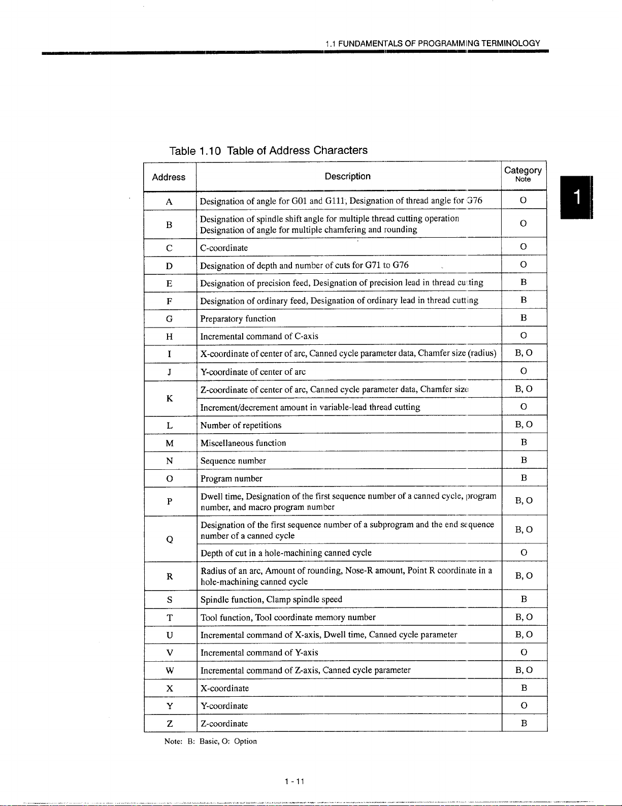
Table 1.10 Table of Address Characters
1——
Address
I
A
B
c
D
E
F
G
H
I
J
‘t----- ‘–
L
M IMiscellaneous function
Designation of angle for GO1 and Gill, Designation of thread angle for S76
Designation of spindle shift angle for multiple thread cutting operation
Designation of angle for multiple chamfering and rounding
IC-coordinate
Designation of depth and number of cuts for G71 to G76 .
Designation of precision feed, Designation of precision lead in thread cu.ting
Designation of ordinary feed, Designation of ordinary lead in thread cutting
Preparatory function
Incremental command of C-axis
X-coordinate of center of arc, Canned cycle parameter data, Chamfer size (radius) B, O
Y-coordinate of center of arc
Z-coordinate of center of arc, Canned cycle parameter data, Chamfer sizti
Increment/decrement amount in variable-lead thread cutting
INumber of repetitions
Description
——
—.
%
o
o
H
Iol
o
B
B
B
o
o
B, O
o
t----i
I B,O I
IBI
Dwell time, Designation of the first sequence number of a canned cycle, Iprogram ~ o
-
Q
R
s
T
u
v
w
X IX-coordinate IBI
Y
z
Note: B: Basic. O: O~tion
number, and macro program number
Designation of tbe first sequence number of a subprogram and the end sequence B o
number of a canned cycle
Depth of cut in a hole-machining canned cycle
Radius of an arc, Amount of rounding, Nose-R amount, Point R coordinate in a B o
hole-machining canned cycle
Spindle function, Clamp spindle speed
Tool function, Tool coordinate memory number
Incremental command of X-axis, Dwell time, Canned cycle parameter B, O
Incremental command of Y-axis o
Incremental command of Z-axis, lCannedcycle parameter
IY-coordinate
IZ-coordinate
1-11
—,
—
—.
‘H
o
u
1-.-d
B
B, O
.+
I B,O I
IBI
.-...—.—
Page 21
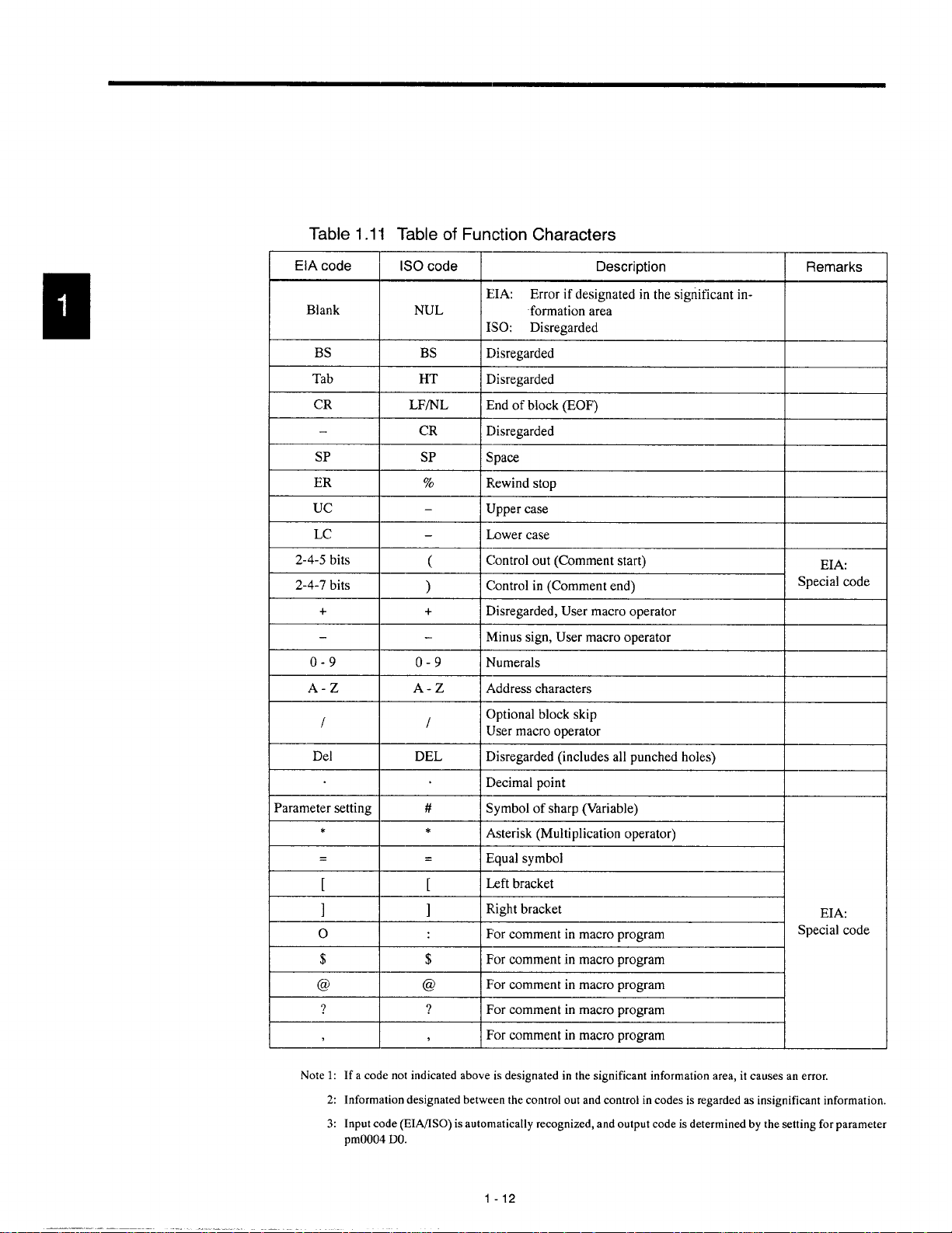
Table 1.11 Table of Function Characters
EIA code ISO code Description
EIA: Error if designated in the significant in-
Blank NUL
formation area
ISO: Disregarded
BS BS Disregarded
Tab
HT
Disregarded
CR LF/NL End of block (EOF)
CR Disregarded
SP SP Space
ER
Uc
LC
2-4-5 bits
2-4-7 bits
+
—
%
—
—
(
)
+
Rewind stop
tJpper case
Lower case
Control out (Comment start)
Qrrrtrol in (Comment end)
Disregarded, User macro operator
Minus sign, User macro operator
o-9 0-9 Numerals
A-Z
I
Del
A-Z
/
Address characters
C)ptionalblock skip
tJser macro operator
DEL Disregarded (includes all punched holes)
Decimal point
Parameter setting # Symbol of sharp (Variable)
*
.
[
1
o
$ $
@ @
? ‘/
*
=
[
1
Asterisk (Multiplication operator)
Equal symbol
L,eftbracket
Right bracket
For comment in macro program
For comment in macro program
For comment in macro program
For comment in macro program
,
For comment in macro program
Remarks
EIA:
Special code
EIA:
Special code
Note
1: If a codenot indicatedaboveis designatedinthesignificantinformationarea,it causesanerror.
2: Informationdesignatedbetweenthecontroloutandcontrolincodesis regardedasinsignificantinformation.
3: Input code (EIA/fSO) is automatically recognized, and output code is determined by the setting for parameter
pmOO04
DO.
1-12
Page 22

1.1 FUNDAMENTALS OF PROGRAMMI NG TERMINOLOGY
(d) Block
● A block consists of words to define a single step of operatio]l. One block ends
with the EOB (end of block) code. The EOB code is expressed by “CR’ in
the EIA code system and “;LF/NL” in the 1S0 code system.
In this manual, it is expressed by a semicolon “;”
ple.
● Characters not indicated in Tables 1.10 “Table of Addrew Characters” and
1.11 “Table of Function Characters” must not be used.
● One block can contain up to 128 characters. Note that inval id chamcters such
as “Del” are not counted.
to make the explanation sim-
.—
~=,,e,) +--A
(a) Adding a character for TV check (an error occurs if an even number of characters is coI Itained in a block.)
; NO058G03X .-. Z . . .
3 E“””” F’”; ,___!
L—____— ‘essth”’129 –
Fig. 1,4 Block
(2) Comment Part
A comment can be displayed by using the contrcd out and control in
(a) Entering a comment in a program
It is possible to display a required comment on the screen by enclosing it with the
control out and control in codes in a part program. The information enclosed by
these codes is regarded as insignificant information.
characters in a block
(b) Number of valid characters atlowed in a block
A
codes.
Page 23

(b) Entering the control out and control in codes
The control out and control in codes can be entered in.the same manner as entering
ordinary characters.
● “(’’:Press the [U] key after pressing the [SHIFT] key.
● “)’’:Press the [V] key after pressing the [SHIFT] key.
(Operation panel with 9-inch CRT)
,GQ
o
o—
0
I
Note 1: The characters that can be entered between the control out and control in codes are those that are entered by
2: It is not allowed to use tbe control out and control in codes in the area which are already enclosed by the control
Fig. 1.5 Characters that can be Entered between Control Out and Control
+&
using the keys enclosed by dark line in Fig. 1.5.
out and control in codes.
In Codes (Keys Enclosed by Dark Line)
-“
Charactersthat
“(” (control out) and “)” (control in) codes
can be entered between
I
1-14
Page 24
1.1 FUNDAMEN1-ALS OF PROGRAMMIIQG TERMINOLOGY
1—
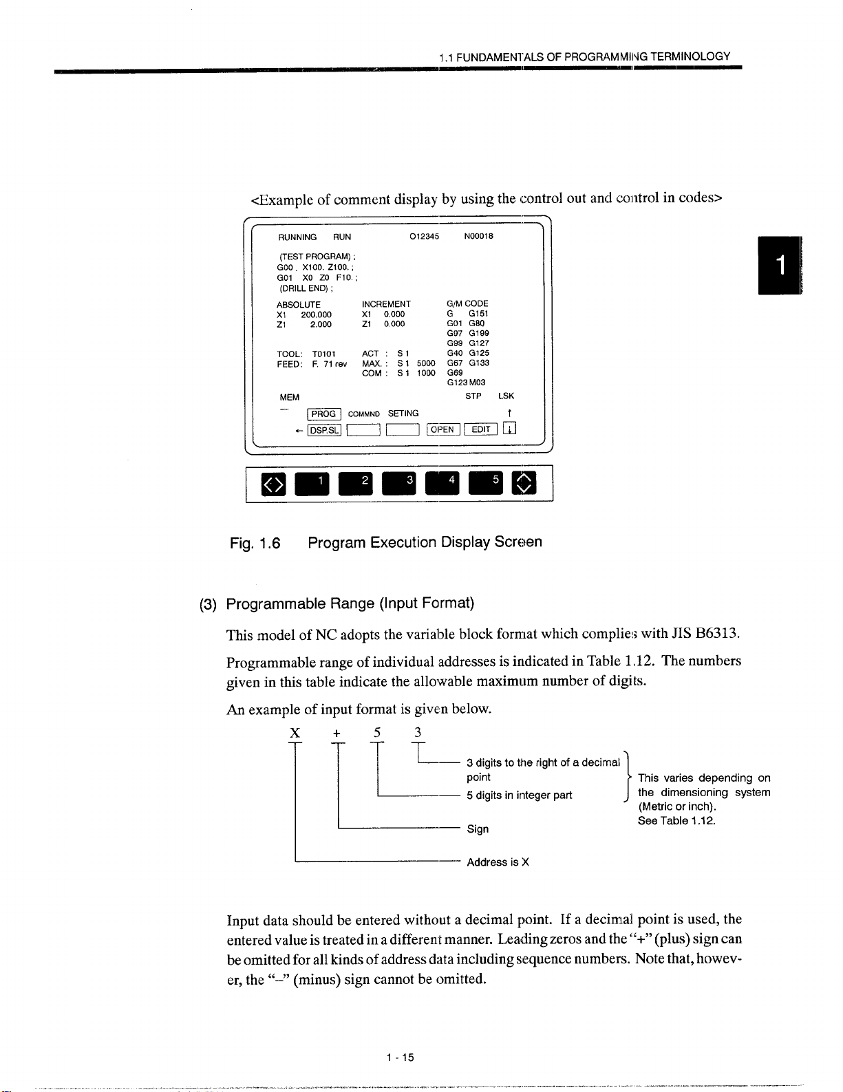
<Example of comment display by using the control out and co lntrol in codes>
RUNNING RUN
(TESTPROGRAM);
GOO X1OO.Z1OO.;
Go1 XO ZO F1O.;
(DRILLEND);
ABSOLUTE
xl 200.000
Z1 2.000
TOOL: TOIO1 ACT : S1
FEED: F. 71rev
MEM
INCREMENT
xl 0.000
Z1 0000
MAX : S1 5000 G67 G133
COM: S1 10MI G69
- p] co. . . . SETING
“EEJmn@zElL2iA
.
Emilmmniiiiiil
Fig. 1.6
Programmable Range (Input Format)
(3)
Program Execution Display Screen
012345
NooO18
G/MCODE
G151
G
Go1 G80
G97 G199
G99 G127
G40 G125
G123M03
STP
LSK
This model of NC adopts the variable block format which complies with .lIS B6313.
Programmable range of individual addresses is indicated in Table 1.12. The numbers
given in this table indicate the allowable maximum number of digits.
An example of input format is given below.
x+53
3 digits to the right of a decimal
point
5 digits in integer part
Sign
Address is X
This varies depending on
the dimensioning system
1
(Metric or inch).
See Table 1.12.
Input data should be entered without a decimal point. If a decimall point is used, the
entered value is treated in a different manner. Leading zeros and the’ ‘+” (plus) sign can
be omitted for all kinds of address data including sequence numbers. Note that, howev-
er, the “-” (minus) sign cannot be omitted.
Page 25
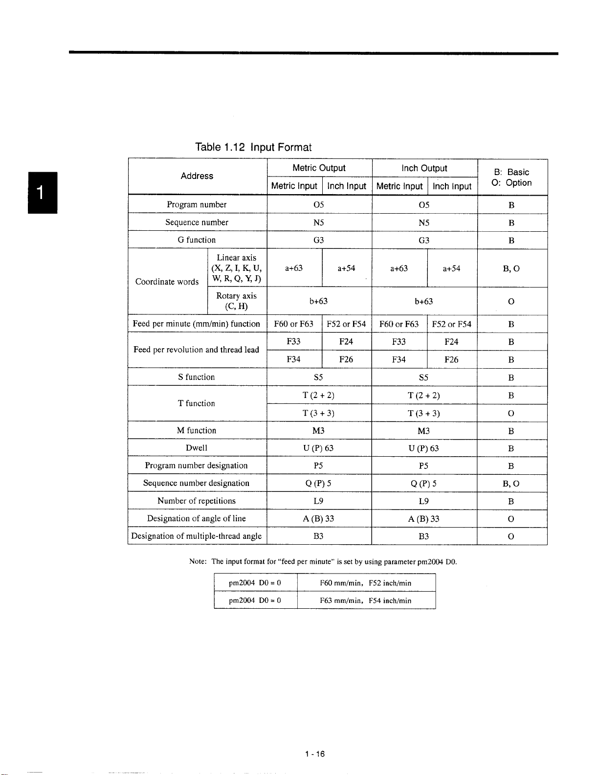
Table 1.12 Input Formal
Address
Program number
Sequence number
G function
Linear axis
(x z, L K u,
Coordinate words
Feed per minute (mm/min) function
Feed per revolution and thread lead
S function
T function
M function
W, R, Q,~J)
Rotary axis
(c, H)
Dwell
Metric Output Inch Output
MetricInput Inch Input MetricInput Inch Input
05 05
N5
G3 G3
a+63
F60 or F63
F33
F34
T(2+2) T(2+2)
T(3+3) T(3+3)
U (P) 63 U (P) 63
a+54 a+63 a+54 B, O
b+63 b+63 o
F52 or F54 F60 or F63 F52 or F54
F24 F33 F24
F26 F34 F26
S5 S5
M3 M3
N5 B
B: Basic
O: Option
B
B
B
B
B
B
B
o
B
B
Program number designation
Sequence number designation
Number of repetitions
Designation of angle of line
Designation of multiple-thread angle
Note: The input format for “feed per minute” is set by using parameter pm2004 DO,
P5 P5
c! (P) 5
L9 L9
A (B) 33 A (B) 33
B3 B3
Q(P)5
B
B, O
B
0
o
1-16
Page 26

1.1,6 Optional Blclck Skip (/1), (/2 to /9) *
If a block containing the slash code “/n (n=l to 9)” is executed with the external optional
block skip switch corresponding to the designated number set ON, the commands in the
block following the slash code to the end of block code are disregarded. The slash code “/n”
can be designated at any position in a block.
Example:
/ 2 N 1234 GOOX1OO / 3 Z200;
If the “/2” switch is ON, the entire block is disregarded, and
if “/3” switch is ON, this block indicates the following.
1.1 FUNDAMENTALS OF PROGRAMMING TERMINOLOGY
SUPPLE-
MENT
(3
N 1234
“l” can be omitted for “/1”.
1.
2. The optional block skip function is processed when a part program is read to the
buffer register from either the tape or memory. If the switch is set ON after the
block containing the optional block skip code is read, the block is not skipped.
3. ~le optional block skip function is disregarded for program reacling (input) and
punch out (output) operation.
GOOX1OO;
. .-. .—.....-. .—
1-17
— ....-. -—.--.. --.. —”---------
~—... ,-. —
_.-. —- ——. — ——. —
Page 27
1.1.7 Buffer Register and Multi-active Register
By using the buffer register and multi-active register, the NC ensures smooth control of the
machine by reading the blocks of data into the buffer register.
(1)
Buffer Register
In normal operation, two blocks of data are buffered to calculate the offset and other
data that are necessary for the succeeding operation.
In the nose R offset mode (option), two blocks of data (a maximum of four blocks of
data, if necessary) are buffered to calculate the offset data that are necessary for the
succeeding operation. In both of the normal operation mode and nose R offset mode,
the data capacity of one block is amaximum of 128 characters, including the EOB code.
(2)
Multi-active Registers *
With a part program enclosed by M93 and M92, a maximum of seven blocks of data
are buffered. If the time required for automatic operation of these seven buffered blocks
is longer than the time required for the buffering and calculation of the offset data for
the next seven blocks, the program can be executed continuously without a stop between blocks.
Table 1,13 M92 and M9:3 Codes
m
M92 Multi-active registers OFF
Function
Multi-activeregistersON
A
Page 28

1.2 BASICS OF FEED FUNCTION
This section describes the feed function that specifies feedrate (distance per minute, distance
per revolution) of a cutting tool.
1.2.1 Rapid Traverse
1.2 BASICS CIF FEED FUNCTION
SUPPLEMENT
(ID
Rapid traverse is used for positioning (GOO)and manual rapid traverse (RAPID) operation.
In the rapid traverse mode, each axis moves at the rapid traverse rate set for the individual
axes; the rapid traverse rate is determined. by the machine tool builder and :Setfor the individual axes by using parameters. Since the. axes move independently of each other, the axes
reach the target point at different time. Therefore, the resultant tool paths are not a straight
line generally.
The rapic, traverse override function can adjust the set rapid traverse rate to Fo, 25%, 50%,
and 100%~where F. indicates a fixed feedrate set for parameter pm244’7.
1. Rapid traverse rate is set in the following units for the individual axes.
Setting units of rapid traverse rate
2. The upper limit of the rapid traverse rate is 240,000 mm/min. Since the most appropriate value is set conforming to the machine capability, refer to the manuals
published by the machine tool builder for the rapid traverse rate of your machine.
0.001 mm/min
or
1 deg.lmin
m
Page 29

1.2.2 Cutting Feed (F Command)
The feedrate at which a cutting tc)olshould be moved in the linear interpolation (GO1) mode
or circular interpolation (G02, G03) mode is designated using address characters F and E.
The axis feed mode to be used is selected by designating the feed function G code (G98 or
G99) as indicated in Table 1.14. Select the required feed mode by designating the feed func-
tion G code before specifying an F and E code.
Table 1,14 Cutting Feecl Mode G Codes
m~
G98
\ G99 IDesignation of feed per revolution (mm/rev) mode \ 10 I
Designation of feed per minute (mm/min) mode
! 1
Function
Group
10
See 1.2.3 “Switching between Feed per Minute Mode and Feed per Revolution Mode” for
details of these G codes. F and IEcodes are modal and once designated they remain valid
until another For E code is designated. If feed mode designation G codes are switched between G98 and G99, however, it is necessary to designate the F and E code again. If no new
F and E codes are designated, alarm “0370” occurs. Note that it is not allowed to designate
an E code in the G98 (feed per minute) mode. If an E code is designated in the G98 mode,
alarm “0371” occurs.
————
.- ..— —. .— -—
1-20
Page 30

1.2 BASICS OF FEED FUNCTION
(1) Feed per Revolution Mode (G99)
A feedrate of a cutting tool per revolution of the spindle (mm/rev, inch/rev) can be designated by a numeral specified following address character F or E.
Table 1.15 Programmable Range of F and E Commands
(Feed
perRevolutionMode)
Format
F33
mm input
mm output
inch input
mm input
inch output
inch input
I -
Note:!: Theallowablemaximumvalueforthe X-axisis1/2ofthe value indicatedin theta ble.
;!: The upper ]jmjt of feedrates could be re~tr-jcted
programmable feedrate range, refer to the manuals published by the machine tool builder.
The feedrate per revolution is further restricted as indicated in Table 1.16 due to spindle
speed S.
Table 1.16 Restrictions on F and E Commands by Spindle Speed
E34
F24
E26
F33
E34
F24
E26
FO.001.to F500.000 mm/rev
EO.0001 to E500.0000 mm/rtv
FO.0001 to F19.6850 inch/re’~
EO.000001 to E19.685000 inch/rev
FO.001 to F1270.000 mm/re~
EO.0001 to E1270.0000 mm/rev
FO.0001 to F50.0000 inch/re+~
EO.000001 to E50.00000 inch/rev
bytheservosystemand[hemechanical system. For the actual
Programmable
Range
Page 31
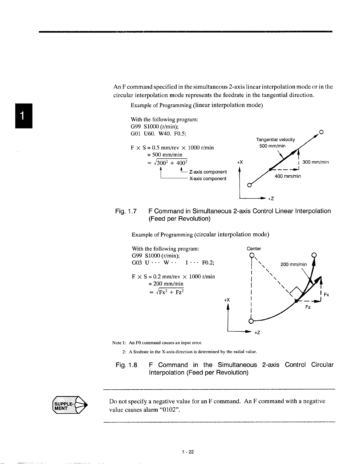
An F command specified in the simultaneous 2-axis linear interpolation mode or in the
circular interpolation mode represents the feedrate in the tangential direction.
Example of Programming (linear interpolation mode)
Whh the following program:
G99 S1OOO(r/rein);
GO1 U60. W40. FO.5;
F x S = 0.5 mm/rev x 1000 r/rein
= 500
mm/min
= ~~
~-
Z-axis component
- X-axis component
Tangential velocity
mm/min
500
+x I 300
——
4
400 mm/min
o
mm/min
L~
+Z
Fig. 1.7 F Command in Simultaneous 2-axis Control Linear Interpolation
(Feed per Revolution)
Example of Programming (circular interpolation mode)
With the following program:
G99 S1OOO(r/rein);
G03U. ”” W”.
F x S = 0.2 mm/rev x 1000 r/rein
= 200 mm/min
=~
Note 1: An FOcommand causes an input error.
2: A feedrate in the X-axis direc(ion is determined by the radial value.
Fig. 1.8
F Command in the Simultaneous
1.. ”FO.2;
+x
Center
\
\
T
I ‘\
/
I
I
\
mm/min
200
\
\
\
\
\
2-axis Control Circular
Interpolation (Feed per Revolution)
y&LE-
CD
Do not specify a negative value for an F command. An F command with a negative
value causes alarm “0102”.
1-22
Page 32

1.2 BASICS 01: FEED FUNCTION
(2) Feed per Minute Mode (G98)
A feedrate of a cutting tool per minute (mm/min, inch/rein) can be designated by a numeral specified following address character F. It is possible to set ttle F60 format and
F63 format (mm input) by the setting for parameter pm2004 DO. T!he programmable
range is indicated in Table 1.17.
~=
pm2004
DO=O
I
pm2004
DO=l
BE
‘“C’””’PU’=R
I
WE
inch output
Table 1.17 f
1
inch input
,
“r
F54
Note1: The allowablemaximumvalue
2: The upper limit of feedrates could be restricted by the servo system and the mechanical system. For the actual
programmable feedrate range, refer to the manuals published by the machine tool builder.
‘ogrammable Range of F Commands (Feed per Minute Mode)
Programmable Range (Linear Axis)
F1to F240000mm/min
FO.01to F94488.18 inch/rein
F1 to F609600 mm/min
FO.01to F24000.00 inch/rein
FO.001 to F240000.000 min/min
FO.0001 to F94488.1890 inch/rein
FO.001 to F609600.000 mm/min
FO.0001 to F24000.0000 inch/rein
~i~a
for the X-axis is 1/2 of the value indicated in the table.
Programmable Range (Rotary Axis)
I F0.01toF240000.00 deg/min I
F1 to F240000 deg/min
FO.01 to F240CIO0.00deg/min
FO.001 to F240000.000 deg/min
FO.001 to F240000.0000 degjmin
FO.001 to F240000.000 deg/min
FO.0001 to F240100.0000deg/min
.—
(3) Simultaneous 2-axis Control
An F command specified in the simultaneous 2-axis linear interpolar ion mode or in the
circular interpolation mode represents the feedrate in the tangential direction.
Example of Programming (linear interpolation mode)
With the following program:
G98;
GO1 U60. W40. F500.;
F = 500 = ~3002 + 4002
(mm/min)
Fig, 1.9 F Command in Simultaneous 2-axis Control Linear Interpolation
(Feed per Minute)
..--—.-.___________________...__. _______ .. . .
. . .......... .
o
Tangential velocity
500 mm/mi I
t
~ z..mis component .X
X.axis component
\/’
1-23
\,~
——
400 mm/min
—..—...-. ———, —,.-,.
/’”
I 300 mm/min
4
— ___________
Page 33

Example of Programming (circular
interpolation mode)
y+#E.
(II)
Whh the following program:
G98;
G03X. .” Z”” l.”o F200.;
F = 200 = V’FX2+- FZ2
(mm/min)
+x
t
Note 1: An FO command causes an input error.
2: A feedrate in the X-axis direetion is determined by the radial value.
Fig. 1.10
Do not specify a negative value for an F command. An F command with a negative
value causes alarm “O102”.
F Command
Interpolation (Feed per Minute)
in the Simultaneous
Center
\
\
\
T
: ‘i,
I
I
;
2-axis Control Circular
200 mm/min
\
\
Fx
1-24
Page 34

1.2 BASICS CIF FEED FUNCTION
Rotary Axis and Linear Axis
(4)
An F command specified in the interpolation mode between a rotar,y axis and a linear
axis represents the feedrate in the tangential direction.
Example of Programming
G98;
GOI.
W1O. H60. F1OO.;
● mm input (F60)
01
Distance = ~100002 + 600002
~T
60827.625 = 0.6082
‘ime = 1000000
● inch input (F52)
Distance
Time =
Fig. 1,-11
Independent Rotary Axis Command
(5)
If a rotary axis command is specified independently, feedrate is det{,xmined according
to the selected input increment systsm. In the case of inch input syst~m, the unit of fee-
drale is determined by the setting for parameter,
=
~1000002 + 600002 = 1166190.0379
LET:::!:::::;:::
11~o~o~~~79 = 0.1166 (rein) = 6.9 (s)
FCommand in Interpolation between Rotary Axis and Linear Axis
(Feed per Minute)
= 60827.625
C-axiscomponent
Z-l~is component
(rein) = 36.5 (s)
+-z ./=!’omm
1-
+C
Tangential velocity
100 mm/min
-- —... —
--, —-.
6[)deg
Ta131e1.18
1-25
,——-.———.—..—..——
—.—..—..——-- — _____________
Page 35

1,2.3 Switching between Feed per Minute Mode and Feed per Revolution Mode
(G98/G99)
Before specifying a feedrate command (E, F), a G code that determines whether the specified
feedrate command is interpreted as feed per minute value or feed per revolution value should
be specified. These G codes (G9!3, G99) are modal and once they are specified they remain
valid until the other G code is specified. When the feed mode designation G code is specified,
the presently valid E and F codes are canceled. Therefore, an E and F code must be specified
newly after switching the feed mc)de by designating G98 or G99 command. The initial status
that is established when the power is turned on is set by parameter pm4000.
Table 1.19 Parameter pm4000 and Initial Status
l-%=%-f-
1 pmqooo D2 = I I
(1) Feed per Minute Mode ((398)
G99
I
By specifying “G98;”,
minute mode.
Table 1.20 Meaning of (>98 Command
mm input
’98
the F codes specified thereafter are all executed in the feed per
-+%+
L..___H!
(2) Feed per Revolution Mocle (G99)
By specifying “G99;”,
revolution mode.
Table 1.21 Meaning of G99 Command
==
the F codes specified thereafter are all executed in the feed per
inch/rein
1-26
Page 36

1.2.4 Automatic Acceleration and Deceleration
Automatic acceleration/deceleration control is provided for rapid traver:;e and cutting feed
operation, respectively.
(1) Acceleration and Deceleration for Rapid Traverse and Manui4 Axis Feed Op-
eration
For positioning (GOO),manual rapid traverse (RAPID), manual cent inuous feed (JOG),
and manual handle feed (HANDLE), linear pattern automatic acceleration/deceleration
is applied. Rapid traverse rate and acceleration/deceleration time co:mtant for rapid traverse are set for following parameters.
1.2 BASICS OF FEED FUNCTION
ml
Table 1.22 Parameters Used for Setting Rapid Traverse Rate and Accelera-
tion/Deceleration Time Constant
Rapid traverse rate
Acceleration/deceleration time constant
v
,----,Pi,
Feedrate
GOO
:***
K
Time ~
Fig. 1.12 Automatic Accelera,tion/Deceleration in Linear Pi~ttern
-t
Page 37

Acceleration and Deceleration for Cutting Feed
(2)
For cutting feed (GO1 to G03 mode), feedrate is controlled by the automatic acceleration/deceleration in the exponential pattern.
v
f
F1
—---
t
Feed rate
L“=‘.
Fig. 1.13 Acceleration/Deceleration in Exponential Pattern
Time constant for cutting feed and feedrate bias are set for parameters. For tapping,
time constant and feedrate bias can be set independently.
Table 1.23 Parameters for Tapping
X-axis Z-axis
Feedrate time constant pm2501
Feedrate bias pm2821
Tapping time constant pm2511
Tapping feedrate bias pm2831
For the parameters indicated above, the most optimum values are set for respective
machines. Do not attempt to change the setting unless necessary.
pm2502 pm2503
pm2822
pm2512 pm2513
pm2832 pm2833
3rd-axis
pm2823
4th-axis
pm2504
pm2824 pm2825
pm2514 pm2515
pm2834 pm2835
t
5th-axis
pm2505
1-28
Page 38

2
COMMANDS CALLING A)(IS
MOVEMENTS
Chapter 2 describes the interpolation commands, thread cut-
ting function, and reference point return function.
2.1 INTERPOLATION COMMANDS . . . . . ...2-3
2.1,1
2.1.2
2.1.3
2.1.4
2.1.5
2.1.6
2.1.7
2.2 USING THE THREAD CUTTING
FUNCTION,, . . . . . . . . . . . . . . . . . . . . . . 2-28
2.2.1 Thread Cutting and Continuous Thread
2.2.2
2.2.3 Variable Lead Threacl Cutting (G34) * ., , . . . 2-37
Positiorling (GOO,G06) . . . . . . . . . . . . . .. . .. 2-3
Linear interpolation (Gil) . . . . . . . . . . . . . . . . 2-5
Circular Interpolation
(G02, G03, G22, G23) . . . . . . . . . . . . . . . . . . . 2-9
Chamfering (Gil) . . . . . . . . . . . . . . . . . . . . ..2-f14
Rounding (G12) . . . . . . . . . . . . . . . . . . . . . ..2-t6
Cylindrical Interpolation (G124, G1 25)* . . . . 2-18
Polar Coordinate Interpolation
(G126, G127) . . . . . . . . . . . . . . . . . . . . . . . . . . 2-21
Cutting (G32) . . . . . . . . . . . . . . . . . . . . . . . . .:!-28
Multiple-thread Cutting (G32) * . . . . . . . . . . 2-34
2-1
—.— ..—.—
Page 39

2.3 REFERENCE POINT RETURN . . . . ...2-39
2.3.1
2.3.2
2.3.3
2.3.4
Automatic Return to Reference Point
(G28)” . . . . . . . . . . . . . . . . . . . . . . . . . . . . . . ...2-39
Fteference Point Return Check (G27) . . . . . . 2-44
Fleturn from Reference Point Return (G29) . 2-45
Second to Fourth Reference Point Return
(GO)* .,.......,.........”..........,,, 2-49
2-2
Page 40

2.1 INTERPOLATION COMMANDS
2.1
2.1.1
INTERPOLATION COMMANDS
This section describes the positioning commands and the interpolation cclmmands that control the tool path’ along the specified functions such as straight line and wc.
Positioning (GOO,G06)
In the absolute programming mode, the axes are moved to the specified pcint in a workpiece
coordinate system, and in the incremental programming mode, the axes move by the specified distance from the present position at a rapid traverse rate,
For calling the positioning, the following G codes can be used.
Table 2,1 G Codes for Positioning
Positioning in the errcr detect ON mode
=+2!!+
(1) Positioning
Positioning in the errcr detect OFF mode
in the Error Detect CIN Mode (GOO)
?
m
When “GOOX(U) o“ . Z(W) 0. “ (*C(H) o “ . *Y(V) 0.. );” is designated, positioning is executed in the “error detect ON” mode, in which the program advances to the
next block only when the number cf lag pulses due to servo lag are checked after the
completion of pulse distribution has reduced to the permissible val~e.
In the GOOmode, positioning is made at a rapid traverse rate in the simultaneous 2-axis
(*5-axis) control mode. The axes not designated in the GOOblockdo not move. In positioning operation, the individual axes move independently of each other at a rapid traverse rate that is set for each axis. The rapid traverse rates set for t]le individual axes
differ depending on the machine. For the rapid traverse rates of you] machine, refer to
the manuals published by the machine tool builder.
+x
Fig. 2.1
Positioning in Simultaneous 2-axis
Control Mode
2-3
——.—-—---
.——-— ..-,—..——--—-————-.
Page 41

-D
—
GOOdetermines the speed
for offset movement.
Designation of GOOcan be omitted
@
since it is a modal command.
—
1. In the GOOpositioning mode, since the axes move at a rapid traverse rate set for
the individual axes independently, the tool paths are not always a straight line.
Therefore, positioning must be programmed carefully-so that a cutting tool will
not interfere with a workpiece or fixture during positioning.
2. The block where a T comlmand is specified must contain the GOOcommand. Designation of the GOO command is necessary to determine the speed for offset
movement which is called by the T command,
Example of Programming
G50 X150. Z1OO. ;
GOO TO1O1 S1OOO M03 ;
(GOO) X30. Z5. ; -
—
+x
1
/
?,/”
/
If
---
t
5.
@30. —
+Z
F‘i‘
Fig. 2.2
Positioning in the Error Detect OFF Mode (G06)
(2)
When “G06 X(U) .0 “ Z(W) “ “ o (* C(H). “ “ Y(V) c “ .);” is specified, positioning
is executecl in the “error detect OFF” mode.
In the G06 mode, positioning is executed in the simultaneous 2 axis (*up to 5 axis) con-
trol mode. Note that the G06 command is not modal and valid only in the designated
block. In this mode, program advances to the next block immediately after the comple-
tion of pulse distribution.
Page 42
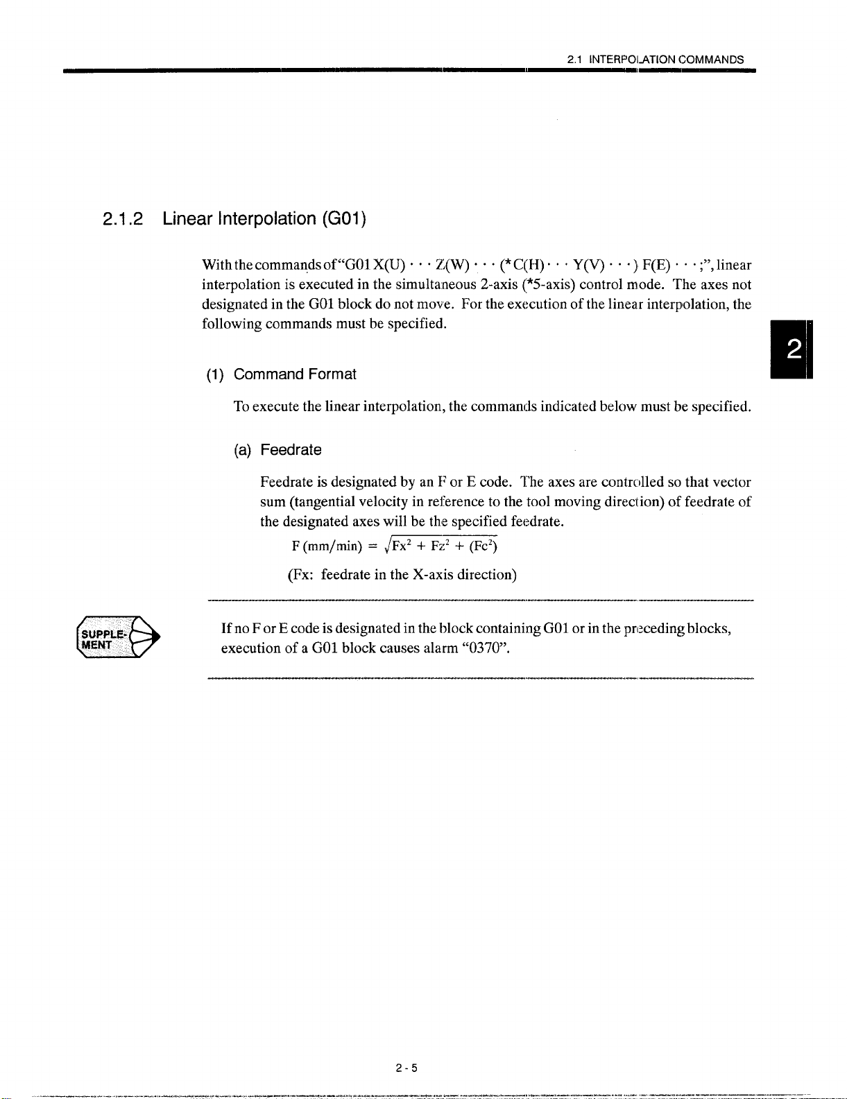
2.1,2 Linear Interpolation (GOI )
With thecommaqds of ’’GOl X(U) “ “ . Z(W) “ “ “ (*C(H)” “ “Y(V) . ““)1F(E) ‘ “ “;“,linear
interpolation is executed in the simultaneous 2-axis (*5-axis) control mode. The axes not
designated in the GO1 block do not move. For the execution of the linear interpolation, the
following commands must be specified.
(1) Command Format
To execute the linear interpolation, the commands indicated below must be specified.
(a) Feedrate
2.1 INTERPOLATION COMMANDS
SUPPLEMENT
(3)
Feedrate is designated by an For E code. The axes are controlled so that vector
sum (tangential velocity in reference to the tool moving direcltion) of feedrate of
the designated axes will be the specified feedrate.
F (mm/min) = ~Fx2 + FZ2+ (Fc2)
(Fx: feedrate in the X-axis direction)
If no F or E code is designated in the block containing GO1 or in the preceding blocks,
execution of a GO1 block causes alarm “0370”.
Page 43

● With an F code, axis feedrate is specified in either feed per spindle revolution
(mm/rev or inch/rev) or feed per minute (mm/min or inch/rein).
● If the optional C-axis is selected, the feedrate of X- and Z-axis and that of C-
axis differ from each other. Feedrates of these axes obtained by the same F
code are indicated in Table 2.2 below.
Table 2.2 Feedrates of X-/Z-axis and C-axis (F Command)
\\ I/,
POINT
n
‘Q’
Minimum F Command Unit
1 mm/min 1 deg/min
0.1 inch/rein
1 mm/min
0.0001 inch/rein
0.001 mm/min 0.0003937 degjmin
0.0001 inch/rein
2.54 deg/min
0.3937 deg/min
0.1 deglmin
0.001 deg/min
0.00254 deg/min
0.0001 deg/min
pm2004
DO=O
pm2004
DO=l
F Function
(Feed
mm output
inch output
mm output
—
inch output
per Minute)
mm input F60
inch input F51
mm input F60
inch input F51 0.1 inch/rein
mm input F63 0.001 mm/min
inch input F54
mm input
inch input F54
F63
Feedrate of X-/Z-axis Feedrate of C-axis
For the C-axis, a feedrate cannot be specified in the feed per minute mode.
2-6
Page 44

2.1 INTERPOLATION COMMANDS
(b) End Point
The endpoint can be specified in either incremental or absolute values corresponding to the designation of an address character or G90/G91. For details, see 3.2.1,
“Absolute/Incremental Programming”.
+x
1.
z
x
Programmed point
w
;
Present tool position
— +Z
e ~:~
Fig.2,3
Example of Programming
G50 X1OO. Z60.;
GOO T0202 S600 M03;
GO1 ZO F1.;
LinearInterpolation
x35. Z5.;
X60. FO.2;
Axes are
}
+x
I
mc
moved in the GO1 linear interpolation mcde,
D
)’
/
/
/
/
/
/
_________ ,. _. ._. ... .. . ._
Fig.2.4 Exampleof Programming
—.-— -—-—.. .—.-’..—--.. —.-
2-7
. . .--—-.——~
,—,.-... -——. .- .— .——.. —-——, —. —.-—-— -
Page 45
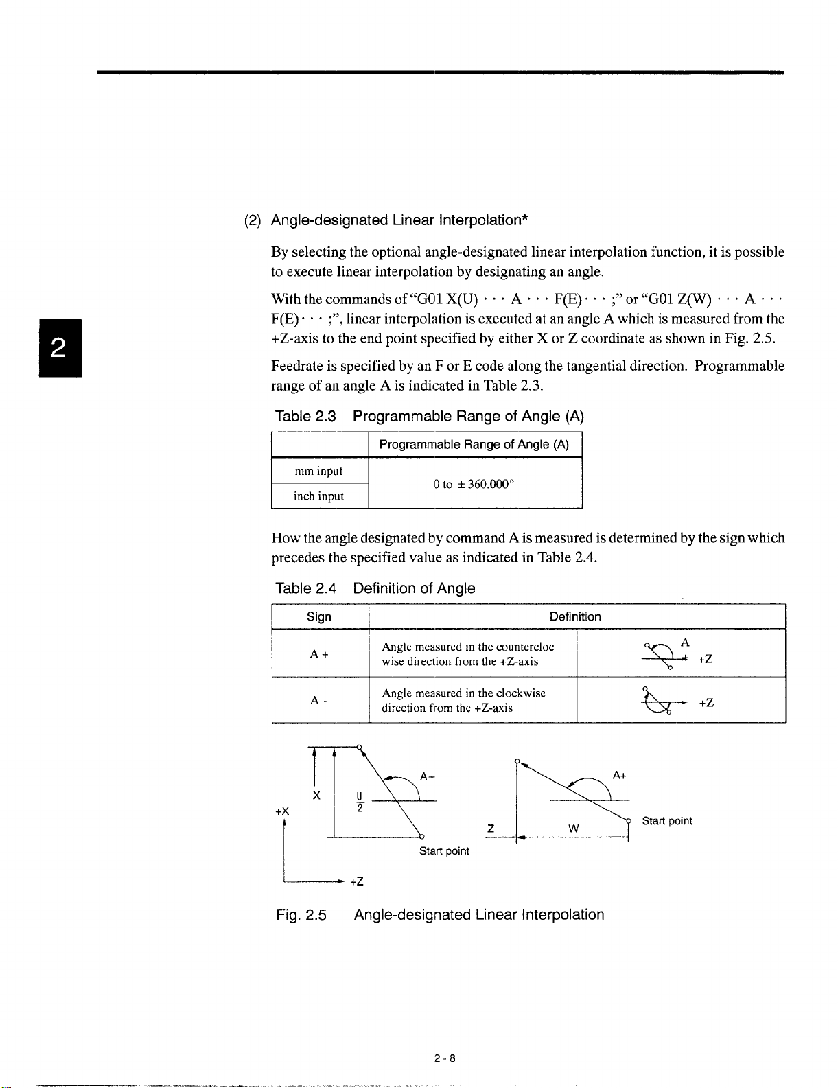
(2) Angle-designated Linear Interpolation*
By selecting the optional angle-designated linear interpolation function, it is possible
to execute linear interpolation by designating an angle.
With the commands of “GO1 X(U) “ 00 A “ “ “ F(E)” 0. ;“ or “GO1 Z(W) “ .0 A “ “ o
F(E) “ . “ ;“, linear interpolation is executed at an angle A which is measured from the
+Z-axis to the end point specified by either X or Z coordinate as shown in Fig. 2.5.
Feedrate is specified by an F or E code along the tangential direction. Programmable
range of an angle A is indicated in Table 2.3.
Table 2.3 Programmable Range of Angle (A)
Programmable Range of Angle (A)
E=
How the angle designated by command A is measured is determined by the sign which
precedes the specified value as indicated in Table 2.4.
Table 2.4 Definition of Angle
Definition
Angle
measured in the countercloc
l=-t-- *+Z
A-
x
+x
wise direction from the +.-axis
Angle measured in the clockwise
direction from the +.-axis
A+
$
b
Starl point
+Z
B
1
I
L-------
Fig. 2.5 Angle-designated
+Z
Start point
Linear Interpolation
2-8
Page 46
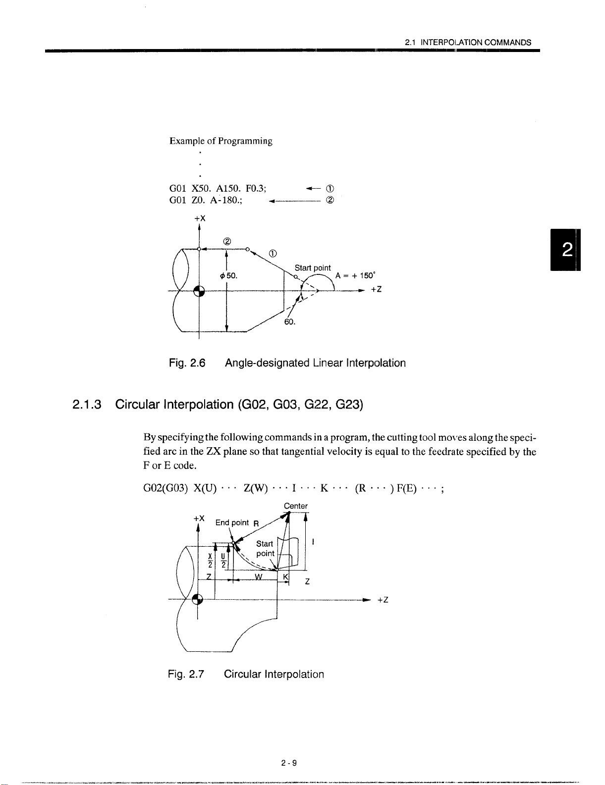
Example of Programming
2.1 INTERPOLATION COMMANDS
GO1 X50. A150. FO.3;
GO1 ZO. A-180.; .-
+— @)
@
+x
t
@
Fig. 2.6 Angle-designated Linear Interpolation
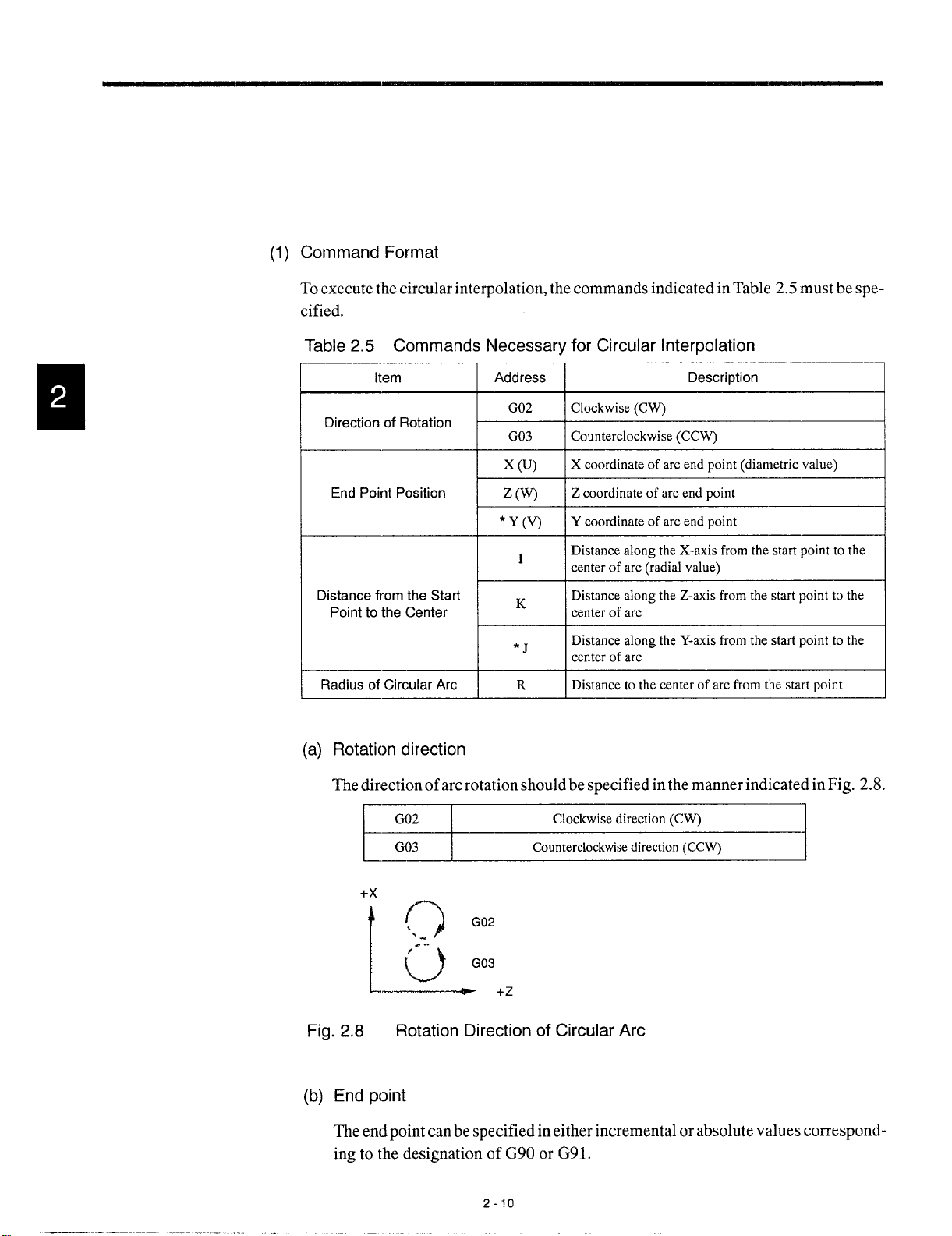
2.1.3 Circular Interpolation (G02, G03, G22, G23)
By specifying the following commands in a program, the cutting tool mo~’es along the specified arc in the ZX plane so that tangential velocity is equal to the feedrate specified by the
For E code.
G02(G03) X(U) .O” Z(W) ”C” I” C. K.””(R ““”) F(E).””;
Center
-—— +Z
Fig. 2.7 Circular Interpolaticm
2-9
——.——. ———=—.. —.——-. .—. -—-. —..—-—-. ——.. --... ———. —,—. .-—... ..—.-— ...—. ——.——... ..
Page 47
(1) Command Format
To execute the circular interpolation, the commands indicated in Table 2.5 must be specified.
Table 2.5 Commands Necessary for Circular Interpolation
Item
Direction of Rotation
End Point Position z (w)
Distance fromthe Start
Point to the Center centerof arc
Radius of Circular
(a) Rotation direction
The direction of arc rotation should be specified in the manner indicated in Fig. 2.8.
Arc R
G02
Address Description
G02
G03
x (u) X coordinate of arc end point (diametric value)
*Y(V)
I
K
*J
Clockwise (CW)
Counterclockwise (CCW)
Z
coordinate of arc end point
Y coordinate of arc end point
Distance along the X-axis from the start point to the
center of arc (radial value)
DistancealongtheZ-axisfromthe startpointto the
DistancealongtheY-axisfromthe startpointto the
centerofarc
Distance to the center of arc from the start point
Clockwise direction (CW)
Counterclockwisedirection (CCW)
+x
\
o
‘-
.-
/
0
[
—~
Fig. 2.8
(b) End point
The end point can be specified in either incremental or absolute values correspond-
ing to the designation of G90 or G91.
Rotation Direction of Circular Arc
G02
G03
+2
2-1o
I
Page 48

2.1 INTERPOLATION COMMANDS
If the specified end point is not on the specified arc, the arc radius i:; gradually
changed from the start point to the endpoint to generate a spiral so that the endpoint
lies on the specified arc.
Example of Programming
GO1 Z1OO. XO F1O.;
G03 Z-50. K-1OO.;
/
f
(
-
!50. O
100.
‘\
—---l-
\
100. z
Example of Programming
GO1 Z50. XO;
G03 Z- 100. K-50.;
Fig. 2.9
Interpolation with End Point off the Specified
-100
(a) End point positioned inside the circumference
1
I
i
(b) End point lying outside the circumference
Arc
Page 49

(c) Center of arc
The center of arccanbe specified in two methods - designation of the distance from
the start point to the center of the arc and designation of the radius of the arc.
I
End point
w
!;tart point
/
+x
z
—---
R
k
I
+2
‘qk[
;
.l-.–_._—
+P-
Center
.0”
K
--L
Fig. 2.10
c Specifying the distance from the start point to the center
Independent of the designated dimensioning mode (G90 or G91), the center
of an arc must be specified in incremental values referenced from the start
point.
● Specifying the radius
When defining an arc, it is possible to specify the radius by using address R
instead of specifying the center of the arc by addresses I or K. This is called
“circular interpolation with R desigmtion” mode.
o For the circular arc with the central angle of 180 deg. or smaller, use an R
value of “R > O“.
. For the circular arc with the central angle of 180 deg. or larger, use an R
value of “R < O“.
Example of Programming
.—— ———. —
Fig, 2.11
G02X(U) ””” Z(W) ””” R*”” ”F(E)”’ “;
or smaller
Start point
Circular interpolation with Radius R Designation
2-12
Page 50

2.1 INTERPCILATION COMMANDS
SJJPJLE-
C3
If an R command is used to specify the radius of an arc, G22 and (;23 can be used
instead of G02 and G03. When G22 or G23 is used, the programming format is the
same as used when G02 or G03 is specified with an exception of a G code. l[fG22 or
G23 is used, however, it is not allowed to define the center of the arc by I and K com-
mands. If these commands are used with G22 or G23, alarm “0162” occurs.
—
(2) Supplements to Circular Interpolation
A circular arc extending to multiple quadrants can be defined by the commands in a
single block.
Example of Programming
GOIZ””” F. O”;
G02 X60. Z-46.6 120. K-19.596 F . “. ;
\
\ AA
+x
@ 100.
27.
K
\
R28. “\
B
H
I ~
b 60.
I
—.——
Fig. 2.12 Circular Interpolation over Multiple Quadrants
Table 2.6
F==t=-&’;’m1
‘?
I
*
+Z
–428::–202 = –fi = –Ig.sgfj “m
Page 51

2.1.4 Chamfering (G11)
With thecommandsof’’Gll X(U) .00 K “ ‘ “ {orZ(W) .00 I “ c J}F(E) ~“ . ;“,chamfering
at corners is specified. In the designation of chamfering, single axis command of either Xaxis or Z-axis should be used.
Gll is a modal G code of 01 group. Once designated, it remains valid until other G code in
the 01 group is specified next.
(1) X-axis Chamfering
G1l X(U) O”. K+ ..” F(E)””;
——
L
Chamfer size
—
— Designation of chamfering direction
With the commands indicated above, X-axis chamfering is executed.
K- K+
End
point \
+x
t
L.-
+Z
Fig. 2.13 X-axis
\~ ‘
T
450
B
Start
point
Q
X (diametric value)
2
Chamfering
(2) Z-axis Chamfering
G1l Z(W) ”O” I+
““. F(E)”””;
—.
— Chamfer size (radial value)
t---!--
— Designation of chamfering direction
With the commands indicated above, Z-axis chamfering is executed.
End point
+1
-1
z
0’
b
450
1’
‘/
w
Start point
Fig. 2,14 Z-axis Chamfering
2-14
Page 52

Example of Programming
GOOX30. ZO;
Gll Z-20. 18. F30 ; — @
(Gil) X80. ,K-7. ;
7.
.— Q)
+x
20.
H+
2.1 lNTERPOLATION COMMANDS
SUPPLE.
MENT
(3
+Z
2.15 Example of Programming
Fig.
1. The following restrictions apply to the chamfer size K and I.
\KICIU/2],l 11<1 Wl
The K and I values must be smaller than the total move distance 1n the direction
of the designated axis. A formad error occurs if a value exceeding this limit is
specified.
2. Alarm “0445” occurs if both addresses X and Z are specified in the same block,
a block not including I or K is specified in the Gll mode, or I or K value is “O”.
3. The nose R offset offset function* is valid for the block where G 11 is specified.
4. It is possible to specify the Gll block in the commands of blocks that define fin-
ishing shape for a multiple repetitive cycle (G70 to G73).
5. It is possible to specify chamfering by specifying GO1 instead clf Gil.
GOIX(U) .”” K””” {or Z(W) ””” I.”} F(E) o“”;
.— _______ ____. — ._ -—... ..
2-15
— . . . .. —. —.. ,— .-,. =-—.. ,-< ..—. .—. ———-— —-—
Page 53

2.1.5 Rounding (G12)
With the commands of “G12 X(U) “ “ . K “ c “ {or Z(W) “ . “ I . “ “} F(E) o “ . ;“, corner
rounding is executed. In the designation, single axis command of either X-axis or Z-axis
should be used. Rounding is executed in a quarter circle.
G12 is a modal G code of 01 group. Once designated, it remains valid until other G code in
the 01 group is specified next.
(1) X-axis Rounding
G12X(U). ”.K* -“” F(E)..;
——
v-
I
————
— Designation of rounding direction
Rounding size
With the commands indicated above, X-axis rounding is executed.
K- K+
End
point
‘\
+x
t
L._
-
Fig. 2,16 X-axis Rounding
T
+Z
Start point
u
T
2
)( (diametric
value)
(2) Z-axis Rounding
G12Z(W)””” I* ““. F(E) ”.o;
~ –L—
~—
Rounding size (radial value)
Designating of rounding direction
—-. ..
With the commands indicated above, Z-axis rounding is executed.
End point
+1
—.. - —
-1
/
/
---1--w
Start point
a
I
Fig. 2.17 Z-axis Rounc!ing
2-16
Page 54

Example of Programming
GOO X20. ZO ;
G12 Z-25. 19. F30 ;
(G12) X70. K-6. F20 ;
6.
$70.
9.
— (b
+ @
25.
@
——
o
2.1 INTERPOLATION COMMANDS
+x
$20.
G’:
J
Fig. 2.18 Example of Programming
1. The following restrictions apply to the rounding size K and 1.
lKl<lU/21,111<lWl
The K and I values must be sma”ller than the total move distance in the direction
of the designated axis. A format error occurs if a value
specified.
2. Alarm “0445” occurs if both addresses X and Z are specified in Ihe same block,
a block not including I or K is specified in the G12 mode, or I or K value is “O”.
exceeding this limit is
3. The nose R offset offset function* is valid for the block where G12 is specified.
4. It is possible to specify the G12 block in the commands of blocks that define finishing shape for a multiple repetitive cycle (G70 to G73).
5. It is possible to specify chamfering by specifying GO1 instead clf G12.
GOIX(U) ””” R.. ”{or Z(W) ””” R”””} F@)”””;
.
2-17
.—— — .—— —.-. .-— .. —-. .—- —
—.—
,=..—.. .— ..
——
—..—.————. .
Page 55

2.1.6 Cylindrical Interpolation (GI 24, G125) *
The cylindrical interpolation function allows programming of machining on a cylindrical
workpiece (grooving on a cylindrical workpiece) in the manner like writing a program in a
plane using the cylinder developed coordinate system. This functions allows programming
both in absolute commands (C, Z) and incremental commands (H, W).
(1) Programming Format
(a) Features of GI 24, G 125
The following G codes are used for cylindrical interpolation.
Table 2,7 G Codes Used for Cylindrical Interpolation
Cylindrical interpolation mode ON
Group
e ‘“”’’ion :
Cylindrical interpolation mode OFF
These G codes are buffering prohibiting G codes.
Specify G124 and G125 in a block without other commands. If other G code is
specified with G124 or G125 in the same block, alarm “0161” (UNMATCH G
CODE) occurs,
G124 and G125 are modal G codes of 20 group. Once G124 is specified, the cylin-
drical interpolation mode ON state remains until G125 is specified. When the power is turned ON or the NC is reset, the G125 (cylindrical interpolation mode OFF)
state is set.
(b) Programming format
Cylindrical interpolation mode ON
G124CO”. ;
+
-=--Machining program in the cylindrical interpolation mode
G125 ;
+ Cylindrical interpolation mode OFF
where, C = Radius of cylindrical workpiece
(1 = 0.001 mm or 0.0001 inch)
‘Theradius of a cylindrical workpiece must always be specified. If a C command
is not specified, alarm “0162” (LACK OF ADDRESS) occurs.
2-18
Page 56

Feedrate
(c)
In the cylindrical interpolation mode, interpolation is executecl in the virtual C-Z
plane. Therefore, after the entry to the cylindrical interpolation. mode, it is necessary to specify feedrates in the C-Z plane.
value represents feedrates (mrn/min, inchhnin) in the C-Z plane.
● For cylindrical interpolation, use the G98 (feed per minute) mode. Cylindrical
interpolation is not possible in the GOOmode. To execute ~Jositiorling, cancel
the cylindrical interpolation mode. Note that GOOmode nlay be specified in
a plane other than the C-Z plane.
(2) Example of Programming
2.1 INTERPOLATION COMMANDS
lJse address F to specify feedrates. F
Cu”ng’oo’u----z
Example of programming
0100 ;
G98 ;
TO1O1;
GOOX44.O CO; .—
G124 C45.O ; c—
GO1 G42 Z47.5 F1OO;
C60.O;
Z32.5 C120.O ;
C240.O;
G03Z40.OC249.549R7.5;
G02Z47.5C259.099R7.5;
GO1C360.O;
G40Z44.O;
G125;
M30; —
c
Positioning at the start point c,f cutting
Cylindrical interpolation mode ON
Machining program
1
Cylindrical interpolation mode OFF
Fig. 2.19 Coordinate System for Cylindrical Interpolation
———— ,.———=—..=— ... .... .. ... ..— ,,.—.—-.” .-. .
2-19
—.. -
——., —. —. —. —.. .-~ -=—— -.”-. ——. +—.. --—
Page 57

Relationships between Cylindrical Interpolation and Operations
(3)
In the cylindrical interpolation mode, the following G codes maybe specified: (GOO),
GO1, G02, G03, G04, G1O, G22, G23, G40, G41, G42, G65, G66, G67, (G90, G91),
G98, and G134. Alarm “0161” (UNMATCH G CODE) occurs if a G code other than
those indicated above is specified in the cylindrical interpolation mode.
1. In the GOOmode, only X.-axis can be specified.
2. G90 and G91 are valid only when special G code specification is selected.
3, In the G134 mode, only M commands maybe specified.
●
In the cylindrical interpolation mode, the tool radius offset function can be
used. Turning ON/OFF of the tool radius offset function must be made in the
cylindrical interpolation mode. The tool radius offset function is valid only
in the cylindrical interpolation mode and the polar coordinate interpolation
mode.
●
In the cylindrical interpolation mode, cutting in the linear interpolation (GO1)
mode and circular interpolation (G02/G03) mode is available. Circular interpolation is permitted only in the C-Z plane. If circular interpolation commands are specified in other plane, an alarm occurs. For the definition of an
arc, use either addresses I and K to specify the center of arc or address R to
directly specify the radius of the arc. Note that designation of address R is optional.
●
The nose R offset function must be canceled before specifying G124.
●
It is not allowed to specify G124 with the mirror image function ON. Similarly, it is not allowed to turn ON the mirror image function in the G124 mode.
If the mirror image function is turned ON in the G124 mode, an alarm occurs.
●
Tand S commands must not be specified in the cylindrical interpolation mode.
Designation of M commands is possible in the cylindrical interpolation mode.
●
The spindle function is invalid in the cylindrical interpolation mode.
●
In the cylindrical interpolation mode, the manual absolute function is fixed to
OFF.
2-20
Page 58
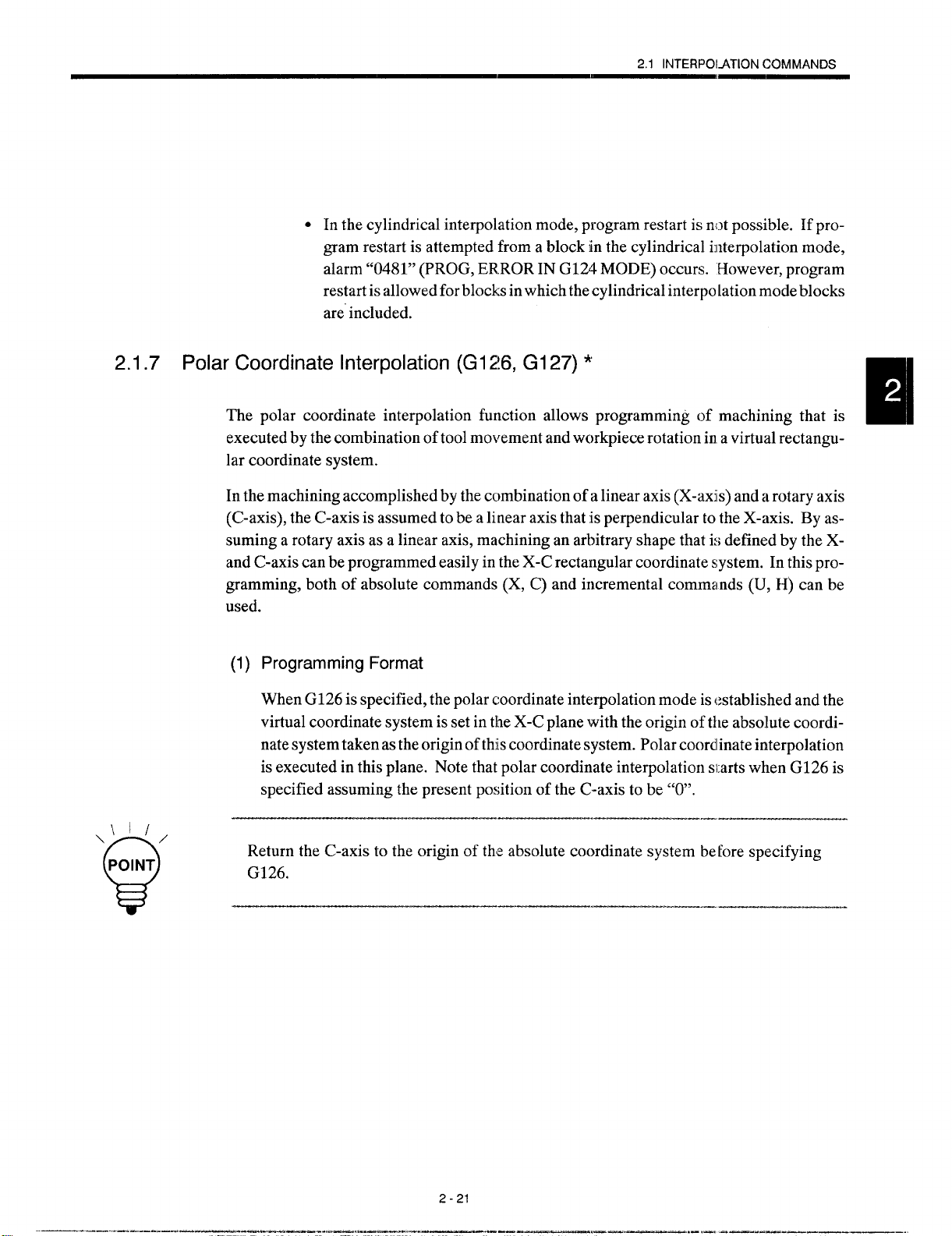
● In the cylindrical interpolation mode, program restart is not possible. If pro-
gram restart is attempted from a block in the cylindrical interpolation mode,
alarm “0481” (PROG, ER.ROR IN G124 MODE) occurs.
restart is allowed for blocks in which the cylindrical interpolation mode blocks
are” included.
2.1.7 Polar Coordinate Interpolation (GI 2!6, G127) *
The polar coordinate interpolation function allows programming of machining that is
executed by the combination of tool movement and workpiece rotation in,a virtual rectangu-
lar coordinate system.
In the machining accomplished by the combination of a linear axis (X-axis) and a rotary axis
(C-axis), the C-axis is assumed to be a linear axis that is perpendicular to the X-axis. By assuming a rotary axis as a linear axis, machining an arbitrary shape that is defined by the Xand C-axis can be programmed easily in the X-C rectangular coordinate system. In this programming, both of absolute commands (X, C) and incremental commands (U, H) can be
used.
2.1 INTERPOLATION COMMANDS
However, program
\\
I//
POINT
Q
(1) Programming Format
When G126 is specified, the polar coordinate interpolation mode is established and the
virtual coordinate system is set in the X-C plane with the origin oft] le absolute coordinate system taken as the origin of this coordinate system. Polar
is executed in this plane. Note that polar coordinate interpolation si:arts when G126 is
specified assuming the present position of the C-axis to be “O”.
Return the C-axis to the origin of the absolute coordinate system before specifying
G126.
coordinate interpolation
————_
————-—-.——.—._—. .—.’—— ... .
2-21
.—— .—,—. .- .— .- —.. —. ——— ——
Page 59

(a) Features ofG126 ancjG127
The following G codes are used to turn ON/OFF the polar coordinate interpolation
mode.
Table 2.8 G Codes Used for Turning ON/O FFthe Polar Coordinate interpola-
tion
~GW~ F.n.ti.n
Polar coordinate interpolation mode ON
~“
G127
L
Specify G126 and G12’7 in a block without other commands. If other G code is
specified with G126 or G127 in the same block, alarm “0161” (UNMATCH G
CODE) occurs.
G126 and G127 are moclal G codes of 19 group. Once G126 is specified, the polar
coordinate interpolation mode ON state remains until G127 is specified. When the
power is turned ON or the NC is reset, the G127 (polar coordinate interpolation
mode OFF) state is set.
(b)
Feed rates
In the polar coordinate interpolation mode, interpolation is executed in the X-C
plane. It is necessary to specify feedrates after entering the polar coordinate interpolation mode. For the designation of feedrates, use address F. Feedrate F expresses feedrates (mm/min, inch/rein) in the X-C plane. In the polar coordinate interpolation mode, specify feedrates in the G98 (feed per minute) mode. It is not
possible to specify GOO(G codes that include rapid traverse cycle). To execute
positioning, cancel the polar coordinate interpolation mode. It is allowed to specify
GOOin a plane other than the X-C plane.
Polar coordinate interpolation mode OFF I 19 I
I
Group
19
7
—
—
1
o Restrictions on feedrates
The following must be satisfied so that the actual speed of the rotary axis does
not exceed rapid traverse rate:
F/D S (n/360) ;< (Rapid traverse rate of rotary axis)
F (mm/ rein) : F command x Feed override
D (mm) : Diametric value when a cutting tool approaches closest
to the workpiece center
(tool paths after offset if the tool radius offset function
is used.)
2-22
Page 60
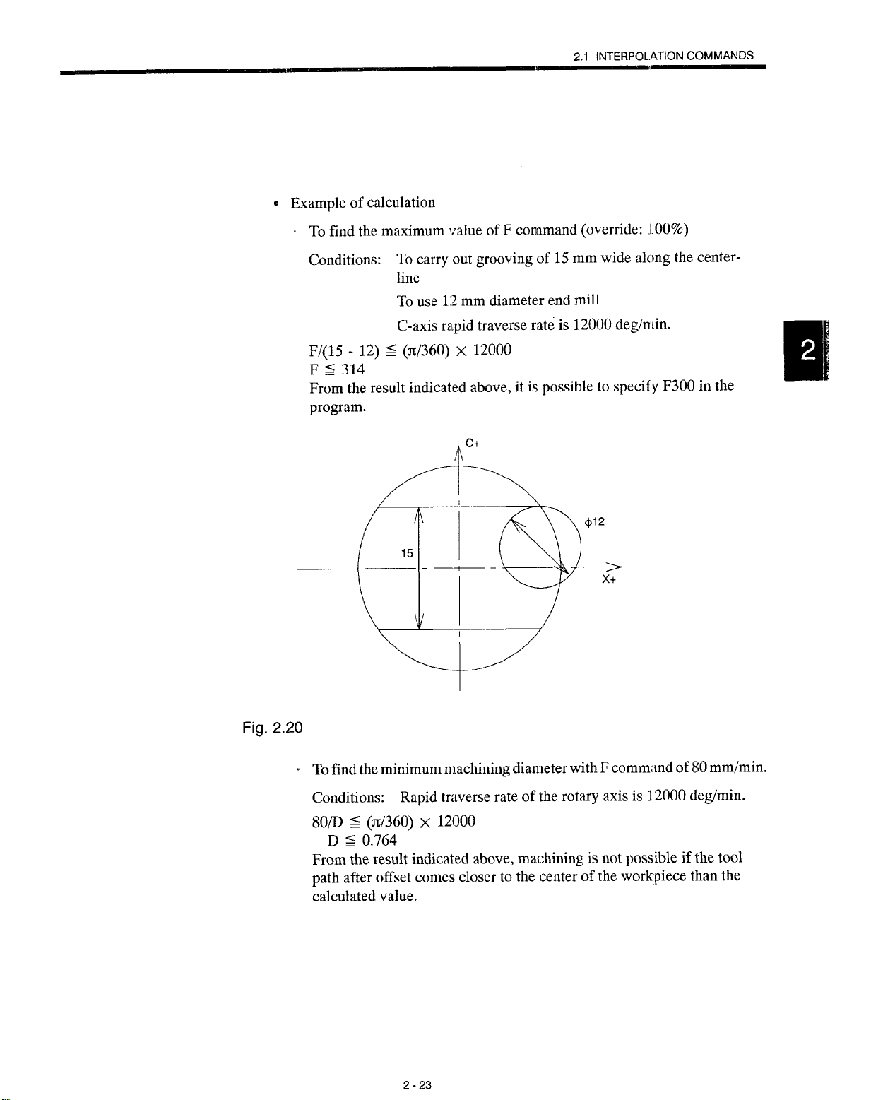
2.1 INTEFIPOL.ATION COMMANDS
—
e Example of calculation
To find the maximum value of F command (override: 1.00%)
Conditions:
To carry out grooving of 15 mm wide akmg the centerline
To use 12 mm diameter end mill
C-axis rapid traverse rate is 12000 deghin.
F/(15 - 12) S (z/360) X 12000
F 5314
From the result indicated above, it is possible to specify F300 in the
program.
c+
A
+12
>
x+
———. ———. —
—-
Fig. 2.20
To find the minimum machining diameter with F comm;md of 80 mm/min.
Conditions:
80/D S (n/360) X
Rapid traverse rate of the rotary axis is 12000 deg/min.
12000
D S 0.764
From the result indicated above, machining is not possible if the tool
path after offset comes closer to the center of the work piece than the
calculated value.
2-23
-
———.
. .—-..
.. ,- .—
..=. —
-.,
Page 61
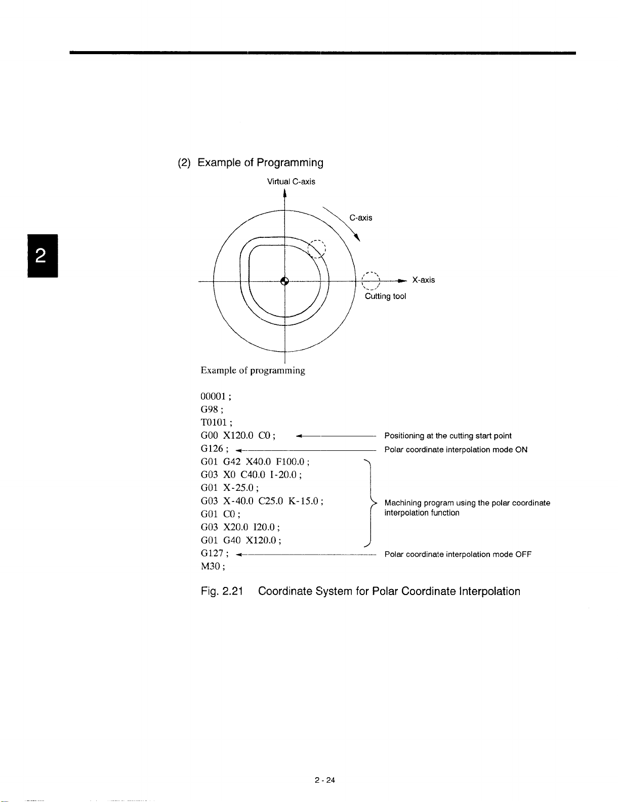
(2) Example of Programming
Virtual C-axis
!
.
A \
Example of programming
00001 ;
G98 ;
TO1O1;
GOOX120.O CO; —
G126 ; GO1
G42 X40.O
XO C40.O 1-20.0;
G03
X-25.O ;
GO1
X-40.O C25.O K-15.O ;
G03
co;
GO1
X20.O 120.0;
G03
G40 X120.O ;
GO1
F1OO.O;
G127 ; M30 ;
—
1,
i.
-.’
Cutting tool
X-axis
-
Positioning at the cutting start point
Polar coordinate interpolation mode ON
Machining program using the polar coordinate
interpolation function
1
Polar coordinate interpolation mode OFF
Fig. 2.21 Coordinate System for Polar Coordinate Interpolation
2-24
Page 62
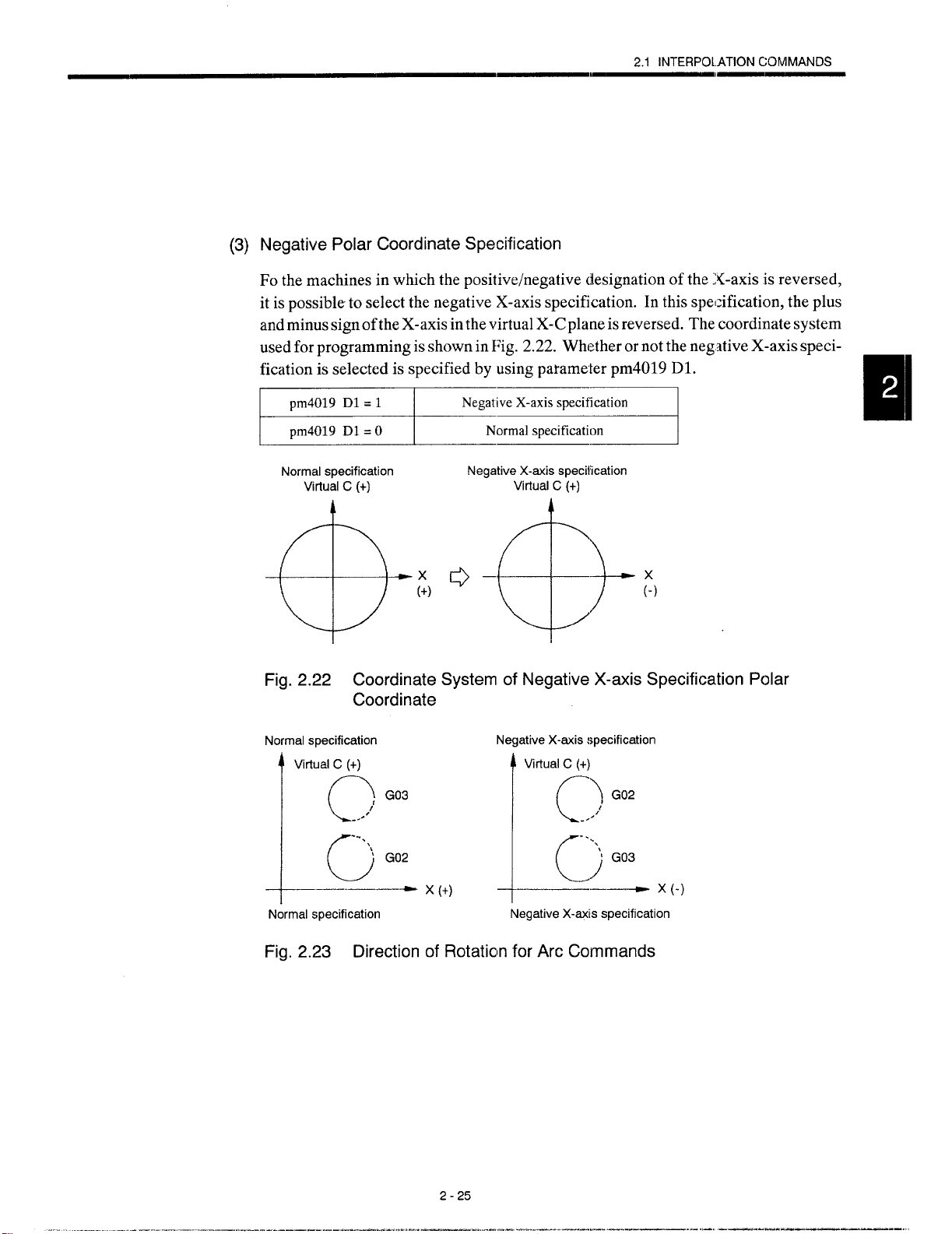
2.1 INTERPOLATION COMMANDS
(3) Negative Polar Coordinate Specification
Fo the machines in which the positive/negative designation of the X-axis is reversed,
it is possible to select the negative X-axis specification. In this specification, the plus
and minus sign of the X-axis in the virtual X- Cplane is reversed. The coordinate system
used for programming is shown in Fig. 2.22. Whether or not the neg.~tive X-axis specification is selected is specified by using parameter pm4019 D1.
pm4019 D1 = 1
pm4019 D1 = O Normal specification
Normal specification
Virtual C (+)
Q’)”-Q:)
Fig. 2.22 Coordinate System of Negative X-axis Specification Polar
Coordinate
Normal specification
Virtual C (+)
, G03
/’
..-
P
-“.
‘$
‘ G02
G
1-
—.—
Normal specification
—
NegativeX-axisspecification
Negative X-axis specification
Virtual C (+)
Negative X-axis specification
Virtual C (+)
x (+)
i-
Negative X-axis specification
“=
~)
/’
.. .
. . .
) ’03
c
~ x (-)
G02
Fig. 2.23 Direction of Rotaticm for Arc Commands
2-25
Page 63
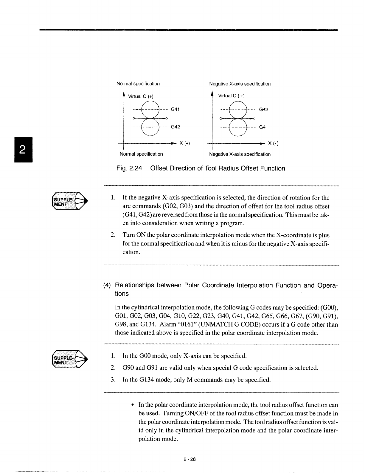
Normal specification
Negative X-axis specification
SUPPt.E-
MENT
CD
-1-
I
Virtual C (+)
o
——
x(-)
—
Virtual C (+)
-------- .—(
-------- -—
-(
~-3
+—
I
Normal specification Negative X-axis specification
Fig. 2.24 Offset Direction of Tool Radius Offset Function
1. If the negative X-axis specification is selected, the direction of rotation for the
arc commands (G02, G03) and the direction of offset for the tool radius offset
(G41, G42) are reversed from those in the normal specification. This must be taken into consideration when writing a program.
2. Turn ON the polar coordinate interpolation mode when the X-coordinate is plus
for the normal specification and when it is minus for the negative X-axis specification.
G41
G42
-m- x (+)
SIJPPLEMENT
cl)
(4) Relationships between Polar Coordinate Interpolation Function and Opera-
tions
In the cylindrical interpolation mode, the following G codes maybe specified: (GOO),
GO1, G02, G03, G04, G1O, 022, G23, G40, G41, G42, G65, G66, G67, (G90, G91),
G98, and G 134. Alarm “0161° (UNMATCH G CODE) occurs if a G code other than
those indicated above is specified in the polar coordinate interpolation mode.
1. In the GOOmode, only X-axis can be specified.
2. G90 and G91 are valid only when special G code specification is selected.
3. In the G134 mode, only M commands maybe specified.
—
● In the polar coordinate interpolation mode, the tool radius offset function can
be used. Turning CIN/OFF of the tool radius offset function must be made in
the polar coordinate interpolation mode. The tool radius offset function is valid only in the cylindrical interpolation mode and the polar coordinate interpolation mode.
2-26
—---
Page 64

2.1 INTERPOLATION COMMANDS
M In the polar coordinate interpolation mode, cutting in the linear interpolation
(GO1) mode and circular interpolation (G02/G03) mode. Circular interpola-
tion is permitted only in the X-C plane. If circular interpolation commands
are specified in other plane, an alarm occurs. For the definition of an arc, use
either addresses I and K to specify the center of arc or address R to directly
specify the radius of the arc. Note that designation of add:ess R is optional.
. The nose R offset function must be canceled before speci~ying G126.
● It is not allowed to specify G126 with the mirror image function ON. Similar-
ly, it is not allowed to turn ON the mirror image function in the G124 mode.
If the mirror image functicn is turned ON in the G126 mode, an alarm occurs.
● T and S commands must not be specified in the polar coordinate interpolation
mode. Designation of M commands is possible in the polar coordinate interpolation mode.
● The spindle function is invalid in the polar coordinate inkxpolation mode.
. In the polar coordinate interpolation mode, the manual alxolute function is
fixed to OFF.
● In the polar coordinate interpolation mode, program restart is not possible. If
program restart is attempted from a block in the polar coordinate interpolation
mode, alarm “0483” (PROG, ERROR IN G126 MODE) occurs. However,
program restart is allowecl for blocks in which the cylindrical interpolation
mode blocks are included.
● If a command that causes the tool paths to pass the center of the polar coordi-
nate in the polar coordinate interpolation mode, alarm “0483” occurs since the
C-axis feedrate becomes infinite.
- In the polar coordinate interpolation mode, selection is possible for the X- and
C-axis commands whether they are specified in diametric values or radial values.
X- and C-axis commands are specified irldiameter.
* ‘--i
X- and C-axis commands are specified in radius.
——— —.-——— ..—
2-27
-.
—
.- —-. ——
Page 65
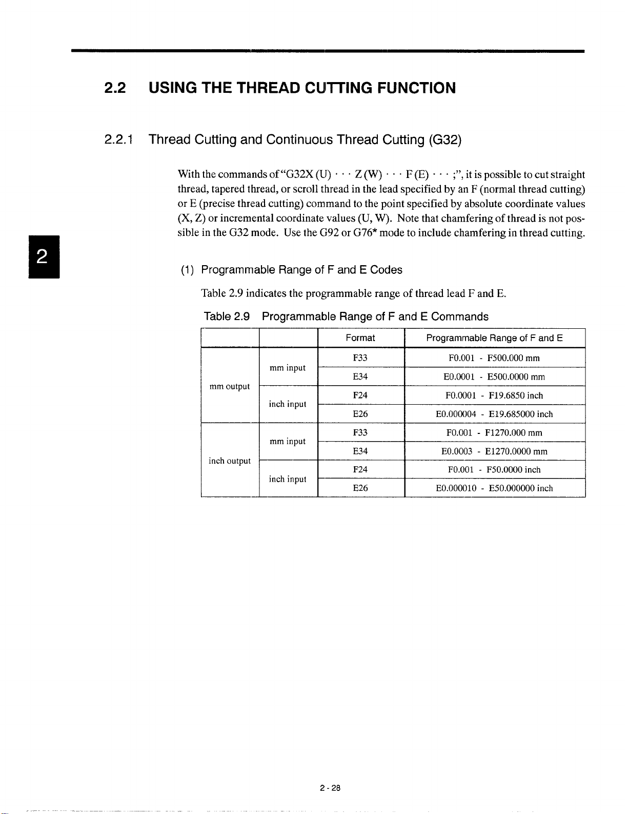
2.2 USING THE THREAD CUllTING FUNCTION
2.2.1 Thread Cutting and Continuous Thread Cutting (G32)
With the commands of “G32X (U) 00 “ Z (W) . “ “ F (E) “ “ “
;“, it is possible to cut straight
thread, tapered thread, or scroll thread in the lead specified by an F (normal thread cutting)
or E @recise thread cutting) command to the point specified by absolute coordinate values
(X, Z) or incremental coordinate values (U, W). Note that chamfering of thread is not possible in the G32 mode. Use the CJ92or G76* mode to include chamfering in thread cutting.
(1) Programmable Range of F and E Codes
Table 2.9 indicates the programmable range of thread lead F and E.
Table 2.9 Programmable Range of F and E Commands
Format Programmable Range of F and E
mm input
F33
E34 EO.0001 - E500.0000 mm
mm output
F24 FO.0001 - F19.6850 inch
inch input
E26
F33 FO.001 - F1270.000 mm
mm input
E34 EO.0003 - E1270.0000 mm
inch output
F24
inch input
E26
FO.001 - F500.000 mm
—
EO.000004 - E19.685000 inch
—
FO.001 - F50.0000 inch
EO.OOOO1O- E50.000000 inch
—
—
2-28
Page 66

2.2 USING THE THREAD CUITING FUNCTION
(2) Direction of Thread Lead
The direction of thread lead specified by the F and E commands is indicated in
Table 2.10.
Table 2.10 Direction of Threacl Lead
Taper Angle a
I -4
(X!Z)<
‘~+~ “. -’—~
Fig. 2.25 Thread Cutting
(3) Restrictions on F and E by Spindle Speed S
I as LISO I L-MCIintheZ-a:cis direction stmtikf be specified. I
Lead in the X-axis direction should be specified.
Direction of Thread Lead
—,
+Z
As indicated in Table 2.11, there are restrictions on the designation of F and E commands by Table 2. llspindle speed S. Concerning the X-axis feedrate component, its
upper limit is 1/2 of the values indicated in Table 2.11.
Table 2.11 Restrictions on F and E Commands by Spindle :Speed S
I inch output I
F (E) x S S 24,000 inch/rein
I
Page 67

(4) Programming Formats
Programming formats of thread cutting are indicated in Table 2.12.
Table 2.12 Programming Formats of Thread Cutting
Thread Type
Normal G31 Z(W) ...;...;
Straight thread
Precision G32Z(W). .. E;..;
Normal G32X(U) . .. Z(FO. .F O...
Tapered thread
Precision G32X(U) 0.. Z(Wj. .. E...;
Normal G32 X(U) ...;...; –
Scroll thread
Precision G32 X(U) ...;...;
● Example of programming for cutting straight thread
Command Format
Thread lead L = 5.0 mm
5.0 mm
al =
IS2 = 3.0 mm
Depth of cut per pass = 1.0 mm
+-x
GOOU-42. ; _—
@
b
G32 W-68. F5.O ; ~@
GOOU 42. ;
:---;-w 68. ;
u-44. ;
G32 W-68. ;
+.
GOOU 44. ;
I
~~
——
—
.
—
3—.
+Z
Fig, 2,26 Example of Programming for Cutting Straight Thread
2-30
Page 68

2.2 [JSING THE THREAD CUl_HNG FUNCTION
● Example of programming for cutting tapered thread
Thread lead
Depth of cut per pass= 1.0 rnm
L = 4.0 rnm
& = 3.0 rnm
52 = 2.0 rnm
GOOX13. _—
G32 X38. W-35. F4.O;
GOOX60. ;
W35. ;
X11. ;
G32 X36. W-35. ;
GOOX60.;
+x
0
+@
-Y
I
r—r-’---
:“
,,
I
%-- L-=---l
Fig. 2.27 Example of Programming for Cutting Tapered Ttread
2-31
——.+.-.———— .—————... . .—
Page 69

(5) Continuous Thread Cutting
Since the N-Chas buffer register, designation for continuous thread cutting is possible.
In addition, continuous threads can be cut smoothly because the block-to-block pause
time is “O” for thread cutting command blocks.
Example of Programming
\\ I//
POINT
Q
G32X(U) ””” Z(W) .” F(E)”””;
G32X(U)””” Z(W)”.; .—.—
G32X(U). ”” Z(W)”””;
0
(2
—--—.---—.
—Cl
1
;
—a
@
[5
ml
(a) Reinforced pipe coupling
Fig. 2.28 Continuous Thread Cutting
1. If designation of thread lead (F, E) is changed during thread cutting cycle, lead
accuracy is lost at joints of blocks. Therefore, thread lead designation must not
be changed during threacl cutting cycle.
2. If continuous thread cutting is specified, M codes must not be specified. If an M
code is specified, the cycle is suspended at the specified block and continuous
thread cannot be cut.
(b) Worm screw
2-32
Page 70

2.2 USING THE THREAD ICUITING FUNCTION
(6) Margin for Incomplete Thread Portions (81, 62)
At the start and end of thread cutting, lead error is generated. Therefore, margins al and
82 should be given at the start and end portions in thread cutting,
+x
-+--_--.--f-+,
Fig. 2.29 Margins for Incomplete Threads
These margins 61 and b2 can be calculated as indicated in Table 2,13.
Table 2.13 Calculation of Margins for Incomplete Thread Portions
&
62
Approximate Value Meaning
(mm) : Thread lead
L
51> &(ln;-1)
62>&
S (r / rein) :
K : Constant (normally 30)
a(-)
In
Spindle speed
: Thread accuracy
–L . . . .
—
L
: Natural logarithm (log)
——
(Lead error)
EEE!EE3=EI
Example of calculation
Thread lead L = 3.0 mm
Spindle speed S = 5.0 r/rein
Thread accuracy =1/100
61 and b2for this case
1
61> ~(hl~-1) – 3.0
* , L*S
–3.0x500.=083rnm
60”K 60”K “
—
X 50(I
60 “K
x 3.61 = 3.0 mm
Page 71

\\ I/,
POINT
o
v
~tiiia)
2.2.2 Multiple-thread Cutting (G32) *
Multiple-thread cutting (multiple threads in alead) is possible without shifting the thread cutting start point. In thread cutting operation, axis feed starts in synchronization with the startpoint pulse (1 pulse/turn) output from the spindle pulse generator attached to the spindle.
Therefore, the thread cutting start point is always at the same point on the workpiece circumference. In multiple-thread cutting operation, axis feed starts when the spindle rotates by a
certain angle after the output of the start-point pulse from the spindle pulse generator.
Keep the spindle speed at the same value until one thread is cut. If the spindle speed
is not maintained constant, accuracy could be lost due to servo lag.
———
1. During thread cutting, override operation and feed hold operation are disregarded.
2. If G32 is specified in the G98 (feed per minute) mode, alarm “0452” occurs.
3. If a thread cutting command is executed in the dry run mode, axes move at the
jog feedrate.
Lead
--———.-
Fig, 2.30 Double-start Thread
With the commands of “G32 X (U) “ “ o Z (W) . “ “ F (E) “ “ “ B “ “ o ;“, the spindle rotates
by the angle specified by address 11after the output of the start-point pulse of the spindle pulse
generator. After that thread cutting starts toward the point specified by X (U) and Z (W) at
the lead specified by an For E cc)mmand.
J
234
Page 72

2.2 USING THE THREAD CUTTING FUNCTION
——
(1) Address B Specified in Multi-thread Cutting
Least input increment : 0.0010
Programmable range : 0 S B <360.000
If decimal point input is used, “B1.” is equal to 10 (B1. = 10). B commands are nonmodal and valid only in the specified block.
(2) Number of Threads and B Command
In general, the thread cutting start points lie on the workpiece circumference; the intervals of these points are calculated by dividing 3600 by the number of t breads. Examples
of multiple threads (double-start, triple-start, and quadra-start thre ads) are shown in
Fig. 2.31.
Thread cutting start point
- double-start thread
1st thread :
2nd thread: B180.
Fig. 2.31
No B command
Number of Threads and B Commands
Thread cutting start point
- tripla-start thread
1st thread : No B command
2nd thread: B120.
3rd thread : B240.
Thread xtting sfart point
- quadra-start thread
1st thread :
2nd threacl: B90.
3rd thread : B1 80.
4th thread : B270,
No B command
2-35
Page 73

(3) Spindle Rotating Angle from Start-point Pulse Specified by B Command
For the designation of spinclle rotating angle measured from the start-point pulse, the
least detectable increment is 360°/4096 pulses ~ 0.08790/pulse since the pulses output
from the spindle pulse generator (4096 pulses/rotation) are used. For a B command,
an error of ~ 1 pulse of the spindle rotation detection pulses could be generated. An
example of programming for double-start thread is indicated below.
Example of Programming
GOOU..;
G32W”. ”F ”.”;
GOOU..;
w“””;
. . . .
u
G32W U”;
Thread cutting of thread A
)
suPPt.E-
MEWf
(3
GOOU O”;
G32 W . . “ B180. ;
GOOU”.;
w“””;
. . . .
u
G32WU”
Fig. 2.32 Spindle Rotation Angle from Start-point Pulse by E)Command
1. If a B command value is outside the programmable range (O to 360.000), alarm
“0453” occurs,
2. If a B cc)mmand is specified for multiple-thread cutting, continuous thread cutting is not possible.
G32W . . . . B90
G32W . . . .
3. The spindle rotation angle from the start-point pulse is specified using a B com-
mand (C+to 360°) disreg~rding of the spindle rotating direction.
B180. ;
+ Since the operation is suspended at this block to wait for the
start-point pulse, continuous thread cannot be cut.
--)
Thread cutting of thread B
~
2-36
Page 74
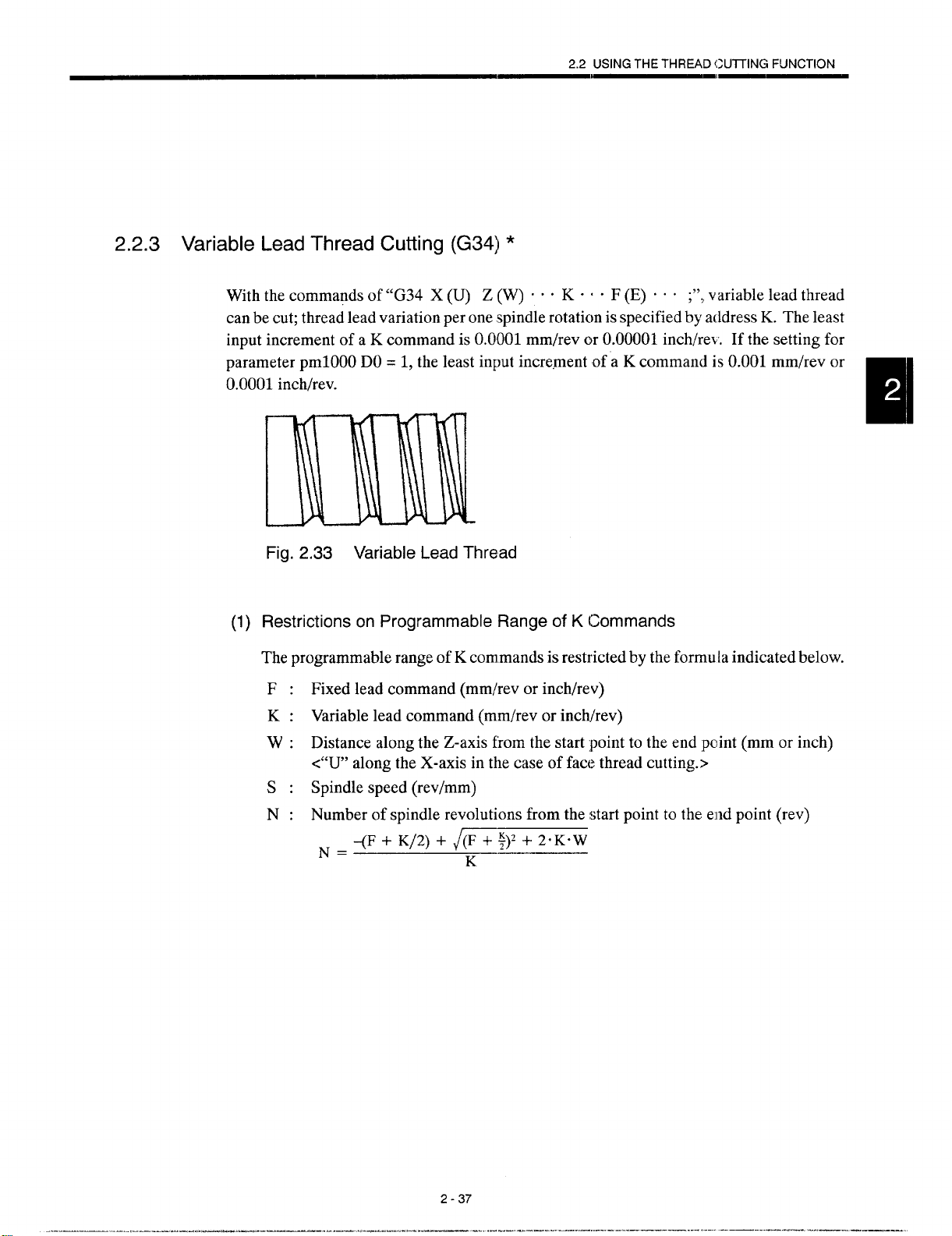
2.2.3 Variable Lead Thread Cutting (G34)*
With the commands of “G34 X (U) Z (W) c “ “ K “ ‘ “ F (E) . “ “ ;“, variable lead thread
can be cut; thread lead variation per one spindle rotation is specified by address K. The least
input increment of a K command is 0.0001 mm/rev or 0.00001 inch/re~. If the setting for
parameter pm1000 DO = 1, the least input increment of a K command is 0.001 mm/rev or
0.0001 inch/rev.
2.2 USING THE THREAD ICUITING FUNCTION
Fig. 2.33 Variable Lead Thread
(1) Restrictions on Programmable Range of K Commands
The programmable range of K commands is restricted by the formula indicated below.
F: Fixed lead command (mm/rev or inch/rev)
K: Variable lead command (mm/rev or inch/rev)
w: Distance along the Z-axis from the start point to the end pclint (mm or inch)
<“u” along the X-axis in the case of face thread cutting.>
s: Spindle speed (rev/mm)
N: Number of spindle revolutions from the start point to the end point (rev)
~ . -(F+ K/2) + ~:)z + 2“K”W
K
Page 75

Feedrate at End Point
(2)
Specify the commands so that the feedrate at the end point will not exceed the upper
limit indicated in Table 2.14.
Table 2.14 Upper Limit of Feedrate at End Point
T__l___ upper~mit
==+---+=+
S x (F + ~ + KN) S pm2800 (Max. cutting feedrate)
Feedrate at End Point
(3)
Specify the commands so that the feedrate at the end point will not be a negative value.
(F+~)2+2KW>0
1. In the continuous block thread cutting for variable lead thread cutting, distribu-
tion of command pulses is interrupted at joints between blocks.
2. If a K command is outside the programmable range, alarm “0450” occurs.
3. If G34 is executed in the dry run mode, the axes move at a feedrate designated
for the jog feedrate if “parameter pm2000 D1 = l“.
4. If address B is designated in the G34 block, alarm “0450” occurs.
Page 76
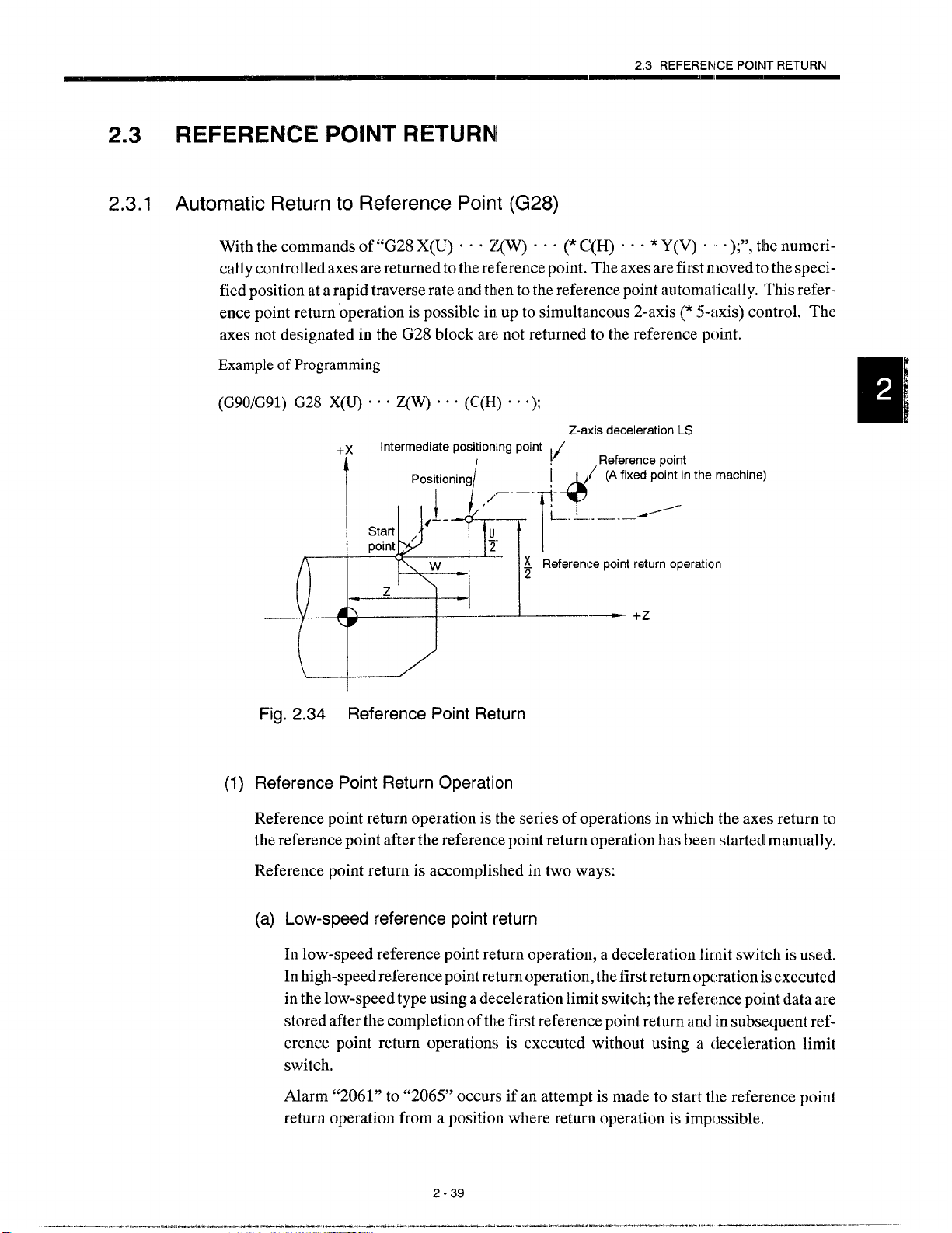
2.3 REFERENCE POINT RETURN
2.3
REFERENCE POINT RETURN
2.3.1 Automatic Return to Reference Point (G28)
With the commands of “G28 X(U) 0. “ Z(W) . s “ (*C(H) 00 “ *Y(V) “ “);”, the numeri-
cal y controlled axes are returned to the reference point. The axes are first nloved to the specified position at arapid traverse rate and then to the reference point automal ically. This reference point return operation is possible in.up to simultaneous 2-axis (* 5-i~xis) control. The
axes not designated in the G28 block are not returned to the reference pt)int.
Example of Programming
Intermediate positioning point
+x
Positioning
1/
Start
point
——
d \
/
,–. i_. _._..~
,
w
z
~ ~ ‘L
,/—” —” -
u
—.
2
—
T
~ Reference point return operaticn
2
Z-axis deceleration LS
d
!
Reference point
(A fixed point in the machine)
$
— +Z
\
Fig. 2.34
Reference Point Return
(1) Reference Point Return Operation
Reference point return operation is the series of operations in which the axes return to
the reference point after the reference point return operation has beerl started manually.
Reference point return is accomplished in two ways:
(a) Low-speed reference point return
In low-speed reference point return operation, a deceleration Iirnit switch is used.
In high-speed reference point return operation, the first return operation i.sexecuted
in the low-speed type using a deceleration limit switch; the reference po int data are
stored after the completion of the first reference point return and in subsequent reference point return operations is executed without using a deceleration limit
switch.
Alarm “2061” to “2065” occurs if an attempt is made to start tile reference point
return operation from a position where return operation is impossible.
2-39
Page 77
(b) High-speed reference point return
See parameter pm4003 D6 and D7,
It is possible to use the “high-speed reference point return” in place of the “auto-
matic reference point return”.
In this case, the reference point return is executed
in the following manner.
● After the positioning at the intermediate positioning point B, the axes return
directly to the reference point at a rapid traverse rate. The axes can be returned
to the reference point in a shorter time compared to the normal reference point
return operation that uses a deceleration limit switch for the individual axes.
c Even if point B is located outside the area in which reference point return is
allowed, the high-speed reference point return specification. allows the axes
to return to the reference point.
c High-speed reference point return is enabled only for the axes for which nor-
mal reference point return has been completed either manually (manual reference point return) or by executing the G28 command after turning ON the
power.
● If low-speed reference point return has not been completed for the X- and Z-
axis either manually or by executing the G28 command after power-ON, Iow-
speed reference point return is executed for the axis (X- and/or Z-axis) which
is specified in the G28 block.
● High-speed automatic reference point return is valid only when reference
point return is called by G28, and it does not influence manual reference point
return operation.
2!-40
—- ... .
Page 78
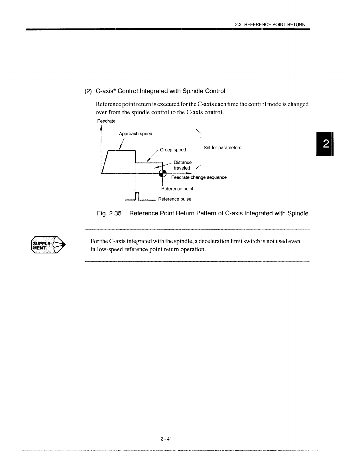
2.3 REFERENCEP OINTRETURN
(2) C-axis* Control integrated with Spindle Control
Reference point return is executed for the C-axis each time the control mode is changed
over from the spindle control to the C-axis control.
Feedrate
Approach speed
/
~ / creep “’’”
I
Reference point
-ii--
Fig. 2.35 Reference Point Return Pattern of C-axis lntegri~ted with Spindle
For the C-axis integrated with the spindle, a deceleration limit switch
in low-speed reference point return operation.
Reference pulse
Set for parameters
)
is not used even
Page 79
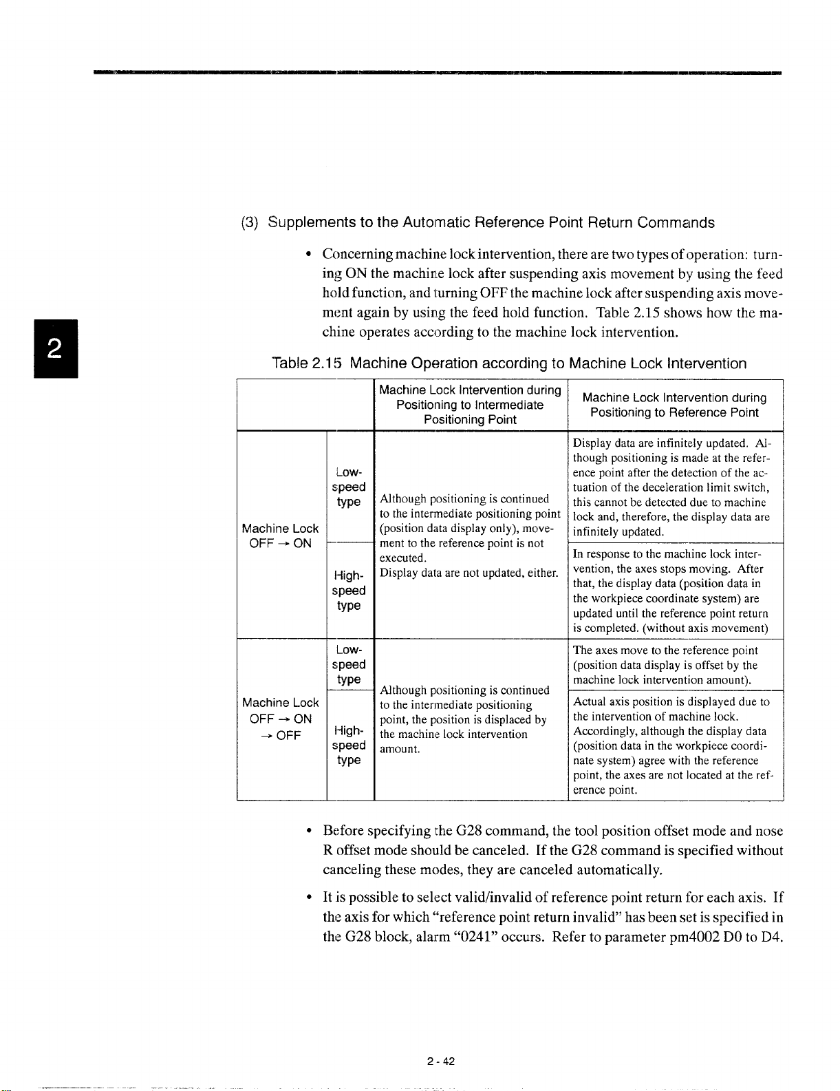
(3) Supplements to the Automatic Reference Point Return Commands
. Concerning machine lock intervention, there are two types of operation: turn-
ing ON the machine lock after suspending axis movement by using the feed
hold function, and turning OFF the machine lock after suspending axis movement again by using the feed hoid function. Table 2.15 shows how the machine operates according to the machine lock intervention.
Table 2.15 Machine Operation according to Machine Lock Intervention
Machine Lock
OFF + ON
Machine Lock
OFF - ON
- OFF
Low-
speed
type
l+igh-
speed
type
Low-
speed
type
High-
speed
type
kfachine Lock Intervention during
Positioning to Intermediate
Pcx3itioning Point
41though positioning is continued
.Othe intermediate positioning point
position data display only), movementto the reference point is not
jxecuted.
Display data are not updated, either.
41though positioning is continued
:0the intermediate positioning
Joint, the position is displaced by
.he machine lock intervention
lmount.
Machine Lock Intervention during
Positioning to Reference Point
Display data are infinitely updated. Although positioning is made at the reference point after the detection of the actuation of the deceleration limit switch,
this cannot be detected due to machine
lock and, therefore, the display data are
infinitely updated.
In response to the machine lock intervention, the axes stops moving. After
that, the display data (position data in
the workpiece coordinate system) are
updated until the reference point return
is completed. (withoot axis movement)
The axes move to the reference point
(position data display is offset by the
machine lock intervention amount).
Actual axis position is displayed due to
the intervention of machine lock.
Accordingly, although the display data
(position data in the workpiece coordinate system) agree with the reference
point, the axes are not located at the reference point.
● Before specifying I:heG28 command, the tool position offset mode and nose
R offset mode should be canceled. If the G28 command is specified without
canceling these modes, they are canceled automatically.
c It is possible to select valid/invalid of reference point return for each axis. If
the axis for which “reference point return invalid” has been set is specified in
the G28 block, alar-m “0241” occurs. Refer to parameter pm4002 DO to D4.
2-42
Page 80

2.3 REFERENCEPOINTRETURN
● Itispossible todisplay aliirm`<0411'' (>C-axis) to`` 0415''(5th-axis) when an
axis move command other than G28 is executed without completing reference
point return after turning ON the power. Whether or not such alarm display
should be given is determined by the setting for parameter pm4022. The direction of reference point return is set for pm4002 DO to D4 for the individual
axes.
● The absolute coordinate values of the axes specified in the G28block are saved
to memory as the intermediate positioning point. For the axes not specified
in the G28 block, the intermediate positioning point saved in the previous reference point return operation remains valid.
● If M and/or T command is specified with G28 in the same b .ock, the axes con-
tinue moving to the reference point disregarding whether or not the FIN processing is completed before the positioning of an axis at the intermediate positioning point. Therefore, DEN is output at the reference IIoint.
● The deceleration limit switch position must be carefully attended to when
executing the reference point return for the first time after turning ON the power. For details, refer to 2.4.2, “Manual Reference Point Return” of the Operating Manual.
——..- .... .. .. .. . ........ . . .. ____ . .-__, r._.._... ._. —
2-43
-.+..--—.—...—..-.....-.——
—,. -.-. —- ——, ——. -..
.- ..-. .—
Page 81

2.3.2 Reference Point Return Check (G27)
This function checks whether the axes are correctly returned to the reference point at the
completion of the part program which is created so that the program starts and ends at the
reference point in the machine by specifying the commands of “G27 X(U)” “ cZ(W)” “ o
(* C(H) .00
In the G27 mode, the function checks whether or not the axes positioned by the execution
of these commands in the simultaneous 2-axis (* 3-axis) control mode are located at the reference point. For the axes not specified in this block, positioning and check are not executed.
(1) Operation after the Check
When the position reached after the execution of the commands in the G27 block agrees
with the reference point, the reference point return complete lamp lights. The automatic
operation is continuously executed when all of the specified axes are positioned at the
reference point.
reference point return check: error (alarm “0421” (X-axis) to “0425” (5th-axis)) occurs
and the automatic operation is interrupted. In this case, the cycle start lamp goes OFF.
* Y(V “ “ “);”.
If there is an axis that has not been returned to the reference point,
(2) Supplements to the Reference Point Return Check Command and Other
Operations
● If G27 is specified in the tool position offset mode, positioning is made at the
position displaced by the offset amount and the positioning point does not
agree with the reference point. It is necessary to cancel the tool offset mode
before specifying (327. Note that the tool position offset function is not canceled by the G27 command.
● The reference point return check is not executed if G27 is executed in the ma-
chine lock ON state.
c The mirror image function is valid to the direction of axis movement in the
reference point return operation called by G27. To avoid a position unmatch
error, the mirror image function should be canceled by specif ying G69 (mirror
image OFF) before executing G27.
2-44
Page 82
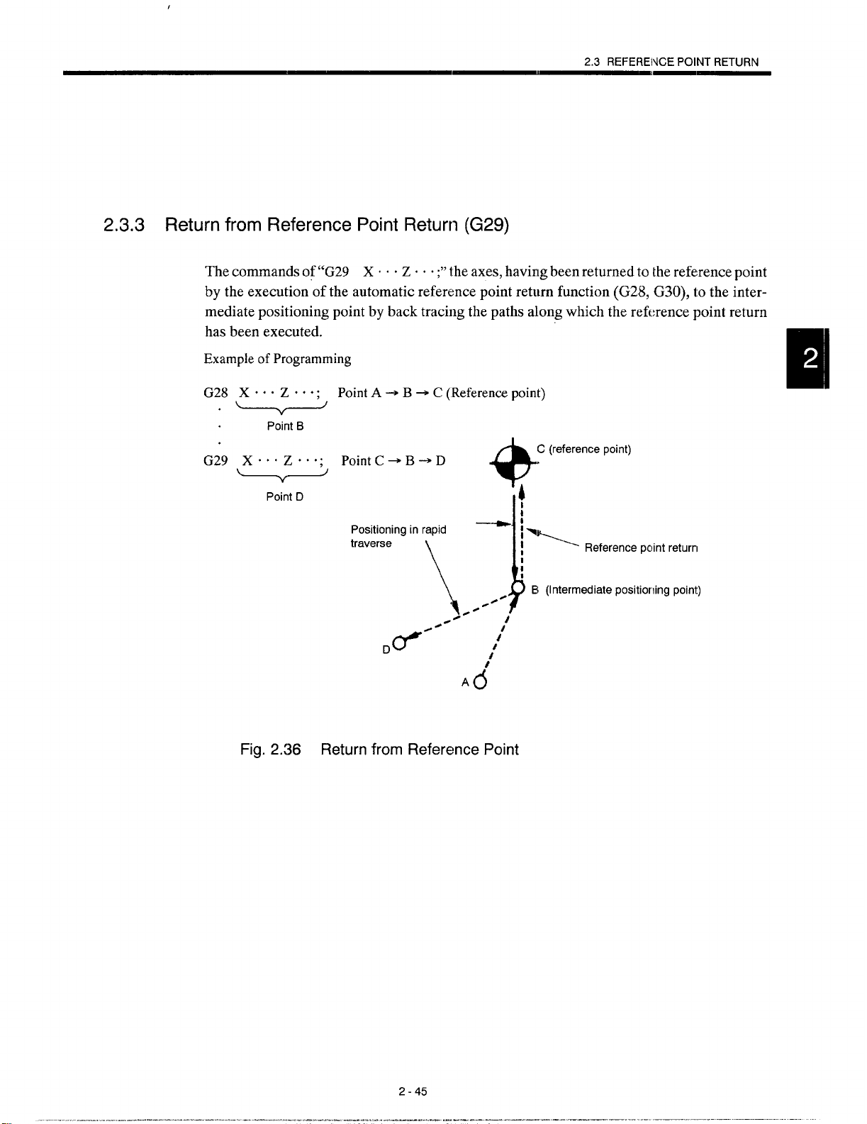
I
2.3.3 Return from Reference Point Return (G29)
The commands of “G29 X ““. Z .0. ;“ ihe axes, having been returned to the reference point
by the execution of the automatic reference point return function (G28, G30), to the intermediate positioning point by back tracing the paths along which the reference point return
has been executed.
Example of Programming
2.3 REFERENCE POINT RETURN
G28 XOO” Z” O”;
“~
PointB
G29
Point A ~ B - C (Reference point)
Point C+B~D
u
Point D
Positioning in rapid
traverse
\)
.&””-
Fig. 2.36 Return from Reference Point
@-
~
~!=
‘).=O.
A
v
I
I
i
*
C (reference point)
Reference pclint returrl
B (Intermediate positioning point)
Page 83

(1) Intermediate Positioning Point
● It is not possible to specify the intermediate positioning point in the G29 block.
The axes return to the previous point at a rapid traverse rate along the paths
taken in the return to the reference point. Note that the axes not specified in
the G29 block do not move.
● If G28 or G30 (see :2.2.4, “Second to Fourth Reference Point Return (G30)*”)
has been executed several times before the execution of G29, point B to be set
for the execution of B29 is established at the intermediate positioning point set
in the last G28 or Gr30 operation. The following program written in absolute
commands explains how point B is set for the return operation from the reference point.
Coordinate values of intermediate positioning point
Xz
N20
N23
N24
GOO
X30.Z20.;
X-40.Z-50.;
GOO
G28 Zlo. Z20. (lo., 20.)
G28 X30. ;
G29
X-4C). Z-50. ;
(30., 20.)
‘~ ~n~point
Intermediate positioning point
T
End point
2-46
Page 84

Example of Programming
N31 T0300;
N32 G28 U80. W20.;
N33 T0400;
N34 G29
U-80. W40.;
—1—1——
2.3 REFERENCEP OINTRETURN
(reference point)
Intermediate
(absolute coordinate values)
Fig. 2.37
● In the following cases, the intermediate positioning point used for the execu-
Coordinate Values c]f Point B for G29 Operation
tion of G29 does not agree with the intermediate positioning point specified
for the execution of G28 or G30. Therefore, do not specify such commands
or attempt such operation.
. Execution of the following before the execution of G29 after the comple-
tion of G28:
positioning point
+x
L
——-+Z
Coordinate system setting (G50 or coordinate system setting operation
in POS. job)
Intervention of machine lock
Intervention of manual operation with manual absohte OFF
o Execution of G28, or G30 or G29 in a block specified after the cancellation
of the mirror image at a position different from the position where the mirror image was started.
. Execution of G28, or M:30 or M29 after the intervention of manual opera-
tion with the manual absolute OFF.
Page 85

(2)
Supplements to the Return Command from the Reference Point Return
Automatic reference point return
(a)
If G29 is specified without the execution of G28 or G30 after turning ON the power,
alarm “0240” occurs.
Nose R offset and canned cycle
(b)
If G29 is specified in the nose R offset mode (G41, G42) or in a canned cycle (G70
to G76, G90, G92, G94, G81 to G89), alarm “0170” or “0182” occurs.
Tool position offset
(c)
It is necessary to cancel the tool position offset function before specifying G28,
G30, or G29. If these G codes are executed in the offset mode, the intermediate
positioning point B’ is also offset, causing the tool to move to point B. Note that
the tool position offset function is not canceled by G29.
C (reference point)
+
D’ ----4
b“
0
$“
Fig. 2.38 G29 Operation Executed
//
B’
,~ >~ ~’e’ ‘Ount
/
B (intermediate positioning point)
in the Tool Position Offset Mode
2-48
Page 86

——1
2.3.4 Second to Fourth Reference Point F~eturn(G30) *
With the commands of “G30 Pn X(U) I o“ Z(W) “ “ . (* C(H) “ “ oY(V) ..0 );”, the axes
are moved to P2 (second reference point), P3 (third reference point*), or P4 (fourth reference
point*) in the simultaneous 3-axis (* 5-axis) control mode after the positi oning at the specified intermediate positioning point. If “G30 P3 U-40. ‘W30.;” is specifiecl, the X- and Z-axis
return to the third reference point. If “Pn” is omitted, the second reference point is selected.
The axes not specified in the G30 block do not move.
Reference Point Positions
(1)
The position of each reference point is determined in reference to the first reference
point. The distance from the first reference point to each of the reference points is set
for the following parameters.
2,3 REFERENCE POINT RETURN
m
Table 2.16 Reference Points
X-axia Z-axis
2nd reference point
3rd reference point
4th referenee point
(2)
Supplements to the 2nd to 4th Reference Point Return Commands
● For the points to be considered to for the execution of G30, ~efer to the supple-
pm6811
pm6821 pm6822 pm6823
pm6831
pm6812 pm6813
pm6832 pm6833 pm6834 pm6835
3rd-axis
ments in 2.2.1, “Automatic Return to Reference Point (G2!8)”.
c If G29 is specified after G30, positioning is made at the point specified with
G29 after passing the intermediate positioning point specified with G30. Only
the coordinate value of intermediate positioning point of the axis specified
with G30 is updated,
● For the execution of G30, reference point return must have been completed
after power-ON either manually or by the execution of G28. If an axis for
which reference point return has not been completed is included in the axes
specified in the G30 block, alarm “0240” occurs.
4th axis
prn6B14
pmi5824
a
5th-axis
pm6815
pm6825
... —-...—_ ..—.__..._. .. . .. ...___. _______ ._
.—______ .
2-49
——— ...-—— ———------- ———. .. .,.- ——... —. —.—.—
,—-—...
Page 87

3
MOVEMENT CONTROL COMMANDS
Chapter 3 describes the procedure used for settilllg and selecting the coordinate system and the programming for con-
trolling the movement of a cutting tool.
3.1 SEl17NG THE COORDINATE
SYSTEM . . . . . . . . . . . . . . . . . . . . . . . . . ...3-3
3.1.1 Base Coordinate System (G50) . . . . . . . . . . . . 3-3
3.1.2 Workpiece Coordinate System
(G50T, G51)* . . . . . . . . . . . . . . . . . . . . . . . . . . . 3“7
3>2 DETERMINING THE COORDINATE
VALUE INPUT MODES . . . . . . . . . . . ...3- 16
3.2.1
3.2.2 Diametric and Radial Commands
3.2.3 Inch/Metric Input Designation (G20, G21!) , , 3-20
3.3 TIME-CONTROLLING COMMANDS , ..3-22
3.3.1
3.4 TOOL OFFSET FUNCTIONS . . . . . . . ..3-23
3,4.1 TooIOffeet Data Memory . . . . . . . . ,,, . . ...3-23
3.4.2
3.4.3 Nose R Offset Function (G40, G41/G42) * . . 3-29
Absolute/incremental Designation . . . . . , . . . 3-16
for X-axis . . . . . . . . . . . . . . . . . . . . . . . . . .,...3-19
Dwell (G04) . . . . . . . . . . . . . . . . . . . . . . . . . ...3-22
Tool Position Offset . . . . . . . . . . . . . . . . . . ...3-24
Page 88

3.5 SPINDLE FUNCTION (S FUNCTION) .3-75
3.5.1
3.5.2
3.5.3
3.5.4
Spindle Command (S5-digit Command) . . . . 3-75
Maximum Spindle Speed Command
(G50S) . . . . . . . . . . . . . . . . . . . . . . . . . . . . ...3-76
Constant Surface Speed Control
(G96, G97)* . . . . . . . . . . . . . . . . . . . . . . . . . . .3-77
I<otary Tool Spindle Selection Function * . . . 3-81
3.6 TOOL FUNCTION (T FUNCTION) . . ...3-82
3.6.1
3.6.2
T4-digit Command. . . . . . . . . . . . . . . . . . . ...3-82
‘r6-digit Command* . . . . . . . . . . . . . . . . . . ...3-82
3.7 MISCELLANEOUS FUNCTION
(M FUNCTION) . . . . . . . . . . . . . . . . . . ...3-83
3.7.1 ItiCodes Relating to Stop Operation
(MOO, MOI, M02, M30) . . . . . . . . . . . . . . . ...3-83
3.7.2
3.7.3
Internally Processed M Codes . . . . . . . . . . . . 3-84
General Purpose M Codes...,,. . . . . . . . . . 3-85
3-2
Page 89

3.1 SElllNG THE COORDINATE SYSTEMI
3.1.1 Base Coordinate System (G50)
Before programming axis movement, a coordinate system must be set. “Nhen a coordinate
system is set, a single absolute coordinate system is determined and absolute move commands specified after the setting of a coordinate system are all executed ill it. The G50 command sets the position of the origin of a coordinate system used for programming.
G50 is a non-modal G code that is valid (only in the specified block. The block in which the
G50 command is specified must not contain other G codes, M codes, S codes, and T codes.
Especially, if an S or T code is specified in a block with G50- like “G50 S” o “;“ or
“G50T “ “ “
(1)
;“, such designation calls specific functions and does not set a coordinate system.
Commands
3.1 SEITING THE CCIORDINAT’E SYSTEM
For setting a coordinate system, both absolute and incremental comnlands may be used.
Coordinate system setting in absolute commands
(a)
With the commands of “G50 X. 0.0 Z “ “ “
(“c... *Y”. “) ;“, a coordinate system is set so that the present tool nose position has the absolute coordinate values
specified in the G50 block (X, Z, C, B*, Y *). In other words, the addresses in the
G50 block specify the distance from the point that should be set as the origin (O,
O,O)of the coordinate system used for progmmming to the present tool nose position. Axis movement commands can be specified for up to 2 aces (* 5 axes max.)
simultaneous y. Note that the axes not specified the G50 block do not move.
An example of coordinate system setting is shown in Fig. 3.1. In this example, the
coordinate system is set at the position where reference poilnt return has been
executed. A coordinate system can be set at any position.
Present tool nose
+x
position
1.1
z
coordinate system
A
*
+2
Fig. 3.1
Setting of Base Cc)ordinate System (G50) at Reference Return
Position
3-3
—.. ——-. ——___. ——.. —......- .—.— .—.. -.. -———-—— --
Page 90

Coordinate system setting in incremental commands
(b)
If addresses U, W, and IHare specified with the commands of “G50 X “ .0 Z o c .
(* H... *VCO
o) ;“, a new coordinate system is set in reference to the present
coordinate system by shifting it the distance specified in incremental values of U
(X-axis direction), W (Z-axis direction), and H (C-axis direction).
This feature is effectively used in several applications - an operation that uses cutting tools having considerable differences, for example. In this case, the cutting
tools should first be divided into two groups and the difference between the length
of standard tool in one group and that in the other group should be entered in a program. Then, a new base coordinate system can be set for the second tool group.
Example of programming
G50 U1OO. W- 100.;
Fig. 3,2
(2)
Coordinate System and 100 I Position Offset
Setting of Coordinate System with Incremental Values
‘fpo.itiono~%’i’h5:’didtool
-+,
After setting the coordinate system by executing the commands of “G50 X80. Z62.;”
taking the cutting tool No. 0“1,if the cutting tool No. 02 which has the tool position offset amount as shown in Fig. 3.3 is selected and offset is executed, the cutting tool No,
02 moves to point A.
Example of Programming
N3 G50 X80. Z62.;
N4 GOO TO1O1;
●
●
●
N1O GOOT0202;
●
●
●
‘+ti~o’’oo’
G50 comma;d
with No. 02 tool
selected
= 40 mm
$
Fig. 3.3
Coordinate System and Tool Position Offset
As shown in Fig. 3.3, if the coordinate system is set in reference to the standard tool
and offset data are set for other tools, it is possible to program all tool movements in
a single coordinate system.
3-4
Page 91

\\ I/,
POINT
3.1 SEITING THE CCIORDINATE SYSTEM
Automatic Coordinate System Setting
(3)
It is possible to set a coordinate system automatically at the completion of manual reference point return. To set the coordinate system in this manner, the sel:ting values should
be set for parameters for each of mm and inch input operation as irndicated below.
Table 3.1 Parameters for “mm” Input and “inch” Input
3. Whether or not the automatic coordinate system setting functio:n is made valid
or not should be set for parameters pm4006 DO to D4 for the individual axes.
Q
4. To use the workpiece coordinate system shift function, set the cocn-dinate system
by adding the workpiece coordinate system shift values to the coordinate system
setting values when setting the coordinates ystem using the autom atic coordinate
system setting function.
5. The coordinate system that has been set using the automatic coordinate system
setting function becomes invalid when other coordinate system setting function
such as G50 is executed.
.—. — —-- -—.——. — .——
3-5
.-. __, — .-_ —... _______ .—_—
.——.-——— ..- ,— ._-. _______
Page 92
(4) Supplements to the Base Coordinate System Commands
. If a T code is specified in the block next to the one in which the G50 command
is specified, it is necessary to enter GOOin the block where the T code is specified to define the offset movement feedrate.
G50Xoo” Zo -.;
GOO S500 M03 TO1O1;
● Cancel the tool position offset and nose R offset function before specifying
G50.
● When the power is turned ON, coordinate values (O,O,O)is set for the present
tool position. Therefore, the coordinate system must always be set before
starting an operation. Concerning the C-axis integral with the spindle, use the
automatic coordinate system setting function - change the mode to the C-axis
control and execute the reference point return, and the coordinate system is set
for the C-axis at the position where the reference point return has been completed.
● Once the coordinate system is set, it is not influenced by the reset operation.
To reset the coordinate system, use either of the following operation.
“ To set “O” on the [ABS] function screen.
“ To set “O”for the coordinate values by executing “G50 XO ZO(CO);” in the
MDI mode.
“ To turn OFF the power once and turn it ON again.
o The present tool position in the base coordinate system is displayed on the
[AIM] function name which is called in the [POSIT.] job.
● Whether or not the workpiece coordinate shift is valid when G50 is specified
is determined by the setting for parameter pm4012 DO.
3-6
Page 93
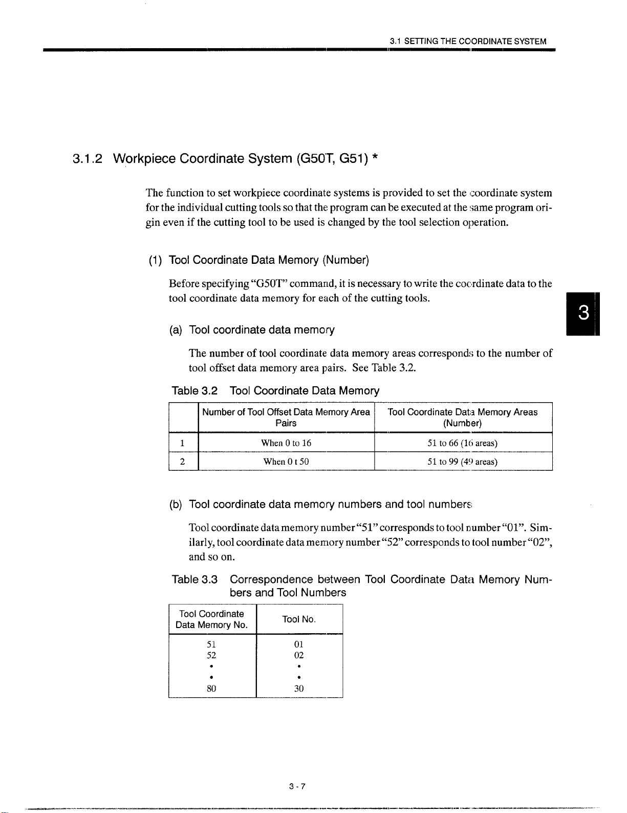
3.1.2 Workpiece Coordinate System (GsOT, Gsl ) *
The function to set workpiece coordinate systems is provided to set the coordinate system
for the individual cutting tools so that the program can be executed at the :same program origin even if the cutting tool to be used is changed by the tool selection operation.
(1) Tool Coordinate Data Memory (Number)
Before specifying “GSOT” commarid, it is necessary to write the cocxdinate data to the
tool coordinate data memory for each of the cutting tools.
(a) Tool coordinate data memory
3.1 SETrlNG THE CCIORDINATE SYSTEM
The number of tool coordinate data memory areas corresponds to the number of
tool offset data memory area pairs. See Table 3.2.
Table 3.2 Tool Coordinate Data Memory
Number of Tool Offset Data Memory Area
I
1
2
Tool coordinate data memory numbers and tool numbers
(b)
Pairs
When Oto 16
When Ot 50
+
Tool Coordinate
Ddi~ Memory Areas
(Number)
51 to 66 (I6 areas)
51 to 99 (4!)areas)
---i
Tool coordinate data memory number “51” corresponds to tool rmmber’’Ol”. Sim-
ilarl y, tool coordinate data memory number” 52” corresponds to tool number “02”,
and so on.
Table 3.3 Correspondence between Tool Coordinate Dat:~ Memory Num-
bers and Tool Numbers
Tool Coordinate
Memory No.
Data
51
52
.
Tool No,
01
02
.
I
3-7
3;
:
8;
Page 94

(c) Coordinate data: Xtn, Ztn
The coordinate data (Xtn, Ztn) as shown in Fig. 3.4 are written to the tool coordinate data memory for the individual tools Tn.
‘X*H
I
Ae-
Zm
f >
Xm
(L 7, i 4
The workpiece coordinate system determined
by the operator at the workpiece measurement
value direct input operation.
Fig. 3.4 Tool Coordinate Data Memory
/’
At,,
1
Workpiece
The tool post or turret is at the position
where the CNC’S present position data
display is (O,0).
1
‘xtn/2
+Z
3-8
Page 95
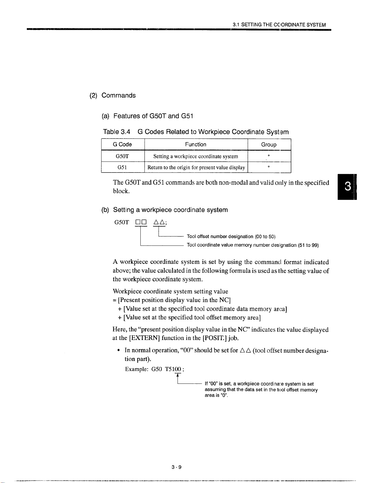
3.1 SEITING THE CCIORDINATE SYSTEM
(2) Commands
(a) Features of G50T and G51
Table 3.4 G Codes Related to Workpiece Coordinate Systsm
Setting a workplece coordinate system
=“’0”” %+
The G50T and G51 commands are both non-modal and valid o]dy in the specified
block.
(b) Setting a workpiece coordinate system
G50T ❑ 0 AA;
A workpiece coordinate system is set by using the comrnaml format indicated
above; the value calculated in the following formula is used as the setting value of
the workpiece coordinate system.
Workpiece coordinate system setting value
= [Present position display value in the NC]
+ [Value set at the specified tool coordinate data memory area]
+ [Value set at the specified tool offset memory area]
Here, the “present position display value in the NC” indicates t~llevalue displayed
at the [EXTERN] function in the [POSIT.] job.
Return to the origin for present value display
TT
~ Toed offset number designation (00 to 50)
Toc,l coordinate value memory number designation (51 to 99)
———-. ... ———. ——
● In normal operation, “00” should be set for A A (tool offset number designa-
tion part).
Example: G50 T51OO ;
T
3-9
..— ..——.. -—.. . .. . ......... . . ... -— ——— —.. —.,—..
If “00” is set, a workpiece coordinae system is set
assuming that the data set in the tool offset memory
area is “0.
.- ,—— —.. —.—
-—.
Page 96

When the program as indicated in the example above is set when the tool post
or turret is positioned at arbitrary position, the workpiece coordinate system
that the operator has determined is set correctly.
T1 when the turret or tool post is positioned
at an arbitrary position (-x, -z)
+x
)
z~l
T1
\
{ \ #
(L \
Workpiece coordinate system
Fig. 3.5
● With the commands of “G50 TOOOO;”,the workpiece coordinate system is
Workpiece Coordinate System Setting
I
-z
/
(-x/2) +x!, /2
(-z) +z~,
When the turret or tool post
is positioned at (O,O)
- +Z
The workpiece coordinate
is set using these values.
}
canceled. That is, the command TOOOOcauses the calculation of the present
position data with “value in tool coordinate data memory = O“ and “value in
tool offset data memory = O“ to set the workpiece coordinate system.
Returning to the origin for present position (G51 )
(c)
system
With arnachiningprograrn that uses the workpiece coordinate system setting function, the start point of machining should be set at the position where the present
position data display is (,0,O). Therefore, after the completion of machining, G51
must be specified in the program so that the X- and Z-axis return to the start point
of machining accurately. With theG51 command, both of the X- and Z-axis return
to the start point at a rapid traverse. Note that G51 should be specified in a block
independently without other commands.
3-1o
Page 97

3.1 SElllNG THE COORDINATE SYSTEM
(3) Example of Programs
(a) Example program using a workpiece coordinate system
An example of program in which a workpiece coordinate systl>m is used is given
below.
The start point of machining is (O,O) of present position display.
N1 G50 T51OO; ~
N2 GOOTO1O1 M03 S1OO; ~
(Machining using tool No. 01)
Setting of a workpiece coordinate system for
tool No. 01
Selection of tool No. 01 (Note)
N20
GOOXC”” ZO”” -
N21
G50 T5200; _
N22
GOO T0202; —
Positioning
Setting of a workpiece coordinate system for
tool No. 02
Selection of tool No. 02 (Note)
(Machining using tool No. 02)
N40
G51; c
+x
T02
Returning to the point of (O,O) (present position
data display)
\
Position where position
data display is (O,O)
N20
+Z
Workpiece coordinate system
(Machining with tool NCE. 01 and 02 is programmed in this coordinate system)
Note: The tool position offset command in TOIC1 and T0202 can be used for the compensaticln for tool wear. [t can also
be used for offsetting in taper cutting.
Fig. 3.6 Example Program Using Workpiece Coordinate Systelm
3-11
Page 98

(b) Example of program in which operation in a workpiece coordinate system
is interrupted
If an operation is restarted from the beginning of the program without returning the
cutting tool to the start point of machining after the interruption of the program given below, the cutting tool is positioned correctly at the first approach position.
Example of program in which operation in a workpiece coordinate system is interrupted
N1 G50 T51OO;
N2 TO1O1;
N3 G96 S150 M03;
N4 GOO X20. Z2.5;
+x
/,
When the operation is restarted from the position
of (-20., -27.5) after the interruption
/
+-A
B
Workpiec~ coordinate
system
A Approach position (20., 2.5)
(TooI coordinate data memory 51X= 80.
Machining start position
= Present position data display (O,O)
+Z
51Z = 40.)
Fig. 3.7 Example of program in which operation in a workpiece coordinate
system is interrupted
The commands of “N1 (350 T51OO;” executed at point B sets a workpiece coordinate system using the values of X = 60. (-20. + 80.) and Z = 12.5 (-27.5 + 40.).
Therefore, the workpiece coordinate system is saved and, accordingly, the approach position point A remains unchanged.
Page 99

3.1 SEITING THE COORDINATE SYSTEM
(c) If tool change positions differ in a workpiece coordinate :system
An example of program and workpiece coordinates ystem setti ng values are indicated below for cases where tool change position differs by tclols.
Table 3,5 Tool Coordinate Data Memory
-:
N1 G50 T51OO;
N2 GOOTO1O1 M03 S1OOO;
“ (Machining with TO1)
N25 G50 TOOOO;
N26 GOOX-50. Z-35.;
N27 G50 T5200;
N28 GOO T0202 M03 S800;
. The coordinate system setting values used
“ (Machining with T02)
N48 G51;
+x
1
z = 5“ T02
# 0100.
‘z
~. \--
F
$110.
47,5 Tol
J’f’
TO1
— Tool changepositionto
by these commands are:
X= (-50.) + 110. =60.
z = (-35.) + 40. = 5,
T02
/
Machining start position
= Position where present position clata is (O,O)
i.-
-50./2
-35. -
T02 is (-50,, -35.).
P
X = 4J60.
+ +Z
Workpiece coordinate system
Fig. 3.8 If Tool Change Positions Differ in a Workpiece Coordinate System
Page 100

(4) Workpiece Coordinate System Shift Amount
The coordinate system that is set using G50 or the workpiece coordinate system setting
function can be shifted by the required distance. It is possible to write the shift distance
to the workpiece coordinate system shift data memory, which is No. 00 of the offset data
memory data, for the X-, Z- and C-axis in the same operation as writing the tool offset
data.
(a) Shift data written to the memory
The shift data written to the memory becomes valid at the following timing:
● Execution of the G50 coordinate system setting command
. Execution of the G50 T workpiece coordinate system setting command
Q Execution of the automatic coordinate system setting function
● Execution of key operation for setting the coordinate system.
When any of the operation indicated above is executed, a coordinate system is set
by simply adding the set shift amount. No cutting tool movement takes place. If
a positive value is set for AX, AZ, and AC, the coordinate system is shifted in
the direction indicated by the arrow symbol in Fig. 3.9. In this figure, ~ and Z.
indicate the original coordinate system setting values.
+x +x
-tz ~
XO12
~m-
Shift
4
t AX/2
I
Originel coordinate system
/
+Z
+.p.+z
Coordinate system set after the shift
Fig. 3.9 Workpiece Coordinate System Shift Operation
The direction in which the coordinate system should be shifted can be changed by
changing the setting fclr parameter pm4012 D3. By setting DO, it is possible to
make the shift amount invalid at the execution of G50.
 Loading...