

Page 1
<
D
c)
in
0
Z
z
D
z
0
m
D
l-
-l
<
-0
m
v,
?
D
Page 2
Safety lnfor
The following conventions are used to indicate precautions in this manual. Failure to heed the precautions provided in this manual can result in serious or possibly even fatal injury or damage to the products or related equipment and systems.
/A WARNING /
Indicates a potentially hazardous situation which, if not avoided, could result in death or seri-
ous injury to personnel.
-mati In
Symbol
is used in labels attached to the product.
IA CAUTION 1
Indicates a potentially hazardous situation which, if not avoided, may result in minor or mod-
erate injury to personnel and damage to equipment.
Even items described in
case, follow these important items.
A CAUTION
may result in a vital accident in some situations. In either
iii
Page 3
Visual Aids
The following aids are used to indicate certain types of information for easier reference.
Indicates important information that should be memorized, including precautions such as alarm displays to avoid damaging the devices.
Indicates supplemental information.
Indicates definitions of difficult terms or terms that have not been previously explained in this manual.
0 Yaskawa, 1998
All rights reserved. No part of this publication may be produced, stored in a retrieval system, or transmitted, in any form, or
by any means, mechanical, electronic, photocopying, recording, or otherwise, without the prior written permission of Yaskawa. No patent liability is assumed with respect to the use of information contained herein. Moreover, because Yaskawa is
constantly strivin,o to improve its high-quality products, the information contained in this manual is subject to change without notice. Every precaution has been taken in the preparation of this manual. Nevertheless, Yaskawa assumes no responsibility for errors or omissions. Neither is any liability assumed for damages resulting from the use of information contained
in this publication.
Page 4
CONTENTS
Safety Information
...............................................
VisualAids .....................................................
About this Manual
Related Manuals
Notes for Safe Operation
...............................................
................................................
.........................................
1 GENERALS . . . . . . . . . . . . . . . . . . . . . . . . . . . . . . . . . . . . . . . .
1.1 CONFIGURATION
1.1.1 System Configuration
1.1.2
1.1.3 ConnectorLayout
ConnectionbetweenDevices.. .......................................
1.2 GENERAL SPECIFICATIONS . . . . . . . . . . . . . . . . . . . . . . . . . . . . . . .
1.3 DESIGNOFBOX
1.3.1 ThermalDesign ....................................................
1.3.2 Dustproof Design
1.3.3 Countermeasures against Magnetic Fields
1.4 CABLE CLAMP AND SHIELDING
1.5 PACKAGING ..............................................
1.5.1 GeneralNotes
1.5.2
1.53 Installation of Servo Unit
Installation of CNC Unit
.........................................
................................................
...................................................
..........................................
................................................... 1 - 11
.............................
............................
......................................................
..............................................
.................. :.
.........................
iii
iv
ix
ix
X
l-l
l-2
l-2
l-3
l-4
1 - 5
l-6
l-6
l-13
1 - 14
l-15
l-15
l-16
l-17
2 CONNECTION OF POWER SUPPLY . . . . . . . . . . . . . . . . . .
2.1 CONNECTION BETWEEN DEVICES
2.1.1 Power Supply to CNC Unit
2.1.2 Power Supply to Converter Unit
2.2 DETAILED CONNECTION
2.2.1 PowerSupplytoCNCUnit
2.2.2 Power Supply to Converter Unit
........................................... 2-2
....................................... 2-2
...................
........................................... 2-3
.......................................
.........................
:
..............
3 CONNECTION OF CNC OPERATION PANEL . . . . . . . . . .
3.1 CONNECTION BETWEEN DEVICES
3.1.1 Connection with g-inch CRT Operation Panel ...........................
3.2 DETAILED CONNECTION OF CNC OPERATION PANEL
3.2.1
3.2.2 General Notes on the Connenction of CRT Operation Panel
Connection with g-inch CRT Operation Panel .......................
.........................
....... 3 - 3
:.
..............
..
2 - 1
2 - 2
2-3
2 . 3
3 - 1
3 - 2
3 - 2
3-3
3-4
Page 5
4 CONNECTION OF MANUAL PULSE GENERATOR . . . . . . 4 - 1
4.1 CONNECTION BETWEEN DEVICES
4.1.1 Connection with g-inch CRT Operation Panel
......................... 4 - 2
........................... 4 - 2
4.2 DETAILED CONNECTION OF MANUAL PULSE GENERATOR . .
4.2.1 Non-parallelI/F..................................................... 4-3
4.2.2
ParallelI/F . . . . . . . . . . . . . . . . . . . . . . . . . . . . . . . . . . . . . . . . . . . . . . . . . . . . . . . . .
5 CONNECTION OF POWER ON/OFF
EXCLUSIVE SIGNAL . . . . . . . . . . . . . . . . . . . . . . . . . . . . . . . . .
5.1 CONNECTION BETWEEN DEVICES . . . . . . . . . . . . . . . . . . . . . . . . .
5.1.1
5.2 DETAILED CONNECTION OF POWER ON/OFF
5.2.1 Connection to CNC Unit . . . . . . . . . . . . . . . . . . . . . . . . . . . . . . . . . . . . . . . . . . . . .
5.3 DETAILS OF SIGNAL ......................................
5.3.1
5.3.2 Emergency Stop (‘ESP) Input ........................................
5.3.3
Connection to CNC Unit . . . . . . . . . . . . . . . . . . . . . . . . . . . . . . . . . . . . . . . . . . . . . 5-2
EXCLUSIVE SIGNAL . . . . . . . . . . . . . . . . . . . . . . . . . . . . . . . . . . . . . . .
Servo Power ON (SVMX), Brake Release (BKX) Output
External Power ON/OFF (EON, EOF, ECOM) Input
.................. 5 - 4
...................... 5-5
4 - 3
4-4
5-l
5 - 2
5 - 3
5-3
5 - 4
5 - 5
6 CONNECTION OF FEED SERVO UNIT . . . . . . . . . . . . . . . .
6.1 CONNECTION BETWEEN DEVICES
6.1.1 Connection with l-axis Servo Unit ....................................
6.1.2 Connection with 3-axis Servo Unit ....................................
6.2 DETAILED CONNECTION WITH FEED SERVO UNIT . . . . . . . . . .
6.2.1 No.1 Axis .................
6.2.2 No.2 Axis .................
6.2.3
6.2.4 No.4 Axis .................
6.2.5
6.2.6
No.3 Axis .................
No.5 Axis .................
IR Type Servo Unit .........
. .
6.3 DETAILED CONNECTION OF SERVO UNIT MAIN CIRCUIT . . . .
6.3.1
6.3.2 Connection with 3-axis Servo Unit . . . . . . . . . . . . . . . . . . . . . . . . . . . . . . . . . . . .
Connection with l-axis Servo Unit . . . . . . . . . . . . . . . . . . . . . . . . . . . . . . . . . . . .
6.4 USEOFSERVOUNIT.. ....................................
6.4.1
6.4.2 Protection of Power Line .............................................
Noise Suppression ..................................................
vi
......................... 6 - 2
. . . .
. . . .
. . . .
. . . .
. . . .
. . . .
. . . .
. . . .
. . . .
. . . . . . . . . .
6 - 1
6-2
6 . 4
6-6
6-6
6-6
6-7
6-7
6-8
6-8
6 - 10
6-10
6- 11
6-12
6-12
6-16
Page 6
7 CONNECTION OF SPINDLE DRIVE UNIT
.............
7-l
7.1 CONNECTION BETWEEN DEVICES .........................
7.1.1 Pulse Generator with Built-in Motor
7.1.2
7.1.3 Main Circuit, Converter, and
Separate Spindle Pulse Generator
lnverter
...................................
....................................
...................................
7.2 DETAILED CONNECTION WITH SPINDLE DRIVE UNIT .......
7.2.1
7.2.2 Separate Spindle Pulse Generator
7.2.3 Main Circuit, Converter, and
8 CONNECTION OF TAPE READER
Pulse Generator with Built-in Motor
lnverter
...................................
....................................
..........................
....................
8.1 CONNECTION BETWEEN DEVICES .........................
8.1.1 Connection with CNC Unit
...........................................
8.2 DETAILED CONNECTION OF TAPE READER ................
8.2.1
MODEL2801E
9 CONNECTION OF RS-232C
.....................................................
.........................
9.1 CONNECTION BETWEEN DEVICES .........................
9.1.1 Connection with CNC Operation Panel
.................................
.........
7-2
7-2
7-2
7-3
7-4
7-4
7-5
7-6
8-1
8-2
8-2
8-3
8-3
9-l
9-2
9-2
9.2 DETAILED CONNECTION OF RS-232C ......................
9.2.1 Connection with CNC Operation Panel
9.3 RS-232C INTERFACE
9.3.1
9.3.2
9.3.3
9.3.4 Cable Length
9.3.5 Connection between Devices
9.3.6
TransmissionMethod
CodestobeUsed
Communication Baud Rate
.......................................................
Signal Communication Timing
.....................................
................................................
...................................................
...........................................
.........................................
........................................
10 CONNECTION OF DIRECT-IN
10.1 CONNECTION BETWEEN DEVICES
10.1.1 Connection to CNC Unit
10.2 DETAILED CONNECTION OF DIRECT-IN
10.2.1 Connection to CNC Unit
.............................................
.............................................
vii
.................................
.......................
.........................
....................
9-3
9-3
9-4
9-4
9-4
9-5
9-5
9-5
9-7
10 - 1
.
10 2
10-2
.
10 3
10-3
Page 7
10.3 DESCRIPTION OF SIGNAL
10.3.1 Input Circuit on CNC Side
............................................
.................................
10 - 4
10-4
11 CONNECTION OF I/O MODULE . . . . . . . . . . . . . . . . . . . . . . 11 - 1
11.1 CONNECTION BETWEEN DEVICES.. . . . . . . . . . . . . . . . . . . . . . . .
11 .l .l Connection between Units
. . . . . . . . . . . . . . . . . . . . . . . . . . . . . . . . . . . . . . . . . . .
11.2 DETAILED CONNECTION OF I/O MODULE . . . . . . . . . . . . . . . . . .
11.2.1 Connection between Units
. . . . . . . . . . . . . . . . . . . . . . . . . . . . . . . . . . . . . . . . . . . 11 -3
11 - 2
11 -2
11 - 3
11.3 CONNECTION BETWEEN DEVICES OF
ADDITIONAL I/O MODULE
11.3.1 Connection between Units . . . . . . . . . . . . . . . . . . . . . . . . . . . . . . . . . . . . . . . . . .
. . . . . . . . . . . . . . . . . . . . . . . . . . . . . . . . .
11.4 DETAILED CONNECTION OF ADDITIONAL I/O MODULE . . . . . .
11.4.1 Connection between Units
. . . . . . . . . . . . . . . . . . . . . . . . . . . . . . . . . . . . . . . . . . . 11 -5
11 - 4
11 -4
11 - 5
12 CONNECTION OF GENERAL-PURPOSE l/O . . . . . . . . . . 12 - 1
12.1 CONNECTION BETWEEN DEVICES
12.1 .l Connection of Signal Line with I/O Module
.........................
.............................. 12-2
12.2 DETAILED CONNECTION OF GENERAL-PURPOSE I/O
12.2.1 FC81O/FC860 Module
12.2.2 FC861 Module
12.2.3 JSP02 Module
......................................................
...............................................
.....................................................
.......
12 - 2
12 - 4
12-4
12 - 20
12 - 29
12.3 DESCRIPTION OF GENERAL-PURPOSE I/O SIGNAL
12.3.1 I/OPort ............................................................
12.3.2 I/O Circuit of I/O Port
12.3.3 Power Supply for I/O Signal
................................................
..........................................
.........
12 - 38
12-38
12 - 42
12 - 50
Page 8
About this Manua
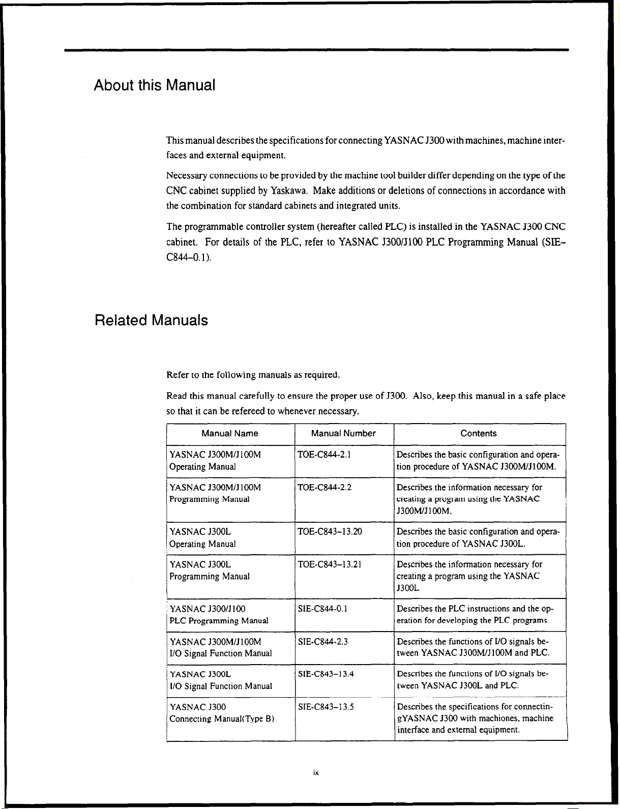
This manual describes the specifications for connecting YASNAC J300 with machines, machine interfaces and external equipment.
Necessary connections to be provided by the machine tool builder differ depending on the type of the
CNC cabinet supplied by Yaskawa. Make additions or deletions of connections in accordance with
the combination for standard cabinets and integrated units.
The programmable controller system (hereafter called PLC) is installed in the YASNAC J300 CNC
cabinet. For details of the PLC, refer to YASNAC J300/3100 PLC Progamming Manual (SlEC844-0.1).
.I
Related Manuals
Refer to the following manuals as required.
Read this manual carefully to ensure the proper use of J300. Also, keep this manual in a safe place
so that it can be refereed to whenever necessary.
Manual Name
YASNAC J3OOM/J IOOM
Operating Manual
YASNAC J3OOM/J IOOM
Programming Manual
YASNAC J3OOL
Operating Manual
YASNAC J3OOL
Programming Manual
YASNAC J3OO/J 100
PLC Programming Manual
YASNAC J300M/J 1 OOM
110 Signai Function Manual
YASNAC J3OOL
l/O Signal Function Manual
Manual Number
TOE-C844-2. I
TOE-C844-2.2
TOE-C843-13.20
TOE-C843-13.21
SIE-C844-0.1 Describes the PLC instructions and the op-
SIE-C844-2.3
SIE-C843-13.4
Describes the basic configuration and operation procedure of YASNAC J3OOM/JlOOM.
Describes the information necessary for
creating a program using the YASNAC
J3OOM/JlOOM.
Describes the basic configuration and operation procedure of YASNAC J3OOL.
Describes the information necessary for
creating a program using the YASNAC
J3OOL
eration for developing the PLC programs.
Describes the functions of UO signals be-
tween YASNAC J3OOM/J 1 OOM and PLC.
Describes the functions of l/O signals be-
tween YASNAC J3OOL and PLC.
Contents
YASNAC J300
Connecting Manual(Type B)
SIE-C843-13.5
ix
Describes the specifications for connectin-
gYASNAC
interface and external equipment.
5300 with machiones, machine
Page 9
Notes for Safe Operation
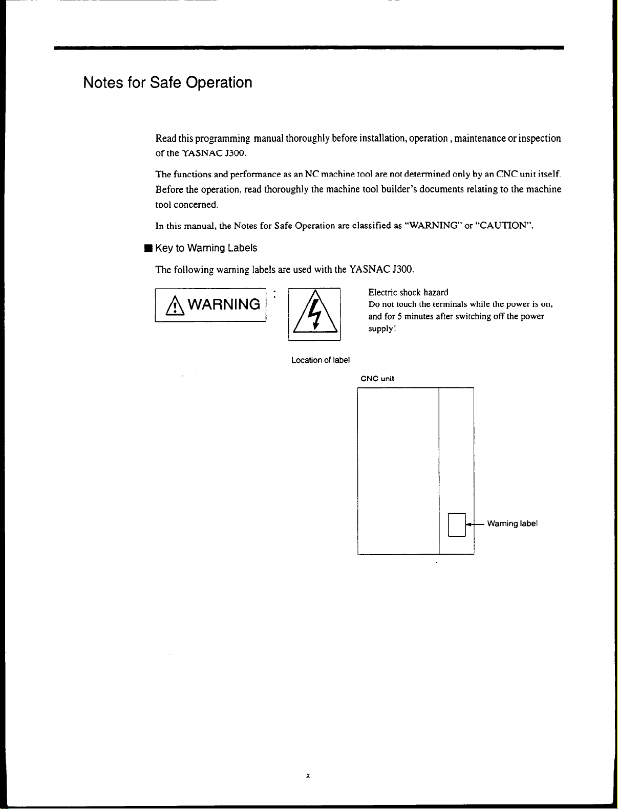
Read this programming manual thoroughly before installation, operation , maintenance or inspection
of the YASNAC 5300.
The functions and performance as an NC machine tool are not determined only by an CNC unit itself.
Before the operation, read thoroughly the machine tool builder’s documents relating to the machine
tool concerned.
In this manual, the Notes for Safe Operation are classified as “WARNING” or “CAUTION”.
W Key to Warning Labels
The following warning labels are used with the YASNAC 5300.
Location of label
CNC unit
-
cl-
Warning label
Page 10
VI ’ ml
Location of label
1
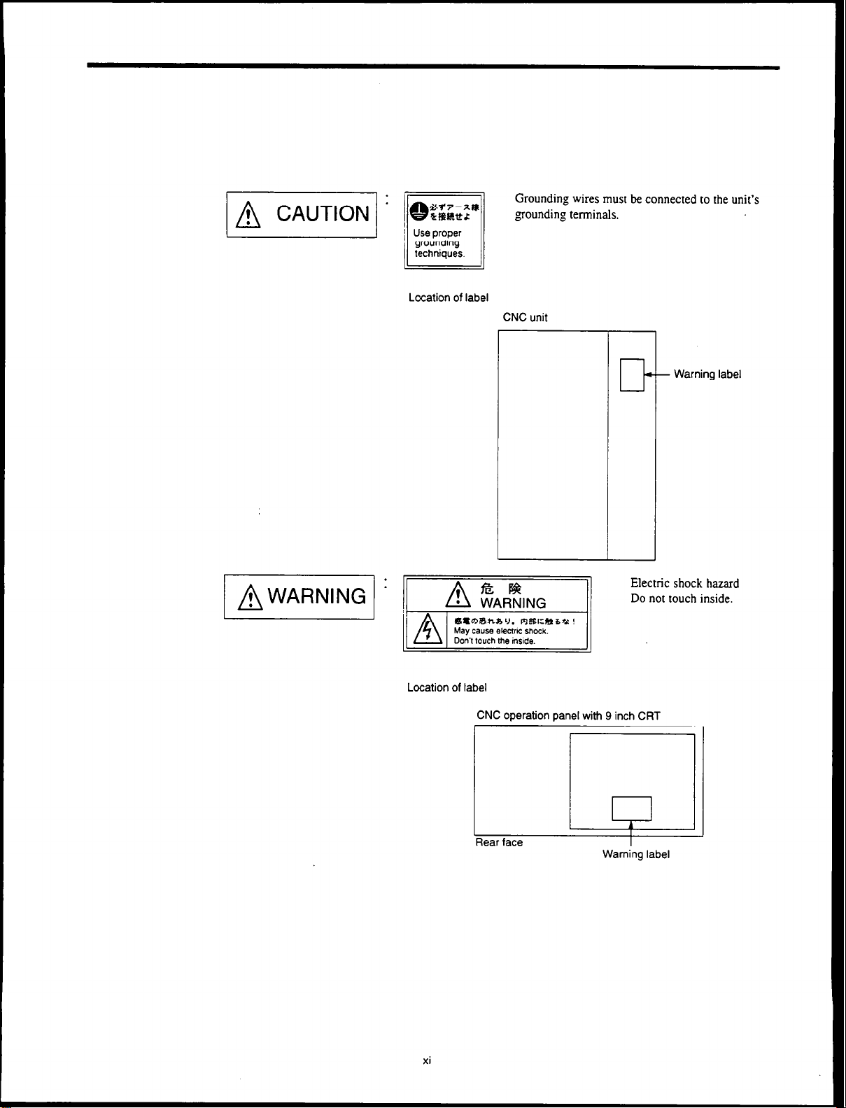
AWARNING 1
Grounding wires must be connected to the unit’s
goundin,o tet-tea
CNC
unit
-
+ Warning label
II-
Electric shock hazard
Do not touch inside.
Location of label
CNC operation panel with 9 inch CRT
I
,
Rear face
xi
I
I
Warning label
Page 11
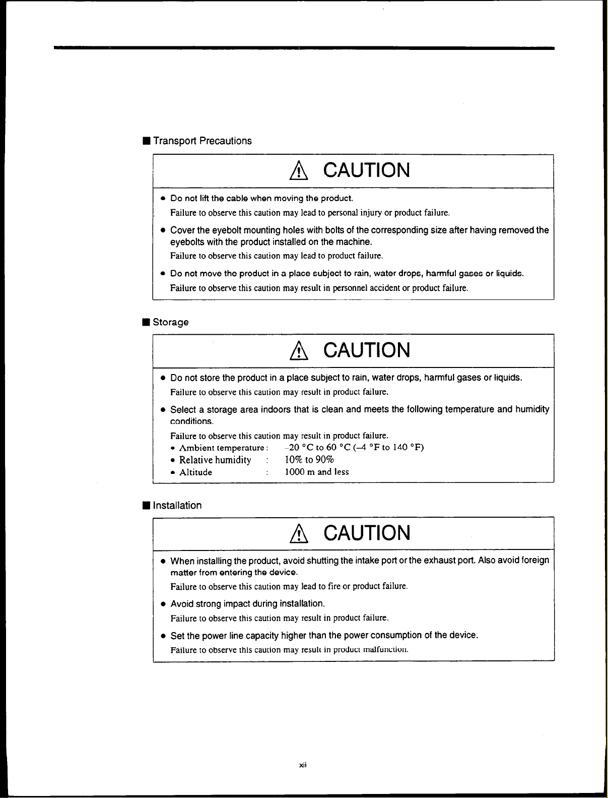
H Transport Precautions
A CAUTION
l
Do not lift the cable when moving the product.
Failure to observe this caution may lead to personal injury or product failure.
l
Cover the eyebolt mounting holes with bolts of the corresponding size after having removed the
eyebolts with the product installed on the machine.
Failure to observe this caution may lead to product failure.
l
Do not move the product in a place subject to rain, water drops, harmful gases or liquids.
Failure to observe this caution may result in personnel accident or product failure.
W Storage
A CAUTION
l
Do not store the product in a place subject to rain, water drops, harmful gases or liquids.
Failure to observe this caution may result in product
l
Select a storage area indoors that is clean and meets the following temperature and humidity
conditions.
Failure to observe this caution may result in product failure.
-20
l
Ambient temperature :
l
Relative humidity :
l
Altitude
“C to 60 “C (-4
10% to 90%
1000 m and less
failure.
“F to 140 “F)
n
Installation
I I
A CAUTION
l
When installing the product, avoid shutting the intake port or the exhaust port. Also avoid foreign
matter from entering the device.
Failure to observe this caution may lead to fire or product failure.
l
Avoid strong impact during installation.
Failure to observe this caution may result in product failure.
l
Set the power line capacity higher than the power consumption of the device.
Failure to observe this caution may result in product malfunction.
xii
Page 12
A CAUTION
l
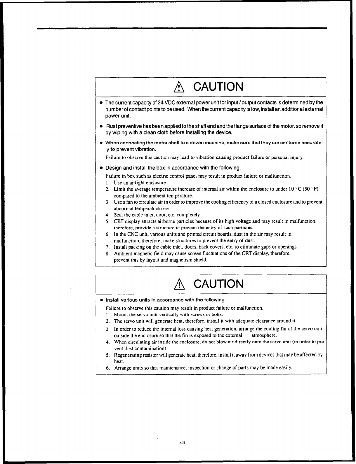
The current capacity of 24 VDC external power unit for input/output contacts is determined by the
numberof contact points to be used. When the current capacity is low, install an additional external
power unit.
l
Rust preventive has been applied to the shaft end and the flange surface of the motor, so remove it
by wiping with a clean cloth before installing the device.
l
When connecting the motor shaft to a driven machine, make sure that they are centered accurate-
ly to prevent vibration.
Failure to observe this caution may lead to vibration causing product failure or personal injury
l
Design and install the box in accordance with the following.
Failure in box such as electric control panel may result in product failure or malfunction.
I. Use an ainight enclosure.
2. Limit the average temperature increase of internal air within the enclosure to under 10 “C (50 “F)
compared to the ambient temperature.
3. Use a fan to circulate air in order to improve the cooling efficiency of a closed enclosure and to prevent
abnormal temperature rise.
4. Seal the cable inlet, door. etc. completely.
5. CRT display attracts airborne particles
therefore, provide a structure to prevent the entry of such particles.
6. In the CNC unit, various
units
malfunction, therefore, make structures to prevent the entry of dust.
7. Install packing on the cable inlet,
8. Ambient magnetic field may cause screen fluctuations of the CRT display, therefore,
prevent this by layout and magnetism shield.
because
of its high voltage and may result in malfunction,
and printed circuit boards, dust in the air may result in
doors,
back covers, etc. to eliminate gaps or openings.
A CAUTION
l
Install various units in accordance with the following.
Failure 10 observe this caution may result in product failure or malfunction.
I. Mount the servo unit vertically with screws or bolts.
2. The servo unit will generate heat, therefore, install it with adequate clearance around it.
3 In order to reduce the internal loss causing heat generation, arrange the cooling tin of the servo unit
outside the enclosure so that the fin
is exposed lo the external
4. When circulating air inside the enclosure, do not blow air directly onto the servo unit (in order lo pre
vent dust contamination).
5. Regenerating resistor will generate heat. therefore, install it away from devices that may
heat.
6. Arrange units so that maintenance. inspection or change of parts may be made easily.
XIII
atmosphere.
be affected by
Page 13
n
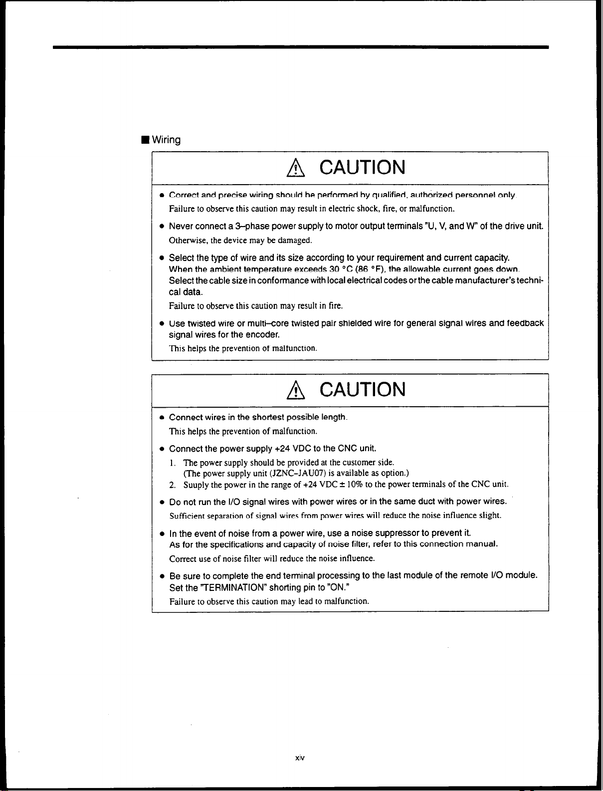
Wiring
A CAUTION
l
Correct and precise wiring should be performed by qualified, authorized personnel only.
Failure to observe this caution may result in electric shock, fire, or malfunction.
l
Never connect a 3-phase power supply to motor output terminals “U, V, and W” of the drive unit.
Otherwise, the device may be damaged.
l
Select the type of wire and its size according to your requirement and current capacity.
When the ambient temperature exceeds 30 “C (86 “F), the allowable current goes down.
Select the cable size in conformance with local electrical codes orthe cable manufacturer’s techni-
cal data.
Failure to observe this caution may result in fire.
l
Use twisted wire or multi-core twisted pair shielded wire for general signal wires and feedback
signal wires for the encoder.
This helps
the prevention of malfunction.
A CAUTION
l
Connect wires in the shortest possible length.
This helps the prevention of malfunction.
l
Connect the power supply +24 VDC to the CNC unit.
I. The power supply should be provided at the customer side.
(The power supply unit (JZNC-JAUO7) is available as option.)
2. Suuply the power in the range of +24 VDC 2 10% to the power terminals of the CNC unit.
l
Do not run the I/O signal wires with power wires or in the same duct with power wires.
Sufficient separation of signal wires from power wires will reduce the noise influence
l
In the event of noise from a power wire, use a noise suppressor to prevent it.
As for the specifications and capacity of noise filter, refer to this connection manual.
Correct
use
of noise filter will reduce the noise influence.
l
Be sure to complete the end terminal processing to the last module of the remote I/O module.
Set the “TERMINATION” shorting pin to “ON.”
slight.
Failure to observe this caution may lead to malfunction.
Page 14
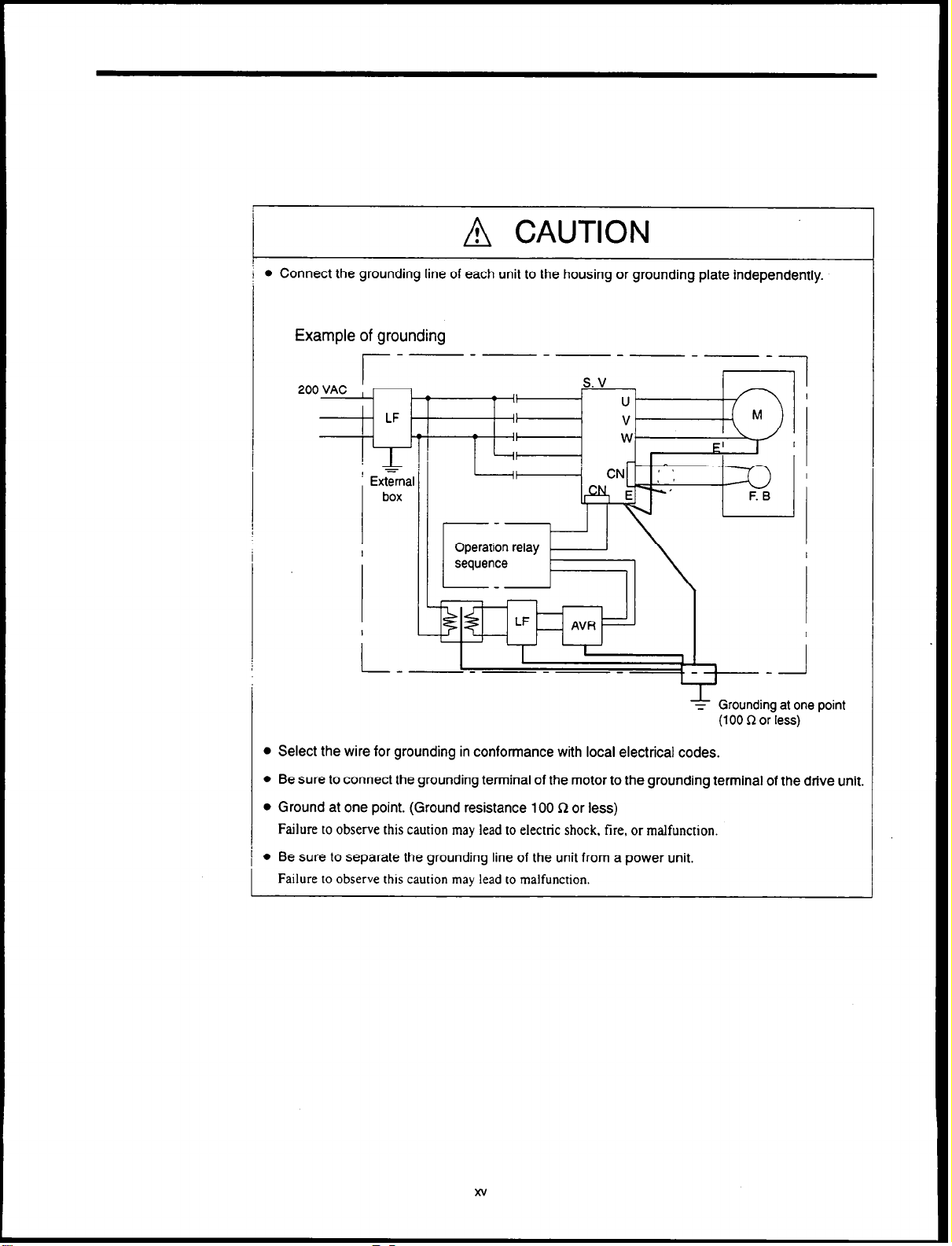
A CAUTION
0 Connect the grounding line of each unit to the housing or grounding plate independently.
Example of grounding
Grounding at one point
z
(100 R or less)
l
Select the wire for grounding in conformance with local electrical codes.
0 Be sure to connect the grounding terminal of the motor to the grounding terminal of the drive unit.
l
Ground at one point. (Ground resistance 100 R or less)
Failure to observe this caution may lead to electric shock. tire, or malfunction.
l
Be sure to separate the grounding line of the unit from a power unit.
Failure to observe this caution may
lead to malfunction.
xv
Page 15
n
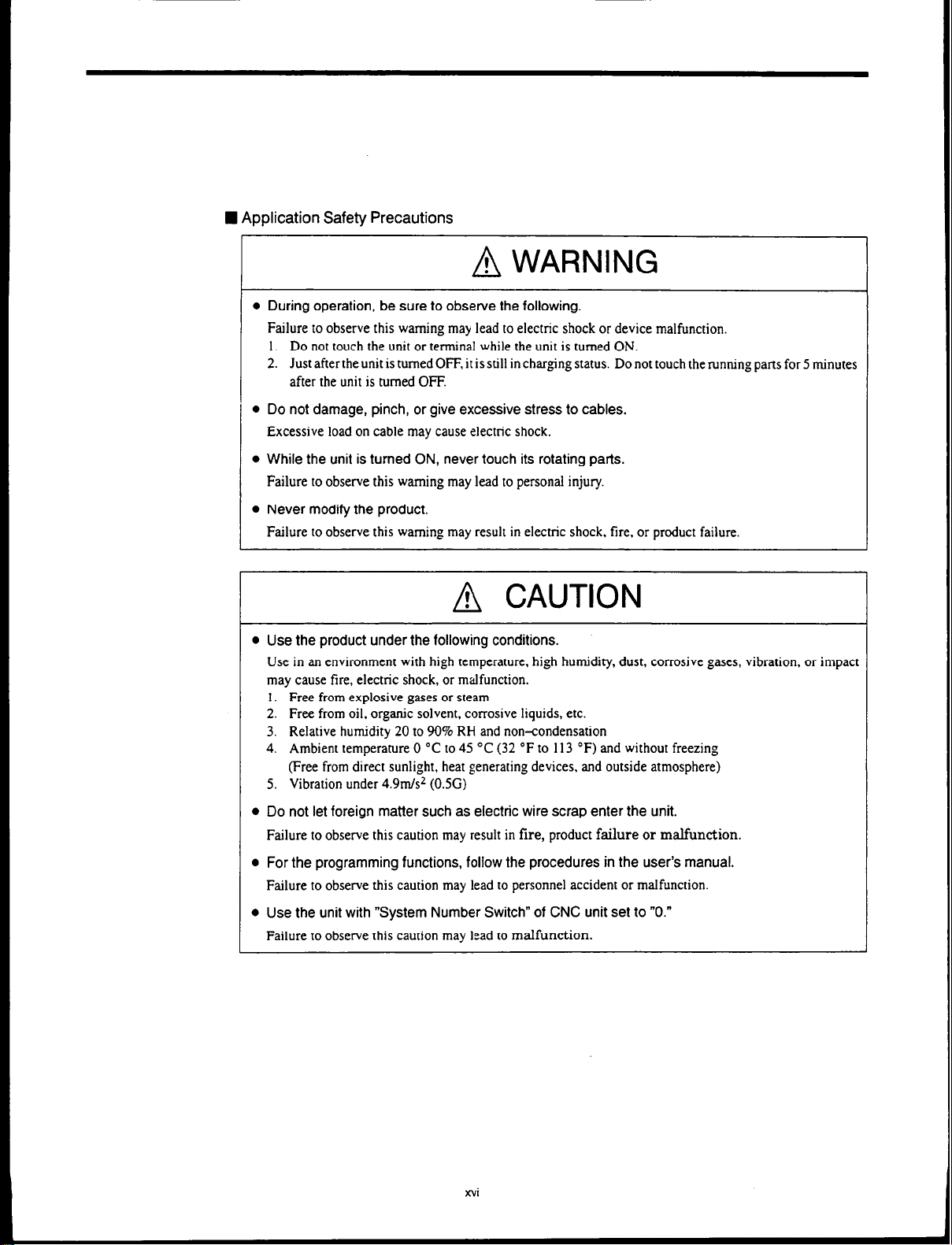
Application Safety Precautions
A WARNING
l
During operation, be sure to observe the following.
Failure to observe this warning may lead to electric shock or device malfunction.
1. Do not touch the unit or terminal while the unit is turned ON.
2. JustaftertheunitistumedOFF,itisstillinchargingstatus. Donottouchtherunningpattsfor5minutes
after the unit is turned OFF.
l
Do not damage, pinch, or give excessive stress to cables.
Excessive load on cable may
l
While the unit is turned ON, never touch its rotating parts.
cause electric shock.
Failure to observe this warning may lead to personal injury.
l
Never modify the product.
Failure to observe this warning may result in electric shock, fire, or product failure.
A CAUTION
l
Use the product under the following conditions.
Use in an environment with high temperature, high humidity, dust, corrosive gases, vibration, or impact
may cause fire, electric shock, or malfunction.
1. Free from explosive gases or steam
2. Free from oil, organic solvent, corrosive liquids, etc.
3. Relative humidity 20 to 90% RH
4. Ambient temperature 0 “C to 45 “C (32 “F to 113 “F) and without freezing
(Free from direct sunlight, heat generating devices, and outside atmosphere)
5. Vibration under 4.9m/s2 (0.5G)
and
non-condensation
l
Do not let foreign matter such as electric wire scrap enter the unit.
Failure to observe this caution may result in fire, product failure or malfunction.
l
For the programming functions, follow the procedures in the user’s manual.
Failure to observe this caution may lead to personnel accident or malfunction.
l
Use the unit with “System Number Switch” of CNC unit set to “0.”
Failure to observe this caution may lead to malfunction.
xvi
Page 16
A CAUTION
l
Before turning the unit ON again, wait for 2 seconds or more after turning it OFF.
Failure to observe this caution may lead to malfunction.
l
Never disassemble or modify the components of the unit.
Failure
to observe this caution may result in tire, product failure or malfunction.
l
Never change the set values of the components and variable resistors used in the control panel.
Failure to observe this caution may result in tire, product failure or malfunction.
xvii
Page 17
GENERALS
Chapter 1 describes the requirments for designing the controller..
CONFIGURATION
1 .l
1.1.1 System Configuration .....................
1.1.2
1.1.3
Connection between Devices
Connector Layout ........................
1.2 GENERAL SPECIFICATIONS
DESIGNOFBOX
1.3
1.3.1 Thermal Design
1.3.2 Dustproof Design .......................
1.3.3 Countermeasures against Magnetic Fields . 1 - 13
1.4 CABLE CLAMP AND SHIELDING
PACKAGING
1.5
1.51
1.5.2 Installation of CNC Unit
1.5.3 Installation of Servo Unit .................
General Notes
...................
..............
.........
...................
..........................
....
......................
..........................
..................
1 - 2
1 - 2
1 - 3
1 - 4
1 - 5
1-6
1 - 6
1 - 11
1 - 14
1 - 15
1 - 15
1 - 16
1 - 17
l-l
Page 18
1.1
CONFIGURATION
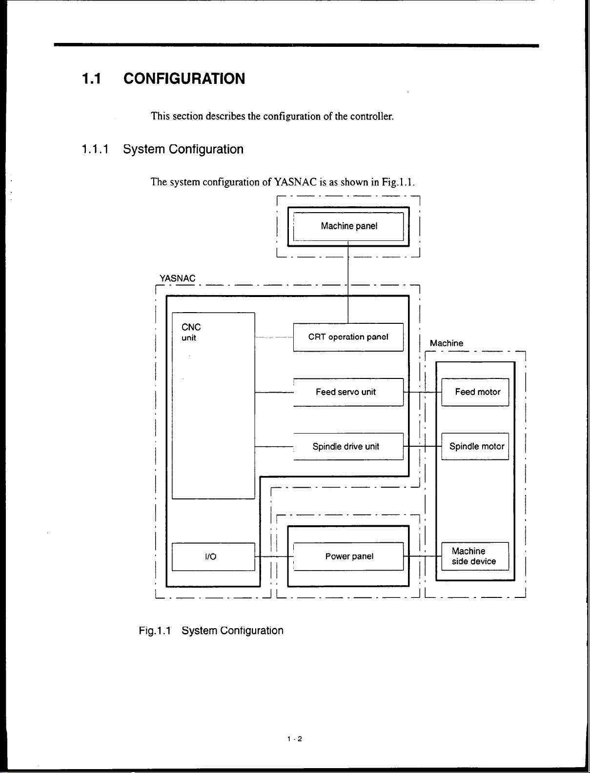
This section describes the configuration of the controller.
1.1.1
System Configuration
The system configuration of YASNAC is as shown in Fig. 1.1.
-_-_-_-_
r-
YASNAC
r--------‘--------
CNC
unit
1
1
l-
Machine
r-----
0 I
Ia
1
r-
L
I
Fig.1 .l System Configuration
I
---------,
J
--l
I
I
Spindle motor
I
Machine
J
1 side device
l-2
Page 19
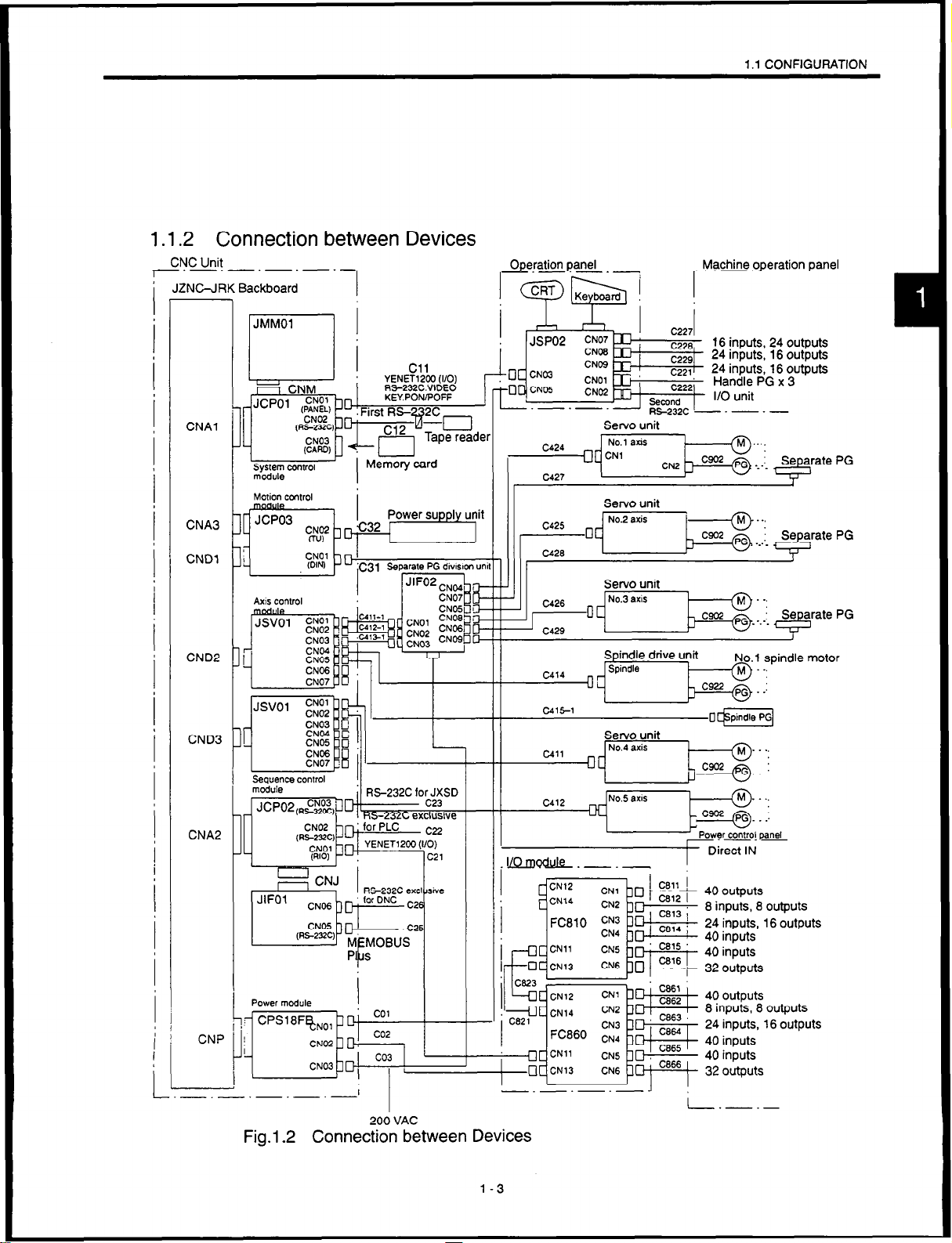
1.1.2 Connection between Devices
+JC&i!
1 f-jBy;@; , 1
-.-.-.-
I I I I I I
RS-232C.VldEd
KEYPONiPOFF
‘CNOZ'
CNAl
CNA3
I Ii I
(Rs-mc
L-&J 1 I I II
. -..-. --rr., -....
C425
-I No2 axis I
Servo unit
. - .~
1 .l CONFIGURATION
M ..,
CNDl
CND2
CND3
CNAP
CNP
Axis conlrol
-1 II
I
-.-.-.-
200 VAC
Fig.l.2 Connection between Devices
I
c4,, _ No.4 axis
CN14
Servo unit
-1 I
c?
40
outputs
8 inputs, 8 outputs
24 inputs, 16 outputs
40 inputs
40 inputs
32 outputs
40 outputs
8 inputs, 8 outputs
24 inputs, 16 outputs
40 inputs
40 inputs
32 outputs
L.-_-
1-3
Page 20
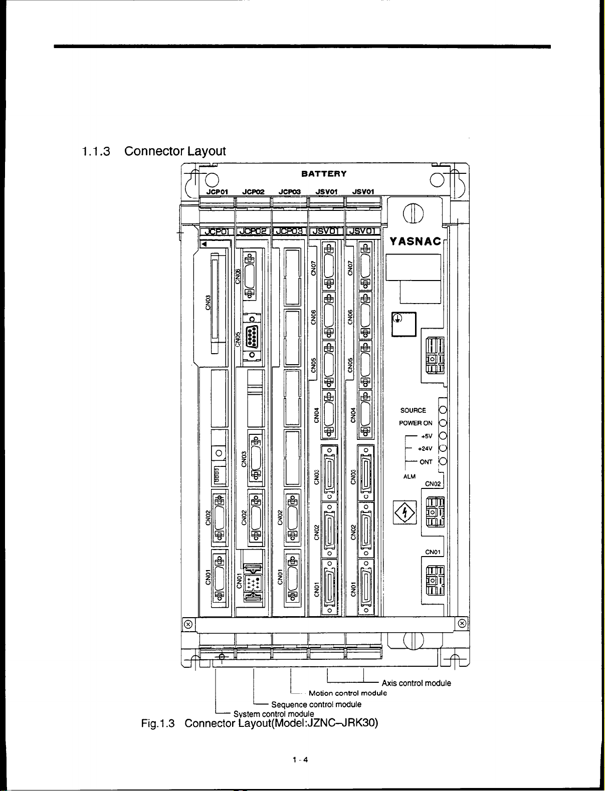
1.1.3 Connector Layout
BATTERY
Fig.1
UIUL ’
- Axis control mod: ’ u
Motion control module
LL
System control module
Connector Layout(ModekJZNGJRK30)
.3
Sequence control module
l-4
I
Page 21
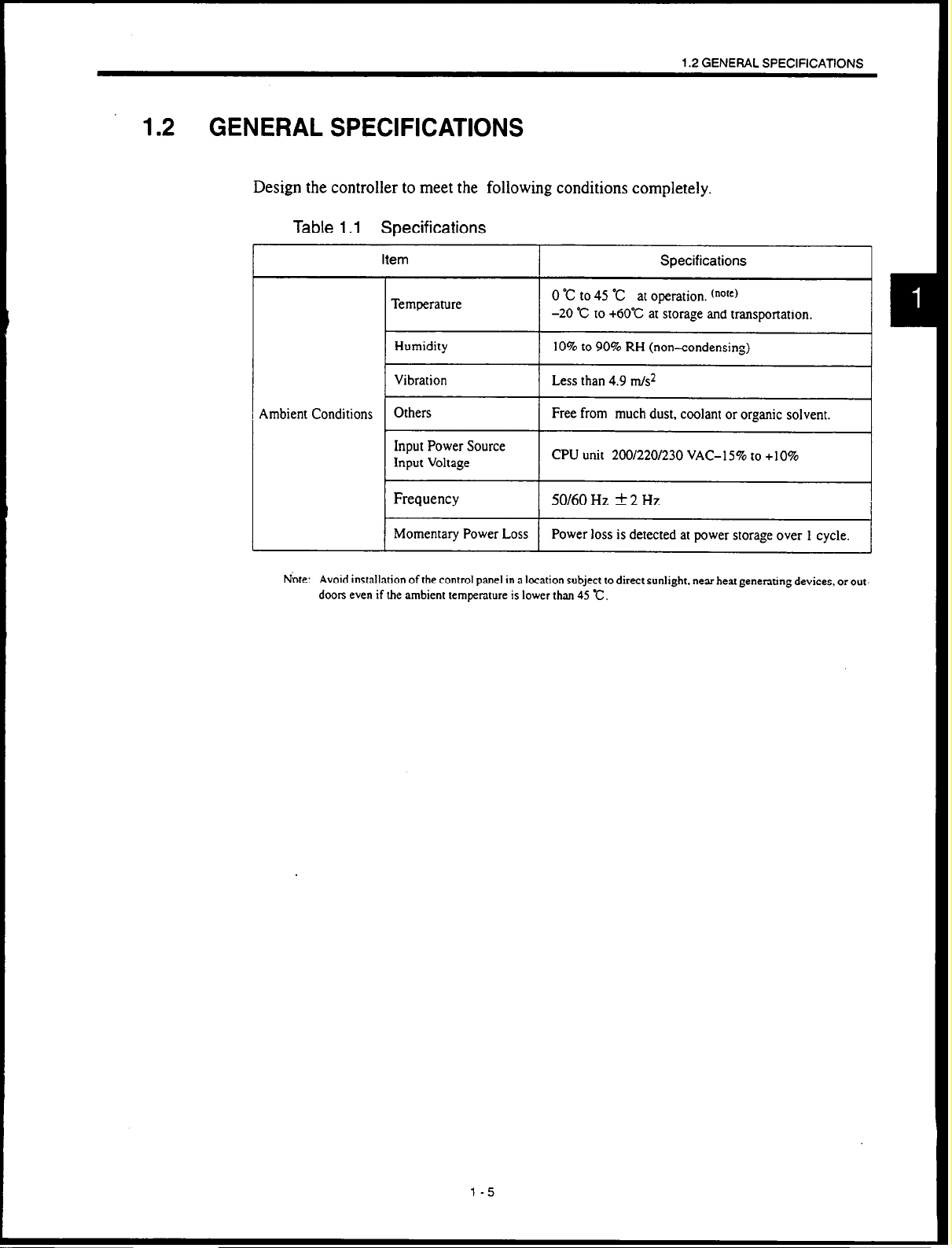
1.2 GENERAL SPECIFICATIONS
Design the controller to meet the following conditions completely.
Table 1.1 Specifications
Item Specifications
1.2 GENERAL SPECIFICATIONS
Ambient Conditions
Avoid installation of the control panel in B location subject to direct sunlight. near heat generating devices, or out-
Note:
doors even if the ambient temperature is lower than 45 c.
Temperature
Input Power Source
Input Voltage
Frequency
Momentary Power Loss
0 “C to 45 “C
at operation. (nore)
-20 “C to +6O’C at storage and transportation.
10% to 90% RH (non-condensing)
Free from much dust, coolant or organic solvent.
CPU unit 200/220/230 VAC-15% to +lO%
50160
Hz f 2 Hz
Power loss is detected at power storage over 1 cycle.
l-5
Page 22
1.3 DESIGN OF BOX
1.3.1 Thermal Design
Design should be made on the condition that the average temperature increase of internal air
of the box to contain the CNC unit and other units should be below 10”Cof the external air.
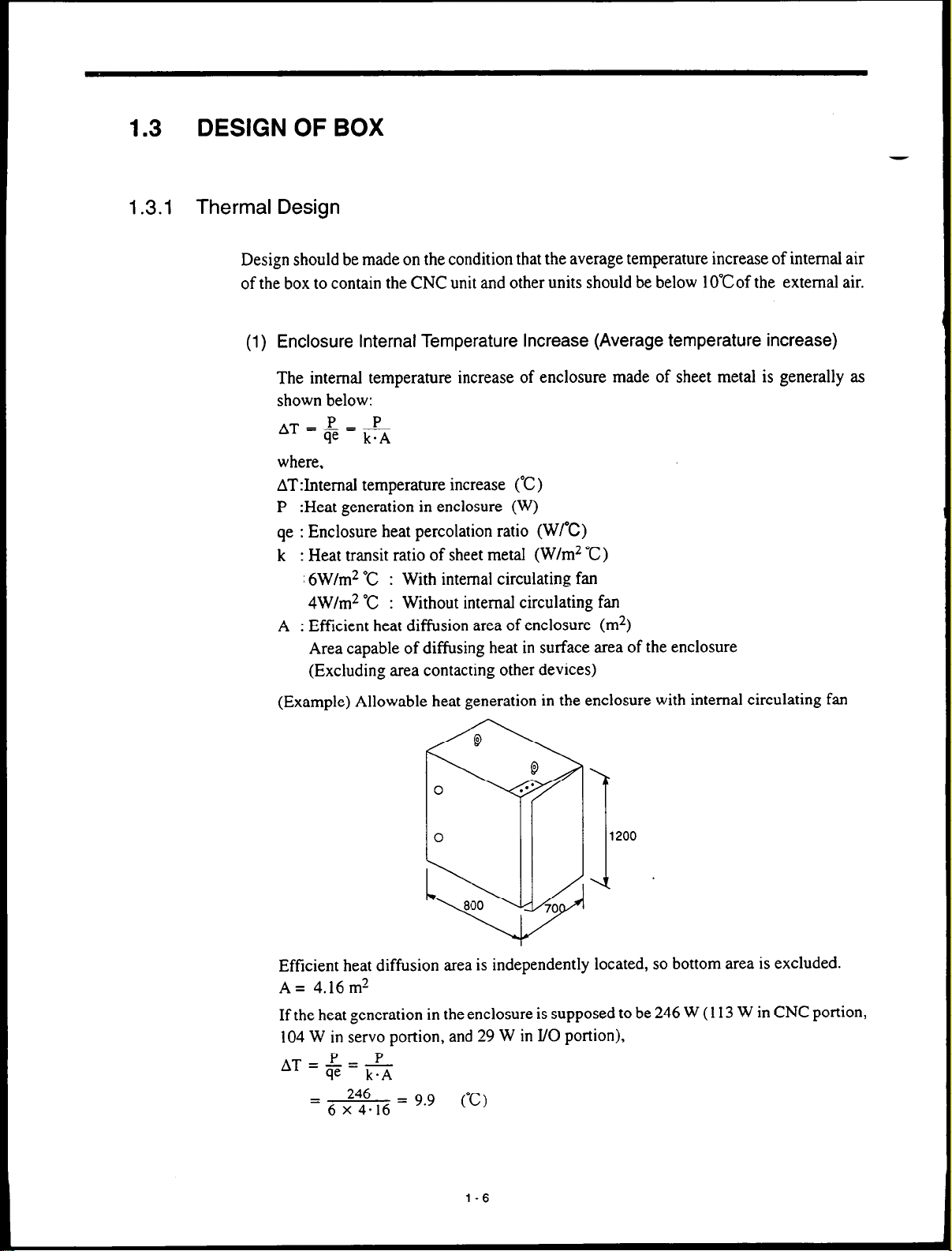
(1) Enclosure Internal Temperature Increase (Average temperature increase)
The internal temperature increase of enclosure made of sheet metal is generally as
shown below:
where,
AT:I.ntemaI temperature increase (‘C)
P :Heat generation in enclosure (W)
qe : Enclosure heat percolation ratio (WPC)
k : Heat transit ratio of sheet metal (W/m2
: 6W/m* “C : With internal circulating fan
4W/m* “C : Without internal circulating fan
A : Efficient heat diffusion area of enclosure (m*)
Area capable of diffusing heat in surface area of the enclosure
(Excluding area contacting other devices)
-
“C)
(Example) Allowable heat generation in the enclosure with internal circulating fan
8
8
.a*
1200
I;:
I
0
800
70
Efficient heat diffusion area is independently located, so bottom area is excluded.
A= 4.16m’
If the heat generation in the enclosure is supposed to be 246 W (113 W in CNC portion,
104 W in servo portion, and 29 W in I/O portion),
AT=F=m
P P
246
= 6 x 4.16 = “’
(C)
I
l-6
Page 23
1.3 DESIGN OF BOX
Therefore, it is all right to clear the temperature increase value below 10°C.
Where 10°C is exceeded, it is necessary to arrange separate cooling countermeasures.
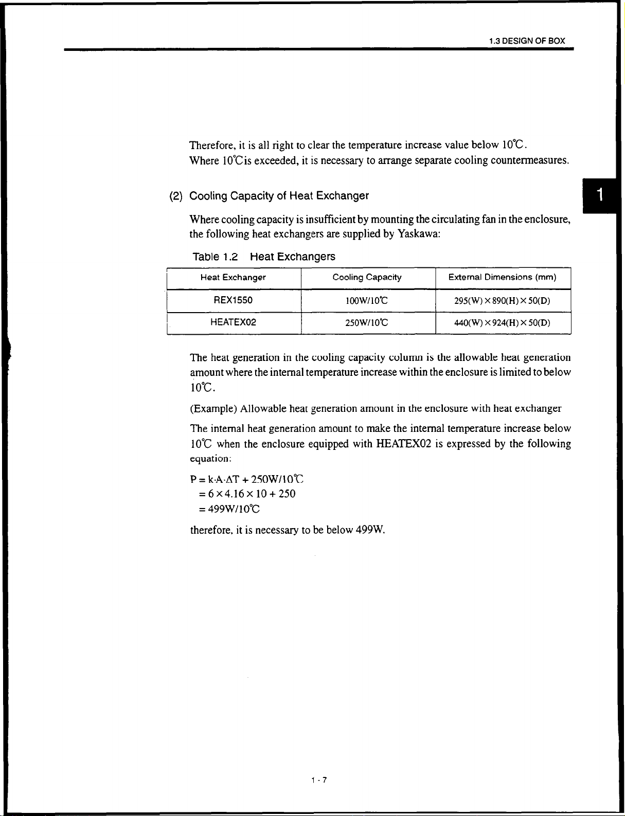
(2) Cooling Capacity of Heat Exchanger
Where cooling capacity is insufficient by mounting the circulating fan in the enclosure,
the following heat exchangers are supplied by Yaskawa:
Table 1.2 Heat Exchangers
I
I
I
I
Heat Exchanger
REX1 550
HEATEX02
I
I
I
Cooling Capacity External Dimensions (mm)
1 oow/ 1 O’C
25OW/lO”c
295(W) x890(H) X 50(D)
I
440(W) x924(H) X 50(D)
I
I
The heat generation in the cooling capacity column is the allowable heat generation
amount where the internal temperature increase within the enclosure is limited to below
10°C.
(Example) Allowable heat generation amount in the enclosure with heat exchanger
The internal heat generation amount to make the internal temperature increase below
10°C when the enclosure equipped with HEATEXO:! is expressed by the following
equation:
P = k.A.AT + 25OWllO”C
=6x4.16x10+250
= 499WI 10°C
therefore, it is necessary to be below 499W.
1-7
Page 24
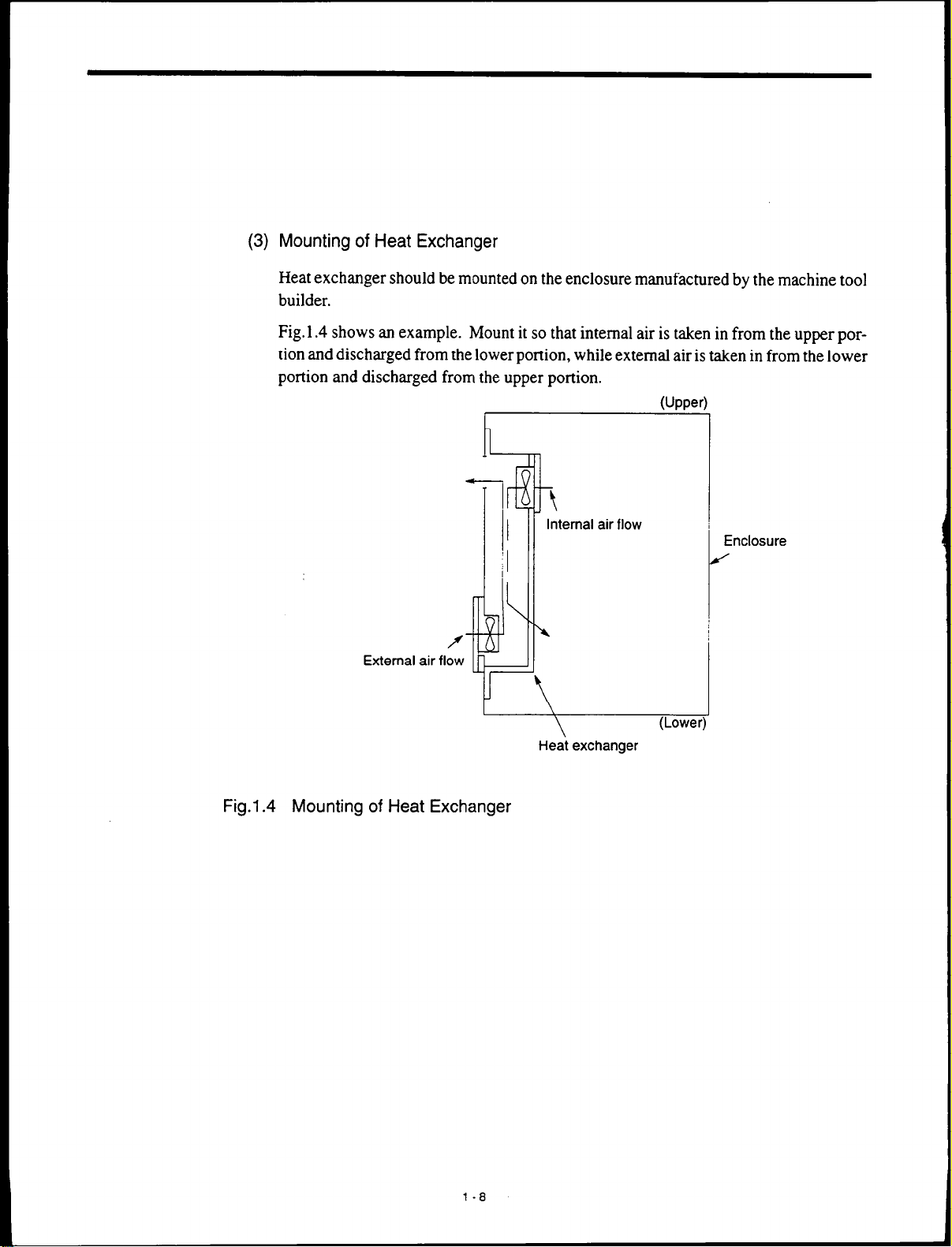
(3) Mounting of Heat Exchanger
Heat exchanger should be mounted on the enclosure manufactured by the machine tool
builder.
Fig. 1.4 shows an example. Mount it so that internal air is taken in from the upper portion and discharged from the lower portion, while external air is taken in from the lower
portion and discharged from the upper portion.
I
h-
External air
t-+YFw
Fig.l.4 Mounting of Heat Exchanger
3
7
Internal air flow
I
Heat exchanger
(Upper
Enclosure
J
Page 25
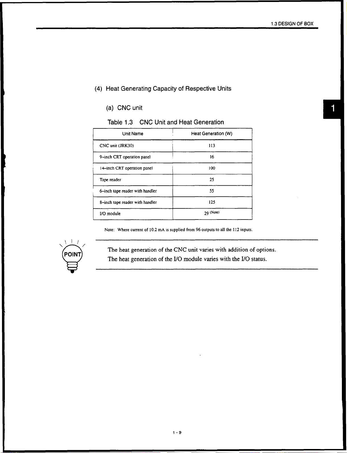
(4) Heat Generating Capacity of Respective Units
(a) CNC unit
Table 1.3 CNC Unit and Heat Generation
Unit Name
I
Heat Generation (W)
1.3 DESIGN OF BOX
\ ! I
\I.‘/
POINT
0
CNC unit (JRK30)
9-inch CRT operation panel
,
( 14-inch CRT operation panel
Tape reader
binch tape reader with handler 55
I
8-inch tape reader with handler 125
I/O module
Note: Where current of 10.2 mA is supplied from 96 outputs to all the I12 inputs.
I
1
I
I
I
29
113
16
loo
25
(Note)
The heat generation of the CNC unit varies with addition of options.
The heat generation of the I/O module varies with the I/O status.
I
I
l-9
Page 26
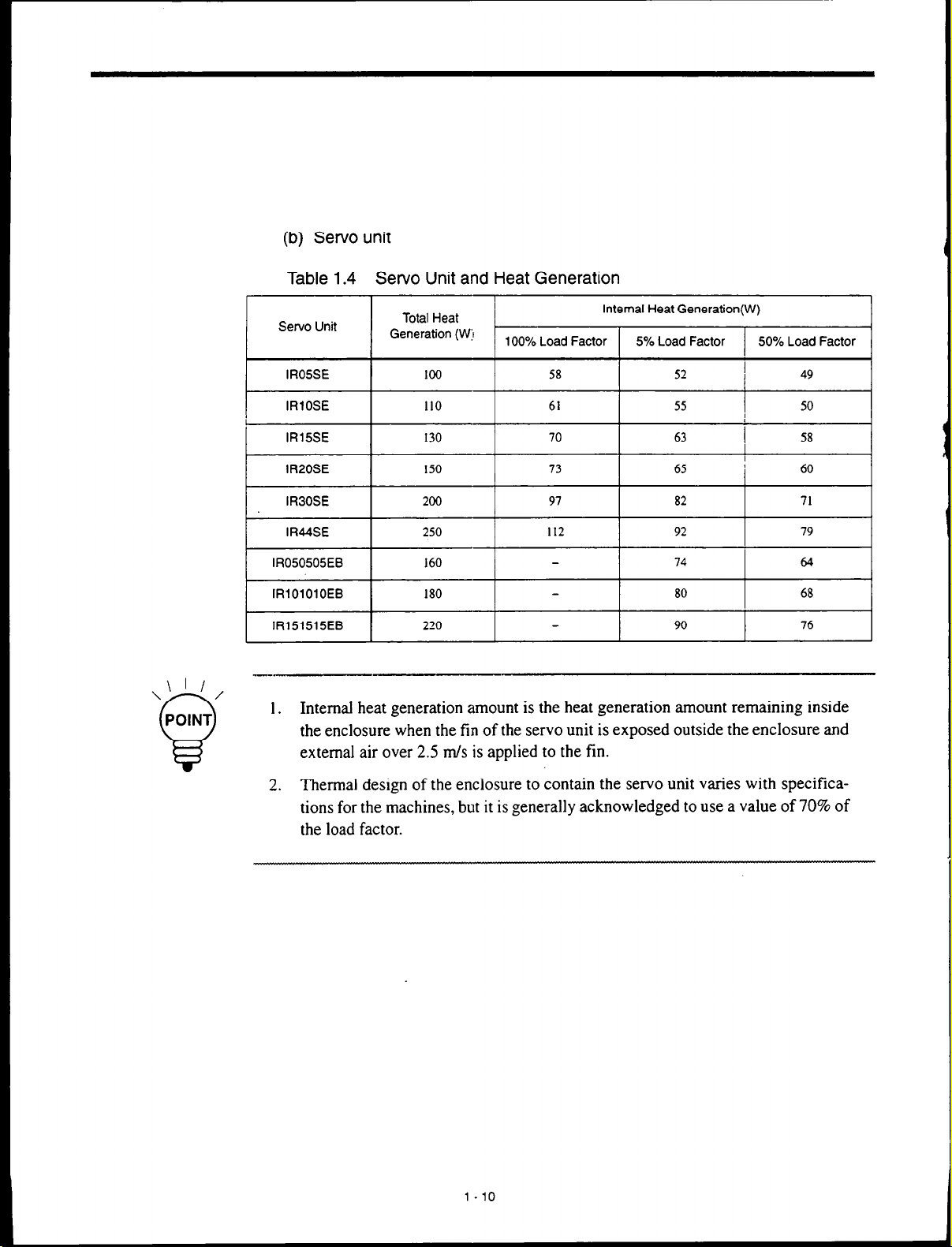
(b) Servo unit
Table 1.4 Servo Unit and Heat Generation
I
\’ ’ 5
POINT
Q
Servo Unit
IRlOSE
IR15SE 130 70 63 I 58
IR20SE 150 73 65 I
IRBOSE 200 97 82 71
IR44SE 250 112 92 79
IR050505EB 160 74 I 64
IRlOlOlOEB 180 80 68
IR151515EB 220 90 76
Internal heat generation amount is the heat generation amount remaining inside
1.
Total Heat
Generation (Wj
100 58
I
110
100% Load Factor 5% Load Factor 50% Load Factor
I
61
Internal Heat Generation(W)
I
I
52
55
I
I 5o I
I
I
49
60
the enclosure when the fin of the servo unit is exposed outside the enclosure and
external air over 2.5 m/s is applied to the fin.
2. Thermal design of the enclosure to contain the servo unit varies with specifications for the machines, but it is generally acknowledged to use a value of 70% of
the load factor.
I
Page 27
1.3.2 Dustproof Design
The inside of te CNC units and other boards (especially CRTs) to be packaged in enclosure
designed and manufactured by the machine tool builders are subject to airborne matter(dust,
oil mist, etc.) and may cause malfunction. Therefore, structures should be constructed so as
to prevent such matter from entering into the enclosure.
l
Use an airtight enclosure.
l
Seal the cable inlet with packing material. (Refer to Fig. 1 S.)
l
Secure the rear door lid with packing material. (Refer to Fig. 1.6.)
l
The front sides of units on the surface of the enclosure such as CNC operation
panels and tape readers are of dustproof type, however, avoid installing them
at places subject to coolant liquids. And seal the circumference of the mounting portion securely.
1.3 DESIGN OF BOX
l
Note that the CRT unit will attract airborne dust owing its high voltage. For
the mounting pendant box of the CRT unit, observe the following points:
l
Seal the clearance at the cable inlet, door, rear lid, etc. with packing material.
(Refer to Fig. 1.7.)
l
The CRT unit mounting surface has already been sealed with packing materi-
al, so use it as it is.
l
Close all the openings.
l
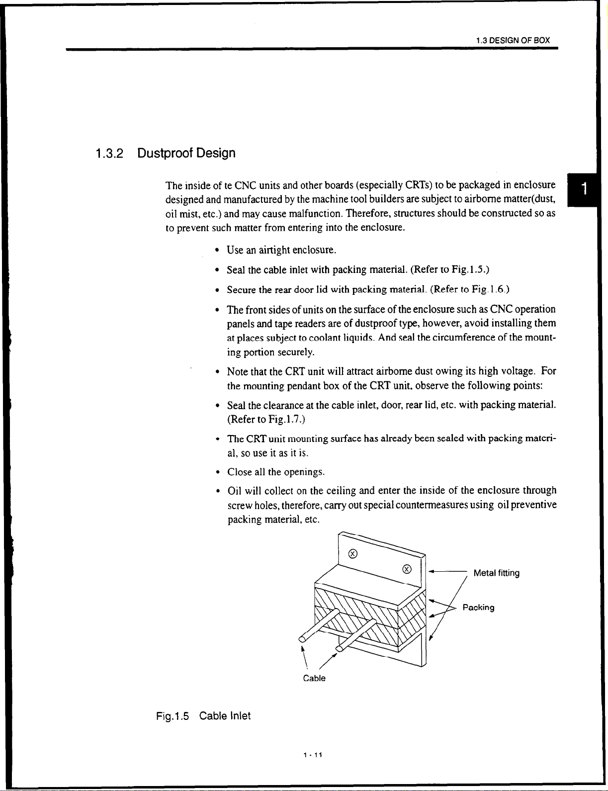
Oil will collect on the ceiling and enter the inside of the enclosure through
screw holes, therefore, carry out special countermeasures using oil preventive
packing material, etc.
- Metal fitting
Fig.l.5 Cable Inlet
Cable
l-11
Page 28
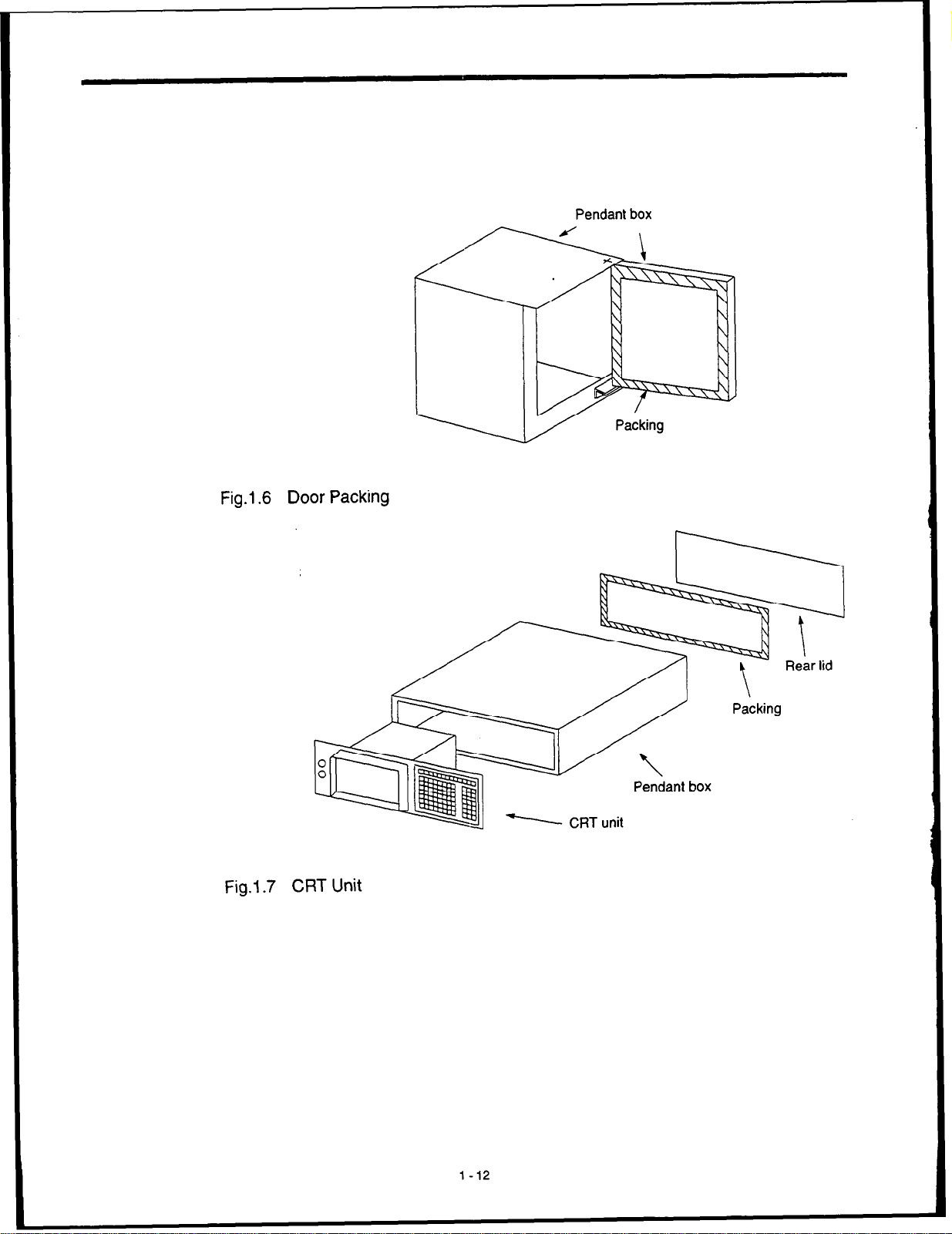
Fig.l.6 Door Packing
Pendant box
Fig.l.7 CRT Unit
Pendant box
N CRT unit
Page 29
1.3.3
Countermeasures against Magnetic Fields
The screen of CRT display may fluctuate owing to ambient magnetic fields.
Keep magnetism generating materials (for example, transformers, reactors, fans, electromagnetic switches, solenoid relays, exchange power supply cables, etc.) 300 mm from the
CRT display. This value of 300 mm is a general standard and may vary with different situa-
tions, therefore, pay sufficient attention to determining the layout of magnetism generating
sources, and finally check them with the machine.
1-13
Page 30
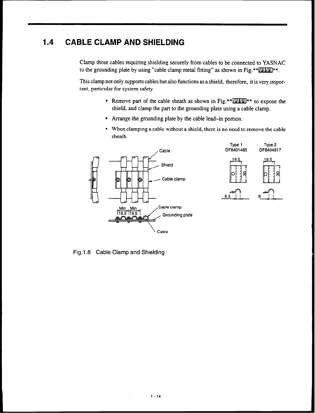
1.4
CABLE CLAMP AND SHIELDING
Clamp those cables requiring shielding securely from cables to be connected to YASNAC
to the grounding plate by using “cable clamp metal fitting” as shown in Fig.**m**.
This clamp not only supports cables but also functions as a shield, therefore, it is very impor-
tant, particular for system safety.
l
Remove part of the. cable sheath as shown in Fig.**=** to expose the
shield, and clamp the part to the grounding plate using a cable clamp.
l
Arrange the grounding plate by the cable lead-in portion.
l
When clamping a cable without a shield, there is no need to remove the cable
sheath.
Type 1
DF8401485 DF8404817
& f/j
We
2
\ Cable
Fig.l.8 Cable Clamp and Shielding
8 $ 8.ST
l-14
Page 31

1.5 PACKAGING
When designing the box to contain CNC unit and other units, take the following into consideration.
1.5.1 General Notes
l
l
l
l
l
1.5 PACKAGING
Use an air-tight enclosure.
Arrange packaging of units so that maintenance, inspection, removal, mount-
ing should be performed easily.
Secure clearance of 100 mm between parts and enclosure wall in order not to
restrict air flow.
When the operation panel is built-in the machine door or the like, it is subject
to vibration of the machine, therefore, be sure to reinforce it against vibration.
Limit the average temperature increase of internal air of enclosure to below
10 “C of the external air.
l
Use a fan to circulate air in order to improve the cooling efficiency of a closed
enclosure and to prevent local temperature increase. (As a standard, arrange
so that air over In-r/s flows over the surface of printed circuit boards within
various units.)
l
Do not blow the fan air directly onto printed circuit boards.
l
In order to prevent malfunctions owing to noise, keep various units 10 mm
away from cables or parts over 90 VDC, cables such as AC power supply or
parts.
l
When wiring, observe the following points:
Separate AC lines from DC lines.
Separate the primary side and the secondary side of transformer, line filter, etc.
1-15
Page 32

1.52 installation of CNC Unit
When installing the CNC unit, observe the following notes:
l
Mount the CNC unit in the direction as shown in Fig.l.9.
Fig.l.9 Mounting of CNC Unit
(Upper)
Power
SUPPlY
l
This CNC unit has a built-in fan so that air flows at lm/s over the upper side
of the unit.
l
Arrange clearance over 50 mm above the CNC unit and over 100 mm below
it for ventilation and ease of maintenance.
1-16
Page 33

1.5.3
Installation of Servo Unit
l
Since the servo unit is a wall-mounted type, mount it vertically with screws
or bolts.
l
Arrange it so that maintenance, inspection and parts replacement can be made
easily.
l
Since the servo unit will generate heat to some extent, arrange other
units or devices with sufficient space above and below it.
l
In order to reduce the internal loss from the viewpoint of heat generation, arrange the cooling fin of the servo unit outside of the enclosure, and blow external air on the cooling fin. (2 m/s)
l
When circulating the internal air in the enclosure, do not blow air directly to
the servo unit (in order to prevent dust contamination).
l
For the installation of the feed servo unit and the spindle drive unit, refer to
the respective operation manuals.
l
In order to reduce the internal loss from the viewpoint of heat generation, it
is recommended to arrange the cooling fin of the servo unit outside of the enclosure. This helps make the enclosure closed structure and make the capacity
of the heat exchange unit small.
Fig.1 .lO
1
Cooling fin
-i
External air
Cooling Fin Installed Outside of Enclosure
c
1
1-17
-
Feed servo unit and
.
4 spindle drive unit
-
Page 34

2
CONNECTION OF POWER SUPPLY
Chapter 2 describes the power supply connection.
2.1 CONNECTION BETWEEN DEVICES . . 2 - 2
2.1 .l
Power Supply to CNC Unit ................
2 - 2
2.1.2
2.2 DETAILED CONNECTION
2.2.1
2.2.2 Power Supply to Converter Unit
Power Supply to Converter Unit
Power Supply to CNC Unit ................
............ 2 - 2
............
............
2 - 3
2 - 3
2 - 3
2-1
Page 35

2.1
CONNECTION BETWEEN DEVICES
This section describes the connection between devices.
2.1.1
2.1.2
Power Supply to CNC Unit
CNC unit
Fig. 2.1
Power Supply to CNC Unit
Power Supply to Converter Unit
Converter unit
Fig. 2.2
Power Supply to Converter Unit
2-2
Page 36

2.2 DETAILED CONNECTION
This section describes the detailed connection of power supply.
2.2 DETAILED CONNECTION
2.2.1
2.2.2
Power Supply to CNC Unit
Fig. 2.3 Detailed Connection of Power Supply
Power Supply to Converter Unit
:onverter unit
:IMR-MR5
R/L1 (
L
Single-phase
200/220/230 VAC - 15 to 10%
50160 Hz f 2 Hz
560vA
1MC 1 MCCB
- R 2OOQ20/230 VAC
- 15 to 10%
- s 50160 Hz -c 2 Hz
Fig. 2.4
A2
Detailed Connection of Power Supply
2-3
t
Page 37

CONNECTION OF
CNC OPERATION PANEL
Chapter 3 describes the connection between the CNC unit
and the CNC operation panel.
3.1 CONNECTION BETWEEN DEVICES . . 3 - 2
3.1 .l
3.2 DETAILED CONNECTION OF
CNC OPERATION PANEL . . . . . . . . . . . . 3 - 3
Connection with 9-inch CRT Operation Panel 3 - 2
3.2.1
3.2.2
Connection with 9-inch CRT Operation Panel 3 - 3
General Notes on the Connenction of
CRT
Operation Panel . . . . . . . . . . . . . . . . . . . . . 3 - 4
3-1
Page 38

3.1
CONNECTION BETWEEN DEVICES
This section describes the connection between CNC unit (including the power supply unit)
and CNC operation panel and the type of connector as well as the cable specifications.
3.1 .l
Connection with 9-inch CRT Operation Panel
CNC unit
~---
JANCD-JCPOl
CNOl
10220-52A2JL
CPS-18FB
I
g-inch CRT operation panel
-- -12
J
CNOl
17204&l
Fig. 3.1 Connection between Devices
I-
3-2
Page 39

3.2 DETAILED CONNECTION OF CNC OPERATION PANEL
3.2
3.2.1
DETAILED CONNECTION OF CNC OPERATION PANEL
This section describes the detailed connection between CNC unit (including the power unit)
and CNC operation panel and the type of connector as well as the cable specifications.
Connection with 9-inch CRT Operation Panel
CNC unit
CNOl-12,,
CNOl-1 )/
CNOl-2 ).
CN01-8).
CNOl-9 ),
CNOl-181,
CNOl-191,
CNOl-162,
.G.
.
.
.
POFF : ’
PCOM : ’
VIDEO : 1
‘VIDEO
VCLK :
*VCLK
HSYNC 0 :
’ *HSYNC : p ’
VSYNC : ’
‘VSYNC
FG I._,’
OjP: ’
’ {P:
: tP0
O-inch CRT operation panel
----
/
,,CN03-12
.&NOW
&NO%2
. CN03-8
.(CN03-9
.(CN03-18
.cCN03-19
.(CN03-16
,(CN03-17
/,
11 Hoodcase
Fig. 3.2
Connection with g-inch CRT Operation Panel
3-3
Page 40

3.2.2
General Notes on the Connenction of CRT Operation Panel
(1) Wiring of the Power ON/OFF Switch
For a standard horizontal g-inch CRT operation panel, the wiring of the power ON/OFF
switch has been made by Yaskawa. For a vertical type, use the wiring in the figure below or external ON/OFF switch.
Operation panel
“Power ON” pushbutton
Page 41

3.2 DETAILED CONNECTION OF CNC OPERATION PANEL
(2) Switches for External Power Supply
External power supply ON/OFF is selected by the following switches:
Switches (SWl, 2) are arranged on JANCD-JCP03.
JANCD-JCPOB
100
SW1
l
For setting external power ON/OFF effective, and operation panel power ON/
SW2
CN02
I I
CNOl
OFF effective
l
For setting external power ON/OFF invalid, and operation panel power ON/
OFF effective
l
For setting external power ON/OFF effective, and operation panel power ON/
OFF invalid
-
l
Do not set. Setting shown below disables the power ON/OFF.
(3) Factory Setting
-
Before shippment, the operation panel power ON/OFF is set to “Effective,” and the external power ON/OFF is set to “Invalid.”
3-5
Page 42

4
CONNECTION OF
MANUAL PULSE GENERATOR
Chapter 4 describes the connection between the CNC operation panel and the manual pulse generator and type of the
connector as well as the cable specifications.
4.1 CONNECTION BETWEEN DEVICES . . 4 - 2
4.1.1 Connection with 9-inch
CRT Operation Panel . . . . . . . . . . . . . . . . . . . . . 4 - 2
4.2 DETAILED CONNECTION OF
MANUAL PULSE GENERATOR . . . . . . . 4 - 3
4.2.1
4.2.2 Parallel I/F . . . . . . . . . . . . . . . . . . . . . . . . . . . . . . 4 - 4
Non-parallel I/F.. . . . . . . . . . . . . . . . . . . . . . . . . 4 - 3
4-1
Page 43

4.1
CONNECTION BETWEEN DEVICES
This section describes the connection between the CNC operation panel and devices of the
manual pulse generator, and the type of connector, and the cable specifications.
4.1 .l Connection with 9-inch CRT Operation Panel
CNC operation panel
-1
JANCD-JSP02
---
Fig. 4.1
CNOl
10220-6202JL
Connection between Devices
Manual pulse generator No
Manual pulse generator No.2
.l
4-2
Page 44

4.2 DETAILED CONNECTION OF MANUAL PULSE GENERATOR
4.2
DETAILED CONNECTION OF MANUAL PULSE GENERATOR
This section describes the detailed connection between the CNC operation panel and the
manual pulse generator.
4.2.1 Non-parallel I/F
CNC operation panel
JANCDJSP02-1.2
LNUl-1 I /,UV
’ I
Manual pulse generator No.1
I \
Manual pulse generator No.2
Fig. 4.2 Detailed Connection of Manual Pulse Generator
(Model:PREH-2E5T/lOO-M)
Use the cable within 5 m for non-parallel type I/F.
Connect FG and the cable to the case using cable clamp metal fitting.
4-3
Page 45

4.2.2 Parallel I/F
CNC operation panel
JANCD-JSPOPa
CNOl-16
CNOl-17 _
CN01-6 ,PAHB ; - ‘,
PAHl ’ - ’
Manual pulse generator No.1
Manual
Manual pulse generator No.3
,3
a *PAH3 ,4
pulse generator No.2
\ I I
\’ ‘/
POINT
0
H
Fig. 4.3
Detailed Connection of Manual Pulse Generator (Parallel I/F)
Use the cable within 15 m in the case of parallel I/F.
Parallel type manual pulse generator is not provided by Yaskawa.
Connect FG and the cable to the case using cable clamp metal fitting.
Page 46

CONNECTION OF POWER ON/OFF
EXCLUSIVE SIGNAL
Chapter 5 describes the connection of the power ON/OFF
exclusive signal.
5.1 CONNECTION BETWEEN DEVICES . . 5 - 2
51.1
5.2 DETAILED CONNECTION OF
POWER ON/OFF EXCLUSIVE SIGNAL 5 - 3
52.1
5.3 DETAILS OF SIGNAL . . . . . . . . . . . . . . . . 5 - 4
5.3.1 Servo Power ON (SVMX), Brake Release
Connection to CNC Unit . . . . . . . . . . . . . . . . . . 5 - 2
Connection to CNC Unit . . . . . . . . . . . . . . . . . . 5 - 3
(BKX)
Output . . . . . . . . . . . . . . . . . . . . . . . . . . . . 5 -
4
5.3.2
5.3.3
Emergency Stop (*ESP) Input . . . . . . . . . . . . . 5 - 5
External Power ON/OFF (EON, EOF, ECOM)
Input . . . . . . . . . . . . . . . . . . . . . . . . . . . . . . . . . . . 5-5
Page 47

5.1
CONNECTION BETWEEN DEVICES CONNECTION BETWEEN DEVICES
This section describes the connection between devices related to the power ON/OFF exclu- This section describes the connection between devices related to the power ON/OFF exclu-
sive signal, the type of connector. and the cable specifications. sive signal, the type of connector. and the cable specifications.
5.1.1
Connection to CNC Unit
CNC unit
JANCD-JCP03
10220-52A2JL
Fig.
5.1 Connection between Devices
CN02
C32 UL20276 AWG28 x 10 pairs
101204000VE
(1032~52AO-008)
Power supply interface
5-2
Page 48

5.2 DETAILED CONNECTION OF POWER ON/OFF EXCLUSIVE SIGNAL
5.2 DETAILED CONNECTION OF POWER ON/OFF EXCLUSIVE
SIGNAL
This section describes the detailed connection of the power ON/OFF exclusive signal.
5.2.1 Connection to CNC Unit
CNC unit
-----JANCD-JCPOB
Machine end
Machine end release
External power ON
External power OFF
Fig. 5.2
Detailed Connection of Power ON/OFF Exclusive Signal
For the relay of SVMX, BKX, use miniature relay 24 VDC.
(Recommended part: MY-4Z by OMRON)
-___--.--
.-..-.--.-I
5-3
Page 49

5.3
DETAILS OF SIGNAL
This section describes the signals to be used in the power supply sequence.
5.3.1
Servo Power ON (SVMX), Brake Release (BKX) Output
(1) Signal
SVMX : This is the output that turns ON when the power is supplied to the servo unit.
BKX : This is the output to release the holding brake of the feed axis (vertical axis).
(2) Power Supply Sequence
Power supply sequence is executed as shown below:
@ Supply power to the controller.
@ : Perform the power supply operation (Press [POWER ON] pushbutton on the CNC
@ Perform the power supply operation again. SVMX output is closed, and the servo
Names and Descriptions
When a servo unit is externally installed, supply power to the servo unit by
this output.
operation panel, or close the circuit between the external EON and ECOM.), and
the logic circuit power is turned ON.
power is turned ON.
When a servo unit is externally installed, carry out servo power ON sequence by
SVMX output.
@ After completion of servo ready (servo clamp status), BKX output is closed
after the time set by parameter. Release the brake unit by this signal.
@ After SVMX output is closed and the controller is ready, if external preparation
has been completed, close the MRD (machine ready completed) input of the general-purpose output module. “RDY” is displayed on the CRT screen, and operation is possible .
5-4
Page 50

POWER ON PB or
EON input
POWER OFF PB or
EOF input
*ESP input
;
SVMX output
Servo ready completed
(internal status)
BKX output
MRD input
1
Alarm code “3000 TIDY” 3302” “3000
4
>---a
“2190
Fig. 5.3 Power Supply Sequence
[RESET] key ON
4
5.3.2
5.3.3
Emergency Stop (*ESP) input
When the emergency stop input circuit is opened, the controller stops all the actions and turns
SVMX and BKX OFF. During emergency stop of the general-purpose I/O module, it makes
output (*ESPS) “open.”
In response to the emergency stop input, the servo should DB stop and spindle stop with
brake using the delay circuit.(The spindle coasts after the main connector 1MC is “opened”
by the delay timer.)
External Power ON/OFF (EON, EOF, ECOM) Input
The controller may be turned ON/OFF by external input in the same manner as by the POWER ON/OFF pushbutton on the CNC operation panel.
Setting the portion between EON and ECOM “closed” in the state the EOF and ECOM is
“closed” turns ON the logic circuit of the controller or the servo power.
Setting the portion between EON and ECOM “open” turns OFF the logic circuit of the controller and the servo power.
5-5
Page 51

6
CONNECTION OF
FEED SERVO UNIT
Chapter 6 describes the connection between the CNC unit,
the feed servo unit, and the servo motor.
6.1 CONNECTION BETWEEN DEVICES . . 6 - 2
6.1.1 Connection with l-axis Servo Unit ......... 6 - 2
6.1.2 Connection with 3-axis Servo Unit ......... 6 - 4
6.2 DETAILED CONNECTION WITH
FEED SERVO UNIT ................. 6 -6
6.2.1 No.1 Axis ............................... 6 - 6
6.2.2
6.2.3 No.3 Axis ............................... 6 - 7
6.2.4 No.4Axis ............................... 6-7
6.2.5 No.5 Axis ............................... 6 - 8
6.2.6
6.3 DETAILED CONNECTION OF SERVO UNIT
MAINCIRCUIT ..................... 6-10
6.3.1
6.3.2
6.4 USE OF SERVO UNIT .............. 6 - 12
6.4.1
6.4.2
No.2 Axis ............................... 6 - 6
IRTypeServoUnit ....................... 6-8
Connection with l-axis Servo Unit ........ 6 - 10
Connection with 3-axis Servo Unit ........ 6 - 11
Noise Suppression ...................... 6 - 12
Protection of Power Line ................. 6 - 16
6-1
Page 52

CONNECTION BETWEEN DEVICES
This section describes the connection between the CNC unit, the feed servo unit, and the servo motor, as well as the type of connector and the cable specifications.
6.1 .l
Connection with l-axis Servo Unit
CNC unit
JANCD-JSVOl
No.1
- -, 5w80 Hr. 3-#lase
PCR-E28Lh4DTSO
PCFM28LMOTSO
PCR-ER28LMOTSD
CNOl
CNOZ
CN03
ZCOt22W23OVAC
I I
Feed servo unit Feed motor
__-..-
@3
MR-2ofOl (MFmL)
KOW-sBtype DE&UX)os3
3
Da
Is31OaB2a-295
1sc57-1
PG
0
CACR-!RClOSEB
Fig. 6.1
Connection of Cable (No.1 axis to No.3 axis)
6-2
Page 53

6.1 CONNECTION BETWEEN DEVICES
CNC unit
IANCD-JSVOI
40.1
--
PCR428LMDTSD
PCR-E28LMDTSD
PCR428LMDTSD
CNOl
CNM
CNC!3
PCR-EZBFC
Feed servo unit
CACR-IROOSEB
CACR-lROOSEB
1CN
PCR-E28LMD
‘I
No.4 axis
XN
MR-ZORMA
No.5 axis
2CN
MR-ZORMA
Feed motor
@3
@3
I
Fig. 6.2
Connection of Cable (No.4 axis and No.5 axis)
6-3
Page 54

6.1.2 Connection with 3-axis Servo Unit
200/220/230 VAC
CNC unit
IANCD-JSVOI
W.1
50160 Hi
!, .
3-phase
B
Servo unit (for 3 axes)
CN2
l-1782934
CNl;
MR-2OFtMP
KOW-SB type
DE8400093
CNOl
PCR-E28LMD
CNOZ
PCR-E28LMD
CN03
PCR-E28LMD
227,
ICI-
‘CR-E28FC
‘CS-E28LB)
s271
ICI-
‘CR-E28FC
“CS-E28LB)
227,
IC-
‘CR-E28FC
PCS-E28LB)
CNll
PCR-EZBLMD
CN31
PCR-E28LMO
CN3
1-178138-2
CN3;
MR-20RMi
KQW-SB type
DE8400093
KOW-SB type
DE8400093
-
PG 1 No.2 axis
Fig. 6.3
Connection of Main Circuit
6-4
Page 55

200/220/230 VAC
50160 Hz, %phase
6.1 CONNECTION BETWEEN DEVICES
I
m
Fig. 6.4
CN12
MRGORMA
MR
Connection of Main Circuit
I
I
KOW-SB twe
MS3108B2&29S
KQW-SB twe
6-5
Page 56

6.2 DETAILED CONNECTION WITH FEED SERVO UNIT
This section describes the detailed connection between the CNC unit, the feed servo unit,
and the servo motor.
6.2.1 No.1 Axis
CNC unit
6.2.2 No.2 Axis
r-1
L--l 1
Fig. 6.5 No.1 Axis
CNC unit
No.1
P 1
JANCD-JSVOl
CACRdROOSEE
Feed servo unit (No.2 axis)
c
2s
c
zc
;> ICN-15
L---.--l
zc
CACR-IROOSEB
‘2’
Fig. 6.6 No.2 Axis
6-6
Page 57

6.2.3 No.3 Axis
6.2 DETAILED CONNECTION WITH FEED SERVO UNIT
6.2.4 No.4 Axis
CNC unit
p”
L---l I
JANCD-JSVOl
Fig. 6.7 No.3 Axis
Feed servo unit (No.3 axis)
r--i
L-I
CACR-IROOSEB
&
CNC unit
I
Fig. 6.8
No.4 Axis
FeyEunit (No.4 ajis)
l----I t
CACR-IROCISEB
6-7
Page 58

6.2.5 No.5 Axis
CNC unit
Fig. 6.9 No.5 Axis
6.2.6 IR Type Servo Unit
For IR type servo unit, the setting of connector number to be connected to CNC unit is made
by SW2.
(1) IRCICISEB Type (for 1 axis) Servo Unit
SW1 : This is for test, so do not change the default setting; SWl-0 to 3: open
SW2 : Axis setting (to determine the connector to be connected)
SW2
0
1 JSVOI CN02
2
3
to
F
CNC Side Connection Connector
JSVOl CNOl
JSVOI CN03
Invalid
I
6-8
Page 59

6.2 DETAILED CONNECTION WITH FEED SERVO UNIT
(2) IROOEB Type (for 3 axes) Servo Unit
SW1 : This is for test, so do not change the default setting; SWl-0, 1:
short-circuited, SWI-2, 3: open
SW2 :
Axis setting (to determine the connector to be connected)
SW2 CNll Connection Destination CN21 Connection Destination CN31 Connection Destination
0 JSVOI CNOl JSVOI CN02
1 JSVOI CN02 JSVOl CNOl
2
3 JSVOI CNOl JSVOl CN03
4
5 JSVOl CN03
’ 6 JSVOI CNOl
7
8 JSVOI CN03
9 Invalid
JSVOl CN02 JSVOl CN03
JSVOI CN03
JSVOl CN02
Invalid
Invalid
invalid
Invalid
Invalid
JSVOl CNOl
JSVOI CN02
Invalid
Invalid
Invalid
JSVOl CNOl
JSVOl CN02
JSVOl CN03
Invalid
Invalid
Invalid
JSVOl CN03
JSVOl CN03
JSVOl CNOl
JSVOl CN02
J&O1 CNq
JSVOl 0401
Invalid
Invalid
Invalid
Invalid
Invalid
Invalid
JSVOI CNOl
JSVOI CN02
JSVOI CN03
JSVOl CNOI
JSVOl CN02
Invalid
The rotation direction of AC servo motor is described for normal connection.
It is counterclockwise (CCW) rotation when viewed from the motor load side
(flange side), when a positive (+) move command is given.
6-9
Page 60

6.3 6.3 DETAILED CONNECTION OF SERVO UNIT MAIN CIRCUIT DETAILED CONNECTION OF SERVO UNIT MAIN CIRCUIT
This section describes the connection between the CNC unit, the feed servo unit, and the ser- This section describes the connection between the CNC unit, the feed servo unit, and the servo motor, as well as the type of connector, and the cable specifications. vo motor, as well as the type of connector, and the cable specifications.
6.3.1 6.3.1
Connection with l-axis Servo Unit
Connection with l-axis Servo Unit
*
-
c-
L-
L
: -, -rm1ZI9- ; :
6
c
Q,y
No.5 axis
Fig. 6.10 Connection with l-axis Servo Unit
6-10
Page 61

6.3 DETAILED CONNECTION OF SERVO UNlT MAIN CIRCUIT
6.3.2
Connection with 3-axis Servo Unit
200/2207230 VAC_
50160 Hz
-
+
t
I
Servo unit (for 3 axes)
R ()
Necessary only for the hold
brake.
Brake is built in motor.
A
-
-
I
Fig. 6.11
+ MPON and /MPON
MPON and IMPON are the con&w points 10 shut OFF the power supply to the main circuit by turning ON/OFF
the built-in connector. The conracr point capacity is 200/220/230 VAC. 12 mA.
Connection with 3-axis Servo Unit
6-11
CN23-1 ), U
1 R &CACR-IROEICIOOOEB
Page 62

6.4
USE OF SERVO UNIT
This section describes the use of the servo unit.
6.4.1 Noise Suppression
Servopack uses power transistors in its main circuit.
The influence (switching noise) by di/dt when switching these power transistors may be
caused by wiring or grounding arrangement.
Servopack has a built-in CPU. For that reason, it is necessary to arrange wiring and processing so as to prevent external noise as much as possible.
To prevent noise interference, arrange the wiring and grounding as shown in Fig.Fig. 6.12.
(1) Grounding
L___L&oGG&G!ne point
- (100 R or less)
Fig. 6.12 Grounding
1. Use a heavy wire over 3.5 mm2 (flat copper wire) as an external connection wire
for grounding.
2. For the use of a noise suppressor, observe “(2) Installation of Noise suppressor”.
3. Use twisted wire in connection of portion P as much as possible.
6-12
Page 63

6.4 USE OF SERVO UNIT
(a) Motor frame grounding
When the motor is grounded via the frame at the machine side, Cf (moter floating
capacity) dv/dt current flows out from PWM power portion via motor floating capacity. Be sure to connect the terminal E (motor frame) of the motor to prevent
the influence by this current to the terminal of Servopack.
(Be sure to ground the terminal of Servopack directly to the ground.)
(b) Servopack SG OV
If noise is on the input signal line, ground SG OV; if motor wiring is contained in
metallic conduit, be sure to ground the conduit and box.
The above grounding processings are all to be one-point grounding.
(2) I+allation of Noise Suppressor
When using a noise suppressor to prevent noise from the power line, it is necessary to
use a prevention type.
Applicable noise suppressors are shown in Table 6.1.
Insert noise suppressor into power supply of peripheral devices in the same manner.
When using a noise suppressor, using it the wrong way will reduce its effect by half.
During assembling, follow the notes shown in Fig. 6.13 through Fig. 6.16.
Table 6.1
Servopack Type CACR-
IR05 0 Cl
IRIO 00
IRIS Cl0
IR20 0 0
Applicable Noise Filter
Kind of Applicable Noise
Suppressor (Reference Figure)
I
Recommended Noise Suppressor
VW
LF-3 10 3-phase 200 VAC, 10A
LF-3 I5 3-phase 200 VAC, 15A
LF-320 3-phase 200 VAC. 20A
Specifications
l
IR30 0 0
IR44 00
Note: * : Made by Tohkin Co.. Ltd.
3-phase 200 VAC. 30A
3-phase 200 VAC. 40A
6-13
Page 64

(a) General notes on wiring
Separate I/O lines. Do not bundle them or run them in a single duct.
l
Poor
Good
Fig. 6.13
Do not bundle the grounding line with the suppressor output lines or other sig-
l
nal lines, or run it together with them in a single duct.
SlJppreSSOt
!%
iix
Poor
I
0
Suppressor
=
‘-
BOX
Separate lines.
Good
I
Fig. 6.14
6- 14
0
input line is acceptable.
Page 65

l
Arrange the grounding line singly to the enclosure or grounding plate.
Fig. 6.15
l
Poor
Thick and short
Good
E
-E
Box
When there is a suppressor within the unit, connect the suppressor grounding
line and the grounding line of the devices in the unit to the base of the unit.
-
Box
Fig. 6.16
6-15
Page 66

6.4.2
Protection of Power Line
Servopack is of a line operating type using a commercial power source (200V system).
Therefore, it is necessary to use a circuit breaker (MCCB) or fuse according to the number
of Servopacks to be used in order to protect the power line from grounding or contact with
other wires. (Table 6.2)
Table 6.2 Power Capacity
Note: *:&he at rated load.
6- 16
Page 67

CONNECTION OF
SPINDLE DRIVE UNIT
Chapter 7 describes the connection of the spindle drive unit.
7.1 Connection between Devices
7.1.1 Pulse
7.1.2 Separate Spindle Pulse Generator
7.1.3 Main Circuit, Converter, and lnverter
Generator
with Built-in Motor
.........
7.2 DETAILED CONNECTION WITH
SPINDLE DRIVE UNIT
7.2.1
7.2.2 Separate Spindle Pulse Generator
7.2.3 Main Circuit, Converter, and lnvetter
Pulse Generator with Built-in Motor
...............
7 - 2
........ 7 - 2
......... 7 - 2
....... 7 - 3
7 - 4
........ 7 - 4
......... 7 - 5
....... 7 - 6
7-1
Page 68

7.1
CONNECTION BETWEEN DEVICES
This section describes the connection between devices of the spindle drive unit.
7.1.1 Pulse Generator with Built-in Motor
CNC unit
JANCD-JSVOl-2.4 -
1
1025~52A2JL
102X1-52QJL
10220-52A2JL
Fig. 7.1
Pulse Generator with Built-in Motor
7.1.2 Separate Spindle Pulse Generator
CNC unit
10120-3OOOVE
c912
”
1
Fig. 7.2
Separate Spindle Pulse Generator
7-2
Page 69

7.1 CONNECTION BETWEEN DEVICES
7.1.3
Main Circuit, Converter, and Inverter
200/220/230 VAC
50160 Hz
L
.
Fig. 7.3 Main Circuit, Converter, and lnverter
Converter
CIMR-RM5
5CN
CIMR-MS
I
lnverter
I
I- - - - - _ _ _
7-3
Page 70

7.2
DETAILED CONNECTION WITH SPINDLE DRIVE UNIT
This section describes the detailed connection of the spindle drive unit.
7.2.1
Pulse Generator with Built-in Motor
CNC unit
Spindle drive unit
Fig. 7.4
Pulse Generator with Built-in Motor
7-4
Page 71

7.2 DETAILED CONNECTION WITH SPINDLE DRIVE UNIT
7.2.2
Separate Spindle Pulse Generator
CNC unit
---
JANCD-JSVOl-2.4
--
1 1
CN05-18
CN05-19
CN05-14
CN05-15
<
Spindle pulse generator (No.1 spindle)
I
Fig. 7.5 Separate Spindle Pulse Generator
7-5
Page 72

7.2.3
Main Circuit, Converter, and lnverter
200/220/230 VAC
50160Hz
R S T
- I I
1 MCCB
Spindle motor
1MC
0
L
,,U
.J
.,V
\/
,.W
.J
---
Fig. 7.6
Main Circuit, Converter, and lnverter
7-6
Page 73

8
CONNECTION OF TAPE READER
Chapter 8 describes the connection between the CNC unit
and the tape reader unit.
8.1 CONNECTION BETWEEN DEVICES . . 8 -
8.1.1
8.2 DETAILED CONNECTION OF
TAPE READER . . . . . . . . . . . . . . . . . . . . . 8-3
8.2.1
Connection with CNC Unit
MODEL2801E . . . . . . . . . . . . . . . . . . . . . . . . . . 8-3
. . . . . . . . . . . . . . . . 8 - 2
2
8-l
Page 74

8.1
CONNECTION BETWEEN DEVICES
This section describes the connection between the CNC unit and the tape reader unit, the type
of connector, and the cable specifications.
8.1.1
Connection with CNC Unit
CNC unit
JANCD-JCPOI
10220-52A2JL
Fig. 8.1
Connection between Devices
CN02
Tape reader
unit
UL20276 AWUG28 x 10 pairs
10120-3000VE
C
2
2OOl220 VAC
50160 Hz
8-2
Page 75

8.2 DETAILED CONNECTION OF TAPE READER
8.2
8.2.1
DETAILED CONNECTION OF TAPE READER
This section describes the detailed connection between the CNC unit and the tape reader unit.
MODEL 2801 E
CNC unit
JANCD-JCPOI
CN02-7 ,SD
CN02-6 , RD
CN02-2 , DR
CN02-1 /. SG
Hood case 11
.
.
.,
FG
From the
main circuit
I ’
I t
\ ,
Pkver supply
200/l 00 VAC
50160 Hz
’
’
T
Transfo%er
20011 oov
1 OOVA
Tape reader unit
L
Tape reader
, 3 type MODEL 2801E
,‘l3 412 8
m
UWY Y
” ”
()L
ON
00
Power supply for
tape reader
EYG 300155
’ Tape handier
2 Type MODEL 1402
MODEL 1500
+E
r\
”
,-,
7
Fig. 8.2 Detailed Connection of Tape Reader
The length of wire from the tape reader to the CNC unit shall be within 3 m.
If the length exceeds 3 m, contact your Yaskawa representative.
8-3
Page 76

- -- ..-.-~.-...-
CONNECTION OF RS-232C
Chapter 9 describes the connection between the CNC unit
and the devices having RS-232C interface.
9.1 CONNECTION BETWEEN DEVICES . . 9 - 2
9.1.1
9.2 DETAILED CONNECTION OF RS-232C 9 - 3
9.2.1 Connection with CNC Operation Panel ...... 9 - 3
9.3 RS-232C INTERFACE ............... 9 - 4
9.3.1
Connection with CNC Operation Panel ...... 9 - 2
Transmission Method ..................... 9 - 4
9.3.2
9.3.3
9.3.4
9.3.5
9.3.6
CodestobeUsed ........................ 9-4
Communication Baud Rate ................ 9 - 5
Cable Length ............................ 9 - 5
Connection between Devices .............. 9 - 5
Signal Communication Timing ............. 9 - 7
9-l
Page 77

9.1
9.1 .I Connection with CNC Operation Panel
CONNECTION BETWEEN DEVICES
This section describes the connection between the CNC operation panel and devices having
RS-232C interface, the type of connector, and the cable specifications.
For the port of RS-232C, No. 1 port is CN02 of JCPOI, while No.2 port is CN02 of JSP02.
CNC operation panel
------
JANCD-JSP02
1022042A2JL
CN02
I
1
~_-_--
Ficj. 9.1
Connection between Devices
A
DB-25s
9-2
Page 78

9.2 DETAILED CONNECTION OF RS-232C
9.2
9.2.1
DETAILED CONNECTION OF RS-232C
This section describes the detailed connection between the CNC operation panel and devices
having RS-232C interface.
Connection with CNC Operation Panel
Besides No.1 and No.2 ports, there are PLC exclusive ports (CN02, CN03 of JCP02) and
DNC exclusive port (CN06 of JIFOl).
The pin number to each signal on the CNC side is the same as that for No. 1 and No.2 ports.
CNC operation panel
---JANCD4SPOP
----
-7
10120-3000VE
Interface connector
DE-25s DB-25P
0
---
----I
Fig. 9.2 Detailed Connection of RS-232C
9-3
Page 79

9.3 RS-232C INTERFACE
This section describes the specifications for RS-232C interface, including important related
data.
9.3.1 Transmission Method
Start-stop transmission, where the start signal goes ahead of information bits, and the stop
signal follows the information bits.
Km _ _ - - - - - - - - - - - _ - - - - - - _ _ - - - - _ - - _ - _ _ _ _ _ _ _ _ _ _ _ _ _ ->I
OFF _ _ _ _ _
1 character in start-stop transmission
DO Dl D2 D3 D4 D5 D6 D7
ON
Table 9.1
9.3.2 Codes to be Used
There are the following 2 kinds of codes to be used, and they may be switched by parameters.
l
EIA code or IS0 code
l
EIA code or IS0 code + control code (DC1 to DC4)
When using the control code, it is necessary for the objective device to be able to discriminate
codes from DC1 to DC4.
v
Start bit Information biis
RS-232C Voltage Level
/\
Stop bit
(1 or 2 bits)
/
v
Pattern of the codes and characters of DC1 to DC4 are as shown in Table Table 9.2.
Table 9.2
Codes and Characters of DC1 to DC4
9-4
.
Page 80

9.3 RS-232C INTERFACE
9.3.3
9.3.4
9.3.5
Communication Baud Rate
Communication baud rate may be designated by parameters.
Cable Length
The maximum cable length varies with devices, so follow the operation manual for each device. (Standard maximum cable length : 15 m)
Connection between Devices
(1) Connection Cable for RS232C interface
Connection is shown in Table 9.3.
Table 9.3 Connection Cable for RS-232C Interface for End Connection (A)
ER
Data end
ready
IO BUSY
CNC can start and stop the objective device by sending out control codes DC 1 to DC4.
However, the objective device cannot control CNC by sending out control codes.
But, if the processing of the objective device is not in time, the data sending from CNC
can be stopped temporarily by controlling CS signal at CNC side.
When the CS signal is not used at CNC side, short CS and RS as shown in Table 9.4.
9-5
Page 81

Table 9.4 Connection Cable for RS-232C Interface for End Connection (B)
(2) Description of Signals
FG : Frame
grounding
SD : Send data (output)
RD : Receive data (input)
RS : Send request (output) -
This is the output signal that turns ON upon send start
of data from CNC and turns OFF upon completion of send.
CS : Send possible (input) -When this input signal is ON, data may be sent out from
CNC.
Therefore, when the processing of the objective device is not in time, turning OFF
this signal causes send data from CNC to stop within 2 characters.
When this signal is not used, connect as shown in Table 9.4.
SG : Signal ground
ER : Data end ready -
This is used as a tape rewind signal when using RS-232C
interface for a tape reader.
When this signal is ON, tape reader rewind is possible.
DR : Data set ready
ER : Data end ready
If “1” is set to pm0012 D2, pm0014 D2, pm0017 D2 or pm0019 D2, interlock of
DR is added.
Normally, signals DR and ER of RS-232C interface are not used on CNC side
I
9-6
Page 82

9.3.6 Signal Communication Timing
) When CNC Receives Data
(1
Receiving is accomplished in the following order and timing.
CNC sends out DC1 code.
@
Upon receiving DC 1 code, the objective device starts sending data to CNC.
@
When the processing of CNC side is not in time, CNC sends out DC3 code.
@
Upon receiving DC3 code, the objective device stops sending data within 10 char-
@
acters.
9.3 RS-232C INTERFACE
After completion of processing, CNC sends out DC1 code again.
@
Upon receiving DC 1 code, the objective device sends out the remainder of the pre-
@
vious data.
Upon completion of data reading, CNC sends out DC3 code.
@
The objective device stops sending data.
@
RS output
SD output
RD input
CS input
DC1 DC3
c!J 14
‘-l---v
DC1
10 or fewer characters
- q
m L
DC3
1’
9-7
Page 83

(2) When CNC Sends out Data
Sending is made in the following order and timing.
@ CNC
sends out DC2 code and
data.
@ When the processing of the objective device is not in time, IO BUSY signal turns
CS OFF at CNC side. CNC stops sending data within 2 characters.
@ After completion of the processing of the objective device, CS at CNC side is
turned ON. CNC sends out the remainder of the previous data.
@ After completion of sending data, CNC sends out DC4 code.
RS output
DC2
SD output
*or fewer ?
characters
CS input
f
DC41
HI
Page 84

10
CONNECTION OF DIRECT-IN
Chapter 10 describes the connection of direct IN signal to be
input directly into CNC unit.
10.1 CONNECTION BETWEEN DEVICES . IO - 2
10.1.1
10.2 DETAILED CONNECTION OF
DIRECT-IN
10.2.1
10.3 DESCRIPTION OF SIGNAL
10.3.1
Connection to CNC Unit
........................
Connection to CNC Unit
Input Circuit on CNC Side
.................
.................
.........
................
10 - 2
10 - 3
10 - 3
10 - 4
10 - 4
10-l
Page 85

10.1 CONNECTION BETWEEN DEVICES
10.1 CONNECTION BETWEEN DEVICES
This section describes the connection of direct IN signal to be input directly into CNC unit,
This section describes the connection of direct IN signal to be input directly into CNC unit,
the type of connector, and the cable specifications.
the type of connector, and the cable specifications.
10.1 .l Connection to CNC Unit 10.1 .l Connection to CNC Unit
CNC unit CNC unit
JANCLMCPOB JANCLMCPOB
T - - - ziii c31
T - - - ziii c31
---_-- ------
Fig. 10.1 Connection between Devices
u”“~~~~~~~~o pairs
u”“~~~~~~~~o pairs
(10320-52AO-008) (10320-52AO-008)
0 Direct IN
0 Direct IN
Page 86

10.2 DETAtLED CONNECTION OF DIRECT-IN
10.2 DETAILED CONNECTION OF DIRECT-IN
This section describes the detailed connection of the direct IN signal to be input directly into
CNC unit.
10.2.1 Connection to CNC Unit
CNC unit
----
----
pTi,Go3
I
1
1
I
I '
L--------J
---_I
Fig. 10.2
CNC unit
---_
GAkC!%J(=pO3
I
------____
Detailed Connection of Direct IN (for OV Common)
----
---_
Fig. 10.3
I
Detailed Connection of Direct IN (for 24V Common)
IO-3
Page 87

10.3 DESCRIPTION OF SIGNAL
This section describes the contents of the direct IN signal to be input directly into CNC unit.
10.3.1 Input Circuit on CNC Side
Direct In signal is the signal to be input directly into CNC without using general-purpose
I/O when high speed processing is necessary. The timing chart of signal is as shown in
Fig. 10.4. Input circuit is as shown in Fig. 10.5.
Input waveform --+
Signal to be
received by CNC
Within40 j~s Within100 us
Fig. 10.4 Timing Chart
(1) For OV Common
--
JANCD-JCP03 !
Fig. 10.5 Input Circuit(for OV Common)
w Time
(2) For 24V Common
--
JANCD-JCP03 !
Fig. 10.6 Input Circuit(for 24V Common)
10-4
About 7 mA
Page 88

11
CONNECTION OF I/O MODULE
Chapter 11 describes the connection between CNC unit and
I/O module.
11 .l CONNECTION BETWEEN DEVICES . 11 - 2
11.1.1 Connection between Devices . . . . . . . . . . . . . 11 - 2
11.2 DETAILED CONNECTION OF
YOMODULE . . . . . . . . . . . . . . . . . . . . . . 11 -3
11.2.1 Connection between Devices . . . . . . . . . . . . . 11 - 3
’ 11.3 CONNECTION BETWEEN DEVICES OF
ADDITIONAL I/O MODULE . . . . . . . . . . 11 - 4
11.3.1 Connection between Devices . . . . . . . . . . . . . 11 - 4
11.4 DETAILED CONNECTION OF ADDITIONAL
I/OMODULE ..a................... 11 -5
11.4.1 Connection between Devices . . . . . . . . . . . . . 11 - 5
Page 89

11 .I CONNECTION BETWEEN DEVICES
This section describes the connection between the CNC unit and the I/O module, the type
of connector, and the cable specifications.
11.1.1 Connection between Devices
CNC unit
-_-_-_-_----
JANCD-JCPOP
CNOl
MFb8RMA4
I 1
CPS-18FB
Fig. 11 .l
Connection between Devices
co2
I/O module
I
1720261 ,
Make the wiring cable between the CNC unit and the I/O module shortest.
.....“-“-“l”.-.“..
_...“....... “.“I..
11-2
Page 90

11.2 DETAILED CONNECTION OF I/O MODULE
11.2
DETAILED CONNECTION OF I/O MODULE
This section describes the detailed connection between the CNC unit and the I/O module.
.11.2.1 Connection between Devices
CNC unit
-------_-_
110 module
1
JANCD-FC810, FC860, FC861
Fig. 11.2
(Only for FC81 O/FC860)
Detailed Connection of I/O Module
11 -3
Page 91

11.3 CONNECTION BETWEEN DEVICES OF ADDITIONAL I/O
MODULE
This section describes the connection between the CNC unit and the additional I/O module,
the type of connector, and the cable specifications.
11.3.1 Connection between Devices
I/O module No.2
-+I
Fig. 11.3
l/O module No.1
JANCLLFC610, FC66O. FC86
CNll CMl:
MR-8RMD2 MR-BRMD
d
CN13 CNl
172037-l 172037-
CN7
Connection between Devices of Additional I/O Module
CN7 is arranged only in FC810 and FC860, and is a 24V output terminal from
CPS 18FE3. There is no CN7 in FC861.
11-4
Page 92

11.4 DETAILED CONNECTION OF ADDITIONAL l/O MODULE
11.4 DETAILED CONNECTION OF ADDITIONAL I/O MODULE
This section describes the detailed connection between the CPU unit and the additional L/O
module.
11.4.1 Connection between Devices
l/O module No.1
JANCD-FC61O/FC660/FC661
CN12-1
CN12-2
CN12-3
CNl2-5
CN12-8
CNl4-1 ,, +5v
CNl4-4
CNld3
CNl4-5
CN7-1
CN7-2
l/O module No.2
JANCD-FCBlO/FC660/FC661
Fig. 11.4
Detailed Connection of Additional I/O Module
II-5
Page 93

(1) Connection of General-purpose I/O Module
l
Up to 4 general-purpose I/O modules can be connected. (when using FC8 10
or FC860)
l
It is necessary to carry out end processing at the last module of general-pur-
pose YO modules.
CNC unit I/O module
JANCD-FC810
/FC86O/FC861
’ CNll CN12
l/O module
CN13
CN14
l---l
No.1 setting
termination (SW3)
Fj pi+t-j
(When transfering another (For the last I/O module)
I/O module)
(2) Setting of Shorting Pin(SW2)
By setting shorting pin SW2 of the I/O module (FC810, FC860, FC861), it is possible
to make logic “1” when the input contact is “closed” irrespective of common OV/24V.
INVERT (SW2)
ON/OFF
1 2 3 1 2 3
I , I I
1 I
(When ON) (When OFF)
No.1 setting
termination (SW3)
ON/OFF
L I
Fig. 11.5 Setting of Shorting Pin
11 -6
Page 94

11.4 DETAILED CONNECllON OF ADDITIONAL I/O MODULE
(3) Address Setting of I/O Module
YO port address of l/O module can be set by the rotary switch (SWl).
l
I/O module (JANCD-FC8 lOIFC860)
pK-jCNHj~
SW3
7
TERMINATION INVERT
pi-1
l
I/O module (JANCD-FC861)
El El qswl
0
t
TERMINATION
i
ADD&SST
i-1
4
INVERT
I]
ADDRESS
I] CN7
&J Q
-1
1 CNl 1
(Fe=o
@
CN7
z
a
0
0
0
l
I/O module (JANCD-JSP02)
Page 95

(4) Reverse Bit Area of the Board
The reverse bit area by the common status of each board is shown in Table 11 .l and
Table 11.2.
Table 11 .l Table of Bit Reverse Area
Common Connector
Terminal Name
I
COM30
I
I
I
I
I
COM31
COM32
COM40
COM41
COM42
SWl=l ( sw1=3 1 sw1=5 1 sw1=7 1 SWk9~
#lOOO, #lOOl #1016, #lo17 #1032, #lo33 #1048, #lo49 #1064, #lo65
#1002, #1003 #1018, #lo19 #1034, #lo35 #lOSO, #IO51 #1066, #lo67
#IO04 #IO20
#1005, #lo06 #1021, #IO22 #1037, #lo38 #1053, #lo54 #1069, #lo70
#lCHI7, #lo08 #1023, #IO24 #1039, #IO40 #1055, #IO56 #1071. #lo72
#loo9 #lo25
#lOlO, #loll #1026, #lo27 #1042, #lo43 #1058, #IO59 #1074, #lo75
#I1012 #lo28
COMlO
#1013
Table 11.2 Table of Bit Reverse Area
Common Connector
Terminal Name
I
COMOO
COM02
SW,=, 1 SW1=2 ( sw1=3 1 sw1=4 1 sw1=5
1 #loOO, #lo01 1 #1008, #IO09 1 #1016, #IO17 1 #1024, #IO25 1 #1032, #IO33 1
#loo2 #IO10
I
I#lc03, #lo04 1 #1011, ##lo12 1 #1019, #lo20 1 #1027, #lo28 1 #1035, #lo36 1
FC810, FC860 Reverse Area
I 1
I I
I
#1029
FC861 Reverse Area
#lo36
#lo41 #IO57
#IO44 #1060
I I
I I
I
#lo45
#lo18
#1052
#IO68
#1073
I
#lo76
,
#lo61 #1077
#lo26
#1034
I
I
I
I
COM03
COM04
COMOO
COMOl
COM02
COM03
COM04
#IO05 #IO13
I
1 #lC06, #lo07 1 #1014, #lo15 1 #1022, #IO23 1 #1030, #IO31 1 #IO383
1 SWl=6 1 SW1=7 1 SWl=8 1 SWl=9 1 SWl=A 1
I
#~@J.c), #]@I] #1048, #lo49 #1056, #lo57 #1064, #lo65 #1072, #lo73
I
#lo42
I
#1043, #lo44 #1051. #IO52 #1059, #lo60 #1067, #lo68 #1075. #IO76
I
#lo45
I
I I I
#1050
I
I
#IO53
I I I I
#1021
#IO58
I I
I
#lo61
#IO29 #I1037
I
#IO66
I
#lo69 #1077
#lo39 1
#IO74
#1046, #lo47 #1054, #lo55 #1062, #lo63 #1070, #lo71 #1078, #lo79
11-8
I
Page 96

CONNECTION OF
GENERAL-PURPOSE l/O
Chapter 12 describes the connection between the I/O module
and the device I/O signal.
12.1 CONNECTION BETWEEN DEVICES
12.1.1 Connection of Signal Line
with 110Module . . . . . . . . . . . . . . . . . . . . . . . . . 12-2
12.2 DETAILED CONNECTION OF
GENERAL-PURPOSE I/O . . . . . . . . . . . 12 - 4
12.2.1 FC81O/FC860 Module . . . . . . . . . . . . . . . . . . . 12 - 4
12.2.2
12.2.3 JSP02 Module . . . . . . . . . . . . . . . . . . . . . . . . . 12 - 29
FC861 Module.. . . . . . . . . . . . . . . . . . . . . . . . 12 - 20
12.3 Description of General-purpose
I/O Signal . . . . . . . . . . . . . . . . . . . . . . . . 12 - 38
12.3.1 110 Port . . . . . . . . . . . . . . . . . . . . . . . . . . . . . . . 12- 38
12.3.2 110 Circuit of l/O Port . . . . . . . . . . . . . . . . . . . 12 - 42
12.3.3 Power Supply for l/O Signal . . . . . . . . . . . . . 12 - 50
12-1
Page 97

12.1 CONNECTION BETWEEN DEVICES
This section describes the connection between the I/O module and the device I/O signal, the
type of connector, and the cable specifications.
12.1 .l Connection of Signal Line with I/O Module
I/O module
JANCD-FCBlO
VO module
I
ANCD-fCZ60
-1
CNl
MR-SORMM
CN2
MR2ORMM
-7-l
Cell KOW-SB (DE&m) 0.2 mm x 50 cores
MRF-5OFOl (MR-EOL)
1 C612 KOW-SB (DE6426693) 0.2 mm x 20 cores
bo I
MRF-20FOl (MR-20L)
CB13 KOW-SB (DE64C0065) 0.2 mm x 50 cores
C616 KQW-SB (DE64WO95) 0.2 mm x 50 cores
MRF-5OFOl (MR-6OL)
For maohiie signal
FRCX-CSOS52T4L
CN6
(2666 B-!XS61.OM (Made by Oki Flex)
FRC54A532TOS
Fig. 12.1 Connection between Devices
12-2
Page 98

12.2 DETAILED CONNECTION OF GENERAL-PURPOSE I/O
This section describes the detailed connection between the I/O module and the device I/O
signal.
12.2.1 FC81 O/FC860 Module
When an internal power supply is used, supply the power from CN7-1 and CN7-2 pins.
JANCD-FC81 OffC860
’ Power supply
0-V +24-V
1
/
/
Fig. 12.3 FC81 O/FC860 Module Connection
(Address Number and Bit Number : #lOOO.O to #1001.7)
1. The above example shows one connection of +24V common. As for the connection of OV common, refer to 12.3.2 “I/O Module (JANCD-FC8 lO/FC860).”
2. The address is that of module No.1. (#lOOO.O to #1001.7)
In modules No.2 and No.3, the layout is as shown above starting from the smaller
address number. For details, refer to 12.3.1 “I/O Port.”
12-4
Page 99

12.1 CONNECTION BETWEEN DMCES
JANCD-FC861
JANCWSPO2
CN15
l-17831%2
FRC~SOS52T4L
FRCX-CSOS52T-OL
FFKX-CSOS52T-OL
FRC5-CSOS52T-OL
CN3
--i--l
CNO6
CNO6
Fig. 12.2
1
I
C661 B-50561.OM (Made by Olti Flex)
pl @3 B-5OS61.0M(MadebyOldFk)
FRC5-AA5&2TOS
C223 B-5OS61 .OM (Made by Oki Flex)
FRC5-AASW2TOS
FRC54A5+2TOS
C227 B-50561 .OM (Made by Old Flex)
FRC5-AA50-2TOS
Connection between Devices
For operation
panel signal
12-3
Page 100

If‘-
If‘-
12.2 DETAILED CONNECTION OF GENERAL-PURPOSE I/O
12.2 DETAILED CONNECTION OF GENERAL-PURPOSE I/O
. . ..T*rr
JANCD-FCjlO/‘FC860 _
’ @\
l-
Y-P
,
J +i
Ll
<I
Pin No.
1
Address No. Bit No.
Fig. 12.4 Fig. 12.4
-...
1. 1. The above example shows connection of +24V common. As for the connection The above example shows connection of +24V common. As for the connection
of OV common, refer to 12.3.2 “I/O Module (JANCD-FC81O/PC860).” of OV common, refer to 12.3.2 “I/O Module (JANCD-FC81O/PC860).”
2. 2. The address is that of module No. 1. (#1002.0 to #1003.7) The address is that of module No. 1. (#1002.0 to #1003.7)
In modules No.2 and No.3, the layout is as shown above, starting from the smaller In modules No.2 and No.3, the layout is as shown above, starting from the smaller
address number. For details, refer to 12.3.1 “I/O Port.” address number. For details, refer to 12.3.1 “I/O Port.”
FC81 O/FC860 Module Connection FC81 O/FC860 Module Connection
(Address Number and Bit Number : #1002.0 to #1003.7) (Address Number and Bit Number : #1002.0 to #1003.7)
-.“-__“- ..-... _“^_^ ..- ---”
-.“-__“-..-...-“^-^...----”
12-5
 Loading...