

Page 1
PLCNpCROGRAMMING
MANUAL
HI
RUNNING
G40
G91
N1
G49
G30
T09
;
G80
YO
M06
RUN
;
ZO
;
M05
;
mil
V
UNIVERSAL
X
T
Y
Z
NO
111.
:T0000
49.
6.
INCREMENT
042
296
638
X
Y
Z
ACT
S:S
0.
0.
0,
000
000
000
0
G/M
GOO
G17
G90
G94
G21
CODE
r
G80
G98
G52
G67
,J
tir
r
—
n
llliH
YASKAWA
SIE-C843-13.1
Page 2

Page 3
FOREWORD
The
Programmable
NC
functions
quence
For
fline
bugging
ting
PLC
using
tions
a
This
for
control
edition
the
mode
board
programs
the
sequence
the
standard
the
to
sequence
manual
writing
programming.
PLC
program
explains
the
development
Logic
the
interface
as
specific
of
PLC
(model:
the
to
be
can
hardware
sequence
without
programs
writing
to
Controller
between
to
the
machine
a
sequence,
The
JANCD-JCP02-3,
NC.
edited
without
which
the
PLC
flash
to
the
program
personal
created
This
feature
online
in
requiring
already
is
using
a
instructions,
ROM,
(hereafter
YASNAC
the
tools
computer
programs
name:
allows
mode.
in
personal
program
so
etc.
flash
to
refereed
NC
simply
and
can
be
JXSD)
efficient
The
online
JXSD
the
operation.
computer.
debugging
that
a
series
PROM
can
to
PLC)
as
and
efficiently
be
can
checked
installed
program
mode
board,
is
It
of
be
performed
for
YASNAC
a
machine
by
used.
This
by
using
the
in
development.
editing
permitting
of
course
methods,
operation
J300
tool
to
execute
software.
feature
the
sequence
NC
after
can
executed
be
simple
possible
the
procedure
from
PLC
smoothly.
series
se¬
allows
of¬
de¬
transmit¬
by
modifica¬
to
develop
used
program
Page 4

CONTENTS
FOREWORD
5?
1
SYSTEM
1
SYSTEM
.1
J300
SEQUENCE
2
SEQUENCE
2.1
PLC
3
3.1
BASIC
PROGRAM
3.2
3.3
INPUT/OUTPUT
SEQUENCE
4
4.1
DIFFERENCES
CONFIGURATION
CONFIGURATION
PLC
SYSTEM
PROGRAM
PROGRAM
PROGRAM
SPECIFICATIONS
SPECIFICATIONS
FUNCTIONS
SPECIFICATIONS
CONTROL
OPERATION
IN
YASNAC
OF
DEVELOPMENT
DEVELOPMENT
METHOD
1-2
PROCEDURE
2-2
3-2
3-3
3-4
4-2
4.2
4.3
4.4
ADDRESS
5
5.1
5.2
PLC
6
6.1
6.2
AND
LEVEL
RELATIONSHIP
COUNT
SEQUENCE
MEMORY
AND
OPERATION
BETWEEN
AND
THE
PROGRAM
CONFIGURATION
NUMBERS
ADDRESS
ADDRESS
MAP
MAP
AND
INSTRUCTIONS
INSTRUCTIONS
PLC
BASICS
TYPES
OF
AND
LIST
OF
SEQUENCE
OF
THE
SEQUENCE
MEMORY
AND
DISPLAY
TASK
ADDRESS
SYMBOLS
INSTRUCTIONS
LADDER
CAPACITY
PROGRAM
STOP
MAP
4-3
4-6
4-7
5-2
5-3
6-2
6-3
Page 5
6.3
RELAY
INSTRUCTIONS
6-8
7
TIMER
6.4
6.5
REGISTER
6.6
CONTROL
MACRO
6.7
JXSD
7.1
OUTLINE
7.1.1
7.1.2
7.1.3
7.1
.4
7.2
SOURCE
7.2.1
COMPILER
7.3
7.3.1
7.3.2
7.3.3
INSTRUCTIONS
INSTRUCTIONS
INSTRUCTIONS
INSTRUCTIONS
OFFLINE
OF
THE
Operating
Execution
Outline
Ladder
Source
7Compiler
Compiler
Compiler
Environment
Files
Execution
the
of
Program
FILE
Format
File
Operation
Error
Check
SYSTEM
JXSD
Development
OFFLINE
Files
.
...
List
Items
SYSTEM
Procedure
6-15
6-17
6-41
6-44
7-2
7-2
7-2
7-2
7-3
7-6
7-6
7-18
7-18
7-19
7-19
LINKER
7.4
7.4.1
7.4.2
7.4.3
7.5
REMOTE
7.5.1
7.5.2
7.5.3
7.5.4
LIST
7.6
MESSAGES
7.6.1
7.6.2
Object
Linker
Linker
Data
Operation
Output
CONTROLLER
Connecting
Starting
Description
Operation
Error
Warning
the
OF
ERROR
Messages
Messages
and
Linker
File
the
JXSD
Remote
of
Screen
of
Remote
MESSAGES
.
.
.
Processing
OPERATION
to
PLC
Controller
Display
Controller
ii
Information
AND
.
.
..
.
WARNING
7-21
,7-21
.7-22
7-23
7-24
7-24
7-25
7-26
7-28
7-33
7-33
7-33
Page 6
8
ONLINE
EDITING
OUTLINE
8.1
8.1.1
.2
8.1
FUNCTION
8.2
8.2.1
8.2.2
LADDER
8.3
8.3.1
8.3.2
8.3.3
8.3.4
NET
8.4
8.4.1
8.4.2
8.4.3
8.4.4
8.4.5
8.4.6
8.4.7
Creating
Creating
Sequence
Function
Ladder
Display
DISPLAY
BT/TOP
DIS
SYM
NET
SEL
GO/STP
EDITING
Selection
Keys
Used
Inputting
Inputting
Inputting
Canceling
Exiting
the
OF
ONLINE
Sequence
a
Sequence
a
Program
TREE
Tree
AND
Screen
FUNCTION
(Bottom/Top)
(Symbol
(Net
(Run/Stop)
Display)
Selection)
FUNCTION
Edit
for
the
Edit
Mode
Editing
and
Instructions
Edit
Net
Function
of
Contacts
Vertical
Register
EDITING
Program
Program
DISPLAY
Functionÿ
Function
Function
Function
the
Ladder
Horizontal
Function
Newly
Modifying
by
SCREENS
Lines
the
Existing
8-2
8-2
8-3
8-4
8-4
.
8-5
8-6
8-6
8-6
8-7
8-8
8-10
8-11
8-15
8-19
8-22
8-23
8-34
8-34
TABLE
8.5
8.5.1
8.5.2
8.5.3
8.6
INPUT/OUTPUT
8.6.1
8.6.2
SEQ
8.7
8.7.1
8.7.2
LIST
8.8
8.8.1
8.8.2
8.8.3
EDIT
Editing
Editing
Editing
Downloading
Uploading
STS
Display
(Initialization)
INITl
OF
of
List
List
of
of
List
FUNCTION
the
the
the
Data
Data
Data
in
in
in
the
the
the
FUNCTION
Sequence
the
Sequence
the
(SEQUENCE
Sequence
of
Function
MESSAGES
Messages
Warning
Alarm
Messages
Messages
Conversion
Message
Symbol
Program
Program
STATUS)
Status
Hi
Table
Table
Table
FUNCTION
8-38
8-39
8-40
8-41
8-43
8-43
8-45
8-47
8-47
8-48
8-51
8-51
8-52
8-52
Page 7
DOWNLOADING
9
AND
UPLOADING
LADDER
PROGRAM
DOWNLOADING
9.1
(PC
CARD
UPLOADING
9.2
(FLASH
ROM
LADDER
FLASH
LADDER
PC
ROM)
CARD)
PROGRAM
9-2
PROGRAM
9-4
Page 8

*»
Page 9

1
r
SYSTEM
Chapter
J300
1
.1
1
describes
PLC
system.
SYSTEM
J300
PLC
CONFIGURATION
SYSTEM
CONFIGURATION
the
system
configuration
YASNAC
OF
of
YASNAC
1
-2
-1
1
Page 10

1.1
SYSTEM
CONFIGURATION
OF
YASNAC
J300
PLC
SYSTEM
f
ooa
Input/output
z
/PLC
i
operation
NC
aoo
NC
boa
1
i
JANCD-
JCP02-L2
unit
signal
i
k
t
P
panel
°am\)
display
Se
rial
To
send
persona)
is
(JXSD)
commu
ladder
the
computer,
necessary.
Personal
(with
nication
a
from
JCP02-3
ft
offline
r
Printer
A
i
f
computer
system
software
package)
-PCMCIA
A
card
YENET
I/O
(JANCD-
FC810)
Fig.
1200
unit
!
1.1
PC
TH6SS1
send
To
a
PC
card
the
card
(Toshiba)
AAA
60051
to
ladder
necessary.
is
l
the
flash
ROM,
1
-2
Page 11

2
SEQUENCE
PROGRAM
Chapter
development
2.1
describes
2
offline
-
SEQUENCE
DEVELOPMENT
DEVELOPMENT
the
and
PROGRAM
PROCEDURE
procedure
online
mode
sequence
of
operation.
program
2-2
r
2-1
Page 12
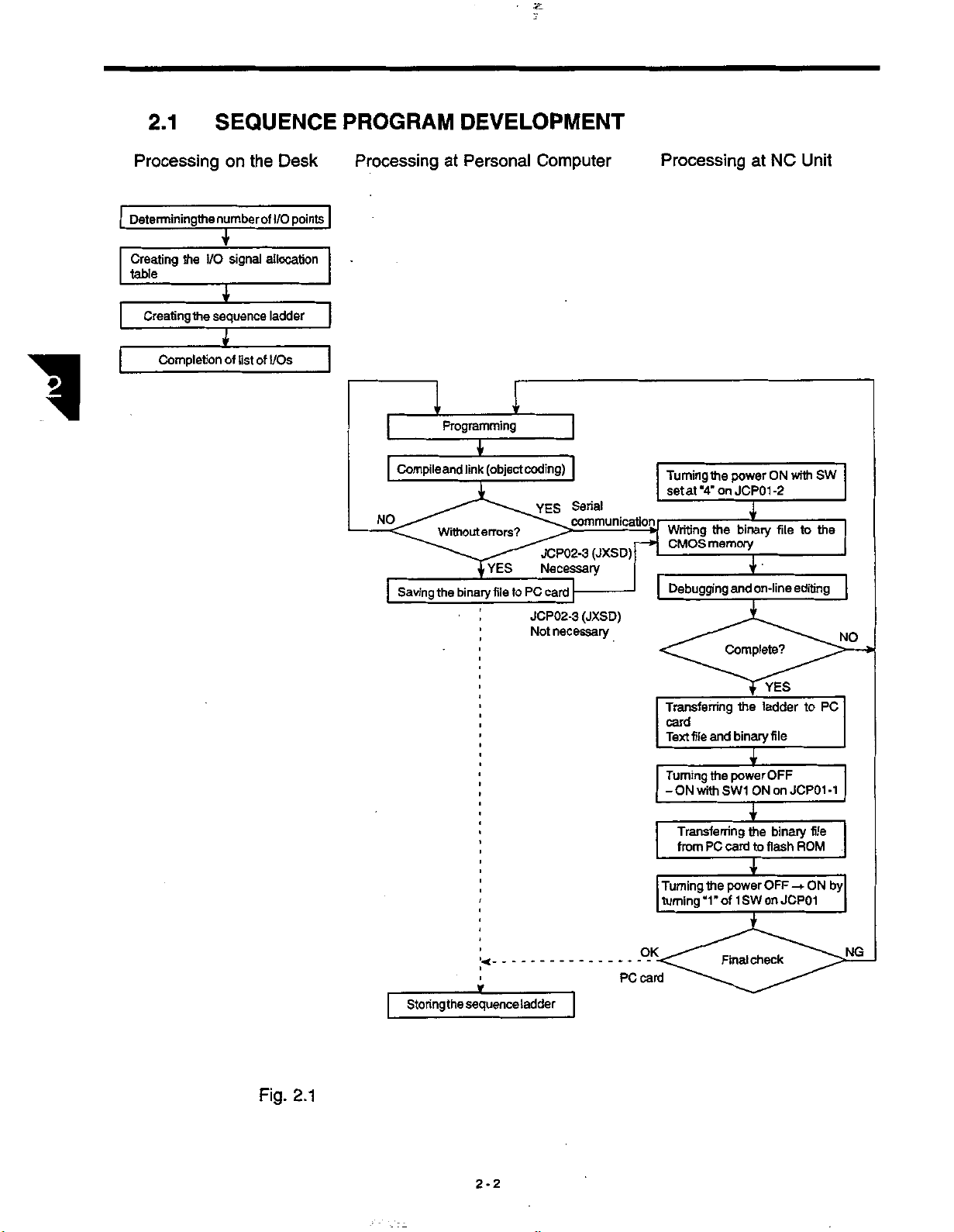
2.1
SEQUENCE
PROGRAM
DEVELOPMENT
1
Processing
Determiningthe
Creating
table
the
Creating
Completion
I/O
the
on
the
numberof
T
signal
I
sequence
I
of
list
Desk
I/O
points
allocation
ladder
of
I/Os
Processing
Compile
NO
Saving
Personal
at
Programming
I
(object
link
and
errors?
Without
YES
binary
file
the
Computer
'f
coding)
YES
JCP02-3
Necessary
card
PC
to
JCP02-3
necessary
Not
Serial
communication
(JXSD)
(JXSD)
Processing
Turning
setat“4’on
Writing
CMOS
Debugging
power
the
JCP01-2
the
memory
and
Complete?
at
T
binary
£
on-line
NC
ON
file
Unit
with
to
editing
SW
the
NO
Fig.
2.1
Storing
jr
sequence
the
ladder
PC
Transferring
card
Text
Turning
-
Turning
turning
OK
card
file
and
power
the
SW1
ON
with
Transferring
from
PC
card
power
the
“1”
of1SW
Final
the
binary
I
ON
I
the
to
T
check
YES
ladder
file
OFF
on
binary
flash
OFF
on
JCP01
to
JCP01
file
ROM
ON
-+
PC
-1
by
NG
2-2
Page 13
3
PLC
PROGRAM
Chapter
3.1
3.2
3.3
describes
3
BASIC
PROGRAM
INPUT/OUTPUT
SPECIFICATIONS
FUNCTIONS
SPECIFICATIONS
programs.
specifications
the
SPECIFICATIONS
of
PLC
....
3-2
3-3
-
3
4
¥
3-1
Page 14

3.1
BASIC
SPECIFICATIONS
1
Control
Processing
method
High-speed
Low-speed
Note:
Program
Instructions
memory
Basic
Program
Table
Note:
Basic
time
Value
symbol
128K
instruction
The
processing
processing
”n”
capacity
bytes
basic
specifications
time
scan
time
scan
determinedbythe
is
are
equivalent
of
to
approximately
programs
PLC
Scanning
0.5
4
ms
ms
4
high-speed
256K
128K
128K
61
fis/step
x
processing
bytes
bytes
bytes
kinds
indicated
are
method
(approximate
n
32K
steps
below.
value)
capacity
of
basic
total
and
instructions.
program
capacity.
Macro
instruction
22
kinds
3-2
Page 15

PROGRAM
3.2
FUNCTIONS
3.2
Internal
Registers
Timers
Sequence
Keep
Battery
relays
8
50
100
1
1
relays
back-up
PROGRAM
to
msec
255
to
to
memory
2.4
to
to
255
12.75
msec
msec
sec
min
parameters
sec
25.5
sec
min
FUNCTIONS
sec
sec
11960
1495
timers
188
timers
40
timers
60
timers
60
timers
20
timers
8
100
sets
7200
2900
points
registers
(5
bits/set)
(8
points
sets
(8
bits/register)
types)
l
&
1
.
Internal
internal
ters
Keep
2.
dresses
the
that
relays
relays
cannot
addresses
the
relays
used
keep
be
and
for
used
registers
and
cannot
used
battery
keep
for
registers
be
used
internal
for
back-up
relays
battery
(#8000
occupy
registers.
for
relays.
memory
cannot
back-up
#9999)
to
the
be
same
used
memoiy
cannot
addresses
Similarly,
occupy
battery
for
cannot
be
the
the
same
back-up
be
used
and
the
addresses
addresses,
memory.
used
for
the
for
addresses
for
used
and
Similarly,
relays.
keep
relays.
keep
used
regis¬
the
Note
for
ad¬
I
3-3
Page 16

3.3
INPUT/OUTPUT
SPECIFICATIONS
General-purpose
FC860,
The
FC861)
number
Module
FC810,
FC861
JSP02
An
input/output
panel.
boards
FC861
input:
and
I/O
of
JANCD-
FC860
Therefore,
(max.
input:
is
added,
points)
560
input/output
the
JSP
board
each
points
port
on
Number
Points
is
incorporated
modules
if
512
addition
is
possible.
112
64
64
points;
of
installed
are
ports
(JSP02)
module
of
Input
Number
the
in
FC810/FC860
max.
output:
maximum
a
the
in
indicated
is
Points
control
are
of
9
on
NC
of
Output
96
56
56
added,
440
boards
the
I/O
operation
below.
(JSP02)
board
addition
points)
(max.
module
panel.
machine
For
in
is
possible,
input:
(JANCD-FC810,
Remark
operation
NC
of
the
a
640
operation
maximum
and
if
points,
panel
4
of
module
max.
3-4
Page 17
4
SEQUENCE
Chapter
Sequence
ware,
which
in
characteristic,
erably
sing.
understood.
4.1
4.2
describes
4
control
which
When
DIFFERENCES
LEVEL
OF
differs
processing
different
developing
SEQUENCE
CONTROL
sequence
PLC
by
from
is
sequence
the
operation
AND
the
is
executed
ordinary
the
executed
control
from
programs,
IN
OPERATION
OPERATION
PROGRAM
control
sequentially
control
simultaneously.
by
ordinary
this
METHOD
method.
by
the
soft¬
by
resultsinconsid¬
PLC
relay
circuit
be
must
circuits
relay
Duetothis
proces¬
completely
4-2
4-3
f
RELATIONSHIP
4.3
THE
LADDER
AND
SEQUENCE
4.4
THE
CAPACITY
CONFIGURATION
4-1
BETWEEN
STOP
SEQUENCE
PROGRAM
AND
COUNT
MEMORY
!'
TASK
MEMORY
4-6
4-7
Page 18
4.1
DIFFERENCES
are
There
sequence.
two
types
OPERATION
IN
operation
of
modes
in
the
sequence
control
-
relay
sequence
and
PLC
1
(1)
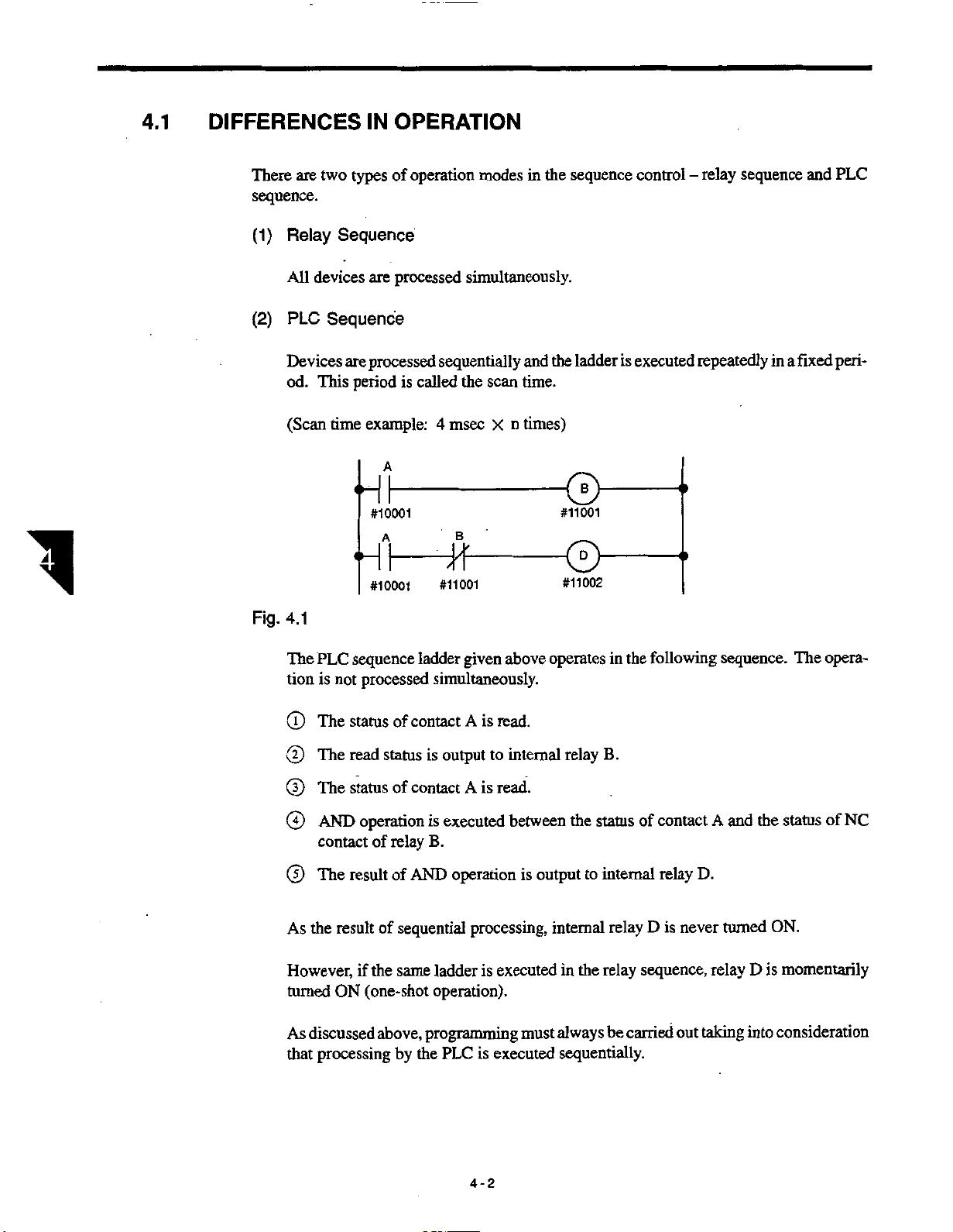
(2)
Fig.
Relay
All
devices
Sequence
PLC
Devices
od.
This
(Scan
time
4.1
PLC
The
tion
is
Sequence
are
processed
processed
are
period
example:
A
#10001
A
#10001
sequence
processed
not
simultaneously.
sequentially
called
4
msec
the
B
is
-
#11001
ladder
given
simultaneously.
scan
n
X
above
the
and
time.
times)
operates
ladder
©
#11001
®
#11002
is
executed
in
the
repeatedly
following
a
in
sequence.
fixed
The
peri¬
opera¬
The
©
The
©
The
©
AND
©
contact
The
©
the
As
However,
turned
As
that
result
ON
discussed
processing
contact
of
status
read
statusofcontact
operation
of
result
the
if
(one-shot
is
status
is
B.
relay
of
AND
sequential
of
same
above,
programming
the
by
ladder
operation).
PLC
is
A
read.
output
executed
to
is
read.
A
operation
processing,
executed
is
executed
is
internal
between
is
output
internal
always
must
B.
relay
status
internal
relay
relay
carried
be
of
D
sequence,
in
the
to
the
sequentially.
contact
relay
never
is
out
A
D.
turned
relay
taking
and
the
status
ON.
momentarily
is
D
into
consideration
of
NC
4-2
Page 19

4.2
LEVEL
AND
OPERATION
SEQUENCE
OF
PROGRAM
4.2
\
LEVEL
Length
scan
This
speed
be
AND
time
of
time.
High-speed
•
Low-speed
•
means,
processing
written
OPERATION
necessary
The
with
the
in
LD#
:
:
6TH1,
;
sm
scan
this
part
format
for
of
time
processing
processing
the
PLC,
and
low-speed
indicated
High-speed
End
Low-speed
End
SEQUENCE
OF
execution
the
this
model
scan
scan
sequence
processing
below.
processing
instruction
processing
instruction
of
PLC
of
time:
time:
program
high-speed
ot
sequence
of
one
4
msec
msec
4
part.
part
part
is
cycle
of
indicated
X
be
can
processed
Therefore,
processing
program
PROGRAM
a
sequence
below.
n
dividing
by
the
sequence
program
is
called
into
a
it
program
the
high¬
must
Fig.
4.2
indicated
As
tered
be
entered
Operation
(3)
The
4.3
Fig.
first
and
after
operation
NC
I/O
High-speed
Low-speed
Service
Processing
/
User’s
(
I/O
{
Background
V
above,
the
that.
Time
processing
processing
task
message
signal
the
sequence
sequence
Chart
chart
time
ladder
ladder
for:
display
display
processing
program
program
sequence
of
a
\
\
|
J
for
i
4=L
4
ms
that
which
program
i
r-i
-
i
:
requires
low-speed
I
I
—
high-speed
processing
is
indicated
-
I
I
—
n
i=L
i=i
processing
is
acceptable
below.
i
r-i
should
i
1
|
be
en¬
should
¥
4-3
Page 20

(a)
High-speed
The
gram
time
processing
high-speed
the
to
up
chart
RTH
above.
processing
instruction,
sequence
sequence
program,
is
executed
program
from
once
the
every
beginning
msec
or
4
the
of
less
sequence
showninthe
as
pro¬
1
During
changed.
Low-speed
(b)
The
divided
in
executed
As
speed
Since
input
in
Reading
(c)
At
lectively.
(d)
Outputting
processing
the
low-speed
into
each
4-msec
once
above,
seen
processing
the
low-speed
status
(3)
item
the
the
beginning
processing
processing
“n”
sections
interval.
“4
msec
in
value
program
processing
changed
be
will
below
must
input
of
the
the
output
of
“n”
always
state
4-msec
the
status
high-speed
sequence
sequence
one
is,
n”.
be
sequence
during
be
interval,
of
smaller
its
observed.
and
That
X
will
capacity
sequence
program
program
these
sections
the
low-speed
as
smaller.
are
program
execution.
the
status
program,
entered
the
total
is
Therefore,
of
the
input
following
is
executedinthe
processing
program
executed
all
inputs
in
the
is
status
the
RTH
instruction
remaining
sequence
capacity
several
and
sections,
precautions
read
into
the
remains
program
the
high¬
indicated
PLC
un¬
is
time
is
the
col¬
At
ly.
(4)
Precautions
The
response
Therefore,
less
(5)
Precautions
(T)
the
beginning
high-speed
is
required,
this
than
1000
time
Scan
capacity
The
sequence
mately
cessing
3000
sequence
of
the
High-speed
on
processing
such
should
when
steps
Low-speed
on
the
of
low-speed
the
sequence
of
program
steps
4-msec
sequence
counting
as
limited
be
converted
program.
size
contact
in
program
intervals,
the
Processing
program
the
only
to
the
into
the
Processing
processing
It
that
can
be
instructions.
and
low-
speed
previous
Sequence
only
treats
contact
ON/OFF.
requisite
contact
Sequence
sequence
is
calculated
processed
This
processing
output
status
Program
the
portion
program.
instructions.
Program
program
in
size
is
by
“4
4-msec
a
is
the
sequence
msec
total
is
output
where
capacity
The
influenced
n”.
x
interval
of
high-speed
program.
collective¬
high-speed
be
must
total
the
by
is
approxi¬
pro¬
4-4
Page 21

4.2
LEVEL
OPERATION
AND
SEQUENCE
OF
PROGRAM
Fig.
the
Since
©
the
status
fore,
the
quence
program
processing
sequence
shouldbeused
High-speedprocessing
Low-speed
4.4
creating
By
quence
program
low-speed
inputs
of
inputs
that
should
sequence
program,
the
as
processing
the
program
can
processing
will
be
changed
used
are
taken
be
program,
the
contacts
signals.
input
in
executed
be
program
program
this
sequence
sequence
sequence
during
for
the
into
the
for
and
of
the
manner,
under
is
program
the
executedinseveral
executionofthe
executionofthe
internal
the
relays
one
the
relays
executionofthe
where
the
shouldbetaken
relays.
of
cycle
same
the
input
low-speed
the
at
start
low-speed
have
inputs
low-speed
status.
signal
program.
processing
of
the
low-speed
processing
been
.
ieed
into
the
processing
sections,
There¬
se¬
received
ogram
internal
se¬
Fig.
(D
©
the
resultsofthe
If
processing
speed
creation
The
signals
program
ternal
outputs.
of
the
that
is
executed
program.
shouldbeconnectedtothe
processing
sequence
RTH
4.5
high-speed
sequence
should
not
should
Such
signals
program.
•
Write
—
execution
programatthis
processing
program,
be
output
be
not
should
external
outputs
the
one
of
the
until
directly
first
output
that
cycle
part
sequence
consideration
same
cycle
one
to
output
be
input
addressesatthe
should
of
the
output
be
low-speed
program
the
of
the
PLC
the
internal
to
externally
processing
are
output
be
must
given
low-speed
address
used
relays
the
of
end
the
after
sequence
the
low-
to
the
to
processing
ex¬
for
and
they
low-speed
F
4-5
Page 22

4.3
RELATIONSHIP
BETWEEN
THE
LADDER
STOP
COUNT
AND
THE
1
SEQUENCE
The
service
User’s
•
I/O
•
Background
•
Others
•
task
The
cessing
The
stopped)
Recommended
operates
sequence
ladder
should
TASK
task
includes
message
signal
during
program
count
stop
be
value:
the
display
display
processing
the
and
(the
based
set
1
following:
processing
processing
until
the
from
the
of
load
period,
number
on
completion
the
of
start
times
during
the
next
the
low-speed
the
processing
one
of
scan.
processing
scan
of
the
the
of
ladder
service
low-speed
should
task.
pro¬
be
4-6
Page 23

4.4SEQUENCE
PROGRAM
MEMORY
CAPACITY
AND
MEMORY
CONFIGURATION
4.4
SEQUENCE
PROGRAM
CONFIGURATION
The
The
sequence
program
program
memory
128K
bytes
>
bytes
128K
is
of
finally
this
PLC
High-speed
Low-speed
MEMORY
the
written
to
can
Message
divided
be
Controllable
Processing
Processing
Data
Table
Table
CAPACITY
flash
memory
into
the
areas
Program
Program
AND
(ROM).
indicated
MEMORY
below.
Fig.
4.6
Generally,
that
32K
one
steps
ing
to
relay
instructions
instruction
(128K/4
occupy
occupies
K).
32
=
3
an
average
to
bytes
7
of
and
bytes,
4
other
128K
instructions
byte
memory
¥
25
bytes.
to
1
area
Assum¬
equivalent
is
4-7
Page 24

Page 25

5
ADDRESS
NUMBERS
Chapter
5.1
5.2
5
describes
ADDRESS
ADDRESS
SYMBOLS
AND
the
MAP
MAP
ADDRESS
address
AND
numbers
DISPLAY
and
MAP
address
map.
5-2
5-3
E
5-1
i
Page 26
5.1
ADDRESS
MAP
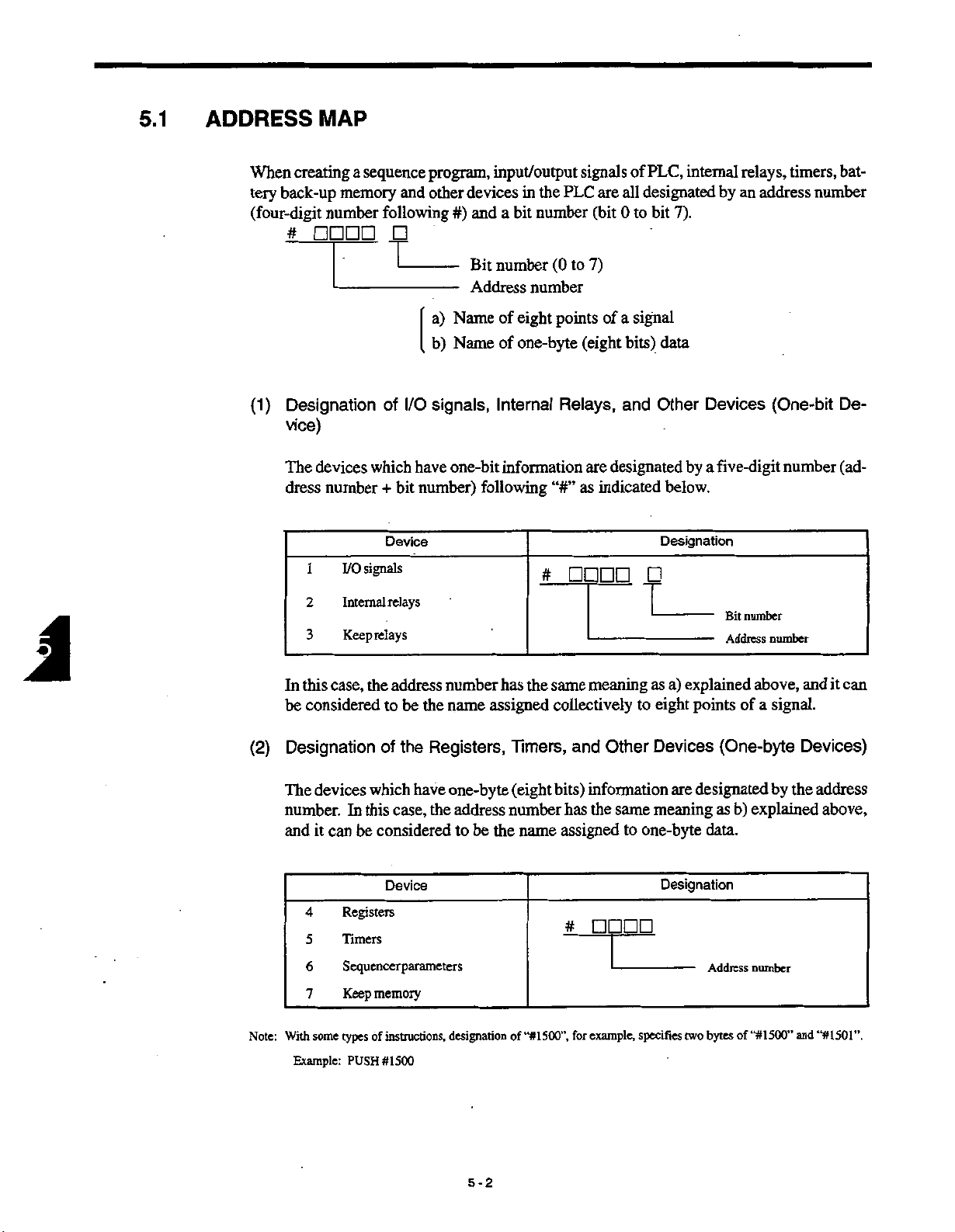
When
creating
back-up
tery
(four-digit
#
Designation
(1)
vice)
The
dress
1
2
3
a
sequence
memory
number
following
of
devices
which
number+bit
I/O
signals
Internal
Keeprelays
and
T
I/O
Device
relays
program,
other
#)
-
-
a)
Name
b)
Name
signals,
one-bit
have
number)
input/output
devices
bit
and
a
number
Bit
Address
of
eight
of
one-byte
Internal
information
following
the
in
number
(0
number
points
“#”
#
signals
PLC
are
(bit
7)
to
of
(eight
Relays,
are
indicated
as
PLC,
of
designated
all
7).
bit
0
to
signal
a
bits)
data
and
Other
designated
below.
Designation
T
internal
by
Devices
by
a
five-digit
Bit
Address
relays,
address
an
(One-bit
number
number
timers,
number
number
bat¬
De¬
(ad¬
In
be
Designation
(2)
The
number.
and
With
Note:
Example:
the
case,
this
considered
address
to
of
devices
it
4
5
6
7
some
which
this
considered
be
Device
memory
instructions,
of
#1500
PUSH
case,
In
can
Registers
Timers
Sequencerparameters
Keep
types
the
be
the
Registers,
have
the
number
assigned
name
one-byte
address
the
be
to
designation
has
the
Timers,
(eight
number
name
“#1500”,
of
same
meaning
as
a)
collectivelytoeight
and
bits)
information
the
has
assigned
#
example,
for
Other
same
to
one-byte
specifies
Devices
are
meaning
Designation
explained
points
of
(One-byte
designated
b)
as
data.
Address
of
bytes
two
a
signal.
and
above,
Devices)
the
by
explained
number
and
“#1500”
can
it
address
above,
“#1501”.
5-2
Page 27

ADDRESS
5.2
MAP
AND
DISPLAY
SYMBOLS
5.2
ADDRESS
The
address
Standard
(1)
Addresses
MAP
map
K>-
te)
AND
and
the
NC
MEM
#7100
#9999
of
Section
beck-up
t
—
—
Input
Main
(Example)
Hi¬
Batteryÿ
memory
pm7000
Jjm7099
DISPLAY
relationship
PLC
Output
Input
-
-
Signals
(4)
outputs!
NC
#3000
die
inputs
NC
#3500
#3699
-
0)
Sequencer
*s
parameters
pm
7000
(11)
(10)
-#7999
sJ
Keep
#7100
|
-#9999
I
memory
from
SYMBOLS
external
with
Section
<1)
in#
Mach
inputs
#1000
•#1063
(21
outputs
Machine
#1100
I
-#1163
I
relays
Internal
registers
end
8'
#1200
•#2994
l
-#1399
#1700
|
-#1799
I
the
Machine
devices
i/O
Section
Input
Output
f
I
(#1000
are
shown
Machine
(Ex.)
-Wh
LS
SOL
to
#1063)
below.
the
those
signals
of
pushbutton
The
For
as
signed.
minedbythe
bit
One
©
Address
©
the
connector
Example:
#1000,
The
©
input
from
input
the
switches
tool
(#
between
builder.
1000s)
number
bit
correspondence
machine
address
of
number
and
numberofthe
54-5
54-21
64-36
Pin
II
signals
(NO
Connector
Enter
of
#1000s
#10000
contact)
No.
the
machine
limit
and
the
corresponds
are
board
I/O
54-35
54-20
10
No.
01
signal
input
are
expressed
operation
switches,
address
to
determined
where
_
2
54-34
name.
by
;
and
panel
addresses
and
the
one
point
depending
the
input
1
54-33
54-19
the
following
m-
(NC
electric
input
of
input
signal
0
#10DOO
contact)
control
#1000
signal
signals.
the
on
is
symbols.
panel,
#1063
to
should
pin
are
deter¬
be
number
connected.
such
as¬
and
5-3
Page 28

(2)
Addresses
For
the
as
respondence
chine
signals
the
signals
tool
Output
of
output
of
lamps
between
builder.
Signals
the
to
and
the
address
the
to
machine
solenoids,
and
Machine
operation
addresses
the
output
#1163)
and
to
electric
(#1100
panel
#1100to#1163are
should
signal
be
determined
control
panel,
assigned.
by
The
the
such
cor¬
ma¬
J
©
©
Example:
(D
(3)
Addresses
For
the
assigned.
bit
One
Address
the
connector
The
output
the
signals
main
NC
address
of
number
(#1
and
number
#1100
/I51-5
signals
Input
input
Signals
from
of
sectiontothe
100s)
bit
of
,
-
7
of
#1100s
#nonn
the
PLC,
corresponds
number
I/O
the
No.
Bit
fi
51-7
51-6
I
Pin
No.
Connector
the
Enter
are
the
from
main
NC
such
to
determined
are
where
board
5
£1-41
151-8
10
No.
08
signal
output
expressed
NC’s
section,
M-BCD
as
one
depending
the
3
lsi
name.
the
by
#•
(NO
Main
other
in
signal,
of
point
output
2
151-26
-27
following
11DDO
contact)
Section
words,
addresses
on
Q
signals.
the
pin
is
connected.
output
signal
151-25
symbols.
#naoo
contact)
(NC
(#3500
signals
the
#3500to#3799
number
#3799)
to
output
and
from
are
The
correspondence
and
©
cannot
One
be
bitofaddress
Example:
between
changed.
#3520
|
MA7
(#3500
7
|
6
MA6
5-4
the
to
Bit
signal
#3799)
No.
3
MA5
[
name
and
corresponds
4
MA3
MA4
|
|
M
First
code
the
3
output
address
to
one
2
MA2
|
is
determined
pointofinput
|
MAO
|
MA1
by
the
NC
signals.
0
|
Page 29

(D
The
input
signals
#3500to#3799
of
5.2
are
expressed
ADDRESS
by
MAP
AND
following
the
DISPLAY
symbols.
SYMBOLS
(4)
Addresses
For
mode
The
and
(T)
Example:
(D
of
Output
the
signals
selection
output
signals,
correspondence
be
of
bit
#3000
output
changed.
address
|
signals
Output
cannot
One
The
#3nnnn
Signals
from
the
to
PLC
addresses
between
(#3000to#3159)
7
EDT|MEM
Edit
Memory
of
to
the
Bit
€
#3000
NC
the
signal
No.
|
Manual
to
(a)
NC
the
to
Main
theNCmain
#3000to#3159
and
name
corresponds
4
5
MDI
#3159
:
-
TP
j
Tape
Q
#3onnn
3
STP
j
Step
are
expressed
—
(b)
-
if
#3nncn
Section
section,
are
the
|
Handle
(#3000
such
assigned.
addressisdetermined
one
to
point
2
1
JOG
H
|
Jog
the
by
following
[
to
as
EDIT
of
0
RT
Rapid
#3159)
output
|
symbols.
and
MEM
the
by
signals.
NC
E
5-5
#3DODD
1
#3nonn
j
Page 30

(5)
Addresses
#1700
#1799)
to
Internal
of
Relays
(#1
200
#2994;
to
excluding
#1
300
to
#1
399
and
For
the
internal
addresses
signed.
One
©
relay.
Example
number
The
©
500
bytes
(3)
The
internal
that
relays
#1200to#2994
bitofaddress
I/O
list:
of
7
#1400
[
usable
of
8
bits
X
relay
Internal
can
(excluding
#1400s,
of
I
internal
4000
=
its
and
relay
be
Bit
6
Enter
contact
:
--
used
for
No.
5
1
an
relays
relays
#140DD
in
PLC
only
the
#1300to#1399
example,
4
corresponds
3
1
interna)
are
name.
relay
indicated
is
expressed
—
to
and
2
below.
by
the
a
create
#1700
one
to
following
sequence
#1799)
to
of
piece
0
]
symbol.
program,
as¬
are
internal
©
There
are
program
The
addresses
limitstothe
no
capacity
used
is
not
for
#14DOO
contact)
(NO
number
exceeded.
registers
5-6
of
contacts
cannot
#140DD
contact)
(NC
be
(NO
used
and
for
contacts)
NC
internal
relays.
as
long
as
the
Page 31

5.2
ADDRESS
MAP
AND
DISPLAY
SYMBOLS
(6)
Addresses
#1700
For
cluding
These
instructions.
®
®
(D
of
Registers
#1799)
to
the
general-purpose
#1300
registers
One
Example
The
#1300
For
to
address
of
#1500
#1501
number
#1399
to
the
registers,
are
I/O
#1399
used
number
list:
[
usable
of
and
the
(#1200
one-byte
and
for
(eight
#1700
register
to
corresponds
Enter
a
register
registers
#1799).
#1700
to
address
number
#2994;
to
bits)
register,
#1799)
are
instructions
a
one-byte
to
name.
the
is
in
range
itself
excluding
addresses
assigned.
and
workpiece
register.
from
is
used
as
#1300
#1200
symbol
the
to
#1200
address
#2994
to
to
in
#1399
#2994
for
(excludes
ladder.
a
and
(ex¬
macro
®
the
See
addresses
The
examples
used
below.
for
internal
t
relays
#isnn
Register
#15DD
Macro
instruction
cannot
}
instruction
(example:
be
used
(example:
for
INR)
PUSH)
registers.
5-7
Page 32

(7)
Addresses
Timers
of
(#1
300
to
#1
399
and
#1
700
to
#1
799)
J
Table
For
©
©
5.1
timers,
the
address
One
Example
#1700
#1701
number
The
#1700
#1300
#1710
#1310
#1730
#1330
addresses
number
list:
I/O
of
of
available
Address
#1760
#1709,
to
to
#1309,
#1360
#1729,
to
to
to
to
#1750
#1350
#1770
#1370to#1373
#1329,
#1749,
#1349,
#1790
#1390
#1780
#1380
#1759
to
#1359
to
to
#1773
#1300
to
#1399
corresponds
timer
Entera
timers
No.
#1769
to
#1369
to
#1799
to
#1399
to
#1789
to
#1389
to
to
and
and
a
timer.
name.
timer
#1700
TtmerType
1
setting
8
1
msec
=
=0.1
1
50
msec
=
sec
1
1
=
1
1
min
=
to
units
sec
#1799
Enter
are
are
assigned.
setting
a
value.
indicated
Number
below.
of
Timers
40
60
60
20
8
An
©
(Example)
example
of
timer
a
-0D-
symbol
-L
Timer
types)
(2
5-8
indicated
is
#170D
instruction
below.
ODH
Do-
Timersettingvalue
(hexadecimal)
Page 33

ADDRESS
5.2
MAP
AND
DISPLAY
SYMBOLS
{8)
Battery
For
the
“battery
tained
even
PLC
the
In
dled.Itis
The
battery
Sequencer
•
Keep
•
Keep
•
Back-up
memory
back-up
when
sequence
possible
not
back-up
relays:
memory:
Standard
Battery
Memory
which
to
addresses
memory”.
the
power
ladder
handle
to
memory
parameters:
Main
NC
back-up
pm
7000
to
7099
pm
#7100
to
#9999
(pm7000
of
#7000s
The
data
is
turned
program,
data
(read
are
OFF.
only
and
pm7000
#7100to#7999
#7100
Section
to
I
memory
to
pm7099,
are
savedtothis
image
the
write)
the
classified
to
#9999
PLC
pm
Keep
#71
Keep
#71
into
pm7099
Section
(Image)
Sequencer
parameters
7000
pm
to
relays
00
#7999
to
memory
#9999
to
00
#7100
assigned,
of
type
dataatthe
source
following
the
7099
#9999)
to
such
memory
memory
PLC
datainthe
are
side
NC
three
called
is
therefore
be
can
main
section.
types.
the
re¬
han¬
E
(a)
Transferring
The
the
If
the
In
attempt
sequencer
following
even
one
entire
sequencer
a
sequence
to
the
parameter
case
item
of
program,
change
sequencer
data
addition
in
sequencer
parameter
is
allowed
it
the
data.
5-9
parameter
transferred
are
time
the
to
parameter
are
data
only
to
data
from
the
when
changed
is
data
transferred
the
read
to
fi
PLC
the
theNCmain
is
power
turned
by
parameter
collectively.
sequencer
section
ON.
write
parameter
the
PLC
to
operation,
Do
data.
in
not
Page 34

Transferring
(b)
the
data
in
the
keep
relay
and
keep
memory
data
to
the
NC
A
Image
ously
fore,
memory
matic
While
the
(9)
Addresses
For
for
tion.
When
methods
Using
(a)
Example
data
since
it
necessary
is
the
in
data
transfer.
the
power
PLC
to
the
sequencer
sequencer
using
are
To
use
•
To
use
•
as
one-bit
of
in
saved
the
data
main
NC
is
the
NC.
of
Sequencer
parameters,
parameters
data
the
available.
one-bit
as
one-byte
as
data
list:
I/O
the
keep
read
are
transfer
to
section
ON,
these
of
data
data
relays
written
and
the
as
the
data
in
Parameters
addresses
changed
be
can
parameters
and
latest
the
source
#7100
keep
the
the
as
sequence
data
image
data.
to
#9999
(pm7000
pm7000
using
by
a
sequence
in
memory
the
in
data
This
are
to
pm7099
to
the
normal
in
PLC
the
to
is
the
program
PLC
transfer
collectively
pm7099)
assigned.
are
parameter
parameter,
change
executed.
battery
called
is
transferred
The
write
the
following
continu¬
There¬
back-up
auto¬
the
from
data
set
opera¬
two
The
symbol
pm7000
used
in
No.
Sit
i
4
5
6
7
[
the
1.1
ladder
is
I
Entarsignal
indicated
I
name.
below.
2
3
I I
0
I
if
pm
pm70DDD
T
Data
Data
“0”
Closed
=
Open
=
“1*
Data
Data
“0*=Closed
70000
Open
=
5-10
Page 35

Usingasone-byte
(b)
data
ADDRESS
5.2
MAP
AND
DISPLAY
SYMBOLS
Example
In
See
(10)
For
0
of
this
case,
the
example
Addresses
the
keep
bit
One
list:
I/O
pm7000
pm7001
1
)
t
the
address
below
[HI-TT
Keep
of
relays
corresponds
Relays
that
number
where
Variable
instruction
can
to
parameter
Enter
is
itself
a
parameter
#1770,
timer
used
is
pm
7
pD-O-l
parameter
a
(#7100to#7999)
usedinthe
be
one
pieceofkeep
PLC,
data
setting
name.
the
as
used
address
relay.
symbol.
timer
a
with
by
#7100to#7999
]
]
instruction.
are
assigned.
k
©
©
Example
The
900
Keep
of
I/O
#7101
numberofusable
bytes
x
relays
[
8
and
Keep
list:
f
7
-
bits
=
contacts
relay
Bit
6
Enter
keep
7200
are
:
No.
5
keep
relays
relays
expressed
#71DOO
#71DDO
(a)
4
f
relay
name.
indicated
is
by
''
#71DDD
(b)
3
below.
the
following
2
0
symbol.
5-11
Page 36

(11)
Addresses
For
es
the
Therefore,
ry
one-byte
the
#7100
saved
of
data
of
to
#9999
data,
the
keep
macro
Memory
Keep
memory
keep
assigned.
are
it
can
used
be
memory
instructions.
where
in
can
(#7100
the
With
the
same
usedasthe
be
#9999)
to
data
the
exception
maimer
retained
can
be
the
that
with
the
as
objectofregister
after
power
memory
keep
registers.
instructions
OFF,
can
or
address¬
retain
auxilia¬
When
be
used.
0
0
0
writing
For
one-byte
Example
#7105
#7106
The
number
2900
in
For
the
keep
See
the
example
a
sequence
bits)
(8
I/O
list:
of
tr
usable
of
the
range
memory,
below.
HH
Contents
MOV:
to
program
keep
keep
from
the
MOV
memory
keep
memory,
Enter
#7100
address
#1500,
1
register
of
random
for
keep
memory
memory
#9999
to
number
#7100
500
#1
#71
type
address
name.
is:
itself
H
are
transferred
ATC
memory,
number
is
used
#7100
]
as
a
or
the
keep
memory
is
above
symbol.
must
assigned.
5-12
Page 37

ADDRESS
5.2
MAP
AND
DISPLAY
SYMBOLS
For
the
0
ber
devices
is
assigned.
Although
two-byte
as
the
case
In
dress;the
data.
byte
Byte
#7200 #7200
#7201
#7202
#7203
that
the
data
or
four-byte
of
two-
address
Word
start
Double-word
Setting
pm3430<pm3431
have
are
four-byte
or
of
the
number
start
range:
one-byte
basically
data
by
significant
least
Word
#7202
setting
number
to
8000
or
larger
one-byte
of
the
setting
data,
the
parameter
setting
parameter:
9999
information,
construction,
the
for
address
used
is
byte
parameter.
is
specified
the
as
pm3430
pm3431
four-digit
a
data
the
as
address
address
can
one-byte
a
for
two-
handled
be
unit
or
num¬
ad¬
four-
(12)
Writing
When
the
set
the
Set
Set
©
Press
©
Move
©
Use
after
Byte
#8200
#8201
#8203
the
keep
initial
initial
the
the
keying
Initial
relays
values
system
the
the
page
Values
and
for
following
values
number
[MAINT]
cursor
keys
in
the
keep
these
process
the
to
and
keep
Word
#8200
#8202#8202
Keep
for
memory
devices
the
switch
key
required
the
cursor
memory
Relays
used
are
before
procedure
NC
the
in
the
and
memory
keep
up/down
number.
Double-word
#8200
Keep
and
a
in
sequence
to
the
below.
“1”
running
indicted
unit
[SEQPRM]
number.
keys,
or
press
Memory
program,
program.
turn
and
function
the
cursor
necessary
it
is
the
power
soft-key.
up/down
E
to
ON.
keys
5-13
Page 38

0
Press
the
[INSRT]
key
or
the
cursor
right
key.
Cursor
Move
®
[WRITE]
Each
changed.
Data
mal
Example:
[INSRT]
the
time
entry
number
Key
[WRITE]
[0]
[WRITE]
[8]
[5]
[2]
key:
right
cursor
key.
[5]
The
key:
[WRITE]
the
by
numeric
column.
Writing
Operation
[WRITE]
PARAMETER
cursor
The
the
to
decimal
a
#7100
|
I
moves
cursor
for
bit
key
is
keys
7
6
0
0
0
0
1
1
0
0
0
0
00000000
0 0
0
0
00000000
00000000
:OFF
0
PARM~|
PARM
ISETTINGI
I
to
moves
which
is
pressed,
possible
number
Bit
00000000
00001000
11111111
MNT
4
5
0
0
0
0
1
1
i
0
0
0
0
0
0
DIAGN.
ISEOPRÿ
the
to
7
6
3:
0
0
1 1
0
0
0
0
TIME
decimal
the
data
the
ON/OFF
only
bit
for
3
5
4
O*****
2
0
0 0
0
0
0
0
0
1
:
I
P»ERRI
bit
when
data
2
1
0
1 1
0
0
0
0
ON
number
data
should
0
1
0
0
0
0
0
0 0
0
STP
I I
column.
be
status
cursor
the
N00000
0
8
255
0
0
0
0
0
LSK
T
(71
column.
changed
the
of
moved
is
Decimal
and
press
specified
to
the
Number
0
8
255
the
is
bit
deci¬
0
@
Repeat
Return
steps
the
@
and
system
to
©
number
5-14
write
switch
the
initial
to
“0”.
values
for
the
necessary
addresses.
Page 39

ea
6
Chapter
types
61
tions.
bols.
6.1
6.2
6.3
6.4
describes
6
basic
of
Explanation
The
list
BASICS
TYPES
INSTRUCTIONS
RELAY
TIMER
PLC
instructions
coded
of
OF
AND
INSTRUCTIONS
PLC
instructions.
and
for
the
instructions
INSTRUCTIONS
OF
is
PLC
the
given
LIST
....
INSTRUCTIONS
INSTRUCTIONS
11
types
functions
is
also
The
macro
of
and
given.
can
PLC
display
use
instruc¬
sym¬
6-2
6-3
6-8
6-15
REGISTER
6.5
CONTROL
6.6
MACRO
6.7
INSTRUCTIONS
INSTRUCTIONS
INSTRUCTIONS
i
\
6-1
6-17
6-41
6-44
Page 40

6.1
BASICS
OF
PLC
INSTRUCTIONS
(13)
(14)
Registers
PLC
The
program
Contact
Result
This
Setting
the
It
is
the
using
are
status
Register
one-bit
is
a
the
contents
also
possible
contents
the
Saving
has
saved.
the
registers
Configuration
Intermediate
where
The
result
_
I
|~RR][STO|ST1
status
of
of
STR
—
/U
L
STR.STR-NOT
(RR)
register
(0or1)
to
RR
to
shift
the
stack
or
AND-STR
\J
KJ
AND-STR,
where
of
relay
the
the
register
intermediate
the
of
operation
of
register
Stack
[
ST3
ST2
1
V_>
KJ
KJ
OR-STR
instruction,
result
the
contact
to
address
contents
RR
to
instruction.
Results
these
presently
ST4|sT5|
1
KJ
instruction,
etc.
RR
by
of
RR
by
results
registers
bits)
(1
6
KJ
of
presently
using
by
using
the
to
bit
one
during
516ÿ1
etc.
of
is
executed
Logical
logical
“1
is
operation
bit
+
saved
Operation
16
bits”.
).
or
(0
1
in
a
_
STISISTHIST-ISI
V_>
W
executed
the
LD
instruction
the
stack
after
OUT
register
the
instruction
completion
“O'
operation
and
are
by
bit
one
of
operation
is
outputting
possible.
or
sequence
set.
to
shift
by
(15)
Stack
When
the
to
The
STR
data
The
STO
bit.
STR
tions
error
an
and
the
register
executing
register
stack
and
STR-NOT
in
stack
the
AND-STR
RR,
and
After
and
must
set
the
execution
STR-NOT
the
be
occurs.
number
to
(STO
a
logical
long
by
up
registers
and
OR-STR
result
the
instructions,
same
during
other
In
data
fetching
of
ST15)
operation,
bits.
16
to
instructions
right
the
to
instructions
and
to
RR
instructions,
these
of
and
execution
the
words,
the
times
it
the
move
one
by
execute
the
shift
number
the
of
number
from
possible
is
data
bit.
data
“0”
is
of
series
a
data
of
stack
the
save
to
RR
to
in
the
operation
in
stack
for
set
ST15.
AND-STR
logical
of
saving
register
the
intermediate
and,
STO
between
register
Both
and
operations
times
to
must
sequentially,
the
the
to
left
number
the
OR-STR
the
the
be
instruc¬
Otherwise,
.
stack
register
same.
result
data
by
one
the
in
of
6-2
Page 41

6.2
TYPES
AND
UST
INSTRUCTIONS
OF
6.2
TYPES
(1)
(a)
(b)
(2)
No.
10
11
12
13
AND
Types
With
Basic
Relay
Register
Timer
Control
Macro
Macro
Auxiliary
List
The
1
2
3
4
5
6
7
8
9
LIST
Instructions
of
PLC,
the
instructions
instruction:
instruction:
instruction:
instruction:
instructions
instruction:
instruction:
Relay
of
list
relay
of
Instruction
LD
LD-NOT
AND
AND-NOT
OR
OR-NOT
XOR
XNR
STR
STR-NOT
AND-STR
OR-STR
OUT
INSTRUCTIONS
OF
following
the
13
37
2
9
22
5
types
types
types
types
types
types
types
Instructions
is
instructions
Reads
Reads
Executes
result
Executes
RR,
Executes
toRR.
Executes
and
Sets
Sets
Enters
the
Enters
the
Executes
the
Executes
result
Writes
signal
the
the
inversion
AND
to
RR.
AND
and
sets
OR
(Logical
OR
the
sets
“not-coincide”
“coincide”
content
the
LD
instruction.
the
content
LD-NOT
AND
result
to
OR
RR.
to
result
the
indicated
(0,
status
signal
of
between
(Logical
the
between
between
result
instruction.
RR.
betweenRRand
product)
between
result
to
the
sum)
the
RR.
to
between
between
of
RR
of
RR
between
operation
of
of
instructions
Total
below.
Description
1)
and
sets
status
the
contact
the
inversion
(Reverse
RR.
and
contact
inversion
(Reverse
the
to
to
RR
the
signal
the
the
and
(RR)
signal
stack
stack
the
the
logical
and
stack
to
61
to
it
(0,
1)
RR,
and
signal
of
logical
RR,
of
signal
and
RRtoRR.
register
register
stack
register
the
are
types
RR.
and
sets
and
status
product)
and
sets
status
sum)
RRtoRR.
and
and
register
(address).
relay
provided.
RR.
to
it
the
sets
and
the
result
RR,
and
executes
executes
and
sets
sets
the
and
RR
after
Operation
0
*
0
0
0
t
0
0
0
0
0
$
*
Note:
Symbol
The
0
The
—
the
in
content
content
column
of
RR
of
“RR
of
changes
RR
does
after
before
not
Operation”
and
after
change
before
6-3
operation
the
or
after
of
the
instruction.
an
operation
an
of
instruction.
Page 42
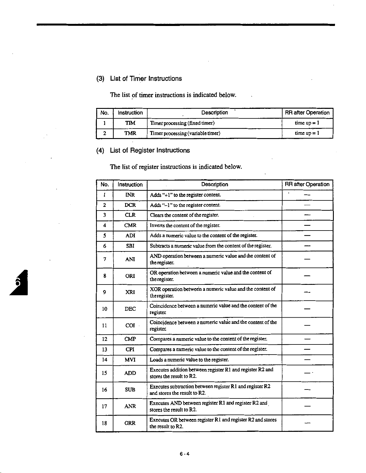
(3)
List
of
Timer
Instructions
(4)
No.
1
2
No.
1
2
3
4
5
6
7
8
9
10
11
12
13
14
15
16
17
18
The
List
Instruction
TMR
of
List
The
list
Instruction
CMR
DEC
CMP
MVI
ADD
ORR
of
timer
TIM
Register
of
register
INR
OCR
CLR
ADI
SBI
ANI
ORI
XRI
COI
CPI
SUB
ANR
instructions
processing
Timer
Timer
processing
Instructions
instructions
the
to
“+1”
Adds
the
to
“-1
Adds
Clears
Inverts
Addsanumeric
Subtracts
AND
the
OR
the
XOR
theregister.
Coincidence
register
Coincidence
register
Compares
Compares
Loadsanumeric
Executes
stores
Executes
and
Executes
stores
Executes
the
”
the
content
the
a
operation
register.
operation
register.
operation
a
a
addition
result
the
subtraction
the
stores
AND
the
result
OR
result
to
content
numeric
between
between
between
numeric
numeric
result
between
R2.
is
indicated
(fixed
(variable
indicated
is
register
register
the
of
the
of
value
to
value
between
a
between
a
a
value
value
valuetothe
between
R2.
to
between
to
R2.
between
to
R2.
register
below.
Description
timer)
timer)
Description
content.
content.
register.
register.
the
content
the
from
numeric
a
numeric
a
numeric
numeric
register
value
numeric
value
value
the
to
content
the
content
to
register.
register
registerRland
R1
and
R1
below.
the
of
content
and
value
and
value
and
and
and
of
of
and
R1
register
and
register
register.
the
register.
of
the
content
the
content
the
content
the
content
content
the
register.
the
register.
the
register
register
R2
R2
R2
and
R2
and
of
of
of
the
of
of
the
and
stores
RR
RR
after
time
time
after
Operation
1
up
=
up
1
=
Operation
6-4
Page 43

6.2
TYPES
AND
LIST
OF
INSTRUCTIONS
No.
19
20
21
22
23
24
25
26
27
28
29
30
31
32
33
Instruction
XRR
CPR
COR
MOV
DST
DIN
ADC
ADDW
SUBW
MULW
DIVW
INRW
DCRW
CLRW
CMRW
Executes
result
to
Executes
the
stores
Executes
the
stores
Transfers
Executes
register
the
Extracts
Executes
Executes
double-length
and
WR2.
Subtracts
the
content
result
to
Multiplies
the
content
result
to
Divides
tent
of
double-length
WR2.
Adds
“+I”
Adds
“-1
the
Clears
Inverts
the
XOR
between
R2.
comparison
RR.
result
to
comparison
“coincide”
the
content
between
AND
transfers
and
1
data.
double-length
addition
between
register
the
content
of
double-length
WR2.
the
content
double-length
of
WR2.
double-length
of
content
the
content
to
the
to
content
”
of
content
of
content
Description
registers
between
between
result
of
to
register
the
a
numeric
the
registers
registers
RR.
result
addition.
double-length
(WR1)
of
double-length
register
double-length
of
register
(WR2)
register
of
the
double-length
double-length
of
the
the
double-length
the
double-length
and
R1
R1
value
register
to
and
stores
register
(WR2)
(WR2)
register
and
and
R2
R1
andR2and
andR2and
R1
register
to
and
register
the
and
register
and
(WR1)
stores
register
register.
stores
R2.
the
content
R2.
(WR2)
result
(WR1)
stores
(WR1)
stores
by
the
result
register.
register.
to
“0”.
the
the
of
to
from
the
and
the
con¬
after
RR
Operation
0
0
$
is
set
RR
when
to
to
overflow
occurs.
0
“1”
l
34
35
36
37
CORW
CPRW
MVIW
DSTW
Executes
double-length
comparison
RR.
Executes
comparison
double-length
numeric
a
Loads
Executes
(WR1)
AND
andanumeric
double-length
register
register
valuetothe
between
register
6-5
between
and
R2
between
and
R2
double-length
the
content
and
value
(WR2).
double-length
the
stores
“coincide”
double-length
result
the
stores
register.
double-length
of
transfers
the
register
result
register
RR.
to
result
to
R1
and
to
and
R1
register
0
0
Page 44
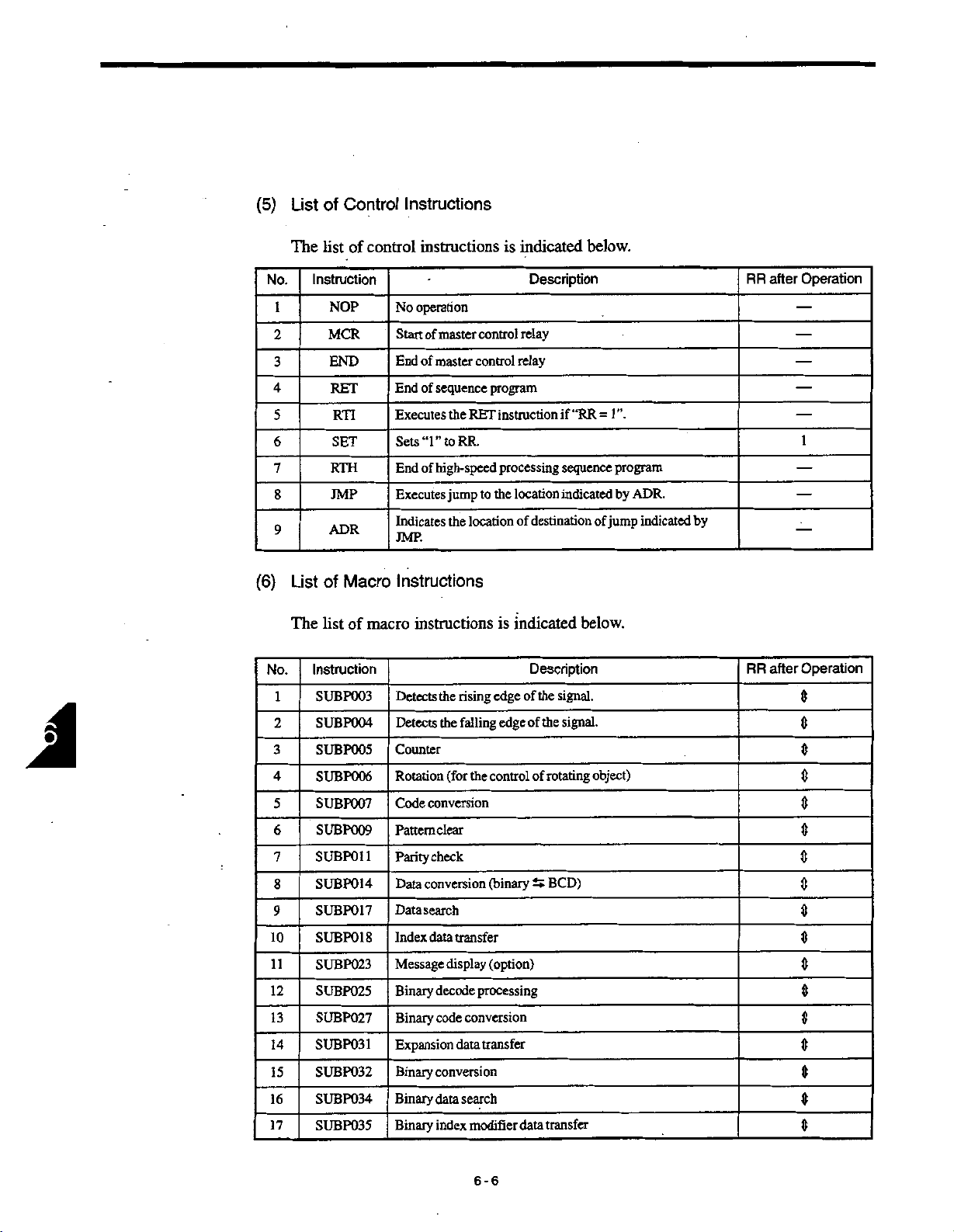
(5)
List
Control
of
Instructions
J
(6)
No.
1
2
3
4
5
6
7
8
9
No.
1
2
3
4
5
6
7
8
9
10
11
12
13
14
15
16
17
The
list
Instruction
NOP
MCR
END
RET
RTH
JMP
ADR
of
List
The
list
Instruction
SUBP003
SUBP004
SUBP005
SUBP006
SUBP007
SUBP009
SUB
SUB
SUBP017
SUBP018
SUBP023
SUBP025
SUBP027
SUBP031
SUBP032
SUBP034
SUBP035
of
RTI
SET
Macro
of
P011
POM
control
instructions
operation
No
Start
End
of
of
End
Executes
Sets
“1”
End
of
Executes
Indicates
JMP.
Instructions
macro
instructions
Detects
Detects
Counter
Rotation
Code
Pattemclear
Parity
Data
Data
Index
Message
Binary
Binary
Expansion
Binary
Binary
Binary
of
conversion
check
conversion
search
data
control
master
control
master
sequence
the
RET
RR.
to
high-speed
jump
the
location
the
rising
falling
the
(for
the
transfer
display
processing
decode
conversion
code
data
conversion
search
data
modifier
index
indicated
is
relay
relay
program
instruction
processing
the
location
to
of
indicated
is
edge
edge
control
(binary
(option)
transfer
data
Description
if
“RR
sequence
indicated
destination
below.
Description
signal.
of
the
the
of
signal.
rotating
of
BCD)
t*
transfer
below.
1
”.
=
program
by
of
jump
object)
ADR.
indicated
by
RR
RR
after
after
Operation
1
Operation
0
0
0
0
0
0
0
0
0
0
0
0
0
0
0
0
0
6-6
Page 45
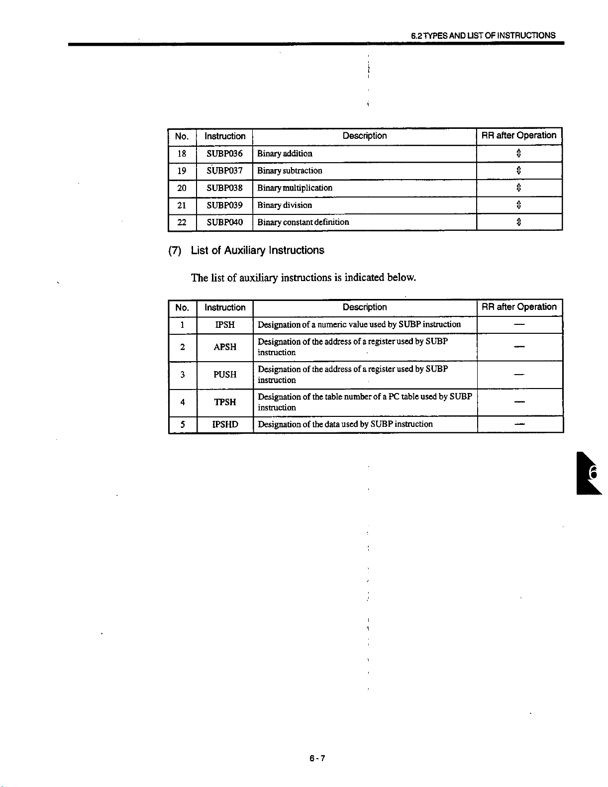
No.
18
19
20
21
22
Instruction
SUBP036
SUBP037
SUBP038
SUBP039
SUBP040
Binary
Binary
Binary
Binary
Binary
addition
subtraction
multiplication
division
constant
definition
i
Description
6.2
TYPES
AND
USTOF
RR
INSTRUCTIONS
after
Operation
0
0
0
0
0
(7)
No.
1
2
3
4
5
of
List
The
list
Instruction
PUSH
IPS
Auxiliary
of
IPSH
APSH
TPSH
HD
Instructions
auxiliary
Designation
Designation
instruction
Designation
instruction
Designation
instruction
Designation
instructions
numeric
of
a
the
address
of
address
the
of
the
table
of
the
of
data
indicated
is
Description
value
of
a
a
of
number
by
used
below.
used
by
register
register
ofaPC
SUBP
SUBP
instruction
by
used
SUBP
by
SUBP
used
table
used
instruction
by
SUBP
RR
after
Operation
k
6-7
Page 46
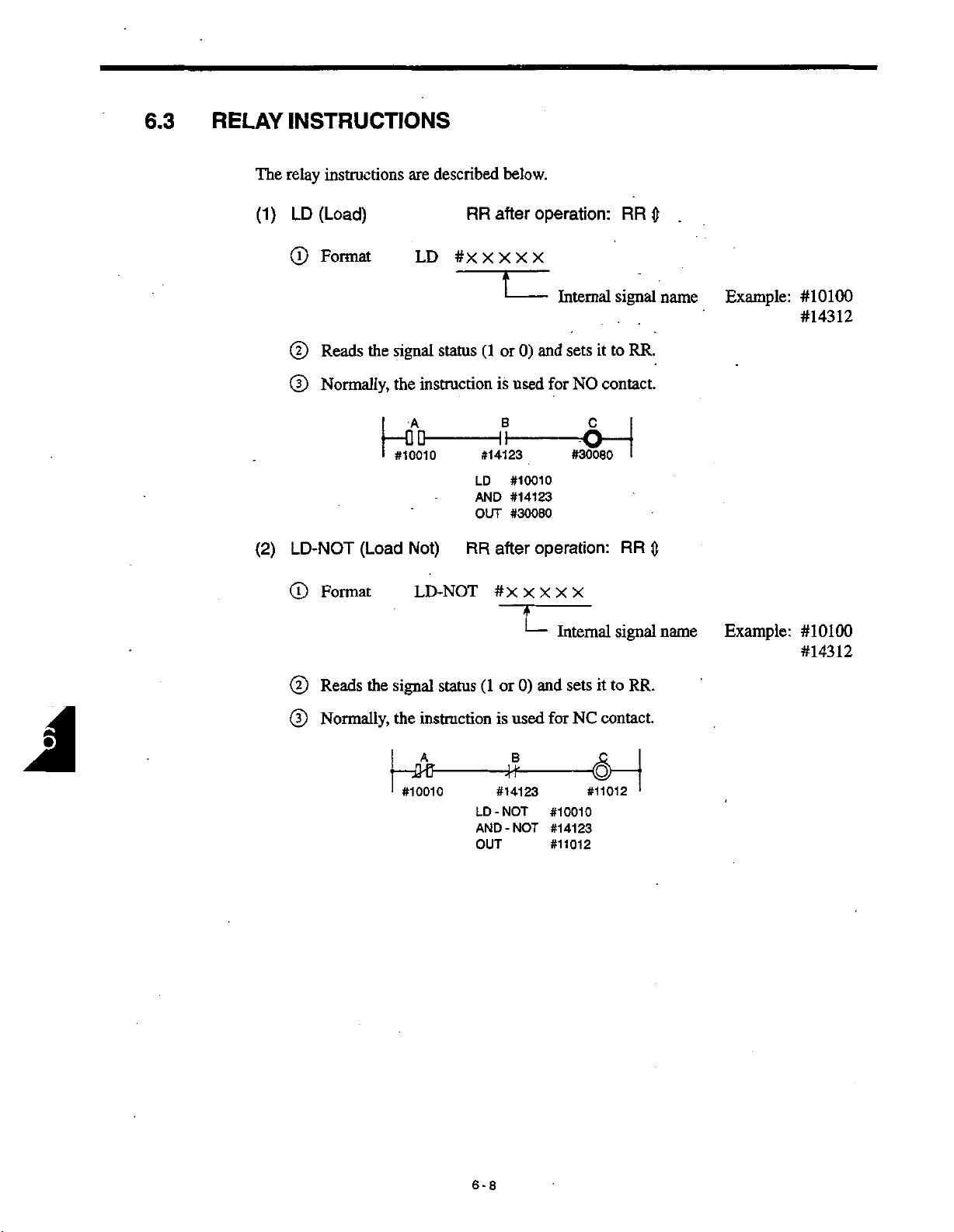
6.3
RELAY
INSTRUCTIONS
The
(1)
(2)
relay
instructions
(Load)
LD
(D
Format
(D
Reads
(D
Normally,
LD-NOT
(T)
Format
the
1
—
i
(Load
described
are
LD
#XXXXX
signal
instruction
the
status
DAQ-
#10010
Not)
LD-NOT
RR
(1or0)
#14123
LD
AND
OUT
RR
below.
after
is
used
B
#10010
#14123
#30080
after
#X
operation:
Internal
and
sets
for
NO
oH
#30080
operation:
X
X
X
X
RR
signal
to
it
RR.
contact.
I
RR
$
name
0
Example:
#10100
#14312
A
(D
(D
Reads
Normally,
the
signal
status
instruction
the
UHJ-
#10010
'
(1or0)
is
used
B
#14123
LD-NOT
-NOT
AND
OUT
IT
Internal
and
sets
for
#10010
#14123
#11012
NC
signal
to
it
contact.
#11012
RR.
1
name
Example:
#10100
#14312
6-8
Page 47
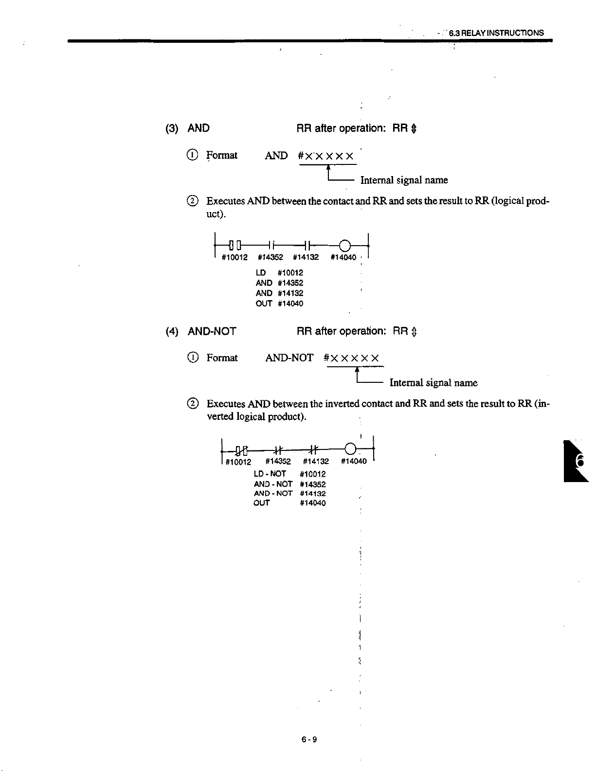
-
RELAY
6.3
INSTRUCTIONS
(3)
©
(4)
AND
Format
Executes
©
uct).
1
#10012
AND-NOT
Format
©
Executes
©
verted
AND
#14352
LD
AND
AND
OUT
AND
logical
RR
AND
AND-NOT
product).
#XXXXX
between
#14132
#10012
#14352
#14132
#14040
RR
between
after
-
the
contact
after
#XXXXX
inverted
the
operation:
Internal
andRRand
0~
#14040
operation:
-
contact
RR
0
signal
sets
RR
0
Internal
RR
and
name
result
the
signal
and
name
sets
to
the
RR
result
(logical
to
prod¬
RR
(in¬
—m
—
#10012
=#
—
#14352
LD-NOT
AND-NOT
AND-NOT
OUT
+F
#14132
#10012
#14352
#14132
#14040
O"
#14040
1
5
|
—
1
it
6-9
Page 48

(5)
OR
(D
Format
OR
RR
#X
after
XXX X
operation:
RR
0
(6)
(2)
Executes
OR-NOT
(D
Format
(2)
Executes
verted
OR
-t-DO
#10012
#14352
#14132
OR
logical
between
#10012
LD
#14352
OR
#14132
OR
OUT
#14040
RR
OR-NOT
between
sum).
I
the
contact
after
#XXXXX
the
inverted
Internal
and
RR
rtSio
operation:
I
contact
signal
and
sets
RR
Internal
RR
and
name
the
0
signal
and
result
name
sets
to
the
RR
result
(logical
RR
to
sum).
(in¬
1
-r&fr
#10012
ft
#14352
ft
#14132
LD-NOT
OR-NOT
OR-NOT
OUT
6-10
—O
#14040
#10012
#14352
#14132
#14040
Page 49
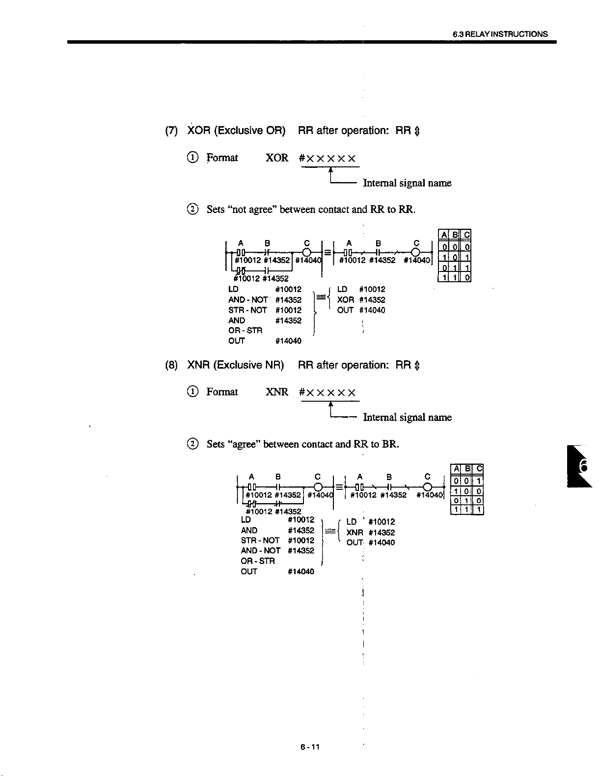
6.3
INSTRUCTIONS
RELAY
(7)
(8)
XOR
CD
©
XNR
©
(Exclusive
Format
“not
Sets
A
r—
OD
-
—
#10012
4W
#10012
LD
AND
STR-NOT
AND
OR
-
OUT
(Exclusive
Format
OR)
XOR
agree”
B
H
-
#14352
II
#14352
-NOT
STR
NR)
XNR
RR
#X
between
C
O
—
#140401
#10012
#14352
#10012
#14352
#14040
RR
#XXXXX
after
X
contact
—
—
“l
>
after
operation:
X
X
X
;
L
and
A
QD—
—
#10012
LD
XOR
OUT
operation:
ii
Internal
RR
B
II
-
—
*
#14352
#10012
#14352
#14040
i
Internal
RR
to
»*
RR
0
signal
RR.
C
O
—
#14040
$
signal
name
—
name
A
B
0
0
1o1
0
1
1
1
C
01
1
®
Sets
“agree”
A
-rOO
#10012
#10012*14352
LD
AND
STR-NOT
AND
OR
OUT
between
B
II
#14352
-NOT
STR
-
contact
#14040
#10012
#14352
#10012
#14352
#14040
C
O
—
=
and
=
RRtoBR.
A
00
—
—
#10012*14352
'
LD
(ÿ
XNR
1
OUT
II
!
I
I
’I
l
:
B
II
—
—
#10012
#14352
#14040
v
C
••
"O
#14040
—
A
B
0
0
1
0
0 0
1
111
1
0
I
6-11
Page 50

(9)
STR
(T)
(Store)
Format
STR
after
RR
#XXXXX
operation:
Internal
RR
signal
0
name
(10)
(2)
Sets
(D
Normally,
STR-NOT
(T)
Format
the
RR
(Store
contents
STO
Up
to
instruction
the
A
TOD
#10012
II
#14001
LD
OR
STR
OR
AND
OUT
NOT)
STR-NOT
6
1
of
RR
ST1
stacks
STR
-
to
stack
ST2
can
be
is
C
00
#10013
#14002
#10012
#14001
#10013
#14002
#14041
#XXXXX
used.
used
RR
and
for
o
#14041
after
executes
ST15
NO
contact.
E
operation:
theLDinstruction.
RR
$
©
Sets
the
contents
—fQfi
#10012
4
#14001
’
RR
of
A
LD-NOT
-NOT
OR
STR-NOT
-NOT
OR
AND
-STR
OUT
6-12
stack
to
M
#10013
#14002
#10012
#14001
#10013
#14002
#14041
-
and
c
D
Internal
executes
E
o
#14041
LD-NOT
the
signal
name
instruction.
Page 51

6.3
I
INSTRUCTIONS
RELAY
(11)
(12)
AND-STR
Format
©
(D
Executes
the
to
OR-STR
(AND
left
(OR
Store)
AND-STR
AND
by
one.
RR
AND
A
-pOO
#10012
B
O
#14001
LD
OR
STR-NOT
OR
AND
OUT
Store)
between
STO
ST1
—
-NOT
-STR
RR
and
RR
ST2
C
#10013
D
#14002
#10012
#14001
#10013
#14002
#14041
RR
after
stack
#14041
after
operation:
(STO)
and
ST15
E
o
i
operation:
sets
“0”
RR
the
RR
0
result
0
to
RR.
Stacks
shift
Format
©
ExecutesORbetween
©
to
the
left
by
OR-STR
one.
A
Q
-
pfl
—
#10012
C
H3
D
#10013
LD
AND
STR
AND
OR-STR
OUT
RR
stack
and
B
#14001
D
#14002
#10012
#14001
#10013
#14002
#14041
(STO)
E
o
#14041
'I
1
J
and
sets
the
result
to
RR.
Stacks
shift
l
6-13
Page 52

(13)
OUT
RR
after
operation:
RR
—
®
©
Format
Writes
the
result
f-0&
I
OUT
#10012
#XXXXX
of
operation
LD
AND
OUT
(RR)
B
#14001
#10012
#14001
#14041
Internal
the
to
signal
relay.
C
o
—
#14041
name
6-14
Page 53
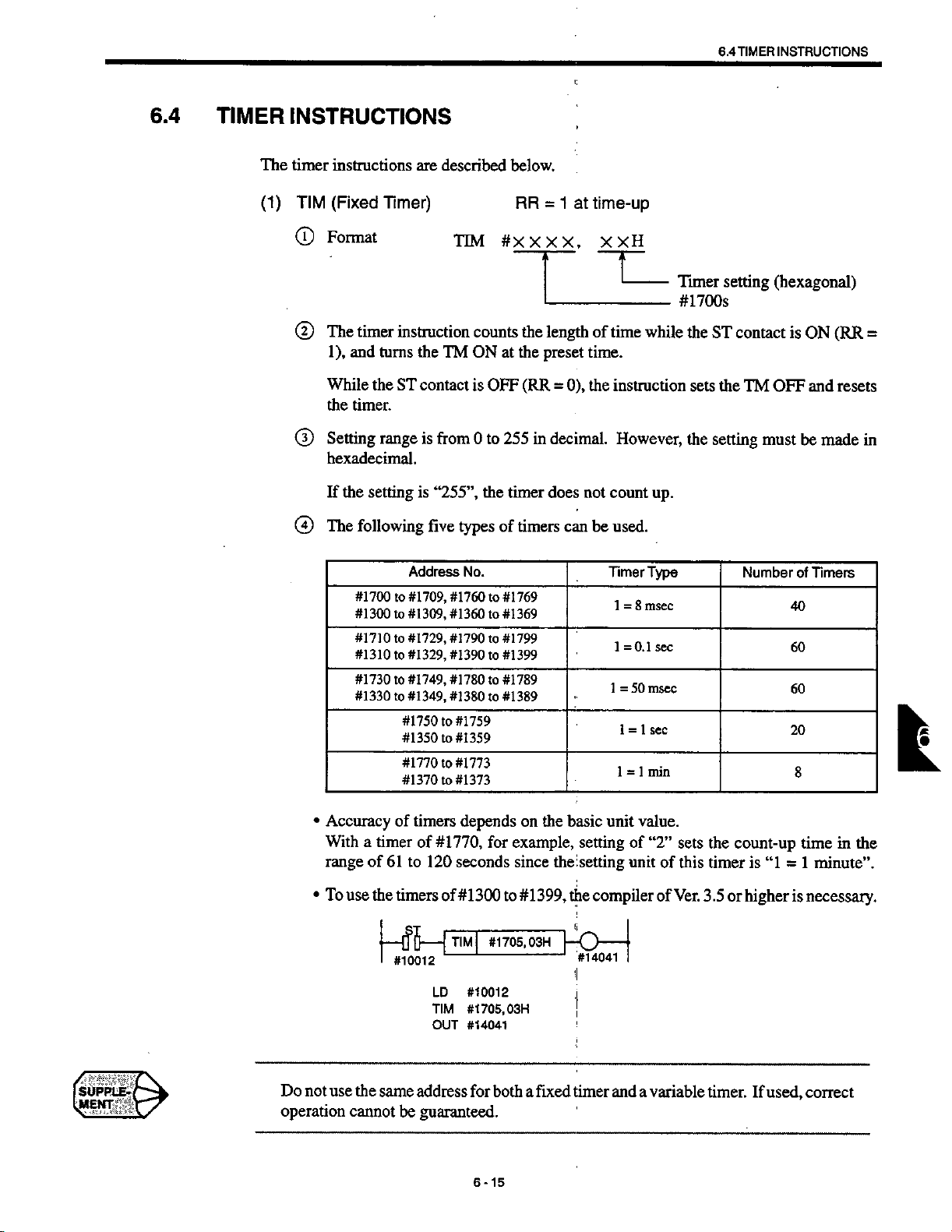
6.4
TIMER
INSTRUCTIONS
6.4
TIMER
The
(1)
INSTRUCTIONS
timer
instructions
(Fixed
TIM
Format
©
The
©
1),
and
While
the
timer.
Setting
©
hexadecimal.
the
If
@
The
timer
setting
following
Timer)
instruction
turns
the
ST
range
are
described
the
TM
contact
is
from
is
“255”,
five
TTM
counts
ON
is
0to255
types
OFF
the
of
below.
RR
#xm,
the
the
at
(RR
timer
timers
1
=
-
length
preset
=
decimal.
in
does
can
at
0),
not
time-up
XXH
-
time
of
time.
the
instruction
However,
count
be
used.
while
up.
Timer
#1700s
the
ST
the
sets
the
setting
setting
contact
TM
must
(hexagonal)
(RR
is
ON
and
OFF
be
resets
made
=
in
#1700
#1300
#1710
#1310
#1730
#1330
Accuracy
•
With
range
To
use
•
Address
#1709,
to
#1309,
to
#1729,
to
#1329,
to
#1749,
to
#1349,
to
#1750to#1759
#1350
to
#1770
to
#1370
to
timers
of
a
timer
of
61to120
the
--
of
timers
[fl5
-
#10012
#1770,
of
1
LD
TIM
OUT
No.
#1760to#1769
#1360
#1790to#1799
#1390
#1780to#1789
#1380
#1359
#1773
#1373
seconds
TIM
#1369
to
#1399
to
#1389
to
depends
for
#1300
to
#1705,
|
#10012
#1705,
03H
#14041
on
example,
since
#1399,
03H
Timer
basic
the
the
unit
setting
setting
compiler
the
vb-4
#14041
1
1
1
1
8
=
=0.1
50
=
1=1
=
of
unit
I
Type
msec
sec
msec
sec
1
min
value.
“2”
of
of
sets
this
Ver.
NumberofTimers
the
count-up
timer
is
“1
higher
3.5
or
40
60
60
20
8
time
1
minute”.
=
is
necessary.
in
the
Do
not
use
operation
the
same
cannot
address
be
guaranteed.
for
6-15
both
fixed
a
timer
and
variable
a
timer.
If
used,
correct
Page 54

(2)
TMR
®
(Variable
Format
Timer)
TMR
RR
#xm,
1
time-up
at
=
#xxxx
(D
The
1),
and
While
the
timer.
Setting
®
hexadecimal.
If
the
Write
®
procedure.
(s)
Five
timer
turns
the
range
setting
the
types
}
—
I
instruction
the
ST
contact
is
from
is
“255”,
value
timer
this
In
timers
of
00
«
—
#10012
LD
TMR
OUT
TM
case,
#10012
#1705,
#14041
counts
ON
OFF
is
0
to
the
from
the
can
#1705,
at
255
timer
the
be
used
#7042
length
the
the
preset
(RR
decimal.
in
does
NC
timer
as
#7042
KH
of
time.
0),
the
=
not
keyboard
can
value
with
u
time
while
instruction
However,
count
up.
following
by
written
be
TIM
the
Sequencer
address:
#1700s
ST
the
the
sets
contact
the
setting
the
decimal
a
in
instruction.
parameter
pra7000s
is
OFF
TM
be
must
parameter
value.
ON
and
made
(RR
=
resets
in
writing
6-16
Page 55

REGISTER
6.5
INSTRUCTIONS
6.5
REGISTER
register
The
(1)
INR
(J)
(D
(D
®
©
©
INSTRUCTIONS
described
instructions
(Increment
Format
instruction
The
=1).
(RR
An
ST
contact
The
instruction
while
the
There
is
no
The
following
are
Register)
INR
adds
the
If
must
adds
ST
contact
function
examples
ST
-
DO
#10012
LD
INR
ST
-
#XXXX
“+1”
contact
be
“+1”
is
to
detect
INR
-
#10012
#1505
below.
RR
the
to
is
entered
the
to
ON.
overflow.
show
#1505
-
after
content
OFF
before
content
when
operation:
of
the
(RR
the
of
If
the
0),
=
INR
the
timer
a
register
RR
register
addition
instruction.
counts
of
#1500s
in
register
—
when
is
not
intervals
to
FFH,
is
the
ST
contact
executed.
“4
of
returns
it
used.
is
ON
n”
msec
x
OH.
to
(2)
DCR
©
©
®
®
©
Format
The
(RR
An
The
while
There
(Decrement
instruction
=1).
ST
instruction
the
If
contact
ST
the
contact
-
#10012
no
is
function
INR
Register)
DCR
adds
ST
must
adds
ST
-
00
-
LD
DCR
to
#1505
RR
#XXXXX
to
“-1”
contact
entered
be
to
“-1
”
ON.
is
DCR
-
#10012
#1505
detect
operation:
after
'i
content
OFF
before
content
Register
J
(RR
i
-
the
is
the
J
•l
#1505
;
underflow.
of
the
of
=
the
If
the
0),
DCR
register
timer
a
register
addition
The
register
described
are
RR
—
when
is
not
instruction.
intervals
in
counts
to
instructions
below.
ST
the
contact
executed.
of
OH,
returns
it
“4
t
is
ON
msec
n”
x
to
FFH.
6-17
Page 56
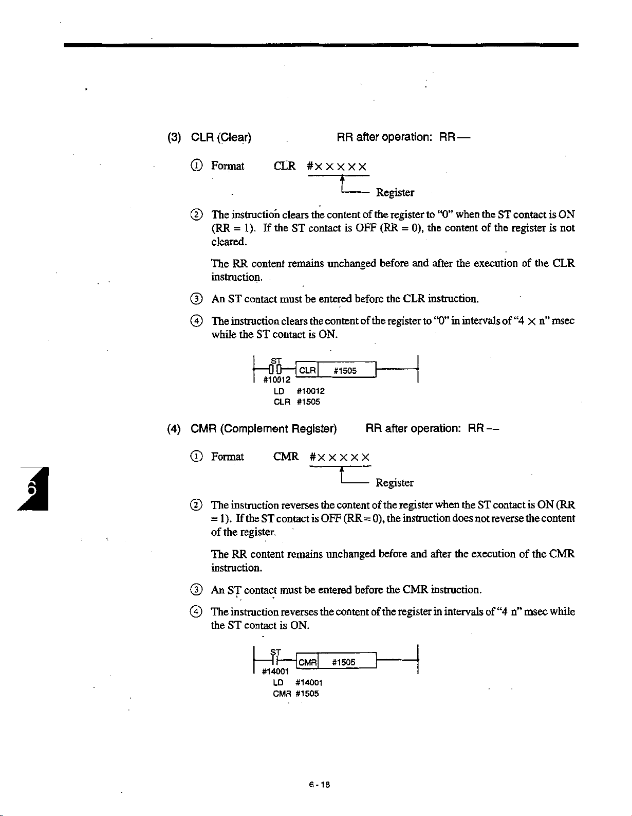
(3)
CLR
(Clear)
RR
after
operation:
RR
—
(4)
Format
©
The
©
(RR
cleared.
The
instruction.
An
©
@
The
while
CMR
Format
©
CLR
instruction
1).
=
RR
ST
contact
instruction
the
(Complement
the
If
content
ST
contact
j
00
—
I
#10012
LD
CLR
CMR
must
#XXXXX
clears
ST
contact
remains
be
clears
the
is
[CLR[
—
-
#10012
#1505
Register)
#XXXXX
T
the
content
is
unchanged
entered
content
ON.
#1505
Register
of
the
OFF
before
the
of
RR
register
(RR
=
before
CLR
the
register
after
to
“0”
0),
the
content
and
after
instruction.
“0”
in
to
operation:
the
when
of
the
execution
intervals
RR
—
ST
the
of
contact
register
of
the
“4
n”
X
is
ON
is
not
CLR
msec
J
The
©
=
of
The
instruction.
An
©
The
©
the
instruction
).
If
the
1
the
register.
content
RR
ST
contact
instruction
ST
contact
1
I
reverses
ST
contact
remains
must
reverses
is
ON.
—?l—
#14001
LD
CMR
the
OFF
is
entered
be
the
[cmr[
-
#14001
#1505
I
content
(RR
unchanged
content
#1505
Register
of
0),
=
before
of
the
register
the
before
the
register
the
when
instruction
after
and
CMR
instruction.
in
intervals
the
does
execution
the
ST
not
of
contact
reverse
“4
n”
is
the
the
of
msec
(RR
ON
content
CMR
while
6-18
Page 57
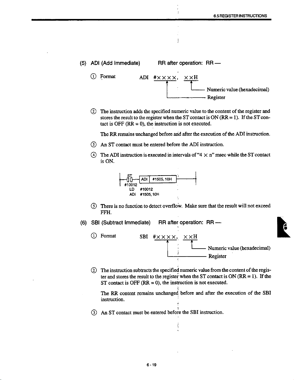
REGISTER
6.5
INSTRUCTIONS
(5)
(Add
ADI
Format
©
(D
The
instruction
stores
is
tact
TheRRremains
(D
An
ST
The
is
ADI
ON.
0
Immediate)
ADI
#X
adds
the
specified
the
the
result
(RR
OFF
contact
instructionisexecuted
00
-
#10012
LD
ADI
register
to
0),
the
=
unchanged
entered
be
must
ADI
-
1
I
#10012
#1505,
#1505,
10H
after
RR
X,
X X
numeric
when
instruction
before
and
before
intervals
in
1
0H
operation:
XXH
L_
value
the
ST
contact
is
executed.
not
after
the
ADI
of
|
RR
—
Numeric
Register
the
to
content
is
ON
the
executionofthe
instruction.
“4
msec
n”
x
(RR
(hexadecimal)
value
of
the
=1).
If
ADI
the
while
register
the
instruction.
ST
and
ST
con¬
contact
(6)
There
®
FFH.
(Subtract
SBI
Format
0
The
©
ter
ST
The
instruction.
An
©
function
is
no
Immediate)
instruction
and
stores
RR
is
content
contact
contact
ST
SBI
subtracts
result
the
(RR
OFF
remains
must
detect
to
to
=
entered
be
#XXXX,
the
the
0),
overflow.
after
RR
i
specified
register
the
instruction
unchanged
f
before
Make
sure
operation:
XXH
I
numeric
when
before
the
value
the
ST
is
not
and
SBI
instruction.
the
that
RR
—
Numeric
Register
the
from
contact
executed.
the
after
will
result
(hexadecimal)
value
content
(RR
is
ON
execution
not
of
=1).
of
exceed
regis¬
the
If
the
l
the
SBI
6-19
Page 58

0
The
is
ON.
instruction
SBI
K
I
#10012
‘
D
LD
SBI
-
is
executedinintervals
SBI
#1505,20H
_
#10012
#1505,20H
of
“4
while
the
ST
contact
msec
n”
x
(7)
There
0
of
ANI
Format
®
The
®
tent
(RR
The
instruction.
An
®
The
0
is
is
register”.
(AND
instruction
of
=
RR
ST
ANI
ON.
no
function
Immediate)
executes
the
register
1).
the
If
ST
content
contact
remains
must
instruction
SB
—
—
J
I
#10012
detect
to
ANI
and
stores
contact
be
is
executed
'
ANI
LD
ANI
underflow.
RR
X
#X
-
between
AND
the
is
OFF
unchanged
entered
#10012
#1505,
before
#1505,551-1
55H
after
X,
X
result
(RR
intervals
in
\
Make
operation:
XH
X
-
the
specified
register
to
the
0),
the
=
the
and
ANI
of
“4
before
that
sure
RR
“numeric
—
Numeric
Register
numeric
when
instruction
the
after
instruction.
n”
msec
X
value
(hexadecimal)
value
value
the
ST
contact
is
not
execution
while
the
contents
and
the
con¬
is
executed.
of
the
ANI
contact
ST
ON
Register
Numeric
Result
Value
D7
0
0
0
6-20
D6
0
1
0
D5
1
0
0
,
D4
1
1
1
D3
0
0
0
D2
0
1
0
D1
1
0
0
DO
1
1
1
Page 59

REGISTER
6.5
INSTRUCTIONS
(8)
(OR
ORl
(D
Format
The
©
of
=
The
instruction.
(D
An
The
©
is
Immediate)
instruction
register
the
1).
If
the
content
RR
ST
contact
instmctionisexecuted
ORI
ON.
executes
and
ST
must
I
I
#10012
ORI
stores
contact
remains
be
ST
-
00
RR
#X
between
OR
result
the
is
OFF
unchanged
entered
ORI
-
#10012
LD
#1505,
ORI
after
X X
(RR
before
in
#1505,
55H
operation:
.
X,
XXH
the
specified
register
the
to
0),
the
=
before
the
intervals
55H
.
when
instruction
after
and
instruction.
ORI
“4
of
x
RR
—
Numeric
Register
numeric
the
is
the
msec
n”
(hexadecimal)
value
value
and
ST
contact
executed.
not
execution
while
the
the
is
of
ST
content
(RR
ON
the
ORI
contact
Register
Numeric
Result
Value
D7
0
0
0
D6
0
D5
1
1
0
D4
1
1
D3
0
0
D2
D1
o
1
1
0
DO
I
1
L
1
1
1
1
0
1
1
,
1
6-21
:
Page 60
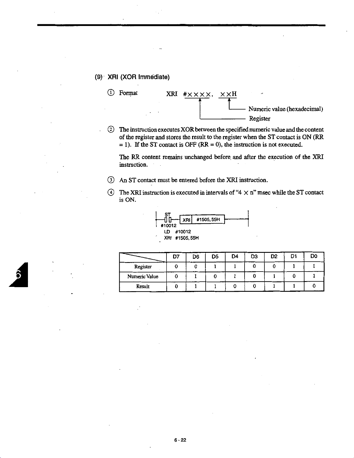
(9)
XRI
©
(XOR
Format
Immediate)
XRI
#XXXX,
-
X
XH
(hexadecimal)
-
Numeric
value
Register
J
The
©
of
=
The
instruction.
An
®
The
®
is
instruction
the
register
the
1).
If
RR
content
ST
contact
instructionisexecuted
XRI
ON.
Register
Numeric
Result
and
ST
-
Value
executes
stores
contact
remains
must
be
ST
-
00
#10012
LD
XRI
D7
XOR
result
the
OFF
is
unchanged
entered
XRI
#10012
#1505,55H
D6
0
0
0
between
to
(RR
=
before
in
intervals
#1505,
5SH
D5
0
1
1
the
specified
the
register
0),
the
before
the
1
0
1
instruction
and
instruction.
XRI
of
“4
D4
1
1
0
numeric
when
after
n”
X
D3
0
0
0
the
ST
is
not
the
execution
msec
value
and
contact
executed.
while
the
D2
0
1
1
D1
0
1
1
the
is
of
ST
content
ON
the
contact
DO
(RR
XRI
1
1
0
6-22
Page 61
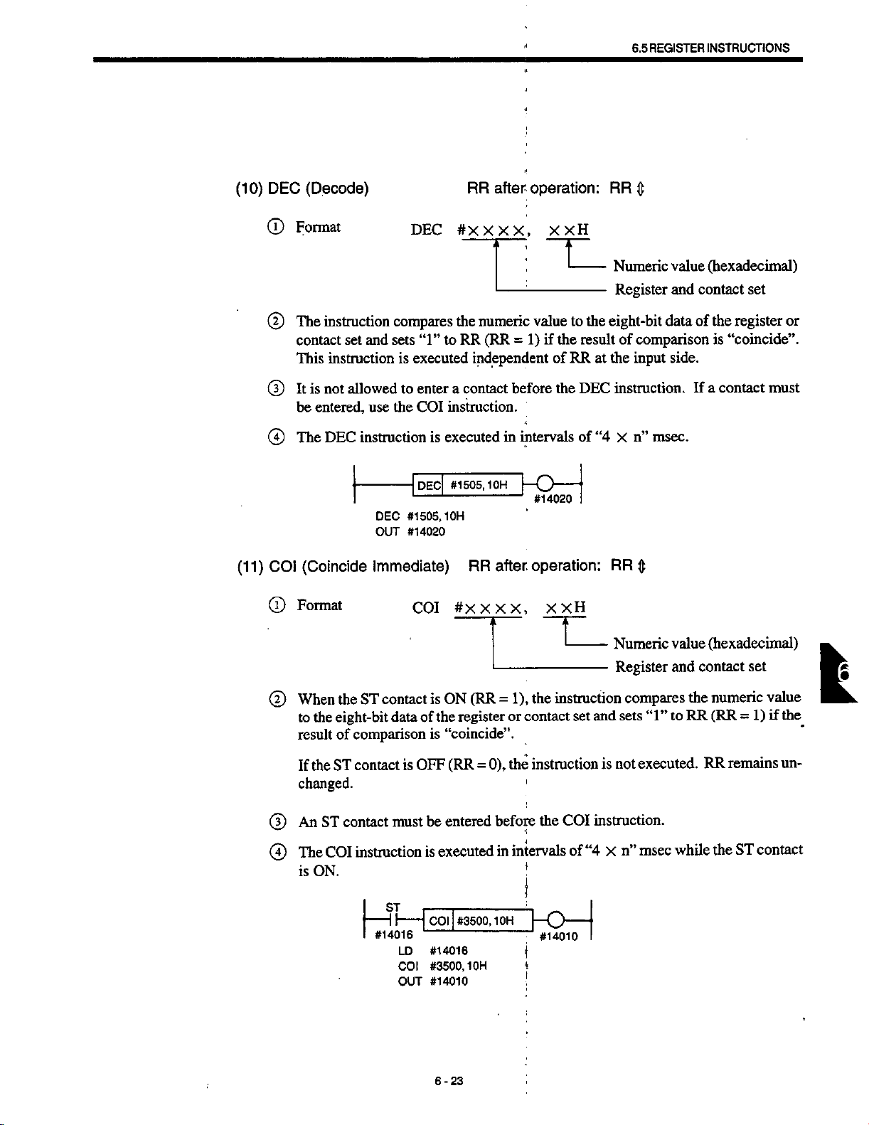
(10)
DEC
®
(Decode)
Format
DEC
RR
#xm,
after
operation:
XXH
RR
6.5
REGISTER
0
INSTRUCTIONS
(11)
(D
(D
®
COI
(T)
instruction
The
contact
This
instruction
not
It
is
entered,
be
DEC
The
(Coincide
Format
and
set
allowed
use
instruction
DEC
OUT
Immediate)
compares
sets
is
to
the
to
“1”
executed
enter
instruction.
COI
executed
is
-|
DEcf
1
1
-
-
#1505,1
#14020
CO!
the
numeric
(RR
RR
independent
a
contact
in
#1505,1
OH
OH
after
RR
XX,
#XX
-
valuetothe
1)
if
=
before
intervals
j—
O
#14020
operation:
XXH
I
the
of
the
--
RR
-
result
at
DEC
of
“4
Numeric
Register
eight-bit
of
comparison
the
input
instruction.
msec.
n”
X
RR
0
Numeric
Register
(hexadecimal)
value
contact
and
dataofthe
is
side.
a
contact
If
(hexadecimal)
value
and
contact
set
register
“coincide”.
or
must
set
(2)
(D
(4)
When
the
the
to
eight-bit
of
result
the
ST
If
changed.
ST
An
The
is
contact
COI
ON.
contact
ST
data
of
comparison
must
ST
l
-
#14016
LD
COI
OUT
is
OFF
contact
instruction
ON
is
register
the
“coincide”.
is
(RR
entered
be
executed
is
#3500,1
COI
#14016
#3500,1
#14010
6-23
(RR
=
OH
1),
=
or
0),
the
before
intervals
in
OH
instruction
the
contact
t
set
instruction
COI
the
of
“4
KH
compares
sets
not
n”
X
“1”
executed.
msec
and
is
instruction.
the
RR
to
while
numeric
(RR
=
remains
RR
ST
the
value
1)
if
un¬
contact
I
the
Page 62

(12)
CMP
(Compare)
RR
after
operation:
RR
0
0
0
0
0
Format
The
instruction
contact
Register
Register
instruction
This
is
not
It
entered,
be
The
CMP
set
and
(contact)
(contact)
allowed
use
instruction
-|CMP|
CMP
OUT
CMP
compares
“1"
sets
is
to
the
#3510,1
#14500
or
§
Numeric
Numeric
<
executed
enter
instruction.
CPI
executed
is
#3510,
OH
#XXXX,
numeric
the
depending
“0”
value:
value:
independent
a
contact
in
10H
TL
value
RR
before
intervals
XXH
on
RR
=
of
RR
the
#4951
-+Z1
#49510
-Z1
to
the
=
0
CMP
of
Numeric
Register
the
eight-bit
result
1
the
at
instruction.
“4
x
10H
0
=
=ON
<10H
OFF
=
value
and
data
of
comparison.
side.
input
msec.
n”
(hexadecimal)
the
a
contact
set
register
contact
of
If
or
must
J
6-24
Page 63

REGISTER
6.5
1
INSTRUCTIONS
(13)
CPI
(D
©
(D
®
Fprrnat
If
(Compare
When
the
eight-bit
the
to
“Register
ST
the
changed.
An
The
is
contact
contact
ST
instructionisexecuted
CPI
ON.
Immediate)
CPI
ST
contact
dataofthe
(contact)
is
must
II
|
—
—
I
#14002
LD
CPI
OUT
is
Numeric
=
OFF
be
CPI
|
-
#14002
#3510,1
#14500
RR
#XXXX,
(RR
ON
register
(RR
=
entered
#3510,1
|
OH
after
1),
=
value”.
0),
the
before
intervals
in
OH
operation:
•
XXH
T
instruction
the
or
contact
instruction
CPI
the
K>—
#14500
Numeric
Register
and
set
is
instruction.
“4
of
x
I
I
RR
0
compares
sets
not
executed.
msec
n”
value
and
“1”
while
contact
the
to
(hexadecimal)
set
numeric
RR
RR
the
value
(RR
=
remains
ST
contact
1)
un¬
if
(14)
MVI
(T)
©
®
®
(Move
Format
function
The
(RR
=
ST
An
MVI
The
is
ON.
Immediate)
transfers
1).
the
If
contact
must
instruction
ST
|
-
#14002
MVI
ST
LD
MVI
the
contact
entered
be
executed
is
|
MVI
1
#14002
#1505,
after
RR
#XXXXi
numeric
is
OFF
before
in
#1505,
15H
15H
operation:
i
X
;
value
to
(RR
=
the
II
intervals
j
'!
J
XH
T
the
0),
MVI
of
register
the
“4
RR
—
Numeric
Register
when
instruction
instruction.
n”
msec
x
(hexadecimal)
value
the
ST
is
not
while
the
ST
is
contact
contact
executed.
L
ON
6-25
Page 64

(15)
ADD
(Add
Register)
RR
after
operation:
RR
.
—
©
©
.
©
@
Format
function
The
register
tent
in
R2.
ter
The
content
unchanged.
the
ST
ST
ADD
contact
contact
instruction
If
An
The
is
ON.
ADD
executes
1
R
when
in
register
is
must
ST
#14012
LD
ADD
addition
the
Rl
OFF
be
entered
is
executed
ADP|
#14012
#1501,
#XXXX,
between
contact
SR
remains
(RR
0),
=
before
in
#1501,#1502
#1502
#XXXX
U
the
content
(RR
ON
is
unchanged
instruction
the
ADD
the
intervals
of
r
Register
Operating
the
in
)
1
and
=
the
and
is
status
not
instruction.
“4
msec
n”
X
be
to
register
the
of
RR
while
R2
register
stores
executed.
operated
(Rl)
the
and
result
to
remains
also
the
ST
contact
(R2)
con¬
regis¬
B
(16)
(17)
©
SUB
©
©
ANR
©
There
is
(FFH).
255
(Sub
Register)
SUB
The
tion
that
(R2
-
There
is
satisfied:
(AND
The
ANR
tion
that
(R2
AND
function
no
instruction
the
SUB
R2)
Rl
>
—
no
function
Rl
R2
Register)
instruction
the
ANR
Rl
detect
to
RR
basically
is
instruction
detect
to
RR
basically
is
instruction
R2)
overflow.
operation:
after
the
same
operation:
the
same
subtraction.
AND
executes
underflow.
after
executes
Make
as
Make
as
the
that
sure
RR
instruction
ADD
that
sure
RR
ADD
instruction
the
operation.
the
—
the
—
result
following
will
with
with
not
the
is
the
exceed
excep¬
always
excep¬
6-26
Page 65
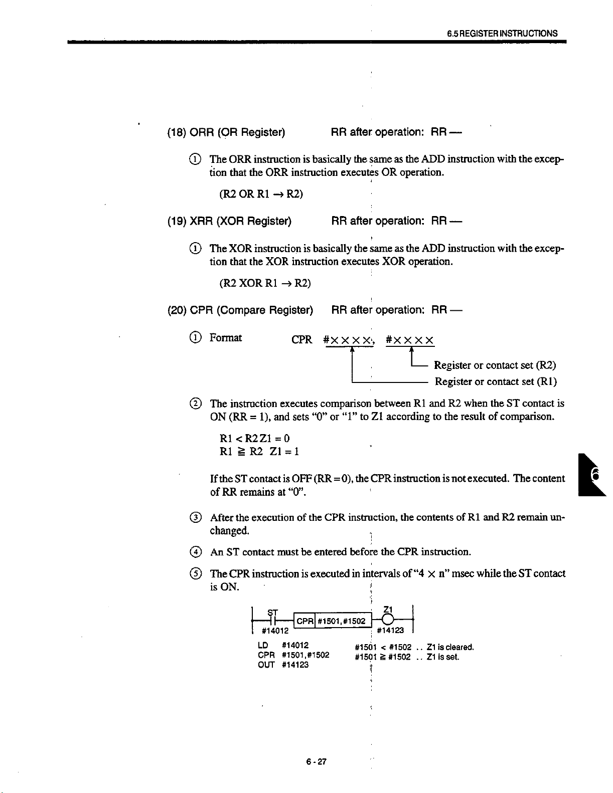
REGISTER
6.5
INSTRUCTIONS
(18)
(19)
(20)
ORR
(T)
XRR
(D
CPR
(T)
©
Register)
(OR
The
ORR
tion
that
(R2
OR
(XOR
The
XOR
tion
that
(R2
XOR
(Compare
Format
instruction
The
(RR=1),
ON
instruction
the
ORR
-4
R1
Register)
instruction
the
XOR
-4
R1
Register)
executes
and
basically
is
instruction
R2)
basically
is
instruction
R2)
sets
“0”
#xxxx,
comparison
CPR
after
RR
executes
after
RR
executes
RR
“1”
or
operation:
the
same
as
OR
operation:
same
the
XOR
operation:
after
#xxxx
betweenRland
according
to
Z1
RR
the
ADD
operation.
RR
the
as
ADD
operation.
RR
L
Register
to
—
instruction
—
instruction
—
Register
when
R2
result
the
or
or
with
with
contact
contact
the
of
the
excep¬
excep¬
the
(R2)
set
(Rl)
set
ST
contact
comparison.
is
If
of
After
®
changed.
An
®
The
©
is
Rl
Rl
the
RR
ST
CPR
ON.
<R2Z1
§
R2
ST
contact
remains
the
execution
contact
instruction
—ff—
LD
CPR
OUT
=0
Z1=1
is
at
must
#14012
#14012
#1501,
#14123
OFF
“0”.
of
be
is
IcprI
-
0),
(RR
=
CPR
the
entered
executed
#1502
#1501.
#1502
CPR
the
instruction,
!
before
in
the
intervals
i
'j
H£-
#14123
|
#1501
<
£
#1501
#1502
#1502
instruction
the
contents
instruction.
CPR
“4
of
x
is
..
Z1
is
Z1
..
not
is
msec
n”
cleared.
set.
executed.
andR2remain
Rl
of
while
the
The
ST
content
L
un¬
contact
6-27
Page 66

(21)
COR
©
(Coincide
Format
Register)
COR
RR
#X
after
X
operation:
X,
X
#XXX
RR
X
$
J
(2)
(5)
®
(D
instruction
The
(RR
ON
Rl
=
Rl
*
the
ST
If
remains
RR
of
After
the
changed.
An
ST
contact
The
COR
is
ON.
executes
1),
=
R2
R2
contact
executionofthe
instruction
-
LD
COR
OUT
sets
and
Zl=l
=0
Z1
is
OFF
unchanged.
must
ST
|
II
—
-
-
#14012
#14012
#1501,
#14123
_
comparison
or
“0”
(RR
=
COR
entered
be
is
executed
_
|
#1501,
COB
#1502
between
Z1
to
“1”
0),
COR
the
instruction,
before
intervals
in
#1502
#1501
=
#1
501
*
according
instruction
the
the
COR
of
Z1
|
-
O
—
#14123
#1502
#1502...
L
Register
Register
andR2when
Rl
to
contents
instruction.
“4
n”
x
Z1
...
is
is
Z1
the
result
is
not
of
msec
set
cleared.
or
contact
contact
or
ST
the
of
comparison.
executed.
and
while
R2
the
Rl
set
set
contact
content
The
remain
ST
contact
(R2)
(Rl)
is
un¬
(22)
MOV
©
©
©
(Move
Format
The
function
contact
The
content
of
the
the
If
An
ST
Register)
transfers
(RR=1).
is
ON
the
of
instruction.
contact
ST
contact
must
MOV
register
OFF
is
be
6-28
RR
#XXXX,
the
content
Rl
(RR=0),
entered
operation:
after
the
of
remains
the
before
#XXXX
U
register
unchanged
instruction
MOV
instruction.
MOV
the
RR
—
Register
Register
to
Rl
before
(R2)
(Rl)
register
after
and
is
not
when
R2
the
execution
executed.
the
ST
Page 67

REGISTER
6.5
NSTRUCTIONS
I
(23)
©
DST
©
©
The
MOV
is
ON.
(Data
Format
instruction
The
meric
R2.
The
content
the
of
instruction
ST
-II-
#14012
LD
MOV
Store)
executes
value
when
of
the
instruction.
is
executed
Lovl
'—'
#14012
#1501
DST
the
ST
register
#1501,
,#1502
RR
#XXXX,
AND
contact
remains
Rl
in
intervals
#1502
f
'
operation:
after
between
is
ON
of
“4
x
RR
#XXXX,
the
content
1),
(RR
and
=
unchanged
msec
n”
—
XXH
of
the
stores
before
while
register
the
result
and
after
ST
the
Numeric
(hexadecimal)
Register
Register
Rl
and
to
execution
the
contact
value
(R2)
(Rl)
nu¬
the
register
©
©
If
B:
An
The
is
the
“0”
ON.
ST
contact
RegisterRl
Numeric
Register
or
“1"
contact
ST
instruction
DST
Value
R2
is
ST
-
I
#14012
must
OFF
DST
LD
DST
D7
B
0
0
entered
be
executed
is
(RR
#1501,
#14012
#1501,
=
#1502,
D6
B
0
0
0),
the
#1502,
OFH
D5
;
1
before
intervals
in
DST
B
0
0
the
instruction
OFH
D4
DST
of
-
D3
B B
0
0
instruction.
“4
n”
X
1
B
msec
is
not
executed.
D2
B
1
B
the
while
D1
B
1
B
ST
L
DO
B
1
B
contact
6-29
Page 68

(24)
DIN
0
(Data
Format
Insert)
DIN
RR
#XXXX,
after
operation:
#XXXX,
RR
—
XXH
J
@
0
0
instruction
The
the
and
ST
contact
data)
the
If
An
ST
The
DIN
is
ON.
executes
complement
is
ON
contact
ST
contact
must
instruction
ff—
I
—
I
#14012
Rl
R2
n
Result
(RR
is
OFF
be
is
LD
DIN
AND
numeric
the
of
=1)
and
(RR
entered
executed
[ssrr
#1
-
#14012
#1501,
D7
A
B
0
B
between
stores
0),
=
before
intervals
in
,
#1
501
#1502,
D6
A
B
0
B B
Rl
value,
the
the
DIN
the
502,
OFH
D5
A
B
0
and
then
result
instruction
DIN
of
--
[
OFH
D4
A
B B
B
the
numeric
between
OR
OR
of
instruction.
n”
“4
X
D3
A A
0
1
A
value,
to
R2.
is
not
msec
Numeric
(hexadecimal)
Register
Register
and
the
results
(Extraction
executed.
the
while
D2
B
I
A
D1
(R2)
between
when
of
ST
contact
A
B
1
A
value
(Rl)
R2
the
the
DO
A
B
1
A
“0”
“1”
or
6-30
A,
B:
Page 69
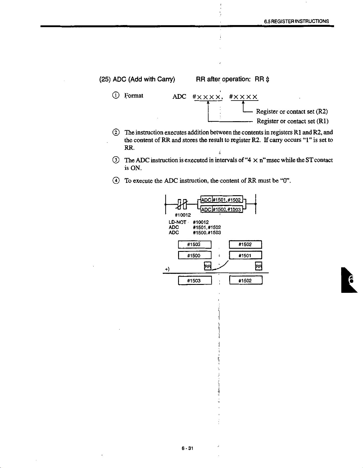
REGISTER
6.5
INSTRUCTIONS
(25)
ADC
©
©
©
©
(Add
Format
instruction
The
the
content
RR.
ADC
The
is
ON.
To
execute
with
Carry)
of
RR
instruction
the
ADC
executes
and
is
ADC
instruction,
1
#10012
LD-NOT
ADC
ADC
|
RR
#XXX
addition
the
stores
executed
lADCl#1
ADC
#10012
#1501,
#1500,
#1503
operation:
after
X,
between
result
i
intervals
in
the
content
501
l#1500,
r
#1502
#1503
#XXXX
the
register
to
,#1502
#1503
|
U
contents
R2.
“4
of
of
RR
}-|
H
#1502
RR
0
Register
Register
in
If
carry
msec
n”
X
must
or
contact
contact
or
registers
occurs
while
be
“0”.
Rl
the
set
set
and
“1”
ST
(R2)
(Rl)
and
R2,
is
set
contact
to
#1500
+)
[
#1503
J
''
|
*1501
I
0
|
#1502
~]
L
'i
j
6-31
Page 70

(26)
ADDW
Format
©
(ADD
Word
Register)
ADDW
after
RR
#XXXX,
operation:
#X
X
RR
X
—
X
©
©
@
instruction
The
(WR2)
stores
(WR1)
the
If
ST
An
The
ADDW
is
tact
double-length
and
result
the
(WR2)-»(WR2)
+
ST
contact
contact
ON.
must
instruction
|
HH
—
1
#14012
LD
ADDW
executes
addition
register
to
double-length
(RR
OFF
is
be
entered
executedinintervals
is
|ADDW|
—
-
#14012
#1500,
=
#1500,
#1502
between
(WR1)
register
0),
the
before
#1502
the
when
(WR2).
ADDW
the
ADDW
H
t
Low
register
Low
register
contents
the
ST
contact
instruction
instruction.
“4
of
n”
x
of
side
side
of
double-length
is
msec
double-length
(WR2)
double-length
of
(WR1)
is
ON
not
executed.
while
(RR
the
register
=1)
and
ST
con¬
©
There
is
FFFFH.
<Description>
+)
function
no
#1503|
of
[content
of
[content
|
to
*1500
#1503
detect
6-32
(WR2)
Content
(WR1J
1
Corilenl
#1502
(WR2)
overflow.
of
#1502
ol
H500
Make
I
1
sure
that
the
result
will
not
exceed
Page 71
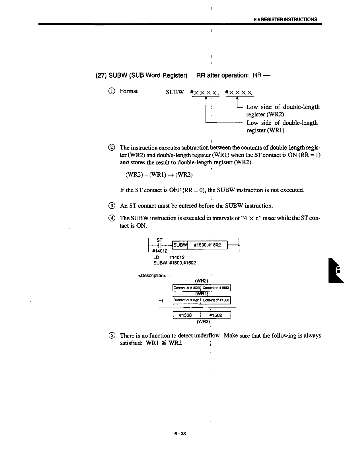
;
REGISTER
6.5
INSTRUCTIONS
(27)
SUBW
Format
®
(D
The
ter
and
If
(|)
An
The
®
tact
(SUB
instruction
(WR2)
stores
(WR2)
the
ST
ST
contact
SUBW
ON.
is
-
contact
Word
Register)
SUBW
executes
double-length
and
the
result
(WR1)
is
must
instruction
#X
subtraction
register
to
double-length
(WR2)
»
—
(RR=0),
OFF
entered
be
executed
is
RR
X
X X
before
in
operation:
after
,
between
(WR1)
register
the
SUBW
the
intervals
#X
X X
T
the
when
(WR2).
instruction
SUBW
of
RR
—
X
side
Low
register
side
Low
register
contents
the
instruction.
“4
of
ST
contact
msec
n”
x
of
double-length
(WR2)
of
double-length
(WR1)
double-length
ON
is
executed.
is
not
while
the
(RR
ST
regis¬
=1)
con¬
®
<Description>
There
is
satisfied:
|
!
no
WR1
j
|
#14012
LD
SUBW
-)
function
£
L
#1502
of
#1503
detect
#1500,
(WR2)
Contortof*1502
#1503;
(WR1)
Contont
(WR2)
underflow.
1
#1502
t|
|
SUBWj
-
#14012
#1500,
Icontent
]con1«mot»150li
I
to
WR2
#1502
j
j
qf
H
#1500
Make
t
1
j
|
sure
that
the
following
is
always
6-33
Page 72

(28)
MULW
(T)
Format
(MUL
Word
Register)
MULW
after
RR
#XXXX,
operation:
#X
XXX
RR
0
(D
d)
G)
(D
instruction
The
(WR2)
result
(WR1)
the
If
ST
An
MULW
The
is
tact
If
overflow
1).
=
The
lower
executes
the
and
double-length
to
ST
contact
(R2)
X
contact
register
-4
is
OFF
be
must
(WR2)
instructionisexecuted
ON.
occurs,
one
word
in
other
is
multiplication
(Rl)
when
(RR
words,
(WR2).
0),
=
before
the
to
if
register
entered
stored
of
ST
the
MULW
the
the
intervals
in
the
result
register.
L
the
contents
contact
instruction
MULW
of
exceeds
Low
register
—
Register
is
ON
instruction.
“4
n”
X
FFFH,
side
of
(WR2)
(Rl)
double-length
of
not
is
msec
“1”
1)
=
executed.
while
is
(RR
double-length
register
and
set
the
to
stores
ST
RR
the
con¬
(RR
|—5h
-
I
#14012
LD
MULW
<Description>
X)
jMULWj
-
-
#14012
#1500,
#1502
[content
#1503
l
6-34
#1500,
of
*15031
#1502
(WR2)
Content
[content
(WR2)
of
(R1)
of
#1502
H
«15(g|
*150o|
Page 73
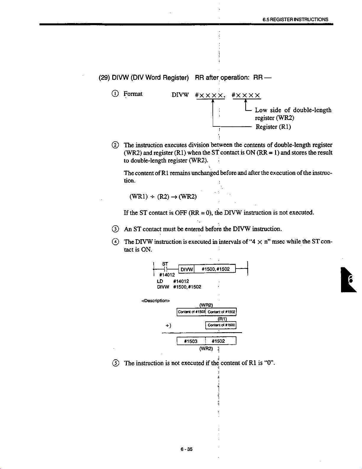
REGISTER
6.5
INSTRUCTIONS
(29)
DIVW
Format
0
(2)
The
(WR2)
to
The
tion.
If
(D
An
The
0
tact
(DIV
Word
Register)
instruction
register
and
double-length
Rl
ST
contact
contact
ON.
H-
of
(R2)
must
instruction
content
(WRl)
the
ST
DIVW
is
DIVW
executes
(Rl)
register
remains
(WR2)
is
OFF
be
RR
#x
division
when
(WR2).
unchanged
(RR
=
entered
executed
is
after
X X
between
the
ST
0),
before
in
operation:
X,
#X
l
t
the
contact
before
:
the
DIVW
DIVW
the
intervals
RR
X
X
X
L
Low
register
Register
contents
(RR
is
ON
and
after
instruction
instruction.
“4
of
—
side
(WR2)
double-length
of
1)
=
execution
the
is
msec
n”
x
double-length
of
(Rl)
and
stores
of
not
executed.
while
the
the
the
register
result
instruc¬
con¬
ST
®
instruction
The
|
Hh
—
I
#14012
LD
DIVW
<Description>
is
IdivwI
—
-
#14012
#1500,
Content
|
|
not
#1500,
-
#1502
(WR2)
*1503
of
#1503
(WR2)
executed
Content
Coniait
|
I
if
#1502
(R1)
#1502
;|
the:
content
i.
H
ol
»1S02
1
of
»1SOo]
]
of
Rl
is
k
“0”.
6-35
Page 74

(30)
INRW
Format
©
(Increment
Word
INRW
Register)
#
xxxx
RR
after
operation:
RR
—
(31)
The
©
contact
An
©
The
©
tact
There
©
returns
DCRW
The
©
ception
There
©
returns
instruction
(RR
is
ON
instruction
ff
—
-
#14012
I
LD
INRW
function
no
OH.
instruction
the
function
no
FFFH.
must
ST
contact
INRW
ON.
is
I
is
to
(Decrement
DCRW
that
is
to
adds
“+1
1).
=
be
I'NRwj
-
'
#14012
#1500
to
Word
DCRW
to
the
to
”
entered
is
executed
#1500
L
detect
overflow.
Register)
basically
is
instruction
underflow.
detect
content
before
in
intervals
the
adds
of
the
If
RR
same
side
Low
double-length
the
INRW
the
after
“-1”.
If
instruction.
“4
of
result
operation:
the
as
the
result
double-length
of
n”
msec
X
of
operation
INRW
of
operation
register
while
exceeds
RR
—
instruction
exceeds
register
when
the
with
the
ST
FFH,
the
OH,
ST
con¬
it
ex¬
it
(32)
(33)
CLRW
The
©
ception
to
CMRW
The
©
ception
ter.
(Clear
“0”.
Word
CLRW
(Complement
CMRW
instruction
the
that
instruction
the
that
Register)
CLRW
Word
CMRW
•
6-36
basically
is
instruction
Register)
basically
is
instruction
after
RR
the
same
the
clears
RR
the
same
reverses
operation:
the
as
content
after
the
as
content
the
INRW
INRW
instruction
double-length
the
of
operation:
instruction
the
of
RR
—
with
register
RR
—
with
double-length
ex¬
the
ex¬
the
regis¬
Page 75

6.5
REGISTER
•i
INSTRUCTIONS
(34)
CORW
Format
®
The
©
is
If
tent
(D
After
main
@
An
(
1
)
The
tact
(Coincide
instruction
(RR
ON
WR1
=
WR1
*
the
ST
contact
of
RR
the
executionofthe
unchanged.
contact
ST
CORW
is
ON.
Word
CORW
executes
1),
and
=
WR2Z1=1
WR2
remains
Z1
is
OFF
unchanged.
be
must
instruction
Register)
xx,
#xx
comparison
“0”or‘T’.to
sets
=0
(RR=0),
CORW
entered
executedinintervals
is
the
instruction,
before
after
RR
.
#x
between
Z1
according
CORW
the
CORW
operation:
x
x x
U
Double-length
(WR2)
Double-length
(WR1)
1
WR
and
to
instruction
the
contents
instruction.
of
“4
n”
X
WR2
the
is
not
msec
RR
0
when
result
executed.
of
WR1
while
register
register
the
ST
contact
of
comparison.
The
and
WR2
the
ST
con¬
re¬
con¬
ST
#14012
LD
CORW
OUT
CORW
#14012
#1500,
#14123
#1500,
#1502
Z1
#1502
#14123
#1500=#1502
#1500
*
.
I
]
ii
i
.
<i
i
#1502
....
...
.
is
Z1
iscleared.
Z1
set
k
6-37
Page 76
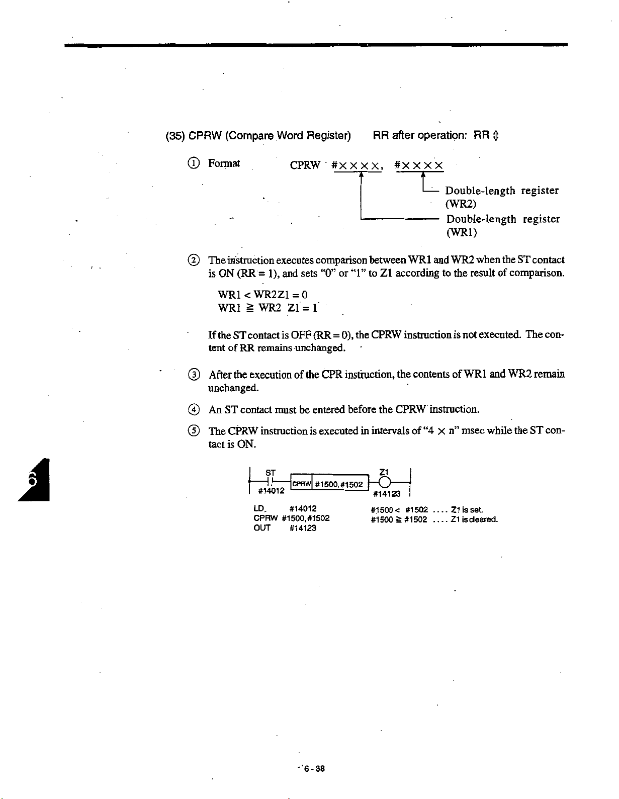
(35)
CPRW
(J)
Format
(Compare
Word
CPRW
Register)
#XXXX,
RR
operation:
after
#XXXX
RR
0
(D
The
is
If
tent
(D
After
unchanged.
An
©
(D
The
tact
instruction
(RR
ON
WR1
<
S
WR1
ST
the
of
RR
the
ST
contact
CPRW
ON.
is
contact
execution
executes
1),
and
=
WR2Z1
WR2
Zl
is
remains
must
instruction
comparison
sets
“0”
=0
1
=
(RR=0),
OFF
unchanged.
the
CPR
of
be
entered
executed
is
between
or
to
Z1
“1”
the
CPRW
instruction,
before
the
intervals
in
U
and
WR
1
according
instruction
the
contents
CPRW
instruction.
“4
of
Double-length
(WR2)
Double-length
(WR1)
when
WR2
result
the
to
executed.
is
not
and
WR1
of
while
msec
n”
x
register
register
the
ST
contact
of
comparison.
The
remain
WR2
the
ST
con¬
con¬
LD.
CPRW
OUT
[#1500,#1502~f—
CPRW
#14123
#14012
#1500,
#14123
-'6-38
#1502
#1500
#1500
Q
-
I
set
<
g
#1502
#1502
....
..
is
Z1
is
Z1
.
.
cleared.
Page 77
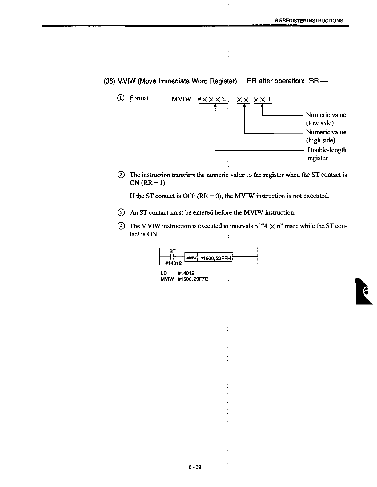
(36)
MVIW
(Move
Immediate
Word
Register)
RR
after
6.5
REGISTER
operation:
INSTRUCTIONS
RR
—
©
(D
©
©
Format
The
instruction
(RR=1).
ON
the
If
An
ST
The
MVIW
is
tact
ST
contact
contact
ON.
MVIW
transfers
is
OFF
be
must
instruction
ST
#14012
#14012
LD
#1500,20FFE
MVIW
#XXXX,
numeric
the
(RR=0),
entered
executedinintervals
is
MVIW
#1500,20FFH
the
before
XX
value
MVTW
the
XXH
the
to
instruction
MVIW
of
register
when
instruction.
“4
msec
n”
x
is
Numeric
(low
Numeric
(high
Double-length
register
the
ST
executed.
not
while
the
value
side)
value
side)
contact
ST
is
con¬
6-39
I
:i
'I
il
<
J
Page 78

(37)
DSTW
(J)
Format
(Data
Store
Word
DSTW
Register)
ixxxx,
RR
#X
after
X
operation:
X,
X
X
RR
—
X
X
X
J
®
(X)
0
Register
Numeric
Register
The
instruction
when
the
register
the
of
instruction.
the
ST
If
ST
An
The
tact
WR1
Value
WRl
contact
DSTW
is
ON.
D15
B
0
0
executes
ST
contact
(WR1)
contact
is
ST
|
(-
—
#14012
must
instruction
D13
D14
B B
B
0 0
0
0
0
the
between
AND
(RR=1)
ON
is
remains
OFF
DSTW
j
1-1
-
LD
DSTW
---
entered
be
is
D12
0
unchanged
(RR
0),
=
1
#1502,
#1500,
#14012
#1502,
#1500,
before
executed
D10
D11
B B
1
1
B
B
the
in
content
and
stores
before
DSTW
OFOFH
H
OFOFH
the
DSTW
intervals
D9
D8
B B B
B
1
1
B
B
instruction
of
D7
0
0
t
of
WR1
result
the
after
and
instruction.
“4
D6
0
0
msec
n”
X
D5
B
0
0
Numeric
Register
Register
the
and
to
is
D4
B
0
0
numeric
WR2.
the
executionofthe
not
executed.
while
D3
B B
1
B
The
the
D2
1
B
value
(WR2)
(WR1)
value
content
ST
con¬
D1
B
1 1
B B
DO
B
B:
“0”
of
“1”
6-40
Page 79

CONTROL
6.6
!>
INSTRUCTIONS
6.6
CONTROL
The
control
(1)
NOP
©
©
(2)
MCR
©
©
INSTRUCTIONS
NOR
is
of
Control)
MCR
or/and
of
“RR
are
described
executed
remains
RR
executes
X2
contacts
0”.
=
instructions
(No
Operation)
Format
No
operation
The
content
tion.
(Master
Format
The
instruction
ON
the
state
(RR=1).
XI
are
If
the
below.
RR
after
and
the
program
unchanged
after
RR
the
sequence
are
OFF
operation:
!
advancestothe
before
operation:
ladder
i
(RR=0),
and
when
RR
after
RR
the
—
next
the
execution
—
the
bothXIand
ladder
is
step.
the
of
X2
executed
instruc¬
contacts
to
END
in
It
is
®
tions
Whenatimer
®
when
Even
©
the
*1
-
#14001
X3
#
14003
X4
#
14004
#14005
LD
AND
MCR
LD
OUT
LD
OUT
LD
OUT
END
possible
(max.
the
MCR
the
if
self-holding
circuit
output
#14002
#14001
#14002
#14003
#14010
#14004
#14011
#14005
#14012
to
enter
levels).
7
-
another
—
IMCRI
Z1
and
=
X2
relays
conlacts
#1$10
#14011
6—
#14012
<Description>
If
X1
internal
MCR
X1
HHHl
,
Z1
instruction
instructionisincludedinthe
instruction
is
OFF
is
circuit
when
OFF.
is
formed
the
|
|
MCR
X2
—
X5
are
Z2,
and
between
instruction
Z1
X3
II
O
-
Z2
X4
Z3
OFF,
“0*
Z3.
between
MCR
-
output
is
instruction,
the
the
MCR
is
OFF.
to
MCR
and
the
and
the
END
timer
END
instruc¬
is
cleared
instructions,
I
6-41
.
Page 80
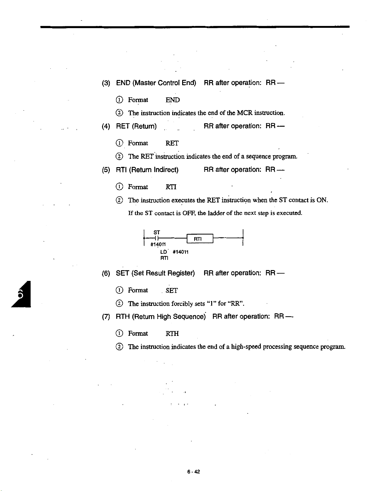
(3)
END
(Master
Control
End)
RR
after
operation:
RR
—
(4)
(5)
(6)
®
©
RET
©
®
RTI
®
©
SET
Format
The
instruction
(Return)
Format
The
RET
(Return
Format
instruction
The
If
the
(Set
instruction
Indirect)
ST
contact
ST
-ih
#14011
LD
RTI
Result
END
indicates
RET
indicates
RTI
executes
OFF,
is
1
#14011
Register)
the
RTI
the
the
end
RR
the
RR
RET
ladder
RR
the
of
operation:
after
end
operation:
after
instruction
of
h
operation:
after
MCR
of
a
sequence
the
next
instruction.
RR
—
program.
RR
—
the
when
step
is
RR
ST
executed.
—
contact
is
ON.
(7)
©
@
RTH
®
©
Format
The
instruction
(Return
Format
instruction
The
SET
High
RTH
forcibly
Sequence)
indicates
sets
the
“1”
end
RR
“RR”.
for
after
high-speed
of
a
operation:
processing
RR
—
sequence
program.
6-42
Page 81

(8)
JMP
(Jump)
RR
after
operation:
RR
CONTROL
6.6
—
INSTRUCTIONS
©
©
©
Format
instruction
The
1).
If
the
With
=1.
RR
ST
the
contact
ST
If
#14000
LD
JMP
JMP
JMP
XXX
I
executes
is
OFF
#14000
012
instruction,
jump
(RR
JMP012
-f
ADR
the
to
0),
=
012
states
Label
ADR012
the
the
ladderofthe
|
=
-
of
output
number
when
coils
of
jump
the
next
to
up
destination
ST
contact
executed.
is
step
retained
are
ADR
(RR
ON
is
=
when
(9)
ADR
©
©
©
the
With
(Address)
Format
The
instruction
JMP
The
by
fied
MCR
and
the
instruction,
ADR
indicates
ADR
JMP
and
however,
RR
XXX
destination
the
instructions
instructions
ADR
6-43
after
Label
are
the
operation:
1
number
i
of
always
given
I
4
:
output
jump
used
in
coil
RR
called
in
pairs.
a
pair
state
—
up
must
is
by
The
not
the
label
be
the
retained.
instruction.
JMP
numbers
same.
I
speci¬
Page 82
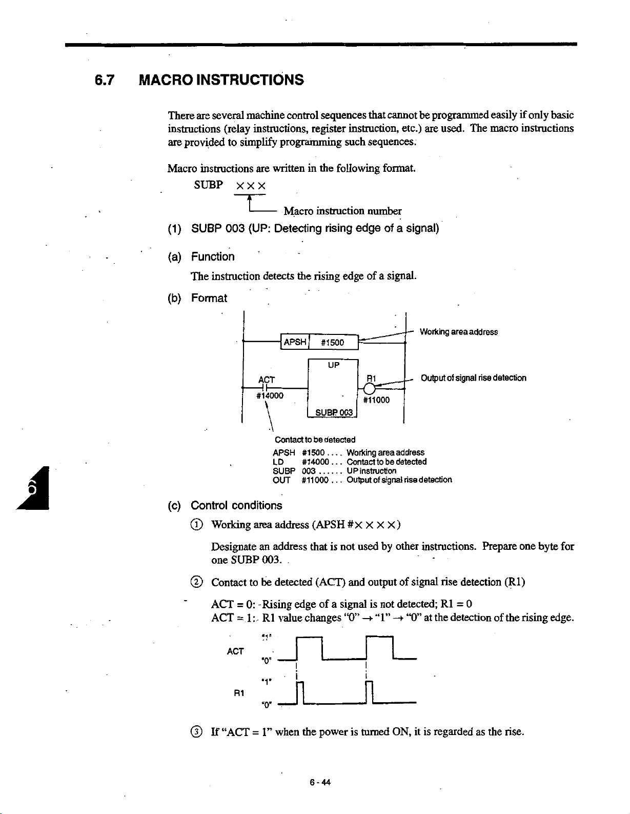
6.7
MACRO
INSTRUCTIONS
There
instructions
are
Macro
(1)
(a)
(b)
several
are
provided
instructions
SUBP
SUBP
Function
instruction
The
Format
(relay
simplify
to
XXX
003
machine
instructions,
are
(UP:
control
programming
written
Macro
Detecting
detects
-|APSH|
3P
#14000
sequences
register
the
in
instruction
rising
the
rising
#1500
SUBP
instruction,
such
following
edge
UP
003
cannot
that
sequences.
format.
number
of
edge
signal.
a
of
R1
#11000
etc.)
signal)
a
be
programmed
used.
are
Working
Output
area
of
signal
easily
The
macro
address
rise
if
instructions
detection
only
basic
(c)
Control
(D
Working
Designate
one
Contact
©
ACT
ACT
If
©
conditions
area
SUBP
to
0:
=
1
:
=
:
-
-
“ACT
=
detected
be
to
Contact
..
of
.
.
is
a
Working
Contact
UP
Output
.
.
#X
not
signal
“0”
APSH
LD
SUBP
OUT
address
address
an
003.
be
detected
-Rising
value
Rl
#1500.
#14000
003
#11000
(APSH
that
(ACT)
edge
changes
_n__n_
!
_
n
the
1”
when
power
instruction
X
used
and
output
is
-*•
i
n
is
turned
area
to
of
X
“1”
be
signal
by
not
address
detected
rise
)
X
other
of
signal
detected;
“0”
—
ON,
it
detection
instructions.
detection
rise
0
Rl
=
detection
the
at
regarded
is
Prepare
of
the
as
(Rl)
the
rise.
one
byte
rising
for
edge.
6-44
Page 83
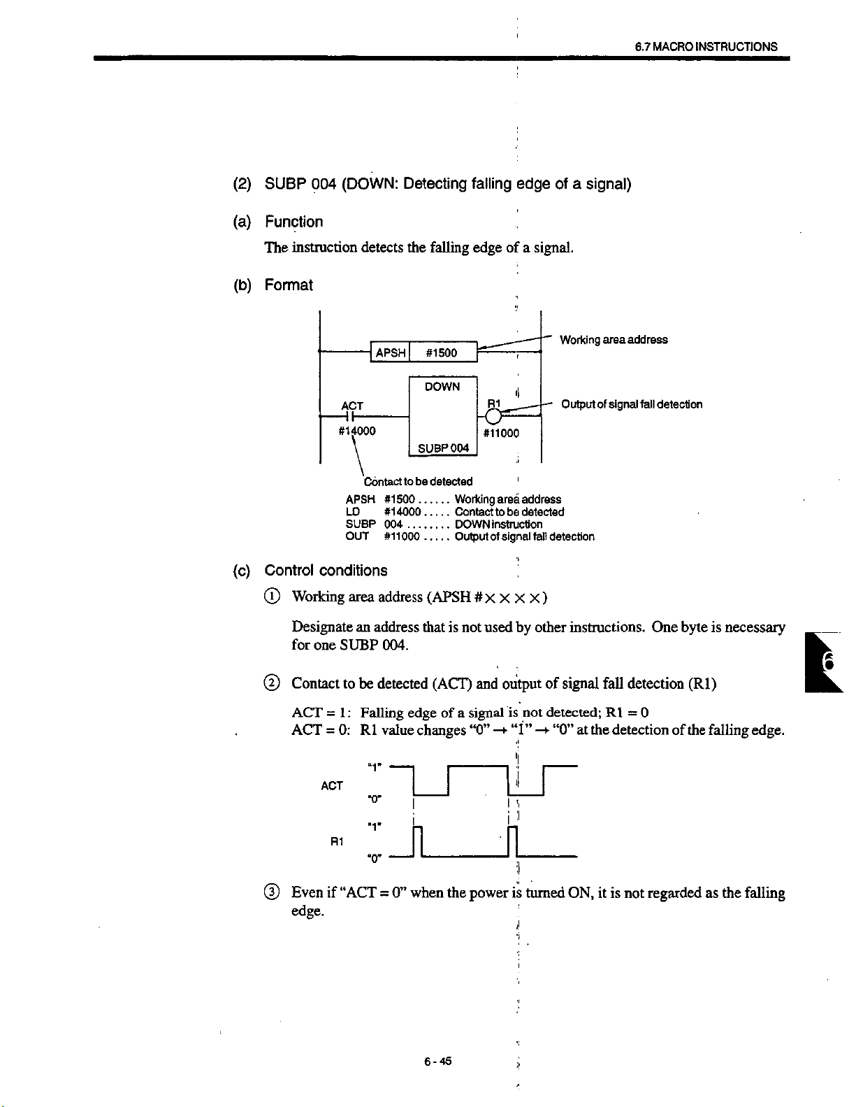
MACRO
6.7
:
INSTRUCTIONS
(2)
(a)
(b)
(c)
SUBP
004
Function
The
instruction
Format
Control
(DOWN:
detects
APSH
ACT
#14000
Contact
APSH
LD
SUBP
OUT
conditions
Detecting
the
|
SUBP
be
to
#1500.
#14000
.
004
..
#11000
falling
#1500
DOWN
004
detected
Working
Contact
DOWN
Output
falling
edge
of
-5='
#11000
area
be
to
instruction
signal
of
edge
a
signal.
address
detected
fall
a
signal)
of
Working
Output
detection
area
of
address
signal
detection
fall
Working
©
Designate
for
Contact
©
ACT
ACT
Even
©
edge.
one
=
=
ACT
if
address
area
an
SUBP
be
to
1
:
Falling
0:
Rl
address
detected
*r
004.
value
that
edge
changes
.ÿ-THLr
i
R1
:
“ACT
“O’
n n
when
0”
=
(APSH
is
(ACT)
of
a
the
#
X
used
not
and
signal
“0”
power
X X
output
is
“1”
—
I
is
X
by
other
not
—
•I
’i
turned
<'
)
instructions.
signal
of
detected;
“0”
at
ON,
One
detection
fall
0
Rl
=
the
detectionofthe
is
it
regarded
not
byte
(Rl)
is
necessary
falling
the
as
falling
L
edge.
6-45
.1
Page 84
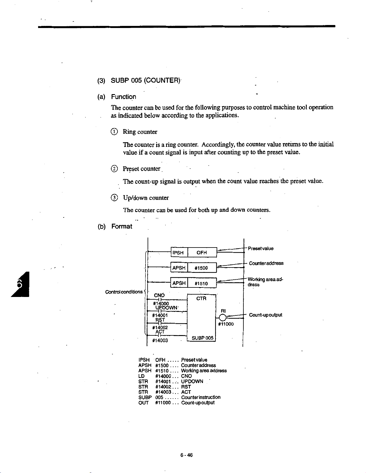
(3)
(a)
SUBP
005
Function
(COUNTER)
A
(b)
The
as
(T)
(2)
©
Format
Control
counter
indicated
counter
Ring
counter
The
if
value
Preset
The
count-up
Up/down
The
counter
conditions
be
can
below
counter
a
count
used
according
a
ring
is
signal
signal
counter
be
can
CNO
_
"#14000
UfiOOWN-
#14001
mi
#14902
#14003
used
]
IPSH
~j
APSH
for
the
to
counter.
is
input
is
output
for
[
|
following
the
applications.
Accordingly,
after
when
both
up
OFH
#1500
#1510
CTR
005
SUBP
purposes
counting
the
count
down
and
\
Ri
#11000
control
to
the
counter
the
to
up
value
counters.
Preset
Counteraddress
Working
dress
Count-up
machine
value
preset
reaches
value
area
ad¬
output
returns
value.
the
preset
operation
tool
the
to
value.
initial
IPSH
APSH
APSH
LD
STR
STR
STR
SUBP
OUT
.
OFH
#1500
#1510
#14000
#14001
#14002...
#14003...
005
#11000
Preset
Counter
Working
.
CNO
.
.
.
UPDOWN
.:.
RST
ACT
Counter
Count-up
..
.
6-46
value
address
area
address
'
instruction
output
Page 85

6.7
MACRO
INSTRUCTIONS
(c)
Control
Designation
©
Designate
To
instruction.
are
Example:
With
Even
Designation
©
Designate
If
“APSH
for
Designation
©
conditions
of
the
designate
If
usedasthe
PUSH
the
designation
only
the
#
1
counter
one
of
500”
if
the
of
preset
preset
variable
a
PUSH
the
preset
#1550
byte
counter
counter
designated,
is
address.
working
(IPSH
value
value
directly.
value,
instruction
value.
indicated
used,
is
address
address.
area
XX)
the
use
is
i
above,
#1551,
(APSH
continuous
address
PUSH
used,
two
not
must
#
X
(APSH
instruction
the
contents
bytes
be
X X
X
two
bytes
#
X XXX
of
#1550
used
)
(#1500
of
for
)
the
other
instead
of
designated
#1551
and
instructions.
and
501
#1
IPSH
the
address
used.
are
)
used
are
Designate
for
If
dress
@
Designation
CNO
CNO
Designation
©
UPDOWN
UPDOWN
one
two
or
for
=
=
The
The
The
an
SUBP
more
each
of
0:
Counting
Counting
1:
of
=
initial
initial
=
initial
address
005.
SUBP
SUBP
initial
begins
up/down
0:
1:
counter
Up
value
value
Down
valueisthe
is
that
not
instructions
005
instruction.
005
(CNO)
value
begins
counter
“0”
is
is
“1”
counter
preset
usedbyother
*
“0”.
with
with
“1”.
(UPDOWN)
i
1
CNO
with
CNO
with
;i
value.
i|
are
(0,
(1,
=
=
instructions.
used,
it
2,
1,
2,
3,
0.
1.
is
necessary
n)
n)
One
to
is
byte
necessary
designate
an
ad¬
£
6-47
Page 86

G)
Reset
(RST)
©
RST
=
RST=1:
R1
Counted
Count
ACT
=
ACT
=
the
content
If
the
following
in
UP
counter:
DOWN
ACT
Reset
0:
Reset
cleared
is
(ACT)
signal
The
0:
1:
Counts
counter:
“1"
xi_n_
*0"
released
to
value
counter
at
the
of
manner.
The
The
is
a
’
COUNT
“0”.
is
reset
does
rising
the
counter
value
value
reduced
normal
initial
the
to
not
operate.
(“0”
edge
is
greater
returns
reducedateach
is
the
to
counter.
COUNT
than
the
to
preset
value.
Contents
“1”).
-+
the
initial
input
value.
preset
value
After
R1
of
value,
of
that
remain
the
at
ACT
the
unchanged.
the
counter
first
until
the
counter
ACT
count
operates
signal.
value
operates
as
©
Count-up
counter:
Up
.
Upon
Upon
.
counter:
Down
output
counting
counting
(Rl)
‘T”
“1”
CNO
down
CNO
down
is
is
=
to
=
to
set
set
0
“0”
1
“1”
for
for
.'
upon
Rl
according
Rl
counting
the
to
.
:
.
the
to
up
following
preset
condition.
value.
6-48
Page 87

!
{4)
(a)
(b)
SUBP
006
Function
This
instructionisused
the
It
has
•
•
•
following
Determination
Calculation
tion
Calculation
to
steps
Format
(ROTATION)
control
to
functions:
for
shorter-path
the
of
number
the
of
position
the
position
one
of
one
step
rotating
when
between
steps
step
before
J
4
!
units
such
1
determining
the
present
before
the
I
the
target
as
turrets,
the
position
target
position
MACRO
6.7
ATCs,
direction
position
INSTRUCTIONS
and
rotary
rotation
of
and
the
target
the
number
or
tables.
posi¬
of
Control
conditions
RNO
#14000
IP
#14001
DIR
#14002
#14003
INC
#14004
ACT
#14005
APSH
APSH
APSH
IPSH
LD
STR
STR
STR
STR
STR
SUBP
OUT
APSHi
APSH
APSH
IPSH
#1510
#1520
#1530
10H
ROT
R1
-o
#11000
Calculation
Target
Present
Number
result
position
position
positioning
of
address
i
006
SUBP
____
____
#1510
#1520
#1530
10H
#1
4000
#1
4001
#1
4002
#14003
#14004...
#14005...
006
000
#11
Calculation
—
Target
Present
Number
Position
.
..
.
.
Position
.
..
.
Direction
Target
..
.
Position
Execution
ROT
..
instruction
Output
......
.
1
t[
4
address
result
position
address
position
address
of
number;
data;
of
positionorposition
numberorthe
direction
of
rotating
1
byte
rotation;
(
unit
from
of
or
fixed
rotation
positioning
“O’
2
number
from
or
bytes
or
shorter
step
1
points
*1
before
of
steps
’
path
the
address
address
target
points
position
in
one
turn
l
6-49
:i
i
Page 88

(c)
Control
conditions
Designation
®
The
the
tion
designated
Designation
©
Designate
where
Designation
®
Designate
address
Designation
©
RNO
RNO
Designation
©
instruction
ROT
number
one
step
the
of
0:
=
:
1
=
calculation
of
of
steps
before
address.
of
target
the
address
command
T
the
of
the
address
the
counter
of
the
Position
Position
the
of
calculates
the
of
position
the
target
position
where
is
output
present
where
where
value
initial
number
number
number
storing
result
the
position.
address
the
target
from
position
the
present
the
position
of
the
the
of
the
of
bytes
of
addresses
number
one
step
The
(APSH
position
NC.
die
address
position
position
rotating
rotating
of
the
of
steps
before
result
#
X
is
(APSH
the
of
rotating
number
unit
begins
begins
unit
position
(APSH
the
the
of
XXX
stored:
#X
data
#
X
rotating
position,
target
calculationisstored
)
example,
for
X)
X
X
stored:
are
unitisstored.
the
rotating
of
with
“0”.
with
“1”.
(BYT)
data
X
unit
for
X
)
X
or
rotate,
the
posi¬
should
in
the
address
example,
(RNO)
unit
the
the
BYT
BYT
Designation
®
DIR
DIR
Designation
®
POS
POS
Designation
©
INC
INC
Binary
0:
=
1
:
Binary
=
of
Determination
0:
=
Rotation
:
Determination
1
=
of
0:
The
=
:
1
The.
=
position
of
0:
The
=
:
The
1
=
1
byte
bytes
2
whether
or
direction
operation
number
of
position
one
or
the
position
position
number
of
not
shorter-path
made.
is
not
only
is
made.
is
conditions
to
steps
the
number
or
before
step
number
steps
is
is
number
rotation
FOR
the
(POS)
the
or
target
of
steps
the
target
the
number
position
calculated.
calculated.
direction
direction.
is
the
to
position
position.
of
steps
determined
is
calculated.
which
(INC)
is
(DIR)
one
6-50
Page 89

MACRO
6.7
.1
•j
INSTRUCTIONS
Execution
®
ACT
ACT
Output
©
R1
Rl
=
=
FOR
REV
command
ROT
0:
=
R1
ROT
1:
=
(Not
rotation
of
The
0:
The
1:
(forward)
(reverse)
3,
2\REV
1
instruction
not
is
instruction
by
rotation
rotadon
direction
direction
4
8
A
Index
Position
(ACT)
influenced.
rising
the
direction
direction
direction
The
reference
The
reference
,5
6
FOR/.
i
is
not
is
executed.
edge
(Rl)
direction
direction
7,
8
FOR
1
Index
executed.
the
of
is
'‘forward”.
‘‘reverse”.
is
which
in
the
index
to
which
in
index
the
to
6
REV/
2
A
Position
signal.)
the
position.
the
position.
5
4
3
number
number
increases
decreases
in
in
If
•
lated
the
the
result
number
while
the
of
of
steps
present
calculation
6-51
position
the
to
position
is
“0”.
is
equal
1
ti
1
J
I
;
one
to
step
the
before
target
the
target
position
position
(POS
is
calcu¬
INC
1,
=
1),
=
k
Page 90

(5)
(a)
SUBP
007
Function
instruction
This
table.
_
Conversion
(CODE
#xxxx
Conversion
#xxxx
CONVERT)
converts
standard
the
data
[
o
data
jjtoutaddre
data
address
I]
by
DATA
using
TABLE
address
Stan
the
conversion
xxxx
No.
in
0_
_L
2
3
4_
n
Table
table
created
Conversion
_
Data
3A
on
the
PLC
BYT
®
If
instruction
output
The
BYT
®
In
=
“3”
is
start
=
case,
this
Conversion
0
specified
stores
address.
of
the
1
the
iXXXX
Conversion
#xxxx
for
the
table
size
of
standard
I
output
data
El
conversion
the
“third
Oth.
is
conversion
the
address
data
3
1
address,
data”
from
DATA
Stan
standard
the
start
data
table
TABLE
address
xxxx
data
address
table
the
of
should
BYT-1
n-1
be
No.inTable
BYT-0
0
1
2
Hil
n
1
0.
2.
3_
_Q_
as
the
to
even
an
Conversion
Data
shown
above,
conversion
number
3A
4B
of
the
data
bytes.
6-52
Page 91

J
(b)
Format
Control
conditions
<
BYT
n
#14000
911
#14001
#14002
IPSH
APSH
APSH
TPSH
#1500
#1510
#9000
COD
iRpnn7
fii
14H
i
i
J
t
<5
#14010
Number
of
items
data
Conversion
data
address
Conversion
address
The
number
containing
data
MACRO
6.7
conversion
standard
output
data
of
PLC
conversion
the
INSTRUCTIONS
table
PLC
9000
IPSH
APSH
APSH
TPSH
LD
STR
STR
SUBP
OUT
-20H
-30H
-40H
:
AH
1
—
12BH
-3CH
Table
14H
#1500
#1510
#9000
#14000
#14001
#14002...
007
#14010...
Conversion
in
No.
Table
0
1
2
17
18
19
____
____
Size
____
Conversion
Conversion
PLC
Data
...
Reset
...
Execution
COD
Erroroutput
>
Conversion
_
Data
20H
30H
1AH
2BH
3CH
of
conversion
standard
data
table
number
data
in
the
instruction
.i
table
data
?
.1
data
data
output
containing
1
table;
,
(number
table
address
address
the
byte,
conversion
bytes
2
of
bytes)
data
!
I.
6-53
'!
'!
H
Page 92
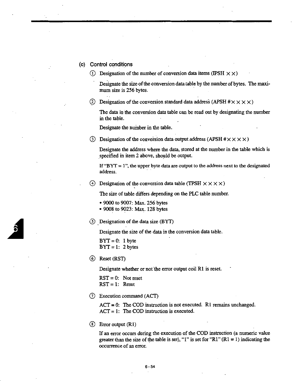
(c)
Control
conditions
(D
Designation
Designate
mum
@
Designation
The
in
Designate
Designation
©
Designate
specified
If
address.
Designation
©
The
9000
•
9008
•
data
the
“BYT
size
size
in
table.
in
=
of
to
to
of
the
size
256
is
of
the
the
number
of
the
address
item
1”,
the
of
table
9007:
9023:
the
number
the
of
conversion
bytes.
the
conversion
conversion
the
in
conversion
the
where
above,
2
byte
upper
the
conversion
differs
Max.
Max.
depending
256
128
conversion
of
standard
data
table
table.
data
data,
the
should
bytes
be
data
data
bytes
data
output
are
table
on
table
data
can
be
stored
output.
output
(TPSH
the
items
data
by
address
read
address
the
at
the
to
PLC
table
(BPSH
the
number
(APSH
by
out
(APSH
number
address
X X
X
number.
XX)
bytes.
of
#
X
X
X X
designating
#X
XXX
the
table
in
next
X)
the
to
maxi¬
The
)
the
number
)
which
designated
is
1
Designation
©
Designate
BYT
BYT
Reset
©
Designate
RST
RST=1:
Execution
©
ACT
ACT
Error
®
If
greater
occurrence
an
0:
=
1:
=
(RST)
0:
=
0:
=
1:
=
output
error
than
the
data
of
the
size
of
1
byte
bytes
2
whether
Not
or
reset
Reset
command
COD
The
COD
The
(Rl)
of
the
an
during
size
error.
occurs
(BYT)
size
the
data
the
not
(ACT)
instruction
instruction
the
table
the
of
the
conversion
in
error
output
not
is
is
executed.
execution
set),
is
table.
data
is
reset.
R1
coil
executed.R1remains
COD
set
for
instruction
(Rl
“Rl”
of
“1”
the
is
unchanged.
(a
numeric
1)
indicating
=
value
the
6-54
Page 93

MACRO
6.7
T
INSTRUCTIONS
{6)
(a)
(b)
SUBP
Function
instruction
The
bytes
Number
same
the
repeatedly
Format
conditions
Control
(PATTERN
009
beginning
Write
of
by
bytes
number
is
‘
writes
with
pattern
which
written
CLEAR)
the
same
the
designated
00
I
_
_
20
1
I
IPSH
IPSH
APSI-#1500
numeric
L
.
value
address.
OH
14H
i
t
repeatedly
x
*
*
1
,1
XJ
by
the
pattern
Write
Start
for
of
same
address
writing
Number
the
repeatedly
designated
00
00
00
(0
>
00
oo
00
00
by
bytes
numberiswritten
which
number
20
BYTES
of
IPSH
IPSH
APSH
LD
SUBP
OUT
ACT
II
#14000
OH
14H
#1500
#14000...
#009
#14010...
PCLR
#14010
SUBP
____
.
pattern
Write
Number
Start
address
Execution
PCLR
Output
1
009
;
of
bytes
for
command
completion
of
which
by
writing
of
the
write
same
of
Output
numberiswritten
completion
il
1
write
of
repeatedly
I.
6-55
5
Page 94

(c)
Control
conditions
(J)
Designation
Designate
To
instead
Designation
0
ly
Designate
Designation
®
Designate
Pattern
bytes.
(f)
Execution
ACT
ACT
Output
0
of
the
designate
of
using
of
(IPSH
XX)
the
of
the
clearisexecuted
command
The
0:
=
The
1:
=
of
completion
the
pattern
variable
a
the
the
number
number
the
start
PCLR
PCLR
write
pattern
to
be
pattern,
instruction.
IPSH
bytes
of
address
start
address
beginning
(ACT)
instruction
instruction
write
of
written.
use
bytes
of
to
writing.
of
(Rl)
(IPSH
the
by
clear
writing
of
with
executed.
is
is
not
X)
X
PUSH
which
the
the
pattern.
(APSH
this
address
executed.
instruction
number
same
#
X X
by
the
designate
to
is
written
)
X
X
designated
the
address
repeated¬
number
of
R1
Rl
=
=
0:
1:
Writing
Writing
completed
not
completed
6-56
Page 95

MACRO
6.7
INSTRUCTIONS
(7)
(a)
(b)
SUBP
011
Function
instruction
The
checked
an
If
error
Format
Control
conditions
(PARITY
(1-byte
detected,
is
APSH
LD
STR
STR
SUBP
OUT
CHECK)
executes
data).
an
OE
#ÿ0
#UM1
#14002
....
#1500
#14000
#14001
#14002
011
#14010...
parity
check
error
output
APSH|
SUBP
Check
data
Designationofparity
.
.
Reset
.
.
Executioncommand
.
.
instruction
PARI
Erroroutput
(even
given.
is
#1500
PARI
011
address
;l
parity
R1
#14010
scheme
odd
or
Check
(even/odd)
parity)
data
the
for
address
datatobe
(c)
Control
Designation
®
Designate
Parity
(|)
Designation
OE
OE
(D
Reset
RST
RST
@
Execution
ACT
ACT
(D
Error
If
for
conditions
check
Even
0:
=
Odd
1
:
=
(RST)
0:
=
:
1
=
0:
=
1
:
=
output
result
the
(Rl~1).
“Rl”
check
of
address
the
made
is
parity
of
parity
parity
Error
output
Error
output
command
The
PARI
The
PARI
(Rl)
of
parity
address
data
where
byte
for
1
scheme
check
check
R1
is
R1
is
(ACT)
instruction
instruction
does
check
the
(8
(OE)
not
reset.
(APSH
to
data
bits)
!:
;!
reset.
not
is
executed.
is
i
meet
not
;
!
#
be
checked
data.
of
X X
)
X
X
stored.
are
executed.R1remains
designated
the
parity
unchanged.
scheme,
“1”
is
set
6-57
Page 96

(8)
(a)
SUBP
014
Function
(DATA
CONVERT)
(b)
instruction
The
data.
Format
Control
conditons
APSH
APSH
LD
STR
STR
STR
SUBP
OUT
converts
#14000
-W-
#14001
#14002
#14003
#1500
#1510.
#14000
#14001
#14002...
#14003...
014
#14010
.
the
3d
...
...
binary
datatothe
APSH|
APSH|
]
DCNV
SUBP
.
Conversion
Converted
1-byteor2-byte
BCD
BIN
-+
Reset
Execution
instruction
DCNV
Erroroutput
#1510
#1510
data
data
or
BCD
|-
R1
#14010
014
address
storing
processing
BCD
BIN
-*•
data
address
and
Input
Output
the
BCD
data
data
datatothe
address
address
binary
(c)
Control
(T)
Designation
Designate
“BYT
If
(D
Designation
Designate
If
“BYT
(5)
Designation
BYT
BYT
conditions
of
the
address
1”,
continuous
=
of
address
the
1”,
continuous
=
of
The
0:
=
:
1
The
=
the
conversion
where
converted
the
where
number
the
be
to
data
datatobe
6-58
data
address
the
data
bytes
two
data
address
resultofconversion
the
bytes
two
(BYT)
bytes
of
processed
processed
are
are
to
are
are
(APSH
converted
be
used.
used.
1-byte
2-byte
data.
data.
#
X X X
are
is
X
stored.
stored.
)
Page 97

}
6.7
MACRO
INSTRUCTIONS
(9)
Designation
©
CNV
CNV
Reset
©
RST
RST
Execution
©
ACT
ACT
Error
®
R1
Rl
SUBP
=
=
=
=
017
0:
Conversion
=
Conversion
1:
=
(RST)
0:
Error
1:
Error
command
The
0:
=
The
1:
=
output
Normal
0:
Error
1:
(An
byte
(DATA
of
the
conversion
output
output
DCNV
DCNV
(Rl)
attempt
length
SEARCH)
binary
of
of
BCD
is
R1
is
R1
(ACT)
instruction
instruction
is
made
is
exceeded
type
data
data
not
reset.
to
convert
when
(CNV)
to
to
binary
reset.
1
?
is
not
is
executed.
“CNV
;
BCD
data
data
executed.
binary
the
0”.)
=
data
when
“CNV
1”,
the
or
=
(a)
Function
The
instruction
stores
start
BYT
BYT
Note1:When
the
2:
If
data
3:
The
the
of
“BYT
data
the
=
Input
Output
=
Input
Output
to
address
executes
address
table.Ifthe
0:
data
address
x x x
#x
data
xxx
#x
1:
data
address
xxx
#x
data
XXX
#X
1”,
the
sizeofthe
=
be
searched
be
to
searchinthe
where
the
identical
identical
3A
I
address
a
address
I
exist
stored
I
3
I
I
____
J
?.
table
must
than
at
mote
is
in
units
of
data
be
one
bytes
table
data
are
an
even
place,
if
“BYT
for
are
not
;|
1}
il
number
the
data
=
the
found
found,
of
found
0”
or
data
identical
by
an
No.
Tahlfi
in
BYT-0
BYT-1
0
1
2
3
n-1
n
bytes.
is
first
in
unitsofwords
the
relative
error
IL
1
_2
3
A
5_
n-3
n-2
n-1
_n_
regarded
is
output.
Data
as
if
“BYT
to
the
address
3A
4C
30
objective
the
=
input
1".
data
from
data.
and
the
6-59
!
Page 98

(b)
Format
(c)
conditions
Control
Control
#14000
#Uÿ1
#14002
IPSH
APSH
APSH
APSH
LD
STR
STR
SUBP
OUT
conditions
—
—
IPSH
-j
|
-|
APSH|
|
APSH|
APSH
.
..
20H
#1500.
#1510.
#1520.
#14000
.
#14001
#14002...
017......
...
#14010
20H
#1500
#1510
#1520
DSCH
SUBP017
Data
The
Search
Search
-byte
1
.
.
Reset
Execution
DSCH
Error
#14010
table
size
addressofthe
start
data
result
2-byte
or
command
output
(the
address
storing
processing
Data
Start
Output
Error
number
data
address
table
addressofthe
Input
data
data
output
bytes)
of
table
(the
size
address
address
number
table
data
bytes)
of
Designation
®
Designate
(D
Designation
Designate
The
(D
Designation
Designate
Designation
®
When
data
data
the
are
of
the
the
size
the
of
the
start
table
can
of
the
the
address
the
of
specified
is
stored
data
the
of
start
address
be
created
input
where
output
data
output.
size
table
data
table
address
the
of
at
address
data
the
address
data
found
are
Designate
(the
of
data
any
data
(R
number
the
by
the
data
table.
place.
(APSH
to
1
=
the
number
table
be
searched
(APSH
0),
the
address
bytes)
of
of
(APSH
#X
XXX
X
#X
number
where
(IPSH
bytes.
#X
)
are
stored.
X X
the
in
that
X
)
table
number
X
X
X
X
where
X)
X
)
the
is
stored.
found
6-60
Page 99

6.7
MACRO
'!
INSTRUCTIONS
(10)
(a)
Designation
©
BYT
BYT
Execution
©
ACT
ACT
Reset
©
RST
RST
Error
©
Rl
Rl
SUBP
018
Function
=
=
=
=
=
=
0:
=
1:
=
output
0:
1:
command
0:
1:
(RST)
0:
1:
The
The
(INDEX
of
The
The
The
The
Error
Error
(Rl)
search
search
the
data
data
storedinthe
data
stored
(ACT)
DSCH
DSCH
output
output
data
data
DATA
(BYT)
size
the
in
instruction
instruction
is
R1
not
is
reset.
R1
found.
are
are
not
found.
MOVE)
;
data
table
data
table
is
executed.
not
is
;
reset.
|
i
!
\
1-byte
are
are
2-byte
executed.
data.
data.
The
instruction
Reading
©
To
read
Address
Address
(output
the
#x
data,
#x
reads
contents
storing
x
x
x
storing
in
x x
x
the
the
I
the
this
I
from
data
designating
by
in
number
3
I
data
I/O
case)
10
I
the
the
table
data
i
“3”
J
if
table
(the
rewrites
or
number
in
No.
0
1
2
3
n-1
H
in
Table
the
the
data
table).
Data
10
in
the
data
table.
I
6-61
Page 100

©
Rewriting
rewrite
To
the
contents
designating
by
“3”
(the
number
in
the
table).
(b)
Format
Control
Address
Address
data,
(input
conditions
storing
#x
storing
in
#x
the
x x
the
case)
this
x x x
BYT
#14000
-M
#14001
#14002
#14003
IPSH
APSH
APSH
APSH
LD
STR
STR
STR
SUSP
OUT
:
number
[
x:
data
I/O
I
tt
20H
#1500
#1510
#1520
#14000
#14001...
#14002...
#14003...
018.
#14010...
size
storing
storing
Data
(the
the
of
address
the
in
_
IPSH
APSH
APSH
APSH
3
30
the
I
I
table
20H
#1500
#1510
#1520
XMOV
SUBP018
R1
o
#14010
No.inTable
0
1
2
3
4
n-1
n
Data
table
address
Start
I/O
data
Address
output
Error
____
____
Data
____
...
table
The
start
Address
Address
or
1
-byte
or
Read
Reset
Execution
XMOV
Erroroutput
(the
size
address
the
storing
the
storing
processing
2-byte
rewrite
command
number
the
of
I/O
numberinthe
data
data
of
table
bytes)
table
30
of
number
table
data
numberinthe
bytes)
table
6-62
 Loading...