

Page 1
YASKAWA AC Drive
GPD515/G5 to A1000
Product Transition Guide
Type: CIMR-G5U
Models:
Type: CIMR-AU
Models:
200 V Class, Three-Phase Input: 1/2 to 150 HP HD
400 V Class, Three-Phase Input: 1/2 to 500 HP HD
200 V Class, Three-Phase Input: 3/4 to 150 HP HD
400 V Class, Three-Phase Input: 3/4 to 500 HP HD
TM
DOCUMENT NO. PL.A1000.01
Page 2

2 YAS KA WA PL.A1000.01 G5 to A1000 - Product Transition Guide
Page 3

Replacing GPD515/G5 with A1000
1 FEATURE OVERVIEW . . . . . . . . . . . . . . . . . . . . . . . . . . . . . . . . . . . . . . . . . . . . . 4
2 GPD515/G5 TO A1000 FEATURE DIFFERENCES. . . . . . . . . . . . . . . . . . . . . . .5
3 DIGITAL OPERATOR COMPARISON . . . . . . . . . . . . . . . . . . . . . . . . . . . . . . . . .6
4 FRONT COVER & COOLING FAN COMPARISON. . . . . . . . . . . . . . . . . . . . . . . 7
6 MAIN CONTROL PCB COMPARISON . . . . . . . . . . . . . . . . . . . . . . . . . . . . . . . 10
7 A1000 DRIVE OPTIONS. . . . . . . . . . . . . . . . . . . . . . . . . . . . . . . . . . . . . . . . . . . 16
8 DETAILS ON NEW A1000 FEATURES AND FUNCTIONS . . . . . . . . . . . . . . . 17
9 APPENDIX 1 RATINGS . . . . . . . . . . . . . . . . . . . . . . . . . . . . . . . . . . . . . . . . . . . 21
10 APPENDIX 2 PARAMETER CROSS REFERENCE . . . . . . . . . . . . . . . . . . . . . 38
11 APPENDIX 3 TERMINAL SIZE AND WIRE GAUGE . . . . . . . . . . . . . . . . . . . . . 61
YASK AWA PL.A1000.01 G5 to A1000 - Product Transition Guide 3
Page 4
1 Feature Overview
1 Feature Overview
This document details differences between the GPD515/G5 and A1000 product to assist in product transistion and new
product introduction.
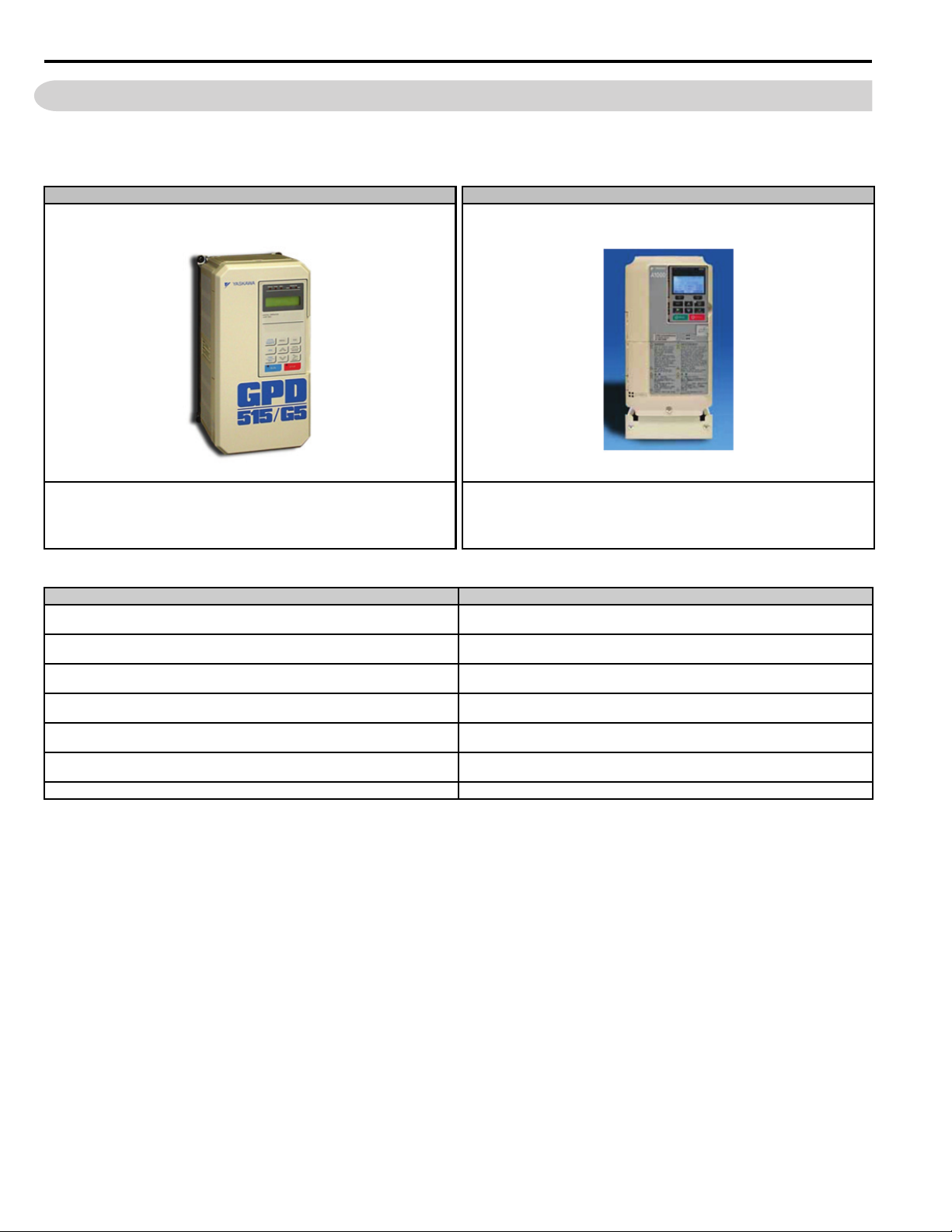
GPD515/G5 Drive A1000 Drive
The GPD515/G5 drive is primarily used for general purpose industrial applications.
The A1000 drive is primarily used for general purpose and high performance industrial
applications, including those that require precise torque and speed control as well as control
of both induction and permanent magnet motors.
Table 1 Key A1000 Features and Functions
Key A1000 Features and Functions Key A1000 Features and Functions
• Closed or open loop vector control for outstanding regulation, torque production, and
position control capability
• Continuous Auto-tuning optimizes performance by compensating for changes in motor
temperature
• High Frequency Injection enables high precision open loop control of Interior Permanent
Magnet Motors
• Fast acting current and voltage limiters help achieve continuous drive operation during
periods of excessive demand
• High Slip Braking reduces installation cost and the need for dynamic braking resistors
• Communication options for all major industrial networks provides high speed control and
monitoring, reducing installation cost
• DriveWizard computer software and Application Sets for easy configuration • Integrated DC Reactor (standard on 30 HP and larger) for input harmonic reduction
• Auxiliary Control Power Unit maximizes production time and efficiency by maintaining
network communication while main power is removed
• Embedded Safe Torque Off minimizes downtime for applications requiring occasional
intervention (SIL CL2, PLd, Category 3)
• Embedded function blocks, programmable with DriveWorksEZ, provide additional
application flexibility and the opportunity to eliminate separate controllers
• USB Copy Unit and Keypad configuration storage provide speed and convenience for
duplicate configuration of multiple drives
• Removable terminal board with configuration storage provides convenience of
configuration backup
• Made with RoHS compliant materials
4 YAS KA WA PL.A1000.01 G5 to A1000 - Product Transition Guide
Page 5

2 GPD515/G5 to A1000 Feature Differences
2 GPD515/G5 to A1000 Feature Differences
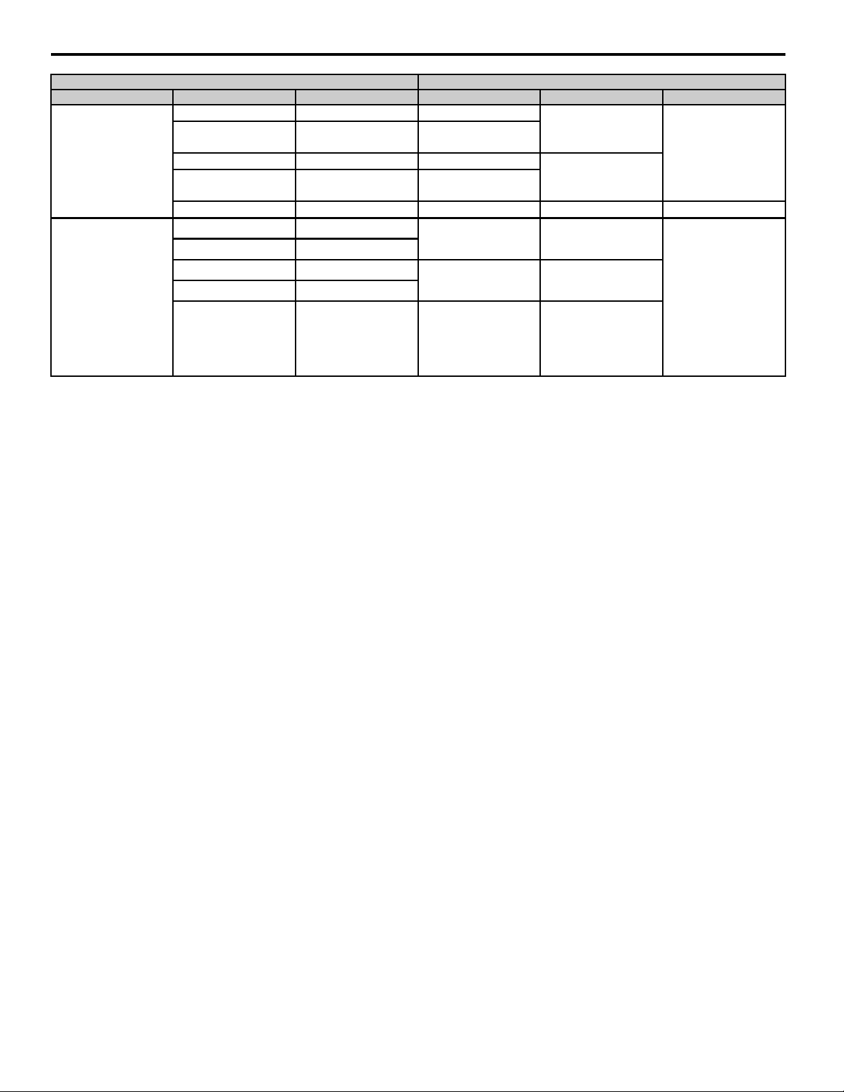
Table 2 Feature Differences
Feature Item Yaskawa GPD515/G5 Yaskawa A1000
200 V 240 V 0.5 to 150 HP
HP Range
Input Voltage Rated Voltage
Motor types — Induction Induction, Permanent Magnet
PWM Carrier Frequency Range See Appendix 1 See Appendix 1
Maximum Output Frequency Hz 400 Hz 400 Hz (1000 Hz optional)
Keypad Design
Digital Input Terminal NPN/PNP NPN Switchable NPN/PNP
Digital output Terminal
Analog Output Output Level
Pulse Input
Pulse Output
Quick Disconnect Terminals Type No Yes
Auto Tuning Methods Rotational Rotating, Stationary, Continuous, Inertia /ASR
Preset Speeds Qty. 8 17
Speed Search
Auto Restart Time Between Attemps 0.1 sec, fixed (Maximum 10 attempts) 0.0 – 5.0 sec (selectable)
Energy Savings Mode Man/Auto Manual/Auto Man/Auto
DC Injection Function At Start/At Stop At Start/At Stop At Start/At Stop +HSB during stop
Braking Function
Cooling Fan On/Off Control Power/Run No Selectable Always Active/During Run
Timer Function On/Off Delay On/Off Delay (0-300.0 sec) On/Off Delay (0-3000 sec)
Fault Code Additions — — 10 with elapsed time stamp
Torque Limit/Current Limit/
Stall Prevention
Harmonic Counter Measures
Ambient Temperature ºC
Storage Temperature ºC -20ºC ~ +60ºC -20ºC ~ +60ºC
Network Communications
Unique Feature/Function — — Over-excitation Braking
400 V 480 V 0.5 to 500 HP 480 V 0.75 to 900 HP (HD) 0.75 to 1000 HP (ND)
600 V 2 to 200 HP 600 V 2 to 250 HP (ND)
3-phase, 200-230 Vac
3-phase, 380-460 Vac
3-Phase, 500-600 Vac
Display 2 Line X 16 Character LCD 5 Line X 16 Character LCD keypad
Copy Function No Yes
Open Collector 2 0
Relay Output 1 x Form A, 1 x Form C 3 x Form A, 1 x Form C
2 channels
0-10 V or –10-+10 V or (9 bit plus sign)
Quantity: 0 1
Input Frequency N/A 1-32 kHz
Quantity: 0 1
Output Frequency N/A 1-32 kHz
Bi/Uni-Directional Uni-Directional Bi-Directional
Method Current Detection Current/Speed Estimation
DB Transistor
Special No High Slip/Over-excitation Braking
—
— Filters/Reactors (Options) Filters/Reactors (Options)
Built-In DC Bus Reactor
Standard
Optional
Built-in to 10 HP (240 V)
Built-in to 25 HP (480 V)
Built-in to 25 HP (575 V)
Stall Prevention
During Accel/Run/Decel (V/F)
Torque Limit in 4 Quadrants (Vector)
240 Vac: 25-100 HP (HD)
480 Vac: 30-500 HP (HD)
600 Vac: N/A
-10ºC ~ +40ºC (IP21)
-10ºC ~ +45ºC (IP00)
Modbus RTU
via RS232
RS232 to RS485, DeviceNet, ProfibusDP,
Interbus-S, Lonworks, ModbusPlus,
CanOpen, CC-link
<1> HD = Heavy Duty, ND = Normal Duty
240 V 0.75 to 150 HP (HD) 0.75 to 175 HP (ND) <1>
3-phase, 200-240 Vac
3-phase, 380-480 Vac
3-phase, 500-600 Vac
2 channels with independent level selections
0-10 V (10 bit plus sign) or
–10-+10 V or 10 bit plus sign or 4-20 ma 10 bit
Built-in to 40 HP (HD)
Stall Prevention
During Accel/Run/Decel (V/F)
Torque Limit in 4 Quadrants (Vector)
Software Current Limit (HD=150 %, ND=120 %)
240 Vac: 30-175 HP (ND)
480 Vac: 30-1000 HP (ND)
600 Vac: 30-250 HP (ND)
-10 to +50°C (Chassis Installation)
-10 to +40°C (Chassis with zero side clearance, or Type 1)
Modbus RTU
via terminal I/O RS485/422
DeviceNet, Profibus-DP, ProfiNet, Ethernet,
Modbus TCP/IP, Mechatrolink
YAS KA WA PL.A1000.01 G5 to A1000 - Product Transition Guide 5
Page 6
3 Digital Operator Comparison
&ƌĞƋƵĞŶĐLJZĞĨ
3 Digital Operator Comparison
• Enhanced LCD operator with built-in copy function and parameter verify for A1000
• Soft Keys simplify operation and programming
• Optional LED operator available for A1000
• LCD contrast adjustment
• Simplified parameter grouping for easier navigation and set-up
• The A1000 has a new layout for faster parameter selection
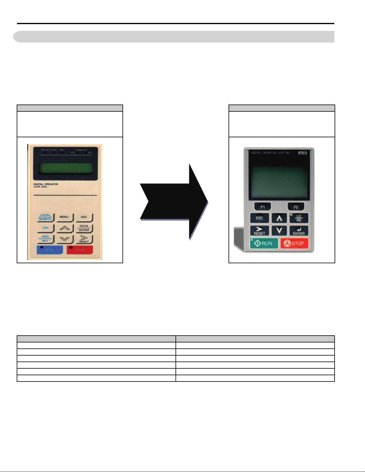
Table 3 Digital Operator
GDP515/G5 Operator New A1000 Operator
LCD Backlit Display
2 Line x 16 Characters
LCD Backlit Display
5 Line x 16 Characters
New Button Layout
Soft Keys (F1/F2)
Smaller
• A1000 copy keypad is capable of uploading all of the parameter settings from the A1000 drive memory.
• Upload of GPD515/G5 parameters to the A1000 is not available.
• A1000 drives must have the same software version, model, and control mode to copy parameters between A1000
drives.
• A Quick Start menu is added to aid in simple start up.
• The Quick Start menu consists of 26 parameters. The advanced menu offers full parameter access.
• There is a new button layout for quicker drive navigation.
Table 4 Menu Structure Comparison
GPD515/G5 A1000
Operation Operation
— Auto-Tuning
Programming (Quick Start, Basic, Advanced) Programming
Modified Constants Quick Settings
Auto-Tuning Modified Constants
Initialize Monitor Menu
6 YAS KA WA PL.A1000.01 G5 to A1000 - Product Transition Guide
Page 7
4 Front Cover & Cooling Fan Comparison
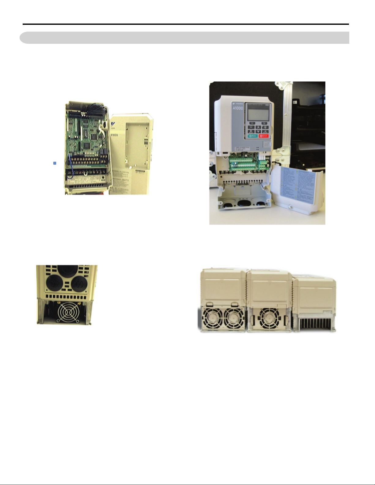
4 Front Cover & Cooling Fan Comparison
GPD515/G5 - Front Cover (not split) A1000 - Split Front Cover
The A1000 comes with a split cover to allow terminal only access. Limits exposure to control
PCB and power structure during wiring.
G5 Modular Cooling
• The A1000 features an easy to remove
top mounted heat sink fan.
• Fan operation is parameter controlled.
• Fan operation time can be monitored for
preventative maintenance.
A1000 - New Modular Top-Mounted Cooling Fan
YAS KA WA PL.A1000.01 G5 to A1000 - Product Transition Guide 7
Page 8
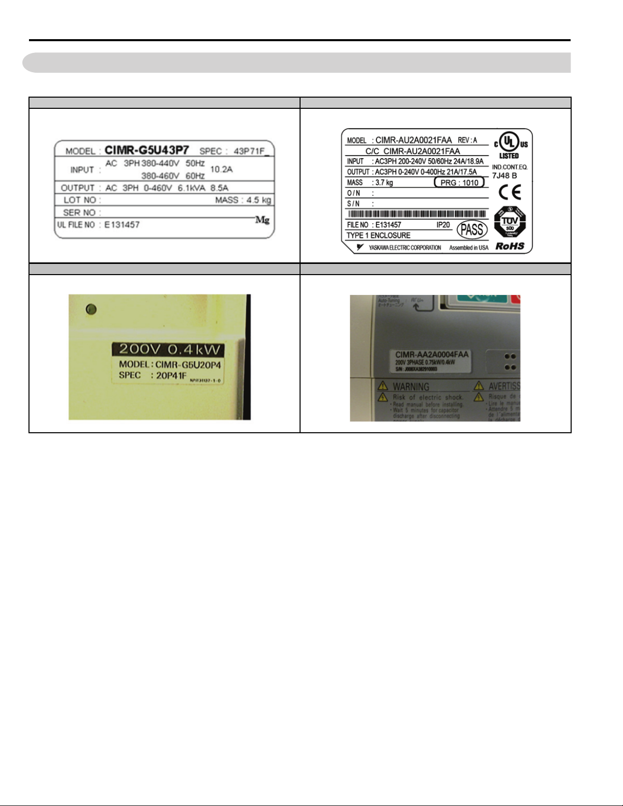
5 Nameplate/Labeling Differences
5 Nameplate/Labeling Differences
Table 5 Nameplates and Front Labels
GPD515/G5 Side Nameplate A1000 Side Nameplate
GPD515/G5 Front Label A1000 Front Label
8 YAS KA WA PL.A1000.01 G5 to A1000 - Product Transition Guide
Page 9
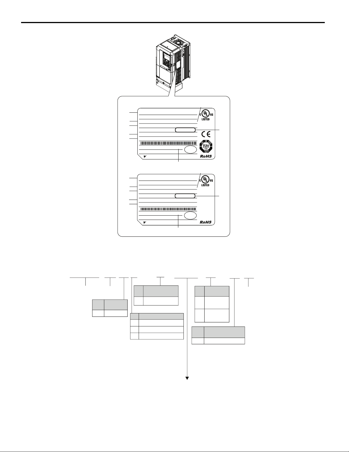
5 Nameplate/Labeling Differences
CIMR
-
A U 2 A
0021 F
AA
Drive
A1000
Series
No.
Enclosure
Type
Design
Revision
Order
No.
Customized
Specifications
A Standard model
IP00/Open
Type
F
IP20/NEMA
Type 1
A
No.
Environmental
Specification <1>
A Standard
Refer to Appendix 1, Amperage and Carrier Tables.
No.
Region
Code
USA
U
No. Voltage Class
3-phase, 380-480 Vac
3-phase, 200-240 Vac
2
4
3-phase, 500-600 Vac 5
H
G
F
E
D
B
C
A
PRG : 1010
IND.CONT.EQ.
7J48 B
YASKAWA ELECTRIC CORPORATION
Assembled in USA
:
CIMR-AU2A0021FAA
PASS
MODEL
INPUT
OUTPUT
MASS
O / N
S / N
FILE NO
TYPE 1 ENCLOSURE
REV : A
: AC3PH 200-240V 50/60Hz 24A/18.9A
: AC3PH 0-240V 0-400Hz 21A/17.5A
: 3.7 kg
:
:
: E131457 IP20
200/400 V Class
600 V Class
PRG : 504X
IND.CONT.EQ.
7J48 B
YASKAWA ELECTRIC CORPORATION
Assembled in USA
:
CIMR-AU5A0009FAA
: AC3PH 500-600V 50/60Hz 12.0A/8.3A
: AC3PH 0-600V 0-400Hz 9.0A/6.3A
: 3.7 kg
:
:
: E131457 IP20
PASS
MODEL
INPUT
OUTPUT
MASS
O / N
S / N
FILE NO
TYPE 1 ENCLOSURE
REV : A
H
G
F
E
D
A
B
C
C/C CIMR-AU2A0021FAA
C/C CIMR-AU5A0009FAA
A – Normal Duty Amps / Heavy Duty
Amps
B–
Software version
<1>
C – Enclosure type
D – Serial number
E – Lot number
F – Output specifications
G – Input specifications
H – AC drive model
YAS KA WA PL.A1000.01 G5 to A1000 - Product Transition Guide 9
Page 10
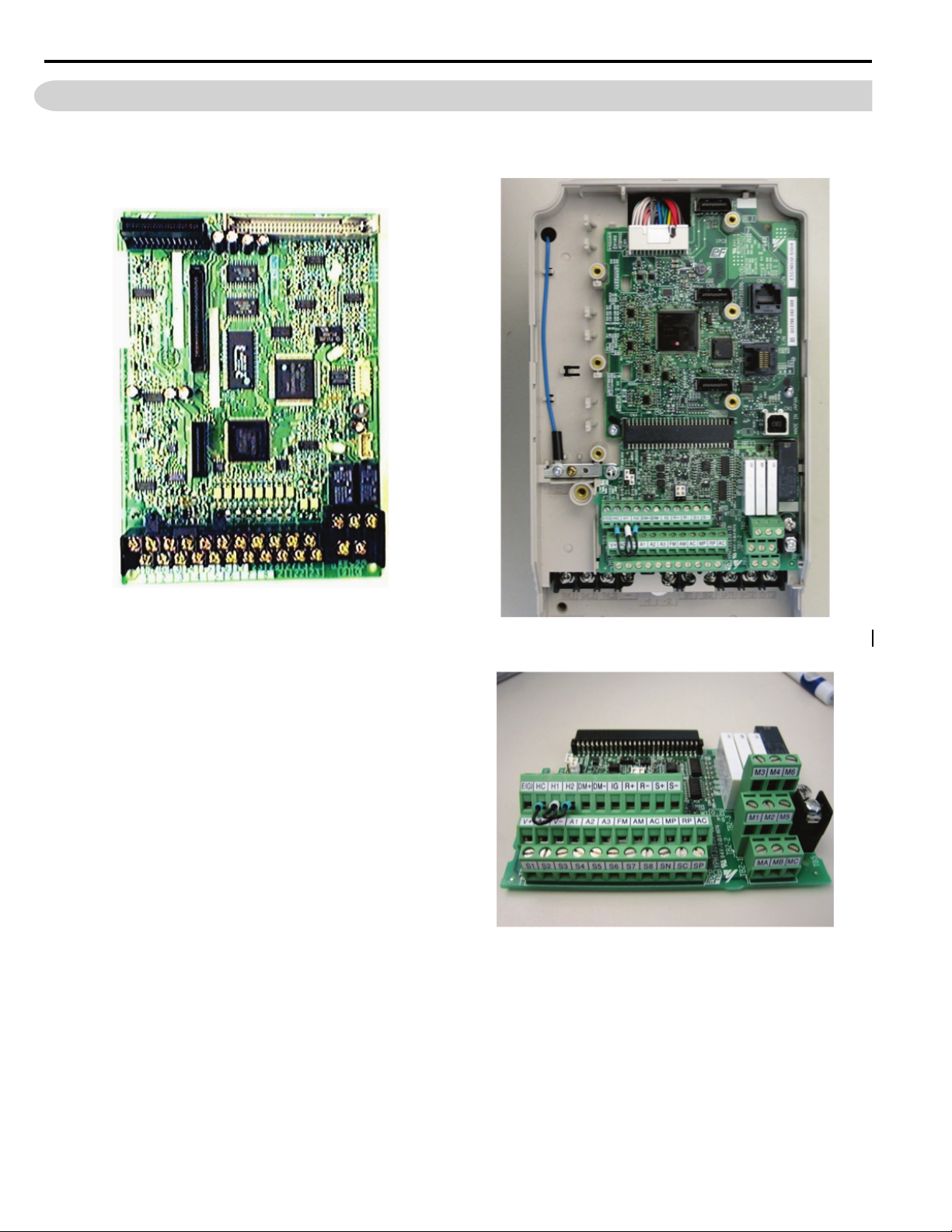
6 Main Control PCB Comparison
6 Main Control PCB Comparison
GPD515/G5 Control PCB New A1000 Control PCB
A1000 Removable Terminal Board
10 YAS KA WA PL.A1000.01 G5 to A1000 - Product Transition Guide
Page 11
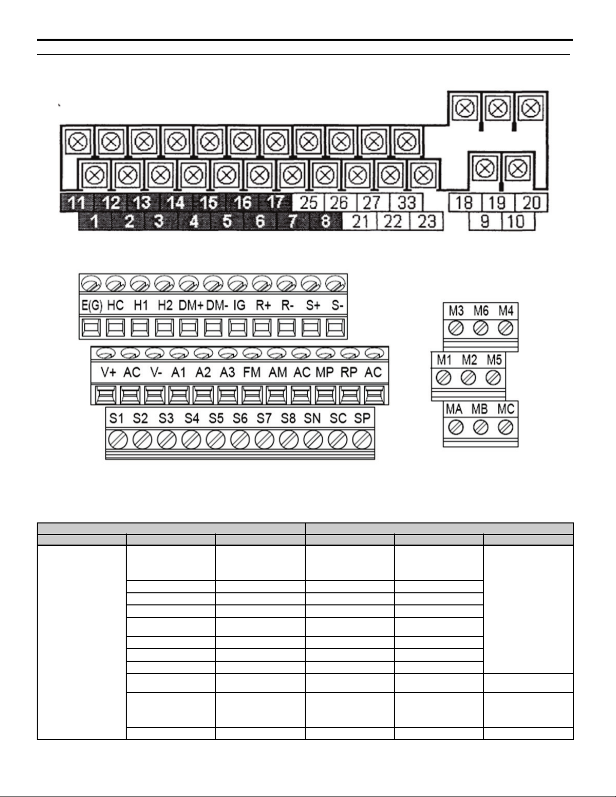
Terminal Board Set-Up Comparison
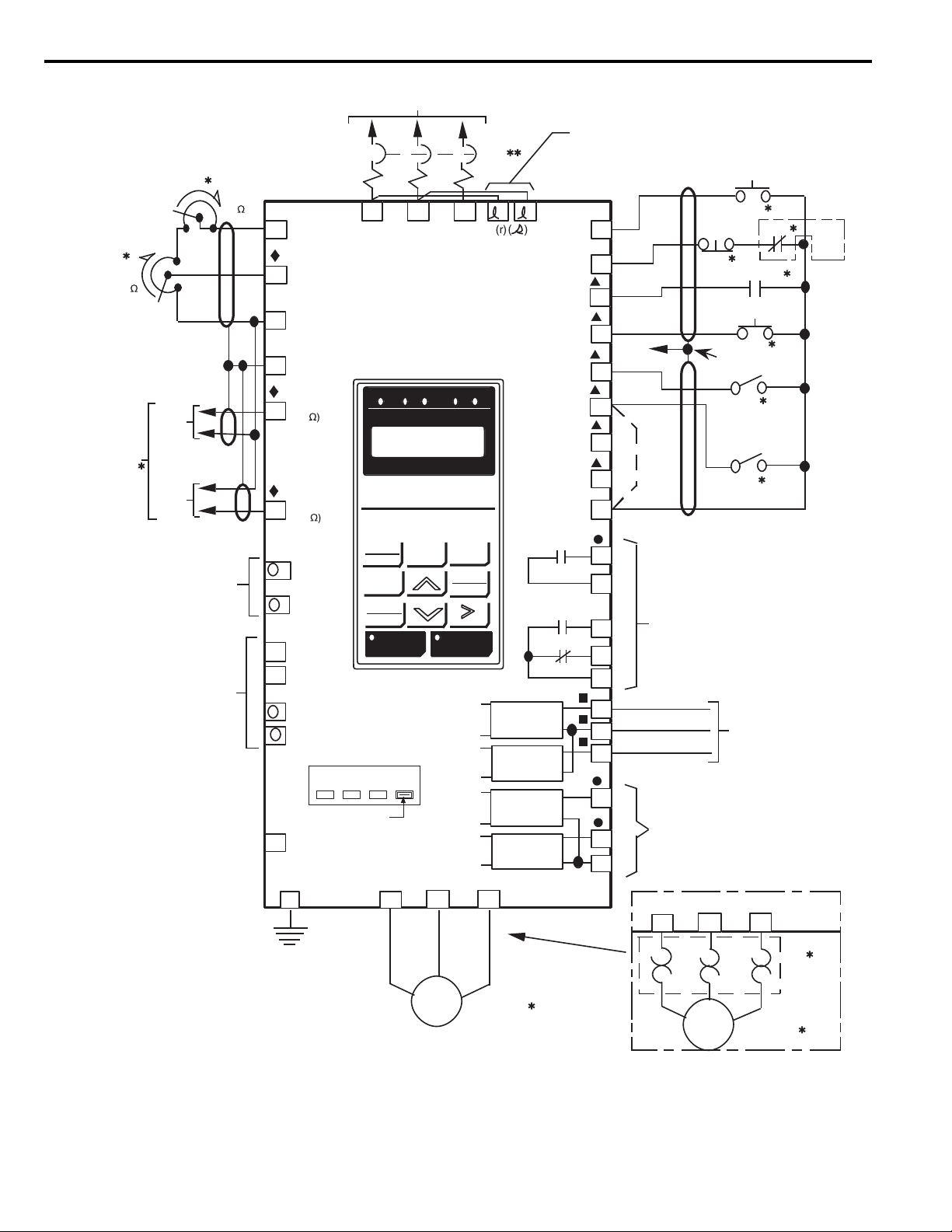
Figure 1
Figure 1 GPD515/G5 Terminal Board Configuration
Figure 2
6 Main Control PCB Comparison
Figure 2 A1000 Terminal Board Configuration
Table 6 Factory Default Functions 2-Wire Control
GPD515/G5 Terminal A1000 Terminal (Designations similar to GPD515/G5)
Typ e GPD515/G5 Terminal Default Functions A1000 Terminal Default Function A1000 Description
Forward run/stop
1
2 Reverse run/stop S2 Reverse run/stop command
3 External fault input S3 External fault input
4 Fault reset input S4 Fault reset
5
Digital Input Signals
6 Multi-step speed reference 2 S6 Multi-step speed reference 2
7 Jog reference S7 Jog frequency reference
8 External baseblock S8 External baseblock N.O.
11
— — SC Factory connected to SP
— — SP Factory connected to SC
YAS KA WA PL.A1000.01 G5 to A1000 - Product Transition Guide 11
Signal level:
(Photo-coupler insulated
Input: +24 Vdc, 8 mA)
Master/Auxilary change
Multi-step speed reference 1
Sequence control input
common
S1 Forward run/stop command
S5
SN Digital input common
Multi-step speed reference 1
(Master/auxiliary switch)
Multi-function inputs 1-8
Photocoupler
24 Vdc, 8 mA
Set the S3 jumper to select
between sinking, sourcing
mode, and the power supply.
Multi-function input
common
24 Vdc Power Supply for
Digital inputs, 150 mA max
(only when not using digital
input option DI-A3)
Page 12

6 Main Control PCB Comparison
GPD515/G5 Terminal A1000 Terminal (Designations similar to GPD515/G5)
Typ e GPD515/G5 Terminal Default Functions A1000 Terminal Default Function A1000 Description
15
33
13
Analog Input Signal
Digital Output Signals
Analog Output Signals
Pulse I/O
14
16
17
12
9
10 M2
25
27
26
27
18
19 MB
20 MC
21
23
22 Common (Current Monitor) AC Analog common –
— — RP Pulse input
— — MP Pulse monitor
+15 V Power supply output
for analog command
(Allowable current 20 mA
maximum)
-15V Power supply output
for analog command
(Allowable current 20mA
maximum)
Master frequency ref.
(voltage)
-10 to +10 V (20 k)
0 to +10V (20 k)
Master frequency ref.
(current)
4 to 20 mA (250 )
Multi-function analog input
-10 to +10 V (20 k),
0 to +10 V (20 k)
Common for control circuit
0 V
Connection to shield sheath
of signal lead
During running (NO contact)
Dry contact capacity:
250 Vac, 1 A or less 30 Vdc,
1 A or less
Zero speed detection
Open collector output
48 V, 50 mA or less
Open collector output
common
Speed agree detection
Open collector output
48 V, 50 mA or less
Open collector output
common
Fault contact output
(NO/NC contact)
When faulted : Closed
between terminals 18 and 20,
Open between terminals 19
and 20. Dry contact
capacity: 250 Vac 1 A or
less, 30 V 1 A or less
Frequency meter output
0 to 10 V, 2 mA or less
Current monitor
5 V = inverter rated current,
2 mA or less
+V +10.5 Vdc power output
-V -10.5Vdc power output
A1
A2
A3
AC
E(G)
M1
M3
M4
M5
M6
MA
FM
AM
Multi-function analog input
1 (Frequency reference bias)
Multi-function analog input
2 (Frequency reference bias)
Multi-function analog input
3 (Auxiliary frequency
reference), PTC input
Analog frequency reference
common
Shield wire, optional ground
line connection point
During run
(N.O. contact)
Zero speed
(N.O. contact)
Frequency agree
(N.O. contact)
Fault output signal
(SPDT)
Output frequency
(Multi-function)
Output current
(Multi-function)
+10.5 Vdc
(Maximum Current: 20mA)
-10.5Vdc (Maximum
Current: 20 mA)
-10 to 10 Vdc, 0 to 10 Vdc
(Input impedance: 20 k)
-10 to 10 Vdc, 0 to 10 Vdc
(Input impedance: 20 k)
4 to 20 mA, 0 to 20 mA
(Input impedance: 250 k)
(Voltage or current input
must be selected by DIP
switch S1 and H3-09)
-10 to 10 Vdc, 0 to 10 Vdc
(input impedance: 20 k)
Use DIP switch S4 on the
terminal board to select
between analog and PTC
input.
0 V
–
Form A dry contact capacity:
1 A maximum at 250 Vac
1 A maximum at 30 Vdc
Multi-function digital output.
Function set by H2-01.
Form A dry contact capacity:
1 A maximum at 250 Vac
1 A maximum at 30 Vdc
Multi-function digital output.
Function set by H2-02.
Form A Dry contacts
capacity:
1 A maximum at 250 Vac
1 A maximum at 30 Vdc
Multi-function digital output.
Function set by H2-03.
Form C dry contact capacity:
1 A maximum at 250 Vac
1 A maximum at 30 Vdc
0 to +10 Vdc or
+/-10 Vdc 500 ohm input
10 V=100 %
Output frequency
(Maximum current 2 mA).
4 to 20 mA
20 mA = 100 %
Output frequency,
Function set by H4-01.
0 to 32 kHz (3 k) ±5 %
High level voltages 3.5 to
13.2
Low level voltages 0.0 to 0.8
Duty Cycle (on/off) 30 % to
70 %, function set by H6-01.
0 to 32 kHz
+5 V output
(Load: 1.5 k)
Function set by H6-06.
12 YAS KAW A PL.A1000.01 G5 to A1000 - Product Transition Guide
Page 13
Typ e GPD515/G5 Terminal Default Functions A1000 Terminal Default Function A1000 Description
RS-485/422
Safe Diable Inputs
6 Main Control PCB Comparison
GPD515/G5 Terminal A1000 Terminal (Designations similar to GPD515/G5)
——R+
——R-
——S+
——S-
— — IG Signal common –
——
——
——
——
——HC
H1 Safe Disable Input 1
H2 Safe Disable Input 2
MEMOBUS/Modbus
Communication (RS485/
422)
Max 115.2 kBps
MEMOBUS/Modbus
Communication (RS485/
422)
Max 115.2 kBps
Safe Disable Function
Common
–
24 Vdc, 8 mA
One or both open: Output
disabled
Both closed: Normal
operation
Internal impedance: 3.3 k
Off time of at least 1 ms
Disconnect the wire jumpers
shorting terminals H1, H2,
and HC to use the Safe
Disable inputs. Set the S5
jumper to select between
sinking, sourcing mode, and
the power supply.
YAS KA WA PL.A1000.01 G5 to A1000 - Product Transition Guide 13
Page 14
6 Main Control PCB Comparison
380V
400/
415V 440V 460V
Voltage Selector
3ø POWER SUPPLY (SEE NAMEPLATE DATA)
1CB
GPD 515/G5
L1 L2 L3
15
16
17
12
14
13
+15Vdc
(20mA MAX)
MAN REF. IN
(0 TO ±10Vdc)
RUN
RUN
COM
SHIELD
4-20mA
(250
0 TO ±10Vdc
(20K
SEE
NOTE 4
4-20mA
0-10V
ISOLATED
AUTO
REFERENCE
SEE NOTE 6
1OL
SEE
NOTE
2
EXT. FAULT
EXT. FAULT RESET
3PB
SEE
NOTE 3
TO
TERM. 12
1R
2K
MAN SPEED
1RH
2K / 2.5K
SEE NOTE 1
FWD
REV
1SS
1PB
SEE
NOTE 1
1
2
3
4
5
6
7
8
11
9
STOP
EXT. FAULT
FAULT RESET
AUTO/MAN
MULTI-STEP
FREQ SELECT
JOG
SPEED
0 VOLTS
RUN CONTACT
RY1
10
FAULT CONTACTS
RY2
RY2
18
19
20
ANALOG
OUTPUT
OPEN
COLLECTOR
CIRCUIT
OPEN
COLLECTOR
CIRCUIT
21
22
25
26
27
RY CONTACTS
CAPACITY:
1A AT 250Vac
1A AT 30Vdc
MULTI-FUNCTION
MONITOR OUTPUT
0 to +10V or
–10 to +10V,
2mA MAX.
MULTIFUNCTION
OPEN
COLLECTOR
OUTPUTS
CAPACITY:
50mA AT 48Vdc MAX.
AC MOTOR
(T2)
(T1) (T3)
G
T1 T2 T3
(GPD515C-B041 thru -B096)
FACTORY SET FOR 460V
EARTH
GROUND
SEE NOTE 5
L1 L2 L3
BASIC INTERCONNECT DIAGRAM FOR 3-WIRE CONTROL
(R) (S) (T)
(E)
(U) (V) (W)
2PB
STOP
TERMINALS 1-8:
IF INPUT FROM RELAY CONTACTS:
RATED 30Vdc OR MORE,
100mA OR MORE
IF OPEN COLLECTOR INPUT:
RATED 35Vdc OR MORE,
100mA OR MORE
FOR WIRING
DYNAMIC
BRAKING
OPTION
SEE NOTE 7
12
COOLING
FAN
POWER
(GPD515C-A080 [CIMR-G5M20151F] AND ABOVE;
GPD515C-B041 [CIMR-G5M40151F] AND ABOVE;
GPD515C-C027 [CIMR-G5M50221F] AND ABOVE)
SEE NOTE 10
+ 1
+ 2
SEE NOTE 9
ANALOG
OUTPUT
23
FOR OPTIONAL
DC REACTOR
SEE NOTE 8
+
+
–
SEQ REF
DRIVE FWD REV REMOTE
DIGITAL OPERATOR
JVOP-130
DATA
ENTER
FWD
REV
RESET
RUN STOP
JOG
LOCAL
REMOTE
MENU ESC
FWD/REV
AUTO
MAN
2SS
1OL
SEE NOTE 2
T1 T2 T3
(U) (V) (W)
AC MOTOR
(T2)
(T1) (T3)
ALTERNATE
MOTOR CONNECTION
B1
B2
33
–15Vdc
(20mA MAX)
+ 3
–
OR
Figure 3
Figure 3 GPD515/G5 Connection Diagram
14 YAS KAW A PL.A1000.01 G5 to A1000 - Product Transition Guide
Page 15
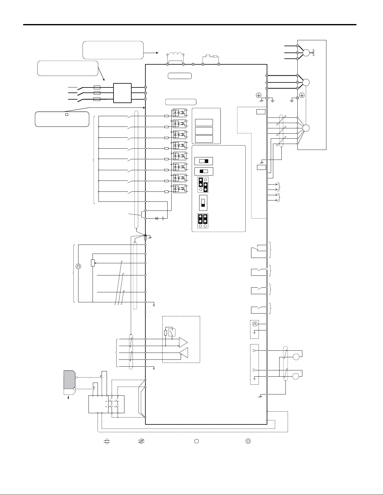
Figure 4
+
㧙
+
+
++
Terminals -, +1, +2, B1, B2 are
for connection options. Never
connect power supply lines to
these terminals
DC link choke
(option)
UX
Thermal relay
(option)
+
㧙
+
+
++
+
㧙
UX
S
1
S2
S3
S4
S5
S6
S7
MP
DM
DM
RP
A
1
A2
A3
0
V
AC
R
R
S
S
IG
H
1
H2
HC
Drive
B112
B2
2
k
S
8
SC
0 V
0 V
AC
FM
AM
AC
E (G)
S
1
S2
<1>
<2>
<3>
<11>
<7>
<12>
<13>
<8>
<10>
<7>
<5>
<4>
㧙
+
24 V
+
V
MA
M
1
M2
MB
MC
Jumper
Braking resistor
(option)
Forward Run / Stop
Reverse Run / Stop
External fault
Fault reset
Multi-speed step 1
Multi-speed step 2
External Baseblock
Jog speed
Multi-function
digtial inputs
(default setting)
Sink / Source mode
selection wire link
(default: Sink)
CN5-C
CN5-B
CN5-A
Option board
Pulse Train Input (max 32 kHz)
Shield ground terminal
Multi-function
analog/pulse
train inputs
Power supply +10.5 Vdc, max. 20 mA
Analog Input 1 (Frequency Reference Bias)
-10 to +10 Vdc (20 k )
Analog Input 2 (Frequency Reference Bias)
-10 to +10 Vdc (20 k )
0 or 4 to 20 mA (250 )
Analog Input 3 / PTC Input (Aux. frequency
reference)
-10 to +10 Vdc (20 k )
−
V
Power supply, -10.5 Vdc, max. 20 mA
Safety
switch
MEMOBUS/Modbus
comm. RS485/422
max. 115.2 kBps
Safe Disable inputs
Wire
jumper
Open
Safety relay /
controller
Termination resistor
(120 , 1/2 W)
DIP
Switch S2
Fault relay output
250 Vac, max. 1 A
30 Vdc, max 1 A
(min. 5 Vdc, 10 mA)
Multi-function relay output (During Run)
250 Vac, max. 1 A
30 Vdc, max 1 A
(min. 5 Vdc, 10 mA)
Multi-function pulse train output
(Output frequency)
0 to 32 kHz (2.2 k )
Multi-function analog output 1
(Output frequency)
-10 to +10 Vdc (2mA)
or 4 to 20 mA
EDM (Safety Electronic Device Monitor)
Main Circuit
Control Circuit
shielded line
twisted-pair shielded line
main circuit terminal
control circuit terminal
R/L1
S/L2
T/L3
R
S
T
Main
Switch
Fuse
EMC
Filter
M3
M4
Multi-function relay output (Zero Speed)
250 Vac, max. 1 A
30 Vdc, max 1 A
(min. 5 Vdc, 10 mA)
M5
M6
Multi-function relay output (Speed Agree 1)
250 Vac, max. 1 A
30 Vdc, max 1 A
(min. 5 Vdc, 10 mA)
SP
SN
<9>
AMFM
V
I
V
I
DIP Switch S1
A2 Volt/Curr. Sel
DIP Switch S4
A3 Analog/PTC
Input Sel
PTC
AI
Off
On
DIP Switch S2
Term. Res. On/Off
Jumper S3
H1, H2
Sink/Source Sel.
Jumper S5
AM/FM Volt./Curr.
Selection
Terminal board
jumpers and switches
FM
+
㧙
AM
<6>
<14>
Ω
Ω
Ω
Ω
Ω
Ω
<13>
Multi-function analog output 2
(Output current)
-10 to +10 Vdc (2mA)
or 4 to 20 mA
Three-Phase
Power Supply
200 to 600 V
50/60 Hz
<15>
<6>
A+
A
B
Z
B+
Z+
a+
ab+
bz+
z-
FE
IP
IG
TB1
SD
TB2
B track monitor
A track monitor
M
U/T
1
V/T2
W/T
U
FU
FV
FW
V
W
3
Ground
Cooling fan
PG
M
PGX3
connectors
(option)
Wiring sequence should shut off
power to the drive when a fault
output is triggered.
(Depending on
model capacity)
Ω
Models CIMR-A 4A930 and
4A1200 are compatible with
12-Phase Rectification.
6 Main Control PCB Comparison
YAS KA WA PL.A1000.01 G5 to A1000 - Product Transition Guide 15
Figure 4 A1000 Connection Diagram
Page 16

7 A1000 Drive Options
7 A1000 Drive Options
Category Option Name Model Number
Network Communication Profibus-DP SI-P3
DeviceNet SI-N3
Mechatrolink SI-T3
EtherNet/IP SI-EN3
Modbus TCP/IP SI-EM3
ProfiNET SI-EP3
Line Driver PG PG-X3
Motor Feedback
Input/Output
Keypad
Control Power Unit 24 V Control Power Unit
Parameter Management
DriveWorksEZ
Open Collector PG PG-B3
Serial Absolute FB FG-F3
Resolver Feedback PG-RT3
Analog Input AI-A3
Analog Output AO-A3
Digital Input DI-A3
Digital Output DO-A3
120 Vac Interface Board (Contact factory)
LCD Keypad JVOP-180
LED Keypad JVOP-182
Remote Mount Keypad Kit - Blank UUX000526
Remote Mount Keypad Kit - YEA UUX000527
LCD Operator Extension Cable, 1 m UWR0051
LCD Operator Extension Cable, 3 m UWR0052
Y-Stick USB Copy Unit JVOP-181
Drive Wizard Pro PC Support Tool DriveWizard Industrial
PC Support Tool Cable UWR0638 USB Cable, 10 ft, male A-type to male B-type
DriveWorksEZ Std (Contact factory)
DriveWorksEZ Pro (Contact factory)
PS-A10H for 480 V and 600 V class
PS-A10L for 240 V class
16 YAS KA WA PL.A1000.01 G5 to A1000 - Product Transition Guide
Page 17
8 Details on New A1000 Features and Functions
8 Details on New A1000 Features and Functions
Note: This section details significant A1000 features.
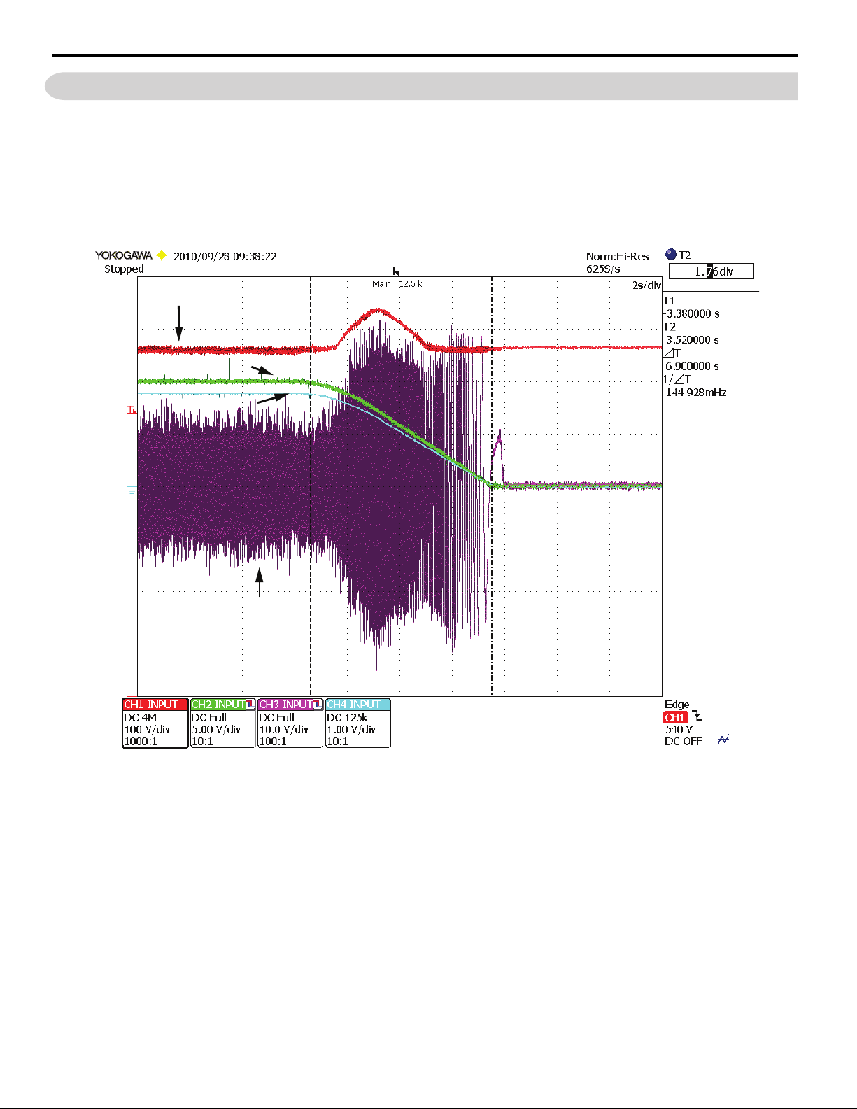
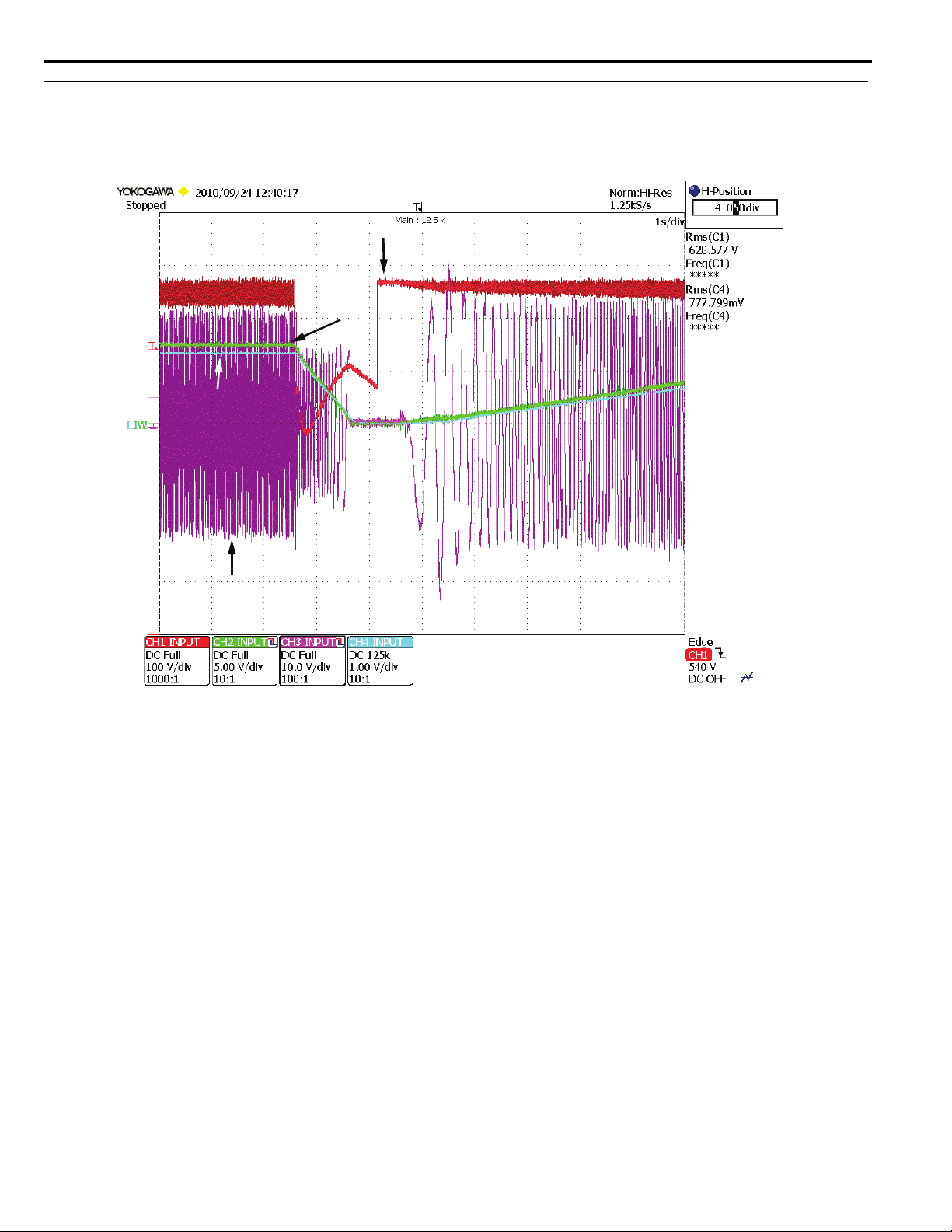
Over-Excitation Braking
This braking method allows for faster stops without the addition of a dynamic braking resistor. While still not as fast or powerful as
DB, it offers a very necessary middle ground for those applications that may not require the full power of dynamic braking, saving
money in hardware.
Figure 5
DC Bus V
Output Frequency
Motor Speed
Output Current
Figure 5 Over-Excitation Braking
YAS KA WA PL.A1000.01 G5 to A1000 - Product Transition Guide 17
Page 18
8 Details on New A1000 Features and Functions
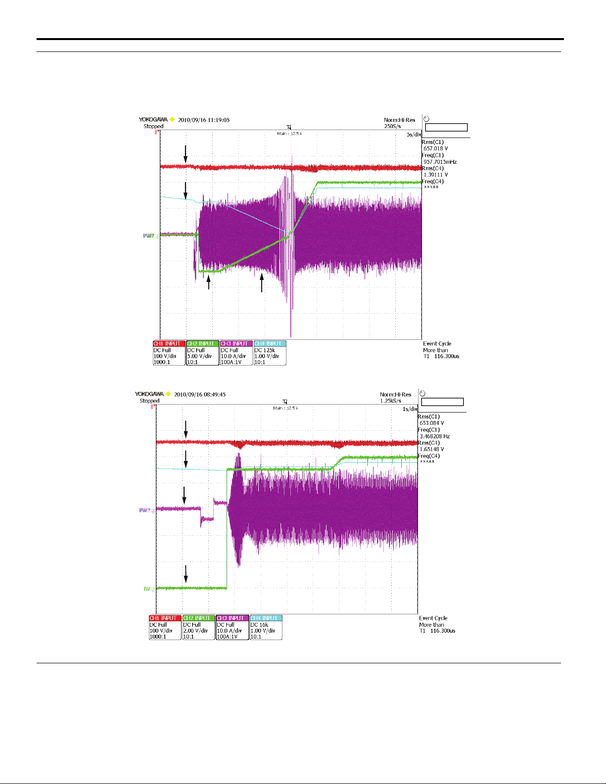
Self-Activated KEB
Internally activated Kinetic Energy Braking eliminates the need for external voltage sensing relays. Load inertia is used to decelerate
the system in a controlled manner in the event of power loss. Extremely fast scan rates accommodate loads near 100 %.
Figure 6
DC Bus V
Output Frequency
Motor Speed
Output Current
Figure 6 Self-Activated KEB
18 YAS KAW A PL.A1000.01 G5 to A1000 - Product Transition Guide
Page 19
8 Details on New A1000 Features and Functions
Bidirectional Speed Search
Multiple speed search methods to accommodate nearly any application. Bumpless synchronization with reverse motor rotation is
easily accomplished with Speed Estimation Speed Search.
Figure 7
DC Bus V
Motor Speed
Output Frequency
DC Bus V
Motor Speed
Output Current
Output Frequency
Output Current
SPEED SEARCH 45 Hz
SPEED SEARCH 60 Hz
Figure 7 Bi-Directional Speed Search
Top Mounted Easily Removable Cooling Fan
The heatsink fan is located on the top of the drive which improves the ease of replacement. With a tooless removal process, faulty
fans are easily replaced.
YAS KA WA PL.A1000.01 G5 to A1000 - Product Transition Guide 19
Page 20

8 Details on New A1000 Features and Functions
New “Heavy Duty” and “Normal Duty” Ratings for the A1000
The drive’s capacity is rated for two types of load characteristics, Heavy Duty (HD) and Normal Duty (ND). The table
below explains the drive characteristics for HD and ND ratings. Parameter C6-01 affects the drives carrier frequency
setting, and in certain models, the value of 100 % output current rating is also affected.
Table 7 Drive Selections
C6-01 Setting Carrier Frequency Output Current Ratings Overload Capacity Maximum Output Frequency
0: Heavy Duty
1: Normal Duty
(A1000 default)
Product C6-01 Heavy/Normal Duty Setting
New A1000
GPD515/G5
2 kHz (default)
Can be increased w/o derate
(Refer to Appendix 1)
2 kHz (default)
Can be increased with derate
(Refer to Appendix 1)
Table 8 C6-01 Heavy/Normal Duty Setting
C6-01 Drive Duty Selection Setting
0: Heavy Duty
• Rated output current is the HD (Heavy Duty) rating on drive nameplate.
• Overload capacity is 150 % for 1 minute.
• Carrier frequency is defaulted to 2 kHz but can be increased to 8 kHz or 5 kHz w/o derating on certain models (Refer to Appendix 1)
• Carrier frequency is automatically reduced when:
• output frequency is < 6.0 Hz and current is >100 %
• output frequency is > 6.0 Hz and current is > 112 %
• Maximum output frequency is 400 Hz (except on larger models)
• L8-15: OL2 Characteristic selection@low speed (=1 Enabled) expedites OL2 at low output frequencies below 6 Hz.
1: Normal Duty (default)
• Output current is ND (Normal Duty) rating on drive nameplate.
• Overload capacity is 120 % for 1 minute.
• Carrier frequency is defaulted to Swing PWM (2kHz) but can be increased with derating on most models (Refer to Appendix 1)
• Carrier is automatically reduced when:
• output frequency is < 6.0 Hz and current is >100 %
• output frequency is > 6.0 Hz and current is > 112 %
• Maximum output frequency is 400 Hz (except on certain larger models)
• L8-15: OL2 Characteristic selection@low speed (=1 Enabled) expedites OL2 at low output frequencies below 6 Hz.
Similar to Normal Duty, but with 150 % OL
• Singular output current value on nameplate.
• Overload capacity is 150 % for 1 minute.
• Full range carrier adjustment C6-02.
• Drive must be derated when carrier is set above default, software protected by OL2.
• Maximum output frequency is 400 Hz.
• L8-15: Characteristic selection @ low speed (=1 Enabled) expedites OL2.
HD nameplate rating 150 % 400 Hz
ND nameplate rating
ND rating is > HD rating
(On certain models, see ratings table)
120 % 400 Hz
20 YAS KAW A PL.A1000.01 G5 to A1000 - Product Transition Guide
Page 21
9 Appendix 1 Ratings
9 Appendix 1 Ratings
Output Amps, Carrier and Overload Comparison
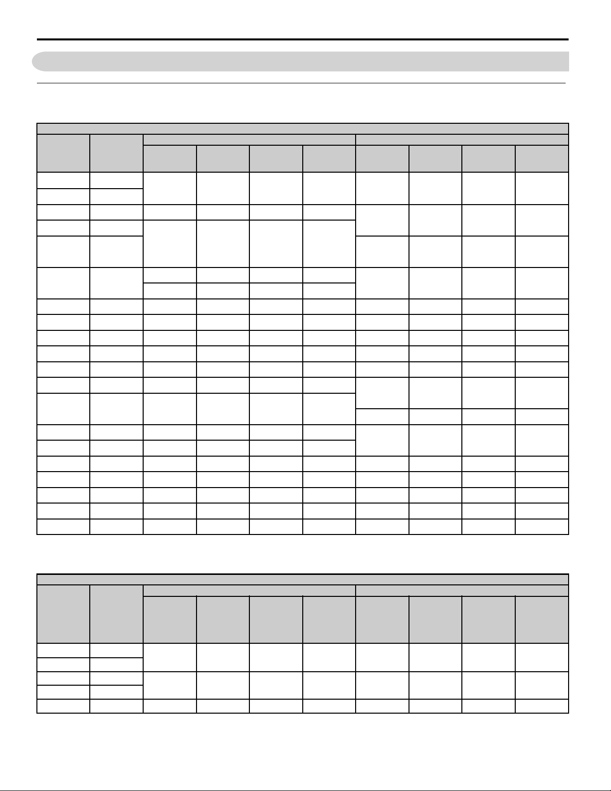
Table 9 240 V Heavy Duty Ratings
240 V Heavy Duty
A1000 (C6-01 = 0) GPD515/G5 Model
NEC HP 230 V NEC Amps
0.5 2.2
0.75 3.2
1 4.2 0006 5 2 (8) 150
1.5 6
26.8 21P51 8 15 150
A1000
Model
CIMR-AU2A
0004 3.2 2 (8) 150 20P41 3.2 15 150
0008
0010
Output Amps
Heavy Duty
6.9
8
Fc kHz Heavy
Duty <1>
2 (8) 150
Overload %
Heavy Duty
G5 Model
CIMR-G5U
20P71 6 15 150
Output Amps
Heavy Duty
Fc kHz
Heavy Duty
OL %
Heavy Duty
39.6
5 15.2 0021 17.5 2 (8) 150 23P71 17.5 15 150
7.5 22 0030 25 2 (8) 150 25P51 25 15 150
10 28 0040 33 2 (8) 150 27P51 33 15 150
15 42 0056 47 2 (8) 150 20111 49 15 150
20 54 0069 60 2 (8) 150 20151 64 15 150
25 68 0081 75 2 (8) 150
30 80 0110 85 2 (8) 150
40 104 0138 115 2 (5) 150
50 130 0169 145 2 (5) 150
60 154 0211 180 2 (5) 150 20370 160 10 150
75 192 0250 215 2 (5) 150 20550 224 10 150
100 248 0312 283 2 (5) 150 20750 300 10 150
125 312 0360 346 2 (5) 150 N/A N/A N/A N/A
150 360 0415 415 2 (5) 150 N/A N/A N/A N/A
0012 11 2 (8) 150
0018 14 2 (8) 150
22P21 11 15 150
20181 80 15 150
20221 96 10 150
20300 130 10 150
<1> Carrier setting in parenthesis indicates maximum value without derating (applies to HD rating only).
Table 10 240 V Normal Duty Ratings
240 V Normal Duty
A1000 (C6-01 = 1) GPD515/G5
NEC HP 230 V NEC Amps
0.5 2.2
0.75 3.2
14.2
1.5 6
2 6.8 0008 8 2 (SPWM) 120 21P51 8 15 150
A1000
Model
CIMR-AU2A
0004 3.5 2 (SPWM) 120 20P41 3.2 15 150
0006 6 2 (SPWM) 120 20P71 6 15 150
Output Amps
Normal Duty
Fc kHz
Normal Duty
Overload %
Normal Duty
GPD515/G5
Model
CIMR-G5U
Output Amps
Normal Duty
Fc kHz
Normal Duty
Overload %
Normal Duty
YAS KA WA PL.A1000.01 G5 to A1000 - Product Transition Guide 21
Page 22
9 Appendix 1 Ratings
240 V Normal Duty
A1000 (C6-01 = 1) GPD515/G5
NEC HP 230 V NEC Amps
39.6
5 15.2 0018 17.5 2 (SPWM) 120 23P71 17.5 15 150
7.5 22 0021 21 2 (SPWM) 120 25P51 25 15 150
10 28 0030 30 2 (SPWM) 120 27P51 33 15 150
15 42 0040 40 2 (SPWM) 120 20111 49 15 150
20 54 0056 56 2 (SPWM) 120 20151 64 15 150
25 68 0069 69 2 (SPWM) 120
30 80 0081 81 2 (SPWM) 120
40 104 0110 110 2 (SPWM) 120
50 130 0138 138 2 (SPWM) 120
60 154 0169 169 2 (SPWM) 120 20370 160 10 150
75 192 0211 211 2 (SPWM) 120 20550 224 10 150
100 248 0250 250 2 (SPWM) 120 20750 300 10 150
125 312 0312 312 2 (SPWM) 120 N/A N/A N/A N/A
150 360 0360 360 2 (SPWM) 120 N/A N/A N/A N/A
175 360 0415 415 2 (SPWM) 120 N/A N/A N/A N/A
A1000
Model
CIMR-AU2A
0010
0012
Output Amps
Normal Duty
9.6
12
Fc kHz
Normal Duty
2 (SPWM) 120 22P21 11 15 150
Overload %
Normal Duty
GPD515/G5
Model
CIMR-G5U
20181 80 15 150
20221 96 10 150
20300 130 10 150
Output Amps
Normal Duty
Fc kHz
Normal Duty
Overload %
Normal Duty
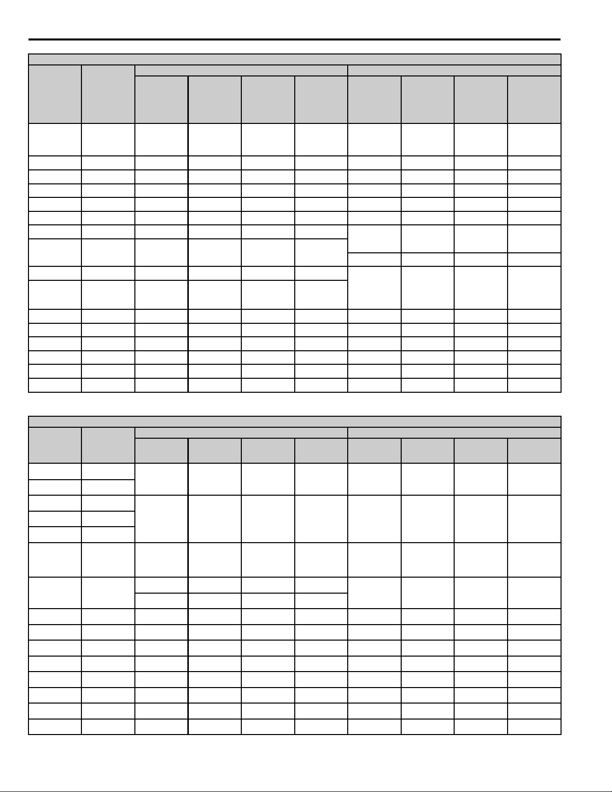
Table 11 480 V Heavy Duty Ratings
480 V Heavy Duty
A1000 (C6-01 = 0) GPD515/G5
NEC HP 460 V NEC Amps
0.5 1.1
0.75 1.6
12.1
23.4
34.8
57.6
7.5 11 0018 14.8 2 (8) 150 44P01 11 10 150
10 14 0023 18 2 (8) 150 45P51 14 10 150
15 21 0031 24 2 (8) 150 47P51 21 10 150
20 27 0038 31 2 (8) 150 40111 27 10 150
25 34 0044 39 2 (8) 150 40151 34 10 150
30 40 0058 45 2 (8) 150 40181 41 10 150
40 52 0072 60 2 (8) 150 40221 52 8 150
50 65 0088 75 2 (8) 150 40301 65 8 150
A1000
Model
CIMR-AU4A
0002 1.8 2 (8) 150 40P41 1.8 10 150
0004 3.4 2 (8) 150 40P71 3.4 10 1501.5 3
0005
0007
0009 7.2 2 (8) 150
0011 9.2 2 (8) 150
Output Amps
Heavy Duty
4.8
5.5
Fc kHz
Heavy
Duty <1>
2 (8) 150 41P51 4.8 10 150
Overload %
Heavy Duty
GPD515/G5
Model
CIMR-G5U
43P71 8 10 150
Output Amps
Heavy Duty
Fc kHz
Heavy Duty
Overload %
Heavy Duty
22 YAS KAW A PL.A1000.01 G5 to A1000 - Product Transition Guide
Page 23
9 Appendix 1 Ratings
480 V Heavy Duty
A1000 (C6-01 = 0) GPD515/G5
NEC HP 460 V NEC Amps
60 77 0103 91 2 (8) 150 40371 80 6 150
75 96 0139 112 2 (5) 150 40451 96 6 150
100 124 0165 150 2 (5) 150 40551 128 6 150
125 156
150 180
200 240 0296 260 2 (5) 150
250 302 0362 304 2 (5) 150
300 361 0414 370 2 (5) 150 41850 380 2 150
350 414 0515 450 2 (2) 150 42200 450 2 150
A1000
Model
CIMR-AU4A
0208
0250
Output Amps
Heavy Duty
180
216
Fc kHz
Heavy
Duty <1>
2 (5) 150
Overload %
Heavy Duty
GPD515/G5
Model
CIMR-G5U
40750 165 6 150
41100 224 5 150
41600 302 5 150
Output Amps
Heavy Duty
Fc kHz
Heavy Duty
Overload %
Heavy Duty
400 477
500 590
650 780 0930 810 2 (2) 150 N/A N/A N/A N/A
900 1080 1200 1090 2 (2) 150 N/A N/A N/A N/A
0675 605 2 (2) 150 43000 605 2 150
<1> Carrier setting in parenthesis indicates maximum without derating (applies to HD rating only).
Table 12 480 V Normal Duty Ratings
480 V Normal Duty
A1000 (C6-01=1) GPD515/G5
NEC HP 460 V NEC Amps
0.5 1.1
0.75 1.6
12.1
23.4
34.8
5 7.6 0009 8.8 2 (SPWM) 120 43P71 8 10 150
7.5 11 0011 11.1 2 (SPWM) 120 44P01 11 10 150
10 14 0018 17.5 2 (SPWM) 120 45P51 14 10 150
15 21 0023 23 2 (SPWM) 120 47P51 21 10 150
20 27 0031 31 2 (SPWM) 120 40111 27 10 150
25 34 0038 38 2 (SPWM) 120 40151 34 10 150
30 40 0044 44 2 (SPWM) 120 40181 41 10 150
40 52 0058 58 2 (SPWM) 120 40221 52 8 150
50 65 0072 72 2 (SPWM) 120 40301 65 8 150
60 77 0088 88 2 (SPWM) 120 40371 80 6 150
75 96 0103 103 2 (SPWM) 120 40451 96 6 150
100 124 0139 139 2 (SPWM) 120 40551 128 6 150
A1000
Model
CIMR-AU4A
0002 2.1 2 (SPWM) 120 40P41 1.8 10 150
0004 4.1 2 (SPWM) 120 40P71 3.4 10 1501.5 3
0005
0007
Output Amps
Normal Duty
5.4
6.9
Fc kHz
Normal Duty
2 (SPWM) 120 41P51 4.8 10 150
Overload %
Normal Duty
GPD515/G5
Model
CIMR-G5U
Output Amps
Normal
Duty
Fc kHz
Overload %
Normal
Duty
YAS KA WA PL.A1000.01 G5 to A1000 - Product Transition Guide 23
Page 24

9 Appendix 1 Ratings
480 V Normal Duty
A1000 (C6-01=1) GPD515/G5
NEC HP 460 V NEC Amps
125 156 0165 165 2 (SPWM) 120 40750 165 6 150
150 180 0208 208 2 (SPWM) 120 41100 224 5 150
200 240 0250 250 2 (SPWM) 120
250 302 0296 296 2 (SPWM) 120
300 361 0362 362 2 (SPWM) 120
350 414 0414 414 2 (SPWM) 120
400 477
500 590
600 — N/AN/AN/AN/A
800 — 0930 930 2 (SPWM) 120 N/A N/A N/A N/A
1000 — 1200 1200 2 (SPWM) 120 N/A N/A N/A N/A
A1000
Model
CIMR-AU4A
0515 515 2 (SPWM) 120
0675 675 2 (SPWM) 120
Output Amps
Normal Duty
Fc kHz
Normal Duty
Overload %
Normal Duty
Table 13 600 V Heavy Duty Ratings
600 V Heavy Duty Setting
A1000 (C6-01 = 0) GPD515/G5
NEC HP 575 V NEC Amps
1 1.7 0003 1.7 2 150
2 2.7 0004 3.5 2 150
3 3.9 0006 4.1 2 150 52P21 4.1 10 150
5 6.1 0009 6.3 2 150 53P71 6.3 10 150
7.5 9 0011 9.8 2 150 55P51 9.8 10 150
10 11 0017 12.5 2 150 57P51 12.5 10 150
15 17 0022 17 2 150 50111 17 10 150
20 22 0027 22 2 150 50151 22 10 150
25 27 0032 27 2 150 50181 27 10 150
30 32 0041 32 2 150 50221 32 10 150
40 41 0052 41 2 150 50301 41 10 150
50 52 0062 52 2 150 50371 52 10 150
60 62 0077 62 2 150 50451 62 10 150
75 77 0099 77 2 150 50551 77 10 150
100 99 0125 99 2 150 50751 99 2 150
125 125 0145 130 2 150 50900 130 2 150
150 144 0192 172 2 150 51100 172 2 150
200 192 0242 200 2 150 51600 200 2 150
A1000
Model
CIMR-AU5A
Output Amps Fc kHz
Overload %
Normal Duty
GPD515/G5
Model
CIMR-G5U
41600 302 5 150
41850 380 2 150
42200 450 2 150
43000 605 2 150450 515
GPD515/G5
Model
CIMR-G5U
51P51 3.5 10 150
Output Amps
Normal
Duty
Output Amps Fc kHz Overload %
Fc kHz
Overload %
Normal
Duty
24 YAS KAW A PL.A1000.01 G5 to A1000 - Product Transition Guide
Page 25

9 Appendix 1 Ratings
Table 14 600 V Normal Duty Ratings
600 V Norman Duty
A1000 (C6-01 = 0) GPD515/G5
NEC HP 600V NEC Amps
2 2.7 0003 2.7 <1>
3 3.9 0004 3.9 <1> 120 52P21 4.1 10 150
5 6.1 0006 6.1 <1> 120 53P71 6.3 10 150
7.5 9 0009 9 <1> 120 55P51 9.8 10 150
10 11 0011 11 <1> 120 57P51 12.5 10 150
15 17 0017 17 <1> 120 50111 17 10 150
20 22 0022 22 <1> 120 50151 22 10 150
25 27 0027 27 <1> 120 50181 27 10 150
30 32 0032 32 <1> 120 50221 32 10 150
40 41 0041 41 <1> 120 50301 41 10 150
50 52 0052 52 <1> 120 50371 52 10 150
60 62 0062 62 <1> 120 50451 62 10 150
75 77 0077 77 <1> 120 50551 77 10 150
100 99 0099 99 <1> 120 50751 99 2 150
125 125 0125 0125 <1> 120 50900 130 2 150
150 144 0145 0145 <1> 120 51100 172 2 150
200 192 0242 0242 <1> 120 51600 200 2 150
250 242 242 242 <1> 120————
A1000
Model
CIMR-AU5A
Output Amps Fc kHz
Overload %
Normal Duty
120 51P51 3.5 10 150
<1> The A1000’s default ND (normal duty) carrier frequency is a 2 kHz Swing PWM.
GPD515/G5
Model
CIMR-G5U
Output Amps Fc kHz Overload %
YAS KA WA PL.A1000.01 G5 to A1000 - Product Transition Guide 25
Page 26

9 Appendix 1 Ratings
Drive Derate Charts
Carrier Frequency Derate
240 Volt Class Drives
Figure 8
Figure 8 Carrier Frequency Derating (CIMR-A2A0004 to 2A0138)
Figure 9
480 Volt Class Drives
Figure 10
Figure11
Figure 9 Carrier Frequency Derating (CIMR-A2A0169 to 2A0415)
Figure 10 Carrier Frequency Derating (CIMR-A4A0002 to 4A0103)
Figure 11 Carrier Frequency Derating (CIMR-A4A0139 to 4A0362)
26 YAS KAW A PL.A1000.01 G5 to A1000 - Product Transition Guide
Page 27

Figure 12
Figure 13
9 Appendix 1 Ratings
Figure 12 Carrier Frequency Derating (CIMR-A4A0414)
Figure 14
600 Volt Class Drives
Figure 15
Figure 13 Carrier Frequency Derating (CIMR-A4A0515 to 4A0675)
Figure 14 Carrier Frequency Derating (CIMR-A4A0930 to 4A1200)
Figure 15 Carrier Frequency Derating (CIMR-A5A0003 to 5A0032)
YAS KA WA PL.A1000.01 G5 to A1000 - Product Transition Guide 27
Page 28

9 Appendix 1 Ratings
Figure 16
Figure 17
Figure 16 Carrier Frequency Derating (CIMR-A5A0041 to 5A0052)
Figure 18
Figure 17 Carrier Frequency Derating (CIMR-A5A0062 to 5A0077)
Figure 18 Carrier Frequency Derating (CIMR-A5A0099)
28 YAS KAW A PL.A1000.01 G5 to A1000 - Product Transition Guide
Page 29

9 Appendix 1 Ratings
Temperature Derating
Figure 19
Figure 19 Temperature Derating
Altitude Derating
The drive standard ratings are valid for installation altitudes up to 1000 m. For installations from 1000 m to 3000 m, the
drive rated output current must be derated for 1 % per 100 m above 1000 m.
Dimensions
Table 15 240 V Open-Chassis Models (IP00)
NOTE:
Unshaded A1000 cells show drives that are provided with standard NEMA Type 1/IP20 enclosures. Remove the conduit box and top cover plate to convert these
drives to Open-Chassis/IP00 enclosure type, then use the Open-Chassis dimensions provided in this table.
Outer Dimensions (in)
Voltage Class
GPD515/G5
Model
CIMR-G5U
A1000 Model
CIMR-
GPD515/G5 A1000
W H D W H D
3-Phase
240 V Class
20P41 2A0004
20P71
21P51
22P21
23P71 2A0021
25P51 2A0030
27P51 2A0040
20111 2A0056
20151 2A0069 15.75
20181
20221 26.57
20300
20370 2A0211
20550
20750
—
—
2A0006
2A0008
2A0010
2A0012
2A0081
2A0110 10 15.75 10.16
2A0138
2A0169
2A0250 18.7 31.5
2A0312 22.64 36.42 15.75
2A0360 — — —
2A0415 — — —
5.51 11.02
7.87 11.81 8.07 6.57
9.84
12.99
16.73 26.57
14.96
24.02
6.3
7.092A0018
8.86
11.22
13.78
5.79
5.51 10.24
6.46
7.09 11.81 7.36
8.66 13.78 7.76
10.98 17.72 10.16
12.95 21.65 11.14
17.95 27.76 12.99
19.84 31.5 13.78
YAS KA WA PL.A1000.01 G5 to A1000 - Product Transition Guide 29
Page 30

9 Appendix 1 Ratings
Table 16 480 V Open-Chassis Models IP00
NOTE:
Unshaded A1000 cells show drives that are provided with standard NEMA Type 1/IP20 enclosures. Remove the conduit box and top cover plate to convert these
drives to Open-Chassis/IP00 enclosure type, then use the Open-Chassis dimensions provided in this table.
Outer Dimensions (in)
Voltage Class
GPD515/G5
Model
CIMR-G5U
40P41 4A0002
A1000 Model
CIMR-AU
GPD515/G5 A1000
W H D W H D
3-Phase
480 V Class
6.3
40P71 4A0004
41P51
43P71
44P01 4A0018
47P51 4A0031
40111 4A0038
40151 4A0044 8.66 13.78 7.76
40181 4A0058
40221 4A0072 10.98 17.72
40301 4A0088
40371 4A0103
40451 4A0139 33.46
40551 4A0165
40750
41100
41600
41850
42200
4A0005
4A0007
4A0009
4A0011
4A0208 17.72 27.76 12.99
4A0250
4A0296
4A0362
4A0414
4A0515
5.51 11.02
7.09
7.87 11.81 8.07
9.84 14.96 8.86
24.02
12.99
17.91 32.28 13.78
22.64 36.42
37.4 57.09 17.13
30.91
11.22
14.76
15.75
5.51 10.24
7.09 11.81
10 15.75
20.08
12.95
21.65 11.14
19.69
31.5 13.78
37.4
5.79
6.46
6.5745P51 4A0023
7.36
10.16
14.57
This dimension
applies to all
larger models.
43000
—
—
0675 37.8 62.99 17.91
0930 — — —
1200 — — —
26.38 44.88
49.21 54.33
30 YAS KAW A PL.A1000.01 G5 to A1000 - Product Transition Guide
Page 31

Voltage Class
3-Phase 600 V
Class
9 Appendix 1 Ratings
Table 17 600 V Open Chassis/IP00
GPD515/G5
Model
CIMR-G5U
51P51
52P21 5A0006
53P71 5A0009
57P51 5A0017
50111 5A0022
50151 5A0027
50181 5A0032
50221 5A0041
50301 5A0052
50551 5A0099 41.34
50751 — 41.97 — — —
50900 — 49.21 12.99 — — —
51100 —
51600 — ———
A1000 Model
CIMR-AU
5A0003
5A0004
GPD515/G5 A1000
W H D W H D
5.51 11.02 7.08
7.87 11.81 8.0755P51 5A0011 6.57
9.84 14.96 8.85
15.75 29.53 11.22
33.47 11.8150371 5A0062
22.64
62.99 13.98
Outer Dimensions (in)
5.79
5.51 10.24
6.46
7.09 11.81 7.36
8.66 13.78 7.76
10.98 17.72 10.16
12.95 21.65 11.1450451 5A0077
12.8
———
Table 18 240 V NEMA Type 1/IP20
NOTE:
A1000 models noted with cell shading are provided as standard with Open/IP00 Protected Chassis. Order the appropriate NEMA Type 1/IP20 end cap kit when
NEMA Type 1/IP20 is required for these models.
Outer Dimensions (in)
6.30
5.51 11.81
7.092A0018
5.79
6.46
Voltage Class
3-Phase 240 V
Class
GPD515/G5
Model
CIMR-G5U
20P41 2A0004
20P71
21P51
22P21
23P71 2A0021
25P51 2A0030
27P51 2A0040
A1000 Model
CIMR-AU
2A0006
2A0008
2A0010
2A0012
GPD515/G5 A1000
W H D W H D
5.51 11.02
7.87 11.81 8.07 6.57
YAS KA WA PL.A1000.01 G5 to A1000 - Product Transition Guide 31
Page 32

9 Appendix 1 Ratings
NOTE:
A1000 models noted with cell shading are provided as standard with Open/IP00 Protected Chassis. Order the appropriate NEMA Type 1/IP20 end cap kit when
NEMA Type 1/IP20 is required for these models.
Outer Dimensions (in)
8.86
11.22
13.78
7.09 13.39 7.36
8.66 15.75 7.76
10.98 24.17
12.95 28.74 11.14
17.95 37.80 12.99
10.16
Voltage Class
3-Phase 240 V
Class
GPD515/G5
Model
CIMR-G5U
20111 2A0056
20151 2A0069 15.75
20181
20221 26.57
20300
20370 2A0211
20550
20750
A1000 Model
CIMR-AU
W H D W H D
9.84
2A0081
2A0110 10.00 21.02
2A0138
2A0169
2A0250 18.90 43.70
2A0312 22.83 50.79 15.75
12.99
16.83 38.78
GPD515/G5 A1000
14.96
24.02
N/A
2A0360 N/A N/A N/A 19.84 45.98 13.78
Table 19 480V NEMA Type1/IP20
NOTE:
A1000 models noted with cell shading are provided as standard with Open/IP00 Protected Chassis. Order the appropriate NEMA Type 1/IP20 end cap kit when
NEMA Type 1/IP20 is required for these models.
Outer Dimensions (in)
6.30
5.51 11.81
7.09 13.39
10 18.31
11.22
12.95
5.79
6.46
6.57
7.36
10.16
24.80
28.74 11.14
Voltage Class
3-Phase 480 V
Class
GPD515/G5
Model
CIMR-G5U
40P41 4A0002
40P71 4A0004
41P51
43P71
44P01 4A0018
45P51 4A0023
47P51 4A0031
40111 4A0038
40151 4A0044 8.66 15.75 7.76
40181 4A0058
40221 4A0072 10.98 20.28
40301 4A0088
40371 4A0103
40451 4A0139 33.46
40551 4A0165 32.28 13.78
A1000
Model
CIMR-AU
4A0005
4A0007
4A0009
4A0011
GPD15/G5 A1000
W H D W H D
5.51 11.02
7.87 11.81 8.07
9.84 14.96 8.86
24.02
12.99
30.91
32 YAS KAW A PL.A1000.01 G5 to A1000 - Product Transition Guide
Page 33

9 Appendix 1 Ratings
NOTE:
A1000 models noted with cell shading are provided as standard with Open/IP00 Protected Chassis. Order the appropriate NEMA Type 1/IP20 end cap kit when
NEMA Type 1/IP20 is required for these models.
Outer Dimensions (in)
17.95 37.80 12.99
19.84 45.98 13.78
— — —
Voltage Class
(continued)
3-Phase 480 V
Class
GPD515/G5
Model
CIMR-G5U
40750
41100 36.42 14.76
41600
41850
42200
A1000
Model
CIMR-AU
4A0208
4A0250
4A0296
4A0362
4A0414
4A0515
GPD15/G5 A1000
W H D W H D
32.28 13.78
17.91
22.64 36.42 15.75
37.40 57.09 17.13
43000
—
—
4A0675 37.80 62.99 17.91 — — —
4A0930 — — — — — —
4A1200 — — — — — —
Table 20 600V NEMA Type1/IP20
NOTE:
Models noted with cell shading are provided as standard with Open/IP00 Protected Chassis. Order the appropriate NEMA Type 1/IP20 end cap kit when
NEMA 1/IP20 is required for these models.
Outer Dimensions (in)
5.51 11.81
8.0755P51 5A0011 11.81 6.57
7.09 13.39 7.36
8.66 15.75 7.76
10.98 20.28 10.16
12.95 28.74 11.1450451 5A0077
12.8
17.95 37.80 12.99
19.84 45.98 13.78
Voltage Class
3-Phase 240 V
Class
GPD515/G5
Model
CIMR-G5U
51P51
52P21 5A0006
53P71 5A0009
57P51 5A0017 11.81
50111 5A0022
50151 5A0027
50181 5A0032
50221 5A0041
50301 5A0052
50551 5A0099 41.34
50751
50900
51100
51600
A1000 Model
CIMR-AU
W H D W H D
5A0003
5A0004
5A0125 41.97
5A0145 49.21 12.99
5A0192
5A0242
5.51 11.02 7.08
7.87
9.84 14.96 8.85
15.75 29.53 11.22
22.64
GPD515/G5 A1000
11.81
33.47 11.8150371 5A0062
62.99 13.98
5.79
6.46
YAS KA WA PL.A1000.01 G5 to A1000 - Product Transition Guide 33
Page 34

9 Appendix 1 Ratings
Braking Resistor Installation Attachment
The G5 allows a braking resistor to be installed directly to the unit on the backside (heatsink). The A1000 requires a
special attachment for installation. The table below lists the attachment sizes according to the drive capacity.
The attachment will increase the overall size of the drive when installing a braking resistor to certain A1000 models.
Figure 20
'
+
:
'
'
'
Figure 20 Installing a Braking Resistor on A1000 (240 V class 0.4 kW, or 0.5 HP)
Table 21 A1000 Dimensions after Installing Resistor Attachment
Dimensions (in)
Voltage
Class
3-Phase
200 V
Class
3-Phase
400 V
Class
3-Phase
600 V
Class
Capacity
(HP)
0.75
1 +0.59
2 +0.59
3
5 2.17 7.56 +0.48
0.75
1 +0.59
2 +0.59
3
5 +0.48
0.75
1 +0.59
2
3
5 +0.48
W H D1 D2 D W H D1 D2 D3 D
5.51 11.02 4.76
5.51 11.02 4.76
5.51 11.02 4.76
G5 A1000
1.54 6.30
5.51 10.23 4.29
2.32 7.08
1.54 6.30
5.51 10.23 4.29
2.32 7.08 2.17 7.56
1.54 6.30
5.51 10.23 4.29
2.32 7.08
1.5
1.5
1.5
2.17 7.56
1.10
1.10
1.10
6.89
6.89
6.89
D1, D2, D3
Differences
(in)
+0.59
+0.19
+0.59
+0.19
+0.59
+0.59
+0.19
Note: Use of the braking resistor attachment may void certain vibration and shock requirements, particularly when installed in
combination with other attachments for retrofitting A1000 to the GPD515/G5 installation. For areas where vibration is a major
concern, install the braking resistor directly to a seperate panel board instead of using the resistor attachment.
Attachment for
Braking Resistor
Model
(Parts Code)
EZZ020805A
(100-048-123)
Contact Factory
34 YAS KAW A PL.A1000.01 G5 to A1000 - Product Transition Guide
Page 35

9 Appendix 1 Ratings
Table 22 Heat Loss Data
Heat Loss Data (A1000 and GPD515/G5)
A1000 heat loss
G5 Model
CIMR-G5U
20P4 2A0004 50 15 65 44 14.8 58.8 88.00% 98.67% 90.46%
20P7 2A0006 65 25 90 48 24 72 73.85% 96.00% 80.00%
21P5
22P2
23P7 2A0021 80 135 215 67 101 168 83.75% 74.81% 78.14%
25P5 2A0030 90 210 300 92 194 286 102.22% 92.38% 95.33%
27P5 2A0040 110 235 345 105 214 319 95.45% 91.06% 92.46%
2011 2A0056 160 425 585 130 280 410 81.25% 65.88% 70.09%
2015 2A0069 200 525 725 163 395 558 81.50% 75.24% 76.97%
2018 2A0081 230 655 885 221 460 681 96.09% 70.23% 76.95%
2022 2A0110 280 830 1110 211 510 721 75.36% 61.45% 64.95%
2030
2037 2A0211 620 1110 1730 378 976 1354 60.97% 87.93% 78.27%
2055 2A0250 890 1740 2630 466 1514 1980 52.36% 87.01% 75.29%
2075 2A0312 1160 2050 3210 588 1936 2524 50.69% 94.44% 78.63%
40P4 4A0002 50 10 60 45 15.9 60.9 90.00% 159.00% 101.50%
40P7 4A0004 65 20 85 46 25 71 70.77% 125.00% 83.53%
41P5
43P7
44P0 4A0018 80 120 200 86 135 221 107.50% 112.50% 110.50%
45P5 4A0023 85 135 220 97 150 247 114.12% 111.11% 112.27%
47P5 4A0031 120 240 360 115 208 323 95.83% 86.67% 89.72%
4011 4A0038 150 305 455 141 263 404 94.00% 86.23% 88.79%
4015 4A0044 180 390 570 179 330 509 99.44% 84.62% 89.30%
4018 4A0058 195 465 660 170 349 519 87.18% 75.05% 78.64%
4022 4A0072 260 620 880 217 484 701 83.46% 78.06% 79.66%
4030 4A0088 315 705 1020 254 563 817 80.63% 79.86% 80.10%
4037 4A0103 370 875 1245 299 723 1022 80.81% 82.63% 82.09%
4045 4A0139 415 970 1385 416 908 1324 100.24% 93.61% 95.60%
4055 4A0165 710 1110 1820 580 1340 1920 81.69% 120.72% 105.49%
4075 4A0208 890 1430 2320 541 1771 2312 60.79% 123.85% 99.66%
4110 4A0250 1160 1870 3030 715 2360 3075 — — —
4160
4185 4A0414 1510 3400 4910 1164 3578 4742 77.09% 105.24% 96.58%
4220 4A0515 2110 4740 6850 1386 3972 5358 65.59% 83.80% 78.22%
4300 4A0675 2910 6820 9730 1685 4191 5876 57.90% 61.45% 60.39%
51P5
52P2 5A0006 60 45 105 43.7 28.1 71.8 72.83% 62.44% 68.38%
53P7 5A0009 75 65 140 68.9 43.4 112.3 91.87% 66.77% 80.21%
55P5 5A0011 105 100 205 88 56.1 144.1 83.81% 56.10% 70.29%
57P5 5A0017 90 130 220 146.7 96.6 243.3 163.00% 74.31% 110.59%
5011 5A0022 150 180 330 178.3 99.4 277.7 118.87% 55.22% 84.15%
5015 5A0027 210 250 460 227.2 132.1 359.3 108.19% 52.84% 78.11%
5018 5A0032 230 310 540 279.9 141.6 421.5 121.70% 45.68% 78.06%
5022 5A0041 340 380 720 — — 0 0.00% 0.00% 0.00%
5030 5A0052 390 430 820 — — 0 0.00% 0.00% 0.00%
A1000 Model
CIMR-AU
2A0008
2A0010
2A0012
2A0018
2A0138
2A0169
— 2A0360 — — — 783 2564 3347 — — —
— 2A0415 — — — 954 2564 3518 — — —
4A0005
4A0007
4A0009
4A0011
4A0296
4A0362
— 4A0930 — — — 2455 6912 9367 — — —
— 4A1200 — — — 3155 7626 10781 — — —
5A0003
5A0004
Internal External Total Internal External To tal Internal External
GPD515/G5 Watts A1000 Watts
80 40 120
60 80 140
440 930 1370
80 30 110
65 80 145
1520 2670 4190
55 35 90
49
52
58
60
250
306
49
53
55
61
787
985
23.3
33.6
35
43
64
77
662
816
37
48
53
69
2391
3075
21.5
27.5
84
95
122
137
912
1122
86
101
108
130
3178
4060
44.8
61.1
Comparison
(% of GPD515/G5)
61.25%
65.00%
96.67%
100.00%
56.82%
69.55%
61.25%
66.25%
84.62%
93.85%
51.78%
64.80%
42.36%
61.09%
87.50%
107.50%
80.00%
96.25%
71.18%
87.74%
123.33%
160.00%
66.25%
86.25%
89.55%
115.17%
61.43%
78.57%
Tot al
70.00%
79.17%
87.14%
97.86%
66.57%
87.90%
78.18%
91.82%
74.48%
89.66%
75.85%
96.89%
49.78%
67.89%
YAS KA WA PL.A1000.01 G5 to A1000 - Product Transition Guide 35
Page 36

9 Appendix 1 Ratings
Heat Loss Data (A1000 and GPD515/G5)
A1000 heat loss
G5 Model
CIMR-G5U
5037 5A0062 540 680 1220 — — 0 0.00% 0.00% 0.00%
5045 5A0077 750 900 1650 — — 0 0.00% 0.00% 0.00%
5055 5A0099 750 1000 1750 — — 0 0.00% 0.00% 0.00%
5075 5A0125 1150 1100 2250 — — 0 0.00% 0.00% 0.00%
5090 5A0145 1200 1150 2350 — — 0 0.00% 0.00% 0.00%
5110 5A0192 1800 1400 3200 — — 0 0.00% 0.00% 0.00%
5160 5A0242 1830 1870 3700 — — 0 0.00% 0.00% 0.00%
A1000 Model
CIMR-AU
Internal External Tota l Internal External To tal Internal External
GPD515/G5 Watts A1000 Watts
Comparison
(% of GPD515/G5)
Total
36 YAS KAW A PL.A1000.01 G5 to A1000 - Product Transition Guide
Page 37

Minimum Connectable Resistance
9 Appendix 1 Ratings
GPD515/G5 Drive Model CIMR-G5U
20P1 — 2A0004 48
20P2 — 2A0006 48
20P4 48 2A0008 48
20P7 48 2A0010 48
21P5 16 2A0012 16
22P2 16 2A0018 16
23P7 16 2A0021 16
25P5 9.6 2A0030 16
27P5 9.6 2A0040 9.6
2011 N/A 2A0056 9.6
2015 N/A 2A0069 9.6
2018 N/A 2A0081 9.6
40P2 2A0110 6.4
40P4 96 2A0138 6.4
40P7 96 4A0002 96
41P5 64 4A0004 96
42P2 64 4A0005 64
43P7 32 4A0007 64
44P0 32 4A0009 32
45P5 32 4A0011 32
47P5 32 4A0018 32
4011 20 4A0023 32
4015 20 4A0031 20
4018 N/A 4A0038 20
51P5 150 4A0044 19.2
52P5 150 4A0058 19.2
53P7 130 4A0072 19.2
55P5 90 5A0003 150
57P5 65 5A0004 150
5011 44 5A0006 150
5015 32 5A0009 130
5018 26 5A0011 90
5022 26 5A0017 65
— — 5A0022 44
— — 5A0027 32
— — 5A0032 26
Minimum Connectable Resistance
(Ω)
A1000 Drive Model CIMR-AU
Minimum Connectable Resistance
(Ω)
YAS KA WA PL.A1000.01 G5 to A1000 - Product Transition Guide 37
Page 38

10 Appendix 2 Parameter Cross Reference
10 Appendix 2 Parameter Cross Reference
Parameter Compatibility Table
This document lists the information needed to upgrade from G5 to a new A1000 drive. The A1000 drive must be set for Heavy Duty. First, set A1000
1.
parameter C6-01 to 0.
2. Check all G5 parameters that have been changed from their default settings by using the Modified Constants Menu.
3. Set the same control mode used for G5 to A1000.
4. Set parameters as described in this section.
Note: Default Values in the table below are listed for A1000 240 V Class 0.4 kW Drive Using Open Loop Vector Control.
Table 23 Parameter Cross Reference
Parameter Name
Environment Settings
G5 A1000 Comments (Gray shading indicates default settings)
No. Default No. Default G5 A1000
A1-00 A1-00
0: English 0: English
1: Japanese 1: Japanese
Language Selection for
digital operator display
Constant Access Level A1-01 2 A1-01 2
User setting constant A1-02 2 A1-02 2
Initialize A1-03 0 A1-03 0
Enter Password A1-04 0 A1-04 0000
Password 2 A1-05 0 A1-05 0000
User setting constant
A1-00 0 A1-00 0
A2-01 to
A2-32
A2-01 to
A2-32
2: German 2: German
3: French 3: French
4: Italian 4: Italian
5: Spanish 5: Spanish
6: Portuguese 6: Portuguese
— 7: Chinese
A1-01 A1-01
0: Monitor Custom
1: User Selection Parameter 1: User Parameters *
2: QUICK-START (Q)
4: ADVANCED (A)
* A2-01 through A2-32 Setting
A1-02 A1-02
0: V/f 0: V/f Control
1: V/f w/PG Control 1: V/f w/PG Control
2: Open Loop Vector 2: Open Loop Vector
3: Flux Loop Vector 3: Closed Loop Vector
5: Open Loop Vector for PM
A1-03 A1-03
0: No initialization 0: No initialization
1110: User Setting 1110: User initialize
2220: 2-wire sequence 2220: 2-wire sequence
3330: 3-wire sequence 3330: 3-wire sequence
5550: Reset OPE04
If setting A1-01 to 1, refer to the manual and set parameters A2-01
to A2-32.
0: Operation only
(monitors only)
2: All parameters 3: BASIC (B)
6: Advanced Open Loop Vector
Control for PM
7: Closed Loop Vector Control
for PM
38 YAS KA WA PL.A1000.01 G5 to A1000 - Product Transition Guide
Page 39

10 Appendix 2 Parameter Cross Reference
Parameter Name
Operation Mode
Selection
DC Injection Braking
Speed Search
Speed Search
Timers
G5 A1000 Comments (Gray shading indicates default settings)
No. Default No. Default G5 A1000
Reference Selection b1-01 1 b1-01 1
Operation Method
Selection
Stopping Method
Selection
Prohibition of Reverse
Operation
Operation Selection for
setting of E1-09 or
Less
Read sequence input
twice
Operation Selection
After Switching to
Remote Mode
Run Command
Selection in PRG
Mode
Run Command at
Power Up
Zero speed level (DC
injection braking
starting frequency)
DC Injection Braking
current
DC Injection Braking
Time at Start
DC Injection Braking
Time at Stop
Magnetic Flux
Compensation volume
Speed Search Selection
at start
Speed Search
Operating Current
Speed Search
Deceleration Time
Timer Function OnDelay Time
Timer Function OffDelay Time
b1-02 1 b1-02 1
b1-03 0 b1-03 0
b1-04 0 b1-04 0
b1-05 0 b1-05 0
b1-06 1 b1-06 1
b1-07 0 b1-07 0
b1-08 0 b1-08 0
b1-17 0
b2-01 0.5 Hz b2-01 0.5 Hz
b2-02 50 % b2-02 50 %
b2-03 0.00 s b2-03 0.00 s
b2-04 0.00 s b2-04 0.50 s* *Determined by the control mode selected.
b2-08 0 % b2-08 0 %
b3-01 0* b3-01 0*
b3-02 100 %* b3-02 120 %* *Default value changes according to the control mode.
b3-03 2.0 s b3-03 2.0 s
b4-01 0.0 s b4-01 0.0 s
b4-02 0.0 s b4-02 0.0 s
b1-01 b1-01
0: Operator 0: Operator
1: Control circuit terminal
(analog input)
2: Serial Communication 2: MEMOBUS comm.
3: Option PCB 3: Option PCB
4: EWS 4: Pulse train input
b1-02 b1-02
0: Operator 0: Operator
1: Control circuit terminal 1: Control circuit terminal
2: Serial Communication 2: MEMOBUS comm.
3: Option PCB 3: Option PCB
4: EWS Not available
b1-03 b1-03
0: Ramp to stop 0: Ramp to stop
1: Coast to stop 1: Coast to stop
2: DC Injection Braking 2: DC Injection Braking
3: Coast to stop with timer 3: Coast to stop with timer
b1-04 b1-04
0: Reverse possible 0: Reverse possible
1: Reverse prohibited 1: Reverse prohibited
b1-05 b1-05
0: Run at frequency reference 0: Run at frequency reference
1: Shut off drive output 1: Shut off drive output
2: Operate by E1-09 2: Operate by E1-09
3: Zero speed 3: Zero speed
b1-06 b1-06
0: 2 ms - 2 scans 0: 1 ms - 1 scan
1: 5 ms - 2 scans 1: 1 ms - 2 scans
b1-07 b1-07
0: Cycle Run command 0: Cycle Run command
1: Accept external Run cmd 1: Accept external Run cmd
b1-08 b1-08
0: Disabled. 0: Disabled.
1: Run cmd always accepted 1: Run cmd always accepted
2: Cannot enter Program Mode
0: Prohibited
1: Allowed
Change b1-17 to 1.
b3-01 b3-01
0: Disabled 0: Disabled
1: Enabled 1: Enabled
*Default value changes according to the control mode.
1: Control circuit terminal
(analog input)
YAS KA WA PL.A1000.01 G5 to A1000 - Product Transition Guide 39
Page 40

10 Appendix 2 Parameter Cross Reference
Parameter Name
PDI Control
Dwell Function
Droop Control
Energy Saving Control
G5 A1000 Comments (Gray shading indicates default settings)
No. Default No. Default G5 A1000
b5-01 b5-01
0: Disabled 0: Disabled
PID Control Method
Selection
Proportional Gain
Setting (P)
Integral Time Setting
(I)
Integral Limit Setting b5-04 100.0 % b5-04 100.0 %
Derivative Time (D) b5-05 0.00 s b5-05 0.00 s
PID Output Limit b5-06 100.0 % b5-06 100.0 %
PID Offset adjustment b5-07 0.0 % b5-07 0.0 %
PID Primary Delay
Time
PID Output
Characteristics
Selection
PID Output Gain
Setting
PID Output Reverse
Selection
Selection PID
Feedback Command
Loss Detection
PID Feedback
Command Loss
Detection Level
PID Feedback
Command Loss
Detection Time
Dwell Reference at
Start
Dwell Time at Start b6-02 0.0 s b6-02 0.0 s
Dwell Frequency at
Stop
Dwell Time at Stop b6-04 0.0 s b6-04 0.0 s
Droop Control Gain b7-01 0.0 % b7-01 0.0 %
Droop Control Delay
Time
Energy Saving Gain b8-01 80 %
Energy Saving
Frequency
b5-01 0 b5-01 0
b5-02 1.00 b5-02 1.00
b5-03 1.0 s b5-03 1.0 s
b5-08 0.00 s b5-08 0.00 s
b5-09 0 b5-09 0
b5-10 1.0 b5-10 1.00 Minimum setting units vary.
b5-11 0 b5-11 0
b5-12 0 b5-12 0
b5-13 0 % b5-13 0 %
b5-14 1.0 s b5-14 1.0 s
b6-01 0.0 Hz b6-01 0.0 Hz
b6-03 0.0 Hz b6-03 0.0 Hz
b7-02 0.05 s b7-02 0.05 s
b8-01 0
b8-02 0.7 1: Enabled
b8-02 0.0 Hz
1: D = control for bias 1: D control for bias
2: D control of feedback 2: D control of feedback
3: D control of Freq. Ref. + PID
output bias
4: D control of Freq. Ref. + PID
output
b5-09 b5-09
0: FWD 0: FWD
1: REV 1: REV
b5-11 b5-11
0: Negative PID output triggers
zero limit
1: Rotation direction reverses
with negative PID output.
b5-12 b5-12
0: No Detection 0: No Detection
1: Continue operation 1: Continue operation
2: Fault 2: Fault
b8-01 b8-01
Enabled via multi-function
input ( H1-XX=63)
This parameter is not available in A1000, and therefore does not
need to be set.
3: D control of Freq. Ref. + PID
output bias
4: D control of Freq. Ref. + PID
output
0: Negative PID output triggers
zero limit
1: Rotation direction reverses
with negative PID output.
3: Multi-function output only
detected during PID control
cancel input only.
4: An alarm is triggered and the
drive continues running.
Detected only when PID control
is canceled.
5: Fault is triggered and output
is shut off. Detected only when
PID control is canceled.
0: Disabled
Not available
in A1000
Divide the
setting of
b8-01 in G5
by 100
40 YAS KAW A PL.A1000.01 G5 to A1000 - Product Transition Guide
Page 41

10 Appendix 2 Parameter Cross Reference
Parameter Name
Zero Servo
Accel/Decel Time
S-Curve
Characteristics
Slip Compensation
Torque Compensation
Speed Control (ASR)
G5 A1000 Comments (Gray shading indicates default settings)
No. Default No. Default G5 A1000
Zero Servo Gain b9-01 5 b9-01 5
Zero Servo Completion
Width
Acceleration Time 1 C1-01 10.0 s C1-01 10.0 s
Deceleration Time 1 C1-02 10.0 s C1-02 10.0 s
Acceleration Time 2 C1-03 10.0 s C1-03 10.0 s
Deceleration Time 2 C1-04 10.0 s C1-04 10.0 s
Acceleration Time 3 C1-05 10.0 s C1-05 10.0 s
Deceleration Time 3 C1-06 10.0 s C1-06 10.0 s
Acceleration Time 4 C1-07 10.0 s C1-07 10.0 s
Deceleration Time 4 C1-08 10.0 s C1-08 10.0 s
Emergency Stop Time C1-09 10.0 s C1-09 10.0 s
Accel/Decel Time
Setting Unit
Accel/Decel Time
Switch Frequency
S-Curve Characteristic
at Accel Start
S-Curve Characteristic
at Accel End
S-Curve Characteristic
at Decel Start
S-Curve Characteristic
at Decel End
Slip Compensation
Gain
Slip Compensation
Primary Delay Time
Slip Compensation
Limit
Slip Compensation
Selection during
Regeneration
Flux calculation
method
Output Voltage
Limited Operation
Selection
Torque Compensation
Gain
Torque Compensation
Primary Delay Time
Torque Compensation
at Forward Start
Torque Compensation
at Reverse Start
Torque Compensation
Time Constant
ASR Proportional Gain
1
ASR Integral Time 1 C5-02 0.500 sec* C5-02 0.500 sec*
ASR Proportional Gain
2
ASR Integral Time 2 C5-04 0.500 sec* C5-04 0.500 s*
ASR Limit C5-05 5.0 % C5-05 5.0 %
ASR Primary Delay
Time Constant
Frequency
ASR Integral Limit C5-08 400 % C5-08 400 %
b9-02 10 b9-02 10
C1-10 C1-10
C1-10 1 C1-10 1
C1-11 0.0 Hz C1-11 0.0 Hz
C2-01 0.20 s C2-01 0.20 s
C2-02 0.20 s C2-02 0.20 s
C2-03 0.20 s C2-03 0.20 s
C2-04 0.00 s C2-04 0.00 s
C3-01 1.0* C3-01 1.0* *Determined by the control mode selected.
C3-02 200 ms* C3-02 200 ms* *Determined by the control mode selected.
C3-03 200 % C3-03 200 %
C3-04 0 C3-04 0
C3-05 0 - 0
C3-06 0 C3-05 0
C4-01 1.00 C4-01 1.00
C4-02 20 ms* C4-02 20 ms* *Determined by the control mode selected.
C4-03 0.0 % C4-03 0.0 %
C4-04 0.0 % C4-04 0.0 %
C4-05 10 ms C4-05 10 ms
C5-01 20.00* C5-01 20.00*
C5-03 20.00* C5-03 20.00*
C5-06 0.004 sec C5-06 0.004 sec
C5-07 0.0 Hz C5-07 0.0 Hz
0: 0.01 sec units 0: 0.01 sec units
1: 0.1 sec units 1: 0.1 sec units
C3-04 C3-04
0: Disabled 0: Disabled
1: Enabled 1: Enabled
This parameter is not available in A1000, and therefore does not
need to be set.
C3-06 C3-05
0: Disabled 0: Disabled
1: Enabled 1: Enabled
*Determined by the control mode selected. Default shown here is
for when using Closed Loop Vector Control.
* Default shown here is for when using Closed Loop Vector.ASR Gain Switching
YAS KA WA PL.A1000.01 G5 to A1000 - Product Transition Guide 41
Page 42

10 Appendix 2 Parameter Cross Reference
Parameter Name
Carrier Frequency
Hunting Prevention
Function
Factory Tuning
Parameters
Frequency Reference
Frequency Limits
Setting Prohibited
Frequency
Frequency Reference
Hold
Torque Control
G5 A1000 Comments (Gray shading indicates default settings)
No. Default No. Default G5 A1000
Carrier Frequency
Upper Limit
Carrier Frequency
Lower Limit
Carrier Frequency
Proportional Gain
Hunting prevention
function selection*
Hunting Prevention
Gain *
Carrier frequency
selection during
autotuning
Frequency Reference 1 d1-01 0.00 Hz d1-01 0.00 Hz
Frequency Reference 2 d1-02 0.00 Hz d1-02 0.00 Hz
Frequency Reference 3 d1-03 0.00 Hz d1-03 0.00 Hz
Frequency Reference 4 d1-04 0.00 Hz d1-04 0.00 Hz
Frequency Reference 5 d1-05 0.00 Hz d1-05 0.00 Hz
Frequency Reference 6 d1-06 0.00 Hz d1-06 0.00 Hz
Frequency Reference 7 d1-07 0.00 Hz d1-07 0.00 Hz
Frequency Reference 8 d1-08 0.00 Hz d1-08 0.00 Hz
Jog Frequency
Reference 9
Frequency Reference
Upper Limit Value
Frequency Reference
Lower Limit Value
Jump Frequency 1 d3-01 0.0 Hz d3-01 0.0 Hz
Jump Frequency 2 d3-02 0.0 Hz d3-02 0.0 Hz
Jump Frequency 3 d3-03 0.0 Hz d3-03 0.0 Hz
Jump Frequency Width d3-04 1.0 Hz d3-04 1.0 Hz
Frequency Reference
Hold Function
Selection
+/- Speed limit d4-02 10 %
Torque Control
Selection
Frequency reference
hold function selection
Speed Limit Selection d5-03 1 d5-03 1
Speed Limit d5-04 0 % d5-04 0 %
Speed Limit Bias d5-05 10 % d5-05 10 %
Speed/Torque Control
Switch Timer
C6-01 10.0 kHz
C6-02 10.0 kHz
C6-03 00 C6-05 0
C7-01 1 N1-01 1
C7-02 1.00 n1-02 1.00
C8-30 2 C6-09 0
d1-09 6.00 Hz d1-09 0.00 Hz
d2-01 100.0 % d2-01 100.0 %
d2-02 0.0 % d2-02 0.0 %
d4-01 0 d4-01 0
d5-01 0 d5-01 0
d5-02 0 ms d5-02 0 ms
d5-06 0 ms d5-06 0 ms
C6-02 *
C6-03 2.0 kHz
C6-02 *
C6-04 2.0 kHz
d7-01 0.0 % d4-02 d7-01 d7-02
d7-02 0.0 % Set value
* Default setting is determined by the control mode and by drive
capacity. Change the setting for C6-02 to F.
* Default setting is determined by the control mode and by drive
capacity. Change the setting for C6-02 = F.
* These parameters are only displayed when using V/f Control of
with PG.
C7-01 n1-01
0: Disabled 0: Disabled
1: Enabled 1: Enabled
* These parameter are only displayed when using V/f Control of
V/f Control with PG.
C8-30 C6-09
0: 2 kHz 1: Setting value of C6-03*
1: Setting value of C6-01 1: Setting value of C6-03*
2: 5 kHz 0: 5 kHz
*Auto-Tuning set C6-09 tp va;ie pf C6-03.
d4-01 d4-01
0: Disabled 0: Disabled
1: Enabled 1: Enabled
d5-01 d5-01
0: Speed Control 0: Speed Control
1: Torque Control 1: Torque Control
d5-03 d5-03
1: Limited by b1-01 1: Limited by b1-01
2: Limited by d5-04 2: Limited by d5-04
Set value No need to set
No need to set Negative
42 YAS KAW A PL.A1000.01 G5 to A1000 - Product Transition Guide
Page 43

10 Appendix 2 Parameter Cross Reference
Parameter Name
V/f Characteristics
G5 A1000 Comments (Gray shading indicates default settings)
No. Default No. Default G5 A1000
Input Voltage Setting E1-01 230 V* E1-01 230 V*
Motor selection E1-02 0
L1-01 1*
Motor Protection
function selection
L1-01 1
*Double this value for 400 V class drives.Multiply by three
for 600 V class drives.
E1-02 L1-01 L1-01
0: Disabled 0: Disabled
0: Generalpurpose motor
protection
1: Drivededicated
motor
protection
2: Vector
motor
protection
* Determined by the control mode selected
1: Enabled
1: General-purpose motor
protection
2: Drive-dedicated motor
protection
3: Vector motor protection
4: PM motor protection
(derated torque)
5: PM motor protection
(constant torque)
6: General Purpose motor
(50 Hz)
YAS KA WA PL.A1000.01 G5 to A1000 - Product Transition Guide 43
Page 44

10 Appendix 2 Parameter Cross Reference
Parameter Name
V/f Characteristic
G5 A1000 Comments (Gray shading indicates default settings)
No. Default No. Default G5 A1000
E1-03 E1-03
0: 50 Hz spec. (constant torque
characteristics 1)
1: 60 Hz spec. (constant torque
characteristics 2)
2: 60 Hz spec. (constant torque
characteristics 3),
voltage saturation at 50 Hz
3: 72 Hz spec. (constant torque
characteristics 4),
voltage saturation at 60 Hz
4: 50 Hz spec.
(derated torque 1)
5: 50 Hz spec. (derated torque 2)5: 50 Hz spec.
6: 60 Hz spec.
V/f Pattern Selection E1-03 F E1-03 F
Max Output Frequency E1-04 60.0 Hz* E1-04 60.0 Hz* *Depends on the control mode and the V/F pattern selected.
Max Voltage E1-05 230.0 V* E1-05 *
Base Frequency E1-06 60.0 Hz* E1-06 * *Depends on the control mode and the V/f pattern selected.
Mid. Output Frequency E1-07 3.0 Hz* E1-07 3.0 Hz* *Depends on the control mode and the V/f pattern selected.
Mid. Output Frequency
Voltage
Minimum Output
Frequency
Minimum Output
Frequency Voltage
Mid. Output Frequency
2
Mid. Output Frequency
Voltage 2
Base Voltage E1-13 0.0 V E1-13 0.0 V
E1-08 12.6 V* E1-08 *
E1-09 0.5 Hz* E1-09 * *Depends on the control mode and the V/f pattern selected.
E1-10 2.3 V* E1-10 2.3 V*
E1-11 0.0 Hz E1-11 0.0 Hz
E1-12 0.0 V E1-12 0.0 V
(derated torque 3)
7: 60 Hz spec.
(derated torque 4)
8: 50 Hz spec.
(high starting torque 1)
9: 50 Hz spec.
(high starting torque 2)
A: 60 Hz spec.
(high starting torque 3)
B: 60 Hz spec.
(high starting torque 4)
C: 90 Hz spec. ,
Voltage Saturation at 60 Hz
D: 120 Hz spec. ,
Voltage saturation at 60 Hz
E: 180 Hz spec. ,
Voltage saturation at 60 Hz
F: User-Set V/f pattern F: User-Set V/f pattern
* Depends on the control mode and the V/F pattern selected .
Double values for 400 V class drives. Multiply by 3 for 600 V
class.
*Depends on the control mode and the V/f pattern selected.
Double values for 400 V class drives.
Multiply by 3 for 600 V class.
*Depends on the control mode and the V/f pattern selected.
Double values for 400 V class drives.
Multiply by 3 for 600 V class.
0: 50 Hz spec. (constant torque
characteristics 1)
1: 60 Hz spec. (constant torque
characteristics 2)
2: 60 Hz spec. (constant torque
characteristics 3),
voltage saturation at 50 Hz
3: 72 Hz spec. (constant torque
characteristics 4),
voltage saturation at 60 Hz
4: 50 Hz spec.
(derated torque 1)
(derated torque 2)
6: 60 Hz spec.
(derated torque 3)
7: 60 Hz spec.
(derated torque 4)
8: 50 Hz spec.
(high starting torque 1)
9: 50 Hz spec.
(high starting torque 2)
A: 60 Hz spec.
(high starting torque 3)
B: 60 Hz spec.
(high starting torque 4)
C: 90 Hz spec. ,
Voltage Saturation at 60 Hz
D: 120 Hz spec. ,
Voltage saturation at 60 Hz
E: 180 Hz spec. ,
Voltage saturation at 60 Hz
44 YAS KAW A PL.A1000.01 G5 to A1000 - Product Transition Guide
Page 45

10 Appendix 2 Parameter Cross Reference
Parameter Name
Motor Parameters
Motor 2 Control Mode
Motor 2 V/f
Characteristics
Motor 2 Parameter
G5 A1000 Comments (Gray shading indicates default settings)
No. Default No. Default G5 A1000
Motor Rated Current E2-01 1.90A* E2-01 * * Depends on drive capacity.
Motor Rated Slip E2-02 2.90 Hz* E2-02 * * Depends on drive capacity.
Motor de-coupled load
current
Number of Motor
Poles
Motor Line-to-Line
Resistance
Motor Leakage
Inductance
Motor iron core
saturation
Co-efficient 1
Motor iron core
saturation
Co-efficient 2
Motor Mechanical
Loss
Motor Iron Loss for
Torque Compensation
Motor 2 Control
Method Selection
Motor 2 Max
Output Frequency
Motor 2 Max Voltage E4-02 230 V* E3-05 *
Motor 2 Base
Frequency
Motor 2 Mid.
Output Frequency
Motor 2 Mid. Output
Frequency Voltage
Motor 2 Minimum
Output Frequency
Motor 2 Minimum
Output Voltage
Motor 2 Rated Current E5-01 1.90 A* E4-01 * *Depends on drive capacity.
Motor 2 Rated Slip E5-02 2.90 Hz* E4-02 * *Depends on drive capacity.
Motor 2 De-coupled
Load Current
Motor 2 Poles E5-04 4-pole E4-04 4-pole
Motor 2 Line-to-Line
Resistance
Motor 2 Leakage
Inductance
E2-03 1.20A* E2-03 * * Depends on drive capacity.
E2-04 4-pole E2-04 4-pole
E2-05 9.842* E2-05 * * Depends on drive capacity.
E2-06 18.2 E2-06 * * Depends on drive capacity.
E2-07 0.50 E2-07 0.50
E2-08 0.75 E2-08 0.75
E2-09 0.0 % E2-09 0.0 %
E2-10 14 W* E2-10 * * Depends on drive capacity.
E3-01 E3-01
0: V/f
E3-01 2 E3-01 0
E4-01 60.0 Hz E3-04 * *Determined by control mode selected for motor 2.
E4-03 60.0 Hz E3-06 * *Determined by control mode selected for motor 2.
E4-04 3.0 Hz* E3-07 * *Determined by control mode selected for motor 2.
E4-05 12.6 V* E3-08 *
E4-06 0.5 Hz* E3-09 * *Determined by control mode selected for motor 2.
E4-07 2.3 V* E3-10 *
E5-03 1.20 A* E4-03 * *Depends on drive capacity.
E5-05 9.84 * E4-05 * *Depends on drive capacity.
E5-06 18.2 %* E4-06 * *Depends on drive capacity
1: V/f w/PG 1: V/f w/PG
2: Open Loop Vector 2: Open Loop Vector
3: Flux Vector Control 3: Closed Loop Vector
*Determined by control mode selected for motor 2.
Double values for 400 V class drives. Multiply by 3 for 600 v
class.
*Determined by control mode selected for motor 2.
Double values for 400 V class drives. Multiply by 3 for 600 V
class.
*Determined by control mode selected for motor 2.
Double values for 400 V class drives. Multiply by 3 for 600 V
class.
0: V/f
YAS KA WA PL.A1000.01 G5 to A1000 - Product Transition Guide 45
Page 46

10 Appendix 2 Parameter Cross Reference
Parameter Name
PG speed Control Card
Analog Command
Card
G5 A1000 Comments (Gray shading indicates default settings)
No. Default No. Default G5 A1000
PG constant F1-01 1024 F1-01 1024
F1-02 F1-02
Operation Selection at
PG Open Circuit
(PGO)
Operation Selection at
Overspeed (OS)
Operation Selection at
Deviation
PG Rotation Selection F1-05 0 F1-05 0
PG Division Rate (PG
Pulse Monitor)
Integral Value During
Accel/Decel Enable/
Disable
Overspeed Detection
Level
Overspeed Detection
Delay Time
Excessive Speed
Deviation Detection
Level
Excessive Speed
Deviation Detection
Delay Time
Number of PG Gear
Teeth 1
Number of PG Gear
Teeth 2
PG Open-Circuit
Detection Time
Bi-polar or uni-polar
input selection
F1-02 1 F1-02 1
F1-03 1 F1-03 1
F1-04 3 F1-04 3
F1-06 1 F1-06 1 Enabled when using the PG-B2 option card.
F1-07 0 C5-12 0
F1-08 115 % F1-08 115 %
F1-09 0.0 s F1-09 1.0 s
F1-10 10 % F1-10 10 %
F1-11 0.5 s F1-11 0.5 s
F1-12 0 F1-12 0
F1-13 0 F1-13 0
F1-14 2.0 s F1-14 2.0 s
F2-01 0 F2-01 0
0: Ramp to stop 0: Ramp to stop
1: Coast to stop 1: Coast to stop
2: Fast Stop 2: Fast Stop
3: Continue operation 3: Continue operation
4: No Alarm Display
F1-03 F1-03
0: Ramp to stop 0: Ramp to stop
1: Coast to stop 1: Coast to stop
2: Fast Stop 2: Fast Stop
3: Continue operation 3: Continue operation
F1-04 F1-04
0: Ramp to stop 0: Ramp to stop
1: Coast to stop 1: Coast to stop
2: Fast Stop 2: Fast Stop
3: Continue operation 3: Continue operation
F1-05 F1-05
0: FWD = A pulse leads 0: FWD = A pulse leads
1: FWD = B pulse leads 1: FWD = B pulse leads
F1-07 C5-12
0: Disabled 0: Disabled
1: Enabled 1: Enabled
F2-01 F2-01
0: 3CH seperate input functions 0: Separate input functions
1: 3CH inputs added together 1: Sum of inputs for freq ref
46 YAS KAW A PL.A1000.01 G5 to A1000 - Product Transition Guide
Page 47

10 Appendix 2 Parameter Cross Reference
Parameter Name
Digital Command Card
Analog Monitor Card
G5 A1000 Comments (Gray shading indicates default settings)
No. Default No. Default G5 A1000
*The digital option card determines the setting
DI-08: 0 (8 bit)
DI-16H: Set switch S1 to determine input signal:
S1 switch 1: 2 (16 bit)
S1 switch S1: 1 (12 bit)
Digital Input Option F3-01 0 F3-01 0
0: BCD 1 % units
1: BCD 0.1 % units
2: BCD 0.01 % units
3: BCD 1 Hz units
4: BCD 0.1 Hz units
Bit Selection for
Digital Card Input Data
Channel 1 Monitor
Selection
Channel 1 Gain F4-02 1.00 F4-02 100.0 %
Channel 2 Monitor
Selection
Channel 2 Gain F4-04 50.0 F4-04 50.0 % Set A1000 by multiplying F4-04 in G5 by 100.
Channel 1 output
Monitor Bias
Channel 2 Output
Monitor Bias
F3-03 2*
F4-01 2 F4-01 102
F4-03 3* F4-03 103* *See the comments column for F4-01.
F4-05 0.0 % F4-05 0.0 %
F4-06 0.0 % F4-06 0.0 %
5: BCD 0.01 Hz units
6: BCD, custom
7: Binary input
F4-01, F4-03, H4-01, H4-04,
01: Frequency reference 101: Frequency reference
02: Output frequency 102: Output frequency
03: Output current 103: Output current
05: Motor speed 105: Motor speed
06: Output voltage reference 106: Output voltage reference
07: Main circuit DC voltage 107: Main circuit DC voltage
08: Output power 108: Output power
09: Torque ref (Internal) 109: Torque ref (Internal)
15: Freq ref, 13 voltage 113: Freq ref, A1 voltage
16: Freq ref, 14 voltage 114: Freq ref, A2 voltage
17: Freq ref, 16 voltage 115: Freq ref, A3 voltage
18: Secondary current (Iq) 601: Secondary current (Iq)
19: Motor excitation current
(Id)
20: Output after soft start 116: Output after soft start
21: ASR input 603: ASR input
22: ASR output 604: ASR output
23: Speed bias Setting not available in A1000
24: PID feedback amount 501: PID feedback amount
26: Output voltage ref (Vq) 605: Output voltage ref (Vq)
27: Output voltage ref (Vd) 606: Output voltage ref (Vd))
32: ACR output (q-axis) 607: ACR output (q-axis)
33: ACR output (d-axis) 608: ACR output (d-axis)
36: PID input amount 502: PID input amount
37: PID output amount 503: PID output amount
38: PID setpoint 504: PID setpoint
Setting units differ between G5 and A1000. Set A1000 by
multiplying F4-02 in G5 by 100.
F3-01 F3-01 F3-03
0: BCD 1 %
units
1: BCD 0.1 %
units
2: BCD
0.01 % units
3: BCD 1 Hz
units
4: BCD 0.1
Hz units
5: BCD 0.01
Hz units
6: BCD,
custom
7: Binary
input
o1-01
F4-01, F4-03, H4-01, H4-04,
602: Motor excitation current
(Id)
0: 8 bit
1: 12 bit
2: 16 bit
o1-01
YAS KA WA PL.A1000.01 G5 to A1000 - Product Transition Guide 47
Page 48

10 Appendix 2 Parameter Cross Reference
Parameter Name
Digital Output Card
(DO-02, DO-08)
Pulse Monitor Card
SI-F/G
SI-K2, SI-F/G
Communication Card
Multi-Function Input
G5 A1000 Comments (Gray shading indicates default settings)
No. Default No. Default G5 A1000
Channel 1 Output
Selection
Channel 2 Output
Selection
Output mode selection F6-01 0 F5-09 0
Frequency Multiple
Selection
Communication
Option Operation
Selection
External fault input
level from Optical
option
External fault from
optical option
Action for external
fault from optical
option
Optical option trace
sampling time
Torque reference/
torque limit selection
from transmission
cards other than SI-K2
Operation selection
when transmission
error detected for
transmission cards
other than SI-K2
Multi-Function Digital
Input Terminal S1
Function Selection
Multi-Function Digital
Input Terminal S2
Function Selection
F5-01 0* F5-01 2*
F5-02 1* F5-02 4*
F7-01 1 H6-07 1440 Hz
F8-01 1 A1000 does not support the SI-F/G Option Card.
F9-01 0
F9-02 0 F6-02 0
F9-03 1 F6-03 1
F9-04 0
F9-05 1 F6-06 0
F9-06 1 F6-01 1
H1-01*
H1-02*
Use this setting
Use this setting
*See the Comments column for H2-01 through H2-03.
F6-01 F5-09
0: Separate output for 8
channels
1: Binary Code Output 1: Binary Code Output
F7-01 H6-07
0: 1F
1: 6F
2: 10F
3: 12F
4: 36F
This parameter is not available in A1000, and therefore does not
need to be set.
F9-03 F6-02
0: Always detected 0: Always detected
1: Detected during run 1: Detected during run
F9-03 F6-03
0: Ramp to stop 0: Ramp to stop
1: Coast to stop 1: Coast to stop
2: Fast Stop 2: Fast Stop
3: Alarm Only 3: Alarm Only
This parameter is not available in A1000, and therefore does not
need to be set.
F9-05 F6-06
0: Disabled
1: Enabled 1: Enabled
F9-06 F6-01
0: Ramp to stop 0: Ramp to stop
1: Coast to stop 1: Coast to stop
2: Fast Stop 2: Fast Stop
3: Continue operation 3: Continue operation
H1-01 to H1-06 H1-01 to H1-08
0: 3-wire sequence 0: 3-wire sequence
1: LOCAL/REMOTE selection 1: LOCAL/REMOTE selection
40
41
2: Option/Drive selection
3: Multi-Step Speed Reference 13: Multi-Step Speed Reference
4: Multi-Step Speed Reference 24: Multi-Step Speed Reference
5: Multi-Step Speed Reference 35: Multi-Step Speed Reference
6: Jog freq ref selection 6: Jog freq ref selection
7: Accel/Decel Time Selection
1
8: Baseblock command (N.O.) 8: Baseblock command (N.O.)
9: Baseblock command (N.C.) 9: Baseblock command (N.C.)
A: Hold Accel/decel stop A: Hold Accel/decel stop
B: Drive overheat alarm B: Drive overheat alarm
0: Separate output for 8
terminals
2: Output according to
F5-01 to 08
Setting Range: 0 to 32000 Hz.
To have the pulse train output
and the output frequency be the
same, set H6-06 = 102 and
H6-07 = 0
0: Disabled
2: Run command source
b1-15 b1-16
3: Option card 3: Option card
1
2
3
7: Accel/decel time selection 1
48 YAS KAW A PL.A1000.01 G5 to A1000 - Product Transition Guide
Page 49

10 Appendix 2 Parameter Cross Reference
Parameter Name
Multi-Function Input
Multi-function input 1
(terminal 3) (S3 in
A1000)
Multi-function input 2
(terminal 4) (S4 in
A1000)
Multi-function input 3
(terminal 5)
(S5 in A1000)
G5 A1000 Comments (Gray shading indicates default settings)
No. Default No. Default G5 A1000
H1-01 24 H1-03 24
H1-02 14 H1-04 14
H1-03 3 (0) H1-05 3 (0)
C: Multi-func analog input
selection
D: Speed control disabled
(V/f with PG)
E: Speed control integral reset E: Speed control integral reset
F: Not used F: Through-mode
10: Up comamnd 10: Up command
11: Down command 11: Down command
12: FWD jog 12: FWD jog
13: REV jog 13: REV jog
14: Fault Reset 14: Fault Reset
15: Emergency Stop (N.O.) 15: Fast Stop (N.O.)
16: Motor switch command 16: Motor switch command
17: Fast Stop (N.O.) 17: Fast Stop (N.O.)
18: Timer function input 18: Timer function input
19: PID control cancel 19: PID control cancel
1A: Accel/decel time selection 21A: Accel/decel time selection
1B: Write allowed 1B: Write allowed
1C: +Speed Command 44: Off-set frequency 1 (added)
1D: -Speed Command 45: Off-set frequency 2 (added)
1E: Analog freq ref sample hold 1E: Analog freq ref sample/hold
1F: Freq ref terminal 13/14
selection
* If just using the terminal 13/14 switch, then set the following:
Ter mi nal
13 OFF A1 OFF
14 ON A2 ON
20: External fault (N.O.,
Always detected, Ramp to stop)
21: External fault (N.C.,
Always detected, Ramp to stop)
22: External fault (N.O.,
Detected during run, Ramp to
stop)
23: External fault (N.C.,
Detected during run, Ramp to
stop)
24: External fault (N.O.,
Always detected, Coast to stop)
25: External fault (N.C.,
Always detected, Coast to stop)
26: External fault (N.O.,
Detected during run, Coast to
stop)
27: External fault (N.C.,
Detected during run, Coast to
stop)
28: External Fault (N.O.,
always detected, Fast Stop)
29: External fault (N.C.,
always detected, Fast Stop)
Terminal 13/
14 Switch
H1-XX=1F
C: Multi-func analog input
selection
D: Speed control disabled
(V/f with PG)
2
Set H1-oo=3, H3-02=0,
H3-06=3, H3-10=2, then switch
the terminal assigned by the H1
parameter.*
Ter mi nal
20: External fault (N.O.,
Always detected, Ramp to stop)
21: External fault (N.C.,
Always detected, Ramp to stop)
22: External fault (N.O.,
Detected during run, Ramp to
stop)
23: External fault (N.C.,
Detected during run, Ramp to
stop)
24: External fault (N.O.,
Always detected, Coast to stop)
25: External fault (N.C.,
Always detected, Coast to stop)
26: External fault (N.O.,
Detected during run, Coast to
stop)
27: External fault (N.C.,
Detected during run, Coast to
stop)
28: External Fault (N.O.,
always detected, Fast Stop)
29: External fault (N.C.,
always detected, Fast Stop)
Multi-Speed
Reference 1
H1-00=3
YAS KA WA PL.A1000.01 G5 to A1000 - Product Transition Guide 49
Page 50

10 Appendix 2 Parameter Cross Reference
Parameter Name
Multi-Function Input
Multi-Function Input
Multi-function input 4
(terminal 6) (S6 in
A1000)
Multi-function input 5
(terminal 7)
(S7 in A1000)
Multi-function input 6
(terminal 8)
(S8 in A1000)
G5 A1000 Comments (Gray shading indicates default settings)
No. Default No. Default G5 A1000
H1-04 4 (3) H1-06 4 (3)
H1-05 6 (4) H1-07 6 (4)
H1-06 8 (6) H1-08 8
2A: External Fault (N.O.,
detected during run, Fast Stop)
2B: External fault (N.C.,
detected during run, Fast Stop)
2C: External fault (N.O.,
always detected, alarm only)
2D: External fault (N.C.,
always detected, alarm only)
2E: External Fault (N.O.,
detected during run, alarm only)
2F: External Fault (N.C.,
detected during run, alarm only)
30: PID control integral reset 30: PID control integral reset
31: PID control integral hold 31: PID control integral hold
32: Multi-step speed reference 4
34: PID Soft Starter cancel
42: Run command
46: Off-set frequency bias
60: DC Braking command 60: DC Braking command
61: External search command 1 61: External search command 1
62: External search command 2 62: External search command 2
63: Magnetic field weakening 63: Magnetic field weakening
64: External search comamnd 3 64: External search comamnd 3
65: KEB command (N.C.) 65: KEB command (N.C.)
66: KEB command (N.O.) 66: KEB command (N.O.)
67: Comm. test mode
68: High Slip Braking
6A: Drive enable
71: Speed/Torque Control
selection
72: Zero Servo 72: Zero Servo
75: UP 2
76: DOWN 2
77: ASR proportional gain
switch
7A: KEB command 2 (N.C.)
7B: KEB command 2 (N.O.)
90 to 97: DriveWorksEZ 1 to 8
9F: DriveWorksEZ disable
2A: External Fault (N.O.,
detected during run, Fast Stop)
2B: External fault (N.C.,
detected during run, Fast Stop)
2C: External fault (N.O.,
always detected, alarm only)
2D: External fault (N.C.,
always detected, alarm only)
2E: External Fault (N.O.,
detected during run, alarm only)
2F: External Fault (N.C.,
detected during run, alarm only)
35: PID input Characteristics
switch
40: Forward run command
41: Reverse run command
43: Forward/Reverse
command 2
71: Speed/Torque Control
switch
77: ASR proportional gain
switch
78: External torque ref, switch
polarity
7C: Short Braking command
(N.O.)
7D: Short Braking command
(N.C.)
7E: Detection rotational
direction
50 YAS KAW A PL.A1000.01 G5 to A1000 - Product Transition Guide
Page 51

10 Appendix 2 Parameter Cross Reference
Parameter Name
Multi-Function Output
Multi-function input
(terminal 9-10)
(terminals M1-M2 for
A1000)
G5 A1000 Comments (Gray shading indicates default settings)
No. Default No. Default G5 A1000
H2-01 to H2-03 H2-01 to H2-03
0: During Run 0: During run
1: Zero Speed 1: Zero speed
2: Frequency Agree 1 2: Frequency agree 1
3: User-set Frequency agree 1 3: User-set Frequency agree 1
4: Frequency detection 1 4: Frequency detection 1
5: Frequency detection 2
(used when L4-07=1)
H2-01 0 H2-01 0
5: Frequency detection 2
6: Drive ready 6: Drive ready
7: DC bus undervoltage 7: DC bus undervoltage
8: During Baseblock 8: During Baseblock (N.O.)
9: Freq ref selection situation 9: Freq ref selection situation
A: Run cmd situation A: Run cmd situation
B: Torque detection 1 (N.O.) B: Torque detection 1 (N.O.)
C: Frequency reference loss C: Frequency reference loss
D: Braking resistor overheat D: Braking resistor overheat
E: Fault E: Fault
F: Not used F: Through-mode
10: Alarm 10: Alarm
11: Fault reset 11: Fault reset
YAS KA WA PL.A1000.01 G5 to A1000 - Product Transition Guide 51
Page 52

10 Appendix 2 Parameter Cross Reference
Parameter Name
Multi-Function Relay
Output
Analog Input
Multi Function Input
(terminal 25-27)
(terminal M3-M4 for
A1000)
Multi-function input
(terminal 26-27)
(terminal M5-M6 for
A1000)
Signal level selection
(terminal 13) (terminal
A1 for A1000)
Terminal A1 Function
Selection
Gain (terminal 13)
(terminal A1 for
A1000)
G5 A1000 Comments (Gray shading indicates default settings)
No. Default No. Default G5 A1000
12: Timer function output 12: Timer function output
13: Frequency agree 2 13: Frequency agree 2
14: User-Set frequency agree 2 14: User-Set frequency agree 2
15: Frequency detection 3 15: Frequency detection 3
16: Frequency detection 4 16: Frequency detection 4
17: Torque detection 1 (N.C.) 17: Torque detection 1 (N.C.)
18: Torque detection 2 (N.O.) 18: Torque detection 2 (N.O.)
19: Torque detection 2 (N.C.) 19: Torque detection 2 (N.C.)
1A: Reverse run 1A: Reverse run
H2-02 1 H2-02 1
H2-03 2 H2-03 2
H3-01 0 H3-01 0
H3-02 0 Parameter H3-02 should be set to 0 in A1000.
H3-02 100.0 %
H3-03 100.0 %
F2-02 100.0 %
1B: During baseblock 2 (N.C.) 1B: During baseblock 2 (N.C.)
1C: Motor selection 1C: Motor selection
1D: Regenerating during run 1D: Regeneration during run
1E: Fault restart 1E: Fault restart
1F: Motor overload alarm 1F: Motor overload alarm
20: Drive overheat alarm 20: Drive overheat alarm
2F: Maintenance timer
30: During torque limit 30: During torque limit
31: During speed limit 31: During speed limit
33: Zero servo complete 33: Zero servo complete
37: During run 2 37: During frequency output
38: Drive enabled
39: Kilowatt hour output
3C: Operation mode
3D: Speed Search
4A: During KEB
4B: During Short Braking
4C: During Fast Stop
4D: oH pre-alarm time limit
4E: During Rr
4F: During Rh
60: Internal Cooling fan fault
61: Pole detection complete
In A1000, terminal A1 is multi-functional input terminal.
H3-01 H3-01
0: 0 to +10 V 0: 0 to +10 V (uses lower limit)
1: -10 to 10 V 1: 0 to ±10 V (no lower limit)
Set this parameter when using an analog option card to determine
the bias for the analog reference.
22: Mechanical weakening
(N.O.)
32: Speed Limit Circuit During
Run
3E: PID feedback fault (during
loss )
3F: PID feedback too high
(fault)
90 to 92: DriveWorksEZ,
outputs 1-3
100 to 192: Reverse Output of
0-92
52 YAS KAW A PL.A1000.01 G5 to A1000 - Product Transition Guide
Page 53

10 Appendix 2 Parameter Cross Reference
Analog Input
Parameter Name
Bias (terminal 13)
(terminal A1 for
A1000)
Signal level selection
(terminal 16)
(terminal A3 for
A1000)
Multi-functional
analog input (terminal
16) (terminal A3 for
A1000)
Gain (terminal 16)
(terminal A3 for
A1000)
Bias (terminal 16)
(terminal A3 for
A1000)
Signal Level Selection
(terminal 14) (terminal
A2 for A1000)
Multi-function analog
input (terminal 14)
(terminal A2 for
A1000)
G5 A1000 Comments (Gray shading indicates default settings)
No. Default No. Default G5 A1000
H3-03 0.0 %
H3-04 0 H3-05 0
H3-05 0 H3-06 2
H3-06 100.0 % H3-07 100.0%
H3-07 0.0 % H3-08 0.0%
H3-08 2 H3-09 2
H3-09 1F* H3-10 0* *See the “Comments” column for H3-06.
H3-04 0.0 % —
F2-03 0.0 %
Set this parameter when using an analog option card to determine
the bias for the analog reference.
H3-04 H3-05
0: 0 to +10 V 0: 0 to +10 V (uses lower limit)
1: -10 to 10 V 1: 0 to ±10 V (no lower limit)
H3-05, H3-09 H3-06, H3-10
0: Terminal A1 bias 0: Main Frequency reference
1: Frequency reference gain 1: Frequency gain
2: Auxiliary freq ref 1
3: Analog frequency reference
4: Output voltage bias 4: Output voltage bias
5: Accel/decel time gain 5: Accel/decel time gain
6: DC Injection Braking current 6: DC Injection Braking current
7: Torque detection level 7: Torque detection level
8: Stall Prevention level during
run
9: Output freq lower limit level 9: Output freq lower limit level
A: Jump frequency No setting necessary
B: PID feedback B: PID feedback
C: PID setpoint C: PID setpoint
D: Frequency bias 2 D: Frequency bias 2
E: Motor temperature Input
F: Through Mode
10: FWD torque limit 10: FWD torque limit
11: REV torque limit 11: REV torque limit
12: Torque limit during regen 12: Torque limit during regen
13: Torque ref/speed limit
during Torque Control
14: Torque compensation 14: Torque compensation
15: P/N both side torque limit 15: P/N both side torque limit
16: PID feedback difference
1F: Not used for H3-05, H3-09
set for frequency reference
H3-08 H3-09
0: 0 to +10 V 0: 0 to +10 V (uses lower limit)
1: -10 to 10 V 1: 0 to ±10 V (no lower limit)
2: 4 to 20 mA 2: 4 to 20 mA
3: 0 to 20 mA
2: Auxiliary freq ref 1
8: Stall Prevention level during
run
13: Torque ref/speed limit
during Torque Control
1F: Through-mode
30 to 32: DriveWorkEZ, Analog
input 1 to 3
YAS KA WA PL.A1000.01 G5 to A1000 - Product Transition Guide 53
Page 54

10 Appendix 2 Parameter Cross Reference
Parameter Name
Analog Input
Multi-Function Analog
Output
MEMOBUS
Communication
MEMOBUS
Communication
G5 A1000 Comments (Gray shading indicates default settings)
No. Default No. Default G5 A1000
Gain (terminal 14)
(terminal A2 for
A1000)
Bias (terminal 14)
(terminal A2 for
A1000)
Analog Input Filter
Time Constant
Analog Input Terminal
Enable Selection
Monitor Selection
(terminal 21) (terminal
FM for A1000)
Gain (terminal 21)
(terminal FM for
A1000)
Bias (terminal 21)
(terminal FM for
A1000)
Monitor Selection
(terminal 23) (terminal
FM for A1000)
Gain (terminal 23)
(terminal FM for
A1000)
Bias (terminal 23)
(terminal FM for
A1000)
Multi-Function Analog
Output Signal Level
Selection
Station Address H5-01 1F H5-01 1F
Communication Speed
Selection
Communication Parity
Selection
Stopping Method After
Communication Error
Communication Error
Detection Selection
H3-10 100.0 % H3-11 100.0 %
H3-11 0.0 % H3-12 0.0%
H3-12 0.03 s H3-13 0.03 s
H3-14
2: Terminal A2 enabled
H3-14 7
H4-01 2* H4-01 102* *Refer to the “Comments” column for F4-01
H4-02 1.00 H4-02 100.0 %
H4-03 0.0 % H4-03 0.0 %
H4-04 3* H4-04 103* *Refer to the “Comments” column for F4-01
H4-05 0.50 H4-05 50.0 %
H4-06 0.0 % H4-06 0.0 %
H4-07
H4-07 0
H5-02 3 H5-02 3
H5-03 0 H5-03 0
H5-04 3 H5-04 0
H5-05 1 H5-05 0
(FM monitor)
H4-08
(AM monitor)
0
0
Setting units differ between G5 and A1000.
Set A1000 by multiplying H4-05 in G5 by 100.
Setting units differ between G5 and A1000.
Set A1000 by multiplying H4-05 in G5 by 100.
0: 0 to +10 V output 0: 0 to 10 V
1: 0 to ±10 V output 1: -10 to 10 V
0: 1200 bps 0: 1200 bps
1: 2400 bps 1: 2400 bps
2: 4800 bps 2: 4800 bps
3: 9600 bps 3: 9600 bps
4: 19200 bps 4: 19200 bps
0: No parity 0: No parity
1: Even parity 1: Even parity
2: Odd parity 2: Odd parity
0: Ramp to stop 0: Ramp to stop
1: Coast to stop 1: Coast to stop
2: Fast Stop 2: Fast Stop
3: Alarm Only 3: Alarm Only
0: Disabled
1: Enabled 1: Enabled
3: Terminals A1, A2 enabled
4: Terminal A3 enabled
5: Terminals A1, A3 enabled
6: Terminals A2, A3 enabled
H4-07
2: 4 to 20 mA
H5-02 H5-02
5: 38400 bps
6: 57600 bps
7: 76800 bps
8: 115200 bps
H5-03 H5-03
H5-04 H5-04
H5-05 H5-05
1: Terminal A1 enabled
7: Terminals A1, A2, and A3
enabled
H4-07
Ter m in al F M
Signal Level
Selection
0: Disabled
H4-08
Ter min al A M
Signal Level
Selection
54 YAS KAW A PL.A1000.01 G5 to A1000 - Product Transition Guide
Page 55

10 Appendix 2 Parameter Cross Reference
Parameter Name
Motor Protection
Function
Momentary Power
Loss Process
Stall Prevention
Function
Frequency Detection
Fault Restart
G5 A1000 Comments (Gray shading indicates default settings)
No. Default No. Default G5 A1000
Motor Protection
Selection*
Motor Protection Time
Constant
Momentary Power
Loss Operation
Momentary Power
Loss Ride-Thru Time
Momentary Power
Loss Minimum
Baseblock Time
Momentary Power
Loss Voltage Recovery
Ramp Time
Undervoltage
Detection Level
KEB Deceleration Rate L2-06 0.0 L2-06 0.0 s
Stall Prevention
Selection during
Acceleration
Stall Prevention Level
during Acceleration
Stall Prevention Limit
during Acceleration
Stall Prevention
Selection during
Deceleration
Stall Prevention
Selection during
Running
Stall Prevention Level
during Running
Speed Agree Detection
Level
Speed Agree Detection
Width
Speed Agree Detection
Level (+/-)
Speed Agree Detection
Width (+/-)
Operation when
Frequency Reference is
Missing
Number of Auto
Restart Attempts
Auto Restart Operation
Selection
L1-01 1 *For setting details, see the description for E1-02 in G5
L1-02 8.0 min. L1-02 1.0 min.
L2-01 L2-01
0: Disabled 0: Disabled
1: Enabled 1: Enabled
L2-01 0 L2-01 0
L2-02 0.7* L2-02 * *Depends on drive capacity.
L2-03 0.5* L2-03 * *Depends on drive capacity.
L2-04 0.3* L2-04 * *Depends on drive capacity.
L2-05 190 V* L2-05 190 V*
L3-01 1 L3-01 1
L3-02 150 % L3-02 150%* *Upper limit is determined by L8-38.
L3-03 50 % L3-03 50%
L3-04 1 L3-04 1
L3-05 1 L3-05 1
L3-06 160 % L3-06 150 %* *Upper limit is determined by L8-38.
L4-01 0.0 Hz L4-01 0.0 Hz
L4-02 2.0 Hz L4-02 2.0 Hz
L4-03 0.0 Hz L4-03 0.0 Hz
L4-04 2.0 Hz L4-04 2.0 Hz
L4-05 0 L4-05 0
L5-01 0 times L5-01 0 times
L5-02 0 L5-02 0
2: CPU enabled run 2: CPU enabled run
3: KEB operation
5: KEB deceleration to stop.
*Double this value for 400 V classs drives. Multiply by 3 for 600
V class. If E1-01 is set lower than 400, then set 350 V for A1000.
L3-01 L3-01
0: Disabled 0: Disabled
1: General purpose 1: General purpose
2: Intelligent acceleration 2: Intelligent acceleration
L3-04 L3-04
0: Disabled 0: Disabled
1: Enabled 1: Enabled
2: Intelligent deceleration 2: Intelligent deceleration
3: Enabled
(with braking resistor)
4: Overexcitation braking
5: Overexcitation deceleration 2
L3-05 L3-05
0: Disabled 0: Disabled
1: Enabled (Decel Time 1) 1: Enabled (Decel Time 1)
2: Enabled (Decel Time 2) 2: Enabled (Decel Time 2)
L4-05 L4-05
0: Stop 0: Stop
1: Continue operating at 80%
speed
In A1000, the setting range for the frequency reference when the
reference is lost (L4-06) is 0 to 100 % (default: 80%)
L5-02 L5-02
0: No output 0: No output
1: Outputs during restart 1: Outputs during restart
4: KEB deceleration as long as
CPU has power.
3: Enabled
(with braking resistor)
1: Continue operating at the
level set to L4-06
YAS KA WA PL.A1000.01 G5 to A1000 - Product Transition Guide 55
Page 56

10 Appendix 2 Parameter Cross Reference
Parameter Name
Overtorque Detection
Torque Limit
G5 A1000 Comments (Gray shading indicates default settings)
No. Default No. Default G5 A1000
L6-01, L6-04 L6-01, L6-04
0: Disabled 0: Disabled
1: oL3 detection only active
during speed agree, operation
continues after detection
2: oL3 detection always active
during run, operation continues
after detection
3: oL3 detection only active
during speed agree, output shuts
down on an oL3 fault
4: oL3 detection always active
Torque Detection
Selection 1
Torque Detection
Level 1
Torque Detection Time
1
Torque Detection
Selection 2
Torque Detection
Level 2
Torque Detection Time
2
Forward Torque Limit L7-01 200 % L7-01 200 %
Reverse Torque Limit L7-02 200 % L7-02 200 %
Forward Regenerative
Torque Limit
Reverse Regenerative
Torque Limit
L6-01 0 L6-01 0
L6-02 150 % L6-02 150 %
L6-03 0.1 s L6-03 0.1 s
L6-04 0* L6-04 0* *See the description for L6-01
L6-05 150 % L6-05 150%
L6-06 0.1 s L6-06 0.1 s
L7-03 200 % L7-03 200 %
L7-04 200 % L7-04 200 %
during run, output shuts down
on an oL3 fault
Undertorque detection levels can be set in A1000.
1: oL3 detection only active
during speed agree, operation
continues after detection
2: oL3 detection always active
during run, operation continues
after detection
3: oL3 detection only active
during speed agree, output shuts
down on an oL3 fault
4: oL3 detection always active
during run, output shuts down
on an oL3 fault
5: UL3 detection only active
during speed agree, operation
continues after detection
6: UL3 detection always active
during run, operation continues
after detection
7: UL3 detection only active
during speed agree, output shuts
down on an oL3 fault
8: UL3 detection always active
during run, output shuts down
on an oL3 fault
56 YAS KAW A PL.A1000.01 G5 to A1000 - Product Transition Guide
Page 57

10 Appendix 2 Parameter Cross Reference
Parameter Name
Hardware Protection
Display Setting/
Selection
G5 A1000 Comments (Gray shading indicates default settings)
No. Default No. Default G5 A1000
Protect Selection for
Internal DB Resistor
(Type ERF)
Overheat Pre-Alarm
Level
Operation Selection
after Overheat PreAlarm
Input Open-Phase
Protection Selection
Output Open-Phase
Protection Selection
Ground Protection
Selection
Carrier Frequency
Reduction Selection
oL2 Characteristics
Selection at Low
Speeds
Monitor Selection o1-01 6* o1-01 106* *See the “comments” column for parameter F4-01.
Monitor Selection
After Power Up
L8-01 0 L8-01 0*
L8-02 95°C L8-02 * *Depends on drive capacity.
L8-03 3 L8-03 3
L8-05 0 L8-05 1
L8-07 1 L8-07 1
L8-10 1 L8-09 1
L8-17 1 L8-38 2*
L8-19 0 L8-15 1
o1-02 1 o1-02 1
0: Disabled 0: Disabled
1: Enabled 1: Enabled
*Depends on drive capacity
0: Ramp to stop 0: Ramp to stop
1: Coast to stop 1: Coast to stop
2: Fast Stop 2: Fast Stop
3: Alarm Only 3: Alarm Only
0: Disabled 0: Disabled
1: Enabled
0: Disabled 0: Disabled
1: Enabled
0: Disabled 0: Disabled
1: Enabled 1: Enabled
0: No reduction 0: No derating
1: With carrier frequency
reduction
2: For factory adjustments
3: For factory adjustments
*Depends on drive capacity.
0: Disabled 0: Disabled
1: Enabled
1: Frequency reference 1: Frequency reference
2: Output frequency 3: Output frequency
3: Output current 4: Output current
4: Determined by o1-01 5: Determined by o1-01
L8-01 L8-01
L8-03 L8-03
L8-05 L8-05
L8-07 L8-07
L8-10 L8-09
L8-17 L8-38
L8-19 L8-15
o1-02 o1-02
2: RWD/REV
4: Reduce the frequency and
continue operation
1: Enabled
1: Enabled (triggered by a
single phase loss)
2: Enabled (triggered when two
phases are lost)
1: Derating when overload
below 6 Hz
2: Frequency derating with
overload
1: Enabled
YAS KA WA PL.A1000.01 G5 to A1000 - Product Transition Guide 57
Page 58

10 Appendix 2 Parameter Cross Reference
Display Setting/
Selection
Multi-Function
Selection
Parameter Name
Frequecny units of
reference setting and
monitor
Frequency units of
constant setting
Constant No. display
selection
LOCAL/REMOTE
Key Enable/Disable
STOP Key During
Control Circuit
Terminal Operation
User Constant Initial
Va lu e
kVA Selection o2-04 * o2-04 * *Do not change this setting. Depends on drive capacity.
Frequency Reference
Setting Method
Selection
Operation Selection
when Digital Operator
is Disconnected
Cumulative Operation
Time Setting
Cumulative Operation
Time Selection
Initialize Mode
Selection
G5 A1000 Comments (Gray shading indicates default settings)
No. Default No. Default G5 A1000
o1-03 o1-03
0: 0.01 Hz units 0: 0.01 Hz units
1: 0.01% units 1: 0.01% units
2 to 39: r/min units 2: r/min units
3: User-set units
40 to 39999: User-set units
o1-03 0 o1-03 0
o1-04 0 o1-04 0
o1-05 0
o2-01 1 o2-01 1
o2-02 1 o2-02 1
o2-03 0 o2-03 0
o2-05 0 o2-05 0
o2-06 1 o2-06 1
o2-07 0H o4-01 0 H
o2-08 0 o4-02 0
o2-09 1* o2-09 * *Do not change this setting.
o1-10: Determines how the units for the frequency reference.
o1-11: Sets the decimal point for the frequency reference display.
Ex. : For a max output frequency of 200.0, set the following:
Setting value :
o1-03 = 12000
2 0 0 0
1
Max value, excluding decimal point
o1-10=“2000”
digits displayed to the right of the decimal
o1-11= 1
o1-04 o1-04
0: Hz units 0: Hz units
1: r/min units 1: r/min units
o1-05
0: Normally display No need to set
1: Display MEMOBUS reg. Not available in A1000
o2-01 o2-01
0: Disabled 0: Disabled
1: Enabled 1: Enabled
o2-02 o2-02
0: Disabled 0: Disabled
1: Enabled 1: Enabled
o2-03 o2-03
0: No change 0: No change
1: Save values 1: Save values
2: Clear memory 2: Clear memory
o2-05 o2-05
0: ENTER required 0: ENTER required
1: ENTER key not required 1: ENTER key not required
o2-06 o2-06
0: Disabled 0: Disabled
1: Enabled 1: Enabled
o2-08 o4-02
0: Whenever the power is on 0: Whenever the power is on
1: During run only 1: During run only
o1-10 01-11
1 to 60000 0 to 3
Setting value: o1-03=3
: o1-10=2000
: o1-11=1
58 YAS KAW A PL.A1000.01 G5 to A1000 - Product Transition Guide
Page 59

10 Appendix 2 Parameter Cross Reference
Difference in Parameter Setting Ranges
• Initialize (G5, A1000 both use A1-03)
G5: 0/1110/2220/3330
A1000: 0/1110/2220/33300/5550 (OPE04 error reset)
• Timer Function Delay Times (G5, A1000 both use b4-01(b4-02))
G5: 0.0 to 300.0 s
A1000: 0.0 to 3000.0 s
• S-Curve Characteristics Time (G5, A1000 both use C2-01 to C2-04)
G5: 0.0 to 2.50 s
A1000: 0.0 to 10.00 s
• Torque Compensation Primary Delay Time Constant (G5, A1000 both use C4-02)
G5: 0 to 10000 ms
A1000: 0 to 60000 ms
• Carrier Frequency Upper Limit (G5: C6-01, A1000: C6-03)
G5: 0.4 to 15.0 kHz
A1000: 1.0 to 15.0 kHz
• Carrier Frequency Lower Limit (G5: C6-02, A1000: C6-04)
G5: 0.4 to 15.0 kHz
A1000: 1.0 to 15.0 kHz
• Analog Output 1(2) Monitor Selection (G5, A1000 both use F4-01(F4-03))
G5: 1 to 38 (enter the last two digits of the monitor to output: U1-)
A1000: 000 to 999 (enter the last two digits of the monitor to output: U1-)
• Analog Output 1(2) Monitor Gain (G5, A1000 both use F4-02 (F4-04))
G5: 0.00 to 2.50
A1000: -999.9% to 999.9%
• Analog Output 1(2) Monitor Bias (G5, A1000 both use F4-05(F4-06))
G5: -10.0% to 10.0%
A1000: -999.9% to 999.9%
• Digital Output 1 to 8 Output Selection (G5, A1000 both use F5-01 to F5-08)
G5: 0 to 37
A1000: 0 to 192
• Multi-Function Input Terminal S3 (S1 in A1000) to S8 Function Selection (G5: H1-01 to H1-06, A1000: H1-01 to
H1-08)
G5: 0 to 77
A1000: 0 to 9F
• Multi-Function Contact Output (G5, A1000 both use H2-01 to H2-03)
G5: 0 to 37
A1000: 0 to 192
• Analog Input Terminal A1Gain (G5: H3-02, A1000: H3-03)
A3 Gain (G5: H3-06, A1000: H3-07)
A2 Gain (G5: H3-10, A1000: H3-11)
• Analog Input Terminal A1 Bias (G5: H3-03, A1000: H3-04)
A3 Bias (G5: H3-07, A1000: H3-08)
A2 Bias (G5: H3-11, A1000: H3-12)
G5: -100.0% to +100.0%
A1000: -999.9% to 999.9%
YAS KA WA PL.A1000.01 G5 to A1000 - Product Transition Guide 59
Page 60

10 Appendix 2 Parameter Cross Reference
• Analog Input Terminal A1 Function Selection (G5: N/A , A1000: H3-02)
A3 Function Selection (G5: H3-05, A1000: H3-06)
A2 Function Selection (G5: H3-09, A1000: H3-10)
G5: 0 to 1F
A1000: 0 to 31
• Analog Output FM (AM) Monitor Selection (G5, A1000 both use H4-01 (H4-04))
G5: 1 to 38 (enter the last two digits of the monitor to output: U1-)
A1000: 000 to 999 (enter the last two digits of the monitor to output: U1-)
• Analog Output Terminal FM (AM) Gain (G5, A1000 both use H4-02 (H4-05))
G5: 0.00 to 2.50
A1000: -999.9% to 999.9%
• Analog Output Terminal FM (AM) Bias (G5, A1000 both use H4-03 and H4-06)
G5: -10.0% to +10.0%
A1000: -999.9% to 999.9%
• KEB Deceleration Time (G5, A1000 both use L2-06)
G5: 0.0 to 100.0 s
A1000: 0.00 to 6000.0 s
• Stall Prevention Level during Acceleration(G5, A1000 both use L3-02)
G5: 0 to 200%
A1000: 0 to 150%
• Stall Prevention Level during Run(G5, A1000 both use L3-06)
G5: 30 to 200%
A1000: 30 to 150%
• Drive Mode Display Selection (G5, A1000 both use o1-01)
G5: 4 to 38 (enabled when o1-02 = 4)
A1000: 104 to 4, 5, 6, 8 (enabled when o1-02 = 5)
• Monitor Display at Power Up(G5, A1000 both use o1-02)
G5: 1 to 4
A1000: 1 to 5
Table 24 Frequency Reference Setting/Display Units (G5, A1000 both use o1-03)
G5: 0 to 39999 A1000: 0 to 3
0: 0.01 Hz units (default)
1: 0.01 % units
2 to 39: r/min units (set the number of motor poles)
40 to 39999: User-set display (displayed when using the max output frequency)
0 : 0.01 Hz units (default)
1 : 0.01% units
2 : r/min units (calculated by the max output frequency and the no. of motor poles)
3 : User-set units (set using parameters o1-10 and o1-11)
• Cumulative Operation Time Setting(G5: o2-07, A1000: o4-01)
G5: 0 to 65535H (set in hour units)
A1000: 0 to 9999H (set in 10 hour units)
60 YAS KAW A PL.A1000.01 G5 to A1000 - Product Transition Guide
Page 61

11 Appendix 3 Terminal Size and Wire Gauge
11 Appendix 3 Terminal Size and Wire Gauge
Terminal Size and Wire Gauge
The table below lists the wiring sizes based on national electrical codes. Gauges are recommended, and users may select different gauges at their
own discretion. For wire gauges applicable in the United States refer to "Chapter 3. Electrical Installation" of the A1000 Quick Start Guide
(TOEPC71061641).
Table 25 3-Phase 240 V Class Main Circuit Terminal Size and Wire Gauge
Series Model Terminal Signal
R/L1, S/L2, T/L3,
G5
A1000
G5 21P5
A1000 2A0010
G5 22P2
20P4
20P7
2A0004
2A0006
2A0008
U/T1, V/T2, W/T3,
-, +1, +2, B1, B2,
R/L1, S/L2, T/L3,
U/T1, V/T2, W/T3,
-, +1, +2, B1, B2,
R/L1, S/L2, T/L3,
U/T1, V/T2, W/T3,
-, +1, +2, B1, B2
R/L1, S/L2, T/L3,
U/T1, V/T2, W/T3,
-, +1, +2, B1, B2,
R/L1, S/L2, T/L3,
U/T1, V/T2, W/T3,
-, +1, +2, B1, B2,
Terminal
Screw
M4
M4
M4
M4
M4
Tightening Torque
N ・ m (lb.in.)
1.2 to 1.5
(10.6 to 13.3)
1.2 to 1.5
(10.6 to 13.3)
Wire Range
2
mm
(AWG/kcmil)
2 to 5.5
(14 to 10)
2 to 5.5
(14 to 10)
2 to 5.5
(14 to 10)
3.5 to 5.5
(12 to 10)
2 to 5.5
(14 to 10)
3 to 5.5
(12 to 10)
Recommended
Gauge mm2 (AWG/
kcmil)
2
(14)
5.5
(10)
14, 10 (Ground)
5.5
(10)
A1000 2A0012
G5 23P7
A1000 2A0021
G5 25P5
R/L1, S/L2, T/L3,
U/T1, V/T2, W/T3,
-, +1, +2, B1, B2
R/L1,S/L2,T/L3,
U/T1,V/T2,W/T3,
-,+1, +2, B1, B2,
R/L1,S/L2,T/L3,
-,+1, +2
U/T1,V/T2,W/T3,
B1, B2
R/L1, S/L2, T/L3,
U/T1, V/T2, W/T3,
-, +1, +2, B1, B2,
M4
M4
M4
M5
1.2 to 1.5
(10.6 to 13.3)
1.2 to 1.5
(10.6 to 13.3)
2 to 5.5
(14 to 10)
5.5
(10)
3.3 to 5.5
(12 to 10)
2 to 5.5
(14 to 10)
8
(8)
5.5 to 8
(10 to 8)
4 (12) for RST
2 (14) for UVW
5.5
(10)
5.5
(10)
YAS KA WA PL.A1000.01 G5 to A1000 - Product Transition Guide 61
Page 62

11 Appendix 3 Terminal Size and Wire Gauge
Series Model Terminal Signal
R/L1, S/L2, T/L3,
-, +1, +2
U/T1, V/T2, W/T3 M4 1.2 to 1.5
A1000 2A0030
G5 27P5
A1000 2A0040
G5 2011
B1, B2 M4 1.2 to 1.5
R/L1, S/L2, T/L3,
U/T1, V/T2, W/T3,
-, +1, +2, B1, B2,
R/L1, S/L2, T/L3,
-, +1, +2
U/T1, V/T2, W/T3 M4
B1, B2 M4
R/L1, S/L2, T/L3,
U/T1, V/T2, W/T3,
-, +1, +2, B1, B2,
Ter mi nal
Screw
M4 1.2 to 1.5
M5 2 to 2.5
M5
M5
M4
M5
M6
M6
Tightening Torque
N ・ m (lb.in.)
(10.6 to 13.3)
(10.6 to 13.3)
(10.6 to 13.3)
(17.7 to 22.1)
1.2 to 1.5
1.2 to 1.5
1.2 to 1.5
2 to 2.5
Wire Range
2
mm
(AWG/kcmil)
5.5 to 14
(10 to 6)
5.5 to 14
(10 to 6)
2 to 5.5
(14 to 10)
5.5 to 8
(10 to 8)
5.5 to 8
(10 to 8)
8 to 14
(8 to 6)
3.5 to 5.5
(12 to 10)
5.5 to 8
(10 to 8)
(8)
14
(6)
22
(4)
(8)
Recommended
Gauge mm2 (AWG/
kcmil)
8
(8)
8
(8)
8
8
8
(8)
6
8
-
8
A1000 2A0056
G5 2015
A1000 2A0069
G5 2018
R/L1, S/L2, T/L3,
-, +1, +2
U/T1, V/T2, W/T3 M6
B1, B2 M5
R/L1, S/L2, T/L3,
U/T1, V/T2, W/T3,
-, +1, +2
R/L1, S/L2, T/L3,
-, +1, +2
U/T1, V/T2, W/T3, M8
B1, B2 M5
R/L1, S/L2, T/L3,
U/T1, V/T2, W/T3,
-, +1, +2
r,
M6
M6
M6
M6
M8
M6
M8
M4
M8
4 to 6
(35.4 to 53.1)
4 to 6
(35.4 to 53.1)
2 to 2.5
(17.7 to 22.1)
4 to 6
(35.4 to 53.1)
9 to 11
(79.7 to 97.4)
9 to 11
(79.7 to 97.4)
2 to 2.5
(17.7 to 22.1)
4 to 6
(35.4 to 53.1)
14 to 22
(6 to 4)
14 to 22
(6 to 4)
5.5 to 14
(10 to 6)
8 to 14
(8 to 6)
30
(3)
8
(8)
22 to 30
(4 to 3)
22 to 30
(4 to 3)
8 to 14
(8 to 6)
14 to 22
(6 to 4)
30
(3)
0.5 to 5.5
(20 to 10)
14
(6)
22
(4)
22
(4)
14
(6)
30
(3)
30
(3)
14
(6)
62 YAS KAW A PL.A1000.01 G5 to A1000 - Product Transition Guide
Page 63

11 Appendix 3 Terminal Size and Wire Gauge
Series Model Terminal Signal
R/L1, S/L2, T/L3,
-, +1, +2
U/T1, V/T2, W/T3 M8
A1000 2A0081
G5 2022
A1000 2A0110
G5 2030
A1000 2A0138
G5 2037
A1000 2A0169
B1, B2 M5
R/L1, S/L2, T/L3,
U/T1, V/T2, W/T3,
-, +1, +2, +3
R1/L11, S1/L21, T1/
L31
r,
R/L1, S/L2, T/L3,
U/T1, V/T2, W/T3
-, +1 M8
B1, B2 M8
R/L1, S/L2, T/L3,
U/T1, V/T2, W/T3,
-, +1,
R1/L11, S1/L21, T1/
L31
, +3 M8
r,
R/L1, S/L2, T/L3,
U/T1, V/T2, W/T3
-, +1 M10
B1, B2 M10
R/L1, S/L2, T/L3,
U/T1, V/T2, W/T3, -,
+1,
R1/L11, S1/L21, T1/
L31
+3 M8
r,
R/L1, S/L2, T/L3,
U/T1, V/T2, W/T3
-, +1 M10
+3 M10
Terminal
Screw
M8
M6
M8
M6
M4
M8
M8
M10
M8
M4
M10
M8
M10
M8
M4
M10
M8
Tightening Torque
N ・ m (lb.in.)
9 to 11
(79.7 to 97.4)
9 to 11
(79.7 to 97.4)
2 to 2.5
(17.7 to 22.1)
4 to 6
(35.4 to 53.1)
9 to 11
(79.7 to 97.4)
9 to 11
(79.7 to 97.4)
9 to 11
(79.7 to 97.4)
9 to 11
(79.7 to 97.4)
18 to 23
(159 to 204)
18 to 23
(159 to 204)
18 to 23
(159 to 204)
9 to 11
(79.7 to 97.4)
18 to 23
(159 to 204)
18 to 23
(159 to 204)
18 to 23
(159 to 204)
18 to 23
(159 to 204)
Wire Range
2
mm
(AWG/kcmil)
30 to 38
(3 to 2)
30 to 38
(3 to 2)
14 to 22
(6 to 4)
0.5 to 5.5
(20 to 10)
30 to 50
(3 to 1/0)
38 to 50
(2 to 1)
14 to 50
(6 to 1)
14 to 22
(6 to 4)
0.5 to 5.5
(20 to 10)
50 to 60
(1 to 2/0)
50 to 80
(1/0 to 3/0)
22 to 60
(4 to 2/0)
60 x 2P
(1/0 x 2P)
0.5 to 5.5
(20 to 10)
60 to 20
(2/0 to 4/0)
50 to 120
(1 to 4/0)
50 to 120
(1/0 to 4/0)
22 to 70
(4 to 2/0)
14
(6)
30
(3)
14
(6)
100
(4/0)
22
(4)
22
(4)
22
(4)
22
(4)
22
(4)
Recommended
Gauge mm2 (AWG/
kcmil)
38
(2)
38
(2)
14
(6)
50
(1/0)
14
(6)
60
(2/0)
22
(4)
120
(4/0)
120
(4/0)
22
(4)
YAS KA WA PL.A1000.01 G5 to A1000 - Product Transition Guide 63
Page 64

11 Appendix 3 Terminal Size and Wire Gauge
Series Model Terminal Signal
R/L1, S/L2, T/L3,
U/T1, V/T2, W/T3,
-, +3 M8
G5 2055
r,
R/L1, S/L2, T/L3 M12
U/T1, V/T2, W/T3 M12
A1000 2A0250
G5 2075
A1000 2A0312
-, +1 M12
+3 M10
R/L1, S/L2, T/L3,
U/T1, V/T2, W/T3
-, +3 M8
r,
R/L1, S/L2, T/L3 M12
U/T1, V/T2, W/T3 M12
-, +1 M12
+3 M10
Ter mi nal
Screw
M10
M8
M4
M12
M12
M8
M4
M12
Tightening Torque
N ・ m (lb.in.)
32 to 40
(283 to 354)
32 to 40
(283 to 354)
32 to 40
(283 to 354)
18 to 23
(159 to 204)
32 to 40
(283 to 354)
32 to 40
(283 to 354)
32 to 40
(283 to 354)
32 to 40
(283 to 354)
18 to 23
(159 to 204)
32 to 40
(283 to 354)
Wire Range
2
mm
(AWG/kcmil)
60 x 2P
(1/0 x 2P)
0.5 to 5.5
(20 to 10)
95 to 150
(3/0 to 300)
95 to 150
(3/0 to 300)
95 to 150
(3/0 to 300)
35 to 150
(2 to 300)
35 to 150
(2 to 300)
100 x 2p
(4/0 x 2P)
0.5 to 5.5
(20 to 10)
95 to 150
(3/0 to 300)
95 to 150
(3/0 to 300)
95 to 150
(3/0 to 300)
95 to 150
(3/0 to 300)
35 to 150
(2 to 300)
30
(3)
30
(3)
50
(1)
50
(1)
Recommended
Gauge mm2 (AWG/
kcmil)
300
(3/0×2P)
300
(3/0×2P)
30
(3)
100 x 2P
(4/0×2P)
80 x 2P
(3/0×2P)
35
(2)
Table 26 3-Phase 400 V Class Main Circuit Terminal Size and Wire Gauge
Series Model Terminal Signal
R/L1, S/L2, T/L3,
G5
A1000
G5 41P5
A1000
4A0002
4A0004
4A0005
4A0007
40P4
40P7
U/T1, V/T2, W/T3,
-, +1, +2,?B1, B2,
R/L1, S/L2, T/L3,
U/T1, V/T2, W/T3,
-, +1, +2, B1, B2,
R/L1, S/L2, T/L3,
U/T1, V/T2, W/T3,
-, +1, +2, B1, B2,
R/L1, S/L2, T/L3,
U/T1, V/T2, W/T3,
-, +1, +2, B1, B2
Ter mi nal
Screw
M4
M4
M4
M4
M4
Tightening Torque
N ・ m (lb.in.)
1.2 to 1.5
(10.6 to 13.2)
1.2 to 1.5
(10.6 to 13.2)
1.2 to 1.5
(10.6 to 13.2)
Possible Gauges
2
mm
(AWG/kcmil)
2 to 5.5
(14 to 10)
2 to 5.5
(14 to 10)
2 to 5.5
(14 to 10)
2 to 5.5
(14 to 10)
3.5 to 5.5
(12 to 10)
Recommended
Gauge mm
kcmil)
2
(14)
2
(14)
3.5
(12)
2
(AWG/
64 YAS KAW A PL.A1000.01 G5 to A1000 - Product Transition Guide
Page 65

11 Appendix 3 Terminal Size and Wire Gauge
Series Model Terminal Signal
R/L1, S/L2, T/L3,
U/T1, V/T2, W/T3,
G5 43P7
A1000 4A0011
G5 45P5
A1000 4A0018
G5 47P5
-, +1, +2, B1, B2
R/L1, S/L2, T/L3,
U/T1, V/T2, W/T3,
-, +1, +2, B1, B2
R/L1, S/L2, T/L3,
U/T1, V/T2, W/T3,
-, +1, +2, B1, B2
R/L1, S/L2, T/L3,
U/T1, V/T2, W/T3,
-, +1, +2
B1, B2 M4
R/L1, S/L2, T/L3,
U/T1, V/T2, W/T3,
-, +1, +2, B1, B2
Terminal
Screw
M4
M4
M4
M4
M4
M4
M5
M4
Tightening Torque
N ・ m (lb.in.)
1.2 to 1.5
(10.6 to 13.3)
1.2 to 1.5
(10.6 to 13.3)
1.2 to 1.5
(10.6 to 13.3)
1.2 to 1.5
(10.6 to 13.3)
2 to 2.5
(17.7 to 22.1)
Possible Gauges
2
mm
(AWG/kcmil)
2 to 5.5
(14 to 10)
3.5 to 5.5
(12 to 10)
2 to 5.5
(14 to 10)
2 to 5.5
(14 to 10)
3.5 to 5.5
(12 to 10)
3.5 to 14
(12 to 6)
3.5 to 14
(12 to 6)
2 to 5.5
(14 to 10)
8 to 14
(8 to 6)
Recommended
Gauge mm2 (AWG/
kcmil)
3.5
(12)
5.5
(10)
5.5
(10)
5.5
(10)
5.5
(10)
A1000 4A0023
G5 4011
A1000 4A0031
G5 4015
A1000 4A0038
R/L1, S/L2, T/L3,
U/T1, V/T2, W/T3,
-, +1, +2
B1, B2 M4
R/L1, S/L2, T/L3,
U/T1, V/T2, W/T3,
-, +1, +2, B1, B2
R/L1, S/L2, T/L3,
-, +1, +2
U/T1, V/T2, W/T3 M5
B1, B2 M5
R/L1, S/L2, T/L3,
U/T1, V/T2, W/T3,
-, +1, +2, B1, B2
R/L1, S/L2, T/L3, M5
U/T1, V/T2, W/T3 M5
B1, B2 M5
M4
M5
M5
M5
M5
M6
M5
M6
M6
1.2 to 1.5
(10.6 to 13.3)
1.2 to 1.5
(10.6 to 13.3)
2 to 2.5
(17.7 to 22.1)
2 to 2.5
(17.7 to 22.1)
2 to 2.5
(17.7 to 22.1)
2 to 2.5
(17.7 to 22.1)
4 to 6
(35.4 to 53.1)
2 to 2.5
(17.7 to 22.1)
2 to 2.5
(17.7 to 22.1)
2 to 2.5
(17.7 to 22.1)
4 to 6
(35.4 to 53.1)
5.5 to 14
(10 to 6)
3.5 to 5.5
(12 to 10)
3.5 to 5.5
(12 to 10)
8 to 14
(8 to 6)
8
(8)
5.5 to 14
(10 to 6)
5.5 to 14
(10 to 6)
10 to 8
(5.5 to 8)
10 to 8
(5.5 to 8)
8 to 14
(8 to 6)
8
(8)
8 to 14
(8 to 6)
8 to 14
(8 to 6)
5.5 to 8
(10 to 8)
5.5 to 14
(10 to 6)
5.5
(10)
5.5
(10)
5.5
(10)
(8)
(8)
(8)
14
(6)
(6)
14
(6)
8
8
-
8
8
YAS KA WA PL.A1000.01 G5 to A1000 - Product Transition Guide 65
Page 66

11 Appendix 3 Terminal Size and Wire Gauge
Series Model Terminal Signal
R/L1, S/L2, T/L3,
U/T1, V/T2, W/T3,
-, +1, +2, +3
G5 4018
r,
R/L1, S/L2, T/L3,
U/T1, V/T2, W/T3,
-, +1, +2
A1000 4A0044
G5 4022
A1000 4A0058
G5 4030
A1000 4A0072
G5 4037
A1000 4A0088
G5 4045
B1, B2 M5
R/L1, S/L2, T/L3,
U/T1, V/T2, W/T3,
-, +1, +3,
r,
R/L1, S/L2, T/L3,
U/T1, V/T2, W/T3
-, +1 M8
B1, B2 M8
R/L1, S/L2, T/L3,
U/T1, V/T2, W/T3,
-, +1, +3,
r,
R/L1, S/L2, T/L3,
U/T1, V/T2, W/T3
-, +1 M8
B1, B2,
R/L1, S/L2, T/L3,
U/T1, V/T2, W/T3,
-, +1, +2, +3
r,
R/L1, S/L2, T/L3,
U/T1, V/T2, W/T3
-, +1 M8
+3 M8
R/L1, S/L2, T/L3,
U/T1, V/T2, W/T3,
-, +1, +2, +3
r,
Ter mi nal
Screw
M6
M8
M4
M6
M6
M6
M8
M4
M8
M8
M8
M8
M8
M8
M8
M8
M8
M4
M8
M8
M8
M8
M4
Tightening Torque
N ・ m (lb.in.)
4 to 6
(35.4 to 53.1)
9 to 11
(79.7 to 97.4)
9 to 11
(79.7 to 97.4)
9 to 11
(79.7 to 97.4)
9 to 11
(79.7 to 97.4)
9 to 11
(79.7 to 97.4)
9 to 11
(79.7 to 97.4)
9 to 11
(79.7 to 97.4)
9 to 11
(79.7 to 97.4)
9 to 11
(79.7 to 97.4)
9 to 11
(79.7 to 97.4)
9 to 11
(79.7 to 97.4)
9 to 11
(79.7 to 97.4)
9 to 11
(79.7 to 97.4)
Possible Gauges
2
mm
(AWG/kcmil)
14
(6)
8
(8)
0.5 to 5.5
(20 to 10)
14 to 22
(6 to 4)
5.5 to 8
(10 to 8)
8 to 14
(8 to 6)
22
(4)
8
(8)
0.5 to 5.5
(20 to 10)
14 to 22
(6 to 4)
14 to 50
(6 to 1)
8 to 22
(8 to 4)
8 to 14
(8 to 6)
22
(4)
8
(8)
0.5 to 5.5
(20 to 10)
22 to 30
(4 to 3)
22 to 50
(4 to 1)
14
(6)
30
(3)
14
(6)
0.5 to 5.5
(20 to 10)
30 to 50
(3 to 1/0)
30 to 50
(3 to 1/0)
14 to 50
(6 to 1/0)
14 to 22
(6 to 4)
50
(1)
14
(6)
0.5 to 5.5
(20 to 10)
Recommended
Gauge mm2 (AWG/
kcmil)
14
(6)
14
(6)
22
(4)
22
(4)
14
(6)
14
(6)
22
(4)
14
(6)
35
(2)
22
(4)
66 YAS KAW A PL.A1000.01 G5 to A1000 - Product Transition Guide
Page 67

11 Appendix 3 Terminal Size and Wire Gauge
Series Model Terminal Signal
R/L1, S/L2, T/L3,
U/T1, V/T2, W/T3
-, +1 M8
A1000 4A0103
G5 4055
A1000 4A0139
G5 4075
A1000 4A0165
G5 4090
A1000 4A0208
+3 M8
R/L1, S/L2, T/L3,
U/T1, V/T2, W/T3
+3 M8
r, 200, 400
R/L1, S/L2, T/L3 M10
U/T1, V/T2, W/T3 M10
-, +1 M10
+3 M10
R/L1, S/L2, T/L3,
U/T1, V/T2, W/T3
-, +3 M8
r, 200, 400
R/L1, S/L2, T/L3 M10
U/T1, V/T2, W/T3 M10
-, +1 M10
+3 M10
R/L1, S/L2, T/L3,
U/T1, V/T2, W/T3
, +3 M8
r, 200, 400
R/L1, S/L2, T/L3 M10
U/T1, V/T2, W/T3 M10
-, +1 M10
+3 M10
Terminal
Screw
M8
M8
M10
M8
M4
M10
M10
M8
M4
M10
M10
M8
M4
M10
Tightening Torque
N ・ m (lb.in.)
9 to 11
(79.7 to 97.4)
9 to 11
(79.7 to 97.4)
9 to 11
(79.7 to 97.4)
9 to 11
(79.7 to 97.4)
18 to 23
(159 to 204)
18 to 23
(159 to 204)
18 to 23
(159 to 204)
18 to 23
(159 to 204)
18 to 23
(159 to 204)
18 to 23
(159 to 204)
18 to 23
(159 to 204)
18 to 23
(159 to 204)
18 to 23
(159 to 204)
18 to 23
(159 to 204)
18 to 23
(159 to 204)
18 to 23
(159 to 204)
18 to 23
(159 to 204)
18 to 23
(159 to 204)
18 to 23
(159 to 204)
Possible Gauges
2
mm
(AWG/kcmil)
35to 50
(2 to 1/0)
30 to 50
(3 to 1/0)
22 to 50
(4 to 1/0)
14 to 22
(6 to 4)
100
(4/0)
22
(4)
22
(4)
0.5 to 5.5
(20 to 10)
50 to 100
(1/0 to 4/0)
50 to 100
(1/0 to 4/0)
50 to 100
(1/0 to 4/0)
0
30 to 100
(3 to 4/0)
22
(4)
60 x 2P
(1/0 x 2P)
22
(4)
22
(4)
0.5 to 5.5
(20 to 10)
95 to 120
(3/0 to 4/0)
95 to 120
(3/0 to 4/0)
50 to 120
(1/0 to 4/0)
50 to 120
(1/0 to 4/0)
22 to 35
(4 to 2)
60 to 100
(2/0 to 4/0)
60
(2/0)
30
(3)
0.5 to 5.5
(20 to 10)
30 to 150
(2 to 300)
30 to 150
(2 to 300)
50 to 135
(1 to 250)
30 to 95
(3 to 3/0)
22 to 150
(4 to 300)
Recommended
Gauge mm2 (AWG/
kcmil)
50
(1/0)
22
(4)
95
(3/0)
60
(2/0)
22
(4)
120
(4/0)
120
(4/0)
22
(4)
150
(300)
150
(300)
22
(4)
YAS KA WA PL.A1000.01 G5 to A1000 - Product Transition Guide 67
Page 68

11 Appendix 3 Terminal Size and Wire Gauge
Series Model Terminal Signal
R/L1, S/L2, T/L3,
U/T1, V/T2, W/T3
-, +3 M8
G5 4110
r, 200, 400
R/L1, S/L2, T/L3 M10
U/T1, V/T2, W/T3 M10
A1000 4A0250
G5 4132
A1000 4A0296
G5 4160
A1000 4A0362
G5 4185
-, +1 M10
+3 M10
R/L1, S/L2, T/L3,
U/T1, V/T2, W/T3
, +3 M8
r, 200, 400
R/L1, S/L2, T/L3 M12
U/T1, V/T2, W/T3 M12
-, +1 M12
+3 M10
R/L1, S/L2, T/L3,
U/T1, V/T2, W/T3
, +3 M8
r, 200, 400
R/L1, S/L2, T/L3 M12
U/T1, V/T2, W/T3 M12
-, +1 M12
+3 M10
R/L1, S/L2, T/L3
U/T1, V/T2, W/T3,
-, +1, +3
r, 200, 400
Ter mi nal
Screw
M10
M8
M4
M10
M12
M8
M4
M12
M12
M8
M4
M12
M16
M8
M4
Tightening Torque
N ・ m (lb.in.)
18 to 23
(159 to 204)
18 to 23
(159 to 204)
18 to 23
(159 to 204)
18 to 23
(159 to 204)
18 to 23
(159 to 204)
32 to 40
(283 to 354)
32 to 40
(283 to 354)
32 to 40
(283 to 354)
18 to 23
(159 to 204)
32 to 40
(283 to 354)
32 to 40
(283 to 354)
32 to 40
(283 to 354)
32 to 40
(283 to 354)
18 to 23
(159 to 204)
32 to 40
(283 to 354)
Possible Gauges
2
mm
(AWG/kcmil)
60 x 2P
(1/0 to 2P)
30
(3)
30
(3)
0.5 to 5.5
(20 to 10)
50 to 300
(1 to 600)
50 to 300
(1 to 600)
95 to 300
(3/0 to 600)
50 to 170
(1/0 to 325)
35 to 185
(2 to 350)
100 to 200
(4/0 to 400)
60
(2/0)
50
(1)
0.5 to 5.5
(20 to 10)
60 to 325
(2/0 to 600)
60 to 325
(2/0 to 600)
80 to 325
(3/0 to 600)
50 to 170
(1 to 325)
35 to 325
(2 to 350)
100 x 2P
(4/0 to 2P)
50
(1)
50
(1)
0.5 to 5.5
(20 to 10)
80 to 325
(3/0 to 600)
80 to 325
(3/0 to 600)
100 to 325
(4/0 to 600)
80 to 325
(3/0 to 600)
50 to 200
(1 to 350)
325 x 2P
(MCM650 x 2P)
50
(1/0)
0.5 to 5.5
(20 to 10)
Recommended
Gauge mm2 (AWG/
kcmil)
200
(400)
200
(400)
35
(2)
200
(500)
200
(500)
35
(2)
250
(300 x 2P)
250
(300 x 2P)
50
(1)
68 YAS KAW A PL.A1000.01 G5 to A1000 - Product Transition Guide
Page 69

11 Appendix 3 Terminal Size and Wire Gauge
Series Model Terminal Signal
R/L1, S/L2, T/L3 M12
U/T1, V/T2, W/T3 M12
A1000 4A0414
G5 4220
A1000 4A0515
G5 4300
A1000 4A0675
-, +1 M12
+3 M12
R/L1, S/L2, T/L3,
U/T1, V/T2, W/T3,
-, +1, +3
r, 200, 400
R/L1, S/L2, T/L3 M12
U/T1, V/T2, W/T3 M12
-, +1 M12
+3 M12
R/L1, S/L2, T/L3
U/T1, V/T2, W/T3
-, +1, +3
r, 200, 400
R/L1, S/L2, T/L3,
U/T1, V/T2, W/T3
-, +1 M12
+3 M12
Terminal
Screw
M12
M16
M16
M4
M12
M16
M8
M4
M12
M12
Tightening Torque
N ・ m (lb.in.)
32 to 40
(283 to 354)
32 to 40
(283 to 354)
32 to 40
(283 to 354)
32 to 40
(283 to 354)
32 to 40
(283 to 354)
32 to 40
(283 to 354)
32 to 40
(283 to 354)
32 to 40
(283 to 354)
32 to 40
(283 to 354)
32 to 40
(283 to 354)
32 to 40
(283 to 354)
32 to 40
(283 to 354)
32 to 40
(283 to 354)
32 to 40
(283 to 354)
Possible Gauges
2
mm
(AWG/kcmil)
100 to 150
(4/0 to 300)
100 to 150
(4/0 to 300)
80 to 150
(3/0 to 300)
80 to 150
(3/0 to 300)
50 to 175
(1 to 300)
325 x 2P
(MCM650 x 2P)
50
(1/0)
0.5 to 5.5
(20 to 10)
80 to 150
(3/0 to 300)
80 to 150
(3/0 to 300)
50 to 150
(1/0 to 300)
50 to 150
(1/0 to 300)
50 to 150
(1/0 to 300)
325 x 2P
(MCM650 x 2P)
50
(1/0)
0.5 to 5.5
(20 to 10)
100 to 150
(4/0 to 300)
50 to 150
(1/0 to 300)
50 to 150
(1/0 to 300)
60 to 150
(2/0 to 300)
Recommended
Gauge mm2 (AWG/
kcmil)
125 x 2P
(300×2P)
125 x 2P
(300×2P)
50
(1)
150 x 2P
(300×4P)
150 x 2P
(300×4P)
50
(1/0)
150 x 2P
(300×4P)
60
(2/0)
Table 27 3-Phase 600 V Class Main Circuit Terminal Size and Wire and Gauge
Series Model Terminal Signal
R/L1, S/L2, T/L3,
U/T1, V/T2, W/T3
G5 51P5
A1000
5A0003
5A0004
-, B1, B2 M4
R/L1, S/L2, T/L3 M4
U/T1, V/T2, W/T3 M4
-, +1, +2 M4
B1, B2 M4
Terminal
Screw
M4
M4
M4
Tightening Torque
N ・ m (lb.in.)
1.2 to 1.5
(10.6 to 13.3)
1.2 to 1.5
(10.6 to 13.3)
1.2 to 1.5
(10.6 to 13.3)
1.2 to 1.5
(10.6 to 13.3)
1.2 to 1.5
(10.6 to 13.3)
Possible Gauges
2
mm
(AWG/kcmil)
2 to 5.5
(14 to 10)
2 to 5.5
(14 to 10)
2 to 5.5
(14 to 10)
2 to 5.5
(14 to 10)
2 to 5.5
(14 to 10)
2 to 5.5
(14 to 10)
2 to 5.5
(14 to 10)
YAS KA WA PL.A1000.01 G5 to A1000 - Product Transition Guide 69
Recommended
Gauge mm2 (AWG/
kcmil)
2
(14)
2
(14)
5.5
(10)
Page 70

11 Appendix 3 Terminal Size and Wire Gauge
Series Model Terminal Signal
R/L1, S/L2, T/L3,
U/T1, V/T2, W/T3
G5 52P2
A1000 5A0006
G5 53P7
A1000 5A0009
G5 55P5
-, B1, B2 M4
R/L1, S/L2, T/L3 M4
U/T1, V/T2, W/T3 M4
-, +1, +2 M4
B1, B2 M4
R/L1, S/L2, T/L3,
U/T1, V/T2, W/T3
-, B1, B2 M4
R/L1, S/L2, T/L3 M4
U/T1, V/T2, W/T3 M4
-, +1, +2 M4
B1, B2 M4
R/L1, S/L2, T/L3,
U/T1, V/T2, W/T3
-, B1, B2 M4
Ter mi nal
Screw
M4
M4
M4
M4
M4
M4
M4
Tightening Torque
N ・ m (lb.in.)
1.2 to 1.5
(10.6 to 13.3)
1.2 to 1.5
(10.6 to 13.3)
1.2 to 1.5
(10.6 to 13.3)
1.2 to 1.5
(10.6 to 13.3)
1.2 to 1.5
(10.6 to 13.3)
1.2 to 1.5
(10.6 to 13.3)
1.2 to 1.5
(10.6 to 13.3)
1.2 to 1.5
(10.6 to 13.3)
1.2 to 1.5
(10.6 to 13.3)
1.2 to 1.5
(10.6 to 13.3)
Possible Gauges
2
mm
(AWG/kcmil)
2 to 5.5
(14 to 10)
2 to 5.5
(14 to 10)
2 to 5.5
(14 to 10)
2 to 5.5
(14 to 10)
2 to 5.5
(14 to 10)
2 to 5.5
(14 to 10)
2 to 5.5
(14 to 10)
2 to 5.5
(14 to 10)
2 to 5.5
(14 to 10)
3.5 to 5.5
(12 to 10)
2 to 5.5
(14 to 10)
2 to 5.5
(14 to 10)
2 to 5.5
(14 to 10)
2 to 5.5
(14 to 10)
3.5 to 5.5
(12 to 10)
3.5 to 5.5
(12 to 10)
3.5 to 5.5
(12 to 10)
Recommended
Gauge mm2 (AWG/
kcmil)
2
(14)
2
(14)
5.5
(10)
2
(14)
2
(14)
5.5
(10)
A1000 5A0011
G5 57P5
M4
R/L1, S/L2, T/L3 M4
U/T1, V/T2, W/T3 M4
-, +1, +2 M4
B1, B2 M4
M5
R/L1, S/L2, T/L3,
U/T1, V/T2, W/T3
-, B1, B2 M4
M4
M4
1.2 to 1.5
(10.6 to 13.3)
1.2 to 1.5
(10.6 to 13.3)
1.2 to 1.5
(10.6 to 13.3)
1.2 to 1.5
(10.6 to 13.3)
2 to 2.5
(17.7 to 22.1)
2 to 14
(14 to 6)
2 to 14
(14 to 6)
2 to 14
(14 to 6)
2 to 5.5
(14 to 10)
3.5 to 8
(12 to 8)
5.5
(10)
5.5
(10)
3.5 to 5.5
(12 to 10)
5.5
(10)
(14)
(8)
2
8
70 YAS KAW A PL.A1000.01 G5 to A1000 - Product Transition Guide
Page 71

11 Appendix 3 Terminal Size and Wire Gauge
Series Model Terminal Signal
R/L1, S/L2, T/L3 M5
U/T1, V/T2, W/T3 M5
A1000 5A0017
G5 5011
A1000 5A0022
G5 5015
-, +1, +2 M5
B1, B2 M5
R/L1, S/L2, T/L3,
U/T1, V/T2, W/T3
-, B1, B2 M5
R/L1, S/L2, T/L3 M5
U/T1, V/T2, W/T3 M5
-, +1, +2 M5
B1, B2 M5
R/L1, S/L2, T/L3,
U/T1, V/T2, W/T3
-, +3 M5
Terminal
Screw
M6
M5
M6
M6
M5
Tightening Torque
N ・ m (lb.in.)
2 to 2.5
(17.7 to 22.1)
2 to 2.5
(17.7 to 22.1)
2 to 2.5
(17.7 to 22.1)
2 to 2.5
(17.7 to 22.1)
4 to 6
(35.4 to 53.1)
2 to 2.5
(17.7 to 22.1)
2 to 2.5
(17.7 to 22.1)
2 to 2.5
(17.7 to 22.1)
2 to 2.5
(17.7 to 22.1)
4 to 6
(35.4 to 53.1)
Possible Gauges
2
mm
(AWG/kcmil)
5.5 to 14
(10 to 6)
5.5 to 14
(10 to 6)
5.5 to 14
(10 to 6)
5.5 to 8
(10 to 8)
5.5 to 8
(12 to 8)
5.5 to 14
(10 to 6)
5.5 to 14
(10 to 6)
5.5 to 14
(10 to 6)
5.5 to 14
(10 to 6)
5.5 to 14
(10 to 6)
5.5 to 14
(10 to 6)
5.5 to 8
(10 to 8)
5.5 to 14
(10 to 6)
8 to 14
(8 to 6)
8 to 14
(8 to 6)
Recommended
Gauge mm2 (AWG/
kcmil)
5.5
(10)
5.5
(10)
8
(8)
8
(8)
14
(6)
8
(8)
A1000 5A0027
G5 5018
A1000 5A0032
R/L1, S/L2, T/L3 M6
U/T1, V/T2, W/T3 M6
-, +1, +2 M6
B1, B2 M5
R/L1, S/L2, T/L3,
U/T1, V/T2, W/T3, -, +3
Pressure Lug
r,
R/L1, S/L2, T/L3 M6
U/T1, V/T2, W/T3 M6
-, +1, +2 M6
B1, B2 M5
M6
4 to 6
(35.4 to 53.1)
4 to 6
(35.4 to 53.1)
4 to 6
(35.4 to 53.1)
2 to 2.5
(17.7 to 22.1)
M6
M6
M4
M6
4 to 6
(35.4 to 53.1)
4 to 6
(35.4 to 53.1)
4 to 6
(35.4 to 53.1)
4 to 6
(35.4 to 53.1)
2 to 2.5
(17.7 to 22.1)
4 to 6
(35.4 to 53.1)
14 to 20
(6 to 4)
14 to 20
(6 to 4)
14 to 20
(6 to 4)
10 to 8
(5.5 to 8)
5.5 to 14
(10 to 6)
8 to 14
(8 to 6)
5.5 to 14
(10 to 6)
2 to 5.5
(14 to 10)
14 to 20
(6 to 4)
14 to 20
(6 to 4)
14 to 20
(6 to 4)
10 to 8
(5.5 to 8)
5.5 to 14
(10 to 6)
14
(6)
14
(6)
14
(6)
14
(6)
14
(6)
14
(6)
YAS KA WA PL.A1000.01 G5 to A1000 - Product Transition Guide 71
Page 72

11 Appendix 3 Terminal Size and Wire Gauge
Series Model Terminal Signal
R/L1, S/L2, T/L3,
U/T1, V/T2, W/T3, -, +3
G5 5022
r,
R/L1, S/L2, T/L3
U/T1, V/T2, W/T3
A1000 5A0041
G5 5030
A1000 5A0052
G5 5037
-, +1, +2
B1, B2
R/L1, S/L2, T/L3,
U/T1, V/T2, W/T3, -, +3
r,
R/L1, S/L2, T/L3 M8
U/T1, V/T2, W/T3 M8
-, +1, +2 M8
B1, B2 M8
R/L1, S/L2, T/L3,
U/T1, V/T2, W/T3, -, +3
Ter mi nal
Screw
M6
Pressure Lug
M4
M8
M8
M8
M8
Pressure Lug
M4
M8
M8
Pressure
Lug
Tightening Torque
N ・ m (lb.in.)
9 to 11
(79.7 to 97.4)
9 to 11
(79.7 to 97.4)
9 to 11
(79.7 to 97.4)
9 to 11
(79.7 to 97.4)
9 to 11
(79.7 to 97.4)
9 to 11
(79.7 to 97.4)
9 to 11
(79.7 to 97.4)
9 to 11
(79.7 to 97.4)
9 to 11
(79.7 to 97.4)
9 to 11
(79.7 to 97.4)
Possible Gauges
2
mm
(AWG/kcmil)
8 to 14
(8 to 6)
5.5 to 14
(10 to 6)
2 to 5.5
(14 to 10)
5.5 to 30
(10 to 3)
5.5 to 30
(10 to 3)
14 to 50
(6 to 1)
3 to 30
(12 to 3)
14
(6)
14 to 50
(6 to 1/0)
8 to 30
(8 to 2)
2 to 5.5
(14 to 10)
5.5 to 30
(10 to 3)
5.5 to 30
(10 to 3)
14 to 50
(6 to 1)
8 to 30
(8 to 3)
14
(6)
22 to 50
(4 to 1/0)
8 to 30
(8 to 2)
Recommended
Gauge mm2 (AWG/
kcmil)
14
(6)
14
(6)
14
(6)
20
(4)
14
(6)
14
(6)
A1000 5A0062
G5 5045
r,
R/L1, S/L2, T/L3 M10
U/T1, V/T2, W/T3 M10
-, +1, +2 M10
B1, B2 M10
R/L1, S/L2, T/L3,
U/T1, V/T2, W/T3, -, +3
Pressure
r,
M4
18 to 23
(159 to 204)
18 to 23
(159 to 204)
18 to 23
(159 to 204)
18 to 23
(159 to 204)
M10
M8
Lug
M4
18 to 23
(159 to 204)
2 to 5.5
(14 to 10)
5.5 to 105
(10 to 4/0)
5.5 to 105
(10 to 4/0)
20 to 105
(4 to 4/0)
14 to 105
(6 to 4/0)
30 to 50
(3 to 1/0)
8 to 30
(8 to 2)
2 to 5.5
(14 to 10)
20
(4)
20
(4)
20
(4)
72 YAS KAW A PL.A1000.01 G5 to A1000 - Product Transition Guide
Page 73

11 Appendix 3 Terminal Size and Wire Gauge
Series Model Terminal Signal
R/L1, S/L2, T/L3 M10
U/T1, V/T2, W/T3 M10
A1000 5A0077
G5 5055
A1000 5A0099
G5 5075
-, +1, +2 M10
B1, B2 M10
R/L1, S/L2, T/L3,
U/T1, V/T2, W/T3, -, +3
r,
R/L1, S/L2, T/L3 M10
U/T1, V/T2, W/T3 M10
-, +1, +2 M10
B1, B2 M10
R/L1, S/L2, T/L3,
U/T1, V/T2, W/T3, -, +3
Terminal
Screw
M10
M8
Pressure
Lug
M4
M10
M8
Pressure
Lug
Tightening Torque
N ・ m (lb.in.)
18 to 23
(159 to 204)
18 to 23
(159 to 204)
18 to 23
(159 to 204)
18 to 23
(159 to 204)
18 to 23
(159 to 204)
18 to 23
(159 to 204)
18 to 23
(159 to 204)
18 to 23
(159 to 204)
18 to 23
(159 to 204)
18 to 23
(159 to 204)
Possible Gauges
2
mm
(AWG/kcmil)
5.5 to 105
(10 to 4/0)
5.5 to 105
(10 to 4/0)
30 to 105
(3 to 4/0)
14 to 105
(6 to 4/0)
20
(4)
30 to 50
(2 to 1/0)
22 to 30
(6 to 2)
2 to 5.5
(14 to 10)
5.5 to 105
(10 to 4/0)
5.5 to 105
(10 to 4/0)
40 to 105
(2 to 4/0)
20 to 105
(4 to 4/0)
20
(4)
50 to 60
(2/0 to 1//0)
22 to 30
(6 to 2)
Recommended
Gauge mm2 (AWG/
kcmil)
30
(3)
30
(3)
20
(4)
50
(1/0)
50
(1)
20
(4)
A1000 5A0125
G5 5090
A1000 5A0145
G5 5110
r,
R/L1, S/L2, T/L3
U/T1, V/T2, W/T3
-, +1, +2
B1, B2
R/L1, S/L2, T/L3,
U/T1, V/T2, W/T3, -, +3
r,
R/L1, S/L2, T/L3
U/T1, V/T2, W/T3
-, +1, +2
B1, B2
R/L1, S/L2, T/L3,
U/T1, V/T2, W/T3, -, +3
r,
M4
M10
Pressure
Lug
M4
M12
Pressure
Lug
M4
2 to 5.5
(14 to 10)
80 to 150
(3/0 to 300)
22 to 60
(4 to 2/0)
2 to 5.5
(14 to 10)
150 to 200
(300 to 400)
22 to 60
(4 to 2/0)
2 to 5.5
(14 to 10)
YAS KA WA PL.A1000.01 G5 to A1000 - Product Transition Guide 73
Page 74

11 Appendix 3 Terminal Size and Wire Gauge
Series Model Terminal Signal
R/L1, S/L2, T/L3
U/T1, V/T2, W/T3
A1000 5A0192
G5 5160
A1000 5A0242
-, +1, +2
B1, B2
R/L1, S/L2, T/L3,
U/T1, V/T2, W/T3, -, +3
r,
R/L1, S/L2, T/L3
U/T1, V/T2, W/T3
-, +1, +2
B1, B2
Table 28 Control Circuit Terminal Size and Wire Gauge
Ter mi nal
Screw
M4
Pressure
Lug
M4
Tightening Torque
N ・ m (lb.in.)
Possible Gauges
2
mm
(AWG/kcmil)
180 to 200
(350 to 400)
30 to 60
(3 to 2/0)
2 to 5.5
(14 to 10)
Recommended
Gauge mm2 (AWG/
kcmil)
Power Supply Series Capacity Terminal Signal Terminal Screw
1 to 11, 13 to 33 M3.5
200 V Class
400 V Class
200 V Class
400 V Class
G5 All capacities
A1000 All capacities
12 (G) M3.5 0.5 to 2.0
FM, AC, AM, P1,
P2, PC,
SC, SN, SP, A1, A2,
A3, +V, -V,
S1, S2, S3, S4, S5,
S6,S7, S8,
MA, MB, MC, M1M6
MP, RP, R+, R-, S+,
S-, IG
DM+, DM-, H1, H2,
HC
E (G) M3.5
Phoenix type
Phoenix type
Tightening Torque
(N ・ m)
4.2 to 5.3
(0.5 to 0.6)
4.2 to 5.3
(0.5 to 0.6)
7.0 to 8.8
(0.8 to 1.0)
Wire Range
AWG
2
(mm
)
Stranded wire:
0.5 to 1.25
Single Line
0.5 to 1.25
Stranded wire:
26 to 16
(0.14 to 1.5)
Stranded wire:
26 to 16
(0.14 to 1.5)
20 to 14
(0.5 to 2.0)
Recommended
Gauge
AWG
2
(mm
)
18
(0.75)
18
(0.75)
12
(1.25)
74 YAS KAW A PL.A1000.01 G5 to A1000 - Product Transition Guide
Page 75

11 Appendix 3 Terminal Size and Wire Gauge
YAS KA WA PL.A1000.01 G5 to A1000 - Product Transition Guide 75
Page 76

GPD515/G5 to A1000
Product Transition Guide
™
2011 YASKAWA AMERICA, INC. All rights reserved.
YASKAWA AMERICA, INC.
DOCUMENT NO. PL.A1000.01
Published in U.S.A January 2011 11-01
 Loading...