

Page 1

YASKAWA
MEMOCON GL120, GL130
HARDWARE USER'S MANUAL
YA S K A WA
MANUAL NO. SIEZ-C825-20.1D
Page 2

Manual Contents
This manual describes the hardware specifications and applications of the MEMOCON GL120, GL130.
Please read this manual carefully and be sure you understand the information provided before attempting to
install and use the MEMOCON GL120, GL130.
Visual Aids
The following aids are used to indicate certain types of information for easier reference.
.
Indicates references for additional information.
NOTICE
The following conventions are used to indicate precautions in this manual. Failure to heed precautions
provided in this manual can result in injury to people or damage to the products.
IMPORTANT
A
EXAMPLE
INFO
'SUMMARY
Note
TERMS
WARNING
!
Indicates important information that should be memorized.
"
Indicates application examples.
Indicates supplemental information.
Indicates a summary of the important points of explanations.
Indicates inputs, operations, and other information required for correct operation
but that will not cause damage to the device.
Indicates definitions of terms used in the manual.
Indicates precautions that, if not heeded, could possibly result in loss of life or
serious injury.
Caution
!
Indicates precautions that, if not heeded, could result in relatively serious or minor
injury, damage to the product, or faulty operation.
Yaskawa, 2001
All rights reserved. Nopart ofthis publicationmay be reproduced, stored in a retrieval system, or transmitted, in any form,or
by any means, mechanical, electronic, photocopying, recording, or otherwise, without the prior written permission of
Yaskawa. No patent liability is assumed with respect to the use of the information contained herein. Moreover, because
Yaskawa is constantly striving to improve its high-quality products, the information contained in this manual is subject to
change without notice. Every precaution has been taken in the preparation of this manual. Nevertheless, Yaskawa assumes
no responsibility for errors or omissions. Neither is any liability assumed for damages resulting from the use of the
information contained in this publication.
Page 3

CONTENTS
CHAPTER 1 Introduction and Precautions 1-1............................
1.1 Overview of Manuals 1-2.....................................................
1.2 Precautions 1-7.............................................................
1.2.1 Safety Precautions 1-7................................................
1.2.2 Installation Precautions 1-8............................................
1.2.3 Removal Precautions 1-12..............................................
1.2.4 Wiring Precautions 1-13................................................
1.2.5 Applications Precautions 1-16...........................................
1.2.6 Maintenance 1-18.....................................................
1.3 Using this Manual 1-19........................................................
CHAPTER 2 Overview 2-1.............................................
2.1 Overview of the MEMOCON GL120 and GL130 2-2...............................
CHAPTER 3 System Components 3-1....................................
3.1 Overview of System Components 3-2...........................................
CHAPTER 4 System Components: Functions and Specifications 4-1..........
4.1 General Specifications 4-3....................................................
4.2 Power Supply Modules 4-4....................................................
4.2.1 Appearance of Power Supply Modules 4-4................................
4.2.2 Power Supply Modules: Function and Models 4-9...........................
4.2.3 Specifications of Power Supply Modules 4-10...............................
4.2.4 Selecting Power Supply Modules 4-14.....................................
4.2.5 Using Power Supply Modules 4-18.......................................
4.3 CPU Modules 4-24...........................................................
4.3.1 Appearance of CPU Modules 4-24........................................
4.3.2 CPU Modules: Functions and Models 4-30.................................
4.3.3 Specifications of CPU Modules 4-35......................................
4.3.4 Using CPU Modules 1 (For CPU20, CPU30, and CPU35) 4-65.................
4.3.5 Using CPU Modules 2 (For CPU21) 4-80..................................
4.3.6 Using CPU Modules 3 (For CPU10) 4-88..................................
4.4 Communications Modules 4-100.................................................
4.4.1 Models of Communications Modules 4-100..................................
4.4.2 Remote I/O Driver Module 4-105.........................................
4.4.3 Remote I/O Receiver Module 4-111........................................
4.4.4 2000-Series Remote I/O Driver Module 4-121...............................
4.4.5 MEMOBUS Modules (RS-232) 4-127......................................
4.4.6 MEMOBUS Modules (RS-422) 4-135......................................
4.4.7 PC Link Module 4-147..................................................
4.4.8 Uniwire Interface Module 4-159..........................................
4.4.9 Uniwire H-system Interface Module 4-166..................................
4.4.10 Distributed I/O Driver Module 4-175.......................................
4.4.11 M-NET Module 4-182..................................................
—v—
Page 4

CONTENTS
4.4.12 YENET 1600-D Module 4-188...........................................
4.4.13 Ethernet Interface Module 4-199..........................................
4.4.14 Optical/Electrical Conversion Module 4-209.................................
4.5 I/O Modules 4-218............................................................
4.5.1 Models of I/O Modules 4-218............................................
4.5.2 Appearance of I/O Modules 4-220.........................................
4.5.3 Functions and Specifications of I/O Modules 4-223...........................
4.5.4 Using I/O Modules 4-229................................................
4.6 Special Purpose Modules 4-231..................................................
4.6.1 Models of Special Purpose Modules 4-231..................................
4.6.2 High-speed Counter Module 4-233........................................
4.6.3 Pulse Catch Module 4-239...............................................
4.7 Motion Modules 4-245.........................................................
4.7.1 Models of Motion Modules 4-245.........................................
4.7.2 Four-axis Motion Module 4-246...........................................
4.7.3 One-axis Motion Module 4-257...........................................
4.7.4 Two-axis Motion Module 4-265...........................................
4.8 Other Module 4-277...........................................................
4.8.1 Expander Module 4-277.................................................
4.8.2 Battery Module 4-283...................................................
4.9 Mounting Base 4-296..........................................................
4.10 Rack-to-rack I/O Cables 4-300...................................................
CHAPTER 5 Installation and Wiring 5-1.................................
5.1 Designing the Control Panel 5-2................................................
5.1.1 Structure of Control Panel 5-2..........................................
5.1.2 Cooling the Control Panel 5-2..........................................
5.1.3 Preventing Electrical Noise 5-3.........................................
5.1.4 Approximate Masses of Modules and Mounting Bases 5-5....................
5.1.5 Maximum Heating Value by Modules 5-7.................................
5.1.6 Mounting Base Layout 5-8.............................................
5.1.7 Module Mounting Dimensions 5-12.......................................
5.2 Installing Mounting Bases and Modules 5-16.......................................
5.2.1 Installing Mounting Bases 5-16..........................................
5.2.2 Installing Modules 5-20................................................
5.2.3 Installing the CPU and the Power Supply Module 5-25........................
5.2.4 Installing the Terminal Block for Field Connection Module 5-29................
5.2.5 Connector for Field Connections Module 5-35..............................
5.2.6 Installing the Communications Modules 5-39...............................
5.2.7 Installing the Motion Module 5-44........................................
5.2.8 Installing Rack-to-Rack I/O Cables 5-49...................................
5.3 Panel Wiring 5-51............................................................
5.3.1 Separation of Power Supply Systems 5-51..................................
5.3.2 Wiring the Power Supply Module 5-51....................................
5.3.3 Wiring Digital I/O Modules 5-55.........................................
—vi—
Page 5

CONTENTS
5.3.4 Wiring Other Modules 5-68.............................................
5.3.5 Grounding 5-70.......................................................
5.3.6 Hot Swapping 5-76....................................................
5.4 External Wiring 5-80..........................................................
CHAPTER 6 Low Voltage Directives 6-1.................................
6.1 Power Supply Modules 6-2....................................................
6.1.1 Models of Power Supply Modules 6-2....................................
6.1.2 Appearance of Power Supply Modules 6-3................................
6.1.3 Functions and Specifications of Power Supply Modules 6-5...................
6.1.4 Using Power Supply Modules 6-6.......................................
6.2 I/O Modules 6-11............................................................
6.2.1 Models of I/O Modules 6-11............................................
6.2.2 Appearance of I/O Modules 6-12.........................................
6.2.3 EN Standard for I/O Module 6-14........................................
6.2.4 Specifications of the I/O Module 6-16.....................................
APPENDICES
Examples of Panel Layout and Hole Dimensions A-1.....................................
A.1 Panel Layout A-2.....................................................
A.2 Drilling Plan A-4.....................................................
Dimensions B-1..................................................................
B.1 Power Supply Modules B-2............................................
B.2 CPU Modules B-3....................................................
B.3 Communications Modules B-5..........................................
B.4 I/O Modules B-10.....................................................
B.5 Special Purpose Modules B-13...........................................
B.6 Motion Modules B-14..................................................
B.7 Other Modules B-16...................................................
B.8 Mounting Bases B-19..................................................
B.9 Cables B-22..........................................................
INDEX
— vii —
Page 6

Introduction and Precautions
This chapter introduces this manual and provides precautions for the use of
this manualand the product.
to read the rest of the manual or using the product.
1.1 Overview of Manuals 1-2.....................
1.2 Precautions 1-7.............................
1.2.1 Safety Precautions 1-7.............................
1.2.2 Installation Precautions 1-8..........................
1.2.3 Removal Precautions 1-12...........................
1.2.4 Wiring Precautions 1-13.............................
1.2.5 Applications Precautions 1-16........................
1.2.6 Maintenance 1-18..................................
You must read this chapter before attempting
1
1
1.3 Using this Manual 1-19.......................
— 1-1 —
Page 7

1
Introduction and Precautions
1.1 Overview of Manuals
• This manual provides hardware information on the GL120 and GL130 and contains the following items.
1) System configuration
2) Types of devices used in the system configuration
3) Functions and specifications of the devices used in the system configuration
4) Installation and wiring
5) Examples of panel layout and dimensions for boring
6) Dimensions
• Read this manual carefully in order to properly use the hardware of the MEMOCON GL120
and GL130 Programmable Controllers. Also, keep this manual in a safe place so that it can
be referred to whenever necessary.
• Refer to the following manuals for related peripheral devices, Modules, and software.
— 1-2 —
Page 8
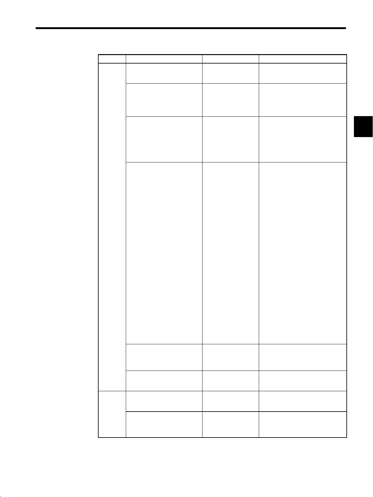
1.1 Overview of Manuals
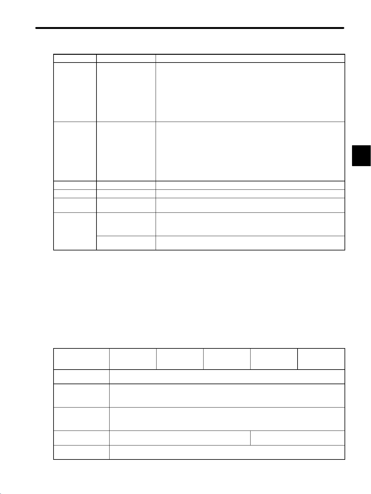
Product Manual Name Manual Number Content
CPU
Module
I/O
Modules
MEMOCON GL120
CPU10 Module
User’s Manual
MEMOCON GL120
CPU21 Module
User’s Manual
MEMOCON GL120, GL130
Software User’s Manual,
Volume 1
MEMOCON GL120, GL130
Software User’s Manual,
Volume 2
MEMOCON GL120, GL130
Software User’s Manual,
Volume 3
MEMOCON GL120, GL130
Software User’s Manual,
Volume 4
MEMOCON GL120, GL130
120-series I/O Modules
User’s Manual
MEMOCON GL120, GL130
Distributed I/O Module
User’s Manual
(MECHATROLINK)
SIEZ-C825-20.1-1 Describes the functions,
specifications, usage, and ROM
operation of the CPU10 Module.
SIEZ-C825-20.1-2 Describes the functions,
specifications, usage, and
expansion memory access
instructions of the CPU21
Module.
SIEZ-C825-20.11 Describes the following for the
GL120 and GL130:
1) Operating principles
2) I/O allocation
3) Overview of instructions
4) Instruction processing times
SIEZ-C825-20.12 Describes the programming
instructions used to create
ladder programs for the GL120
and GL130.
The following instructions are
described in other manuals.
1) Expansion Math Instructions:
Software User’s Manual (Vol.
3)
2) Process Control Instructions:
Software User’s Manual (Vol.
4)
3) CommunIcations Instructions
COM:
COM Instructions User’s
Manual FBUS:
PC Link Module User’s
Manual
MSTR:
MEMOBUS PLUS User’s
Manual
4) Motion Control Instructions
(ladder motion instructions)
Motion Module MC20
Software User’s Manual
5) Motion Language
Motion Module MC20
Software User’s Manual
SIEZ-C825-20.13 Describes expansion math
instructions (floating point math
instructions, etc.) used for the
GL120 and GL130.
SIEZ-C825-20.14 Describes process control
instructions used for the GL120
and GL130.
SIEZ-C825-20.22 Describes the functions,
specifications, and usage of the
120-Series Digital I/O Module.
SIEZ-C825-20.71 Describes the functions,
specifications, and usage of the
Distributed I/O Module for
MECHATROLINK.
1
— 1-3 —
Page 9

1
Introduction and Precautions
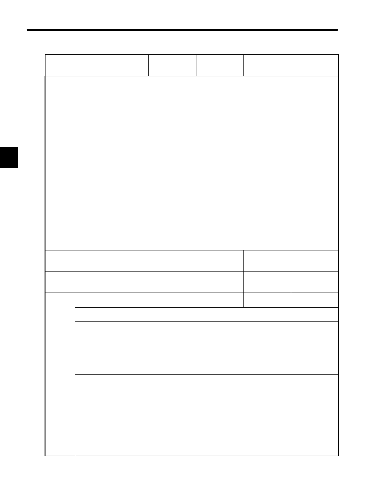
Product ContentManual NumberManual Name
Special
Purpose
Modules
Motion
Modules
HumanMachine
Interface
MEMOCON GL120, GL130
120-series High-speed
Counter Module
User’s Manual
MEMOCON GL120, GL130
Pulse Catch and Counter
Module
User’s Manual
MEMOCON GL120, GL130
Counter Module
User’s Manual
(MECHATROLINK)
MEMOCON GL120, GL130
Pulse Output Module
User’s Manual
(MECHATROLINK)
MEMOCON GL120, GL130
Motion Module MC10
User’s Manual
MEMOCON GL120, GL130
Motion Module MC15
User’s Manual
MEMOCON GL120, GL130
Motion Module MC20
Hardware User’s Manual
MEMOCON GL120, GL130
Motion Module MC20
Software User’s Manual
MEMOCON GL120, GL130
Teach Pendant TB120 for
Motion Module MC20
User’s Manual
MEMOCON GL120, GL130
MEMOSOFT for P120
Programming Panel
User’s Manual
MEMOCON GL120, GL130
MEMOSOFT
User’s Manual
MEMOCON GL120, GL130
MEMOSOFT for Windows
User’s Manual
MEMOCON GL120, GL130
Online Programmer for
P120 Programming Panel
User’s Manual
MEMOCON GL120, GL130
MEMOMAIL for P120
Programming Panel
User’s Manual
MEMOCON GL120, GL130
Online Programmer for
P140 Programming Panel
User’s Manual
FA Monitor for MEMOCON
Series ACGC4200
User’s Manual
SIEZ-C825-20.24 Describes the functions,
specifications, and usage of the
120-series High-speed Counter
Module.
SIEZ-C825-20.28 Describes the functions,
specifications, and usage of the
120-series Pulse Catch and
Counter Module.
SIEZ-C825-20.79 Describes the functions,
specifications, and usage of the
Counter Module for
MECHATROLINK.
SIEZ-C825-20.80 Describes the functions,
specifications, and usage of the
Pulse Output Module for
MECHATROLINK.
SIEZ-C825-20.41 Describes the functions,
specifications, and usage of the
One-axis Motion Module MC10.
SIEZ-C825-20.43 Describes the functions,
specifications, and usage of the
Two-axis Motion Module MC15.
SIEZ-C825-20.51 Describes the functions,
specifications, and usage of the
Four-axis Motion Module MC20.
SIEZ-C825-20.52 Describes motion control
instructions (ladder motion
instructions) and motion program
language used for the Four-axis
Motion Module MC20.
SIEZ-C825-60.3 Describes the functions,
specifications, and usage of the
Teach Pendant TB120.
SIEZ-C825-60.7 Describes the functions,
specifications, and usage of the
Programming Panel P120 (with
built-in MEMOSOFT).
SIEZ-C825-60.10 Describes the functions and
usage of the MEMOSOFT for
DOS.
SIEZ-C825-60.25 Describes the functions and
usage of the MEMOSOFT for
Windows.
SIEZ-C825-60.19 Describes the functions,
specifications, and usage of the
Online Programmer for the
GL120 and GL130.
SIEZ-C825-60.19-2 Describes the functions,
specifications, and usage of the
Online Programmer MEMOMAIL
for the GL120 and GL130.
SIEZ-C825-60.22 Describes the functions,
specifications, and usage of the
Online Programmer for the
GL120 and GL130.
SIE-C825-60.57 Describes the functions,
specifications and usage of the
FA Monitors ACGC4250/4260.
— 1-4 —
Page 10

Product ContentManual NumberManual Name
Communication
Modules
MEMOCON GL120, GL130
PC Link Module
User’s Manual
MEMOCON GL120, GL130
MEMOBUS PLUS
User’s Manual
MEMOCON GL120, GL130
MEMOBUS PLUS
SA85 Network Adapter
User’s Manual
MEMOCON GL120, GL130
MEMOBUS PLUS
BM85 Bridge/Multiplexer
User’s Manual
MEMOCON GL120, GL130
Coaxial Remote I/O System
User’s Manual
1000/2000-Series Coaxial
Remote I/O System
User’s Manual
MEMOCON GL120, GL130
Uniwire Interface Module
User’s Manual
MEMOCON GL120, GL130
Uniwire H-system Interface
Module
User’s Manual
MEMOCON GL120, GL130
Distributed I/O Driver
Module
User’s Manual
MEMOCON GL120, GL130
M-NET Module
User’s Manual
MEMOCON GL120, GL130
MEMOBUS
User’s Manual
MEMOCON GL120, GL130
COM Instructions
User’s Manual
MEMOCON GL120, GL130
Optical/Electrical
Conversion Module
User’s Manual
MEMOCON GL120, GL130
YENET 1600-D Module
User’s Manual
MEMOCON GL120, GL130
Ethernet Interface Module
User’s Manual
1.1 Overview of Manuals
SIEZ-C825-70.4 Describes the functions,
specifications, and usage of the
PC Link Module for the GL120
and GL130.
SIEZ-C825-70.5 Describes the functions,
specifications, and usage of the
MEMOBUS PLUS.
SIEZ-C825-70.6 Describes the SA85 Network
Adapter for the MEMOBUS
PLUS.
SIEZ-C825-70.7 Describes the BM85
Bridge/Multiplexer for the
MEMOBUS PLUS.
SIEZ-C825-70.8 Describes the functions,
specifications, and usage of the
Coaxial Remote I/O System for
the GL120 and GL130.
SIEZ-C825-70.9 Describes the functions,
specifications, and usage of the
Coaxial Remote I/O System for
the GL120 and GL130 using
1000 I/O and 2000 I/O
SIEZ-C825-20.26 Describes the functions,
specifications, and usage of the
120-series Uniwire Interface
Module.
SIEZC82052100 Describes the functions,
specifications, and usage of the
120-series Uniwire Interface
Module.
SIEZ-C825-20.29 Describes the functions,
specifications, and usage of the
120-series Distributed I/O Driver
Module for MECHATROLINK.
SIEZ-C825-70.12 Describes the functions,
specifications, and usage of the
M-NET Module.
SIEZ-C825-70.13 Describes the functions,
specifications, and usage of the
MEMOBUS.
SIEZ-C825-70.14 Describes the functions,
specifications, and usage of the
COM instructions. It also
describes the specifications and
usage of the MEMOBUS
Module.
SIEZ-C825-70.18 Describes the functions,
specifications, and usage of the
Optical/Electrical Conversion
Module.
SIEZ-C825-70.20 Describes the functions,
specifications, and usage of the
YENET 1600-D Module.
SIEZ-C825-70.21 Describes the functions,
specifications, and usage of the
Ethernet Interface Module.
1
— 1-5 —
Page 11

1
Introduction and Precautions
Product ContentManual NumberManual Name
Communication
Modules
Other
Products
• Thoroughly check the specifications and conditions or restrictions of the product before
use.
MEMOCON GL120, GL130
FIX Ethernet MEMOBUS
Driver (YME)
User’s Manual
MEMOCON GL120, GL130
Traceback
User’s Manual
SIEZ-C825-70.22 Describes the functions,
specifications, and usage of the
FIX Ethernet MEMOBUS Driver.
SIEZ-C825-60.10-4 Describes the functions,
specifications, and usage of the
Traceback.
— 1-6 —
Page 12

1.2 Precautions
This section outlines general precautions that apply to using this manual and the
product. You must read this section first before reading the remainder of the
manual.
1.2 Precautions
1.2.1 Safety Precautions 1-7...............................................
1.2.2 Installation Precautions 1-8...........................................
1.2.3 Removal Precautions 1-12............................................
1.2.4 Wiring Precautions 1-13...............................................
1.2.5 Applications Precautions 1-16..........................................
1.2.6 Maintenance 1-18....................................................
1.2.1 Safety Precautions
• The GL120 and GL130 were not designed or manufactured for use in devices or systems
directly related to human life. Users who intend to use the product described in this manual
for special purposes such as devices or systems relating to transportation, medical, space
aviation, atomic power control, or underwater use must contact Yaskawa Electric Corporation beforehand.
• This product has been manufactured under strict quality control guidelines. However, if this
product is to be installed in any location in which a failure of GL120 and GL130 involves a life
and death situation or in a facility where failure may cause a serious accident, safety devices MUST be installed to minimize the likelihood of any accident.
1
• Any illustrations, photographs, or examples used in this manual are provided as examples
only and may not apply to all product to which this manual is applicable.
• The products and specifications described in this manual or the content and presentation of
the manual may be changed without notice to improve the product and/or the manual. A
new version of the manual will be released under a revised manual number when any
changes are made.
• Contact your Yaskawa representative or a Yaskawa office listed on the back of this manual
to order a new manual whenever this manual is damaged or lost. Please provide the manual
number listed on the front cover of this manual when ordering.
• Contact your Yaskawa representative or a Yaskawa office listed on the back of this manual
to order new nameplates whenever a nameplate becomes worn or damaged.
• Yaskawa cannot guarantee the quality of any products which have been modified. Yaskawa
assumes no responsibility for any injury or damage caused by a modified product.
— 1-7 —
Page 13
Introduction and Precautions
1.2.2 Installation Precautions
1.2.2 Installation Precautions
Abide by the following precautions when installing GL120 and GL130 systems.
!
Caution The installation environment must meet the environmental conditions given in product cata-
logs and manuals. Using the GL120 and GL130 in environments subject to high temperatures, high humidity, excessive dust, corrosive gases, vibration, or shock can lead to electrical shock, fire, or faulty operation. Do notuse the GL120 and GL130 in the following locations.
1
• Locations subject to direct sunlight or ambient temperatures not between 0 and 60 _C.
• Locations subject to relative humidity in excess of 95%, or condensation because of
rapid changes in humidity.
• Locations subject to corrosive or flammable gas.
• Locations that would subject the GL120 and GL130 to direct vibration or shock.
• Locations subject to contact with water, oil, chemicals, etc.
!
Caution Install the GL120 and GL130 as described in this product manual. Improper installation can
cause product failure, malfunctions, or Modules or other components to fall off.
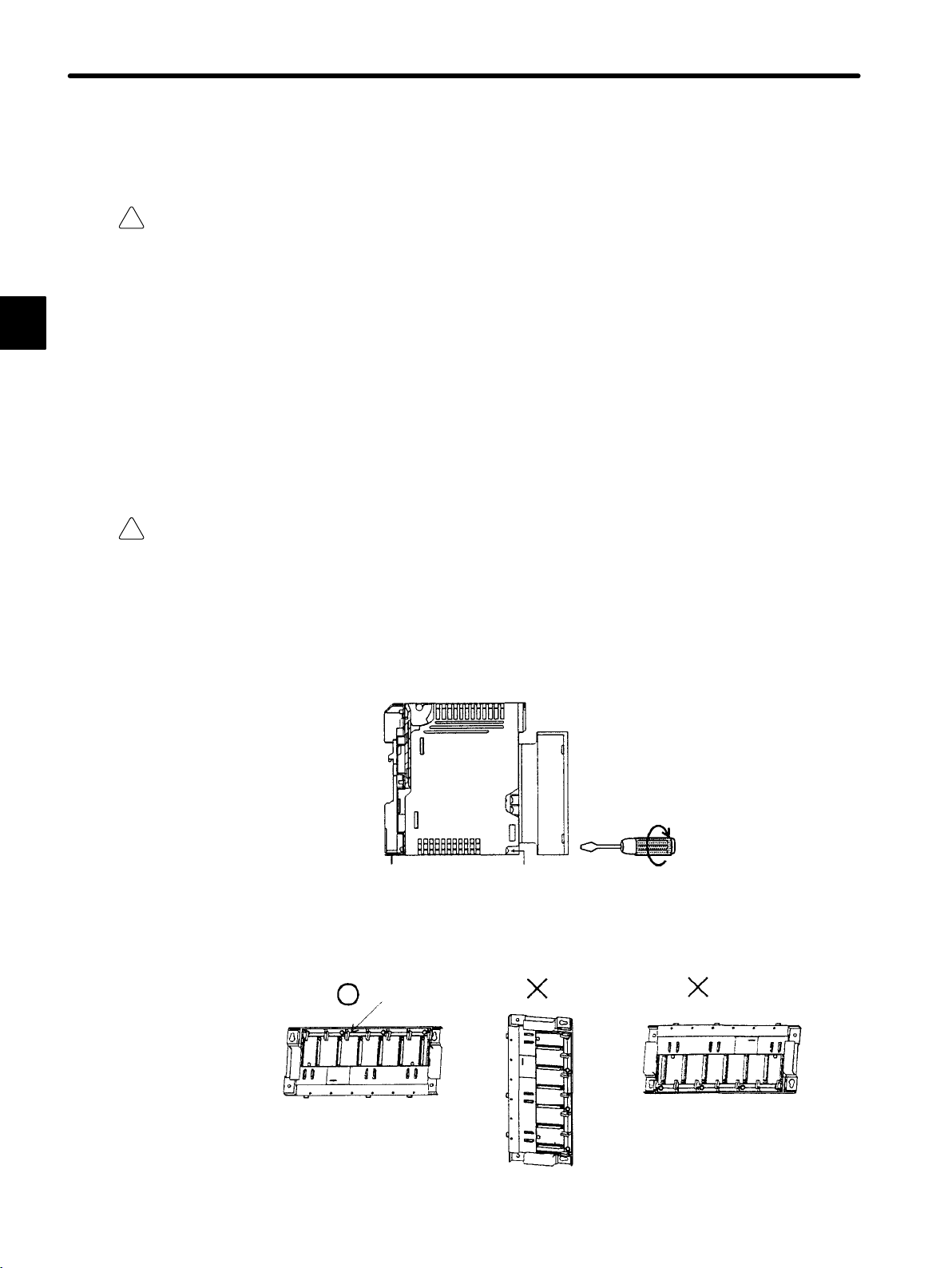
1) Make sure that all mounting screws are securely tightened.
Make sure that all installation screws for Modules or terminal block for field connection
are securely tightened so that they do not become loose. Loose screws will cause failures in the GL120 and GL130.
Power
Supply
Module
Module mounting screw
2) Install Mounting Bases in the correct direction. Faulty or inappropriate installation may
result in detachment, failure, or malfunction.
Module hooks
Install Mounting Base perpendicularly so
that the Module hooks face upwards.
— 1-8 —
Page 14

1.2 Precautions
!
Caution
!
Caution Connector covers are attached to the Module connectors on the Mounting Base. Leave the
!
Caution When installing the Power Supply Module, turn OFF the power supply to the field wiringtermi-
Never install a Mounting Base on the DIN track when transporting over long distances or
when the control panel which houses the GL120 or GL130 will be used in an environment
subject to excessive vibration. In such cases, install the Mounting Base directly onto a steel
installation plate.
If the Mounting Base is installed on DIN track, it may fall off if subject to strong shock or
vibration.
Module connectors attached to the connector covers when mounting the Mounting Base so
that foreign matter does not enter the Module connectors during mounting operations.
The GL120 and GL130 may malfunction if any foreign matter enters a Module connector.
nals.
1
Installing the Power Supply Module while the power is being supplied may damage the
Module or cause malfunction of the GL120 and GL130.
!
Caution When installing the CPU or the Expander Module, turn OFF the power supply to all Power
Supply Modules.
Installing the CPU or the Expander Module while the power is being supplied to Power
Supply Modules may damage the Module or cause malfunction of the GL120 and GL130.
!
Caution When installing the terminal block for the AC I/O Modules, turn OFF the AC power supply to
the AC I/O Modules for input signal or driving loads.
Installing a terminal block with AC power to the external power supply terminal of the AC
I/O Modules may cause an electric shock at touching the power supply terminals.
!
Caution Make sure that all mounting screws for the terminal block are securely tightened.
Make sure that all mounting screws for the terminal block are securely tightened so that
they do not become loose. Loose screws may cause malfunctioning of the GL120,
GL130.
!
Caution Male sure that all cable connectors for the Module are securely inserted and tightened.
Insufficient insertion and/or looseness may cause malfunction of the GL120 and GL130.
— 1-9 —
Page 15

1
Introduction and Precautions
1.2.2 Installation Precautions cont.
!
Caution
!
Caution Mount the Modules mentioned in the table below on local channel racks.
Mount the Modules mentioned in the table below on CPU racks (racks with CPU Modules).
Mounting these Modules on any other racks may damage the Modules or cause a malfunction of the GL120 and GL130.
Modules to be Mounted on CPU Rack Model No.
Remote I/O Driver Module JAMSC-120CDR13100
2000-series Remote I/O Driver Module JAMSC-120CDR13110
PC Link Module JAMSC-120NFB23100
Ethernet Interface Module JAMSC-120NET12100
Mounting these Modules on remote channel racks may damage the Modules or cause a
malfunction of the GL120 and GL130.
Modules to be Mounted on Local Channel Rack Model No.
MEMOBUS Module (RS-232) JAMSC-120NOM13100
MEMOBUS Module(RS-422) JAMSC-120NOM13110
!
Caution When installing the Modules that do not support hot swapping, turn OFF the power supply to
Power Supply Modules.
Installing the Modules that do not support hot swapping while the power is being supplied
to Power Supply Modules may damage the Module or cause malfunction of the GL120
and GL130.
Modules that Do Not Support Hot Swapping Model No.
Remote I/O Driver Module JAMSC-120CDR13100
2000-series Remote I/O Driver Module JAMSC-120CDR13110
!
Caution
When connecting the cables connected to the Ethernet Interface Modules, turn OFF the power supply to the Power Supply Modules on the racks where the Ethernet Interface Modules
are mounted.
Connecting the cables while power is being supplied to the Power Supply Modules may
damage the Ethernet Interface Module or cause a malfunction of the GL120 and GL130.
!
Caution Mount the MC20 Module on a CPU Rack(a rack with CPU Module).
Installing the MC20 Module on any other rack may damage the Module or cause the malfunction of the GL120 and GL130.
!
Caution When using the absolute position detecting function with the MC15 Module, it must be
mounted on the CPU Rack (a rack with CPU Module).
Installing the MC15 Module on any other rack may damage the Module or cause the malfunction of the GL120 and GL130.
— 1-10 —
Page 16

1.2 Precautions
!
Caution
!
Caution When connecting the cables to the Motion Module, turn OFF the power supply to the Power
When installing the Motion Module, turn OFF the power supply to the Power Supply Module
on the rack with the Motion Module mounted.
Installing the Motion Module while the power is being supplied to the Power Supply Module may damage the Module or cause malfunction of the GL120 and GL130.
Supply Module on the rack with the Motion Module mounted.
Connecting cables to a Motion Module while the power is being supplied may damage
the Module or cause malfunction of the GL120 and GL130.
!
Caution When connecting the Rack-to-rack I/O cables to the Motion Module, turn OFF the power Sup-
ply to all Power Supply Modules.
Connecting the cables while the power while the power is being supplied may damage
the Module or cause a malfunction of the GL120 and GL130.
!
Caution The total length of the rack-to rack I/O cable for each station is always 6.0 m or less.
If the total length of the cables exceeds 6.0 m, operational errors may occur at the station.
!
Caution Make sure that all cable connectors for the Module are securely inserted and tightened.
Insufficient insertion and/or looseness may cause malfunction of the GL120 and GL130.
!
Caution Do not remove the connector covers from the Module connectors on the Mounting Base slots
where no Modules are installed.
1
The GL120 and GL130 may malfunction if any foreign matter enters a Modules connector.
!
Caution Make sure that all mounting screws for the Module are securely tightened.
Make sure that all mounting screws for the Modules are securely tightened so that they
do not become loose. Loose screws may cause malfunction of the GL120 and GL130.
!
Caution Do not mount more than one Power Supply Modules on a single Mounting Base.
Mounting more than one Power Supply Modules on a single Mounting Base may damage
the Power Supply Module and cause malfunction of the GL120 and GL130.
!
Caution
Do not mount more than CPU Modules and Expander Module on a single Mounting Base.
Mounting more than CPU Modules and Expander Module on a single Mounting Base
may damage the CPU Modules and Expander Module or cause malfunction of the
GL120 and GL130.
— 1-11 —
Page 17

Introduction and Precautions
1.2.3 Removal Precautions
1.2.3 Removal Precautions
!
Caution Always turn OFF the power to field wiring terminals before removing the Power Supply Mod-
ule.
Removing the Power Supply Module while power is supplied to field wiring terminals may
damage the Power Supply Module or cause malfunction of the GL120 and GL130.
1
!
Caution Always turn OFF the power to the Power Supply Module before removing the CPU Modules
or Expander Module.
Removing the CPU Modules and Expander Module while power is supplied to Power
Supply Module may damage the CPU Modules and Expander Module or cause malfunction of the GL120 and GL130.
!
Caution
!
Caution When inserting or removing an AC I/O Module while the AC power supply is turned ON, install
!
Caution Always turn OFF the power to the Power Supply Module before removing the Modules that do
Always turn OFF the AC power supply to the AC I/O Modules for inputting signal or for driving
loads before removing the terminal block from the AC I/O Modules.
Removing a terminal block with AC power supply to the external power supply terminal of
the AC I/O Modules may cause an electric shock at touching the power supply terminals.
a safety switch for each Module and always turn this safety switch OFF to turn OFF the AC
power supply to the Module.
Inserting or removing an AC I/O Module while the AC power supply is being supplied may
result in an electric shock at touching the power supply terminals.
not support hot swapping.
Removing the Modules that do not support hot swapping while the power is being supplied to the Power Supply Module may damage the Modules or cause a malfunction of
the GL120 and GL130.
Modules that Do Not Support Hot Swapping Model No.
Remote I/O Driver Module JAMSC-120CDR13100
2000-series Remote I/O Driver Module JAMSC-120CDR13110
!
Caution Always turn OFF the power to Power Supply Modules on the rack having the Ethernet I/F
Module Mounted, before removing the cables connected to the Ethernet I/F Module.
Removing cables connected to the Ethernet I/F Module while power is being supplied to
Power Supply Module may damage the Modules or cause malfunction of the GL120 and
GL130.
— 1-12 —
Page 18

1.2 Precautions
!
Caution
!
Caution Always turn OFF the power to Power Supply Module on the rack, having the Motion Module
!
Caution Always turn OFF the power to Power Supply Module before removing the Rack−to rack I/O
Always turn OFF the power to Power Supply Module on the Rack, having the Motion Module
mounted, control power of Servo Amp, and power supply for the external I/O devices, before
removing cables to the Motion Module.
Removing cables connected to the Motion Module while power is being supplied to these
devices may damage the Motion Module or cause malfunction of the GL120 and GL130.
mounted, control power of Servo Amp, and power supply for the external I/O devices before
removing the Motion Module.
Removing the Motion Module while the power is being supplied to these devices may
damage the Motion Module or cause malfunction of the GL120 and GL130.
cables connected to the Expander Module.
1
Removing cables connected to the Expander Module while power is being supplied to
Power Supply Module may damage the Expander Module or cause malfunction of the
GL120 and GL130.
1.2.4 Wiring Precautions
!
Caution Connect the correct power supply for the required ratings.
Connecting unsuitable power supplies may result in fires.
!
Caution Wiring must be performed by qualified personnel.
Wrong or inappropriate wiring may result in fire, product failure, or electric shock.
!
Caution Wire power supply wires to the DC Power Supply Module with the correct polarity.
Wiring with incorrect polarity may result in damage to the DC Power Supply Module.
!
Caution
Connect power supplies of the same phases to the common 1 and common 2 of the AC I/O
Module.
If power supplies of different phases are connect, overheating or fire may occur.
— 1-13 —
Page 19

1
Introduction and Precautions
1.2.4 Wiring Precautions cont.
!
Caution
!
Caution When using one of the following Output Modules, connect an external fuse corresponding to
When inserting or removing an AC I/O Modules while the AC power supply is turned ON,
install a safety switch for each Module and always turn this safety switch OFF to turn OFF the
AC power supply to the Module.
the specifications of the load and in series with the load.
Inserting or removing an AC I/O Modules while the AC power supply is being supplied
may result in an electric shock at touching power supply terminals.
a) 100/200-VAC 8-point Output Module (Model No.: JAMSC-120DAO83000)
(Model No.: JAMSC-120DAO83009)
b) 100/200-VAC 16-point Output Module (Model No.: JAMSC-120DAO84300)
(Model No.: JAMSC-120DAO84309)
c) 12/24-VDC 16-point Output Module (sinking) (Model No.: JAMSC-120DDO34310)
d) 12/24-VDC 16-point Output Module (sourcing) (Model No.: JAMSC-120DDO34320)
e) 12/24-VDC 32-point Output Module (sinking) (Model No.: JAMSC-120DDO35410)
f) 12/24-VDC 64-point Output Module (sinking) (Model No.: JAMSC-120DDO36410)
g) Relay Contact 16-point Output Module (Model No.: JAMSC-120DRA84300)
(Model No.: JAMSC-120DRA84309)
Not connecting an external fuse may result in fire, damage to the device, or damage to
output circuit due to an overload or a short-circuit at the load.
!
Caution Ground the protective ground terminal to a resistance of 100 Ω max.
Not grounding the protective ground terminal may result in electric shock or malfunction.
Insert the Interface Cables Properly
• Insert the connectors of the various interface cables that are to be connected to GL120
and GL130 into the communication ports and secure them properly.
Improper insertion of interface cables may cause operational errors in the GL120 and
GL130.
— 1-14 —
Page 20
1.2 Precautions
Power Supply Noise Reduction
• Prevent noise from penetrating into the product by installing an isolation transformer or
a noise filter for the external power supply.
Noise from power supply may result in the malfunctioning of GL120 and GL130.
Select, Separate, and Lay External Wiring Correctly
• I/O lines connecting external devices to the 120-series I/O Modules must be selected
based on the following considerations: mechanical strength, resistance to noise, wiring
distance, signal voltage, etc.
• I/O lines must be separated from power lines both inside and outside the control panel
to minimize theaffects of noise. Faulty operation may result if I/O lines are not sufficiently separated from power lines.
1
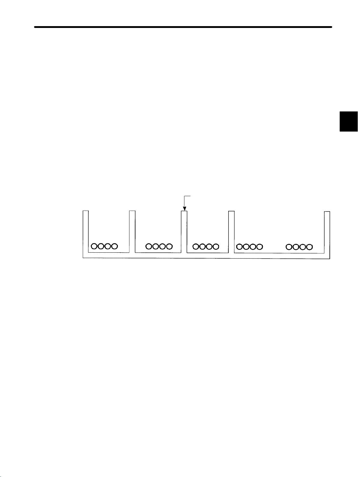
Example of external wiring separation
Power lines General control
circuit cables
Control panel separator
Digital I/O
signal cables
Analog I/O
signal cables
Pulse input
signal cables
— 1-15 —
Page 21

1
Introduction and Precautions
1.2.5 Applications Precautions
1.2.5 Applications Precautions
!
WARNING
!
WARNING
Do not touch terminals while the power is ON.
Construct an emergency stop circuit and an interlock circuit outside of the GL120 and GL130.
Install an Emergency Stop Circuit Outside the GL120 and GL130.
Touching live terminals may cause electric shock.
The absence of emergency stop and interlock circuits may result in machine damage or
accidents should the GL120 or GL130 fail.
An emergency stop circuit for the control system should not be constructed using the ladder programming in the GL120 and GL130. Always construct the emergency stop circuit
externally using a relay circuit, as shown in the figure below.
Use an N.C. contact (mechanical contact) in the emergency stop switch. The main power
supply to the servo must be cut off by pressing the switch.
Failure to provide an emergency stop circuit as described above, may result in failure of
the emergency stop when input circuits fail or cables break, and may cause machine
damage or injury.
Control power
supply OFF
Emergency stop
Noise filter
Control power supply ON
ESP-TBOX
Noise filter
Servo OFF
Servo ON
Surge absorber
— 1-16 —
Control signal to MC Module
Encoder
Servo motor
Page 22
1.2 Precautions
External Interlocks for the GL120 and GL130
Externally connect an interlock to the GL120 and GL130 if there is any chance that
GL120 and GL130 failure could result in bodily harm or equipment damage.
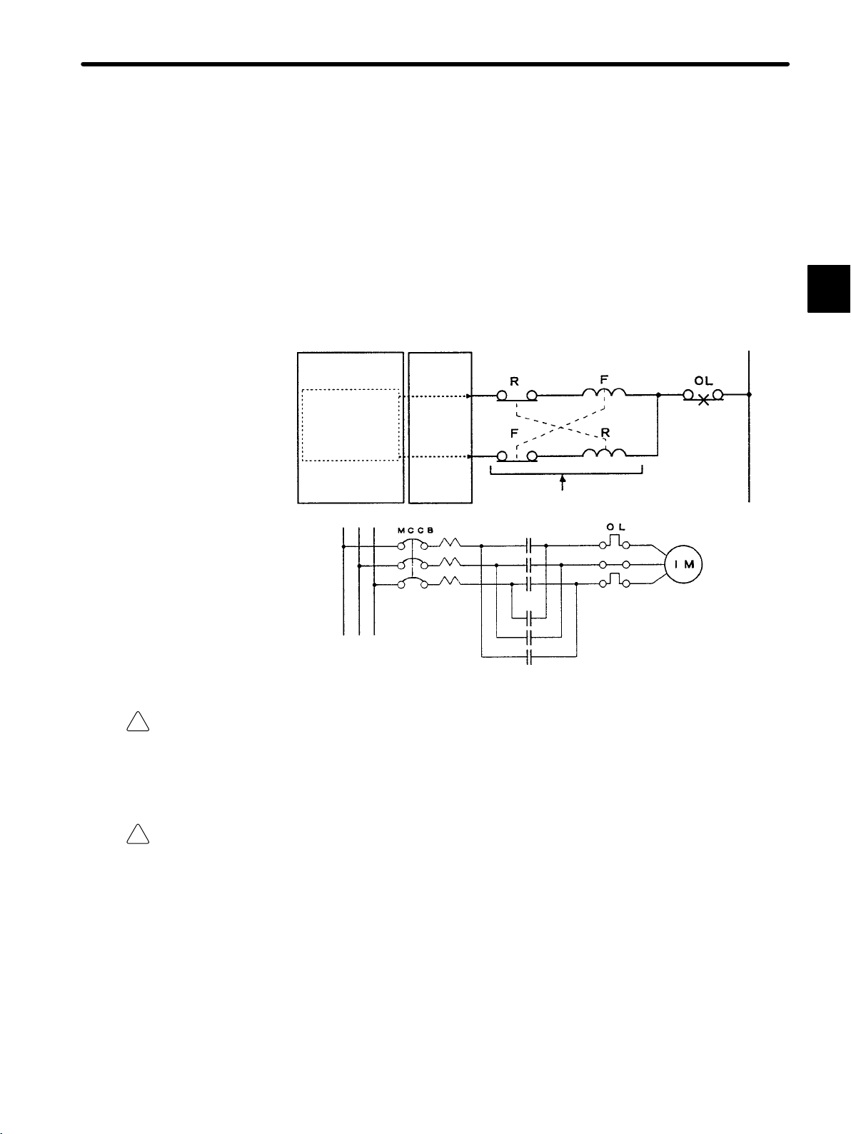
Always use an external interlock system as shown in the following example when reciprocal operations (e.g., forward and reverse directions) are being performed with a motor.
An interlock is generally programmed in the GL120/GL130 ladder program to ensure that
forward and reverse signals are not simultaneously output. An external interlock circuit
must also be provided using the auxiliary contacts of electromagnetic contactors.
CPU Module Output Module
Ladder logic program
1
!
Caution
Output program with an
interlock which prohibit
simultaneous forward
and reverse runs
Electric interlock using the auxiliary contacts
of electromagnetic contactors
F (Forward run)
R (Reverse run)
Contact of overcurrent protection
device.
Induction motor
Always make sure that power supply to the external power supply terminals (AC1, AC2) is
OFF when operating the input voltage selector switch of Power Supply Module.
Operating the input voltage selector switch of Power Supply Module while power is being
supplied to the external power supply terminals may damage the Module.
!
Caution Set the Rack numbers according to the following rules.
If the Rack No. is not set according to the following rules, the PLC system will not run
normally. In other words, it may result in failure of the CPU Module to run, communication
errors, I/O process errors, etc.
• Set each Rack No. between 1 and 4 (rotary switch No: between 0 and 3).
• Always set the Rack No. where CPU Module or Remote I/O Receiver Module is
installed to 1 (rotary switch: 0).
• Do not use the same Rack No. more than once at the same station.
— 1-17 —
Page 23

1
Introduction and Precautions
1.2.6 Maintenance
1.2.6 Maintenance
!
WARNING
!
Caution
!
Caution Do not replace any of the built-in fuses.
Do not reverse the positive and negative terminals, charge, dismantle, heat, throw into fire or
short-circuit batteries.
Do not disassemble or modify Modules and Mounting Bases.
Monitor the Life of Battery
These may cause explosion and/or ignition.
Doing so can cause fires, product failure, or malfunction.
Replacing built-in fuse by users may result in failure or malfunction of the Power Supply
Modules. Built-in fuse must be replaced by a Yaskawa service department.
• Monitor the life of the built-in battery in the CPU Module. If the “BAT ALM” indicator lights,
replace the battery with a new one (replacement battery: BR-2/3A-1) within 2 weeks.
Delay in replacing the battery may result in the memory content loss of the ladder program and the motion program in the CPU Module and any Motion Modules.
• When the BAT Module’s “ALARM1” indicator lights, be sure to replace the battery with an
ER6VC3N replacement battery within one week. Delay in replacing the battery may result
in the memory content loss of the rotation data in the absolute encoder.
Regularly Overhaul Power Supply Modules
• Overhaul the Power Supply Module once every 5 years.
Deterioration of parts such as smoothing capacitors may result in malfunctioning of power supply sections. When a Power Supply Module is used in one of the following environment, overhaul more frequently.
• When used in places subject to high temperature or humidity, or subject to high variations in these.
• When variations in the power supply (voltage, frequency, wave-form distortion, etc.) or
load are high.
• When subject to bad storage environments before use, including long-term storage or
stoppage.
— 1-18 —
Page 24

1.3 Using this Manual
This Manual is compiled for the following readers:
1) Those estimating purchase prices of GL120 or GL130 systems.
1.3 Using this Manual
2) Those considering application of the GL120 or GL130.
3) Those designing control panels for the installation of the GL120 or GL130.
4) Those creating control panels to include the GL120 or GL130.
5) Those inspecting control panels on which GL120 or GL130 has been installed.
6) Those testing or adjusting control panels on which GL120 or GL130 has been installed.
7) Those maintaining control panels on which the GL120 or GL130 has been installed.
• Meaning of Basic Terms
In this manual, the following terms are defined as follows, unless otherwise specified:
• PLC=Programmable (Logic) Controller
• PP=Programming Panel
1
• GL120, GL130=MEMOCON GL120 and/or MEMOCON GL130 Program-
mable Controller
— 1-19 —
Page 25

Overview
2
This chapter provides an outline of the MEMOCON GL120 and GL130, including system configuration examples, main modules, etc.
2.1 Overview of the MEMOCON GL120 and
GL130 2-2.................................
2
— 2-1 —
Page 26

2
Overview
2.1 Overview of the MEMOCON GL120 and GL130
This section outlines the MEMOCON GL120 and GL130.
1) The MEMOCON GL120 (abbreviated GL120) and MEMOCON GL130 (abbreviated
GL130) are programmable controllers (PLCs) developed to succeed the MEMOCONSC GL60 Series. The MEMOCON-SC GL60 Series has been well received and is very
popular for key controllers in FA systems. The GL120 and GL130 are mid- to large-capacity programmable controllers. They provide greater compactness, higher quality, and
higher performance while retaining the functions of the GL60 Series. The GL120 and
GL130 have program memory capacity of 8K words, 16K words, 32K words, and 40K
words, making the GL120 a mid-capacity controller and the GL130 a large-capacity controller.
2) The GL120 and GL130 can be used as high-speed machine controllers or as key controllers for various automatic devices, and can be applied to the following control:
D Sequence control D Motion control D Process control D Computational control
3) The difference between the GL120 and GL130 lies in the CPU Module that is used. A
PLC using the CPU20 CPU Module is a GL120, while a PLC using a CPU30 CPU Module
is a GL130. All devices other than the CPU Module can be used in both PLCs.
Example 1
Example of system configuration for MEMOCON GL120
— 2-2 —
Page 27

2.1 Overview of the MEMOCON GL120 and GL130
Example 2
Example of system configuration for MEMOCON GL130
2
PS10: Power Supply Module
(7 A)
CPU20: CPU Module (16 KW) DO: Digital Output Module MB12: 12-slot Mounting Base
CPU30: CPU Module (32 KW) MC20: Four-axis Motion Module
DI: Digital Input Module EXP: Expander Module
4) The following table shows the main Modules and other devices used in the GL120 and
GL130. Any itemslisted as “Optional” in the Use column may be used as required according to the system control specifications of the GL120 or GL130.
Table 2.1 Main GL120 and GL130 Modules and other Products
Use Name Features
Required Power Supply
Module
Required CPU Module 1) Stores the user program, solves the program based on the information
Supplies DC power to various Modules to operate them.
from the input section, and outputs the results to the output section.
There are 5 types of CPU Modules, namely the CPU10, CPU20,
CPU21, CPU30, and CPU35.
2) Equipped with 1 MEMOBUS port (slave, RS-232C).
(CPU20, CPU21, CPU30, CPU35)
3) Equipped with 1 MEMOBUS PLUS port
(CPU20, CPU21, CPU30, CPU35)
4) Execute the ROM operation.
(CPU10, CPU21)
— 2-3 —
Page 28

Overview
Use FeaturesName
Optional Communications
Module
1) Remote I/O Driver Module:
Used as the master station of a Remote I/O system.
2) Remote I/O Receiver Module:
Used as the slave station of a Remote I/O system.
3) 2000-Series Remote I/O Driver Module:
Used as the master station of a Remote I/O system for 2000 I/O.
4) MEMOBUS Module (RS-232):
Used to increase the number of RS-232C MEMOBUS ports.
2
5) MEMOBUS Module (RS-422):
Used to increase the number of RS-422 MEMOBUS ports.
6) PC Link Module:
Used for high-speed communications between PLCs.
7) Uniwire Interface Module:
Used as the master station of a Uniwire system.
8) Uniwire H-system Interface Module:
Used as the master station of a Uniwire H-system.
9) Distributed I/O Driver Module:
Used as the master station of the VINUS I/O system.
10) M-NET Module:
Used for high-speed communications between PLCs.
11) YENET 1600-D Module:
Used for high-speed communications between PLCs.
12) Ethernet Interface Module:
Used for communications between PLCs.
13) Optical/Electrical Conversion Module:
Used for an Optical PC Link system or an Optical Remote I/O system.
Optional I/O Module 1) Digital Input Module:
Used to input digital signals.
2) Analog Input Module:
Used to input analog signals.
3) Digital Output Module:
Used to output digital signals.
4) Analog Output Module:
Used to output analog signals.
— 2-4 —
Page 29
Use FeaturesName
Optional Special Purpose
Optional Motion Module 1) Four-axis Motion Module:
Optional Expander Module Used to expand the number of racks.
Required Mounting Base Used to install Modules.
Optional Rack-to-rack I/O
Required (one
or the other)
Module
Cable
Programming Panel
P120
MEMOSOFT A general-purpose personal computer software application for online or
1) High-speed Counter Module (1 channel):
Used to count high-speed pulses.
2) Pulse Catch Module (16 channels):
Used to read input signals that are ON for less than one scan time.
3) Register I/O Module:
Used to input/output the signal of the numerical value.
Used for 4-axis motion control.
2) One-axis Motion Module:
Used for 1-axis motion control.
3) Two-axis Motion Module:
Used for 2-axis motion control.
Used to connect between Expander Modules of adjacent racks.
1) A dedicated programming panel for MEMOCON PLCs.
2) Used for online or offline programming of the GL120 and GL130.
offline programming of the GL120 and GL130. (Software package)
2.1 Overview of the MEMOCON GL120 and GL130
2
5) The difference of the GL120 and GL130 lies in the difference in specifications of the CPU
Modules. The following table shows the specifications of the CPU10, CPU20, CPU21,
CPU30, and CPU35 Modules. The main differences in specifications of the CPU Modules lies in their program memory capacities, the numbers of digital I/O points and scan
times.
Table 2.2 CPU Module Summary Specifications
Item CPU10
Execution control
method
I/O connection
method
I/O control method 1) Synchronous refresh
CPU General-purpose 16-bit microprocessor General-purpose 32-bit
Programming
language
(DDSCR-
120CPU14200)
Cyclic scan method
1) Direct I/O
2) Remote I/O
2) Direct (direct I/O)
Ladder diagram
CPU20
(DDSCR-
120CPU34100)
CPU21
(DDSCR-
120CPU34110)
CPU30
(DDSCR-
130CPU54100)
microprocessor
130CPU54110)
CPU35
(DDSCR-
— 2-5 —
Page 30
Overview
be
2
Item CPU35
Types and number
of instructions
CPU20: 166
CPU30: 166
CPU35: 166
CPU21: 169
CPU10: 165
CPU10
(DDSCR-
120CPU14200)
1) Basic instructions: 16
2) Math operations: 25
3) Data manipulation instructions: 48
4) System status monitoring instruction: 1
5) Sequence control instructions: 3
6) Program control instructions: 7
7) I/O control instructions: 2
8) Communications instructions: 9 (CPU10: 8)
9) Motion control instructions: 22
10) Expansion math instructions: 32
11) Process control instruction: 1
CPU20
(DDSCR-
120CPU34100)
CPU21
(DDSCR-
120CPU34110)
CPU30
(DDSCR-
130CPU54100)
(DDSCR-
130CPU54110)
12) Expansion memory access instructions: 2 (CPU21)
Scan time Ladder logic program:
Program memory
capacity
Maximum
number
of input
and
output
points
Digital
I/O
Register
I/O
Local
I/O
Remote
I/O
Approx. 1 ms for 1K-word program
16K words
(1 word = 24 bits)
1,024 points (1 point = 1 bit) *1 4,096 points (1 point = 1 bit) *1
512 registers (1 register= 16 bits) * 2
1) Number of channels: 1
2) Number of racks: 4 racks (including CPU rack)
3) Number of mountable I/O Modules: 54
The total number of points, including remote I/O points, must not exceed the limits
indicated at * 1 and * 2, above.
1) Number of channels: 2
2) Number of stations per channel: 15
3) Number of racks per station: 4
4) Number of I/O points per station:
(Digital input points ÷ 8) + (register input points × 2) ± 512 bytes
(Digital output points ÷ 8) + (register output points × 2) ± 512 bytes
The total number of points, including local I/O points and remote I/O points of other
remote stations, must not exceed the limits indicated at * 1 and * 2, above.
Ladder logic program:
Approx. 0.6 ms for 1K-word
program
32K words
(1 word = 24
bits)
40K words
(1 word = 24
bits)
— 2-6 —
Page 31

2.1 Overview of the MEMOCON GL120 and GL130
Item CPU35
Maximum number
of coils, relays, etc.
Maximum capacity
of data register
CPU10
(DDSCR-
120CPU14200)
1) When the number of data registers is the initial value, the following condition must be
met:
(Number of coils) + (Number of relays) ≤ 65,520.
2) The maximum value for each reference can be freely set within the above limit from the
Programming Panel (Unit: point (1 point = 1 bit)).
Item
Coils 16 to 65,472
Link coils 0 to 4,096
MC coils 0 to 512
MC control coils 0 to 320
Input relays 16 to 65,472
MC relays 0 to 512
MC control relays 0 to 512
M code relays 0 to 192
1) When the number of coils and relays is the initial value, the number of words of holding
registers plus the number of words of constant registers plus the number of words of link
registers must not exceed 25,998.
2) The maximum value for each reference can be freely set within the above limit from the
Programming Panel (Unit: word (1 word = 16 bits)).
Holding register 1 to 25,995
Constant register 1 to 4,096
Link register 0 to 4,096
CPU20
(DDSCR-
120CPU34100)
Setting range
Setting range
CPU21
(DDSCR-
120CPU34110)
CPU30
(DDSCR-
130CPU54100)
Setting
unit
1,024
Setting
unit
1,024
Defaults Example
16
8,192 57,328 65,472
2,048 2,048 0
256
160
16
1,024 4,096 16
256
256
96
Defaults
1
9,999 19,854 25,995
1
4,096 4,096 1
2,048 2,048 0
(DDSCR-
130CPU54110)
1
512 512 0
320 320 0
512 512 0
512 512 0
192 192 0
Example1Example
Example
2
2
2
— 2-7 —
Page 32

Overview
Previous node
6) Figure 2.2 shows GL120 and GL130 system configurations.
MEMOBUS PLUS Cable
HUB
Next node
2
GL130
Programing Panel P120C
Remote I/O Systems
D Two systems per PLC
D Coaxial cable
D 4 Mbps max.
D 1 km max.*
D 15 stations max.
A
MB10
W0203-02
05
MB10
Remote I/O Cable
A
A
MB10
A
T
C
M
PC Link Cable
Station 1
W0100-02
A
EXPI/OI/OCPU30PS10 LNC
EXPI/OI/OI/OI/OI/OI/OI/OI/OPS
EXPI/OI/OI/OI/OI/OI/OI/OPS05RRC
EXPI/OI/OI/OI/OI/OI/OI/OPS05RRC
Next station
Local
channel
Rack 1
(CPU Rack)
MEMOBUS
PLUS Networks
D One network per PLC
D Twisted-pair cable
D 1 Mbps (fixed)
Local
channel
D Without Repeater
450 m max.
Rack 2
Rack 1
Rack 1
32 nodes max.
D With Repeater
1,800 m max.
64 nodes max.
PC Link system
D Two systems per PLC
D Coaxial cable
D 4 Mbps max.
D 1 km max.
D 32 stations max.
R
T
C
M
MEM
RDC
422
MP
M
Can be extended up to Rack 4.
T
C
M
R
T
C
Station 1 of remote channel 1
Can be extended up to Rack 4.
Station 15 of remote channel 1
MB10
M
Can be extended up to Rack 4.
Figure 2.1 Outline of GL120/GL130 System Configuration
* The transmission distance varies according to the baud rate and specifications of the coax-
ial cable. For example, if the baud rate is 4 Mbps and the 12C-5AF Coaxial Cable is used, it
is possible to transmit up to 1 km max.
— 2-8 —
Page 33

2.1 Overview of the MEMOCON GL120 and GL130
co ca
Previous node
Previous station
(DOS computer running
MEMOSOFT)
GL120
A
MB12
W0202-02
MB12
05
HUB
MEMOBUS PLUS Cable
Station 2
T
C
M
MEM
LNC
232
MP
M
M
PC Link Cable
MC20MC20
Next node
A
W0100-02
Can be extended up to Rack 4.
I/OI/O
Next station
Local channel
Rack 1
EXPI/OCPU20PS10
(CPU Rack)
Local channel
Rack 2
EXPI/OI/OI/OI/OI/OI/OI/OI/OPS
2
1) Legend
PS10: Power Supply Module
(7 A)
PS05: Power Supply Module
(3 A)
CPU20: CPU Module (16 KW) EXP: Expander
CPU30: CPU Module (32 KW) MB10:
RDC: Remote I/O Driver
Module
RRC: Remote I/O Receiver
Module
LNC: PC Link Module W0202-02: MEMOBUS
MEM232: MEMOBUS Module
(RS-232)
MEM422: MEMOBUS Module
(RS-422)
MC20: 4-axis Motion
Module
I/O: Input/Output
Module
Module
10-slot Mounting
Base
MB12:
W0100-02:
12-slot Mounting
Base
Rack-to-rack I/O
Cable
Cable
W0203-02: MEMOBUS
Cable
MEMOSOFT: Programming
device
HUB: Hub Module
T: T-adapter
R:
Terminator
A: Conversion
Adapter
P: MEMOBUS
PLUS port
M: MEMOBUS
port
C: Coaxial cable
communications port
2) The following five types of Mounting Base are available. Up to four Mounting Bases can
be used for each station.
D MB06: 6-slot Mounting Base D MB12: 12-slot Mounting Base
D MB08: 8-slot Mounting Base D MB16: 16-slot Mounting Base
D MB10: 10-slot Mounting Base
— 2-9 —
Page 34

Overview
3) Up to two of each of the following Modules can be used for each GL120 or GL130 PLC.
D Remote I/O Driver Module: Mount to CPU Rack
D PC Link Module: Mount to CPU Rack
D MEMOBUS Module (RS-232/RS-422): Mount to any Rack of the local channel
D 4-axis Motion Module: Mount to CPU Rack
4) I/O Modules can be used within themaximum number of I/O points shown in the following
table.
2
Item GL120 (CPU20, CPU21, CPU10) GL130 (CPU30 and CPU35)
Number of
digital I/O
points
Number of I/O
registers
Number of
remote I/O
points
1,024 points max. (1 point = 1 bit) 4,096 points max. (1 point = 1 bit)
512 registers max. (1 register = 16 bits)
The number of I/O points and registers at each station must meet the following
conditions:
1) (No. of digital input points ÷ 8) + (No. of input registers x 2) ≤ 512 (bytes)
2) (No. of digital output points ÷ 8) + (No. of output registers x 2) ≤ 512 (bytes)
Figure 2.2 Outline of GL120,GL130 System Configuration (Continued)
— 2-10 —
Page 35

System Components
3
3.1 Overview of System Components 3-2...........
3
— 3-1 —
Page 36

System Components
g
g
3.1 Overview of System Components
This section describes the GL120/GL130 system components and provides an overview
of each component.
Table 3.1 shows the GL120/GL130 system components and provides an overview of each
component.
Table 3.1 Overview of System Components: Modules and Mounting Bases
3
Product Name Model Name Model
Power
Supply
Module
AC Power
Supply Module
(7 A)
AC Power
Supply Module
(3 A)
DC Power
Supply Module
(7 A)
DC Power
Supply Module
(3 A)
PS10 JRMSP-
PS05 JRMSP-
PS11 JRMSP-
PS06 JRMSP-
Number
120CPS11300
120CPS11100
120CPS21300
120CPS21100
Features Number
1) Supplies DC power to operate Modules.
2) One AC Power Supply Module is required
for each Mounting Base.
3) PS10: 100/200 VAC (switchable), 7 A
4) PS05: 100/200 VAC (switchable), 3 A
1) Supplies DC power to operate Modules.
2) One DC Power Supply Module is required
for each Mounting Base.
3) PS11: 24 VDC, 7 A
4) PS06: 24 VDC, 3 A
of Slots
Required
2
1
2
1
— 3-2 —
Page 37

3.1 Overview of System Components
Approx
scan
time:1ms/KW
g
Number
of
digital
I/O
points:
1,024
max
)
6)
CPU35
quipp
Equipped
with
one
MEMOBUS
Port
2
quipp
Product Number
CPU
Module
CPU Module
(8 KW)
CPU Module
(16 KW)
CPU Module
(16 KW)
Model NameName
Number
CPU10 DDSCR-
120CPU14200
CPU20 DDSCR-
120CPU34100
CPU21 DDSCR-
120CPU34110
1) Stores user program, executes programs
according to information from the input
section, and outputs processing results to
the output section.
2) CPU10
Program memory capacity: 8K words
Number of digital I/O points: 1,024 max.
Number of I/O registers: 512 max.
Approx. scan time: 1 ms/KW
.
3) CPU20
Program memory capacity: 16K words
Number of digital I/O points: 1,024 max.
Number of I/O registers: 512 max.
Approx. scan time: 1 ms/KW
4) CPU21
Program memory capacity: 16K words
Number of di
Number of I/O registers: 512 max.
Approx. scan time: 1 ms/KW
FeaturesModel
ital I/Opoints: 1,024 max.
of Slots
Required
1
2
.
2
3
CPU Module
(32 KW)
CPU Module
(40 KW)
CPU30 DDSCR-
130CPU54100
CPU35 DDSCR-
130CPU54110
5) CPU30
Program memory capacity: 32K words
Number of digital I/O points: 4,096 max.
Number of I/O registers: 512 max.
Approx. scan time: 0.6 ms/KW
6
CPU35
Program memory capacity: 40K words
Number of digital I/O points: 4,096 max.
Number of I/O registers: 512 max.
Approx. scan time: 0.6 ms/KW
7) MEMOBUS Ports
CPU10:
Equipped with one MEMOBUS Port 1
(slave, RS-232C).
E
ed with one MEMOBUS Port 2
(shared by master and slave, RS-232C).
CPU20, CPU21, CPU30, CPU35:
Equipped with one MEMOBUS Port (slave,
RS-232C).
8) MEMOBUS PLUS Ports
CPU10: None
CPU20, CPU21, CPU30, CPU35:
E
ed with one MEMOBUS PLUSport.
2
2
— 3-3 —
Page 38

System Components
3
Product Number
Communications
Modules
Remote I/O
Driver Module
Remote I/O
Receiver
Module
Model NameName
Number
RIOD-COAX JAMSC-
120CRD13100
RIOR-COAX JAMSC-
120CRR13100
1) Used to install input and output sections at a
remote site.
2) Serves as a master station for the Remote
I/O System.
3) Up to two Remote I/O Driver Modules can
be used.
4) Uses coaxial cables as transmission cables.
5) Mounted to CPU Rack.
1) Used to install input and output sections at a
remote site.
2) Serves as a slave station for the Remote I/O
System.
3) Up to 15 Remote I/O Receiver Modules can
be connected to each Remote I/O Driver
Module.
FeaturesModel
of Slots
Required
1
1
2000-Series
Remote I/O
Driver Module
MEMOBUS
Module
(RS-232)
RIOD-2000 JAMSC-
MEMOBUSRS232
120CRD13110
JAMSC120NOM26100
4) Uses coaxial cables as transmission cables.
5) Equipped with one MEMOBUS port with the
following specifications:
Usable for both master and slave ports
RS-232C
1) Used to install 1000 I/O and 2000 I/O at
remote sites.
2) Serves as a master station for the Remote
I/O System.
3) Up to two Remote I/O Driver Modules can
be used.
4) Uses coaxial cables as transmission cables.
5) Mounted to CPU Rack.
1) Used to add MEMOBUS ports.
2) Equipped with two MEMOBUS ports that
have the following specifications:
Usable for both master and slave ports
RS-232C
1
1
3) Up to two RS-232/RS-422 MEMOBUS
Modules can be used.
4) Can be mounted to any Rack of the local
channel.
— 3-4 —
Page 39

3.1 Overview of System Components
Product Number
Communications
Modules,
continued
MEMOBUS
Module
(RS-422)
PC Link
Module
Model NameName
MEMOBUSRS422
PCLINK−
COAX
Number
JAMSC120NOM27100
JAMSC120NFB23100
1) Used to add MEMOBUS ports.
2) Equipped with two MEMOBUS ports that
have the following specifications:
Usable for both master and slave ports
RS-422
3) Up to two RS-232/RS-422 MEMOBUS
Modules can be used.
4) Can be mounted to any Rack of the local
channel.
1) Used for high-speed data communications
between PLCs.
2) Serves as a station of PC Link System.
3) Up to two PC Link Modules can be used.
4) Uses coaxial cables as transmission cables.
5) Equipped with one MEMOBUS port that has
the following specifications:
Usable for both master and slave ports
RS-232C
FeaturesModel
of Slots
Required
1
1
3
Uniwire
Interface
Module
UNIWIRE I/F JAMSC-
120CRD21110
6) Mounted to CPU Rack.
1) Used for Uniwire system to reduce wiring.
2) Serves as the master station of a Uniwire
system.
3) Number of transmission points:
256 points max.
(One register is 16 points.)
4) Up to 20 slave stations (Uniwire system
devices) can be connected to each Uniwire
Interface Module.
5) Uses two-core cable for transmission
cables.
1
— 3-5 —
Page 40

System Components
3
Product Number
Communications
Modules,
continued
Uniwire
H-system
Interface
Module
Model NameName
UNIWIRE (H)
I/F
Number
JAMSC120CRD21120
1) Used for a Uniwire H-system to reduce
wiring.
2) Serves as the master station of a Uniwire
H-system.
3) Number of transmission points:
256 points max.
(One register is 16 points.)
4) Up to 50 slave stations (Uniwire H-system
devices) can be connected to each Uniwire
Interface Module.
5) Can detect the error of I/O Terminal Unit.
6) Indicates the broken line detection of the
transmission cable.
7) Branch the transmission line and detecting
breaks in branch lines.
FeaturesModel
of Slots
Required
1
Distributed I/O
Driver Module
VIOD JAMSC-
120CRD21100
8) Uses two-core cable for transmission
cables.
1) Used for a VINUS I/O System to reduce
wiring.
2) Serves as a master station of VINUS I/O
Systems.
3) Number of transmission points:
480 inputs, 512 outputs
(One register is 16 points.)
4) Up to 30 slave stations (distributed I/O slave
devices) can be connected to each
Distributed I/O Driver Module.
5) Uses special VINUS I/O cables for
transmission cables.
1
— 3-6 —
Page 41

3.1 Overview of System Components
Product Number
Communications
Modules,
continued
M-NET
Module
YENET
1600-D
Module
Model NameName
M-NET JAMSC-
YENET
1600-D
Number
120NMN31000
JAMSC120NDN31110
1) Used for high-speed data communications
between PLCs.
2) Serves as a station of the M-NET System.
3) Up to 15 M-NET Modules (slaves) can be
connected to each M-NET Module (master).
4) Can be connected to GL60S and U84
M-NET Modules.
5) Uses special M-NET cables as transmission
cables.
6) Can be mounted to any Rack.
1) Used for high-speed data communications
between PLCs.
2) Serves as a station of the YENET 1600-D
System.
3) Up to 63 YENET 1600-D Modules (slaves)
can be connected to each YENET 1600-D
Module (master).
FeaturesModel
of Slots
Required
1
1
3
Ethernet
Interface
Module
EIF JAMSC-
120NET12100
4) Can be connected to masters and slaves
conforming to the DeviceNet protocol.
5) Uses special YENET 1600-D cables as
transmission cables.
6) Can be mounted to any Rack.
1) Used for data communications between
PLCs.
2) Serves as an interface for connections in
Ethernet network systems.
3) Communications supported for up to 19
connections for each Ethernet Interface
Module.
4) Provides a 10Base5 port and a 10Base-T
port.
5) Mounted to CPU Rack.
1
— 3-7 —
Page 42

System Components
3
Product Number
Communications
Modules,
continued
Digital
Input
Modules
Analog
Input
Modules
Optical/
Electrical
Conversion
Module
100-VAC
16-point Input
Module
200-VAC
16-point Input
Module
12/24-VDC
16-point Input
Module
12/24-VDC
32-point Input
Module
12/24-VDC
64-point Input
Module
Analog Input
Module
±10 V,
(
4 channels)
Analog Input
Module
(0 to 10 V,
4 channels)
Analog Input
Module
(4 to 20 mA,
4 channels)
Model NameName
O/E
CONVERT
AC100IN-16P JAMSC-
AC200IN-16P JAMSC-
DC24IN-16P JAMSC-
DC24IN-32P JAMSC-
DC24IN-64P JAMSC-
A/D-VOL4CH
A/D 0-10V
4CH
A/D-CUR4CH
Number
JAMSC120NAH93500
(4 models)
120DAI54300
120DAI74300
120DDI34300
120DDI35400
120DDI36400
JAMSC120AVI02000
JAMSC120AVI02100
JAMSC120ACI02000
1) Used in combination with PC Link Module or
Remote I/O Module to configure an Optical
PC Link System or Optical Remote I/O
System.
2) Equipped with an electric port for connecting
a PC Link Module or Remote I/O Module,
and two optical ports for connecting pairs of
O/E Conversion Modules.
3) Enables duplex optical communications
paths.
4) The following optical fiber cables are used
as transmission cables:
5) Can be mounted to any Rack.
1) Used to input digital signals.
2) 100 VAC, 16 points, 7 mA (50 Hz)
1) Used to input digital signals.
2) 200 VAC, 16 points, 7 mA (50 Hz)
1) Used to input digital signals.
2) 12/24 VDC, 16 points, 4 mA (12 VDC),
8 mA (24 VDC)
1) Used to input digital signals.
2) 12/24 VDC, 32 points, 2 mA (12 VDC),
4 mA (24 VDC)
1) Used to input digital signals.
2) 12/24 VDC, 64 points, 2 mA (12 VDC),
4 mA (24 VDC)
1) Used to input analog signals.
2) −10 to10 V, 4 channels
1) Used to input analog signals.
2) 0 to10 V, 4 channels
1) Used to input analog signals.
2) 4 to 20 mA/1 to 5 V, 4 channels
FeaturesModel
of Slots
Required
1
H-PCF cables
Quartz crystal fiber cable
1
1
1
1
1
1
1
1
— 3-8 —
Page 43

3.1 Overview of System Components
Product Number
Digital
Output
Modules
Analog
Output
Modules
100/200-VAC
8-point
Output Module
100/200-VAC
16-point
Output Module
12/24-VDC
8-point
Output Module
12/24-VDC
16-point
Output Module
(sinking)
12/24-VDC
16-point
Output Module
(sourcing)
12/24-VDC
32-point
Output Module
(sinking)
12/24-VDC
64-point
Output Module
(sinking)
Relay Contact
16-point
Output Module
Analog Output
Module
(0 to 10 V,
2 channels)
Analog Output
Module
(0 to 5 V,
2 channels)
Analog Output
Module
(4 to 20 mA,
2 channels)
Model NameName
ACOUT-8P JAMSC-
ACOUT-16P JAMSC-
DC24OUT-8P JAMSC-
DC24OUT16PSN
DC24OUT16PSR
DC24OUT32PSN
DC24OUT64PSN
RELAY-16P JAMSC-
D/A 0−10V
2CH
D/A 0−5V
2CH
D/A-CUR2CH
Number
120DAO83000
120DAO84300
120DDO33000
JAMSC120DDO34310
JAMSC120DDO34320
JAMSC120DDO35410
JAMSC120DDO36410
120DRA84300
JAMSC120AVO01100
JAMSC120AVO01200
JAMSC120ACO01000
1) Used to output digital signals.
2) 100/200 VAC 8 points , 1.0 A/point
1) Used to output digital signals.
2) 100/200 VAC 16 points , 0.3 A/point
1) Used to output digital signals.
2) 12/24 VDC, 8 points, sourcing/sinking
outputs, 2.0 A/point
1) Used to output digital signals.
2) 12/24 VDC, 16 points, sinking outputs,
0.5 A/point, 1.0A/4 points
1) Used to output digital signals.
2) 12/24 VDC, 16 points, sourcing outputs,
0.5 A/point, 1.0A/4 points
1) Used to output digital signals.
2) 12/24 VDC, 32 points, sinking outputs,
0.3 A/point, 0.4A/4 points
1) Used to output digital signals.
2) 12/24 VDC, 64 points, sinking outputs,
0.1 A/point
1) Used to output digital signals.
2) Relay contacts, 16 points, 1.0 A/point
1) Used to output analog signals.
2) 0 to 10 V, 2 channels
1) Used to output analog signals.
2) 0 to 5 V, 2 channels
1) Used to output analog signals.
2) 4 to 20 mA, 2 channels
FeaturesModel
of Slots
Required
1
1
1
1
1
1
1
1
1
1
1
3
— 3-9 —
Page 44

System Components
3
Product Number
Special
Purpose
Modules
High-speed
Counter
Module
(1 channel)
Pulse Catch
Module
Model NameName
COUNTER1CH
COUNTER16CH
Number
JAMSC120EHC21110
JAMSC120RD134400
1) Used to count high-speed pulses.
2) Incorporates a high-speed pulse count
circuit.
3) Can be used for both A- and B-phase
pulses and sign + pulse counting.
4) Can count the following frequencies:
A/B-phase pulses: 200 kpps (1X)
Sign + pulse: 200 kpps (1X)
5) Notch point outputs: 4 points
1) Equipped with pulse catch and counter
functions.
2) The pulse catch function is used to read
input signals that are ON less than one scan
time of the CPU Module.
ON signal width: 1 ms min. (8 channels)
FeaturesModel
of Slots
Required
1
400 kpps (2X)
800 kpps (4X)
1
2 ms min. (16 channels)
Register Input
Module
Register
Output Module
REGISTER-IN JAMSC-
REGISTEROUT
120RDI34410
JAMSC120RDO34410
3) Equipped with 16 built-in pulse catch
circuits.
4) Can count the following frequencies:
8 channels: 500 Hz
16 channels: 250 Hz
1) Input the maximum value of 8 or 16
channels, and 16 bit or the 4 digits of BCD.
2) Can choose the following input cycle.
8 channels: 10/32/64/192/320 ms
16 channels: 20/64/128/384/640 ms
1) Output the maximum value of 8 or 16
channels, and 16 bit or the 4 digits of BCD.
2) Can choose the following input cycle.
8 channels: 10/32/64/192/320 ms
16 channels: 64/128/384/640 ms
1
1
— 3-10 —
Page 45

3.1 Overview of System Components
Product Number
Motion
Modules
Four-axis
Motion Module
One-axis
Motion Module
Model NameName
Number
MC20 JAMSC-
120MMB10400
MC10 JAMSC-
120MMB10100
1) Used for 4-axis motion control.
2) Uses analog reference mode.
3) Can be used for both absolute and
incremental encoders.
4) Performs simultaneous 4-axis positioning
and linear interpolation.
Performs simultaneous 3-axis helical
interpolation.
Performs simultaneous 2-axis circular
interpolation.
Performs individual-axis independent
control.
5) Two 4-axis Motion Modules can be used.
6) Mounted to CPU Rack.
1) Used for 1-axis motion control.
2) Uses analog reference mode.
FeaturesModel
of Slots
Required
2
1
3
Two-axis
Motion Module
MC15 JAMSC-
120MMB20200
3) Can be used for both absolute and
incremental encoders.
4) Performs single-step speed operations.
Performs multi-step speed operation
(between 1 and 16 steps).
Performs transition point output.
Performs external positioning.
1) Used for two-axis motion control.
2) Uses pulse reference mode.
3) Can be used for both absolute and
incremental encoders.
4) Performs one-point positioning.
Performs consecutive point positioning.
Performs transition point output.
Performs external positioning.
1
— 3-11 —
Page 46

System Components
od es
2)
Number
of
slots
MB12:
12
slots
3)
Uptof
d
f
ac
on
adjacent
Racks
)Up
2)Upto
three
cables
canbeused
for
each
station
of
g
length
mustbe6.0
meters
or
less
3
Product Number
Other
Modules
Mounting
Bases
Expander
Module
Battery
Module
MEMOBUS
PLUS Hub
Module
2000 Series
Modem
Module
6-slot
Mounting
Base
8-slot
Mounting
Base
10-slot
Mounting
Base
12-slot
Mounting
Base
16-slot
Mounting
Base
Model NameName
EXPANDER JAMSC-
BATTERY JRMSP-
MEMOPLUSHUB
J2078 DISCT-J2078 1) Used when MEMOBUS communications
MB06 JRMSI-
MB08 JRMSI-
MB10 JRMSI-
MB12 JRMSI-
MB16 JRMSI-
Number
120CBE37000
120XCP96000
JAMSC120XCA39300
120XBP00600
120XBP00800
120XBP01000
120XBP01200
120XBP01600
Used to add Racks. 1
Used to back up encoder data when Motion
Control Module and SERVOPACK are combined to control a servomotor with an absolute
encoder.
Used in MEMOBUS PLUS network to:
1) Connect trunk cables to each other.
2) Connect trunk cables to branch cables.
cable exceeds 15 meters.
2) Uses shielded twisted-pair cables as
inter-modem transmission cables.
1) Used to mount Modules.
MB06: 6 slots
MB10: 10 slots
MB16: 16 slots
ourMountingBases canbe use
each station on the local or a remote
channel.
FeaturesModel
of Slots
Required
---
---
---
---
---
---
or
---
---
Product Name Model
Rack-toRack
I/O
Cables
W0100 Cable
Table 3.2 Overview of System Components: Cables
Name
W0100-02 JZMSZ-
W0100-05 JZMSZ-
W0100-10 JZMSZ-
W0100-15 JZMSZ-
W0100-20 JZMSZ-
W0100-30 JZMSZ-
W0100-40 JZMSZ-
W0100-50 JZMSZ-
Model
Number
120W0100-02
120W0100-05
120W0100-10
120W0100-15
120W0100-20
120W0100-30
120W0100-40
120W0100-50
Features Cable
1) Used to connect to Expander Modules mounted
on adjacent Racks.
to three cables can be used for each station of
2
the local or a remote channel. The total cable
len
th must be 6.0 meters or less.
.
.
— 3-12 —
Length
0.2 m
0.5 m
1.0 m
1.5 m
2.0 m
3.0 m
4.0 m
5.0 m
Page 47

3.1 Overview of System Components
Modul
2)
Cables
provide
connector
on
Module
end
and
with
2)
Cables
provide
connector
on
Module
end
and
with
/O
Modules
)
2)
Cables
provide
connector
on
Module
end
and
with
I/O
2)
Cables
provide
connector
on
MC20
end
and
with
2)
Cables
provide
connector
on
MC20
end
and
with
Product Cable
32-point
I/O
e
Cables
64-point
I/O
Module
Cables
Motion
Module
Cables
Name
W0300 Cable
W0302 Cable
W0301 Cable
W5410 Cable
W0400 Cable
W0402 Cable
W0401 Cable
Model
Name
W0300-01 JZMSZ-
W0300-03 JZMSZ-
W0300-05 JZMSZ-
W0302-01 JZMSZ-
W0302-03 JZMSZ-
W0302-05 JZMSZ-
W0301-01 JZMSZ-
W0301-03 JZMSZ-
W0301-05 JZMSZ-
W5410-05 JEPMC-
W5410-10 JEPMC-
W5410-30 JEPMC-
W0400-01 JZMSZ-
W0400-03 JZMSZ-
W0400-05 JZMSZ-
W0402-01 JZMSZ-
W0402-03 JZMSZ-
W0402-05 JZMSZ-
W0401-01 JZMSZ-
W0401-03 JZMSZ-
Number
120W0300-01
120W0300-03
120W0300-05
120W0302-01
120W0302-03
120W0302-05
120W0301-01
120W0301-03
120W0301-05
W5410-05
W5410-10
W5410-30
120W0400-01
120W0400-03
120W0400-05
120W0402-01
120W0402-03
120W0402-05
120W0401-01
120W0401-03
1) Used to connect external devices to 32-point Input
Modules, 32-point Output Modules, and Motion
Control Modules (MC10 and MC15).
loose wires (AWG28: 0.08 mm2) on external
device end.
1) Used to connect external devices to 32-point Input
Modules, 32-point Output Modules, and Motion
Control Modules (MC10 and MC15).
loose wires (AWG24: 0.2 mm2) on external device
end.
1) Used to connect external devices to 32-point Input
Modules, 32-point Output Modules, and Motion
Control Modules (MC10 and MC15).
2) Cables provide connector on both Module and
external device ends.
3) Used in combination with a connector terminal
block (made by OMRON, e.g., XW2B-40F5-P) for
32-point I/O Modules.
1) Used to connect external devices to 64-point I/O
Modules.
Cablesprovide connector on Module end and with
2
loose wires on external device end.
1) Used to connect external devices (such as limit
switches) to 4-axis Motion Control Modules
(MC20).
loose wire (AWG28: 0.08 mm2) on external device
end.
1) Used to connect external devices (such as limit
switches) to 4-axis Motion Control Modules
(MC20).
loose wire (AWG24: 0.2 mm2) on external device
end.
1) Used to connect external devices (such as limit
switches) to 4-axis Motion Control Modules
(MC20).
2) Cables provide connector on both MC20 and
external device ends.
.
FeaturesModel
Length
1.0 m
3.0 m
5.0 m
1.0 m
3.0 m
5.0 m
1.0 m
3.0 m
5.0 m
0.5 m
1.0 m
3.0 m
1.0 m
3.0 m
5.0 m
1.0 m
3.0 m
5.0 m
1.0 m
3.0 m
3
W0401-05 JZMSZ-
120W0401-05
3) Used in combination with a Connector Terminal
Block Conversion Unit (made by OMRON, e.g.,
XW2B-50Y5) for MC20 Modules.
— 3-13 —
5.0 m
Page 48

System Components
2)
Cables
provide
connector
on
Motion
Control
incremental
encoder)
to
Motion
Control
Module
)
2)
Cables
provide
connector
on
both
Motion
Control
absolute
encoder)
to
Motion
Control
Module
)
2)
Cables
provide
connector
on
both
Motion
Control
(for
both
incremental
and
absolute
encoders)
to
both
incremental
and
absolute
encoders)
to
2)
Cables
provide
connector
on
Motion
Control
3
Product Cable
Servo
Cables
Name
W0500 Cable
W0501 Cable
W0502 Cable
W0503 Cable
W0504 Cable
Model
Name
W0500-05 JZMSZ-
W0500-10 JZMSZ-
W0500-30 JZMSZ-
W0501-05 JZMSZ-
W0501-10 JZMSZ-
W0501-30 JZMSZ-
W0502-05 JZMSZ-
W0502-10 JZMSZ-
W0502-30 JZMSZ-
W0503-05 JZMSZ-
W0503-10 JZMSZ-
W0503-30 JZMSZ-
W0504-05 JZMSZ-
W0504-10 JZMSZ-
Number
120W0500-05
120W0500-10
120W0500-30
120W0501-05
120W0501-10
120W0501-30
120W0502-05
120W0502-10
120W0502-30
120W0503-05
120W0503-10
120W0503-30
120W0504-05
120W0504-10
1) Used to connect speed control type SERVOPACK
(for analog speed reference) to Motion Control
Module.
Module end and with loose wire on SERVOPACK
end.
1) Used to connect SR Series SERVOPACK (for
incremental encoder) to Motion Control Module.
Cablesprovide connector on both Motion Control
2
Module and SERVOPACK ends.
1) Used to connect SR Series SERVOPACK (for
absolute encoder) to Motion Control Module.
Cablesprovide connector on both Motion Control
2
Module and SERVOPACK ends.
1) Used to connect Σ Series SGDA SERVOPACK
(for both incremental and absolute encoders) to
Motion Control Module.
2) Cables provide connector on both Motion Control
Module and SERVOPACK ends.
1) Used to connect Σ Series SGDB or Σ-II Series
SGDM or SGDH SERVOPACKs (for both
incremental and absolute encoders) to Motion
Control Modules.
FeaturesModel
Length
0.5 m
1.0 m
3.0 m
0.5 m
.
1.0 m
3.0 m
0.5 m
.
1.0 m
3.0 m
0.5 m
1.0 m
3.0 m
0.5 m
1.0 m
W0505 Cable
W0510 Cable
W0504-30 JZMSZ-
120W0504-30
W0505-05 JZMSZ-
120W0505-05
W0505-10 JZMSZ-
120W0505-10
W0505-30 JZMSZ-
120W0505-30
W0510-05 JZMSZ-
120W0510-05
W0510-10 JZMSZ-
120W0510-10
W0510-30 JZMSZ-
120W0510-30
2) Cables provide connector on both Motion Control
Module and SERVOPACK ends.
1) Used to connect Σ Series DR2 SERVOPACK (for
both incremental and absolute encoders) to
Motion Control Module.
2) Cables provide connector on both Motion Control
Module and SERVOPACK ends.
1) Used to connect SERVOPACK (for position control
in pulse reference mode) to Motion Control
Module MC15.
Module end and loose wires on SERVOPACK
end.
3.0 m
0.5 m
1.0 m
3.0 m
0.5 m
1.0 m
3.0 m
— 3-14 —
Page 49

3.1 Overview of System Components
eda
MEMOBUS
portona
CPU
Module
or
MEMOBUS
OUS
od e
(S 3)
OUS
od e
(S 3)
od e
(S 3)
od e
(S 3)
Product Cable
Teach
Pendant
Cables
MEMOBUS
Cables
Name
W0600 Cable
W0601 Cable
W0602 Cable
W0200 Cable
W0201 Cable
W0202 Cable
W0203 Cable
W0204 Cable
Model
Name
W0600-02 JZMSZ-
W0600-04 JZMSZ-
W0600-08 JZMSZ-
W0601-02 JZMSZ-
W0601-04 JZMSZ-
W0602-02 JZMSZ-
W0602-04 JZMSZ-
W0200-03 JZMSZ-
W0200-15 JZMSZ-
W0201-03 JZMSZ-
W0201-15 JZMSZ-
W0202-03 JZMSZ-
W0202-15 JZMSZ-
W0203-03 JZMSZ-
W0203-15 JZMSZ-
W0204-05 JZMSZ-
W0204-10 JZMSZ-
Number
120W0600-02
120W0600-04
120W0600-08
120W0601-02
120W0601-04
120W0602-02
120W0602-04
120W0200-03
120W0200-15
120W0201-03
120W0201-15
120W0202-03
120W0202-15
120W0203-03
120W0203-15
120W0204-05
120W0204-10
1) Used to connect Teach Pendant (TB120) to the
MEMOBUS port on a CPU Module or MEMOBUS
Module (RS-232).
2) Used in combination with W0601 or W0602 cable.
1) Used to connect Teach Pendant (TB120) to the
MEMOBUS port on a CPU Module or MEMOBUS
Module (RS-232).
2) Used in combination with W0600 Cable.
3) Provides a plate for securing cable to control
panel.
1) Used to connect Teach Pendant (TB120) to the
MEMOBUS port on a CPU Module or MEMOBUS
Module (RS-232).
2) Used in combination with W0600 Cable.
3) Does not provide a plate for securing cable to
control panel.
1) Used to connect NEC PC-9801 personal computer
to the MEMOBUS port on a CPU Module or
MEMOBUS Module (RS-232).
2) Cables provide D-sub connector (25-pin, male) on
personal computer end.
1) Used to connect NEC PC-9801 personal computer
to the MEMOBUS port on a CPU Module or
MEMOBUS Module (RS-232).
2) Cables provide half-pitch connector (MDR 14-pin,
plug-in, straight) on personal computer end.
1) Used to connect DOS personal computer to the
MEMOBUS port on a CPU Module or MEMOBUS
Module (RS-232).
2) Cables provide D-sub connector (9-pin, female) on
personal computer end.
1) Used to connect Programming Panel (P120) to the
MEMOBUS port on a CPU Module or MEMOBUS
Module (RS-232).
2) Cables provide D-sub connector (9-pin, female) on
P120 end.
1) Used to connect the RS-232C or RS-422 port on
an FA Monitor (ACGC4200) to the MEMOBUS
port on a CPU Module or MEMOBUS Module
(RS-232).
FeaturesModel
Length
2.0 m
4.0 m
8.0 m
2.0 m
4.0 m
2.0 m
4.0 m
2.5 m
15.0 m
2.5 m
15.0 m
2.5 m
15.0 m
2.5 m
15.0 m
5.0 m
10.0 m
3
W0204-15 JZMSZ-
120W0204-15
2) Cables provide D-sub connector (25-pin, female)
on ACGC4200 end.
— 3-15 —
15.0 m
Page 50

System Components
the
MEMOBUS
portona
CPU
Module
or
d
Module
(RS-232)
recommended
for
MEMOMAIL
MEMOBUS
portona
CPU
Module
or
MEMOBUS
od e
(S 3)
2)
Cables
provide
D-sub
connector
(25-pin
female)
2)
Cables
provide
D-sub
connector
(25-pin
female)
2)
Cables
provide
D-sub
connector
(9-pin
male)
on
3
Product Cable
MEMOBUS
Cables,
continue
Name
W0205 Cable
W0206 Cable
W0207 Cable
W0208 Cable
W0220 Cable
W0221 Cable
W0222 Cable
Model
Name
W0205-01 JZMSZ-
W0205-03 JZMSZ-
W0205-05 JZMSZ-
W0206-01 JZMSZ-
W0206-03 JZMSZ-
W0206-05 JZMSZ-
W0207-03 JZMSZ-
W0207-15 JZMSZ-
W0208-03 JZMSZ-
W0208-15 JZMSZ-
W0220-05 JZMSZ-
W0220-10 JZMSZ-
W0220-15 JZMSZ-
W0221-01 JZMSZ-
W0221-03 JZMSZ-
W0221-05 JZMSZ-
W0222-05 JZMSZ-
W0222-10 JZMSZ-
W0222-15 JZMSZ-
Number
120W0205-01
120W0205-03
120W0205-05
120W0206-01
120W0206-03
120W0206-05
120W0207-03
120W0207-15
120W0208-03
120W0208-15
120W0220-05
120W0220-10
120W0220-15
120W0221-01
120W0221-03
120W0221-05
120W0222-05
120W0222-10
120W0222-15
1) Used to connect 2000 Series Modem (J2078) to
the MEMOBUS port on a CPU Module or
MEMOBUS Module (RS-232).
2) Cables provide D-sub connector (9-pin, male) on
2000 Series Modem (J2078) end.
1) Used to connect a standard modem* to the
MEMOBUS port on a CPU Module or MEMOBUS
* The PV-AF3361WW modem made by AIWA is
recommended for MEMOMAIL.
2) Cables provide D-sub connector (25-pin, male) on
modem end.
1) Used to connect the RS-232C port (PP port) on an
ACGC4200 FA Monitor or the MEMOBUS port on
a MEMOCON-SC Series Module to the
MEMOBUS port on a CPU Module or MEMOBUS
Module (RS-232).
2) Cables provide D-sub connector (9-pin, male) on
ACGC4200 or MEMOCON-SC end.
1) Used to connect the MEMOBUS port on a CPU
Module to the MEMOBUS port on a MEMOBUS
Module (RS-232).
2) Cables provide D-sub connectors (9-pin, male) at
both ends.
1) Used to connect the RS-232C or RS-422 port on
an FA Monitor (ACGC4200) to the MEMOBUS
port on a MEMOCON-SC Series Module.
on ACGC4200 end and D-sub connector (9-pin,
male) on MEMOCON-SC end.
1) Used to connect 2000 Series Modem (J2078) to
the RS-232C or RS-422 port on an FA Monitor
(ACGC4200).
on ACGC4200 end and D-sub connector (9-pin,
male) on 2000 Series Modem (J2078) end.
1) Used to connect the RS-232C port (PP port) on an
FA Monitor (ACGC4200) to the MEMOBUS port
on a MEMOCON-SC Series Module.
ACGC4200 end and D-sub connector (9-pin,
female) on MEMOCON-SC end.
FeaturesModel
-
.
.
-
-
-
-
,
-
,
-
,
Length
1.0 m
3.0 m
5.0 m
1.0 m
3.0 m
5.0 m
2.5 m
15.0 m
2.5 m
15.0 m
5.0 m
10.0 m
15.0 m
1.0 m
3.0 m
5.0 m
5.0 m
10.0 m
15.0 m
— 3-16 —
Page 51

3.1 Overview of System Components
the
RS 232C
portonNEC
PC 9801
personal
d
the
RS 232C
portona
DOS
personal
computer
)
2)
Cables
provide
D-sub
connector
(9-pin
female)
on
Cables
PLUS
Hub
Modules
to
each
other
)
2)
Cables
provide
D-sub
connector
(9-pin
male)
on
Product Cable
MEMOBUS
Cables,
continue
MEMOBUS
PLUS
Cables
Name
W0240 Cable
W0241 Cable
W0260 Cable
W0800 Cable
W0801 Cable W0801-02 JZMSZ-
Model
Name
W0240-01 JZMSZ-
W0240-03 JZMSZ-
W0240-05 JZMSZ-
W0241-01 JZMSZ-
W0241-03 JZMSZ-
W0241-05 JZMSZ-
W0260-03 JZMSZ-
W0260-15 JZMSZ-
W0800-03 JZMSZ-
W0800-15 JZMSZ-
Number
120W0240-01
120W0240-03
120W0240-05
120W0241-01
120W0241-03
120W0241-05
120W0260-03
120W0260-15
120W0800-03
120W0800-15
120W0801-02
1) Used to connect 2000 Series Modem (J2078) to
the RS-232C port on NEC PC-9801 personal
computer.
2) Cables provide D-sub connector (25-pin, male) on
personal computer end.
1) Used to connect 2000 Series Modem (J2078) to
the RS-232C port on a DOS personal computer.
Cablesprovide D-sub connector(9-pin,female)on
2
personal computer end.
1) Used to connect the RS-232C port (PP port) on an
FA Monitor (ACGC4200) or the MEMOBUS port
on a MEMOCON-SC Series Module to the
RS-232C port on a DOS personal computer.
2) Cables provide D-sub connector (9-pin, male) on
ACGC4200 or MEMOCON-SC end and D-sub
connector (9-pin, female) on personal computer
end.
1) Used as a branch cable to connect the
MEMOBUS PLUS port on the CPU Module to
SA85 Network Adapter.
2) Cables provide terminal block connector (3-pin,
male) on CPU Module end and with D-sub
connector (9-pin, male) on SA85 end.
1) Used as a branch cable to connect the
MEMOBUS PLUS port on the CPU Module to
MEMOBUS PLUS Hub Module.
FeaturesModel
Length
1.0 m
3.0 m
5.0 m
1.0 m
.
3.0 m
,
5.0 m
2.5 m
15.0 m
2.5 m
15.0 m
2.0 m
3
W0802 Cable
W0803 Cable W0803-02 JZMSZ-
W0802-05 JZMSZ-
120W0802-05
W0802-10 JZMSZ-
120W0802-10
W0802-15 JZMSZ-
120W0802-15
120W0803-02
2) Cables provide terminal block connector (3-pin,
male) on CPU Module end and with D-SUB
connector (9-pin, female) on Hub Module end.
1) Used as a trunk cable to connect MEMOBUS
PLUS Hub Modules to each other.
Cablesprovide D-sub connector(9-pin,male)on
2
both ends.
1) Used as a branch cable to connect MEMOBUS
PLUS Hub Module to Network Adapter SA85.
2) Cables provide D-sub connector (9-pin, female) on
Hub Module end and with D-sub connector (9-pin,
male) on SA85 end.
.
,
— 3-17 —
5.0 m
10.0 m
15.0 m
2.0 m
Page 52

System Components
Cables
within
a
Remote
I/O
System
(Coaxial)
orPCLink
)(p
)
S
2)
Cables
provide
BNC
connector
on
both
ends
3
Product Cable
Coaxial
Cables
Name
W60 Cable
W61 Cable
W1000 Cable
Model
Name
W60-1 JZMSZ-W60-1
W60-2 JZMSZ-W60-2
W60-3 JZMSZ-W60-3
W61-1 JZMSZ-W61-1
W61-2 JZMSZ-W61-2
W61-3 JZMSZ-W61-3
W61-4 JZMSZ-W61-4
W1000-02 JZMSZ-
W1000-03 JZMSZ-
W1000-05 JZMSZ-
Number
120W1000-02
120W1000-03
120W1000-05
1) Used as a branch cable (internal panel cable)
System (Coaxial).
2) Cables provide BNC connector on both ends.
1) Used as a branch cable (external panel cable)
within a Remote I/O System (Coaxial) or PC Link
ystem (Coaxial).
2)Cablesprovide F-connector(F-5FB)on both ends
1) Used as a branch cable (internal panel cable)
within a Remote I/O System (Coaxial) or PC Link
System (Coaxial).
3) Same specifications as W60 Cable.
FeaturesModel
Length
2.0 m
3.0 m
5.0 m
2.0 m
5.0 m
10.0 m
20.0 m
2.0 m
3.0 m
.
5.0 m
Table 3.3 Overview of System Components: Interfaces, Software, and Other Products
Product Name Model
HumanMachine
Interfaces
Programming
Panel
Name
P120C DISCT- P120C 1) Used as dedicated Programming Panel for the
Model
Number
Features Re-
marks
---
MEMOCON PLCs.
2) Applicable models:
MEMOCON GL120, GL130
MEMOCON-SC R84, R84H, R84HM, GL20
MEMOCON-SC U84 Series
MEMOCON-SC GL40 Series
MEMOCON-SC GL60 Series
MEMOCON-SC GL70H
3) Display: Color TFT LCD, 640 x 480 dots, 9”
4) Communications ports
PC connection: 1 port
(MEMOBUS master,
RS-232C)
Printer connection: 1 port (Centronics)
CRT connection: 1 port (VGA)
Mouse connection: 1 port (PS/2)
5) Auxiliary storage device
Floppy disk drive: 1 drive (3.5”)
Hard disk drive: 256 MB
P120CN DISCT-
P120CN
P120D DISCT- P120D Same as for P120C, except for the following:
Same as for P120C, except for the following:
D MEMOBUS PLUS port added for PC connection
D Display: DSTN LCD, 640 x 480 dots, 9”
---
---
— 3-18 —
Page 53

3.1 Overview of System Components
ued
Product Re-
HumanMachine
Interfaces,
continued
Name
Programming
Panel
Teach Pendant
Model
Name
P120DN DISCT-
P120M DISCT-
P120MN DISCT-
TB120E DISCT-
Number
P120DN
P120M
P120MN
TB120E
Same as for P120C, except for the following:
D Display: DSTN LCD, 640 x 480 dots, 9”
D MEMOBUS PLUS port added for PC connection
Same as for P120C, except for the following:
D Display: Monochrome STN LCD, 640 x 480 dots, 9”
Note: This is a manufacture stop product.
Same as for P120C, except for the following:
D Display: Monochrome STN LCD, 640 x 480 dots, 9”
D MEMOBUS PLUS port added for PC connection
Note: This is a manufacture stop product.
1) Used to teach 4-axis Motion Control Module (MC20).
2) Language: English
3) Display: Backlit LCD panel, 16 characters x 4 lines
FeaturesModel
marks
---
---
---
---
3
FA Monitor
ACGC4250 DISCT-
ACGC4250
4) Communications port
PC connection: 1 port (MEMOBUS master,
RS-232C)
1) Used to operate and monitor the machine or
process controlled by Programmable Controller.
2) Applicable models:
MEMOCON Micro
MEMOCON GL120, GL130
MEMOCON-SC R84HM, GL20
MEMOCON-SC U84 Series
MEMOCON-SC GL40 Series
MEMOCON-SC GL60 Series
MEMOCON-SC GL70H
3) Language: Japanese or English
4) Display: Color CRT (provided by user)
5) Communications ports:
Subordinate PC connection:1 port
(RS-232C or RS422)
Programming Panel/Tablet connection:
1 port (RS-232C)
6) Expansion slots: 2 slots
(for Communications Option Boards)
---
ACGC4260 DISCT-
ACGC4260
7) Auxiliary storage device:
Floppy disk drive: 1 drive (3.5”)
Same as for ACGC4250, except for the following
D Hard disk drive: 1 drive (120 MB)
— 3-19 —
---
Page 54

System Components
3
Product Re-
Software
Packages
Others
Name
MEMOSOFT ---
Model
Name
Number
FMSGL-AT3 1) Used to perform MEMOCON GL120/GL130 online
or offline programming through PC/AT compatible
personal computer.
2) Applicable models:
MEMOCON GL120,GL130
3) OS: MS-DOS Ver 5.0 or more
4) Language: English
5) Data medium: 3.5” floppy disk
FMSGL-WDCE1) Used to perform MEMOCON GL120/GL130 online
or offline programming through PC/AT compatible
personal computer.
2) Applicable models:
MEMOCON GL120,GL130
3) OS: Windows 95/98/Me/NT4/2000
4) Language: English
FeaturesModel
marks
---
---
P120
GL120,
GL130 Online
Programmer
P140
GL120,
GL130 Online
Programmer
5) Data medium: CD-ROM
FMSGL-PP3E 1) Used to perform GL120/GL130 online or offline
programming through P120 Programming Panel.
2) Applicable models:
MEMOCON GL120,GL130
3) Language: English
4) Data medium: 3.5” floppy disk
--- FMGLON-PP3 1) Used to perform GL120/GL130 online
programming through P120 Programming Panel.
2) Applicable models:
MEMOCON GL120,GL130
3) Language: Japanese or English
4) Data medium: 3.5” floppy disk
--- PGL120-001 1) Used to perform GL120/GL130 online
programming through P140 Programming Panel.
2) Applicable models:
MEMOCON GL120,GL130
---
---
---
3) Language: Japanese or English
4) Data medium: ROM pack
— 3-20 —
Page 55

3.1 Overview of System Components
Product Re-
Software
Packages
Name
P120
MEMOCONSC Online
Programmer
P120
MEMOCONSC Laddar
Lister
Model
Name
--- FMSC-PP3 1) Used to perform MEMOCON-SC online
--- FMLST-PP3 1) Used to perform MEMOCON-SC ladder list
Number
programming through P120 Programming Panel.
2) Applicable models:
MEMOCON-SC R84HM,GL20
MEMOCON-SC U84 Series
MEMOCON-SC GL40 Series
MEMOCON-SC GL60 Series
MEMOCON-SC GL70H
3) Language: Japanese or English
4) Data medium: 3.5” floppy disk
printing through P120 Programming Panel.
2) Applicable models:
MEMOCON-SC R84HM,GL20
MEMOCON-SC U84 Series
MEMOCON-SC GL40 Series
MEMOCON-SC GL60 Series
MEMOCON-SC GL70H
3) Language: Japanese or English
FeaturesModel
marks
---
---
3
FIX Ethernet
MEMOBUS
DRIVER
--- FMEFIXWD3E
4) Data medium: 3.5” floppy disk
1) Used to establish an interface between FIX
(the distributed monitoring control software,
developed by Intellution Co.) and Yaskawa PLCs
that support Ethernet.
2) Installing this MEMOBUS Driver in the FIX allows
FIX to monitor and control the process of the
GL120 and GL130 PLCs on an Ethernet network.
3) Applicable models: Yaskawa PLCs supporting
Ethernet such as GL120, GL130.
4) Language: English
5) Data medium: 3.5” floppy disk
---
— 3-21 —
Page 56

System Components
3
Product Re-
Others
Name
T-adapter --- 413592-2 Used to connect a coaxial cable with BNC connector
Conversion
Adapter
Terminator
Battery --- BR-2/3A-1 1) Replacement battery for memory backup battery
Connector
Terminal
Block Conversion Unit
with I/O Connector for
PCB
Connector
Terminal
Block Conversion Unit
with Multipole
Rectangular
Connector
Plug
Model
Name
--- T-0298 Used to connect a coaxial cable with BNC connector
--- 221629-5 Used at the end of a channel within a Remote I/O
--- JZMSZ-
--- XW2B-40F5-P 1) Used to connect external devices to 32-point Input
--- XW2B-50Y5 1) Used to connect external devices to 4-axis Motion
Number
120W0804
within a Remote I/O System (Coaxial) or PC Link
System (Coaxial) to a Module (such as Remote I/O
Driver Module) used as a station.
within a Remote I/O System (Coaxial) or PC Link
System (Coaxial) to a coaxial cable with F-connector.
System (Coaxial) or PC Link System (Coaxial).
Used at the end of a channel within a MEMOBUS
PLUS network.
in CPU Module.
2) Backs up programs and data stored in the CPU
Module, 4-axis Motion Modules, etc., during power
interruptions.
Modules, 32-point Output Modules, and 1-axis
Motion Control Modules (MC10).
2) Used in combination with the W0301 Cable.
Control Modules (MC20).
2) Used in combination with the W0401 Cable.
FeaturesModel
marks
---
---
---
---
---
---
---
INFO
1) The W0202, W0241, and W0260 Cables, which can be connected to DOS personal computers, can also be connected to the P120. The applications supported in this case will be
the same for each Cable. The P120’s element status function, however, is not supported
when these Cables are used.
2) The XW2B-40F5-P and XW2B-50Y5 Connector Terminal Block Conversion Units used
when using Cables for 32-point Input Modules or 32-point Output Modules, or when using 4-axis Motion Control Modules (MC20), are made by OMRON. These Connector Terminal Block Conversion Units are handled by Yaskawa Control. For details, contact Yaskawa Control at the following:
Tokyo Office, Yaskawa Control Co., Ltd.
Phone: 03-3907-3171
— 3-22 —
Page 57

System Components: Functions and Specifications
4.1 General Specifications 4-3....................
4.2 Power Supply Modules 4-4...................
4.2.1 Appearance of Power Supply Modules 4-4..............
4.2.2 Power Supply Modules: Function and Models 4-9........
4.2.3 Specifications of Power Supply Modules 4-10............
4.2.4 Selecting Power Supply Modules 4-14..................
4.2.5 Using Power Supply Modules 4-18....................
4
4
4.3 CPU Modules 4-24...........................
4.3.1 Appearance of CPU Modules 4-24.....................
4.3.2 CPU Modules: Functions and Models 4-30..............
4.3.3 Specifications of CPU Modules 4-35...................
4.3.4 Using CPU Modules 1
4.3.5 Using CPU Modules 2 (For CPU21) 4-80...............
4.3.6 Using CPU Modules 3 (For CPU10) 4-88...............
4.4 Communications Modules 4-100................
4.4.1 Models of Communications Modules 4-100...............
4.4.2 Remote I/O Driver Module 4-105.......................
4.4.3 Remote I/O Receiver Module 4-111.....................
4.4.4 2000-Series Remote I/O Driver Module 4-121.............
4.4.5 MEMOBUS Modules (RS-232) 4-127...................
4.4.6 MEMOBUS Modules (RS-422) 4-135...................
4.4.7 PC Link Module 4-147...............................
4.4.8 Uniwire Interface Module 4-159........................
4.4.9 Uniwire H-system Interface Module 4-166................
4.4.10 Distributed I/O Driver Module 4-175....................
4.4.11 M-NET Module 4-182...............................
4.4.12 YENET 1600-D Module 4-188.........................
4.4.13 Ethernet Interface Module 4-199.......................
4.4.14 Optical/Electrical Conversion Module 4-209..............
(For CPU20, CPU30, and CPU35) 4-65.................
— 4-1 —
Page 58

4
Chapter Table of Contents, Continued
4.5 I/O Modules 4-218............................
4.5.1 Models of I/O Modules 4-218..........................
4.5.2 Appearance of I/O Modules 4-220......................
4.5.3 Functions and Specifications of I/O Modules 4-223.........
4.5.4 Using I/O Modules 4-229.............................
4.6 Special Purpose Modules 4-231.................
4.6.1 Models of Special Purpose Modules 4-231................
4.6.2 High-speed Counter Module 4-233......................
4.6.3 Pulse Catch Module 4-239............................
4.7 Motion Modules 4-245.........................
4.7.1 Models of Motion Modules 4-245......................
4.7.2 Four-axis Motion Module 4-246........................
4.7.3 One-axis Motion Module 4-257........................
4.7.4 Two-axis Motion Module 4-265........................
4.8 Other Module 4-277...........................
4.8.1 Expander Module 4-277..............................
4.8.2 Battery Module 4-283................................
4.9 Mounting Base 4-296..........................
4.10 Rack-to-rack I/O Cables 4-300..................
— 4-2 —
Page 59

4.1 General Specifications
Co d o s
This section provides the general specifications of the GL120 and GL130.
The general specifications of the GL120 and GL130 are shown in the following table.
Table 4.1 General Specifications
Item Specifications
Dielectric Strength 1) Between the primary side and the grounding or
4.1 General Specifications
between the primary side and the secondary side:
Detected current 10 mA max. with 1,500 VAC for 1
minute or 1,800 VAC for 1 s.
Insulation Resistance
Environment
Conditions
Mechanical
Operating
Conditions
Electrical
Operating
Conditions
Installation
Requirements
Ambient Operating
Temperature
Ambient Storage
Temperature
Ambient Operating
Humidity
Ambient Storage
Humidity
Pollution Level Pollution level 1 according to JIS B 3501
Corrosive Gas No corrosive gas
Operating Altitude Less than 2,000 m above sea level
Vibration Resistance 10 to 57 Hz with half-amplitude of 0.075 mm
Shock Resistance Peak acceleration of 147 m/s2twice for 11 ms in X, Y,
Noise Resistance 1,500 V in either normal or common mode with pulse
Ground
Configuration Building-block, wall-mounted or DIN track-mounted
Cooling Method Natural cooling
2) Between the secondary side and the grounding:
Detected current 30 mA max. with 500 VAC for 1
minute or 550 VAC for 1 s.
1) 10 MΩ min. between the primary side and the
grounding or between the primary side and the
secondary side (via the 500-VDC insulation
resistance meter)
2) 100 MΩ min. between the secondary side and the
grounding (via the 500-VDC insulation resistance
meter)
0to60_C
−25 to 85 _C (except batteries)
30% to 95% RH (with no condensation)
5% to 95% RH (with no condensation)
57 to 150 Hz with fixed acceleration of 9.8 m/s
10 sweep times each in X, Y, and Z directions
(according to JIS B 3502)/(sweep time: 1 octave/min)
and Z directions (according to JIS B 3502)
widths of 100 ns/1 µs and rise time of 1 ns
(according to JIS B 3502) (with impulse noise simulator)
Ground to 100 Ω or less
2
4
— 4-3 —
Page 60

System Components: Functions and Specifications
4.2.1 Appearance of Power Supply Modules
4.2 Power Supply Modules
This section describes the functions, models, specifications, and other information on
Power Supply Module.
4.2.1 Appearance of Power Supply Modules 4-4..............................
4.2.2 Power Supply Modules: Function and Models 4-9........................
4.2.3 Specifications of Power Supply Modules 4-10............................
4.2.4 Selecting Power Supply Modules 4-14..................................
4.2.5 Using Power Supply Modules 4-18.....................................
4.2.1 Appearance of Power Supply Modules
1. Appearance of PS10 (Model No. JRMSP-120CPS11300)
4
Input voltage range
85 to 132 VAC
Field wiring terminals (use M3 Phillips screwdriver)
Jumper
* M4 Phillips screws are used for terminals.
Input voltage range
170 to 264 VAC
or
AC1: Field wiring terminal 1
AC2: Field wiring terminal 2
ACG: Filter ground terminal
FG: Protective ground terminal
Figure 4.1 Appearance with Left Cover Open
Input voltage
selector switch
Module mounting screw
(Use M4 Phillips screwdriver.)
— 4-4 —
Page 61

4.2 Power Supply Modules
Module description (120CPS11300)
Color code (yellow)
LED area
120 CPS 113 00
POWER
Module mounting screw
(Use M4 Phillips screwdriver.)
LED Color Indication when ON
POWER Green Power Supply Module is operating normally.
Figure 4.2 Appearance with Right Cover Open
4
— 4-5 —
Page 62

System Components: Functions and Specifications
4.2.1 Appearance of Power Supply Modules cont.
Appearance of PS05 (Model No. JRMSP-120CPS11100)
2.
Module Description (120CPS11100)
Color code (yellow)
LED area
4
Jumper
* M4 Phillips screws are used for terminals.
LED area
120 CPS 111 00
POWER
Input voltage range
85 to 132 VAC
Field wiring terminals (use M3 Phillips screwdriver)
Input voltage range
170 to 264 VAC
or
AC1: Field wiring terminal 1
AC2: Field wiring terminal 2
ACG: Filter ground terminal
FG: Protective ground terminal
LED Color Indication when ON
POWER Green Power Supply Module is operating normally.
Input voltage
selector switch
Module mounting screw
(Use M4 Phillips screwdriver.)
Figure 4.3 Appearance with Cover Open
— 4-6 —
Page 63

Appearance of PS11 (Model No. JRMSP-120CPS21300)
3.
Field wiring terminals (use M3 Phillips screwdriver)
DC+: Field wiring terminal +24 V
DC−: Field wiring terminal 0 V
4.2 Power Supply Modules
Jumper
* M4 Phillips screws are used for terminals.
DCG: Filter ground terminal
FG: Protective ground terminal
Module mounting screw
(Use M4 Phillips screwdriver.)
Figure 4.4 Appearance with Left Cover Open
4
Module description
(120CPS21300)
Color code (yellow)
LED area
Module mounting screw
(Use M4 Phillips screwdriver.)
LED Color Indication when ON
POWER Green Power Supply Module is operating normally.
Figure 4.5 Appearance with Right Cover Open
— 4-7 —
Page 64

System Components: Functions and Specifications
4.2.1 Appearance of Power Supply Modules cont.
Appearance of PS06 (Model No. JRMSP-120CPS21100)
4.
Field wiring terminals (use M3 Phillips screwdriver)
DC+: Field wiring terminal +24 V
DC−: Field wiring terminal 0 V
Module description
(120CPS21100)
Color code (yellow)
LED area
4
Jumper
LED area
120 CPS 211 00
POWER
DCG: Filter ground terminal
FG: Protective ground terminal
* M4 Phillips screws are used for terminals. Module mounting screw
(Use M4 Phillips screwdriver.)
LED Color Indication when ON
POWER Green Power Supply Module is operating normally.
Figure 4.6 Appearance with Cover Open
— 4-8 —
Page 65

4.2 Power Supply Modules
4.2.2 Power Supply Modules: Function and Models
1. Functions
Power Supply Modules supply the DC current required to operate various Modules including CPU Modules.
2. Models
There are four models of Power Supply Modules, as shown in the following table.
Table 4.2 Models of Power Supply Modules
Name AC Power Supply Modules DC Power Supply Modules
Model Name PS10 PS05 PS11 PS06
Model No. JRMSP-120CPS
Overview
Specifications
Rated Voltage 100/200 VAC (Selectable) 24 VDC
Permissible Voltage
Range
Rated Frequency 50/60 Hz ---
Permissible Frequency Range
Power Consumption 1) At 100 VAC:
11300
85 to 132 VAC or 170 to 264 VAC 20.4 to 28.8 VDC
47 to 63 Hz ---
100 VA max.
JRMSP-120CPS
11100
1) At 100 VAC:
60 VA max.
JRMSP-120CPS
21300
55 W
(at rated I/O)
JRMSP-120CPS
21100
24 W
(at rated I/O)
4
2) At 200 VAC:
120 VA max.
Input Current --- --- 2.3 A max.
Output Current
Capacity
No. of Slots
Required
External Dimensions Width:
Approximate Mass 600 g 350 g 600 g 350 g
7.0 A 3.0 A 7.0 A 3.0 A
2 1 2 1
81 mm
Height:
130 mm
Depth:
103.9 mm
2) At 200 VAC:
75 VA max.
Width:
40.3 mm
Height:
130 mm
Depth:
103.9 mm
(at rated I/O)
Width:
81 mm
Height:
130 mm
Depth:
103.9 mm
1.0 A max.
(at rated I/O)
Width:
40.3 mm
Height:
130 mm
Depth:
103.9 mm
— 4-9 —
Page 66

System Components: Functions and Specifications
p
p
4.2.3 Specifications of Power Supply Modules
4.2.3 Specifications of Power Supply Modules
1. Specifications of PS10 (Model No. JRMSP-120CPS11300)
PS10 specifications are shown in the following table.
Item Specifications
Input
Rated Voltage 100/200 VAC (Selectable)
Permissible Voltage Range 85 to 132 VAC or 170 to 264 VAC
Rated Frequency 50/60 Hz
Permissible Frequency
Range
Permissible Momentary Power Interruption Time
Wave Distortion Factor 10% or less
Power Consumption 1) At 100 VAC: 100 VA max.
Table 4.3 Specifications of PS10
47 to 63 Hz
Less than one cycle. Momentary power interruption intervals must be 1 s min.
4
2) At 200 VAC: 120 VA max.
Current Leakage 1) At 132 VAC: 1.4 mA max.
2) At 264 VAC: 2.8 mA max.
Inrush Current 1) At 132 VAC, cold start: 25 A max.
2) At 264 VAC, cold start: 50 A max.
No. of Phases Single-phase
Output Characteristics
Fuse Standard fusing glass tube fuse (250 VAC, 3.15 A)
Field Wiring Terminals 1) Equipped with three types of terminals: field
Hot Swapping
(Removal/Insertion Under Power)
Maximum Heating Value 20 W
Approximate Mass 600 g
External Dimensions Width: 181 mm
Rated Voltage 5.1 VDC
Rated Current 7.0 A
wiring terminals (AC1, AC2), filter ground
terminal (ACG), and protective ground terminal
(FG).
2) M4 Phillips screws are used for the terminals.
3) Use wire size 1.5 mm
(AWG13) to connect to the terminals.
Not permitted.
Height: 130 mm
Depth: 103.9 mm
2
(AWG16) to 2.5 mm
2
— 4-10 —
Page 67

Specifications of PS05 (Model No. JRMSP-120CPS11100)
p
p
2.
PS05 specifications are shown in the following table.
Table 4.4 Specifications of PS05
Item Specifications
Input
Rated Voltage 100/200 VAC (Selectable)
Permissible Voltage Range 85 to 132 VAC or 170 to 264 VAC
Rated Frequency 50/60 Hz
Permissible Frequency
Range
Permissible Momentary Power Interruption Time
Wave Distortion Factor 10% or less
Power Consumption 1) At 100 VAC: 60 VA max.
Current Leakage 1) At 132 VAC: 1.4 mA max.
47 to 63 Hz
Less than one cycle. However, momentary power
interruption intervals must be more than 1 s.
2) At 200 VAC: 75 VA max.
4.2 Power Supply Modules
2) At 264 VAC: 2.8 mA max.
Inrush Current 1) At 132 VAC, cold start: 25 A max.
2) At 264 VAC, cold start: 50 A max.
No. of Phases Single-phase
Output characteristics
Fuse Standard fusing glass tube fuse (250 VAC, 2 A)
Field Wiring Terminals 1) Equipped with three kinds of terminals: field
Hot Swapping
(Removal/Insertion Under Power)
Maximum Heating Value 10 W
Approximate Mass 350 g
External Dimensions Width: 140.3 mm
Permissible Voltage Range 5.1 VDC
Rated Current 3.0 A
wiring terminals (AC1, AC2), filter ground
terminal (ACG), and protective ground terminal
(FG).
2) M4 Phillips screws are used in each terminal.
3) Use wire size 1.5 mm
(AWG13) to connect terminals.
Not permitted
Height: 130 mm
Depth: 103.9 mm
2
(AWG16) to 2.5 mm
4
2
— 4-11 —
Page 68

p
p
4
System Components: Functions and Specifications
4.2.3 Specifications of Power Supply Modules cont.
Specifications of PS11 (Model No. JRMSP-120CPS21300)
3.
PS11 specifications are shown in the following table.
Item Specifications
Input
Output characteristics
Fuse Standard fusing glass tube fuse (125 VAC, 5 A)
Field Wiring Terminals 1) Equipped with three kinds of terminals: field
Rated Voltage 24 VDC
Permissible Voltage Range 20.4 to 28.8 VDC
Permissible Input Power Interruption Time
Permissible Ripple 4% max.
Input Current 2.3 A max. (at rated I/O)
Current Leakage 1.0 mA max. (at rated I/O)
Inrush Current At cold start: 50 A max. (at rated I/O)
Permissible Voltage Range 5.1 VDC
Rated Current 7.0 A
Table 4.5 Specifications of PS11
20 ms max.
(at power interruption intervals of 1 s min.)
wiring terminals (DC+, DC−), filter ground
terminal (DCG), and protective ground
terminal (FG).
2) M4 Phillips screws are used in each terminal.
3) Use wire size 1.5 mm
(AWG13) to connect terminals.
Hot Swapping
(Removal/Insertion Under Power)
Maximum Heating Value 20 W
Approximate Mass 600 g
External Dimensions Width: 181 mm
Not permitted
Height: 130 mm
Depth: 103.9 mm
2
(AWG16) to 2.5 mm
2
— 4-12 —
Page 69

4.2 Power Supply Modules
p
p
Specifications of PS06 (Model No. JRMSP-120CPS21100)
4.
PS06 specifications are shown in the following table.
Table 4.6 Specifications of PS06
Item Specifications
Input
Output characteristics
Fuse Standard fusing glass tube fuse (125 VAC, 2 A)
Field Wiring Terminals 1) Equipped with three kinds of terminals: field
Rated Voltage 24 VDC
Permissible Voltage Range 20.4 to 28.8 VDC
Permissible Input Power Interruption Time
Permissible Ripple 4% max.
Input Current 1.0 A max. (at rated I/O)
Current Leakage 1.0 mA max. (at rated I/O)
Inrush Current At cold start: 50 A max. (at rated I/O)
Permissible Voltage Range 5.1 VDC
Rated Current 3.0 A
20 ms max.
(at power interruption intervals of 1 s min.)
wiring terminals (DC+, DC−), filter ground
terminal (DCG), and protective ground
terminal (FG).
4
2) M4 Phillips screws are used in each terminal.
3) Use wire size 1.5 mm
(AWG13) to connect terminals.
Hot Swapping
(Removal/Insertion Under Power)
Maximum Heating Value 10 W
Approximate Mass 350 g
External Dimensions Width: 140.3 mm
Not permitted
Height: 130 mm
Depth: 103.9 mm
2
(AWG16) to 2.5 mm
2
— 4-13 —
Page 70

System Components: Functions and Specifications
4.2.4 Selecting Power Supply Modules
4.2.4 Selecting Power Supply Modules
1. Selection
1) Select appropriate Power Supply Modules considering the following conditions.
a) One Power Supply Module can be mounted to one Mounting Base.
b) More than one Power Supply Module can not be used on the same Mounting Base.
c) The DC power supplied from the Power Supply Module is limited to the Modules on
the Mounting Base where the Power Supply Module is mounted. The Power Supply
Module does not supply power to Modules that are mounted on a different Mounting
Base.
d) The output current capacity of Power Supply Modules are as follows:
4
• PS10 and PS11: 7.0 A
• PS05 and PS06: 3.0 A
e) The total of the maximum internal current consumption of all Modules mounted on a
Mounting Base must be equal to or less than the output current capacity of the Power
Supply Modules that is mounted on the same Mounting Base. Refer to Table 4.7 for
the maximum internal current consumption of each Module.
Note If a Power Supply Module is used where the total of the maximum internal current consump-
tion of the Modules is larger than the output current capacity of the Power Supply Module,
parts inside the the Power Supply Module will deteriorate, shortening the life of the Power
Supply Module.
— 4-14 —
Page 71

4.2 Power Supply Modules
pp y
(
)
(
)
2) The following figure and tables show an example of a Power Supply Module selection.
Slot No.
The total of the
Rack 1
Rack 2
maximum internal
current consumption of
all Modules is 6,820 mA
The total of the
maximum internal
current consumption of
all Modules is 1,990 mA
Rack 1
Slot Name Current Consumption
1 Power Supply Module PS10 (7 A) ---
2
3 CPU Module CPU20 (16 KW) 930 mA
4
5 MEMOBUS Module (RS-232) 600 mA
6 Remote I/O Driver Module 800 mA
7 PC Link Module 800 mA
8 Four-axis Motion Module 1650 mA
9
10 Four-axis Motion Module 1650 mA
11
12 Expander Module 390 mA
4
Rack 2
Slot Name Current Consumption
1 Power Supply Module PS05 (3A) ---
2 12/24-VDC 16-point Input Module 100 mA
3 12/24-VDC 16-point Input Module 100 mA
4 12/24-VDC 16-point Input Module 100 mA
5 12/24-VDC 16-point Input Module 100 mA
6 12/24-VDC 16-point Input Module 100 mA
7 12/24-VDC 16-point Output Module 220 mA
8 12/24-VDC 16-point Output Module 220 mA
9 12/24-VDC 16-point Output Module 220 mA
10 12/24-VDC 16-point Output Module 220 mA
11 12/24-VDC 16-point Output Module 220 mA
12 Expander Module 390 mA
— 4-15 —
Page 72

System Components: Functions and Specifications
od es
4.2.4 Selecting Power Supply Modules cont.
Internal Current Consumption of Modules
2.
The following table shows the maximum internal current consumption of each Module.
Table 4.7 The Maximum Internal Current Consumption of Modules
4
Product Name Model Name Model No. Maximum Internal
Consumption (mA)
CPU Modules
Communications
Modules
Digital Input Modules
CPU Module (8 KW) CPU10 DDSCR-120CPU14200 500
CPU Module (16 KW) CPU20 DDSCR-120CPU34100 930
CPU Module (16 KW) CPU21 DDSCR-120CPU34110 950
CPU Module (32 KW) CPU30 DDSCR-130CPU54100 1130
CPU Module (40 KW) CPU35 DDSCR-130CPU54110 1130
Remote I/O Driver
Module
Remote I/O Receiver
Module
2000-Series Remote
I/O Receiver Module
MEMOBUS Module
(RS-232)
MEMOBUS Module
(RS422)
PC Link Module PCLINK-COAX JAMSC-120NFB23100 800
Uniwire Interface
Module
Uniwire H-system
Interface Module
Distributed I/O Driver
Module
M-NET Module M-NET JAMSC-120NMM31000 300
YENET1600-D
Module
Ethernet Interface
Module
Optical/Electrical
Conversion Module
100-VAC 16-point
Input Module
200-VAC 16-point
Input Module
12/24-VDC 16-point
Input Module
12/24-VDC 32-point
Input Module
12/24-VDC 64-point
Input Module
RIOD-COAX JAMSC-120CRD13100 800
RIOR-COAX JAMSC-120CRR13100 800
RIOD-2000 JAMSC-120CRD13110 800
MEMOBUS-RS232 JAMSC-120NOM26100 600
MEMOBUS-RS422 JAMSC-120NOM27100 600
UNIWIRE I/F JAMSC-120CRD21110 200
UNIWIRE (H) I/F JAMSC-120CRD21120 200
VIOD JAMSC-120CRD21100 200
YENET 1600-D JAMSC-120MDN31110 250
EIF JAMSC-120NET12100 1,500
O/E CONVERT JAMSC-120NAH93500
JAMSC-120NAH93510
JAMSC-120NAH93520
JAMSC-120NAH93530
AC100IN-16P JAMSC-120DAI54300 90
AC200IN-16P JAMSC-120DAI74300 90
DC24IN-16P JAMSC-120DDI34300 100
DC24IN-32P JAMSC-120DDI35400 80
DC24IN-64P JAMSC-120DDI36400 100
430
430
430
430
Current
— 4-16 —
Page 73

4.2 Power Supply Modules
od es
Product Maximum Internal
Analog Input Modules
Digital Output Modules
Analog Output
Modules
Special Purpose
Modules
Motion Modules
Others Expander Module EXPANDER JAMSC-120CBE37000 390
Analog Input Module
±10 V, 4 channels)
(
Analog Input Module
(0 to 10 V, 4 channels)
Analog Input Module
(4 to 20 mA,
4 channels)
100/200-VAC 8-point
Output Module
100/200-VAC 16-point
Output Module
12/24-VDC 8-point
Output Module
12/24-VDC 16-point
Output Module
(sinking)
12/24-VDC 16-point
Output Module
(sourcing)
12/24-VDC 32-point
Output Module
(sinking)
12/24-VDC 64-point
Output Module
(sinking)
Relay Contact
16-point Output
Module
Analog Output Module
±10 V, 2 channels)
(
Analog Output Module
(0 to 10 V, 2 channels)
Analog Output Module
(0 to 5 V, 2 channels)
Analog Output Module
(4 to 20 mA,
2 channels)
High-speed Counter
Module (1 channel)
Pulse Catch Module COUNTER-16CH JAMSC-120RDI34400 200
Register Input Module REGISTER-IN JAMSC-120RDI34410 150
Register Output
Module
One-axis Motion
Module
Two-axis Motion
Module
Four-axis Motion
Module
A/D-VOL-4CH JAMSC-120AVI02000 450
A/D 0-10V 4CH JAMSC-120AVI02100 450
A/D-CUR-4CH JAMSC-120ACI02000 450
ACOUT-8P JAMSC-120DAO83000 150
ACOUT-16P JAMSC-120DAO84300 300
DC24OUT-8P JAMSC-120DDO33000 220
DC24OUT-16PSN JAMSC-120DDO34310 220
DC24OUT-16PSR JAMSC-120DDO34320 300
DC24OUT-32PSN JAMSC-120DDO35410 330
DC24OUT-64PSN JAMSC-120DDO36410 650
RELAY-16P JAMSC-120DRA84300 610
D/A-VOL-2CH JAMSC-120AVO01000 400
D/A 0-10V 2CH JAMSC-120AVO01100 400
D/A 0-5V 2CH JAMSC-120AVO01200 400
D/A-CUR-2CH JAMSC-120ACO01000 500
COUNTER-1CH JAMSC-120EHC21110 350
REGISTER-OUT JAMSC-120RDO34410 400
MC10 JAMSC-120MMB10100 1050
MC15 JAMSC-120MMB20200 750
MC20 JAMSC-120MMB10400 1650
Model No.Model NameName
Consumption (mA)
Current
4
— 4-17 —
Page 74

System Components: Functions and Specifications
4.2.5 Using Power Supply Modules
4.2.5 Using Power Supply Modules
1. Number of Modules and Installation Location
A. Number of Modules
Only one Power Supply Module may be mounted to one Mounting Base. More than one
Power Supply Module may not be used on the same Mounting Base.
B. Installation Location
1) The Power Supply Module may be mounted to any slot on the Mounting Base. PS10 or
PS11 will occupy 2 slots while PS05 or PS06 will occupy one slot.
4
A
EXAMPLE
"
2) The Power Supply Module is normally mounted to the left end slot of the Mounting Base
to maximize its heat radiation efficiency, as shown in the following example:
Example
123456789101112
C
RDC
C
LNC
M
MC20
MC20
DI: 12/24-VDC 16-point Input Module
DO: 12/24-VDC 16-point Output Module
MC20: 4-axis Motion Module
EXP: Expander Module
MB12: 12-slot Mounting Base
W0100-02:Rack-to-rack I/O Cable (0.2 m)
EXP
EXPDIPS
M
PS10
1234567891011 12
05
PS10: Power Supply Module (7 A)
PS05: Power Supply Module (3 A)
CPU30: CPU Module (32 KW)
MEM232: MEMOBUS Module (RS-232)
RDC: Remote I/O Driver Module
LNC: PC Link Module
CPU30
DI DI DI DI DI DO DO DO DO
MEM
232
M
MP
Slot No.
Local channel
Rack 1
(CPU Rack)
MB12
W0100-02
Rack 2
MB12
Figure 4.7 Example of Mounting Power Supply Modules
— 4-18 —
Page 75

4.2 Power Supply Modules
Input Voltage Selector Switch (AC Power Supply Modules Only)
2.
Set the Input Voltage Selector Switch according to the range of voltage of AC power
needed supplied to the exterior power terminals (AC1, AC2), as shown in the following
diagrams.
1) When the range of voltage of AC power supply is 85 to 132 VAC:
Set the input voltage selector switch to the top as shown below.
1) PS10 selector switch
2) PS05 selector switch
120V
2) When the range of voltage of AC power supply is 170 to 264 VAC:
Set the input voltage selector switch to the bottom as shown below.
1) PS10 selector switch 2) PS05 selector switch
240V
!
Caution Always make sure that there is no power being supplied to the field wiring terminals (AC1,
AC2) before you operate the input voltage selector switch.
Operating the input voltage selector switch while power is being supplied to the field wiring terminals may result in damages to the Power Supply Module.
4
3. Field Wiring Terminals for AC Power Supply Modules (AC1, AC2)
!
Caution Connect the correct power supply for the required ratings.
Connecting unsuitable power supply may result in fires.
1) As shown in the following diagram, supply AC power to the field wiring terminals according to the setup of the input voltage selector switch.
a) When the input voltage selector switch is set to the top
Field wiring terminal 1
Supply AC power:
Single-phase
85 to 132 VAC
47 to 63 Hz
Field wiring terminal 2
Filter ground terminal
Protective ground terminal
— 4-19 —
Page 76

System Components: Functions and Specifications
4.2.5 Using Power Supply Modules cont.
b) When the input voltage selector switch is set to the bottom:
Field wiring terminal 1
4
Supply AC power:
Single-phase
170 to 264 VAC
47 to 63 Hz
2) Use power supply wires of 1.5 mm2(AWG16) to 2.5 mm2(AWG13) to connect to the field
wiring terminals and make sure they are twisted. M4 Phillips screws are used on the terminals.
AC power supply
Power cables must be twisted.
Insulation
transformer
Field wiring terminal 2
Filter ground terminal
Protective ground terminal
Field wiring terminal 1
Field wiring terminal 2
Filter ground terminal
Protective ground terminal
4. Field Wiring Terminals for DC Power Supply Modules (DC+, DC−)
!
Caution Connect the correct power supply for the required ratings.
Connecting unsuitable power supply may result in fires.
!
Caution Wire power supply wires to the field wiring terminals with the correct polarity.
Wiring with incorrect polarity may result in damage to the DC Power Supply Module.
1) Wire a DC power supply to the field wiring terminals as shown in the following diagram.
DC+: Field wiring terminal +24 V
Supply DC power:
20.4 to 28.8 VDC
Ripple: 1.0 V
p-p
DC−: Field wiring terminal 0 V
DCG: Filter ground terminal
FG: Protective ground terminal
— 4-20 —
Page 77

4.2 Power Supply Modules
2) Use power supply wires of 1.5 mm2(AWG16) to 2.5 mm2(AWG13) to connect to the field
wiring terminals and make sure they are twisted. M4 Phillips screws are used on the terminals.
Power cables must be twisted.
DC+: Field wiring terminal +24 V
DC−: Field wiring terminal 0 V
DCG: Filter ground terminal
FG: Protective ground terminal
5. Protective Ground Terminal (FG)
WARNING
!
Ground the protective ground terminal to a resistance of 100 Ω max.
Not grounding this terminal may result in serious electrical shock and/or malfunction.
1) Connect the protective ground terminal (FG) and the ground terminal of the control panel
2
with 1.5 mm
(AWG16) to 2.5 mm2(AWG13) wire (in-panel ground cable). M4 Phillips
screws are used on the protective ground terminal.
2) If more than one Power Supply Module is used, do not cross-wire between the protective
ground terminals. Connect the protective ground terminal of each Power Supply Module
to the ground terminal of the control panel separately, as shown in the following diagram.
3) Connect the ground terminal of the control panel to a ground pole with a wire (outsidepanel ground cable) of 8 mm
2
(AWG 8) or larger. Make sure that the length of this ground
cable is as short as possible.
4) Use a ground pole with a resistance of 100 Ω max. or higher. Do not use the same ground
cable and/or ground pole with other strong electrical equipment.
4
— 4-21 —
Page 78

System Components: Functions and Specifications
4.2.5 Using Power Supply Modules cont.
4
A
EXAMPLE
"
1) AC Power Supply Modules
Field wiring terminal of
Power Supply Module
In-panel
ground cable
Control panel
Field wiring terminal of
Power Supply Module
Ground terminal (E)
In-panel
ground cable
Outside-panel
ground cable
Field wiring terminal of
Power Supply Module
In-panel
ground cable
Ground pole (with a resistance
of 100 Ω max.)
A
EXAMPLE
"
2) DC Power Supply Modules
Field wiring terminal of
Power Supply Module
In-panel
ground cable
Control panel
Ground terminal (E)
Field wiring terminal of
Power Supply Module
In-panel
ground cable
Outside-panel
ground cable
Ground pole (with a resistance
of 100 Ω max.)
Field wiring terminal of
Power Supply Module
In-panel
ground cable
Page 79

4.2 Power Supply Modules
Filter Ground Terminal (AC Modules: ACG, DC Modules: DCG)
6.
The filter ground terminal is used to ground the input line filter built inside Power Supply
Module. This terminal is short-circuited with protective ground terminal when the Power
Supply Module is shipped. Normally, use as it is.
!
Caution If a current leakage occurs from the filter ground terminal causes problems, remove the short
piece from between the filter ground terminal and the protective ground terminal. This will
render the input line filter inside the Power Supply Module ineffective. Make sure to insert
either a noise filter or a insulation transformer in the power supply circuit to the Power Supply
Module to increase noise resistance.
7. Built-in Fuse
1) The fuse inside a Power Supply Module is to prevent the Power Supply Module from
damage which may occur in the following causes:
a) External causes: For example, when an over-voltage is applied to the field wiring ter-
minals of Power Supply Module.
4
b) Internal causes: For example, when foreign matter such as chips happen to be pres-
ent inside a Power Supply Module, thereby short-circuiting internal
circuits.
2) When the built-in fuse burns out, the “POWER” indicator of Power Supply Module will go
out. If the fuse burns out, eliminate the cause of fuse breakage and replace it with a spare
Power Supply Module.
!
Caution Do not replace the built-in fuses of the Power Supply Modules.
If the built-in fuses are replaced by anyone other than a Yaskawa-approved technician, a
failure or malfunction may occur in the Power Supply Modules.
— 4-23 —
Page 80

System Components: Functions and Specifications
4.3.1 Appearance of CPU Modules
4.3 CPU Modules
This section describes the functions, models, specifications, and other information on
the CPU Modules.
4.3.1 Appearance of CPU Modules 4-24......................................
4.3.2 CPU Modules: Functions and Models 4-30...............................
4.3.3 Specifications of CPU Modules 4-35....................................
4.3.4 Using CPU Modules 1 (For CPU20, CPU30, and CPU35) 4-65.............
4.3.5 Using CPU Modules 2 (For CPU21) 4-80................................
4.3.6 Using CPU Modules 3 (For CPU10) 4-88................................
4.3.1 Appearance of CPU Modules
4
1. Appearance of CPU20 (Model No. DDSCR-120CPU34100)
Module description
(120CPU34100)
Color code (yellow)
LED area
Built-in battery
DIP switch
Key switch
Rotary switch 1
Rotary switch 2
MEMOBUS port
MEMOBUS PLUS port
Module mounting screw
(Use M4 Phillips screwdriver.)
— 4-24 —
Page 81

4.3 CPU Modules
/
120 CPU 341 00
READY
RUN
MB+/ERR
BAT ALM
LED area
ACTIVE
TX/ERR
RX
MEM PRT
LED Color Indication when ON
READY Green CPU Module is normal.
RUN Green CPU Module is running.
MB+/ERR
BAT ALM Red Voltage in the built-in battery in CPU Module is
ACTIVE Green Access to CPU Module from other Module is
TX/ERR
RX Green MEMOBUS port is receiving data normally.
MEM PRT Green Key switch has selected memory protect ON.
Green MEMOBUS PLUS port is transmitting/receiving
data normally.
Red Transmitting/receiving error has occurred in
MEMOBUS PLUS port.
running down.
possible.
Green MEMOBUS port is transmitting data normally.
Red Transmitting/receiving error has occurred in
MEMOBUS port.
Figure 4.8 Appearance of CPU20
Note Replace the battery in the CPU Module within two weeks after the BAT ALM indicator lights
(replacement battery: BR-2/3A-1).
Programs or data stored in the CPU Module or Motion Modules will be lost if replacement is
delayed.
4
— 4-25 —
Page 82

System Components: Functions and Specifications
/
4.3.1 Appearance of CPU Modules cont.
Appearance of CPU30 (Model No. DDSCR-130CPU54100)
2.
Built-in battery DIP switch
Module description
(130CPU54100)
Color code (yellow)
LED area
Key switch
Rotary switch 1
Rotary switch 2
4
130 CPU 541 00
READY
RUN
MB+/ERR
BAT ALM
LED area
ACTIVE
TX/ERR
RX
MEM PRT
MEMOBUS port
MEMOBUS PLUS port
Module mounting screw
(Use M4 Phillips screwdriver.)
LED Color Indication when ON
READY Green CPU Module is normal.
RUN Green CPU Module is running.
MB+/ERR
BAT ALM Red Voltage in the built-in battery in CPU Module is
ACTIVE Green Access to CPU Module from other Module is
TX/ERR
RX Green MEMOBUS port is receiving data normally.
MEM PRT Green Key switch has selected memory protect ON.
Green MEMOBUS PLUS port is transmitting/receiving
data normally.
Red Transmitting/receiving error has occurred in
MEMOBUS PLUS port.
running down.
possible.
Green MEMOBUS port is transmitting data normally.
Red Transmitting/receiving error has occurred in
MEMOBUS port.
Figure 4.9 Appearance of CPU30
Note Make sure to replace the battery in the CPU Module within two weeks after the BAT ALM indi-
cator lights (replacement battery: BR-2/3A-1).
Programs or data stored in the CPU Module or Motion Modules will be lost if replacement is
delayed.
— 4-26 —
Page 83

Appearance of CPU35 (Model No. DDSCR-130CPU54110)
/
3.
4.3 CPU Modules
Module description
(130CPU54110)
Color code (yellow)
LED area
130 CPU 541 10
READY
RUN
MB+/ERR
BAT ALM
Built-in battery
LED area
ACTIVE
TX/ERR
RX
MEM PRT
DIP switch
Key switch
Rotary switch 1
Rotary switch 2
MEMOBUS port
MEMOBUS PLUS port
Module mounting screw
(Use M4 Phillips screwdriver.)
LED Color Indication when ON
READY Green CPU Module is normal.
RUN Green CPU Module is running.
MB+/ERR
Green MEMOBUS PLUS port is transmitting/receiving
data normally.
Red Transmitting/receiving error has occurred in
MEMOBUS PLUS port.
BAT ALM Red Voltage in the built-in battery in CPU Module is
running down.
ACTIVE Green Access to CPU Module from other Module is
possible.
TX/ERR
Green MEMOBUS port is transmitting data normally.
Red Transmitting/receiving error has occurred in
MEMOBUS port.
RX Green MEMOBUS port is receiving data normally.
MEM PRT Green Key switch has selected memory protect ON.
4
Figure 4.10 Appearance of CPU35
Note Make sure to replace the battery in the CPU Module within two weeks after the BAT ALM indi-
cator lights (replacement battery: BR-2/3A-1).
Programs or data stored in the CPU Module or Motion Modules will be lost if replacement is
delayed.
— 4-27 —
Page 84

System Components: Functions and Specifications
/
4.3.1 Appearance of CPU Modules cont.
Appearance of CPU21 (Model No. DDSCR-120CPU34110)
4.
Module description
(120CPU34110)
Color code (yellow)
LED area
4
120 CPU 341 10
READY
RUN
MB+/ERR
CRD/BAT
Built-in battery
LED area
PC Card slot
ACTIVE
TX/ERR
RX
MEM PRT
DIP switch
Key switch
Rotary switch 1
Rotary switch 2
MEMOBUS port
MEMOBUS PLUS port
Module mounting screw
(Use M4 Phillips screwdriver.)
LED Color Indication when ON
READY Green CPU Module is normal.
RUN Green CPU Module is running.
MB+/ERR
Green MEMOBUS PLUS port is transmitting/receiving data
normally.
Red Transmitting/receiving error has occurred in
MEMOBUS PLUS port.
CRD/BAT
Green Lit: CPU Module is accessing PC Card.
Flash: PC Card error has occurred in CPU Module.
Red Voltage in the built-in battery in CPU Module is running
down.
ACTIVE Green Access to CPU Module from other Module is possible.
TX/ERR
Green MEMOBUS port is transmitting data normally.
Red Transmitting/receiving error has occurred in
MEMOBUS port.
RX Green MEMOBUS port is receiving data normally.
MEM PRT Green Key switch has selected memory protect ON.
Figure 4.11 Appearance of CPU21
Note Make sure to replace the battery in the CPU Module within two weeks after the CRD/BAT
indicator lights red (replacement battery: BR-2/3A-1).
Programs or data stored in the CPU Module or Motion Modules will be lost if replacement is
delayed.
— 4-28 —
Page 85

Appearance of CPU10 (Model No. DDSCR-120CPU14200)
/
/
/
5.
Built-in battery
4.3 CPU Modules
Module description
(120CPU14200)
Color code (yellow)
LED area
Toggle switch
DIP switch
120 CPU 142 00
READY
RUN
TX1/ER1
RX1
LED area
ACTIVE
PRT/BAT
TX2/ER2
RX2
MEMOBUS port 2
MEMOBUS port 1
Module mounting screw (Use M4 Phillips screwdriver.)
LED Color Indication when ON
READY Green CPU Module is normal.
RUN Green CPU Module is running.
TX1/ER1
RX1 Green MEMOBUS port 1 is receiving data normally.
ACTIVE Green The CPU Module can access other Modules.
PRT/BAT
TX2/ER2
RX2 Green MEMOBUS port 2 is receiving data normally.
Green MEMOBUS port 1 is transmitting data normally.
Red Transmission/reception error has occurred on
MEMOBUS port 1.
Green The toggle switch is set to ON to protect memory.
Red Voltage in the built-in battery in CPU Module is dropping.
Green MEMOBUS port 2 is transmitting data normally.
Red Transmission/reception error has occurred on
MEMOBUS port 2.
4
Figure 4.12 Appearance of CPU10
Note Make sure to replace the battery in the CPU10 Module within two weeks after the PRT/BAT
indicator lights red (replacement battery: BR-2/3A-1).
Programs or data stored in the CPU10 Module or Motion Modules will be lost if replacement is
delayed.
— 4-29 —
Page 86

System Components: Functions and Specifications
4.3.2 CPU Modules: Functions and Models
4.3.2 CPU Modules: Functions and Models
1. Functions
1) The CPU Module stores the applications program written in ladder diagram language
and solve the ladder diagram program based on the information from the input section.
The results of solution are output via the output section.
2) Through MEMOBUS port, the CPU Module will run RS-232C communications with MEMOBUS masters such as Programming Panels and personal computers.
3) Through MEMOBUS PLUS port, the CPU Module will execute high-speed (1 Mbps) communications with other transmitting equipment such as the GL120, GL130 and personal
computers on MEMOBUS PLUS networks.
2. Models
4
There are five models of CPU Modules, as shown in the following table. The main differences among CPU Modules are shown in the following table. For details, refer to section
4.3.3 Specifications of CPU Modules.
Table 4.8 Models of CPU Modules
Model Name CPU10 CPU20 CPU21 CPU30 CPU35
Model No.
Execution Control Method Cyclic scan method
Input/Output Connection Method 1) Online input/output method
Input/Output Control Method 1) Sync refresh method
CPU General-purpose 16-bit microprocessor General-purpose 32-bit
Programming Language Ladder diagram language
DDSCR120CPU14200
2) Remote input/output method
2) Direct method (direct input/output)
DDSCR120CPU34100
DDSCR120CPU34110
DDSCR120CPU54100
microprocessor
DDSCR120CPU54110
— 4-30 —
Page 87

Model Name CPU35CPU30CPU21CPU20CPU10
Instructions (166) 1) Basic instructions (16 instructions)
2) Math instructions (25 instructions)
3) Data processing instructions (48 instructions)
4) System status read instruction (1 instruction)
5) Sequence control instructions (3 instructions)
6) Program control instructions (7 instructions)
7) I/O control instructions (2 instructions)
8) Communications instructions (9 instructions)
9) Motion control instructions (22 instructions)
10) Expansion math instructions (32 instructions)
4.3 CPU Modules
11) Process control instruction (1 instruction)
Scan Time
Program Memory Capacity 8K words
Approx. 1 ms per 1K words of ladder logic program Approx. 0.6 ms per 1K
The following elements were used in the percentages given in the ladder
program used to measure the scan time.
• Contacts: 60%
• Coils: 15%
• SDAT instructions: 10%
• SUB instructions: 10%
• BLKM instructions: 5%
(1 word: 24 bits)
16K words
(1 word: 24
bits)
16K words
(1 word: 24
bits)
words of ladder logic
program
32K words
(1 word: 24
bits)
40K words
(1 word: 24
bits)
4
— 4-31 —
Page 88

os/egs
4
System Components: Functions and Specifications
4.3.2 CPU Modules: Functions and Models cont.
Model Name CPU35CPU30CPU21CPU20CPU10
Maximum I/O
Points/Registers
Maximum Capacity of Data Register
Digital I/O points 1,024 points max. (1 point: 1 bit) *1 4,096 points max. (1 point:
I/O registers 512 registers max. (1 register: 16 bits) *2
Local I/O 1) Number of channels: 1
2) Number of Racks: 4 Racks max. including CPU Rack.
3) Number of mountable I/O Modules: 54 max.
The total number of remote I/O points and registers must meet the above
conditions *1 and *2.
Remote I/O 1) Number of channels: 2
2) Number of stations per channel: 15
3) Number of Racks per channel: 4 Racks max.
4) Number of I/O points per station:
(Digital input points ÷ 8) + (Input registers × 2) ≤ 512 bytes
(Digital output points ÷ 8) + (Output registers × 2) ≤ 512 bytes
The total number of local I/O points and registers must meet the above
conditions *1 and *2.
1) When the number of coils and relays is the default value, the following
condition must be met:
(Number of holding register words) + (Number of constant register words) +
(Number of link register words) ≤ 25,998
1 bit) *1
2) The maximum value of each reference can be freely set within the above limit
and the following ranges using MEMOSOFT.
Unit: word (1 word = 16 bits)
Register Setting
Holding
registers
Constant
registers
Link
registers
Range
1to
25,995
1 to 4,096 1 4,096 4,096 1
1 to 4,096 1,024 2,048 2,048 0
Setting Unit Default
Value
1 9,999 19,854 25,995
Example 1 Example 2
— 4-32 —
Page 89

Model Name CPU35CPU30CPU21CPU20CPU10
C
RUN
pp
Maximum Number of Coils and Relays
4.3 CPU Modules
1) When the number of data registers is the initial value, the following condition
must be met:
(Number of coils) + (Number of relays) ≤ 65,520
2) The maximum value of each reference can be freely set within the above limit
and the following ranges using MEMOSOFT.
Unit: point (1 point = 1 bit)
Coil/Relay Setting
Coils 16 to
Link coils 0 to 4,096 1,024 2,048 2,048 0
MC coils 0 to 512 256 512 512 0
MC
control
coils
Input
relays
MC relays 0 to 512 256 512 512 0
MC
control
relays
Mcode
relays
Range
65,472
0 to 320 160 320 320 0
16 to
65,472
0 to 512 256 512 512 0
0 to 192 96 192 192 0
Setting Unit Default
Value
16 8,192 57,328 65,472
16 1,024 4,096 16
Example 1 Example 2
4
MEMOBUS
ommunica-
tions
MEMOBUS PLUS Communications No Yes Yes Yes Yes
High-speed Scan No Ye s Ye s Ye s Ye s
Automatic
opera-
tion
Analog Module Permitted Permitted Permitted Permitted Permitted
Special-purpose Modules
Communications Modules
Slave Functions Port 1, port 2 Port 1 Port 1 Port 1 Port 1
COMM Instructions Possible from Port 2 No No No No
Power ON DIP switch DIP switch DIP switch DIP switch DIP switch
After power ON Toggle switch Key switch Key switch Key switch Key switch
Counter Permitted Permitted Permitted Permitted Permitted
Pulse Catch Permitted Permitted Permitted Permitted Permitted
Register I/O Permitted Permitted Permitted Permitted Permitted
Remote I/O
Remote I/O for 2000
I/O
MEMOBUS 2 Modules 2 Modules 2 Modules 2 Modules 2 Modules
PC Link 1 channel 2 channels 2 channels 2 channels 2 channels
Uniwire Interface Supported Supported Supported Supported Supported
Uniwire H-system
Interface
Distributed I/O Supported Supported Supported Supported Supported
M-NET Supported Supported Supported Supported Supported
YENET 1600-D Supported Supported Supported Supported Supported
Ethernet Not supported 1 Module Not
1 channel 2 channels 2 channels 2 channels 2 channels
Supported Supported Supported Supported Supported
1 Module 1 Module
supported
— 4-33 —
Page 90

System Components: Functions and Specifications
es
OSO
OSO
OSO
4.3.2 CPU Modules: Functions and Models cont.
Model Name CPU35CPU30CPU21CPU20CPU10
Motion Modules
Other Functions
MC20 2 Modules (8-axis) 2 Modules
MC15 No 8 Modules
MC10 16 Modules (16-axis) 16 Modules
Traceback Yes Ye s Ye s Ye s Ye s
PC Card No No Ye s No No
Note The MEMOSOFT versions shown in the following table must be used with the CPU10 Module
version B01 onwards, CPU21 Module, or CPU35 Module. Using incorrect versions with the
CPU Module may result in malfunction or failure.
Table 4.9 MEMOSOFT Versions Supporting CPU35 Modules
(8-axis)
(16-axis)
(16-axis)
2 Modules
(8-axis)
8 Modules
(16-axis)
16 Modules
(16-axis)
2 Modules
(8-axis)
16 Modules
(32-axis)
18 Modules
(18-axis)
2 Modules
(8-axis)
16 Modules
(32-axis)
18 Modules
(18-axis)
4
MEMOSOFT Model Version Number Location of Version
FMSGL-AT3 (for English DOS)
FMSGL-PP3E (for P120 English version)
1.41j onwards
In the middle at the bottom
of the MEM
screen.
Number
FT startup
Table 4.10 MEMOSOFT Versions Supporting CPU21 Modules
MEMOSOFT Model Version Number Location of Version
FMSGL-AT3 (for English DOS)
FMSGL-PP3E (for P120 English version)
1.30j onwards
In the middle at the bottom
of the MEM
screen.
Number
FT startup
Table 4.11 MEMOSOFT Versions Supporting Functions of CPU10 Version B01 Onwards
MEMOSOFT Model Version Number Location of Version
FMSGL-AT3 (for English DOS)
FMSGL-PP3E (for P120 English version)
1.41j onwards
In the middle at the bottom
of the MEM
screen.
Number
FT startup
— 4-34 —
Page 91

4.3.3 Specifications of CPU Modules
1. Specifications of CPU20 (Model No. DDSCR-120CPU34100)
CPU20 specifications are shown in the following table.
Table 4.12 Specifications of CPU20
Item Specifications
Model Name CPU20
Model No. DDSCR-120CPU34100
Internal Current Consumption 930 mA
Maximum Heating Value 4.7 W
Hot Swapping (Removal/Insertion Under Power)
Approximate Mass 500 g
External Dimensions Width: 181 mm
Execution Control Method Cyclic scan method
Input/Output Connection Method 1) Online input/output method
Not permitted.
Height: 130 mm
Depth: 103.9 mm
4.3 CPU Modules
4
2) Remote input/output method
Input/Output Control Method 1) Sync refresh method
2) Direct method (direct input/output)
CPU General-purpose 16-bit microprocessor
Memory The following memories are standard:
1) CMOS RAM: 512K bytes
2) FLASH ROM: 384K bytes
Programming Language Ladder diagram language
— 4-35 —
Page 92

4
System Components: Functions and Specifications
4.3.3 Specifications of CPU Modules
Item Specifications
Instructions (167)
Basic Instructions
(16 instructions)
Math Instructions
(25 instructions)
Data Processing
Instructions
(48 instructions)
1) Relays (10)
2) Timers (4)
3) Counters (2)
1) Unsigned, Four-digit, Decimal Arithmetic Instructions (4)
2) Unsigned, Eight-digit, Decimal Arithmetic Instructions (4)
3) Signed, Four-digit, Decimal Arithmetic Instructions (4)
4) Signed, Eight-digit, Decimal Arithmetic Instructions (2)
5) 16-bit Arithmetic Instructions (4)
6) 32-bit Arithmetic Instructions (3)
7) Decimal Square Root Instructions (2)
8) Decimal Trigonometric Instructions (2)
1) Data Transfer Instructions (12)
2) Indexed Block Transfer Instructions (4)
3) Matrix Instructions (10)
4) 16-bit Process Instructions (5)
5) Data Conversion Instructions (6)
6) Other Instructions (11)
System Status Read Instruction (1 instruction)
Sequence Control
Instructions
(3 instructions)
Program control
Instructions
(7 instructions)
I/O Control Instructions (2 instructions)
Communications
Instructions
(9 instructions)
Motion Control Instructions (22 instructions)
Expansion Math
Instructions
(32 instructions)
Process Control Instruction (1 instruction)
Traceback Instruction (1 instruction)
1) Stepping Switch Instructions (2)
2) Sequence Control Interface Instructions (1)
1) Skip Instructions (2)
2) Subroutine Instructions (3)
3) Master Control Instructions (2)
1) COM Instructions (2)
2) MEMOBUS PLUS Communications Instruction (1)
3) FBUS Communications Instructions (4)
4) ASCII Instructions (2)
1) Logarithmic Calculation Instructions (2)
2) Floating-point Decimal Calculation Instructions (30)
— 4-36 —
Page 93

Item Specifications
Instruction Word Length 1) Relays: 1 word per instruction
2) Timers/Counters: 2 to 3 words per instruction
3) Math instructions: 2 to 3 words per instruction
4) Data process instructions: 2 to 3 words per instruction
Instruction Execution Time
Scan Time
1) Contacts: 1.30 to 1.45 µs
2) Coils: 1.90 to 2.50 µs
3) Unsigned 4-digit Decimal Addition Instructions: 4.80 to 5.35 µs
4) Block Transfer Instructions (size: 1): 22.65 µs
Block Transfer Instructions (size: 50): 22.25 µs
Block Transfer Instructions (size: 100): 42.25 µs
Approx. 1ms per 1K words by ladder diagram program
Remarks: The components of ladder diagram program and their ratio used in measur-
ing the scan time are as follows:
D Contacts: 60%
4.3 CPU Modules
D Coils: 15%
D SDAT instructions:10%
D SUB instructions: 10%
D BLKM instructions: 5%
4
— 4-37 —
Page 94

System Components: Functions and Specifications
4.3.3 Specifications of CPU Modules cont.
Item Specifications
Program Memory Capacity 16K words (1 word: 24 bits)
Maximum I/O Points/Registers 1) Digital I/O points: 1,024 points max. (1 point: 1 bit)
2) I/O registers: 512 registers max. (1 register: 16 bits)
3) Local I/O:
D Number of channels: 1
D Number of Racks: 4 Racks max. including CPU Rack.
D Number of mountable I/O Modules: 54 max.
The total number of points/registers including all remote input/output points must
meet the above conditions 1) and 2).
4) Remote I/O:
D Number of channels: 2
D Number of stations per channel: 15
4
Maximum Number of Coils and
Relays
D Number of Racks per channel: 4 Racks max.
D Number of I/O points per station:
(Digital input points ÷ 8) + (Input registers x 2) ≤ 512 bytes
(Digital output points ÷ 8) + (Output registers x 2) ≤ 512 bytes
The total number of points/registers including all remote input/output points must
meet the above conditions 1 and 2.
1) When the number of data registers is the initial value, the following condition must
be met:
(Number of coils) + (Number of relays) ≤ 65,520
2) The maximum value of each reference can be freely set within the above limit from
the Programming Panel (Unit: point (1 point = 1 bit)).
Coil/Relay
Coils 16 to 65,472 16 8,192 60,400 65,472
Link coils 0to64,096 1,024 2,048 2,048 0
MC coils 0to65,512 256 512 512 0
MC control
coils
Input relays 16 to 65,472 16 1,024 1,024 16
MC relays 0to65,512 256 512 512 0
MC control
relays
M code
relays
Note: Number of I/O allocatable input relays = 1024 − (Number of output coils which
have been allocated)
Setting range
0to65,320 160 320 320 0
0to65,512 256 512 512 0
0to65,192 96 192 192 0
Setting unit Defaults Example 1 Example 2
— 4-38 —
Page 95

Item Specifications
Timers
Counters 1) Types: Up Counter, Down Counter
1) Timing method: Increment method
2) Types: ON-delay, OFF-delay
3) Number of timers: 2,457 timers max.
4) Timer unit and ranges
Name Unit Range
1-s Timer
0.1-s Timer
0.01-s Timer
0.001-s Timer
5) External setting: Possible
6) Power interruption preservation: Possible
2) Number of counters: 2,457 counters max.
3) Counting range: 1 to 65,535
1s
0.1 s
0.01 s
0.001 s
1 to 65535 s
0.1 to 6553.5 s
0.01 to 655.35 s
0.001 to 65.535 s
4.3 CPU Modules
Maximum Capacity of Data
Register
Memory Back-up
4) External setting: Possible
5) Power interruption preservation: Possible
1) When the number of coils and relays is the default value, the following condition
must be met:
(Number of holding registers) + (Number of constant registers) + (Number of link
registers) ≤ 25,998
2) The maximum value of each reference can be freely set within the above limit from
the Programming Panel (Unit: word (1 word = 16 bit)).
Register
Holding
registers
Constant
registers
Link
registers
D Back-up range:
1) Program memory
2) Data memory
D Backup method
1) One lithium battery
Setting range
1 to 25,995 1 9,999 19,854 25,995
1to24,096 1 4,096 4,096 1
0to24,096 1,024 2,048 2,048 0
Setting unit Defaults Example 1 Example 2
4
2) five year warranty on battery (25 _C)
D Back-up time
The total memory back-up time is 1 year (25 _C)
— 4-39 —
Page 96

System Components: Functions and Specifications
4.3.3 Specifications of CPU Modules cont.
Item Specifications
Data Types (Numeric
Expressions)
1) Unsigned decimal, 4-digit integers: 0 to 9999
2) Signed decimal, 4-digit integers: −9999 to 9999
3) Unsigned decimal, 8-digit integers: 0 to99999999
4) Signed decimal, 8-digit integers: −99999999 to 99999999
5) 16-bit unsigned binary integers: 0 to 65535
6) 16-bit signed binary integers: −32768 to 32767
7) 32-bit unsigned binary integer: 0 to 4294967295
8) 32-bit signed binary integer: −2147483648 to 2147483647
9) 32-bit floating-point number: IEEE, 32-bit data
10) BCD: 0 to 9999 (16-bit data)
(sign + absolute-value)
(sign + absolute-value)
(2’s complement)
(2’s complement)
4
Note: Usable data types differ according to instruction.
Self-diagnostics 1) Memory total check
2) Processor check
3) Internal timer check
4) System memory check
5) Program memory total check
6) Ladder element type check
7) Remote system check
8) Watchdog timer check
9) EOS/EOL check
10) Data memory check
11) Battery voltage low-level check
Other Features 1) Calendar
2) Constant sweep
3) Single sweep
4) High-speed scan
5) Segment schedule
6) MEMOBUS communications function
7) MEMOBUS PLUS communications function
— 4-40 —
Page 97

Specifications of CPU30 (Model No.: DDSCR-130CPU54100)
2.
CPU30 specifications are shown in the following table.
Table 4.13 Specifications of CPU30
Item Specifications
Model Name CPU30
Model No. DDSCR-130CPU54100
Internal Current Consumption 1,130 mA
Maximum Heating Value 5.7 W
Hot Swapping (Removal/Insertion Under Power)
Approximate Mass 500 g
External Dimensions Width: 181 mm
Execution Control Method Cyclic-scan method
Input/Output Connection Method 1) Online input/output method
Not permitted.
Height: 130 mm
Depth: 103.9 mm
4.3 CPU Modules
2) Remote input/output method
Input/Output Control Method 1) Sync refresh method
2) Direct method (direct input/output)
CPU General-purpose 32-bit microprocessor
Memory The following memories are standard:
1) CMOS RAM: 1M bytes
2) FLASH ROM: 512k bytes
Programming Language Ladder diagram language
4
— 4-41 —
Page 98

4
System Components: Functions and Specifications
4.3.3 Specifications of CPU Modules cont.
Item Specifications
Instructions (167 instructions)
Basic Instructions
(16 instructions)
Numeric Instructions (25 instructions)
Data Processing
Instructions
(48 instructions)
1) Relays (10)
2) Timers (4)
3) Counters (2)
1) Unsigned, 4-digit, Decimal Arithmetic Instructions (4)
2) Unsigned, 8-digit, Decimal Arithmetic Instructions (4)
3) Signed, 4-digit, Decimal Arithmetic Instructions (4)
4) Signed, 8-digit, Decimal Arithmetic Instructions (2)
5) 16-bit Arithmetic Instructions (4)
6) 32-bit Arithmetic Instructions (3)
7) Decimal Square Root Instructions (2)
8) Decimal Trigonometric Instructions (2)
1) Data Transfer Instructions (12)
2) Indexed Block Transfer Instructions (4)
3) Matrix Instructions (10)
4) 16-bit Process Instructions (5)
5) Data Conversion Instructions (6)
6) Other Instructions (11)
System Status Read Instruction (1 instruction)
Sequence Control
Instructions
(3 instructions)
Program Control
Instructions
(7 instructions)
I/O Control Instructions (2 instructions)
Communications
Instructions
(9 instructions)
Motion Control Instructions (22 instructions)
Expansion Math
Instructions
(32 instructions)
Process Control Instruction (1 instruction)
Traceback Instruction (1 instruction)
1) Stepping Switch Instructions (2)
2) Sequence Control Interface Instructions (1)
1) Skip Instructions (2)
2) Subroutine Instructions (3)
3) Master Control Instructions (2)
1) COM Instructions (2)
2) MEMOBUS PLUS Communications Instruction (1)
3) FBUS Communications Instructions (4)
4) ASCII Instructions (2)
1) Integer Instructions (2)
2) Floating-point Decimal Instructions (30)
— 4-42 —
Page 99

Item Specifications
Instruction Word Length 1) Relays: 1 word per instruction
2) Timers/Counters: 2 to 3 words per instruction
3) Math instructions: 2 to 3 words per instruction
4) Data process instructions: 2 to 3 words per instruction
Instruction Execution Time
Scan Time
1) Contacts: 0.80 to 0.95 µs
2) Coils: 1.55 µs
3) Unsigned 4-digit Decimal Addition Instructions: 2.25 to 2.60 µs
4) Block Transfer Instructions (size: 1): 1.85 µs
Block Transfer Instructions (size: 50): 11.65 µs
Block Transfer Instructions (size: 100): 21.65 µs
Approx. 0.6 ms per 1K words in ladder diagram program
Remarks: The components of the ladder diagram program and their ratio used in mea-
suring the scan time are as follows:
D Contacts: 60%
4.3 CPU Modules
D Coils: 15%
D SDAT instructions: 10%
D SUB instructions: 10%
D BLKM instructions: 5%
4
— 4-43 —
Page 100

System Components: Functions and Specifications
4.3.3 Specifications of CPU Modules cont.
Item Specifications
Program Memory Capacity 32K words (1 word: 24 bits)
Maximum I/O Points 1) Digital I/O points: 4,096 points max. (1 point: 1 bit)
2) I/O registers: 512 registers max. (1 register: 16 bits)
3) Local I/O:
D Number of channels: 1
D Number of Racks: 4 Racks max. including CPU Rack.
D Number of mountable I/O Modules: 54 Modules max.
The total number of points/registers including all remote input/output points must
meet the above conditions 1 and 2.
4) Remote I/O:
D Number of channels: 2
D Number of stations per channel: 15
4
Maximum points of coils and
relays
D Number of Racks per channel: Max. 4 Rack
D Number of I/O points per station:
(Digital input points ÷ 8) + (Input registers x 2) ≤ 512 bytes
(Digital output points ÷ 8) + (Output registers x 2) ≤ 512 bytes
The total number of points/registers including all remote input/output points must
meet the above conditions 1) and 2).
1) When the number of data registers is the initial value, the following condition must
be met:
(Number of coils) + (Number of relays) ≤ 65,520
2) The maximum value of each reference can be freely set within the above limit from
the Programming Panel (Unit: point (1 point = 1 bit)).
Coil/Relay
Coils 16 to 65,472 16 8,192 57,328 65,472
Link coils 0to64,096 1,024 2,048 2,048 0
MC coils 0to65,512 256 512 512 0
MC control
coils
Input relays 16 to 65,472 16 1,024 4,096 16
MC relays 0to65,512 256 512 512 0
MC control
relays
M code
relays
Note: Number of I/O allocatable input relays = 4096 − (Number of output coils which
have been allocated)
Setting range
0to65,320 160 320 320 0
0to65,512 256 512 512 0
0to65,192 96 192 192 0
Setting unit Defaults Example 1 Example 2
— 4-44 —
 Loading...