

Page 1
GA800 Drive
AC Drive for Industrial Applications
Installation & Primary Operation
Catalog Code: GA80Uxxxxxxxx
200 V class: 0.55 to 110 kW (0.75 to 150 HP)
400 V class: 0.55 to 450 kW (0.75 to 600 HP)
PDF
DriveWizard® Mobile
Commissioning App
https://www.yaskawa.com/dwm
Get the
Page 2

This Page Intentionally Blank
2 YASKAWA TOEPC71061737B GA800 Drive Installation & Primary Operation
Page 3

Table of Contents
1. General Information . . . . . . . . . . . . . . . . . . . . . . . . . . . . . . . . . . . . . . . . . . . . . 6
2. Safety . . . . . . . . . . . . . . . . . . . . . . . . . . . . . . . . . . . . . . . . . . . . . . . . . . . . . . . . 6
Explanation of Signal Words. . . . . . . . . . . . . . . . . . . . . . . . . . . . . . . . . . . . . . . . . . . . . . . . . 6
General Safety Instructions. . . . . . . . . . . . . . . . . . . . . . . . . . . . . . . . . . . . . . . . . . . . . . . . . . 6
Exclusion of Liability . . . . . . . . . . . . . . . . . . . . . . . . . . . . . . . . . . . . . . . . . . . . . . . . . . . . . . . 8
3. Cybersecurity . . . . . . . . . . . . . . . . . . . . . . . . . . . . . . . . . . . . . . . . . . . . . . . . . . 8
4. Receiving . . . . . . . . . . . . . . . . . . . . . . . . . . . . . . . . . . . . . . . . . . . . . . . . . . . . . 8
How to Read Catalog Codes . . . . . . . . . . . . . . . . . . . . . . . . . . . . . . . . . . . . . . . . . . . . . . . . 9
Rated Output Current. . . . . . . . . . . . . . . . . . . . . . . . . . . . . . . . . . . . . . . . . . . . . . . . . . . . . . 10
5. Drive Specifications . . . . . . . . . . . . . . . . . . . . . . . . . . . . . . . . . . . . . . . . . . . . .11
Area of Use . . . . . . . . . . . . . . . . . . . . . . . . . . . . . . . . . . . . . . . . . . . . . . . . . . . . . . . . . . . . . 14
6. Mechanical Installation. . . . . . . . . . . . . . . . . . . . . . . . . . . . . . . . . . . . . . . . . . 14
Moving the Drive . . . . . . . . . . . . . . . . . . . . . . . . . . . . . . . . . . . . . . . . . . . . . . . . . . . . . . . . . 15
Using the Hanging Brackets to Move the Drive . . . . . . . . . . . . . . . . . . . . . . . . . . . . . . . . . 15
Installation Position and Distance. . . . . . . . . . . . . . . . . . . . . . . . . . . . . . . . . . . . . . . . . . . . 15
Removing/Reattaching Covers . . . . . . . . . . . . . . . . . . . . . . . . . . . . . . . . . . . . . . . . . . . . . . 17
Removing/Reattaching the Cover Using Procedure A. . . . . . . . . . . . . . . . . . . . . . . . . . . . 17
Removing/Reattaching the Cover Using Procedure B. . . . . . . . . . . . . . . . . . . . . . . . . . . . 19
7. Electrical Installation . . . . . . . . . . . . . . . . . . . . . . . . . . . . . . . . . . . . . . . . . . . 22
Standard Connection Diagram . . . . . . . . . . . . . . . . . . . . . . . . . . . . . . . . . . . . . . . . . . . . . . 22
Main Circuit Terminal Functions . . . . . . . . . . . . . . . . . . . . . . . . . . . . . . . . . . . . . . . . . . . . . 25
Motor and Main Circuit Connections . . . . . . . . . . . . . . . . . . . . . . . . . . . . . . . . . . . . . . . . . 25
Main Circuit Terminal Block Wiring . . . . . . . . . . . . . . . . . . . . . . . . . . . . . . . . . . . . . . . . . . . 26
Wire Selection. . . . . . . . . . . . . . . . . . . . . . . . . . . . . . . . . . . . . . . . . . . . . . . . . . . . . . . . . . . . 26
Main Circuit Terminal Block Wiring Procedure. . . . . . . . . . . . . . . . . . . . . . . . . . . . . . . . . . 36
Wiring the Main Circuit Terminal Block Using Procedure A . . . . . . . . . . . . . . . . . . . . . . . . 37
Wiring the Main Circuit Terminal Block Using Procedure B . . . . . . . . . . . . . . . . . . . . . . . . 41
8. Keypad: Names and Functions . . . . . . . . . . . . . . . . . . . . . . . . . . . . . . . . . . . 43
Keypad Mode and Menu Displays . . . . . . . . . . . . . . . . . . . . . . . . . . . . . . . . . . . . . . . . . . . 46
9. LED Status Ring . . . . . . . . . . . . . . . . . . . . . . . . . . . . . . . . . . . . . . . . . . . . . . . 48
YASKAWA TOEPC71061737B GA800 Drive Installation & Primary Operation 3
Page 4

10. Drive Start-Up Procedure. . . . . . . . . . . . . . . . . . . . . . . . . . . . . . . . . . . . . . . . . . . 49
Setup Wizard . . . . . . . . . . . . . . . . . . . . . . . . . . . . . . . . . . . . . . . . . . . . . . . . . . . . . . . . . . . . . . . 49
Change Parameter Settings. . . . . . . . . . . . . . . . . . . . . . . . . . . . . . . . . . . . . . . . . . . . . . . . . . . . 50
Disable the Initial Setup Screen. . . . . . . . . . . . . . . . . . . . . . . . . . . . . . . . . . . . . . . . . . . . . . . . . 52
Control Circuit Terminal Block Functions . . . . . . . . . . . . . . . . . . . . . . . . . . . . . . . . . . . . . . . . . 52
Input Terminals. . . . . . . . . . . . . . . . . . . . . . . . . . . . . . . . . . . . . . . . . . . . . . . . . . . . . . . . . . . . . . . 53
Output Terminals . . . . . . . . . . . . . . . . . . . . . . . . . . . . . . . . . . . . . . . . . . . . . . . . . . . . . . . . . . . . . 54
External Power Supply Input Terminals . . . . . . . . . . . . . . . . . . . . . . . . . . . . . . . . . . . . . . . . . . . 55
Serial Communication Terminals . . . . . . . . . . . . . . . . . . . . . . . . . . . . . . . . . . . . . . . . . . . . . . . . 55
Control Circuit Terminal Configuration . . . . . . . . . . . . . . . . . . . . . . . . . . . . . . . . . . . . . . . . . . . 55
Control Circuit Wire Gauges and Tightening Torques . . . . . . . . . . . . . . . . . . . . . . . . . . . . . . . . 56
Wiring the Control Circuit Terminal . . . . . . . . . . . . . . . . . . . . . . . . . . . . . . . . . . . . . . . . . . . . . . 57
Switches and Jumpers on the Terminal Board . . . . . . . . . . . . . . . . . . . . . . . . . . . . . . . . . . . . . 60
Control I/O Connections . . . . . . . . . . . . . . . . . . . . . . . . . . . . . . . . . . . . . . . . . . . . . . . . . . . . . . . 60
Pulse Train Output . . . . . . . . . . . . . . . . . . . . . . . . . . . . . . . . . . . . . . . . . . . . . . . . . . . . . . . . . . . . 60
Set Sinking Mode/Sourcing Mode. . . . . . . . . . . . . . . . . . . . . . . . . . . . . . . . . . . . . . . . . . . . . . . . 61
Set Input Signals for MFAI Terminals A1 to A3 . . . . . . . . . . . . . . . . . . . . . . . . . . . . . . . . . . . . . 62
Set MFAI Terminal A3 to PTC Input . . . . . . . . . . . . . . . . . . . . . . . . . . . . . . . . . . . . . . . . . . . . . . 63
Set Output Signals for MFAO Terminals FM, AM . . . . . . . . . . . . . . . . . . . . . . . . . . . . . . . . . . . . 63
Switch ON Termination Resistor for MEMOBUS/Modbus Communications . . . . . . . . . . . . . . 64
11. Drive Control, Duty Modes, and Programming. . . . . . . . . . . . . . . . . . . . . . . . . . 64
Selecting the Control Method. . . . . . . . . . . . . . . . . . . . . . . . . . . . . . . . . . . . . . . . . . . . . . . . . . . 64
Drive Duty Modes . . . . . . . . . . . . . . . . . . . . . . . . . . . . . . . . . . . . . . . . . . . . . . . . . . . . . . . . . . . . 65
Auto-Tuning. . . . . . . . . . . . . . . . . . . . . . . . . . . . . . . . . . . . . . . . . . . . . . . . . . . . . . . . . . . . . . . . . 65
Drive Parameters . . . . . . . . . . . . . . . . . . . . . . . . . . . . . . . . . . . . . . . . . . . . . . . . . . . . . . . . . . . . 66
12. UL Standards . . . . . . . . . . . . . . . . . . . . . . . . . . . . . . . . . . . . . . . . . . . . . . . . . . . . 70
Area of Use . . . . . . . . . . . . . . . . . . . . . . . . . . . . . . . . . . . . . . . . . . . . . . . . . . . . . . . . . . . . . . . . . 71
Main Circuit Wire Gauges and Tightening Torques . . . . . . . . . . . . . . . . . . . . . . . . . . . . . . . . . 71
Closed-Loop Crimp Terminals . . . . . . . . . . . . . . . . . . . . . . . . . . . . . . . . . . . . . . . . . . . . . . . . . . 71
Factory-Recommended Branch Circuit Protection for UL Listing . . . . . . . . . . . . . . . . . . . . . . 74
200 V Class . . . . . . . . . . . . . . . . . . . . . . . . . . . . . . . . . . . . . . . . . . . . . . . . . . . . . . . . . . . . . . . . . 74
400 V Class . . . . . . . . . . . . . . . . . . . . . . . . . . . . . . . . . . . . . . . . . . . . . . . . . . . . . . . . . . . . . . . . . 75
UL Standards Compliance for DC Power Supply Input . . . . . . . . . . . . . . . . . . . . . . . . . . . . . . . 76
Low Voltage Wiring for Control Circuit Terminals . . . . . . . . . . . . . . . . . . . . . . . . . . . . . . . . . . . 77
Drive Motor Overload and Overheat Protection . . . . . . . . . . . . . . . . . . . . . . . . . . . . . . . . . . . . 78
E2-01: Motor Rated Current (FLA) . . . . . . . . . . . . . . . . . . . . . . . . . . . . . . . . . . . . . . . . . . . . . . . 78
E5-03: PM Motor Rated Current (FLA) . . . . . . . . . . . . . . . . . . . . . . . . . . . . . . . . . . . . . . . . . . . . 78
E9-06: Motor Rated Current (FLA) . . . . . . . . . . . . . . . . . . . . . . . . . . . . . . . . . . . . . . . . . . . . . . . 79
L1-01: Motor Overload (oL1) Protection . . . . . . . . . . . . . . . . . . . . . . . . . . . . . . . . . . . . . . . . . . . 79
L1-02: Motor Overload Protection Time . . . . . . . . . . . . . . . . . . . . . . . . . . . . . . . . . . . . . . . . . . . 82
L1-03: Motor Thermistor oH Alarm Select . . . . . . . . . . . . . . . . . . . . . . . . . . . . . . . . . . . . . . . . . 83
L1-04: Motor Thermistor oH Fault Select . . . . . . . . . . . . . . . . . . . . . . . . . . . . . . . . . . . . . . . . . . 83
13. European Standards . . . . . . . . . . . . . . . . . . . . . . . . . . . . . . . . . . . . . . . . . . . . . . 84
EU Declaration of Conformity . . . . . . . . . . . . . . . . . . . . . . . . . . . . . . . . . . . . . . . . . . . . . . . . . . 84
CE Low Voltage Directive Compliance . . . . . . . . . . . . . . . . . . . . . . . . . . . . . . . . . . . . . . . . . . . 84
Area of Use. . . . . . . . . . . . . . . . . . . . . . . . . . . . . . . . . . . . . . . . . . . . . . . . . . . . . . . . . . . . . . . . . . 84
4 YASKAWA TOEPC71061737B GA800 Drive Installation & Primary Operation
Page 5

Guarding against Debris . . . . . . . . . . . . . . . . . . . . . . . . . . . . . . . . . . . . . . . . . . . . . . . . . . . . . . . 84
Electrical Installation . . . . . . . . . . . . . . . . . . . . . . . . . . . . . . . . . . . . . . . . . . . . . . . . . . . . . . . . . . 84
Main Circuit Wire Gauges and Tightening Torques . . . . . . . . . . . . . . . . . . . . . . . . . . . . . . . . . . 86
Connect a Fuse to the Input Side (Primary Side). . . . . . . . . . . . . . . . . . . . . . . . . . . . . . . . . . . . 95
CE Standards Compliance for DC Power Supply Input. . . . . . . . . . . . . . . . . . . . . . . . . . . . . . . 96
14. China RoHS Compliance . . . . . . . . . . . . . . . . . . . . . . . . . . . . . . . . . . . . . . . . . . . 99
Information on Hazardous Substances in This Product . . . . . . . . . . . . . . . . . . . . . . . . . . . . . . 99
15. 对应中国RoHS指令 . . . . . . . . . . . . . . . . . . . . . . . . . . . . . . . . . . . . . . . . . . . . . . . 99
本产品中含有有害物质的信息 . . . . . . . . . . . . . . . . . . . . . . . . . . . . . . . . . . . . . . . . . . . . . . . . . . 99
16. Safe Disable Input . . . . . . . . . . . . . . . . . . . . . . . . . . . . . . . . . . . . . . . . . . . . . . . 100
Safe Disable Specifications . . . . . . . . . . . . . . . . . . . . . . . . . . . . . . . . . . . . . . . . . . . . . . . . . . . 100
Notes . . . . . . . . . . . . . . . . . . . . . . . . . . . . . . . . . . . . . . . . . . . . . . . . . . . . . . . . . . . . . . . . . . . . . 101
Using the Safe Disable Function . . . . . . . . . . . . . . . . . . . . . . . . . . . . . . . . . . . . . . . . . . . . . . . 101
Safe Disable Circuit . . . . . . . . . . . . . . . . . . . . . . . . . . . . . . . . . . . . . . . . . . . . . . . . . . . . . . . . . . 101
Enabling and Disabling the Drive Output (“Safe Torque Off”) . . . . . . . . . . . . . . . . . . . . . . . . . 102
Safe Disable Monitor Output Function and Keypad Display . . . . . . . . . . . . . . . . . . . . . . . . . . 103
Validating the Safe Disable Function . . . . . . . . . . . . . . . . . . . . . . . . . . . . . . . . . . . . . . . . . . . . 103
17. Disposal and Environmental Compatibility . . . . . . . . . . . . . . . . . . . . . . . . . . . . 104
18. Maintenance . . . . . . . . . . . . . . . . . . . . . . . . . . . . . . . . . . . . . . . . . . . . . . . . . . . . 104
19. Troubleshooting . . . . . . . . . . . . . . . . . . . . . . . . . . . . . . . . . . . . . . . . . . . . . . . . . 104
Faults. . . . . . . . . . . . . . . . . . . . . . . . . . . . . . . . . . . . . . . . . . . . . . . . . . . . . . . . . . . . . . . . . . . . . 105
Minor Faults/Alarms . . . . . . . . . . . . . . . . . . . . . . . . . . . . . . . . . . . . . . . . . . . . . . . . . . . . . . . . . 114
Parameter Setting Errors . . . . . . . . . . . . . . . . . . . . . . . . . . . . . . . . . . . . . . . . . . . . . . . . . . . . . 118
Auto-Tuning Errors . . . . . . . . . . . . . . . . . . . . . . . . . . . . . . . . . . . . . . . . . . . . . . . . . . . . . . . . . . 120
Backup Function Operating Mode Display and Errors . . . . . . . . . . . . . . . . . . . . . . . . . . . . . . 123
Revision History . . . . . . . . . . . . . . . . . . . . . . . . . . . . . . . . . . . . . . . . . . . . . . . . . . . . 124
YASKAWA TOEPC71061737B GA800 Drive Installation & Primary Operation 5
Page 6

1 General Information
1 General Information
The products and specifications given in this manual and the manual contents can change without notice to make the
product and manual better.
Be sure to always use the latest version of this manual. Use this manual to correctly install, wire, set, and operate this
product.
Users can download additional manuals for this product from the Yaskawa documentation website printed on the back
cover.
2 Safety
Read the safety instructions carefully before you install, wire, or operate this product.
◆ Explanation of Signal Words
DANGER
WARNING
CAUTION
NOTICE
This signal word identifies a hazard that will cause serious injury or death if you do not prevent it.
This signal word identifies a hazard that can cause death or serious injuries if you do not prevent it.
Identifies a hazardous situation, which, if not avoided, can cause minor or moderate injury.
This signal word identifies a property damage message that is not related to personal injury.
◆ General Safety Instructions
Yaskawa Electric manufactures and supplies electronic components for a variety of industrial applications. The
selection and application of Yaskawa products is the responsibility of the designer of the equipment or the customer
who assembles the final product. Yaskawa is not responsible for how our products are incorporated into the final
system design. In all cases, Yaskawa products should not be incorporated into a product or design as the exclusive or
sole safety control function. All control functions are designed to dynamically detect failures and operate safely
without exception. All products that are designed to incorporate parts manufactured by Yaskawa must be provided to
the end user and include proper warnings and instructions regarding their safe use and operation. All warnings from
Yaskawa must be promptly issued to the end user. Yaskawa offers warranties only for the quality of our products, in
compliance with standards and specifications that are described in the manual. Yaskawa does not offer other
warranties, either explicit or implied. Injuries, property damage, and lost business opportunities caused by improper
storage or handling and negligence oversight on the part of your company or your customers will void Yaskawa's
warranty for the product.
Note:
If you do not obey the safety messages in the manual, you are at risk for serious injury or death. Yaskawa is not responsible for injuries or
damage to equipment if you ignore the safety messages.
• Read this manual carefully when you install, operate, or repair AC drives.
• Obey all warnings, cautions, and notices.
• Approved personnel must do all work.
• Install the drive as specified by this manual and local codes.
DANGER
disconnect all power to the equipment and wait for the time specified on the warning label at a minimum. The internal capacitor
stays charged after the drive is de-energized. The charge indicator LED extinguishes when the DC bus voltage decreases below 50
Vdc. When all indicators are OFF, remove the covers before measuring for dangerous voltages to make sure that the drive is safe. If
you do work on the drive when it is energized, it will cause serious injury or death from electrical shock. The drive has internal
capacitors that stay charged after you de-energize the drive.
DANGER
main power supply wiring to main circuit input terminals R/L1, S/L2, and T/L3. Incorrect wiring can cause serious injury or death
from fire.
WARNING
can cause serious injury or death, will cause damage to the drive, and will void the warranty. Yaskawa is not responsible for
modifications of the product made by the user.
Electrical Shock Hazard. Do not examine, connect, or disconnect wiring on an energized drive. Before servicing,
Fire Hazard. Do not connect main power supply wiring to drive motor terminals U/T1, V/T2, and W/T3. Connect
Electrical Shock Hazard. Do not modify the drive body or drive circuitry. Modifications to drive body and circuitry
6 YASKAWA TOEPC71061737B GA800 Drive Installation & Primary Operation
Page 7

2 Safety
WARNING
operate a crane or hoist, it can cause serious injury or death from falling equipment.
WARNING
the drive. If personnel are not approved, it can cause serious injury or death.
WARNING
correctly, it can cause serious injury or death if you touch the motor case.
WARNING
clothing and remove all metal objects, for example watches or rings. Loose clothing can catch on the drive and jewelry can conduct
electricity and cause serious injury or death.
WARNING
the drive, motor, and load. The drive and motor can start suddenly during Auto-Tuning and cause serious injury or death.
WARNING
machine and attach covers, couplings, shaft keys, and machine loads before you energize the drive. If personnel are too close or if
there are missing parts, it can cause serious injury or death.
WARNING
the drive in the specification range of the input voltage on the drive nameplate. Voltages that are higher than the permitted
nameplate tolerance can cause damage to the drive.
WARNING
flammable or combustible materials. Attach the drive to metal or other noncombustible material. Flammable and combustible
materials can start a fire and cause serious injury or death.
WARNING
tight can cause incorrect operation and damage to the drive. Incorrect connections can also cause death or serious injury from fire.
WARNING
an angle not in the specified range, you can have loose connections that can cause damage to the terminal block or start a fire and
cause serious injury or death.
WARNING
a crane or hoist, it can cause serious injury or death.
WARNING
cause serious injury or death.
WARNING
indirect contact, always use a type B Ground Fault Circuit Interrupter (GFCI) as specified by IEC/EN 60755. If you do not use the
correct GFCI, it can cause serious injury or death. The drive can cause a residual current with a DC component in the protective
earthing conductor.
Crush Hazard. Only approved personnel can operate a crane or hoist to move the drive. If unapproved personnel
Electrical Shock Hazard. Only let approved personnel install, wire, maintain, examine, replace parts, and repair
Electrical Shock Hazard. Always ground the motor-side grounding terminal. If you do not ground the equipment
Electrical Shock Hazard. Do not wear loose clothing or jewelry when you do work on the drive. Tighten loose
Sudden Movement Hazard. Before you do Auto-Tuning, remove all personnel and objects from the area around
Sudden Movement Hazard. Remove all personnel and objects from the area around the drive, motor, and
Fire Hazard. Do not use the main circuit power supply (Overvoltage Category III) at incorrect voltages. Operate
Fire Hazard. Do not put flammable or combustible materials on top of the drive and do not install the drive near
Fire Hazard. Tighten all terminal screws to the correct tightening torque. Connections that are too loose or too
Fire Hazard. Tighten screws at an angle in the specified range shown in this manual.
Crush Hazard. Use a crane or hoist to move large drives when necessary. If you try to move a large drive without
Electrical Shock Hazard. Do not cause a short circuit on the drive output circuit. A short circuit on the output can
Electrical Shock Hazard. When a residual current operated protective or monitoring device prevents direct or
If you tighten the screws at
WARNING
parameters. If you do not test the system, it can cause damage to equipment or serious injury or death.
WARNING
operate peripheral devices. Wait for the time specified on the warning label at a minimum and make sure that all indicators are OFF.
Then check the wiring and peripheral device ratings to find the cause of the problem. If you do not know the cause of the problem,
contact Yaskawa before you energize the drive or peripheral devices. If you do not fix the problem before you operate the drive or
peripheral devices, it can cause serious injury or death.
WARNING
operate a crane or hoist, it can cause serious injury or death from falling equipment.
WARNING
requirements for Electrical Safety in the Workplace and local codes for safe work procedures and applicable personal protective
equipment (PPE). Failure to obey can cause serious injury or death.
CAUTION
covers fall, it can cause moderate injury.
CAUTION
make sure that the heatsink is cool before you replace the cooling fans. If you touch a hot drive heatsink, it can burn you.
NOTICE
manual. The drive is suited for circuits that supply not more than 100,000 RMS symmetrical amperes, 240 Vac maximum (200 V
Class), 480 Vac maximum (400 V Class). Incorrect branch circuit short circuit protection can cause serious injury or death.
Crush Hazard. Test the system to make sure that the drive operates safely after you wire the drive and set
Electrical Shock Hazard. After the drive blows a fuse or trips a GFCI, do not immediately energize the drive or
Crush Hazard. Only approved personnel can operate a crane or hoist to move the drive. If unapproved personnel
Arc Flash Hazard.. It is possible that there is more than one source of power for equipment. Obey the
Crush
Hazard. Tighten terminal cover screws and hold the case safely when you move the drive. If the drive or
Burn Hazard. Do not touch a hot drive heatsink. De-energize the drive, wait for a minimum of 15 minutes, then
Fire Hazard. Install sufficient branch circuit short circuit protection as specified by applicable codes and this
YASKAWA TOEPC71061737B GA800 Drive Installation & Primary Operation 7
Page 8

3 Cybersecurity
NOTICE
procedures. If you do not follow procedures, it can cause ESD damage to the drive circuitry.
NOTICE
Incorrect equipment sequencing can cause damage to the drive.
NOTICE
to the drive.
NOTICE
drive and connected equipment.
NOTICE
drive instructions. If you do not install these components, it can cause damage to the drive and connected equipment.
NOTICE
terminal of the drive. Unshielded wire can cause electrical interference and unsatisfactory system performance.
NOTICE
Braking Unit and Braking Resistor Unit Installation Manual (TOBPC72060001). If you do not read and obey the manual or if
personnel are not qualified it can cause damage to the drive and braking circuit.
NOTICE
death, will cause damage to the drive, and will void the warranty. Yaskawa is not responsible for modifications of the product made
by the user.
NOTICE
connections can cause damage to the drive.
NOTICE
example welding machines or large-current electrical equipment.
NOTICE
AC drive. If the motor does not have the correct insulation, it can cause a short circuit or ground fault from insulation deterioration.
When you touch the drive and circuit boards, make sure that you observe correct electrostatic discharge (ESD)
Do not break the electrical connection between the drive and the motor when the drive is outputting voltage.
Do not do a withstand voltage test or use a Megger insulation tester on the drive. These tests can cause damage
Do not operate a drive or connected equipment that has damaged or missing parts. You can cause damage to the
Install branch circuit protection, for example fuses or ground fault circuit interrupters (GFCIs) as specified in the
Do not use unshielded wire for control wiring. Use shielded, twisted-pair wires and ground the shield to the ground
Before you connect a dynamic braking option to the drive, make sure that qualified personnel read and obey the
Do not modify the drive body or drive circuitry. Changes to drive body and circuitry can cause serious injury or
Make sure that all connections are correct after you install the drive and connect peripheral devices. Incorrect
Use the drive ground wire to ground the drive only. Do not try to use the drive ground wire for other devices, for
Use an inverter-duty motor or vector-duty motor with reinforced insulation and windings applicable for use with an
◆ Exclusion of Liability
• This product is not designed and manufactured for use in life-support machines or systems.
• Contact a Yaskawa representative or your Yaskawa sales representative if you are considering the application of this
product for special purposes, such as machines or systems used for passenger cars, medicine, airplanes and
aerospace, nuclear power, electric power, or undersea relaying.
WARNING
a serious accident, or physical injury, you must install applicable safety devices. If you do not correctly install safety devices, it can
cause serious injury or death.
Injury to Personnel. When you use this product in applications where its failure could cause the loss of human life,
3 Cybersecurity
This product is designed to connect and communicate information and data through a network interface. It is the sole
responsibility of the customer to provide and continuously guarantee a secure connection between the product and the
customer's network or if applicable, any other network. The customer must establish and maintain the appropriate
measures (such as, but not limited to, the installation of firewalls, the application of authentication measures, the
encryption of data, the installation of antivirus programs, etc.) to protect the product, the network, its system and the
interface against all types of security breaches, unauthorized access, interference, intrusion, leakage and/or theft of
data or information. Yaskawa and its affiliates are not responsible for damages and/or losses related to such security
breaches, any unauthorized access, interference, intrusion, leakage and/or theft of data or information.
4 Receiving
1. Inspect the product for damage and missing parts. Immediately contact the shipping company if the drive is
damaged. The Yaskawa warranty does not cover damage from shipping.
2. Check the catalog code in the "C/C" section of the drive nameplate to make sure that you received the correct
model.
3. If you did not receive the correct drive or if your drive does not operate correctly, contact your supplier.
4. Check drive and motor compatibility for systems with more than one drive.
8 YASKAWA TOEPC71061737B GA800 Drive Installation & Primary Operation
Page 9
4 Receiving
K
J
I
H
G
F
E
D
A
B
C
C/C :
GA80U4023ABM
MODEL :
CIPR-GA80U4023ABMA-AAAAAA-XXXX
REV : B
AC3PH 380 - 480V
DC 513 - 679V
AC3PH 30.6A/21.2A
DC 37.5A/26.0A
50/60Hz
AC3PH 0 - 480V
11kW/7.5kW
AC3PH 23.4A/18A
0 - 590Hz
O/N
S/N
FRONT
BACKSIDE
MAX SURROUNDING AIR TEMPERATURE : 50
°
C
INPUT
Uin
U
Pmot ( ND/HD )
I ( ND/HD )
I ( ND/HD )
F
F
OUTPUT
: 6W9999 - 9 - 999
:
1W9999999999999
2-1 Kurosaki-shiroishi, Yahatanishi-Ku, Kitakyushu 806-0004 Japan
ASSEMBLED IN USA
MASS : 4.2 kg
PRG : 010XX
: IP20
: IP20/TYPE1
ENCLOSURE
AC3PH 380 - 480V
DC 650 - 679V
AC3PH 25.3A/17.5A
DC 31.0A/21.5A
15HP/10HP
AC3PH 21A/14A
GA80 U 4 023 A B M
1 2 3 4 5 6 7
NOTICE
Damage to Equipment. Do not install or use damaged parts or damaged motors into the drive system.
A - Mass
B - Drive software version
C - The address of the head office of
Yaskawa Electric Corporation
D - Standards compliance
G - Serial number
H - Lot number
I - Output specifications
J - Input specifications
K - Catalog code
E - Surrounding air temperature
F - Enclosure protection design
Figure 4.1 Nameplate Example
◆ How to Read Catalog Codes
Use the information in Figure 4.2 and Table 4.1 to read the drive catalog codes.
No. Description
1 GA800 Series
2 Region code
• U: Americas
3 Input power supply voltage
• 2: Three-Phase AC 240 V
• 4: Three-Phase AC 480 V
Figure 4.2 Drive Catalog Code
Table 4.1 Catalog Code Details
YASKAWA TOEPC71061737B GA800 Drive Installation & Primary Operation 9
Page 10

4 Receiving
No. Description
4 Rated output current
5
6 Protection design
7 Environmental specification
Note:
Refer to the rated output current list for more information.
EMC noise filter
A: No built-in EMC filter
B: IP20
W: Flange (Type 12 Backside)
M: Resistant to dust/humidity
■ Rated Output Current
Refer to Table 4.2 to Table 4.3 for rated output current values.
Note:
• These output current values apply to drives that operate at standard specifications.
• Derate the output current for applications that require:
–Higher carrier frequencies
–Ambient temperature beyond nameplate ratings
–Drives installed side-by-side.
• Use C6-01 [Normal / Heavy Duty Selection] to select Normal Duty rating (ND) or Heavy Duty rating (HD).
Table 4.2 Output Current for Three-Phase AC 240 V Models
Heavy Duty Rating (HD)
Model
2004
2006
2008
2010
2012
2018
2021
2030
2042
2056
2070
2082
2110
2138
2169
2211
2257
2313
2360
2415
Parameter C6-01 = 0
Maximum
Motor Output
kW (HP)
0.55 (.75) 3.5 0.75 (1) 4.2
0.75 (1) 5 1.1 (1.5) 6
1.1 (1.5) 6.9 1.5 (2) 8
1.5 (2) 8 2.2 (3) 9.6
2.2 (3) 11 3 (4) 12.2
3 (4) 14 3.7 (5) 17.5
3.7 (5) 17.5 5.5 (7.5) 21
5.5 (7.5) 25 7.5 (10) 30
7.5 (10) 33 11 (15) 42
11 (15) 47 15 (20) 56
15 (20) 60 18.5 (25) 70
18.5 (25) 75 22 (30) 82
22 (30) 88 30 (40) 110
30 (40) 115 37 (50) 138
37 (50) 145 45 (60) 169
45 (60) 180 55 (75) 211
55 (75) 215 75 (100) 257
75 (100) 283 90 (125) 313
90 (125) 346 110 (150) 360
110 (150) 415
Rated Output Current
A
Parameter C6-01 = 1 (Default)
Maximum
Motor Output
kW (HP)
110 (150) 415
Normal Duty Rating (ND)
Rated Output Current
A
10 YASKAWA TOEPC71061737B GA800 Drive Installation & Primary Operation
Page 11

5 Drive Specifications
Table 4.3 Output Current for Three-Phase 480 V Models
Heavy Duty Rating (HD)
Parameter C6-01 = 0
Model
4002 0.55 (0.75) 1.8 0.75 (1) 2.1
4004 1.1 (1.5) 3.4 1.5 (2) 4.1
4005 1.5 (2) 4.8 2.2 (3) 5.4
4007 2.2 (3) 5.5 3 (4) 7.1
4009 3.0 (4) 7.2 3.7 (5) 8.9
4012 3.7 (5) 9.2 5.5 (7.5) 11.9
4018 5.5 (7.5) 14.8 7.5 (10) 17.5
4023 7.5 (10) 18 11 (15) 23.4
4031 11 (15) 24 15 (20) 31
4038 15 (20) 31 18.5 (25) 38
4044 18.5 (25) 39 22 (30) 44
4060 22 (30) 45 30 (40) 59.6
4075 30 (40) 60 37 (50) 74.9
4089 37 (50) 75 45 (60) 89.2
4103 45 (60) 91 55 (75) 103
4140 55 (75) 112 75 (100) 140
4168 75 (100) 150 90 (125) 168
4208 90 (125) 180 110 (150) 208
4250 110 (150) 216 150 (200) 250
4302 150 (200) 260 185 (250) 302
4371 185 (250) 304 220 (300) 371
4414 220 (300) 371 260 (350) 414
4477 260 (350) 414 300 (400) 477
4568 300 (400) 477 335 (450) 568
4605 335 (450) 605 370 (500) 675
4720 370 (500) 605 450 (600) 720
Maximum
Motor Output
kW (HP)
Rated Output Current
A
Motor Output
Normal Duty Rating (ND)
Parameter C6-01 = 1 (Default)
Maximum
kW (HP)
Rated Output Current
A
5 Drive Specifications
Table 5.1 Control Characteristics
Item Specification
• V/f Control (V/f)
• V/f Control with Encoder (CL-V/f)
• Open Loop Vector (OLV)
Control Methods
Frequency Control
Range
YASKAWA TOEPC71061737B GA800 Drive Installation & Primary Operation 11
• Closed Loop Vector (CLV)
• Advanced Open Loop Vector (AOLV)
• PM Open Loop Vector (OLV/PM)
• PM Advanced Open Loop Vector (AOLV/PM)
• PM Closed Loop Vector (CLV/PM)
• EZ Vector Control (EZOLV)
• AOLV and EZOLV: 0.01 Hz to 120 Hz
• CL-V/f, CLV, AOLV/PM, and CLV/PM: 0.01 Hz to 400 Hz
• V/f, OLV, and OLV/PM: 0.01 Hz to 590 Hz
Page 12

5 Drive Specifications
Item Specification
Frequency Accuracy
(Temperature
Fluctuation)
Frequency Setting
Resolution
Output Frequency
Resolution
Frequency Setting
Signal
Starting Torque
Speed Control Range
Zero Speed Control
Torque Limits
Accel/Decel Time
Digital inputs: Within ±0.01% of the maximum output frequency (-10 °C to +40 °C (14 °F to 104 °F))
Analog inputs: Within ±0.1% of the maximum output frequency (25 °C ±10 °C (77 °F ±18 °F))
Digital inputs: 0.01 Hz
Analog inputs: 1/2048 of the maximum output frequency (11-bit signed)
0.001 Hz
Main speed frequency reference: -10 Vdc to +10 Vdc (20 kΩ), 0 Vdc to 10 Vdc (20 kΩ), 4 mA to 20 mA (250 Ω), 0 mA to 20 mA (250 Ω)
Main speed reference: Pulse train input (maximum 32 kHz)
• V/f: 150%/3 Hz
• CL-V/f: 150%/3 Hz
• OLV: 200%/0.3 Hz
• CLV: 200%/0 min
-1
(r/min)
• AOLV: 200%/0.3 Hz
• OLV/PM: 100%/5% speed
• AOLV/PM: 200%/0 min
• CLV/PM: 200%/0 min
-1
-1
(r/min)
(r/min)
• EZOLV: 100%/1% speed
Note:
Correctly select the drive and motor capacity for this starting torque in these control methods:
• OLV
• CLV
• AOLV
• AOLV/PM
• CLV/PM
• V/f: 1:40
• CL-V/f: 1:40
• OLV: 1:200
• CLV: 1:1500
• AOLV: 1:200
• OLV/PM: 1:20
• AOLV/PM: 1:100 (when high frequency injection is enabled)
• CLV/PM: 1:1500
• EZOLV: 1:100
Possible in these control methods:
• CLV
• AOLV/PM
• CLV/PM
Parameter settings allow different limits in four quadrants in these control methods:
• OLV
• CLV
• AOLV
• AOLV/PM
• CLV/PM
• EZOLV
0.0 s to 6000.0 s
The drive can set four pairs of different acceleration and deceleration times.
12 YASKAWA TOEPC71061737B GA800 Drive Installation & Primary Operation
Page 13
Item Specification
Approximately 20%
Approximately 125% with a dynamic braking option
• Short-time average deceleration torque
Motor output 0.4/0.75 kW: over 100%
Motor output 1.5 kW: over 50%
Motor output 2.2 kW and larger: over 20%, Overexcitation Braking/High Slip Braking allow for approximately 40%
• Continuous regenerative torque: Approximately 20%. Dynamic braking option allows for approximately 125%, 10%ED, 10 s
WARNING
Set L3-04 = 0 [Stall Prevention during Decel = Disabled] when you operate the drive with:
• a regenerative converter
Braking Torque
• regenerative unit
• braking unit
• braking resistor
• braking resistor unit.
If you set the parameter incorrectly, the drive can decelerate for too long and cause serious injury or death.
Note:
• Models 2004 to 2138 and 4002 to 4168 have a braking transistor.
• Short-time average deceleration torque refers to the torque needed to decelerate the motor (uncoupled from the load) from the rated speed to zero. Motor
characteristics can change the actual specifications.
• Motor characteristics change the continuous regenerative torque and short-time average deceleration torque for motors 2.2 kW and larger.
V/f Characteristics
Main Control
Functions
Select from 15 pre-defined V/f patterns, or a user-set V/f pattern.
Torque Control, Droop Control, Speed/Torque Control Switching, Feed Forward Control, Zero Servo Function, Restart After Momentary Power Loss, Speed
Search, Overtorque/Undertorque Detection, Torque Limit, 17 Step Speed (max.), Accel/Decel Switch, S-curve Acceleration/Deceleration, 3-wire Sequence,
Auto-Tuning (Rotational and Stationary), Dwell Function, Cooling Fan ON/OFF Switch, Slip Compensation, Torque Compensation, Frequency Jump, Upper/
Lower Limits for Frequency Reference, DC Injection Braking at Start and Stop, Overexcitation Braking, High Slip Braking, PID Control (with Sleep
Function), Energy Saving Control, MEMOBUS/Modbus Communication (RS-485 max, 115.2 kbps), Auto Restart, Application Presets, DriveWorksEZ
(customized functions), Removable Terminal Block, Online Tuning, KEB, Overexcitation Deceleration, Inertia (ASR) Tuning, Overvoltage Suppression, High
Frequency Injection
5 Drive Specifications
Table 5.2 Protection Functions
Item Specification
Motor Protection
Momentary
Overcurrent
Protection
Overload Protection
Overvoltage
Protection
Undervoltage
Protection
Momentary Power
Loss Ride-thru
Heatsink Overheat
Protection
Braking Resistor
Overheat Protection
Stall Prevention
Ground Fault
Protection
DC Bus Charge LED
Electronic thermal overload protection
Drive stops when the output current is more than 200% of the HD output current.
Drive stops when the output current is more than these overload tolerances:
• HD: 150% of the rated output current for 60 seconds The permitted frequency of overload is one time each 10 minutes.
• ND: 110% of the rated output current for 60 seconds The permitted frequency of overload is one time each 10 minutes.
Note:
If output frequency < 6 Hz, the drive can trigger the overload protection function when the output current is in the overload tolerance range.
200 V class: Stops when the DC bus voltage is more than approximately 410 V
400 V class: Stops when the DC bus voltage is more than approximately 820 V
200 V class: Stops when the DC bus voltage decreases to less than approximately 190 V
400 V class: Stops when the DC bus voltage decreases to less than approximately 380 V
Stops when power loss is longer than 15 ms.
Continues operation if power loss is shorter than 2 s (depending on parameter settings).
Note:
• Stop time may be shortened depending on the load and motor speed.
• Drive capacity will change the continuous operation time. A Momentary Power Loss Recovery Unit is necessary to continue operation through a 2 s
power loss on models 2004 to 2056 and 4002 to 4031.
Thermistor
Overheat detection for braking resistor (optional ERF-type, 3% ED)
Stall prevention is available during acceleration, deceleration, and during run.
Electronic circuit protection
Note:
This protection detects ground faults during run. The drive will not provide protection when:
• There is a low-resistance ground fault for the motor cable or terminal block
• Energizing the drive when there is a ground fault.
Charge LED illuminates when DC bus voltage is more than 50 V.
YASKAWA TOEPC71061737B GA800 Drive Installation & Primary Operation 13
Page 14

6 Mechanical Installation
Item
Area of Use
Power Supply
Ambient Temperature
Setting
Humidity
Storage Temperature
Surrounding Area
Altitude
Vibration
Installation
Orientation
Indoors
Overvoltage Category III
Open chassis type (IP20): -10°C to +50 °C (14 °F to 122 °F)
Enclosed wall-mounted type (UL Type 1): -10 °C to +40 °C (14 °F to 104 °F)
• Drive reliability is better in environments that do not have wide temperature fluctuations.
• When installing the drive in an enclosure, use a cooling fan or air conditioner to keep the internal air temperature in the permitted range.
• Do not let the drive freeze.
• You can use open-chassis type (IP20) drives at a maximum of 60 °C (140 °F) when you derate the output current.
• You can use enclosed wall-mounted type (UL Type 1) drives at a maximum of 50 °C (122 °F) when you derate the output current.
95% RH or less
Do not let condensation form on the drive.
-20 °C to +70 °C (-4 °F to +158 °F) (short-term temperature during transportation)
Pollution degree 2 or less
Install the drive in an area without:
• Oil mist, corrosive or flammable gas, or dust
• Metal powder, oil, water, or other unwanted materials
• Radioactive materials or flammable materials, including wood
• Harmful gas or fluids
• Salt
• Direct sunlight
1000 m (3281 ft) maximum
Note:
Derate the output current by 1% for each 100 m (328 ft) to install the drive in altitudes between 1000 m to 4000 m (3281 ft to 13123 ft).
It is not necessary to derate the rated voltage in these conditions:
• Installing the drive at 2000 m (6562 ft) or lower
• Installing the drive between 2000 m to 4000 m (6562 ft to 13123 ft) and grounding the neutral point on the power supply.
Contact Yaskawa or your nearest sales representative when not grounding the neutral point.
• 10 Hz to 20 Hz: 1 G (9.8 m/s
• 20 Hz to 55 Hz:
2004 to 2211, 4002 to 4168: 0.6 G (5.9 m/s
2257 to 2415, 4208 to 4720: 0.2 G (2.0 m/s
Install the drive vertically for sufficient airflow to cool the drive.
2
, 32.15 ft/s2)
Table 5.3 Environment
Specification
2
, 19.36 ft/s2)
2
, 6.56 ft/s2)
Table 5.4 Standard
Item Specification
• UL508C
Standard
Protection Design
• EN61800-3
• IEC/EN61800-5-1
• Two Safe Disable inputs and one EDM output according to EN ISO 13849-1:2015 (PL e (Cat.III)), IEC/EN61508 SIL3
Open-chassis type (IP20)
Enclosed wall-mounted type (UL Type 1)
Note:
Install a UL Type 1 kit on an open-chassis type (IP20) drive to convert the drive to a wall-mount enclosure (UL Type 1).
◆ Area of Use
Install this product in a location with Overvoltage Category III and pollution degree 2 or less as specified in UL508C.
■ Ambient Temperature Setting
Maintain the ambient temperature within the following ranges according to the enclosure type.
• Enclosed wall-mounted type (UL Type 1): -10 °C to +40 °C (14 °F to 104 °F)
• Open chassis type (IP20): -10 °C to +50 °C (14 °F to 122 °F)
6 Mechanical Installation
This section gives directions about the standard environment for correct installation.
14 YASKAWA TOEPC71061737B GA800 Drive Installation & Primary Operation
Page 15
◆ Moving the Drive
Obey local laws and regulations when moving and installing this product.
6 Mechanical Installation
CAUTION
covers fall, it can cause moderate injury.
< 15 kg (33 lb) 1
≥ 15 kg (33 lb) 2 + using appropriate lifting equipment
Crush Hazard. Tighten terminal cover screws and hold the case safely when you move the drive. If the drive or
Drive Weight Persons Necessary to Move the Drive
Refer to the Technical Manual for information about moving the drive with suspension systems, wires, or hanging
metal brackets.
◆ Using the Hanging Brackets to Move the Drive
Use the hanging brackets attached to the drive to temporarily lift the drive when you install the drive to a control
panel or wall or when you replace the drive. Do not let the drive stay vertically or horizontally suspended or move the
drive over a long distance while it is suspended.
Before you install the drive, make sure that you read the these precautions:
WARNING
drive components. If you do not secure the front cover, it can fall and cause minor injury.
WARNING
1.96 m/s
ignore the hanging drive. If you move a hanging drive too much or if you ignore it, the drive can fall and cause serious injury or
death.
2
(0.2 G) vibration or impact. Too much vibration or impact can cause serious injury or death from falling equipment.
WARNING
Crush Hazard. Before you hang the drive vertically, use screws to correctly attach the drive front cover and other
Crush Hazard. When you use a crane or hoist to lift the drive during installation or removal, prevent more than
Crush Hazard. When you lift the drive during installation or removal, do not try to turn the drive over and do not
◆ Installation Position and Distance
Install the drive vertically for sufficient airflow to cool the drive.
Note:
Contact Yaskawa or a Yaskawa representative for more information about installing drive models on their side.
A - Vertical installation B - Horizontal installation
Figure 6.1 Installation Position
■ Single Drive Installation
Use the clearances specified in Figure 6.2 to install the drive. Make sure that there is sufficient space for wiring and
airflow.
YASKAWA TOEPC71061737B GA800 Drive Installation & Primary Operation 15
Page 16
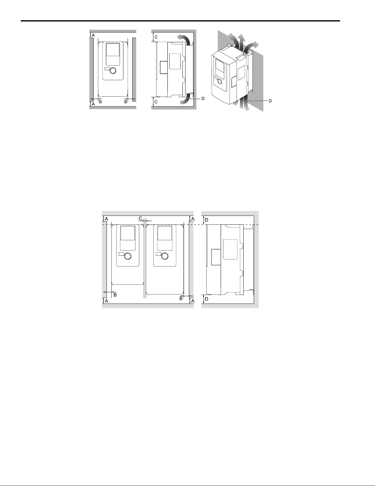
6 Mechanical Installation
A - 50 mm (2 in) minimum
B - 30 mm (1.2 in) minimum on both
sides
Figure 6.2 Installation Distances for One Drive
C - 120 mm (4.7 in) minimum above
and below
D - Airflow direction
■ Install Drives Side-by-Side
Users can install drive models 2004xB to 2082xB and 4002xB to 4044xB side-by-side.
To install other drive models adjacent to each other, you must keep 30 mm (1.2 in) between each drive.
For side-by-side installation of drive models 2004xB to 2082xB and 4002xB to 4044xB, make sure that there is
sufficient space as shown in Figure 6.3. Set L8-35 = 1 [Installation Method Selection = Side-by-Side Mounting].
Derate the output current to align with the ambient temperature.
A - 50 mm (2 in) minimum
B - 30 mm (1.2 in) minimum on both
sides
Figure 6.3 Installation Distances for Multiple Drives (Side-by-Side)
Note:
• Align the tops of drives that have different dimensions to help when you replace cooling fans.
• Remove the top protective covers of all drives when mounting UL Type 1 enclosure drives side-by-side.
16 YASKAWA TOEPC71061737B GA800 Drive Installation & Primary Operation
C - 2 mm (0.08 in) minimum between
each drive
D - 120 mm (4.7 in) minimum above
and below
Page 17
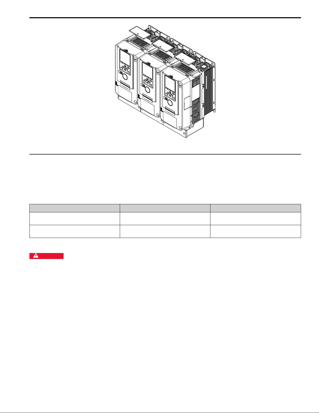
Figure 6.4 Enclosed Wall-Mounted Type (UL Type 1) Installed Side-by-Side
◆ Removing/Reattaching Covers
6 Mechanical Installation
This section gives information about how to remove and reattach the front cover and terminal cover for wiring and
inspection.
Different drive models have different procedures to remove and reattach the covers. Refer to Table 6.1 for more
information.
Table 6.1 Procedures to Remove Covers by Drive Model
Model Procedure Reference
2004 - 2211
4002 - 4168
2257 - 2415
4208 - 4720
Procedure A 17
Procedure B 19
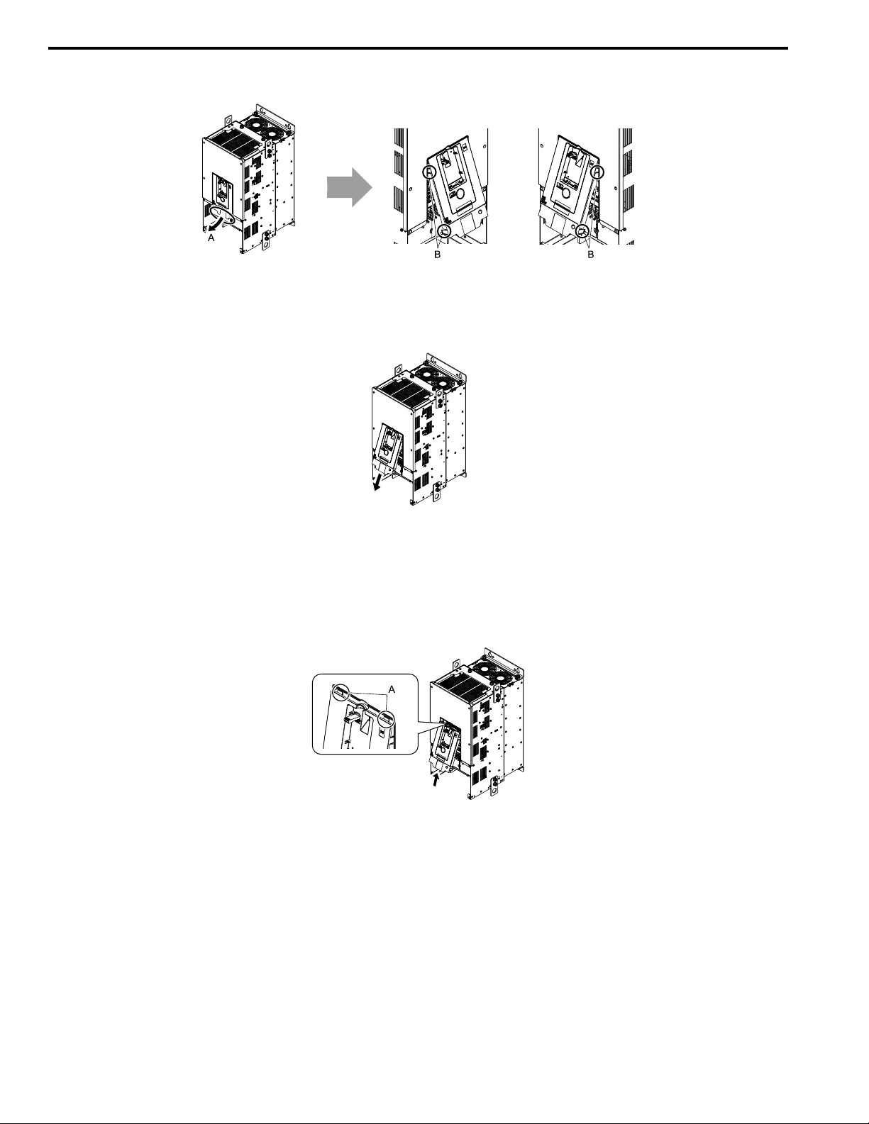
■ Removing/Reattaching the Cover Using Procedure A
DANGER
disconnect all power to the equipment and wait for the time specified on the warning label at a minimum. The internal capacitor
stays charged after the drive is de-energized. The charge indicator LED extinguishes when the DC bus voltage decreases below 50
Vdc. When all indicators are OFF, remove the covers before measuring for dangerous voltages to make sure that the drive is safe. If
you do work on the drive when it is energized, it will cause serious injury or death from electrical shock. The drive has internal
capacitors that stay charged after you de-energize the drive.
Electrical Shock Hazard. Do not examine, connect, or disconnect wiring on an energized drive. Before servicing,
YASKAWA TOEPC71061737B GA800 Drive Installation & Primary Operation 17
Page 18
6 Mechanical Installation
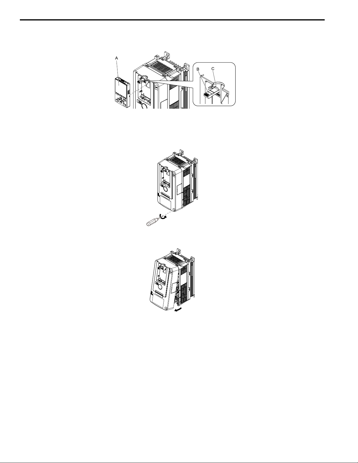
Remove the Front Cover
1. Remove the keypad and the keypad connector, then insert the end of the keypad connector that has the tab
into the keypad connector holder on the front cover.
A - Keypad
B - Keypad connector
Figure 6.5 Remove the Keypad and Keypad Connector
C - Holder
2. Loosen the front cover screws.
Figure 6.6 Loosen the Front Cover Screws
3. Push on the tab in the side of the front cover then pull the front cover forward to remove it from the drive.
Figure 6.7 Remove the Front Cover
Reattach the Front Cover
1. Wire the drive and other peripheral devices.
2. Reverse the steps to reattach the cover.
Note:
• Wire the grounding terminals first, main circuit terminals next, and control circuit terminals last.
• Make sure that you do not pinch wires or signal lines between the front cover and the drive before you reattach the cover.
• Tighten the screws to a tightening torque of 0.98 N∙m to 1.33 N∙m (8.67 in∙lb to 11.77 in∙lb).
18 YASKAWA TOEPC71061737B GA800 Drive Installation & Primary Operation
Page 19
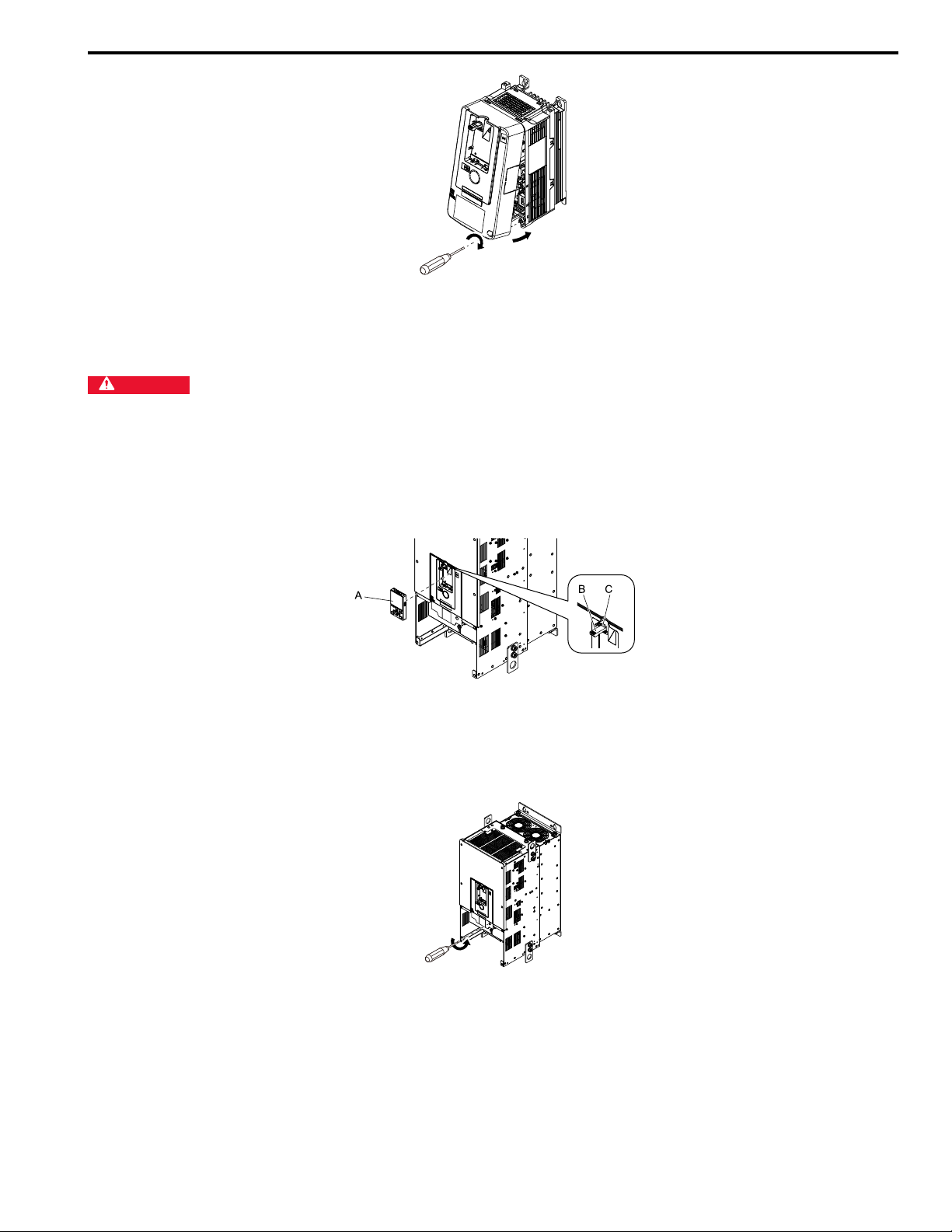
Figure 6.8 Reattach the Front Cover
3. Reattach the keypad to the original position.
■ Removing/Reattaching the Cover Using Procedure B
6 Mechanical Installation
DANGER
disconnect all power to the equipment and wait for the time specified on the warning label at a minimum. The internal capacitor
stays charged after the drive is de-energized. The charge indicator LED extinguishes when the DC bus voltage decreases below 50
Vdc. When all indicators are OFF, remove the covers before measuring for dangerous voltages to make sure that the drive is safe. If
you do work on the drive when it is energized, it will cause serious injury or death from electrical shock. The drive has internal
capacitors that stay charged after you de-energize the drive.
Electrical Shock Hazard. Do not examine, connect, or disconnect wiring on an energized drive. Before servicing,
Remove the Front Cover
1. Remove the terminal cover, keypad, and keypad connector, then insert the end of the keypad connector that
has the tab into the keypad connector holder on the front cover.
A - Keypad
B - Keypad connector
Figure 6.9 Remove the Terminal Cover, Keypad, and Keypad Connector
C - Connector holder
2. Loosen the front cover screws.
Figure 6.10 Loosen the Front Cover Screws
YASKAWA TOEPC71061737B GA800 Drive Installation & Primary Operation 19
Page 20
6 Mechanical Installation
3. Push on the four tabs found on each side of the front cover, then pull the front cover forward to remove it from
the drive.
A - Pull forward to remove the front
cover.
Figure 6.11 Pull Forward to Remove the Front Cover
B - Unhook the tabs found on the sides
of the front cover.
4. Remove the front cover from the drive.
Figure 6.12 Remove the Front Cover
Reattach the Front Cover
Wire the drive and other peripheral devices then reattach the front cover.
Note:
Wire the grounding terminals first, main circuit terminals next, and control circuit terminals last.
1. Move the front cover to connect the hooks at the top of the front cover to the drive.
A - Hooks
Figure 6.13 Reattach the Front Cover
2. Move the front cover until it clicks into position while pushing on the hooks on the left and right sides of the
front cover.
Note:
Make sure that you do not pinch wires or signal lines between the front cover and the drive before you reattach the cover.
20 YASKAWA TOEPC71061737B GA800 Drive Installation & Primary Operation
Page 21
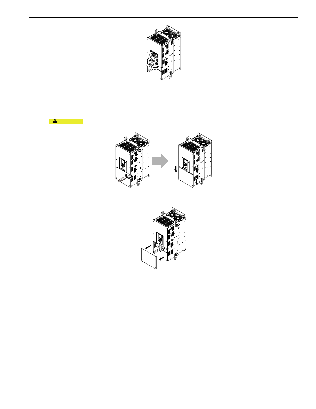
Figure 6.14 Reattach the Front Cover
3. Reattach the keypad to the original position.
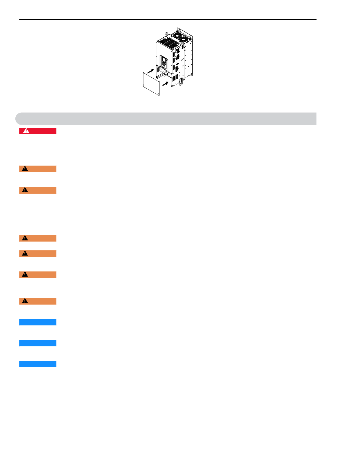
Remove the Terminal Cover
1. Loosen the screws on the terminal cover, then pull down on the cover.
6 Mechanical Installation
CAUTION
the terminal cover can fall and cause moderate injury.
Crush Hazard. Loosen the cover screws. Do not fully remove them. If you fully remove the cover screws,
Figure 6.15 Loosen the Terminal Cover Mounting Screws
2. Pull the terminal cover away from the drive.
Figure 6.16 Remove the Terminal Cover
Reattach the Terminal Cover
Wire the drive and other peripheral devices then reattach the terminal cover.
Note:
• Wire the grounding terminals first, main circuit terminals next, and control circuit terminals last.
• Make sure that you do not pinch wires or signal lines between the wiring cover and the drive before you reattach the cover.
• Tighten the screws to a tightening torque of 0.98 N∙m to 1.33 N∙m (8.67 in∙lb to 11.77 in∙lb).
YASKAWA TOEPC71061737B GA800 Drive Installation & Primary Operation 21
Page 22
7 Electrical Installation
Figure 6.17 Reattach the Terminal Cover
7 Electrical Installation
DANGER
disconnect all power to the equipment and wait for the time specified on the warning label at a minimum. The internal capacitor
stays charged after the drive is de-energized. The charge indicator LED extinguishes when the DC bus voltage decreases below 50
Vdc. When all indicators are OFF, remove the covers before measuring for dangerous voltages to make sure that the drive is safe. If
you do work on the drive when it is energized, it will cause serious injury or death from electrical shock. The drive has internal
capacitors that stay charged after you de-energize the drive.
WARNING
you energize the drive. Use terminals for their correct function only. Incorrect wiring connections and incorrect cover installation can
cause serious injury or death.
WARNING
manual for more information about the I/O terminals. Wiring and grounding incorrectly or modifying the cover may damage the
equipment or cause injury.
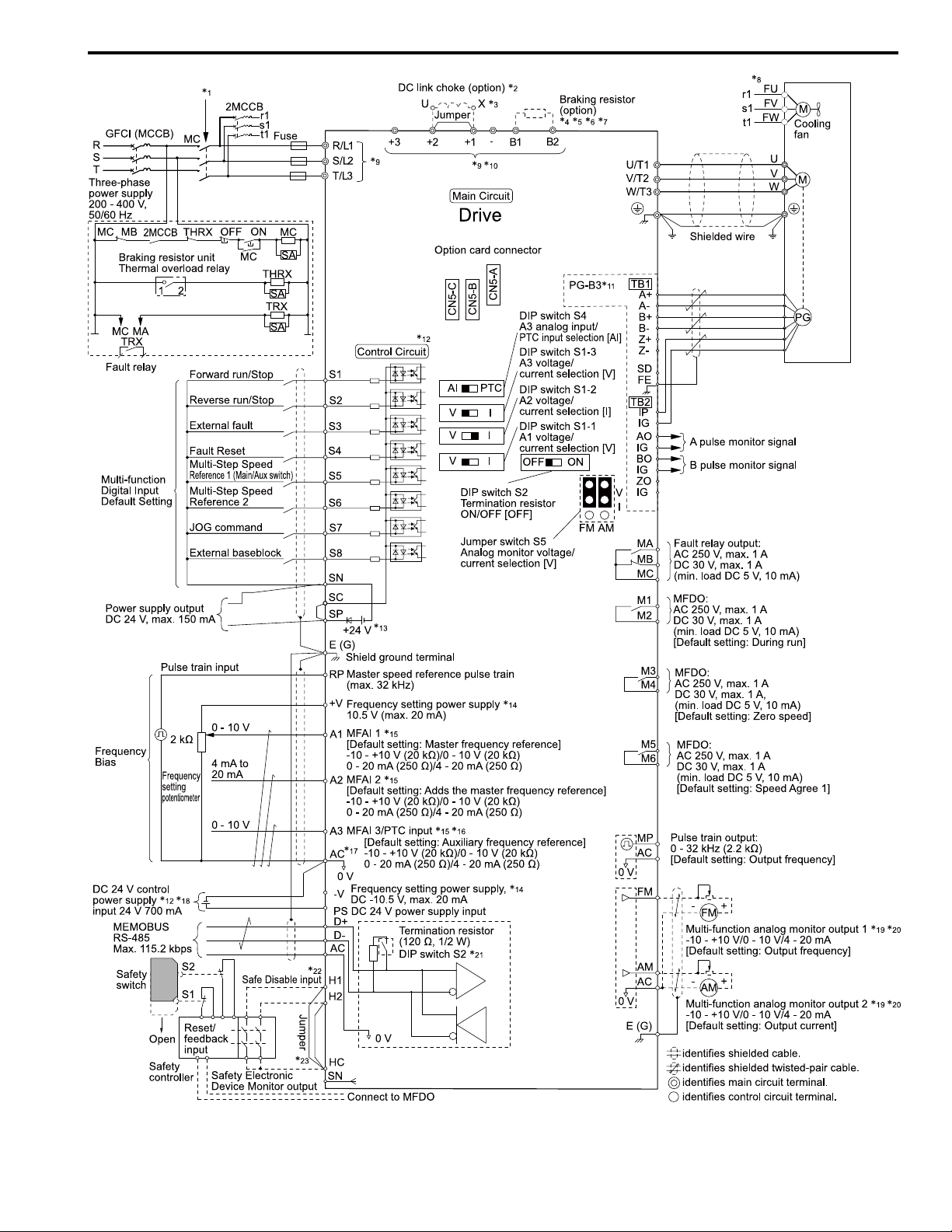
Standard Connection Diagram
Electrical Shock Hazard. Do not examine, connect, or disconnect wiring on an energized drive. Before servicing,
Electrical Shock Hazard. Make sure that all electrical connections are correct and install all drive covers before
Electrical Shock Hazard. Use the terminals for the drive only for their intended purpose. Refer to the technical
Wire the drive as specified by Figure 7.1.
WARNING
Stop circuit sequence settings can cause serious injury or death from moving equipment.
WARNING
momentarily close a digital input terminal, it can start a drive that is programmed for 3-Wire control and cause serious injury or death
from moving equipment.
WARNING
Initialization] and make sure that b1-17 = 0 [Run Command at Power Up = Disregard Existing RUN Command] (default). If you do
not correctly set the drive parameters for 3-Wire operation before you energize the drive, the motor can suddenly rotate in reverse
when you energize the drive.
WARNING
Application Preset function. When you set the Application Preset function
drive and it can cause equipment to operate unusually. This can cause serious injury or death.
NOTICE
manual. The drive is suited for circuits that supply not more than 100,000 RMS symmetrical amperes, 240 Vac maximum (200 V
Class), 480 Vac maximum (400 V Class). Incorrect branch circuit short circuit protection can cause serious injury or death.
NOTICE
motor insulation voltage is sufficient or use an inverter-duty motor or vector-duty motor with reinforced insulation. Motor winding and
insulation failure can occur.
NOTICE
circuit to operate incorrectly.
Sudden Movement Hazard. Set the MFDI parameters before you close control circuit switches. Incorrect Run/
Sudden Movement Hazard. Correctly wire the start/stop and safety circuits before you energize the drive. If you
Sudden Movement Hazard. When you use a 3-Wire sequence, set A1-03 = 3330 [Initialize Parameters = 3-Wire
Sudden Movement Hazard. Check the I/O signals and the external sequences for the drive before you set the
(A1-06 ≠ 0), it changes the I/O terminal functions for the
Fire Hazard. Install sufficient branch circuit short circuit protection as specified by applicable codes and this
When the input voltage is 440 V or higher or the wiring distance is longer than 100 m (328 ft), make sure that the
Do not connect the AC control circuit ground to the drive enclosure. Incorrect ground wiring can cause the control
22 YASKAWA TOEPC71061737B GA800 Drive Installation & Primary Operation
Page 23
7 Electrical Installation
Figure 7.1 Standard Drive Connection Diagram
YASKAWA TOEPC71061737B GA800 Drive Installation & Primary Operation 23
Page 24

7 Electrical Installation
*1 Set the wiring sequence to de-energize the drive with the fault relay output. If the drive outputs a fault during
fault restart when you use the fault restart function, set L5-02 = 1 [Fault Contact at Restart Select = Always
Active] to de-energize the drive. Be careful when you use a cut-off sequence. The default setting for L5-02 is 0
[Active Only when Not Restarting].
*2 When you install a DC link choke, you must remove the jumper between terminals +1 and +2.
*3 Models 2110 to 2415 and 4060 to 4720 have a DC link choke.
*4 When you use a regenerative converter, regenerative unit, or braking unit, set L8-55 = 0 [Internal DB
TransistorProtection = Disable]. If L8-55 = 1 [Protection Enabled], the drive will detect rF [Braking Resistor
Fault].
*5 When you use a regenerative converter, regenerative unit, braking unit, braking resistor, or braking resistor unit,
set L3-04 = 0 [Stall Prevention during Decel = Disabled] If L3-04 = 1 [General Purpose], the drive could
possibly not stop in the specified deceleration time.
*6 When you use an ERF-type braking resistor, set L8-01 = 1 [3% ERF DB Resistor Protection = Enabled] and set
a wiring sequence to de-energize the drive with the fault relay output.
*7 When you connect a braking unit (CDBR series) or a braking resistor unit (LKEB series) to drive models 2110,
2138, and 4103, make sure that you use wires that are in the range of the applicable gauges for the drive. A
junction terminal is necessary to connect wires that are less than the applicable gauge to the drive. Contact
Yaskawa or your nearest sales representative for more information about selection and installation of the junction
terminal.
*8 Cooling fan wiring is not necessary for self-cooling motors.
*9 Connect peripheral options to terminals -, +1, +2, B1, and B2.
WARNING
+3 terminals. Do not connect AC power to these terminals. Incorrect wiring can cause damage to the drive and serious injury
or death from fire.
Fire Hazard. Only connect factory-recommended devices or circuits to drive terminals B1, B2, -, +1, +2, and
*10 Encoder circuit wiring (wiring to PG-B3 option card) is not necessary for applications that do not use motor
speed feedback.
*11 Connect a 24 V power supply to terminals PS-AC to operate the control circuit while the main circuit power
supply is OFF.
*12 Install the wire jumpers between terminals SC-SP and SC-SN to set the MFDI power supply (sinking/sourcing
mode or internal/external power supply).
NOTICE
damage to the drive.
Do not close the circuit between terminals SP and SN. A closed circuit between these terminals will cause
• Sinking Mode: Install a jumper between terminals SC and SP.
NOTICE
damage to the drive.
Do not close the circuit between terminals SC and SN. A closed circuit between these terminals will cause
• Sourcing Mode: Install a jumper between terminals SC and SN.
NOTICE
damage to the drive.
Do not close the circuit between terminals SC and SP. A closed circuit between these terminals will cause
• External power supply: No jumper necessary between terminals SC-SN and terminals SC-SP.
*13 The maximum output current capacity for terminals +V and -V on the control circuit is 20 mA.
NOTICE
cause damage to the drive.
Do not install a jumper between terminals +V, -V, and AC. A closed circuit between these terminals will
*14 DIP switches S1-1 to S1-3 set terminals A1 to A3 for voltage or current input. The default setting for S1-1 and
S1-3 is voltage input (“V” side). The default setting for S1-2 is current input (“I” side).
*15 DIP switch S4 sets terminal A3 for analog or PTC input. Set DIP switch S1-3 to the “V” side, and set H3-05 = 0
[Terminal A3 Signal Level Select = 0 to 10V (Lower Limit at 0)] to set terminal A3 for PTC input with DIP
switch S4.
*16 Do not ground the control circuit terminals AC or connect them to the drive.
WARNING
instructions. If you connect the AC terminals incorrectly, it can cause damage to the drive.
Do not ground the AC control circuit terminals and only connect the AC terminals according to the product
*17 Connect the positive lead from an external 24 Vdc power supply to terminal PS and the negative lead to terminal
AC.
24 YASKAWA TOEPC71061737B GA800 Drive Installation & Primary Operation
Page 25
7 Electrical Installation
NOTICE
Connect terminals PS and AC correctly for the 24 V power supply. If you connect the wires to the incorrect
terminals, it will cause damage to the drive.
*18 Use multi-function analog monitor outputs with analog frequency meters, ammeters, voltmeters, and wattmeters.
Do not use monitor outputs with feedback-type signal devices.
*19 Jumper switch S5 sets terminal FM and AM for voltage or current output. The default setting for S5 is voltage
output (“V” side).
*20 Set DIP switch S2 to “ON” to enable the termination resistor in the last drive in a MEMOBUS/Modbus network.
*21 Use only SOURCE Mode for Safe Disable input.
*22 Disconnect the jumpers between H1 and HC and H2 and HC to use the Safe Disable input.
◆ Main Circuit Terminal Functions
Refer to Table 7.1 for the functions of drive main circuit terminals.
Table 7.1 Main Circuit Terminal Functions
Terminals Name
Model
R/L1
S/L2
T/L3
U/T1
W/T3
B1
B2
+2
+1
-
+3 -
2004 - 2082 2110 - 2138 2169 - 2415 -
4002 - 4044 4060 - 4168 4208 - 4414 4477 - 4720
Main circuit power supply input
Drive output To connect a motor.V/T2
Braking resistor connection -
• DC power supply input
(+1 and -)
• DC reactor connection
(+1 and +2)
• 200 V: D class grounding (ground to 100 Ω or less)
• 400 V: C class grounding (ground to 10 Ω or less)
DC power supply input (+1
and -)
• DC power supply input (+1 and -)
• Braking unit connection (+3 and -)
-
Note:
Use terminals B1 and - to connect a CDBR-type control unit to drive models 2004 to 2138 and 4002 to 4168 that have built-in braking
transistors.
Function
To connect a commercial
power supply.
To connect a braking resistor
or braking resistor unit.
To connect peripheral
devices, for example:
• DC power input
• Braking unit
• DC link choke
Note:
Remove the jumper
between terminals +1
and +2 to connect a DC
link choke.
To ground the drive.
◆ Motor and Main Circuit Connections
WARNING
the ground terminal. If you connect these terminals to earth ground, it can cause damage to the drive or serious injury or death.
YASKAWA TOEPC71061737B GA800 Drive Installation & Primary Operation 25
Electrical Shock Hazard. Do not connect terminals R/L1, S/L2, T/L3, U/T1, V/T2, W/T3, -, +1, +2, +3, B1, or B2 to
Page 26
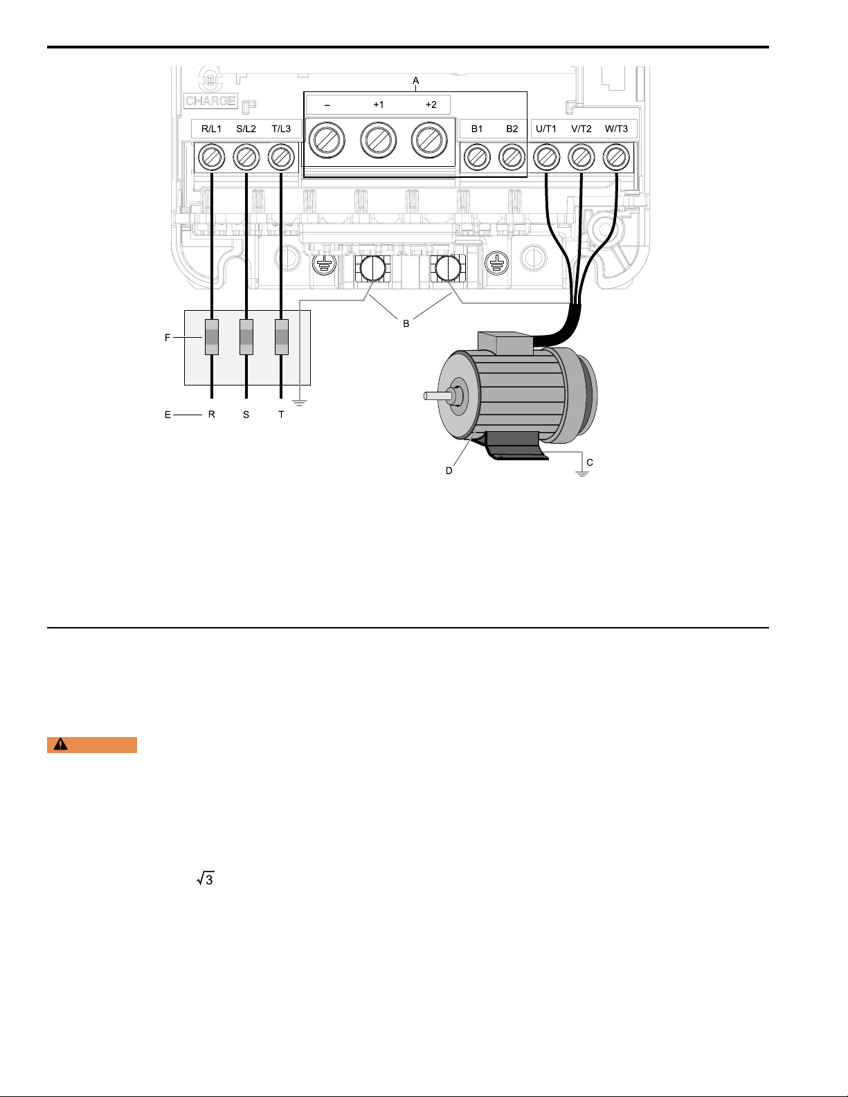
7 Electrical Installation
A - DC bus terminal
B - Connect to the drive ground
terminal.
C - Ground the motor case.
Note:
The location of terminals are different for different drive models.
Figure 7.2 Wiring the Main Circuit and Motor
D - Three-Phase Motor
E - Use R, S, T for input power supply.
F - Input Protection (Fuses or Circuit
Breakers)
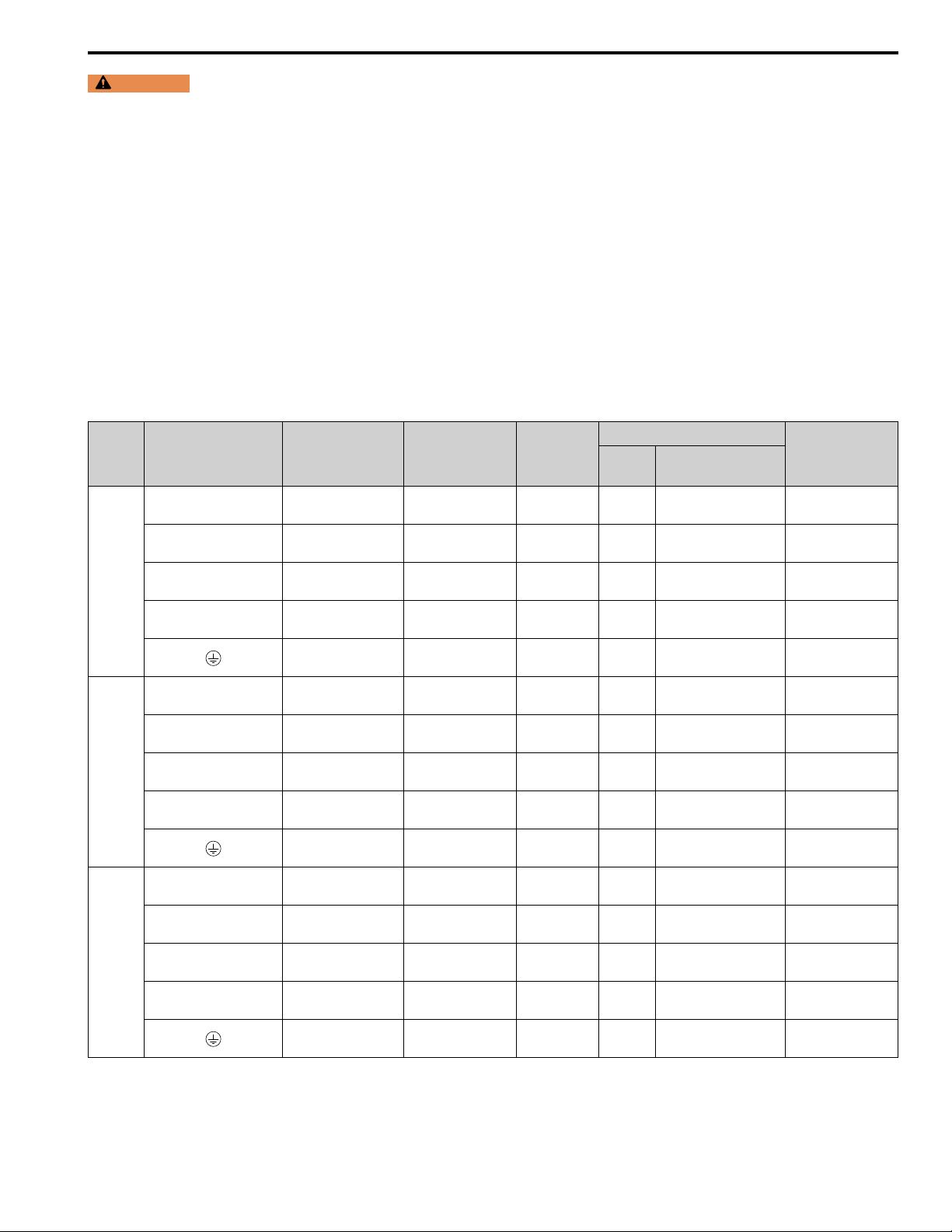
◆ Main Circuit Terminal Block Wiring
■ Wire Selection
Use this section to select the correct wires for main circuit wiring.
Wire Selection Precautions
WARNING
safety regulations. The IEC/EN 61800-5-1:2007 standard specifies that you must wire the power supply to automatically deenergize when the protective ground wire disconnects. You can also connect a protective ground wire that has a minimum crosssectional area of 10 mm
serious injury or death. The leakage current of the drive will be more than 3.5 mA in drive models 4414 to 4720.
Think about line voltage drop before selecting wire gauges. Select wire gauges that drop the voltage by 2% or less of
the rated voltage. Increase the wire gauge and the cable length when the risk of voltage drops increases. Calculate line
voltage drop with this formula:
Line voltage drop (V) = × wire resistance (Ω/km) × wiring distance (m) × motor rated current (A) × 10
Electrical Shock Hazard. Make sure that the protective ground wire conforms to technical standards and local
2
(copper wire) or 16 mm2(aluminum wire). If you do not obey the standards and regulations, it can cause
-3
.
Precautions during Wiring
• Use terminals B1 and - to connect braking units to drives that have built-in braking transistors (models 2004 to
2138 and 4002 to 4168). Use terminals +3 and - to connect braking units to drives that do not have built-in braking
transistors.
• Refer to “Yaskawa AC Drive Option Braking Unit, Braking Resistor Unit Instruction Manual (TOBPC72060001)”
for information about wire gauges and tightening torques to connect braking resistor units or braking units.
• Use terminals +1 and - to connect a regenerative converter or regenerative unit.
26 YASKAWA TOEPC71061737B GA800 Drive Installation & Primary Operation
Page 27
7 Electrical Installation
WARNING
Fire Hazard. Do not connect a braking resistor to terminals +1 or -. Use terminals B1 and B2 for the braking
resistor connections. If you connect a braking resistor to the incorrect terminals, it can cause damage to the drive and braking circuit
and serious injury or death.
Wire Gauge and Torque Specifications for UL Listing
Refer to Three-Phase 200 V Class on page 27 and Three-Phase 400 V Class on page 31 for the recommended wire
gauges and tightening torques of the main circuit terminals.
Note:
• The recommended wire gauges are based on drive continuous current ratings with 75 °C (167 °F) 600 V class 2 heat-resistant indoor PVC
wire. Assume these conditions:
–Ambient temperature: 40 °C (104 °F) or lower
–Wiring distance: 100 m (328 ft) or shorter
–Normal Duty Rated current value
• Use terminals +1, +2, +3, -, B1, and B2 to connect a peripheral option such as a DC link choke or a braking resistor. Do not connect other
items to these terminals.
• Refer to the instruction manual for each device for recommended wire gauges to connect peripheral devices or options to terminals +1, +2,
+3, -, B1, and B2. Contact Yaskawa or your nearest sales representative if the recommended wire gauges for the peripheral devices or
options are out of the range of the applicable gauges for the drive.
Three-Phase 200 V Class
Model Terminals
R/L1, S/L2, T/L3 14
U/T1, V/T2, W/T3 14
2004
2006
2008
-, +1, +2 14
B1, B2 14
R/L1, S/L2, T/L3 14
U/T1, V/T2, W/T3 14
-, +1, +2 14
B1, B2 14
R/L1, S/L2, T/L3 14
U/T1, V/T2, W/T3 14
-, +1, +2 14
B1, B2 14
Recommended
Gauge
AWG, kcmil
10
10
10
Applicable Gauge
(IP20 Applicable
Gauge*1)
AWG, kcmil
14 - 6
(14 - 6)
14 - 6
(14 - 6)
14 - 3
(14 - 3)
14 - 10
(14 - 10)
14 - 8
(-)
14 - 6
(14 - 6)
14 - 6
(14 - 6)
14 - 3
(14 - 3)
14 - 10
(14 - 10)
14 - 8
(-)
14 - 6
(14 - 6)
14 - 6
(14 - 6)
14 - 3
(14 - 3)
14 - 10
(14 - 10)
14 - 8
(-)
Wire Stripping
*2
Length
mm
10 M4 Slotted (-)
10 M4 Slotted (-)
18 M5 Slotted (-)
10 M4 Slotted (-)
- M4 Phillips/slotted combo
10 M4 Slotted (-)
10 M4 Slotted (-)
18 M5 Slotted (-)
10 M4 Slotted (-)
- M4 Phillips/slotted combo
10 M4 Slotted (-)
10 M4 Slotted (-)
18 M5 Slotted (-)
10 M4 Slotted (-)
- M4 Phillips/slotted combo
Terminal Screw
Size Shape
Tightening Torque
N∙m (in∙lb)
1.5 - 1.7
(13.5 - 15)
1.5 - 1.7
(13.5 - 15)
2.3 - 2.5
(19.8 - 22)
(19.8 - 22)
(19.8 - 22)
*3
1.5 - 1.7
(13.5 - 15)
1.2 - 1.5
(10.6 - 13.3)
1.5 - 1.7
(13.5 - 15)
1.5 - 1.7
(13.5 - 15)
2.3 - 2.5
*3
1.5 - 1.7
(13.5 - 15)
1.2 - 1.5
(10.6 - 13.3)
1.5 - 1.7
(13.5 - 15)
1.5 - 1.7
(13.5 - 15)
2.3 - 2.5
*3
1.5 - 1.7
(13.5 - 15)
1.2 - 1.5
(10.6 - 13.3)
YASKAWA TOEPC71061737B GA800 Drive Installation & Primary Operation 27
Page 28

7 Electrical Installation
Model Terminals
R/L1, S/L2, T/L3 12
U/T1, V/T2, W/T3 14
2010
2012
2018
2021
2030
-, +1, +2 12
B1, B2 14
R/L1, S/L2, T/L3 10
U/T1, V/T2, W/T3 12
-, +1, +2 10
B1, B2 14
R/L1, S/L2, T/L3 10
U/T1, V/T2, W/T3 10
-, +1, +2 8
B1, B2 14
R/L1, S/L2, T/L3 8
U/T1, V/T2, W/T3 10
-, +1, +2 8
B1, B2 14
R/L1, S/L2, T/L3 6
U/T1, V/T2, W/T3 8
-, +1, +2 6
B1, B2 12
Recommended
Gauge
AWG, kcmil
10
10
10
10
8
Applicable Gauge
(IP20 Applicable
Gauge*1)
AWG, kcmil
14 - 6
(14 - 6)
14 - 6
(14 - 6)
14 - 3
(14 - 3)
14 - 10
(14 - 10)
14 - 8
(-)
14 - 6
(14 - 6)
14 - 6
(14 - 6)
14 - 3
(14 - 3)
14 - 10
(14 - 10)
14 - 8
(-)
14 - 6
(14 - 6)
14 - 6
(14 - 6)
14 - 3
(14 - 3)
14 - 10
(14 - 10)
14 - 8
(-)
14 - 6
(14 - 6)
14 - 6
(14 - 6)
14 - 3
(14 - 3)
14 - 10
(14 - 10)
12 - 8
(-)
14 - 6
(14 - 6)
14 - 6
(14 - 6)
14 - 3
(14 - 3)
14 - 10
(14 - 10)
10 - 8
(-)
Wire Stripping
*2
Length
mm
10 M4 Slotted (-)
10 M4 Slotted (-)
18 M5 Slotted (-)
10 M4 Slotted (-)
- M4 Phillips/slotted combo
10 M4 Slotted (-)
10 M4 Slotted (-)
18 M5 Slotted (-)
10 M4 Slotted (-)
- M4 Phillips/slotted combo
10 M4 Slotted (-)
10 M4 Slotted (-)
18 M5 Slotted (-)
10 M4 Slotted (-)
- M4 Phillips/slotted combo
10 M4 Slotted (-)
10 M4 Slotted (-)
18 M5 Slotted (-)
10 M4 Slotted (-)
- M4 Phillips/slotted combo
10 M4 Slotted (-)
10 M4 Slotted (-)
18 M5 Slotted (-)
10 M4 Slotted (-)
- M5 Phillips/slotted combo
Terminal Screw
Size Shape
Tightening Torque
N∙m (in∙lb)
1.5 - 1.7
(13.5 - 15)
1.5 - 1.7
(13.5 - 15)
2.3 - 2.5
(19.8 - 22)
(19.8 - 22)
(19.8 - 22)
(19.8 - 22)
(19.8 - 22)
*3
1.5 - 1.7
(13.5 - 15)
1.2 - 1.5
(10.6 - 13.3)
1.5 - 1.7
(13.5 - 15)
1.5 - 1.7
(13.5 - 15)
2.3 - 2.5
*3
1.5 - 1.7
(13.5 - 15)
1.2 - 1.5
(10.6 - 13.3)
1.5 - 1.7
(13.5 - 15)
1.5 - 1.7
(13.5 - 15)
2.3 - 2.5
*3
1.5 - 1.7
(13.5 - 15)
1.2 - 1.5
(10.6 - 13.3)
1.5 - 1.7
(13.5 - 15)
1.5 - 1.7
(13.5 - 15)
2.3 - 2.5
*3
1.5 - 1.7
(13.5 - 15)
1.2 - 1.5
(10.6 - 13.3)
1.5 - 1.7
(13.5 - 15)
1.5 - 1.7
(13.5 - 15)
2.3 - 2.5
*3
1.5 - 1.7
(13.5 - 15)
2.0 - 2.5
(17.7 - 22.1)
28 YASKAWA TOEPC71061737B GA800 Drive Installation & Primary Operation
Page 29

7 Electrical Installation
Model Terminals
R/L1, S/L2, T/L3 6
U/T1, V/T2, W/T3 6
2042
2056
2070
2082
2110
-, +1, +2 3
B1, B2 10
R/L1, S/L2, T/L3 3
U/T1, V/T2, W/T3 4
-, +1, +2 1
B1, B2 8
R/L1, S/L2, T/L3 1
U/T1, V/T2, W/T3 3
-, +1, +2 1/0
B1, B2 8
R/L1, S/L2, T/L3 1/0
U/T1, V/T2, W/T3 2
-, +1, +2 2/0
B1, B2 6
R/L1, S/L2, T/L3 1/0
U/T1, V/T2, W/T3 1/0
-, +1 2/0
B1, B2 4
Recommended
Gauge
AWG, kcmil
8
6
6
6
6
Applicable Gauge
(IP20 Applicable
Gauge*1)
AWG, kcmil
14 - 6
(14 - 6)
14 - 6
(14 - 6)
14 - 3
(14 - 3)
14 - 10
(14 - 10)
10 - 8
(-)
14 - 3
(8 - 3)
14 - 4
(10 - 4)
14 - 1
(8 - 1)
14 - 8
(14 - 8)
8 - 6
(-)
14 - 1
(6 - 1)
14 - 3
(6 - 3)
14 - 1/0
(4 - 1/0)
14 - 8
(14 - 8)
6 - 4
(-)
14 - 1/0
(6 - 1/0)
14 - 2
(6 - 2)
14 - 2/0
(4 - 2/0)
14 - 6
(14 - 6)
6 - 4
(-)
6 - 1/0
(6 - 1/0)
6 - 1/0
(6 - 1/0)
2 - 2/0
(2 - 2/0)
14 - 4
(10 - 4)
6 - 4
(-)
Wire Stripping
*2
Length
mm
10 M4 Slotted (-)
10 M4 Slotted (-)
18 M5 Slotted (-)
10 M4 Slotted (-)
- M5 Phillips/slotted combo
18 M5 Slotted (-)
18 M5 Slotted (-)
20 M6
10 M4 Slotted (-)
- M6 Phillips/slotted combo
20 M6
20 M6
20 M6
10 M4 Slotted (-)
- M6 Phillips/slotted combo
20 M6
20 M6
20 M6
10 M4 Slotted (-)
- M6 Phillips/slotted combo
27 M6
27 M6
27 M8
21 M6 Slotted (-)
- M6 Hex bolt (+)
Terminal Screw
Size Shape
Hex socket cap
(WAF: 5 mm)
Hex socket cap
(WAF: 5 mm)
Hex socket cap
(WAF: 5 mm)
Hex socket cap
(WAF: 5 mm)
Hex socket cap
(WAF: 5 mm)
Hex socket cap
(WAF: 5 mm)
Hex socket cap
(WAF: 5 mm)
Hex socket cap
(WAF: 5 mm)
Hex socket cap
(WAF: 5 mm)
Hex socket cap
(WAF: 6 mm)
Tightening Torque
N∙m (in∙lb)
1.5 - 1.7
(13.5 - 15)
1.5 - 1.7
(13.5 - 15)
2.3 - 2.5
(19.8 - 22)
(19.8 - 22)
(19.8 - 22)
*3
1.5 - 1.7
(13.5 - 15)
2.0 - 2.5
(17.7 - 22.1)
2.3 - 2.5
*3
2.3 - 2.5
*3
5 - 5.5
(45 - 49)
1.5 - 1.7
(13.5 - 15)
5.4 - 6.0
(47.8 - 53.1)
5 - 5.5
(45 - 49)
5 - 5.5
(45 - 49)
5 - 5.5
(45 - 49)
1.5 - 1.7
(13.5 - 15)
5.4 - 6.0
(47.8 - 53.1)
5 - 5.5
(45 - 49)
5 - 5.5
(45 - 49)
5 - 5.5
(45 - 49)
1.5 - 1.7
(13.5 - 15)
5.4 - 6.0
(47.8 - 53.1)
8 - 9
(71 - 80)
8 - 9
(71 - 80)
10 - 12
(89 - 107)
3 - 3.5
(27 - 31)
5.4 - 6.0
(47.8 - 53.1)
YASKAWA TOEPC71061737B GA800 Drive Installation & Primary Operation 29
Page 30

7 Electrical Installation
Model Terminals
R/L1, S/L2, T/L3 2/0
U/T1, V/T2, W/T3 2/0
2138
2169
2211
2257
2313
-, +1 4/0
B1, B2 3
R/L1, S/L2, T/L3 4/0
U/T1, V/T2, W/T3 4/0
-, -, +1, +1
R/L1, S/L2, T/L3 250
U/T1, V/T2, W/T3 300
-, -, +1, +1
R/L1, S/L2, T/L3 2/0 × 2P
U/T1, V/T2, W/T3 2/0 × 2P
R/L1, S/L2, T/L3 4/0 × 2P
U/T1, V/T2, W/T3 3/0 × 2P
*4 *5
*5
+3
*4 *5
*5
+3
-, +1 4/0 × 2P
+3 1/0 × 2P
-, +1 250 × 2P
+3 1/0 × 2P
Recommended
Gauge
AWG, kcmil
4
1
1/0
4
2/0
2/0
4
3
2
Applicable Gauge
(IP20 Applicable
Gauge*1)
AWG, kcmil
6 - 2/0
(2 - 2/0)
6 - 2/0
(2 - 2/0)
2 - 4/0
(2 - 4/0)
14 - 3
(10 - 3)
4
(-)
2 - 250
(2/0 - 250)
2 - 300
(3/0 - 300)
6 - 2/0
(1/0 - 2/0)
4 - 2/0
(1 - 2/0)
4 - 1/0
(-)
2 - 250
(2/0 - 250)
2 - 300
(3/0 - 300)
6 - 2/0
(1/0 - 2/0)
4 - 2/0
(1 - 2/0)
4 - 1/0
(-)
3 - 4/0 × 2P
(2/0 - 4/0 × 2P)
3 - 4/0 × 2P
(2/0 - 4/0 × 2P)
2 - 250 × 2P
(4/0 - 250 × 2P)
4 - 1/0 × 2P
(1/0 × 2P)
3 - 350
(-)
3 - 4/0 × 2P
(2/0 - 4/0 × 2P)
3 - 4/0 × 2P
(2/0 - 4/0 × 2P)
2 - 250 × 2P
(4/0 - 250 × 2P)
4 - 1/0 × 2P
(1/0 × 2P)
2 - 350
(-)
Wire Stripping
*2
Length
mm
27 M6
27 M6
27 M8
21 M6 Slotted (-)
- M6 Hex bolt (+)
37 M10
37 M10
28 M6
28 M8
- M8 Hex bolt (slotted)
37 M10
37 M10
28 M6
28 M8
- M8 Hex bolt (slotted)
- M10 Hex self-locking nut
- M10 Hex self-locking nut
- M10 Hex self-locking nut
- M10 Hex self-locking nut
- M10 Hex bolt (slotted)
- M10 Hex self-locking nut
- M10 Hex self-locking nut
- M10 Hex self-locking nut
- M10 Hex self-locking nut
- M10 Hex bolt (slotted)
Terminal Screw
Size Shape
Hex socket cap
(WAF: 5 mm)
Hex socket cap
(WAF: 5 mm)
Hex socket cap
(WAF: 6 mm)
Hex socket cap
(WAF: 8 mm)
Hex socket cap
(WAF: 8 mm)
Hex socket cap
(WAF: 5 mm)
Hex socket cap
(WAF: 6 mm)
Hex socket cap
(WAF: 8 mm)
Hex socket cap
(WAF: 8 mm)
Hex socket cap
(WAF: 5 mm)
Hex socket cap
(WAF: 6 mm)
Tightening Torque
N∙m (in∙lb)
8 - 9
(71 - 80)
8 - 9
(71 - 80)
10 - 12
(89 - 107)
3 - 3.5
(27 - 31)
5.4 - 6.0
(47.8 - 53.1)
12 - 14
(107 - 124)
12 - 14
(107 - 124)
8 - 9
(71 - 80)
8 - 9
(71 - 80)
9.0 - 11
(79.7 - 97.4)
12 - 14
(107 - 124)
12 - 14
(107 - 124)
8 - 9
(71 - 80)
8 - 9
(71 - 80)
9.0 - 11
(79.7 - 97.4)
20
(177)
20
(177)
20
(177)
20
(177)
18 - 23
(159 - 204)
20
(177)
20
(177)
20
(177)
20
(177)
18 - 23
(159 - 204)
30 YASKAWA TOEPC71061737B GA800 Drive Installation & Primary Operation
Page 31

7 Electrical Installation
Model Terminals
R/L1, S/L2, T/L3 250 × 2P
U/T1, V/T2, W/T3 250 × 2P
2360
2415
-, +1 350 × 2P
+3 3/0 × 2P
R/L1, S/L2, T/L3 250 × 2P
U/T1, V/T2, W/T3 300 × 2P
-, +1 350 × 2P
+3 3/0 × 2P
Recommended
Gauge
AWG, kcmil
1
1
Applicable Gauge
(IP20 Applicable
Gauge*1)
AWG, kcmil
2/0 - 300 × 2P
(250 - 300 × 2P)
2/0 - 300 × 2P
(250 - 300 × 2P)
4/0 - 400 × 2P
(300 - 400 × 2P)
1/0 - 4/0 × 2P
(-)
1 - 350
(-)
2/0 - 300 × 2P
(250 - 300 × 2P)
2/0 - 300 × 2P
(250 - 300 × 2P)
4/0 - 400 × 2P
(300 - 400 × 2P)
1/0 - 4/0 × 2P
(-)
1 - 350
(-)
Wire Stripping
*2
Length
mm
- M12 Hex self-locking nut
- M12 Hex self-locking nut
- M12 Hex self-locking nut
- M12 Hex self-locking nut
- M12 Hex bolt (slotted)
- M12 Hex self-locking nut
- M12 Hex self-locking nut
- M12 Hex self-locking nut
- M12 Hex self-locking nut
- M12 Hex bolt (slotted)
Terminal Screw
Size Shape
*1 For IP20 protection, use wires that are in the range of applicable gauges.
*2 Remove insulation from the ends of wires to expose the length of wire shown.
*3 For wire gauges more than AWG 8, tighten to a tightening torque of 4.1 N∙m to 4.5 N∙m (36 in∙lb to 40 in∙lb).
*4 Terminals - and +1 have two screws. The Recommended Gauge is the wire gauge for one terminal.
*5 A junction terminal is necessary to connect a braking unit (CDBR-series) to terminals - and +3.
Three-Phase 400 V Class
Tightening Torque
N∙m (in∙lb)
35
(310)
35
(310)
35
(310)
35
(310)
32 - 40
(283 - 354)
35
(310)
35
(310)
35
(310)
35
(310)
32 - 40
(283 - 354)
Model Terminal
R/L1, S/L2, T/L3 14
U/T1, V/T2, W/T3 14
4002
4004
-, +1, +2 14
B1, B2 14
R/L1, S/L2, T/L3 14
U/T1, V/T2, W/T3 14
-, +1, +2 14
B1, B2 14
Recommended
Gauge
AWG, kcmil
12
12
Applicable Gauge
(IP20 Applicable
Gauge*1)
AWG, kcmil
14 - 6
(14 - 6)
14 - 6
(14 - 6)
14 - 3
(14 - 3)
14 - 10
(14 - 10)
14 - 8
(-)
14 - 6
(14 - 6)
14 - 6
(14 - 6)
14 - 3
(14 - 3)
14 - 10
(14 - 10)
14 - 8
(-)
Wire Stripping
*2
Length
mm
10 M4 Slotted (-)
10 M4 Slotted (-)
18 M5 Slotted (-)
10 M4 Slotted (-)
- M4 Phillips/slotted combo
10 M4 Slotted (-)
10 M4 Slotted (-)
18 M5 Slotted (-)
10 M4 Slotted (-)
- M4 Phillips/slotted combo
Terminal Screw
Size Shape
Tightening Torque
N∙m (in∙lb)
1.5 - 1.7
(13.5 - 15)
1.5 - 1.7
(13.5 - 15)
2.3 - 2.5
(19.8 - 22)
(19.8 - 22)
*3
1.5 - 1.7
(13.5 - 15)
1.2 - 1.5
(10.6 - 13.3)
1.5 - 1.7
(13.5 - 15)
1.5 - 1.7
(13.5 - 15)
2.3 - 2.5
*3
1.5 - 1.7
(13.5 - 15)
1.2 - 1.5
(10.6 - 13.3)
YASKAWA TOEPC71061737B GA800 Drive Installation & Primary Operation 31
Page 32

7 Electrical Installation
Model Terminal
R/L1, S/L2, T/L3 14
U/T1, V/T2, W/T3 14
4005
4007
4009
4012
4018
-, +1, +2 14
B1, B2 14
R/L1, S/L2, T/L3 14
U/T1, V/T2, W/T3 14
-, +1, +2 14
B1, B2 14
R/L1, S/L2, T/L3 14
U/T1, V/T2, W/T3 14
-, +1, +2 12
B1, B2 14
R/L1, S/L2, T/L3 12
U/T1, V/T2, W/T3 14
-, +1, +2 10
B1, B2 14
R/L1, S/L2, T/L3 10
U/T1, V/T2, W/T3 10
-, +1, +2 8
B1, B2 14
Recommended
Gauge
AWG, kcmil
10
10
10
10
10
Applicable Gauge
(IP20 Applicable
Gauge*1)
AWG, kcmil
14 - 6
(14 - 6)
14 - 6
(14 - 6)
14 - 3
(14 - 3)
14 - 10
(14 - 10)
14 - 8
(-)
14 - 6
(14 - 6)
14 - 6
(14 - 6)
14 - 3
(14 - 3)
14 - 10
(14 - 10)
14 - 8
(-)
14 - 6
(14 - 6)
14 - 6
(14 - 6)
14 - 3
(14 - 3)
14 - 10
(14 - 10)
14 - 8
(-)
14 - 6
(14 - 6)
14 - 6
(14 - 6)
14 - 3
(14 - 3)
14 - 10
(14 - 10)
14 - 8
(-)
14 - 6
(14 - 6)
14 - 6
(14 - 6)
14 - 3
(14 - 3)
14 - 10
(14 - 10)
14 - 8
(-)
Wire Stripping
*2
Length
mm
10 M4 Slotted (-)
10 M4 Slotted (-)
18 M5 Slotted (-)
10 M4 Slotted (-)
- M4 Phillips/slotted combo
10 M4 Slotted (-)
10 M4 Slotted (-)
18 M5 Slotted (-)
10 M4 Slotted (-)
- M4 Phillips/slotted combo
10 M4 Slotted (-)
10 M4 Slotted (-)
18 M5 Slotted (-)
10 M4 Slotted (-)
- M4 Phillips/slotted combo
10 M4 Slotted (-)
10 M4 Slotted (-)
18 M5 Slotted (-)
10 M4 Slotted (-)
- M4 Phillips/slotted combo
10 M4 Slotted (-)
10 M4 Slotted (-)
18 M5 Slotted (-)
10 M4 Slotted (-)
- M5 Phillips/slotted combo
Terminal Screw
Size Shape
Tightening Torque
N∙m (in∙lb)
1.5 - 1.7
(13.5 - 15)
1.5 - 1.7
(13.5 - 15)
2.3 - 2.5
(19.8 - 22)
(10.6 - 13.3)
(19.8 - 22)
(10.6 - 13.3)
(19.8 - 22)
(10.6 - 13.3)
(19.8 - 22)
(10.6 - 13.3)
(19.8 - 22)
(17.7 - 22.1)
*3
1.5 - 1.7
(13.5 - 15)
1.2 - 1.5
1.5 - 1.7
(13.5 - 15)
1.5 - 1.7
(13.5 - 15)
2.3 - 2.5
*3
1.5 - 1.7
(13.5 - 15)
1.2 - 1.5
1.5 - 1.7
(13.5 - 15)
1.5 - 1.7
(13.5 - 15)
2.3 - 2.5
*3
1.5 - 1.7
(13.5 - 15)
1.2 - 1.5
1.5 - 1.7
(13.5 - 15)
1.5 - 1.7
(13.5 - 15)
2.3 - 2.5
*3
1.5 - 1.7
(13.5 - 15)
1.2 - 1.5
1.5 - 1.7
(13.5 - 15)
1.5 - 1.7
(13.5 - 15)
2.3 - 2.5
*3
1.5 - 1.7
(13.5 - 15)
2.0 - 2.5
32 YASKAWA TOEPC71061737B GA800 Drive Installation & Primary Operation
Page 33

7 Electrical Installation
Model Terminal
R/L1, S/L2, T/L3 8
U/T1, V/T2, W/T3 10
4023
4031
4038
4044
4060
-, +1, +2 8
B1, B2 12
R/L1, S/L2, T/L3 6
U/T1, V/T2, W/T3 8
-, +1, +2 6
B1, B2 10
R/L1, S/L2, T/L3 6
U/T1, V/T2, W/T3 8
-, +1, +2 4
B1, B2 10
R/L1, S/L2, T/L3 4
U/T1, V/T2, W/T3 6
-, +1, +2 3
B1, B2 8
R/L1, S/L2, T/L3 4
U/T1, V/T2, W/T3 4
-, +1 3
B1, B2 8
Recommended
Gauge
AWG, kcmil
10
8
6
6
6
Applicable Gauge
(IP20 Applicable
Gauge*1)
AWG, kcmil
14 - 6
(14 - 6)
14 - 6
(14 - 6)
14 - 3
(14 - 3)
14 - 10
(14 - 10)
12 - 8
(-)
14 - 3
(8 - 3)
14 - 4
(10 - 4)
14 - 1
(8 - 1)
14 - 8
(14 - 8)
10 - 6
(-)
14 - 3
(8 - 3)
14 - 4
(10 - 4)
14 - 1
(8 - 1)
14 - 8
(14 - 8)
10 - 6
(-)
14 - 4
(10 - 4)
14 - 6
(10 - 6)
14 - 3
(10 - 3)
14 - 8
(14 - 8)
8 - 4
(-)
14 - 4
(10 - 4)
14 - 4
(10 - 4)
14 - 3
(10 - 3)
14 - 8
(14 - 8)
8 - 4
(-)
Wire Stripping
*2
Length
mm
10 M4 Slotted (-)
10 M4 Slotted (-)
18 M5 Slotted (-)
10 M4 Slotted (-)
- M5 Phillips/slotted combo
18 M5 Slotted (-)
18 M5 Slotted (-)
20 M6
10 M4 Slotted (-)
- M6 Phillips/slotted combo
18 M5 Slotted (-)
18 M5 Slotted (-)
20 M6
10 M4 Slotted (-)
- M6 Phillips/slotted combo
18 M5 Slotted (-)
18 M5 Slotted (-)
18 M5 Slotted (-)
10 M4 Slotted (-)
- M6 Phillips/slotted combo
18 M5 Slotted (-)
18 M5 Slotted (-)
18 M5 Slotted (-)
10 M4 Slotted (-)
- M6 Phillips/slotted combo
Terminal Screw
Size Shape
Hex socket cap
(WAF: 5 mm)
Hex socket cap
(WAF: 5 mm)
Tightening Torque
N∙m (in∙lb)
1.5 - 1.7
(13.5 - 15)
1.5 - 1.7
(13.5 - 15)
2.3 - 2.5
(19.8 - 22)
(19.8 - 22)
(19.8 - 22)
(19.8 - 22)
(19.8 - 22)
(19.8 - 22)
(19.8 - 22)
(19.8 - 22)
(19.8 - 22)
(19.8 - 22)
(19.8 - 22)
*3
1.5 - 1.7
(13.5 - 15)
2.0 - 2.5
(17.7 - 22.1)
2.3 - 2.5
*3
2.3 - 2.5
*3
5 - 5.5
(45 - 49)
1.5 - 1.7
(13.5 - 15)
5.4 - 6.0
(47.8 - 53.1)
2.3 - 2.5
*3
2.3 - 2.5
*3
5 - 5.5
(45 - 49)
1.5 - 1.7
(13.5 - 15)
5.4 - 6.0
(47.8 - 53.1)
2.3 - 2.5
*3
2.3 - 2.5
*3
2.3 - 2.5
*3
1.5 - 1.7
(13.5 - 15)
5.4 - 6.0
(47.8 - 53.1)
2.3 - 2.5
*3
2.3 - 2.5
*3
2.3 - 2.5
*3
1.5 - 1.7
(13.5 - 15)
5.4 - 6.0
(47.8 - 53.1)
YASKAWA TOEPC71061737B GA800 Drive Installation & Primary Operation 33
Page 34

7 Electrical Installation
Model Terminal
R/L1, S/L2, T/L3 3
U/T1, V/T2, W/T3 3
4075
4089
4103
4140
4168
-, +1 2
B1, B2 6
R/L1, S/L2, T/L3 2
U/T1, V/T2, W/T3 2
-, +1 1/0
B1, B2 6
R/L1, S/L2, T/L3 1/0
U/T1, V/T2, W/T3 1
-, +1 2/0
B1, B2 3
R/L1, S/L2, T/L3 3/0
U/T1, V/T2, W/T3 2/0
-, -, +1, +1
B1, B2
R/L1, S/L2, T/L3 4/0
U/T1, V/T2, W/T3 4/0
-, -, +1, +1
B1, B2
Recommended
Gauge
AWG, kcmil
6
4
4
*4
*5
*4
*5
2
1
4
1/0
1/0
4
Applicable Gauge
(IP20 Applicable
Gauge*1)
AWG, kcmil
14 - 3
(12 - 3)
14 - 3
(12 - 3)
14 - 2
(10 - 2)
14 - 6
(14 - 6)
6 - 4
(-)
14 - 2
(10 - 2)
14 - 2
(10 - 2)
14 - 1/0
(6 - 1/0)
14 - 6
(14 - 6)
6 - 4
(-)
6 - 2/0
(2 - 2/0)
6 - 2/0
(2 - 2/0)
2 - 4/0
(2 - 4/0)
14 - 3
(10 - 3)
6 - 4
(-)
2 - 250
(2/0 - 250)
2 - 300
(3/0 - 300)
6 - 2/0
(1/0 - 2/0)
4 - 2/0
(1 - 2/0)
4 - 1/0
(-)
2 - 250
(2/0 - 250)
2 - 300
(3/0 - 300)
6 - 2/0
(1/0 - 2/0)
4 - 2/0
(1 - 2/0)
4 - 1/0
(-)
Wire Stripping
*2
Length
mm
18 M5 Slotted (-)
18 M5 Slotted (-)
18 M5 Slotted (-)
10 M4 Slotted (-)
- M6 Hex bolt (+)
18 M5 Slotted (-)
18 M5 Slotted (-)
20 M6
18 M5 Slotted (-)
- M6 Hex bolt (+)
27 M6
27 M6
27 M8
21 M6 Slotted (-)
- M6 Hex bolt (+)
37 M10
37 M10
28 M6
28 M8
- M8 Hex bolt (slotted)
37 M10
37 M10
28 M6
28 M8
- M8 Hex bolt (slotted)
Terminal Screw
Size Shape
Hex socket cap
(WAF: 5 mm)
Hex socket cap
(WAF: 5 mm)
Hex socket cap
(WAF: 5 mm)
Hex socket cap
(WAF: 6 mm)
Hex socket cap
(WAF: 8 mm)
Hex socket cap
(WAF: 8 mm)
Hex socket cap
(WAF: 5 mm)
Hex socket cap
(WAF: 6 mm)
Hex socket cap
(WAF: 8 mm)
Hex socket cap
(WAF: 8 mm)
Hex socket cap
(WAF: 5 mm)
Hex socket cap
(WAF: 6 mm)
Tightening Torque
N∙m (in∙lb)
2.3 - 2.5
(19.8 - 22)
(19.8 - 22)
(19.8 - 22)
(47.8 - 53.1)
(19.8 - 22)
(19.8 - 22)
(19.8 - 22)
(47.8 - 53.1)
(47.8 - 53.1)
(79.7 - 97.4)
(79.7 - 97.4)
*3
2.3 - 2.5
*3
2.3 - 2.5
*3
1.5 - 1.7
(13.5 - 15)
5.4 - 6.0
2.3 - 2.5
*3
2.3 - 2.5
*3
5 - 5.5
(45 - 49)
2.3 - 2.5
*3
5.4 - 6.0
8 - 9
(71 - 80)
8 - 9
(71 - 80)
10 - 12
(89 - 107)
3 - 3.5
(27 - 31)
5.4 - 6.0
12 - 14
(107 - 124)
12 - 14
(107 - 124)
8 - 9
(71 - 80)
8 - 9
(71 - 80)
9.0 - 11
12 - 14
(107 - 124)
12 - 14
(107 - 124)
8 - 9
(71 - 80)
8 - 9
(71 - 80)
9.0 - 11
34 YASKAWA TOEPC71061737B GA800 Drive Installation & Primary Operation
Page 35

7 Electrical Installation
Model Terminal
R/L1, S/L2, T/L3 1/0 × 2P
U/T1, V/T2, W/T3 1/0 × 2P
4208
4250
4302
4371
4414
-, +1 3/0 × 2P
+3 1/0 × 2P
R/L1, S/L2, T/L3 2/0 × 2P
U/T1, V/T2, W/T3 2/0 × 2P
-, +1 3/0 × 2P
+3 1/0 × 2P
R/L1, S/L2, T/L3 3/0 × 2P
U/T1, V/T2, W/T3 3/0 × 2P
-, +1 4/0 × 2P
+3 1/0 × 2P
R/L1, S/L2, T/L3 250 × 2P
U/T1, V/T2, W/T3 250 × 2P
-, +1 350 × 2P
+3 3/0 × 2P
R/L1, S/L2, T/L3 300 × 2P
U/T1, V/T2, W/T3 300 × 2P
-, +1 400 × 2P
+3 4/0 × 2P
Recommended
Gauge
AWG, kcmil
4
2
2
1
1
Applicable Gauge
(IP20 Applicable
Gauge*1)
AWG, kcmil
3 - 4/0 × 2P
(2/0 - 4/0 × 2P)
3 - 4/0 × 2P
(2/0 - 4/0 × 2P)
2 - 250 × 2P
(4/0 - 250 × 2P)
4 - 1/0 × 2P
(1/0 × 2P)
4 - 350
(-)
3 - 4/0 × 2P
(2/0 - 4/0 × 2P)
3 - 4/0 × 2P
(2/0 - 4/0 × 2P)
2 - 250 × 2P
(4/0 - 250 × 2P)
4 - 1/0 × 2P
(1/0 × 2P)
2 - 350
(-)
3 - 4/0 × 2P
(2/0 - 4/0 × 2P)
3 - 4/0 × 2P
(2/0 - 4/0 × 2P)
2 - 250 × 2P
(4/0 - 250 × 2P)
4 - 1/0 × 2P
(1/0 × 2P)
2 - 350
(-)
2/0 - 300 × 2P
(250 - 300 × 2P)
2/0 - 300 × 2P
(250 - 300 × 2P)
4/0 - 400 × 2P
(300 - 400 × 2P)
1 - 4/0 × 2P
(-)
1 - 350
(-)
2/0 - 300 × 2P
(250 - 300 × 2P)
2/0 - 300 × 2P
(250 - 300 × 2P)
4/0 - 400 × 2P
(300 - 400 × 2P)
1 - 4/0 × 2P
(-)
1 - 350
(-)
Wire Stripping
*2
Length
mm
- M10 Hex self-locking nut
- M10 Hex self-locking nut
- M10 Hex self-locking nut
- M10 Hex self-locking nut
- M10 Hex bolt (slotted)
- M10 Hex self-locking nut
- M10 Hex self-locking nut
- M10 Hex self-locking nut
- M10 Hex self-locking nut
- M10 Hex bolt (slotted)
- M10 Hex self-locking nut
- M10 Hex self-locking nut
- M10 Hex self-locking nut
- M10 Hex self-locking nut
- M10 Hex bolt (slotted)
- M12 Hex self-locking nut
- M12 Hex self-locking nut
- M12 Hex self-locking nut
- M12 Hex self-locking nut
- M12 Hex bolt (slotted)
- M12 Hex self-locking nut
- M12 Hex self-locking nut
- M12 Hex self-locking nut
- M12 Hex self-locking nut
- M12 Hex bolt (slotted)
Terminal Screw
Size Shape
Tightening Torque
N∙m (in∙lb)
20
(177)
20
(177)
20
(177)
20
(177)
18 - 23
(159 - 204)
20
(177)
20
(177)
20
(177)
20
(177)
18 - 23
(159 - 204)
20
(177)
20
(177)
20
(177)
20
(177)
18 - 23
(159 - 204)
35
(310)
35
(310)
35
(310)
35
(310)
32 - 40
(283 - 354)
35
(310)
35
(310)
35
(310)
35
(310)
32 - 40
(283 - 354)
YASKAWA TOEPC71061737B GA800 Drive Installation & Primary Operation 35
Page 36

7 Electrical Installation
Model Terminal
R/L1, S/L2, T/L3 250 × 4P
U/T1, V/T2, W/T3 4/0 × 4P
4477
4568
4605
4720
-, +1 4/0 × 4P
+3 3/0 × 4P
R/L1, S/L2, T/L3 250 × 4P
U/T1, V/T2, W/T3 4/0 × 4P
-, +1 300 × 4P
+3 3/0 × 4P
R/L1, S/L2, T/L3 300 × 4P
U/T1, V/T2, W/T3 300 × 4P
-, +1 400 × 4P
+3 4/0 × 4P
R/L1, S/L2, T/L3 300 × 4P
U/T1, V/T2, W/T3 300 × 4P
-, +1 400 × 4P
+3 4/0 × 4P
Recommended
Gauge
AWG, kcmil
1/0
2/0
2/0
2/0
Applicable Gauge
(IP20 Applicable
Gauge*1)
AWG, kcmil
2/0 - 300 × 4P
(250 - 300 × 4P)
2/0 - 300 × 4P
(250 - 300 × 4P)
3/0 - 400 × 4P
(300 - 400 × 4P)
2 - 4/0
(4/0 × 4P)
1/0 - 300
(-)
2/0 - 300 × 4P
(250 - 300 × 4P)
2/0 - 300 × 4P
(250 - 300 × 4P)
3/0 - 400 × 4P
(300 - 400 × 4P)
2 - 4/0 × 4P
(4/0 × 4P)
2/0 - 300
(-)
2/0 - 300 × 4P
(250 - 300 × 4P)
2/0 - 300 × 4P
(250 - 300 × 4P)
3/0 - 400 × 4P
(300 - 400 × 4P)
2 - 4/0 × 4P
(4/0 × 4P)
2/0 - 300
(-)
2/0 - 300 × 4P
(250 - 300 × 4P)
2/0 - 300 × 4P
(250 - 300 × 4P)
3/0 - 400 × 4P
(300 - 400 × 4P)
2 - 4/0 × 4P
(4/0 × 4P)
2/0 - 300
(-)
Wire Stripping
*2
Length
mm
- M12 Hex self-locking nut
- M12 Hex self-locking nut
- M12 Hex self-locking nut
- M12 Hex self-locking nut
- M12 Hex bolt (slotted)
- M12 Hex self-locking nut
- M12 Hex self-locking nut
- M12 Hex self-locking nut
- M12 Hex self-locking nut
- M12 Hex bolt (slotted)
- M12 Hex self-locking nut
- M12 Hex self-locking nut
- M12 Hex self-locking nut
- M12 Hex self-locking nut
- M12 Hex bolt (slotted)
- M12 Hex self-locking nut
- M12 Hex self-locking nut
- M12 Hex self-locking nut
- M12 Hex self-locking nut
- M12 Hex bolt (slotted)
Terminal Screw
Size Shape
*1 For IP20 protection, use wires that are in the range of applicable gauges.
*2 Remove insulation from the ends of wires to expose the length of wire shown.
*3 For wire gauges more than AWG 8, tighten to a tightening torque of 4.1 N∙m to 4.5 N∙m (36 in∙lb to 40 in∙lb).
*4 Terminals - and +1 have two screws. The Recommended Gauge is the wire gauge for one terminal.
*5 A junction terminal is necessary to connect a braking resistor unit (LKEB-series) to terminals B1 and B2.
Tightening Torque
N∙m (in∙lb)
35
(310)
35
(310)
35
(310)
35
(310)
32 - 40
(283 - 354)
35
(310)
35
(310)
35
(310)
35
(310)
32 - 40
(283 - 354)
35
(310)
35
(310)
35
(310)
35
(310)
32 - 40
(283 - 354)
35
(310)
35
(310)
35
(310)
35
(310)
32 - 40
(283 - 354)
◆ Main Circuit Terminal Block Wiring Procedure
DANGER
disconnect all power to the equipment and wait for the time specified on the warning label at a minimum. The internal capacitor
stays charged after the drive is de-energized. The charge indicator LED extinguishes when the DC bus voltage decreases below 50
Vdc. When all indicators are OFF, remove the covers before measuring for dangerous voltages to make sure that the drive is safe. If
you do work on the drive when it is energized, it will cause serious injury or death from electrical shock. The drive has internal
capacitors that stay charged after you de-energize the drive.
36 YASKAWA TOEPC71061737B GA800 Drive Installation & Primary Operation
Electrical Shock Hazard. Do not examine, connect, or disconnect wiring on an energized drive. Before servicing,
Page 37

7 Electrical Installation
The procedures to wire the main circuit terminal block are different for different drive models. Refer to Table 7.2 for
procedures by drive model.
Table 7.2 Types of Wiring Procedure for the Main Circuit Terminal Block
Model Procedure Reference
2004 - 2211
4002 - 4168
2257 - 2415
4208 - 4720
Procedure A 37
Procedure B 41
■ Wiring the Main Circuit Terminal Block Using Procedure A
Notes on Wiring the Main Circuit Terminal Block
Read these notes before you wire the main circuit terminal block.
YASKAWA TOEPC71061737B GA800 Drive Installation & Primary Operation 37
Page 38

7 Electrical Installation
5°
Note:
• Use UL-Listed, vinyl-coated insulated copper wires for operation with a continuous maximum permitted temperature of 75 °C at 600 V
• Remove all unwanted objects that are near the terminal block connections.
• Remove the insulation from the connection wires to the wire stripping lengths shown in the manual.
• Do not use bent or crushed wires. Remove the damaged end of the wire before you use it. Incorrect connections can cause death or serious
injury from fire.
• Do not solder stranded wire. Soldered wire connections can become loose over time and cause unsatisfactory drive performance.
• If you use stranded wire, make sure that all of the wire strands are in the connection. Also, do not twist the stranded wire too much.
Incorrect connections can cause death or serious injury from fire.
• Put the wire all the way into the terminal block. Remove the insulation from the wire to the recommended wire stripping length to fit the
wire with insulation in the plastic housing.
• Use a torque driver, torque ratchet, or torque wrench for the screws. A slotted driver or a hex tool will be necessary to wire the screw clamp
terminal. Use applicable tools as specified by the recommended conditions in the product manual.
• If you use power tools to tighten the terminal screws, use a low speed setting (300 to 400 r/min). Failure to obey can cause damage to the
terminal screws.
• Users can purchase wiring tools from Yaskawa. Contact Yaskawa or your nearest sales representative for more information.
• Wire gauges on existing drive models to be replaced may not match wire gauge ranges on new drives. Contact Yaskawa or your nearest
sales representative for more information about the connection procedures.
• Do not tighten the terminal screws at an angle of 5 degrees or more. Failure to obey can cause damage to the terminal screws.
Figure 7.3 Permitted Angle
• Put the bit all the way into the hex socket to tighten the hex socket cap screw.
• When tightening slotted screws, hold the straight-edge screwdriver perpendicularly to the screw. Take care to ensure that the tip of the
straight-edge screwdriver is aligned with the screw groove.
Figure 7.4 Tightening Slotted Screws
• After connecting the wires to the terminal block, lightly pull on the wires to make sure that they do not come out of the terminals.
• Remove the correct section of the wiring cover to make wiring easier.
• Do not let strain on the wiring cause damage. Use a strain relief near the wiring to release the tension. Refer to Figure 7.5 for an example.
A - Cable clamp
Figure 7.5 Strain Relief Example
38 YASKAWA TOEPC71061737B GA800 Drive Installation & Primary Operation
Page 39

Table 7.3 Recommended Wiring Tools
Screw Size Screw Shape Adapter
M4 Slotted (-) Bit SF-BIT-SL 1,0X4,0-70 PHOENIX CONTACT
*1
M5
M6
M8
M10
Slotted (-) Bit SF-BIT-SL 1,2X6,5-70 PHOENIX CONTACT
Hex socket cap
(WAF: 5 mm)
Slotted (-) Bit SF-BIT-SL 1,2X6,5-70 PHOENIX CONTACT -
Hex socket cap
(WAF: 6 mm)
Hex socket cap
(WAF: 8 mm)
Bit SF-BIT-HEX 5-50 PHOENIX CONTACT -
Bit SF-BIT-HEX 6-50 PHOENIX CONTACT -
Bit SF-BIT-HEX 8-50 PHOENIX CONTACT -
Model Manufacturer
Bit
*1 When wiring drive models 2056 and 4089 and smaller, select the correct tools for the wire gauge.
*2 Use 6.35 mm (0.25 in) bit socket holder.
*3 Use a torque wrench that can apply this torque measurement range.
7 Electrical Installation
Torque Driver Model
(Tightening Torque)
TSD-M 3NM
(1.2 - 3 N∙m
(10.6 - 26.6 in∙lb))
Wire Gauge ≤
2
25 mm
(AWG 10):
TSD-M 3NM
(1.2 - 3 N∙m
(10.6 - 26.6 in∙lb))
Wire Gauge ≥
2
30 mm
(AWG 8):
-
Torque Wrench
-
Wire Gauge ≤
2
25 mm
(AWG 10):
-
Wire Gauge ≥
2
30 mm
(AWG 8):
4.1 - 4.5 N∙m
(36.3 - 39.8 in∙lb)
5 - 9 N∙m
(44.3 - 79.9 in∙lb)
3 - 3.5 N∙m
(26.6 - 31.0 in∙lb)
8 - 12 N∙m
(70.8 - 106.2 in∙lb)
*3
12 - 14 N∙m
(106.2 - 123.9 in∙lb)
*3
*2 *3
*2 *3
*2 *3
*2
*2
Main Circuit Terminal Block Wiring Procedure
Remove the keypad and front cover before wiring the main circuit terminal block.
1. Pull the wiring cover away from the drive to remove it.
A - Wiring cover
Figure 7.6 Remove the Wiring Cover
YASKAWA TOEPC71061737B GA800 Drive Installation & Primary Operation 39
Page 40

7 Electrical Installation
2. Put the end of a prepared wire into the terminal block.
Figure 7.7 Install the Electrical Wire
Note:
If there is a jumper between terminals +1 and +2, loosen the terminal block screws and remove the jumper before wiring the
terminals.
3. Tighten the screws to the specified torque.
Figure 7.8 Tighten Terminal Block Screws
4. Examine the signal from the wired terminal and use a diagonal-cutting pliers to remove areas of the wiring
cover cutaway section.
To remove the wiring cover, cut off the portion shown in Figure 7.9.
A - Cutaway sections B - Cut this portion with a diagonal-
Figure 7.9 Clip the Cutaway Section of the Wiring Cover
Note:
• Different drive models have different wiring cover shapes.
• Only clip the section of the wiring cover that applies to the wired terminal. If you clip areas that do not apply to wired terminals,
the protective enclosure will not keep its IP20 protective level.
• Tightly hold the cutaway section when removing pieces of the cutaway section. Pieces of the cutaway section can fly out and
cause injury.
• Make sure that the clipped section does not cause damage to the wires.
• If you use wires that are not specified by Yaskawa, the protective enclosure could lose its IP20 protective level, although the
wiring cover is correct. Contact Yaskawa or your nearest sales representative for more information.
cutting pliers
40 YASKAWA TOEPC71061737B GA800 Drive Installation & Primary Operation
Page 41

7 Electrical Installation
5. Put the wiring cover in its initial position. Put the cables through the holes cut from the wiring cover.
Figure 7.10 Reattach the Wiring Cover
6. Install the front cover and the keypad to their initial positions.
■ Wiring the Main Circuit Terminal Block Using Procedure B
Notes on Wiring the Main Circuit Terminal Block
Note:
• After you connect the wire to the terminal, do not twist or move it too much.
• Be sure to use only wires with the correct size, stripped wire length, and tightening torque as specified by Yaskawa.
• Use tools that fit the shape of the screw head to tighten and loosen the terminal block screws.
• Make sure that there are no loose stranded wires or frayed wires after wiring is complete.
Main Circuit Terminal Block Wiring Procedure
Remove the terminal cover before wiring the main circuit terminal block.
1. Remove the screws on the terminal block cover and pull the terminal block cover away from the drive. Pull the
wiring cover away from the drive to remove the wiring cover after removing the terminal block cover.
A - Terminal block cover B - Wiring cover
Figure 7.11 Remove the Wiring Cover
2. Remove the terminal block nut.
A - Nut
Figure 7.12 Remove the Terminal Block Nut
YASKAWA TOEPC71061737B GA800 Drive Installation & Primary Operation 41
Page 42

7 Electrical Installation
A
B
B
3. Wire the closed-loop crimp terminal to the main circuit terminal block.
Figure 7.13 Install the Electrical Wire
4. Tighten the nut to the specified torque.
Figure 7.14 Tighten the Terminal Block Nut
5. Check the signal from the wired terminal and use a diagonal-cutting pliers to remove areas of the wiring cover
cutaway section.
Cut the areas shown in Figure 7.15.
A - Cutaway section B - Use a diagonal-cutting pliers to clip
Figure 7.15 Clip the Cutaway Section of the Wiring Cover
Note:
• Different drive models have different wiring covers.
• Remove only the areas from the wiring cover that apply to the wired terminal. If you remove areas that do not apply to the wired
terminal, the drive will not keep its IP20 protective level.
• Make sure that you hold the cutaway section tightly when you remove pieces of the cutaway section. Pieces of the cutaway
section can fly out and cause injury.
• Remove sharp edges from the wiring cover cutaway section to prevent damage to the wires.
• If you use the wiring cover correctly, but you use wires that are not specified by Yaskawa, the drive will not necessarily keep its
IP20 protective level.
• When you use the recommended gauge for the electrical wires, it is not necessary to attach the wiring cover of the main circuit
power input terminal and the drive output terminal. If you use the applicable gauge for the electrical wires, you must attach the
wiring cover.
this area.
42 YASKAWA TOEPC71061737B GA800 Drive Installation & Primary Operation
Page 43

8 Keypad: Names and Functions
6. Attach the wiring cover and terminal block cover to their initial positions and tighten the screws on the terminal
block cover.
Figure 7.16 Reattach the Wiring Cover
7. Put the terminal cover back in its initial position.
8 Keypad: Names and Functions
Figure 8.1 Keypad
YASKAWA TOEPC71061737B GA800 Drive Installation & Primary Operation 43
Page 44
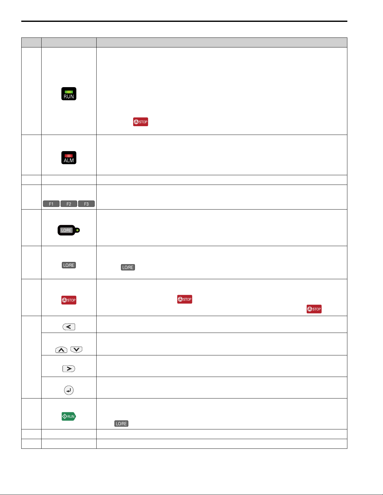
8 Keypad: Names and Functions
Table 8.1 Keypad: Names and Functions
No. Name Function
Illuminates to show that the drive is operating the motor.
The LED turns OFF when the drive stops.
Flashes to show that:
• The drive is decelerating to stop.
• The drive received a Run command but the frequency reference is 0 Hz.
RUN LED
A
ALM LED
B
C microSD Card Insertion Slot
Function Keys
D
(F1, F2, F3)
Flashes quickly to show that:
• The drive received a Run command from the Multi-Function Digital Input (MFDI) terminals and is switching to REMOTE Mode while
the drive is in LOCAL Mode.
• The drive received a Run command from the MFDI terminals when the drive is not in Drive Mode.
• The drive received a Fast Stop command.
• The safety function shuts off the drive output.
• The user pushed on the keypad while the drive is operating in REMOTE Mode.
• The drive is energized with an active Run command and b1-17 = 0 [Run Command at Power Up = Disregard Existing RUN Command].
Illuminates when the drive detects a fault.
Flashes when the drive detects:
• Alarm
• An oPE parameter setting error
• A fault or alarm during Auto-Tuning
The light switches off when the drive is in normal operation. There is no fault or alarm.
The insertion point for a microSD card.
The menu shown on the keypad sets the functions for function keys.
The name of each function is in the lower half of the display window.
E
F
G
H
I
J
K RJ-45 Connector
LO/RE LED
LO/RE Selection Key
STOP Key
Left Arrow Key Moves the cursor to the left.
Up Arrow Key/Down Arrow
Right Arrow Key (RESET)
Key
/
ENTER Key
RUN Key
USB Terminal
Illuminated: The keypad controls the Run command (LOCAL Mode).
OFF: The control circuit terminal or serial transmission device controls the Run command (REMOTE Mode).
Note:
• LOCAL: Operated using the keypad. Use the keypad to enter Run/Stop commands and the frequency reference command.
• REMOTE: Operated from the control circuit terminal or serial transmission. Use the frequency reference source entered in b1-01 and
the Run command source selected in b1-02.
Switches drive control for the Run command and frequency reference between the keypad (LOCAL) and an external source (REMOTE).
Note:
• Stop operation to enable the LO/RE Selection Key when in Drive Mode. Set o2-01 = 0 [LO/RE Key Function Selection = Disabled] to
disable when switching from REMOTE to LOCAL will have a negative effect on system performance.
• The drive will not switch between LOCAL and REMOTE when it is receiving a Run command from an external source.
Stops drive operation.
Note:
The STOP key has highest priority. Push to stop the motor even when a Run command (REMOTE Mode) is active at any
external Run command source. Set o2-02 = 0 [STOP Key Function Selection = Disabled] to disable the priority in .
• Scrolls up or down to display the next item or the previous item.
• Selects parameter numbers, and increments or decrements setting values.
• Moves the cursor to the right.
• Continues to the next screen.
• Clears drive faults.
• Enters parameter values and settings.
• Selects menu items to move the user between keypad displays.
• Selects each mode, parameter, and set value.
Starts the drive in LOCAL mode.
Starts the motor tuning procedure in Auto-Tuning Mode.
Note:
Push on the keypad to set the drive to LOCAL Mode before using the keypad to operate the motor.
Insertion point for a mini USB cable. Uses a USB cable (USB standard 2.0, type A - mini-B) to connect the keypad to a PC.
Connects to the drive using an RJ-45 8-pin straight through UTP CAT5e extension cable or keypad connector.
44 YASKAWA TOEPC71061737B GA800 Drive Installation & Primary Operation
Page 45

No. Name Function
Cover for the clock battery.
Note:
• The battery included with the keypad is for operation check. It may be exhausted earlier than the expected battery life described in the
manual.
L Clock Battery Cover
M Insulation Sheet
N Name Plate
• Refer to “Maintenance & Troubleshooting Manual (TOEPYAIGA8001)” for details on replacement procedure.
To replace the battery, use a Hitachi Maxell “CR2016 Lithium Manganese Dioxide Lithium Battery” or an equivalent battery with these
properties:
• Nominal voltage: 3 V
• Operating temperature range: -20°C to +85°C (-4°F to +185°F)
An insulating sheet is attached to the keypad battery to prevent battery drain. Remove the insulation sheet before you use the keypad for the
first time.
Shows the model, lot number, and FLASH number of the keypad.
Note:
Make sure that you use a keypad with FLASH number 1004 or later. Keypads with FLASH numbers 1003 and earlier will not show
characters correctly.
8 Keypad: Names and Functions
WARNING
Sudden Movement Hazard. If you change the control source when b1-07 = 1 [LOCAL/REMOTE Run Selection =
Accept Existing RUN Command], the drive can start suddenly. Before you change the control source, remove all personnel from the
area around the drive, motor, and load. Sudden starts can cause serious injury or death.
YASKAWA TOEPC71061737B GA800 Drive Installation & Primary Operation 45
Page 46

8 Keypad: Names and Functions
◆ Keypad Mode and Menu Displays
Figure 8.2 Keypad Functions and Display Levels
46 YASKAWA TOEPC71061737B GA800 Drive Installation & Primary Operation
Page 47

8 Keypad: Names and Functions
Note:
• Energize the drive with factory defaults to show the Initial Setup screen. Push (Home) to show the HOME screen.
–Select [No] from the [Show Initial Setup Screen] setting to not display the Initial Setup screen.
• Push from the Home screen to show drive monitors.
• Push to set d1-01 [Reference 1] when the Home screen shows U1-01 [Frequency Reference] in LOCAL Mode.
• The keypad will show [Rdy] when the drive is in Drive Mode. The drive is prepared to accept a Run command.
• The drive will not accept a Run command in Programming Mode in the default setting. Set b1-08 [Run Command Select in PRG Mode] to
accept or reject a Run command from an external source while in Programming Mode.
–Set b1-08 = 0 [Disregard RUN while Programming] to reject the Run command from an external source while in Programming Mode
(default).
–Set b1-08 = 1 [Accept RUN while Programming] to accept the Run command from an external source while in Programming Mode.
–Set b1-08 = 2 [Allow Programming Only at Stop] to prevent changes from Drive Mode to Programming Mode while the drive is
operating.
Table 8.2 Drive Mode Screens and Functions
Mode Keypad Screen Function
Drive Mode Monitors
Programming Mode
Parameters
User Custom Parameters
Parameter Backup/Restore
Modified Parameters/Fault Log
Auto-Tuning
Initial Setup
Diagnostic Tools
Sets monitor items to display.
Changes parameter settings.
Shows the User Parameters.
Saves parameters to the keypad as backup.
Shows modified parameters and fault history.
Auto-Tunes the drive.
Changes initial settings.
Sets data logs and backlight.
YASKAWA TOEPC71061737B GA800 Drive Installation & Primary Operation 47
Page 48

9 LED Status Ring
9 LED Status Ring
The LED Status Ring on the drive cover shows the drive operating status.
A - ALM/ERR
C - RUN
B - Ready
LED Status Description
The drive detects a fault.
The drive detects:
• An alarm
• An oPE parameter setting error
• An Auto-Tuning error
Note:
The LED will illuminate to identify a fault if the drive detects a fault and an alarm at the same time.
There are no drive faults or alarms.
The drive is operating or is prepared for operation.
The drive is in STo [Safe Torque OFF] condition.
The voltage of the main circuit power supply dropped, and only the external 24 V power supply provides the power to the
*1
drive.
• The drive detects a fault.
• There is no fault and the drive received a Run command, but the drive cannot operate. For example, in Programming
Mode or when is flashing.
The drive is in regular operation.
• The drive is decelerating to stop.
• The drive received a Run command with a frequency reference of 0 Hz, but the drive is not set for zero speed control.
• The drive received a DC Injection Braking command.
• The drive received a Run command from the MFDI terminals and is switching to REMOTE Mode while the drive is in
LOCAL Mode.
• The drive received a Run command from the MFDI terminals when the drive is not in Drive Mode.
• The drive received a Fast Stop command.
• The safety function shuts off the drive output.
*1
• The user pushed on the keypad while the drive is operating in REMOTE Mode.
• The drive is energized with an active Run command and b1-17 = 0 [Run Command at Power Up = Disregard Existing
RUN Command].
• The drive is set to coast-to-stop with timer (b1-03 = 3 [Stopping Method Selection = Coast to Stop with Timer]), and the
Run command is disabled then enabled during the Run wait time.
The motor is stopped.
A ALM/ERR
B Ready
C RUN
Illuminated
*1
Flashing
OFF
Illuminated
*1
Flashing
Flashing Quickly
OFF
Illuminated
*1
Flashing
Flashing Quickly
OFF
*1 Refer to Figure 9.1 for the difference between “flashing” and “flashing quickly”.
48 YASKAWA TOEPC71061737B GA800 Drive Installation & Primary Operation
Page 49

10 Drive Start-Up Procedure
/
Figure 9.1 LED Flashing Statuses
Figure 9.2 Relation between RUN LED and Drive Operation
10 Drive Start-Up Procedure
1. Install and wire the drive.
2. Energize the drive.
3. Use A1-06 [Application Preset] to initialize the drive for a special application if necessary.
4. Run the Setup Wizard to automatically set these functions:
• Control method selection
• HD/ND selection
• Motor data
• Frequency reference
• Run command source
• Acceleration and deceleration times
5. Run the motor without a load.
6. Make sure that the drive is operating correctly and make sure that the host controller is sending commands to the
drive.
7. Connect the load.
8. Run the motor.
9. Make sure that the drive is operating correctly.
10. Fine-tune and set application parameters, such as PID.
11. Do a final operation check and make sure that parameter settings are correct.
The drive is prepared to run the operation.
◆ Setup Wizard
Refer to the motor nameplate and record the information in this table before you start the drive.
Item Value
Motor Rated Power kW
Motor Rated Voltage V
Motor Rated Current A
Motor Rated Frequency Hz
Motor Maximum Frequency Hz
Number of Motor Poles
YASKAWA TOEPC71061737B GA800 Drive Installation & Primary Operation 49
Poles
Page 50

10 Drive Start-Up Procedure
Item Value
Motor Base Rotation Speed min
Number of Motor Encoder Pulses ppr
-1
(r/min)
The drive setup wizard prepares the drive for operation. Use the information from the table for Auto-Tuning and test
runs.
1. Energize the drive to show the initial setup screen.
Note:
If the keypad does not show the Initial Setup screen, push (Menu) to show the Menu screen then push to select
[Initial Setup].
2. Select [Set Date/Time] to set the date and time.
Note:
Open the clock battery cover to put in a battery to use the clock functions. Use a Hitachi Maxell CR2016 manganese dioxide
lithium battery or an equivalent battery with these properties:
• Nominal voltage: 3 V
• Operating temperature range: -20 °C to +85 °C (-4 °F to +185 °F)
• Nominal battery life: 2 years (20 °C (68 °F) ambient temperature)
3. Select [Setup Wizard] and follow the instructions shown on the keypad until the setup wizard completes.
The drive and motor are prepared for operation.
Note:
Refer to Disable the Initial Setup Screen on page 52 to stop showing the Initial Setup screen when you energize the drive.
◆ Change Parameter Settings
This example shows how to change the setting value for C1-01 [Acceleration Time 1]. Do the steps in this procedure
to set parameters for the application.
1. Push (Home) to show the HOME screen.
Note:
• When the drive is in HOME Mode, the screen shows [Home] in the upper right-hand corner of the screen.
• If [Home] is not shown above the , push (Back).
2. Push (Menu).
50 YASKAWA TOEPC71061737B GA800 Drive Installation & Primary Operation
Page 51

3. Push or to select [Parameters], then push .
4. Push or to select [C Tuning], then push .
5. Push or to select [C1 Accel & Decel Time], then push .
10 Drive Start-Up Procedure
6. Push or to select C1-01, then push .
7. Push or to select the specified digit, then push or to select the correct number.
• Push [Default] to set the parameters to factory defaults.
• Push [Min/Max] to show the minimum value or the maximum value on the display.
8. Push to keep the changes.
9. Continue to change parameters, then push [Back], [Home] to go back to the home screen after
you change all the applicable parameters.
YASKAWA TOEPC71061737B GA800 Drive Installation & Primary Operation 51
Page 52

10 Drive Start-Up Procedure
◆ Disable the Initial Setup Screen
Do the steps in this procedure to not show the initial start-up screen when the drive is energized.
1. Push (Home) to show the HOME screen.
Note:
• When the drive is in HOME Mode, the screen shows [Home] in the upper right-hand corner of the screen.
• If the screen does not show [Home] for , push (Back), and then push to show [Home].
2. Push (Menu).
3. Push / to select [Initial Setup], then push .
4. Push / to select [Show Initial Setup Screen], then push .
5. Push / to select [No], then push .
• [No]: The keypad will not show the Initial Setup Screen when the drive is energized.
• [Yes]: The keypad will show the Initial Setup Screen when the drive is energized.
◆ Control Circuit Terminal Block Functions
Hx-xx parameters set functions for the multi-function input and output terminals.
WARNING
correctly. If you use a drive that has incorrect control circuit wiring or operation, it can cause death or serious injury.
WARNING
Application Preset function. When you set the Application Preset function (A1-06 ≠ 0), it changes the I/O terminal functions for the
drive and it can cause equipment to operate unusually. This can cause serious injury or death.
Sudden Movement Hazard. Correctly wire and test all control circuits to make sure that the control circuits operate
Sudden Movement Hazard. Check the I/O signals and the external sequences for the drive before you set the
52 YASKAWA TOEPC71061737B GA800 Drive Installation & Primary Operation
Page 53

10 Drive Start-Up Procedure
NOTICE
The drive can fail if users frequently turn the drive ON and OFF with the MC on the power source side to Run and
Stop the drive. Incorrect operation can decrease the service life of the relay contacts and electrolytic capacitors. If you frequently
use the magnetic contactor on the power source side to Run and Stop the drive, it can cause drive failure.
■ Input Terminals
Refer to Table 10.1 for a list of input terminals and functions.
Table 10.1 Multi-function Input Terminals
Type Terminal Name (Default) Function (Signal Level)
MFDI selection 1
S1
(ON: Forward run OFF: Stop)
• Photocoupler
• 24 V, 6 mA
Note:
Install the wire jumpers between terminals SC-SP and SC-SN to set the MFDI power supply
(sinking/sourcing mode or internal/external power supply).
• Sinking Mode: Install a jumper between terminals SC and SP.
NOTICE
Do not close the circuit between terminals SC and
SN. A closed circuit between these terminals will cause damage to
the drive.
• Sourcing Mode: Install a jumper between terminals SC and SN.
NOTICE
Do not close the circuit between terminals SC and
SP. A closed circuit between these terminals will cause damage to
the drive.
• External power supply: No jumper necessary between terminals SC-SN and terminals SC-SP.
MFDI power supply, 24 V (maximum 150 mA)
NOTICE
Do not close the circuit between terminals SP and SN.
A closed circuit between these terminals will cause damage to the drive.
Remove the jumper between terminals H1-HC and H2-HC to use the Safe Disable input.
• 24 V, 6 mA
• ON: Normal operation
• OFF: Coasting motor
• Internal impedance 4.7 kΩ
• OFF Minimum OFF time of 2 ms.
Safe Disable function common
NOTICE
Do not close the circuit between terminals HC and SN.
A closed circuit between these terminals will cause damage to the drive.
Digital Inputs
Safe Disable
Input
MFDI selection 2
S2
(ON: Reverse run OFF: Stop)
MFDI selection 3
S3
(External fault (N.O.))
MFDI selection 4
S4
(Fault reset)
MFDI selection 5
S5
(Multi-step speed reference 1)
MFDI selection 6
S6
(Multi-step speed reference 2)
MFDI selection 7
S7
(Jog command)
MFDI selection 8
S8
(Baseblock command (N.O.))
SN MFDI power supply 0 V
SC MFDI selection common
SP MFDI power supply +24 Vdc
H1 Safe Disable input 1
H2 Safe Disable input 2
HC Safe Disable function common
YASKAWA TOEPC71061737B GA800 Drive Installation & Primary Operation 53
Page 54

10 Drive Start-Up Procedure
Type Terminal Name (Default) Function (Signal Level)
• Response frequency: 0 Hz to 32 kHz
• H level duty: 30% to 70%
• H level voltage: 3.5 V to 13.2 V
• L level voltage: 0.0 V to 0.8 V
• Input impedance: 3 kΩ
Voltage input or current input
Select terminal A1 with DIP switch S1-1 and H3-01 [Terminal A1 Signal Level Select].
Select terminal A2 with DIP switch S1-2 and H3-09 [Terminal A2 Signal Level Select]
• -10 V to +10 V/-100% to +100% (input impedance: 20 kΩ)
• 0 V to 10 V/100% (input impedance: 20 kΩ)
• 4 mA to 20 mA/100%, 0 mA to 20 mA/100% (input impedance: 250 Ω)
• Voltage input or current input
Select using DIP switch S1-3 and H3-05 [Terminal A3 Signal Level Select].
– -10 V to +10 V/-100% to +100% (input impedance: 20 kΩ)
– 0 V to 10 V/100% (input impedance: 20 kΩ)
– 4 mA to 20 mA/100%, 0 mA to 20 mA/100% (input impedance: 250 Ω)
• PTC input (Motor Overheat Protection)
Set DIP switch S4 to “PTC” and set DIP switch S1-3 to “V” to set terminal A3 for PTC input.
Master
Frequency
Reference
Master frequency reference pulse train input
RP
(Master frequency reference)
+V Power supply for frequency setting 10.5 V (allowable current 20 mA maximum)
-V Power supply for frequency setting -10.5 V (allowable current 20 mA maximum)
MFAI1
A1
(Master frequency reference)
MFAI2
A2
(Combined to terminal A1)
MFAI3/PTC input
A3
(Auxiliary frequency reference)
AC Frequency reference common 0 V
E (G) Connecting shielded cable -
■ Output Terminals
Refer to Table 10.2 and Table 10.3 for a list of output terminals and functions.
Table 10.2 Control Circuit Output Terminals
Type Terminal Name (Default) Function (Signal Level)
N.O. output
MA
(Fault) • Relay output
Fault Relay
Output
MFDO
N.C. output
MB
(Fault)
MC Digital output common
M1
MFDO
(During Run)
M2
M3
MFDO
(Zero Speed)
M4
M5
MFDO
(Speed Agree 1)
M6
Table 10.3 Control Circuit Monitor Output Terminals
Type Terminal Name (Default) Function (Signal Level)
Pulse train output
MP
(Output frequency)
Analog monitor output 1
FM
(Output frequency)
Monitor Output
Analog monitor output 2
AM
(Output current)
AC Monitor common 0 V
• 30 Vdc, 10 mA to 1 A
• 250 Vac, 10 mA to 1 A
• Minimum load: 5 V, 10 mA (Reference value)
• Relay output
• 30 Vdc, 10 mA to 1 A
• 250 Vac, 10 mA to 1 A
• Minimum load: 5 V, 10 mA (Reference value)
Note:
Do not set functions that frequently switch ON/OFF to MFDO (M1 to M6) because this will
decrease the performance life of the relay contacts. Yaskawa estimates switching life at
200,000 times (assumes 1 A, resistive load).
32 kHz (maximum)
Refer to “Pulse Train Output” on page 60 for more information.
Select voltage or current output.
• 0 V to 10 V/0% to 100%
• -10 V to +10 V/-100% to +100%
• 4 mA to 20 mA (receiver recommended impedance: 250 Ω)
Note:
Select with jumper switch S5 and H4-07 [Terminal FM Signal Level Select] or H4-08
[Terminal AM Signal Level Select].
54 YASKAWA TOEPC71061737B GA800 Drive Installation & Primary Operation
Page 55

10 Drive Start-Up Procedure
■ External Power Supply Input Terminals
Refer to Table 10.4 for a list of the functions of the external power supply input terminals.
Table 10.4 External Power Supply Input Terminals
Type Terminal Name (Default) Function
External Power Supply Input
Terminals
PS External 24 V power supply input
AC External 24 V power supply ground 0 V
Supplies backup power to the drive control circuit, keypad, and option board.
21.6 VDC to 26.4 VDC, 700 mA
■ Serial Communication Terminals
Refer to Table 10.5 for a list of serial communication terminals and functions.
Table 10.5 Serial Communication Terminals
Type Terminal Terminal Name Function (Signal Level)
Modbus Communication
D+
D-
AC Signal ground
Communication
input/output (+)
Communication
output (-)
MEMOBUS/Modbus communications
Use an RS-485 cable to connect the drive.
Note:
Set DIP switch S2 to ON to enable the
termination resistor in the last drive in a
MEMOBUS/Modbus network.
0 V
• RS-485
• MEMOBUS/Modbus communication protocol
• Maximum 115.2 kbps
◆ Control Circuit Terminal Configuration
The control circuit terminals are in the positions shown in Figure 10.1.
A - Terminal block (TB5)
B - Terminal block (TB2-3)
C - Terminal block (TB2-2)
D - Terminal block (TB2-1)
Figure 10.1 Control Circuit Terminal Arrangement
The tightening torque for the terminal screws is shown on the reverse side or the lower front side of the front cover.
E - Terminal block (TB1)
F - Terminal block (TB3)
G - Terminal block (TB4)
YASKAWA TOEPC71061737B GA800 Drive Installation & Primary Operation 55
Page 56

10 Drive Start-Up Procedure
Figure 10.2 Tightening Torque Display Location (Reverse side of Front Cover)
Figure 10.3 Tightening Torque Display Location (Lower Front Side of Front Cover)
■ Control Circuit Wire Gauges and Tightening Torques
Use the tables in this section to select the correct wires. Use shielded wire to wire the control circuit terminal block.
Use crimp ferrules on the wire ends to make the wiring procedure easier and more reliable.
Table 10.6 Control Circuit Wire Gauges and Tightening Torques
Termi
nal
Block
TB1 S1 - S8, SN, SC, SP
TB2 M1 - M6, MA, MB, MC
+V, AC, -V, A1, A2, A3, FM, AM,
TB3
AC, MP, RP, AC
E (G), SN, HC, H1, H2, PS, AC, D+,
TB4
D-
TB5 E (G) M3.5
Terminal Screw Size
M3
Tightening
Torque
N∙m (in∙lb)
0.5 - 0.6
(4.4 - 5.3)
0.5 - 1.0
(4.4 - 8.9)
Recommended
mm
Crimp Ferrules
Attach an insulated sleeve when you use crimp ferrules. Refer to Table 10.7 for the recommended external
dimensions and model numbers of the crimp ferrules.
Use the CRIMPFOX 6, a crimping tool made by PHOENIX CONTACT.
Bare Wire Crimp Ferrule
Gauge
2
(AWG)
0.75
(18)
0.5 - 2
(20 - 14)
Applicable
Gauge
mm2(AWG)
• Stranded wire
0.2 - 1.0
(24 - 16)
• Solid wire
0.2 - 1.5
(24 - 16)
1.25
(12)
Recommended
Gauge
mm2(AWG)
Applicable
mm2(AWG)
0.5
(20)
- -
Gauge
0.25 - 0.5
(24 - 20)
56 YASKAWA TOEPC71061737B GA800 Drive Installation & Primary Operation
Page 57

Figure 10.4 External Dimensions of Crimp Ferrules
Table 10.7 Crimp Ferrule Models and Sizes
Wire Gauge
2
mm
(AWG)
0.25 (24) AI 0.25-8YE 12.5 8 0.8 2.0
0.34 (22) AI 0.34-8TQ 12.5 8 0.8 2.0
0.5 (20)
Model L (mm) L1 (mm) φd1 (mm) φd2 (mm)
AI 0.5-8WH,
AI 0.5-8OG
14 8 1.1 2.5
◆ Wiring the Control Circuit Terminal
10 Drive Start-Up Procedure
WARNING
Electrical Shock Hazard. Do not remove covers or touch circuit boards while the drive is energized. If you touch
the internal components of an energized drive, it can cause serious injury or death.
NOTICE
Do not let wire shields touch other signal lines or equipment. Insulate the wire shields with electrical tape or shrink
tubing. If you do not insulate the wire shields, it can cause a short circuit and damage the drive.
Note:
• Isolate control circuit wiring from main circuit wiring (terminals R/L1, S/L2, T/L3, B1, B2, U/T1, V/T2, W/T3, -, +1, +2) and other high-
power wiring. If the control circuit wires are adjacent to the main circuit wires, the drive or the devices around the drive may malfunction
due to electrical interference.
• Isolate contact output terminals MA, MB, MC and M1-M6 from other control circuit wiring. If the output terminal wires are adjacent to
other control circuit wires, the drive or devices around it may malfunction due to electrical interference.
• Connect the control circuit to a power supply of Class 2 (UL standard). Improper application of peripheral devices could result in drive
performance degradation due to improper power supply.
• Connect the shield of shielded cable to the applicable ground terminal. If the grounding is not correct, the drive or devices around it may
malfunction due to electrical interference.
Correctly ground the drive terminals and complete main circuit wiring before you wire the control circuit. Remove the
keypad and front cover.
1. Push in on the tabs on the both sides of the LED status ring board to release the board from the bracket. Pull
the board forward to remove it.
NOTICE
in the holding position provided on the drive. If you cause damage to the LED status ring board, the LEDs will not function
correctly.
Note:
You can temporarily store the LED status ring board with the temporary placement holes on the drive. The location of the
temporary placement holes is different on different drive models.
When you remove the LED Status Board from the drive bracket, make sure that you temporarily install it
A - Drive front
C - Temporary placement holes
B - LED status ring board
Figure 10.5 Remove the LED Status Ring Board
YASKAWA TOEPC71061737B GA800 Drive Installation & Primary Operation 57
Page 58

10 Drive Start-Up Procedure
A - Drive front
B - LED status ring board
Figure 10.6 Remove the LED Status Ring Board
A - Drive front
B - LED status ring board
Figure 10.7 Remove the LED Status Ring Board
C - Temporary placement holes
C - Temporary placement holes
2. Refer to the following figure and wire the control circuit.
WARNING
or too tight can cause incorrect operation and damage to the drive. Incorrect connections can also cause death or serious
injury from fire.
Note:
• To prevent malfunction due to electrical interference, use shielded wires and shielded twisted-pair wires for the control circuit
terminal wiring. If the grounding is not correct, the drive or devices around it may malfunction due to electrical interference.
• Do not use control circuit wiring that is longer than 50 m (164 ft) to supply the frequency reference with an analog signal from a
remote source. Failure to observe this could cause unsatisfactory system performance.
Fire Hazard. Tighten all terminal screws to the correct tightening torque. Connections that are too loose
58 YASKAWA TOEPC71061737B GA800 Drive Installation & Primary Operation
Page 59

10 Drive Start-Up Procedure
A - Loosen the screws and put the wire
into the opening on the terminal
block.
B - Wire with a crimp ferrule attached,
or unsoldered wire with the core
wires lightly twisted
C - Pull back the shielding and lightly
twist the end with your fingers to
keep the ends from fraying.
Figure 10.8 Wiring Procedure for the Control Circuit
Note:
• Do not solder the core wire. Soldered wire connections can become loose over time and cause unsatisfactory drive
performance.
• Tighten all terminal screws to the correct tightening torque. Connections that are too loose or too tight can cause incorrect
operation and damage to the drive. Incorrect connections can also cause death or serious injury from fire.
• Refer to Figure 10.9 for information to prepare terminal ends of the shielded wire.
• Prepare the wire ends of shielded twisted-pair wires as shown in Figure 10.9 to use an analog reference from an external
frequency setting potentiometer to set the frequency. Connect the shield to terminal E (G) of the drive.
D - Remove approximately 5.5 mm
(0.21 in) of the covering at the end
of the wire if you do not use crimp
ferrules.
E - Blade width of 2.5 mm (0.1 in) or
less
F - Blade depth of 0.4 mm (0.01 in) or
less
A - Connect the shield to terminal E (G)
of the drive.
B - Sheath
Figure 10.9 Prepare the Ends of Shielded Wire
C - Insulate with electrical tape or
shrink tubing.
3. Put the cable through the clearance in the wiring cover.
Figure 10.10 Control Circuit Wiring
4. Install the LED status ring board, front cover, and the keypad to their initial positions.
YASKAWA TOEPC71061737B GA800 Drive Installation & Primary Operation 59
Page 60

10 Drive Start-Up Procedure
◆ Switches and Jumpers on the Terminal Board
The terminal board has switches to adapt the drive I/Os to the external control signals as shown in Figure 10.11.
Set the switches to select the functions for each terminal.
Figure 10.11 Locations of Switches
Table 10.8 I/O Terminals and Switches Functions
Posi
tion
A DIP switch S2 -
B Jumper switch S5 FM, AM Sets terminals FM and AM to voltage or current output.
C
D Dip switch S4 A3 Selects MFAI or PTC input. AI (analog input)
Switch Terminal Function Default Setting
Enables and disables the MEMOBUS/Modbus communications
termination resistor.
DIP switch S1-1 A1 Selects the input signal type (voltage/current). V (voltage input)
DIP switch S1-2 A2 Selects the input signal type (voltage/current). I (current input)
DIP switch S1-3 A3 Selects the input signal type (voltage/current). V (voltage input)
OFF
FM: V (voltage output)
AM: V (voltage output)
◆ Control I/O Connections
This section gives information about the settings for the listed control circuit I/O signals.
• MFDI (terminals S1 to S8)
• Pulse train output (terminal MP)
• MFAI (terminals A1 to A3)
• PTC input (terminal A3)
• MFAO (terminals FM, AM)
• MEMOBUS/Modbus communications (terminals D+, D-, AC)
■ Pulse Train Output
You can use pulse train monitor output terminal MP for sourcing mode or for sinking mode.
• Use for sourcing mode
The load impedance changes the voltage level of the pulse train output signal.
Load Impedance
R
(kΩ)
L
1.5 kΩ or more 5 V or more
4.0 kΩ or more 8 V or more
10 kΩ or more 10 V or more
Note:
Use the formula in Figure 10.12 to calculate the necessary load resistance (kΩ) to increase output voltage V
Output Voltage
VMP(V)
MP
(V).
60 YASKAWA TOEPC71061737B GA800 Drive Installation & Primary Operation
Page 61

10 Drive Start-Up Procedure
A - Load Impedance
Figure 10.12 Wiring to Use Pulse Train Output in Sourcing Mode
• Use in sinking mode
The external power supply changes the voltage level of the pulse train output signal. Keep the voltage from an
external source between 10.8 Vdc to 16.5 Vdc. Adjust the load impedance to keep the current at 16 mA or lower.
External Power Supply (V) Load Impedance (kΩ) Sinking current (mA)
10.8 Vdc to 16.5 Vdc 1.0 kΩ or more 16 mA maximum
A - External power supply
B - Load Impedance
Figure 10.13 Wiring to Use Pulse Train Output in Sinking Mode
C - Sinking current
■ Set Sinking Mode/Sourcing Mode
Close the circuit between terminals SC-SP and SC-SN to set the sinking mode/sourcing mode and the internal/
external power supply for the MFDI terminals. The default setting for the drive is internal power supply sinking
mode.
NOTICE
damage to the drive.
Do not close the circuit between terminals SP and SN. A closed circuit between these terminals will cause
YASKAWA TOEPC71061737B GA800 Drive Installation & Primary Operation 61
Page 62

10 Drive Start-Up Procedure
Mode Internal Power Supply (Terminal SN-SP) External 24 V power supply
Sinking Mode (NPN)
Sourcing Mode
(PNP)
■ Set Input Signals for MFAI Terminals A1 to A3
Use terminals A1 to A3 to input a voltage or a current signal. Set the signal type as shown in Table 10.9.
Figure 10.14 Location of DIP Switch S1
Table 10.9 MFAI Terminals A1 to A3 Signal Settings
Terminal Input Signal
Voltage input
A1
Current input I
Voltage input
A2
Current input
Voltage input
A3
Current input I
DIP Switch Settings Parameter
Switch Setting No. Signal Level
S1-1
S1-2
S1-3
V
(Default)
V
I
(Default)
V
(Default)
H3-01
H3-09
H3-05
0: 0 V to 10 V/0% to 100% (input impedance: 20 kΩ)
1: -10 V to +10 V/-100% to 100% (input impedance: 20 kΩ)
2: 4 mA to 20 mA/0% to 100% (input impedance: 250 Ω)
3: 0 mA to 20 mA/0% to 100% (input impedance: 250 Ω)
0: 0 V to 10 V/0% to 100% (input impedance: 20 kΩ)
1: -10 V to +10 V/-100% to 100% (input impedance: 20 kΩ)
2: 4 mA to 20 mA/0% to 100% (input impedance: 250 Ω)
3: 0 mA to 20 mA/0% to 100% (input impedance: 250 Ω)
0: 0 V to 10 V/0% to 100% (input impedance: 20 kΩ)
1: -10 V to +10 V/-100% to 100% (input impedance: 20 kΩ)
2: 4 mA to 20 mA/0% to 100% (input impedance: 250 Ω)
3: 0 mA to 20 mA/0% to 100% (input impedance: 250 Ω)
62 YASKAWA TOEPC71061737B GA800 Drive Installation & Primary Operation
Page 63

10 Drive Start-Up Procedure
Note:
• Set H3-02, H3-10 = 0 [Terminal A1 Function Selection, Terminal A2 Function Selection = Frequency Reference] to set A1 and A2 to
frequency reference. The drive will add the analog input values together to make the frequency reference.
• Use tweezers or a jig with a tip width of approximately 0.8 mm (0.03 in) to set DIP switches.
• Set DIP switch S4 to “AI” to use terminal A3 as an analog input (voltage/current) terminal. The default setting for DIP switch S4 is “AI”.
■ Set MFAI Terminal A3 to PTC Input
Set terminal A3 as an MFAI or as the PTC input for motor overload protection.
Use DIP switch S4 to set the input function.
Figure 10.15 Location of DIP Switch S4
Terminal Settings for DIP Switches Description
AI
(Default)
A3
PTC
Functions as an MFAI terminal.
Set H3-06 [Terminal A3 Function Selection] to select the input function.
Functions as the PTC input terminal.
Set H3-06 = E [Motor Temperature (PTC Input)].
Set S1-3 to “V” for voltage input.
■ Set Output Signals for MFAO Terminals FM, AM
Set the signal type for terminals AM and FM to voltage or current output. Use jumper switch S5 and H4-07, H4-08
[Terminal FM Signal Level Select, Terminal AM Signal Level Select] to set the signal type.
Figure 10.16 Location of Jumper Switch S5
YASKAWA TOEPC71061737B GA800 Drive Installation & Primary Operation 63
Page 64

11 Drive Control, Duty Modes, and Programming
Terminal Types of Output Signals Jumper Switch S5
Voltage output
(Default)
FM
Current output 2: 4 mA to 20 mA
Voltage output
(Default)
AM
Current output 2: 4 mA to 20 mA
No. Signal Level
H4-07
H4-08
Parameter
0: 0 V to 10 V
1: -10 V to +10 V
0: 0 V to 10 V
1: -10 V to +10 V
■ Switch ON Termination Resistor for MEMOBUS/Modbus Communications
When the drive is the last slave in a MEMOBUS/Modbus communications, set DIP switch S2 to the ON position.
This drive has a built-in termination resistor for the RS-485 interface.
Figure 10.17 Location of DIP Switch S2
Table 10.10 MEMOBUS/Modbus Communications Termination Resistor Setting
DIP Switch S2 Description
ON The built-in termination resistor is ON.
OFF (Default) The built-in termination resistor is OFF.
11 Drive Control, Duty Modes, and Programming
◆ Selecting the Control Method
This section gives information about these basic control methods:
• V/f Control
• Open Loop Vector Control (OLV)
• EZ Open Loop Vector Control (EZOLV) for induction motors only
Refer to the Technical Manual for information about speed feedback and Permanent Magnet/Synchronous Reluctance
motor control methods.
Use A1-02 [Control Method Selection] to select the most applicable control method for your application.
64 YASKAWA TOEPC71061737B GA800 Drive Installation & Primary Operation
Page 65

11 Drive Control, Duty Modes, and Programming
Control Method A1-02 Setting Main Applications
V/f 0
OLV
EZOLV 8
(Default)
2
• General variable-speed, best to operate more than one motor from one drive.
• When motor parameters are not available.
• General variable-speed
• High precision and high speed response without speed feedback
• General variable-speed
• No high precision, no high speed response, and no speed feedback
◆ Drive Duty Modes
The drive has two duty modes from which to select for the application: Heavy Duty (HD) and Normal Duty (ND).
• The input power
• The maximum applicable motor output
• The rated input current
• The rated output capacity
• The rated output current
Note:
The reference for the parameter set as a percentage of the drive rated output current is the rated output current of HD/ND.
Refer to Table 11.1 for information about the differences between HD and ND ratings.
Duty Rating
Heavy Duty
(HD)
Normal Duty
(ND)
Rating
Rating
kVA
C6-01
Setting
0
1
Table 11.1 Drive Duty Modes
Application Default Carrier Frequency
• Extruder
• Conveyor
• Constant torque or high overload capacity
• Fan
• Pump
• Blower
• Variable speed control
2 kHz
2 kHz Swing-PWM
Overload Tolerance (oL2 [Drive
150% of the rated output current for
60 seconds The permitted frequency
of overload is one time each 10
minutes.
110% of the rated output current for
60 seconds The permitted frequency
of overload is one time each 10
minutes.
Overload])
◆ Auto-Tuning
WARNING
this is a translation error. Please confirm it. Increased motor frequency can cause serious injury or death.
WARNING
cause serious injury or death.
Auto-Tuning automatically sets parameters on the drive connected to the motor. You must input some parameters
individually during Auto-Tuning.
1. Select [Auto-Tuning] from the main menu to select the Auto-Tuning Mode.
2. Use the information in Table 11.2 and Table 11.3 to set T1-01 [Auto-Tuning Mode Selection] and T4-01 [EZ
Tuning Mode Selection].
3. Push to start Auto-Tuning.
Refer to the Technical Manual for more information about Auto-Tuning.
Crush Hazard. This seems incorrect. The drive should not take a 60 Hz motor to 90 Hz during tuning. We thing
Before you do Rotational Auto-Tuning, disconnect the load from the motor. The load can move suddenly and
YASKAWA TOEPC71061737B GA800 Drive Installation & Primary Operation 65
Page 66

11 Drive Control, Duty Modes, and Programming
V/f
CL-V/f
OLV
CLV
AOLV
OLV/PM OLV/PM
AOLV/PM
CLV/PM
EZOLV
Table 11.2 Auto-Tuning Mode Selection
Type T1-01 Application Conditions and Benefits
Rotational Auto-Tuning 0
Stationary Auto-Tuning
1
Stationary Line-Line
Resistance
Type T4-01 Application Conditions and Benefits
Motor Parameter Setting 0
Line-to-Line Resistance 1
Recommended tuning mode for the most accurate results. Select this tuning mode when:
• You can decouple the motor from the load.
• You cannot decouple the motor from the load, but the motor load is less than 30%.
Automatically calculates motor parameters for vector control. Select this tuning mode when:
1
• You cannot decouple the motor from the load.
• The motor test report data is not available.
Select this tuning mode when:
• The drive and motor capacities are different.
2
• The drive is in V/f Control.
• You have replaced the drive and motor.
Table 11.3 EZ Tuning Mode Selection
Set the motor parameters.
Select this tuning mode after you replace the drive, motor, and motor cables.
A1-02 [Control
Method Selection]
0
[V/f]
- Yes
- Yes
Yes Yes
A1-02 = 8
[EZOLV]
2
[OLV]
Yes
Yes
◆ Drive Parameters
Icon Description
The parameter is available when operating the drive with V/f Control.
The parameter is available when operating the drive with Closed Loop V/f Control.
The parameter is available when operating the drive with Open Loop Vector Control.
The parameter is available when operating the drive with Closed Loop Vector Control.
The parameter is available when operating the drive with Advanced Open Loop Vector Control.
The parameter is available when operating the drive with Open Loop Vector Control for PM.
The parameter is available when operating the drive with Advanced Open Loop Vector Control for PM.
The parameter is available when operating the drive with Closed Loop Vector Control for PM.
The parameter is available when operating the drive with EZ Open Loop Vector Control.
RUN The parameter can be changed settings during run.
Note:
Gray icons identify parameters that are not available in the specified control method.
Refer to the following table when setting the most important parameters.
66 YASKAWA TOEPC71061737B GA800 Drive Installation & Primary Operation
Page 67

11 Drive Control, Duty Modes, and Programming
V/f
CL-V/f
OLV
CLV
AOLV
OLV/PM OLV/PM
AOLV/PM
CLV/PM
EZOLV
V/f
CL-V/f
OLV
CLV
AOLV
OLV/PM OLV/PM
AOLV/PM
CLV/PM
EZOLV
V/f
CL-V/f
OLV
CLV
AOLV
OLV/PM OLV/PM
AOLV/PM
CLV/PM
EZOLV
V/f
CL-V/f
OLV
CLV
AOLV
OLV/PM OLV/PM
AOLV/PM
CLV/PM
EZOLV
V/f
CL-V/f
OLV
CLV
AOLV
OLV/PM OLV/PM
AOLV/PM
CLV/PM
EZOLV
V/f
CL-V/f
OLV
CLV
AOLV
OLV/PM OLV/PM
AOLV/PM
CLV/PM
EZOLV
V/f
CL-V/f
OLV
CLV
AOLV
OLV/PM OLV/PM
AOLV/PM
CLV/PM
EZOLV
V/f
CL-V/f
OLV
CLV
AOLV
OLV/PM OLV/PM
AOLV/PM
CLV/PM
EZOLV
V/f
CL-V/f
OLV
CLV
AOLV
OLV/PM OLV/PM
AOLV/PM
CLV/PM
EZOLV
No.
(Hex.)
A1-00
(0100)
RUN
A1-02
(0102)
A1-03
(0103)
b1-01
(0180)
b1-02
(0181)
b1-03
(0182)
b1-04
(0183)
C1-01
(0200)
RUN
C1-02
(0201)
RUN
Name Description
Language Selection
Control Method Selection
Initialize Parameters
Frequency Reference Selection 1
Run Command Selection 1
Stopping Method Selection
Reverse Operation Selection
Acceleration Time 1
Deceleration Time 1
Sets the language for the LCD keypad.
0 : English
1 : Japanese
2 : German
3 : French
4 : Italian
5 : Spanish
6 : Portuguese
7 : Chinese
8 : Czech
9 : Russian
10 : Turkish
11 : Polish
12 : Greek
Sets the control method for the drive application and the motor.
0 : V/f Control
1 : V/f Control with Encoder
2 : Open Loop Vector
3 : Closed Loop Vector
4 : Advanced Open Loop Vector
5 : PM Open Loop Vector
6 : PM Advanced Open Loop Vector
7 : PM Closed Loop Vector
8 : EZ Vector Control
Sets parameters to default values.
0 : No Initialization
1110 : User Initialization
2220 : 2-Wire Initialization
3330 : 3-Wire Initialization
Sets the input method for the frequency reference.
0 : Keypad
1 : Analog Input
2 : Memobus/Modbus Communications
3 : Option PCB
4 : Pulse Train Input
Sets the input method for the Run command.
0 : Keypad
1 : Digital Input
2 : Memobus/Modbus Communications
3 : Option PCB
Sets the method to stop the motor after removing a Run command or entering a Stop command.
0 : Ramp to Stop
1 : Coast to Stop
2 : DC Injection Braking to Stop
3 : Coast to Stop with Timer
Sets the reverse operation function. Disable reverse operation in fan or pump applications where reverse rotation is
dangerous.
0 : Reverse Enabled
1 : Reverse Disabled
Sets the length of time to accelerate from zero to maximum output frequency.
Sets the length of time to decelerate from maximum output frequency to zero.
YASKAWA TOEPC71061737B GA800 Drive Installation & Primary Operation 67
Page 68

11 Drive Control, Duty Modes, and Programming
V/f
CL-V/f
OLV
CLV
AOLV
OLV/PM OLV/PM
AOLV/PM
CLV/PM
EZOLV
V/f
CL-V/f
OLV
CLV
AOLV
OLV/PM OLV/PM
AOLV/PM
CLV/PM
EZOLV
V/f
CL-V/f
OLV
CLV
AOLV
OLV/PM OLV/PM
AOLV/PM
CLV/PM
EZOLV
V/f
CL-V/f
OLV
CLV
AOLV
OLV/PM OLV/PM
AOLV/PM
CLV/PM
EZOLV
V/f
CL-V/f
OLV
CLV
AOLV
OLV/PM OLV/PM
AOLV/PM
CLV/PM
EZOLV
V/f
CL-V/f
OLV
CLV
AOLV
OLV/PM OLV/PM
AOLV/PM
CLV/PM
EZOLV
V/f
CL-V/f
OLV
CLV
AOLV
OLV/PM OLV/PM
AOLV/PM
CLV/PM
EZOLV
V/f
CL-V/f
OLV
CLV
AOLV
OLV/PM OLV/PM
AOLV/PM
CLV/PM
EZOLV
V/f
CL-V/f
OLV
CLV
AOLV
OLV/PM OLV/PM
AOLV/PM
CLV/PM
EZOLV
V/f
CL-V/f
OLV
CLV
AOLV
OLV/PM OLV/PM
AOLV/PM
CLV/PM
EZOLV
V/f
CL-V/f
OLV
CLV
AOLV
OLV/PM OLV/PM
AOLV/PM
CLV/PM
EZOLV
V/f
CL-V/f
OLV
CLV
AOLV
OLV/PM OLV/PM
AOLV/PM
CLV/PM
EZOLV
V/f
CL-V/f
OLV
CLV
AOLV
OLV/PM OLV/PM
AOLV/PM
CLV/PM
EZOLV
V/f
CL-V/f
OLV
CLV
AOLV
OLV/PM OLV/PM
AOLV/PM
CLV/PM
EZOLV
V/f
CL-V/f
OLV
CLV
AOLV
OLV/PM OLV/PM
AOLV/PM
CLV/PM
EZOLV
V/f
CL-V/f
OLV
CLV
AOLV
OLV/PM OLV/PM
AOLV/PM
CLV/PM
EZOLV
V/f
CL-V/f
OLV
CLV
AOLV
OLV/PM OLV/PM
AOLV/PM
CLV/PM
EZOLV
V/f
CL-V/f
OLV
CLV
AOLV
OLV/PM OLV/PM
AOLV/PM
CLV/PM
EZOLV
V/f
CL-V/f
OLV
CLV
AOLV
OLV/PM OLV/PM
AOLV/PM
CLV/PM
EZOLV
V/f
CL-V/f
OLV
CLV
AOLV
OLV/PM OLV/PM
AOLV/PM
CLV/PM
EZOLV
No.
(Hex.)
C2-01
(020B)
C2-02
(020C)
C2-03
(020D)
C2-04
(020E)
C6-01
(0223)
C6-02
(0224)
d1-01 to d1-16
(0280 - 0291)
RUN
d1-17
(0292)
RUN
d2-01
(0289)
d2-02
(028A)
E1-01
(0300)
E1-04
(0303)
E1-05
(0304)
E1-06
(0305)
E1-09
(0308)
E2-01
(030E)
E2-11
(0318)
H1-01 - H1-08
(0438, 0439, 0400 -
0405)
H2-01
(040B)
H2-02
(040C)
Name Description
S-Curve Time @ Start of Accel
S-Curve Time @ End of Accel
S-Curve Time @ Start of Decel
S-Curve Time @ End of Decel
Normal / Heavy Duty Selection
Carrier Frequency Selection
Reference 1 to 16
Jog Reference
Frequency Reference Upper Limit
Frequency Reference Lower Limit
Input AC Supply Voltage
Maximum Output Frequency
Maximum Output Voltage
Base Frequency
Minimum Output Frequency
Motor Rated Current (FLA)
Motor Rated Power
Terminal S1 to S8 Function
Selection
Term M1-M2 Function Selection
Term M3-M4 Function Selection
Sets the S-curve acceleration time at start.
Sets the S-curve acceleration time at completion.
Sets the S-curve deceleration time at start.
Sets the S-curve deceleration time at completion.
Sets the drive duty rating.
0 : Heavy Duty Rating
1 : Normal Duty Rating
Sets the carrier frequency for the transistors in the drive.
1 : 2.0 kHz
2 : 5.0 kHz (4.0 kHz AOLV/PM)
3 : 8.0 kHz (6.0 kHz AOLV/PM)
4 : 10.0 kHz (8.0 kHz AOLV/PM)
5 : 12.5 kHz (10.0 kHz AOLV/PM)
6 : 15.0 kHz (12.0 kHz AOLV/PM)
7 : Swing PWM1 (Audible Sound 1)
8 : Swing PWM2 (Audible Sound 2)
9 : Swing PWM3 (Audible Sound 3)
A : Swing PWM4 (Audible Sound 4)
F : User Defined (C6-03 to C6-05)
Sets the frequency reference in the units from o1-03 [Frequency Display Unit Selection].
Sets the Jog frequency reference in the units from o1-03 [Frequency Display Unit Selection]. Set H1-xx = 6 [MFDI
Function Select = Jog Reference Selection] to use the Jog frequency reference.
Sets maximum limit for all frequency references. The maximum output frequency is 100%.
Sets minimum limit for all frequency references. The maximum output frequency is 100%.
Sets the drive input voltage.
Sets the maximum output frequency for the V/f pattern.
Sets the maximum output voltage for the V/f pattern.
Sets the base frequency for the V/f pattern.
Sets the minimum output frequency for the V/f pattern.
Sets the motor rated current in amps.
Sets the motor rated output in the units from o1-58 [Motor Power Unit Selection].
Sets the functions for MFDI terminals S1 to S8.
Sets the function for MFDO terminal M1-M2.
Sets the function for MFDO terminal M3-M4.
68 YASKAWA TOEPC71061737B GA800 Drive Installation & Primary Operation
Page 69

11 Drive Control, Duty Modes, and Programming
V/f
CL-V/f
OLV
CLV
AOLV
OLV/PM OLV/PM
AOLV/PM
CLV/PM
EZOLV
V/f
CL-V/f
OLV
CLV
AOLV
OLV/PM OLV/PM
AOLV/PM
CLV/PM
EZOLV
V/f
CL-V/f
OLV
CLV
AOLV
OLV/PM OLV/PM
AOLV/PM
CLV/PM
EZOLV
V/f
CL-V/f
OLV
CLV
AOLV
OLV/PM OLV/PM
AOLV/PM
CLV/PM
EZOLV
V/f
CL-V/f
OLV
CLV
AOLV
OLV/PM OLV/PM
AOLV/PM
CLV/PM
EZOLV
V/f
CL-V/f
OLV
CLV
AOLV
OLV/PM OLV/PM
AOLV/PM
CLV/PM
EZOLV
V/f
CL-V/f
OLV
CLV
AOLV
OLV/PM OLV/PM
AOLV/PM
CLV/PM
EZOLV
V/f
CL-V/f
OLV
CLV
AOLV
OLV/PM OLV/PM
AOLV/PM
CLV/PM
EZOLV
V/f
CL-V/f
OLV
CLV
AOLV
OLV/PM OLV/PM
AOLV/PM
CLV/PM
EZOLV
V/f
CL-V/f
OLV
CLV
AOLV
OLV/PM OLV/PM
AOLV/PM
CLV/PM
EZOLV
V/f
CL-V/f
OLV
CLV
AOLV
OLV/PM OLV/PM
AOLV/PM
CLV/PM
EZOLV
V/f
CL-V/f
OLV
CLV
AOLV
OLV/PM OLV/PM
AOLV/PM
CLV/PM
EZOLV
V/f
CL-V/f
OLV
CLV
AOLV
OLV/PM OLV/PM
AOLV/PM
CLV/PM
EZOLV
V/f
CL-V/f
OLV
CLV
AOLV
OLV/PM OLV/PM
AOLV/PM
CLV/PM
EZOLV
V/f
CL-V/f
OLV
CLV
AOLV
OLV/PM OLV/PM
AOLV/PM
CLV/PM
EZOLV
V/f
CL-V/f
OLV
CLV
AOLV
OLV/PM OLV/PM
AOLV/PM
CLV/PM
EZOLV
No.
(Hex.)
H2-03
(040D)
H3-01
(0410)
H3-02
(0434)
H3-03
(0411)
RUN
H3-04
(0412)
RUN
H3-05
(0413)
H3-06
(0414)
H3-07
(0415)
RUN
H3-08
(0416)
RUN
H3-09
(0417)
H3-10
(0418)
H3-11
(0419)
RUN
H3-12
(041A)
RUN
H3-13
(041B)
H3-14
(041C)
H4-01
(041D)
Name Description
Term M5-M6 Function Selection
Terminal A1 Signal Level Select
Terminal A1 Function Selection
Terminal A1 Gain Setting
Terminal A1 Bias Setting
Terminal A3 Signal Level Select
Terminal A3 Function Selection
Terminal A3 Gain Setting
Terminal A3 Bias Setting
Terminal A2 Signal Level Select
Terminal A2 Function Selection
Terminal A2 Gain Setting
Terminal A2 Bias Setting
Analog Input FilterTime Constant
Analog Input Terminal Enable Sel
Terminal FM Analog Output Select
Sets the function for MFDO terminal M5-M6.
Sets the input signal level for MFAI terminal A1.
0 : 0 to 10V (Lower Limit at 0)
1 : -10 to +10V (Bipolar Reference)
2 : 4 to 20 mA
3 : 0 to 20 mA
Sets the function for MFAI terminal A1.
Sets the gain of the analog signal input to MFAI terminal A1.
Sets the bias of the analog signal input to MFAI terminal A1.
Sets the input signal level for MFAI terminal A3.
0 : 0 to 10V (Lower Limit at 0)
1 : -10 to +10V (Bipolar Reference)
2 : 4 to 20 mA
3 : 0 to 20 mA
Sets the function for MFAI terminal A3.
Sets the gain of the analog signal input to MFAI terminal A3.
Sets the bias of the analog signal input to MFAI terminal A3.
Sets the input signal level for MFAI terminal A2.
0 : 0-10V (LowLim=0)
1 : -10 to +10V (Bipolar Reference)
2 : 4 to 20 mA
3 : 0 to 20 mA
Sets the function for MFAI terminal A2.
Sets the gain of the analog signal input to MFAI terminal A2.
Sets the bias of the analog signal input to MFAI terminal A2.
Sets the time constant for primary delay filters on MFAI terminals.
Sets the enabled terminal or terminals when H1-xx = C [MFDI Function Select = Analog Terminal Enable Selection] is
ON.
1 : Terminal A1 only
2 : Terminal A2 only
3 : Terminals A1 and A2
4 : Terminal A3 only
5 : Terminals A1 and A3
6 : Terminals A2 and A3
7 : Terminals A1, A2, and A3
Sets the monitor number to send from MFAO terminal FM.
YASKAWA TOEPC71061737B GA800 Drive Installation & Primary Operation 69
Page 70

12 UL Standards
V/f
CL-V/f
OLV
CLV
AOLV
OLV/PM OLV/PM
AOLV/PM
CLV/PM
EZOLV
V/f
CL-V/f
OLV
CLV
AOLV
OLV/PM OLV/PM
AOLV/PM
CLV/PM
EZOLV
V/f
CL-V/f
OLV
CLV
AOLV
OLV/PM OLV/PM
AOLV/PM
CLV/PM
EZOLV
V/f
CL-V/f
OLV
CLV
AOLV
OLV/PM OLV/PM
AOLV/PM
CLV/PM
EZOLV
V/f
CL-V/f
OLV
CLV
AOLV
OLV/PM OLV/PM
AOLV/PM
CLV/PM
EZOLV
V/f
CL-V/f
OLV
CLV
AOLV
OLV/PM OLV/PM
AOLV/PM
CLV/PM
EZOLV
V/f
CL-V/f
OLV
CLV
AOLV
OLV/PM OLV/PM
AOLV/PM
CLV/PM
EZOLV
V/f
CL-V/f
OLV
CLV
AOLV
OLV/PM OLV/PM
AOLV/PM
CLV/PM
EZOLV
V/f
CL-V/f
OLV
CLV
AOLV
OLV/PM OLV/PM
AOLV/PM
CLV/PM
EZOLV
V/f
CL-V/f
OLV
CLV
AOLV
OLV/PM OLV/PM
AOLV/PM
CLV/PM
EZOLV
V/f
CL-V/f
OLV
CLV
AOLV
OLV/PM OLV/PM
AOLV/PM
CLV/PM
EZOLV
No.
(Hex.)
H4-02
(041E)
RUN
H4-03
(041F)
RUN
H4-04
(0420)
H4-05
(0421)
RUN
H4-06
(0422)
RUN
H4-07
(0423)
H4-08
(0424)
L1-01
(0480)
L1-02
(0481)
L3-04
(0492)
o1-58
(3125)
Name Description
Terminal FM Analog Output Gain
Terminal FM Analog Output Bias
Terminal AM Analog Output
Select
Terminal AM Analog Output Gain
Terminal AM Analog Output Bias
Terminal FM Signal Level Select
Terminal AM Signal Level Select
Motor Overload (oL1) Protection
Motor Overload Protection Time
Stall Prevention during Decel
Motor Power Unit Selection
Sets the gain of the monitor signal that is sent from MFAO terminal FM.
Sets the bias of the monitor signal that is sent from MFAO terminal FM.
Sets the monitoring number to be output from the MFAO terminal AM.
Sets the gain of the monitor signal that is sent from MFAO terminal AM.
Sets the bias of the monitor signal that is sent from MFAO terminal AM.
Sets the MFAO terminal FM output signal level.
0 : 0 to 10 Vdc
1 : -10 to +10 Vdc
2 : 4 to 20 mA
Sets the MFAO terminal AM output signal level.
0 : 0 to 10 Vdc
1 : -10 to +10 Vdc
2 : 4 to 20 mA
Sets the motor overload protection with electronic thermal protectors.
0 : Disabled
1 : Variable Torque
2 : Constant Torque 10:1 Speed Range
3 : Constant Torque 100:1 SpeedRange
4 : PM Variable Torque
5 : PM Constant Torque
6 : Variable Torque (50Hz)
Sets the operation time for the electronic thermal protector of the drive to prevent damage to the motor. Usually it is not
necessary to change this setting.
Sets the method that the drive will use to prevent overvoltage faults when decelerating.
0 : No
1 : General Purpose
2 : Intelligent (Ignore Decel Ramp)
3 : General Purpose w/ DB resistor
4 : Overexcitation/High Flux
5 : Overexcitation/High Flux 2
Sets the setting unit for parameters that set the motor rated power.
0 : kW
1 : HP
12 UL Standards
Figure 12.1 UL/cUL Mark
70 YASKAWA TOEPC71061737B GA800 Drive Installation & Primary Operation
Page 71

12 UL Standards
The UL/cUL Mark indicates that this product satisfies stringent safety standards. This mark appears on products in the
United States and Canada. It shows UL approval, indicating that it has been determined that the product complies
with safety standards after undergoing strict inspection and assessment. UL-approved parts must be used for all major
components that are built into electrical appliances that obtain UL approval.
This product has been tested in accordance with UL standard UL508C, and has been verified to be in compliance with
UL standards.
Machines and devices integrated with this product must satisfy the following conditions for compliance with UL
standards.
◆ Area of Use
Install this product in a location with Overvoltage Category III and pollution degree 2 or less as specified in UL508C.
■ Ambient Temperature Setting
Maintain the ambient temperature within the following ranges according to the enclosure type.
• Enclosed wall-mounted type (UL Type 1): -10 °C to +40 °C (14 °F to 104 °F)
• Open chassis type (IP20): -10 °C to +50 °C (14 °F to 122 °F)
◆ Main Circuit Wire Gauges and Tightening Torques
Refer to Three-Phase 200 V Class on page 27 and Three-Phase 400 V Class on page 31 for the recommended wire
gauges and tightening torques of the main circuit terminals.
Comply with local standards for correct wire gauges in the region where the drive is used.
WARNING
+2, and +3 terminals. Do not connect AC power to these terminals. Incorrect wiring can cause damage to the drive and serious
injury or death from fire.
Note:
• The recommended wire gauges are based on drive continuous current ratings with 75 °C (167 °F) 600 V class 2 heat-resistant indoor PVC
wire. Assume these conditions:
–Ambient temperature: 40 °C (104 °F) or lower
–Wiring distance: 100 m (328 ft) or shorter
–Normal Duty Rated current value
• Refer to the instruction manual for each device for recommended wire gauges to connect peripheral devices or options to terminals +1, +2,
+3, -, B1, and B2. Contact Yaskawa or your nearest sales representative if the recommended wire gauges for the peripheral devices or
options are out of the range of the applicable gauges for the drive.
• 2257 to 2415 and 4208 to 4720, use UL-approved closed-loop crimp terminals on the drive main circuit terminals. Use the tools recommend
by the terminal manufacturer and make sure that the terminals are correctly connected.
Electrical Shock Hazard. Only connect factory-recommended devices or circuits to drive terminals B1, B2, -, +1,
◆ Closed-Loop Crimp Terminals
To comply with UL standards on drive models 2257 to 2415 and 4208 to 4720, use UL-approved closed-loop crimp
terminals. Use the tools recommend by the terminal manufacturer to crimp the closed-loop crimp terminal. Yaskawa
recommends closed-loop crimp terminals from PANDUIT Corp. and insulation tubes.
Comply with local standards for correct wire gauges in the region where the drive is used.
Use the tools recommended by PANDUIT Corp. to crimp the closed-loop terminals.
Contact Yaskawa or your nearest sales representative to order.
Refer toTable 12.1 to select crimp terminals as specified by drive model and wire gauge.
Note:
To comply with UL standards, use only insulated crimp terminals or crimp terminals with insulation tubing. Use UL-Listed, vinyl-coated
insulated copper wires for operation with a continuous maximum permitted temperature of 75 °C at 600 V.
YASKAWA TOEPC71061737B GA800 Drive Installation & Primary Operation 71
Page 72

12 UL Standards
Table 12.1 Closed-Loop Crimp Terminals (Manufacturer: PANDUIT Corp.)
Recommended Gauge (AWG, kcmil)
Model
2004 - 2021 - - - - 10 P10-8R-L
2030, 2042 - - - - 8
2056 - - - - 6
2070 - 2110 - - - - 6
2138 - - - - 4
2169, 2211 - - - - 4
2257
2313
2360
2415
4002, 4004 - - - - 12 P10-8R-L
4005 - 4012 - - - - 10 P10-8R-L
4018, 4023 - - - - 10 P10-10R-L
4031 - - - - 8
4038 - - - - 6
4044, 4060 - - - - 6
4075 - - - - 6
4089, 4103 - - - - 4
R/L1
S/L2
T/L3
- - - - 3 S2-38R-X
- - - 1/0 × 2P - S1/0-38R-X
2/0 × 2P 2/0 × 2P - - - S2/0-38R-X
- - 4/0 × 2P - - S4/0-38R-5
- - - - 2 S2-38R-X
- - - 1/0 × 2P - S1/0-38R-X
- 3/0 × 2P - - - S3/0-38R-5
4/0 × 2P - - - - S4/0-38R-5
- - 250 × 2P - - S250-38R-5
- - - - 1 S2-12R-X
- - - 3/0 × 2P - S3/0-12R-5
250 × 2P 250 × 2P - - - S250-12R-5
- - 350 × 2P - -
- - - - 1 S2-12R-X
- - - 3/0 × 2P - S3/0-12R-5
250 × 2P -
- 300 × 2P
- - 350 × 2P - -
U/T1
V/T2
W/T3
-, +1 +3
- - -
Crimp Terminal Part
Number
P8-10R-Q
S8-10R-Q
P6-14R-E
S6-10R-E
P6-14R-E
S6-10R-E
P4-14R-E
S4-56R-E
P4-56R-E
S4-56R-E
LCA350-12-X
LCAX350-12-6
S250-12R-5
LCA300-12-X
LCAX300-12-6
LCA350-12-X
LCAX350-12-6
P8-14R-Q
S8-14R-Q
P6-14R-E
S6-14R-E
P6-14R-E
S6-14R-E
P6-14R-E
S6-14R-E
P4-14R-E
S4-14R-E
72 YASKAWA TOEPC71061737B GA800 Drive Installation & Primary Operation
Page 73

Recommended Gauge (AWG, kcmil)
Model
4140, 4168 - - - - 4
4208
4250
4302
4371
4414
4477
4568
4605
R/L1
S/L2
T/L3
- - - - 4
1/0 × 2P 1/0 × 2P - 1/0 × 2P - S1/0-38R-X
- - 3/0 × 2P - - S3/0-38R-5
- - - - 2
- - - 1/0 × 2P - S1/0-38R-X
2/0 × 2P 2/0 × 2P -
- - 3/0 × 2P S3/0-38R-5
- - - - 2
- - - 1/0 × 2P - S1/0-38R-X
3/0 × 2P 3/0 × 2P - - - S3/0-38R-5
- - 4/0 × 2P - - S4/0-38R-5
- - - - 1 S2-12R-X
- - - 3/0 × 2P - S3/0-12R-5
250 × 2P 250 × 2P - - - S250-12R-5
- - 350 × 2P - -
- - - - 1 S2-12R-X
- - - 4/0 × 2P - S4/0-12R-5
300 × 2P 300 × 2P - - -
- - 400 × 2P - - LCA400-12-6
- - - - 1/0 S1/0-12R-X
- - - 3/0 × 4P - S3/0-12R-5
- 4/0 × 4P 4/0 × 4P - - S4/0-12R-5
250 × 4P - - - - S250-12R-5
- - -
- 4/0 × 4P - - - S4/0-12R-5
250 × 4P
- 300 × 4P
- - - - 2/0 S2/0-12R-X
- - - 4/0 × 4P - S4/0-12R-5
300 × 4P 300 × 4P - - -
- - 400 × 4P - - LCA400-12-6
U/T1
V/T2
W/T3
-
-, +1 +3
- -
- 2/0 S2/0-12R-X
3/0 × 4P - S3/0-12R-5
-
- -
12 UL Standards
Crimp Terminal Part
Number
P4-56R-E
S4-56R-E
P4-38R-E
S4-38R-E
P2-38R-X
S2-38R-X
S2/0-38R-X
P2-38R-X
S2-38R-X
LCA350-12-X
LCAX350-12-6
LCA300-12-X
LCAX300-12-6
S250-12R-5
LCA300-12-X
LCAX300-12-6
LCA300-12-X
LCAX300-12-6
YASKAWA TOEPC71061737B GA800 Drive Installation & Primary Operation 73
Page 74

12 UL Standards
Recommended Gauge (AWG, kcmil)
Model
4720
R/L1
S/L2
T/L3
- - - - 2/0 S2/0-12R-X
- - - 4/0 × 4P - S4/0-12R-5
300 × 4P 300 × 4P - - -
- - 400 × 4P - - LCA400-12-6
U/T1
V/T2
W/T3
-, +1 +3
Crimp Terminal Part
Number
LCA300-12-X
LCAX300-12-6
◆ Factory-Recommended Branch Circuit Protection for UL Listing
Yaskawa recommends installing one of the following types of branch circuit protection to maintain compliance with
UL 508C. Semiconductor protective type fuses are preferred. Alternate branch circuit protection devices are also
listed. Maximum Time Delay fuse is 175% of drive full load output amps (FLA). This covers any Class CC, J, or T
class fuse. Refer to Table 12.2 to Table 12.3 for the recommended fuses.
WARNING
Electrical Shock Hazard. After the drive blows a fuse or trips a GFCI, do not immediately energize the drive or
operate peripheral devices. Wait for the time specified on the warning label at a minimum and make sure that all indicators are OFF.
Then check the wiring and peripheral device ratings to find the cause of the problem. If you do not know the cause of the problem,
contact Yaskawa before you energize the drive or peripheral devices. If you do not fix the problem before you operate the drive or
peripheral devices, it can cause serious injury or death.
• 200 V class
Use the fuses specified in this document to prepare the drive for use on a circuit that supplies not more than 100,000
RMS and not more than 240 Vac when there is a short circuit in the power supply.
• 400 V class
Use the fuses specified in this document to prepare the drive for use on a circuit that supplies not more than 100,000
RMS and not more than 480 Vac when there is a short circuit in the power supply.
The user must provide branch circuit protection to protect input branch circuits as specified by the National Electric
Code (NEC), the Canadian Electric Code, Part I (CEC), and local codes.
■ 200 V Class
Table 12.2 Factory Recommended Fuses for 200 V Class
Drive Model
2004 FWH-45B 6 (65)
2006 FWH-45B 10 (65)
2008 FWH-45B 12 (65)
2010 FWH-45B 15 (65)
2012
2018
2021
2030 FWH-125B 50 (100)
2042 FWH-200B 70 (100)
2056 FWH-225A 90 (100)
2070 FWH-250A 110 (100)
2082
Semiconductor Fuse
Manufacturer: EATON/Bussmann
FWH-50B
FWH-80B
FWH-100B
FWH-100B
FWH-250A
*2
FWH-80B
*2
FWH-80B
*2
FWH-225A
*2
Alternate Time-Delay
Class CC, J, or T
Maximum Amp Rating
(Maximum SCCR (kA))
20 (65)
30 (65)
35 (65)
125 (100)
*1
74 YASKAWA TOEPC71061737B GA800 Drive Installation & Primary Operation
Page 75

12 UL Standards
Drive Model
2110
2138
2169
2211
2257 FWH-600A 400 (100)
2313 FWH-800A 500 (100)
2360 FWH-1000A 600 (100)
2415 FWH-1000A 800 (100)
Semiconductor Fuse
Manufacturer: EATON/Bussmann
FWH-225A
FWH-250A
FWH-275A
FWH-300A
FWH-275A
FWH-350A
FWH-325A
FWH-450A
*2
*2
*2
*2
Alternate Time-Delay
Class CC, J, or T
Maximum Amp Rating
(Maximum SCCR (kA))
175 (100)
225 (100)
250 (100)
350 (100)
*1
*3
*3
*1 Class T fuses are fast-acting (non-time delay only).
*2 Yaskawa recommends a fuse with a larger rated current for cyclical load applications that frequently approach 150 % overload.
*3 For fuses rated 601 - 800 amps, Class T fuses must be used.
■ 400 V Class
Table 12.3 Factory Recommended Fuses for 400 V Class
Drive Model
4002 FWH-50B 3.5 (100)
4004 FWH-50B 7 (100)
4005 FWH-50B 9 (100)
4007 FWH-60B 12 (100)
4009 FWH-60B 15 (100)
4012 FWH-60B 20 (100)
4018 FWH-80B 30 (100)
4023 FWH-90B 40 (100)
4031 FWH-150B 50 (100)
4038 FWH-200B 60 (100)
4044 FWH-200B 70 (100)
4060 FWH-225A 100 (100)
4075 FWH-250A 125 (100)
4089 FWH-275A 150 (100)
4103 FWH-275A 175 (100)
4140 FWH-300A 225 (100)
4168
4208 FWH-500A 350 (100)
4250 FWH-600A 400 (100)
4302 FWH-700A 500 (100)
4371 FWH-800A Not applicable
4414 FWH-1000A Not applicable
Semiconductor Fuse
Manufacturer: EATON/Bussmann
FWH-325A
FWH-400A
*2
Alternate Time-Delay
Class CC, J, or T
Maximum Amp Rating
(Maximum SCCR (kA))
250 (100)
*1
YASKAWA TOEPC71061737B GA800 Drive Installation & Primary Operation 75
Page 76

12 UL Standards
Drive Model
4477 FWH-1200A Not applicable
4568 FWH-1200A Not applicable
4605 FWH-1400A Not applicable
4720 FWH-1400A Not applicable
Semiconductor Fuse
Manufacturer: EATON/Bussmann
Alternate Time-Delay
Class CC, J, or T
Maximum Amp Rating
(Maximum SCCR (kA))
*1
*1 Class T fuses are fast-acting (non-time delay only).
*2 Yaskawa recommends a fuse with a larger rated current for cyclical load applications that frequently approach 150 % overload.
■ UL Standards Compliance for DC Power Supply Input
To comply with UL Standards, install a fuse for the DC power supply input.
Figure 12.2 shows a wiring example for a DC power supply that has two drives connected in parallel.
Figure 12.2 Wiring Example for DC Power Supply Input
WARNING
Electrical Shock Hazard. Do not ground the main circuit bus. Incorrect wiring can cause serious injury or death.
Note:
• Install a fuse for each drive when operating more than one drive. If one fuse opens, replace all fuses.
Refer to Table 12.4 and Table 12.5 for the recommended fuses.
Table 12.4 Recommended DC Input Fuse (Three-Phase 200 V Class)
Drive Model
Model Quantity
2004
2006
2008
2010
2012 FWH-50B, or FWH-80B*1, or FWH-100B
2018
2021
2030 FWH-125B 2
2042 FWH-150B 2
2056 FWH-200B 2
2070 FWH-225A 2
2082
2110
2138 FWH-300A 2
FWH-45B 2
FWH-80B, or FWH-100B
FWH-250A 2
Manufacturer: Bussmann
*1
Fuse
*1
2
2
76 YASKAWA TOEPC71061737B GA800 Drive Installation & Primary Operation
Page 77

12 UL Standards
Drive Model
Model Quantity
2169 FWH-350A 2
2211 FWH-450A 2
2257 FWH-600A 2
2313 FWH-800A 2
2360
2415
FWH-1000A 2
Manufacturer: Bussmann
Fuse
*1 Yaskawa recommends a fuse with a larger rated current for cyclic load applications that frequently approach 150% overload.
Table 12.5 Recommended DC Input Fuse (Three-Phase 400 V Class)
Drive Model
Model Quantity
4002
FWP-50B 24004
4005
4007
FWP-60B 24009
4012
4018 FWP-80B 2
4023 FWP-90B 2
4031 FWP-150A 2
4038
4044
4060 FWP-225A 2
4075 FWP-250A 2
4089
4103
4140 FWP-350A 2
4168 FWP-450A 2
4208 FWP-600A 2
4250 FWP-700A 2
4302 FWP-800A 2
4371
4414
4477
4568
4605
4720
FWP-200A 2
FWP-300A 2
Manufacturer: Bussmann
Fuse
Not applicable
◆ Low Voltage Wiring for Control Circuit Terminals
You must provide low voltage wiring as specified by the National Electric Code (NEC), the Canadian Electric Code,
Part I (CEC), and local codes. Yaskawa recommends the NEC class 1 circuit conductor. Use the UL approved class 2
power supply for external power supply.
YASKAWA TOEPC71061737B GA800 Drive Installation & Primary Operation 77
Page 78

12 UL Standards
V/f
CL-V/f
OLV
CLV
AOLV
OLV/PM OLV/PM
AOLV/PM
CLV/PM
EZOLV
V/f
CL-V/f
OLV
CLV
AOLV
OLV/PM OLV/PM
AOLV/PM
CLV/PM
EZOLV
Input/Output Terminals Power Supply Specifications
Digital input S1 to S8, SN, SC, SP
Analog input A1 to A3, AC, +V, -V
Analog output FM, AM, AC Uses the LVLC power supply in the drive.
Pulse train output MP, AC
Pulse train input RP, AC
Safe disable input H1, H2, HC
Serial communication input/output D+, D-, AC
24 V external power supply PS, AC Use the UL Listed class 2 power supply.
Table 12.6 Control Circuit Terminal Power Supplies
Uses the LVLC power supply in the drive.
Use the UL Listed class 2 power supply for external power
supply.
Uses the LVLC power supply in the drive.
Use the UL Listed class 2 power supply for external power
supply.
Uses the LVLC power supply in the drive.
Use the UL Listed class 2 power supply for external power
supply.
Uses the LVLC power supply in the drive.
Use the UL Listed class 2 power supply for external power
supply.
Uses the LVLC power supply in the drive.
Use the UL Listed class 2 power supply for external power
supply.
Uses the LVLC power supply in the drive.
Use the UL Listed class 2 power supply for external power
supply.
◆ Drive Motor Overload and Overheat Protection
The drive motor overload and overheat protection function complies with the National Electric Code (NEC) and the
Canadian Electric Code, Part I (CEC).
Set the Motor Rated Current and L1-01 through L1-04 [Motor Overload Protection Select] correctly to enable motor
overload and overheat protection.
Refer to the control method and set the motor rated current with E2-01 [Motor Rated Current (FLA)], E5-03 [PM
Motor Rated Current (FLA)], or E9-06 [Motor Rated Current (FLA)].
■ E2-01: Motor Rated Current (FLA)
No.
(Hex.)
E2-01
(030E)
Motor Rated Current (FLA)
Name Description
Sets the motor rated current in amps.
Note:
• If E2-01 < E2-03 [Motor No-Load Current] the drive will detect oPE02 [Parameter Range Setting Error].
• The default settings and setting ranges are in these units:
–0.01 A: 2004 to 2042, 4002 to 4023
–0.1 A: 2056 to 2415, 4031 to 4720
The value set for E2-01 becomes the reference value for motor protection, the torque limit, and torque control. Enter
the motor rated current as written on the motor nameplate. The value of E2-01 is automatically set to the value input
for “Motor Rated Current” by the Auto-Tuning process.
Default
(Range)
Determined by o2-04, C6-01
(10% to 200% of the drive
rated current)
■ E5-03: PM Motor Rated Current (FLA)
No.
(Hex.)
E5-03
(032B)
PM Motor Rated Current
(FLA)
Name Description
Sets the PM motor rated current (FLA).
Note:
When the drive model changes, the display units for this parameter also change.
• 0.01 A: 2004 to 2042, 4002 to 4023
• 0.1 A: 2056 to 2415, 4031 to 4720
78 YASKAWA TOEPC71061737B GA800 Drive Installation & Primary Operation
Default
(Range)
Determined by o2-04, C6-01
(10% to 200% of the drive
rated current)
Page 79

12 UL Standards
V/f
CL-V/f
OLV
CLV
AOLV
OLV/PM OLV/PM
AOLV/PM
CLV/PM
EZOLV
V/f
CL-V/f
OLV
CLV
AOLV
OLV/PM OLV/PM
AOLV/PM
CLV/PM
EZOLV
The drive automatically sets E5-03 to the value input for “PM Motor Rated Current” after you do these types of AutoTuning:
• PM Motor Parameter Settings
• PM Stationary Auto-Tuning
• PM StaTun for Stator Resistance
• PM Rotational Auto-Tuning
■ E9-06: Motor Rated Current (FLA)
No.
(Hex.)
E9-06
(11E9)
Name Description
Motor Rated Current (FLA)
Sets the motor rated current in amps.
Default
(Range)
Determined by E9-01 and
o2-04
(10% to 200% of the drive
rated current)
Note:
When the drive model changes, the display units for this parameter also change.
• 0.01 A: 2004 to 2042, 4002 to 4023
• 0.1 A: 2056 to 2415, 4031 to 4720
The setting value of E9-06 is the reference value for motor protection. Enter the motor rated current shown on the
motor nameplate. Auto-Tuning the drive will automatically set E9-06 to the value input for “Motor Rated Current”.
■ L1-01: Motor Overload (oL1) Protection
No.
(Hex.)
L1-01
(0480)
Motor Overload (oL1)
Protection
Name Description
Sets the motor overload protection with electronic thermal protectors.
This parameter enables and disables the motor overload protection with electronic thermal protectors.
The cooling capability of the motor changes when the speed control range of the motor changes. Use an electronic
thermal protector that aligns with the permitted load characteristics of the motor to select motor protection.
The electronic thermal protector of the drive uses these items to calculate motor overload tolerance and supply
overload protection for the motor:
• Output Current
• Output Frequency
• Motor thermal characteristics
• Time characteristics
If the drive detects motor overload, the drive will trigger an oL1 [Motor Overload] and stop the drive output.
Set H2-01 = 1F [Term M1-M2 Function Selection = Motor Overload Alarm (oL1)] to set a motor overload alarm. If
the motor overload level is more than 90% of the oL1 detection level, the output terminal turns ON and triggers an
overload alarm.
0 : Disabled
Disable motor protection when motor overload protection is not necessary or when the drive is operating more than
one motor.
Refer to Figure 12.3 for an example of the circuit configuration to connect more than one motor to one drive.
Default
(Range)
Determined by A1-02
(0 - 6)
YASKAWA TOEPC71061737B GA800 Drive Installation & Primary Operation 79
Page 80

12 UL Standards
Figure 12.3 Protection Circuit Configuration to Connect More than One Motor to One Drive
NOTICE
rating, set L1-01 =0 [Motor Overload (oL1) Protection = Disabled] and install thermal overload relays for each motor. The electronic
thermal protection of the drive will not function and it can cause damage to the motor.
When you connect more than one motor to one drive or when the motor amp rating is higher than the drive amp
1 : Variable Torque
Use this setting for general-purpose motors with a 60 Hz base frequency.
The overload tolerance decreases as motor speed decreases because the cooling fan speed decreases and the ability of
the motor to cool decreases in the low speed range.
The overload tolerance characteristics of the motor change the trigger point for the electronic thermal protector. This
provides motor overheat protection from low speed to high speed across the full speed range.
Load Tolerance Cooling Capability
This motor is designed to operate with commercial line
power. Operate at a 60 Hz base frequency to maximize the
motor cooling ability.
If the motor operates at frequencies less than 60 Hz, the
drive will detect oL1. The drive triggers a fault relay output
and the motor coasts to stop.
Overload Characteristics
(at 100% motor load)
2 : Constant Torque 10:1 Speed Range
Use this setting for drive-dedicated motors with a speed range for constant torque of 1:10.
The speed control for this motor is 10% to 100% when at 100% load. Operating slower than 10% speed at 100% load
will cause motor overload.
80 YASKAWA TOEPC71061737B GA800 Drive Installation & Primary Operation
Page 81

12 UL Standards
Load Tolerance Cooling Capability
This motor is designed to withstand increased temperatures
during continuous operation in the low speed range (10%
base frequency).
The motor operates continuously at 10% to 100% base
frequency. Operating slower than 10% speed at 100% load
will cause motor overload.
Overload Characteristics
(at 100% motor load)
3 : Constant Torque 100:1 SpeedRange
Use this setting for vector motors with a speed range for constant torque of 1:100.
The speed control for this motor is 1% to 100% when at 100% load. Operating slower than 1% speed at 100% load
will cause motor overload.
Load Tolerance Cooling Capability
This motor is designed to withstand increased temperatures
during continuous operation in the low speed range (1%
base frequency).
The motor operates continuously at 1% to 100% base
frequency. Operating slower than 1% speed at 100% load
will cause motor overload.
Overload Characteristics
(at 100% motor load)
4 : PM Variable Torque
Use this setting for PM motors with derated torque characteristics.
The overload tolerance decreases as motor speed decreases because the cooling fan speed decreases and the ability of
the motor to cool decreases in the low speed range.
The overload tolerance characteristics of the motor change the trigger point for the electronic thermal protector. This
provides motor overheat protection from low speed to high speed across the full speed range.
Load Tolerance Cooling Capability
This motor is designed to withstand increased temperatures
during continuous operation at rated speed and rated torque.
If the motor operates continuously at lower speed than rated
rotation speed at more than 100% torque, the drive will
detect oL1. The drive triggers a fault relay output and the
motor coasts to stop.
Overload Characteristics
(at 100% motor load)
5 : PM Constant Torque
Use this setting with a PM motor for constant torque that has a speed range for constant torque of 1:500.
YASKAWA TOEPC71061737B GA800 Drive Installation & Primary Operation 81
Page 82

12 UL Standards
V/f
CL-V/f
OLV
CLV
AOLV
OLV/PM OLV/PM
AOLV/PM
CLV/PM
EZOLV
The speed control for this motor is 0.2% to 100% when at 100% load. Operating slower than 0.2% speed at 100%
load will cause motor overload.
Load Tolerance Cooling Capability
This motor is designed to withstand increased temperatures
during continuous operation in the low speed range (0.2%
base frequency).
The motor operates continuously at 0.2% to 100% rated
speed. Operating slower than 0.2% speed at 100% load will
cause motor overload.
Overload Characteristics
(at 100% motor load)
6 : Variable Torque (50Hz)
Use this setting for general-purpose motors with a 50 Hz base frequency.
The overload tolerance decreases as motor speed decreases because the cooling fan speed decreases and the ability of
the motor to cool decreases in the low speed range.
The overload tolerance characteristics of the motor change the trigger point for the electronic thermal protector. This
provides motor overheat protection from low speed to high speed across the full speed range.
Load Tolerance Cooling Capability
This motor is designed to operate with commercial line
power. Operate at a 50 Hz base frequency to maximize the
motor cooling ability.
If the motor operates at frequencies less than commercial
line power, the drive will detect oL1. The drive triggers a
fault relay output and the motor coasts to stop.
Overload Characteristics
(at 100% motor load)
■ L1-02: Motor Overload Protection Time
No.
(Hex.)
L1-02
(0481)
Motor Overload Protection
Time
Name Description
Sets the operation time for the electronic thermal protector of the drive to prevent damage to the
motor. Usually it is not necessary to change this setting.
Set the overload tolerance time to the length of time that the motor can operate at 150% load from continuous
operation at 100% load.
When the motor operates at 150% load continuously for 1 minute after continuous operation at 100% load (hot start),
the default setting triggers the electronic thermal protector.
Figure 12.4 shows an example of the electronic thermal protector operation time. Motor overload protection operates
in the range between a cold start and a hot start.
This example shows a general-purpose motor operating at the base frequency with L1-02 set to 1.0 min.
• Cold start
Shows the motor protection operation time characteristics when the overload occurs immediately after starting
operation from a complete stop.
• Hot start
Shows the motor protection operation time characteristics when overload occurs from continuous operation below
the motor rated current.
82 YASKAWA TOEPC71061737B GA800 Drive Installation & Primary Operation
Default
(Range)
1.0 min
(0.1 - 5.0 min)
Page 83

Figure 12.4 Protection Operation Time for a General-purpose Motor at Rated Output Frequency
V/f
CL-V/f
OLV
CLV
AOLV
OLV/PM OLV/PM
AOLV/PM
CLV/PM
EZOLV
V/f
CL-V/f
OLV
CLV
AOLV
OLV/PM OLV/PM
AOLV/PM
CLV/PM
EZOLV
■ L1-03: Motor Thermistor oH Alarm Select
12 UL Standards
No.
(Hex.)
L1-03
(0482)
Name Description
Motor Thermistor oH Alarm
Select
Sets drive operation when the PTC input signal entered into the drive is at the oH3 [Motor Overheat
Alarm] detection level.
Default
(Range)
3
(0 - 3)
0 : Ramp to Stop
The drive ramps the motor to stop in the deceleration time. Fault relay output terminal MA-MC turns ON and MBMC turns OFF.
1 : Coast to Stop
The output turns OFF and the motor coasts to stop. Fault relay output terminal MA-MC turns ON, and MB-MC turns
OFF.
2 : Fast Stop (Use C1-09)
The drive stops the motor in the deceleration time set in C1-09 [Fast Stop Time]. Fault relay output terminal MA-MC
turns ON, and MB-MC turns OFF.
3 : Alarm Only
The keypad shows oH3, and operation continues. The output terminal set for Alarm [H2-01 to H2-03 = 10] turns ON.
■ L1-04: Motor Thermistor oH Fault Select
No.
(Hex.)
L1-04
(0483)
Name Description
Motor Thermistor oH Fault
Select
Sets the drive operation when the PTC input signal to the drive is at the oH4 [Motor Overheat Fault
(PTC Input)] detection level.
Default
(Range)
1
(0 - 2)
0 : Ramp to Stop
The drive ramps the motor to stop in the deceleration time. Fault relay output terminal MA-MC turns ON and MBMC turns OFF.
1 : Coast to Stop
The output turns OFF and the motor coasts to stop. Fault relay output terminal MA-MC turns ON, and MB-MC turns
OFF.
2 : Fast Stop (Use C1-09)
The drive stops the motor in the deceleration time set in C1-09 [Fast Stop Time]. Fault relay output terminal MA-MC
turns ON, and MB-MC turns OFF.
YASKAWA TOEPC71061737B GA800 Drive Installation & Primary Operation 83
Page 84

13 European Standards
13 European Standards
Figure 13.1 CE Mark
The CE Mark identifies that the product meets environmental and safety standards in the European Union. Products
manufactured, sold, or imported in the European Union must display the CE Mark.
European Union standards include standards for electrical appliances (Low Voltage Directive), standards for electrical
noise (EMC Directive), and standards for machinery (Machinery Directive).
This product displays the CE Mark in accordance with the Low Voltage Directive and the Machinery Directive.
Table 13.1 Harmonized Standard
European Directive Harmonized Standard
CE Low Voltage Directive Compliance
2014/35/EU
Machinery Directive
2006/42/EC
IEC/EN 61800-5-1:2007
• EN ISO 13849-1:2015 (PL e (Cat.III))
• IEC 62061(ed.1);am1;am2 (SILCL3)
• EN 62061:2005/A2:2015 (SILCL3)
• IEC/EN 61800-5-2:2016
The customer must display the CE Mark on the final device containing this product. Customers must verify that the
final device complies with EU standards.
◆ EU Declaration of Conformity
Go to www.yaskawa.com and search for "EU Declaration of Conformity" to get an original copy of the EU
Declaration of Conformity.
Yaskawa declares that this product complies with the following directives and standards at our sole responsibility.
◆ CE Low Voltage Directive Compliance
It has been confirmed that this product complies with the CE Low Voltage Directive by conducting a test according to
IEC/EN 61800-5-1:2007.
The following conditions must be satisfied for machines and devices incorporating this product to comply with the
CE Low Voltage Directive.
■ Area of Use
Install this product in a location with Overvoltage Category III and pollution degree 2 or less as specified in IEC/CE
60664.
■ Guarding against Debris
When installing IP20 enclosure drives (models: 2xxxxB, 4xxxxB), use an enclosure that does not let unwanted
material enter the drive from above or below.
■ Electrical Installation
Refer to Figure 13.2 for an example of a drive that is wired to comply with the CE Low Voltage Directive.
84 YASKAWA TOEPC71061737B GA800 Drive Installation & Primary Operation
Page 85

13 European Standards
Figure 13.2 Wiring Diagram for CE Low Voltage Directive Compliance
*1 Use terminals -, +1, +2, B1, and B2 to connect options to the drive.
WARNING
drive incorrectly detects the polarity, the drive can rotate in the direction opposite of the Run command and cause serious
injury or death.
Sudden Movement Hazard. Make sure that the polarity is correct before you send a Run command. If the
*2 For circuit protection, the main circuit is separated from the surface case that can touch the main circuit.
YASKAWA TOEPC71061737B GA800 Drive Installation & Primary Operation 85
Page 86

13 European Standards
*3 The control circuit is a Safety Extra-Low Voltage circuit. Separate this circuit from other circuits with reinforced
insulation. Make sure that the Safety Extra-Low Voltage circuit is connected as specified.
*4 Reinforced insulation separates the output terminals from other circuits. Users can also connect circuits that are
not Safety Extra-Low Voltage circuits if the drive output is 250 Vac 1 A maximum or 30 Vdc 1 A maximum.
■ Main Circuit Wire Gauges and Tightening Torques
WARNING
Electrical Shock Hazard. Only connect factory-recommended devices or circuits to drive terminals B1, B2, -, +1,
+2, and +3 terminals. Do not connect AC power to these terminals. Incorrect wiring can cause damage to the drive and serious
injury or death from fire.
Note:
• The recommended wire gauges are based on drive continuous current ratings with 75 °C (167 °F) 600 V class 2 heat-resistant indoor PVC
wire. Assume these conditions:
–Ambient temperature: 40 °C (104 °F) or lower
–Wiring distance: 100 m (328 ft) or shorter
–Normal Duty Rated current value
• Refer to the instruction manual for each device for recommended wire gauges to connect peripheral devices or options to terminals +1, +2,
+3, -, B1, and B2. Contact Yaskawa or your nearest sales representative if the recommended wire gauges for the peripheral devices or
options are out of the range of the applicable gauges for the drive.
Three-Phase 200 V Class
Model Terminals
R/L1, S/L2, T/L3 2.5
U/T1, V/T2, W/T3 2.5
2004
2006
2008
-, +1, +2 2.5
B1, B2 2.5
R/L1, S/L2, T/L3 2.5
U/T1, V/T2, W/T3 2.5
-, +1, +2 2.5
B1, B2 2.5
R/L1, S/L2, T/L3 2.5
U/T1, V/T2, W/T3 2.5
-, +1, +2 2.5
B1, B2 2.5
Recommended
Gauge
2
mm
*4
2.5
*4
2.5
*4
2.5
Applicable Gauge
(IP20 Applicable
Gauge*1)
2
mm
2.5 - 10
(2.5 - 10)
2.5 - 10
(2.5 - 10)
2.5 - 16
(2.5 - 16)
2.5 - 4
(2.5 - 4)
2.5 - 10
(-)
2.5 - 10
(2.5 - 10)
2.5 - 10
(2.5 - 10)
2.5 - 16
(2.5 - 16)
2.5 - 4
(2.5 - 4)
2.5 - 10
(-)
2.5 - 10
(2.5 - 10)
2.5 - 10
(2.5 - 10)
2.5 - 16
(2.5 - 16)
2.5 - 4
(2.5 - 4)
2.5 - 10
(-)
Wire Stripping
*2
Length
mm
10 M4 Slotted (-)
10 M4 Slotted (-)
18 M5 Slotted (-)
10 M4 Slotted (-)
- M4 Phillips/slotted combo
10 M4 Slotted (-)
10 M4 Slotted (-)
18 M5 Slotted (-)
10 M4 Slotted (-)
- M4 Phillips/slotted combo
10 M4 Slotted (-)
10 M4 Slotted (-)
18 M5 Slotted (-)
10 M4 Slotted (-)
- M4 Phillips/slotted combo
Terminal Screw
Size Shape
Tightening Torque
N∙m (in∙lb)
1.5 - 1.7
(13.5 - 15)
1.5 - 1.7
(13.5 - 15)
2.3 - 2.5
(19.8 - 22)
1.5 - 1.7
(13.5 - 15)
1.2 - 1.5
(10.6 - 13.3)
1.5 - 1.7
(13.5 - 15)
1.5 - 1.7
(13.5 - 15)
2.3 - 2.5
(19.8 - 22)
1.5 - 1.7
(13.5 - 15)
1.2 - 1.5
(10.6 - 13.3)
1.5 - 1.7
(13.5 - 15)
1.5 - 1.7
(13.5 - 15)
2.3 - 2.5
(19.8 - 22)
1.5 - 1.7
(13.5 - 15)
1.2 - 1.5
(10.6 - 13.3)
*3
*3
*3
86 YASKAWA TOEPC71061737B GA800 Drive Installation & Primary Operation
Page 87
13 European Standards
Model Terminals
R/L1, S/L2, T/L3 2.5
U/T1, V/T2, W/T3 2.5
2010
2012
2018
2021
2030
-, +1, +2 2.5
B1, B2 2.5
R/L1, S/L2, T/L3 2.5
U/T1, V/T2, W/T3 2.5
-, +1, +2 2.5
B1, B2 2.5
R/L1, S/L2, T/L3 2.5
U/T1, V/T2, W/T3 2.5
-, +1, +2 4
B1, B2 2.5
R/L1, S/L2, T/L3 6
U/T1, V/T2, W/T3 2.5
-, +1, +2 6
B1, B2 2.5
R/L1, S/L2, T/L3 10
U/T1, V/T2, W/T3 6
-, +1, +2 10
B1, B2 2.5
Recommended
Gauge
2
mm
*4
2.5
*4
2.5
*4
2.5
*4
6
10
Applicable Gauge
(IP20 Applicable
Gauge*1)
2
mm
2.5 - 10
(2.5 - 10)
2.5 - 10
(2.5 - 10)
2.5 - 16
(2.5 - 16)
2.5 - 4
(2.5 - 4)
2.5 - 10
(-)
2.5 - 10
(2.5 - 10)
2.5 - 10
(2.5 - 10)
2.5 - 16
(2.5 - 16)
2.5 - 4
(2.5 - 4)
2.5 - 10
(-)
2.5 - 10
(2.5 - 10)
2.5 - 10
(2.5 - 10)
2.5 - 16
(2.5 - 16)
2.5 - 4
(2.5 - 4)
2.5 - 10
(-)
2.5 - 10
(2.5 - 10)
2.5 - 10
(2.5 - 10)
2.5 - 16
(2.5 - 16)
2.5 - 4
(2.5 - 4)
4 - 10
(-)
2.5 - 10
(2.5 - 10)
2.5 - 10
(2.5 - 10)
2.5 - 16
(2.5 - 16)
2.5 - 4
(2.5 - 4)
6 - 10
(-)
Wire Stripping
*2
Length
mm
10 M4 Slotted (-)
10 M4 Slotted (-)
18 M5 Slotted (-)
10 M4 Slotted (-)
- M4 Phillips/slotted combo
10 M4 Slotted (-)
10 M4 Slotted (-)
18 M5 Slotted (-)
10 M4 Slotted (-)
- M4 Phillips/slotted combo
10 M4 Slotted (-)
10 M4 Slotted (-)
18 M5 Slotted (-)
10 M4 Slotted (-)
- M4 Phillips/slotted combo
10 M4 Slotted (-)
10 M4 Slotted (-)
18 M5 Slotted (-)
10 M4 Slotted (-)
- M4 Phillips/slotted combo
10 M4 Slotted (-)
10 M4 Slotted (-)
18 M5 Slotted (-)
10 M4 Slotted (-)
- M5 Phillips/slotted combo
Terminal Screw
Size Shape
Tightening Torque
N∙m (in∙lb)
1.5 - 1.7
(13.5 - 15)
1.5 - 1.7
(13.5 - 15)
2.3 - 2.5
(19.8 - 22)
(19.8 - 22)
(19.8 - 22)
(19.8 - 22)
(19.8 - 22)
*3
1.5 - 1.7
(13.5 - 15)
1.2 - 1.5
(10.6 - 13.3)
1.5 - 1.7
(13.5 - 15)
1.5 - 1.7
(13.5 - 15)
2.3 - 2.5
*3
1.5 - 1.7
(13.5 - 15)
1.2 - 1.5
(10.6 - 13.3)
1.5 - 1.7
(13.5 - 15)
1.5 - 1.7
(13.5 - 15)
2.3 - 2.5
*3
1.5 - 1.7
(13.5 - 15)
1.2 - 1.5
(10.6 - 13.3)
1.5 - 1.7
(13.5 - 15)
1.5 - 1.7
(13.5 - 15)
2.3 - 2.5
*3
1.5 - 1.7
(13.5 - 15)
1.2 - 1.5
(10.6 - 13.3)
1.5 - 1.7
(13.5 - 15)
1.5 - 1.7
(13.5 - 15)
2.3 - 2.5
*3
1.5 - 1.7
(13.5 - 15)
2.0 - 2.5
(17.7 - 22.1)
YASKAWA TOEPC71061737B GA800 Drive Installation & Primary Operation 87
Page 88

13 European Standards
Model Terminals
R/L1, S/L2, T/L3 10
U/T1, V/T2, W/T3 10
2042
2056
2070
2082
2110
-, +1, +2 16
B1, B2 4
R/L1, S/L2, T/L3 25
U/T1, V/T2, W/T3 16
-, +1, +2 35
B1, B2 10
R/L1, S/L2, T/L3 35
U/T1, V/T2, W/T3 16
-, +1, +2 50
B1, B2 10
R/L1, S/L2, T/L3 35
U/T1, V/T2, W/T3 25
-, +1, +2 50
B1, B2 16
R/L1, S/L2, T/L3 35
U/T1, V/T2, W/T3 35
-, +1 50
B1, B2 25
Recommended
Gauge
2
mm
10
16
16
16
16
Applicable Gauge
(IP20 Applicable
Gauge*1)
2
mm
2.5 - 10
(2.5 - 10)
2.5 - 10
(2.5 - 10)
2.5 - 16
(2.5 - 16)
2.5 - 4
(2.5 - 4)
6 - 10
(-)
2.5 - 25
(10 - 25)
2.5 - 16
(6 - 16)
2.5 - 35
(10 - 35)
2.5 - 10
(2.5 - 10)
10 - 16
(-)
2.5 - 35
(25 - 35)
2.5 - 16
(16)
2.5 - 50
(35 - 50)
2.5 - 10
(2.5 - 10)
16 - 25
(-)
2.5 - 35
(25 - 35)
2.5 - 25
(16 - 25)
2.5 - 50
(35 - 50)
2.5 - 16
(2.5 - 16)
16 - 25
(-)
16 - 35
(25 - 35)
16 - 35
(25 - 35)
25 - 50
(25 - 50)
6 - 25
(6 - 25)
16 - 25
(-)
Wire Stripping
*2
Length
mm
10 M4 Slotted (-)
10 M4 Slotted (-)
18 M5 Slotted (-)
10 M4 Slotted (-)
- M5 Phillips/slotted combo
18 M5 Slotted (-)
18 M5 Slotted (-)
20 M6
10 M4 Slotted (-)
- M6 Phillips/slotted combo
20 M6
20 M6
20 M6
10 M4 Slotted (-)
- M6 Phillips/slotted combo
20 M6
20 M6
20 M6
10 M4 Slotted (-)
- M6 Phillips/slotted combo
27 M6
27 M6
27 M8
21 M6 Slotted (-)
- M6 Hex bolt (+)
Terminal Screw
Size Shape
Hex socket cap
(WAF: 5 mm)
Hex socket cap
(WAF: 5 mm)
Hex socket cap
(WAF: 5 mm)
Hex socket cap
(WAF: 5 mm)
Hex socket cap
(WAF: 5 mm)
Hex socket cap
(WAF: 5 mm)
Hex socket cap
(WAF: 5 mm)
Hex socket cap
(WAF: 5 mm)
Hex socket cap
(WAF: 5 mm)
Hex socket cap
(WAF: 6 mm)
Tightening Torque
N∙m (in∙lb)
1.5 - 1.7
(13.5 - 15)
1.5 - 1.7
(13.5 - 15)
2.3 - 2.5
(19.8 - 22)
(19.8 - 22)
(19.8 - 22)
*3
1.5 - 1.7
(13.5 - 15)
2.0 - 2.5
(17.7 - 22.1)
2.3 - 2.5
*3
2.3 - 2.5
*3
5 - 5.5
(45 - 49)
1.5 - 1.7
(13.5 - 15)
5.4 - 6.0
(47.8 - 53.1)
5 - 5.5
(45 - 49)
5 - 5.5
(45 - 49)
5 - 5.5
(45 - 49)
1.5 - 1.7
(13.5 - 15)
5.4 - 6.0
(47.8 - 53.1)
5 - 5.5
(45 - 49)
5 - 5.5
(45 - 49)
5 - 5.5
(45 - 49)
1.5 - 1.7
(13.5 - 15)
5.4 - 6.0
(47.8 - 53.1)
8 - 9
(71 - 80)
8 - 9
(71 - 80)
10 - 12
(89 - 107)
3 - 3.5
(27 - 31)
5.4 - 6.0
(47.8 - 53.1)
88 YASKAWA TOEPC71061737B GA800 Drive Installation & Primary Operation
Page 89

13 European Standards
Model Terminals
R/L1, S/L2, T/L3 50
U/T1, V/T2, W/T3 50
2138
2169
2211
2257
2313
-, +1 70
B1, B2 35
R/L1, S/L2, T/L3 70
U/T1, V/T2, W/T3 70
-, -, +1, +1
R/L1, S/L2, T/L3 95
U/T1, V/T2, W/T3 95
-, -, +1, +1
R/L1, S/L2, T/L3 50 × 2P
U/T1, V/T2, W/T3 50 × 2P
R/L1, S/L2, T/L3 70 × 2P
U/T1, V/T2, W/T3 70 × 2P
*5 *6
*6
+3
*5 *6
*6
+3
-, +1 70 × 2P
+3 35 × 2P
-, +1 95 × 2P
+3 50 × 2P
Recommended
Gauge
2
mm
25
35
50
35
50
70
50
95
95
Applicable Gauge
(IP20 Applicable
Gauge*1)
2
mm
16 - 50
(50)
16 - 50
(50)
25 - 70
(50 - 70)
6 - 35
(6 - 35)
25
(-)
50 - 95
(95)
50 - 95
(95)
16 - 50
(50)
25 - 70
(50 - 70)
25 - 50
(-)
50 - 95
(95)
50 - 95
(95)
16 - 50
(50)
25 - 70
(50 - 70)
25 - 50
(-)
25 - 95 × 2P
(70 - 95 × 2P)
25 - 95 × 2P
(70 - 95 × 2P)
35 - 120 × 2P
(120 × 2P)
25 - 70 × 2P
(70 × 2P)
95 - 240
(-)
25 - 95 × 2P
(70 - 95 × 2P)
25 - 95 × 2P
(70 - 95 × 2P)
35 - 120 × 2P
(120 × 2P)
25 - 70 × 2P
(70 × 2P)
95 - 240
(-)
Wire Stripping
*2
Length
mm
27 M6
27 M6
27 M8
21 M6 Slotted (-)
- M6 Hex bolt (+)
37 M10
37 M10
28 M6
28 M8
- M8 Hex bolt (slotted)
37 M10
37 M10
28 M6
28 M8
- M8 Hex bolt (slotted)
- M10 Hex self-locking nut
- M10 Hex self-locking nut
- M10 Hex self-locking nut
- M10 Hex self-locking nut
- M10 Hex bolt (slotted)
- M10 Hex self-locking nut
- M10 Hex self-locking nut
- M10 Hex self-locking nut
- M10 Hex self-locking nut
- M10 Hex bolt (slotted)
Terminal Screw
Size Shape
Hex socket cap
(WAF: 5 mm)
Hex socket cap
(WAF: 5 mm)
Hex socket cap
(WAF: 6 mm)
Hex socket cap
(WAF: 8 mm)
Hex socket cap
(WAF: 8 mm)
Hex socket cap
(WAF: 5 mm)
Hex socket cap
(WAF: 6 mm)
Hex socket cap
(WAF: 8 mm)
Hex socket cap
(WAF: 8 mm)
Hex socket cap
(WAF: 5 mm)
Hex socket cap
(WAF: 6 mm)
Tightening Torque
N∙m (in∙lb)
8 - 9
(71 - 80)
8 - 9
(71 - 80)
10 - 12
(89 - 107)
3 - 3.5
(27 - 31)
5.4 - 6.0
(47.8 - 53.1)
12 - 14
(107 - 124)
12 - 14
(107 - 124)
8 - 9
(71 - 80)
8 - 9
(71 - 80)
9.0 - 11
(79.7 - 97.4)
12 - 14
(107 - 124)
12 - 14
(107 - 124)
8 - 9
(71 - 80)
8 - 9
(71 - 80)
9.0 - 11
(79.7 - 97.4)
20
(177)
20
(177)
20
(177)
20
(177)
18 - 23
(159 - 204)
20
(177)
20
(177)
20
(177)
20
(177)
18 - 23
(159 - 204)
YASKAWA TOEPC71061737B GA800 Drive Installation & Primary Operation 89
Page 90

13 European Standards
Model Terminals
R/L1, S/L2, T/L3 120 × 2P
U/T1, V/T2, W/T3 120 × 2P
2360
2415
-, +1 120 × 2P
+3 70 × 2P
R/L1, S/L2, T/L3 120 × 2P
U/T1, V/T2, W/T3 120 × 2P
-, +1 120 × 2P
+3 70 × 2P
Recommended
Gauge
2
mm
120
120
Applicable Gauge
(IP20 Applicable
Gauge*1)
2
mm
70 - 150 × 2P
(150 × 2P)
70 - 150 × 2P
(150 × 2P)
95 - 185 × 2P
(185 × 2P)
50 - 95 × 2P
(-)
120 - 240
(-)
70 - 150 × 2P
(150 × 2P)
70 - 150 × 2P
(150 × 2P)
95 - 185 × 2P
(185 × 2P)
50 - 95 × 2P
(-)
120 - 240
(-)
Wire Stripping
*2
Length
mm
- M12 Hex self-locking nut
- M12 Hex self-locking nut
- M12 Hex self-locking nut
- M12 Hex self-locking nut
- M12 Hex bolt (slotted)
- M12 Hex self-locking nut
- M12 Hex self-locking nut
- M12 Hex self-locking nut
- M12 Hex self-locking nut
- M12 Hex bolt (slotted)
Terminal Screw
Size Shape
*1 For IP20 protection, use wires that are in the range of applicable gauges.
*2 Remove insulation from the ends of wires to expose the length of wire shown.
*3 For wire gauges more than 30 mm
2
, tighten to a tightening torque of 4.1 N∙m to 4.5 N∙m (36 in∙lb to 40 in∙lb).
*4 Install a GFCI with this wire gauge to maintain compliance with IEC/EN 61800-5-1:2007.
*5 Terminals - and +1 have two screws. The Recommended Gauge is the wire gauge for one terminal.
*6 A junction terminal is necessary to connect a braking unit (CDBR series) to terminals - and +3.
Tightening Torque
N∙m (in∙lb)
35
(310)
35
(310)
35
(310)
35
(310)
32 - 40
(283 - 354)
35
(310)
35
(310)
35
(310)
35
(310)
32 - 40
(283 - 354)
Three-Phase 400 V Class
Model Terminal
R/L1, S/L2, T/L3 2.5
U/T1, V/T2, W/T3 2.5
4002
4004
-, +1, +2 2.5
B1,B2 2.5
R/L1, S/L2, T/L3 2.5
U/T1, V/T2, W/T3 2.5
-, +1, +2 2.5
B1,B2 2.5
Recommended
Gauge
2
mm
*4
2.5
*4
2.5
Applicable Gauge
(IP20 Applicable
Gauge*1)
2
mm
2.5 - 10
(2.5 - 10)
2.5 - 10
(2.5 - 10)
2.5 - 16
(2.5 - 16)
2.5 - 4
(2.5 - 4)
2.5 - 10
(-)
2.5 - 10
(2.5 - 10)
2.5 - 10
(2.5 - 10)
2.5 - 16
(2.5 - 16)
2.5 - 4
(2.5 - 4)
2.5 - 10
(-)
Wire Stripping
*2
Length
mm
10 M4 Slotted (-)
10 M4 Slotted (-)
18 M5 Slotted (-)
10 M4 Slotted (-)
- M4 Phillips/slotted combo
10 M4 Slotted (-)
10 M4 Slotted (-)
18 M5 Slotted (-)
10 M4 Slotted (-)
- M4 Phillips/slotted combo
Terminal Screw
Size Shape
Tightening Torque
N∙m (in∙lb)
1.5 - 1.7
(13.5 - 15)
1.5 - 1.7
(13.5 - 15)
2.3 - 2.5
(19.8 - 22)
(19.8 - 22)
*3
1.5 - 1.7
(13.5 - 15)
1.2 - 1.5
(10.6 - 13.3)
1.5 - 1.7
(13.5 - 15)
1.5 - 1.7
(13.5 - 15)
2.3 - 2.5
*3
1.5 - 1.7
(13.5 - 15)
1.2 - 1.5
(10.6 - 13.3)
90 YASKAWA TOEPC71061737B GA800 Drive Installation & Primary Operation
Page 91

13 European Standards
Model Terminal
R/L1, S/L2, T/L3 2.5
U/T1, V/T2, W/T3 2.5
4005
4007
4009
4012
4018
-, +1, +2 2.5
B1,B2 2.5
R/L1, S/L2, T/L3 2.5
U/T1, V/T2, W/T3 2.5
-, +1, +2 2.5
B1,B2 2.5
R/L1, S/L2, T/L3 2.5
U/T1, V/T2, W/T3 2.5
-, +1, +2 2.5
B1,B2 2.5
R/L1, S/L2, T/L3 2.5
U/T1, V/T2, W/T3 2.5
-, +1, +2 2.5
B1,B2 2.5
R/L1, S/L2, T/L3 2.5
U/T1, V/T2, W/T3 2.5
-, +1, +2 4
B1,B2 2.5
Recommended
Gauge
2
mm
*4
2.5
*4
2.5
*4
2.5
*4
2.5
*4
2.5
Applicable Gauge
(IP20 Applicable
Gauge*1)
2
mm
2.5 - 10
(2.5 - 10)
2.5 - 10
(2.5 - 10)
2.5 - 16
(2.5 - 16)
2.5 - 4
(2.5 - 4)
2.5 - 10
(-)
2.5 - 10
(2.5 - 10)
2.5 - 10
(2.5 - 10)
2.5 - 16
(2.5 - 16)
2.5 - 4
(2.5 - 4)
2.5 - 10
(-)
2.5 - 10
(2.5 - 10)
2.5 - 10
(2.5 - 10)
2.5 - 16
(2.5 - 16)
2.5 - 4
(2.5 - 4)
2.5 - 10
(-)
2.5 - 10
(2.5 - 10)
2.5 - 10
(2.5 - 10)
2.5 - 16
(2.5 - 16)
2.5 - 4
(2.5 - 4)
2.5 - 10
(-)
2.5 - 10
(2.5 - 10)
2.5 - 10
(2.5 - 10)
2.5 - 16
(2.5 - 16)
2.5 - 4
(2.5 - 4)
2.5 - 10
(-)
Wire Stripping
*2
Length
mm
10 M4 Slotted (-)
10 M4 Slotted (-)
18 M5 Slotted (-)
10 M4 Slotted (-)
- M4 Phillips/slotted combo
10 M4 Slotted (-)
10 M4 Slotted (-)
18 M5 Slotted (-)
10 M4 Slotted (-)
- M4 Phillips/slotted combo
10 M4 Slotted (-)
10 M4 Slotted (-)
18 M5 Slotted (-)
10 M4 Slotted (-)
- M4 Phillips/slotted combo
10 M4 Slotted (-)
10 M4 Slotted (-)
18 M5 Slotted (-)
10 M4 Slotted (-)
- M4 Phillips/slotted combo
10 M4 Slotted (-)
10 M4 Slotted (-)
18 M5 Slotted (-)
10 M4 Slotted (-)
- M5 Phillips/slotted combo
Terminal Screw
Size Shape
Tightening Torque
N∙m (in∙lb)
1.5 - 1.7
(13.5 - 15)
1.5 - 1.7
(13.5 - 15)
2.3 - 2.5
(19.8 - 22)
(19.8 - 22)
(19.8 - 22)
(19.8 - 22)
(19.8 - 22)
*3
1.5 - 1.7
(13.5 - 15)
1.2 - 1.5
(10.6 - 13.3)
1.5 - 1.7
(13.5 - 15)
1.5 - 1.7
(13.5 - 15)
2.3 - 2.5
*3
1.5 - 1.7
(13.5 - 15)
1.2 - 1.5
(10.6 - 13.3)
1.5 - 1.7
(13.5 - 15)
1.5 - 1.7
(13.5 - 15)
2.3 - 2.5
*3
1.5 - 1.7
(13.5 - 15)
1.2 - 1.5
(10.6 - 13.3)
1.5 - 1.7
(13.5 - 15)
1.5 - 1.7
(13.5 - 15)
2.3 - 2.5
*3
1.5 - 1.7
(13.5 - 15)
1.2 - 1.5
(10.6 - 13.3)
1.5 - 1.7
(13.5 - 15)
1.5 - 1.7
(13.5 - 15)
2.3 - 2.5
*3
1.5 - 1.7
(13.5 - 15)
2.0 - 2.5
(17.7 - 22.1)
YASKAWA TOEPC71061737B GA800 Drive Installation & Primary Operation 91
Page 92

13 European Standards
Model Terminal
R/L1, S/L2, T/L3 6
U/T1, V/T2, W/T3 4
4023
4031
4038
4044
4060
-, +1, +2 6
B1,B2 2.5
R/L1, S/L2, T/L3 10
U/T1, V/T2, W/T3 6
-, +1, +2 10
B1,B2 2.5
R/L1, S/L2, T/L3 10
U/T1, V/T2, W/T3 6
-, +1, +2 16
B1,B2 4
R/L1, S/L2, T/L3 16
U/T1, V/T2, W/T3 10
-, +1, +2 25
B1,B2 6
R/L1, S/L2, T/L3 16
U/T1, V/T2, W/T3 16
-, +1 25
B1,B2 10
Recommended
Gauge
2
mm
*4
6
10
10
16
16
Applicable Gauge
(IP20 Applicable
Gauge*1)
2
mm
2.5 - 10
(2.5 - 10)
2.5 - 10
(2.5 - 10)
2.5 - 16
(2.5 - 16)
2.5 - 4
(2.5 - 4)
4 - 10
(-)
2.5 - 25
(10 - 25)
2.5 - 16
(6 - 16)
2.5 - 35
(10 - 35)
2.5 - 10
(2.5 - 10)
6 - 16
(-)
2.5 - 25
(10 - 25)
2.5 - 16
(6 - 16)
2.5 - 35
(10 - 35)
2.5 - 10
(2.5 - 10)
6 - 16
(-)
2.5 - 16
(4 - 16)
2.5 - 10
(6 - 10)
2.5 - 25
(6 - 25)
2.5 - 6
(2.5 - 6)
10 - 25
(-)
2.5 - 16
(4 - 16)
2.5 - 16
(6 - 16)
2.5 - 25
(6 - 25)
2.5 - 10
(2.5 - 10)
10 - 25
(-)
Wire Stripping
*2
Length
mm
10 M4 Slotted (-)
10 M4 Slotted (-)
18 M5 Slotted (-)
10 M4 Slotted (-)
- M5 Phillips/slotted combo
18 M5 Slotted (-)
18 M5 Slotted (-)
20 M6
10 M4 Slotted (-)
- M6 Phillips/slotted combo
18 M5 Slotted (-)
18 M5 Slotted (-)
20 M6
10 M4 Slotted (-)
- M6 Phillips/slotted combo
18 M5 Slotted (-)
18 M5 Slotted (-)
18 M5 Slotted (-)
10 M4 Slotted (-)
- M6 Phillips/slotted combo
18 M5 Slotted (-)
18 M5 Slotted (-)
18 M5 Slotted (-)
10 M4 Slotted (-)
- M6 Phillips/slotted combo
Terminal Screw
Size Shape
Hex socket cap
(WAF: 5 mm)
Hex socket cap
(WAF: 5 mm)
Tightening Torque
N∙m (in∙lb)
1.5 - 1.7
(13.5 - 15)
1.5 - 1.7
(13.5 - 15)
2.3 - 2.5
(19.8 - 22)
(19.8 - 22)
(19.8 - 22)
(19.8 - 22)
(19.8 - 22)
(19.8 - 22)
(19.8 - 22)
(19.8 - 22)
(19.8 - 22)
(19.8 - 22)
(19.8 - 22)
*3
1.5 - 1.7
(13.5 - 15)
2.0 - 2.5
(17.7 - 22.1)
2.3 - 2.5
*3
2.3 - 2.5
*3
5 - 5.5
(45 - 49)
1.5 - 1.7
(13.5 - 15)
5.4 - 6.0
(47.8 - 53.1)
2.3 - 2.5
*3
2.3 - 2.5
*3
5 - 5.5
(45 - 49)
1.5 - 1.7
(13.5 - 15)
5.4 - 6.0
(47.8 - 53.1)
2.3 - 2.5
*3
2.3 - 2.5
*3
2.3 - 2.5
*3
1.5 - 1.7
(13.5 - 15)
5.4 - 6.0
(47.8 - 53.1)
2.3 - 2.5
*3
2.3 - 2.5
*3
2.3 - 2.5
*3
1.5 - 1.7
(13.5 - 15)
5.4 - 6.0
(47.8 - 53.1)
92 YASKAWA TOEPC71061737B GA800 Drive Installation & Primary Operation
Page 93

13 European Standards
Model Terminal
R/L1, S/L2, T/L3 25
U/T1, V/T2, W/T3 25
4075
4089
4103
4140
4168
-, +1 25
B1,B2 10
R/L1, S/L2, T/L3 25
U/T1, V/T2, W/T3 25
-, +1 35
B1,B2 16
R/L1, S/L2, T/L3 35
U/T1, V/T2, W/T3 35
-, +1 50
B1,B2 25
R/L1, S/L2, T/L3 50
U/T1, V/T2, W/T3 50
-,-,+1,+1
B1,B2
R/L1, S/L2, T/L3 70
U/T1, V/T2, W/T3 70
-,-,+1,+1
B1,B2
Recommended
Gauge
2
mm
16
16
16
*5
*6
*5
*6
25
50
25
35
50
35
Applicable Gauge
(IP20 Applicable
Gauge*1)
2
mm
2.5 - 25
(2.5 - 25)
2.5 - 25
(2.5 - 25)
2.5 - 25
(4 - 25)
2.5 - 10
(2.5 - 10)
16 - 25
(-)
2.5 - 25
(10 - 25)
2.5 - 25
(10 - 25)
2.5 - 35
(16 - 35)
2.5 - 16
(4 - 16)
16 - 25
(-)
16 - 50
(50)
16 - 50
(50)
25 - 70
(50 - 70)
6 - 35
(6 - 35)
16 - 25
(-)
50 - 95
(95)
50 - 95
(95)
16 - 50
(50)
25 - 70
(50 - 70)
25 - 50
(-)
50 - 95
(95)
50 - 95
(95)
16 - 50
(50)
25 - 70
(50 - 70)
25 - 50
(-)
Wire Stripping
*2
Length
mm
18 M5 Slotted (-)
18 M5 Slotted (-)
18 M5 Slotted (-)
10 M4 Slotted (-)
- M6 Hex bolt (+)
18 M5 Slotted (-)
18 M5 Slotted (-)
20 M6
18 M5 Slotted (-)
- M6 Hex bolt (+)
27 M6
27 M6
27 M8
21 M6 Slotted (-)
- M6 Hex bolt (+)
37 M10
37 M10
28 M6
28 M8
- M8 Hex bolt (slotted)
37 M10
37 M10
28 M6
28 M8
- M8 Hex bolt (slotted)
Terminal Screw
Size Shape
Hex socket cap
(WAF: 5 mm)
Hex socket cap
(WAF: 5 mm)
Hex socket cap
(WAF: 5 mm)
Hex socket cap
(WAF: 6 mm)
Hex socket cap
(WAF: 8 mm)
Hex socket cap
(WAF: 8 mm)
Hex socket cap
(WAF: 5 mm)
Hex socket cap
(WAF: 6 mm)
Hex socket cap
(WAF: 8 mm)
Hex socket cap
(WAF: 8 mm)
Hex socket cap
(WAF: 5 mm)
Hex socket cap
(WAF: 6 mm)
Tightening Torque
N∙m (in∙lb)
2.3 - 2.5
(19.8 - 22)
(19.8 - 22)
(19.8 - 22)
(19.8 - 22)
(19.8 - 22)
(19.8 - 22)
*3
2.3 - 2.5
*3
2.3 - 2.5
*3
1.5 - 1.7
(13.5 - 15)
5.4 - 6.0
(47.8 - 53.1)
2.3 - 2.5
*3
2.3 - 2.5
*3
5 - 5.5
(45 - 49)
2.3 - 2.5
*3
5.4 - 6.0
(47.8 - 53.1)
8 - 9
(71 - 80)
8 - 9
(71 - 80)
10 - 12
(89 - 107)
3 - 3.5
(27 - 31)
5.4 - 6.0
(47.8 - 53.1)
12 - 14
(107 - 124)
12 - 14
(107 - 124)
8 - 9
(71 - 80)
8 - 9
(71 - 80)
9.0 - 11
(79.7 - 97.4)
12 - 14
(107 - 124)
12 - 14
(107 - 124)
8 - 9
(71 - 80)
8 - 9
(71 - 80)
9.0 - 11
(79.7 - 97.4)
YASKAWA TOEPC71061737B GA800 Drive Installation & Primary Operation 93
Page 94

13 European Standards
Model Terminal
R/L1, S/L2, T/L3 50 × 2P
U/T1, V/T2, W/T3 50 × 2P
4208
4250
4302
4371
4414
-, +1 70 × 2P
+3 35 × 2P
R/L1, S/L2, T/L3 50 × 2P
U/T1, V/T2, W/T3 50 × 2P
-, +1 70 × 2P
+3 50 × 2P
R/L1, S/L2, T/L3 70 × 2P
U/T1, V/T2, W/T3 70 × 2P
-, +1 95 × 2P
+3 70 × 2P
R/L1, S/L2, T/L3 120 × 2P
U/T1, V/T2, W/T3 120 × 2P
-, +1 120 × 2P
+3 70 × 2P
R/L1, S/L2, T/L3 120 × 2P
U/T1, V/T2, W/T3 120 × 2P
-, +1 120 × 2P
+3 95 × 2P
Recommended
Gauge
2
mm
50
70
95
120
95
Applicable Gauge
(IP20 Applicable
Gauge*1)
2
mm
25 - 95 × 2P
(70 - 95 × 2P)
25 - 95 × 2P
(70 - 95 × 2P)
35 - 120 × 2P
(120 × 2P)
25 - 70 × 2P
(70 × 2P)
50 - 240
(-)
25 - 95 × 2P
(70 - 95 × 2P)
25 - 95 × 2P
(70 - 95 × 2P)
35 - 120 × 2P
(120 × 2P)
25 - 70 × 2P
(70 × 2P)
70 - 240
(-)
25 - 95 × 2P
(70 - 95 × 2P)
25 - 95 × 2P
(70 - 95 × 2P)
35 - 120 × 2P
(120 × 2P)
25 - 70 × 2P
(70 × 2P)
95 - 240
(-)
70 - 150 × 2P
(150 × 2P)
70 - 150 × 2P
(150 × 2P)
95 - 185 × 2P
(185 × 2P)
50 - 95 × 2P
(-)
120 - 240
(-)
70 - 150 × 2P
(150 × 2P)
70 - 150 × 2P
(150 × 2P)
95 - 185 × 2P
(185 × 2P)
50 - 95 × 2P
(-)
35 - 240
(-)
Wire Stripping
*2
Length
mm
- M10 Hex self-locking nut
- M10 Hex self-locking nut
- M10 Hex self-locking nut
- M10 Hex self-locking nut
- M10 Hex bolt (slotted)
- M10 Hex self-locking nut
- M10 Hex self-locking nut
- M10 Hex self-locking nut
- M10 Hex self-locking nut
- M10 Hex bolt (slotted)
- M10 Hex self-locking nut
- M10 Hex self-locking nut
- M10 Hex self-locking nut
- M10 Hex self-locking nut
- M10 Hex bolt (slotted)
- M12 Hex self-locking nut
- M12 Hex self-locking nut
- M12 Hex self-locking nut
- M12 Hex self-locking nut
- M12 Hex bolt (slotted)
- M12 Hex self-locking nut
- M12 Hex self-locking nut
- M12 Hex self-locking nut
- M12 Hex self-locking nut
- M12 Hex bolt (slotted)
Terminal Screw
Size Shape
Tightening Torque
N∙m (in∙lb)
20
(177)
20
(177)
20
(177)
20
(177)
18 - 23
(159 - 204)
20
(177)
20
(177)
20
(177)
20
(177)
18 - 23
(159 - 204)
20
(177)
20
(177)
20
(177)
20
(177)
18 - 23
(159 - 204)
35
(310)
35
(310)
35
(310)
35
(310)
32 - 40
(283 - 354)
35
(310)
35
(310)
35
(310)
35
(310)
32 - 40
(283 - 354)
94 YASKAWA TOEPC71061737B GA800 Drive Installation & Primary Operation
Page 95

13 European Standards
Model Terminal
R/L1, S/L2, T/L3 120 × 4P
U/T1, V/T2, W/T3 95 × 4P
4477
4568
4605
4720
-, +1 95 × 4P
+3 70 × 4P
R/L1, S/L2, T/L3 120 × 4P
U/T1, V/T2, W/T3 95 × 4P
-, +1 95 × 4P
+3 70 × 4P
R/L1, S/L2, T/L3 120 × 4P
U/T1, V/T2, W/T3 95 × 4P
-, +1 95 × 4P
+3 70 × 4P
R/L1, S/L2, T/L3 120 × 4P
U/T1, V/T2, W/T3 95 × 4P
-, +1 95 × 4P
+3 70 × 4P
Recommended
Gauge
2
mm
150
95 × 2P
95 × 2P
95 × 2P
Applicable Gauge
(IP20 Applicable
Gauge*1)
2
mm
70 - 150 × 4P
(150 × 4P)
70 - 150 × 4P
(120 - 150 × 4P)
95 - 185 × 4P
(185 × 4P)
35 - 95 × 4P
(95 × 4P)
50 - 150
(-)
70 - 150 × 4P
(150 × 4P)
70 - 150 × 4P
(120 - 150 × 4P)
95 - 185 × 4P
(185 × 4P)
35 - 95 × 4P
(95 × 4P)
60 - 150
(-)
70 - 150 × 4P
(150 × 4P)
70 - 150 × 4P
(120 - 150 × 4P)
95 - 185 × 4P
(185 × 4P)
35 - 95 × 4P
(95 × 4P)
60 - 150
(-)
70 - 150 × 4P
(150 × 4P)
70 - 150 × 4P
(120 - 150 × 4P)
95 - 185 × 4P
(185 × 4P)
35 - 95 × 4P
(95 × 4P)
60 - 150
(-)
Wire Stripping
*2
Length
mm
- M12 Hex self-locking nut
- M12 Hex self-locking nut
- M12 Hex self-locking nut
- M12 Hex self-locking nut
- M12 Hex bolt (slotted)
- M12 Hex self-locking nut
- M12 Hex self-locking nut
- M12 Hex self-locking nut
- M12 Hex self-locking nut
- M12 Hex bolt (slotted)
- M12 Hex self-locking nut
- M12 Hex self-locking nut
- M12 Hex self-locking nut
- M12 Hex self-locking nut
- M12 Hex bolt (slotted)
- M12 Hex self-locking nut
- M12 Hex self-locking nut
- M12 Hex self-locking nut
- M12 Hex self-locking nut
- M12 Hex bolt (slotted)
Terminal Screw
Size Shape
*1 For IP20 protection, use wires that are in the range of applicable gauges.
*2 Remove insulation from the ends of wires to expose the length of wire shown.
*3 For wire gauges more than 30 mm
2
, tighten to a tightening torque of 4.1 N∙m to 4.5 N∙m (36 in∙lb to 40 in∙lb).
*4 Install a GFCI with this wire gauge to maintain compliance with IEC/EN 61800-5-1:2007.
*5 Terminals - and +1 have two screws. The Recommended Gauge is the wire gauge for one terminal.
*6 A junction terminal is necessary to connect a braking resistor unit (LKEB-series) to terminals B1 and B2.
Tightening Torque
N∙m (in∙lb)
35
(310)
35
(310)
35
(310)
35
(310)
32 - 40
(283 - 354)
35
(310)
35
(310)
35
(310)
35
(310)
32 - 40
(283 - 354)
35
(310)
35
(310)
35
(310)
35
(310)
32 - 40
(283 - 354)
35
(310)
35
(310)
35
(310)
35
(310)
32 - 40
(283 - 354)
■ Connect a Fuse to the Input Side (Primary Side)
The drive circuit protection must comply with IEC/EN 61800-5-1:2007 for protection against a short circuit in the
internal circuitry. Yaskawa recommends connecting semiconductor protection fuses on the input side for branch
circuit protection.
YASKAWA TOEPC71061737B GA800 Drive Installation & Primary Operation 95
Page 96

13 European Standards
WARNING
Electrical Shock Hazard. After the drive blows a fuse or trips a GFCI, do not immediately energize the drive or
operate peripheral devices. Wait for the time specified on the warning label at a minimum and make sure that all indicators are OFF.
Then check the wiring and peripheral device ratings to find the cause of the problem. If you do not know the cause of the problem,
contact Yaskawa before you energize the drive or peripheral devices. If you do not fix the problem before you operate the drive or
peripheral devices, it can cause serious injury or death.
Table 13.2 Factory-Recommended Branch Circuit Protection (200 V Class)
Semiconductor Protection Fuse
Drive Model
Manufacturer: EATON/Bussmann
2004 FWH-45B
2006 FWH-45B
2008 FWH-45B
2010 FWH-45B
2012 FWH-50B
2018 FWH-80B
2021 FWH-80B
2030 FWH-125B
2042 FWH-150B
2056 FWH-200B
2070 FWH-225A
Rated Current
Drive Model
2082
2110
2138
2169
2211
2257 FWH-600A
2313 FWH-800A
2360 FWH-1000A
2415 FWH-1000A
Semiconductor Protection Fuse
Rated Current
Manufacturer: EATON/Bussmann
FWH-225A
FWH-250A
FWH-225A
FWH-250A
FWH-275A
FWH-300A
FWH-275A
FWH-350A
FWH-325A
FWH-450A
*1
*1
*1
*1
*1
*1 Yaskawa recommends a fuse with a large rated current for applications with repeated loads.
Table 13.3 Factory-Recommended Branch Circuit Protection (400 V Class)
Semiconductor Protection Fuse
Drive Model
Manufacturer: EATON/Bussmann
4002 FWH-50B
4004 FWH-50B
4005 FWH-50B
4007 FWH-60B
4009 FWH-60B
4012 FWH-60B
4018 FWH-80B
4023 FWH-90B
4031 FWH-150B
4038 FWH-200B
4044 FWH-200B
4060 FWH-225A
4075 FWH-250A
4089 FWH-275A
Rated Current
Drive Model
4103 FWH-275A
4140 FWH-300A
4168
4208 FWH-500A
4250 FWH-600A
4302 FWH-700A
4371 FWH-800A
4414 FWH-1000A
4477 FWH-1200A
4568 FWH-1200A
4605
4720
*1 Yaskawa recommends a fuse with a large rated current for applications with repeated loads.
■ CE Standards Compliance for DC Power Supply Input
Semiconductor Protection Fuse
Manufacturer: EATON/Bussmann
Rated Current
FWH-325A
FWH-400A
FWH-1400A
FWH-1600A
FWH-1400A
FWH-1600A
*1
*1
*1
To comply with CE Standards, install a fuse for the DC power supply input.
Figure 13.3 shows a wiring example for a DC power supply that has two drives connected in parallel.
96 YASKAWA TOEPC71061737B GA800 Drive Installation & Primary Operation
Page 97

Figure 13.3 Wiring Example for DC Power Supply Input
WARNING
Electrical Shock Hazard. Do not ground the main circuit bus. Incorrect wiring can cause serious injury or death.
Note:
• Install a fuse for each drive when operating more than one drive. If one fuse blows, replace all fuses.
• Install the external filter (system) to comply with the EMC Directive.
Refer to Table 13.4 and Table 13.5 for the recommended fuses.
Table 13.4 Recommended Fuse (Three-Phase 200 V Class)
Fuse
Drive Model
Model Quantity
2004 FWH-45B 2
2006 FWH-45B 2
2008 FWH-45B 2
2010 FWH-45B 2
2012 FWH-50B 2
2018 FWH-80B 2
2021 FWH-80B 2
2030 FWH-125B 2
2042 FWH-150B 2
2056 FWH-200B 2
2070 FWH-250A 2
2082
2110
2138
2169
2211
2257
2313
2360 FWH-1000A 2
2415 FWH-1000A 2
FWH-250A
FWH-300A
FWH-250A
FWH-275A
FWH-300A
FWH-350A
FWH-350A
FWH-450A
FWH-450A
FWH-600A
FWH-600A
FWH-700A
FWH-800A
FWH-1000A
*1
*1
*1
*1
*1
*1
*1 Yaskawa recommends a fuse with a large rated current for applications with repeated loads.
Manufacturer: Bussmann
*1
13 European Standards
2
2
2
2
2
2
2
YASKAWA TOEPC71061737B GA800 Drive Installation & Primary Operation 97
Page 98

13 European Standards
Table 13.5 Recommended Fuse (Three-Phase 400 V Class)
Drive Model
Model Quantity
4002 FWH-50B 2
4004 FWH-50B 2
4005 FWH-50B 2
4007 FWH-60B 2
4009 FWH-60B 2
4012 FWH-60B 2
4018 FWH-80B 2
4023 FWH-90B 2
4031 FWH-150B 2
4038 FWH-200B 2
4044 FWH-200B 2
4060 FWH-225A 2
4075 FWH-250A 2
4089 FWH-275A 2
4103 FWH-275A 2
4140
4168
4208
4250
4302
4371
4414
4477
4568
4605 FWH-1600A 2
4720 FWH-1600A 2
FWH-300A
FWH-325A
FWH-400A
FWH-450A
FWH-500A
FWH-600A
FWH-600A
FWH-700A
FWH-700A
FWH-800A
FWH-800A
FWH-1000A
FWH-1000A
FWH-1200A
FWH-1200A
FWH-1400A
FWH-1200A
FWH-1600A
*1
*1
*1
*1
*1
Manufacturer: Bussmann
*1
*1
*1
*1
*1 Yaskawa recommends a fuse with a large rated current for applications with repeated loads.
Fuse
2
2
2
2
2
2
2
2
2
98 YASKAWA TOEPC71061737B GA800 Drive Installation & Primary Operation
Page 99

14 China RoHS Compliance
15
15
14 China RoHS Compliance
Figure 14.1 China RoHS Mark
The China RoHS mark is displayed on products containing six specified hazardous substances that are in excess of
regulatory limits, based on the “Administrative Measures for the Restriction of the Use of Hazardous Substances in
Electrical and Electronic Products” and “Marking for the Restricted Use of Hazardous Substances in Electronic and
Electrical Products” (SJ/T 11364-2014), which were promulgated on January 26, 2016. The number displayed in the
center of the mark indicates the environment-friendly use period (number of years) in which electrical and electronic
products that are being produced, sold, or imported to China can be used. The date of manufacture of the electrical
and electronic product is the starting date of the environment-friendly use period for the product. The six specified
hazardous substances contained in the product will not leak outside of the product during normal use within this
period and will have no serious impact on the environment, the human body, or property.
The environment-friendly use period for this product is 15 years. This period is not the product warranty period.
◆ Information on Hazardous Substances in This Product
Table 14.1 shows the details on hazardous substances contained in this product.
Table 14.1 Contents of Hazardous Substances in This Product
Hazardous Substances
Parts Name
Circuit Board × ○ ○ ○ ○ ○
Electronic Parts × ○ ○ ○ ○ ○
Brass Screw × ○ ○ ○ ○ ○
Aluminum Die Casting × ○ ○ ○ ○ ○
This table has been prepared in accordance with the provisions outlined in SJ/T 11364.
○: Indicates that said hazardous substance contained in all of the homogeneous materials for this part is below or equal to the limit requirement of GB/T 26572.
×: Indicates that said hazardous substance contained in at least one of the homogeneous materials used for this part is above the limit requirement of GB/T 26572.
Note:
This product complies with EU RoHS directives. In this table, "×" indicates that hazardous substances that are exempt from EU RoHS directives are contained.
Lead (Pb) Mercury (Hg) Cadmium (Cd)
Hexavalent
Chromium (Cr(VI))
Polybrominated
Biphenyls (PBB)
Polybrominated
Diphenyl Ethers
(PBDE)
15 对应中国RoHS指令
图 15.1 中国RoHS标志
中国RoHS标志依据2016年1月26日公布的《电器电子产品有害物质限制使用管理办法》,以及《电子电气产品有害物
质限制使用标识要求》(SJ/T 11364-2014)作成。电子电气产品中特定6种有害物质的含量超过规定值时,应标识此标
志。中间的数字为在中国生产销售以及进口的电子电气产品的环保使用期限(年限)。电子电气产品的环保使用期限从
生产日期算起。在期限内,正常使用产品的过程中,不会有特定的6种有害物质外泄进而对环境、人和财产造成深刻影
响。
本产品的环保使用期限为15年。但需要注意的是环保使用期限并非产品的质量保证期限。
◆ 本产品中含有有害物质的信息
本产品中所含有害物质的详细信息如表 15.1所示。
YASKAWA TOEPC71061737B GA800 Drive Installation & Primary Operation 99
Page 100

16 Safe Disable Input
表 15.1 本产品中有害物质的名称及含量
部件名称
实装基板 × ○ ○ ○ ○ ○
电子元件 × ○ ○ ○ ○ ○
黄铜螺钉 × ○ ○ ○ ○ ○
铝压铸 × ○ ○ ○ ○ ○
本表格依据SJ/T 11364的规定编制。
○:表示该有害物质在该部件所有均质材料中的含量均在GB/T 26572规定的限量要求以下。
×:表示该有害物质至少在该部件的某一均质材料中的含量超出GB/T 26572规定的限量要求。
(注) 本产品符合欧盟RoHS指令。上表中的“×”表示含有欧盟RoHS指令豁免的有害物质。
铅(Pb) 汞(Hg) 镉(Cd) 六价铬(Cr(VI)) 多溴联苯(PBB) 多溴二苯醚(PBDE)
有害物质
16 Safe Disable Input
Figure 16.1 TUV Mark
The TUV mark identifies that the product complies with the safety standards.
This section gives precautions to support the Safe Disable input. Contact Yaskawa for more information.
The safety function complies with the standards shown in Table 16.1.
Table 16.1 Applied Safety Standards and Unified Standards
Safety Standards Unified Standards
IEC/EN 61508:2010 (SIL3)
Functional Safety
Machine Safety
EMC
IEC/EN 62061:2005/A2:2015 (SILCL3)
IEC/EN61800-5-2:2016 (SIL3)
ISO/EN ISO 13849-1:2015 (Cat.3, PL e)
IEC/EN 61000-6-7:2015
Note:
SIL = Safety Integrity Level.
◆ Safe Disable Specifications
The Safe Disable input provides the stop function that complies with “Safe Torque Off” as specified by IEC/EN
61800-5-2:2007. The Safe Disable input meets the requirements of EN ISO 13849-1 and IEC/EN 61508. It also has a
safety status monitor to detect safety circuit errors.
When you install the drive as a component in a system, you must make sure that the system complies with the
applicable safety standards.
Refer to Table 16.2 for safety function specifications.
Table 16.2 Safe Disable Specifications
Item Description
• Input: 2
Safe Disable input (H1, H2)
Input/Output
Response time from when the input opens to when the drive output stops 3 ms or less
Signal ON level: 18 Vdc to 28 Vdc
Signal OFF level: -4 Vdc to +4 Vdc
• Output: 1
MFDO safety monitor output for external device monitor (EDM)
100 YASKAWA TOEPC71061737B GA800 Drive Installation & Primary Operation
 Loading...