


GA800 Drive
AC Drive for Industrial Applications
Selection Guide
Catalog Code: GA80Uxxxxxxxx
240V: 1 to 150 HP
480V: 1 to 600 HP
PDF

Copyright © 2019 YASKAWA AMERICA, INC.
All rights reserved. No part of this publication may be reproduced, stored in a retrieval system, or
transmitted, in any form or by any means, mechanical, electronic, photocopying, recording, or otherwise,
without the prior written permission of Yaskawa. No patent liability is assumed with respect to the use of the
information contained herein. Moreover, because Yaskawa is constantly striving to improve its high-quality
products, the information contained in this manual is subject to change without notice. Every precaution has
been taken in the preparation of this manual. Yaskawa assumes no responsibility for errors or omissions.
Neither is any liability assumed for damages resulting from the use of the information contained in this
publication.

Table of Contents
Preface . . . . . . . . . . . . . . . . . . . . . . . . . . . . . . . . . . . . . . . . . . . . . . . . . . . . . . . . . . . . . . . . . . . . . . . . . 2
Intended Audience . . . . . . . . . . . . . . . . . . . . . . . . . . . . . . . . . . . . . . . . . . . . . . . . . . . . . . . . . . . 2
Additional Resources . . . . . . . . . . . . . . . . . . . . . . . . . . . . . . . . . . . . . . . . . . . . . . . . . . . . . . . . . 2
GA800 Drives . . . . . . . . . . . . . . . . . . . . . . . . . . . . . . . . . . . . . . . . . . . . . . . . . . . . . . . . . . . . . . . . . . . . 3
Drive Selection . . . . . . . . . . . . . . . . . . . . . . . . . . . . . . . . . . . . . . . . . . . . . . . . . . . . . . . . . . . . . . 4
Dimensions . . . . . . . . . . . . . . . . . . . . . . . . . . . . . . . . . . . . . . . . . . . . . . . . . . . . . . . . . . . . . . . . . 7
Drive Specifications. . . . . . . . . . . . . . . . . . . . . . . . . . . . . . . . . . . . . . . . . . . . . . . . . . . . . . . . . . . 9
Control and Feedback Options . . . . . . . . . . . . . . . . . . . . . . . . . . . . . . . . . . . . . . . . . . . . . . . . . . . . . . 10
I/O Adapters . . . . . . . . . . . . . . . . . . . . . . . . . . . . . . . . . . . . . . . . . . . . . . . . . . . . . . . . . . . . . . . 10
Motor Feedback . . . . . . . . . . . . . . . . . . . . . . . . . . . . . . . . . . . . . . . . . . . . . . . . . . . . . . . . . . . . 10
Network Communication Options . . . . . . . . . . . . . . . . . . . . . . . . . . . . . . . . . . . . . . . . . . . . . . . 12
Keypads, Accessories, and Cables . . . . . . . . . . . . . . . . . . . . . . . . . . . . . . . . . . . . . . . . . . . . . . . . . . . 13
Enclosure Adapters and Kits . . . . . . . . . . . . . . . . . . . . . . . . . . . . . . . . . . . . . . . . . . . . . . . . . . . . . . . . 15
Power Options. . . . . . . . . . . . . . . . . . . . . . . . . . . . . . . . . . . . . . . . . . . . . . . . . . . . . . . . . . . . . . . . . . . 17
DC Bus Reactors . . . . . . . . . . . . . . . . . . . . . . . . . . . . . . . . . . . . . . . . . . . . . . . . . . . . . . . . . . . 18
Open Type DC Bus Reactor Dimensions . . . . . . . . . . . . . . . . . . . . . . . . . . . . . . . . . . . . 20
Enclosed DC Reactor Dimensions . . . . . . . . . . . . . . . . . . . . . . . . . . . . . . . . . . . . . . . . . 21
AC Input Reactors . . . . . . . . . . . . . . . . . . . . . . . . . . . . . . . . . . . . . . . . . . . . . . . . . . . . . . . . . . 22
AC Output Reactors . . . . . . . . . . . . . . . . . . . . . . . . . . . . . . . . . . . . . . . . . . . . . . . . . . . . . . . . . 24
AC Open Reactor Dimensions . . . . . . . . . . . . . . . . . . . . . . . . . . . . . . . . . . . . . . . . . . . . . . . . . 26
AC Enclosed Reactor Dimensions. . . . . . . . . . . . . . . . . . . . . . . . . . . . . . . . . . . . . . . . . . . . . . . 29
Dynamic Braking Options . . . . . . . . . . . . . . . . . . . . . . . . . . . . . . . . . . . . . . . . . . . . . . . . . . . . . 34
10% Dynamic Braking Options . . . . . . . . . . . . . . . . . . . . . . . . . . . . . . . . . . . . . . . . . . . . . . . . . 34
3% Dynamic Braking Options . . . . . . . . . . . . . . . . . . . . . . . . . . . . . . . . . . . . . . . . . . . . . . . . . . 37
Dynamic Braking Transistor Modules . . . . . . . . . . . . . . . . . . . . . . . . . . . . . . . . . . . . . . . . . . . . 41
R1000 Regenerative Systems . . . . . . . . . . . . . . . . . . . . . . . . . . . . . . . . . . . . . . . . . . . . . . . . . . 44
R1000 External Heatsink Kits . . . . . . . . . . . . . . . . . . . . . . . . . . . . . . . . . . . . . . . . . . . . . . . . . . 48
Single Phase Converter. . . . . . . . . . . . . . . . . . . . . . . . . . . . . . . . . . . . . . . . . . . . . . . . . . . . . . . 49
Drive Derating . . . . . . . . . . . . . . . . . . . . . . . . . . . . . . . . . . . . . . . . . . . . . . . . . . . . . . . . . . . . . . . . . . . 51
Single-Phase Derating. . . . . . . . . . . . . . . . . . . . . . . . . . . . . . . . . . . . . . . . . . . . . . . . . . . . . . . . 51
Carrier Frequency Derating . . . . . . . . . . . . . . . . . . . . . . . . . . . . . . . . . . . . . . . . . . . . . . . . . . . . 53
Altitude . . . . . . . . . . . . . . . . . . . . . . . . . . . . . . . . . . . . . . . . . . . . . . . . . . . . . . . . . . . . . . . . . . . 55
Ambient Temperature . . . . . . . . . . . . . . . . . . . . . . . . . . . . . . . . . . . . . . . . . . . . . . . . . . . . . . . . 55
Watt Loss . . . . . . . . . . . . . . . . . . . . . . . . . . . . . . . . . . . . . . . . . . . . . . . . . . . . . . . . . . . . . . . . . . . . . . 56
Drive Short Circuit Protection. . . . . . . . . . . . . . . . . . . . . . . . . . . . . . . . . . . . . . . . . . . . . . . . . . . . . . . . 58
GA800 Configured Package Specifications . . . . . . . . . . . . . . . . . . . . . . . . . . . . . . . . . . . . . . . . . . . . . 60
1 - 600 HP Type 1, Type 12, & Type 3R GA800 Configured Packages . . . . . . . . . . . . . . . . . . . 60
Type 1 Configured Package Dimensions. . . . . . . . . . . . . . . . . . . . . . . . . . . . . . . . . . . . . . . . . . 68
Type 12 Configured Package Dimensions. . . . . . . . . . . . . . . . . . . . . . . . . . . . . . . . . . . . . . . . . 72
Type 3R Configured Package Dimensions . . . . . . . . . . . . . . . . . . . . . . . . . . . . . . . . . . . . . . . . 76
Additional Configured Package Options . . . . . . . . . . . . . . . . . . . . . . . . . . . . . . . . . . . . . . . . . . 80
Freestanding Leg Kit, Type 3R . . . . . . . . . . . . . . . . . . . . . . . . . . . . . . . . . . . . . . . . . . . . . . . . . 81
GA800 Selection Guide SL.GA800.01, Yaskawa America, Inc. 1

Preface
Intended Audience
This book is intended to help easily locate component information for Yaskawa GA800 Drives and optional accessories.
The intended users for this document are Yaskawa sales personnel, distributors, and partners.
This book may describe trademarked equipment, which is the property of other companies. These trademarks are the property of the regis
tered owner companies and may include the following:
DeviceNet ™ , trademark of ODVA PROFIBUS®, trademark of PROFIBUS International.
Modbus®, trademark of Schneider Automation, Inc. PROFINET®, trademark of PROFIBUS International.
EtherCAT, trademark of Beckhoff Automation GmbH, Germany Ethernet/IP, trademark of ODVA
MECHATROLINK - I, II, III, trademarks of MECHATROLINK Members Association
Unless otherwise noted, throughout this document, the term “Type” (when related to enclosure solutions) refers not only to NEMA Type, but
also represents UL Listing for the specific Type(s).
Other documents and manuals are available to support special use or installation of products. These documents may be provided with the
product or upon request. Contact Yaskawa America, Inc. or visit www.yaskawa.com.
Additional Resources
The Yaskawa.com web site has the most current information for all Yaskawa products. When researching product specifications or features
the Yaskawa web site is the best resource to use. Some useful links for the GA800 drive product are listed here and throughout this document:
Resource Links
GA800 Product Page Product Instructions
Specifications Brochure
Price Book Product Order Page
-
2 Yaskawa America, Inc., GA800 Selection Guide SL.GA800.01

Section: GA800 Drives \
GA800 Drives
1 - 600 HP
The GA800 drive provides the ultimate combination of power, ease of use, flexibility, and performance. Enjoy effortless setup with a high
®
resolution display or Bluetooth
complex applications connected to networks or discrete / analog signals. Combine all this with modern safety features and a variety of
environmental solutions, and you will have to look no further than GA800 for all your variable speed needs.
• High resolution multi-language display with Startup Wizards and
Data-Logging
• Bluetooth and DriveWizard Mobile for convenient and easy
interaction
• DriveWizard Desktop for comprehensive configuration and
monitoring
• DriveWorks EZ (embedded function blocks) provides extra
flexibility, otherwise accomplished in a separate controller.
• Closed or open loop vector control for outstanding regulation
and torque production
• Fast acting motor control functions provide near tripless
operation
• Popular network connections provide robust control and
monitoring with system controllers
connection to your mobile device while using Yaskawa's free DriveWizard Mobile. Control your simple or
• Embedded Auxiliary Control Power Input (24 V) maximizes
production time and efficiency by maintaining network
communication while main power is removed.
• Embedded Safe Torque Off minimizes downtime for
applications requiring occasional intervention (SIL CL3, PLe,
Category 3).
• Integrated DC Reactor (30 HP and larger) improves power
quality and compatibility
• Integrated 12 Pulse version provides a cost effective solution for
low harmonics.
• Integrated Brake Transistor (up to 125 HP ND) for cost effective
heavy braking
• Standard conformal coating and Type 12 versions help resist
contamination
• Made with RoHS compliant materials for environmental
compliance
GA800 Selection Guide SL.GA800.01, Yaskawa America, Inc. 3

Section: GA800 Drives \ Drive Selection
.( < ( ) 4
.O )NPUT0OWER3UPPLY
6OLTAGE
7OHZL=*SHZZ
7OHZL=*SHZZ
.O 2EGION#ODE
< (TLYPJHZ
/UTPUT#URRENT
0UKPJH[LZ[OL5VYTHS+\[`YH[LK
J\YYLU[VM[OLKYP]L
-ODEL3ERIES
.O %-#.OISE&ILTER
( 5V[<ZLK
.O %NVIRONMENTAL
3PECIFICATIONS
4 /\TPKP[`K\Z[
.O %NCOLSURE 4YPE
) 07
>
-SHUNL;`WL)HJRZPKL
Drive Selection
Standard (IP20) drives are intended for clean environments and can be mounted 3 different ways as follows:
1) In a separate enclosure with heatsink internal. Extra mounting
brackets are not required.
2) In a separate enclosure with heatsink external. Refer to Enclo
3) Mounted without an enclosure. Type 1 Adapters must be
used when mounting the drive without an enclosure.
-
sure Adapters and Kits for drives requiring extra mounting
brackets.
The GA800 offers two separate performance ratings; Heavy Duty and Normal Duty. Heavy Duty is capable of creating more powerful torque,
while Normal Duty allows the drive to operate a larger motor.
Figure 1: Catalog Code
4 Yaskawa America, Inc., GA800 Selection Guide SL.GA800.01
Additional Information
GA800 Product Page

Section: GA800 Drives \ Drive Selection
Table 1: Three-Phase, 240 Volt IP20 Drives - 1 to 150 HP
Normal Duty Output
1
Heavy Duty Output
1
Standard IP20 Drives
2
Flange (Type 12 backside)
3
HP Amps HP Amps
1 4.2 0.75 3.5 2004ABM 2004AWM
1.5 6 1 5 2006ABM 2006AWM
2 8 1.5 6.9 2008ABM 2008AWM
3 9.6 2 8 2010ABM 2010AWM
4 12.2 3 11 2012ABM 2012AWM
5 17.5 4 14 2018ABM 2018AWM
7.5 22 5 17.5 2021ABM 2021AWM
10 30 7.5 25 2030ABM 2030AWM
15 42 10 33 2042ABM 2042AWM
20 56 15 47 2056ABM 2056AWM
25 70 20 60 2070ABM 2070AWM
30 82 25 75 2082ABM 2082AWM
40 110 30 88 2110ABM 2110AWM
50 138 40 115 2138ABM 2138AWM
60 169 50 145 2169ABM 2169AWM
75 211 60 180 2211ABM 2211AWM
100 257 75 215 2257ABM 2257AWM
125 313 100 283 2313ABM 2313AWM
150 360 125 346 2360ABM 2360AWM
150 415 150 415 2415ABM 2415AWM
1 Output capacities are for conditions of 3 phase input, DC input, and 12 pulse input. Refer to Drive Derating for
single-phase capabilities.
2 Standard (IP20) Drives are intended for clean conditions, and can be mounted three different ways as follows:
A) In a separate enclosure with heatsink internal (no extra mounting brackets required)
B) In a separate enclosure with heatsink external. Refer to Enclosure Adapters and Kits for sizes requiring extra mounting brackets.
C) Without a separate enclosure, all sizes require Type 1 Adapters (refer to Enclosure Adapters and Kits)
3 Flange Drives are intended for mounting inside separate Type 12 enclosures with heatsink external, when the external environment is dirty or dusty (Type 12 backside). No
additional adapters required.
Catalog Code
GA80U . .
Catalog
Code
GA80U . .
GA800 Selection Guide SL.GA800.01, Yaskawa America, Inc. 5

Section: GA800 Drives \ Drive Selection
Table 2: Three-Phase, 480 Volt IP20 Drives- 1 to 600 HP
Normal Duty Output
1
Heavy Duty Output
1
Standard IP20 Drives
2
Flange (Type 12 backside)
3
HP Amps HP Amps
1 2.1 0.75 1.8 4002ABM 4002AWM
2 4.1 1.5 3.4 4004ABM 4004AWM
3 5.4 2 4.8 4005ABM 4005AWM
4 7.1 3 5.5 4007ABM 4007AWM
5 8.9 4 7.2 4009ABM 4009AWM
7.5 11.9 5 9.2 4012ABM 4012AWM
10 17.5 7.5 14.8 4018ABM 4018AWM
15 23.4 10 18 4023ABM 4023AWM
20 31 15 24 4031ABM 4031AWM
25 38 20 31 4038ABM 4038AWM
30 44 25 39 4044ABM 4044AWM
40 59.6 30 45 4060ABM 4060AWM
50 74.9 40 60 4075ABM 4075AWM
60 89.2 50 75 4089ABM 4089AWM
75 103 60 91 4103ABM 4103AWM
100 140 75 112 4140ABM 4140AWM
125 168 100 150 4168ABM 4168AWM
150 208 125 180 4208ABM 4208AWM
200 250 150 216 4250ABM 4250AWM
250 302 200 260 4302ABM 4302AWM
300 371 250 304 4371ABM 4371AWM
350 414 300 371 4414ABM 4414AWM
400 477 350 414 4477ABM 4477AWM
450 568 400 477 4568ABM 4568AWM
500 675 450 605 4605ABM 4605AWM
600 720 500 605 4720ABM 4720AWM
1 Output capacities are for conditions of 3 phase input, DC input, and 12 pulse input. Refer to Drive Derating for single-phase
capabilities.
2 Standard (IP20) Drives are intended for clean conditions, and can be mounted three different ways as follows:
A) In a separate enclosure with heatsink internal (no extra mounting brackets required)
B) In a separate enclosure with heatsink external. Refer to Enclosure Adapters and Kits for sizes requiring extra mounting brackets.
C) Without a separate enclosure, all sizes require Type 1 Adapters (refer to Enclosure Adapters and Kits)
3 Flange Drives are intended for mounting inside separate Type 12 enclosures with heatsink external, when the external environment is dirty or dusty (Type 12 backside). No
additional adapters required.
Catalog Code
GA80U . .
Catalog
Code
GA80U . .
6 Yaskawa America, Inc., GA800 Selection Guide SL.GA800.01

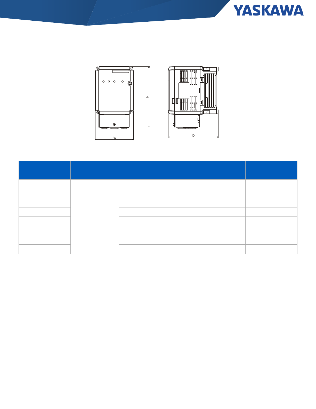
Section: GA800 Drives \ Dimensions
Dimensions
Figure 2: Models 2056, 4031, 4038 Figure 3: Models 2257, 2313, 4208 - 4302
Additional Information
Frame 1 - Models 2004 - 2012 4002 - 4005 Frame 1.5 - Models 2018 - 2042, 4007 - 4023
Frame 2 - Models 2056, 4031 - 4038 Frame 3 - Models 2070 - 2082, 4044
Frame 3.5 - Model 4060 Frame 4 - Models 2110, 4075
Frame 6 - Models 2138, 4084 - 4103 Frame 7 - Models 2169 - 2211, 4140 - 4168
Frame 9 - Models 2257 - 2113, 4208 - 4302 Frame 10 - Models 2360 - 2415, 4371 - 414
Frame 11 - Models 4477 - 4720
GA800 Selection Guide SL.GA800.01, Yaskawa America, Inc. 7

Section: GA800 Drives \ Dimensions
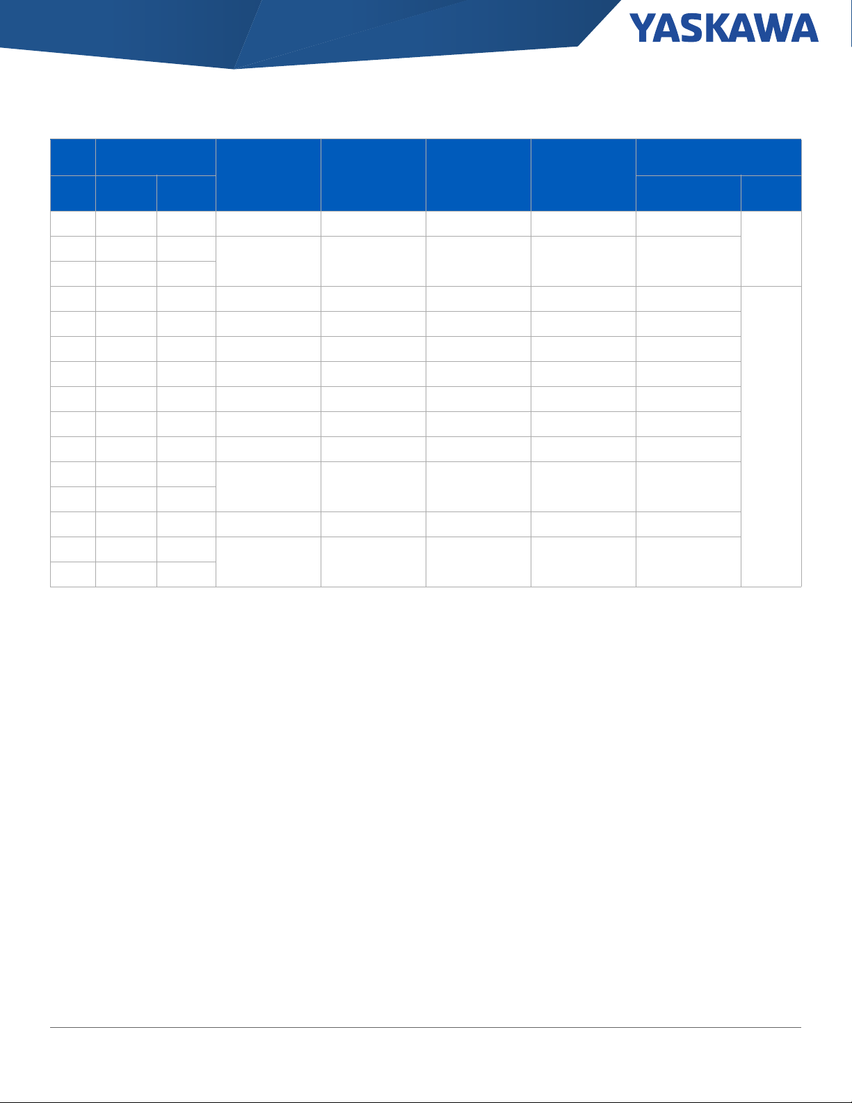
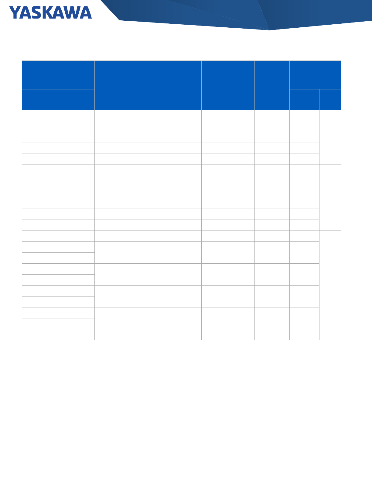
Table 3: Frame Size and Approximate Dimensions
Power Output (HP) 240 V Drives 480 V Drives Approximate Dimensions in (mm)
Normal
Duty
(ND)
1.0 0.75 2004ABM 0.2 3.5 1 4002ABM 2.1 1.8 1 1
1.5 1 2006ABM 6 5 1 - - - -
2 1.5 2008ABM 8 6.9 1 4004ABM 4.1 3.4 1
3 2 2010ABM 9.6 8 1 4005ABM 5.4 4.8 1
4 3 2012ABM 12.2 11 1 4007ABM 7.1 5.5 1.5
5 4 2018ABM 17.5 14 1.5 4009ABM 8.9 7.2 1.5
7.5 5 2021ABM 21 17.5 1.5 4012ABM 11.9 9.2 1.5
10 7.5 2030ABM 30 25 1.5 4018ABM 17.5 14.8 1.5
15 10 2042ABM 42 33 1.5 4023ABM 23.4 18 1.5
20 15 2056ABM 56 47 2 4031ABM 31 24 2
25 20 2070ABM 70 60 3 4038ABM 38 31 2
30 25 2082ABM 82 75 3 4044ABM 44 39 3
40 30 2110ABM 110 88 4 4060ABM 59.6 45 3.5
50 40 2138ABM 138 115 6 4075ABM 74.9 60 4
60 50 2169ABM 169 145 7 4089ABM 89.2 75 6
75 60 2211ABM 211 180 7 4103ABM 103 91 6
100 75 2257ABM 257 215 9 4140ABM 140 112 7
125 100 2313ABM 313 283 9 4168ABM 168 150 7
150 125 2360ABM 360 346 10 4208ABM 208 180 9
150 150 2415ABM 415 415 10 - - - -
200 150
250 200 4302ABM 302 260 9
300 250 4371ABM 371 304 10
350 300 4414ABM 414 371 10
400 350 4477ABM 477 414 11
450 400 4568ABM 568 477 11
500 450 4605ABM 675 605 11
600 500 4720ABM 720 605 11
Heavy
Duty
(HD)
Catalog
Code
GA80U. .
Output Amps
Frame
ND HD ND HD
N/A
Catalog
Code
GA80U . .
4250ABM 250 216 9
Output Amps
Frame Frame Height Width Depth
1.5
3.5
10
11
10.2
(260)
10.2
(260)
11.8
2
(300)
13.8
3
(350)
13.8
(350)
15.7
4
(400)
17.7
6
(450)
21.4
7
(543)
27.6
9
(700)
31.5
(800)
44.72
(1136)
5.51
(140)
5.51
(140)
7.09
(180)
8.66
(220)
8.66
(220)
9.45
(240)
10.0
(255)
10.4
(264)
12.3
(312)
17.3
(440)
20.1
(510)
6.93
(176)
8.31
(211)
7.95
(202)
8.94
(227)
9.69
(246)
11.0
(280)
11.0
(280)
13.2
(335)
16.5
(420)
18.6
(472)
18.9
(480)
8 Yaskawa America, Inc., GA800 Selection Guide SL.GA800.01

Section: GA800 Drives \ Drive Specifications
Drive Specifications
Item Specification
Overload Capacity 150 % for 60 seconds. (HD), 110 % for 60 seconds. (ND)
Output Frequency 0 to 590 Hz
Control Methods
Motor Types
Protective Design Types
Ambient Operating Temperature
Humidity 95 % Relative Humidity or less in a non-condensing environment
Global Certifications UL, CSA, CE, RCM, RoHS
Functional Safety Safe Torque Off, SIL3 according to IEC 62061, PLe according to ISO 13849-1
Standard I/O
I/O Expansion (optional)
Feedback (optional)
Network Communication
Speed Control Range
Speed Control Accuracy 0.02 %: Closed Loop Vector; 0. 2%: Open Loop Vector
Speed Response
Function Block Diagrams Up to 200 connections, 500 µs program scan time
Open and Closed Loop Vector
Open and Closed Loop V/f
Induction
Surface Permanent Magnet
Interior Permanent Magnet
Synchronous Reluctance
IP20 (Type 1 kit available)
Flange (Type 12 backside)
-10 to +50 °C (IP20 and flange types)
-10 to +40 °C (with Type1 kit)
Up to +60 °C (with derate)
(8) multi-function digital inputs (24 Vdc)
(3) multi-function analog inputs (0 +/- 10 Vdc, 4-20 mA)
(1) multi-function pulse inputs
(2) Safe Torque Off inputs
(1) fault relay output (form C)
(3) multi-function relay outputs (form A)
(2) multi-function analog output (0 +/- 10 Vdc, 4-20 mA)
(1) multi-function pulse output
(3) Analog Inputs -10 to +10 V, 13 bit plus sign, 4 to 20 mA
(16) Digital Inputs
(2) Analog Outputs (-10 to +10 V, 11 bit magnitude)
(8) Digital Outputs (6 transistor, 2 relay)
Incremental
Absolute (Stegmann, Heidenhain, Resolver)
Standard: Modbus RTU, RS-485, 115 kbps
Optional: EtherNet/IP, DeviceNet, Modbus TCP/IP, PROFINET, PROFIBUS-DP
1500:1 Closed Loop Vector (IM and PM Motors)
200:1 Open Loop Vector (IM Motors)
100:1 Open Loop Vector (PM Motors)
50 Hz: Closed Loop Vector (Induction Motors); 250 Hz: Closed Loop Vector (PM Motors)
20 Hz: Open Loop Vector (Induction Motors); 40 Hz: Open Loop Vector (PM Motors)
GA800 Selection Guide SL.GA800.01, Yaskawa America, Inc. 9

Section: Control and Feedback Options \ I/O Adapters
Control and Feedback Options
Control Options - These cards and devices add control functionality to the standard drive. Items are shipped loose, unmounted.
Additional Information
Network Communications I/O Adapters
Feedback Encoders
I/O Adapters
Option Purpose Part Number
Analog Input (provides 3 additional inputs)
Digital Input (provides 16 additional inputs)
120 V Digital Interface (converts existing inputs)
Analog Output (provides 2 additional outputs)
Digital Output (provides 8 additional outputs)
Motor Feedback
Option Purpose Part Number
Open Collector
Line Driver
Provides 3 high resolution (13-bit signed) analog inputs. These inputs are configurable for
0 - 10 Vdc, -10 Vdc to +10 Vdc, or 4 - 20 mA, and can be combined with the drive’s
standard analog inputs.
Provides an additional 16 digital inputs which can be programmed individually
(multi-function) or used as a binary-coded decimal (BCD) speed reference, configurable as
2, 3, or 4 digit BCD.
Mounts directly to the control terminal block on the drive and allows the use of 120 Vac
control logic circuits to produce multi-function control input signals for the drive. Used for
digital inputs S1 to S8.
Provides 2 signals for remote metering of any two of the drive's "U1" monitors. Additive to
the two standard analog outputs. Signal level: 0 to +/- 10 Vdc (20 kOhm).
Provides 8 additional digital outputs for use in monitoring the status outputs of the drive.
Signal levels: 6 channels PHC (48 Vdc, 50 mA maximum) and 2 channels of Form A (250
Vac at 1 A or less, 30 Vdc at 1 A or less). Shared Common.
This option provides velocity and direction feedback from an encoder. This is primarily used
for motor speed feedback in closed loop flux vector control. A 24 DC buffered output (open
collector) is also included. 32 kHz maximum input frequency.
Provides velocity and direction feedback from an encoder. Primarily used for motor speed
feedback in closed loop flux vector control. A 5 Vdc buffered output is also included. Signal
levels: 5 or 12 Vdc differential line driver with compliments, maximum input frequency of 300
kHz, phases A and B (Z required with some custom software).
AI-A3
DI-A3
DI-101
AO-A3
DO-A3
PG-B3
PG-X3
10 Yaskawa America, Inc., GA800 Selection Guide SL.GA800.01

Section: Control and Feedback Options \ Motor Feedback
Option Purpose Part Number
This card reads a maximum input frequency from the encoder of 20 kHz. The card allows
Absolute Encoder
Resolver
the user to connect a rotary encoder, either EnDat2.1/01 or EnDat2.2/01 by HEIDENHAIN
for motor speed feedback to the drive and take advantage of the Closed Loop Vector for PM
Motors control mode.
This card reads a maximum input frequency from the encoder of 20 kHz. The card allows
the user to connect a rotary encoder, either EnDat2.1/01 or EnDat2.2/01 by HEIDENHAIN
for motor speed feedback to the drive and take advantage of the Closed Loop Vector for PM
Motors control mode.
PG-F3
PG-RT3
GA800 Selection Guide SL.GA800.01, Yaskawa America, Inc. 11

Section: Control and Feedback Options \ Network Communication Options
Network Communication Options
These cards, cables, and devices add control functionality to the standard drive. Items are shipped loose and unmounted.
Option Purpose Part Number
EtherNet/IP
EtherNet/IP Dual Port SI-EN3D
PROFINET PI compliant option cards to connect to a PROFINET network. SI-EP3
Modbus TCP Simple and effective solution to connect the drive to a Modbus TCP/IP network. SI-EM3
Modbus TCP Dual Port Simple and effective solution to connect the drive to a Modbus TCP/IP network. SI-EM3D
EtherCAT Option cards to turn the drive into an EtherCAT slave on the network. SI-ES3
DeviceNet ODVA compliant option cards to connect to a DeviceNet network. SI-N3
PROFIBUS-DP PI compliant option cards to connect to a PROFIBUS-DP network. SI-P3
CANopen CANopen is a CAN-based communication system. SI-C3
CC-Link
BACnet MSTP BACnet is a data communications protocol for Building Automation and Control Networks. SI-B3
APOGEE/METASYS
LONWORKS LONWOKRS provides building automation communication capabilities. SI-W3
MECHATROLINK II
MECHATROLINK III
ODVA compliant option cards to connect to Ethernet/IP.
CC-Link is an open industrial network protocol that enables devices from different
manufacturers to communicate.
APOGEE/METASYS is a multi-portocol card that provides communications between
different systems and devices.
Option cards to turn the drive into a M-II node and connect to a high-speed
MECHATROLINK-II network.
Option cards to turn the drive into a M-III node and connect to a high-speed
MECHATROLINK-III network.
SI-EN3
SI-C3
SI-J3
SI-T3
SI-ET3
12 Yaskawa America, Inc., GA800 Selection Guide SL.GA800.01

Section: Keypads, Accessories, and Cables \
Keypads, Accessories, and Cables
Additional Information
Keypads and Cables
Table 4: Keypads
Part Number Description
JVOP-KPLCC04MBB LCD Keypad with Bluetooth
LCD Keypad with Bluetooth
Table 5: Remote Mount Adapters
Part Number Description
900-192-933-001 Type 1 Keypad Panel Mount Kit A (brackets have tapped holes for use with screws)
900-192-933-002 Type 1 Keypad Panel Mount Kit B (brackets have untapped holes for use with panel studs)
900-239-230-001 Type 12/3R Keypad Panel Mount (with embedded studs)
-001 Type 1 Screw Mount -002 Type 1 Stud Mount Type 12/3R Mount (with embedded studs)
GA800 Selection Guide SL.GA800.01, Yaskawa America, Inc. 13

Section: Keypads, Accessories, and Cables \
Table 6: Cables
Part Number Description
UWR0051 Keypad Remote Mount Cable - 1 Meter
UWR0052 Keypad Remote Mount Cable - 3 Meter
UWR01258 USB Cable for PC to Drive Communication - 3 Meter
Table 7: Android Mobile Device Interface Cables (for connecting Android device to USB port on drive)
Part Number Description
UWR01516-B USB Mini-B to USB Micro-B. On-The-Go (OTG) compatible, 2-meter length.
UWR01516-C USB Mini-B to USB Type-C. On-The-Go (OTG) compatible, 2-meter length.
P# UWR01516-B - USB Mini-B to USB Micro-B P# UWR01516-C - USB Mini-B to USB Type-C
14 Yaskawa America, Inc., GA800 Selection Guide SL.GA800.01

Section: Enclosure Adapters and Kits \
Enclosure Adapters and Kits
These adapters are for mounting the standard IP20 drives directly to a wall, a machine in a clean environment (Type 1), or inside a Type 1
enclosure with external heatsink. The Type 1 Adapters convert an Open Chassis Drive (IP20) to an enclosed wall-mounted drive (Type 1). The
A1000 to GA800 adapters allow a GA800 to mount where an A1000 was previously mounted.
Type 1 Adapter External Heatsink Adapter A1000 to GA800 Adapters
Additional Information
Type 1 Adapter Manual
Table 8: 240 Volt Drive Mounting Adapters
Catalog Code
GA80U . .
2004ABM
2006ABM
2008ABM
2010ABM
2012ABM
2018ABM
2021ABM
2030ABM
2042ABM
2056ABM 900-192-121-002 900-193-209-002 900-195-081-002
2070ABM 900-192-121-003
2082ABM 900-192-121-004
2110ABM 900-192-121-005
2138ABM 900-192-121-006
2169ABM 900-192-121-007
2211ABM 900-192-121-008
2257ABM
2313ABM
2360ABM
2415ABM
Type 1 Adapters
Part Number Part Number Part Number Part Number
900-192-121-001
900-192-121-009
900-192-121-010
Internal Fuses (Bussman FWH Series)
for Type 1 Adapters
Not Available
External Heatsink Adapter
900-193-209-001 900-195-081-001
900-193-209-003
Included as standard
(see instructions)
Drive Adapters
(A1000 to GA800)
Not Available
GA800 Selection Guide SL.GA800.01, Yaskawa America, Inc. 15

Section: Enclosure Adapters and Kits \
Table 9: 480 Volt Drive Mounting Adapters
Catalog Code
GA80U . .
4002ABM
4004ABM
4005ABM
4007ABM
4009ABM
4012ABM
4018ABM
4023ABM
4031ABM
4038ABM
4044ABM
4060ABM
4075ABM 900-192-121-005
4089ABM
4103ABM
4140ABM
4168ABM
4208ABM
4302ABM
4371ABM
4414ABM UFU000048
4477ABM
4568ABM
4605ABM
4720ABM
Type 1 Adapters
Part Number Part Number Part Number Part Number
900-192-121-001
900-192-121-002 900-193-209-002 900-195-081-002
900-192-121-003 900-193-209-003
900-192-121-006
900-192-121-007
900-192-121-0094250ABM
UUX001700
UUX001701
Internal Fuses (Bussman FWH Series)
for Type 1 Adapters
Not
Available
UFU000047
UFU000049
UFU000050
1 2
External Heatsink
Adapter
900-193-209-001 900-195-081-001
Included as standard
(see instructions)
Drive Adapters
(A1000 to GA800)
Not Available
1. Type 1 Adapters for 4371 and larger are input fuse ready. UL requires Bussman FWH series semiconductor fuses to be installed within the Type 1 Adapter
on these models.
2. Fuses sold individually. A quantity of three are required per drive.
16 Yaskawa America, Inc., GA800 Selection Guide SL.GA800.01

Section: Power Options \
Power Options
Power options are add on devices that can be used to help increase power factor, improve harmonics, and dissipate regenerative energy.
Name Purpose
• Improves the drive input power factor.
• Prevents damage to the drive when the power supply capacity is large. Only use this option when the
DC Bus Reactor
AC Reactor
power supply capacity is more than 600 kVA.
• Decreases harmonic current
• Improves the power supply total power factor.
• Improves the drive input power factor.
• Prevents damage to the drive when the power supply capacity is large. Only use this option when the
power supply capacity is more than 600 kVA.
• Decreases harmonic current
• Improves the power supply total power factor.
3% Braking Resistor
10% Braking Resistor Unit
Braking Unit Use with a braking resistor unit to decrease motor deceleration times.
R1000
Single Phase Converter
Decreases the regenerative energy of the motor and decrease the deceleration time (Duty cycle of 3%
ED). An installation attachment is required.
Decreases the regenerative energy of the motor and decrease the deceleration time (Duty cycle of 10%
ED). The unit contains a thermal overload relay.
The R1000 regenerative module is used to divert energy generated by the motor back onto the line for
use by other loads. The energy is directed back onto the line by taking DC voltage from the drive running
the motor and converting it into a three-phase AC voltage waveform.
The Single Phase Converter is used in single-phase to three-phase conversion applications to eliminate
drive derating. The Single Phase Converter significantly reduces stresses on the power grid with near
unity power factor and less than 10% iTHD.
Additional Information
GA800 Power Options
GA800 Selection Guide SL.GA800.01, Yaskawa America, Inc. 17

Section: Power Options \ DC Bus Reactors
DC Bus Reactors
Use a DC Bus Reactor on the DC bus terminals of a drive to reduce the effect of line-side transients and input current total harmonic
distortion (THD). Large HP drives include a 3% bus impedance as standard. The DC bus reactor is available loose in a separate Type 1
enclosure.
Table 10: 240 Volt DC Bus Reactors
HP
Catalog Code GA80U
Normal
Duty
. .
Heavy
Duty
Open Type
Part Number
3% DC Bus Reactor 5% DC Bus Reactor
Enclosed Type 1
Part Number
Amps
Inductance
(mH)
Open Type
Part Number
Enclosed Type 1
Part Number
Amps
Inductance
(mH)
0.5 2004 . . . 2004 . . . URX000036 URX000207 2 10 URX000037 URX000217 2 15
0.75 2004 . . . 2004 . . . 05P00608-3007 URX000208 4 5 URX000041 URX000207 4 12
1 2006 . . . 2006 . . . 05P00608-3007 URX000208 4 5 URX000041 URX000207 4 12
1.5 2006 . . . 2008 . . . 05P00620-0110 URX000257 9 3.22 05P00620-0111 URX000208 9 7.5
2 2008 . . . 2010 . . . 05P00620-0110 URX000257 9 3.22 05P00620-0111 URX000208 9 7.5
3 2010 . . . 2012 . . . URX000371 URX000258 12 2.1 05P00652-0213 URX000209 12 4
4 2012 . . . 2018 . . . 05P00620-0115 URX000259 18 1.375 URX000048 URX000210 18 2.75
5 2018 . . . 2021 . . . 05P00620-0115 URX000259 18 1.375 URX000048 URX000210 18 2.75
7.5 2021 . . . 2030 . . . URX000051 URX000212 25 1 URX000052 URX000211 25 1.75
10 2030 . . . 2042 . . . 05P00620-0120 URX000261 32 0.85 URX000055 URX000223 32 1.62
15 2042 . . . 2056 . . . URX000059 URX000262 50 0.625 URX000060 URX000222 50 0.97
20 2056 . . . 2070 . . . URX000063 URX000264 62 0.35 URX000064 URX000213 62 0.61
25 2070 . . . 2082 . . . 05P00620-0129 URX000214 80 0.31 URX000069 URX000265 80 0.5
30 2082 . . . - URX000072 URX000266 92 0.2 URX000073 URX000265 92 0.6
40 to 150 Drive models 2110 through 2415 have built-in DC reactors.
18 Yaskawa America, Inc., GA800 Selection Guide SL.GA800.01

Section: Power Options \ DC Bus Reactors
Table 11: 480 Volt DC Bus Reactors
Catalog Code GA80U
HP
0.5 4002 . . . 4002 . . . URX000033 URX000215 1 35 URX000034 URX000215 1 60
0.75 4002 . . . 4002 . . . URX000038 URX000216 2 20 URX000039 URX000215 2 50
1 4002 . . . 4004 . . . URX000038 URX000216 2 20 URX000039 URX000215 2 50
1.5 4004 . . . 4004 . . . 05P00620-0109 URX000217 4 15 URX000042 URX000216 4 25
2 4004 . . . 4005 . . . URX000041 URX000207 4 12 URX000042 URX000216 4 25
3 4005 . . . 4007 . . . URX000044 URX000218 9 11.5 URX000044 URX000218 9 11.5
4 4007 . . . 4009 . . . URX000044 URX000218 9 11.5 URX000044 URX000218 9 11.5
5 4009 . . . 4012 . . . 05P00620-0111 URX000208 9 7.5 URX000044 URX000218 9 11.5
7.5 4012 . . . 4018 . . . 05P00652-0213 URX000209 12 4 URX000046 URX000219 12 6
10 4018 . . . 4023 . . . 05P00652-0216 URX000220 18 3.75 URX000049 URX000260 18 6
15 4023 . . . 4031 . . . URX000052 URX000211 25 1.75 URX000054 URX000224 25 4
20 4031 . . . 4038 . . . URX000055 URX000223 32 1.62 URX000056 URX000221 32 2.68
25 4038 . . . 4044 . . . URX000057 URX000184 40 1 URX000058 URX000225 40 2.5
30 4044 . . . - URX000061 URX000222 50 1.35 URX000062 URX000263 50 2
50 to 600 Drive models 4060 through 4720 have built-in DC reactors.
Normal
Duty
. .
Heavy
Duty
Open Type
Part Number
3% DC Bus Reactor 5% DC Bus Reactor
Enclosed Type 1
Part Number
Amps
Inductance
(mH)
Open Type
Part Number
Enclosed Type 1
Part Number
Amps
Inductance
(mH)
GA800 Selection Guide SL.GA800.01, Yaskawa America, Inc. 19

Section: Power Options \ DC Bus Reactors
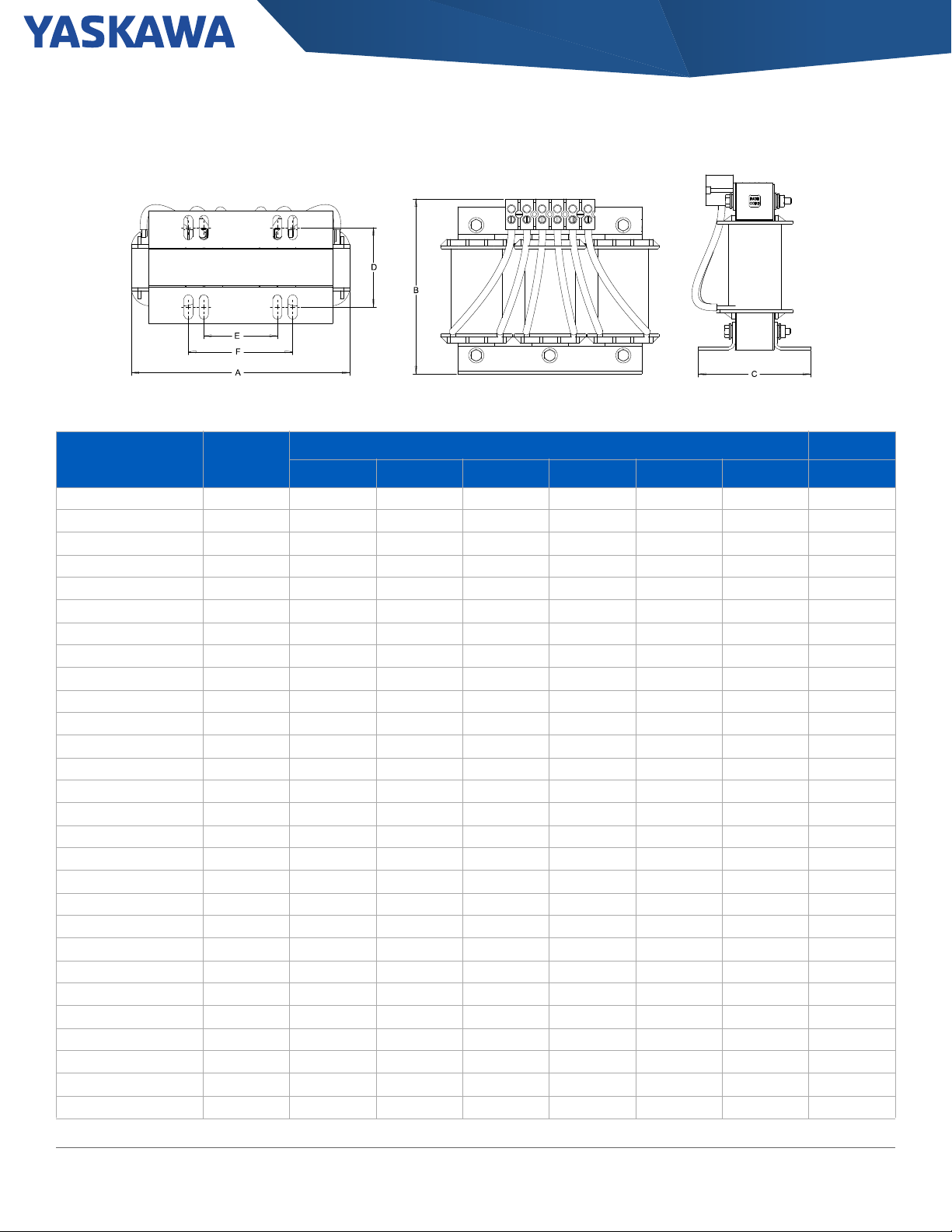
Open Type DC Bus Reactor Dimensions
Figure 4: Figure 5:
Figure 6:
Table 12: Open Type Reactor Dimensions
DC Bus Reactor Figure DC Bus Reactor Figure
05P00608-3007 4 URX000048 5
05P00620-0109 4 URX000049 5
05P00620-0110 4 URX000051 5
05P00620-0111 5 URX000052 5
05P00620-0115 5 URX000054 5
05P00620-0120 5 URX000055 5
05P00620-0129 6 URX000056 5
05P00652-0213 5 URX000057 5
05P00652-0216 5 URX000058 5
URX000033 4 URX000059 5
URX000034 4 URX000060 5
URX000036 4 URX000061 5
URX000037 4 URX000062 6
URX000038 4 URX000063 6
URX000039 4 URX000064 6
URX000041 5 URX000069 6
URX000042 5 URX000072 6
URX000044 5 URX000073 6
URX000046 5 URX000371 5
20 Yaskawa America, Inc., GA800 Selection Guide SL.GA800.01

Section: Power Options \ DC Bus Reactors
«%#$
#55'/$.;*1.'5
5.)43).#(%3
5.)43).#(%3
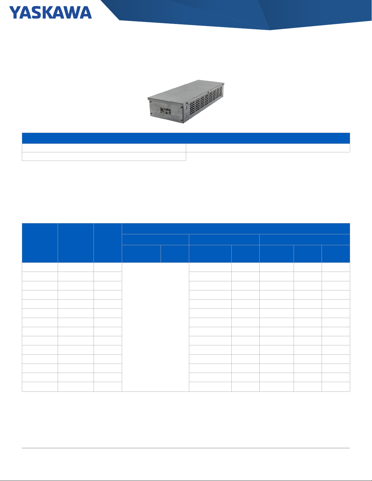
Enclosed DC Reactor Dimensions
Figure 7: CAB-8 Figure 8: CAB-13V
Table 13: Enclosed Type Reactor Dimensions
DC Bus Reactor Figure
URX000207
URX000208
URX000209
URX000210
URX000211
URX000213
URX000215
URX000216
URX000217
URX000218
URX000219
URX000221
URX000222
URX000223
URX000224
URX000225
URX000260
URX000263
URX000265
7
8
7
8
GA800 Selection Guide SL.GA800.01, Yaskawa America, Inc. 21

Section: Power Options \ AC Input Reactors
AC Input Reactors
3% and 5% impedance reactors may be used on either the input or output to reduce the effects of line or load side transients on the drive.
The reactors listed are available loose or in a separate Type 1 enclosure.
Table 14: 240 Volt AC Input Reactors
Catalog Code
HP
0.5 2004 . . . 2004 . . . URX000287 URX000583 1.6 6.9 URX000292 URX000502 2.1 11
0.75 2004 . . . 2004 . . . URX000295 URX000409 3.4 3.2 URX000296 URX000584 3.4 6.8
1 2006 . . . 2006 . . . URX000295 URX000409 3.4 3.2 URX000300 URX000503 4.8 4.8
1.5 2006 . . . 2008 . . . URX000299 URX000410 4.8 2.3 URX000300 URX000503 4.8 4.8
2 2008 . . . 2010 . . . URX000303 URX000411 7.6 1.5 URX000304 URX000504 7.6 3
3 2010 . . . 2012 . . . URX000307 URX000413 11 1 URX000308 URX000414 11 2.1
4 2012 . . . 2018 . . . URX000307 URX000413 11 1 URX000312 URX000416 14 1.6
5 2018 . . . 2021 . . . URX000311 URX000415 14 0.79 URX000316 URX000419 21 1.1
7.5 2021 . . . 2030 . . . URX000315 URX000418 21 0.53 URX000320 URX000421 28 .82
10 2030 . . . 2042 . . . URX000319 URX000420 28 .39 URX000324 URX000423 35 .71
15 2042 . . . 2056 . . . URX000326 URX000424 46 0.3 URX000330 URX000553 55 0.48
20 2056 . . . 2070 . . . URX000332 URX000426 65 0.19 URX000333 URX000554 65 0.36
25 2070 . . . 2082 . . . URX000335 URX000427 83 0.17 URX000336 URX000555 83 0.29
30 2082 . . . - URX000338 URX000428 104 0.12 URX000339 URX000556 104 0.23
30 - 2110 . . . URX000338 URX000428 104 0.12
40 2110 . . . 2138 . . . URX000338 URX000428 104 0.12
50 2138 . . . 2169 . . . URX000341 URX000429 130 0.095
60 2169 . . . 2211 . . . URX000344 URX000430 160 0.08
75 2211 . . . 2257 . . . URX000347 URX000431 200 0.06
100 2257 . . . 2313 . . . URX000350 URX000432 250 0.05
125 2313 . . . 2360 . . . URX000356 URX000434 414 0.033
150 2360 . . . 2415 . . . URX000356 URX000434 414 0.033
GA80U . .
Normal
Duty
Heavy
Duty
Open Type
Part Number
3% Input Reactor 5% Input Reactor
Enclosed Type 1
Part Number
Amps
Inductance
(mH)
Open Type
Part Number
5% input reactor not recommended for these drive sizes
Enclosed Type 1
Part Number
Amps
Inductance
(mH)
22 Yaskawa America, Inc., GA800 Selection Guide SL.GA800.01

Section: Power Options \ AC Input Reactors
Table 15: 480 Volt AC Input Reactors
Catalog Code
HP
0.5 4002 . . . 4002 . . . URX000284 URX000585 1.1 21 URX000286 URX000569 1.1 42
0.75 4002 . . . 4002 . . . URX000288 URX000551 1.6 14 URX000285 URX000570 1.1 33
1 4002 . . . 4004 . . . URX000292 URX000502 2.1 11 URX000289 URX000571 1.6 23
1.5 4004 . . . 4004 . . . URX000301 URX000552 4.8 7.7 URX000293 URX000572 2.1 18
2 4004 . . . 4005 . . . URX000296 URX000584 3.4 6.8 URX000297 URX000573 3.4 11
3 4005 . . . 4007 . . . URX000300 URX000503 4.8 4.8 URX000301 URX000552 4.8 7.7
4 4007 . . . 4009 . . . URX000304 URX000504 7.6 3 URX000306 URX000412 7.6 6
5 4009 . . . 4012 . . . URX000304 URX000504 7.6 3 URX000305 URX000574 7.6 4.8
7.5 4012 . . . 4018 . . . URX000308 URX000414 11 2.1 URX000309 URX000505 11 3.3
10 4018 . . . 4023 . . . URX000312 URX000416 14 1.6 URX000313 URX000417 14 2.6
15 4023 . . . 4031 . . . URX000316 URX000419 21 1.1 URX000317 URX000568 21 1.8
20 4031 . . . 4038 . . . URX000320 URX000421 28 .82 URX000321 URX000575 28 1.3
25 4038 . . . 4044 . . . URX000324 URX000423 35 .71 URX000325 URX000576 35 1.2
30 4044 . . . - URX000327 URX000425 46 0.55 URX000328 URX000577 46 0.98
30 - 4060 . . . URX000327 URX000425 46 0.55
40 4060 . . . 4075 . . . URX000330 URX000553 55 0.48
50 4075 . . . 4089 . . . URX000333 URX000554 65 0.36
60 4089 . . . 4103 . . . URX000336 URX000555 83 0.29
75 4103 . . . 4140 . . . URX000339 URX000556 104 0.23
100 4140 . . . 4168 . . . URX000342 URX000557 130 0.18
125 4168 . . . 4208 . . . URX000345 URX000558 160 0.155
150 4208 . . . 4250 . . . URX000348 URX000559 200 0.115
200 4250 . . . 4302 . . . URX000351 URX000560 250 0.095
250 4302 . . . 4371 . . . URX000354 URX000561 322 0.07
300 4371 . . . 4414 . . . URX000357 URX000562 414 0.066
350 4414 . . . 4477 . . . URX000360 URX000563 515 0.05
400 4477 . . . 4568 . . . URX000360 URX000563 515 0.05
450 4568 . . . 4605 . . . URX000363 URX000564 600 0.04
500 4605 . . . 4720 . . . URX000363 URX000564 600 0.04
600 4720 . . . - URX000366 URX000565 750 0.035
GA80U . .
Normal
Duty
Heavy
Duty
Open Type
PartNumber
3% Input Reactor 5% Input Reactor
Enclosed Type 1
Part Number
Amps
Inductance
(mH)
Open Type
Part Number
5% input reactor not recommended for these drive sizes
Enclosed Type 1
Part Number
Amps Inductance
GA800 Selection Guide SL.GA800.01, Yaskawa America, Inc. 23

Section: Power Options \ AC Output Reactors
AC Output Reactors
Table 16: 240 Volt AC Output Reactors
Catalog Code GA80U . . 3% Output Reactor
HP
Normal Duty Heavy Duty
0.5 2004 . . . 2004 . . . 05P00620-0132 05P00620-0021 4 6.5
0.75 2004 . . . 2004 . . . 05P00620-0017 05P00620-0020 4 3.0
1 2006 . . . 2006 . . . 05P00620-0133 05P00620-0028 8 3.0
1.5 2006 . . . 2008 . . . 05P00620-0133 05P00620-0028 8 3.0
2 2008 . . . 2010 . . . 05P00620-0024 05P00620-0027 8 1.5
3 2010 . . . 2012 . . . 05P00620-0134 05P00620-0032 12 1.25
4 2012 . . . 2018 . . . 05P00620-0134 05P00620-0032 12 1.25
5 2018 . . . 2021 . . . 05P00620-0136 05P00620-0036 18 0.8
7.5 2021 . . . 2030 . . . URX000083 05P00620-0041 25 0.5
10 2030 . . . 2042 . . . 05P00620-0044 05P00620-0046 35 0.4
15 2042 . . . 2056 . . . 05P00620-0140 05P00620-0050 45 0.3
20 2056 . . . 2070 . . . 05P00620-0143 05P00620-0058 80 0.20
25 2070 . . . 2082 . . . 05P00620-0143 05P00620-0058 80 0.20
30 2082 . . . 2110 . . . 05P00620-0143 05P00620-0058 80 0.20
40 2110 . . . 2138 . . . URX000085 URX000204 100 0.15
50 2138 . . . 2169 . . . 05P00620-0064 05P00620-0066 130 0.10
60 2169 . . . 2211 . . . 05P00620-0069 URX000206 160 0.075
75 2211 . . . 2257 . . . 05P00620-0075 05P00620-0077 200 0.055
100 2257 . . . 2313 . . . URX000175 URX000248 250 0.045
125 2313 . . . 2360 . . . 05P00620-0085 URX000249 320 0.040
150 2360 . . . 2415 . . . URX000181 URX000250 400 0.030
150 2415 . . . - URX000181 URX000250 400 0.030
Open Type
Part Number
Enclosed Type 1
Part Number
Amps
Inductance
(mH)
24 Yaskawa America, Inc., GA800 Selection Guide SL.GA800.01

Section: Power Options \ AC Output Reactors
Table 17: 480 Volt AC Output Reactors
Catalog Code GA80U . . 3% Output Reactor
HP
Normal Duty Heavy Duty
0.5 4002 . . . 4002 . . . 05P00620-0014 05P00620-0016 2 20.0
0.75 4002 . . . 4002 . . . 05P00620-0131 05P00620-0015 2 12.0
1 4002 . . . 4004 . . . 05P00620-0131 05P00620-0015 2 12.0
1.5 4004 . . . 4004 . . . 05P00620-0018 05P00620-0022 4 9.0
2 4004 . . . 4005 . . . 05P00620-0132 05P00620-0021 4 6.5
3 4005 . . . 4007 . . . 05P00620-0025 05P00620-0029 8 5.0
4 4007 . . . 4009 . . . 05P00620-0025 05P00620-0029 8 5.0
5 4009 . . . 4012 . . . 05P00620-0133 05P00620-0028 8 3.0
7.5 4012 . . . 4018 . . . 05P00620-0135 05P00620-0033 12 2.5
10 4018 . . . 4023 . . . 05P00620-0137 05P00620-0037 18 1.5
15 4023 . . . 4031 . . . 05P00620-0138 05P00620-0042 25 1.2
20 4031 . . . 4038 . . . 05P00620-0139 05P00620-0047 35 0.8
25 4038 . . . 4044 . . . 05P00620-0139 05P00620-0047 35 0.8
30 4044 . . . 4060 . . . 05P00620-0049 05P00620-0051 45 0.7
40 4060 . . . 4075 . . . 05P00620-0142 05P00620-0055 55 0.50
50 4075 . . . 4089 . . . 05P00620-0144 05P00620-0059 80 0.40
60 4089 . . . 4103 . . . 05P00620-0144 05P00620-0059 80 0.40
75 4103 . . . 4140 . . . 05P00620-0145 05P00620-0062 100 0.30
100 4140 . . . 4168 . . . 05P00620-0013 05P00620-0067 130 0.20
125 4168 . . . 4208 . . . 05P00620-0070 05P00620-0073 160 0.150
150 4208 . . . 4250 . . . URX000586 05P00620-0078 200 0.110
200 4250 . . . 4302 . . . URX000176 05P00620-0083 250 0.090
250 4302 . . . 4371 . . . URX000179 05P00620-0088 320 0.075
300 4371 . . . 4414 . . . URX000182 05P00620-0092 400 0.060
350 4414 . . . 4477 . . . 05P00620-0094 05P00620-0096 500 0.050
400 4477 . . . 4568 . . . 05P00620-0094 05P00620-0096 500 0.050
450 4568 . . . 4605 . . . 05P00620-0098 05P00620-0100 600 0.040
500 4605 . . . 4720 . . . 05P00620-0098 05P00620-0100 600 0.040
600 4720 . . . - 05P00620-0102 05P00620-0104 750 0.029
Open Type
Part Number
Enclosed Type 1
Part Number
Amps Inductance
GA800 Selection Guide SL.GA800.01, Yaskawa America, Inc. 25
Section: Power Options \ AC Open Reactor Dimensions
AC Open Reactor Dimensions
Table 18: AC Open Reactor Dimensions
Open Type Reactor
Part number
05P00620-0013 180 229/9 183/7.2 172/6.8 93/3.66 92/3.63 - 28/62
05P00620-0014 11.3 112/4.4 104/4.1 71/2.8 50/1.98 37/1.44 - 1.8/4
05P00620-0017 14.5 112/4.4 104/4.1 71/2.8 50/1.98 37/1.44 - 1.8/4
05P00620-0018 20 112/4.4 104/4.1 86/3.4 60/2.35 37/1.44 - 2.3/5
05P00620-0024 19.5 152/6.0 122/4.8 76/3.0 53/2.10 51/2.00 - 3.2/7
05P00620-0025 25.3 152/6.0 122/4.8 86/3.4 67/2.62 51/2.00 - 5.0/11
05P00620-0044 49 183/7.2 147/5.8 102/4.0 66/2.60 76/3.00 - 6.4/14
05P00620-0049 62 229/9.0 188/7.4 119/4.7 80/3.16 76/3.00 - 13/28
05P00620-0064 108 229/9.0 179/7.1 118/4.7 80/3.16 76/3.00 - 13/29
05P00620-0069 116 229/9 183/7.2 172/6.8 80/3.16 92/3.63 - 19/42
05P00620-0070 149 274/10.8 277/8.3 152/6 88/3.47 92/3.63 - 23/51
05P00620-0075 124 229/9 191/7.5 185/7.3 106/4.16 92/3.63 - 22/49
05P00620-0080 154 229/9 191/7.5 229/9 106/4.16 92/3.63 - 31/68
05P00620-0085 224 274.3/10.8 213.4/8.4 200.7/7.9 131/5.2 117/4.6 - 36.3/80
05P00620-0088 224 275/11 214/8.5 201/8 131/5.2 117/4.6 - 36/80
05P00620-0090 333 381/15 286/11.3 292/11.5 172/6.76 117/4.60 - 71/155
05P00620-0094 340 366/14.4 292/11.5 292/11.5 172/6.76 117/4.60 - 82/180
05P00620-0098 414 366/14.4 286/11.3 305/12 203/8.00 117/4.60 - 114/250
05P00620-0102 630 366/14.4 292/11.5 318/12.5 204/8.01 183/7.20 - 141/310
05P00620-0131 7.5 112/4.4 104/4.1 71/2.8 50/1.98 37/1.44 - 1.8/4
05P00620-0132 20 112/4.4 104/4.1 71/2.8 50/1.98 37/1.44 - 1.8/4
05P00620-0133 29 152/6.0 122/4.8 76/3.0 53/2.10 51/2.00 - 3.6/8
05P00620-0134 26 152/6.0 127/5.0 84/3.3 53/2.10 51/2.00 - 4.1/9
05P00620-0135 31 152/6.0 127/5.0 84/3.3 53/2.10 51/2.00 - 4.5/10
05P00620-0136 36 152/6.0 135/5.3 81/3.2 54/2.10 51/2.00 - 4.1/9
05P00620-0137 43 152/6.0 135/5.3 89/3.5 63/2.48 51/2.00 - 5.5/12
05P00620-0138 52 183/7.2 147/5.8 89/3.5 60/2.35 76/3.00 - 6.4/14
05P00620-0139 54 183/7.2 147/5.8 102/4.0 70/2.75 76/3.00 - 7.3/16
Watt Loss
A B C D E F kg/lb
Dimensions (mm/in) Weight
26 Yaskawa America, Inc., GA800 Selection Guide SL.GA800.01

Section: Power Options \ AC Open Reactor Dimensions
Open Type Reactor
Part number
05P00620-0140 54 229/9.0 188/7.4 119/4.7 80/3.16 76/3.00 - 10/23
05P00620-0142 67 229/9.0 178/7.0 135/5.3 80/3.16 76/3.00 - 12/27
05P00620-0143 82 229/9 183/7.2 160/6.3 88/3.47 92/3.63 - 20/43
05P00620-0144 86 229/9 183/7.2 165/6.5 88/3.47 92/3.63 - 23/51
05P00620-0145 84 229/9 185/7.3 173/6.8 93/3.66 92/3.63 - 23/51
05P00620-0147 231 274/10.8 216/8.5 229/9 131/5.16 117/4.60 - 48/106
05P00620-0148 264 274/10.8 229/9 254/10 149/5.88 117/4.60 - 57/125
URX000083 48 183/7.2 147/5.8 89/3.5 60/2.35 76/3.00 - 5.0/11
URX000085 94 229/9 185/7.3 165/6.5 88/3.46 92/3.62 - 21/47
URX000175 154 243.8/9.6 177.8/7 205.7/8.1 106/4.2 92/3.63 - 21.3/47
URX000176 231 274.3/10.8 215.9/8.5 193/7.6 131/5.2 117/4.6 - 36.3/80
URX000179 264 274.3/10.8 213.4/8.4 226.1/8.9 149/5.9 117/4.6 - 46.3/102
URX000181 213 280/11 214/8.5 219/8.6 131/5.2 117/4.6 - 38/84
URX000182 571 363.2/14.3 281.9/11.1 238.8/9.4 172/6.8 117/4.6 - 53.5/118
URX000284 7.8 114/4.5 94/3.7 38/1.5 0/0 102/4 - 0.7/1.6
URX000285 10.1 114/4.5 94/3.7 38/1.5 0/0 102/4 - 0.7/1.6
URX000286 11.9 114/4.5 94/3.7 38/1.5 0/0 102/4 - 0.8/1.7
URX000287 6.9 114/4.5 94/3.7 38/1.5 0/0 102/4 - 0.7/1.5
URX000288 10.9 114/4.5 94/3.7 38/1.5 0/0 102/4 - 0.7/1.6
URX000289 15 114/4.5 94/3.7 38/1.5 0/0 102/4 - 0.7/1.6
URX000292 14.3 114/4.5 94/3.7 38/1.5 0/0 102/4 - 0.7/1.6
URX000293 19.6 114/4.5 94/3.7 38/1.5 0/0 102/4 - 0.8/1.7
URX000295 12.3 114/4.5 94/3.7 38/1.5 0/0 102/4 - 0.7/1.6
URX000296 19.6 114/4.5 94/3.7 38/1.5 0/0 102/4 - 0.7/1.6
URX000297 26.5 112/4.4 127/5 71/2.8 51/2 36/1.4 - 1.2/2.7
URX000299 13.8 114/4.5 94/3.7 38/1.5 0/0 102/4 - 0.8/1.7
URX000300 23 114/4.5 94/3.7 38/1.5 0/0 102/4 - 0.8/1.8
URX000301 37.5 112/4.4 127/5 71/2.8 51/2 36/1.4 - 1.3/2.8
URX000303 19.2 114/4.5 94/3.7 38/1.5 0/0 102/4 - 0.8/1.8
URX000304 37.2 112/4.4 127/5 71/2.8 51/2 36/1.4 - 1.3/2.8
URX000305 47.8 112/4.4 127/5 79/3.1 53/2.1 36/1.4 - 1.9/4.1
URX000306 53.8 112/4.4 127/5 79/3.1 53/2.1 36/1.4 - 1.9/4.2
URX000307 26.8 112/4.4 127/5 71/2.8 51/2 36/1.4 - 1.2/2.7
URX000308 40.9 112/4.4 127/5 79/3.1 53/2.1 36/1.4 - 1.9/4.2
URX000309 54.4 112/4.4 127/5 89/3.5 66/2.6 36/1.4 - 2.4/5.3
URX000311 32.7 112/4.4 135/5.3 71/2.8 51/2 36/1.4 - 1.3/2.8
URX000312 48.2 112/4.4 127/5 79/3.1 53/2.1 36/1.4 - 2/4.3
URX000313 60.6 152/6 147/5.8 74/2.9 53/2.1 51/2 - 3.2/7.1
URX000315 38.3 112/4.4 135/5.3 84/3.3 61/2.4 36/1.4 - 1.9/4.2
URX000316 57.4 152/6 155/6.1 74/2.9 0/0 102/4 - 3.3/7.2
Watt Loss
A B C D E F kg/lb
Dimensions (mm/in) Weight
GA800 Selection Guide SL.GA800.01, Yaskawa America, Inc. 27

Section: Power Options \ AC Open Reactor Dimensions
Open Type Reactor
Part number
URX000317 73.5 152/6 155/6.1 84/3.3 0/0 102/4 - 4.5/10
URX000319 48.2 112/4.4 135/5.3 89/3.5 0/0 102/4 - 2.3/5.1
URX000320 66.8 152/6 155/6.1 84/3.3 0/0 102/4 - 4.3/9.5
URX000321 93.8 152/6 155/6.1 84/3.3 0/0 102/4 - 4.7/10.4
URX000324 102 183/7.2 152/6 95/3.8 0/0 102/4 - 5.9/13
URX000325 121 183/7.2 152/6 109/4.3 0/0 102/4 - 8.2/18
URX000326 77 183/7.2 152/6 95/3.75 0/0 102/4 - 5.9/13
URX000327 99 183/7.2 152/6 109/4.3 0/0 102/4 - 7.7/17
URX000328 179 229/9 211/8.3 122/4.8 0/0 102/4 108/4.26 10.9/24
URX000330 109 229/9 211/8.3 130/5.1 0/0 102/4 - 9.1/20
URX000332 87 183/7.2 152/6 102/4 0/0 102/4 - 8.2/18
URX000333 105 183/7.2 152/6 109/4.3 0/0 102/4 - 43395
URX000335 119 183/7.2 152/6 109/4.3 0/0 102/4 - 8.6/19
URX000336 155 229/9 178/7 165/6.5 0/0 102/4 108/4.26 11.8/26
URX000338 94 183/7.2 152/6 165/6.5 70/2.75 76/3 108/4.26 43395
URX000339 200 229/9 178/7 178/7 82/3.24 76/3 108/4.26 12.7/28
URX000341 132 235/9.25 191/7.5 171/6.75 83/3.25 76/3 108/4.26 11.8/26
URX000342 152 235/9.25 191/7.5 171/6.75 95/3.75 76/3 108/4.26 16.8/37
URX000344 110 235/9.25 191/7.5 171/6.75 95/3.75 76/3 108/4.26 15.4/34
URX000345 195 235/9.25 191/7.5 210/8.25 121/4.75 76/3 108/4.26 22.2/49
URX000347 159 235/9.25 191/7.5 178/7 10/0.375 76/3 108/4.26 15.4/34
URX000348 224 235/9.25 191/7.5 210/8.25 121/4.75 76/3 108/4.26 22.2/49
URX000350 275 235/9.25 191/7.5 191/7.5 95/3.75 76/3 108/4.26 15.9/35
URX000351 284 235/9.25 191/7.5 216/8.5 121/4.75 76/3 108/4.26 24.9/55
URX000354 383 274/10.8 222/8.75 216/8.5 136/5.37 92/3.63 142/5.58 34.5/76
URX000356 333 229/9 222/8.75 241/9.5 136/5.37 92/3.63 142/5.58 35.4/78
URX000357 531 229/9 222/8.75 292/11.5 174/6.87 92/3.63 142/5.58 44.4/98
URX000360 496 229/9 222/8.75 305/12 162/6.37 92/3.63 142/5.58 53.5/118
URX000363 747 366/14.4 292/11.5 318/12.5 206/8.12 117/4.6 150/5.9 65.3/144
URX000366 838 366/14.4 292/11.5 318/12.5 194/7.62 117/4.6 183/7.2 81.2/179
URX000586 168 229/9 191/7.5 211/8.3 112/4.41 92/3.63 - 31/67
URX000587 224 274/10.8 229/9 277/8.3 131/5.16 117/4.60 - 50/110
URX000588 231 274/10.8 254/10 254/10.0 131/5.16 117/4.60 - 46/100
Watt Loss
A B C D E F kg/lb
Dimensions (mm/in) Weight
28 Yaskawa America, Inc., GA800 Selection Guide SL.GA800.01

Section: Power Options \ AC Enclosed Reactor Dimensions
«%#$
#55'/$.;*1.'5
5.)43).#(%3
5.)43).#(%3
8'06'&2#0'.
(4106$#%-
5.)43).#(%3
5.)43).#(%3
AC Enclosed Reactor Dimensions
Figure 9: CAB-8 Figure 10: CAB-13V
Figure 11: CAB-17V Figure 12: CAB-26C
GA800 Selection Guide SL.GA800.01, Yaskawa America, Inc. 29

Section: Power Options \ AC Enclosed Reactor Dimensions
5.)43).#(%3
Figure 13: CAB-30B
30 Yaskawa America, Inc., GA800 Selection Guide SL.GA800.01

Section: Power Options \ AC Enclosed Reactor Dimensions
Table 19: AC Input/Output Enclosed Reactor Specifications
Enclosed Type 1 Reactor
Part number
05P00620-0015
05P00620-0016 5/11
05P00620-0020 5/11
05P00620-0021 5/11
05P00620-0022 5/12
05P00620-0027 6/14
05P00620-0028 7/15
05P00620-0029 8/18
05P00620-0032 7/16
05P00620-0033 8/17
05P00620-0036 7/16
05P00620-0037 9/19
05P00620-0041
05P00620-0042 15/32
05P00620-0046 15/32
05P00620-0047 16/34
05P00620-0050 19/41
05P00620-0051 21/46
05P00620-0055 20/45
05P00620-0058 20/43
05P00620-0059 23/51
05P00620-0062 32/51
05P00620-0066 21/47
05P00620-0067 28/61
05P00620-0073 31/68
05P00620-0077 25/56
05P00620-0078 33/72
05P00620-0083
05P00620-0088 59/129
05P00620-0092 66/145
05P00620-0096
05P00620-0100 145/319
05P00620-0104 13 158/349
URX000204
URX000206 27/59
URX000248 30/65
URX000249
URX000250 50/111
URX000409
URX000410 3.9/8.7
Cabinet Reference (Figure)
9
10
11
12
10
11
9
Weight
kg/lb
5/11
13/23
49/107
119/262
21/47
49/107
3.9/8.6
GA800 Selection Guide SL.GA800.01, Yaskawa America, Inc. 31

Section: Power Options \ AC Enclosed Reactor Dimensions
Enclosed Type 1 Reactor
Part number
URX000411
URX000412 5.1/11.2
URX000413 4.4/9.7
URX000414 5.1/11.2
URX000415 4.4/9.8
URX000416 5.1/11.3
URX000417 6.4/14.1
URX000418
URX000419 11/25.2
URX000420 10/23.1
URX000421 12/27.5
URX000423 14/31
URX000424 14/31
URX000425 16/35
URX000426 16/36
URX000427 17/37
URX000428 14/40
URX000429 20/44
URX000430 24/52
URX000431
URX000432 28/62
URX000434 12 101/222
URX000502
URX000503 4.0/8.8
URX000504 4.4/9.8
URX000505 5.6/12.3
URX000551 3.9/8.6
URX000552 4.4/9.8
URX000553
URX000554 18/40
URX000555 20/44
URX000556 21/46
URX000557 25/55
URX000558 30/67
URX000559
URX000560 37/82
URX000561
URX000562 110/242
URX000563 119/262
URX000564 131/288
Cabinet Reference (Figure)
9
10
11
9
10
11
12
Weight
kg/lb
4.0/8.8
10/22.2
28/61
3.9/8.6
17/38
34/76
100/220
32 Yaskawa America, Inc., GA800 Selection Guide SL.GA800.01

Section: Power Options \ AC Enclosed Reactor Dimensions
Enclosed Type 1 Reactor
Part number
URX000565 12 147/323
URX000568 10 13/28
URX000569
URX000570 3.9/8.6
URX000571 3.9/8.6
URX000572 3.9/8.7
URX000573 4.4/9.7
URX000574 5/11.1
URX000575
URX000576 16/36
URX000577 19/42
URX000583
URX000584 3.9/8.6
URX000585 3.9/8.6
Cabinet Reference (Figure)
9
10
9
Weight
kg/lb
3.9/8.7
13/28.4
3.9/8.5
GA800 Selection Guide SL.GA800.01, Yaskawa America, Inc. 33
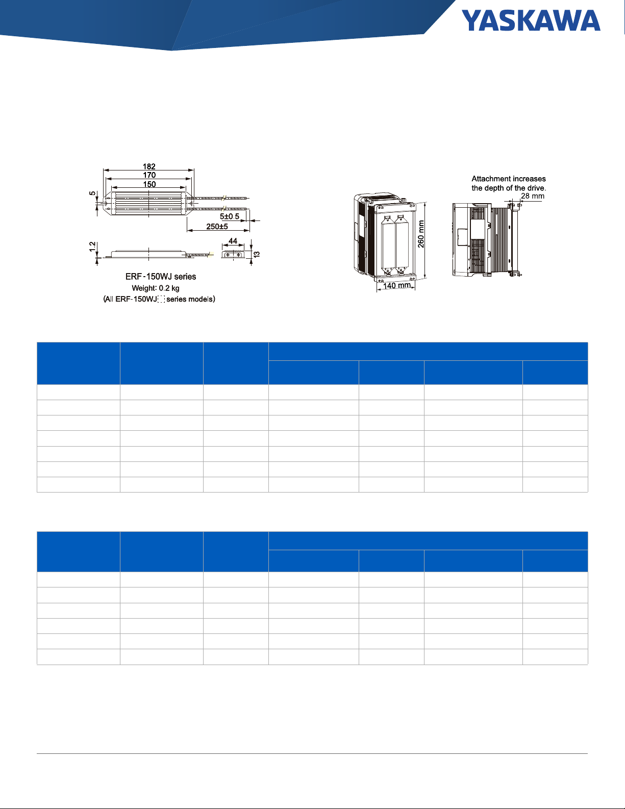
Section: Power Options \ Dynamic Braking Options
Dynamic Braking Options
Additional Information
Braking Resistor Specifications Braking Resistor Drawings
Braking Connection Diagrams
10% Dynamic Braking Options
Dynamic Braking Resistor, 10% Duty Cycle - are rated for 10% duty cycle over a 100 second interval. The resistors will achieve a minimum
150% peak braking torque for heavy duty horsepower ratings and a minimum of 100% peak braking power for normal duty horsepower
ratings. These resistors are designed for separate panel mounting.
Table 20: 240 Volt 10% Dynamic Braking Options
10% Dynamic Braking Option (maximum 10 second on-time)
Catalog
Normal Duty HP Heavy Duty HP
0.75 0.75 2004. . .
1.5 1 2006. . . URS000276 1 125 101 GCE1
2 1.5 2008. . . URS000277 1 85 151 GCE1
3 2 2010. . . URS000278 1 63 201 GCE1
4 3 2012. . . URS000279 1 42 302 GCE1
5 4 2018. . . URS000368 1 34 373 GCE1
7.5 5 2021. . . URS000280 1 25 504 GCE2
10 7.5 2030. . . URS000269 1 19 671 GCE2
15 10 2042. . . URS000282 1 12.6 1007 GCE3
20 15 2056. . . URS000369 1 9.2 1492 GCE4
25 20 2070. . . URS000370 1 6.9 1865 GCE6
30 25
40 30 2110. . . URS000372 1 4.6 2984 GCE6
50 40
Code
GA80U . .
2082. . .
2138. . .
1
1
Transistor Module Resistor Resistor Specifications
Part Number Quantity Part Number Quantity Resistance Watts Enclosure
URS000275 1 170 76 GCE1
Built-in
URS000371 1 6.6 2238 GCE6
URS000373 1 4.2 3730 GCE9
34 Yaskawa America, Inc., GA800 Selection Guide SL.GA800.01

Section: Power Options \ 10% Dynamic Braking Options
10% Dynamic Braking Option (maximum 10 second on-time)
Catalog
Normal Duty HP Heavy Duty HP
60 50 2169. . . CDBR-21100D 1 URS000100 1 2.1 5250 GCE9
75 60 2211. . . CDBR-21100D 1 URS000100 1 2.1 5250 GCE9
100 75 2257. . . CDBR-21100D 1 URS000096 1 1.6 6553 GCE12
125 100 2313. . .
150 125 2360. . .
150 150 2415. . . CDBR-21100D 2 URS000097 1 2 x 1.6 2 x 6553 GCE24
1. The resistor used for models 2082 & 2138 achieve a minimum of 125% peak braking torque for heavy duty horsepower ratings and a minimum of 100%
peak braking power for normal duty horsepower ratings.
Code
GA80U . .
Transistor Module Resistor Resistor Specifications
Part Number Quantity Part Number Quantity Resistance Watts Enclosure
CDBR-21100D 1 URS000096 1 1.6 6554 GCE12
CDBR-20220D 1 URS000128 1 6.8 1740 GCE6
CDBR-21100D 1 URS000096 1 1.6 6554 GCE12
CDBR-20220D 2 URS000129 1 2 x 6.8 2 x 1740 GCE2
Table 21: 480 Volt 10% Dynamic Braking Options
10% Dynamic Braking Option (maximum 10 second on-time)
Normal Duty HP Heavy Duty HP
1 0.75 4002. . .
2 1.5 4004. . . URS000241 1 375 134 GCE1
3 2 4005. . . URS000253 1 250 201 GCE1
4 3 4007. . . URS000254 1 170 302 GCE1
5 4 4009. . . URS000375 1 138 373 GCE1
7.5 5 4012. . . URS000255 1 100 504 GCE2
10 7.5 4018. . . URS000256 1 67 755 GCE3
15 10 4023. . . URS000257 1 50 1007 GCE3
20 15 4031. . . URS000258 1 34 1511 GCE4
25 20 4038. . . URS000259 1 25 1865 GCE6
30 25 4044. . . URS000376 1 22.2 2238 GCE6
40 30 4060. . . URS000377 1 18.5 2984 GCE8
50 40 4075. . . URS000378 1 13.9 3730 GCE6
60 50 4089. . . URS000379 1 11.1 4476 GCE9
75 60 4103. . . URS000380 1 9.2 5595 GCE12
100 75 4140. . . URS000381 1 7.4 7460 GCE15
125 100 4168. . . URS000382 1 5.6 9325 GCE18
150 125 4208. . . CDBR-42200D 1 URS000119 1 4.2 10500 GCE18
200 150 4250. . . CDBR-42200D 1 URS000165 1 3.2 13107 GCE24
Catalog
Code
GA80U . .
Transistor Module Resistor Resistor Specifications
Part Number Quantity Part Number Quantity Resistance Watts Enclosure
URS000374 1 740 76 GCE1
Built-in
GA800 Selection Guide SL.GA800.01, Yaskawa America, Inc. 35

Normal Duty HP Heavy Duty HP
Catalog
Code
GA80U . .
Section: Power Options \ 10% Dynamic Braking Options
10% Dynamic Braking Option (maximum 10 second on-time)
Transistor Module Resistor Resistor Specifications
Part Number Quantity Part Number Quantity Resistance Watts Enclosure
250 200 4302. . .
300 250 4371. . .
350 300 4414. . . CDBR-42200D 2 URS000166 1 2 x 3.2 2 x 13107 ED3
400 350 4477. . . CDBR-42200D 2 URS000166 1 2 x 3.2 2 x 13107 ED3
450 400 4568. . .
500 450 4605. . . CDBR-42200D 3 URS000167 1 3 x 3.2 3 x 13107 ED4
600 500 4720. . . CDBR-42200D 3 URS000167 1 3 x 3.2 3 x 13107 ED4
CDBR-42200D 1 URS000165 1 3.2 13107 GCE24
CDBR-40450D 1 URS000142 1 13.6 3481 GCE6
CDBR-42200D 1 URS000165 1 3.2 13107 GCE24
CDBR-40450D 2 URS000143 1 2 x 13.6 2 x 3481 GCE18
CDBR-42200D 2 URS000120 1 2 x 4.2 2 x 10500 ED2
CDBR-42200D 1 URS000165 1 3.2 13107 GCE24
36 Yaskawa America, Inc., GA800 Selection Guide SL.GA800.01
Section: Power Options \ 3% Dynamic Braking Options
3% Dynamic Braking Options
3% Duty cycle resistors are rated for a 3% duty cycle at 100 second intervals.
Table 22: 240 Volt 3% Dynamic Braking Options
Normal Duty HP Heavy Duty HP
1 0.75 2004. . . R7506 1 300 150
1.5 1 2006. . . R7505 1 200 150
2 1.5 2008. . . R7504 1 100 150
3 2 2010. . . R7504 1 100 150
4 3 2012. . . R7510 1 62 150
5 4 2018. . . R7510 1 62 150
7.5 5 2021. . . R7510 2 62 150
These resistors offer approximately 100% peak braking power.
Catalog Code
GA80U . .
Table 23: 480 Volt 3% Dynamic Braking Options
Normal Duty HP Heavy Duty HP
1 0.75 4002. . . R7508 1 750 150
2 1.5 4004. . . R7507 1 400 150
3 2 4005. . . R7505 1 200 150
4 3 4007. . . R7505 1 200 150
5 4 4009. . . R7505 1 200 150
7.5 5 4012. . . R7504 1 100 150
These resistors offer approximately 100% peak braking power.
Catalog Code
GA80U . .
Resistor
Part Number Quantity Ohms (each) Watts (each)
Resistor
Part Number Quantity Ohms (each) Watts (each)
GA800 Selection Guide SL.GA800.01, Yaskawa America, Inc. 37

Table 24: Resistor Mounting Adapter
Part Number Description
900-192-126-001
s
DD.GCE.01 DD.ED.01
Section: Power Options \ 3% Dynamic Braking Options
For use with Drive Models 2004ABM - 2042ABM and 4002ABM - 4023ABM
Mounting bracket for 3% Dynamic Braking Resistors
Resistor Mounting Adapter
Dimension Drawings
Figure 14: ED Type Enclosure
38 Yaskawa America, Inc., GA800 Selection Guide SL.GA800.01
Section: Power Options \ 3% Dynamic Braking Options
FRONT VIEW
TOP VIEW
RESISTOR COMPARTMENT
CONDUIT KNOCKOUT
Figure 15: GCE Type Enclosure
Table 25: ED Type Enclosure Dimensions (Figure. 14)
Model
ED1 10
ED2 16
ED3 24
ED4 32
ED5 40
ED6 48
ED7 56
ED8 84
ED9 72
Dimensions (in)
Height
GA800 Selection Guide SL.GA800.01, Yaskawa America, Inc. 39

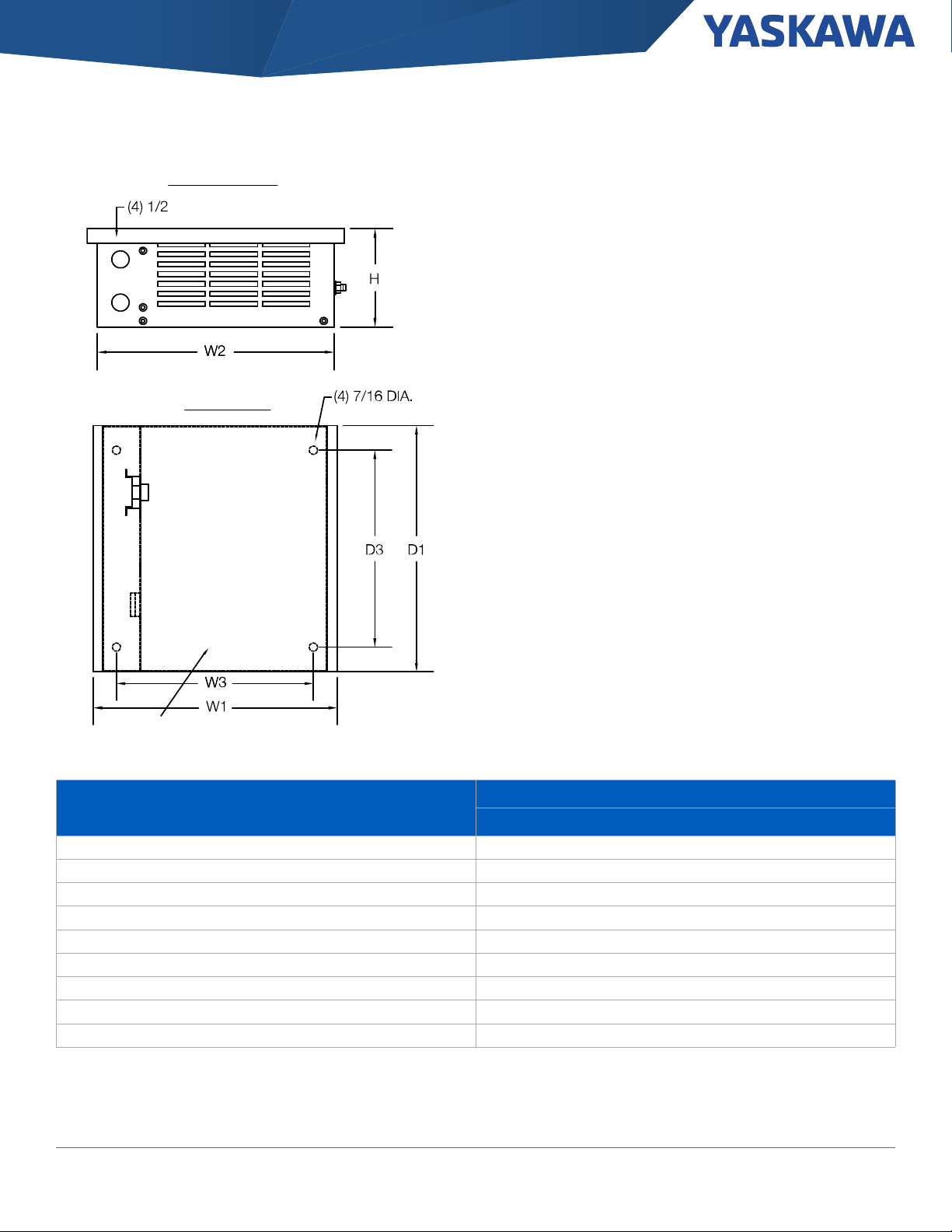
Section: Power Options \ 3% Dynamic Braking Options
Table 26: GCE Type Enclosure Dimensions (Figure. 15)
Model
W1 W2 W3 D1 D2 D3 H
GCE1 12.5 12 10.5 5.13 5 - 5
GCE2 12.5 12 10.5 7.13 7 4.5 5
GCE3 12.5 12 10.5 10.13 10 7.5 5
GCE4 12.5 12 10.5 13.13 13 10.5 5
GCE5 12.5 12 10.5 16.13 16 13.5 5
GCE6 19.5 19 17.5 10.13 10 7.5 5
GCE8 19.5 19 17.5 13.13 13 10.5 5
GCE9 27 26.5 25 10.13 10 7.5 5
GCE10 19.5 19 17.5 16.13 16 13.5 5
GCE12 27 26.5 25 13.13 13 10.5 5
GCE15 27 26.5 25 10.13 16 13.5 5
GCE18 28.5 28 26.5 10.13 10 7.5 10
GCE24 28.5 28 26.5 13.13 13 10.5 10
GCE30 28.5 28 26.5 16.13 16 13.5 10
Dimensions (in)
40 Yaskawa America, Inc., GA800 Selection Guide SL.GA800.01

Section: Power Options \ Dynamic Braking Transistor Modules
Dynamic Braking Transistor Modules
The Dynamic Brake Module is an economical solution for braking applications that do not result in large amounts of annual energy cost. Ratings
are available from 22 kW to 220 kW.
Additional Information
Brake Module Product Page Brake Module Drawings
Manual Brochure
Table 27: Brake Modules
Voltage Rating Model Number
CDBR-20220D 20 60
240 Vac
460 Vac
CDBR-20370D 24 80 5 38 150x120x157 IP20
CDBR-20550D 40 120 3.8 64 235x160x186 IP00
CDBR-21100D 80 250 1.6 152 294x175x200 IP00
CDBR-40300D 15 40
CDBR-40450D 18 60 13.4 36 150x120x157 IP20
CDBR-40900D 30 100 8 51 235x160x186 IP00
CDBR-42200D 80 250 3.2 152 294x175x200 IP00
1. Based on 10% duty, maximum 10 seconds.
Current Rating
(Amps)
Table 28: Type 1 Adapters
Voltage Rating Model Number Part Number
230 Vac
460 Vac
Current
Rating (Amps
1
Peak)
Power Supply
Vdc
240 to 400 Vdc
Peak
460 to 800 Vdc
Peak
CDBR-20220D
CDBR-20370D
CDBR-20550D EZZ022490B
CDBR-21100D EZZ022490C
CDBR-40300D
CDBR-40450D
CDBR-40900D EZZ022490B
CDBR-42200D EZZ022490C
Minimum
Connectible
Resistance
(Ohms)
6.7 27 150x120x157 IP20
20 24 150x120x157 IP20
Heat Loss (W)
Dimensions
H x W x D mm
EZZ022490A
EZZ022490A
Enclosure
Ratings
GA800 Selection Guide SL.GA800.01, Yaskawa America, Inc. 41

Table 29: Brake Unit (IP20) Dimensions
Model
CDBR-
Figure
Section: Power Options \ Dynamic Braking Transistor Modules
Figure 16: Open Type Chassis Dimensions
Dimensions (mm/in)
W H D
Weight
kg/lb
2022D
2037D
4030D
4045D
16 120 /4.72 150/5.91 157/6.18 2/4.4
Table 30: Brake Unit (IP00) Dimensions
Model
CDBR-
2055D
2110D 175/6.89 294/11.57 200/7.87 7.5/16.53
4090D 160/6.30 235/9.25 185.9/7.32 5.5/12.13
4220D 175/6.89 294/11.57 200/7.87 7.5/16.53
Figure
16
Dimensions (mm/in)
W H D
160/6.30 235/9.25 185.9/7.32 5.5/12.13
Weight
kg/lb
42 Yaskawa America, Inc., GA800 Selection Guide SL.GA800.01
Section: Power Options \ Dynamic Braking Transistor Modules
Figure 17: Type 1 Dimensions
Table 31: Brake Unit (Type 1) Dimensions
Model
CDBR-
Figure
W H D
Dimensions (mm/in)
Weight
kg/lb
2022D
2037D
2055D 165/6.50 250/9.84 185.9/7.32 5.9/13.01
2110D 180/7.09 367/14.45 200/7.87 8.3/18.30
17
4030D
4045D
4090D 165/6.50 250/9.84 185.9/7.32 5.9/13.01
4220D 180/7.09 367/14.45 200/7.87 8.3/18.30
120/4.72 190/7.48 157/6.18 2.3/5.07
120/4.72 190/7.48 157/6.18 2.3/5.07
GA800 Selection Guide SL.GA800.01, Yaskawa America, Inc. 43
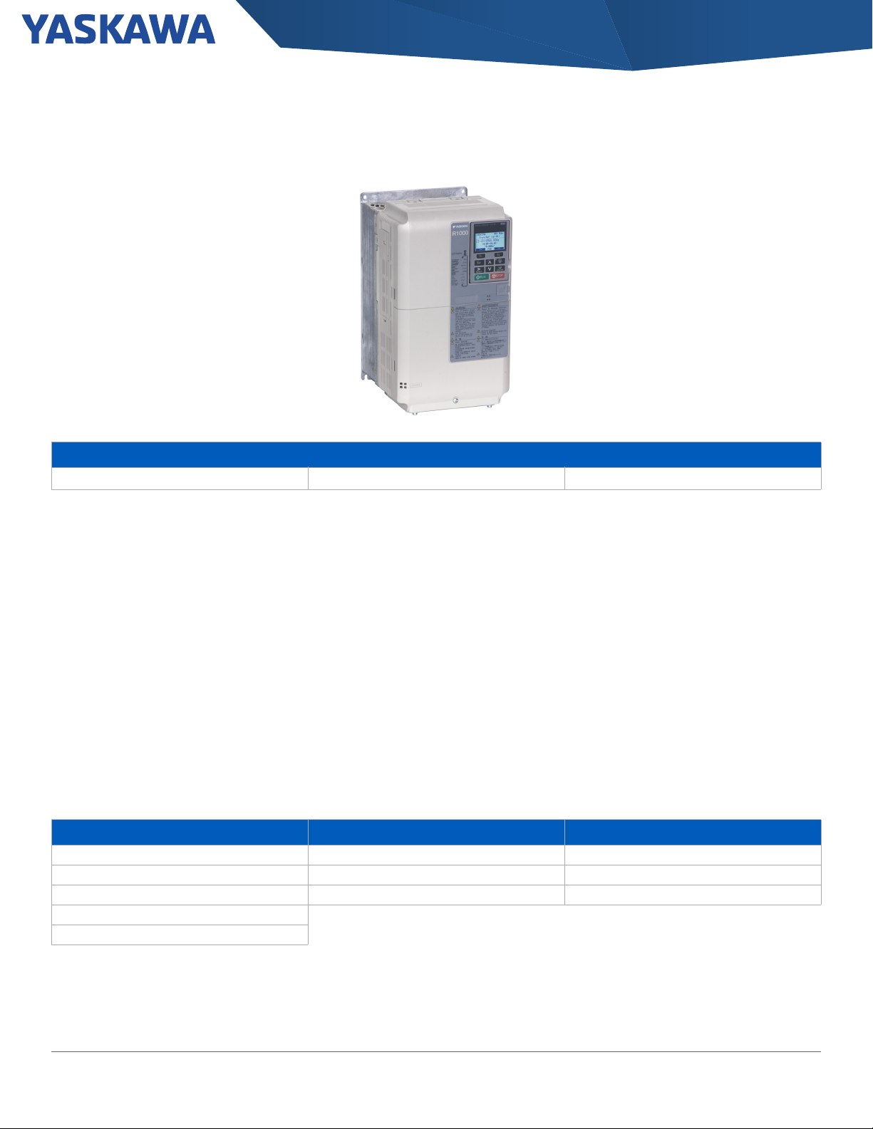
Section: Power Options \ R1000 Regenerative Systems
R1000 Regenerative Systems
Additional Information
R1000 Online Resources
• Compatible with all conventional drives having full power access
Flyer Manual
• 0.9 Power Factor at full load
to DC bus
• Overload capability of 150% for 30 seconds
• Rated for 100% power, 25% duty cycle (60 seconds maximum
on time), or 80% continuous
• Overcurrent and Overheat Protection
Each R1000 regenerative unit requires the following:
• R1000: The R1000 regenerative module is used to divert energy
generated by the motor back onto the line for use by other
loads. The energy is directed back onto the line by taking DC
voltage from the drive running the motor and converting it into a
three phase AC voltage waveform.
• Power Coordination Reactor: The power coordination
reactor provides impedance to limit peak current. The power
coordination reactor represents minimum impedance required
to limit current to levels acceptable to the R1000.
• Fuses and Fuse Holder: Recommended fusing and their
corresponding holder(s) is provided for device protection and
UL certification.
• Current Suppression Reactor: The current suppression
reactor provides impedance to protect the connected drive's
input section from peak current that may result from the R1000
IGBT switching section. The current suppression reactor
provides isolation from the dv/dt of the R1000 switching
section.
Typical Applications
Stopping Cyclic Loading Continuous Regeneration
Elevators and Lifts Presses Winders
Centrifuges Dryers Downhill Conveyors
Saws Vibratory Equipment Dynamometers
Large Fans
Machine Tool Spindles
44 Yaskawa America, Inc., GA800 Selection Guide SL.GA800.01
Section: Power Options \ R1000 Regenerative Systems
Table 32: 240 Volt R1000 Regenerative Systems
Motor
Power
HP
5 2012. . . 2018. . .
Catalog Code
GA80U . .
Normal
Duty
Heavy
Duty
R1000 Part Number
CIMR-RU__
2A03P5FAA
1 2
1
Current Suppression
Reactor
Part Number
05P00620-0134 05P00620-0136 FU-002031 FU-002055
Power Coordination
Reactor
Part Number
Fuses
( Quantity: 3)
Part Number
Fuse Holder
Part Number Quantity
2A0005FAA
1
URX000083 05P00620-0138 FU-002031 FU-002055
7.5 2021. . . 2030. . .
10 2030. . . 2042. . .
15 2042. . . 2056. . .
20 2056. . . 2070. . .
25 2070. . . 2082. . .
30 2082. . . 2100. . .
40 2110. . . 2138. . .
50 2138. . . 2169. . .
60 2169. . . 2211. . .
2A0007FAA
2A0010FAA
2A0014FAA
2A0017FAA
2A0020FAA
2A 0028FAA
2A0035AAA
2A0053AAA
1
1
1
1
1
1
2
2
URX000083 05P00620-0044 FU-002032 FU-002055
05P00620-0044 05P00620-0140 UFU000153 FU-002082
05P00620-0141 05P00620-0141 UFU000479 FU-002082
05P00620-0143 05P00620-0143 UFU000154 FU-002083
URX000085 05P00620-0143 UFU000155 FU-002083
URX000085 05P00620-0013 UFU000156 FU-002083
05P00620-0064 05P00620-0070 UFU000156 FU-002083
URX000086 05P00620-0146 UFU000494 FU-002083
75 2211. . . 2257. . .
100 2257. . . 2313. . .
125 2313. . . 2360. . .
2A0073AAA
2A0105AAA
2
2
URX000175 URX000175 UFU000375 UFU000378
URX000178 URX000181 UFU000376 UFU000122
150 2360. . . 2415. . .
1. Type 1 / IP20 enclosure is standard for CIMR-RU2A03P5FAA through CIMR-RU2A0028FAA
2. Open-Type / IP00 enclosure is standard for CIMR-RU2A0035AAA through CIMR-RU2A0105AAA
16 2018. . . 2021. . .
3
GA800 Selection Guide SL.GA800.01, Yaskawa America, Inc. 45
Section: Power Options \ R1000 Regenerative Systems
Table 33: 480 Volt R1000 Regenerative Systems
Motor
Power
HP
Catalog Code
GA80U . .
Normal
Duty
Heavy Duty
5 4009. . . 4012. . .
7.5 4012. . . 4018. . .
10 4018. . . 4023. . .
15 4023. . . 4031. . .
20 4031. . . 4038. . .
25 4038. . . 4044. . .
30 4044. . . 4060. . .
40 4060. . . 4075. . .
50 4075. . . 4089. . .
60 4089. . . 4103. . .
75 4103. . . 4140. . .
100 4140. . . 4168. . .
125 4168. . . 4208. . .
150 4208. . . 4250. . .
R1000 Part Number
CIMR-RU__
4A03P5FAA
4A0005FAA
4A0007FAA
4A0010FAA
4A0014FAA
4A0017FAA
4A0020FAA
4A0028FAA
4A0035AAA
4A0043AAA
4A0053AAA
4A0073AAA
4A0105AAA
1 2
1
1
1
1
1
1
1
1
2
2
2
2
2
Current Suppression
Reactor
Part Number
Power Coordination
Reactor
Part Number
Fuses
(Quantity: 3)
Part Number
Part
Number
05P00620-0025 05P00620-0133 FU-002030 FU-002055
05P00620-0133 05P00620-0135 FU-002030 FU-002055
05P00620-0135 05P00620-0137 FU-002030 FU-002055
05P00620-0137 05P00620-0138 FU-002032 FU-002055
URX000083 05P00620-0139 FU-002032 FU-002082
05P00620-0044 05P00620-0139 FU-000783 FU-002082
05P00620-0049 05P00620-0049 FU-000783 FU-002082
05P00620-0142 05P00620-0142 UFU000480 FU-002082
05P00620-0144 05P00620-0144 FU-000806 FU-002084
05P00620-0143 05P00620-0144 FU-000807 FU-002084
URX000085 05P00620-0145 FU-000809 FU-002084
05P00620-0064 05P00620-0070 FU-000809 FU-002084
05P00620-0075 05P00620-0146 UFU000374 UFU000378
Fuse Holder
Quantity
1
3
200 4250. . . 4302. . .
4A0150AAA
2
URX000175 URX000176 UFU000375 UFU000378
250 4302. . . 4371. . .
300 4371. . . 4414. . .
4A0210AAA
2
URX000181 URX000182 UFU000376 UFU000122
350 4414. . . 4477. . .
400 4477. . . 4568. . .
4A0300AAA
2
URX000088 05P00620-0094 UFU000377 UFU000122450 4568. . . 4605. . .
500 4605. . . 4720. . .
1. Type 1/ IP20 enclosure is standard for CIMR-RU4A03P5FAA through CIMR-RU4A0028FAA
2. Open-Type / IP00 enclosure is standard for CIMR-RU4A0035AAA through CIMR-RU4A0300AAA
3
46 Yaskawa America, Inc., GA800 Selection Guide SL.GA800.01

Section: Power Options \ R1000 Regenerative Systems
Table 34: R1000 Reactor Dimensions (Open Type)
Dimensions
Reactor
Part Number
05P00620-0013 130 0.20 180 229/9 183/7.2 172/6.8 93/3.66 92/3.63 28/62
05P00620-0025 8 5.0 25.3 152/6.0 122/4.8 86/3.4 67/2.62 51/2.00 5.0/11
05P00620-0044 35 0.4 49 183/7.2 147/5.8 102/4.0 66/2.60 76/3.00 6.4/14
05P00620-0049 45 0.7 62 229/9.0 188/7.4 119/4.7 80/3.16 76/3.00 13/28
05P00620-0064 130 0.10 108 229/9.0 179/7.1 118/4.7 80/3.16 76/3.00 13/29
05P00620-0070 160 0.150 149 274/10.8 277/8.3 152/6 88/3.47 92/3.63 23/51
05P00620-0075 200 0.055 124 229/9 191/7.5 185/7.3 106/4.16 92/3.63 22/49
05P00620-0094 500 0.050 340 366/14.4 292/11.5 292/11.5 172/6.76 117/4.60 82/180
05P00620-0133 8 3.0 29 152/6.0 122/4.8 76/3.0 53/2.10 51/2.00 3.6/8
05P00620-0134 12 1.25 26 152/6.0 127/5.0 84/3.3 53/2.10 51/2.00 4.1/9
05P00620-0135 12 2.5 31 152/6.0 127/5.0 84/3.3 53/2.10 51/2.00 4.5/10
05P00620-0136 18 0.8 36 152/6.0 135/5.3 81/3.2 54/2.10 51/2.00 4.1/9
05P00620-0137 18 1.5 43 152/6.0 135/5.3 89/3.5 63/2.48 51/2.00 5.5/12
05P00620-0138 25 1.2 52 183/7.2 147/5.8 89/3.5 60/2.35 76/3.00 6.4/14
05P00620-0139 35 0.8 54 183/7.2 147/5.8 102/4.0 70/2.75 76/3.00 7.3/16
05P00620-0140 45 0.3 54 229/9.0 188/7.4 119/4.7 80/3.16 76/3.00 10/23
05P00620-0141 55 0.25 64 229/9.0 185/7.3 135/5.3 80/3.16 76/3.00 11/24
05P00620-0142 55 0.50 67 229/9.0 178/7.0 135/5.3 80/3.16 76/3.00 12/27
05P00620-0143 80 0.20 82 229/9 183/7.2 160/6.3 88/3.47 92/3.63 20/43
05P00620-0144 80 0.40 86 229/9 183/7.2 165/6.5 88/3.47 92/3.63 23/51
05P00620-0145 100 0.30 84 229/9 185/7.3 173/6.8 93/3.66 92/3.63 23/51
05P00620-0146 200 0.110 168 229/9 191/7.5 211/8.3 112/4.41 92/3.63 31/67
URX000083 25 0.5 48 183/7.2 147/5.8 89/3.5 60/2.35 76/3.00 5.0/11
URX000085 100 0.15 94 229/9 185/7.3 165/6.5 88/3.46 92/3.62 21/47
URX000086 160 0.230 138 292/11.5 216/8.5 229/9.0 118/4.66 92/3.63 33/72
URX000088 500 0.025 266 274/10.8 229/9 267/10.5 140/5.50 117/4.60 55/120
URX000175 250 0.045 154 229/9 191/7.5 229/9 106/4.16 92/3.63 31/68
URX000176 250 0.090 231 274/10.8 216/8.5 229/9 131/5.16 117/4.60 48/106
URX000178 320 0.040 224 274/10.8 229/9 277/8.3 131/5.16 117/4.60 50/110
URX000181 400 0.030 231 274/10.8 254/10 254/10.0 131/5.16 117/4.60 46/100
URX000182 400 0.060 333 381/15 286/11.3 292/11.5 172/6.76 117/4.60 71/155
Current
Rating (A)
Inductance
(mH)
Watt Loss
A B C D E
mm/in mm/in mm/in mm/in mm/in
Weight
kg/lb
GA800 Selection Guide SL.GA800.01, Yaskawa America, Inc. 47

Section: Power Options \ R1000 External Heatsink Kits
R1000 External Heatsink Kits
External Heatsink Kit: Allows drives to be mounted with the drive’s heatsink external (Type 1 backside) to the enclosure. Option kit for customer
mounting. Larger standard drives include brackets.
Table 35: R1000 External Heatsink Kit for Type 1 240 Volt Models
Rated Input Voltage Drive Model Number CIMR-RU2A . . Part Number
03P5
EZZ020800B0005
0007
200 to 240 Volt Three-Phase
0010
0014
0017
0028
0035
0053
0073
0105
EZZ020800C
EZZ020800D0020
Required brackets are
included with the drive.
Table 36: R1000 External Heatsink Kits for Type 1 for 480 Volt Models
Rated Input Voltage Drive Model Number CIMR-RU4A . . Part Number
03P5
0007
0010
0014
0017
400 to 480 Volt Three-Phase
0028
0035
0053
0073
0105
0150
0210
0300
EZZ020800B0005
EZZ020800C
EZZ020800D0020
Required brackets are
included with the drive.
48 Yaskawa America, Inc., GA800 Selection Guide SL.GA800.01

Section: Power Options \ Single Phase Converter
Single Phase Converter
Yaskawa’s industry leading Single Phase Converter (SPC) cleanly converts single-phase AC power to DC power for Yaskawa variable
frequency drives. The SPC combines Yaskawa reliability and drive technology with motor control solutions for businesses in remote areas. The
SPC eliminates the need to oversize variable frequency drives for single-phase applications while reducing distortion to less than 10% iTHD.
With lower input harmonics and near unity power factor, the SPC also eliminates the need to significantly oversize transformers in single-phase
applications, reducing overall installation costs. The Single Phase Converter addresses these common issues with AC motors powered from
single-phase input:
• Limited single-phase motor options.
• Increased maintenance of rotating parts and tuned circuits.
• Inefficient use of power due to choppy current harmonics.
Item Specification
Power Range
Input Voltage Tolerance
Power Factor 0.99
Ambient Operating Temperature -10 to 50 °C (14 to 122 °F) Open Chassis
Global Certifications UL, RoHS
User Interface 4 LED indicators: Power, Ready, Run, Fault
1. -10 % Minimum input voltage for 60 seconds at rated power.
Additional Information
Single Phase Converter Manual
Specifications Drawings
230 Vac: 20 - 60 HP
460 Vac: 30 - 125 HP
230-240 Vac, Single-Phase
460-480 Vac, Single-Phase
To l e r an c e -5 / + 10 %
1
GA800 Selection Guide SL.GA800.01, Yaskawa America, Inc. 49

Section: Power Options \ Single Phase Converter
Table 37: Single Phase Converters - 20 to 60 HP
Power Supply
System Kit
Number
SPBC-240-20HP 20 79 57 15 (381 10 (254) 10 (254)
SPBC-240-30HP 30 116 84 15 (381) 10 (254) 10 (254)
1
Rated Power HP
2
Input Current
(Amps)
Output Current
(Amps)
Height
inches (mm)
Width
inches (mm)
Depth
inches (mm)
230 - 240 Vac
460 - 480 Vac
SPBC-240-40HP 40 154 112 17 (432) 12 (305) 10.5 (267)
SPBC-240-50HP 50 191 109 25 (636) 12.2 (310) 11.4 (290)
SPBC-240-60HP 60 228 166 25 (636) 12.2 (310) 11.4 (290)
SPBC-480-30HP 30 58 42 15 (381) 10 (254) 10 (254)
SPBC-480-40HP 40 77 56 15 (381) 10 (254) 10 (254)
SPBC-480-50HP 50 96 69 17 (432) 12 (305) 10.5 (267)
SPBC-480-60HP 60 114 83 17 (432) 12 (305) 10.5 (267)
SPBC-480-75HP 75 142 103 25 (636) 12.2 (310) 11.4 (290)
SPBC-480-125HP 125 (93) 234 170 25 (636) 12.2 (310) 14.7 (375)
1. The kit includes open type/protected chassis Single Phase Converter and DC link choke.
2. The larger power Single Phase Converter unit may be used on lower power motors.
50 Yaskawa America, Inc., GA800 Selection Guide SL.GA800.01

Section: Drive Derating \ Single-Phase Derating
Drive Derating
Single-Phase Derating
The GA800 is optimized for use on three-phase power, but may be derated for use in single-phase to three-phase conversion applications.
Use the table below to select the appropriate drive model based on the AC line and motor voltage.
Table 38: 240 Volt Single-Phase Drive Derating
No
Reactor
With
Reactor
AC Input Type DC Bus Type
Drive Catalog Code
GA80U . .
1 2
2004 . . . 1/3 1/2 URX000303 URX000411 URX000043
2006 . . . 1/2 3/4 URX000303 URX000411 URX000043
2008 . . . 3/4 1 URX000307 URX000413 05P00620-0113 URX000435
2010 . . . 1 1.5 URX000316 URX000419 05P00620-0115 URX000259
2012 . . . 1.5 2 URX000315 URX000418 05P00620-0115 URX000259
2018 . . . 2 3 URX000319 URX000420 URX000050 Not available
2021 . . . 2 3 URX000323 URX000422 05P00620-0120 URX000261
2030 . . . 2 5 URX000323 URX000422 05P00620-0120 URX000261
2042 . . . 3 7.5 URX000326 URX000424 05P00620-0123 URX000436
2056 . . . 3 7.5 URX000326 URX000424 URX000059 URX000262
2070 . . . 5 10 URX000332 URX000426 URX000063 URX000264
2082 . . . 7.5 10 URX000338 URX000428 URX000072 URX000266
2110 . . . 10 15 URX000338 URX000428
2138 . . . 10 10 URX000338 URX000428
2169 . . . 15 20 URX000344 URX000430
2211 . . . 20 25 URX000347 URX000431
2257 . . . 30 30 Do not use reactor for this rating
2313 . . . 30 40 URX000353 URX000433
2360 . . . 40 50 URX000353 URX000433
2415 . . . 50 60 URX000356 URX000434
Drive
Output
Capacity
HP HP
Drive
Output
Capacity
Open Type 1 Enclosed Open Type 1 Enclosed
Part
Number
Part
Number
Part
Number
Drives 2110 and larger
include integrated DC bus reactor
Part
Number
Not Available
1. This information reflects derating of three-phase drives for single-phase input applications. Refer to the Single Phase Converter to select a converter that
provides full power (no derating) for some drives when used with single-phase power.
2. Select the partial catalog code from this single-phase table, then refer to the Three-Phase Drive table to select the complete drive catalog code based on
enclosure type.
GA800 Selection Guide SL.GA800.01, Yaskawa America, Inc. 51
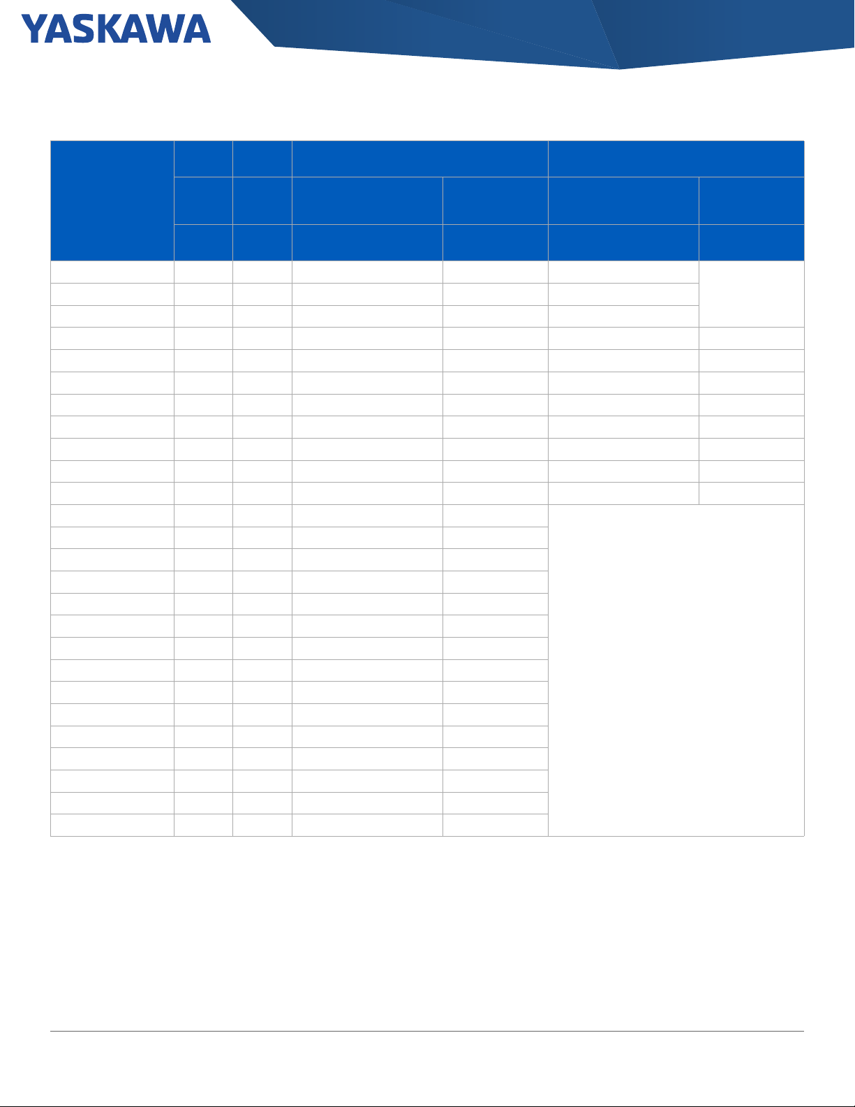
Section: Drive Derating \ Single-Phase Derating
Table 39: 480 Volt Single-Phase Drive Derating
No
Reactor
With
Reactor
AC Input Type DC Bus Type
Drive Catalog Code
GA80U . .
1 2
4002 . . . 1/3 1/2 URX000295 URX000409 05P00608-3007
4005 . . . 1 1.5 URX000303 URX000411 05P00608-3007
4007 . . . 1 2 URX000308 URX000414 05P00652-0213 URX000209
4009 . . . 2 3 URX000312 URX000416 05P00652-0113 URX000435
4012 . . . 2 3 URX000316 URX000419 05P00620-0115 URX000259
4018 . . . 3 5 URX000316 URX000419 URX000052 URX000211
4023 . . . 3 5 URX000316 URX000419 URX000052 URX000211
4031 . . . 3 10 URX000324 URX000423 URX000055 URX000223
4038 . . . 5 10 URX000326 URX000424 05P00620-0123 URX000436
4044 . . . 5 15 URX000330 URX000553 URX000059 URX000262
4060 . . . 10 10 URX000332 URX000426
4075 . . . 10 15 URX000333 URX000554
4089 . . . 15 15 URX000335 URX000427
4103 . . . 15 15 URX000338 URX000428
4140 . . . 25 25 URX000341 URX000429
4168 . . . 25 30 URX000341 URX000429
4208 . . . 50 50 URX000347 URX000431
4250 . . . 50 50 URX000350 URX000432
4302 . . . 50 60 URX000353 URX000433
4371 . . . 75 75 URX000356 URX000434
4414 . . . 100 100 URX000356 URX000434
4477 . . . 125 150 URX000359 URX000566
4568 . . . 125 150 URX000359 URX000566
4605 . . . 150 200 URX000365 URX000581
4720 . . . 150 200 URX000365 URX000581
Drive
Output
Capacity
HP HP
Drive
Output
Capacity
Open Type 1 Enclosed Open Type 1 Enclosed
Part
Number
Part
Number
Part
Number
Drives 4060 and larger
include integrated DC bus reactor
Number
Not Available4004 . . . 3/4 1 URX000303 URX000411 05P00608-3007
Part
1. This information reflects derating of three-phase drives for single-phase input applications. Refer to the Single Phase Converter to select a converter that
provides full power (no derating) for some drives when used with single-phase power.
2. Select the partial catalog code from this single-phase table, then refer to the Three-Phase Drive table to select the complete drive catalog code based on
enclosure type.
52 Yaskawa America, Inc., GA800 Selection Guide SL.GA800.01

Section: Drive Derating \ Carrier Frequency Derating
Carrier Frequency Derating
Table 40: 240 Volt Carrier Frequency Derating
Carrier Frequency Derating (240 V Class) 1
Catalog Code
GA80U . .
2 kHz 5 kHz 8 kHz 10 kHz 12.5 kHz 15 kHz 2 kHz 5 kHz 8 kHz 10 kHz 12.5 kHz 15 kHz
2004. . . 3.2 3.2 3.2 3.1 2.9 2.78 3.5 3.3 2.9 2.7 2.4 2.1
2006. . . 5 5 5 4.8 4.6 4.3 6 5.6 5 4.6 4.1 3.6
2010. . . 8 8 8 7.4 6.6 5.8 9.6 9 8 7.4 6.6 5.8
2012. . . 11 11 11 10.4 9.6 8.8 12 11.7 11 10.5 9.9 9.3
2018. . . 14 14 14 12.6 10.8 9.1 17.5 16.1 14 12.6 10.8 9.1
2021. . . 17.5 17.5 17.5 16.1 14.3 12.6 21 19.6 17 16.1 14.3 12.5
2030. . . 25 25 25 23 20.5 18 30 28 25 23 20.5 18
2042. . . 33 33 33 29.3 24.8 20.2 42 38.4 33 29.4 24.9 20.4
2056. . . 47 47 47 43.4 38.9 34.4 56 52.4 47 43.4 38.9 34.4
2070. . . 60 60 60 56 51 46 70 66 60 56 51 46
2082. . . 75 75 75 68.6 60.5 53 82 82 75 68.8 61 53.1
2110. . . 88 88 88 80.5 71 62 110 102.7 92 84.3 75.2 66
2138. . . 115 115 115 105.1 92.8 81 138 128.8 115 105.8 94.3 82.8
2169. . . 145 145 125.2 112 - - 169 152.7 128.3 112 - -
2211. . . 180 180 155.2 138.6 - - 211 190.2 158.9 138.1 - -
2257. . . 215 215 184.8 164.7 - - 257 230.4 190.5 163.9 - -
2313. . . 283 283 249 226.4 - - 313 288.5 251.7 227.1 - -
2360. . . 346 346 294.3 259.8 - - 360 330.8 287.6 258.8 - -
2415. . . 415 415 365.2 332 - - ------
Heavy Duty Rating Amps Normal Duty Rating Amps
2
1. Applicable Motor Control Methods: GA800 Parameter A1-02 = 0, 1, 2, 3, 4, 5, 7, 8.
2. Refer to the GA800 Technical Manual for AOLV/PM Carrier Frequency Derating information.
GA800 Selection Guide SL.GA800.01, Yaskawa America, Inc. 53

Section: Drive Derating \ Carrier Frequency Derating
Table 41: 480 Volt Carrier Frequency Derating
Carrier Frequency and Rated Current Derating (480 V Class) 1
Catalog Code
GA80U . .
2 kHz 5 kHz 8 kHz 10 kHz 12.5 kHz 15 kHz 2 kHz 5 kHz 8 kHz 10 kHz 12.5 kHz 15 kHz
4002. . . 1.8 1.8 1.8 1.6 1.3 1 2.1 2 1.8 1.7 1.5 1.4
4004. . . 3.4 3.4 3.4 2.9 2.3 1.7 4.1 3.8 3.4 3.1 2.8 2.4
4005. . . 4.8 4.8 4.8 4.3 3.7 3 5.4 5.2 4.8 4.6 4.3 3.9
4007. . . 5.5 5.5 5.5 4.9 4.1 3.2 7.1 6.5 5.5 4.8 4 3.2
4009. . . 7.2 7.2 7.2 6.5 5.6 4.8 8.9 8.2 7.2 6.5 5.6 4.8
4012. . . 9.2 9.2 9.2 8.1 6.8 5.4 11.9 10.8 9.2 8.1 6.7 5.4
4018. . . 14.8 14.8 14.8 13.1 11 8.9 17.5 17.3 14.8 13.1 11 8.9
4023. . . 18 18 18 15.9 13.4 10.8 23 21.5 18.3 16.2 13.6 11
4031. . . 24 24 24 21.2 17.7 14.1 31 28.2 24 21.1 17.6 14.1
4038. . . 31 31 31 27.5 23 18.6 38 36.3 31 27.5 23 18.6
4044. . . 39 39 39 34.5 29 23.4 44 43.6 37.5 33.5 28.4 23.4
4060. . . 45 45 45 39.1 31.8 24.4 60 53.7 44.9 39.1 31.7 24
4075. . . 60 60 60 53.1 44.6 36 75 73.8 62.9 55.6 46.5 37
4089. . . 75 75 75 66.4 55.7 45 89 88.8 75.8 67.2 56.4 46
4103. . . 91 91 91 80.6 67.6 54.6 103 103 90.3 80.1 67.3 55
4140. . . 112 112 91.8 78.4 - - 140 122.8 96.7 79 - -
4168. . . 150 150 123 105 - - 168 150.5 124.4 107 - -
4208. . . 180 180 147.6 126 - - 208 179.7 137.2 109 - -
4250. . . 216 216 177.1 151.2 - - 250 221.8 179.4 151 - -
4302. . . 260 260 213.2 182 - - 296 263.4 214.6 182 - -
4371. . . 304 304 249.3 212.8 - - 371 327.2 261.6 218 - -
4414. . . 371 371 304.2 259.7 - - 389 348 286.3 245 - -
4477. . . 389 324.8 - - - - 453 349 - - - -
4568. . . 453 378.3 - - - - 568 437 - - - -
4605. . . 605 505.2 - - - - 675 529 - - - -
Heavy Duty Rating Amps Normal Duty Rating Amps
2
1. Applicable Motor Control Methods: GA800 Parameter A1-02 = 0, 1, 2, 3, 4, 5, 7, 8.
2. Refer to the GA800 Technical Manual for AOLV/PM Carrier Frequency Derating information.
54 Yaskawa America, Inc., GA800 Selection Guide SL.GA800.01

Section: Drive Derating \ Altitude
Altitude
Install the drive in a location that with an altitude of 1000 m (3281 ft) or lower. Derate the output current by 1% for each 100 m (328 ft) to install
the drive in altitudes between 1000 m to 3000 m (3281 ft to 9843 ft). It is not necessary to derate the rated voltage in these conditions:
• Installing the drive at 2000 m (6562 ft) or lower. • Installing the drive between 2000 m to 3000 m (6562 ft to 9843
ft) and grounding the neutral point on the power supply.
Contact Yaskawa or your nearest sales representative when the drive is not grounded with the neutral network.
Ambient Temperature
Open chassis type (IP20): -10 °C to +50 °C (14 °F to 122 °F)
Enclosed wall-mounted type (Type 1): -10 °C to +40 °C (14 °F to 104 °F)
• Drive reliability is better in environments that do not have wide
temperature fluctuations.
• When installing the drive in an enclosure, use a cooling fan or air
conditioner to keep the internal air temperature in the permitted
range.
Figure 18: Ambient Temperature Derating Chart
• Do not let the drive freeze.
• To install the drive in areas with ambient temperatures 40 °C to
60 °C (104 °F to 140 °F), derate the output current and output
voltage.
GA800 Selection Guide SL.GA800.01, Yaskawa America, Inc. 55

Section: Watt Loss \
Watt Loss
Table 42: 240 Volt Model Watt Loss
240 V Normal Duty 240 V Heavy Duty
Catalog
Code
GA80U . .
2004. . . 4.2 2 35 18 53 3.5 8 35 19 54
2006. . . 6 2 38 25 63 5 8 37 26 63
2008. . . 8 2 42 34 76 6.9 8 40 36 76
2010. . . 9.6 2 49 46 95 8 8 44 43 87
2012. . . 12.2 2 56 62 118 11 8 50 61 111
2018. . . 17.5 2 53 88 141 14 8 47 82 129
2021. . . 21 2 75 125 200 17.5 8 56 105 161
2030. . . 30 2 95 206 301 25 8 74 174 248
2042. . . 42 2 129 227 356 33 8 88 183 271
2056. . . 56 2 149 302 451 47 8 112 267 379
2070. . . 70 2 177 403 580 60 8 145 373 518
2082. . . 82 2 202 467 669 75 8 179 478 657
2110. . . 110 2 192 631 823 88 8 155 563 718
2138. . . 138 2 269 814 1083 115 8 212 680 892
2169. . . 169 2 338 941 1279 145 5 275 820 1095
2211. . . 211 2 384 1131 1515 180 5 314 991 1305
2257. . . 257 2 519 1534 2053 215 5 398 1252 1650
2313. . . 313 2 579 1794 2373 283 5 502 1643 2145
2360. . . 360 2 655 2071 2726 346 5 582 1978 2560
2415. . . 415 2 608 2156 2764 415 5 644 2359 3003
Note: Refer to the GA800 Drive Technical Manual (SIEPC71061737) for detailed Carrier Frequency Watt Loss information.
Rated
Output
Current
A
Carrier
Frequency
kHz
Interior Unit
Loss
W
Cooling Fin
Loss
W
Total Loss
W
Rated
Output
Current
A
Carrier
Frequency
kHz
Interior Unit
Loss
W
Cooling Fin
Loss
W
Total Loss
W
56 Yaskawa America, Inc., GA800 Selection Guide SL.GA800.01

Section: Watt Loss \
Table 43: 480 Volt Model Watt Loss
480 V Normal Duty 480 V Heavy Duty
Catalog
Code
GA80U . .
4002. . . 2.1 2 39 16 55 1.8 8 38 15 53
4004. . . 4.1 2 44 33 77 3.4 8 42 28 70
4005. . . 5.4 2 48 31 79 4.8 8 46 37 83
4007. . . 7.1 2 52 44 96 5.5 8 48 45 93
4009. . . 8.9 2 42 58 100 7.2 8 37 63 98
4012. . . 11.9 2 57 84 141 9.2 8 46 82 128
4018. . . 17.5 2 82 144 226 14.8 8 65 140 205
4023. . . 23.4 2 108 185 293 18 8 73 150 223
4031. . . 31 2 138 222 360 24 8 101 211 312
4038. . . 38 2 145 270 415 31 8 119 272 391
4044. . . 44 2 168 335 503 39 8 148 354 502
4060. . . 59.6 2 157 444 601 45 8 126 389 515
4075. . . 74.9 2 185 527 712 60 8 165 527 692
4089. . . 89.2 2 212 665 877 75 8 184 617 801
4103. . . 103 2 264 766 1030 91 8 237 779 1016
4140. . . 140 2 393 1126 1519 112 5 300 956 1256
4168. . . 168 2 574 1348 1922 150 5 486 1274 1760
4208. . . 208 2 493 1465 1958 180 5 446 1432 1878
4250. . . 250 2 686 1738 2424 216 5 558 1464 2022
4302. . . 302 2 817 2257 3074 260 5 692 2061 2753
4371. . . 371 2 1022 2553 3575 304 5 824 2346 3170
4414. . . 414 2 873 2422 3295 371 5 777 2212 2989
4477. . . 477 2 1183 3329 4512 414 2 963 2696 3659
4568. . . 568 2 1429 3989 5418 477 2 1183 3329 4512
4605. . . 675 2 1526 4572 6098 605 2 1328 3995 5323
4720. . . 720 2 1723 5184 6907 605 2 1395 4198 5593
Note: Refer to the GA800 Drive Technical Manual (SIEPC71061737) for detailed Carrier Frequency Watt Loss information.
Rated
Output
Current
A
Carrier
Frequency
kHz
Interior Unit
Loss
W
Cooling Fin
Loss
W
Total Loss
W
Rated
Output
Current
A
Carrier
Frequency
kHz
Interior Unit
Loss
W
Cooling Fin
Loss
W
Total Loss
W
GA800 Selection Guide SL.GA800.01, Yaskawa America, Inc. 57

Section: Drive Short Circuit Protection \
Drive Short Circuit Protection
Table 44: 240 Volt Model Protection Ratings
Semiconductor Fuses
EATON/Bussmann
Drive
Catalog
Code
GA80U . .
2004. . . FWH-45B 100 kA 7 100 kA 15 7 4,195 100 kA
2006. . . FWH-45B 100 kA 10 100 kA 15 10 4,195 100 kA
2008. . . FWH-45B 100 kA 12 100 kA 15 12 4,195 100 kA
2010. . . FWH-45B 100 kA 15 100 kA 15 15 4,195 100 kA
2012. . .
2018. . .
2021. . .
2030. . .
2042. . . FWH-150B 100 kA 70 100 kA 80 70 4,195 100 kA
Part
Number
FWH-50B
or FWH-80B
FWH-80B
or FWH-100B
FWH-80B
or FWH-100B
FWH-100B
or FWH-125B
1
Maximum
SCCR
(Fuse-Drive
Combination)
100 kA 20 100 kA 20 20 4,195 100 kA
100 kA 30 100 kA 35 30 4,195 100 kA
100 kA 35 100 kA 40 35 4,195 100 kA
100 kA 50 100 kA 60 50 4,195 100 kA
Class CC, J, or T Fuses
Maximum Fuse
Size (Amps)
Maximum SCCR
2
(Fuse-Drive
Combination)
Maximum
MCCB Size
(Amps)
MCCBs (Molded Case Circuit Breakers)
or Class RK Fuses
Maximum
RK1 or RK5
Fuse Size
(Amps)
3
Minimum
Enclosure
Volume
(cu in.)
Maximum
SCCR
(MCCB-Drive
or
RK Fuse-Drive
Combination)
2056. . . FWH-200B 100 kA 90 100 kA 110 90 4,195 100 kA
2070. . .
2082. . .
2110. . .
2138. . .
2169. . .
2211. . .
2257. . . FWH-600A 100 kA 400 100 kA 500 400 14,657 100 kA
2313. . .
2360. . .
2415. . . FWH-1000A 100 kA 700 100 kA 800
FWH-200B
or FWH-225A
FWH-225A
or FWH-250A
FWH-225A
or FWH-250A
FWH-275A
or FWH-300A
FWH-275A
or FWH-350A
FWH-325A
or FWH-450A
FWH-700A
or FWH-800A
FWH-800A
or FWH-1000A
100 kA 110 100 kA 125 110 4,195 100 kA
100 kA 125 100 kA 150 125 4,195 100 kA
100 kA 175 100 kA 200 175 10,121 100 kA
100 kA 225 100 kA 250 225 10,121 100 kA
100 kA 250 100 kA 300 250 10,121 100 kA
100 kA 350 100 kA 400 350 10,121 100 kA
100 kA 500 100 kA 600 500 14,657 100 kA
100 kA 600 100 kA 700 600 52,800 100 kA
Not
Applicable
52,800 100 kA
1. When semiconductor fuses are used for UL listed drive protection, the drives and fusing must be in the same enclosure. Where multiple semiconductor fuse
ratings are listed for a single drive, Yaskawa recommends the larger fuse for cyclical load applications that frequently approach 150% overload. Smaller
semiconductor fuses (than what is listed) of the same manufacturer and series are permitted; however, this may cause fuses to clear prematurely.
2. When class CC, J, or T fuses are used for UL listed drive protection, there are no enclosure requirements for 240 V models.
3. When using MCCBs, RK1 fuses, or RK5 fuses as UL listed drive protection, the drives must be mounted in ventilated enclosures according to the minimum
enclosure volume specified. When using MCCBs, Yaskawa recommends current limiting type.
58 Yaskawa America, Inc., GA800 Selection Guide SL.GA800.01

Section: Drive Short Circuit Protection \
Table 45: 480 Volt Model Protection Ratings
Semiconductor Fuses
EATON/Bussmann
Drive
Catalog
Code
GA80U . .
4002. . .
4004. . . FWH-50B 100 kA 7 100 kA 15 7 4,195 100 kA
4005. . . FWH-50B 100 kA 9 100 kA 15 9 4,195 100 kA
4007. . . FWH-60B 100 kA 12 100 kA 15 12 4,195 100 kA
4009. . . FWH-60B 100 kA 15 100 kA 15 15 4,195 100 kA
4012. . . FWH-60B 100 kA 20 100 kA 20 20 4,195 100 kA
4018. . . FWH-80B 100 kA 30 100 kA 35 30 4,195 100 kA
4023. . . FWH-90B 100 kA 40 100 kA 45 40 4,195 100 kA
4031. . .
4038. . . FWH-200B 100 kA 60 100 kA 75 60 4,195 100 kA
4044. . . FWH-200B 100 kA 70 100 kA 80 70 4,195 100 kA
4060. . . FWH-225A 100 kA 100 100 kA 110 100 4,195 100 kA
4075. . . FWH-250A 100 kA 125 100 kA 150 125 10,121 100 kA
4089. . .
4103. . .
4140. . . FWH-300A 100 kA 225 100 kA 250 225 10,121 100 kA
4168. . .
4208. . . FWH-500A 100 kA 350 100 kA 400 350 14,657 100 kA
4250. . . FWH-600A 100 kA 400 100 kA 500 400 14,657 100 kA
4302. . . FWH-700A 100 kA 500 100 kA 600 500 14,657 100 kA
4371. . . FWH-800A 100 kA 600 100 kA 700 600 52,800 100 kA
4414. . .
4477. . .
4568. . .
4605. . .
4720. . .
Part
Number
FWH-40B
or FWH-50B
FWH-125B
or FWH-150B
FWH-250A
or FWH-275A
FWH-250A
or FWH-275A
FWH-325A
or FWH-400A
FWH-800A
or FWH-1000A
FWH-1000A
or FWH-1200A
FWH-1000A
or FWH-1200A
FWH-1200A
or FWH-1400A
FWH-1200A
or FWH-1400A
1
Maximum
SCCR
(Fuse-Drive
Combination)
100 kA 3.5 100 kA 15 3.5 4,195 100 kA
100 kA 50 100 kA 60 50 4,195 100 kA
100 kA 150 100 kA 175 150 10,121 100 kA
100 kA 175 100 kA 200 175 10,121 100 kA
100 kA 250 100 kA 300 250 10,121 100 kA
100 kA 700 100 kA 800
100 kA 800 100 kA 900 52,800 100 kA
100 kA 900 100 kA 1000 52,800 100 kA
100 kA 1000 100 kA 1200 52,800 100 kA
100 kA 1200 100 kA 1400 52,800 100 kA
Class CC, J, or T Fuses
Maximum Fuse
Size (Amps)
Maximum SCCR
2
(Fuse-Drive
Combination)
Maximum
MCCB Size
(Amps)
MCCBs (Molded Case Circuit Breakers)
or Class RK Fuses
Maximum
RK1 or RK5
Fuse Size
(Amps)
Not
Applicable
3
Minimum
Enclosure
Volume
(in3)
52,800 100 kA
Maximum
SCCR
(MCCB-Drive
or
RK Fuse-Drive
Combination)
1. When semiconductor fuses are used for UL listed drive protection, the drives and fusing must be in the same enclosure. Where multiple semiconductor fuse
ratings are listed for a single drive, Yaskawa recommends the larger fuse for cyclical load applications that frequently approach 150% overload. Smaller
semiconductor fuses (than what is listed) of the same manufacturer and series are permitted; however, this may cause fuses to clear prematurely.
2. When using class CC, J, or T fuses as UL listed drive protection, models 4371 and larger have the same enclosure requirements as MCCBs.
3. When using MCCBs, RK1 fuses, or RK5 fuses as UL listed drive protection, the drives must be mounted in ventilated enclosures according to the minimum
enclosure volume specified. When using MCCBs, Yaskawa recommends current limiting type.
GA800 Selection Guide SL.GA800.01, Yaskawa America, Inc. 59

Section: GA800 Configured Package Specifications
GA800 Configured Package Specifications
1 - 600 HP Type 1, Type 12, & Type 3R GA800 Configured
Packages
The GA800 Configured package provides a GA800 Drive in a Type 1, Type 12, or Type 3R industrial enclosure, with space for several commonly
used options, such as reactors, RFI filters, circuit breakers, etc. The GA800 configured has been designed for flexibility in providing commonly
requested features and options.
Wall Mount Single-Door Floor Mount Two-Door Floor Mount
Ratings, Standards, Conditions, & Options
Ratings Standards and Reliability
1 to 150 HP @ 240 Vac
1 to 600 HP @ 480 Vac
For drive performance features, see SL.GA800.01
UL 508A (Industrial Control Panels)
UL, cUL Listed
60 Yaskawa America, Inc., GA800 Selection Guide SL.GA800.01

Section: GA800 Configured Package Specifications
Service Conditions Configured Options
Ambient Temperature: -10 to 40 °C (14 to 104 °F)
Ambient Storage Temperature: -20 to 60 °C (-4 to 140 °F)
Humidity: 0% to 95%, non-condensing
Altitude: to 1000 meters (3300 feet); higher by derating
Feedback Cards
Input and Output Cards
Network Communications
Input Breaker
Input Disconnect
Input Fuses
120 Vac Interfaces
Line/Load Reactors
Input Filter
Bus Reactor (For small HP ratings; see following tables)
Dynamic Braking
Door-mounted Hand/Off/Auto Switch
Door-mounted Speed Pot
Surge Suppressor
Space Heater
GA800 Selection Guide SL.GA800.01, Yaskawa America, Inc. 61

Section: GA800 Configured Package Specifications
Model Number Configuring & Pricing
1 - 600 HP Type 1, Type 12, & Type 3R GA800 Configured
Step 1: Find the Base Number for the required enclosure type, voltage, and current rating.
Step 2: Add the option code letter for each required option. Power options must be preceded by (P), any Control & Communication option by
(T), and any Special Option by (S).
Step 3: Check that complete model number does not exceed 18 characters.
Step 4: Find the corresponding list price for the Base Number selected from the following pages. Add the list price of each selected option to
this base price.
Example: A Type 1 Configured HD package (G8C4) with a 480 V, 40 A GA800 drive (B040), with standard AIC circuit breaker, a 3% bus reactor
(P followed by EX), and PROFIBUS communications capability (T followed by H) would be G8C4B040PEXTH.
62 Yaskawa America, Inc., GA800 Selection Guide SL.GA800.01

Section: GA800 Configured Package Specifications
S
A800 Configured
Base Number
Options
Power Control Special
nclosure and Duty
ting
pe 1 ND
pe 12 ND
pe 3R ND
pe 1 HD
pe 12 HD
pe 3R HD
tage
V
V
urrent
ted Amps
x.: “040”=40 A)
ower Options (P)
rcuit Breaker (Std)
(1)
Select None or One
rcuit Breaker (65 kA)
(1)
rcuit Breaker (100 kA)
(1)
n-Fused Disconnect
B w/OH Shutdown
(1)(2)(4)
ynamic Braking
(2)(4)
Select None or One
t Fuses
(1)
Select None or One
Line Reactor
Select None or One
Bus Reactor
(5)
Load Reactor
Filter
Select None or One
urge Suppressor
(3)
Select None or One
pace Heater
(3)
Degree C Ambient
(3)
ontrol & Communications (T) Group
(6)
ROFINET dual port (SI-EP3)
Group 1:
Select
None or One
therNet/IP dual port (SI-EN3D)
viceNet (SI-N3)
ROFIBUS-DP (SI-P3)
odbus TCP/IP dual port (SI-EM
nalog Input
tal Input
nalog Monitor
Group 2
tal Output
-X3 Feedback Card
Group 3:
Select
None or One
V Digital Interface
Group 4
/Off/Auto Switch
peed Pot
eypad Viewing Window
(3)
Special
B
B
luetooth Keypad
G8C
4 B
040
P
T
Figure 19: Model Number Key
G
P
ECi
E
Ra
1Ty
2Ty
3Ty
4Ty
5Ty
6Ty
CCi
MCi
DNo
JD
LD
F Inpu
R3%
X3%
H3%
Vol
A 240
B 480
C
Ra
(E
N Cap
2S
3S
450
C
CP
DE
GDe
HP
QM
AA
F Digi
NA
E Digi
XPG
V 120
Y Hand
ZS
MK
3D)
1) Option F is not allowed with options E,C,J, or M for the following 480 V package models because input fusing is automatically included:
G8C1B007 - G8C1B720, G8C2B065 - G8C2B720, G8C3B180 - G8C3B720
G8C4B004 - G8C4B590, G8C5B052 - G8C5B590, G8C6B156 - G8C6B590
2) Options J and L not allowed together.
3) Type 3R enclosures only.
4) Not available for Type 3R enclosures.
5) 3% Bus reactors are only available as an option on small ratings - see table; large drives have a bus reactor as standard.
6) If no option from Group 1 or Group 3 is selected, then both options from Group 2 may be selected.
If no option from Group 1 is selected, then ALL options from Group 2 and Group 3 may be selected.
Select anything from Group 4, regardless of other group selections.
GA800 Selection Guide SL.GA800.01, Yaskawa America, Inc. 63

Section: GA800 Configured Package Specifications
Table 46: GA800 Configured Panel SCCR (Short Circuit Current Rating) for Power Option Combinations
Option Type
With Input Fuse
C - 65 kAIC Circuit Breaker 65 kA 65 kA when allowed as a selection
M - 100 kAIC Circuit Breaker 100 kA 100 kA when allowed as a selection
SCCR (Short Circuit Current Rating) of Panel
1
Without Input Fuse
1
D - Disconnect 100 kA
E - Standard
Circuit Breaker
Normal Duty 480 V B002 through B156: 18 kA
All 240 V: 25 kA
Normal Duty 480 V B180 through B720: 35 kA
J - Dynamic Braking
Overtemp Shutdown
Heavy Duty 480 V B002 through B180: 18 kA
Heavy Duty 480 V B240 through B590: 35 kA
According to the GA800 Technical Reference
Short Circuit Protection
Same SCCR as with input fuses, but only
when allowed as a selection. Refer to Model
None of the options above Varies by rating. Consult Factory
1. Some package models with circuit breaker automatically include input fuses. Refer to Model Number Key.
Package Descriptions
Table 47: Configured Option Descriptions
Enclosure/Duty Options
(1) The Normal Duty drive and Configured controls are provided in a Type 1
Type 1 ND:
Type 1 HD:
Type 12 ND:
Type 12 HD:
Type 3R ND:
Type 3R HD:
Note: The term “Type” (when related to enclosure solutions) refers not only to NEMA Type, but also represents UL Listing for the specific Type(s).
enclosure, large enough to accommodate any or all of the Configured package
options.
(4) The Heavy Duty drive and Configured controls are provided in a Type 1
enclosure, large enough to accommodate any or all of the Configured package
options.
(2) The Normal Duty drive and Configured controls are provided in a Type 12
enclosure, large enough to accommodate any or all of the Configured package
options.
(5) The Heavy Duty drive and Configured controls are provided in a Type 12
enclosure, large enough to accommodate any or all of the Configured package
options.
(3) The Normal Duty drive and Configured controls are provided in a Type 3R
enclosure, large enough to accommodate any or all of the Configured package
options.
(6) The Heavy Duty drive and Configured controls are provided in a Type 3R
enclosure, large enough to accommodate any or all of the Configured package
options.
Number Key.
64 Yaskawa America, Inc., GA800 Selection Guide SL.GA800.01

Section: GA800 Configured Package Specifications
Power Options
Standard Circuit Breaker:
65 kAIC Circuit Breaker:
100 kAIC Circuit Breaker:
Disconnect:
Input Fuses:
Input Reactor:
DC Bus Reactor:
Output Reactor:
Cap Filter:
Dynamic Braking:
Dynamic Braking
with Overtemp
Shutdown:
Surge Suppressor:
Space Heater:
50 Degrees C
Ambient:
(E) This option provides a circuit breaker with operating handle. See Table 46 for
package SCCR.
(C) This option provides a circuit breaker with operating handle and an Interrupting
Capacity of 65 kA. See Table 46 for package SCCR.
(M) This option provides a circuit breaker with operating handle and an
Interrupting Capacity of 100 kA. See Table 46 for package SCCR.
(D) This option provides a non-fused disconnect with operating handle. See Table
46 for package SCCR.
(F) This option provides input fuses for drive short circuit protection. See Table 46
for package SCCR.
(R) No form of input impedance is normally required for the GA800 Configured. A
3% line reactor is available if additional impedance is desired, usually to reduce the
effects of line-side transients and input current THD.
(X) Large HP drives include 3% bus impedance. A 3% bus reactor is available for
small HP drives (see table) if additional impedance is desired, usually to reduce the
effects of line-side transients and input current THD.
(H) No form of output impedance is normally required for the GA800 Configured.
A 3% load reactor is available if additional output impedance is desired, usually for
long lead-lengths or noise reduction.
(N) The standard configuration does not include a filter. The cap filter is a
delta-wye capacitive network, used to help attenuate electrical noise.
(L) This option provides 10-15% duty cycle braking capability (DB resistors not
included) to improve deceleration performance. This option does not include over
temperature protection. Not available for Type 3R enclosures.
(J) This option provides 10-15% duty cycle braking capability (DB resistors not
included) to improve deceleration performance. A shunt trip circuit breaker
(equivalent to option E) and circuitry is also provided to disconnect the input power
from the drive if the DB overtemperature switches activate. See Table 46 for
package SCCR. Not available for Type 3R enclosures.
(2) This option will offer some degree of protection from transient surges coming
through the power line cables. Lightning strikes are the most common source of
surges. This option is only available for the Type 3R enclosure.
(3) This option maintains the internal cabinet temperature to reduce condensation.
This option is only available for the Type 3R enclosure.
(4) This option will allow the enclosure to be operated in an ambient temperature
of 50 °C (122 °F). The standard basic design is rated for 40 °C ambient. This
option is only available for the Type 3R enclosure.
Control Options
EtherNet/IP (Dual Port) SI-EN3D:
DeviceNet SI-N3:
PROFIBUS SI-P3:
PROFINET SI-EP3:
Modbus TCP/IP (Dual Port) SI-EM3D:
GA800 Selection Guide SL.GA800.01, Yaskawa America, Inc. 65
(D) This option allows the drive to communicate on an Ethernet/IP network.
(G) This option allows the drive to communicate on a DeviceNet network.
(H) This option allows the drive to communicate on a PROFIBUS network.
(C) This option allows the drive to communicate on a PROFINET network.
(Q) This option allows the drive to communicate on a Modbus TCP/IP network.

Section: GA800 Configured Package Specifications
Control Options
Analog Input AI-A3:
Digital Input DI-A3:
Analog Output AO-A3
Digital Output DO-A3:
Encoder Feedback PG-X3:
120 VAC Input DI-101:
Hand/Off/Auto Switch:
Speed Pot:
Keypad Viewing Window:
(A) This option provides 3 additional high-resolution analog inputs (13 Bit + Sign)
to the drive.
(F) This option provides 16 additional digital inputs (binary or BCD; 8, 12, or 16 bit)
to the drive.
(N) This option provides 2 additional isolated signal outputs (11 Bit + Sign) for
remote monitoring of any two of
the drive’s “U1” parameters.
(E) This option provides 8 additional digital outputs for use in monitoring the status
of the drive.
(X) This option provides speed feedback using a line driver pulse generator (PG).
(V) This option converts external 120 VAC control signals to the drive’s 24 VDC
digital input terminals (S1 through S8).
(Y) This option provides a door-mounted Hand/Off/Auto Selector Switch for
determining start/stop and speed
control.
(Z) This option provides a door-mounted Speed Pot with knob to control motor
speed.
(M) All GA800 standard drive packages include a door mounted keypad enclosed
in a plastic bezel with a clear door that opens for access. Option M (for Type 3R
only) provides a larger painted steel solution, including a keylock that protects the
keypad and other door mounted controls.
Special Options
BlueTooth Keypad:
(B) This option equips the configured package with a BlueTooth enabled keypad.
66 Yaskawa America, Inc., GA800 Selection Guide SL.GA800.01

Section: GA800 Configured Package Specifications
This page is intentionally left blank.
GA800 Selection Guide SL.GA800.01, Yaskawa America, Inc. 67
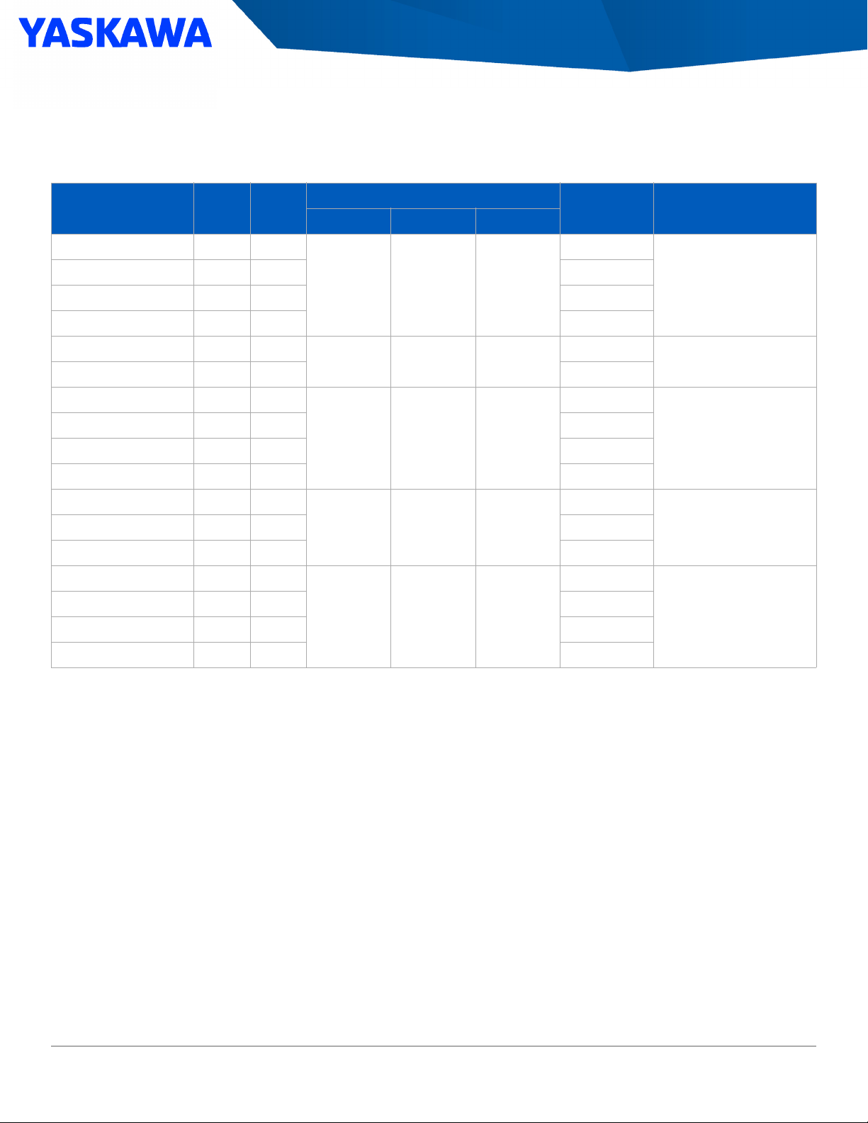
Section: GA800 Configured Package Specifications
Type 1 Configured Package Dimensions
Table 48: 240 V, Type 1, Normal Duty
Type 1 Configured (ND)
G8C1 . .
Amps
Nominal
HP
Physical Dimensions (in.)
H W D
Weight
1
(lb)
Drawing Number
2
A004 4.2 1
A006 6.8 2 83
A009 9.6 3 86
A015 15.2 5 89
A022 22 7.5
A028 28 10 113
A042 42 15
A054 54 20 154
A068 68 25 160
A080 80 30 165
A104 104 40
A154 154 60 325
A192 192 75
A248 248 100 785
A312 312 125 840
A360 360 150 926
1. This data represents the average drive package weight only, not shipping weight.
2. The drawings are available in pdf, .doc., and .dwg formats. Click the Mechanical Drawings link available on the GA800 Product Details page at www.yaskawa.com.
28.8 18.3 14.3
34.8 20.8 14.4
39.8 25.8 15.9
50.8 32.9 18.3
85.7 41.3 34.1
81
DD.G.1.W1.01
110
DD.G.1.W2.01
146
DD.G.1.W3.01
260
DD.G.1.W4.01A130 130 50 274
705
DD.G.1.F1.01
68 Yaskawa America, Inc., GA800 Selection Guide SL.GA800.01

Section: GA800 Configured Package Specifications
Table 49: 240 V, Type 1, Heavy Duty
Type 1 Configured (HD)
G8C4 . .
Amps
Nominal
HP
Physical Dimensions (in.)
H W D
Weight
1
(lb)
Drawing Number
2
A004 4.2 1
A006 6.8 2 83
A009 9.6 3 86
A015 15.2 5
A022 22 7.5
A028 28 10
A042 42 15 122
A054 54 20
A068 68 25 161
A080 80 30
A104 104 40 263
A130 130 50 323
A154 154 60 330
A192 192 75
A248 248 100 788
A312 312 125 896
A360 360 150 969
1. This data represents the average drive package weight only, not shipping weight.
2. The drawings are available in .pdf, .doc., and .dwg formats. Click the Mechanical Drawings link available on the GA800 Product Details page at www.yaskawa.com.
28.8 18.3 14.3
34.8 20.8 14.4
39.8 25.8 15.9
50.8 32.9 18.3
85.7 41.3 34.1
81
DD.G.1.W1.01
89
110
DD.G.1.W2.01
156
DD.G.1.W3.01
254
DD.G.1.W4.01
757
DD.G.1.F1.01
GA800 Selection Guide SL.GA800.01, Yaskawa America, Inc. 69
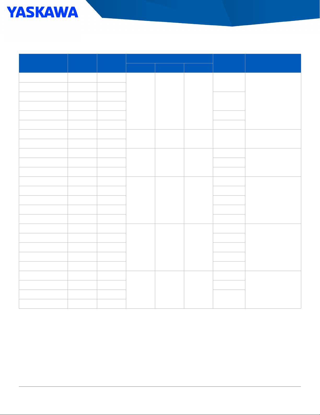
Table 50: 480 V, Type 1, Normal Duty
Type 1 Configured (ND)
G8C1 . .
Amps
Section: GA800 Configured Package Specifications
Nominal
HP
Physical Dimensions (in.)
H W D
Weight
1
(lb)
Drawing Number
2
B002 2.1 1
B003 3.4 2
B004 4.8 3
B007 7.6 5
B011 11 7.5 86
B014 14 10 89
B021 21 15
B027 27 20
B034 34 25
B052 52 40 168
B065 65 50
B077 77 60 259
B096 96 75 276
B124 124 100 306
B156 156 125 319
B180 180 150
28.8 18.3 14.3
34.8 20.8 14.4 118 DD.G.1.W2.01
39.8 25.8 15.9
50.8 32.9 18.3
80
84
147
246
785
DD.G.1.W1.01
DD.G.1.W3.01B040 40 30 153
DD.G.1.W4.01
B240 240 200 812
B302 302 250 842
B361 361 300 1010
B414 414 350 1065
B477 477 400
B515 515 450 1566
B590 590 500
B720 720 600
1. This data represents the average drive package weight only, not shipping weight.
2. The drawings are available in .pdf, .doc., and .dwg formats. For additional formats, click the Mechanical Drawings link available on the GA800 Product Details page at
www.yaskawa.com.
85.7 41.3 34.1
1511
87.1 69.8 33.3
1630
DD.G.1.F1.01
DD.G.1.F2.01
70 Yaskawa America, Inc., GA800 Selection Guide SL.GA800.01

Section: GA800 Configured Package Specifications
Table 51: 480 V, Type 1, Heavy Duty
Type 1 Configured (HD)
G8C4 . .
Amps
Nominal
HP
Physical Dimensions (in.)
H W D
Weight
1
(lb)
Drawing Number
2
B002 2.1 1
B003 3.4 2
B004 4.8 3
B007 7.6 5
B011 11 7.5
B014 14 10
B021 21 15
B027 27 20
B034 34 25
B040 40 30 164
B052 52 40
B065 65 50 256
B077 77 60 266
B096 96 75 301
B124 124 100 308
B156 156 125
B180 180 150 771
28.8 18.3 14.3
34.8 20.8 14.4 120 DD.G.1.W2.01
39.8 25.8 15.9
50.8 32.9 18.3
80
85
90
150
242
761
DD.G.1.W1.01
DD.G.1.W3.01
DD.G.1.W4.01
B240 240 200 818
B302 302 250 951
B361 361 300 1021
B414 414 350
B477 477 400 1531
B515 515 450
B590 590 500
1. This data represents the average drive package weight only, not shipping weight.
2. The drawings are available in .pdf, .doc., and .dwg formats. For additional formats, click the Mechanical Drawings link available on the GA800 Product Details page at
www.yaskawa.com.
85.7 41.3 34.1
1487
87.1 69.8 33.3
1608
DD.G.1.F1.01
DD.G.1.F2.01
GA800 Selection Guide SL.GA800.01, Yaskawa America, Inc. 71

Section: GA800 Configured Package Specifications
Type 12 Configured Package Dimensions
Table 52: 240 V, Type 12, Normal Duty
Type 12 Configured (ND)
G8C2 . .
A004 4.2 1
A006 6.8 2
A009 9.6 3
A015 15.2 5
A022 22 7.5
A028 28 10
Amps
Nominal
HP
Physical Dimensions (in.)
H W D
29.0 18.0 18.4 110 DD.G.12.W1.01
35.0 20.5 18.4 134 DD.G.12.W2.01
Weight
1
(lb)
Drawing Number
2
A042 42 15
A054 54 20 183
40.0 25.5 18.4
A068 68 25 187
A080 80 30 192
A104 104 40
51.0 32.6 22.5
A154 154 60 333
A192 192 75
A248 248 100 645
85.7 41.3 34.2
A312 312 125 698
A360 360 150 800
1. This data represents the average drive package weight only, not shipping weight.
2. The drawings are available in .pdf, .doc., and .dwg formats. For additional formats, click the Mechanical Drawings link available on the GA800 Product Details page at
www.yaskawa.com.
170
DD.G.12.W3.01
262
DD.G.12.W4.01A130 130 50 277
545
DD.G.12.F1.01
72 Yaskawa America, Inc., GA800 Selection Guide SL.GA800.01

Section: GA800 Configured Package Specifications
Table 53: 240V, Type 12, Heavy Duty
Type 12 Configured (HD)
G8C5 . .
A004 4.2 1
A006 6.8 2
Amps
Nominal
HP
Physical Dimensions (in.)
H W D
Weight
1
(lb)
Drawing Number
2
A009 9.6 3
A015 15.2 5
A022 22 7.5
A028 28 10
A042 42 15 142
A054 54 20
A068 68 25 188
A080 80 30
A104 104 40 273
A130 130 50 332
A154 154 60 338
A192 192 75
A248 248 100 684
A312 312 125 788
29.0 18.0 18.4 110 DD.G.12.W1.01
129
35.0 20.5 18.4
184
40.0 25.5 18.4
255
51.0 32.6 22.5
636
85.7 41.3 34.2
DD.G.12.W2.01
DD.G.12.W3.01
DD.G.12.W4.01
DD.G.12.F1.01
A360 360 150 822
1. This data represents the average drive package weight only, not shipping weight.
2. The drawings are available in .pdf, .doc., and .dwg formats. For additional formats, click the Mechanical Drawings link available on the GA800 Product Details page at
www.yaskawa.com.
GA800 Selection Guide SL.GA800.01, Yaskawa America, Inc. 73

Table 54: 480 V, Type 12, Normal Duty
Type 12 Configured (ND)
G8C2 . .
B002 2.1 1
B003 3.4 2
Amps
Section: GA800 Configured Package Specifications
Nominal
HP
Physical Dimensions (in.)
H W D
Weight
1
(lb)
Drawing Number
2
B004 4.8 3
B007 7.6 5
B011 11 7.5
B014 14 10
B021 21 15
B027 27 20
B034 34 25
B052 52 40 194
B065 65 50
B077 77 60 265
B096 96 75 279
B124 124 100 313
B156 156 125 327
B180 180 150
B240 240 200 676
B302 302 250 706
29.0 18.0 18.4 110 DD.G.12.W1.01
35.0 20.5 18.4 139 DD.G.12.W2.01
172
40.0 25.5 18.4
246
51.0 32.6 22.5
643
85.7 41.3 34.2
DD.G.12.W3.01B040 40 30 180
DD.G.12.W4.01
DD.G.12.F1.01
B361 361 300 873
B414 414 350 932
B477 477 400
B515 515 450 1441
B590 590 500 1494
B720 720 600 1520
1. This data represents the average drive package weight only, not shipping weight.
2. The drawings are available in .pdf, .doc., and .dwg formats. For additional formats, click the Mechanical Drawings link available on the GA800 Product Details page at.
www.yaskawa.com.
74 Yaskawa America, Inc., GA800 Selection Guide SL.GA800.01
87.1 69.8 33.3
1384
DD.G.12.F2.01

Section: GA800 Configured Package Specifications
Table 55: 480 V, Type 12, Heavy Duty
Type 12 Configured (HD)
G8C5 . .
B002 2.1 1
B003 3.4 2
Amps
Nominal
HP
Physical Dimensions (in.)
H W D
Weight
1
(lb)
Drawing Number
2
B004 4.8 3
B007 7.6 5
B011 11 7.5
B014 14 10
B021 21 15
B027 27 20
B034 34 25
B040 40 30 189
B052 52 40
B065 65 50 292
B077 77 60 300
B096 96 75 321
B124 124 100 326
B156 156 125
B180 180 150 658
B240 240 200 755
B302 302 250 810
29.0 18.0 18.4 110 DD.G.12.W1.01
35.0 20.5 18.4 140 DD.G.12.W2.01
177
40.0 25.5 18.4
264
51.0 32.6 22.5
647
85.7 41.1 34.2
DD.G.12.W3.01
DD.G.12.W4.01
DD.G.12.F1.01
B361 361 300 865
B414 414 350
B477 477 400 1449
B515 515 450 1488
B590 590 500 1531
1. This data represents the average drive package weight only, not shipping weight.
2. The drawings are available in .pdf, .doc., and .dwg formats. For additional formats, click the Mechanical Drawings link available on the GA800 Product Details page at
www.yaskawa.com.
GA800 Selection Guide SL.GA800.01, Yaskawa America, Inc. 75
87.1 69.8 33.3
1342
DD.G.12.F2.01

Section: GA800 Configured Package Specifications
Type 3R Configured Package Dimensions
Table 56: 240 V, Type 3R, Normal Duty
Type 3R Configured (ND)
G8C3 . .
A004 4.2 1
Amps
Nominal
HP
Physical Dimensions (in.)
H W D
Weight
1
(lb)
Drawing Number
2
A006 6.8 2
29.0 21.2 21.5
A009 9.6 3
A015 15.2 5 150
A022 22 7.5
35.0 23.7 21.5 175
A028 28 10
A042 42 15
A054 54 20 235
40.0 28.7 21.5
A068 68 25
A080 80 30
A104 104 40
A130 130 50 375
A154 154 60 400
A192 192 75
A248 248 100 950
A312 312 125 1000
51.0 39.0 21.5
92.6 41.2 48.7
140
225
250
350
875
DD.G.3R.W1.01
DD.G.3R.W2.01
DD.G.3R.W3.01
DD.G.3R.W4.01
DD.G.3R.F1.01
3
3
3
3
A360 360 150 1100
1. This data represents the average drive package weight only, not shipping weight.
2. The drawings are available in .pdf, .doc., and .dwg formats. For additional formats, click the Mechanical Drawings link available on the GA800 Product Details page at
www.yaskawa.com.
3. Optional Freestanding Leg kits are available for Type 3R enclosures.
76 Yaskawa America, Inc., GA800 Selection Guide SL.GA800.01

Section: GA800 Configured Package Specifications
Table 57: 240 V, Type 3R, Heavy Duty
Type 3R Configured (HD)
G8C6 . .
A004 4.2 1
Amps
Nominal
HP
Physical Dimensions (in.)
H W D
Weight
1
(lb)
Drawing Number
2
A006 6.8 2
A009 9.6 3
29.0 21.2 21.5
140
A015 15.2 5
150
A022 22 7.5
A028 28 10
175
35.0 23.7 21.5
A042 42 15 185
A054 54 20
40.0 28.7 21.5 240
A068 68 25
A080 80 30
350
A104 104 40 375
51.0 39.0 21.5
A130 130 50 400
A154 154 60 415
A192 192 75
925
A248 248 100 950
92.6 41.2 48.7
A312 312 125 1075
DD.G.3R.W1.01
DD.G.3R.W2.01
DD.G.3R.W3.01
DD.G.3R.W4.01
DD.G.3R.F1.01
3
3
3
3
A360 360 150 1150
1. This data represents the average drive package weight only, not shipping weight.
2. The drawings are available in .pdf, .doc., and .dwg formats. For additional formats, click the Mechanical Drawings link available on the GA800 Product Details page at
www.yaskawa.com.
3. Optional Freestanding Leg kits are available for Type 3R enclosures.
GA800 Selection Guide SL.GA800.01, Yaskawa America, Inc. 77

Table 58: 480 V, Type 3R, Normal Duty
Type 3R Configured (ND)
G8C3 . .
B002 2.1 1
B003 3.4 2
Amps
Section: GA800 Configured Package Specifications
Nominal
HP
Physical Dimensions (in.)
H W D
Weight
1
(lb)
Drawing Number
2
B004 4.8 3
140
29.0 21.2 21.5
B007 7.6 5
B011 11 7.5
B014 14 10 150
B021 21 15
35.0 23.7 21.5 175
B027 27 20
B034 34 25
225
40.0 28.7 21.5
B040 40 30 235
B052 52 40
325
B065 65 50 350
B077 77 60
51.0 39.0 21.5
375
B096 96 75
B124 124 100 410
B156 156 125 425
B180 180 150
950
B240 240 200 975
B302 302 250 1000
92.6 41.2 48.7
DD.G.3R.W1.01
DD.G.3R.W2.01
DD.G.3R.W3.01
DD.G.3R.W4.01
DD.G.3R.F1.01
3
3
3
3
B361 361 300 1150
B414 414 350 1175
B477 477 400
1400
B515 515 450 1500
94.0 66.3 50.0
DD.G.3R.F2.01
B590 590 500 1550
B720 720 600 1575
1. This data represents the average drive package weight only, not shipping weight.
2. The drawings are available in .pdf, .doc., and .dwg formats. For additional formats, click the Mechanical Drawings link available on the GA800 Product Details page at
www.yaskawa.com.
3. Optional Freestanding Leg kits are available for Type 3R enclosures.
78 Yaskawa America, Inc., GA800 Selection Guide SL.GA800.01
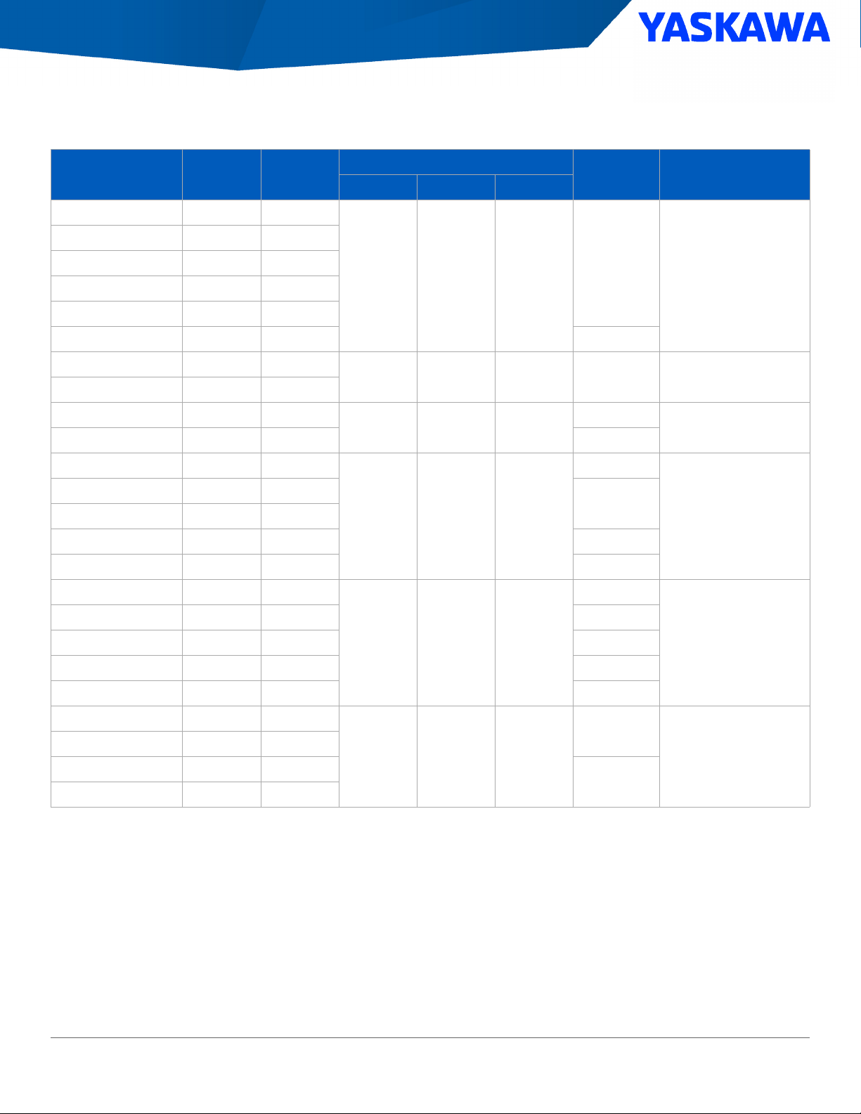
Section: GA800 Configured Package Specifications
Table 59: 480 V, Type 3R, Heavy Duty
Type 3R Configured (HD)
G8C6 . .
B002 2.1 1
B003 3.4 2
Amps Nominal HP
Physical Dimensions (in.)
H W D
Weight
1
(lb)
Drawing Number
2
B004 4.8 3
140
29.0 21.2 21.5
B007 7.6 5
B011 11 7.5
B014 14 10 150
B021 21 15
35.0 23.7 21.5 185
B027 27 20
B034 34 25
225
40.0 28.7 21.5
B040 40 30 240
B052 52 40
330
B065 65 50
375
B077 77 60
51.0 39.0 21.5
B096 96 75 400
B124 124 100 415
B156 156 125
925
B180 180 150 950
B240 240 200 975
92.6 41.2 48.7
B302 302 250 1125
DD.G.3R.W1.01
DD.G.3R.W2.01
DD.G.3R.W3.01
DD.G.3R.W4.01
DD.G.3R.F1.01
3
3
3
3
B361 361 300 1175
B414 414 350
1400
B477 477 400
94.0 66.3 50.0
DD.G.3R.F2.01
B515 515 450
1500
B590 590 500
1. This data represents the average drive package weight only, not shipping weight.
2. The drawings are available in .pdf, .doc., and .dwg formats. For additional formats, click the Mechanical Drawings link available on the GA800 Product Details page at
www.yaskawa.com.
3. Optional Freestanding Leg kits are available for Type 3R enclosures.
GA800 Selection Guide SL.GA800.01, Yaskawa America, Inc. 79

Section: GA800 Configured Package Specifications
Additional Configured Package Options
Table 60: Type 1, Type 12, Type 3R 240 V, 480 V Configured Package
Additional Installed Power Options (valid for all voltage and power ratings)
P Code Description
N Noise Filter
2 Surge Suppressor (only for Type 3R)
3 Cabinet Space Heater (thermostatically controlled, only for Type 3R)
Table 61: Communication and Control Options
Installed Control Options (applies to all voltage and power ratings)
1
Group
Group 1:
Select None
or One
Group 2
Group 3:
Select None or One
Group 4:
Select None, Any, or All
C Code Description
C PROFINET dual port (SI-EP3)
D EitherNet/IP dual port (SI-EN3D)
G DeviceNet (SI-N3)
HPROFIBUS-DP (SI-P3)
Q Modbus/TCP dual port (SI-EM3D)
A Analog Input (provides 3 additional inputs) (AI-A3)
F Digital Input (provides 16 additional inputs) (DI-A3)
N Analog Monitor (provides 2 additional outputs) (AO-A3)
E Digital Output (provides 8 additional outputs) (DO-A3)
X Incremental Encoder Interface (line driver type) (PG-X3)
V 120 V Digital Interface (converts standard inputs)
YHOA Switch
ZSpeed Pot
M Lockable Viewing Window (covers door mounted operator devices, only for Type 3R)
1. If no option from Group 1 or Group 3 is selected, then both options from Group 2 may be selected.
If no option from Group 1 is selected, then ALL options from Group 2 and Group 3 may be selected.
Select anything from Group 4, regardless of other group selections.
Table 62: Special Options
Installed Special Options (applies to all voltage and power ratings)
S Code Description
B Bluetooth Keypad Upgrade (comes with standard keypad if not selected)
80 Yaskawa America, Inc., GA800 Selection Guide SL.GA800.01

Section: GA800 Configured Package Specifications
Freestanding Leg Kit, Type 3R
This option allows all the Type 3R wall-mount enclosures to be mounted on legs so that the control can be freestanding and off the ground.
Any kit can be used on the wall-mount enclosures. Floor-mount enclosures come standard with freestanding legs.
Table 63: Freestanding Leg Kits
Part Number Description
UUX000923 12 inch height (for all Type 3R wall mount sizes)
UUX001656 18 inch height (for all Type 3R wall mount sizes)
UUX000924 30 inch height (for all Type 3R wall mount sizes)
GA800 Selection Guide SL.GA800.01, Yaskawa America, Inc. 81


GA800 Series
Selection Guide
YASKAWA AMERICA, INC.
2121 Norman Drive S.
Waukegan, IL 60085 USA
1-800-YASKAWA (927-5292)
WWW.YASKAWA.COM
DRIVE CENTER
(INVERTER PLANT)
13-1 Nishimiyaichi 2 Chome,
Yukuhashi, Fukuoka
824-8511 Japan
Tel: +81-930-23-1401
WWW.YASKAWA.CO.JP
In the event that the end user of this product is to be the military and said product is to be employed in any
weapons systems or the manufacture thereof, the export will fall under the relevant regulations as stipulated
in the Foreign Exchange and Foreign Trade Regulations. Therefore, be sure to follow all procedures and
submit all relevant documentation according to any and all rules, regulations and laws that may apply.
Specifications are subject to change without notice for ongoing product modifications and improvements.
© 2010-2019 YASKAWA America, Inc.
YASKAWA EUROPE GmbH
Hauptstr. 185
65760 Eschborn, Germany
Fon: +49 (0)6196 569-500
WWW.YASKAWA.EU.COM
YASKAWA ELÉTRICO
DO BRASIL LTDA.
Av. Piraporinha, 777
Vila Nogueira Diadema
São Paulo, Brasil 09950-000
Pabx: +55 11 3585-1100
WWW.YASKAWA.COM.BR
YASKAWA AMERICA, INC.
SL.GA800.01
SL.GA800.01
Revision: B-1
February 2020
Published in USA
 Loading...