

Page 1
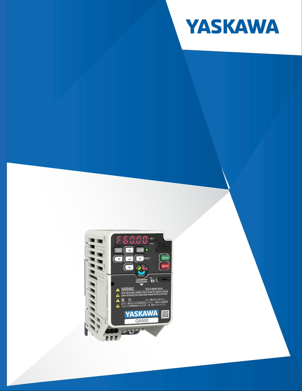
GA500
Industrial AC Microdrive
Selection Guide
Catalog Code: G
240 V: Single 240 V: Three - Phase,1/6 to 30 HP
480 V: Three - Phase,1/2 to 40 HP
A50Uxxxxxxxx
Phase, 1/6 to 5 HP
Page 2

Copyright © 2020 YASKAWA AMERICA, INC.
All rights reserved. No part of this publication may be reproduced, stored in a retrieval system, or
transmitted, in any form or by any means, mechanical, electronic, photocopying, recording, or otherwise,
without the prior written permission of Yaskawa. No patent liability is assumed with respect to the use of the
information contained herein. Moreover, because Yaskawa is constantly striving to improve its high-quality
products, the information contained in this manual is subject to change without notice. Every precaution has
been taken in the preparation of this manual. Y
Neither is any liability assumed for damages resulting from the use of the information contained in this
publication.
askawa assumes no responsibility for errors or omissions.
Page 3

Table of Contents
Preface . . . . . . . . . . . . . . . . . . . . . . . . . . . . . . . . . . . . . . . . . . . . . . . . . . . . . . . . . . . . . . . . . . . . . . . . . 2
Additional Resources . . . . . . . . . . . . . . . . . . . . . . . . . . . . . . . . . . . . . . . . . . . . . . . . . . . . . . . . . 2
GA500 AC Microdrives . . . . . . . . . . . . . . . . . . . . . . . . . . . . . . . . . . . . . . . . . . . . . . . . . . . . . . . . . . . . . 3
Drive Selection . . . . . . . . . . . . . . . . . . . . . . . . . . . . . . . . . . . . . . . . . . . . . . . . . . . . . . . . . . . . . . 3
Dimensions & Weights . . . . . . . . . . . . . . . . . . . . . . . . . . . . . . . . . . . . . . . . . . . . . . . . . . . . . . . . . . . . . . 6
IP20/Protected Chassis Dimensions . . . . . . . . . . . . . . . . . . . . . . . . . . . . . . . . . . . . . . . . . . . . . . 6
Drive Specifications . . . . . . . . . . . . . . . . . . . . . . . . . . . . . . . . . . . . . . . . . . . . . . . . . . . . . . . . . . . . . . . . 9
Network Communication Options . . . . . . . . . . . . . . . . . . . . . . . . . . . . . . . . . . . . . . . . . . . . . . . . . . . . 10
Keypad and Accessories . . . . . . . . . . . . . . . . . . . . . . . . . . . . . . . . . . . . . . . . . . . . . . . . . . . . . . . . . . . 11
Enclosure Adapters and Kits . . . . . . . . . . . . . . . . . . . . . . . . . . . . . . . . . . . . . . . . . . . . . . . . . . . . . . . . 13
IP20/UL Type 1 Adapters . . . . . . . . . . . . . . . . . . . . . . . . . . . . . . . . . . . . . . . . . . . . . . . . . . . . . 13
External Heatsink Adapters . . . . . . . . . . . . . . . . . . . . . . . . . . . . . . . . . . . . . . . . . . . . . . . . . . . . 16
DIN Rail Mounting Adapters . . . . . . . . . . . . . . . . . . . . . . . . . . . . . . . . . . . . . . . . . . . . . . . . . . . 18
Power Options. . . . . . . . . . . . . . . . . . . . . . . . . . . . . . . . . . . . . . . . . . . . . . . . . . . . . . . . . . . . . . . . . . . 19
DC Bus Reactors . . . . . . . . . . . . . . . . . . . . . . . . . . . . . . . . . . . . . . . . . . . . . . . . . . . . . . . . . . . 20
AC Input Reactors . . . . . . . . . . . . . . . . . . . . . . . . . . . . . . . . . . . . . . . . . . . . . . . . . . . . . . . . . . 25
AC Output Reactors . . . . . . . . . . . . . . . . . . . . . . . . . . . . . . . . . . . . . . . . . . . . . . . . . . . . . . . . . 28
AC Open Reactor Dimensions . . . . . . . . . . . . . . . . . . . . . . . . . . . . . . . . . . . . . . . . . . . . . . . . . 31
Enclosed AC Reactor Dimensions. . . . . . . . . . . . . . . . . . . . . . . . . . . . . . . . . . . . . . . . . . . . . . . 33
Dynamic Braking Options . . . . . . . . . . . . . . . . . . . . . . . . . . . . . . . . . . . . . . . . . . . . . . . . . . . . . 36
10% Dynamic Braking Options . . . . . . . . . . . . . . . . . . . . . . . . . . . . . . . . . . . . . . . . . . . . . . . . . 36
3% Dynamic Braking Options . . . . . . . . . . . . . . . . . . . . . . . . . . . . . . . . . . . . . . . . . . . . . . . . . . 39
R1000 Regenerative Systems . . . . . . . . . . . . . . . . . . . . . . . . . . . . . . . . . . . . . . . . . . . . . . . . . . 41
R1000 External Heatsink Kits . . . . . . . . . . . . . . . . . . . . . . . . . . . . . . . . . . . . . . . . . . . . . . . . . . 43
Single Phase Converter. . . . . . . . . . . . . . . . . . . . . . . . . . . . . . . . . . . . . . . . . . . . . . . . . . . . . . . 45
GA500 Drive Derating . . . . . . . . . . . . . . . . . . . . . . . . . . . . . . . . . . . . . . . . . . . . . . . . . . . . . . . . . . . . . 47
Carrier Frequency . . . . . . . . . . . . . . . . . . . . . . . . . . . . . . . . . . . . . . . . . . . . . . . . . . . . . . . . . . . 47
Altitude . . . . . . . . . . . . . . . . . . . . . . . . . . . . . . . . . . . . . . . . . . . . . . . . . . . . . . . . . . . . . . . . . . . 50
Ambient Temperature . . . . . . . . . . . . . . . . . . . . . . . . . . . . . . . . . . . . . . . . . . . . . . . . . . . . . . . . 50
Watt Loss . . . . . . . . . . . . . . . . . . . . . . . . . . . . . . . . . . . . . . . . . . . . . . . . . . . . . . . . . . . . . . . . . . . . . . 51
Watt Loss without EMC Filter . . . . . . . . . . . . . . . . . . . . . . . . . . . . . . . . . . . . . . . . . . . . . . . . . . 51
Watt Loss with EMC Filter . . . . . . . . . . . . . . . . . . . . . . . . . . . . . . . . . . . . . . . . . . . . . . . . . . . . . 53
Branch Circuit Protection. . . . . . . . . . . . . . . . . . . . . . . . . . . . . . . . . . . . . . . . . . . . . . . . . . . . . . . . . . . 55
Yaskawa America, Inc., SL.GA500.01. GA500 AC Microdrive Selection Guide 1
Page 4
Preface
This book is intended to help easily locate component information for Yaskawa GA500 Drives and optional accessories.
The intended users for this document are Yaskawa sales personnel, distributors, and partners.
This book may describe trademarked equipment, which is the property of other companies. These trademarks are the property of the registered owner companies and may include the following:
DeviceNet ™ , trademark of ODVA PROFIBUS®, trademark of PROFIBUS International.
Modbus®, trademark of Schneider Automation, Inc. PROFINET®, trademark of PROFIBUS International.
EtherCAT, trademark of Beckhoff Automation GmbH, Germany Ethernet/IP, trademark of ODVA
MECHATROLINK - I, II, III, trademarks of MECHATROLINK Members Association
Other Documents and Manuals are available to support special use or installation of this product. These documents may be provided with the
product or upon request. Contact Yaskawa America, Inc. or visit www.yaskawa.com.
Additional Resources
The Yaskawa.com web site has the most current information for all Yaskawa products. When researching product specifications or features
the Yaskawa web site is the best resource to use. Some useful links for the GA500 drive product are listed here and throughout this document:
Resource Links
GA500 Price Book GA500 Flyer
GA500 Brochure GA500 Product Transition Guide
2 GA500 AC Microdrive Selection Guide, SL.GA500.01. Yaskawa America, Inc.
Page 5
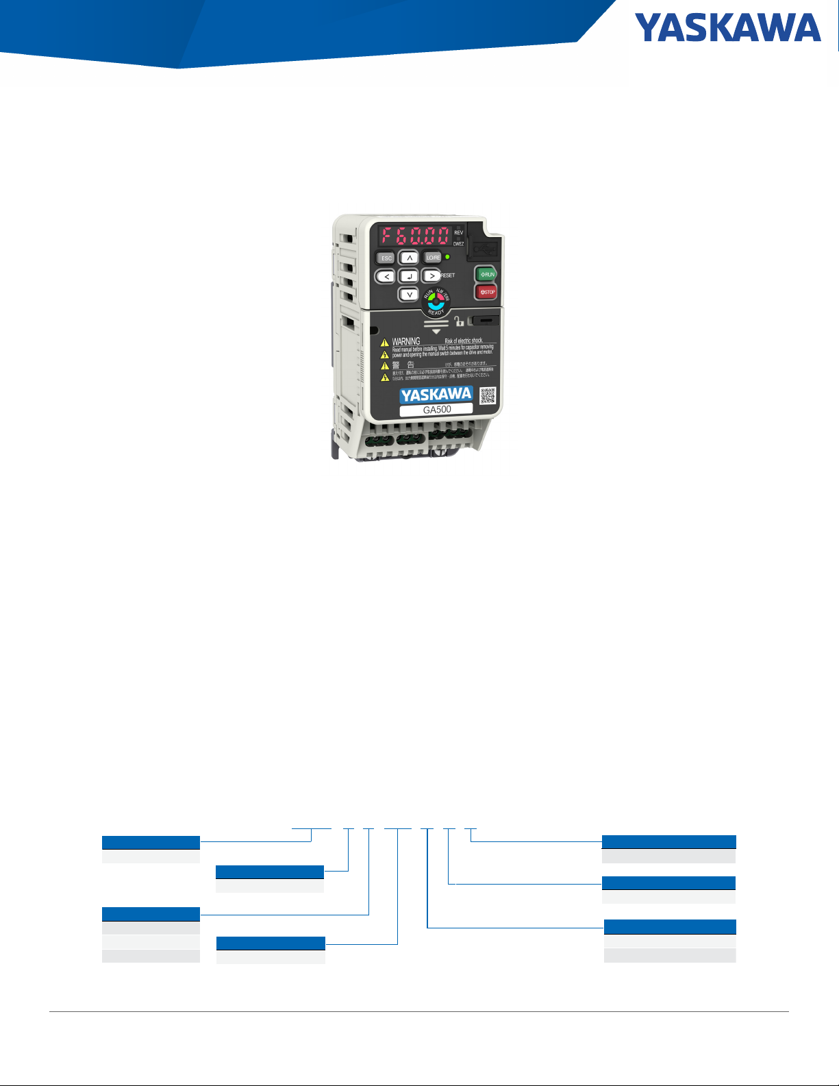
Section: GA500 AC Microdrives
*H[HSVN*VKL+LZPNUH[PVU
,U]PYVUTLU[HS:WLJ
.(<()(
=VS[HNL*SHZZ
)!=:PUNSLWOHZL
!=;OYLLWOHZL
!=;OYLLWOHZL
7YVK\J[:LYPLZ
.(:LYPLZ
9H[LK6\[W\[*\YYLU[
:LL9H[PUNZ;HISL
,4*-PS[LY6W[PVU
(!5VI\PS[PUMPS[LY
,!)\PS[PU,4*MPS[LY
,UJSVZ\YL
)!077YV[LJ[LK*OHZZPZ
9LNPVU*VKL
<!(TLYPJHZ
(!:[HUKHYK
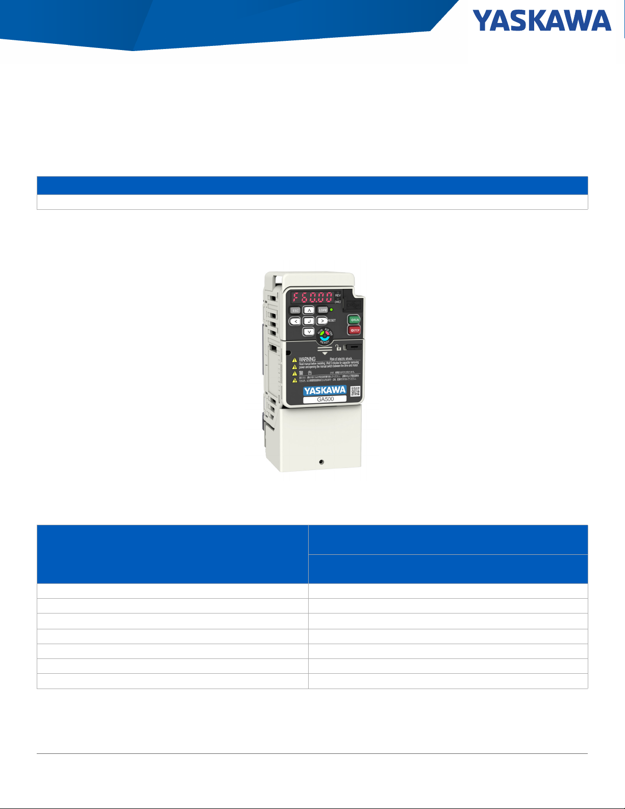
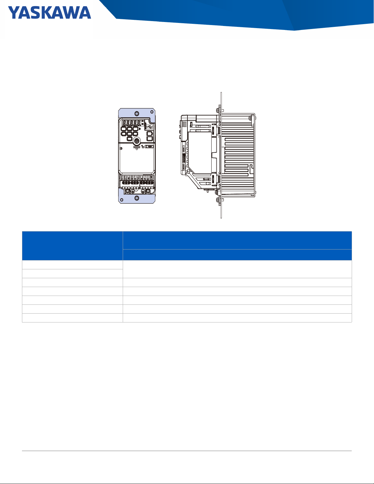
GA500 AC Microdrives
Drive Selection
The GA500 precisely controls induction, permanent magnet, and synchronous reluctance motors providing versatility to run a variety of
applications with just one drive. The times of complex motor setup are over. With the new EZ Vector mode, the GA500 can run all of these
motor types without comprehensive tuning.
• Time and Cost Savings
• Easy Installation and System Integration
Standard (IP20/Protected Chassis) drives are intended for clean environments and can be mounted 3 different ways as follows:
1) In a separate enclosure with heatsink internal. Extra mounting brackets are not required.
2) In a separate enclosure with heatsink external. Refer to Enclosure Adapters and Kits for drives requiring extra mounting brackets.
3) Mounted without an enclosure. UL Type 1 Adapters must be used when mounting the drive without an enclosure.
The GA500 offers two separate performance ratings; Heavy Duty and Normal Duty. Heavy Duty is capable of creating more powerful torque,
while Normal Duty allows the drive to operate a larger motor.
• Easy to Use - Easy to Maintain
• More Reliable - Easier Machine Design
Yaskawa America, Inc., GA500 AC Microdrive Selection Guide, SL.GA500.01 3
Page 6
Section: GA500 AC Microdrives
Table 1: 240 V, Single-Phase Input, IP20/Protected Chassis Drives, 1/6 to 5 HP
Normal Duty Output Heavy Duty Output
Standard Drives
1
Built-In EMC Drives
2
HP Amps HP Amps
1/6 1.2 1/6 0.8 B001ABA B001EBA
1/4 1.9 1/4 1.6 B002ABA B002EBA
3/4 3.5 1/2 3 B004ABA B004EBA
1.5 6 1 5 B006ABA B006EBA
3 9.6 2 8 B010ABA B010EBA
3 12.2 3 11 B012ABA B012EBA
N/A N/A 5 17.6 B018ABA B018EBA
1. Standard (IP20/Protected Chassis) Drives are intended for clean environments, and can be mounted 3 different ways as follows:
A) In a separate enclosure with heatsink internal (no extra mounting brackets required)
B) In a se
C) Without a
2. E: Built-in EMC Filter: C1: 200 V Single-Phase, C3: 200 V Three-Phase, C2: 400 V Three-Phase
parate enclosure with heatsink external. See External Heatsink Adapters for sizes requiring extra mounting brackets
separate enclosure, all sizes require UL Type 1 Adapters (see UL Type 1 Adapters)
Catalog Code
GA50U…
Table 2: 240 V, Three-Phase Input, IP20/Protected Chassis Drives, 1/6 to 30 HP
Normal Duty Output Heavy Duty Output
HP Amps HP Amps
1/6 1.2 1/6 0.8 2001ABA 2001EBA
1/4 1.9 1/4 1.6 2002ABA 2002EBA
3/4 3.5 1/2 3 2004ABA 2004EBA
1.5 6 1 5 2006ABA 2006EBA
3 9.6 2 8 2010ABA 2010EBA
4 12.2 3 11 2012ABA 2012EBA
7.5 21 5 17 2021ABA 2021EBA
10 30 7.5 25 2030ABA 2030EBA
15 42 10 33 2042ABA 2042EBA
20 56 15 47 2056ABA 2056EBA
25 70 20 60 2070ABA 2070EBA
30 82 25 75 2082ABA 2082EBA
Standard Drives
Catalog Code
GA50U…
1
Built-In EMC Drives
Catalog Code
GA50U…
Catalog Code
GA50U…
2
1. Standard (IP20/Protected Chassis) Drives are intended for clean environments, and can be mounted 3 different ways as follows:
A) In a separate enclosure with heatsink internal (no extra mounting brackets required)
B) In a separate enclosure with heatsink external. See External Heatsink Adapters for sizes requiring extra mounting brackets
C) Without a
2. E: Built-in EMC Filter: C1: 200 V Single-Phase, C3: 200 V Three-Phase, C2: 400 V Three-Phase
4 GA500 AC Microdrive Selection Guide, SL.GA500.01. Yaskawa America, Inc.
separate enclosure, all sizes require UL Type 1 Adapters (see UL Type 1 Adapters)
Page 7
Section: GA500 AC Microdrives
Table 3: 480 V, Three-Phase Input, IP20/Protected Chassis Drive, 1 to 40 HP
Normal Duty Output
HP Amps HP Amps
1/2 1.2 1/2 1.2 4001ABA 4001EBA
1 2.1 3/4 1.8 4002ABA 4002EBA
2 4.1 2 3.4 4004ABA 4004EBA
3 5.4 3 4.8 4005ABA 4005EBA
4 7.1 3 5.6 4007ABA 4007EBA
5 8.9 4 7.3 4009ABA 4009EBA
7.5 11.9 5 9.2 4012ABA 4012EBA
10 17.5 10 14.8 4018ABA 4018EBA
15 23.4 10 18 4023ABA 4023EBA
20 31 15 24 4031ABA 4031EBA
25 38 20 31 4038ABA 4038EBA
30 44 25 39 4044ABA 4044EBA
40 60 30 45 4060ABA 4060EBA
Heavy Duty Output
1
Standard Drives
Catalog Code
GA50U…
2
Built-In EMC Drives
Catalog Code
GA50U…
3
1. Output capacities stated are for conditions of 3 phase input, DC input, and 12 pulse input. See Single Phase Input Drive Selection for single phase capability.
2. Standard (IP20/Protected Chassis) Drives are intended for clean environments, and can be mounted 3 different ways as follows:
A) In a separate enclosure with heatsink internal (no extra mounting brackets required)
B) In a separate enclosure with heatsink external. See External Heatsink Adapters for sizes requiring extra mounting brackets
C) Without a
3. E: Built-in EMC Filter: C1: 200 V Single-Phase, C3: 200 V Three-Phase, C2: 400 V Three-Phase
separate enclosure, all sizes require UL Type 1 Adapters (see UL Type 1 Adapters)
Yaskawa America, Inc., GA500 AC Microdrive Selection Guide, SL.GA500.01 5
Page 8
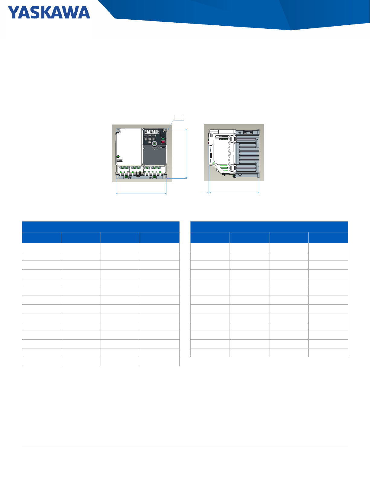
Section: Dimensions & Weights
H
W
3 mm D
A
Frame 1 : 2 holes
Frame 2 - 8 : 4 holes
Dimensions & Weights
IP20/Protected Chassis Dimensions
Figure 1: Drive Dimensions
IP20/Protected Chassis Drive Without EMC Filter
Table 4: Dimensions without EMC Filter Table 5: Dimensions with EMC Filter
Dimensions in (mm)
Frame Height Width Depth
1.1 5.03 (128) 2.67 (68) 2.99 (76)
1.2 5.03 (128) 2.67 (68) 4.64 (118)
1.3 5.03 (128) 2.67 (68) 5.03 (128)
2.1 5.03 (128) 4.25 (108) 5.07 (129)
2.2 5.03 (128) 4.25 (108) 5.07 (129)
2.3 5.03 (128) 4.25 (108) 5.39 (137)
2.4 5.03 (128) 4.25 (108) 6.06 (154)
3.1 5.03 (128) 5.51 (140) 5.62 (143)
3.2 5.03 (128) 5.51 (140) 6.41 (163)
4 5.03 (128) 6.69 (170) 7.08 (180)
5 10.23 (260) 5.51 (140) 5.51 (140)
6 11.81 (300) 7.08 (180) 5.62 (143)
7 13.77 (350) 8.66 (220) 7.36 (187)
8 13.77 (350) 7.48 (190) 8.03 (204)
Frame Height Width Depth
1.1 5.03 (128) 2.67 (68) 4.57 (116)
1.2 5.03 (128) 2.67 (68) 6.22 (158)
1.3 5.03 (128) 2.67 (68) 6.61 (168)
2.1 5.03 (128) 4.25 (108) 6.85 (174)
2.2 5.03 (128) 4.25 (108) 4.96 (126)
2.3 5.03 (128) 4.25 (108) 7.20 (183)
2.4 5.03 (128) 4.25 (108) 7.83 (199)
3.1 5.03 (128) 5.51 (140) 7.60 (193)
3.2 5.03 (128) 5.51 (140) 7.99 (203)
5 10.23 (260) 5.51 (140) 7.72 (196)
6 11.81 (300) 7.08 (180) 7.72 (196)
7 13.77 (350) 8.66 (220) 8.50 (216)
8 13.77 (350) 7.48 (190) 9.88 (251)
Dimensions in (mm)
6 GA500 AC Microdrive Selection Guide, SL.GA500.01. Yaskawa America, Inc.
Page 9

Section: Dimensions & Weights
Table 6: 240 V, Single-Phase Drives
Normal
Duty
(ND)
1/6 1/6 B001 1.2 0.8 1.32 (0.6) 1.1
1/4 1/4 B002 1.9 1.6 1.32 (0.6) 1.1
0.75 0.5 B004 3.5 3 1.98 (0.9) 1.2
1.5 1 B006 6 5 3.3 (1.5) 2.3
3 2 B010 9.6 8 3.3 (1.5) 2.4
3 3 B012 12.2 11 4.84 (2.2) 3.2
N/A 5 B018 N/A 17.6 6.38 (2.9) 4
Heavy
Duty
(HD)
Table 7: 240 V, Three-Phase Drives
Normal Duty
(ND)
1/6 1/6 2001 1.2 0.8 1.54 (0.7) 1.1
1/4 1/4 2002 1.9 1.6 1.54 (0.7) 1.1
3/4 1/2 2004 3.5 3.0 1.76 (0.8) 1.2
1.5 1 2006 6 5.0 2.2 (1) 1.3
3 2 2010 9.6 8.0 4.18 (1.9) 2.1
4 3 2012 12.2 11.0 4.18 (1.9) 2.3
7.5 5 2021 21 17.6 4.84 (2.2) 3.1
10 7.5 2030 30 25.0 7.48 (3.4) 5
15 10 2042 42 33.0 7.48 (3.4) 5
20 15 2056 56 47.0 11 (5) 6
25 20 2070 70 60.0 16.5 (7.5) 7
30 25 2082 82 75.0 18.7 (8.5) 7
Heavy Duty
(HD)
Catalog
Code
GA50U…
Catalog Code
GA50U…
Output Amps
Weight lb (kg) Frame
ND HD
Output Amps
Weight lb (kg) Frame
ND HD
Yaskawa America, Inc., GA500 AC Microdrive Selection Guide, SL.GA500.01 7
Page 10
Table 8: 480 V, Three-Phase Drives
Normal
Duty
(ND)
1/2 1/2 4001 1.2 1.2 1.98 (0.9) 2.2
1 3/4 4002 2.1 1.8 2.2 (1) 2.2
2 2 4004 4.1 3.4 3.3 (1.5) 2.3
3 3 4005 5.4 4.8 3.52 (1.6) 2.4
4 3 4007 7.1 5.6 3.52 (1.6) 2.4
5 4 4009 8.9 7.3 3.52 (1.6) 2.4
7.5 5 4012 11.9 9.2 4.62 (2.1) 3.1
10 10 4018 17.5 14.8 7.26 (3.3) 5
15 10 4023 23.4 18 7.26 (3.3) 5
20 15 4031 31 24 10.34 (4.7) 6
25 20 4038 38 31 10.34 (4.7) 6
30 25 4044 44 39 15.4 (7) 8
40 30 4060 60 45 15.4 (7) 8
Heavy
Duty
(HD)
Section: Dimensions & Weights
Catalog
Code
GA50U…
Output Amps
ND HD
Weight lb (kg) Frame
8 GA500 AC Microdrive Selection Guide, SL.GA500.01. Yaskawa America, Inc.
Page 11

Section: Drive Specifications
Drive Specifications
Power Ratings
Item Specification
Overload Capacity 110%/1 min. (Normal Duty) or 150%/1 min. (Heavy Duty)
200 to 240 VAC, -15 to +10%
Rated Voltage
380 to 480 VAC, -15 to +10%
240 V, Single-phase: 1/6 to 5 HP (0.1 to 3.7 kW)
Capacity Range
Input Frequency 50/60 Hz +/-5%
Output Voltage Accuracy +/-5%
Output Frequency 0 to 590 Hz (special software for up to 1000 Hz)
Control Method V/f, Open Loop (IM/PM), Advanced Open Loop (PM), EZ Open Loop Vector
Motor Control Induction Motor (IM), Permanent Magnet Motor (PM), Synchronous Reluctance Motor (SynRM)
Operating Environment
Item Specification
Ambient Temperature -10 to +50°C (IP20/Protected Chassis), -10 to +40°C (UL Type 1), up to +60°C with derating
Storage Temperature -40 to +70°C (short-term temperature during transportation)
Humidity 95% RH or less (non-condensing)
Altitude Up to 1000 meters without derating, up to 4000 meters with output current and voltage derating
240 V, Three-Phase: 1/6 to 30 HP (0.1 to 22 kW)
480 V, Three-Phase: 1/2 to 40 HP (0.2 to 30 kW)
Shock
10 to 20 Hz: 9.8 m/s
20 to 55 Hz: 5.9 m/s
Protection Design IP20/Protected Chassis Standard, UL Type 1 kit optional
Mounting Side-by-side, horizontal with derating, DIN rail, external heatsink
Conformal Coating (PCB’s) IEC 60721-3-3, Class 3C2 (chemical gases), Class 3S2 (solid particles)
Standards CE, UL, cUL, KC, RCM, EAC, RoHS
Functional Safety STO: IEC/EN61508 SIL3, PLe
Yaskawa America, Inc., GA500 AC Microdrive Selection Guide, SL.GA500.01 9
2
2
Page 12
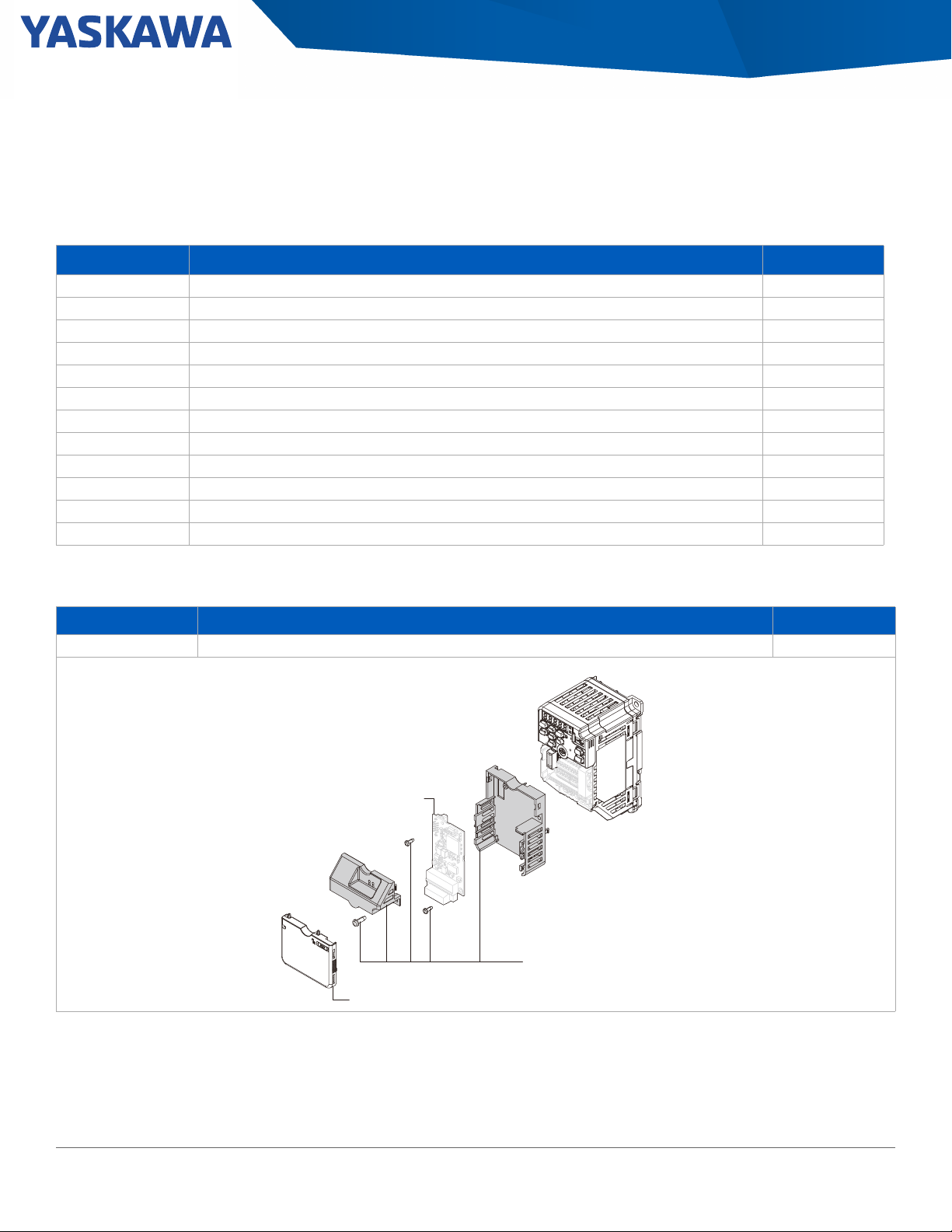
Section: Network Communication Options
6W[PVU*HYK*HYYPLYHUK
4V\U[PUN/HYK^HYL
5L[^VYR6W[PVU*HYK
+YP]L*V]LY
Network Communication Options
These cards, cables, and devices add control functionality to the standard drive. Items are shipped loose and unmounted.
Table 9: Option Cards
1
Option
CANopen® CAN based network option card supporting DS 301 and DSP 402 profiles as specified by CiA. SI-S3
CC-Link Fieldbus network option card managed by the CC-Link Partner Association (CLPA). SI-C3
DeviceNet ™ ODVA compliant option cards to connect to a DeviceNet network. SI-N3
EtherCAT® Option cards to turn the drive into an EtherCAT slave on the network. SI-ES3
Ethernet/IP ™ ODVA compliant option cards to connect to Ethernet/IP. (single port card) SI-EN3
Ethernet/IP dual port ODVA compliant option cards to connect to Ethernet/IP. (dual port card) SI-EN3/D
MECHATROLINK-II Option cards to turn the drive into a M-II node and connect to a high-speed MECHATROLINK-II network. SI-T3
MECHATROLINK-III Option cards to turn the drive into a M-III node and connect to a high-speed MECHATROLINK-III network. SI-ET3
Modbus/TCP Simple and effective solution to connect the drive to a Modbus TCP/IP network. (single port card) SI-EM3
Modbus/TCP dual port Simple and effective solution to connect the drive to a Modbus TCP/IP network. (dual port card) SI-EM3/D
PROFIBUS-DP® PI compliant option cards to connect to a PROFINET network. SI-P3
PROFINET® PI compliant option cards to connect to a PROFIBUS-DP network. SI-EP3
Purpose Catalog Code
1. Use of an option card requires the Option Card Carrier.
Table 10: Option Card Carrier
Option Purpose Catalog Code
Option Card Carrier For use when installing a communication option card on the GA500. JOHB-GA50
10 GA500 AC Microdrive Selection Guide, SL.GA500.01. Yaskawa America, Inc.
Page 13
Section: Keypad and Accessories
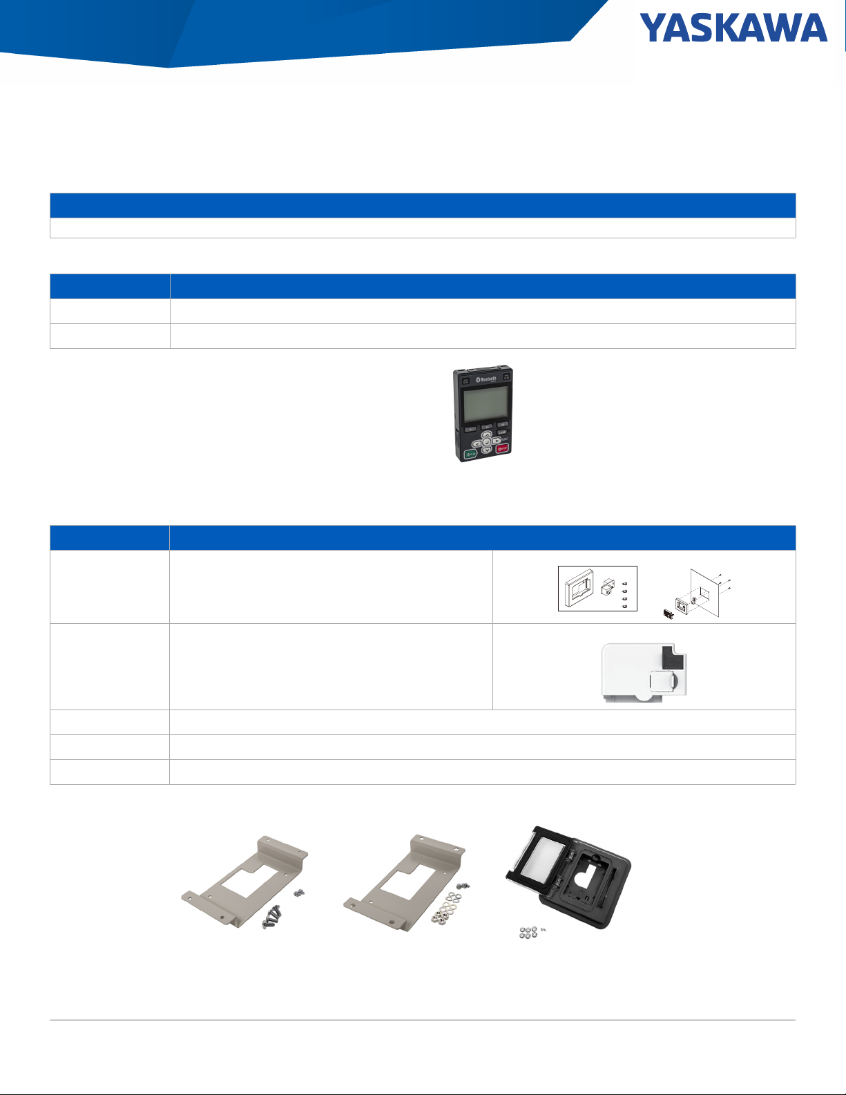
Keypad and Accessories
Additional Information
Keypads, Cables, and Mounting Kits
Table 11: Keypads
Catalog Code Description
JVOP-KPLCA04MEB LCD Keypad (standard, non-Bluetooth)
JVOP-KPLCC04MBB LCD Keypad with Bluetooth
LCD Keypad with Bluetooth
Table 12: Remote Mount Adapters
Catalog Code Description
ZPBA-GA500
JVOP-KPBCH04AAA Blank LED keypad when external mounting GA500 keypad (optional)
900-192-933-001 Type 1 Keypad Panel Mount Kit A (brackets have tapped holes for use with screws) (For use with optional LCD keypad)
900-192-933-002 Type 1 Keypad Panel Mount Kit B (brackets have untapped holes for use with panel studs) (For use with optional LCD keypad)
900-239-230-001 Outdoor Type 12/3/3R Keypad Panel Mount (For use with optional LCD keypad)
UL Type 1 LED keypad mounting kit for standard GA500 keypad
-001 Screw Mount -002 Stud Mount -001 Outdoor Type
Yaskawa America, Inc., GA500 AC Microdrive Selection Guide, SL.GA500.01 11
Page 14
Section: Keypad and Accessories
Table 13: Cables
Catalog Code Description
UWR0051 Keypad Remote Mount Cable - 1 Meter
UWR0052 Keypad Remote Mount Cable - 3 Meter
UWR01258 USB Cable for PC to Drive Communication - 3 Meter
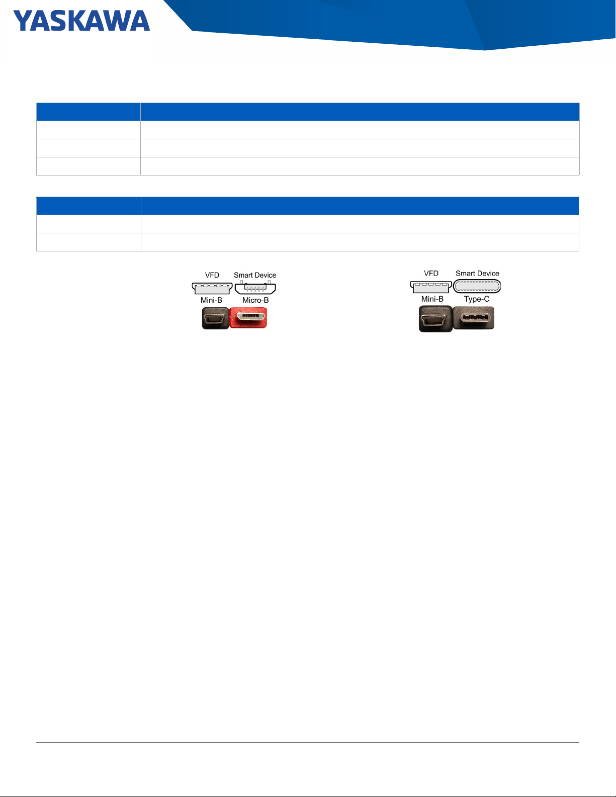
Table 14: Android Mobile Device Interface Cables (for connecting Android device to USB port on drive)
Catalog Code Description
UWR01516-B USB Mini-B to USB Micro-B. On-The-Go (OTG) compatible, 2-meter length
UWR01516-C USB Mini-B to USB Type-C. On-The-Go (OTG) compatible, 2-meter length
UWR01516-B - USB Mini-B to USB Micro-B UWR01516-C - USB Mini-B to USB Type-C
12 GA500 AC Microdrive Selection Guide, SL.GA500.01. Yaskawa America, Inc.
Page 15
Section: Enclosure Adapters and Kits
Enclosure Adapters and Kits
These adapters are for mounting the standard IP20 drives directly to a wall, DIN Rail, a machine in a clean environment (UL Type 1), or inside
a UL Type 1 enclosure with external heatsink. The UL Type 1 Adapters convert an Open Chassis Drive (IP20) without EMC to an enclosed
wall-mounted drive (UL Type 1).
Additional Information
Enclosure Adapters and Kits
IP20/UL Type 1 Adapters
This adapter turns the GA500 IP20 into a GA500 UL Type 1 drive.
Table 15: 240 V, Single-Phase, IP20/UL Type 1 Adapter Kit
Type 1 Adapters
Catalog Code
GA50U . .
Catalog Code
B001ABA ZBAA-GA50V1-1
B002ABA ZBAA-GA50V1-1
B004ABA ZBAA-GA50V1-2
B006ABA ZBAA-GA50V2-1
B010ABA ZBAA-GA50V2-2
B012ABA ZBAA-GA50V3-1
B018ABA ZBAA-GA50V4-1
Yaskawa America, Inc., GA500 AC Microdrive Selection Guide, SL.GA500.01 13
Page 16
Section: Enclosure Adapters and Kits
Table 16: 240 V, Three-Phase, IP20/UL Type 1 Adapter Kit
Catalog Code
GA50U . .
2001ABA ZBAA-GA50V1-1
2002ABA ZBAA-GA50V1-1
2004ABA ZBAA-GA50V1-1
2006ABA ZBAA-GA50V1-1
2010ABA ZBAA-GA50V2-3
2012ABA ZBAA-GA50V2-1
2021ABA ZBAA-GA50V3-2
2030ABA ZBAA-GA50V5-1
2042ABA ZBAA-GA50V5-1
2056ABA ZBAA-GA50V6-1
2070ABA ZBAA-GA50V7-1
2082ABA ZBAA-GA50V7-1
Type 1 Adapters
Catalog Code
14 GA500 AC Microdrive Selection Guide, SL.GA500.01. Yaskawa America, Inc.
Page 17

Section: Enclosure Adapters and Kits
Table 17: 480 V, Three-Phase, IP20/UL Type 1 Adapter Kit
Catalog Code
GA50U . .
4001ABA ZBAA-GA50V2-4
4002ABA ZBAA-GA50V2-4
4004ABA ZBAA-GA50V2-5
4005ABA ZBAA-GA50V2-2
4007ABA ZBAA-GA50V2-2
4009ABA ZBAA-GA50V2-2
4012ABA ZBAA-GA50V3-2
4018ABA ZBAA-GA50V5-1
4023ABA ZBAA-GA50V5-1
4031ABA ZBAA-GA50V6-1
4038ABA ZBAA-GA50V6-1
4044ABA ZBAA-GA50V8-1
4060ABA ZBAA-GA50V8-1
Type 1 Adapters
Catalog Code
Yaskawa America, Inc., GA500 AC Microdrive Selection Guide, SL.GA500.01 15
Page 18
Section: Enclosure Adapters and Kits
External Heatsink Adapters
These adapters are for mounting standard IP20/Protected Chassis drives with the heatsink external to an enclosure.
Figure 2: External Heatsink Adapters
Table 18: 240 V, Single-Phase, Drive Mounting Adapters
Catalog Code
GA50U . .
B001*BA
B002*BA
B004*BA ZPSA-GA50V1-2
B006*BA ZPSA-GA50V2-2
B010*BA ZPSA-GA50V2-3
B012*BA ZPSA-GA50V3-1
B018*BA ZPSA-GA50V4-1
External Heatsink Adapter
Catalog Code
ZPSA-GA50V1-1
16 GA500 AC Microdrive Selection Guide, SL.GA500.01. Yaskawa America, Inc.
Page 19

Section: Enclosure Adapters and Kits
Table 19: 240 V, Three-Phase, Drive Mounting Adapters
Catalog Code
GA50U . .
2001*BA
2002*BA
2004*BA ZPSA-GA50V1-2
2006*BA ZPSA-GA50V1-3
2010*BA
2012*BA
2021*BA ZPSA-GA50V3-1
2030*BA
2042*BA
2056*BA ZPSA-GA50V6-1
2070*BA
2082*BA
Table 20: 480 V, Three-Phase, Drive Mounting Adapters
Catalog Code
GA50U . .
4001*BA ZPSA-GA50V2-1
4002*BA
4004*BA
4005*BA
4009*BA
4012*BA ZPSA-GA50V3-1
4018*BA
4023*BA
4031*BA
4038*BA
4044*BA
4060*BA
External Heatsink Adapter
Catalog Code
ZPSA-GA50V1-1
ZPSA-GA50V2-3
ZPSA-GA50V5-1
ZPSA-GA50V7-1
External Heatsink Adapter
Catalog Code
ZPSA-GA50V2-2
ZPSA-GA50V2-34007*BA
ZPSA-GA50V5-1
ZPSA-GA50V6-1
ZPSA-GA50V8-1
Yaskawa America, Inc., GA500 AC Microdrive Selection Guide, SL.GA500.01 17
Page 20

Section: Enclosure Adapters and Kits
W
D
H
W
H
DIN Rail Mounting Adapters
D
By utilizing the DIN rail attachment, equipped drives can be attached and detached with one touch. DIN adapters can be mounted on models
with dimensions ess than 170 mm wide and less than 128 mm in height.
Table 21: DIN Rail Adapter Kit Dimensions for GA500 IP20/Protected Chassis without EMC Filter
Catalog Code
GA50U…
B001ABA
B004ABA
B006ABA
B010ABA
B012ABA 5.43 (138) 5.04 (128) 0.33 (8.5) ZPZ-GA50V3
B018ABA 6.69 (170) 5.24 (133) 0.24 (6.0) EZZ08122D
2001ABA
2002ABA
2004ABA
2006ABA
2010ABA
2012ABA
2021ABA 5.43 (138) 5.04 (128) 0.33 (8.5) ZPZ-GA50V3
4001ABA
4002ABA
4004ABA
4005ABA
4007ABA
4009ABA
4012ABA 5.43 (138) 5.04 (128) 0.33 (8.5) ZPZ-GA50V3
Width Height Depth
2.68 (68) 5.04 (128) 0.33 (8.5) ZPZ-GA50V1B002ABA
4.17 (106) 5.04 (128) 0.33 (8.5) ZPZ-GA50V2
2.68 (68) 5.04 (128) 0.33 (8.5) ZPZ-GA50V1
4.17 (106) 5.04 (128) 0.33 (8.5) ZPZ-GA50V2
4.17 (106) 5.04 (128) 0.33 (8.5) ZPZ-GA50V2
Dimensions in (mm)
Catalog Code
18 GA500 AC Microdrive Selection Guide, SL.GA500.01. Yaskawa America, Inc.
Page 21

Section: Power Options \
Power Options
Power options are add on devices that can be used to help increase power factor, improve harmonics, and dissipate regenerative energy.
Name Purpose
• Improves the drive input power factor.
• Prevents damage to the drive when the power supply capacity is large. Only use this option when the
DC Bus Reactor
AC Reactor
power supply capacity is more than 600 kVA.
• Decreases harmonic current
• Improves the power supply total power factor.
• Improves the drive input power factor.
• Prevents damage to the drive when the power supply capacity is large. Only use this option when the
power supply capacity is more than 600 kVA.
• Decreases harmonic current
• Improves the power supply total power factor.
3% Braking Resistor
10% Braking Resistor Unit
Braking Unit Use with a braking resistor unit to decrease motor deceleration times.
R1000
Single-Phase Converter
Decreases the regenerative energy of the motor and decrease the deceleration time (Duty cycle of 3%
ED). An installation attachment is required.
Decreases the regenerative energy of the motor and decrease the deceleration time (Duty cycle of 10%
ED). The unit contains a thermal overload relay.
The R1000 regenerative module is used to divert energy generated by the motor back onto the line for
use by other loads. The energy is directed back onto the line by taking DC voltage from the drive running
the motor and converting it into a three-phase AC voltage waveform.
The Single Phase Converter is used in single-phase to three-phase conversion applications to eliminate
drive derating. The Single Phase Converter significantly reduces stresses on the power grid with near
unity power factor and less than 10% iTHD.
Additional Information
GA500 Power Options
Yaskawa America, Inc., GA500 AC Microdrive Selection Guide, SL.GA500.01 19
Page 22

Section: Power Options \ DC Bus Reactors
DC Bus Reactors
Use a DC Bus Reactor on the DC bus terminals of a drive to reduce the effect of line-side transients and input current total harmonic
distortion (THD). Large HP drives include a 3% bus impedance as standard. The DC bus reactor is available loose or in a separate UL Type 1
enclosure.
Table 22: 240 V, Single-Phase DC Bus Reactors
HP
Catalog Code
GA50…
ND HD
Open Type
Catalog Code
3% DC Bus Reactor 5% DC Bus Reactor
Enclosed UL Type 1
Catalog Code
Amps
Inductance
(mH)
Open Type
Catalog Code
Enclosed UL Type 1
Catalog Code
Amps
Inductance
(mH)
1/6 B001 B001 URX000042 URX000216 4 25 URX000042 URX000216 4 25
1/4 B002 B002 URX000041 URX000207 4 12 05P00620-0109 URX000217 4 15
1/2 -- B004
3/4 B004 --
1 -- B006
1.5 B006 --
2 -- B010
3
5 -- B018 URX000055 URX000223 32 1.62 URX000056 URX000221 32 2.68
B010 --
B012 B012 URX000052 URX000211 25 1.75 URX000054 URX000224 25 4
05P00620-0111 URX000208 9 7.5 URX000044 URX000218 9 11.5
05P00620-0110 URX000257 9 3.22 05P00620-0111 URX000208 9 7.5
URX000048 URX000210 18 2.75 05P00652-0216 URX000220 18 3.75
20 GA500 AC Microdrive Selection Guide, SL.GA500.01, Yaskawa America, Inc.
Page 23

Section: Power Options \ DC Bus Reactors
Table 23: 240 V, Three-Phase DC Bus Reactors
Catalog Code
GA50…
HP
ND HD
1/6 2001 2001 URX000042 URX000216 4 25 URX000039 URX000215 2 50
1/4 2002 2002 URX000041 URX000207 4 12 URX000042 URX000216 4 25
1/2 -- 2004
3/4 2004 --
1 -- 2006
1.5 2006 --
2 -- 2010 05P00620-0110 URX000257 9 3.22 05P00620-0111 URX000208 9 7.5
3
4 2012 --
5 -- 2021 05P00620-0115 URX000259 18 1.375 05P00652-0216 URX000220 18 3.75
7.5 2021 2030 URX000053 URX000212 25 1.275 URX000052 URX000211 25 1.75
10 2030 2042 URX000055 URX000223 32 1.62 URX000055 URX000223 32 1.62
15 2042 2056 URX000059 URX000262 50 0.625 URX000057 URX000184 40 1
20 2056 2070 URX000064 URX000213 62 0.61 URX000064 URX000213 62 0.61
25 2070 2082 URX000068 URX000214 80 0.4 URX000073 URX000265 92 0.6
30 2082 -- URX000072 URX000266 92 0.2 URX000073 URX000265 92 0.6
2010 -- 05P00620-0110 URX000257 9 3.22 05P00620-0110 URX000257 9 3.22
-- 2012
Open Type
Catalog Code
URX000041 URX000207 4 12 URX000041 URX000207 4 12
05P00620-0111 URX000208 9 7.5 05P00620-0111 URX000208 9 7.5
URX000371 URX000258 12 2.1 05P00652-0213 URX000209 12 4
3% DC Bus Reactor 5% DC Bus Reactor
Enclosed UL Type 1
Catalog Code
Amps
Inductance
(mH)
Open Type
Catalog Code
Enclosed UL Type 1
Catalog Code
Amps
Inductance
(mH)
Yaskawa America, Inc., GA500 AC Microdrive Selection Guide, SL.GA500.01 21
Page 24

Section: Power Options \ DC Bus Reactors
Table 24: 480 V, Three-Phase DC Bus Reactors
Catalog Code
GA50…
HP
ND HD
1/2 4001 4001 URX000039 URX000215 2 50 URX000039 URX000215 2 50
3/4 -- 4002
14002--
2 4004 4004 05P00620-0109 URX000217 4 15 URX000042 URX000216 4 25
3
4 4007 4009
5 4009 4012 05P00620-0111 URX000208 9 7.5 URX000044 URX000218 9 11.5
7.5 4012 -- URX000046 URX000219 12 6 URX000046 URX000219 12 6
10
15 4023 4031
20 4031 4038 URX000056 URX000221 32 2.68 URX000056 URX000221 32 2.68
25 4038 4044 URX000058 URX000225 40 2.5 URX000058 URX000225 40 2.5
30 4044 4060 URX000057 URX000184 40 1 URX000058 URX000225 40 2.5
40 4060 -- URX000073 URX000265 92 0.6 URX000071 N/A 80 1.25
4005 4005 URX000044 URX000218 9 11.5 URX000042 URX000216 4 25
-- 4007
4018 4018 05P00652-0216 URX000220 18 3.75 URX000049 URX000260 18 6
-- 4023
Open Type
Catalog Code
URX000042 URX000216 4 25 URX000039 URX000215 2 50
05P00620-0111 URX000208 9 7.5 URX000044 URX000218 9 11.5
URX000052 URX000211 25 1.75 URX000054 URX000224 25 4
3% DC Bus Reactor 5% DC Bus Reactor
Enclosed UL Type 1
Catalog Code
Amps
Inductance
(mH)
Open Type
Catalog Code
Enclosed UL Type 1
Catalog Code
Amps
Inductance
(mH)
22 GA500 AC Microdrive Selection Guide, SL.GA500.01, Yaskawa America, Inc.
Page 25

Section: Power Options \ DC Bus Reactors
).#(%3
).#(%3
).#(%3
Open Type DC Bus Reactor Dimensions
Figure 3: Figure 4:
Figure 5:
Table 25: Open Type DC Reactor Dimensions
DC Bus Reactor Figure DC Bus Reactor Figure
05P00620-0109 3 URX000053 4
05P00620-0110 3 URX000054 4
05P00620-0111 4 URX000055 4
05P00620-0115 4 URX000056 4
05P00652-0213 4 URX000057 4
05P00652-0216 4 URX000058 4
URX000039 3 URX000059 4
URX000041 3 URX000064 5
URX000042 4 URX000068 5
URX000044 4 URX000071 5
URX000046 4 URX000072 5
URX000048 4 URX000073 5
URX000049 4 URX000371 4
URX000052 4
Yaskawa America, Inc., GA500 AC Microdrive Selection Guide, SL.GA500.01 23
Page 26

Section: Power Options \ DC Bus Reactors
«%#$
#55'/$.;*1.'5
5.)43).#(%3
5.)43).#(%3
Enclosed DC Reactor Dimensions
Figure 6: CAB-8 Figure 7: CAB-13V
Table 26: Enclosed Type DC Reactor Dimensions
DC Bus Reactor Figure DC Bus Reactor Figure
URX000184 6 URX000219 6
URX000207 6 URX000220 6
URX000208 6 URX000221 6
URX000209 6 URX000223 7
URX000210 6 URX000224 7
URX000211 6 URX000225 7
URX000212 6 URX000257 6
URX000213 7 URX000258 6
URX000214 7 URX000259 6
URX000215 6 URX000260 7
URX000216 6 URX000262 6
URX000217 6 URX000265 7
URX000218 6 URX000266 7
24 GA500 AC Microdrive Selection Guide, SL.GA500.01, Yaskawa America, Inc.
Page 27

Section: Power Options \ AC Input Reactors
AC Input Reactors
3% and 5% impedance reactors may be used on either the input or output to reduce the effects of line or load side transients on the drive.
The reactors listed are available loose or in a separate UL Type 1 enclosure.
Table 27: 240 V, Single-Phase, AC Input Reactors
Catalog Code
GA50…
HP
ND HD
1/6 B001 B001 URX000291 URX000651 2.1 5.3 URX000292 URX000502 2.1 11
1/4 B002 B002 URX000299 URX000410 4.8 2.3 URX000300 URX000503 4.8 4.8
1/2 -- B004
3/4 B004 --
1 -- B006
1.5 B006 --
2 -- B010
3
5 -- B018 URX000319 URX000420 28 0.39 URX000320 URX000421 28 0.82
B010 --
B012 B012 URX000319 URX000420 28 0.39 URX000320 URX000421 28 0.82
Open Type
Catalog Code
URX000303 URX000411 7.6 1.5 URX000304 URX000504 7.6 3
URX000307 URX000413 11 1 URX000308 URX000414 11 2.1
URX000315 URX000418 21 0.53 URX000316 URX000419 21 1.1
3% Input Reactor 5% Input Reactor
Enclosed UL Type 1
Catalog Code
Amps
Inductance
(mH)
Open Type
Catalog Code
Enclosed UL Type 1
Catalog Code
Amps
Inductance
(mH)
Yaskawa America, Inc., GA500 AC Microdrive Selection Guide, SL.GA500.01 25
Page 28

Section: Power Options \ AC Input Reactors
Table 28: 240 V, Three-Phase, AC Input Reactors
Catalog Code
GA50…
HP
ND HD
1/6 2001 2001 URX000283 URX000652 1.1 10 URX000284 URX000585 1.1 21
1/4 2002 2002 URX000291 URX000651 2.1 5.3 URX000292 URX000502 2.1 11
1/2 -- 2004
3/4 2004 --
1--2006
1.5 2006 --
2 -- 2010 URX000303 URX000411 7.6 1.5 URX000304 URX000504 7.6 3
3
4 2012 --
5 -- 2021 URX000311 URX000415 14 0.79 URX000312 URX000416 14 1.6
7.5 2021 2030 URX000315 URX000418 21 0.53 URX000316 URX000419 21 1.1
10 2030 2042 URX000319 URX000420 28 0.39 URX000320 URX000421 28 0.82
15 2042 2056 URX000323 URX000422 35 0.35 URX000324 URX000423 35 0.71
20 2056 2070 URX000329 URX000501 55 0.27 URX000330 URX000553 55 0.48
25 2070 2082 URX000332 URX000426 65 0.19 URX000333 URX000554 65 0.38
30 2082 -- URX000335 URX000427 83 0.17 URX000336 URX000555 83 0.29
2010 -- URX000307 URX000413 11 1 URX000308 URX000414 11 2.1
-- 2012
Open
TypeCatalog
Code
URX000295 URX000409 3.4 3.2 URX000296 URX000584 3.4 6.8
URX000299 URX000410 4.8 2.3 URX000300 URX000503 4.8 4.8
URX000307 URX000413 11 1 URX000308 URX000414 11 2.1
3% Input Reactor 5% Input Reactor
Enclosed UL Type 1
Catalog Code
Amps
Inductance
(mH)
Open Type
Catalog Code
Enclosed UL Type 1
Catalog Code
Amps
Inductance
(mH)
26 GA500 AC Microdrive Selection Guide, SL.GA500.01, Yaskawa America, Inc.
Page 29

Section: Power Options \ AC Input Reactors
Table 29: 480 V, Three-Phase, AC Input Reactor
Catalog Code
GA50…
HP
ND HD
1/2 4001 4001 URX000280 URX000653 0.75 31 URX000281 URX000654 0.75 49
Open Type
Catalog Code
3% Input Reactor 5% Input Reactor
Enclosed UL Type 1
Catalog Code
Amps
Inductance
(mH)
Open Type
Catalog Code
Enclosed UL Type 1
Catalog Code
Amps
Inductance
(mH)
3/4 -- 4002
1 4002 --
2 4004 4004 URX000296 URX000584 3.4 6.8 URX000297 URX000573 3.4 11
3
4 4007 4009
5 4009 4012 URX000304 URX000504 7.6 3 URX000305 URX000574 7.6 4.8
7.5 4012 -- URX000308 URX000414 11 2.1 URX000309 URX000505 11 3.3
10
15 4023 4031
20 4031 4038 URX000320 URX000421 28 0.82 URX000321 URX000575 28 1.3
25 4038 4044 URX000320 URX000421 28 0.82 URX000321 URX000575 28 1.3
30 4044 4060 URX000324 URX000423 35 0.71 URX000325 URX000576 35 1.2
40 4060 -- URX000327 URX000425 46 0.55 URX000328 URX000577 46 0.98
4005 4005 URX000300 URX000503 4.8 4.8 URX000301 URX000552 4.8 7.7
-- 4007
4018 4018 URX000312 URX000416 14 1.6 URX000313 URX000417 14 2.6
-- 4023
URX000288 URX000551 1.6 14 URX000289 URX000571 1.6 23
URX000304 URX000504 7.6 3 URX000305 URX000574 7.6 4.8
URX000316 URX000419 21 1.1 URX000317 URX000568 21 1.8
Yaskawa America, Inc., GA500 AC Microdrive Selection Guide, SL.GA500.01 27
Page 30

Section: Power Options \ AC Output Reactors
AC Output Reactors
Output impedance reactors may be used to reduce the effects of load side transients on the drive. The reactors listed are available loose or in
a separate UL Type 1 enclosure.
Table 30: 240 V, Single-Phase, AC Output Reactors
Catalog Code
GA50…
HP
Normal
Duty
1/6 B001 B001 URX000080 URX000243 2 6
1/4 B002 B002 URX000080 URX000243 2 6
1/2 -- B004
3/4 B004 --
1 -- B006
1.5 B006 --
2 -- B010
3
5 -- B018 05P00620-0136 05P00620-0036 18 0.8
B010 --
B012 B012 05P00620-0134 05P00620-0032 12 1.25
Heavy
Duty
Open Type
Catalog Code
05P00620-0017 05P00620-0020 4 3
05P00620-0024 05P00620-0027 8 1.5
05P00620-0134 05P00620-0032 12 1.25
3% DC Bus Reactor
Enclosed UL Type 1
Catalog Code
Amps
Inductance
(mH)
28 GA500 AC Microdrive Selection Guide, SL.GA500.01, Yaskawa America, Inc.
Page 31

Section: Power Options \ AC Output Reactors
Table 31: 240 V, Three-Phase, AC Output Reactors
Catalog Code
GA50…
HP
Normal
Duty
1/6 2001 2001 URX000080 URX000243 2 6
1/4 2002 2002 URX000080 URX000243 2 6
1/2 -- 2004
3/4 2004 --
1 -- 2006
1.5 2006 --
2 -- 2010 05P00620-0024 05P00620-0027 8 1.5
3
4 2012 --
5 -- 2021 05P00620-0136 05P00620-0036 18 0.8
7.5 2021 2030 URX000083 05P00620-0041 25 0.5
10 2030 2042 05P00620-0044 05P00620-0046 35 0.4
15 2042 2056 05P00620-0140 05P00620-0050 45 0.3
20 2056 2070 05P00620-0141 05P00620-0054 55 0.25
25 2070 2082 05P00620-0143 05P00620-0058 80 0.2
30 2082 -- URX000085 URX000204 100 0.15
2010 -- 05P00620-0134 05P00620-0032 12 1.25
-- 2012
Heavy
Duty
Open Type
Catalog Code
05P00620-0017 05P00620-0020 4 3
05P00620-0024 05P00620-0027 8 1.5
05P00620-0134 05P00620-0032 12 1.25
3% Output Reactor
Enclosed UL Type 1
Catalog Code
Amps
Inductance
(mH)
Yaskawa America, Inc., GA500 AC Microdrive Selection Guide, SL.GA500.01 29
Page 32

Section: Power Options \ AC Output Reactors
Table 32: 480 V, Three-Phase, AC Output Reactors
Catalog Code GA50… 3% Output Reactor
HP
Normal
Duty
1/2 4001 4001 URX000078 URX000242 1 18
3/4 -- 4002
1 4002 --
2 4004 4004 05P00620-0132 05P00620-0021 4 6.5
3
4 4007 4009
5 4009 4012 05P00620-0133 05P00620-0028 8 3
7.5 4012 -- 05P00620-0135 05P00620-0033 12 2.5
10
15 4023 4031
20 4031 4038 05P00620-0139 05P00620-0047 35 0.8
25 4038 4044 05P00620-0139 05P00620-0047 35 0.8
30 4044 4060 05P00620-0049 05P00620-0051 45 0.7
40 4060 -- 05P00620-0142 05P00620-0055 55 0.5
4005 4005 05P00620-0025 05P00620-0029 8 5
-- 4007
4018 4018 05P00620-0137 05P00620-0037 18 1.5
-- 4023
Heavy
Duty
Open Type
Catalog Code
05P00620-0131 05P00620-0015 2 12
05P00620-0133 05P00620-0028 8 3
05P00620-0138 05P00620-0042 25 1.2
Enclosed UL Type 1
Catalog Code
Amps
Inductance
(mH)
30 GA500 AC Microdrive Selection Guide, SL.GA500.01, Yaskawa America, Inc.
Page 33

Section: Power Options \ AC Open Reactor Dimensions
AC Open Reactor Dimensions
Table 33: AC Open Reactor Dimensions
Open Type Reactor
Catalog Code
05P00620-0017 14.5 106.7/4.2 101.6/4 66/2.6 50/2 37/1.4 65/2.6 4 (1.8)
05P00620-0024 19.5 149.9/5.9 116.8/4.6 73.7/2.9 53/2.1 51/2 76.2/3 7 (3.2)
05P00620-0025 25.3 149.9/5.9 119.4/4.7 83.8/3.3 67/2.6 51/2 76.2/3 11 (5.0)
05P00620-0044 49 180.3/7.1 144.8/5.7 94/3.7 66/2.6 76/3 76.2/3 14 (6.4)
05P00620-0049 62 226.1/8.9 182.9/7.2 116.8/4.6 80/3.2 76/3 108/4.3 26 (11.8)
05P00620-0131 7.5 106.7/4.2 101.6/4 66/2.6 50/2 37/1.4 65/2.6 4 (1.8)
05P00620-0132 20 106.7/4.2 101.6/4 66/2.6 50/2 37/1.4 65/2.6 4 (1.8)
05P00620-0133 29 149.9/5.9 116.8/4.6 73.7/2.9 53/2.1 51/2 76.2/3 8 (3.6)
05P00620-0134 26 149.9/5.9 127/5 81.3/3.2 53/2.1 51/2 76.2/3 9 (4.1)
05P00620-0135 31 149.9/5.9 127/5 81.3/3.2 53/2.1 51/2 76.2/3 10 (4.5)
05P00620-0136 36 149.9/5.9 129.5/5.1 81.3/3.2 54/2.1 51/2 76.2/3 9 (4.1)
05P00620-0137 43 149.9/5.9 129.5/5.1 88.9/3.5 63/2.5 51/2 76.2/3 12 (5.4)
05P00620-0138 52 180.3/7.1 147.3/5.8 86.7/3.4 60/2.4 76/3 76.2/3 14 (6.4)
05P00620-0139 54 180.3/7.1 147.3/5.8 94/3.7 70/2.8 76/3 76.2/3 16 (7.3)
05P00620-0140 54 226.1/8.9 180.3/7.1 116.8/4.6 80/3.2 76/3 108/4.3 22 (10)
05P00620-0141 64 228.6/9 175.3/6.9 134.6/5.3 80/3.2 76/3 108/4.3 24 (10.9)
05P00620-0142 67 228.6/9 175.3/6.9 134.6/5.3 80/3.2 76/3 108/4.3 26 (11.8)
05P00620-0143 82 226.1/8.9 175.3/6.9 144.8/5.7 88/3.5 92/3.63 108/4.3 25 (11.3)
URX000078 8 111.8/4.4 104.1/4.1 71.1/2.8 50/2 37/1.4 65/2.6 3 (1.4)
URX000080 10.7 106.7/4.2 101.6/4 66/2.6 44/1.7 37/1.4 65/2.6 3 (1.4)
URX000083 48 180.3/7.1 144.8/5.7 86.7/3.4 60/2.4 76/3 76.2/3 11 (5.0)
URX000085 94 226.1/8.9 177.8/7 152.4/6 88/3.5 92/3.62 108/4.3 29 (13.2)
URX000280 6.6 114.3/4.5 94/3.7 38.1/1.5 N/A N/A 101.6/4 2 (0.9)
URX000281 8.8 114.3/4.5 94/3.7 38.1/1.5 N/A N/A 101.6/4 2 (0.9)
URX000283 4.8 114.3/4.5 94/3.7 38.1/1.5 N/A N/A 101.6/4 2 (0.9)
URX000284 7.8 114.3/4.5 94/3.7 38.1/1.5 N/A N/A 101.6/4 2 (0.9)
URX000288 10.9 114.3/4.5 94/3.7 38.1/1.5 N/A N/A 101.6/4 2 (0.9)
URX000289 15 114.3/4.5 94/3.7 38.1/1.5 N/A N/A 101.6/4 2 (0.9)
Watt Loss
A B C D E F lb (kg)
Dimensions (mm/in) Weight
Yaskawa America, Inc., GA500 AC Microdrive Selection Guide, SL.GA500.01 31
Page 34

Section: Power Options \ AC Open Reactor Dimensions
Open Type Reactor
Catalog Code
URX000291 9 114.3/4.5 94/3.7 38.1/1.5 N/A N/A 101.6/4 2 (0.9)
URX000292 14.3 114.3/4.5 94/3.7 38.1/1.5 N/A N/A 101.6/4 2 (0.9)
URX000295 12.3 114.3/4.5 94/3.7 38.1/1.5 N/A N/A 101.6/4 2 (0.9)
URX000296 19.6 114.3/4.5 94/3.7 38.1/1.5 N/A N/A 101.6/4 2 (0.9)
URX000297 26.5 106.7/4.2 101.6/4 66/2.6 48.3/1.9 35.6/1.4 66/2.6 3 (1.4)
URX000299 13.8 114.3/4.5 94/3.7 38.1/1.5 N/A N/A 101.6/4 2 (0.9)
URX000300 23 114.3/4.5 94/3.7 38.1/1.5 N/A N/A 101.6/4 2 (0.9)
URX000301 37.5 106.7/4.2 101.6/4 66/2.6 48.3/1.9 35.6/1.4 66/2.6 3 (1.4)
URX000303 19.2 114.3/4.5 94/3.7 38.1/1.5 N/A N/A 101.6/4 2 (0.9)
URX000304 37.2 106.7/4.2 101.6/4 66/2.6 48.3/1.9 35.6/1.4 66/2.6 3 (1.4)
URX000305 47.8 106.7/4.2 101.6/4 76.2/3 58.4/2.3 35.6/1.4 66/2.6 4 (1.8)
URX000307 26.8 106.7/4.2 104.1/4.1 66/2.6 48.3/1.9 35.6/1.4 66/2.6 3 (1.4)
URX000308 40.9 106.7/4.2 104.1/4.1 66/2.6 48.3/1.9 35.6/1.4 66/2.6 4 (1.8)
URX000309 54.4 106.7/4.2 104.1/4.1 83.8/3.3 63.5/2.5 35.6/1.4 66/2.6 5 (2.3)
URX000311 32.7 106.7/4.2 104.1/4.1 66/2.6 48.3/1.9 35.6/1.4 66/2.6 3 (1.4)
URX000312 48.2 106.7/4.2 104.1/4.1 76.2/3 58.4/2.3 35.6/1.4 66/2.6 4 (1.8)
URX000313 60.6 149.9/5.9 119.4/4.7 73.7/2.9 53.3/2.1 50.8/2 76.2/3 7 (3.2)
URX000315 38.3 106.7/4.2 132.1/5.2 76.2/3 58.4/2.3 35.6/1.4 66/2.6 4 (1.8)
URX000316 57.4 149.9/5.9 152.4/6 73.7/2.9 53.3/2.1 50.8/2 76.2/3 7 (3.2)
URX000317 73.5 149.9/5.9 152.4/6 83.8/3.3 63.5/2.5 50.8/2 76.2/3 10 (4.5)
URX000319 48.2 106.7/4.2 55.9/2.2 83.8/3.3 63.5/2.5 35.6/1.4 66/2.6 5 (2.3)
URX000320 66.8 149.9/5.9 152.4/6 83.8/3.3 63.5/2.5 50.8/2 76.2/3 10 (4.5)
URX000321 93.8 149.9/5.9 152.4/6 83.8/3.3 63.5/2.5 50.8/2 76.2/3 10 (4.5)
URX000323 69 149.9/5.9 152.4/6 88.9/3.5 71.1/2.8 50.8/2 76.2/3 10 (4.5)
URX000324 103 180.3/7.1 147.3/5.8 94/3.7 68.6/2.7 N/A 76.2/3 13 (5.9)
URX000325 122 180.3/7.1 147.3/5.8 106.7/4.2 81.3/3.2 N/A 76.2/3 18 (8.2)
URX000327 100 180.3/7.1 144.8/5.7 106.7/4.2 81.3/3.2 N/A 76.2/3 17 (7.7)
URX000328 179 226.1/8.9 210.8/8.3 116.8/4.6 81.3/3.2 76.2/3 109.2/4.3 24 (10.9)
URX000329 68 180.3/7.1 139.7/5.5 124.5/4.9 81.3/3.2 N/A 76.2/3 10 (4.5)
URX000330 110 180.3/7.1 142.2/5.6 142.2/5.6 81.3/3.2 N/A 76.2/3 20 (9.1)
URX000332 87 180.3/7.1 142.2/5.6 127/5 81.3/3.2 N/A 76.2/3 18 (8.2)
URX000333 105 180.3/7.1 144.8/5.7 152.4/6 81.3/3.2 N/A 76.2/3 18 (8.2)
URX000335 119 180.3/7.1 142.2/5.6 149.9/5.9 81.3/3.2 N/A 76.2/3 19 (8.6)
URX000336 155 226.1/8.9 180.3/7.1 147.3/5.8 81.3/3.2 76.2/3 109.2/4.3 26 (11.8)
Watt Loss
A B C D E F lb (kg)
Dimensions (mm/in) Weight
32 GA500 AC Microdrive Selection Guide, SL.GA500.01, Yaskawa America, Inc.
Page 35

Section: Power Options \ Enclosed AC Reactor Dimensions
«%#$
#55'/$.;*1.'5
5.)43).#(%3
5.)43).#(%3
Enclosed AC Reactor Dimensions
Figure 8: CAB-8 Figure 9: CAB-13V
Yaskawa America, Inc., GA500 AC Microdrive Selection Guide, SL.GA500.01 33
Page 36

Section: Power Options \ Enclosed AC Reactor Dimensions
Table 34: AC Input/Output Enclosed Reactor Specifications
Enclosed UL Type 1 Reactor
Catalog Code
05P00620-0015
05P00620-0020 28.4 / 12.9
05P00620-0021 36 / 16.3
05P00620-0027 42 / 19.1
05P00620-0028 38 / 17.2
05P00620-0029 40 / 18.1
05P00620-0032 44 / 20
05P00620-0033 55 / 24.9
05P00620-0036
05P00620-0037 8.6 / 3.9
05P00620-0041 8.5 / 3.9
05P00620-0042 8.6 / 3.9
05P00620-0046 8.6 / 3.9
05P00620-0047 8.5 / 3.9
05P00620-0050 8.6 / 3.9
05P00620-0051 9.7 / 4.4
05P00620-0054 9.8 / 4.4
05P00620-0055 10 / 5
05P00620-0058 8.5 / 3.9
URX000204 8.5 / 3.9
URX000242 10 / 4.6
URX000243 10 / 5
URX000409 8.6 / 3.9
URX000410 8.7 / 3.9
URX000411 8 / 4
URX000413 9.7 / 4.4
URX000414 1.2 / 5.1
URX000415 9.8 / 4.4
URX000416 1.3 / 5.1
URX000417 4.1 / 6.4
URX000418
URX000419 25.2 / 11.4
URX000420 23.1 / 10.5
URX000421 27.5 / 12.5
URX000422 28 / 12.7
URX000423 31 / 14.1
URX000425 35 / 15.9
URX000426 36 / 16.3
URX000427 37 / 16.8
URX000501 36 / 16.3
Cabinet Reference (Figure)
Weight
lb / kg
28 / 12.7
9
8.5 / 3.9
8
22.2 / 10.1
9
34 GA500 AC Microdrive Selection Guide, SL.GA500.01, Yaskawa America, Inc.
Page 37

Section: Power Options \ Enclosed AC Reactor Dimensions
Enclosed UL Type 1 Reactor
Catalog Code
URX000502
URX000503 8 / 4
URX000504 9.8 / 4.4
URX000505 2.3 / 5.6
URX000551 8.6 / 3.9
URX000552 9.8 / 4.4
URX000553
URX000554 40 / 18.1
URX000555 44 / 20
URX000568 28 / 12.7
URX000571
URX000573 9.7 / 4.4
URX000574 10 / 5
URX000575
URX000576 36 / 16.3
URX000577 42 / 19.1
URX000584
URX000585 8.6 / 3.9
URX000651 8.5 / 3.9
URX000652 8.5 / 3.9
URX000653 8.5 / 3.9
URX000654 8.5 / 3.9
Cabinet Reference (Figure)
8
9
8
9
8
Weight
lb / kg
8.6 / 3.9
38 / 17.2
8.6 / 3.9
28.4 / 12.9
8.6 / 3.9
Yaskawa America, Inc., GA500 AC Microdrive Selection Guide, SL.GA500.01 35
Page 38

Section: Power Options \ Dynamic Braking Options
Dynamic Braking Options
Additional Information
Braking Resistor Specifications Braking Resistor Drawings
Braking Connection Diagrams
10% Dynamic Braking Options
Dynamic Braking Resistor, 10% Duty Cycle - are rated for 10% duty cycle over a 100 second interval. The resistors will achieve a minimum
150% peak braking torque for heavy duty horsepower ratings and a minimum of 100% peak braking power for normal duty horsepower
ratings. These resistors are designed for separate panel mounting.
Table 35: 240 V, Single-Phase, 10% Dynamic Braking Options
10% Dynamic Braking Option (maximum 10 second on-time)
Normal Duty HP Heavy Duty HP
1/6 1/6 B001 USR000032 1 750 600 GCE2
1/4 1/4 B002 USR000033 1 400 500 GCE1
3/4 1/2 B004 USR000022 1 200 250 GCE1
1.5 1 B006 USR000035 1 150 500 GCE1
3 2 B010 USR000024 1 70 250 GCE1
3 3 B012 USR000024 1 70 250 GCE1
N/A 5 B018 USR000025 1 40 846 GCE2
Catalog Code
GA50…
Resistor Resistor Specifications
Catalog Code Quantity Resistance Watts Enclosure
36 GA500 AC Microdrive Selection Guide, SL.GA500.01, Yaskawa America, Inc.
Page 39

Section: Power Options \ 10% Dynamic Braking Options
Table 36: 240 V, Three-Phase, 10% Dynamic Braking Options
10% Dynamic Braking Option (maximum 10 second on-time)
Normal Duty HP Heavy Duty HP
1/6 1/6 2001 USR000032 1 750 600 GCE2
1/4 1/4 2002 USR000033 1 400 500 GCE1
3/4 1/2 2004 USR000022 1 200 250 GCE1
1.5 1 2006 USR000035 1 150 500 GCE1
3 2 2010 USR000024 1 70 250 GCE1
4 3 2012 USR000024 1 70 250 GCE1
7.5 5 2021 USR000025 1 40 846 GCE2
10 7.5 2030 URS000148 1 18 1300 GCE3
15 10 2042 URS000140 1 13.6 1645 GCE4
20 15 2056 URS000136 1 10.5 3402 GCE9
25 20 2070 URS000136 1 10.5 3402 GCE9
30 25 2082 URS000136 1 10.5 3402 GCE9
Catalog Code
GA50…
Resistor Resistor Specifications
Catalog Code Quantity Resistance Watts Enclosure
Table 37: 480 V, Three-Phase, 10% Dynamic Braking Options
10% Dynamic Braking Option (maximum 10 second on-time)
Normal Duty HP Heavy Duty HP
1/2 1/2 4001 USR000032 1 750 600 GCE2
1 3/4 4002 USR000032 1 750 600 GCE2
2 2 4004 USR000032 1 750 600 GCE2
3 3 4005 USR000034 1 250 500 GCE1
4 3 4007 USR000034 1 250 500 GCE1
5 4 4009 USR000035 1 150 500 GCE1
7.5 5 4012 USR000036 1 100 975 GCE2
10 10 4018 USR000038 1 50 1600 GCE4
15 10 4023 USR000038 1 50 1600 GCE4
20 15 4031 USR000039 1 40 2050 GCE6
25 20 4038 URS000154 1 27.2 2720 GCE8
30 25 4044 URS000154 1 27.2 2720 GCE8
40 30 4060 USR000066 1 20 4775 GCE9
Catalog Code
GA50…
Resistor Resistor Specifications
Catalog Code Quantity Resistance Watts Enclosure
Yaskawa America, Inc., GA500 AC Microdrive Selection Guide, SL.GA500.01 37
Page 40

Section: Power Options \ 10% Dynamic Braking Options
FRONT VIEW
TOP VIEW
RESISTOR COMPARTMENT
CONDUIT KNOCKOUT
Dimension Drawings
DD.GCE.01
Figure 10: GCE Type Enclosure
Table 38: GCE Type Enclosure Dimensions (Figure. 10)
Model
GCE1 12.5 (317.5) 12 (304.8) 10.5 (266.7) 5.13 (130.3) 5 (127) - 5 (127)
GCE2 12.5 (317.5) 12 (304.8) 10.5 (266.7) 7.13 (181.1) 7 (177.8) 4.5 (114.3) 5 (127)
GCE3 12.5 (317.5) 12 (304.8) 10.5 (266.7) 10.13 (257.3) 10 (254) 7.5 (190.5) 5 (127)
GCE4 12.5 (317.5) 12 (304.8) 10.5 (266.7) 13.13 (333.5) 13 (330.2) 10.5 (266.7) 5 (127)
GCE5 12.5 (317.5) 12 (304.8) 10.5 (266.7) 16.13 (409.7) 16 (406.4) 13.5 (342.9) 5 (127)
GCE6 19.5 (495.3) 19 (482.6) 17.5 (444.5) 10.13 (257.3) 10 (254) 7.5 (190.5) 5 (127)
GCE8 19.5 (495.3) 19 (482.6) 17.5 (444.5) 13.13 (333.5) 13 (330.2) 10.5 (266.7) 5 (127)
GCE9 27 (685.8) 26.5 (673.1) 25 (635) 10.13 (257.3) 10 (254) 7.5 (190.5) 5 (127)
W1 W2 W3 D1 D2 D3 H
Dimensions in (mm)
38 GA500 AC Microdrive Selection Guide, SL.GA500.01, Yaskawa America, Inc.
Page 41

Section: Power Options \ 3% Dynamic Braking Options
Units: mm
44
250
±
5
5
±
0.5
51
.
2
13
ERF
-
150
WJ series
Weight: 0.2 kg
(
All ERF
-
150
WJ series models
)
182
170
150
44
250
±
5
5
±
0.5
51
.
2
13
ERF
-
150
WJ series
Weight: 0.2 kg
(
All ERF
-
150
WJ series models
)
182
170
150
44
250
±
5
5
±
0.5
51
.
2
13
ERF
-
150
WJ series
Weight: 0.2 kg
(
All ERF
-
150
WJ series models
)
182
170
150
44
250
±
5
5
±
0.5
51
.
2
13
ERF
-
150
WJ series
Weight: 0.2 kg
(
All ERF
-
150
WJ series models
)
182
170
150
3% Dynamic Braking Options
3% Duty cycle resistors are rated for a 3% duty cycle at 100 second intervals.
Table 39: 240 V, Single-Phase, 3% Dynamic Braking Options
Normal Duty HP Heavy Duty HP Catalog Code GA50…
1/6 1/6 B001 R7508 1 750 150
1/4 1/4 B002 R7507 1 400 150
3/4 1/2 B004 R7506 1 300 150
1.5 1 B006 R7505 1 200 150
3 2 B010 R7504 1 100 150
3 3 B012 R7510 1 62 150
N/A 5 B018 R7510 2 62 150
1. These resistors offer approximately 100% peak braking power.
Table 40: 240 V, Three-Phase, 3% Dynamic Braking Options
Normal Duty HP Heavy Duty HP Catalog Code GA50…
1/6 1/6 2001 R7508 1 750 150
1/4 1/4 2002 R7507 1 400 150
3/4 1/2 2004 R7506 1 300 150
1.5 1 2006 R7505 1 200 150
3 2 2010 R7504 1 100 150
4 3 2012 R7510 1 62 150
7.5 5 2021 R7510 2 62 150
1. These resistors offer approximately 100% peak braking power.
1
Resistor
Catalog Code Quantity Ohms (each) Watts
1
Resistor
Catalog Code Quantity Ohms (each) Watts
Yaskawa America, Inc., GA500 AC Microdrive Selection Guide, SL.GA500.01 39
Page 42

Section: Power Options \ 3% Dynamic Braking Options
Table 41: 480 V, Three-Phase, 3% Dynamic Braking Options
Normal Duty HP Heavy Duty HP Catalog Code GA50…
Catalog Code Quantity Ohms (each) Watts
1/2 1/2 4001 R7508 1 750 150
1 3/4 4002 R7508 1 750 150
2 2 4004 R7507 1 400 150
3 3 4005 R7505 1 200 150
4 3 4007 R7505 1 200 150
5 4 4009 R7505 1 200 150
7.5 5 4012 R7504 1 100 150
1. These resistors offer approximately 100% peak braking power.
Resistor
1
40 GA500 AC Microdrive Selection Guide, SL.GA500.01, Yaskawa America, Inc.
Page 43

Section: Power Options \ R1000 Regenerative Systems
R1000 Regenerative Systems
• Compatible with all conventional drives having full power access
• 0.9 Power Factor at full load
to DC bus
• Overload capability of 150% for 30 seconds
• Rated for 100% power, 25% duty cycle (60 seconds maximum
on time), or 80% continuous
Additional Information
R1000 Online Resources
• Overcurrent and Overheat Protection
Flyer Manual
Each R1000 regenerative unit requires the following:
• R1000: The R1000 regenerative module is used to divert energy
generated by the motor back onto the line for use by other
loads. The energy is directed back onto the line by taking DC
voltage from the drive running the motor and converting it into a
three phase AC voltage waveform.
• Power Coordination Reactor: The power coordination
reactor provides impedance to limit peak current. The power
coordination reactor represents minimum impedance required
to limit current to levels acceptable to the R1000.
Typical Applications
Stopping Cyclic Loading Continuous Regeneration
Elevators and Lifts
Centrifuges
Saws
Large Fans
Machine Tool Spindles
Vibratory Equipment Dynamometers
• Fuses and Fuse Holder: Recommended fusing and their
corresponding holder(s) is provided for device protection and
UL certification.
• Current Suppression Reactor: The current suppression
reactor provides impedance to protect the connected drive's
input section from peak current that may result from the R1000
IGBT switching section. The current suppression reactor
provides isolation from the dv/dt of the R1000 switching
section.
Presses Winders
Dryers Downhill Conveyors
Note: The R1000 is not suitable to use with single-phase products.
Yaskawa America, Inc., GA500 AC Microdrive Selection Guide, SL.GA500.01 41
Page 44

Section: Power Options \ R1000 Regenerative Systems
Table 42: 240 V, Three-Phase, R1000 Regenerative Systems
Motor
Power
HP
7.5 2021 2030 2A0005FAA URX000083 05P00620-0138 FU-002031 FU-002055
10 2030 2042 2A0007FAA URX000083 05P00620-0044 FU-002032 FU-002055
15 2042 2056 2A0010FAA 05P00620-0044 05P00620-0140 UFU000153 FU-002082
20 2056 2070 2A0014FAA 05P00620-0141 05P00620-0141 UFU000479 FU-002082
25 2070 2082 2A0017FAA 05P00620-0143 05P00620-0143 UFU000154 FU-002083
30 2082 -- 2A0020FAA URX000085 05P00620-0143 UFU000155 FU-002083
Catalog Code GA50U..
Normal
Duty
5 -- 2021 2A03P5FAA 05P00620-0134 05P00620-0136 FU-002031 FU-002055
Heavy
Duty
R1000
Catalog Code
CIMR-RU...
1
Current
Suppression
Reactor
Catalog Code
Power Coordination
Reactor
Catalog Code
Fuses
( Quantity: 3)
Catalog Code
Catalog Code Quantity
1. IP20/UL Type 1 enclosure is standard for CIMR-RU2A03P5FAA through CIMR-RU2A0020FAA
Table 43: 480 V, Three-Phase, R1000 Regenerative Systems
Motor
Power
HP
7.5 4012 4018 4A0005FAA 05P00620-0133 05P00620-0135 FU-002030 FU-002055
10 4018 4023 4A0007FAA 05P00620-0135 05P00620-0137 FU-002030 FU-002055
15 4023 4031 4A0010FAA 05P00620-0137 05P00620-0138 FU-002032 FU-002055
20 4031 4038 4A0014FAA URX000083 05P00620-0139 FU-002032 FU-002055
25 4038 4044 4A0017FAA 05P00620-0044 05P00620-0139 FU-000783 FU-002082
40 4060 -- 4A0028FAA 05P00620-0142 05P00620-0142 UFU000480 FU-002082
Catalog Code GA50U..
Normal
Duty
5 4009 4012 4A03P5FAA 05P00620-0025 05P00620-0133 FU-002030 FU-002055
Heavy
Duty
R1000
Catalog Code
CIMR-RU...
1
Current
Suppression
Reactor
Catalog Code
Power Coordination
Reactor
Catalog Code
Fuses
( Quantity: 3)
Catalog Code
Catalog Code Quantity
Fuse Holder
1
3
Fuse Holder
1
330 4044 4060 4A0020FAA 05P00620-0049 05P00620-0049 FU-000783 FU-002082
1. IP20/UL Type 1 enclosure is standard for CIMR-RU4A03P5FAA through CIMR-RU4A0028FAA
42 GA500 AC Microdrive Selection Guide, SL.GA500.01, Yaskawa America, Inc.
Page 45

Section: Power Options \ R1000 External Heatsink Kits
Table 44: R1000 Reactor Dimensions (Open Type)
Reactor
Catalog Code
05P00620-0025 8 5 25.3 152/6.0 122/4.8 86/3.4 67/2.62 51/2.00 11/5.0
05P00620-0044 35 0.4 49 183/7.2 147/5.8 102/4.0 66/2.60 76/3.00 14/6.4
05P00620-0049 45 0.7 62 229/9.0 188/7.4 119/4.7 80/3.16 76/3.00 28/13
05P00620-0133 8 3 29 152/6.0 122/4.8 76/3.0 53/2.10 51/2.00 8/3.6
05P00620-0134 12 1.25 26 152/6.0 127/5.0 84/3.3 53/2.10 51/2.00 9/4.1
05P00620-0135 12 2.5 31 152/6.0 127/5.0 84/3.3 53/2.10 51/2.00 10/4.5
05P00620-0136 18 0.8 36 152/6.0 135/5.3 81/3.2 54/2.10 51/2.00 9/4.1
05P00620-0137 18 1.5 43 152/6.0 135/5.3 89/3.5 63/2.48 51/2.00 12/5.5
05P00620-0138 25 1.2 52 183/7.2 147/5.8 89/3.5 60/2.35 76/3.00 14/6.4
05P00620-0139 35 0.8 54 183/7.2 147/5.8 102/4.0 70/2.75 76/3.00 16/7.3
05P00620-0140 45 0.3 54 229/9.0 188/7.4 119/4.7 80/3.16 76/3.00 23/13
05P00620-0141 55 0.25 64 229/9.0 185/7.3 135/5.3 80/3.16 76/3.00 24/11
05P00620-0142 55 0.5 67 229/9.0 178/7.0 135/5.3 80/3.16 76/3.00 27/12
05P00620-0143 80 0.2 82 229/9 183/7.2 160/6.3 88/3.47 92/3.63 43/20
URX000083 25 0.5 48 183/7.2 147/5.8 89/3.5 60/2.35 76/3.00 11/5.0
URX000085 100 0.15 94 229/9 185/7.3 165/6.5 88/3.46 92/3.62 47/21
Current
Rating (A)
Inductance
(mH)
Watt Loss
A B C D E
Dimensions (mm/in)
Weight
lb/kg
R1000 External Heatsink Kits
External Heatsink Kit: Allows drives to be mounted with the drive’s heatsink external (NEMA 1 backside) to the enclosure. Option kit for
customer mounting. Larger standard drives include brackets.
Table 45: 240 Volt Models, R1000 External Heatsink Kit for UL Type 1
Rated Input Voltage Drive Model Number CIMR-RU2A . . Catalog Code
03P5
EZZ020800B0005
0007
200 to 240 Volt Three-Phase
0010
0014
0017
0020
EZZ020800C
EZZ020800D
Yaskawa America, Inc., GA500 AC Microdrive Selection Guide, SL.GA500.01 43
Page 46

Section: Power Options \ R1000 External Heatsink Kits
Table 46: 480 Volt Models, R1000 External Heatsink Kits for UL Type 1
Rated Input Voltage Drive Model Number CIMR-RU4A . . Catalog Code
03P5
0007
400 to 480 Volt Three-Phase
0010
0014
0017
0028
EZZ020800B0005
EZZ020800C
EZZ020800D0020
44 GA500 AC Microdrive Selection Guide, SL.GA500.01, Yaskawa America, Inc.
Page 47

Section: Power Options \ Single Phase Converter
Single Phase Converter
Yaskawa’s industry leading Single Phase Converter (SPC) cleanly converts single-phase AC power to DC power for Yaskawa variable
frequency drives. The SPC combines Yaskawa reliability and drive technology with motor control solutions for businesses in remote areas. The
SPC eliminates the need to oversize variable frequency drives for single-phase applications while reducing distortion to less than 10% iTHD.
With lower input harmonics and near unity power factor, the SPC also eliminates the need to significantly oversize transformers in single-phase
applications, reducing overall installation costs. The Single Phase Converter addresses these common issues with AC motors powered from
single-phase input:
• Limited single-phase motor options.
• Increased maintenance of rotating parts and tuned circuits.
• Inefficient use of power due to choppy current harmonics.
Item Specification
Power Range
Input Voltage Tolerance
Power Factor 0.99
Ambient Operating Temperature -10 to 50 °C (14 to 122 °F) Open Chassis
Global Certifications UL, RoHS
User Interface 4 LED indicators: Power, Ready, Run, Fault
1. -10 % Minimum input voltage for 60 seconds at rated power.
Additional Information
Single Phase Converter Manual
Specifications Drawings
230 VAC: 20-60 HP
460 VAC: 30-125 HP
230-240 V, Single-Pha
4
60-480 V, Single-Pha
To l e r an c e -5 / + 10 %
se
se
1
Yaskawa America, Inc., GA500 AC Microdrive Selection Guide, SL.GA500.01 45
Page 48

Section: Power Options \ Single Phase Converter
Table 47: Single-Phase Converters - 20 to 125 HP
Power Supply
System Kit
Number
SPBC-240-20HP 20 79 57 16.7 (423) 10 (254) 10 (254)
SPBC-240-30HP 30 116 84 16.7 (423) 10 (254) 10 (254)
1
Rated Power HP
2
Input Current
(Amps)
Output Current
(Amps)
Height
(mm)
Width
(mm)
Depth
(mm)
230 - 240 Vac
460 - 480 Vac
SPBC-240-40HP 40 154 112 20.7 (525) 12 (305) 10.5 (267)
SPBC-240-50HP 50 191 138 25 (636) 12.2 (310) 11.42 (290)
SPBC-240-60HP 60 228 165 25 (636) 12.2 (310) 11.42 (290)
SPBC-480-30HP 30 58 42 16.7 (423) 10 (254) 10 (254)
SPBC-480-40HP 40 77 56 16.7 (423) 10 (254) 10 (254)
SPBC-480-50HP 50 96 69 17 (432) 12 (305) 10.5 (267)
SPBC-480-60HP 60 114 83 17 (432) 12 (305) 10.5 (267)
SPBC-480-75HP 75 142 103 25 (636) 12.2 (310) 11.42 (290)
SPBC-480-125HP 125 234 169 25 (636) 12.2 (310) 14.8 (375)
1. The kit includes open type/IP20 protected Chassis Single-Phase Converter and DC link choke.
2. The larger power Single Phase Converter unit may be used on lower power motors.
46 GA500 AC Microdrive Selection Guide, SL.GA500.01, Yaskawa America, Inc.
Page 49

Section: GA500 Drive Derating \ Carrier Frequency
GA500 Drive Derating
Carrier Frequency
Table 48: 240 V, Single-Phase, Carrier Frequency Derating
Catalog
Code
GA50U..
2 kHz 5 kHz 8 kHz 10 kHz 12.5 kHz 15 kHz 2 kHz 5 kHz 8 kHz 10 kHz 12.5 kHz 15 kHz
B001 0.8 0.8 0.8 0.8 0.7 0.64 1.2 1.1 1 0.9 0.8 0.64
B002 1.6 1.6 1.6 1.6 1.4 1.3 1.9 1.9 1.7 1.6 1.4 1.3
B004 3 3 3 3 2.7 2.4 3.5 3.5 3.2 3 2.7 2.4
B00655554.54665.454.54
B010 8 8 8 7.5 7 6.4 9.6 9.1 8.3 7.7 7.1 6.4
B012 11 11 11 10.4 9.6 8.8 12.2 11.9 11 10.4 9.6 8.8
B018 17.6 17.6 17.6 16.6 15.3 14.1 21 19.8 18.1 17 15.5 14.1
Heavy Duty Rating Amps Normal Duty Rating Amps
Carrier Frequency Derating 1
2
1. Applicable Motor Control Methods: GA500 Parameter A1-02 = 0, 2, 5, 8.
2. Refer to the GA500 Technical Manual for AOLV/PM Carrier Frequency Derating information.
Table 49: 240 V, Single-Phase, Carrier Frequency Derating (Permanent Magnet (PM) Control)
Catalog
Code
GA50U..
2 kHz 4 kHz 6 kHz 8 kHz 10 kHz 12 kHz 2 kHz 4 kHz 6 kHz 8 kHz 10 kHz 12 kHz
B001 0.8 0.8 0.8 0.7 0.6 0.5 1.2 1.1 0.9 0.8 0.6 0.5
B002 1.6 1.6 1.6 1.5 1.3 1.1 1.9 1.9 1.7 1.5 1.3 1.1
B004 3 3 3 2.8 2.4 2 3.5 3.5 3.1 2.8 2.4 2
B0065 5 54.643.465.85.24.643.4
B010 8 8 7.8 7.1 6.4 5.7 9.6 8.8 8 7.2 6.4 5.6
B012 11 11 10.7 9.7 8.8 7.9 12.2 11.6 10.7 9.7 8.8 7.9
B018 17.6 17.6 17.1 15.6 14.1 12.6 21 19.3 17.5 15.8 14.1 12.3
Heavy Duty Rating Amps Normal Duty Rating Amps
Carrier Frequency Derating 1
1. Applicable Motor Control Methods: GA500 Parameter A1-02 = 6.
2. Refer to the GA500 Technical Manual for AOLV/PM Carrier Frequency Derating information.
2
Yaskawa America, Inc., GA500 AC Microdrive Selection Guide, SL.GA500.01 47
Page 50

Section: GA500 Drive Derating \ Carrier Frequency
Table 50: 240 V, Three-Phase, Carrier Frequency Derating
Catalog
Code
GA50U..
2 kHz 5 kHz 8 kHz 10 kHz 12.5 kHz 15 kHz 2 kHz 5 kHz 8 kHz 10 kHz 12.5 kHz 15 kHz
2001 0.8 0.8 0.8 0.8 0.7 0.6 1.2 1.1 1 0.9 0.8 0.6
2002 1.6 1.6 1.6 1.6 1.4 1.3 1.9 1.9 1.7 1.6 1.4 1.3
2004 3 3 3 3 2.7 2.4 3.5 3.5 3.2 3 2.7 2.4
2006 5 5 5 5 4.5 4 6 6 5.4 5 4.5 4
2010 8 8 8 7.5 7 6.4 9.6 9.1 8.3 7.7 7.1 6.4
2012 11 11 11 10.4 9.6 8.8 12.2 11.9 11 10.4 9.6 8.8
2021 17.6 17.6 17.6 16.6 15.3 14.1 21 19.8 18.1 17 15.5 14.1
2030 25 25 25 23.6 21.8 20 30 28.3 25.8 24.2 22.1 20
2042 33 33 33 31.1 28.8 26 42 39.4 35.5 32.9 29.7 26
2056 47 47 47 44.3 41 38 56 52.9 48.3 45.3 41.4 38
2070 60 60 60 56.6 52.3 48 70 66.3 60.8 57.2 52.6 48
2082 75 75 75 70.7 65.4 60 82 81.4 75 70.7 65.4 60
Heavy Duty Rating Amps Normal Duty Rating Amps
Carrier Frequency Derating 1
2
1. Applicable Motor Control Methods: GA500 Parameter A1-02 = 0, 2, 5, 8.
2. Refer to the GA500 Technical Manual for AOLV/PM Carrier Frequency Derating information.
Table 51: 240 V, Three-Phase, Carrier Frequency Derating (Permanent Magnet (PM) Control)
Catalog
Code
GA50U..
2 kHz 4 kHz 6 kHz 8 kHz 10 kHz 12 kHz 2 kHz 4 kHz 6 kHz 8 kHz 10 kHz 12 kHz
2001 0.8 0.8 0.8 0.7 0.6 0.5 1.2 1.1 0.9 0.8 0.6 0.5
2002 1.6 1.6 1.6 1.5 1.3 1.1 1.9 1.9 1.7 1.5 1.3 1.1
2004 3 3 3 2.8 2.4 2 3.5 3.5 3.1 2.8 2.4 2
2006 5 5 5 4.6 4 3.4 6 5.8 5.2 4.6 4 3.4
2010 8 8 7.8 7.1 6.4 5.7 9.6 8.8 8 7.2 6.4 5.6
2012 11 11 10.7 9.7 8.8 7.9 12.2 11.6 10.7 9.7 8.8 7.9
2021 17.6 17.6 17.1 15.6 14.1 12.6 21 19.3 17.5 15.8 14.1 12.4
2030 25 25 24.3 22.1 20 17.9 30 27.5 25 22.5 20 17.5
2042 33 33 32.1 29.2 26.4 23.6 42 38.1 34.2 30.3 26.4 22.5
2056 47 47 45.7 41.6 37.6 33.6 56 51.4 46.8 42.2 37.6 33
2070 60 60 58.3 53.1 48 42.9 70 64.5 59 53.5 48 42.5
2082 75 75 72.9 66.4 60 53.6 82 79.3 72.9 66.4 60 53.6
Heavy Duty Rating Amps Normal Duty Rating Amps
Carrier Frequency Derating 1
1. Applicable Motor Control Methods: GA500 Parameter A1-02 = 6
2. Refer to the GA500 Technical Manual for AOLV/PM Carrier Frequency Derating information.
2
48 GA500 AC Microdrive Selection Guide, SL.GA500.01, Yaskawa America, Inc.
Page 51

Section: GA500 Drive Derating \ Carrier Frequency
Table 52: 480 V, Three-Phase, Carrier Frequency Derating
Catalog
Code
GA50U..
2 kHz 5 kHz 8 kHz 10 kHz 12.5 kHz 15 kHz 2 kHz 5 kHz 8 kHz 10 kHz 12.5 kHz 15 kHz
4001 1.2 1.2 1.2 1.1 0.9 0.7 1.2 1.2 1.2 1.1 0.9 0.7
4002 1.8 1.8 1.8 1.6 1.3 1.1 2.1 2.1 1.8 1.6 1.3 1.1
4004 3.4 3.4 3.4 3 2.5 2 4.1 4 3.4 3 2.5 2
4005 4.8 4.8 4.8 4.3 3.6 2.9 5.4 5.4 4.8 4.2 3.6 2.9
4007 5.5 5.5 5.5 4.9 4.1 3.3 7.1 6.5 5.5 4.9 4.1 3.3
4009 7.3 7.3 7.3 6.5 5.4 4.4 8.9 8.6 7.3 6.5 5.4 4.4
4012 9.2 9.2 9.2 8.1 6.8 5.5 11.9 10.8 9.2 8.2 6.8 5.5
4018 14.8 14.8 14.8 13.1 11 8.9 17.8 17.3 14.7 13.1 11 8.8
4023 18 18 18 13.1 11 11 23.4 21.3 18.2 16.1 13.4 11
4031 24 24 24 21.3 17.8 14 31 28.2 24.1 21.3 17.9 14
4038 31 31 31 27.5 23 19 38 36.3 31 27.5 23 19
4044 39 39 39 34.5 29 23 44 44 39 34.5 29 23
4060 45 45 45 39.9 33.4 27 60 54.5 46.3 40.8 33.9 27
Heavy Duty Rating Amps Normal Duty Rating Amps
Carrier Frequency Derating 1
2
1. Applicable Motor Control Methods: GA500 Parameter A1-02 = 0, 2, 5, 8.
2. Refer to the GA500 Technical Manual for AOLV/PM Carrier Frequency Derating information.
Table 53: 480 V, Three-Phase, Carrier Frequency Derating (Permanent Magnet (PM) Control
Catalog
Code
GA50U..
2 kHz 5 kHz 8 kHz 10 kHz 12.5 kHz 15 kHz 2 kHz 5 kHz 8 kHz 10 kHz 12.5 kHz 15 kHz
4001 1.2 1.2 1.1 0.9 0.7 0.5 1.2 1.2 1.1 0.9 0.7 0.5
4002 1.8 1.8 1.7 1.4 1.1 0.8 2.1 2 1.7 1.4 1.1 0.8
4004 3.4 3.4 3.2 2.6 2 1.5 4.1 3.8 3.2 2.6 2 1.5
4005 4.8 4.8 4.5 3.7 2.9 2.1 5.4 5.3 4.5 3.7 2.9 2.1
4007 5.5 5.5 5.2 4.2 3.3 2.4 7.1 6.2 5.2 4.3 3.3 2.4
4009 7.3 7.3 6.9 5.6 4.4 3.1 8.9 8.1 6.9 5.6 4.4 3.1
4012 9.2 9.2 8.7 7.1 5.5 3.9 11.9 10.3 8.7 7.1 5.5 3.9
4018 14.8 14.8 14 11.4 8.9 6.3 17.8 16.4 15.2 11.4 8.8 6.3
4023 18 18 17 13.9 10.8 7.7 23.4 20.3 17.1 14 10.8 7.7
4031 24 24 22.6 18.5 14.4 10.3 31 26.9 22.7 18.6 14.4 10.3
4038 31 31 29.2 23.9 18.6 13.3 38 34.5 29.2 23.9 18.6 13.3
4044 39 39 36.8 30.1 23.4 16.7 44 43.5 36.8 30.1 23.4 16.7
4060 45 45 42.4 34.7 27 19.3 60 51.8 43.5 35.3 27 18.8
Heavy Duty Rating Amps Normal Duty Rating Amps
Carrier Frequency Derating 1
2
1. Applicable Motor Control Methods: GA500 Parameter A1-02 = 6.
2. Refer to the GA500 Technical Manual for AOLV/PM Carrier Frequency Derating information.
Yaskawa America, Inc., GA500 AC Microdrive Selection Guide, SL.GA500.01 49
Page 52

Section: GA500 Drive Derating \ Altitude
A - L8-35 = 0
B - L8-35 = 1
C - L8-35 = 2
D - L8-35 = 3
Drive Derating (%)
[IP20, Finless]
[Side-by-Side Installation]
[UL Type 1, Wall Mount]
[External Heatsink]
Ambient Temperature
Altitude
Install the drive in a location that with an altitude of 1000 m (3281 ft) or lower. Derate the output current by 1% for each 100 m (328 ft) to install
the drive in altitudes between 1000 m to 3000 m (3281 ft to 9843 ft). It is not necessary to derate the rated voltage in these conditions:
• Installing the drive at 2000 m (6562 ft) or lower. • Installing the drive between 2000 m to 4000 m (6562 ft to
13132 ft) and grounding the neutral point on the power supply.
Contact Yaskawa or your nearest sales representative when the drive is not grounded with the neutral network.
Ambient Temperature
IP20/Protected Chassis: -10 °C to + 50 °C (14 °F to 122 °F)
IP20/UL Type 1: -10 °C to + 40 °C (14 °F to 104 °F)
• Drive reliability is better in environments that do not have wide
temperature fluctuations.
• When installing the drive in an enclosure, use a cooling fan or air
conditioner to keep the internal air temperature in the permitted
range.
Figure 11: Ambient Temperature Derating Chart
• Do not let the drive freeze.
• To install the drive in areas with ambient temperatures between
40 °C to 60 °C (104 °F to 140 °F), see Figure 11 for output
current derating.
50 GA500 AC Microdrive Selection Guide, SL.GA500.01, Yaskawa America, Inc.
Page 53

Section: Watt Loss \ Watt Loss without EMC Filter
Watt Loss
Watt Loss without EMC Filter
Table 54: 240 V, Single-Phase Drives
240 V Normal Duty 240 V Heavy Duty (Fc = 2 kHz) 240 V Heavy Duty (Fc = Default)
Catalog
Code
GA50U…
B001 1.2 2 8 6 14 0.8 2 7 4 11 0.8 10 8 5 13
B002 1.9 2 14 11 25 1.6 2 10 7 17 1.6 10 10 9 19
B004 3.5 2 14 17 31 3 2 13 13 26 3 10 14 16 30
B006 6 2 17 26 43 5 2 17 23 40 5 10 18 28 46
B010 9.6 2 36 50 86 8 2 30 37 67 8 8 31 42 73
B012 12.2 2 48 60 108 11 2 40 48 88 11 8 41 55 96
B018 -- 2 49 92 141 17.6 2 49 72 121 17.6 8 53 98 151
Rated
Output
Current
Carrier
Frequency
A kHz W W W A kHz W W W A kHz W W W
Interior
Unit
Loss
ooling
C
Fin
Loss
Total
Loss
Rated
Output
Current
Carrier
Frequency
Interior
it
Un
Loss
ooling
C
Fin
Loss
Total
Loss
Rated
Output
Current
Carrier
Frequency
Interior
Unit
Loss
Cooling
Fin
ss
Lo
Table 55: 240 V, Three-Phase Drives
240 V Normal Duty 240 V Heavy Duty (Fc = 2 kHz) 240 V Heavy Duty (Fc = Default)
Catalog
Code
GA50U…
2001 1.2 2 7 5 12 0.8 2 6 4 10 0.8 10 6 5 11
2002 1.9 2 9 9 18 1.6 2 7 7 14 1.6 10 7 8 15
2004 3.5 2 11 16 27 3 2 9 13 22 3 10 10 16 26
2006 6 2 14 25 39 5 2 13 22 35 5 10 14 27 41
2010 9.6 2 25 51 76 8 2 17 37 54 8 8 18 43 61
2012 12.2 2 30 61 91 11 2 23 49 72 11 8 24 56 80
2021 21 2 52 111 163 17.6 2 36 83 119 17.6 8 40 108 148
2030 30 2 63 240 303 25 2 45 163 208 25 8 49 187 236
2042 42 2 84 307 391 33 2 55 200 255 33 8 60 232 292
2056 56 2 109 367 476 47 2 77 269 346 47 8 85 318 403
2070 70 2 142 534 676 60 2 108 411 519 60 8 119 473 592
2082 82 2 160 531 691 75 2 132 439 571 75 8 148 525 673
Rated
Output
Current
Carrier
Frequency
A kHz W W W A kHz W W W A kHz W W W
Inte
Loss
Unit
rior
Cooling
Fin
Loss
Total
Loss
Rated
Output
Current
Carrier
Frequency
In
terior
Unit
Loss
Cooling
Fin
Loss
Total
Loss
Rated
Output
Current
Carrier
Frequency
Interior
Unit
Loss
Cooling
Fin
Loss
Total
Loss
Total
Loss
Yaskawa America, Inc., GA500 AC Microdrive Selection Guide, SL.GA500.01 51
Page 54

Table 56: 480 V, Three-Phase Drives
480 V Normal Duty 480 V Heavy Duty (Fc = 2 kHz) 480 V Heavy Duty (Fc = Default)
Section: Watt Loss \ Watt Loss without EMC Filter
Catalog
Code
GA50U…
4001 1.2 2 8 7 15 1.2 2 8 7 15 1.2 8 9 11 20
4002 2.1 2 13 12 25 1.8 2 10 10 20 1.8 8 11 16 27
4004 4.1 2 14 24 38 3.4 2 13 21 34 3.4 8 15 31 46
4005 5.4 2 16 32 48 4.8 2 15 29 44 4.8 8 18 42 60
4007 7.1 2 20 44 64 5.6 2 16 33 49 5.6 8 18 49 67
4009 8.9 2 28 58 86 7.3 2 21 45 66 7.3 8 25 65 90
4012 11.9 2 39 83 122 9.2 2 27 60 87 9.2 8 32 85 117
4018 17.5 2 52 155 207 14.8 2 48 126 174 14.8 8 55 166 221
4023 23.4 2 86 236 322 18 2 53 152 205 18 8 61 200 261
4031 31 2 101 284 385 24 2 68 191 259 24 8 79 255 334
4038 38 2 108 341 449 31 2 81 256 337 31 8 95 338 433
4044 44 2 137 417 554 39 2 109 338 447 39 8 127 442 569
4060 60 2 176 490 666 45 2 114 328 442 45 8 135 446 581
Rated
Output
Current
Carrier
Frequency
A kHz W W W A kHz W W W A kHz W W W
Interior
it
Un
Loss
Cooling
Fin
ss
Lo
Total
Loss
Rated
Output
Current
Carrier
Frequency
Inte
Loss
Unit
rior
Cooling
Fin
Loss
Total
Loss
Rated
Output
Current
Carrier
Frequency
In
Loss
terior
Unit
C
ooling
Loss
Fin
Note: Refer to the GA500 Drive Technical Manual (SIEPC7106175A) for detailed Carrier Frequency Watt Loss information.
Total
Loss
52 GA500 AC Microdrive Selection Guide, SL.GA500.01, Yaskawa America, Inc.
Page 55

Section: Watt Loss \ Watt Loss with EMC Filter
Watt Loss with EMC Filter
Table 57: 240 V, Single-Phase Drives
240 V Normal Duty 240 V Heavy Duty (Fc = 2 kHz) 240 V Heavy Duty (Fc = Default)
Catalog
Code
GA50U…
B001E 1.2 2 9 6 15 0.8 2 8 4 12 0.8 10 9 5 14
B002E 1.9 2 18 11 29 1.6 2 12 7 19 1.6 10 12 9 21
B004E 3.5 2 19 17 36 3 2 17 13 30 3 10 18 16 34
B006E 6 2 20 26 46 5 2 20 23 43 5 10 21 28 49
B010E9.6 2 4450948 2 3437718 8 354277
B012E 12.2 2 56 60 116 11 2 45 48 93 11 8 46 55 101
B018E N/A 2 50 92 142 17.6 2 50 72 122 17.6 8 54 98 152
Rated
Output
Current
Carrier
Frequency
A kHz W W W A kHz W W W A kHz W W W
Int
erior
Unit
Loss
Cooling
Fin
ss
Lo
Total
Loss
Rated
Output
Current
Carrier
Frequency
Interior
Unit
Loss
Cooling
Fin
Loss
Total
Loss
Rated
Output
Current
Carrier
Frequency
Inte
Loss
rior
Unit
Cooling
Fin
Loss
Total
Loss
Table 58: 240 V, Three-Phase Drives
240 V Normal Duty 240 V Heavy Duty (Fc = 2 kHz) 240 V Heavy Duty (Fc = Default)
Catalog
Code
GA50U…
2001E 1.2 2 8 5 13 0.8 2 7 4 11 1.2 10 7 5 12
2002E 1.9 2 12 9 21 1.6 2 8 7 15 1.9 10 8 8 16
2004E 3.5 2 15 16 31 3 2 12 13 25 3.5 10 13 16 29
2006E 6 2 21 25 46 5 2 20 22 42 6 10 21 27 48
2010E 9.6 2 26 51 77 8 2 18 37 55 9.6 8 19 43 62
2012E 12.2 2 31 61 92 11 2 24 49 73 12.2 8 25 56 81
2021E 21 2 53 111 164 17.6 2 37 83 120 21 8 41 108 149
2030E 30 2 64 240 304 25 2 46 163 209 30 8 50 187 237
2042E 42 2 85 307 392 33 2 56 200 256 42 8 61 232 293
2056E 56 2 110 367 477 47 2 78 269 347 56 8 86 318 404
2070E 70 2 143 534 677 60 2 109 411 520 70 8 120 473 593
2082E 82 2 161 531 692 75 2 133 439 572 82 8 149 525 674
Rated
Output
Current
Carrier
Frequency
A kHz W W W A kHz W W W A kHz W W W
Interior
Unit
Loss
Cooling
Fin
Loss
Total
Loss
Rated
Output
Current
Carrier
Frequency
Inte
Loss
Unit
rior
Cooling
Fin
Loss
Total
Loss
Rated
Output
Current
Carrier
Frequency
Interior
it
Un
Loss
C
ooling
Fin
Loss
Total
Loss
Yaskawa America, Inc., GA500 AC Microdrive Selection Guide, SL.GA500.01 53
Page 56

Table 59: 480 V, Three-Phase Drives
480 V Normal Duty 480 V Heavy Duty (Fc = 2 kHz) 480 V Heavy Duty (Fc = Default)
Section: Watt Loss \ Watt Loss with EMC Filter
Catalog
Code
GA50U…
4001E 1.2 2 9 7 16 1.2 2 9 7 16 1.2 8 10 11 21
4002E 2.1 2 14 12 26 1.8 2 11 10 21 1.8 8 12 16 28
4004E 4.1 2 16 24 40 3.4 2 15 21 36 3.4 8 17 31 48
4005E 5.4 2 18 32 50 4.8 2 17 29 46 4.8 8 20 42 62
4007E 7.1 2 23 44 67 5.6 2 18 33 51 5.6 8 20 49 69
4009E 8.9 2 33 58 91 7.3 2 24 45 69 7.3 8 28 65 93
4012E 11.9 2 41 83 124 9.2 2 29 60 89 9.2 8 34 85 119
4018E 17.5 2 56 155 211 14.8 2 52 126 178 14.8 8 59 166 225
4023E 23.4 2 94 236 330 18 2 57 152 209 18 8 65 200 265
4031E 31 2 109 284 393 24 2 73 191 264 24 8 84 255 339
4038E 38 2 119 341 460 31 2 89 256 345 31 8 103 338 441
4044E 44 2 151 417 568 39 2 119 338 457 39 8 137 442 579
4060E 60 2 200 490 690 45 2 128 328 456 45 8 149 446 595
Rated
Output
Current
Carrier
Frequency
A kHz W W W A kHz W W W A kHz W W W
Int
erior
Unit
Loss
Cooling
Fin Loss
Total
Loss
Rated
Output
Current
Carrier
Frequency
Interior
Unit
Loss
Cooling
Fin Loss
Total
Loss
Rated
Output
Current
Carrier
Frequency
Interior
Unit
Loss
Cooling
Fin Loss
Note: Refer to the GA500 Drive Technical Manual (SIEPC71061752A) for detailed Carrier Frequency Watt Loss information.
Total
Loss
54 GA500 AC Microdrive Selection Guide, SL.GA500.01, Yaskawa America, Inc.
Page 57

Section: Branch Circuit Protection \
Branch Circuit Protection
Table 60: 240 V AC Input Branch Circuit Protection
Alternate Branch Circuit Protection fuse selection evaluation based on UL61800-5-1.
GA500
Series
Semiconductor Fuse
Class CC, J or T Fuse
1
Class RK Fuse 2 or MCCB (Molded Case Circuit Breaker)
3
4
Combination)
Maximum
SCCR
(Drive
Fuse
Catalog
Code
GA50X
B001XXX FWH-25A14F 31kA 3.5 31kA 3.5 31kA 15 31kA HLL36015 600
B002XXX FWH-25A14F 31kA 6 31kA 6 31kA 15 31kA HLL36015 600
B004XXX FWH-60B 31kA 12 31kA 12 31kA 15 31kA HLL36015 600
B006XXX FWH-80B 31kA 20 31kA 20 31kA 25 31kA HLL36025 600
B010XXX FWH-100B 31kA 35 31kA 35 31kA 40 31kA HLL36040 960
B012XXX FWH-125B 31kA 40 31kA 40 31kA 45 31kA HLL36045 960
B018XXX FWH-150B 31kA 60 31kA 60 31kA 70 31kA HLL36070 960
2001XXX FWH-25A14F 31kA 2 31kA 2 31kA 15 31kA HLL36015 600
2002XXX FWH-25A14F 31kA 3.2 31kA 3.2 31kA 15 31kA HLL36015 600
2004XXX FWH-25A14F 31kA 6 31kA 6 31kA 15 31kA HLL36015 600
2006XXX FWH-25A14F 31kA 10 31kA 10 31kA 15 31kA HLL36015 600
2010XXX FWH-70B 31kA 15 31kA 15 31kA 15 31kA HLL36015 600
2012XXX FWH-70B 31kA 20 31kA 20 31kA 20 31kA HLL36020 600
2021XXX FWH-90B 31kA 35 31kA 35 31kA 40 31kA HLL36040 960
Bussmann
Part Number
Maximum
SCCR
(Drive-Fuse
Combination)
Maximum
Rating (A)
Maximum
RK Fuse
Rating
4
)
(A
Maximum
SCCR
(Drive-Fuse
Combination)
Maximum
MCCB
Rating
4
)
(A
Maximum
SCCR
(Drive-MCCB
Combination)
Mfr
Catalog
No.
(Schneider
Electric)
Minimum
Enclosure
Volume (in
3
)
5
2030XXX FWH-100B 31kA 50 31kA 50 31kA 60 31kA HLL36060 960
2042XXX FWH-150B 31kA 70 31kA n/a n/a 80 31kA HLL36080 960
2056XXX FWH-200B 31kA 90 31kA n/a n/a 110 31kA HLL36110 2560
2070XXX FWH-200B 31kA 110 31kA n/a n/a 125 31kA HLL36125 2560
2082XXX FWH-225B 31kA 125 31kA n/a n/a 150 31kA HLL36150 2560
1. Class T fuses are fast acting (non-time delay) only.
2. Protected enclosure required for RK fuses (same as MCCB).
3. The specified MCCB is current limiting. An equivalent listed current limiting type MCCB is able to be used where the peak let-through curren
a
nd I2t of the equivalent MCCB is not greater than the specified MCCB.
t
4. Maximum Fuse or MCCB ratings are based on ND ratings and 175 and 200% respectively.
5. Ventilated enclosure type.
Yaskawa America, Inc., GA500 AC Microdrive Selection Guide, SL.GA500.01 55
Page 58

Section: Branch Circuit Protection \
Table 61: 480 V AC Input Branch Circuit Protection
Alternate Branch Circuit Protection fuse selection evaluation based on UL61800-5-1.
GA500
Series
Catalog
Code
GA50X
4001XXX FWH-40B 31kA 2 31kA 2 31kA 15 31kA HLL36015 960
4002XXX FWH-40B 31kA 3.5 31kA 3.5 31kA 15 31kA HLL36015 960
4004XXX FWH-50B 31kA 7 31kA 7 31kA 15 31kA HLL36015 960
4005XXX FWH-70B 31kA 9 31kA 9 31kA 15 31kA HLL36015 960
4007XXX FWH-70B 31kA 12 31kA 12 31kA 15 31kA HLL36015 960
4009XXX FWH-90B 31kA 15 31kA 15 31kA 15 31kA HLL36015 960
4012XXX FWH-90B 31kA 20 31kA 20 31kA 20 31kA HLL36020 960
4018XXX FWH-80B 31kA 30 31kA 30 31kA 35 31kA HLL36035 960
4023XXX FWH-100B 31kA 40 31kA 40 31kA 40 31kA HLL36040 960
4031XXX FWH-125B 31kA 50 31kA 50 31kA 60 31kA HLL36060 2560
4038XXX FWH-175B 31kA 60 31kA n/a n/a 75 31kA HLL36075 2560
4044XXX FWH-200B 31kA 75 31kA n/a n/a 80 31kA HLL36080 2560
4060XXX FWH-200B 31kA 100 31kA n/a n/a 110 31kA HLL36110 2560
Semiconductor Fuse
Bussmann
Part
Number
Combination)
Maximum
SCCR
(Drive-Fuse
Class CC, J or T Fuse
4
Maximum
(Drive-Fuse
Combination)
Maximu
m Rating
(A
)
SCCR
1
Maximum
RK Rating
4
(A)
Class RK Fuse 2 or MCCB (Molded Case Circuit Breaker)
Maximum
SCCR
(Drive-Fuse
Combination)
Maximum
MCCB
Rating (A)
4
Maximum
SCCR
(Drive-MCCB
Combination)
Mfr Catalog
(Schneider
No.
Electric)
3
Minimum
Enclosure
Volume (in
1. Class T fuses are fast acting (non-time delay) only.
2. Protected enclosure required for RK fuses (same as MCCB).
3. The specified MCCB is current limiting. An equivalent listed current limiting type MCCB is able to be used where the peak let-through current
and I2t of the equivalent MCCB is not greater than the specified MCCB.
4. Maximum Fuse or MCCB ratings are based on ND ratings and 175 and 200% respectively.
5. Ventilated enclosure type.
3
)
5
56 GA500 AC Microdrive Selection Guide, SL.GA500.01, Yaskawa America, Inc.
Page 59

Section: Branch Circuit Protection \
Table 62: DC Input Branch Circuit Protection
DC input applications are for open chassis rated models only.
GA500 Series Semiconductor Fuse
Catalog Code Bussmann Part Number
GA50*B001 FWH-25A14F 31kA
GA50*B002 FWH-25A14F 31kA
GA50*B004 FWH-60B 31kA
GA50*B006 FWH-80B 31kA
GA50*B010 FWH-100B 31kA
GA50*B012 FWH-125B 31kA
GA50*B018 FWH-150B 31kA
GA50*2001 FWH-25A14F 31kA
GA50*2002 FWH-25A14F 31kA
GA50*2004 FWH-25A14F 31kA
GA50*2006 FWH-25A14F 31kA
GA50*2010 FWH-70B 31kA
GA50*2012 FWH-70B 31kA
GA50*2021 FWH-90B 31kA
GA50*2030 FWH-100B 31kA
GA50*2042 FWH-150B 31kA
GA50*2056 FWH-200B 31kA
GA50*2070 FWH-200B 31kA
GA50*2082 FWH-225B 31kA
GA50*4001 FWH-40B 31kA
GA50*4002 FWH-40B 31kA
GA50*4004 FWH-50B 31kA
GA50*4005 FWH-70B 31kA
GA50*4007 FWH-70B 31kA
GA50*4009 FWH-90B 31kA
GA50*4012 FWH-90B 31kA
GA50*4018 FWH-80B 31kA
GA50*4023 FWH-100B 31kA
GA50*4031 FWH-125B 31kA
GA50*4038 FWH-175B 31kA
GA50*4044 FWH-200B 31kA
GA50*4060 FWH-200B 31kA
Maximum
SCCR
Yaskawa America, Inc., GA500 AC Microdrive Selection Guide, SL.GA500.01 57
Page 60

GA500 Series
Selection Guide
In the event that the end user of this product is to be the military and said product is to be employed in any
weapons systems or the manufacture thereof, the export will fall under the relevant regulations as stipulated
in the Foreign Exchange and Foreign Trade Regulations. Therefore, be sure to follow all procedures and
submit all relevant documentation according to any and all rules, regulations and laws that may apply.
Specifications are subject to change without notice for ongoing product modifications and improvements.
© 2010-2020 YASKAWA America, Inc.
YASKAWA AMERICA, INC.
SL.GA500.01
SL.GA500.01
Revision: B-0
March 2020
Published in USA
 Loading...