

Page 1

Catalog CA.G7.01
G7 Drives for Industrial Automation
Date: 6/1/08
Page 2
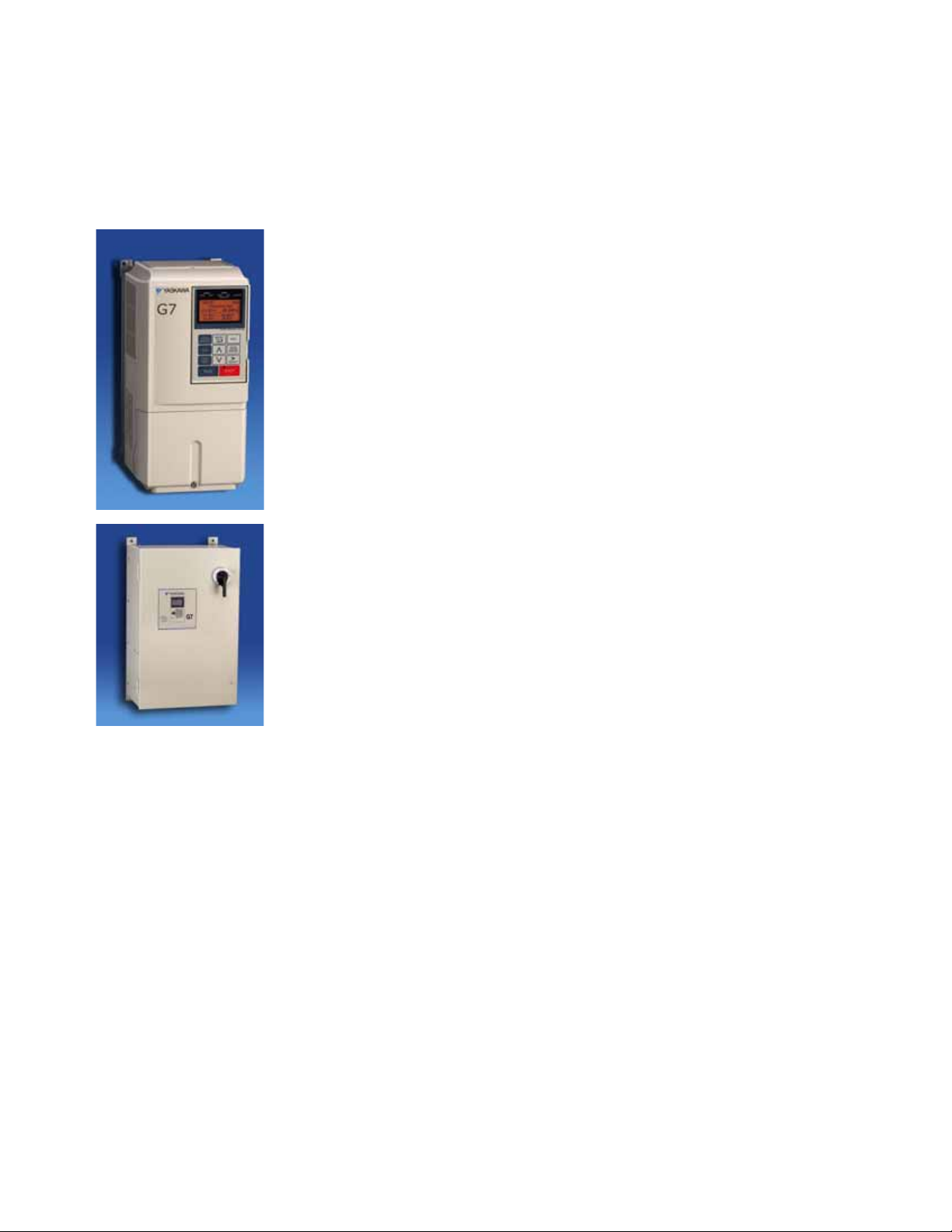
Table of Contents
G7 Drive (G7)
Description ................................................................... 3
Standard Drives ................................................................... 4
Dynamic Braking Options ................................................................... 6
Ring Kit Options ................................................................... 10
End Cap Kit Options ................................................................... 11
Reactor Options ................................................................... 12
Bus Reactor Options ................................................................... 14
Control Options ................................................................... 15
Communications Options ................................................................... 17
Dimensions and Data ................................................................... 18
Page
G7/Configured Package (G7C)
Description ................................................................... 19
Configured Drives and Options ................................................................... 24
Heatsink Filter Kit Options ................................................................... 26
Dimensions and Data ................................................................... 27
Software, Drawings, Manuals ................................................................... 28
Technical Training ................................................................... 29
Terms and Conditions ................................................................... 30
Options Matrix ................................................................... 32
Page 1
Data subject to change without notice
CA.G7.01, 6/1/08
Yaskawa Electric America
Page 3

This price book may describe trademarked equipment, which is the property of other companies. These
trademarks are the property of the registered owner companies and may include the following:
TM
DeviceNet
Profibus
Modbus
LonWorks
, trademark of ODVA.
®
, trademark of PROFIBUS International
®
, trademark of Schneider Automation, Inc.
®
, trademark of Echelon Corporation
Other Documents and Manuals are available to support special use or installation of this product. These
documents may be provided with the product or upon request. Contact Yaskawa Electric America, Inc. or visit
www.yaskawa.com, as required. Documents may include the following:
TM.G7.01... Drive Technical Manual included on CD ROM with product
TM.AFD.12... Profibus-DP... Manual included on CD ROM with product
TM.AFD.13... DeviceNet... Manual included on CD ROM with product
TM.AFD.14... DeviceNet... Manual included on CD ROM with product
TM.AFD.17... Modbus Plus... Manual included on CD ROM with product
TM.AFD.20... LonWorks... Manual included on CD ROM with product
TM.AFD.26... EtherNet/IP... Included on CD ROM with product
DriveWizard... Software and Manual...Included on CD ROM with product
Option Installation Guides... Included on CD ROM with product
REVISIONS
Change Page
Changed revision date all pages
CA.G7.01, 6/1/08
Data subject to change without notice
Yaskawa Electric America
Page 2
Page 4

Description
1/2 - 500HP
This amazing AC drive is the ultimate performance solution with increased speed and torque response to
provide servo-like performance from an induction motor. In addition, the G7 has the world’s first 480V 3-level
inverter architecture that eliminates or minimizes the installation problems associated with IGBT switching
and protects the entire motor-drive system.
Several control modes are provided. In open loop vector mode, the latest flux observer algorithms extend
speed range and provide maximum starting torque. In closed loop vector mode, 0.01% speed regulation and
1000:1 control range can be achieved. Zero-servo capability provides position control at zero speed. The G7
power section includes built-in bus choke (most ratings), 12-pulse input capability (most ratings), common
DC bus capability and regeneration options.
This G7 (480V) allows motor operation at very long cable lengths, with peak voltage being 30% less than
conventional drives. Motor bearing current is 50% less than standard drives, providing four times the bearing
life. Audible motor noise is 20% less.
DriveWizard™, DriveWorksEZ™ and Network Communication are available.
G7
Performance Features
• Ratings: 1/2 to 150HP, 208 VAC
1/2 to 150HP, 240 VAC
3/4 to 500HP, 480 VAC
• Overload capacity: heavy duty,
150% for 1 min, 200% Peak
• Starting torque:
150% at 1Hz (V/f), at 0.5 Hz (open loop),
at 0.3 Hz (closed loop)
• Output frequency: 0.01 to 400Hz
• Speed control range:
40:1 (V/f), 200:1 (open loop),
1000:1 (closed loop)
• Speed regulation:
1% (V/f), 0.2% (open loop), 0.01% (closed
loop)
• Speed response: 60Hz
• Torque response: 300Hz
• Speed reference resolution: 0.01% with
digital reference, 0.1% with analog
reference, 0.01 Hz with network input
• Speed/Torque/Position Control
• Zero-servo mode
• Adjustable accel/decel: 0.01 to 6000
seconds
• S-Curve: adjustable 0.00 to 2.50 seconds,
for each corner
• Stall prevention
• Inertia and Power loss ride-thru
• Programmable auto restart after
momentary power loss
Protective Features
• DC bus CHARGE indicator
• Optically-Isolated controls
• Phase-to-phase / phase-to-neutral short
circuit protection
• Ground fault protection
• Electronic motor overload (UL508C)
• Current and torque limit (four quadrant)
• Over-torque / under-torque detection
• Over-current, over-voltage, and overtemperature
• Motor thermistor input
• Input/output phase loss
Design Features
• LCD keypad display: 5 lines x 16 characters, backlit, 7 languages, copy function
• Simplified programming: Quick Start and
modified parameter groups
• Microprocessor logic: 32 bit
• Memory type: Flash memory for easy
upgrades, custom software applications,
and non-volatile program retention
• Control logic: 24VDC (sinking or sourcing)
• Terminal strip: Quick disconnect
• Front cover: Split for easy wiring
• Heat sink fan: Plug-in with on/off control
• Motor auto-tuning: Static and rotational
• Speed search: Bi-directional into rotating
motor
• Process control: PID, reference with PID trim
• Motor parameters: 2 sets
• Stopping methods: Ramp stop, coast stop,
fast stop, or high slip braking
• DC injection braking: Adjustable level, time
• Speed reference presets: 17 available
• Timer function: Programmable on/off delay
• Digital M.O.P.: Up/down/hold/reset reference
• Bias and gain: All analog and pulse train I/O
• Common DC bus capability: All models
• Dynamic braking transistor: 20 HP and below
(240VAC), 25 HP and below (460VAC)
• Bus Reactor: 25 HP and above (240VAC),
30HP and above (460VAC)
• Twelve-pulse capability: 25 HP and above
(240VAC), 30HP and above (460VAC)
Service Conditions
• Enclosure: NEMA 1 or protected chassis
• Ambient service temperatures:
-10 to 40°C (104°F) NEMA1,
-10 to 45°C (113°F) protected chassis
• Input frequency: 50/60Hz ± 5%
• Input voltage: +10% / -15%, 3 phase, 240
or 480VAC, phase insensitive
• Humidity: non-condensing 95% max
• Altitude: to 3300 feet (1000 meters) w/o
derate
• Vibration: 1G or less (10 to 20Hz), 0.6G or
less (20 to 55Hz)
Inputs and Outputs
• Analog inputs: 3 (2 programmable),
±10VDC (20K ohms) or 4 to 20 mA
(250 ohm), 11 bit plus sign
• Analog outputs: 2 programmable,
±10VDC or 4- to 20mA, 9 bit plus sign
• Digital inputs: 12 (10 programmable),
sinking or sourcing
• Digital outputs: 5 programmable, 3 form A
and two open collector
• Pulse train input: 1 programmable, 32 KHz
max
• Pulse train output: 1 programmable,
32 KHz max
• Fault contacts: 1 form C
• RS-232/422/485: Modbus RTU
Standards & Reliability
• UL, cUL & CE
• MBTF: Exceeds 28 years
Options
• DriveWorksEZ™ programming tool
• DriveWizard™ software (upload / download)
• Custom drive software
• Ethernet, DeviceNet, Profibus-DP, and
others
• Remote display/keypad
• High resolution I/O cards
• 120 VAC interface
• NEMA 12 enclosures
• Input breaker, disconnect, fuses
• Input/output reactors
• EMC-compliant filters
• Dynamic braking transistor (if not standard)
• Bus Reactor (if not standard)
• Line regeneration (RC5 or DC5)
480V Three-Level Inverter Benefits
• Lead length; Meets NEMA MG1 Part 31
• Motor bearing life: 4 times increase
• Quiet operation: 5-10dB of noise reduction
• Common mode current: 50% reduction
Page 3
Data subject to change without notice
CA.G7.01, 6/1/08
Yaskawa Electric America
Page 5
G7
Rated Input
Voltage
Drive Model Number
CIMR-G7U
Rated Output
Current (Amps)
Nominal HP
(2)
Standard Enclosure
Drive List
Price $
20P41 3.2 1/2
20P71 61
21P51 82
22P21 12 3
23P71 18 5
25P51 27 7.5
27P51 34 10
20111 49 15
20151 66 20
20181 80 25
20221 96 30
20300 130 40
20370 160 50
20450 183 60
20550 224 75
20750 300 100
20900 358 125
21100 415 150
20P41 3.2 3/4
20P71 61
21P51 82
22P21 12 3
23P71 18 5
25P51 27 7.5
27P51 34 10
20111 49 15
20151 66 20 NEMA 1
25
30
20221 96
(3)
NEMA 1
40
50
20370 160 60
20450 183
(3)
20550 224 75
20750 300 100
20900 358 125
21100 415 150
Protected Chassis
NEMA 1
Protected Chassis
Protected Chassis
Protected Chassis
NEMA 1
NEMA 1
NEMA 1
NEMA 1
80
130
NEMA 1
NEMA 1
NEMA 1
NEMA 1
NEMA 1
Protected Chassis
Protected Chassis
Protected Chassis
208V
240V
230V
20181
20300
Standard Drives
(1)
input, NEMA 1 or protected chassis enclosure
30
60
Page 4
G7 Drives - 1/2-500HP, 208-230/240 and 480V, 3-phase
(1) For single-phase input applications, consult Yaskawa Drives Applications Engineering for proper sizing
(2) Horsepower rating is based on standard NEMA B 4-pole motor design as represented in NEC table 430.150 Full-Load Current,
Three-Phase Alternating Current Motors
(3) Check motor FLA for proper drive sizing
CA.G7.01, 6/1/08
Data subject to change without notice
Yaskawa Electric America
Page 6

G7 Drives (Continued)
Rated Input
Voltage
Drive Model Number
CIMR-G7U
Rated Output
Current (Amps)
Nominal HP
(2)
Standard Enclosure
Drive List
Price $
40P41 1.8
3/4
NEMA 1
1
2
41P51 4.8 3
42P21 6.2
3
43P71 9 5
44P01 11 7.5
45P51 15
10
47P51 21 15
40111 27
20
40151 34
25
40181 42
30
40221 52 40
40301 65
50
40371 80 60
40451 97 75
40550 128 100
40750 165 125
40900 195 150
41100 240 200
41320 270
200
41600 302 250
41850 370 300
42200 450
350
400
500
NEMA 1
NEMA 1
NEMA 1
NEMA 1
NEMA 1
Protected Chassis
Protected Chassis
Protected Chassis
Protected Chassis
Protected Chassis
480V
40P71
43000
3.4
605
NEMA 1
NEMA 1
Standard Drives
G7
(3)
(1) For single-phase input applications, consult Yaskawa Drives Applications Engineering for proper sizing
(2) Horsepower rating is based on standard NEMA B 4-pole motor design as represented in NEC table 430.150 Full-Load Current,
(3) Check motor FLA for proper drive sizing
Three-Phase Alternating Current Motors
Page 5
(3)
CA.G7.01, 6/1/08
Data subject to change without notice
Yaskawa Electric America
Page 7

Dynamic Braking Options
Part
Number
CDBR-
Qty
List
Price
(ea.) $
Part
Number
URS000
Qty
List
Price $
Config-
uration
(2)
20P41 1/2 034 1
Single
(3)
3/4
1
21P51 2 023 1
Single
(3)
22P21 3 024 1
Single
(3)
23P71 5 025 1
Single
(3)
25P51 7.5 026 1
Single
(3)
27P51 10 027 1
Single
(3)
20111 15 140 1
Single
(4)
20151 20 136 1
Single
(4)
20181 25 135 1 Dual
20221 30 135 1 Dual
20300 40 129 1 Dual
20370 50
20450 60
20550 75 2110B 1 096 1 Single
Single
Single
1 Single
2 Dual
21100 150 2110B 2 097 1 Dual
1 each
Single
1 each
100
096 & 128
096 & 127
1
2110B
1
2110B &
2022B
1 each
2110B &
2022B
2022B 2
Included
Included
Included
Included
Rated
Input
Voltage
Drive Model
Number
CIMR-G7U
Nominal
HP
(1)
208V
20P71
20750
20900
100
125
Single
(3)
Resistor(s)
Total
List
Price $
(5)
1
Transistor Module(s)
Included
Included
022
G7
Dynamic Braking, 10% Duty Cycle - Used to assist the drive to periodically decelerate a load without overvoltage
trips. Ten percent dynamic braking is not typically used for "hold-back" type applications, such as unwinders, elevators, hoists,
or downhill conveyors. Dynamic braking consists of at least one transistor and at least one resistor, and are sized for rated
motor horsepower. The braking transistor may be included in the standard drive; this is indicated in the tables below. The
resistors are sized for a 10% duty cycle (10 seconds maximum on-time of every 100 seconds), and will provide approximately
150% braking torque. Refer to the dynamic braking instruction sheet for more details; consult Yaskawa for information on
higher duty cycles.
10% Duty
(1) Horsepower rating is based on standard NEMA B 4-pole motor design as represented in NEC table 430.150 Full-Load Current,
Three-Phase Alternating Current Motors
(2) Single = 1 resistor per package
Dual = 2 resistors per package (requires 2 DB transistor modules, as indicated in table above)
Triple = 3 resistors per package (requires 3 DB transistor modules, as indicated in table above)
(3) This resistor package provides 120% braking torque
(4) This resistor package provides 100% braking torque
(5) Total List Price includes all resistors and transistor modules to provide the Dynamic Braking function
CA.G7.01, 6/1/08
Data subject to change without notice
Yaskawa Electric America
Page 6
Page 8

Dynamic Braking Options
Part
Number
CDBR-
Qty
List
Price
(ea.) $
Part
Number
URS000
Qty
List
Price $
Config-
uration
(2)
1/2 034 1
Single
(3)
3/4 022 1
Single
(3)
20P71 1 022 1
Single
(3)
21P51 2 023 1
Single
(3)
22P21 3 024 1
Single
(3)
23P71 5 025 1
Single
(3)
25P51 7.5 026 1
Single
(3)
27P51 10 027 1
Single
(3)
20111 15 140 1
Single
(4)
20151 20 136 1
Single
(4)
25
30
20221 30 2022B 2 135 2 Dual
20300 50
20370 60
20450 60 100 1 Single
20550 75 096 1 Single
Single
Single
1 Single
2 Dual
21100 150 2110B 2 097 1 Dual
Resistor(s)
Total
List
Price $
(5)
Transistor Module(s)
Rated
Input
Voltage
Drive Model
Number
CIMR-G7U
Nominal
HP
(1)
Included
Included
20900
100
125
Included
Included
Included
2110B
230/
240V
2022B
2
20P41
20181
20750
2110B &
2022B
2110B &
2022B
1
1
1 each
2110B
135
100
096 & 128
096 & 127
2
1
1 each
1 each
Dual
Single
Dynamic Braking, 10% Duty Cycle (continued for 230/240V)
10% Duty
G7
(1) Horsepower rating is based on standard NEMA B 4-pole motor design as represented in NEC table 430.150 Full-Load Current,
Three-Phase Alternating Current Motors
(2) Single = 1 resistor per package
Dual = 2 resistors per package (requires 2 DB transistor modules, as indicated in table above)
Triple = 3 resistors per package (requires 3 DB transistor modules, as indicated in table above)
(3) This resistor package provides 120% braking torque
(4) This resistor package provides 100% braking torque
(5) Total List Price includes all resistors and transistor modules to provide the Dynamic Braking function
Page 7
Data subject to change without notice
Yaskawa Electric America
CA.G7.01, 6/1/08
Page 9
Dynamic Braking Options
Part
Number
CDBR-
Qty
List
Price
(ea.) $
Part
Number
URS000
Qty
List
Price $
Configuration
(2)
40P41 3/4 32 1
Single
(3)
1
2
41P51 3
42P21 3
43P71 5 35 1
Single
(3)
44P01 7.5 36 1
Single
(3)
45P51 10 37 1
Single
(3)
47P51 15 38 1
Single
(3)
40111 20
40151 25
40181 30 150 1 Single
40221 40 142 1 Single
40301 50 151 1 Dual
40371 60 151 1 Dual
40451 75 143 1 Dual
40550 100
40750 125
40900 150 4220B 1 165 1 Single
Single
Single
Single
Single
1 Single
2 Dual
41850 300
42200 350
Dual
Single
450
500
1
Resistor(s)
Total
List
Price $
(5)
Transistor Module(s)
Included
Included
33
Rated
Input
Voltage
Drive Model
Number
CIMR-G7U
Nominal
HP
(1)
40P71
480V
41100 200
41320 200
41600
Included
Included
Included
Included
4045B 2
1
4220B &
4045B
1
4045B
1
400
4220B
4220B &
4045B
4220B &
4045B
4220B
43000
1
250
4220B
4220B
2
3
3
120 & 165
167
34
40
165 & 142
119
165 & 142
165 & 143
166
1
1
1
1
1
1
1 each
1 each
1 each
Single
(3)
Single
(3)
Single
(3)
Single
Dual
Triple
G7
Dynamic Braking, 10% Duty Cycle (continued for 480V)
10% Duty
(1) Horsepower rating is based on standard NEMA B 4-pole motor design as represented in NEC table 430.150 Full-Load Current,
Three-Phase Alternating Current Motors
(2) Single = 1 resistor per package
Dual = 2 resistors per package (requires 2 DB transistor modules, as indicated in table above)
Triple = 3 resistors per package (requires 3 DB transistor modules, as indicated in table above)
(3) This resistor package provides 120% braking torque
(4) This resistor package provides 100% braking torque
(5) Total List Price includes all resistors and transistor modules to provide the Dynamic Braking function
CA.G7.01, 6/1/08
Data subject to change without notice
Yaskawa Electric America
Page 8
Page 10
Dynamic Braking Options
Part Number Qty List Price $ Braking Torque %
20P41 1/2 R7505 220
20P71 1 R7505
125
21P51 2 R7504
125
22P21 3 R7503
120
23P71 5 R7510
1 100
20P41 1/2 R7505 220
20P41 3/4 R7505 220
20P71 1 R7505
125
21P51 2 R7504
125
22P21 3 R7503
120
23P71 5 R7510
100
40P41
3/4
R7508 1 230
40P71
1
R7508 130
40P71
2
R7508 130
41P51 3 R7507
125
42P21 3 R7506
115
43P71 5 R7505
1 110
1
1
1
1
Resistor
208V
240V
480V
Rated Input
Voltage
Drive Model Number
CIMR-G7U
Nominal HP
(1)
1
1
1
3% Duty
Dynamic Braking, 3% Duty Cycle - Used to assist the drive to periodically decelerate a load without overvoltage
trips. Three percent dynamic braking is not applicable for "hold-back" type applications, such as unwinders, elevators, hoists,
or downhill conveyors. Dynamic braking consists of at least one transistor and at least one resistor, and are sized for rated
motor horsepower. The braking transistor is included in the standard drive for these resistors. The resistors are sized for a 3%
duty cycle (3 seconds maximum on-time of every 100 seconds), and will provide at least 100% braking torque. Refer to the
dynamic braking instruction sheet for more details; consult Yaskawa for information on higher duty cycles. These resistors
can be mounted directly to the heatsink on the back of the drive.
G7
(1) Horsepower rating is based on standard NEMA B 4-pole motor design as represented in NEC table 430.150 Full-Load Current,
Three-Phase Alternating Current Motors
Page 9
Data subject to change without notice
Yaskawa Electric America
CA.G7.01, 6/1/08
Page 11
Ring Kit Options
Rated Input Voltage
Drive Model Number
CIMR-G7U
Kit Model No.
UDA00417-
Kit List Price $
20P41 thru 23P71 D
25P51
27P51
20111
20151
20181 F
20221 E
20300 thru 21100
40P41 thru 44P01 D
45P51
47P51
40111
40151
40181
40221
40301 thru 40451 A
40550 thru 43000
208-230/240V
Not Available
480V
Not Available
C
B
C
B
E
G7
Ring Kit - These kits allow installation of the drive into a customer's enclosure with the heatsink mounted out the back to
reduce overall enclosure size. Each kit includes all of the necessary components, including hardware, gaskets and
instructions.
CA.G7.01, 6/1/08
Data subject to change without notice
Yaskawa Electric America
Page 10
Page 12

End Cap Kit Options
Height (in.) Width (in.) Depth (in.)
20P41 thru 20221
20300
20370
20450
20550
20750 F 48.94 19.84 No Change
20900
21100
40P41 thru 40451
40550
40750
40900
41100
41320
41600
41850
42200
43000
48.94
52.13
17.83
19.84
22.80
40.43
Kit List
Price $
480V
Not Required
Not Available
Not Required
Not Available
No Change
No Change
No Change
No Change
Overall Drive Dimensions
Rated Input
Voltage
Drive Model
Number
CIMR-G7U
Kit Model No.
UDA00365-
208-230/240V
No Change
31.85
40.43
14.96
17.83
C
E
E
F
P
G7
End Cap Kit, NEMA 1 - This option consists of a top and bottom cover to convert a protected chassis drive to a NEMA
1 enclosed unit. This option DOES NOT provide additional space for mounting auxilliary components (i.e. circuit breaker, input
fuses, reactor, etc.).
Page 11
CA.G7.01, 6/1/08
Data subject to change without notice
Yaskawa Electric America
Page 13

HLW HLW
20P41 3.2 0020 0021
20P71 6
0027
0028
21P51 8
0032
0033
22P21 12
0036
0032
23P71 18
0041
0036
8.0 8.0 6.0
25P51 27
0046 0047 13.0 13.0 13.0
27P51 34 0050 0048
20111 49
0054
0055
20151 66
0058
0059
20181 80
0172
0062
20221 96
0066
0067
20300 130
0066
0067
20370 160
0072
0073
20450 183
0077
0078
20550 224
0082 13.0 13.0 13.0
0083
20750 300
0087
24.0 17.0 17.0 0088
20900 358
0173 0092
21100 415
0174 0096
20P41 3.2 0020 0021
20P71 6
0027
0028
21P51 8
0027
0028
22P21 12
0036
0037
23P71 18
0036 8.0 8.0 6.0
0037
8.0 8.0 6.0
25P51 27
0046 13.0 13.0 13.0
0047
13.0 13.0 13.0
27P51 34
0050
0051
20111 49
0054
0055
20151 66
0058
0059
20181 80 0172 0062
20221 96
0172 0062
20300 130 0066 0067
20370 160 0072 0073
20450 183 0077 0078
20550 224
0082 13.0 13.0 13.0 0083
20750 300 0087 24.0 17.0 17.0
0088
20900
358 0173 0092
21100 415 0174 0096
24.0 17.0 17.0
24.0 17.0 17.0
13.0
13.0 13.0 13.0
13.0
13.0
13.0 13.0 13.0
6.0
8.0 8.0 6.0
8.0
13.0
24.0 17.0 17.0
13.0
13.0 13.0 13.0
6.0
8.0 8.0 6.0
24.0 17.0 17.0
8.0
13.0
13.0
13.0
8.0
13.0
13.013.0 13.0 13.0
13.0 13.0 13.0
13.0 13.0
13.0 13.0 13.0
13.0
13.0 13.0
17.0 17.0
13.0
13.0 13.0
13.0 13.0 13.0
8.0 6.0
8.0 8.0 6.0
8.0
Dimensions (in)
208V
230/
240V
8.0 8.0 6.0
8.0 8.0 6.0
13.0
24.0 17.0
8.0
13.0
13.0
13.013.0
13.0
13.0
17.0
13.0
24.0
13.0 13.0
13.0 13.0
Rated
Input
Voltage
Drive Model
Number
CIMR-G7U
Rated
Output
Current
(Amps)
5% Enclosed Reactor3% Enclosed Reactor
Part
Number
05P00620-
List
Price $
Part
Number
05P00620-
List
Price $
Dimensions (in)
Reactor Options
G7
Reactor, 3% and 5% Impedance - May be used on either the input or output of a drive to reduce the effect of load or
line side transients on the drive. The three-phase reactors are provided in a separate NEMA 1 enclosure.
CA.G7.01, 6/1/08
Data subject to change without notice
Yaskawa Electric America
Page 12
Page 14

Reactor, 3% and 5% Impedance (continued for 480V)
HLW HLW
40P41 1.8 0015 0016
40P71 3.4 0021 0022
41P51 4.8 0029 0030
42P21 6.2 0028 0030
43P71 9 0028 0029
44P01 11 0033 0034
45P51 15 0037 8.0 8.0 6.0
0038
47P51 21 0042 13.0 13.0 13.0 0043
40111 27 0047 0048
40151 34 0051
0048
40181 42 0055
0056
40221 52 0055
0056
40301 65 0059
0060
40371 80 0062 0063
40451 97 0062 0063
40550 128 0067
0068
40750 165 0073
0074
40900 195 0078
0079
41100 240 0083 0084
41320 270 0088 0089
41600 302
0088 0089
41850 370 0092
0093
42200 450 0096
0097
43000 605 0100
0101
17.0 17.024.0 17.0 17.0 24.0
13.0
13.0
480V
13.0 13.0 13.0
8.0 8.0 6.0
24.0
Rated
Input
Voltage
Drive Model
Number
CIMR-G7U
Rated
Output
Current
(Amps)
5% Enclosed Reactor3% Enclosed Reactor
Part
Number
05P00620-
List
Price $
Part
Number
05P00620-
List
Price $
Dimensions (in)
13.0
13.0
8.0
13.0
13.0 13.0
8.0
13.0
13.0
13.
0
13.0
13.0
8.0 8.0
Dimensions (in)
8.0 8.0 6.0 8.0 6.0
8.0 8.0 6.0
17.0
8.0 6.0
13.0 13.0
13.0 13.0
24.0 17.0 17.0
17.0
13.0
13.0 13.0
13.0 13.0
6.0
13.0
13.0 13.0 13.0
13.0
13.0
13.0 13.0 13.0
17.0 17.0
24.0 17.0 17.0
24.0
Reactor Options
G7
Page 13
Data subject to change without notice
CA.G7.01, 6/1/08
Yaskawa Electric America
Page 15

Bus Reactor Options
HLW HLW
20P41 3.2 URX000040 2.50 2.88 1.50 URX000041 3.25 3.75 2.00
20P71 6 TBD 3.25 3.75 2.00 05P00620-0111 4.50 3.81 2.82
21P51 8 URX000045 4.50 3.81 2.82 05P00652-0213 4.50 3.81 2.82
22P21 12 TBD 4.50 3.81 2.82 URX000048 4.50 3.81 3.75
23P71 18 URX000051 4.50 3.81 2.82 URX000053 4.50 3.81 3.00
25P51 27 05P00620-0120 4.31 3.81 3.32 URX000055 5.25 4.63 4.25
27P51 34 05P00620-0123 4.50 3.81 3.13 URX000057 5.25 4.63 4.00
20111 49 URX000063 4.00 4.63 5.00 URX000065 5.50 6.50 6.25
20151 66 05P00620-0129 4.00 4.63 6.00 URX000069 4.00 4.63 7.00
20181 thru
21100
80 thru 415
20P41 3.2 05P00620-0111 4.50 3.81 2.82 URX000044 5.25 4.63 4.00
20P71 6 TBD 3.25 3.75 2.00 05P00620-0111 4.50 3.81 2.82
21P51 8 TBD 3.25 3.75 2.00 URX000046 5.25 4.63 3.50
22P21 12 TBD 4.50 3.81 2.82 URX000048 4.50 3.81 3.75
23P71 18 URX000052 4.50 3.81 3.75 URX000053 4.50 3.81 3.00
25P51 27 05P00620-0120 4.31 3.81 3.32 URX000055 5.25 4.63 4.25
27P51 34 05P00620-0124 4.50 3.81 3.75 URX000057 5.25 4.63 4.00
20111 49 URX000063 4.00 4.63 5.00 URX000065 5.50 6.50 6.25
20151 66 05P00620-0129 4.00 4.63 6.00 URX000069 4.00 4.63 7.00
20181 thru
21100
80 thru 415
40P41 1.8 URX000042 4.50 3.81 2.82 URX000039
3.25 3.75 2.00
40P
71 3.4 URX000041 3.25 3.75 2.00 URX000042 4.50 3.81 2.82
41P51 4.8
42P21 6.2
43P71 9 URX000046 5.25 4.63 3.50 URX000044 5.25 4.63 4.00
44P01 11 05P00652-0216 5.25 4.63 4.00 URX000049 5.25 4.63 5.25
45P51 15 URX000048 4.50 3.81 3.75 URX000049 5.25 4.63 5.25
47P51 21 URX000053 4.50 3.81 3.00 URX000054 5.25 4.63 5.25
40111 27 URX000055 5.25 4.63 4.25 URX000056 5.25 4.63 5.25
40151 34 URX000057 5.25 4.63 4.00 URX000058 6.55 6.50 6.00
40181 thru
43000
42 thru 605
Built-in;
additional DC bus reactor not required
05P00620-0111
4.50 3.81 2.82
URX000044
5.25 4.63
208V
230/
240V
480V
Built-in;
additional DC bus reactor not required
Built-in;
additional DC bus reactor not required
Built-in;
additional DC bus reactor not required
Built-in;
additional DC bus reactor not required
4.00
Dimensions (in)
Built-in;
additional DC bus reactor not required
Rated
Input
Voltage
Number
CIMR-G7U
Rated
Output
Current
(Amps)
5% DC Bus Reactor3% DC Bus Reactor
Part Number
List
Price $
Part Number
List
Price $
Dimensions (in)
G7
DC Bus Reactor - May be used on the DC bus of a drive to reduce the effect of line side transients on the drive. The DC
bus reactors are available loose in an open configuration, and must be mounted in a NEMA 1 enclosure.
Drive Model
CA.G7.01, 6/1/08
Data subject to change without notice
Yaskawa Electric America
Page 14
Page 16

Control Options
G7
Control Options - These cards, cables and devices add control functionality to the standard drive. Items are
shipped loose, unmounted. See Configured Section for factory mounted and wired control.
Analog Input Options
Analog Input (14 Bit). This option provides for the
interface of 2 high resolution analog inputs to
the drive.
Signal levels (fixed):
1 channel, 0 to 10VDC (20kOhm)
1 channel, 4 to 20mADC (250Ohm)
Mounts at option connector 2CN
Model No. AI-14U........................................ List $
Analog Input (13 Bit + Sign). This option provides for the interface
of 3 high resolution analog inputs to the drive.
Signal levels (individually selectable):
0 to ±10VDC (20kOhm),
4 to 20mADC (250Ohm)
Mounts at option connector 2CN
Model No. AI-14B........................................ List $
Analog Input, Isolated (13 Bit + Sign or 14 Bit). This option
provides for the interface of 3 isolated, high resolution analog inputs
to the drive.
Signal levels (individually selectable):
0 to ±10VDC (20kOhm), 13 Bit + Sign,
0/4 to 20mADC (250Ohm), 14 Bit
Mounts at option connector 2CN
Model No. AI-040.........................................List $
Analog Output Options
Analog Output (8 Bit). This option provides 2 signals for remote
metering of any two of the drive’s “U1” monitors. These are in
addition to the two standard analog outputs.
Signal levels (fixed):
0 to 10VDC (20kOhm)
Mounts at option connector 3CN
Model No. AO-08......................................... List $
Analog Output (11 Bit + Sign). This option provides 2 signals for
remote metering of any two of the drive’s “U1” monitors. These are
in addition to the two standard analog outputs.
Signal levels (individually selectable):
0 to ±10VDC (20kOhm)
Mounts at option connector 3CN
Model No. AO-12......................................... List $
Analog Output, Isolated (11 Bit + Sign). This option provides 2
isolated signals for remote metering of any two of the drive’s “U1”
parameters. These are in addition to the two standard analog
outputs.
Signal levels (individually selectable):
0 to ±10VDC (20kOhm),
0 to 20mADC (500Ohm max),
4 to 20mADC (500Ohm max)
Mounts at option connector 3CN
Model No. AO-001 (formerly AO-12B2) List $
Trim Potentiometer. This option provides a 5kOhm potentiometer
for use as a dropping resistor for maximum or minimum analog
input trim.
Mounts to control terminal strip
Model No. AI-001.........................................List $
3-15PSI Transducer. This option provides for the interface of a 3 to
15PSI pneumatic signal, and provides a 4 to 20mA output signal
proportional to the input signal to the drive.
Mounts to control terminal strip
Model No. AI-010.........................................List $
Digital Input Options
Digital Input (8 Bit). This option provides for the interface of an 8
bit digital input (binary or BCD) to the drive.
Mounts at option connector 2CN
Model No. DI-08............................................ List $
Digital Input (12 or 16 Bit). This option provides for the interface of
a 12 or 16 bit digital input (binary or BCD) to the drive.
Mounts at option connector 2CN
Model No. DI-16H2 .................................... List $
120VAC Logic Interface (8-Input). This option provides for the
interface of 120VAC control logic circuits to the drive. This option is
used for digital inputs S1 to S8.
Mounts to control terminal strip
Model No. DI-001.........................................List $
120VAC Logic Interface (4-Input). This option provides for the
interface of 120VAC control logic circuits to the drive. This option is
used for digital inputs S9 to S12.
Mounts to control terminal strip
Model No. DI-003........................................ List $
Page 15
Data subject to change without notice
Yaskawa Electric America
CA.G7.01, 6/1/08
Page 17

Control Options
G7
Control Options (continued)
Digital Output Options
Digital Output (2 Channel). This option provides 2 additional
digital outputs for use in monitoring the status outputs of the drive.
Signal levels:
2 channels, Form C, 250VAC, 30VDC, 1A
Mounts at option connector 3CN
Model No. DO-02C.................................... List $
Digital Output (8 Channel). This option provides 8 additional
digital outputs for use in monitoring the status outputs of the drive.
Signal levels:
2 channels, Form A, 250VAC, 30VDC, 1A
6 channels, PHC, 48VDC, 50mA, Shared Common
Mounts at option connector 3CN
Model No. DO-08 ......................................... List $
Encoder Feedback Options
Single Encoder (PG) Feedback - Line Driver. This option
provides velocity and direction feedback from an encoder. This is
primarily used for motor speed feedback in closed loop flux vector
control. A 5VDC buffered output is also included.
Signal levels:
5 or 12VDC differential line driver with compliments
Maximum input frequency: 300kHz
Phases A and B (Z required with some custom software)
Mounts at option connector 4CN
Model No. PG-X2 ........................................ List $
Single Encoder (PG) Feedback - Open Collector. This option
provides velocity and direction feedback from an encoder. This is
primarily used for motor speed feedback in closed loop flux vector
control. A 24DC buffered output (open collector) is also included.
Signal levels:
12VDC differential open collector with compliments
Maximum input frequency: 32kHz
Phases A and B (No marker pulse capability)
Mounts at option connector 4CN
Model No. PG-B2 ........................................ List $
Digital Operator Options
Digital Operator (LCD). This option is the standard digital operator
found on the drive. This option is only needed if the original keypad
is lost or damaged.
Features include:
LCD keypad display, 5 lines x 16 characters, backlit
7 languages
Copy function
Mounts to keypad port
Model No. 300-016-999 ..........................List $
UL Rated Remote Operator Kits. This option is used to extend
the existing Digital Operator to the wall of a separately priced,
oversized UL Type 1, 3R, 4, 4X, or 12 enclosure (IPX6
environment). Price includes a faceplate bezel with digital operator
carrier and membrane to cover the operator cutout in the enclosure
door, a 3-foot cable, a 10-foot cable, and a 1:1 template for cutting
the necessary cutouts in the enclosure. Keypad can be removed
after kit installation.
Mounts to keypad port and enclosure wall.
Model No. UUX000458 (Blank Membrane) .........................List $
Model No. UUX000459 (Yaskawa Logo Membrane) .......... List $
Remote Operator Kit. This option is used to extend the existing
Digital Operator to the wall of a separately priced, oversized NEMA
1 enclosure (No UL rating). Price includes a faceplate membrane to
cover the operator cutout in the enclosure door, a 3-foot cable, a 10foot cable, a remote digital operator carrier, and a 1:1 template for
cutting the necessary cutouts in the enclosure.
Note: Keypad cannot be removed after initial installation.
Mounts to keypad port and enclosure wall.
Model No. UUX000444 (Yaskawa Logo Membrane) .......... List $
Dual Encoder (PG) Feedback - Line Driver. This option provides
velocity and direction feedback from 2 encoders. This card is used
for 2-motor operation with standard software and for some custom
software titles. A 5VDC buffered output is also included.
Signal levels:
5 or 12VDC differential line driver with compliments
Maximum input frequency: 300kHz
Phases A and B (Z required with some custom software)
Mounts at option connector 4CN
Model No. PG-W2 ...................................... List $
CA.G7.01, 6/1/08
Data subject to change without notice
Yaskawa Electric America
Page 16
Page 18

Communications Options
G7
Communications Options - These communications options are provided loose, unmounted. Network
communications are available for most popular protocols.
DeviceNet™ With ADR. Each DeviceNet network supports up to
63 drives. Controllers are available from many PLC and/or PC
suppliers. The DeviceNet network communications option board is
designed to comply with all pertinent aspects of the ODVA (Open
DeviceNet Vendor Association) specification and AC drive profile.
All parameters, diagnostics, and operational commands are
accessible via DeviceNet. Automatic Device Replacement (ADR) is
supported in this DeviceNet option, including the functions of Auto
Baud Rate sensing and Faulted Node Recovery (using Group 4
messaging). The DeviceNet satellite board mounts integrally in the
drive and provides a DeviceNet standard open tap connector.
Electronic Data Sheets may be downloaded from
www.yaskawa.com to assist with network configuration and drive
setup.
Mounts at option connector 2CN.
Model No. CM012 ............................................List $
Other DeviceNet Options. For DeviceNet option kits CM056 and
CM059, please follow the guidelines listed below. Please download
the application note AN.AFD.14 from www.yaskawa.com, which
details the exact differences between all the DeviceNet option kits.
New Installations
New installations without any requirements of backwards
compatibility should use CM012 kit. The CM012 incorporates all the
functionality of the CM056 and CM059 as well as ADR and many
other new features.
Existing Installations
When replacing a failed card in the field or adding an additional
drive to an existing network, it is generally recommended to use the
existing kit (CM056 or CM059) found in the installation. This will
ease in the support of the network.
Note: Each DeviceNet kit has unique EDS (electronic data sheets)
files for each model of every drive series. These can be found on
www.yaskawa.com. If you choose to replace an existing kit with a
different kit, you must use the new EDS file as well.
Profibus DP. This option complies with the Profibus DP protocol
specification. All parameters, diagnostics and operational
commands are accessible via Profibus. The option board provides
convenient Phoenix-type teminations for landing the shielded,
twisted-pair wiring. Each Profibus network supports up to 99 drives.
This option supports all of the Profibus data rates from 9.6 Kbps to
12 Mbps. Up to 32 bytes of input data and 32 bytes of output data
are provided per message transaction. GSD files may be
downloaded from www.yaskawa.com to assist with network
configuration and drive setup.
Mounts at option connector 2CN.
Model No. CM061 ..................................List $
LonWorks. This option is compatible with the Lon Mark
Interoperability Association and complies with the Functional Profile
for a Variable Frequency Motor Drive. The option board features the
FFT-10A Free Topology Twisted-Pair Transceiver. Network
connectivity is facilitated by either a Phoenix-style screw termination
or RJ-45 connector. The kit includes a 12-inch pigtail (UWR00567-
1) for interface wiring of the phoenix terminal block. Optional longer
pigtail assemblies are available for use when drive is mounted
within another enclosure. The 20-inch cable is for wall mount
enclosures. The 78-inch cable may be used with any enclosure and
may be cut to any length required.
Mounts at option connector 2CN. Covers 3CN. Blocks 4CN.
Model No. CM048................................................................. List $
Model No. UWR00567-2 (20-inch cable)............................. List $
Model No. UWR00567-3 (78-inch cable)............................. List $
Modbus Plus. This option complies with Modicon's ModConnect
Partners program and provides a seamless interface to Quantum,
984 and Compact PLCs. All parameters, diagnostics and
operational commands are accessible via Modbus Plus. The option
board provides a 9-pin D-shell connector for easy wiring and
communicates via a 1 Mbps, twisted-pair, Local Area Network.
Each Modbus Plus network supports up to 63 drives.
Mounts at option connector 2CN. Covers 3CN.
Model No. CM071...................................... List $
Modbus TCP/IP. This option complies with the Modbus TCP/IP
protocol specification. This allows for communication over 10/100
Mbps Ethernet networks. This option has the ability to configure the
IP Address from a user specified IP address, from a DHCP host or
from a BootP host. All parameters, diagnostics and operational
commands are accessible via Modbus TCP/IP. Auto-tuning the
motor is also possible through this option using the DriveWizard PC
program. This option supports up to 10 simultaneous PLC/PC
connections.
Mounts at option connector 2CN.
Model No. CM090...................................... List $
EtherNet/IP. This option complies with the EtherNet/IP protocol
specification. This allows for communication over 10/100 Mbps
Ethernet networks. This option has the ability to configure the IP
Address from a user specified IP address, from a DHCP host or
from a BootP host. All parameters, diagnostics and operational
commands are accessible via EtherNet/IP. Auto-tuning the motor is
also possible through this option using the DriveWizard PC
program.
Mounts at option connector 2CN.
Model No. CM092...................................... List $
Page 17
Data subject to change without notice
CA.G7.01, 6/1/08
Yaskawa Electric America
Page 19

G7
H W D Heatsink Internal Total
20P41 3.2 3/4 21 36 57
20P71 6 1 43 42 85
21P51 8 2 58 47 105
22P21 12 3 83 53 136
23P71 18 5 122 64 186
25P51 27 7.5 13.2 187 87 274
27P51 34 10 15.4 263 112 375
20111 49 15 13.78 DD.G7.FR4A.N1.01 357 136 493
20151 66 20 14.96 DD.G7.FR4C.N1.01 473 174 647
20181 80 25 & 30 21.06 10.00 10.24 52.8 DD.G7.FR5.N1.01 599 241 840
20221 96 30 24.21 10.98 10.24 59 DD.G7.FR6A.N1.01 679 257 936
20300 130 40 & 50 11.81 125 DD.G7.FR7.IP00.01 878 362 1240
20370 160 60 12.99 139 DD.G7.FR8.IP00.01 1080 434 1514
20450 183 60 189 1291 510 1801
20550 224 75 191 1474 607 2081
2075 300 100 33.46 19.69 14.17 238 DD.G7.FR11.IP00.01 2009 823 2832
20900 358 125 1660 871 2531
21100 415 150 2389 1194 3583
40P41 1.8 3/4 10 39 49
40P71 3.4 1 & 2 21 44 65
41P51 4.8 3 33 46 79
42P21 6.2 3 41 49 90
43P71 9 5 77 63 140
44P01 11 7.5 100 66 166
45P51 15 10 132 80 212
47P51 21 15 197 107 304
40111 27 20 246 116 362
40151 34 25 311 135 446
40181 42 30 354 174 528
40221 52 40 516 210 726
40301 65 50 633 246 879
40371 80 60 737 285 1022
40451 97 75 28.15 12.95 11.22 88 DD.G7.FR9B.N1.01 929 340 1269
40550 128 100 198 1239 488 1727
40750 165 125 200 1554 597 2151
40900 195 150 240 1928 762 2690
41100 240 200 279 2299 928 3227
41320 270 200 363 2612 1105 3717
41600 302 250 385 3614 1501 5115
41850 370 300 579 4436 1995 6431
42200 450 350 616 5329 2205 7534
43000 605 400 & 500 58.07 36.06 16.34 906 DD.G7.FR15.IP00.01 6749 2941 9690
DD.G7.FR10.IP00.01
DD.G7.FR11.IP00.01
DD.G7.FR13.IP00.01
DD.G7.FR14.IP00.01
DD.G7.FR3A.N1.01
DD.G7.FR4B.N1.01
DD.G7.FR6B.N1.01
DD.G7.FR9A.N1.01
DD.G7.FR12.IP00.01
DD.G7.FR1.N1.01
DD.G7.FR2.N1.01
DD.G7.FR2.N1.01
DD.G7.FR1.N1.01
DD.G7.FR2.N1.01
DD.G7.FR3A.N1.01
DD.G7.FR10.IP00.01
NEMA 1
Protected
Chassis
NEMA 1
NEMA 1
Protected
Chassis
NEMA 1
36.06 22.64 14.96
51.38 27.95 16.34
28.54 17.72 13.78
33.46 19.69 14.17
25.00 12.95 11.22 86
21.06 10.98 10.24 64
13.78 9.45 8.27 22
11.81 7.87 7.87 15.4
Standard
Enclosure
Dimension
Drawing
Number
(3)
Heat Loss (watts)
(4)
208V/
240V/
230V
11.02 5.51
6.30
7.09
11.81 7.87
Weight
(lbs.)
(2)
7.87
6.6
8.8
Rated
Input
Voltage
Drive
Model
Number
CIMR-G7U
Rated
Output
Current
(Amps)
9.45
Nominal
HP
(1)
Physical
Dimensions (in.)
8.27 24.2
23.62 14.76
480V
28.54 17.72 13.78
34.84 22.64 14.96
11.02 5.51
6.30
330
7.09
7.7
9.9
Dimensions and Data
(1) Horsepower rating is based on standard NEMA B 4-pole motor design as represented in NEC table 430.150 Full-Load Current,
(2) This data represents the drive weight only, not shipping weight.
(3) Please refer to Yaskawa’s website at www.yaskawa.com for dimension drawings.
(4) Total Heat Loss is the amount of heat dissipated by the drive at full load. This data is separated into "Heatsink" and "Internal" values.
CA.G7.01, 6/1/08
Data subject to change without notice
Yaskawa Electric America
Three-Phase Alternating Current Motors
The value in the "Heatsink" column is the amount of heat dissipated by the heatsink, and would not need to be considered when
calculating the enclosure size for applications that may require mounting the heatsink out the back of the enclosure using the Ring Kit
option.
Page 18
Page 20
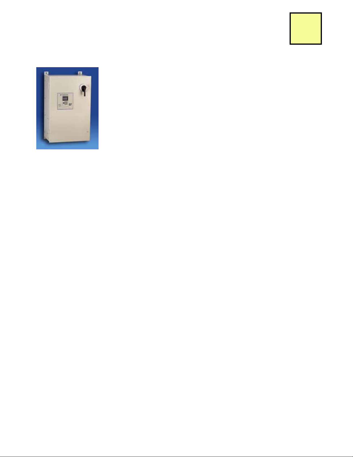
Description
3/4-500HP
G7/Configured
The G7/Configured package provides a G7 drive in a NEMA 12, UL Type 1, IP22 or 54 enclosure, with space
for several commonly used options, such as reactors, RFI filters, circuit breakers, etc. The G7/Configured
has been designed for flexibility in providing the features and options commonly demanded by industrial
control designers.
The G7 drive is the ultimate performance solution with increased speed and torque response to provide
servo-like performance from an induction motor in speed, torque, or position control applications. In addition,
the G7 has the world’s first 480V 3-level inverter architecture that eliminates or minimizes the installation
problems associated with IGBT switching and protects the entire motor-drive system. This patented design
can eliminate peripheral components typically required to solve installation problems. This G7 allows motor
operation at very long cable lengths, meeting NEMA MG1 Part 31, with peak voltage being 30% less than
conventional drives. With motor bearing current being typically 50% less than standard drives, the G7
provides four times the motor bearing life. Audible motor noise on the 480V G7 drive is 5-10dB (20%) less
than the prior generation drive, even when operating at half the carrier frequency. Common mode current is
half that of conventional drives.
G7C
Performance Features
• Ratings: 1/2 to 150HP, 208 VAC
1/2 to 150HP, 240 VAC
3/4 to 500HP, 480 VAC
• Overload capacity: heavy duty,
150% for 1 min, 200% Peak
• Starting torque:
150% at 1Hz (V/f), at 0.5 Hz (open loop),
at 0.3 Hz (closed loop)
• Output frequency: 0.01 to 400Hz
• Speed control range:
40:1 (V/f), 200:1 (open loop),
1000:1 (closed loop)
• Speed regulation:
1% (V/f), 0.2% (open loop), 0.01% (closed
loop)
• Speed response: 60Hz
• Torque response: 300Hz
• Speed reference resolution: 0.01% with
digital reference, 0.1% with analog
reference, 0.01 Hz with network input
• Speed/Torque/Position Control
• Zero-servo mode
• Adjustable accel/decel: 0.01 to 6000
seconds
• S-Curve: adjustable 0.00 to 2.50 seconds,
for each corner
• Stall prevention
• Inertia and Power loss ride-thru
• Programmable auto restart after
momentary power loss
Protective Features
• DC bus CHARGE indicator
• Optically-Isolated controls
• Phase-to-phase / phase-to-neutral short
circuit protection
• Ground fault protection
• Electronic motor overload (UL508C)
• Current and torque limit (four quadrant)
• Over-torque / under-torque detection
• Over-current, over-voltage, and overtemperature
• Motor thermistor input
• Input/output phase loss
Design Features
• LCD keypad display: 5 lines x 16 characters, backlit, 7 languages, copy function
• Simplified programming: Quick Start and
modified parameter groups
• Microprocessor logic: 32 bit
• Memory type: Flash memory for easy
upgrades, custom software applications,
and non-volatile program retention
• Control logic: 24VDC (sinking or sourcing)
• Terminal strip: Quick disconnect
• Front cover: Split for easy wiring
• Heat sink fan: Plug-in with on/off control
• Motor auto-tuning: Static and rotational
• Speed search: Bi-directional into rotating
motor
• Process control: PID, reference with PID trim
• Motor parameters: 2 sets
• Stopping methods: Ramp stop, coast stop,
fast stop, or high slip braking
• DC injection braking: Adjustable level, time
• Speed reference presets: 17 available
• Timer function: Programmable on/off delay
• Digital M.O.P.: Up/down/hold/reset reference
• Bias and gain: All analog and pulse train I/O
• Common DC bus capability: All models
• Dynamic braking transistor: 20 HP and below
(240VAC), 25 HP and below (460VAC)
• Bus Reactor: 25 HP and above (240VAC),
30HP and above (460VAC)
• Twelve-pulse capability: 25 HP and above
(240VAC), 30HP and above (460VAC)
Service Conditions
• Enclosure: NEMA 1 or protected chassis
• Ambient service temperatures:
-10 to 40°C (104°F) NEMA1,
-10 to 45°C (113°F) protected chassis
• Input frequency: 50/60Hz ± 5%
• Input voltage: +10% / -15%, 3 phase, 240
or 480VAC, phase insensitive
• Humidity: non-condensing 95% max
• Altitude: to 3300 feet (1000 meters) w/o
derate
• Vibration: 1G or less (10 to 20Hz), 0.6G or
less (20 to 55Hz)
Inputs and Outputs
• Analog inputs: 3 (2 programmable),
±10VDC (20K ohms) or 4 to 20 mA
(250 ohm), 11 bit plus sign
• Analog outputs: 2 programmable,
±10VDC or 4- to 20mA, 9 bit plus sign
• Digital inputs: 12 (10 programmable),
sinking or sourcing
• Digital outputs: 5 programmable, 3 form A
and two open collector
• Pulse train input: 1 programmable, 32 KHz
max
• Pulse train output: 1 programmable,
32 KHz max
• Fault contacts: 1 form C
• RS-232/422/485: Modbus RTU
Standards & Reliability
• UL 508C (Power Conversion)
• CSA 22.2 No. 14-95 (Industrial Control
Equipment)
• UL, cUL listed; CE marked
• UL 1995 (Plenum)
• EN 50178 (LVD)
• EN 61800-3 (w/ External Filter)
• IEC 529, 146
• FCC CFR 47 Part 15 Subpart B
(w/ External Filter)
Configured Options
• Encoder feedback cards
• Input/Output expansion cards
• DriveWizard™ software (upload / download)
• Network cards such as Ethernet,
DeviceNet, Profibus-DP, and others
• Custom drive software
• Input breaker
• Input disconnect
• Input fuses
• 120 VAC logic interface
• Analog input trim pot
• Input reactor
• Input filter
• Bus Reactor (25HP and below)
• Dynamic braking
Page 19
Data subject to change without notice
CA.G7.01, 6/1/08
Yaskawa Electric America
Page 21

Description
PT S
1
H
2
B 3
4
A
B
G
H
J
L
Q
N
U
V
W
X
Y
C
D
F
R
X
N
B
J
(Ex.: "040" = 40A)
P Options (Power)
NEMA 12 (IP54)
(5)
NEMA 12 FVFF (IP22)
(6)
BASE NUMBER
Enclosure
TBD
Choose None
or One
Rated Amps Code
T Options (Control and Communications)
DeviceNet
Profibus-DP
OPTIONS
POWER
CONTROL SOFTWARE
Current
Vol t ag e
230/240V
480V
G 7 C
Choose None
or One
Choose None
or One
Choose None or One
Circuit Breaker/MCP
Disconnect
Input Fuses
Modbus Plus
(2)
LonWorks
(2), (3)
Ether
D
Ethernet (EtherNet/IP)
net (Modbus TCP/IP)
Choose None or One
Choose None or One
Analog Output
Digital Output, Dual
120VAC Interface
Analog Input Trim Pot
3% Bus Reactor
(1)
Cap Filter Choose None or One
3% Input Reactor
Choose None
or One
Choose None
or One
DB w/ OH Shutdown
(4), (7)
PG-X2 Feedback Card
PG-W2 Feedback Card
S Option (Software)
TBD
TBD
TBD
Choose None or One
Choose None or One
Dynamic Braking
G7CBB040PCXTH
(7)
(2)
G7C
Model Number Configuration & Pricing:
Step 1. Step 1. First complete the Base Number for the required enclosure type, voltage and current rating.
Step 2. Step 2. Add the Option code letter for each required option. Any Power option must be preceded by (P); any
Step 3. Step 3. Find the list price for the Base Number selected from the following pages. Add the list price of each
Example: G7 Configured package (G7CB) with a 30HP, 480V, (B040), with Circuit Breaker and 3% Bus reactor
3/4-500HP
G7/Configured
Control Option by (T), and Software Option by (S). No more than seven options may be selected. The letters P, T or
S must be deleted if no options of that type are selected.
selected option to this base price.
P followed by CX), Profibus-DP network communication capability (T followed by H) and no software option
(
(delete the
S). Model number is:
(1) 3% Bus Reactors are only available as an option on base numbers up to and including G7C_A068 and B034; larger drives have a Bus
Reactor as standard
(2) When this option is selected, port 3CN "Control Output" options N and U cannot be used
(3) When this option is selected, port 4CN "Feedback" options X and Y cannot be used
(4) When this option is selected, Power options C and D are not available
(5) Enclosure type "H" is available 20HP (230V), 25HP (480V) and smaller.
(6) Enclosure type "B" is available 25HP (230V), 30HP (480V) and larger.
(7) Resistors for Dynamic Braking are NOT included, NOT factory-mounted. Price from DB section.
CA.G7.01, 6/1/08
Data subject to change without notice
Yaskawa Electric America
Page 20
Page 22

Description
3/4-500HP
G7/Configured
Configured Option Descriptions:
Enclosure Options
(H) NEMA 12: The drive and configured controls are provided in a NEMA 12 (IP54, UL Type 1) enclosure, large enough to accommodate
any or all of the Configured package options.
(B) NEMA 12 FVFF: The drive and configured controls are provided in a NEMA 12 (IP22, UL Type 1) force-ventilated fan-filtered enclosure,
large enough to accommodate any or all of the configured package options.
P Options (Power)
(C) Circuit Breaker: The standard configuration provides no branch short circuit protection or input disconnecting means. This option
provides a thermal-magnetic circuit breaker that meets NEC branch circuit protection requirements, with a flange-mounted operating
handle.
(D) Disconnect: The standard configuration provides no input disconnecting means. This option provides a non-fused disconnect with a
flange-mounted operating handle.
G7C
(F) Input Fuses: The standard configuration does not include Drive Input Fuses. This option provides high-speed semi-conductor drive
input fuses, rated for 200,000 amp RMS symmetrical interrupting capacity, that provides both drive input I2T protection and NEC
approved branch circuit and short circuit protection.
(R) Input Reactor: No form of input impedance is normally required for the Configured Drive. A 3% line reactor is available if additional
impedance is desired (usually to reduce the effects of line-side transients and input THD).
(X) DC Bus Reactor: No form of bus impedance is normally required for the Configured Drive. A 3% bus reactor is available if additional
impedance is desired (usually to reduce the effects of line-side transients and input THD).
(N) Input Filter: The standard configuration does not include a filter. The cap filter is a delta-wye capacitive network.
(B) Dynamic Braking: This option is used to enhance the drive's ability to brake/stop the motor. The braking transistor module is included
in the Configured package, and is sized for standard duty (10-15%). This option does NOT include DB resistors or any other DB resistor
overtemp protection. See Dynamic Braking Section to select DB resistor.
(J) Dynamic Braking with Overtemp Shutdown: This option is used to enhance the drive's ability to brake/stop the motor. The braking
transistor module is included in the Configured package along with a shunt trip MCP and power circuitry to disconnect the input power
from the drive, should the DB resistor overtemperature switch activate. The braking transistor is sized for standard duty (10-15%). This
option does NOT include DB resistors, and cannot be ordered with Power Options (C) or (D). See Dynamic Braking Section to select
DB resistor.
T Options (Control and Communications)
(G)
DeviceNet:
diagnostics, and operational commands are accessible via DeviceNet. The option board provides a DeviceNet standard open tap
connector. Each DeviceNet network supports up to 63 drives. Controllers are available from many PLC and/or PC suppliers. Electronic
Data Sheets may be downloaded from www.yaskawa.com to assist with network configuration and drive setup. (CM057)
(H) Profibus-DP: This option complies with the Profibus DP protocol specification. All parameters, diagnostics and operational commands
are accessible via Profibus. The option board provides convenient Phoenix-type teminations for landing the shielded, twisted-pair
wiring. Each Profibus network supports up to 99 drives. This option supports all of the Profibus data rates from 9.6 Kbps to 12 Mbps. Up
to 32 bytes of input data and 32 bytes of output data are provided per message transaction. GSD files may be downloaded from
www.yaskawa.com to assist with network configuration and drive setup.(CM061)
This option complies with the ODVA (Open DeviceNet Vendor Association) specifiation and AC drive profile. All parameter,
Page 21
Data subject to change without notice
CA.G7.01, 6/1/08
Yaskawa Electric America
Page 23

This page intentionally left blank
CA.G7.01, 6/1/08
Data subject to change without notice
Yaskawa Electric America
Page 22
Page 24

Description
3/4-500HP
G7/Configured
Configured Option Descriptions (continued):
T Options (Control and Communications) (continued)
(J) Modbus Plus: This option complies with Modicon's ModConnect Partners program and provides a seamless interface to Quantum, 984
and Compact PLCs. All parameters, diagnostics and operational commands are accessible via Modbus Plus. The option board
provides a 9-pin D-shell connector for easy wiring and communicates via a 1 Mbps, twisted-pair, Local Area Network. Each Modbus
Plus network supports up to 63 drives. (CM071)
(L) LonWorks: This option is compatible with the Lon Mark Interoperability Association and complies with the Functional Profile for a
Variable Frequency Motor Drive. The option board features the FFT-10A Free Topology Twisted-Pair Transceiver. Network connectivity
is facilitated by either a Phoenix-style screw termination or RJ-45 connector. (CM048)
(Q) Modbus TCP/IP: This option complies with the Modbus TCP/IP protocol specification. This allows for communication over 10/100 Mbps
Ethernet networks. This option has the ability to configure the IP Address from a user specified IP address, from a DHCP host, or from
a BootP host. All parameters, diagnostics and operational commands are accessible via Modbus TCP/IP. Auto-tuning the motor is also
possible through this option using the DriveWizard PC program. This option supports up to 10 simultaneous PLC/PC connections.
(CM090)
(D) EtherNet/IP: This option complies with the EtherNet/IP protocol specification. This allows for communication over 10/100 Mbps
Ethernet networks. This option has the ability to configure the IP Address from a user specified IP address, from a DHCP host, or from
a BootP host. All parameters, diagnostics and operational commands are accessible via EtherNet/IP. Auto-tuning the motor is also
possible through this option using the DriveWizard PC program. (CM092)
G7C
(N) Analog Output, Bi-polar, 12 Bit: This option provides 2 signals for remote metering of any two of the drive’s “U1” monitors. These are
in addition to the two standard analog outputs.
Signal levels (individually selectable): ±10VDC (20kOhm), 11 bit + sign (AO-12)
(R) Analog Output, Isolated, Bi-polar, 12 Bit: This option provides 2 isolated signals for remote metering of any two of the drive’s “U1”
parameters. These are in addition to the two standard analog outputs.
Signal levels (individually selectable): 0 to ±10VDC (20kOhm), 0/4 to 20mADC (500Ohm max), 11 bit + sign (AO-001)
(U) Digital Output, Dual Relay: This option provides 2 additional digital outputs for use in monitoring the status outputs of the drive. These
are in addition to the 5 standard digital outputs.
Signal levels: 2 channels, Form C, 250VAC, 30VDC, 1A (DO-02C)
(V) 120VAC Input: This option provides for the interface of 120VAC control logic circuits to the drive. This option is used for digital inputs S1
to S12 and is comprised of 2 option cards. (DI-001 & DI-003)
(W) Analog Input Trim Pot: This option provides a 5kOhm potentiometer for use as a dropping resistor for maximum or minimum analog
input trim. This voltage in turn can be used to supply a remote speed pot. (AI-001)
(X) Single Encoder Feedback: This option provides velocity and direction feedback from an encoder. This is primarily used for motor
speed feedback in closed loop flux vector control. A 5VDC buffered output is also included. Signal levels: 5 or 12VDC differential line
driver with compliments, maximum input frequency of 300kHz, phases A and B (Z required with some custom software).
(PG-X2)
(Y) Dual Encoder Feedback: This option provides velocity and direction feedback from 2 encoders. This card is used for 2-motor
operation with standard software and for some custom software titles. A 5VDC buffered output is also included. Signal levels: 5 or
12VDC differential line driver with compliments, maximum input frequency of 300kHz, phases A and B (Z required with some custom
software). (PG-W2)
S Options (Software)
None at this time.
Page 23
Data subject to change without notice
CA.G7.01, 6/1/08
Yaskawa Electric America
Page 25

Input
Fuses
Input
Filter
C=MCP
D=
Disconnect
F=Fuses
Filter
G7CV
Base
List $
G7CB
Base
List $C List $
D
List $
F
List $R List $X List $N List $B List $J List $
3.2 3/4 A003 ---
4.2 1 A004 ---
6.8 2 A006 ---
9.6 3 A009 ---
15.2 5 A015 --22 7.5 A022 --28 10 A028 --42 15 A042 --54 20 A054 --68 25 --- A068
80 30 --- A080
104 40 --- A104
130 50 --- A130
154 60 --- A154
192 75 --- A192
248 100 --- A248
312 125 --- A312
360 150 --- A360
1.6 3/4 B001 ---
2.1 1 B002 ---
3.4 2 B003 ---
4.8 3 B004 ---
7.6 5 B007 --11 7.5 B011 --14 10 B014 --21 15 B021 --27 20 B027 --34 25 B034 --40 30 --- B040
52 40 --- B052
65 50 --- B065
77 60 --- B077
96 75 --- B096
124 100 --- B124
156 125 --- B156
180 150 --- B180
240 200 --- B240
302 250 --- B302
361 300 --- B361
414 350 --- B414
477 400 --- B477
515 450 --- B515
590 500 --- B590
230V
240V
Rated
Input
Voltage
Rated
Output
Current
(Amps)
(4)
Base Number P Options (Power)
Circuit Breaker Line Impedance
Nominal
HP
(1)
Configured Enclosure
Dynamic Braking
(5)
B=Standard Duty
J=Standard Duty
w/ Overtemp
Shutdown
480V
R=3% Input Reactor
X=3% Bus Reactor
V=NEMA 12, IP54
B=NEMA 12 FVFF, IP22
3% DC Bus
Reactor is
included as
standard
3% DC Bus
Reactor is
included as
standard
N/AN/A
Configured Drives and Options
G7C
G7 Configured Drives - 3/4-500HP, 208-230/240 or 480V, 3-phase input, NEMA 12 enclosure, with factory-installed
and wired options
N=Cap
(1) Horsepower rating is based on standard NEMA B 4-pole motor design as represented in NEC table 430.150 Full-Load Current,
Three-Phase Alternating Current Motors
(2) This is the maximum rated output for the configured drive package, not the drive's output current rating.
(3) Resistors for Dynamic Braking are NOT included, NOT factory-mounted. Price from DB section.
CA.G7.01, 6/1/08
Data subject to change without notice
Yaskawa Electric America
Page 24
Page 26

G7 Configured (Continued)
1
Term. 2
V=120
VAC
Inter-
face
W=Tri m
Pot
G
List $H List $J List $L List $Q List $D List $N List $R List $U List $V List $W List $X List $Y List $
List $ List $
3.2 3/4 20P41
4.2 1 20P71
6.8 2 21P51
9.6 3 22P21
15.2 5 23P71
22 7.5 25P51
28 10 27P51
42 15 20111
54 20 20151
68 25 20181
80 30 20181
104 40 20300
130 50 20300
154 60 20370
192 75 20550
248 100 20750
312 125 20900
360 150 21100
1.6 3/4 40P41
2.1 1 40P71
3.4 2 40P71
4.8 3 41P51
7.6 5 43P71
11 7.5 44P01
14 10 45P51
21 15 47P51
27 20 40111
34 25 40151
40 30 40181
52 40 40221
65 50 40301
77 60 40371
96 75 40451
124 100 40550
156 125 40750
180 150 40900
240 200 41100
302 250 41600
361 300 41850
414 350 42200
477 400 43000
515 450 43000
590 500 43000
S Options
Uses
Drive
Model
CIMR-
G7U
Control Outputs
Encoder
Feedback
Software
N=Analog Output
R=Analog Output,
Isolated
U=Digital Output
X=PG-X2
Y=PG-W2
None
available at
this time
480V
230V
240V
Rated
Input
Voltage
Rated
Output
Current
(Amps)
(4)
HP
(1)
T Options (Control and Communication)
Network Communication
G=DeviceNet
H=Profibus-DP
J=Modbus Plus (2)
L=LonWorks (2) (3)
Q=Modbus TCP/IP
D=EtherNet/IP
Configured Drives and Options
G7C
Term.
Nominal
(1) Horsepower rating is based on standard NEMA B 4-pole motor design as represented in NEC table 430.150 Full-Load Current,
Three-Phase Alternating Current Motors
(2) When this option is selected, port 3CN "Control Output" options (N, U) cannot be used
(3) When this option is selected, port 4CN "Encoder Feedback" options (X, Y) cannot be used
(4) This is the maximum rated output for the configured drive package, not the drive's output current rating.
Page 25
Number
CA.G7.01, 6/1/08
Data subject to change without notice
Yaskawa Electric America
Page 27

Heatsink Filter Kit Options
Model
Number
List Price $
Model
Number
List Price $
A003 thru A015 UFL00003-1 UFL00002-1
A022, A028 UFL00003-2 UFL00002-2
A042, A054 UFL00003-3 UFL00002-3
B001 thru B011 UFL00003-1 UFL00002-1
B014, B021 UFL00003-2 UFL0002-2
B027, B034 UFL00003-3 UFL00002-3
Heatsink Filter Kit Replacement Filter
208-230V/240V
480V
Rated Input
Voltage
Configured Package
Model Number G7CH
G7C
Heatsink Filter Kit Option (only for Configured product) - The filter kit is mounted to the back of the enclosure,
providing additional protection to the exposed drive heatsink and fan assemblies. It has been designed for extremely dirty or
dusty environments in which cooling fans and heatsink fins could easily become clogged. The kit contains a duct and a pair
of filters, which can be removed and cleaned, increasing fan life and cooling efficiency.
CA.G7.01, 6/1/08
Data subject to change without notice
Yaskawa Electric America
Page 26
Page 28

Dimensions and Data
HWD
A003 3.2 3/4 87
A004 4.2 1 87
A006 6.8 2 90
A009 9.6 3 92
A015 15.2 5 102
A022 22 7.5 128
A028 28 10 138
A042 42 15 192
A054 54 20 225
A068 68 25 301
A080 80 30 346
A104 104 40 84.00 38.00 27.00 804 DD.AFD.095.01
A130 130 50 804
A154 154 60 820
A192 192 75 880
248 100 880
A312 312 125 1340
360 150 1450
3.4 2 88
4.8 3 96
B007 7.6 5 93
B011 11 7.5 101
B014 14 10 134
B021 21 15 138
B027 27 20 178
B034 34 25 196
B040 40 30 295
B052 52 40 295
B065 65 50 366
B077 77 60 370
B096 96 75 387
B124 124 100 890
B156 156 125 890
B180 180 150 890
B240 240 200 925
B302 302 250 1075
B361 361 300 1740
B414 414 350 1800
B477 477 400 1800
B515 515 450 2125
B590 590 500 2125
DD.AFD.132.0119.7529.0052.00
Configured
G7CH
or
G7CB
NEMA 12
NEMA 12
NEMA 12 FVFF
15.50 NEMA 12
28.50 17.50
39.50 25.00
480V
DD.AFD.130.01
DD.AFD.131.01
27.00 DD.AFD.095.01
DD.AFD.096.01
11.75 DD.AFD.129.01
DD.AFD.130.01
NEMA 12 FVFF
84.00 37.75 27.00
84.00 73.25 27.00
NEMA 12 FVFF
17.50
34.50 20.00
230V
84.00 37.75
84.00 73.25
Weight
(lbs.)
(3)
15.00
11.75
Dimension
Drawing
Number
(4)
DD.AFD.129.01
Configured
Enclosure
NEMA 12
Rated
Input
Voltage
Rated
Output
Current
(Amps)
(2)
25.00
240V
Nominal
HP
(1)
Dimensions (in.)
28.50
15.5039.50
27.00
52.00 29.00 19.75
34.50 20.00 15.00 NEMA 12
NEMA 12
NEMA 12 FVFF
NEMA 12 FVFF
NEMA 12 FVFF
DD.AFD.131.01
DD.AFD.132.01
DD.AFD.095.01
DD.AFD.096.01
Physical
G7C
(1) Horsepower rating is based on standard NEMA B 4-pole motor design as represented in NEC table 430.150 Full-Load Current,
Three-Phase Alternating Current Motors
(2) This is the maximum rated output for the configured drive package, not the drive's output current rating.
(3) Data represents the total approx. weight of the drive with all possible standard options, not shipping weight.
(4) Please refer to Yaskawa’s website at www.yaskawa.com for dimension drawings.
A248
A360
B001
B002
B003
B004
1.6 3/4 87
2.1 1 87
Page 27
Data subject to change without notice
Yaskawa Electric America
CA.G7.01, 6/1/08
Page 29

Software, Drawings, Manuals
Software
DriveWizard Software Kit. This software package allows
uploading and downloading of parameters via a PC for data storage
and for programming of a drive. The software includes graphing and
monitoring tools. It is a Windows-based program designed to make
startup, commissioning, and troubleshooting of Yaskawa drives as
simple as possible. Refer to our website at www.yaskawa.com for
more information, including minimum system requirements. This kit
includes the DriveWizard program on CD and a PC interface cable.
Model No. DWST616-C2........................................... $
DriveWizard Software. Software CD only. The software can also
be downloaded for free on our website www.yaskawa.com.
Model No. CD.DW.01 ............................................... $
PC Interface Cable. This 6 foot cable interconnects the drive
keypad port to the 9-pin communications port on a PC. This cable is
used in conjunction with DriveWizard software.
Model No. UWR00468-2 .......................................$
Drawings
Approval/Special Drawings. Pricing for drives and options is
based on standard documentation, which consists of one Technical
Manual, standard Instruction Sheets, Wiring Diagrams and Outline
Drawings. When approval or special drawings must be prepared
and submitted to the customer, a Drawing Price Addition must be
made for each different drive being offered. Material procurement
and manufacture will not commence until written drawing approval
is received by the factory.
Manuals/CDs
Technical Manuals. One manual and CD-ROM is included with
each drive at no charge when shipped from the factory.
Additional copies of Manual or CD-ROM:
Part No. TM.G7.01 ..................................................................... $
Part No. CD.AFD7.01 ................................................................. $
CA.G7.01, 6/1/08
Data subject to change without notice
Yaskawa Electric America
Page 28
Page 30

Technical Training
In today's world of global competition, it is impossible for a company to survive without “state-of-the-art”
technically trained associates and customers. Yaskawa Technical Training Services (TTS) is comprised of
engineers who are specialists in their field.
Yaskawa Electric America has three training facilities in the United States. The primary training facility is in
Yaskawa Electric America’s North American Headquarters in Waukegan, Illinois (45 miles north of Chicago,
50 miles south of Milwaukee). This facility has six training rooms; two lecture halls, two training rooms and two
training labs.
Besides the possibility of attending training classes in Waukegan and Los Angeles, Yaskawa Electric America
can also bring training to the customer. On-site classes are available in two varieties. The first is to duplicate the
official training classes at the customer’s location. Full functioning demo units, data projector, computer and
documentation can be shipped to recreate the official class on-site. The second variety is road show training.
Road show training is a one-day training class that is specifically tailored to the students’ needs and questions.
Only basic demos are used and the topics covered in class are generated by the students in attendance.
The Yaskawa Virtual Training Room is another training option. All you need is an Internet connection and a
telephone. This is a live, interactive training class, which gives you the ability to talk to the instructor as well as
other students. The Internet connection allows us to show slides and demonstrate software packages. The
telephone is for the audio portion of the training class. Web classes can be found on the Yaskawa formal training
schedule and can also be done on-demand, per the time and preference of the customer.
Training Classes Available
G7 Sales/Web Class
Short, information packed class designed to present ample specific product information in a short amount of
time, typically 1-3 hours. Can be done live or over the web.
To enroll, contact Technical Training Services.
Phone: 1-800-Yaskawa (1-800-927-5292) and (then dial 2 for “Drives” and 4 for “Training”)
Fax: 847-785-2724
E-mail: training@yaskawa.com
Check out the latest class schedule and cut sheets at www.yaskawa.com
Page 29
Data subject to change without notice
CA.G7.01, 6/1/08
Yaskawa Electric America
Page 31

Terms and Conditions
YASKAWA ELECTRIC AMERICA, INC. - STANDARD TERMS AND CONDITIONS OF SALE
1. GENERAL:
(a) Any sale of products or services by Yaskawa Electric America,
Inc. ("YEA") is governed exclusively by these Standard Terms and
Conditions of Sale ("Standard Terms") and shall supersede any
inconsistent or additional terms on Buyer's purchase order or any
other document. These Standard Terms constitute the final,
complete and exclusive agreement between YEA and the Buyer as
to the subject matter hereof. YEA hereby objects to any
inconsistent or additional terms. This Agreement may be amended
only in writing signed by an authorized representative of YEA.
(b) Any order placed with YEA must be in the form of a written
purchase order or letter from Buyer ("Order") and shall set forth all
information necessary for YEA to fill the Order, if accepted. All
proposals, quotations or similar communications from YEA will be
considered invitations to Buyer to submit an Order. A binding sales
contract will result only when YEA accepts Buyer's Order, at YEA's
office in Waukegan, Illinois or such other place as designated by
YEA. YEA reserves the right to bill any Order at a minimum of
$100, plus any additional charges provided for herein.
(c) All products shall be packaged for domestic shipment in
accordance with YEA's standard specifications. If special
packaging is required, it must be clearly requested on Buyer's
Order. The price for any special packaging shall be billed to Buyer.
2. WARRANTY:
(a) YEA warrants that each new and unused product sold by YEA
shall be free of defects in material workmanship for a period of one
(1) year from the date the product is first used by Buyer, or 18
months from the date of shipment, whichever occurs first. YEA
warrants that its services shall be free of defects in workmanship for
a period of ninety (90) days from the date they are first provided.
Within the applicable warranty period, YEA will, at its sole
discretion, either repair, replace or return the purchase price paid to
YEA for any product, part or service found by YEA to be defective;
provided that the subject product is used under normal conditions
for which it was designed and installed, operated and maintained in
accordance with YEA's instructions and (subject always to such
instructions) in accordance with generally accepted industrial
practices.
(b) YEA's warranty obligation shall be conditioned upon receipt by
YEA of written notice of any alleged defects within sixty (60) days
after discovery. YEA will not be responsible or accept invoices for
unauthorized repairs to any products, even if defective. YEA shall
not be responsible for any products which have been altered,
abused, misused, or improperly installed or repaired, or for any loss,
damage, defect, claim or non-performance resulting from or
attributable to Buyer's specifications.
(c) Where Buyer requests that YEA supply non-stock products or
component parts manufactured by a third-party, YEA will, to the
extent permitted, pass through to Buyer any warranty of the
manufacturer. As to such items, Buyer's sole remedy for breach of
warranty shall be the remedy offered by and available from the
manufacturer. YEA shall have no liability, whether in contract, tort or
otherwise, for such products.
(d) YEA does not guarantee production rates or the quality of goods
made using YEA's products or services, nor shall any longer
warranty periods apply, except as agreed in writing signed by an
authorized YEA representative.
(e) YEA's WARRANTY HEREIN IS IN LIEU OF AND EXCLUDES
ALL OTHER WARRANTIES OF YEA AND ALL PARENT OR
AFFILIATED COMPANIES OF YEA. ALL OTHER WARRANTIES,
WHETHER EXPRESS, IMPLIED OR STATUTORY, INCLUDING,
BUT NOT LIMITED TO, ANY IMPLIED WARRANTIES OF
MERCHANTABILITY AND/OR FITNESS FOR A PARTICULAR
PURPOSE OR USE, ARE HEREBY EXCLUDED.
(f) UNDER NO CIRCUMSTANCES SHALL YEA, OR ANY
PARENT OR AFFILIATED COMPANY OF YEA, BE LIABLE TO
BUYER OR ANY ENTITY FOR ANY SPECIAL, INDIRECT OR
CA.G7.01, 6/1/08
Data subject to change without notice
Yaskawa Electric America
CONSEQUENTIAL DAMAGES, WHETHER ARISING FROM
BREACH OF CONTRACT, TORT, NEGLIGENCE,
MISREPRESENTATION, STRICT LIABILITY OR OTHERWISE,
INCLUDING FOR LOST PROFITS, IMPAIRMENT OF GOODS,
WORK STOPPAGE OR OTHERWISE, IN ANY WAY ARISING OUT
OF OR RELATED TO GOODS OR SERVICES SUPPLIED BY YEA
OR ANY TRANSACTION TO WHICH THESE STANDARD TERMS
APPLY. THE MAXIMUM LIABILITY OF YEA, INCLUDING, BUT
NOT LIMITED TO, WITH RESPECT TO THE DESIGN,
MANUFACTURE, SALE, DELIVERY, RESALE, INSPECTION,
ASSEMBLY, INSTALLATION, TESTING, REPAIR, REPLACEMENT,
MAINTENANCE OR USE OF ANY PRODUCT OR THE
PERFORMANCE OF ANY SERVICE, SHALL NOT EXCEED THE
PURCHASE PRICE PAID TO YEA FOR THE DEFECTIVE
PRODUCT OR SERVICE.
3. DRAWINGS/MEASUREMENTS:
All drawings, tables, graphs and the like submitted by YEA or
contained in YEA's publications shall be regarded as
approximations only. Weights, measurements, capacities and
all other particulars of products or services offered by YEA are
approximations only. YEA is not responsible for such
approximations, including, in particular, based on data
supplied by Buyer.
4. INFRINGEMENT:
YEA's liability for infringement (and the liability of any parent
or affiliated company of YEA) is limited to YEA's defense of
any suit or proceeding brought against Buyer based on a claim
that products sold hereunder, when employed in the manner
intended by YEA, constitutes an infringement of any patent of
the United States. If Buyer's use of the products in the manner
intended by YEA is finally enjoined in such action, YEA shall,
at its option, procure for Buyer the right to continue using the
products, replace the same with non-infringing products,
modify the products so that they become non-infringing
equivalent products, or refund the purchase price (less
allowance for use, damage or obsolescence). YEA makes no
warranty against patent infringement resulting from portions
of the products made to Buyer's specifications or the use of
products in combination with any other products or in the
practice of any process, and if a claim, suit or action is brought
against YEA or any parent or affiliate of YEA, Buyer shall
defend, indemnify and save YEA (and its parent/affiliates)
harmless from and against any and all claims, losses or
damages arising therefrom.
5. SHIPMENT, FORCE MAJEURE, PRICES AND ERROR:
(a) Shipment/delivery dates are approximations only. YEA shall not
be liable to pay any penalty or damages, including consequential
damages, for any delay in shipment.
(b) In no event shall YEA be liable for any damages, including
consequential damages, caused by delays or non-performance
resulting from or related to force majeure or other causes beyond
YEA's reasonable control, including, but not limited to, war,
blockade, civil disturbances, strikes and lockouts, labor shortages,
fire and other casualties, acts of nature, accidents and
governmental acts (including regulations concerning export and
import licensing and currency exchange). In case of non-delivery,
YEA's obligation shall be limited to the refund of any advance
payment received from Buyer.
(c) All claims for loss of or damage to products, whether concealed
or obvious, must be made, in writing, to the carrier and to YEA by
Buyer as soon as possible after receipt of shipment, and in no case
beyond 30 days of shipment, or such claims shall be deemed
waived. YEA will render reasonable assistance in providing
information necessary for Buyer to process such damage claims
with the carrier or any insurance company.
Page 30
Page 32

Terms and Conditions
(d) YEA's quoted prices are firm for thirty (30) days from the date of
YEA's written proposal. Thereafter, the applicable prices are those
in effect at the time Buyer's Order is placed with YEA. YEA will
notify Buyer of any price changes for incorporation into a revised
Order prior to acceptance by YEA. Pricing based on volume
discounts is subject to adjustment by YEA if actual shipping
volumes do not meet minimum volume requirements of agreement.
Clerical errors in any element of a proposal, purchase order, invoice
or contract are subject to correction by YEA.
(e) (1) Buyer agrees to accept delivery within fifteen (15) days
following the anticipated date of delivery. If Buyer refuses to take
delivery within the fifteen (15) day period, YEA reserves the right to
charge Buyer for storage charges plus interest.
(f) (2) All shipments are F.O.B. YEA's (or its suppliers')
manufacturing plant or warehouse. YEA will, at Buyer's expense,
arrange for the transportation of the products from the
manufacturing plant or warehouse designated by YEA. Buyer is
responsible to timely procure all necessary export and import
licenses and all permits required for the consummation of the
transaction.
6. TERMS OF PAYMENT:
(a) All payments are due within thirty (30) days of YEA's invoice.
YEA reserves the right to require payment in advance, or
satisfactory security, for any shipment or sale. YEA may cancel any
shipment or Order for any Buyer which has failed to make payment
or comply with any other provision of these Standard Terms. YEA
reserves the right to seek any other remedy available at law or
equity. Payment shall be made at the agreed time, to the place
specified, and in the currency indicated on YEA's invoice. Buyer's
failure to pay at the agreed time and place constitutes a waiver of
Buyer's right to demand YEA's performance under the contract.
(b) When an account becomes past due according to its payment
terms, Buyer shall pay interest on the balance due, at the greater of
1.50% per month (18% per annum) or the maximum permitted by
law, until paid in full.
(c) If delivery and/or payment in installments are accepted by YEA,
Buyer's failure to pay any installment when due shall give YEA the
right to suspend work or delivery until such payment is made. In the
event that any such default by Buyer continues for more than fifteen
(15) days, YEA may then cancel the contract by written notice to
Buyer. Upon cancellation of an installment contract, all items
already delivered to and paid for in full by Buyer will be transferred
to Buyer "AS IS, WHERE IS," without any warranty.
(d) All duties, tariffs, fees, costs and other charges connected with
shipment, insurance, exportation and importation of the products
are the responsibility of Buyer, and, if paid by YEA, such expenses
may be recovered by YEA from Buyer, and Buyer shall indemnify
YEA against claims for the same. Buyer is responsible for all taxes
applicable or related to this transaction, including all sales, use and
excise taxes.
7. RISK OF LOSS:
Risk of loss and/or damage to the products shall pass to Buyer
upon delivery thereof to Buyer or its representative, or to a
carrier for shipment to Buyer or its designated customer, as
the case may be, at the manufacturing plant or warehouse of
YEA or its supplier. Buyer is responsible to obtain insurance
coverage on all shipments of products supplied by YEA.
8. RETURNS/CANCELLATION CHARGES:
Buyer shall not return any product to YEA without the written
consent of, and upon terms agreed to, by YEA. If Buyer
refuses to accept delivery, or improperly revokes acceptance
of product, Buyer shall be responsible for YEA's cancellation
charges and expenses.
Before returning products, a Return Merchandise Authorization
("R.M.A.") number must be obtained from YEA. Products returned
without an R.M.A. number clearly marked on the outside of the
shipping carton will be refused. Except for approved warranty
returns, YEA will only accept for return and credit new, unused,
current stock items, in the original packaging and undamaged.
Buyer shall be responsible for all freight charges, import/export
charges, duties, tariffs, taxes, insurance and risk of loss/damage
regarding return shipment to YEA.
9. SECURITY INTEREST:
To secure any indebtedness due and owing from Buyer from
time to time, Buyer hereby grants to YEA, and YEA hereby
reserves, a continuing purchase money security interest in all
Yaskawa-brand and other products heretofore or hereafter sold
and delivered to Buyer by YEA, and all related parts,
components and accessories therefor, and all proceeds arising
from the sale or other disposition of the foregoing, including,
but not limited to, cash, accounts, contract rights, accounts
receivable, instruments and chattel paper. Buyer shall at no
time grant any security interest that conflicts with that granted
to YEA herein. Buyer shall cooperate with YEA, and hereby
appoints YEA as its attorney-in-fact, to execute and file, on
Buyer's behalf, any documents necessary to evidence and
perfect YEA's security interest.
10. GOVERNING LAW, FORUM AND JURY WAIVER:
These Standard Terms and the relationship of the parties
hereto shall be governed by the internal laws of the State of
Illinois, U.S.A., without regard to its choice of law rules. For all
claims or disputes arising out of or relating to the sale of
products or services by YEA and/or the relationship of Buyer
and YEA, Buyer shall file any and all lawsuits or claims
exclusively in the state or federal courts located in Cook
County, Illinois. Buyer hereby submits to the personal
jurisdiction of said courts and waives any claim of improper or
inconvenient venue. To the fullest extent permitted by law,
Buyer hereby agrees to waive the right to trial by jury for all
claims or disputes arising out of or relating to the sale of
products or services by YEA and/or the relationship of Buyer
and YEA. The parties agree that U.N. Convention of Contracts
for the International Sale of Goods shall not apply to their
relationship or the sale of products by YEA.
11. MISCELLANEOUS:
(a) Failure on the part of YEA to enforce any of its rights derived
from this contract shall never be construed as a waiver of any of
YEA's rights.
(b) The invalidity of one or more of the clauses herein shall not
affect the validity of the other clauses, which for this purpose are
considered severable.
(c) Any use by Buyer of any YEA trademark must be approved by
YEA in writing.
(d) Buyer may not delegate its performance or assign its rights
under this Agreement except upon the express written consent of
YEA. In any case, these Standard Terms shall be binding upon the
successors and legal representatives of Buyer.
(e) Buyer shall comply with all applicable laws and regulations
regarding the use, import and export of the products sold
hereunder. The products and services to be sold hereunder are not
intended for use in any nuclear, chemical or weapons production or
environmental damage. If Buyer uses the products or services for
such or other impermissible purposes, it shall indemnify, hold
harmless and defend YEA, all parent and affiliated companies of
YEA, from and against all related claims and damages.
(f) All rights and remedies available to YEA under the Uniform
Commercial Code and other applicable law are reserved to YEA as
remedies in the event of Buyer's default.
Page 31
Data subject to change without notice
CA.G7.01, 6/1/08
Yaskawa Electric America
Page 33

G7
Model/
Part Number
Description
List
Price $
05P00620-0015
Reactor, 600V, 2A, Enclosed
05P00620-0016
Reactor, 600V, 2A, Enclosed
05P00620-0020
Reactor, 600V, 4A, Enclosed
05P00620-0021
Reactor, 600V, 4A, Enclosed
05P00620-0022
Reactor, 600V, 4A, Enclosed
05P00620-0027
Reactor, 600V, 8A, Enclosed
05P00620-0028
Reactor, 600V, 8A, Enclosed
05P00620-0029
Reactor, 600V, 8A, Enclosed
05P00620-0030
Reactor, 600V, 8A, Enclosed
05P00620-0032
Reactor, 600V, 12A, Enclosed
05P00620-0033
Reactor, 600V, 12A, Enclosed
05P00620-0034
Reactor, 600V, 12A, Enclosed
05P00620-0036
Reactor, 600V, 18A, Enclosed
05P00620-0037
Reactor, 600V, 18A, Enclosed
05P00620-0038
Reactor, 600V, 18A, Enclosed
05P00620-0041
Reactor, 600V, 25A, Enclosed
05P00620-0042
Reactor, 600V, 25A, Enclosed
05P00620-0043
Reactor, 600V, 18A, Enclosed
05P00620-0046
Reactor, 600V, 35A, Enclosed
05P00620-0047
Reactor, 600V, 35A, Enclosed
05P00620-0048
Reactor, 600V, 35A, Enclosed
05P00620-0050
Reactor, 600V, 45A, Enclosed
05P00620-0051
Reactor, 600V, 45A, Enclosed
05P00620-0054
Reactor, 600V, 55A, Enclosed
05P00620-0055
Reactor, 600V, 55A, Enclosed
05P00620-0056
Reactor, 600V, 55A, Enclosed
05P00620-0058
Reactor, 600V, 80A, Enclosed
05P00620-0059
Reactor, 600V, 80A, Enclosed
05P00620-0060
Reactor, 600V, 80A, Enclosed
05P00620-0062
Reactor, 600V, 100A, Enclosed
05P00620-0063
Reactor, 600V, 100A, Enclosed
05P00620-0066
Reactor, 600V, 130A, Enclosed
05P00620-0067
Reactor, 600V, 130A, Enclosed
05P00620-0068
Reactor, 600V, 130A, Enclosed
05P00620-0072
Reactor, 600V, 160A, Enclosed
05P00620-0073
Reactor, 600V, 160A, Enclosed
05P00620-0074
Reactor, 600V, 160A, Enclosed
05P00620-0077
Reactor, 600V, 200A, Enclosed
05P00620-0078
Reactor, 600V, 200A, Enclosed
05P00620-0079
Reactor, 600V, 200A, Enclosed
05P00620-0082
Reactor, 600V, 250A, Enclosed
05P00620-0083
Reactor, 600V, 250A, Enclosed
05P00620-0084
Reactor, 600V, 250A, Enclosed
05P00620-0087
600
320
Old Model/Part Number
Options Matrix
CA.G7.01, 6/1/08
Data subject to change without notice
Yaskawa Electric America
Reactor,
V,
A, Enclosed
Page 32
Page 34

Options Matrix
Model/
Part Number
Description
List
Price $
05P00620-0088
Reactor, 600V, 320A, Enclosed
05P00620-0089
Reactor, 600V, 320A, Enclosed
05P00620-0092
Reactor, 600V, 400A, Enclosed
05P00620-0093
Reactor, 600V, 400A, Enclosed
05P00620-0096
Reactor, 600V, 500A, Enclosed
05P00620-0097
Reactor, 600V, 500A, Enclosed
05P00620-0100
Reactor, 600V, 600A, Enclosed
05P00620-0101
Reactor, 600V, 600A, Enclosed
05P00620-0111
DC Bus Reactor, 9A
05P00620-0120
DC Bus Reactor, 32A
05P00620-0123
DC Bus Reactor, 40A
05P00620-0124
DC Bus Reactor, 40A
05P00620-0129
DC Bus Reactor, 80A
05P00620-0172
Reactor, 600V, 100A, Enclosed
05P00620-0173
Reactor, 600V, 400A, Enclosed
05P00620-0174
Reactor, 600V, 500A, Enclosed
05P00652-0213
DC Bus Reactor, 12A
05P00652-0216
DC Bus Reactor, 18A
AI-001
Analog Input Trim Potentiometer Kit
UTC000043
AI-010
Analog Input 3-15 PSI Transducer Kit
USNN0001
AI-040
Analog Input Isolated (3 Inputs, 14 Bit)
AI-14B2
AI-14B
Analog Input Kit (3 Inputs, 12 Bit)
ICG352, DS387
AI-14U
Analog Input Kit (1 Input, 14 Bit)
ICG351, DS386
AO-001
Analog Output Isolated Kit, (2 Outputs, 11 Bit + Sign)
AO-12B2
AO-08
Analog Output Kit (2 Outputs, 8 Bit)
ICG355, DS390
AO-12
Analog Output Kit (2 Outputs, 11 Bit + Sign)
ICG356, DS391
CD.DW.01
DriveWizard Software CD
CDBR-2022B
Dynamic Braking Transistor Module
46S03331-0020
CDBR-2110B
Dynamic Braking Transistor Module
CDBR-4045B
Dynamic Braking Transistor Module
46S03331-0060
CDBR-4220B
Dynamic Braking Transistor Module
46S03331-0090
CM048
LonWorks Communication Kit
CM057
DeviceNet Communication Kit, G7
CM059 DeviceNet Communication Kit (SI-N1 Board) SI-N1
CM061
Profibus DP Communication Kit (Includes Profibus II)
SI-P1
CM071
Modbus Plus Communication Kit
CM090
Modbus TCP/IP Communication Kit
CM092
EtherNet/IP Communication Kit
DI-001
120VAC Logic Interface Kit (8 Inputs)
UTC000040
DI-003
120VAC Logic Interface Kit (4 Inputs)
DI-08
Digital Input Kit (8 Data Inputs, BCD or Binary)
ICG353, DS388
DI-16H2
Di
gital Input Kit (12/16 Data Inputs, BCD or Binary)
CDR001021, DS390
DO-02C
Digital Output Kit (2 Form C, 250VAC, 30VDC, 1A)
CDR001023, DS011
DO-08
Digital Output Kit (2 Form A and 6 PHC)
ICG367, DS383
DWST616-C2
Old Model/Part Number
G7
DriveWizard Kit (Software and Cable)
Page 33
Data subject to change without notice
CA.G7.01, 6/1/08
Yaskawa Electric America
Page 35

G7
Model/
Part Number
Description
List
Price $
PG-W2
PG Feedback Kit, Dual
CDR001040, DS014
PG-B2
PG Feedback Kit
PG-X2
PG Feedback Kit
CDR001015, DS003
R7503
DB Resistor, Heat Sink Mt, 3% Duty Cycle, 70 Ohm 50185432
R7504
DB Resistor, Heat Sink Mt, 3% Duty Cycle, 100 Ohm 50185431
R7505
DB Resistor, Heat Sink Mt, 3% Duty Cycle, 200 Ohm 50185430
R7506
DB Resistor, Heat Sink Mt, 3% Duty Cycle, 300 Ohm 50185532
R7507
DB Resistor, Heat Sink Mt, 3% Duty Cycle, 400 Ohm 50185531
R7508
DB Resistor, Heat Sink Mt, 3% Duty Cycle, 750 Ohm 50185530
R7510
DB Resistor, Heat Sink Mt, 3% Duty Cycle, 62 Ohm 50185433
UDA00365-C
End Cap Kit
UDA00365-E
End Cap Kit
UDA00365-F
End Cap Kit
UDA00365-P
End Cap Kit
UOP000008
LCD Digital Operator (Same as Supplied with Drive)
UOPN0005
Remote Operator Kit (Cable, Carrier, and Membrane)
URS000096
Dynamic Braking Resistor
URS000097
Dynamic Braking Resistor
URS000100
Dynamic Braking Resistor
URS000119
Dynamic Braking Resistor
URS000120
Dynamic Braking Resistor
URS000127
Dynamic Braking Resistor
URS000128
Dynamic Braking Resistor
URS000129
Dynamic Braking Resistor
URS000135
Dynamic Braking Resistor
URS000136
Dynamic Braking Resistor
URS000140
Dynamic Braking Resistor
URS000142
Dynamic Braking Resistor
URS000143
Dynamic Braking Resistor
URS000150
Dynamic Braking Resistor
URS000151
Dynamic Braking Resistor
URS000165
Dynamic Braking Resistor
URS000166
Dynamic Braking Resistor
URS000167
Dynamic Braking Resistor
URX000039
DC Bus Reactor, 2A
URX000040
DC Bus Reactor, 4A
URX000041
DC Bus Reactor, 4A
URX000042
DC Bus Reactor, 4A
URX000044
DC Bus Reactor, 9A
URX000045
DC Bus Reactor, 12A
URX000046
DC Bus Reactor, 12A
URX000048
DC Bus Reactor, 18A
URX000049
DC Bus Reactor, 18A
URX000051
DC Bus Reactor, 25A
URX000052
Old Model/Part Number
Options Matrix
CA.G7.01, 6/1/08
Data subject to change without notice
Yaskawa Electric America
DC Bus Reactor, 25A
Page 34
Page 36

Options Matrix
Model/
Part Number
Description
List
Price $
URX000053
DC Bus Reactor, 25A
URX000054
DC Bus Reactor, 25A
URX000055
DC Bus Reactor, 32A
URX000056
DC Bus Reactor, 32A
URX000057
DC Bus Reactor, 40A
URX000058
DC Bus Reactor, 40A
URX000063
DC Bus Reactor, 62A
URX000065
DC Bus Reactor, 62A
URX000069
DC Bus Reactor, 80A
USR000022
DB Resistor. 10% Duty Cycle, 200 Ohm, 250W
05P00041-0825
USR000023
DB Resistor. 10% Duty Cycle, 100 Ohm, 250W
05P00041-0826
USR000024
DB Resistor. 10% Duty Cycle, 70 Ohm, 250W
05P00041-0827
USR000025
DB Resistor. 10% Duty Cycle, 40 Ohm, 846W
05P00041-0828
USR000026
DB Resistor. 10% Duty Cycle, 30 Ohm, 824W
05P00041-0829
USR000027
DB Resistor. 10% Duty Cycle, 20 Ohm, 1260W
05P00041-0830
USR000032
DB Resistor. 10% Duty Cycle, 750 Ohm, 600W
05P00041-0835
USR000033
DB Resistor. 10% Duty Cycle, 400 Ohm, 500W
05P00041-0836
USR000034
DB Resistor. 10% Duty Cycle, 250 Ohm, 500W
05P00041-0837
USR000035
DB Resistor. 10% Duty Cycle, 150 Ohm, 500W
05P00041-0838
USR000036
DB Resistor. 10% Duty Cycle, 100 Ohm, 975W
05P00041-0839
USR000037
DB Resistor. 10% Duty Cycle, 75 Ohm, 1050W
05P00041-0840
USR000038
DB Resistor. 10% Duty Cycle, 50 Ohm, 1600W
05P00041-0841
USR000040
DB Resistor. 10% Duty Cycle, 32 Ohm, 2340W
05P00041-0843
UWR00468-2
Computer Interface Cable, 6 feet (2 meter)
UWR0051
Remote Operator Cable, 3 feet (1 meter) DS071
UWR0052
Remote Operator Cable, 10 feet (3 Meter) DS073
Old Model/Part Number
G7
Page 35
Data subject to change without notice
CA.G7.01, 6/1/08
Yaskawa Electric America
Page 37

G7 Drives Catalog
Data Subject to change without notice.
Yaskawa Electric America, Inc.
2121 Norman Drive South
(800)YASKAWA (927-5292) Fax (847) 887-7310
DrivesHelpDesk@yaskawa.com - www.yaskawa.com
YEA Document Number: CA.G7.01 6/1/08 © Yaskawa Electric America, Inc.
Waukegan, IL 60085
 Loading...