

Page 1

Models: CIMR-G7U Document Number: TM.G7.01
G7 Drive
Technical Manual
Page 2

Warnings and Cautions
This Section provides warnings and cautions pertinent to this product, that if not
heeded, may result in personal injury, fatality, or equipment damage. Yaskawa is
not responsible for consequences of ignoring these instructions.
WARNING
YASKAWA manufactures component parts that can be used in a wide variety of industrial applications. The selection and
application of YASKAWA products remain the responsibility of the equipment designer or end user. YASKAWA accepts no
responsibility for the way its products are incorporated into the final system design. Under no circumstances should any
YASKAWA product be incorporated into any product or design as the exclusive or sole safety control. Without exception, all
controls should be designed to detect faults dynamically and fail safely under all circumstances. All products designed to
incorporate a component part manufactured by YASKAWA must be supplied to the end user with appropriate warnings and
instructions as to that part’s safe use and operation. Any warnings provided by YASKAWA must be promptly provided to the
end user. YASKAWA offers an express warranty only as to the quality of its products in conforming to standards and
specifications published in the YASKAWA manual. NO OTHER WARRANTY, EXPRESS OR IMPLIED, IS OFFERED.
YASKAWA assumes no liability for any personal injury, property damage, losses, or claims arising from misapplication of its
products.
WARNING
• Read and understand this manual before installing, operating, or servicing this Drive. All warnings, cautions, and
instructions must be followed. All activity must be performed by qualified personnel. The Drive must be installed according
to this manual and local codes.
• Do not connect or disconnect wiring while the power is on. Do not remove covers or touch circuit boards while the power is
on. Do not remove or insert the digital operator while power is on.
• Before servicing, disconnect all power to the equipment. The internal capacitor remains charged even after the power supply
is turned off. The charge indicator LED will extinguish when the DC bus voltage is below 50Vdc. To prevent electric shock,
wait at least five minutes after all indicators are OFF and measure DC bus voltage level to confirm safe level.
• Do not perform a withstand voltage test on any part of the unit. This equipment uses sensitive devices and may be damaged
by high voltage.
WARNING
• The Drive is suitable for circuits capable of delivering not more than 100,000 RMS symmetrical Amperes, 240Vac
maximum (200-240V Class) and 480Vac maximum (380-480V Class). Install adequate branch circuit short circuit protection per applicable codes. Failure to do so may result in equipment damage and/or personal injury. Refer to Appendix E for
further details.
• Do not connect unapproved LC or RC interference suppression filters, capacitors, or overvoltage protection devices to the
output of the Drive. These devices may generate peak currents that exceed Drive specifications.
i
Page 3

• To avoid unnecessary fault displays caused by contactors or output switches placed between Drive and motor, auxil-
iary contacts must be properly integrated into the control logic circuit.
• YASKAWA is not responsible for any modification of the product made by the user; doing so will void the warranty.
This product must not be modified.
• Verify that the rated voltage of the Drive matches the voltage of the incoming power supply before applying power.
• To meet CE directives, proper line filters and proper installation are required.
• Some drawings in this manual may be shown with protective covers or shields removed, to describe details. These
must be replaced before operation.
• Observe electrostatic discharge procedures when handling circuit boards to prevent ESD damage.
• The equipment may start unexpectedly upon application of power. Clear all personnel from the Drive, motor, and
machine area before applying power. Secure covers, couplings, shaft keys, and machine loads before energizing the
Drive.
• Please do not connect or operate any equipment with visible damage or missing parts. The operating company is
responsible for any injuries or equipment damage resulting from failure to heed the warnings in this manual.
Intended Use
Drives are intended for installation in electrical systems or machinery.
The Drives are designed and manufactured in accordance with applicable UL and cUL standards, and CE directives.
For use in the European Union, the installation in machinery and systems must conform to the following product standards of the Low Voltage Directive:
EN 50178: 1997-10, Electronic Equipment for Use in Power Installations
EN 60201-1: 1997-12 Machine Safety and Equipping with Electrical Devices
Part 1: General Requirements (IEC 60204-1:1997)
EN 61010: 1997-11 Safety Requirements for Information Technology Equipment
(IEC 950:1991 + A1:1992 + A2:1993 + A3:1995 + A4:1996, modified)
The F7 series Drives comply with the provisions of the Low Voltage Directive 73/23/EEC as amended by 93/68/EEC.
These Drives conform to the following standard: EN 50178: 1997-10.
Your supplier or Yaskawa representative must be contacted when using leakage current circuit breaker in conjunction
with frequency drives.
In certain systems it may be necessary to use additional monitoring and safety devices in compliance with the relevant
safety and accident prevention regulations. The frequency drive hardware must not be modified.
ii
Page 4

Safety Precautions
Installation
• Always hold the case when carrying the Drive.
If the Drive is held by the front cover, the main body of the Drive may fall, possibly resulting in injury.
• Attach the Drive to a metal or other noncombustible material.
Fire can result if the Drive is attached to a combustible material.
• Install a cooling fan or other cooling device when installing more than one Drive in the same enclosure so that the temperature of the air entering the Drives is below 45°C.
Overheating can result in fires or other accidents.
CAUTION
iii
Page 5
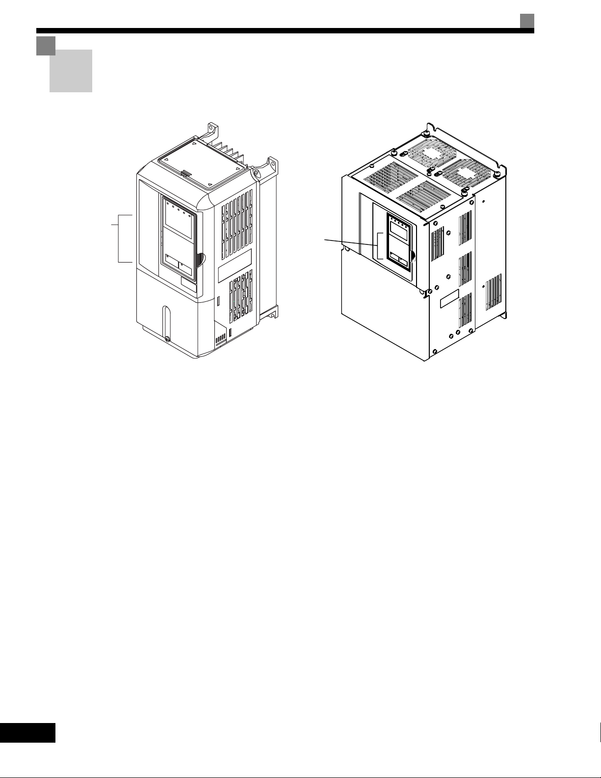
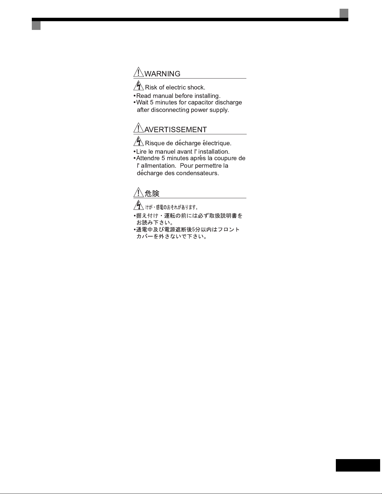
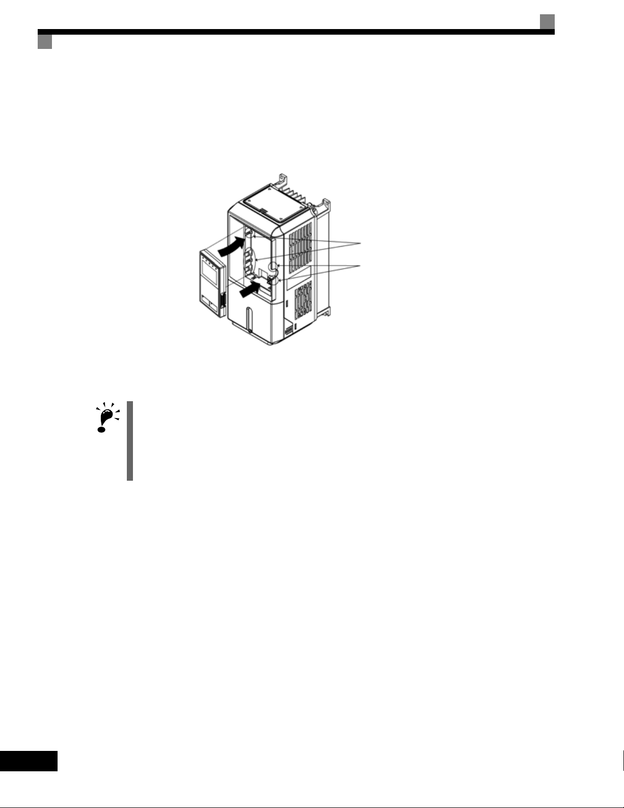
Warning Information and Position
There is warning information on the Drive in the position shown in the following illustration.
Always heed the warnings.
Warning
information
position
Warning
information
position
Illustration shows the CIMR-G7U20P4
Warning Information
Illustration shows the CIMR-G7U2018
iv
Page 6
!"##!$!"
% %
& ' (
( )
(
(
(
(
v
Page 7

Registered Trademarks
The following registered trademarks are used in this manual.
• DeviceNet is a registered trademark of the ODVA (Open DeviceNet Vendors Association, Inc.).
• ControlNet is a registered trademark of ControlNet International, Ltd.
• LONworks is a registered trademark of the Echelon.
• MODBUS is a registered trademark of the MODBUS.org.
vi
Page 8

Contents
1 Handling Drives ...................................................................... 1-1
Varispeed G7 Introduction............................................................................1-2
Varispeed G7 Models .....................................................................................................1-2
Confirmations upon Delivery ........................................................................1-3
Checks............................................................................................................................1-3
Nameplate Information ...................................................................................................1-3
Component Names.........................................................................................................1-5
Exterior and Mounting Dimensions...............................................................1-7
Open Chassis Drives (IP00) ...........................................................................................1-7
NEMA Type 1 Drives (IP 20)...........................................................................................1-8
Checking and Controlling the Installation Site ............................................1-10
Installation Site .............................................................................................................1-10
Controlling the Ambient Temperature ...........................................................................1-10
Protecting the Drive from Foreign Matter......................................................................1-10
Installation Orientation and Space..............................................................1-11
Removing and Attaching the Terminal Cover .............................................1-12
Removing the Terminal Cover ......................................................................................1-12
Attaching the Terminal Cover........................................................................................1-13
Removing/Attaching the Digital Operator and Front Cover ........................1-14
Models CIMR-G7U20P4 thru 2015 and 40P4 thru 4015 ..............................................1-14
Models CIMR-G7U2018 thru 2110 and 4018 thru 4300 ...............................................1-17
2 Wiring....................................................................................... 2-1
Connection Diagram.....................................................................................2-2
Terminal Block Configuration........................................................................2-4
Wiring Main Circuit Terminals .......................................................................2-5
Applicable Wire Sizes and Closed-loop Connectors ......................................................2-5
Main Circuit Terminal Functions ...................................................................................2-13
Main Circuit Configurations...........................................................................................2-14
Standard Connection Diagrams....................................................................................2-15
Wiring the Main Circuits................................................................................................2-16
Wiring Control Circuit Terminals .................................................................2-22
Wire Sizes and Closed-loop Connectors......................................................................2-22
Control Circuit Terminal Functions ...............................................................................2-23
Control Circuit Terminal Connections ...........................................................................2-29
vii
Page 9

Control Circuit Wiring Precautions ............................................................................... 2-30
Control Circuit Wire Sizes ............................................................................................ 2-30
Wire Checks ................................................................................................................. 2-30
Installing and Wiring Option Cards............................................................. 2-31
Option Card Models and Specifications ....................................................................... 2-31
Installation ....................................................................................................................2-32
PG Speed Control Card Terminals and Specifications ................................................. 2-33
Wiring ........................................................................................................................... 2-36
Wiring Terminal Blocks................................................................................................. 2-40
Selecting the Number of PG (Encoder) Pulses............................................................ 2-41
3 Digital Operator and Modes....................................................3-1
Digital Operator ............................................................................................ 3-2
Digital Operator Display ................................................................................................. 3-2
Digital Operator Keys ..................................................................................................... 3-3
Modes ..........................................................................................................3-5
Drive Modes ................................................................................................................... 3-5
Switching Modes ............................................................................................................ 3-6
Drive Mode .....................................................................................................................3-7
Quick Programming Mode.............................................................................................. 3-9
Advanced Programming Mode..................................................................................... 3-10
Verify Mode .................................................................................................................. 3-13
Autotuning Mode .......................................................................................................... 3-14
4 Trial Operation .........................................................................4-1
Trial Operation Procedure ............................................................................ 4-2
Trial Operation Procedures ..........................................................................4-3
Setting the Power Supply Voltage Jumper (380-480V Class Drives of 4055 or Higher) 4-3
Power ON ....................................................................................................................... 4-3
Checking the Display Status .......................................................................................... 4-4
Basic Settings................................................................................................................. 4-5
Settings for the Control Methods.................................................................................... 4-7
Autotuning ......................................................................................................................4-9
Application Settings...................................................................................................... 4-14
No-load Operation ........................................................................................................ 4-14
Loaded Operation......................................................................................................... 4-15
Check and Recording User Parameters.......................................................................4-16
Adjustment Suggestions ............................................................................ 4-17
viii
Page 10

5 User Parameters ..................................................................... 5-1
User Parameter Descriptions .......................................................................5-2
Description of User Parameter Tables............................................................................5-2
Digital Operation Display Functions and Levels ...........................................5-3
User Parameters Settable in Quick Programming Mode................................................5-4
User Parameter Tables...............................................................................5-10
A: Setup Settings..........................................................................................................5-10
Application Parameters: b.............................................................................................5-12
Autotuning Parameters: C ............................................................................................5-22
Reference Parameters: d..............................................................................................5-28
Motor Setup Parameters: E ..........................................................................................5-34
Option Parameters: F ...................................................................................................5-41
Terminal Function Parameters: H.................................................................................5-50
Protection Function Parameters: L ...............................................................................5-61
N: Special Adjustments.................................................................................................5-74
Digital Operator Parameters: o .....................................................................................5-80
T: Motor Autotuning ......................................................................................................5-84
U: Monitor Parameters..................................................................................................5-86
Factory Settings that Change with the Control Method (A1-02) ...................................5-96
Factory Settings that Change with the Drive Capacity (o2-04)...................................5-102
6 Parameter Settings by Function............................................ 6-1
Frequency Reference ...................................................................................6-2
Selecting the Frequency Reference Source...................................................................6-2
Using Multi-Step Speed Operation .................................................................................6-5
Run Command .............................................................................................6-7
Selecting the Run Command Source .............................................................................6-7
Stopping Methods.........................................................................................6-9
Selecting the Stopping Method when a Stop Command is Sent.....................................6-9
Using the DC Injection Brake........................................................................................6-13
Using an Emergency Stop ............................................................................................6-14
Acceleration and Deceleration Characteristics...........................................6-15
Setting Acceleration and Deceleration Times...............................................................6-15
Accelerating and Decelerating Heavy Loads (Dwell Function).....................................6-19
Preventing the Motor from Stalling During Acceleration (Stall Prevention During
Acceleration Function)..................................................................................................6-20
Preventing Overvoltage During Deceleration (Stall Prevention During Deceleration
Function).......................................................................................................................6-22
Adjusting Frequency References ...............................................................6-24
Adjusting Analog Frequency References .....................................................................6-24
Operation Avoiding Resonance (Jump Frequency Function).......................................6-27
Adjusting Frequency Reference Using Pulse Train Inputs ...........................................6-29
ix
Page 11

Speed Limit (Frequency Reference Limit Function)...................................6-30
Limiting Maximum Output Frequency........................................................................... 6-30
Limiting Minimum Frequency ....................................................................................... 6-31
Improved Operating Efficiency ................................................................... 6-32
Reducing Motor Speed Fluctuation (Slip Compensation Function).............................. 6-32
Compensating for Insufficient Torque at Startup and Low-speed Operation
(Torque Compensation)................................................................................................6-35
Hunting-prevention Function ........................................................................................6-37
Stabilizing Speed (Speed Feedback Detection Function) ............................................ 6-38
Machine Protection .................................................................................... 6-39
Reducing Noise and Leakage Current ......................................................................... 6-39
Limiting Motor Torque (Torque Limit Function) ............................................................6-42
Preventing Motor Stalling During Operation................................................................. 6-44
Changing Stall Prevention Level during Operation Using an Analog Input .................. 6-45
Detecting Motor Torque................................................................................................ 6-45
Changing Overtorque and Undertorque Detection Levels Using an Analog Input ....... 6-50
Motor Overload Protection ........................................................................................... 6-51
Setting Motor Protection Operation Time .....................................................................6-53
Motor Overheating Protection Using PTC Thermistor Inputs ....................................... 6-54
Limiting Motor Rotation Direction ................................................................................. 6-56
Continuing Operation ................................................................................. 6-57
Restarting Automatically After Power Is Restored........................................................ 6-57
Speed Search............................................................................................................... 6-59
Continuing Operation at Constant Speed When Frequency Reference Is Lost ........... 6-65
Restarting Operation After Transient Error (Auto Restart Function) ............................ 6-66
Drive Protection.......................................................................................... 6-67
Performing Overheating Protection on Mounted Braking Resistors............................. 6-67
Reducing Drive Overheating Pre-Alarm Warning Levels ............................................. 6-68
Input Terminal Functions ............................................................................ 6-69
Temporarily Switching Operation between Digital Operator and Control Circuit
Terminals...................................................................................................................... 6-69
Blocking Drive Outputs (Baseblock Commands) ......................................................... 6-70
Stopping Acceleration and Deceleration (Acceleration/Deceleration Ramp Hold)....... 6-71
Raising and Lowering Frequency References Using Contact Signals (UP/DOWN) .... 6-72
Accelerating and Decelerating Constant Frequencies in the Analog References
(+/- Speed) ................................................................................................................... 6-75
Hold Analog Frequency Using User-set Timing ........................................................... 6-76
Switching Operations between a Communications Option Card and Control Circuit
Terminals...................................................................................................................... 6-76
Jog Frequency Operation without Forward and Reverse Commands (FJOG/RJOG) . 6-77
Stopping the Drive by Notifying Programming Device Errors to the Drive
(External Fault Function) .............................................................................................. 6-78
x
Page 12

Monitor Parameterss ..................................................................................6-79
Using the Analog Monitor Parameters..........................................................................6-79
Using Pulse Train Monitor Contents.............................................................................6-82
Individual Functions....................................................................................6-84
Using MODBUS Communications................................................................................6-84
Using the Timer Function..............................................................................................6-97
Using PID Control .........................................................................................................6-98
Energy-saving.............................................................................................................6-107
Setting Motor Parameters...........................................................................................6-108
Setting the V/f Pattern.................................................................................................6-111
Torque Control............................................................................................................6-120
Speed Control (ASR) Structure...................................................................................6-128
Droop Control Function...............................................................................................6-134
Zero-servo Function....................................................................................................6-135
Digital Operator Functions ........................................................................6-139
Setting Digital Operator Functions..............................................................................6-139
Copying Parameters ...................................................................................................6-143
Prohibiting Writing Parameters from the Digital Operator...........................................6-148
Setting a Password.....................................................................................................6-149
Displaying User-set Parameters Only.........................................................................6-149
Options .....................................................................................................6-151
Performing Speed Control with PG.............................................................................6-151
Using Digital Output Cards .........................................................................................6-156
Using an Analog Reference Card...............................................................................6-159
Using a Digital Reference Card ..................................................................................6-159
7 Troubleshooting ..................................................................... 7-1
Protective and Diagnostic Functions ............................................................7-2
Fault Detection................................................................................................................7-2
Alarm Detection ..............................................................................................................7-9
Operation Errors ...........................................................................................................7-13
Errors During Autotuning .............................................................................................7-15
Errors when Using the Digital Operator Copy Function................................................7-17
Troubleshooting ..........................................................................................7-18
If Parameters Cannot Be Set........................................................................................7-18
If the Motor Does Not Operate......................................................................................7-19
If the Direction of the Motor Rotation is Reversed ........................................................7-21
If the Motor Does Not Put Out Torque or If Acceleration is Slow..................................7-21
If the Motor Operates Higher Than the Reference .......................................................7-22
If the Slip Compensation Function Has Low Speed Precision......................................7-22
If There is Low Speed Control Accuracy at High-speed Rotation in Open-loop Vector
Control Mode ................................................................................................................7-22
xi
Page 13

If Motor Deceleration is Slow........................................................................................ 7-23
If the Motor Overheats.................................................................................................. 7-24
If There is Noise When the Drive is Started or From an AM Radio .............................. 7-24
If the Ground Fault Interrupter Operates When the Drive is Run................................. 7-25
If There is Mechanical Oscillation................................................................................. 7-25
If the Motor Rotates Even When Drive Output is Stopped ........................................... 7-26
If 0 V is Detected When the Fan is Started, or Fan Stalls............................................. 7-26
If Output Frequency Does Not Rise to Frequency Reference...................................... 7-27
8 Maintenance and Inspection ..................................................8-1
Maintenance and Inspection ........................................................................8-2
Outline of Maintenance .................................................................................................. 8-2
Daily Inspection .............................................................................................................. 8-2
Periodic Inspection ......................................................................................................... 8-2
Periodic Maintenance of Parts ....................................................................................... 8-3
Cooling Fan Replacement Outline ................................................................................. 8-4
Removing and Mounting the Control Circuit Terminal Card........................................... 8-6
9 Specifications ..........................................................................9-1
Standard Drive Specifications ...................................................................... 9-2
Specifications by Model.................................................................................................. 9-2
Common Specifications.................................................................................................. 9-4
Specifications of Options and Peripheral Devices........................................ 9-5
10 Appendix ................................................................................10-1
Varispeed G7 Control Modes .....................................................................10-2
Control Modes and Features........................................................................................ 10-2
Control Modes and Applications................................................................................... 10-6
Drive Application Precautions .................................................................... 10-7
Selection.......................................................................................................................10-7
Installation ....................................................................................................................10-8
Settings ........................................................................................................................10-8
Handling ....................................................................................................................... 10-9
Motor Application Precautions ................................................................. 10-10
Using the Drive for an Existing Standard Motor ......................................................... 10-10
Using the Drive for Special Motors ............................................................................. 10-11
Power Transmission Mechanism (Speed Reducers, Belts, and Chains) ................... 10-11
xii
Conformance to CE Markings .................................................................. 10-12
CE Markings............................................................................................................... 10-12
Requirements for Conformance to CE Markings........................................................ 10-12
User Parameters ...................................................................................... 10-19
Page 14

1
Handling Drives
This chapter describes the checks required upon receiving or installing an Drive.
Varispeed G7 Introduction ...........................................1-2
Confirmations upon Delivery........................................1-3
Exterior and Mounting Dimensions..............................1-7
Checking and Controlling the Installation Site ...........1-10
Installation Orientation and Space ............................. 1-11
Removing and Attaching the Terminal Cover ............1-12
Removing/Attaching the Digital Operator
and Front Cover.........................................................1-14
Page 15
Varispeed G7 Introduction
Varispeed G7 Models
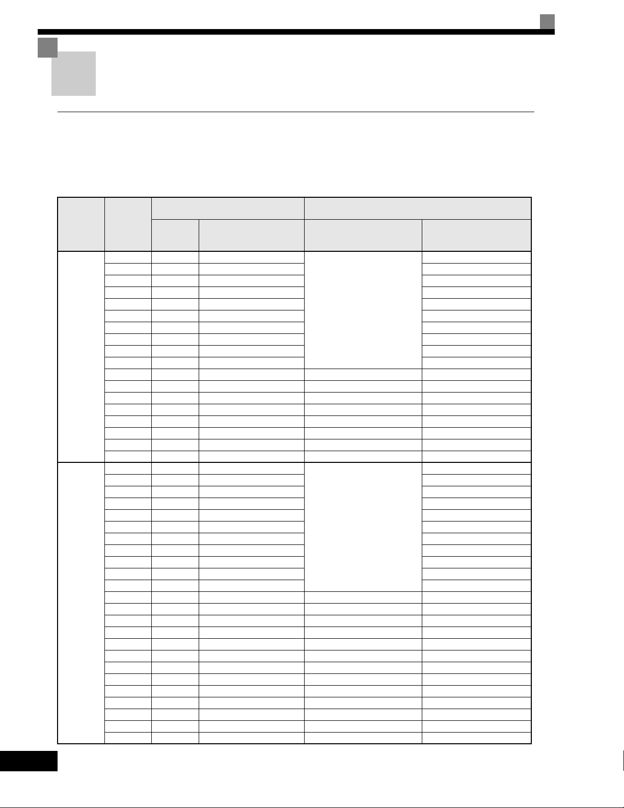
The Varispeed-G7 Series of Drives included two Drives in two voltage classes: 200-240V and 380-480V. Maximum motor
capacities vary from 20P4 to 2110 and 40P4 to 4300 (42 models).
Table 1.1 Varispeed G7 Models
Voltage
Class
200-240V
class
380-480V
class
Maximum
Motor
Capacity
kW
0.4 1.2 CIMR-G7U20P4
0.75 2.3 CIMR-G7U20P7 20P71
1.5 3.0 CIMR-G7U21P5 21P51
2.2 4.6 CIMR-G7U22P2 22P21
3.7 6.9 CIMR-G7U23P7 23P71
5.5 10 CIMR-G7U25P5 25P51
7.5 13 CIMR-G7U27P5 27P51
11 19 CIMR-G7U2011 2011
15 25 CIMR-G7U2015 20151
18.5 30 CIMR-G7U2018 20181
22 37 CIMR-G7U2022 - 20220
30 50 CIMR-G7U2030 20300 -
37 61 CIMR-G7U2037 20370 -
45 70 CIMR-G7U2045 20450 -
55 85 CIMR-G7U2055 20550 -
75 110 CIMR-G7U2075 20750 -
90 140 CIMR-G7U2090 20900 -
110 160 CIMR-G7U2110 21100 -
0.4 1.4 CIMR-G7U40P4
0.75 2.6 CIMR-G7U40P7 40P71
1.5 3.7 CIMR-G7U41P5 41P51
2.2 4.7 CIMR-G7U42P2 42P21
3.7 6.9 CIMR-G7U43P7 43P71
4.0 8.4 CIMR-G7U44P0 44P01
5.5 11 CIMR-G7U45P5 45P51
7.5 16 CIMR-G7U47P5 47P51
11 21 CIMR-G7U4011 40111
15 26 CIMR-G7U4015 40151
18.5 32 CIMR-G7U4018 40181
22 40 CIMR-G7U4022 - 40221
30 50 CIMR-G7U4030 - 40301
37 61 CIMR-G7U4037 - 40371
45 74 CIMR-G7U4045 - 40451
55 98 CIMR-G7U4055 40550 -
75 130 CIMR-G7U4075 40750 -
90 150 CIMR-G7U4090 40900 -
110 180 CIMR-G7U4110 41100 -
132 210 CIMR-G7U4132 41320 -
1
60 230 CIMR-G7U4160 41600 -
185 280 CIMR-G7U4185 41850 -
220 340 CIMR-G7U4220 42200 -
300 460 CIMR-G7U4300 43000 -
Output
Capacity
kVA
Va r i sp ee d G7
Basic Model Number
(Always specify through the protective structure when ordering.)
Open Chassis
(IEC IP00)
CIMR-G7
Remove the top and bottom
covers from the Enclosed
Wall-mounted model.
Remove the top and bottom
covers from the Enclosed
Wall-mount model.
Specifications
Enclosed Wall-mounted
(IEC IP20, NEMA 1)
CIMR-G7
20P41
40P41
1-2
Page 16

Confirmations upon Delivery
Checks
Check the following items as soon as the Drive is delivered.
Table 1.2 Checks
Item Method
Has the correct model of Drive been
delivered?
Is the Drive damaged in any way?
Check the model number on the nameplate on the side of the Drive.
Inspect the entire exterior of the Drive to see if there are any scratches or
other damage resulting from shipping.
Confirmations upon Delivery
Are any screws or other components
loose?
Use a screwdriver or other tools to check for tightness.
If you find any irregularities in the above items, contact the agency from which you purchased the Drive or
your Yaskawa representative immediately.
Nameplate Information
There is a nameplate attached to the side of each Drive. The nameplate shows the model number, specifications, lot number, serial number, and other information on the Drive.
Example Nameplate
The following nameplate is an example for a standard Drive: 3-phase, 200-240Vac, 0.4kW, IEC IP20 and
NEMA 1 standards.
Drive model
Input specifications
Input specifications
Output
specifications
Lot number
Serial number
GU
Drive
specifications
Mass
Fig 1.1 Nameplate
1-3
Page 17
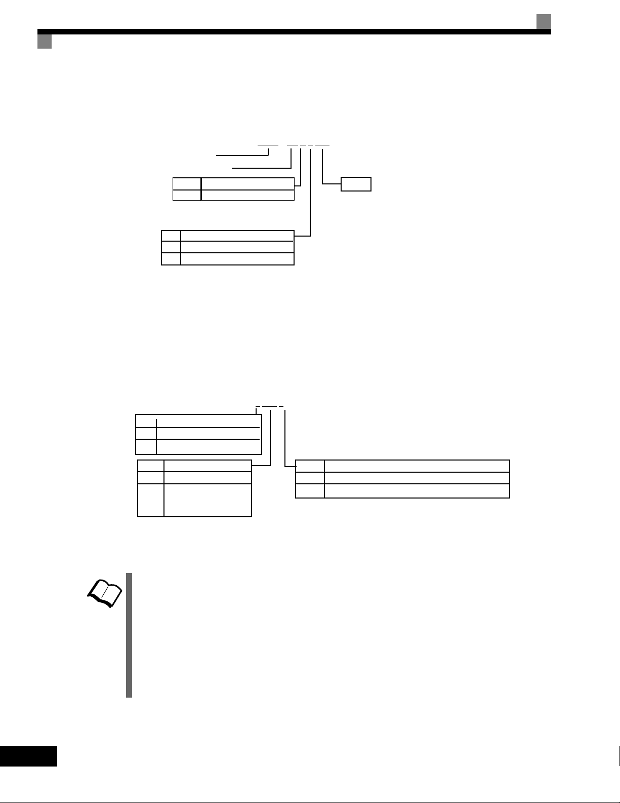
Drive Model Numbers
The model number of the Drive on the nameplate indicates the specification, voltage class, and maximum
motor capacity of the Drive in alphanumeric codes.
CIMR – G7 U 2 0P4
AC Drive
G7 Family
No.
U
No. Voltage
2
4
Spec
UL Specification
3-phase, 208-240Vac
3-phase, 480Vac
Fig 1.2 Drive Model Numbers
Rating
Drive Specifications
The SPEC number on the nameplate indicates the voltage, Drive rating, enclosure type, and the revision code
of the Drive in alphanumeric codes. The SPEC number for Drives that have custom features, i.e. CASE
software, will have a SPEC number that indicates the custom features installed.
TERMS
0P4 1
2
No.
2
4
No.
0P4 0.4kW
0P7 0.75kW
to
300
“P” indicates the decimal point
Voltage
AC input, 3-phase, 200-240V
AC input, 3-phase, 380-480V
Max. Motor Capacity
to
300kW *
No.
0
1
Enclosure Type
Open chassis (IEC IP00)
NEMA Type 1 (IEC IP20)
Fig 1.3 Drive Specifications
Open Chassis Type (IEC IP00)
Protected so that parts of the human body cannot reach electrically charged parts from the front when the
Drive is mounted in a control panel.
NEMA Type 1 (IEC IP20)
The Drive is shielded from the exterior, and can thus be mounted to the interior wall of a standard building
(not necessarily enclosed in a control panel). The protective structure conforms to the standards of NEMA 1
in the USA.
Top protective cover must be installed to conform with IEC IP20 and NEMA 1 Type 1 requirements. Refer to
Fig. 1.4 for details.
1-4
Page 18
Confirmations upon Delivery
NPJT31278-1-0
CAUTION
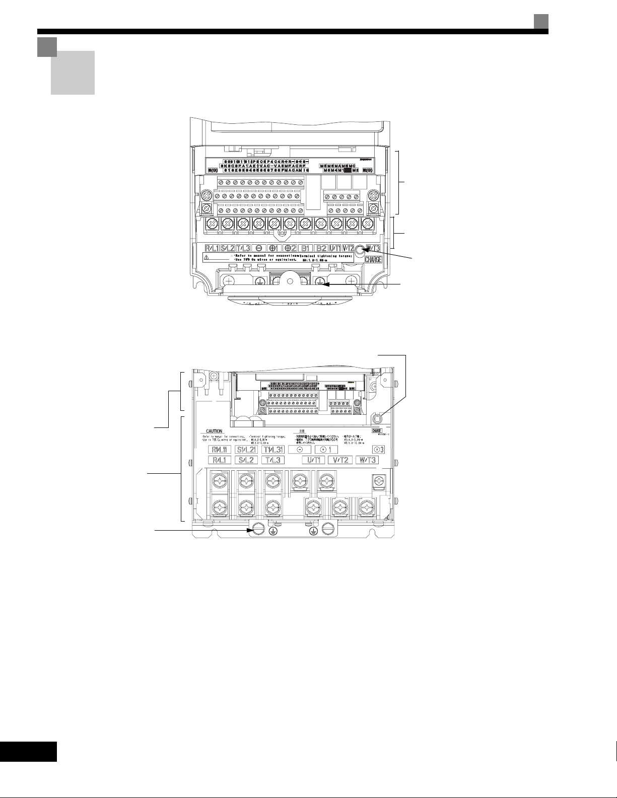
Component Names
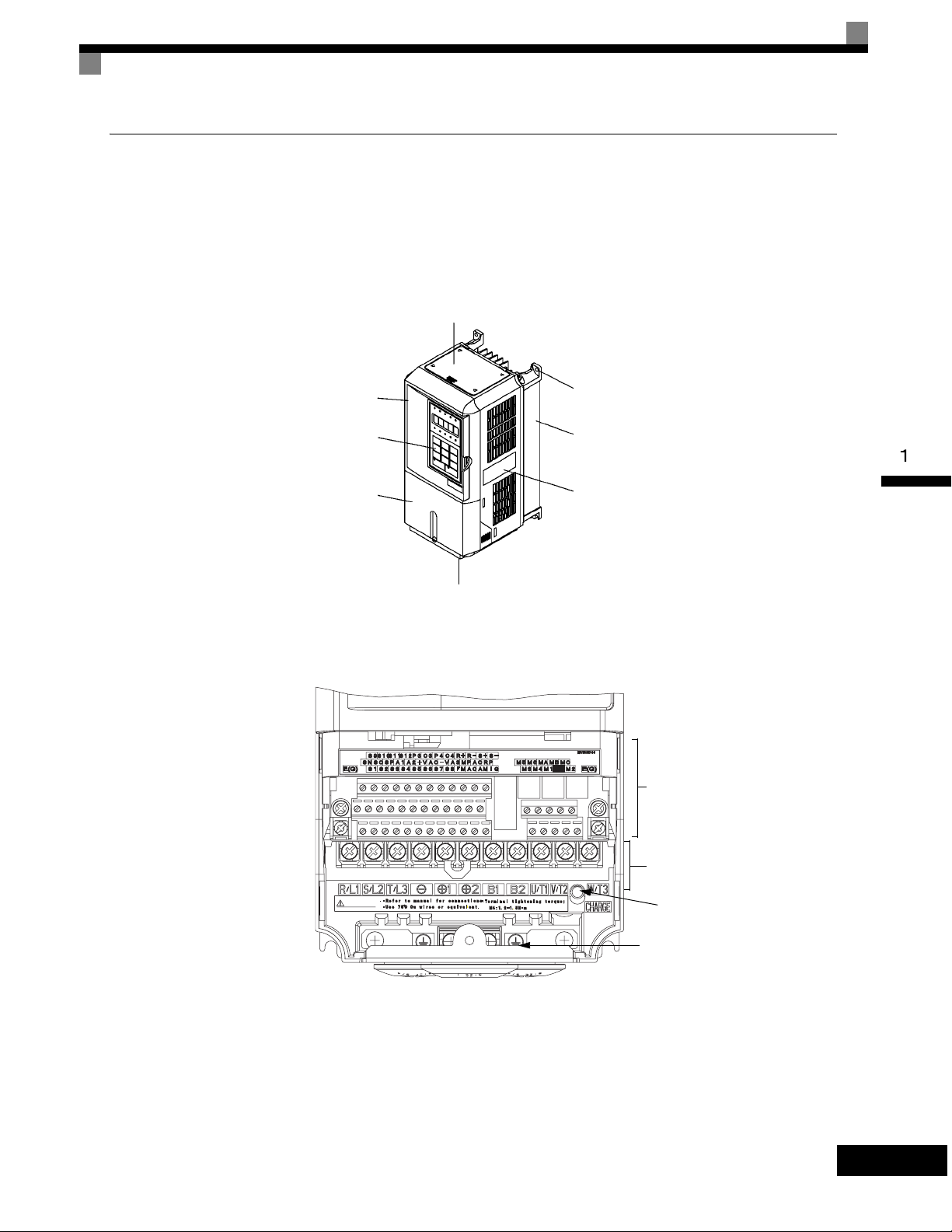
Models CIMR-G7U20P4 thru 2015 and 40P4 thru 4015
The external appearance and component names of the Drive are shown in Fig 1.4. The Drive with the terminal
cover removed is shown in Fig 1.5.
Top protective cover
[Required for NEMA Type 1 (IEC IP20)]
Front cover
Digital Operator
Terminal cover
Mounting hole
Diecast case
Nameplate
Bottom protective cover
Fig 1.4 Drive Appearance
Control circuit terminals
CAUTION
Fig 1.5 Terminal Arrangement
NPJT31278-1-0
Main circuit terminals
Charge indicator
Ground terminal
1-5
Page 19
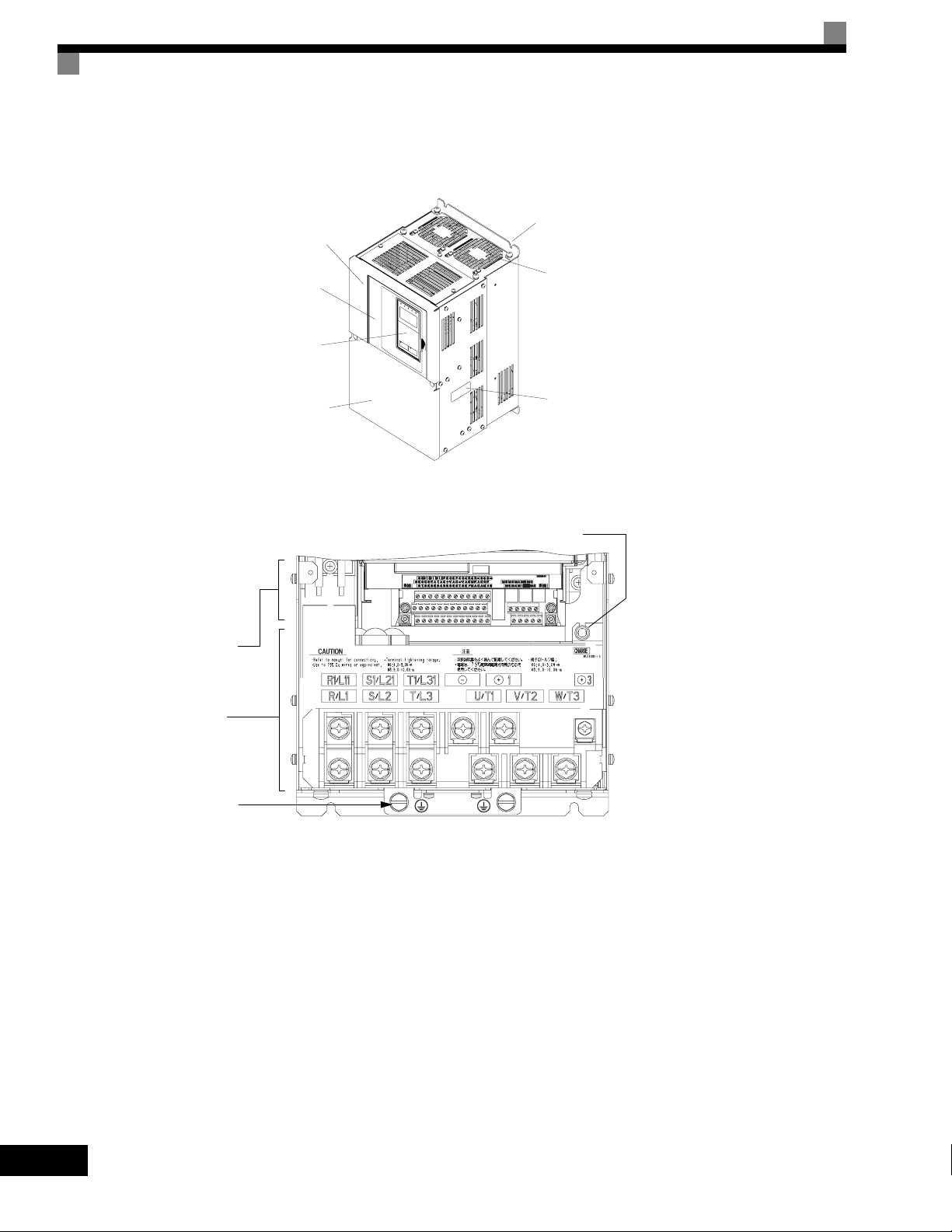
Models CIMR-G7U2018 thru 2110 and 4018 thru 4300
The external appearance and component names of the Drive are shown in Fig 1.6. The Drive with the terminal
cover removed is shown in Fig 1.7.
Mounting holes
Drive cover
Control circuit
terminals
Main circuit
terminals
Front cover
Digital Operator
Terminal cover
Cooling fan
Nameplate
Fig 1.6 Drive Appearance
Charge indicator
1-6
Ground terminal
Fig 1.7 Terminal Arrangement
Page 20

Exterior and Mounting Dimensions
Open Chassis Drives (IP00)
Exterior diagrams of the Open Chassis Drives are shown below.
Exterior and Mounting Dimensions
W1
W
Models CIMR-G7U20P4 thru 2015 and 40P4 thru 4015
4-d
H1H2DH
D1
3
t1
(5)
H
H1
CHARGE
H2
∗
W
(5)
∗
D
t1
D1
Front View Side View Bottom View
Models CIMR-G7U2018 thru 2110 and 4018 thru 4160
1-7
Page 21
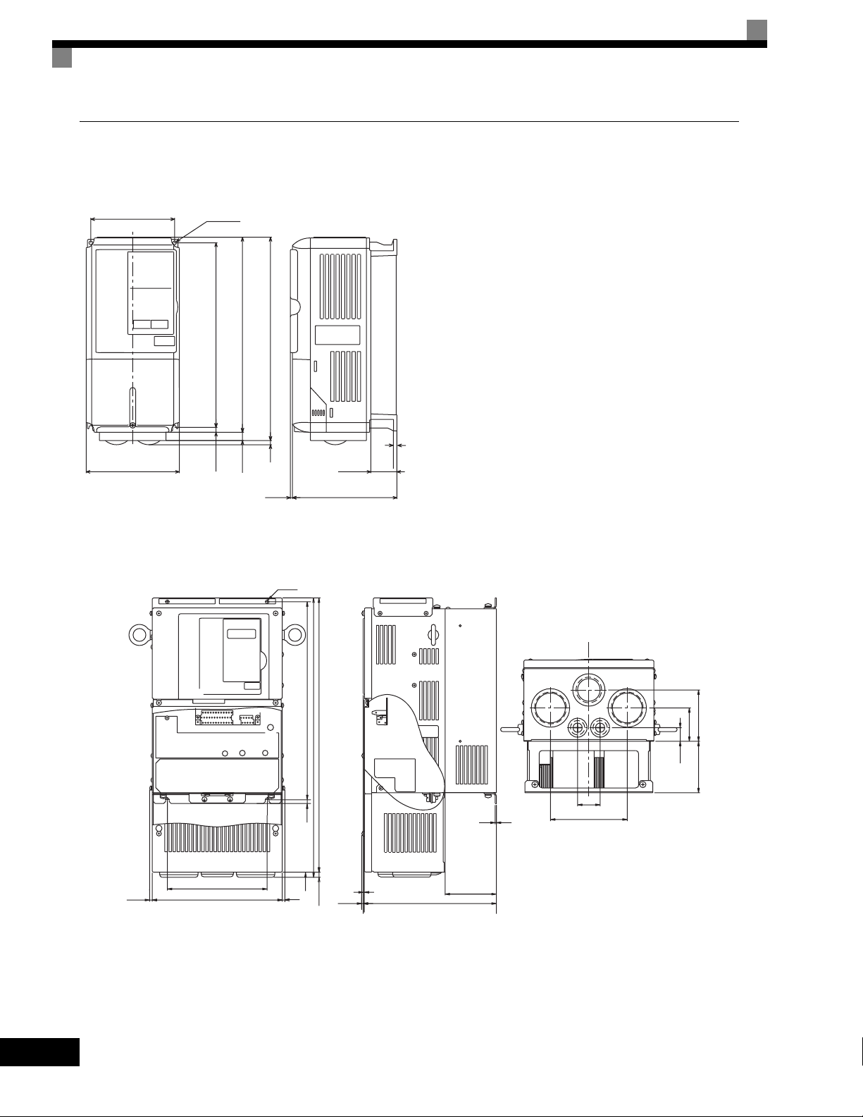
NEMA Type 1 Drives (IP 20)
Exterior diagrams of the Enclosed Wall-mounted Drives (NEMA1 Type 1) are shown below.
W1
4-d
H1H2DH0
4 H
W
H3
D1
3
Models CIMR-G7U20P4 thru 2015 and 40P4 thru 4015
4-d
t1
1-8
(5)*
H
H0
H1
CHARGE
-
+
1
3
+
W1
W
(5)*
H2
H3
max.10
(5)
D
t1
D1
Front View Side View Bottom View
Models CIMR-G7U2018 thru 2075 and 4018 thru 4160
Page 22
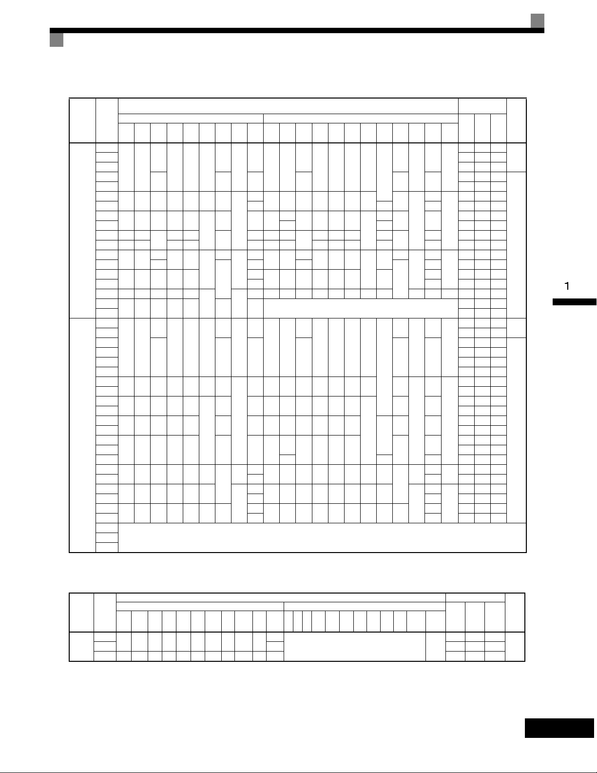
Table 1.3 Drive Dimensions (mm) and Masses (kg)
Model
Voltage
CIMR-
Class
G7U
W H D W1H1H2D1 t1
20P4
140 280
21P5 58 47 105
22P2
23P7 122 64 186
25P5
200 300 197 186 285 8 65.5
27P5 7 0 7 263 112 375
2011
240 350 207 216 335
200-240V
2015 380 30 473 174 647
(3-phase)
2018 250 400
2022 275 450 220 435 24 279 613 220 450 435 165 27 679 257 936
2030
375 600
2037 330
2045
450 725 350 325 700
2055 87 95 1474 607 2081
2075 500 850 360 370 820
2090
575 885 380 445 855 140 150 ---
2110 2389 1194 3583
40P4
40P7 21 44 65
41P5
140 280
42P2 41 49 90
43P7 77 63 140
44P0 100 66 166
45P5
200 300 197 186 285 8 65.5
47P5 197 107 304
4011
240 350 207 216 335
4015 311 135 446
4018
275 450 258 220 435 100 26 279 535 258 220 450 435
380-480V
4022 516 210 726
(3-phase)
4030
325 550 283 260 535 105 37 329
4037 737 285 1022
4045 715 165 40 929 340 1269
4055
450 725 348 325 700 12.5
4075 91 99 1554 597 2151
4090
500 850 358 370 820 15
4110 127 137 2299 928 3227
4132
575 916 378 445 855 45.8 140
4160 175 185 3614 1501 5115
4185
4300
* Same for Open Chassis and Enclosed Wall-mounted Drives
Open Chassis (IP00) Enclosed Wall-mounted (NEMA Type 1)
157
126 266 7
177 59 4 177 59 4
260
300
195 385
250 575
7.5
12.5
15 4.5
157
126 266 7
177 59 4.5 177 59 4.5
7.5
Dimensions (mm)
Approx
W H D W1H0H1H2H3D1 t1
Mass
39
78 11 240
100
100
130
3
5
6
2.3
21 254 535
57
63 328
3.2
86
140 280
126 280 266 7
200 300 197 186 300 285 8 65.5
157
350
207 216 350 335
195 400 385 135
260
380 809
298
250 600 575
453 1027 348 325 725 700 302
108 504 1243 361 370 850 820 15 393 4.5 114 M12 2009 823 2832
39
3.5
5
140 280
157
126 280 266 7
7 200 300 197 186 300 285 8 65.5
78 10 240 350 207 216 350 335
2.3
635
285 260 550 535 105
90
3.2
130
4.5
453 1027 348 325 725 700 12.5 302
109
504 1243 358 370 850 820 15 393
165
579 1324 378 445 916 855 45.8 408 140
See Table 1.44220
Exterior and Mounting Dimensions
Heat Generation
Mount-
External Internal
ing
Holes*
3
M5
6
187 87 274
357 136 493
M6
24 599 241 840
62
68 1080 434 1514
94 1291 510 1801
878 362 1240
M10
1660 871 2531
M5
6
132 80 212
246 116 362
M6
354 174 528
39
98
633 246 879
1239 488 1727
M10
1928 762 2690
M12
7.5
12.5
7.5
0
0
209
0
85
Approx
Mass
39
5
2.3
78 11
100
100
3.2
130
39
5
78 10
2.3
100 29
3.2
130
4.5
3.5
127
175 2612 1105 3717
(W)
Tot al
Heat
21 36 57
83 53 136
10 39 49
33 46 79
Cooling
Method
Natural20P7 43 42 85
Fan
Natural
Fan
Table 1.4 480Vac (185 to 300 kW) Drive Dimensions (mm) and Masses (kg)
Model
Voltage
CIMR-
Class
G7U
W H D W1W2W3 H1 H2 D1 t1
4185
380-
480V
(3-phase)
710 1305 413 540 240 270 1270 15 125.5 4.5
4300 916 1475 413 730 365 365 1440 15 125.5 4.5 415 6749 2941 9690
Open Chassis (IP00) Enclosed Wall-mounted (NEMA Type1)
Dimensions (mm) Heat Generation (W)
Approx
WHDW1W2W3H1 H2 D1 t1
Mass
Approx
Mass
Mount-
ing
Holes*
260
--- M12
External Internal
4436 1995 6431
Tot a l
Heat
Cooling
Method
Fan4220 280 5329 2205 7534
1-9
Page 23
Checking and Controlling the Installation Site
Install the Drive in the installation site described below and maintain optimum conditions.
Installation Site
Install the Drive to a non-combustible surface under the following conditions in UL Pollution Degree 2 environments. This excludes wet locations where pollution may become conductive due to moisture, and locations
containing conductive foreign matter
Table 1.5 Installation Site
Type Ambient Operating Temperature Humidity
NEMA Type 1 14° F-to- 104°F (-10-to- + 40 °C) 95% RH or less (no condensation)
Open chassis 14° F-to- 113°F (-10-to- + 45 °C) 95% RH or less (no condensation)
Protective covers are attached to the top and bottom of the Drive. It is recommended to remove the protective
covers before operating a NEMA Type 1 Drive (Models CIMR-G7U2015/4015 and smaller) in a panel to
obtain the 113° (45°C) ambient operating temperature.
Observe the following precautions when installing the Drive. Make sure to install:
• In a clean location which is free from oil mist and dust.
• In an environment where metal shavings, oil, water, or other foreign materials do not get into the Drive.
• In a location free from radioactive materials and combustible materials (e.g. wood).
• In a location free from harmful gases and liquids.
• In a location free from excessive vibration.
• In a location free from chlorides
• In a location away from direct sunlight.
1-10
Controlling the Ambient Temperature
To enhance the reliability of operation, the Drive should be installed in an environment free from extreme temperature variation. If the Drive is installed in an enclosure, use a cooling fan or air conditioner to maintain the
internal air temperature below 113°
F (45°C).
Protecting the Drive from Foreign Matter
During Drive installation and project construction, it is possible to have foreign matter such as metal shavings
or wire clippings fall inside the Drive. To prevent foreign matter from falling into the Drive, place a temporary
cover over the Drive.
Always remove the temporary cover from the Drive before start-up. Otherwise, ventilation will be reduced,
causing the Drive to overheat.
Page 24

Installation Orientation and Space
T
Install the Drive vertically so as not to reduce the cooling effect. When installing the Drive, always provide the following installation space to allow normal heat dissipation.
Installation Orientation and Space
1.97in * (50mm) minimum
1.2in
(30.5mm) minimum
1.97in (50mm) minimum
1.2in
(30.5mm) minimum
4.72in (120mm) minimum
Air
4.75in (120mm) minimum
Air
Vertical ClearanceHorizontal Clearance
* For Drive model G7U4300, this clearance dimension is 11.81in (300mm) minimum. All other models require 1.97in (50mm) minimum.
Fig 1.8 Drive Installation Orientation and Space
1. The same space is required horizontally and vertically for both Open Chassis (IP00) and Enclosed Wallmounted (IP20, NEMA 1 Type 1) Drives.
IMPORTAN
2. Always remove the protection covers before installing a 200-240 or 380-480 V Class Drive with an output
of 15 kW or less in a panel.
Always provide enough space for suspension eye bolts and the main circuit lines when installing a 200-240
or 380-480 V Class Drive with an output of 18.5 kW or more in a panel.
1-11
Page 25
Removing and Attaching the Terminal Cover
Remove the terminal cover to wire cables to the control circuit and main circuit terminals.
Removing the Terminal Cover
Models CIMR-G7U20P4 thru 2015 and 40P4 thru 4015
Loosen the screws at the bottom of the terminal cover, press in on the sides of the terminal cover in the
directions of arrows 1, and then lift up on the terminal in the direction of arrow 2.
1
2
1
Fig 1.9 Removing the Terminal Cover (Model CIMR-G7U23P7 Shown Above)
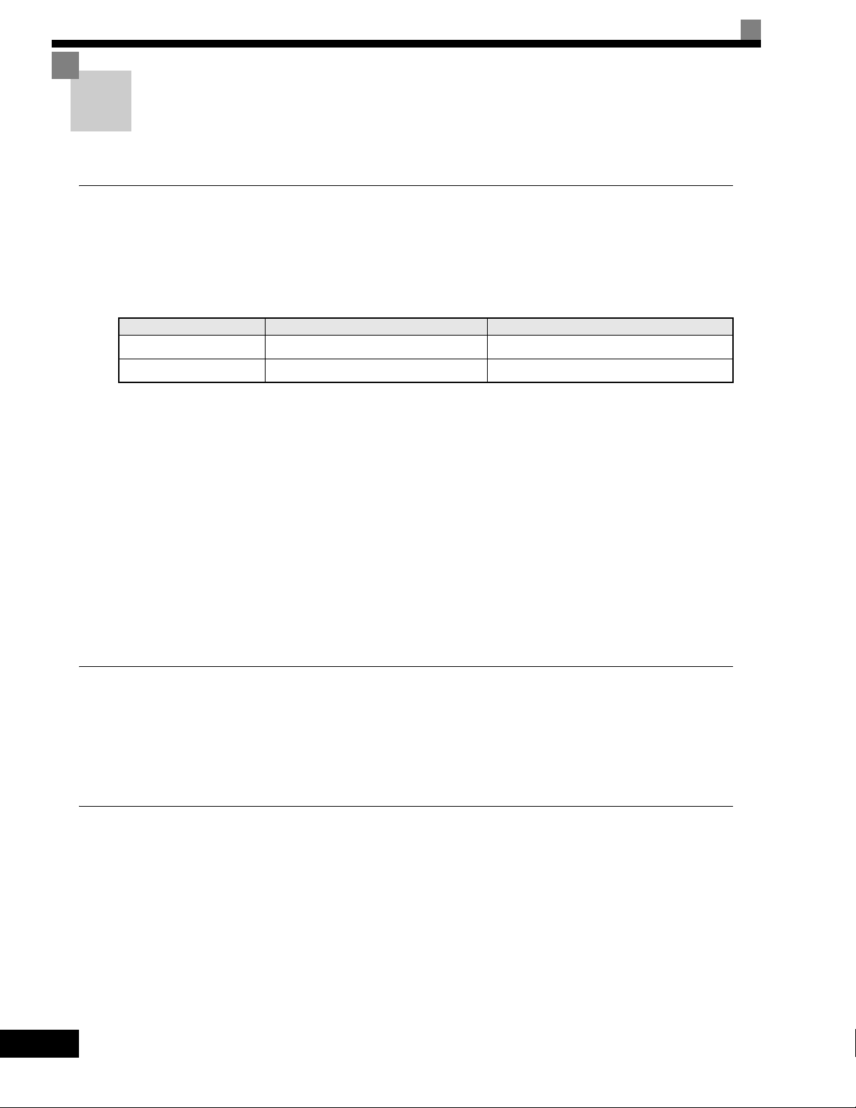
Models CIMR-G7U2018 thru 2110 and 4018 thru 4300
Loosen the screws on the left and right at the top of the terminal cover, pull out the terminal cover in the
direction of arrow 1 and then lift up on the terminal in the direction of arrow 2.
1
2
1-12
Fig 1.10 Removing the Terminal Cover (Model CIMR-G7U2018 Shown Above)
Page 26

Removing and Attaching the Terminal Cover
Attaching the Terminal Cover
After wiring the terminal block, attach the terminal cover by reversing the removal procedure.
For Models CIMR-G7U2015/4015 and smaller, insert the tab on the top of the terminal cover into the groove on the
Drive, and press in on the bottom of the terminal cover until it clicks into place.
For Drives CIMR-G7U2018/4018 and larger, insert the tab on the top of the terminal cover into the groove on the
Drive, and secure the terminal cover by lifting it up toward the top of the Drive.
1-13
Page 27
Removing/Attaching the Digital Operator and Front Cover
The methods of removing and attaching the Digital Operator and Front Cover are described in this section.
Models CIMR-G7U20P4 thru 2015 and 40P4 thru 4015
To attach optional cards or change the terminal card connector, remove the Digital Operator and front cover in
addition to the terminal cover. Always remove the Digital Operator from the front cover before removing the
terminal cover.
The removal and attachment procedures are given below.
Removing the Digital Operator
Press the lever on the side of the Digital Operator in the direction of arrow 1 to unlock the Digital Operator
and lift the Digital Operator in the direction of arrow 2 to remove the Digital Operator as shown in the following illustration.
2
Fig 1.11 Removing the Digital Operator (Model CIMR-G7U43P7 Shown Above)
1
1-14
Page 28
Removing/Attaching the Digital Operator and Front Cover
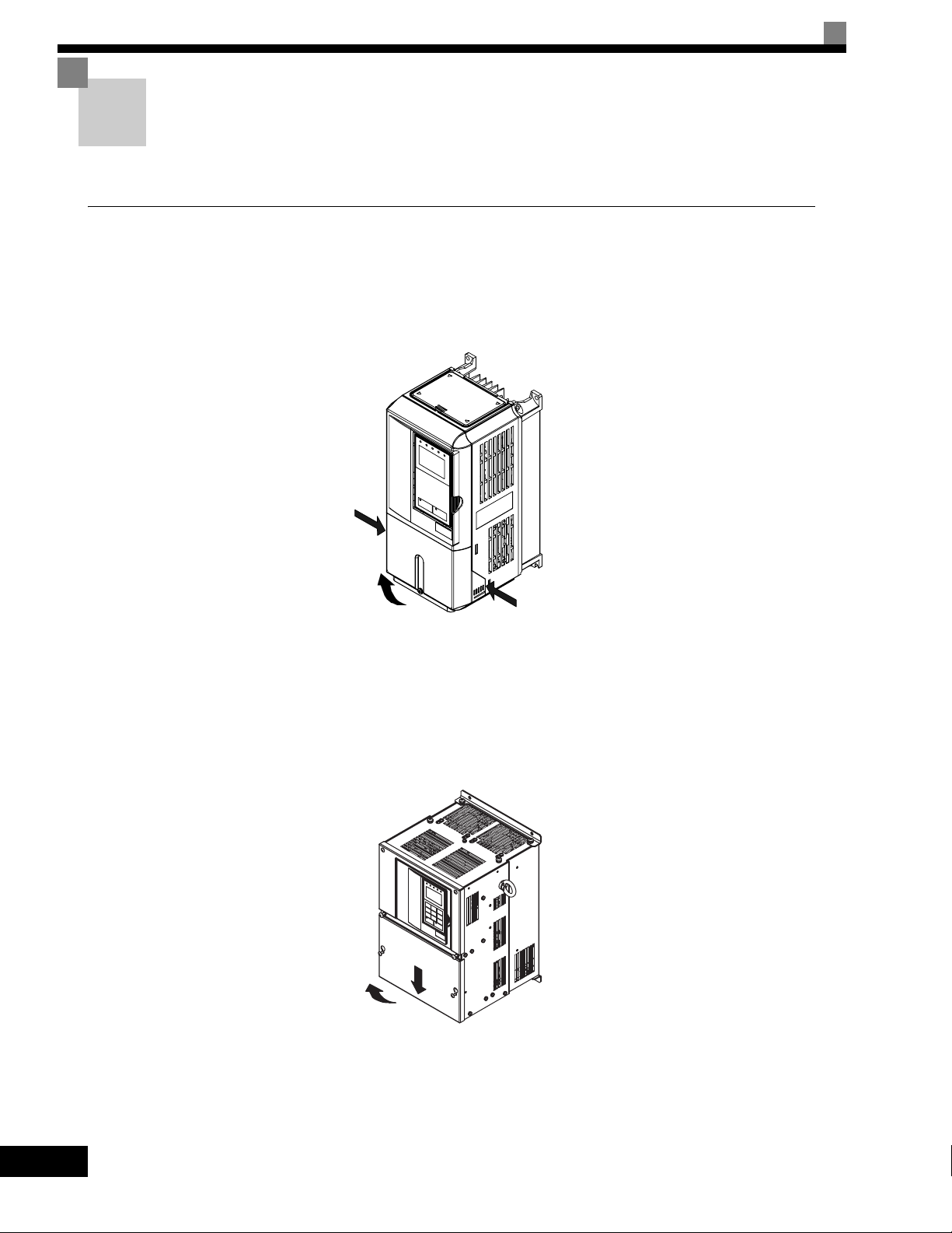
Removing the Front Cover
Press the left and right sides of the front cover in the directions of arrows 1 and lift the bottom of the cover in
the direction of arrow 2 to remove the front cover as shown in Fig. 1.12.
1
1
2
Fig 1.12 Removing the Front Cover (Model CIMR-G7U43P7 Shown Above)
Mounting the Front Cover
After wiring the terminals, mount the front cover to the Drive by performing in reverse order to the steps to
remove the front cover.
1. Do not mount the front cover with the Digital Operator attached to the front cover; otherwise, Digital
Operator may malfunction due to improper mating with control board connector.
2. Insert the tab of the upper part of the front cover into the groove of the Drive and press the lower part of the
front cover onto the Drive until the front cover snaps into place.
1-15
Page 29
Mounting the Digital Operator
T
After attaching the front cover, mount the Digital Operator onto theDrive using the following procedure.
1. Hook the Digital Operator at A (two locations) on the left side of the opening on the front cover in the
direction of arrow 1 as shown in the following illustration.
2. Press the Digital Operator in the direction of arrow 2 until it snaps in place at B (two locations).
A
1
2
Fig 1.13 Mounting the Digital Operator
B
IMPORTAN
1. Do not remove or attach the Digital Operator or mount or remove the front cover using methods other than
those described above, otherwise the Drive may break or malfunction due to imperfect contact.
2. Never attach the front cover to the Drive with the Digital Operator attached to the front cover. Imperfect
contact can result.
Always attach the front cover to the Drive by itself first, and then attach the Digital Operator to the front
cover.
1-16
Page 30

Removing/Attaching the Digital Operator and Front Cover
Models CIMR-G7U2018 thru 2110 and 4018 thru 4300
For Drive models CIMR-G7U2018 thru 2110 and 4018 thru 4300, remove the terminal cover and then use the
following procedures to remove the Digital Operator and main cover.
Removing the Digital Operator
Use the same procedure as for Drives with an output of 18.5 kW or less.
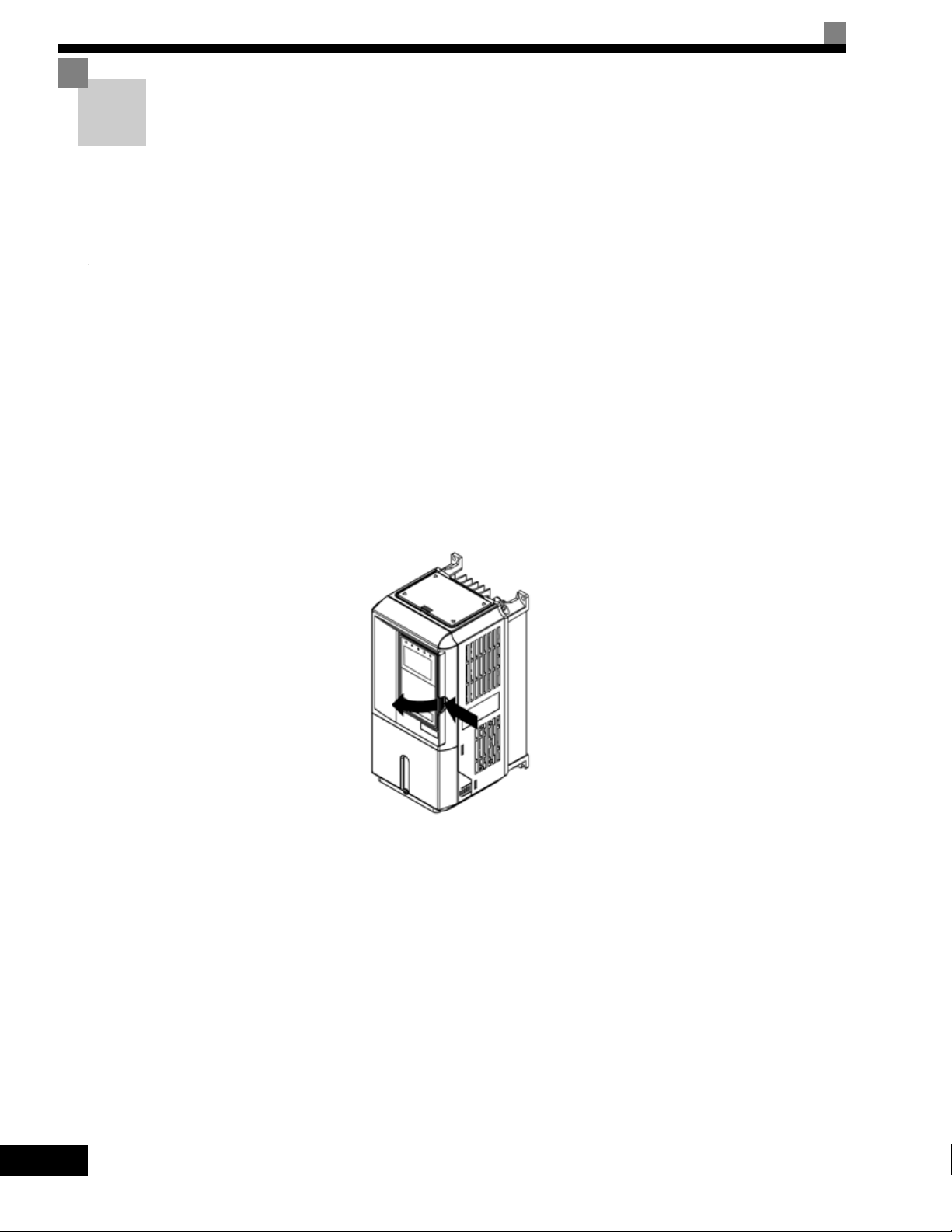
Removing the Front Cover
Loosen all screws on the front cover. Lift up at the location labelled 1 at the top of the control circuit terminal
card and move in the direction of arrow 2.
2
1
Fig 1.14 Removing the Front Cover (Model CIMR-G7U2018 Shown Above)
Attaching the Front Cover
Attach the front cover by reversing the procedure to remove it.
1. Confirm that the Digital Operator is not mounted on the front cover. If the cover is attached while the
Digital Operator is mounted to it, the Digital Operator may malfunction due to improper mating with its
connector.
2. Insert the tab on the top of the front cover into the slot on the Drive and press in on the cover until it clicks
into place on the Drive.
Attaching the Digital Operator
Use the same procedure as for Drives with an output of 18.5 kW or less.
1-17
Page 31

1-18
Page 32

2
Wiring
This chapter describes wiring terminals, main circuit terminal connections, main circuit termi-
nal wiring specifications, control circuit terminals, and control circuit wiring specifications.
Connection Diagram....................................................2-2
Terminal Block Configuration .......................................2-4
Wiring Main Circuit Terminals ......................................2-5
Wiring Control Circuit Terminals ................................2-22
Installing and Wiring Option Cards ............................2-31
Page 33
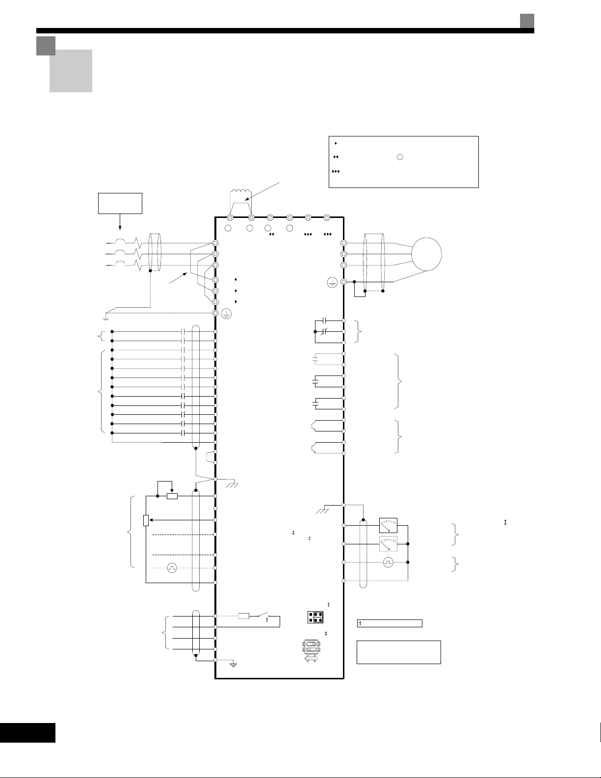
Connection Diagram
The connection diagram of the Drive is shown in Fig 2.1.
When using the Digital Operator, the motor can be operated by wiring only the main circuits.
DC Link Choke
Standard:
CIMR-G7U2018 t o 2110
CIMR-G7U4018 t o 4300
Branch circui t
protection supplied
by others.
Shorting Bar Standard:
CIMR-G7U20P4 to 2015
CIMR-G7U40P4 to 4015
UX
Remove if addi ng
external DC link
choke
12 Pulse Input Terminals R1/L11, S1/L21, T1/L31 are standard
on CIMR-G7U2018 - 2110 and CIMR-G7U4018 - 4300.
External Braking Terminal 3 is standard on CIMR-G7U2018
- 2110 and CIMR-G7U4018 - 4300.
Braking Terminals B1, B2 are standard on CIMR-G7U20P4 2015 and CIMR-G7U40P4- 4015.
+
3-Phase
Power Su pply
50/60Hz
Digital Inputs
24VDC, 8mA
Multi-function
Digital Inputs
24VDC, 8 mA
L1
L2
L3
External
Frequency
Reference
MCCB
Foward Run/Stop
Reverse Run/ Stop
External Fault
Fault Reset
Multi-Step Reference1
Multi-Step Reference2
Jog Reference
Baseblock
Multi-Step Reference3
Multi-Step Reference4
Accel / Decel Time 1
Fast-Stop N.O.
2k
Ω
Modbus RTU
Communicatio ns
RS-485/422
19.2 Kbps
Remove jumpers if
using 12 pulse input
2k
Ω
Resistor
Ω
S1-1
3
G7
Ω
(S1-2 ON)
Ω
Ω
Ω
-
(H2-01)
(H2-02)
(H2-03)
(H2-04)
(H2-05)
(S1-2 OFF)
Ω
Jumper CN15
CH1
CH2
DIP Swit ch S1
OFF ON
+1+2+
R/L1
S/L2
T/L3
R/L11
S/L21
T/L31
S1
S2
S3 (H1-01)
S4 (H1-02)
S5 (H1-03)
S6 (H1-04)
S7 (H1-05)
S8 (H1-06)
S9 (H1-07)
S10 (H1-08)
S11 (H1-09)
S12 (H1-10)
SN
SC
SP +24VDC
E(G)
+V +15VDC +/-10%, 20mA
-V -15VDC +/-10%, 20mA
A1 0 to +/-10VDC, 20 k *
A2 4 to 20mA, 250 *
[0 to +/-10VDC, 20k **]
Multi-function Anal og Input 1 (H3-09)
A3 0 to +/ -10VDC, 20k *
Multi-function Anal og Input 2 (H3-05)
RP 0 to 32kHz, 5 to 12VDC, 3k ***
Multi-function Pulse Input (H6-01)
AC
Terminating
110
R+
R-
S+
S-
IG
B1 B2
(H4-01) FM
(H4-04) AM
(H6-06) MP
V
S1-1
S1-2
U/T1
V/T2
W/T3
MA
MB
MC
M1
M2
M3
M4
M5
M6
E(G)
AC
Digital Output 1
Fault Contact
250VAC, 30VDC, 1A
During Run
Zero Speed
Frequency Agree 1
P3
Inverter Ready
C3
P4
Minor Fault - Alarm
C4
+ -
+-
See Page 2-25 for details.
* +/-11 Bit Resolution, 0.2% Accuracy
** 10 Bit Resolution, 0.2% Accuracy
*** +/-1% Acc uracy
Motor
T1
M
T2
T3
Multi-function
Digital Outputs 2-4
250VAC, 30VDC, 1A
Multi-function
Digital Outputs 5-6
48VDC, 50mA
Output Frequency
Output Current
Output Frequency
Multi -functi on
Analog Outp ut 1 - 2
0 to +/-10VDC, 2mA
4-20mA, 500
Ω
+/-9 Bit Resolution
+/- 8% Accuracy
Multi-function
Pulse Output
0 to 32kHz
Ω
9VDC @ 3k
+/-1% Accuracy
2-2
Fig 2.1 Connection Diagram (Model CIMR-G7U2018 Shown Above)
Page 34

T
1. Control circuit terminals are arranged as shown below.
Connection Diagram
IMPORTAN
E(G)
S9
S10
SN
SC
S1
S12S11
A1
SP
S4
S3
S2
C3
P3
+V
A2
S6
S5
C4
P4
−V
AC
S8
S7
R−
R+
MP
A3
AC
FM
S−
S+
RP
AC
IG
AM
M6
M3M5M4
MA
MCMB
M1
E(G)
M2
2. The output current capacity of the +V terminal is 20 mA.
3. Disable the stall prevention during deceleration (set parameter L3-04 to 0) when using a Braking Resistor
Unit. If this user parameter is not changed to disable stall prevention, the system may not stop during
deceleration.
4. Main circuit terminals are indicated with double circles and control circuit terminals are indicated with single
circles.
5. The wiring for a motor with a cooling fan is not required for self-cooling motors.
6. PG circuit wiring (i.e., wiring to the PG-X2 Card) is not required for open-loop vector control.
7. Sequence input signals S1 to S12 are labeled for sequence connections (0 V common and sinking mode)
for no-voltage contacts or NPN transistors. These are the default settings.
For PNP transistor sequence connections (+24V common and sourcing mode) or to provide a 24-V external power supply, refer toTable 2.13.
8. The master speed frequency reference can set to input either a voltage (terminal A1) or current (terminal
A2) by changing the setting of parameter H3-13. The default setting is for a voltage reference input.
9. The multi-function analog output is a dedicated meter output for an analog frequency meter, ammeter, voltmeter, wattmeter, etc. Do not use this output for feedback control or for any other control purpose.
10.DC reactors to improve the input power factor built into 200-240 V Class Drives for 18.5 to 110 kW and
380-480 V Class Drives for 18.5 to 300 kW. A DC reactor is thus an option only for Drives for 15 kW or less.
11.Set parameter L8-01 to 1 when using a breaking resistor (ERF). When using a Braking Resistor Unit, a
shutoff sequence for the power supply must be made using a thermal relay trip.
2-3
Page 35
Terminal Block Configuration
NPJT31278-1-0
CAUTION
The terminal arrangement for 200-240 V Class Drives are shown in Fig 2.2 and Fig 2.3.
Control circuit terminals
Main circuit terminals
Fig 2.2 Terminal Arrangement (200-240 V Class Drive for 0.4 kW Shown Above)
Control circuit
terminals
Main circuit
terminals
Ground terminal
CAUTION
NPJT31278-1-0
Charge indicator
Charge indicator
Ground terminal
2-4
Fig 2.3 Terminal Arrangement (200-240 V Class Drive for 18.5 kW Shown Above)
Page 36

Wiring Main Circuit Terminals
Wiring Main Circuit Terminals
Applicable Wire Sizes and Closed-loop Connectors
Select the appropriate wires and crimp terminals from Table 2.1 to Table 2.3. Refer to instruction manual
TOE-C726-2 for wire sizes for Braking Resistor Units and Braking Units.
2-5
Page 37
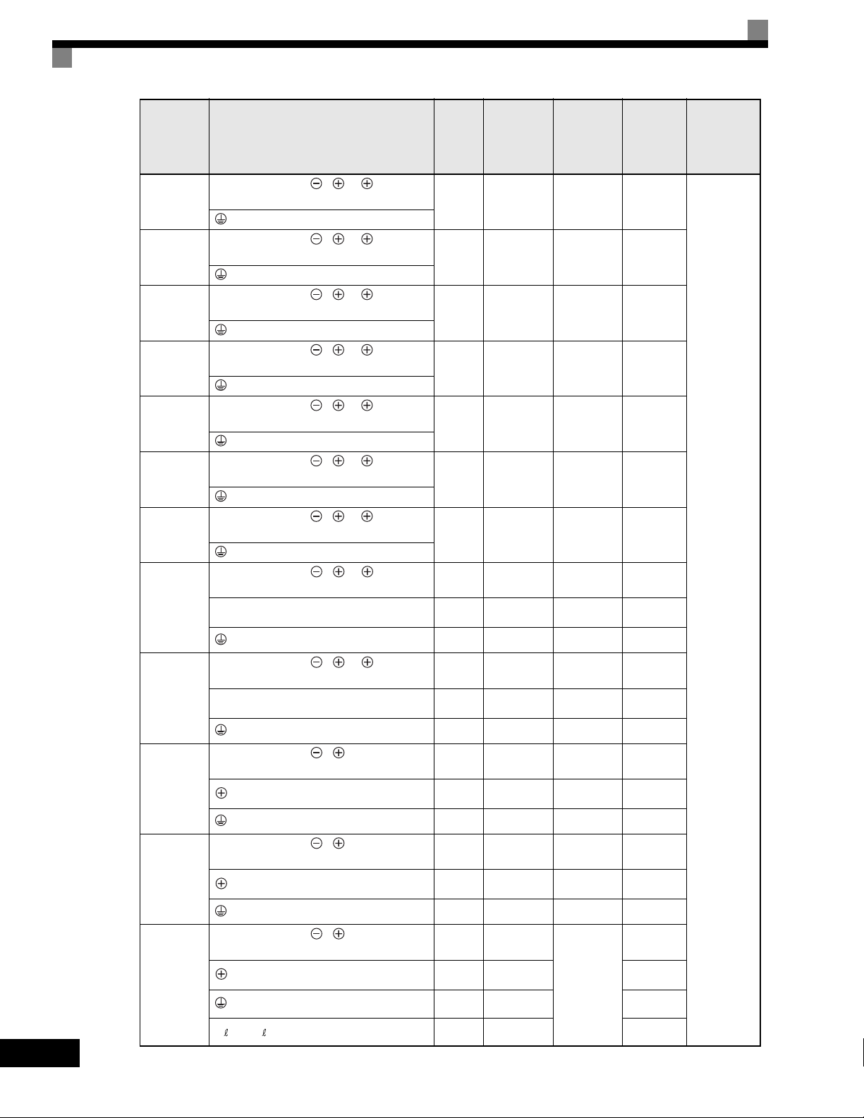
Drive Model
CIMR-
G7U20P4
Table 2.1 200-240 V Class Wire Sizes
Terminal Symbol
R/L1, S/L2, T/L3, , 1, 2, B1, B2,
U/T1, V/T2, W/T3
Te rm i na l
Screws
M4
Clamping
Torque
lb•in(N•m)
10.6 to 13.2
(1.2 to 1.5)
Terminal
Block
Acceptable
Wire Range
AWG(mm
18 to 10
(0.82 to 5.5)
Recommended
2
)
Wire Size
AWG
2
(mm
14
(2)
Wire Type
)
2-6
G7U20P7
G7U21P5
G7U22P2
G7U23P7
G7U25P5
G7U27P5
G7U2011
G7U2015
G7U2018
G7U2022
G7U2030
R/L1, S/L2, T/L3, , 1, 2, B1, B2,
U/T1, V/T2, W/T3
R/L1, S/L2, T/L3, , 1, 2, B1, B2,
U/T1, V/T2, W/T3
R/L1, S/L2, T/L3, , 1, 2, B1, B2,
U/T1, V/T2, W/T3
R/L1, S/L2, T/L3, , 1, 2, B1, B2,
U/T1, V/T2, W/T3
R/L1, S/L2, T/L3, , 1, 2, B1, B2,
U/T1, V/T2, W/T3
R/L1, S/L2, T/L3, , 1, 2, B1, B2,
U/T1, V/T2, W/T3
R/L1, S/L2, T/L3, , 1, 2, U/T1,
V/T2, W/T3
B1, B2
R/L1, S/L2, T/L3, , 1, 2, U/T1,
V/T2, W/T3
B1, B2
R/L1, S/L2, T/L3, , 1, U/T1, V/T2,
W/T3, R1/L11, S1/L21, T1/L31
3
R/L1, S/L2, T/L3, , 1 U/T1,
V/T2, W/T3, R1/L11, S1/L21, T1/L31
3
R/L1, S/L2, T/L3, , 1 U/T1,
V/T2, W/T3, R1/L11, S1/L21, T1/L31
3
r/ 1, / 2
M4
M4
M4
M4
M5
M5
M6
M5
M6
M8
M5
M6
M8
M6
M8
M8
M6
M8
M10
M8
M10
M4
10.6 to 13.2
(1.2 to 1.5)
10.6 to 13.2
(1.2 to 1.5)
10.6 to 13.2
(1.2 to 1.5)
10.6 to 13.2
(1.2 to 1.5)
20.4 to 22.1
(2.3 to 2.5)
20.4 to 22.1
(2.3 to 2.5)
35.2 to 44
(4.0 to 5.0)
20.4 to 22.1
(2.3 to 2.5)
35.2 to 44
(4.0 to 5.0)
79.2 to 88
(9.0 to 10.0)
20.4 to 22.1
(2.3 to 2.5)
35.2 to 44
(4.0 to 5.0)
79.2 to 88
(9.0 to 10.0)
35.2 to 44
(4.0 to 5.0)
79.2 to 88
(9.0 to 10.0)
79.2 to 88
(9.0 to 10.0)
35.2 to 44
(4.0 to 5.0)
79.2 to 88
(9.0 to 10.0)
155 to 198
(17.6 to 22.5)
78 to 95
(8.8 to 10.8)
155 to 198
(17.6 to 22.5)
11.4 to 12.3
(1.3 to 1.4)
18 to 10
(0.82 to 5.5)
18 to 10
(0.82 to 5.5)
18 to 10
(0.82 to 5.5)
18 to 10
(0.82 to 5.5)
10 to 6
(5.5 to 14)
10 to 6
(5.5 to 14)
8 to 1
(8 to 50)
12 to 6
(3.5 to 14)
*3 *3
8 to 1
(8 to 50)
12 to 6
(3.5 to 14)
*3 *3
8 to 1/0
(8 to 60)
8 to 22
(8 to 4)
*3 *3
8 to 1/0
(50 to 60)
8 to 22
(8 to 4)
*3 *3
N/A
14
(2)
14
(2)
12
(3.5)
10
(5.5)
8
(8)
6
(14)
4
(22)
Application
Dependent
3
(30)
Application
Dependent
3
(30)
Application
Dependent
1
(50)
Application
Dependent
2/0
(60)
Application
Dependent
2
(30)
16
(1.25)
Power cables,
e.g., 600 V
vinyl power
cables
Page 38
Wiring Main Circuit Terminals
Drive Model
CIMR-
Terminal Symbol
R/L1, S/L2, T/L3, , 1 U/T1,
V/T2, W/T3, R1/L11, S1/L21, T1/L31
G7U2037
3
r/ 1, / 2
R/L1, S/L2, T/L3, , 1, U/T1, V/T2,
W/T3, R1/L11, S1/L21, T1/L31
G7U2045
3
r/ 1, / 2
, 1
R/L1, S/L2, T/L3, U/T1, V/T2, W/T3,
R1/L11, S1/L21, T1/L31
G7U2055
3
r/ 1, / 2
R/L1, S/L2, T/L3, , 1
U/T1, V/T2, W/T3, R1/L11, S1/L21,
T1/L31
G7U2075
3
r/ 1, / 2
R/L1, S/L2, T/L3, , 1
U/T1, V/T2, W/T3, R1/L11, S1/L21,
G7U2090
T1/L31
3
r/ 1, / 2
R/L1, S/L2, T/L3, , 1
U/T1, V/T2, W/T3, R1/L11, S1/L21, T1/
G7U2110
L31
3
r/ 1, / 2
* The wire thickness is set for copper wires at 75°C
Terminal
Screws
M10
M8
M10
M4
M10
M8
M10
M4
M12
M10
M8
M12
M4
M12
M12
M8
M12
M4
M12
M12
M8
M12
M4
M12
M12
M8
M12
M4
Clamping
Torque
lb•in(N•m)
155 to 198
(17.6 to 22.5)
78 to 95
(8.8 to 10.8)
155 to 198
(17.6 to 22.5)
11.4 to 12.3
(1.3 to 1.4)
155 to 198
(17.6 to 22.5)
78 to 95
(8.8 to 10.8)
155 to 198
(17.6 to 22.5)
11.4 to 12.3
(1.3 to 1.4)
276 to 345
(31.4 to 39.2)
155 to 198
(17.6 to 22.5)
78 to 95
(8.8 to 10.8)
155 to 198
(17.6 to 22.5)
11.4 to 12.3
(1.3 to 1.4)
276 to 345
(31.4 to 39.2)
276 to 345
(31.4 to 39.2)
78 to 95
(8.8 to 10.8)
276 to 345
(31.4 to 39.2)
11.4 to 12.3
(1.3 to 1.4)
276 to 345
(31.4 to 39.2)
276 to 345
(31.4 to 39.2)
78 to 95
(8.8 to 10.8)
276 to 345
(31.4 to 39.2)
11.4 to 12.3
(1.3 to 1.4)
276 to 345
(31.4 to 39.2)
276 to 345
(31.4 to 39.2)
78 to 95
(8.8 to 10.8)
276 to 345
(31.4 to 39.2)
11.4 to 12.3
(1.3 to 1.4)
Terminal
Block
Acceptable
Wire Range
AWG(mm
N/A
N/A
N/A
N/A
Recommended
2
)
Application
Dependent
Application
Dependent
Application
Dependent
(150 × 2P)
(100 × 2P)
Application
Dependent
350 × 2P, or
(200 × 2P, or
300 × 2P, or
(150 × 2P, or
Application
Dependent
(150 × 2P)
350 × 2P, or
(200 × 2P, or
300 × 2P, or
(150 × 2P, or
Application
Dependent
(150 × 2P)
Wire Size
AWG
2
(mm
3/0
(80)
1
(38)
16
(1.25)
1/0 × 2P
(50 × 2P)
1/0
(50)
16
(1.25)
3/0 × 2P
(80 × 2P)
3/0 × 2P
(80 × 2P)
2/0
(80)
16
(1.25)
250 × 2P
4/0 × 2P
2/0 × 2P
(60 × 2P)
16
(1.25)
1/0 × 4P
50 × 4P)
1/0 × 4P
50 × 4P)
300 × 2P
16
(1.25)
1/0 × 4P
50 × 4P)
1/0 × 4P
50 × 4P)
300 × 2P
16
(1.25)
Wire Type
)
Power cables,
e.g., 600 V
vinyl power
cables
2-7
Page 39

Drive Model
CIMR-
G7U40P4
Table 2.2 380-480 V Class Wire Sizes
Terminal Symbol
R/L1, S/L2, T/L3, , 1, 2, B1, B2,
U/T1, V/T2, W/T3
Te rm i na l
Screws
M4
Tightening
To rq u e
(N•m)
10.6 to 13.2
(1.2 to 1.5)
Possible Wire
Sizes
2
(AWG)
mm
18 to 10
(0.82 to 5.5)
Recommended
Wire Size
2
(AWG)
mm
14
(2)
Wire Type
G7U40P7
G7U41P5
G7U42P2
G7U43P7
G7U44P0
G7U45P5
G7U47P5
R/L1, S/L2, T/L3, , 1, 2, B1, B2,
U/T1, V/T2, W/T3
R/L1, S/L2, T/L3, , 1, 2, B1, B2,
U/T1, V/T2, W/T3
R/L1, S/L2, T/L3, , 1, 2, B1, B2,
U/T1, V/T2, W/T3
R/L1, S/L2, T/L3, , 1, 2, B1, B2,
U/T1, V/T2, W/T3
R/L1, S/L2, T/L3, , 1, 2, B1, B2,
U/T1, V/T2, W/T3
R/L1, S/L2, T/L3, , 1, 2, B1, B2,
U/T1, V/T2, W/T3
R/L1, S/L2, T/L3, , 1, 2, B1, B2,
U/T1, V/T2, W/T3
M4
M4
M4
M4
M4
M4
M5
10.6 to 13.2
(1.2 to 1.5)
10.6 to 13.2
(1.2 to 1.5)
10.6 to 13.2
(1.2 to 1.5)
10.6 to 13.2
(1.2 to 1.5)
10.6 to 13.2
(1.2 to 1.5)
10.6 to 13.2
(1.2 to 1.5)
20.4 to 22.1
(2.3 to 2.5)
18 to 10
(0.82 to 5.5)
18 to 10
(0.82 to 5.5)
18 to 10
(0.82 to 5.5)
18 to 10
(0.82 to 5.5)
18 to 10
(0.82 to 5.5)
10 to 6
(5.5 to 14)
10 to 6
(5.5 to 14)
14
(2)
14
(2)
12
(3.5)
14
(2)
12
(3.5)
12
(3.5)
10
(5.5)
8
(8)
Power cables,
e.g., 600 V
vinyl power
cables
G7U4011
G7U4015
G7U4018
G7U4022
R/L1, S/L2, T/L3, , 1, 2, B1, B2,
U/T1, V/T2, W/T3
R/L1, S/L2, T/L3, , 1, 2, U/T1,
V/T2, W/T3
B1, B2
R/L1, S/L2, T/L3, , 1, 3, U/T1,
V/T2, W/T3, R1/L11, S1/L21, T1/L31
R/L1, S/L2, T/L3, , 1, 3, U/T1,
V/T2, W/T3, R1/L11, S1/L21, T1/L31
M5
M5
(M6)
M5
M5
M5
(M6)
M6
M8
M6
M8
20.4 to 22.1
(2.3 to 2.5)
20.4 to 22.1
(2.3 to 2.5)
35.2 to 44
(4.0 to 5.0)
35.2 to 44
(4.0 to 5.0)
20.4 to 22.1
(2.3 to 2.5)
35.2 to 44
(4.0 to 5.0)
35.2 to 44
(4.0 to 5.0)
79.2 to 88
(9.0 to 10.0)
35.2 to 44
(4.0 to 5.0)
79.2 to 88
(9.0 to 10.0)
10 to 6
(5.5 to 14)
10 to 6
(5.5 to 14)
10 to 6
(5.5 to 14)
10 to 6
(5.5 to 14)
10 to 6
(5.5 to 14)
12 to 3
(3.5 to 30)
*3 *3
12 to 3
(3.5 to 30)
*3 *3
8
(8)
10
(5.5)
8
(8)
8
(8)
8
(8)
6
(14)
4
(22)
2-8
Page 40
Wiring Main Circuit Terminals
Drive Model
CIMR-
G7U4030
G7U4037
G7U4045
G7U4055
G7U4075
G7U4090
G7U4110
G7U4132
Terminal Symbol
R/L1, S/L2, T/L3, , 1, U/T1, V/T2,
W/T3, R1/L11, S1/L21, T1/L31
3
R/L1, S/L2, T/L3, , 1, U/T1, V/T2,
W/T3, R1/L11, S1/L21, T1/L31
R/L1, S/L2, T/L3, , 1, U/T1, V/T2,
W/T3, R1/L11, S1/L21, T1/L31
3
R/L1, S/L2, T/L3, , 1, U/T1, V/T2,
W/T3, R1/L11, S1/L21, T1/L31
3
r/ 1, 200/2200, 400/2400
R/L1, S/L2, T/L3, , 1, U/T1, V/T2,
W/T3, R1/L11, S1/L21, T1/L31
3
r/ 1, 200/2200, 400/2400
R/L1, S/L2, T/L3, , 1, U/T1, V/T2,
W/T3, R1/L11, S1/L21, T1/L33
3
r/ 1, 200/2200, 400/2400
R/L1, S/L2, T/L3, , 1, U/T1, V/T2,
W/T3, R1/L11, S1/L21, T1/L33
3
r/ 1, 200/2200, 400/2400
R/L1, S/L2, T/L3, , 1, U/T1, V/T2,
W/T3, R1/L11, S1/L21, T1/L31
3
r/ 1, 200/2200, 400/2400
Ter m in al
Screws
M8
M6
M8
M8
M8
M6
M8
M10
M8
M10
M4
M10
M8
M10
M4
M10
M8
M12
M4
M10
M8
M12
M4
M12
M8
M12
M4
Tightening
To rq u e
(N•m)
79.2 to 88
(9.0 to 10.0)
35.2 to 44
(4.0 to 5.0)
79.2 to 88
(9.0 to 10.0)
79.2 to 88
(9.0 to 10.0)
79.2 to 88
(9.0 to 10.0)
35.2 to 44
(4.0 to 5.0)
79.2 to 88
(9.0 to 10.0)
154.8 to 197.5
(17.6 to 22.5)
78 to 95
(8.8 to 10.8)
154.8 to 197.5
(17.6 to 22.5)
11.4 to 12.3
(1.3 to 1.4)
154.8 to 197.5
(17.6 to 22.5)
78 to 95
(8.8 to 10.8)
154.8 to 197.5
(17.6 to 22.5)
11.4 to 12.3
(1.3 to 1.4)
154.8 to 197.5
(17.6 to 22.5)
78 to 95
(8.8 to 10.8)
154.8 to 197.5
(17.6 to 22.5)
11.4 to 12.3
(1.3 to 1.4)
154.8 to 197.5
(17.6 to 22.5)
78 to 95
(8.8 to 10.8)
154.8 to 197.5
(17.6 to 22.5)
11.4 to 12.3
(1.3 to 1.4)
276 to 345
(31.4 to 39.2)
78 to 95
(8.8 to 10.8)
276 to 345
(31.4 to 39.2)
11.4 to 12.3
(1.3 to 1.4)
Possible Wire
Sizes
2
(AWG)
mm
8 to 1/0
(8 to 60)
(8 to 4)
8 to 22
*3 *3
2 to 1/0
(30 to 60)
8 to 1/0
(8 to 60)
8 to 4
(8 to 22)
*3 *3
N/A
Recommended
Wire Size
2
(AWG)
mm
2
(38)
Application
Dependent
2
(38)
1
(50)
Application
Dependent
1/0
(50)
Application
Dependent
2
(38)
16
(1.25)
4/0
(100)
Application
Dependent
1
(50)
16
(1.25)
1/0 × 2P
(50 × 2P)
Application
Dependent
2/0
(60)
16
(1.25)
3/0 × 2P
(80 × 2P)
Application
Dependent
4/0
(100)
16
(1.25)
3/0 × 2P
(80 × 2P)
Application
Dependent
1/0 × 2P
(50 × 2P)
16
(1.25)
Wire Type
Power cables,
e.g., 600 V
vinyl power
cables
2-9
Page 41

Drive Model
CIMR-
G7U4160
Ter m i n a l S y m b ol
R/L1, S/L2, T/L3, , 1, U/T1, V/T2,
W/T3, R1/L11, S1/L21, T1/L31
3
r/ 1, 200/2200, 400/2400
Terminal
Screws
M12
M8
M12
M4
Tightening
To rq u e
(N•m)
276 to 345
(31.4 to 39.2)
78 to 95
(8.8 to 10.8)
276 to 345
(31.4 to 39.2)
11.4 to 12.3
(1.3 to 1.4)
Possible Wire
Sizes
2
(AWG)
mm
R/L1, S/L2, T/L3, R1/L11, S1/L21, T1/
L31
U/T1, V/T2, W/T3
694 to 867
(78.4 to 98.0)
G7U4185
, 1
M16
3
r/ 1, 200/2200, 400/2400
M4
11.4 to 12.3
(1.3 to 1.4)
R/L1, S/L2, T/L3, R1/L11, S1/L21, T1/
L31
N/A
U/T1, V/T2, W/T3
694 to 867
(78.4 to 98.0)
G7U4220
, 1
M16
3
r/ 1, 200/2200, 400/2400
M4
11.4 to 12.3
(1.3 to 1.4)
R/L1, S/L2, T/L3, R1/L11, S1/L21, T1/
L31
U/T1, V/T2, W/T3
694 to 867
(78.4 to 98.0)
G7U4300
, 1
M16
3
r/ 1, 200/2200, 400/2400
* The wire thickness is set for copper wires at 75°C.
1
Wire size range provided for Drives using insulated screw-type terminal blocks with a single conductor. Refer to applicable codes for proper wire type and size.
*
2
Recommended wire sizes are based on the Drive current ratings and NEC Article 310 Table 310.16, 75 Degree Celsius copper or equivalent.
*
3
*
Uses non-insulated screw-type terminals. Refer to applicable codes for proper wire type and size.
M4
11.4 to 12.3
(1.3 to 1.4)
Recommended
Wire Size
2
(AWG)
mm
4/0 × 2P
(100 × 2P)
Application
Dependent
1/0 × 2P
(50 × 2P)
16
(1.25)
250 x 2P
(125 x 2P)
250 x 2P
(125 x 2P)
600 x 2P
(325 x 2P)
Application
Dependent
3/0 x 2P
(80 x 2P)
16
(1.25)
350 x 2P
(185 x 2P)
300 x 2P
(150 x 2P)
250 x 4P
(125 x 4P)
Application
Dependent
4/0 x 2P
(100 x 2P)
16
(1.25)
600 x 2P
(325 x 2P)
500 x 2P
(300 x 2P)
400 x 4P
(200 x 4P)
Application
Dependent
250 x 2P
(125 x 2P)
16
(1.25)
Wire Type
Power cables,
e.g., 600 V
vinyl power
cables
2-10
IMPORTANT
Determine the wire size for the main circuit so that line voltage drop is within 2% of the rated voltage. Line
voltage drop is calculated as follows:
Line voltage drop (V) = x wire resistance (Ω/km) x wire length (m) x current (A) x 10
3
-3
Page 42

Wiring Main Circuit Terminals
Table 2.3 Closed-loop Connector Sizes (JIS C2805) (200-240 V Class and 380-480 V Class)
Wire Size * Terminal Screw
AWG mm
20 0.5
18 0.75
16 1.25
14 2
12 / 10 3.5 / 5.5
88
614
422
3 / 2 30 / 38
1 / 1/0 50 / 60
2/0 70
3/0 80
2
Ring Tongue (R-Type) Closed-Loop Connectors (Lugs)
JST Corporation Part Numbers **
M3.5 1.25 - 3.7
M4 1.25 - 4
M3.5 1.25 - 3.7
M4 1.25 - 4
M3.5 1.25 - 3.7
M4 1.25 - 4
M3.5 2 - 3.7
M4 2 - 4
M5 2 - 5
M6 2 - 6
M8 2 - 8
M4 5.5 - 4
M5 5.5 - 5
M6 5.5 - 6
M8 5.5 - 8
M5 8 - 5
M6 8 - 6
M8 8 - 8
M5 14 - 5
M6 14 - 6
M8 14 - 8
M5 22 - 5
M6 22 - 6
M8 22 - 8
M6 38 - 6
M8 38 - 8
M8 60 - 8
M10 60 - 10
M8 70 - 8
M10 70 - 10
M10 80 - 10
M16 80 - 16
2-11
Page 43

T
Wire Size * Terminal Screw
4/0 100
250 / 300MCM 125 / 150
400MCM 200 M12 200 - 12
650MCM 325
* Wire sizes are based on 75 degrees Celsius copper wire.
** Equivalent connector can be used.
Determine the wire size for the main circuit so that line voltage drop is within 2% of the rated voltage. Line
voltage drop is calculated as follows:
x wire resistance (W/km) x wire length (m) x current (A) x 10
IMPORTAN
Line voltage drop (V) =
3
Ring Tongue (R-Type) Closed-Loop Connectors (Lugs)
JST Corporation Part Numbers **
M10 100 - 10
M12 100 - 12
M16 100 - 16
M10 150 - 10
M12 150 - 12
M16 150 - 16
M12 x 2 325 - 12
M16 325 - 16
-3
2-12
Page 44

Wiring Main Circuit Terminals
Main Circuit Terminal Functions
Main circuit terminal functions are summarized according to terminal symbols in Table 2.4. Wire the terminals
correctly for the desired purposes.
Table 2.4 Main Circuit Terminal Functions (200-240 V Class and 380-480 V Class)
Purpose Ter m in al Sy mb ol
R/L1, S/L2, T/L3 20P4 to 2110 40P4 to 4300
Main circuit power input
R1/L11, S1/L21, T1/L31 2018 to 2110 4018 to 4300
Drive outputs U/T1, V/T2, W/T3 20P4 to 2110 40P4 to 4300
208-240 Vac 480 Vac
Model: CIMR-G7U
DC power input
Braking Resistor Unit connection
DC link choke connection
Braking Transistor Unit connection
Ground 20P4 to 2110 40P4 to 4300
1,
B1, B2 20P4 to 27P5 40P4 to 4015
1, 2
3,
20P4 to 2110 40P4 to 4300
20P4 to 2015 40P4 to 4015
2018 to 2110 4018 to 4300
2-13
Page 45

Main Circuit Configurations
The main circuit configurations of the Drive are shown in Tabl e 2 .5 .
Table 2.5 Drive Main Circuit Configurations
208-240 Vac 480 Vac
CIMR-G7U20P4 to 2015
1
+
+
2
R/L1
S/L2
T/L3
−
CIMR-G7U2018, 2022
+
1
R/L1
S/L2
T/L3
R1/L11
S1/L21
T1/L31
−
Power
supply
+
Power
supply
CIMR-G7U40P4 to 4015
Power
supply
B1 B2
Control
circuits
U/T1
V/T2
W/T3
B1 B2
Control
circuits
U/T1
V/T2
W/T3
+
+
R/L1
S/L2
T/L3
−
1
2
CIMR-G7U4018 to 4045
+
3
+
1
R/L1
S/L2
T/L3
R1/L11
S1/L21
T1/L31
−
Control
circuits
U/T1
V/T2
W/T3
3
Power
supply
Control
circuits
U/T1
V/T2
W/T3
2-14
CIMR-G7U2030 to 2110
+
3
+
1
R/L1
S/L2
T/L3
R1/L11
S1/L21
T1/L31
−
r/
l
1
/l2
Power
supply
Control
circuits
Note Consult your Yaskawa representative before using 12-phase rectification.
U/T1
V/T2
W/T3
200/
400/
CIMR-G7U4055 to 4300
+
1
R/L1
S/L2
T/L3
R1/L11
S1/L21
T1/L31
−
r/
l
1
l
2
200
l
2
400
+
3
Power
supply
Control
circuits
U/T1
V/T2
W/T3
Page 46

Wiring Main Circuit Terminals
Standard Connection Diagrams
Standard Drive connection diagrams are shown in Fig 2.4. These are the same for both 208-240 Vac and 480
Vac Drives. The connections depend on the Drive capacity.
CIMR-G7U20P4 to 2015 and 40P4 to
CIMR-G7U2018, 2022, and 4018 to 4045
4015
2B1 B2
U/T1
V/T2
W/T3
Braking Resistor
Unit (optional)
IM
3-phase 200-240
Vac(380-480 Vac)
The DC link choke is built in.
R/L1
S/L2
T/L3
R1/L11
S1/L21
T1/L31
DC link choke
(optional)
+
+
−
1
R/L1
S/L2
3-phase 200-240Vac
(380-480 Vac)
T/L3
Be sure to remove the short-circuit bar before connecting the DC
link choke.
CIMR-G7U2030 to 2110 CIMR-G7U4055 to 4300
Braking Resistor
Unit (optional)
Braking Unit
(optional)
+
+
3
−
U/T1
V/T2
W/T3
R/L1
IM
3-phase 380-480 Vac
S/L2
T/L3
R1/L11
S1/L21
T1/L31
r/l1
3-phase
200-240Vac
1
R/L1
S/L2
T/L3
R1/L11
S1/L21
T1/L31
r/l1
/l2
+
1
+
1
200/
400/
2200
l
l
2400
+
3
+
3
Braking Resistor
Unit (optional)
Braking Unit
(optional)
−
U/T1
V/T2
W/T3
Braking Resistor
Unit (optional)
Braking Unit
(optional)
−
U/T1
V/T2
W/T3
IM
IM
Control power is supplied internally from the main circuit DC power supply for all Drive models.
Fig 2.4 Main Circuit Terminal Connections
2-15
Page 47

Wiring the Main Circuits
This section describes wiring connections for the main circuit inputs and outputs.
Wiring Main Circuit Inputs
Observe the following precautions for the main circuit power supply input.
Installing a Molded-case Circuit Breaker
Always connect the power input terminals (R/L1, S/L2, and T/L3) and power supply via a molded-case circuit
breaker (MCCB) suitable for the Drive.
• Choose an MCCB with a capacity of 1.5 to 2 times the Drive's rated current.
• For the MCCB's time characteristics, be sure to consider the Drive's overload protection (one minute at
150% of the rated output current).
• If the same MCCB is to be used for more than one Drive, or other devices, set up a sequence so that the
power supply will be turned OFF by a fault output, as shown in Fig 2.5.
Power
supply
20P4 to 2030: 3-phase,
200 to 240 Vac, 50/60 Hz
2037 to 2110: 3-phase,
200 to 230 Vac, 50/60 Hz
40P4 to 4300: 3-phase,
380 to 460 Vac, 50/60 Hz
* For 380-480 V class Drives, connect a 460/230 V transformer.
Fig 2.5 MCCB Installation
Drive
R/L1
S/L2
T/L3
Fault output
(NC)
Installing a Ground Fault Interrupter
Drive outputs use high-speed switching, so high-frequency leakage current is generated. Therefore, at the
Drive primary side, use a ground fault interrupter to detect only the leakage current in the frequency range that
is hazardous to humans and exclude high-frequency leakage current.
• For the special-purpose ground fault interrupter for Drives, choose a ground fault interrupter with a
sensitivity amperage of at least 30 mA per Drive.
• When using a general ground fault interrupter, choose a ground fault interrupter with a sensitivity
amperage of 200 mA or more per Drive and with an operating time of 0.1 s or more.
2-16
Page 48

Wiring Main Circuit Terminals
Installing a Magnetic Contactor
If the power supply for the main circuit is to be shut off during a sequence, a magnetic contactor can be used.
When a magnetic contactor is installed on the primary side of the main circuit to forcibly stop the Drive,
however, the regenerative braking does not work and the Drive will coast to a stop.
• The Drive can be started and stopped by opening and closing the magnetic contactor on the primary side.
Frequently opening and closing the magnetic contactor, however, may cause the Drive to break down. Start
and stop the Drive at most once every 30 minutes.
• When the Drive is operated with the Digital Operator, automatic operation cannot be performed after
recovery from a power interruption.
• If the Braking Resistor Unit is used, program the sequence so that the magnetic contactor is turned OFF by
the contact of the Unit's thermal overload relay.
Connecting Input Power Supply to the Terminal Block
Input power supply can be connected to any terminal R/L1, S/L2, or T/L3 on the terminal block; the phase
sequence of input power supply is irrelevant to the phase sequence.
Installing an AC Reactor
If the Drive is connected to a large-capacity power transformer (600 kVa or more) or the phase advancing
capacitor is switched, an excessive peak current may flow through the input power circuit, causing the
converter unit to break down.
To prevent this, install an optional AC Reactor on the input side of the Drive or a DC link choke to the DC link
choke connection terminals.
This also improves the power factor on the power supply side.
Installing a Surge Absorber
Always use a surge absorber or diode for inductive loads near the Drive. These inductive loads include
magnetic contactors, electromagnetic relays, solenoid valves, solenoids, and magnetic brakes.
Installing a Noise Filter on Power Supply Side
Install a noise filter to eliminate noise transmitted between the power line and the Drive.
• Correct Noise Filter Installation
Power
supply
MCCB
Noise
filter
Drive
IM
MCCB
Fig 2.6 Correct Power supply Noise Filter Installation
Other
controllers
Use a special-purpose noise filter for Drives.
2-17
Page 49
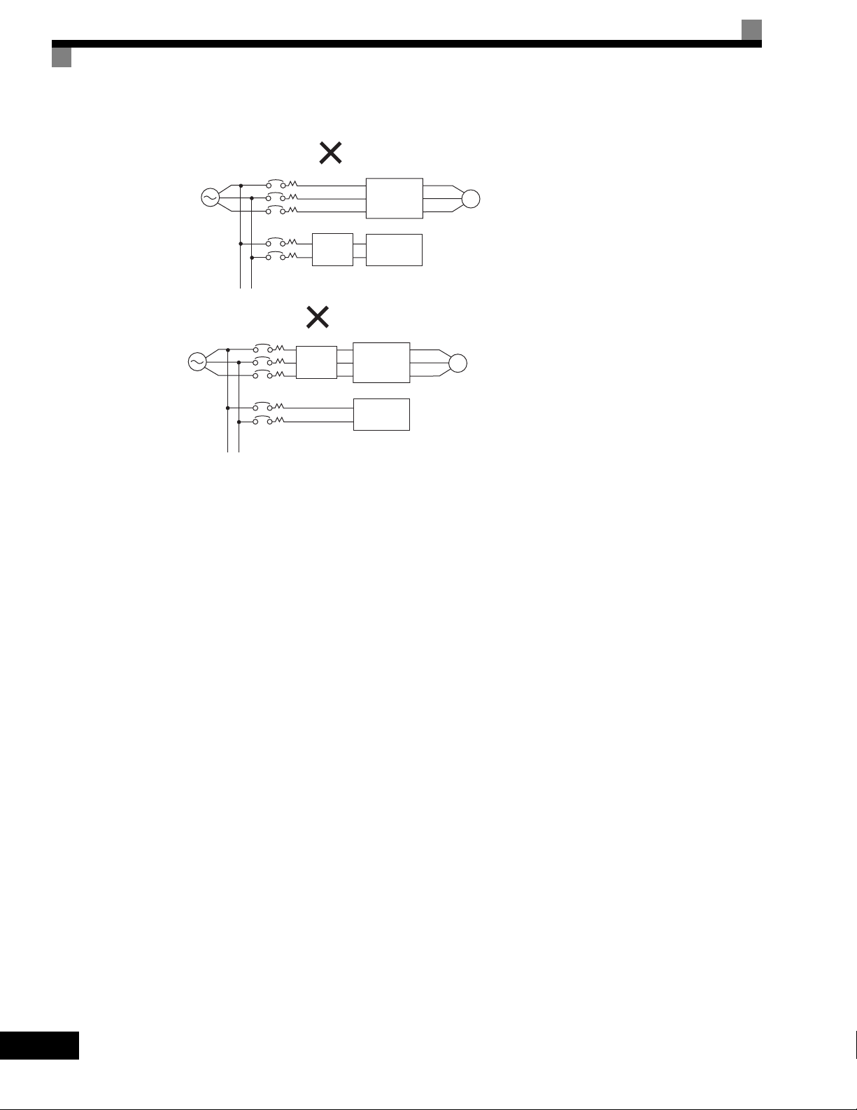
• Incorrect Noise Filter Installation
Power
supply
MCCB
Power
supply
MCCB
MCCB
MCCB
Generalpurpose
noise filter
Generalpurpose
noise filter
Drive
Other
controllers
Drive
Other
controllers
IM
IM
Do not use general-purpose noise filters. Generalpurpose noise filter can not effectively suppress
noise generated from the Drive.
Fig 2.7 Incorrect Power supply Noise Filter Installation
Wiring the Output Side of Main Circuit
Observe the following precautions when wiring the main output circuits.
Connecting the Drive and Motor
Connect output terminals U/T1, V/T2, and W/T3 to motor lead wires U/T1, V/T2, and W/T3, respectively.
Check that the motor rotates forward with the forward run command. Switch over any two of the output
terminals to each other and reconnect if the motor rotates in reverse with the forward run command.
Never Connect a Power Supply to Output Terminals
Never connect a power supply to output terminals U/T1, V/T2, and W/T3. If voltage is applied to the output
terminals, the internal circuits of the Drive will be damaged.
Never Short or Ground Output Terminals
If the output terminals are touched with bare hands or the output wires come into contact with the Drive
casing, an electric shock or grounding will occur. This is extremely hazardous. Do not short the output wires.
Do Not Use a Phase Advancing Capacitor or Noise Filter
Never connect a phase advancing capacitor or LC/RC noise filter to an output circuit. The high-frequency
components of the Drive output may result in overheating or damage to these part or may result in damage to
the Drive or cause other parts to burn.
2-18
Page 50
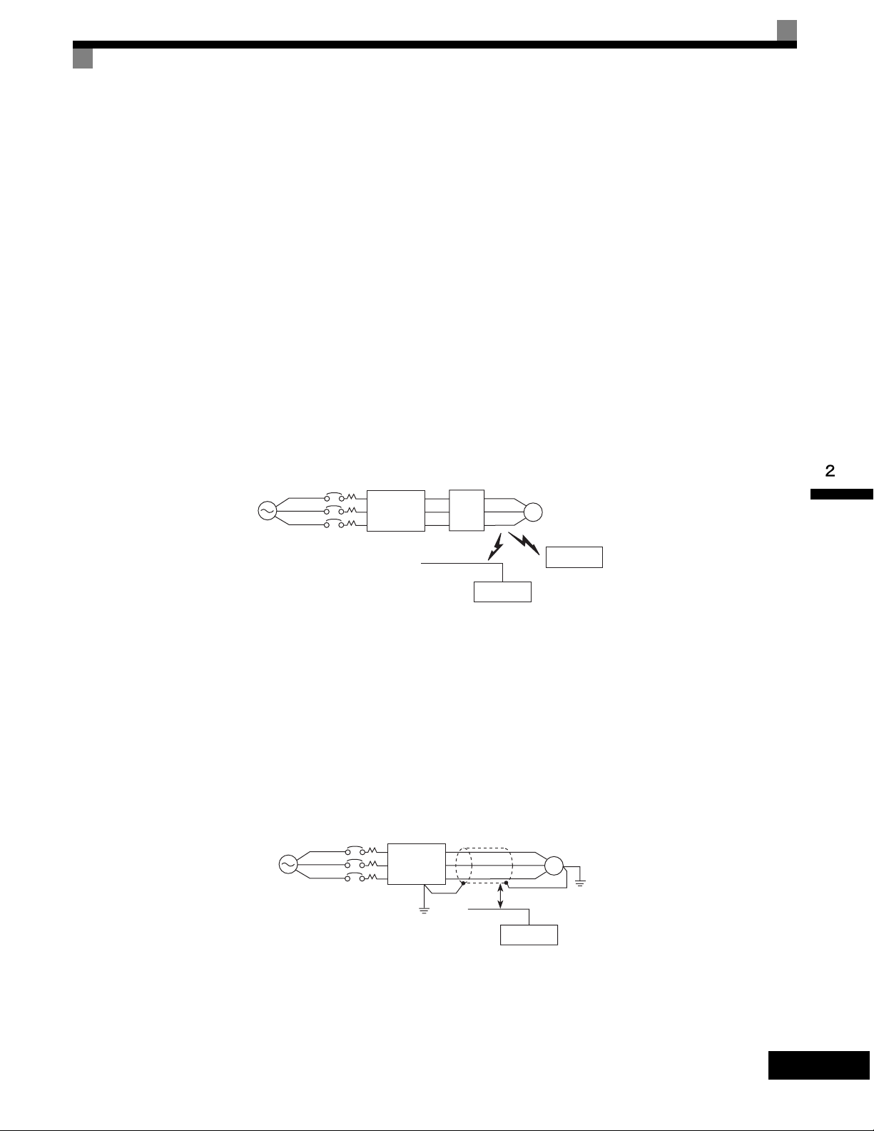
Wiring Main Circuit Terminals
Do Not Use an Electromagnetic Switch
Never connect an electromagnetic switch (MC) between the Drive and motor and turn it ON or OFF during
operation. If the MC is turned ON while the Drive is operating, a large inrush current will be created and the
overcurrent protection in the Drive will operate.
When using an MC to switch to a commercial power supply, stop the Drive and motor before operating the
MC. Use the speed search function if the MC is operated during operation. If measures for momentary power
interrupts are required, use a delayed release MC.
Installing a Thermal Overload Relay
This Drive has an electronic thermal protection function to protect the motor from overheating. If, however,
more than one motor is operated with one Drive or a multi-pole motor is used, always install a thermal relay
(THR) between the Drive and the motor and set L1-01 to 0 (no motor protection). The sequence should be
designed so that the contacts of the thermal overload relay turn OFF the magnetic contactor on the main circuit
inputs.
Installing a Noise Filter on Output Side
Connect a noise filter to the output side of the Drive to reduce radio noise and inductive noise.
Power
supply
Inductive Noise: Electromagnetic induction generates noise on the signal line, causing the controller to malfunction.
Radio Noise: Electromagnetic waves from the Drive and cables cause the broadcasting radio receiver to make noise.
MCCB
Drive
Noise
filter
Signal line
Inductive
noise
Controller
IM
Radio noise
AM radio
Fig 2.8 Installing a Noise Filter on the Output Side
Countermeasures Against Inductive Noise
As described previously, a noise filter can be used to prevent inductive noise from being generated on the
output side. Alternatively, cables can be routed through a grounded metal pipe to prevent inductive noise.
Keeping the metal pipe at least 30 cm (approximately 1 foot) away from the signal line considerably reduces
inductive noise.
Power
supply
MCCB
Drive
Metal pipe
IM
30 cm min.
Signal line
(1 ft.)
Controller
Fig 2.9 Countermeasures Against Inductive Noise
2-19
Page 51
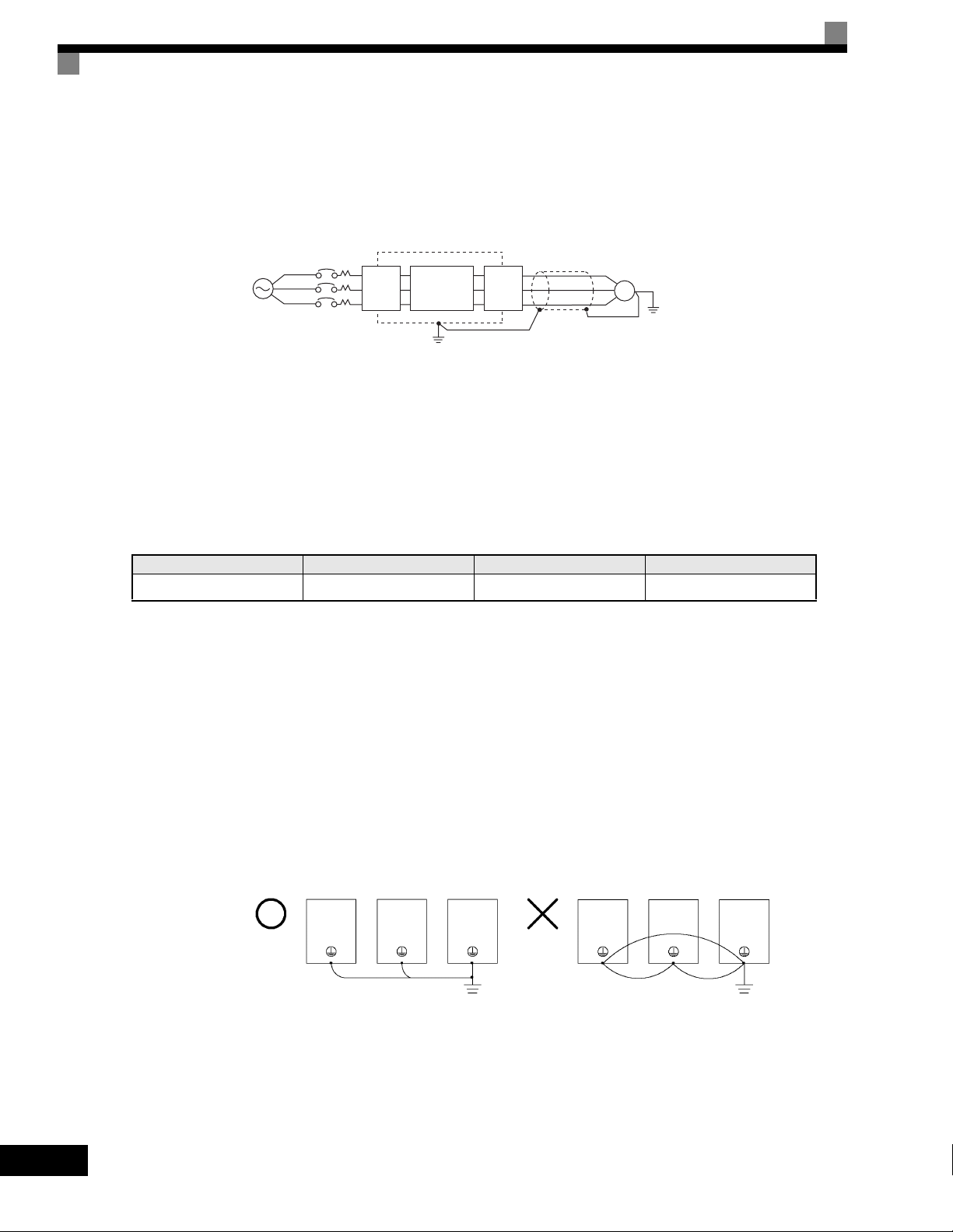
Countermeasures Against Radio Interference
Radio noise is generated from the Drive as well as from the input and output lines. To reduce radio noise,
install noise filters on both input and output sides, and also install the Drive in a totally enclosed steel box.
The cable between the Drive and the motor should be as short as possible.
Noise
filter
Steel box
Drive
Noise
filter
Metal pipe
IM
Power
supply
MCCB
Fig 2.10 Countermeasures Against Radio Interference
Cable Length between Drive and Motor
If the cable between the Drive and the motor is long, the high-frequency leakage current will increase, causing
the Drive output current to increase as well. This may affect peripheral devices. To prevent this, adjust the
carrier frequency (set in C6-01, C6-02) as shown in Table 2.6. (For details, refer to Chapter 3 User
Parameters.)
Table 2.6 Cable Length between Drive and Motor
Cable length 50 m max. (164 ft) 100 m max. (328 ft) More than 100 m (> 328 ft)
Carrier frequency 15 kHz max. 10 kHz max. 5 kHz max.
Ground Wiring
Observe the following precautions when wiring the ground line.
• Always use the ground terminal of the 200-240 V Drive with a ground resistance of less than 100 Ω and
that of the 380-480 V Drive with a ground resistance of less than 10 Ω.
• Do not share the ground wire with other devices, such as welding machines or power tools.
• Always use a ground wire that complies with technical standards on electrical equipment and minimize the
length of the ground wire.
Leakage current flows through the Drive. Therefore, if the distance between the ground electrode and the
ground terminal is too long, potential on the ground terminal of the Drive will become unstable.
• When using more than one Drive, be careful not to loop the ground wire.
2-20
OK
NO
Fig 2.11 Ground Wiring
Page 52
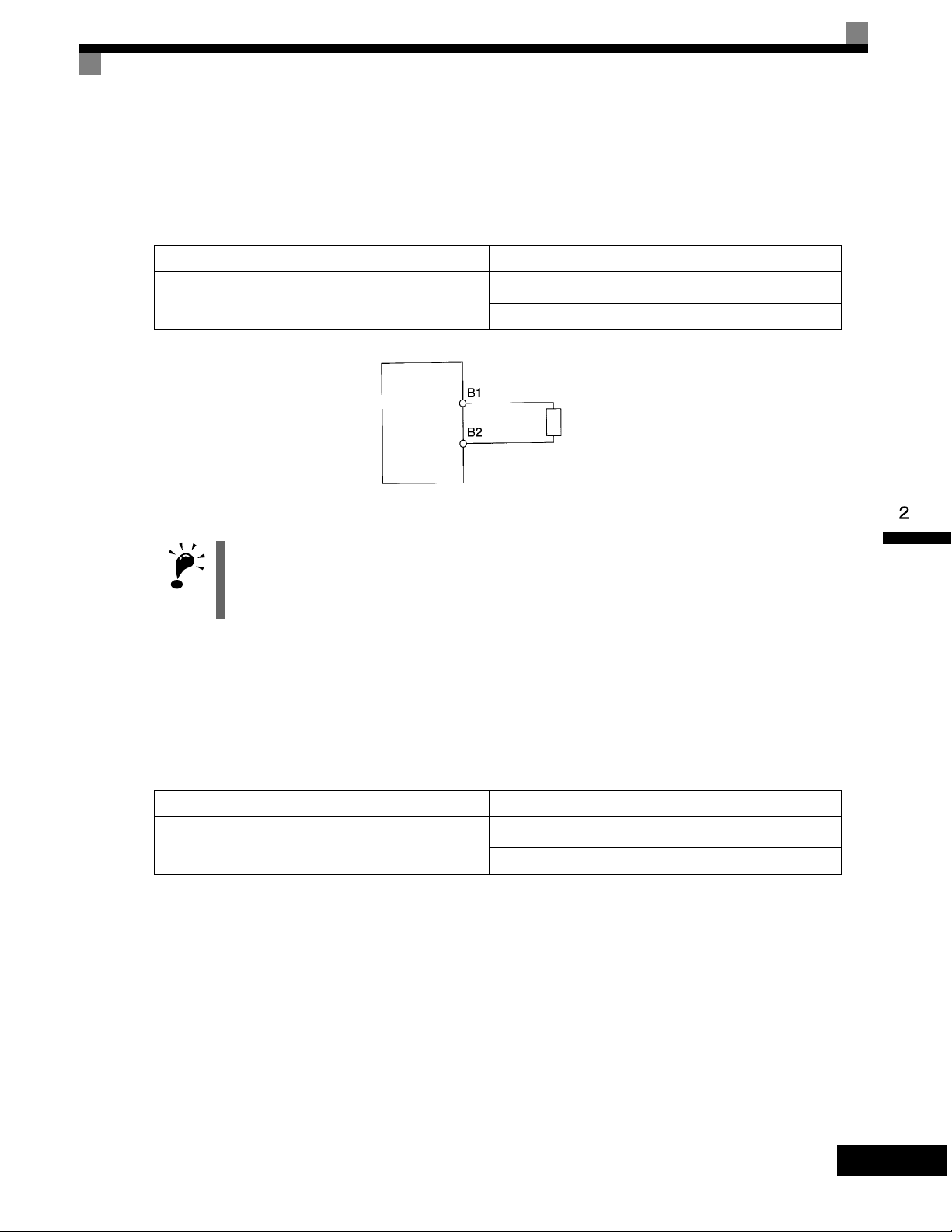
Wiring Main Circuit Terminals
T
Connecting the Braking Resistor (ERF)
A Braking Resistor that mounts to the Drive can be used with 200-240 V and 380-480 V Class Drives with
outputs from 0.4 to 3.7 kW.
Connect the braking resistor as shown in Fig 2.12.
Table 2.7
L8-01 (Protect selection for internal DB resistor) 1 (Enables overheat protection)
L3-04 (Stall prevention selection during deceleration)
(Select either one of them.)
Drive
Fig 2.12 Connecting the Braking Resistor
The braking resistor connection terminals are B1 and B2. Do not connect to any other terminals. Connecting
to any terminals other than B1 or B2 can cause the resistor to overheat, resulting in damage to the
equipment.
IMPORTAN
0 (Disables stall prevention function)
3 (Enables stall prevention function with braking resistor)
Braking resistor
Connecting the Braking Resistor Unit (LKEB) and Braking Unit (CDBR)
Use the following settings when using a Braking Resistor Unit. Refer to User Parameters on page 10-19 for
connection methods for a Braking Resistor Unit.
A Braking Resistor that mounts to the Drive can also be used with Drives with outputs from 0.4 to 3.7 kW.
Table 2.8
L8-01 (Protect selection for internal DB resistor) 0 (Disables overheat protection)
L3-04 (Stall prevention selection during deceleration)
(Select either one of them.)
0 (Disables stall prevention function)
3 (Enables stall prevention function with braking resistor)
L8-01 is used when a braking resistor without thermal overload relay trip contacts (ERF type mounted to
Drive) is connected.
The Braking Resistor Unit cannot be used and the deceleration time cannot be shortened by the Drive if L3-04
is set to 1 (i.e., if stall prevention is enabled for deceleration).
2-21
Page 53

Wiring Control Circuit Terminals
Wire Sizes and Closed-loop Connectors
For remote operation using analog signals, keep the control line length between the Digital Operator or
operation signals and the Drive to 50 m (164 ft) or less, and separate the lines from high-power lines (main
circuits or relay sequence circuits) to reduce induction from peripheral devices.
When setting frequencies from an external frequency reference (and not from a Digital Operator), used
shielded twisted-pair wires and ground the shield to terminal E (G), as shown in the following diagram.
Shield terminal
Speed setting power supply, +15 V 20 mA
2 kΩ
2 kΩ
2 kΩ
2 kΩ
Fig 2.13
Terminal numbers and wire sizes are shown in Tab l e 2. 9.
Table 2.9 Terminal Numbers and Wire Sizes (Same for all Models)
Terminals
FM, AC, AM, M3, M4,
SC, A1, A2, A3, +V, -V,
S1, S2, S3, S4, S5, S6,
S7, S8, MA, MB, MC,
M1, M2, P3, C3, P4, C4,
MP, RP, R+, R-, S9, S10,
S11, S12, S+, S-, IG, SN,
SP
Te rm i na l
Screws
Phoenix
*3
type
Tightening
Torque
lb-in (N•m)
4.2 to 5.3
(0.5 to 0.6)
Possible Wire
Sizes
AWG (mm
Stranded wire:
26 to 16
(0.14 to 1.5)
Master speed reference, -10 to 10 V
Master speed reference, 4 to 20 mA
Auxiliary reference
Pulse input, 32 kHz max.
Analog common
Recommended
Wire Size AWG
2
)
(mm
2
)
18
(0.75)
•Shielded, twisted-pair wire
•Shielded, polyethylene-
covered, vinyl sheath cable
Wire Type
*1
*2
2-22
E (G) M3.5
* 1. Use shielded twisted-pair cables to input an external frequency reference.
* 2. Yaskawa recommends using straight solderless terminals on digital inputs to simplify wiring and improve reliability.
* 3. Yaskawa recommends using a thin-slot screwdriver with a 3.5 mm blade width.
7.0 to 8.8
(0.8 to 1.0)
20 to 14
(0.5 to 2)
12
(1.25)
Page 54
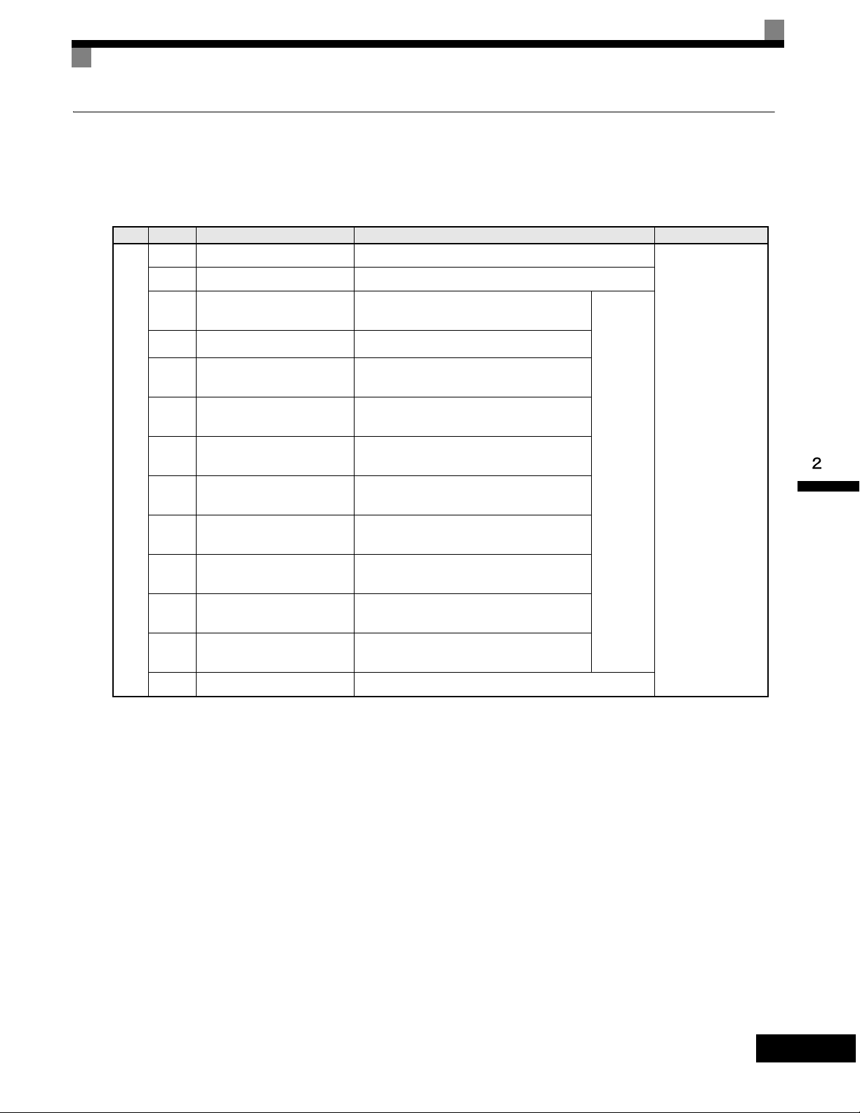
Wiring Control Circuit Terminals
Control Circuit Terminal Functions
The functions of the control circuit terminals are shown in Table 2.10. Use the appropriate terminals for the correct
purposes.
Table 2.10 Control Circuit Terminals
Typ e
No. Signal Name Function Signal Level
S1 Forward run/stop command Forward run when CLOSED; stopped when OPEN.
S2 Reverse run/stop command Reverse run when CLOSED; stopped when OPEN.
Digital
input
signals
S3
S4
S5
S6
S7
S8
S9
S10
S11
S12
Multi-function input 1
Multi-function input 2
Multi-function input 3
Multi-function input 4
Multi-function input 5
Multi-function input 6
Multi-function input 7
Multi-function input 8
Multi-function input 9
Multi-function input 10
*1
*1
*1
*1
*1
*1
*1
*1
*1
*1
Factory setting: External fault when
CLOSED.
Factory setting: Fault reset when CLOSED.
Factory setting: Multi-speed speed
reference 1 effective when CLOSED.
Factory setting: Multi-speed speed
reference 2 effective when CLOSED.
Factory setting: Jog frequency selected when
CLOSED.
Factory setting: External baseblock when
CLOSED.
Factory setting: Multi-speed speed
reference 3 effective when CLOSED.
Factory setting: Multi-speed speed
reference 4 effective when CLOSED.
Factory setting: Accel/decel time selected
when CLOSED.
Factory setting: Emergency stop
(NO contact) when CLOSED.
SC Sequence input common -
Multi-
function
digital
inputs.
Functions
set by
H1-01 to
H1-10
24 Vdc, 8 mA
Photocoupler
isolation
2-23
Page 55

Typ e
Analog
input
signals
Table 2.10 Control Circuit Terminals (Continued)
No. Signal Name Function Signal Level
+15 V
(Max. current: 20
mA)
-15 V
(Max. current: 20
mA)
-10 to +10 V, 0 to
+10 V (Input imped-
ance: 20 kΩ)
+V +15 V power output
-V -15 V power output
A1
Master speed frequency
reference
+15 V power supply for analog input
or transmitters
-15 V power supply for analog input
or transmitters
-10 to +10 V/-100 to 100%
0 to +10 V/100%
Multi-
function
A2 Multi-function analog input
4 to 20 mA/100%, -10 to +10 V/-100 to
+100%, 0 to +10 V/100%
analog
input 2.
Function
4 to 20 mA (Input
impedance: 250 Ω)
set by
H3-09
Multi-
function
analog
input 3.
Function
4 to 20 mA (Input
impedance: 250 Ω)
A3 Multi-function analog input
4 to 20 mA/100%, -10 to +10 V/-100 to
+100%, 0 to +10 V/100%
set by
H3-05
Photocoupler
outputs
AC Analog reference common 0 V -
E(G)
Shield wire, optional ground
line connection point
P3
C3
P4
C4
Multi-function PHC
output 3
Multi-function PHC
output 4
--
Factory setting: Ready for operation when CLOSED.
50 mA max. at 48
Factory setting: FOUT frequency detected when
CLOSED.
Vdc
*2
2-24
Page 56
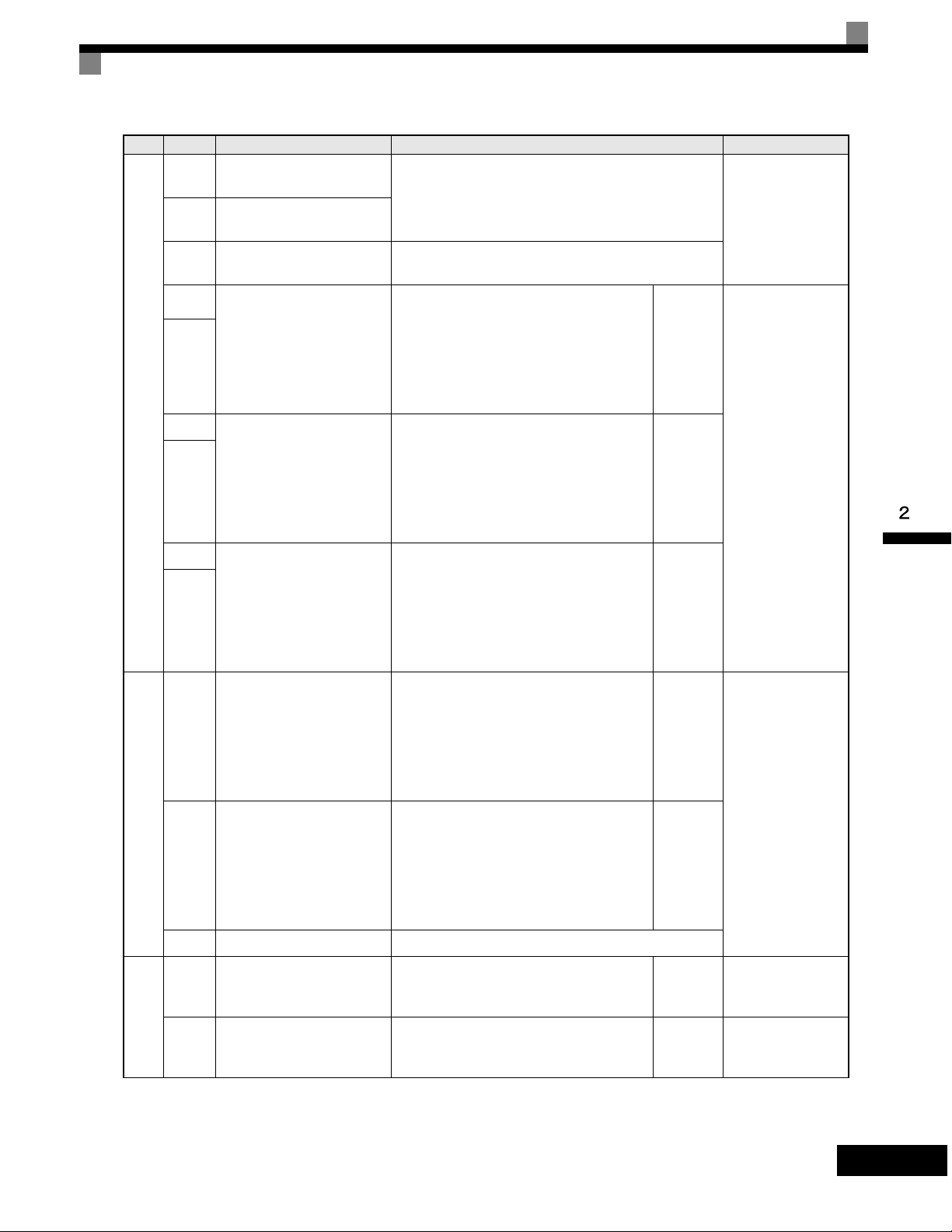
Type
Relay
outputs
Wiring Control Circuit Terminals
Table 2.10 Control Circuit Terminals (Continued)
No. Signal Name Function Signal Level
MA
MB
MC
M1
Fault output signal
(NO contact)
Fault output signal
(NC contact)
Relay contact output
common
MA / MC: Closed during fault condition
MB / MC: Open during fault condition
-
Form C
Dry contacts
capacity:
1 A max. at 250 Vac
1 A max. at 30 Vdc
Multi-
function
M2
Multi-function contact
output
(NO contact)
Factory setting: Operating
Operating when CLOSED across M1 and
M2.
digital
output.
Function
set by
H2-01
M3
M4
Multi-function contact
output 2
Factory setting: Zero speed
Zero speed level (b2-01) or below when
CLOSED.
Multi-
function
digital
output.
Function
set by
Form A
Dry contacts
capacity:
1 A max. at 250 Vac
1 A max. at 30 Vdc
H2-02
Analog
monitor
outputs
Pulse
I/O
M5
Factory setting: Frequency
M6
Multi-function contact
output 3
agreement detection
Frequency within 2 Hz of set
frequency when CLOSED.
FM
Multi-function analog
monitor 1
0 to +10Vdc / 100% frequency
-10 to +10Vdc / 100% frequency
4 to 20mA / 100% frequency
0 to +10Vdc / 100% Drive's rated
output current
AM
Multi-function analog
monitor 2
-10 to +10Vdc / 100% Drive's rated output
current
4 to 20mA / 100% Drive's rated output cur-
rent
AC Analog common -
RP
Multi-function pulse input
MP
Multi-function pulse
monitor
*3
Factory setting: Frequency reference
Factory setting: Output frequency
Multi-
function
digital
output.
Function
set by
H2-03
Multi-
function
analog
output 1.
Function
set by
H4-01
Multi-
function
analog
output 2.
Function
set by
H4-04
Function
set by
H6-01
Function
set by
H6-06
0 to +10 Vdc ±5%
2 mA max.
0 to 32 kHz (3 kΩ)
0 to 32 kHz (2.2 kΩ)
2-25
Page 57
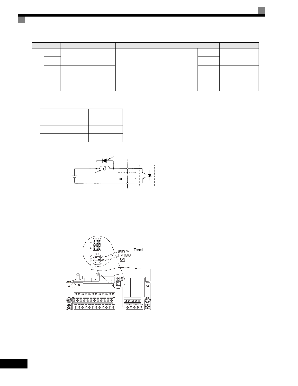
Table 2.10 Control Circuit Terminals (Continued)
Typ e
RS-
485/
422
No. Signal Name Function Signal Level
R+
R-
S+
S-
MODBUS
communications input
MODBUS
communications output
For 2-wire RS-485, short R+ and S+ as well
as R- and S-.
Differential input,
PHC isolation
Differential output,
PHC isolation
IG Communications shield wire - -
* 1. For a 3-wire sequence, the default settings are a 3-wire sequence for S5, multi-step speed setting 1 for S6 and multi-step speed setting 2 for S7.
* 2. When driving a reactive load, such as a relay coil, always insert a flywheel diode as shown in Fig 2.14.
* 3. Pulse input specifications are given in the following table.
Low level voltage 0.0 to 0.8 V
High level voltage 3.5 to 13.2 V
H duty 30% to 70%
Pulse frequency 0 to 32 kHz
Flywheel diode
External power:
48 V max.
Coil
50 mA max.
Fig 2.14 Flywheel Diode Connection
Shunt Connector CN15 and DIP Switch S1
The shunt connector CN15 and DIP switch S1 are described in this section.
Analog output switch
Voltage output
Current output
Terminating resistance*
ON
OFF
Analog input switch
Factory settings
*Note: Refer to Table 2.11 for S1 functions and
The rating of the flywheel diode
must be at least as high as the
circuit voltage.
to Table 2.13 for Sinking/Sourcing Mode
and Input Signals.
2-26
Fig 2.15 Shunt Connector CN15 and DIP Switch S1
Page 58

The functions of DIP switch S1 are shown in the following table.
Table 2.11 DIP Switch S1
Name Function Setting
S1-1
RS-485 and RS-422 terminating resistance
OFF: No terminating resistance
ON: Terminating resistance of 110 Ω
Wiring Control Circuit Terminals
S1-2 Input method for analog input A2
OFF: 0 to 10 V (internal resistance: 20 kΩ)
ON: 4 to 20 mA (internal resistance: 250 Ω)
The functions and positions of CN15 are shown in the following table.
Table 2.12 Jumper CN15 Configuration Options
Jumper CN15 Configuration Analog Output Monitor Configuration
Voltage Output (0-10Vdc) for terminals FM-AC (CH1) and AM-AC (CH2)
Current Output (4-20mA) for terminals FM-AC (CH1) and AM-AC (CH2)
Voltage Output (0-10Vdc) for terminals FM-AC (CH1)
Current Output (4-20mA) for terminals AM-AC (CH2)
Current Output (4-20mA) for terminals FM-AC (CH1)
Voltage Output (0-10Vdc) for terminals AM-AC (CH2)
2-27
Page 59

Sinking/Sourcing Mode
The multi-function input terminal logic can be switched between sinking mode (0 Vdc common) and sourcing
mode (+24 Vdc common) by using the terminals SN, SC, and SP. An external 24 Vdc power supply is also supported, providing more freedom in signal input methods.
Table 2.13 Sinking/Sourcing Mode and Input Signals
Internal Power Supply External Power Supply
Sinking
Mode
Sourcing
Mode
S1
S2
SN
SC
SP
S1
S2
SN
SC
SP
IP24V(+24V)
IP24V(+24V)
External +24V
External +24V
S1
S2
SN
SC
IP24V(+24V)
SP
S1
S2
SN
SC
IP24V(+24V)
SP
2-28
Page 60

Control Circuit Terminal Connections
Connections to Drive control circuit terminals are shown in Fig 2.16.
DC Link Choke
Standard:
Branch circui t
protection supplied
by others.
CIMR-G7U2018 t o 2110
CIMR-G7U4018 t o 4300
Shorting Bar Standard:
CIMR-G7U20P4 to 2015
CIMR-G7U40P4 to 4015
UX
Remove if addi ng
external DC link
choke
Wiring Control Circuit Terminals
12 Pulse Input Terminals R1/L11, S1/L21, T1/L31 are standard
on CIMR-G7U2018 - 2110 and CIMR-G7U4018 - 4300.
External Braking Terminal 3 is standard on CIMR-G7U2018
- 2110 and CIMR-G7U4018 - 4300.
Braking Terminals B1, B2 are standard on CIMR-G7U20P4 2015 and CIMR-G7U40P4- 4015.
+
3-Phase
Power Su pply
50/60Hz
Digital Inputs
24VDC, 8mA
Multi-function
Digital Inputs
24VDC, 8 mA
L1
L2
L3
External
Frequency
Reference
MCCB
Foward Run/Stop
Reverse Run/ Stop
External Fault
Fault Reset
Multi-Step Reference1
Multi-Step Reference2
Jog Reference
Baseblock
Multi-Step Reference3
Multi-Step Reference4
Accel / Decel Time 1
Fast-Stop N.O.
2k Ω
Modbus RTU
Communicatio ns
RS-485/422
19.2 Kbps
Remove jumpers if
using 12 pulse input
2k
Ω
Resistor
Ω
S1-1
3
G7
Ω
(S1-2 ON)
Ω
Ω
Ω
-
(H2-01)
(H2-02)
(H2-03)
(H2-04)
(H2-05)
(S1-2 OFF)
Ω
Jumper CN15
CH1
CH2
DIP Swit ch S1
OFF ON
+1+2+
R/L1
S/L2
T/L3
R/L11
S/L21
T/L31
S1
S2
S3 (H1-01)
S4 (H1-02)
S5 (H1-03)
S6 (H1-04)
S7 (H1-05)
S8 (H1-06)
S9 (H1-07)
S10 (H1-08)
S11 (H1-09)
S12 (H1-10)
SN
SC
SP +24VDC
E(G)
+V +15VDC +/- 10%, 20mA
-V -15VDC +/-10%, 20mA
A1 0 to +/-10VDC, 20 k *
A2 4 to 20mA, 250 *
[0 to +/-10VDC, 20k **]
Multi-function Anal og Input 1 (H3-09)
A3 0 to +/ -10VDC, 20k *
Multi-function Anal og Input 2 (H3-05)
RP 0 to 32kHz, 5 to 12VDC, 3k ***
Multi-function Pul se Input (H6-01)
AC
Terminating
110
R+
R-
S+
S-
IG
B1 B2
(H4-01) FM
(H4-04) AM
(H6-06) MP
V
S1-1
S1-2
U/T1
V/T2
W/T3
MA
MB
MC
M1
M2
M3
M4
M5
M6
C3
C4
E(G)
AC
Digital Output 1
Fault Contact
250VAC, 30VDC, 1A
During Run
Zero Speed
Frequency Agree 1
P3
Inverter Ready
P4
Minor Fault - Alarm
+ -
+-
See Page 2-25 for details.
* +/-11 Bit Resolution, 0.2% Accuracy
** 10 Bit Resolution, 0.2% Accuracy
*** +/-1% Acc uracy
Motor
T1
M
T2
T3
Multi-function
Digital Outputs 2-4
250VAC, 30VDC, 1A
Multi-function
Digital Outputs 5-6
48VDC, 50mA
Output Frequency
Output Current
Output Frequency
Multi-function
Analog Outp ut 1 - 2
0 to +/-10VDC, 2mA
4-20mA, 500
+/-9 Bit Resolution
+/- 8% Accuracy
Multi-function
Pulse Output
0 to 32kHz
9VDC @ 3k
+/-1% Accuracy
Ω
Ω
Fig 2.16 Control Circuit Terminal Connections
2-29
Page 61

Control Circuit Wiring Precautions
Observe the following precautions when wiring control circuits.
• Separate control circuit wiring from main circuit wiring (terminals R/L1, S/L2, T/L3, B1, B2, U/T1, V/T2,
W/T3, , 1, 2, and 3) and other high-power lines.
• Separate wiring for control circuit terminals MA, MB, MC, M1, M2, M3, M4, M5, and M6 (contact
outputs) from wiring to other control circuit terminals.
• Use twisted-pair or shielded twisted-pair cables for control circuits to prevent operating faults. Process
cable ends as shown in Fig 2.17.
• Connect the shield wire to terminal E (G).
• Insulate the shield with tape to prevent contact with other signal lines and equipment.
Shield sheath
Connect to shield sheath
terminal at Drive
(terminal E (G))
Fig 2.17 Processing the Ends of Twisted-pair Cables
Insulate with tape
Armor
Do not connect here.
Control Circuit Wire Sizes
For remote operation, keep the length of the control wiring to 50m or less. Separate the control wiring from highpower lines (input power, motor leads or relay sequence circuits) to reduce noise induction from peripheral devices.
When setting speed commands from an external speed potentiometer, use shielded twisted-pair wires and ground the
shield to terminal E(G), as shown above. Terminal numbers and wire sizes are shown in Table 2.9.
2-30
Wiring Checks
Check all wiring after wiring has been completed. Do not perform a buzzer check on control circuits. Perform
the following checks on the wiring.
• Is all wiring correct?
• Have any wire clippings, screws, or other foreign material been left?
• Are all screws tight?
• Are any wire ends contacting other terminals?
Page 62

Installing and Wiring Option Cards
Installing and Wiring Option Cards
Option Card Models and Specifications
Up to three Option Cards can be mounted in the Drive. You can mount up one card into each of the three
places on the controller card (A, C, and D) shown in Fig 2.18.
Table 2.14 lists the type of Option Cards and their specifications.
Table 2.14 Option Card Specifications
Card Model Specifications
PG-A2 Serial open-collector/complimentary inputs A
PG Speed Control Cards
PG-B2 Phase A/B complimentary inputs A
PG-D2 Single line-driver inputs A
PG-X2 Phase A/B line-driver inputs A
Input signal levels
AI-14U
0 to 10 V DC (20 kΩ), 1 channel
4 to 20 mA (250 Ω), 1 channel
Input resolution: 14-bit
Mounting
Location
C
Speed Reference Cards
DeviceNet Communications
Card
Profibus-DP Communications Card
Analog Monitor Card
Digital Output Card
Input signal levels
AI-14B
DI-08 8-bit digital speed reference setting C
DI-16H2 16-bit digital speed reference setting C
SI-N DeviceNet communications support C
SI-P Profibus-DP communications support C
AO-08 8-bit analog outputs, 2 channels D
AO-12 12-bit analog outputs, 2 channels D
DO-08 Six photocoupler outputs and 2 relay outputs D
DO-02C 2 relay outputs D
0 to 10 V DC (20 kΩ)
4 to 20 mA (250 Ω), 3 channels
Input resolution: 13-bit with sign bit
C
2-31
Page 63

Installation
r
Before mounting an Option Board, remove power from the Drive and wait for the CHARGE LED to go out.
Remove the Digital Operator, front cover, and option clip. Option Clip can be easily removed by squeezing
the protruding portions of the clip and then pulling it out. Then, mount the Option Board(s).
The A Option Board uses a mounting spacer to secure the board to the control board. Insert the mounting
spacer as shown in Fig 2.18.
After installing an Option Board into slot C or D, insert the Option Clip to prevent the side with the connector
from rising.
Refer to documentation provided with the Option Board for detailed mounting instructions for option slots A,
C, and D.
A Option Card mounting spacer
(Provided with A Option Card.)
A Option Card mounting spacer hole
4CN
A Option Card connector
2CN
C Option Card connector
C Option Card mounting spacer
Option Clip
(To prevent raising of
C and D Option Cards)
3CN
D Option Card connector
A Option Card
Fig 2.18 Mounting Option Cards
C Option Card
D Option Card
D Option Card mounting space
A Option Card mounting spacer
2-32
Page 64

PG Speed Control Card Terminals and Specifications
The terminal specifications for the PG Speed Control Cards are given in the following tables.
PG-A2
The terminal specifications for the PG-A2 are given in the following table.
Table 2.15 PG-A2 Terminal Specifications
Te rm in al No. Contents Specifications
1
Power supply for pulse generator
2 0 Vdc (GND for power supply)
12 Vdc (±5%), 200 mA max.
Installing and Wiring Option Cards
3
+12 V/open collector switching terminal
TA1
TA2 (E) Shield connection terminal -
4
5
Pulse input terminal
6 Pulse input common
7
Pulse motor output terminal
8 Pulse monitor output common
Terminal for switching between12 Vdc voltage input
and open collector input. For open collector input,
short across 3 and 4.
H: +4 to 12 Vdc; L: +1 Vdc max. (Maximum response
frequency: 30 kHz)
12 Vdc (±10%), 20 mA max.
2-33
Page 65
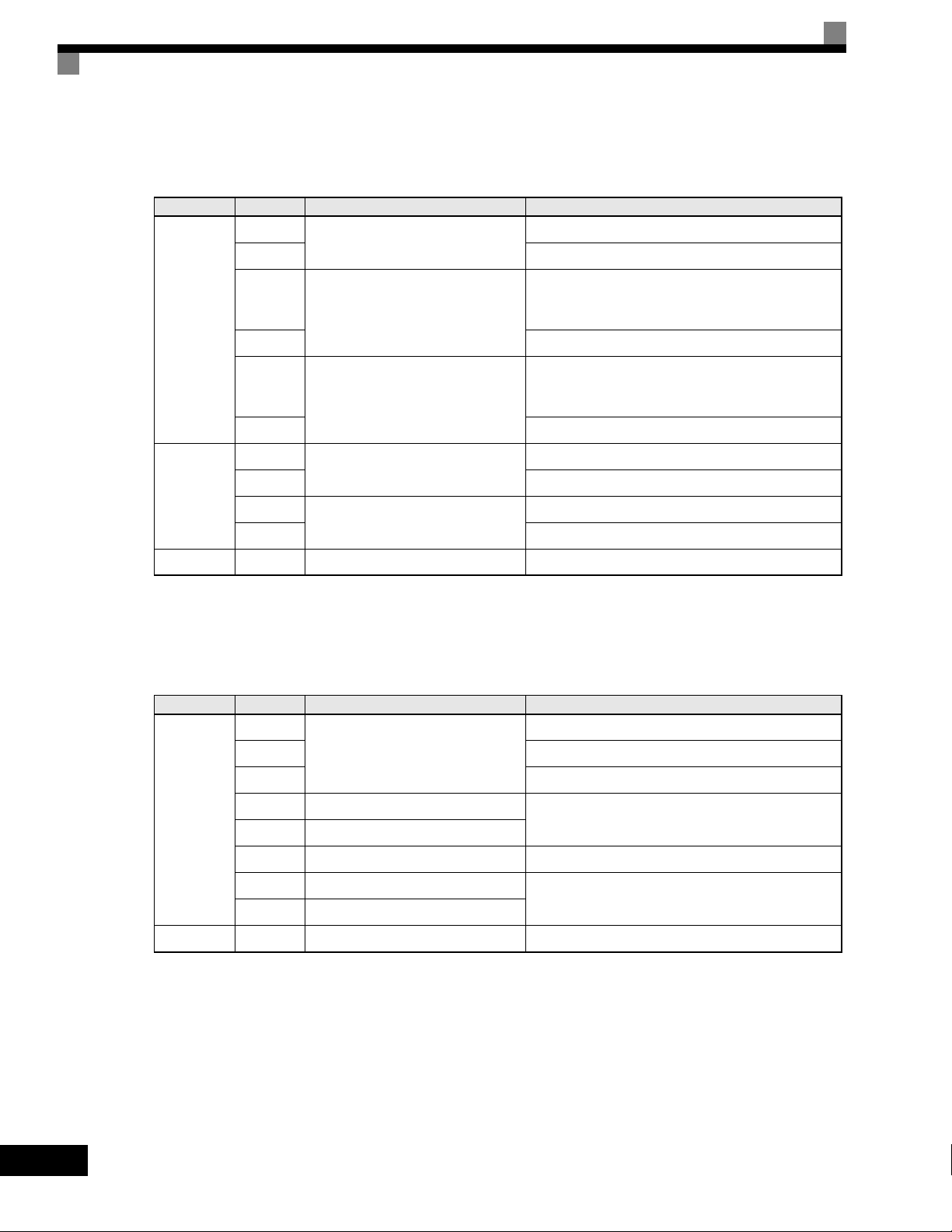
PG-B2
The terminal specifications for the PG-B2 are given in the following table.
Table 2.16 PG-B2 Terminal Specifications
Te rm in al No. Contents Specifications
1
Power supply for pulse generator
2 0 Vdc (GND for power supply)
3
A-phase pulse input terminal
TA 1
4 Pulse input common
5
B-phase pulse input terminal
6 Pulse input common
1
A-phase monitor output terminal
2 A-phase monitor output common
TA 2
3
B-phase monitor output terminal
4 B-phase monitor output common
TA3 (E) Shield connection terminal -
12 Vdc (±5%), 200 mA max.
H: +8 to 12 Vdc
L: +1 Vdc max.
(Maximum response frequency: 30 kHz)
H: +8 to 12 Vdc
L: +1 Vdc max.
(Maximum response frequency: 30 kHz)
Open collector output, 24 Vdc, 30 mA max.
Open collector output, 24 Vdc, 30 mA max.
PG-D2
The terminal specifications for the PG-D2 are given in the following table.
Table 2.17 PG-D2 Terminal Specifications
Te rm in al No. Contents Specifications
1
Power supply for pulse generator
2 0 Vdc (GND for power supply)
3 5 Vdc (±5%), 200 mA max.*
TA 1
TA2 (E) Shield connection terminal -
* 5 Vdc and 12 Vdc cannot be used at the same time.
4 Pulse input + terminal
5 Pulse input - terminal
6Common terminal -
7 Pulse monitor output + terminal
8 Pulse monitor output - terminal
12 Vdc (±5%), 200 mA max.*
Line driver input (RS-422 level input)
Maximum response frequency: 300 kHz
Line driver output (RS-422 level output)
2-34
Page 66

Installing and Wiring Option Cards
PG-X2
The terminal specifications for the PG-X2 are given in the following table.
Table 2.18 PG-X2 Terminal Specifications
Te rm in al No. Contents Specifications
TA1
1
Power supply for pulse generator
2 0 Vdc (GND for power supply)
3 5 Vdc (±5%), 200 mA max.*
4 A-phase + input terminal
5 A-phase - input terminal
6 B-phase + input terminal
7 B-phase - input terminal
8 Z-phase + input terminal
9 Z-phase - input terminal
10 Common terminal 0 Vdc (GND for power supply)
1 A-phase + output terminal
12 Vdc (±5%), 200 mA max.*
Line driver input (RS-422 level input)
Maximum response frequency: 300 kHz
2 A-phase - output terminal
3 B-phase + output terminal
TA2
TA3 (E) Shield connection terminal -
* 5 Vdc and 12 Vdc cannot be used at the same time.
4 B-phase - output terminal
5 Z-phase + output terminal
6 Z-phase - output terminal
7 Control circuit common Control circuit GND
Line driver output (RS-422 level output)
2-35
Page 67
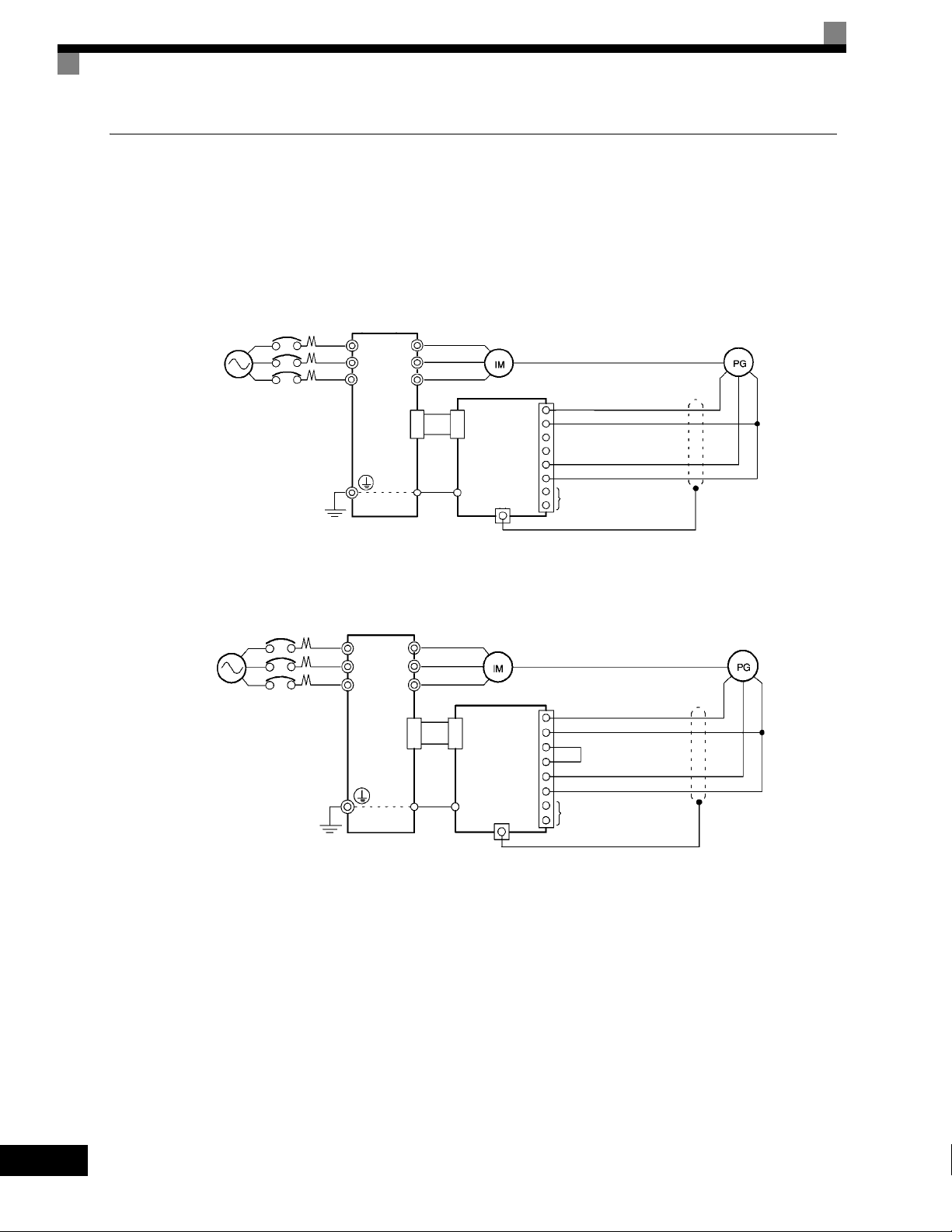
Wiring
Wiring examples are provided in the following illustrations for the Control Cards.
Wiring the PG-A2
Wiring examples are provided in the following illustrations for the PG-A2.
Three-phase, 200-240
Vac (380-480 Vac)
Drive
R/L1
V/T2
W/T3
Fig 2.19 Wiring a 12 V Voltage Input
Three-phase, 200240 Vac (380-480 Vac) Drive
R/L1
V/T2
W/T3
U/T1
V/T2
W/T3
4CN
U/T1
V/T2
W/T3
4CN
PG-A2
4CN
TA1
E
E
E
TA2 (E )
PG-A2
4CN
TA1
E
TA2 (E )
+12 Vdc power supply
1
0 Vdc power supply
2
3
4
12 Vdc voltage input (A/B phase)
5
Pulse 0 Vdc
6
7
Pulse monitor output
8
+12 Vdc power supply
1
0 Vdc power supply
2
3
4
Open collector output (A/B phase)
5
Pulse 0 Vdc
6
7
Pulse monitor output
8
2-36
•
Shielded twisted-pair wires must be used for signal lines.
• Do not use the pulse generator's power supply for anything other than the pulse generator (encoder).
Using it for another purpose can cause malfunctions due to noise.
• The length of the pulse generator's wiring must not be more than 100 meters (328 ft).
Fig 2.20 Wiring an Open-collector Input
Page 68
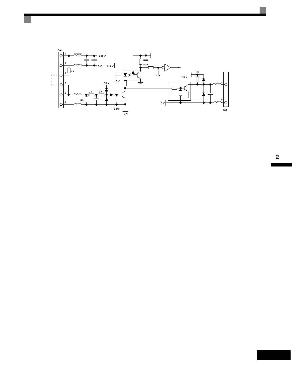
PG power
supply
+12 Vdc
Short for
opencollector
input
Pulse
input
Pulse input
Fig 2.21 I/O Circuit Configuration of the PG-A2
Installing and Wiring Option Cards
Pulse
monitor
output
2-37
Page 69
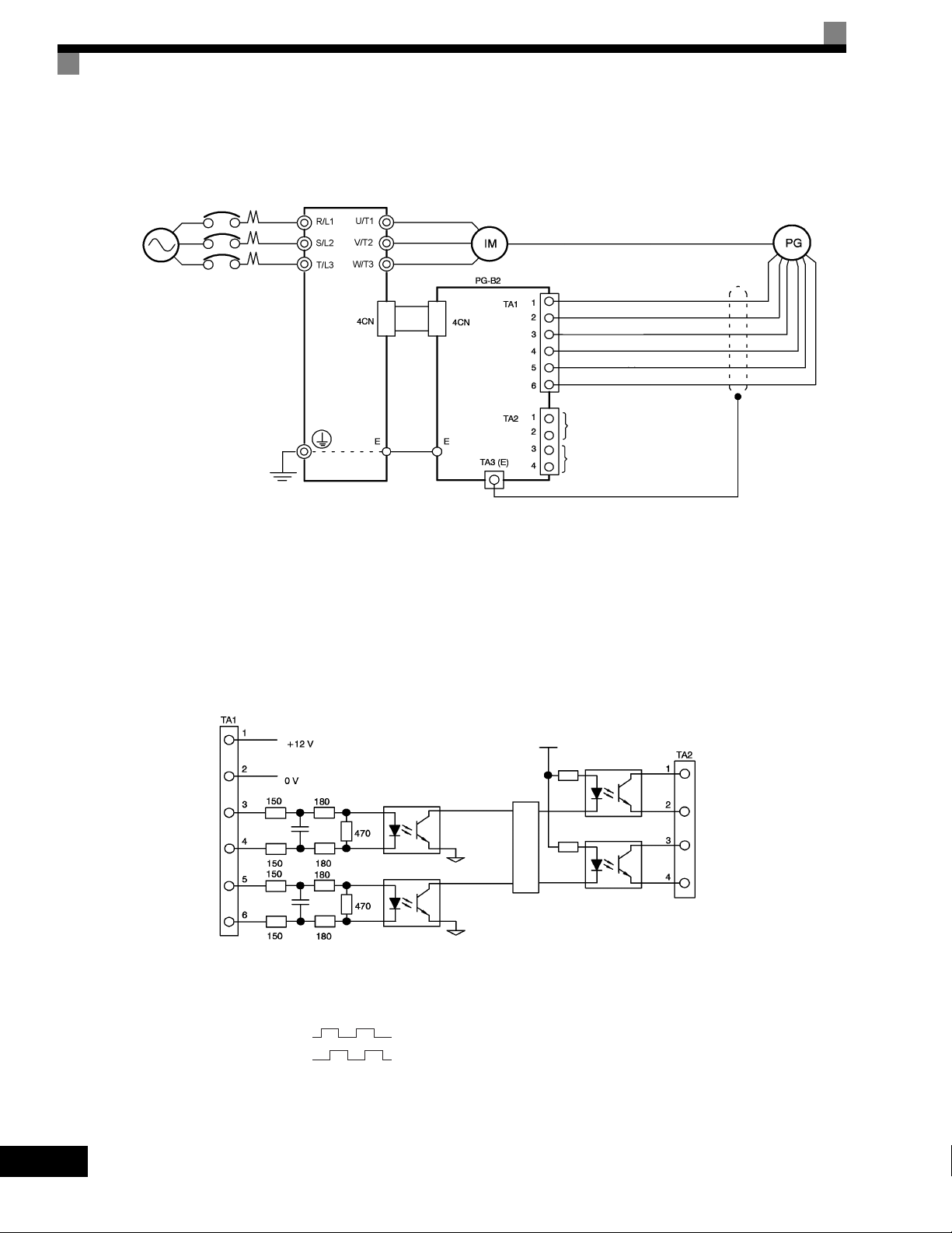
Wiring the PG-B2
Wiring examples are provided in the following illustrations for the PG-B2.
Three-phase
200-240 Vac
(380-480 Vac)
Drive
Power supply +12 Vdc
Power supply 0 Vdc
A-phase pulse output (+)
A-phase pulse output (-)
B-phase pulse output (+)
B-phase pulse output (-)
A-phase pulse monitor output
B-phase pulse monitor output
• Shielded twisted-pair wires must be used for signal lines.
• Do not use the pulse generator's power supply for anything other than the pulse generator (encoder).
Using it for another purpose can cause malfunctions due to noise.
• The length of the pulse generator's wiring must not be more than 100 meters (328 ft).
• The direction of rotation of the PG can be set in user parameter F1-05. The factory preset if for forward
rotation, A-phase advancement.
PG power
supply +12
Vdc
A-phase pulse
input
B-phase pulse
input
Fig 2.22 PG-B2 Wiring
A-phase pulse
monitor output
A-phase
pulses
B-phase pulse
monitor output
B-phase
Division rate circuit
pulses
• When connecting to a voltage-output-type PG (encoder), select a PG that has an output impedance with
a current of at least 12 mA to the input circuit photocoupler (diode).
• The pulse monitor dividing ratio can be changed using parameter F1-06.
A-phase pulses
B-phase pulses
Fig 2.23 I/O Circuit Configuration of the PG-B2
2-38
Page 70
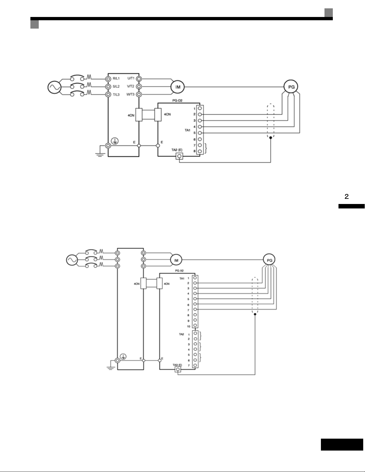
Wiring the PG-D2
Wiring examples are provided in the following illustrations for the PG-D2.
Installing and Wiring Option Cards
Three-phase
200-240 Vac
(380-480 Vac)
Drive
• Shielded twisted-pair wires must be used for signal lines.
• Do not use the pulse generator's power supply for anything other than the pulse generator (encoder).
Using it for another purpose can cause malfunctions due to noise.
• The length of the pulse generator's wiring must not be more than 100 meters.
Fig 2.24 PG-D2 Wiring
Wiring the PG-X2
Wiring examples are provided in the following illustrations for the PG-X2.
Three-phase
200-240 Vac
(380-480 Vac)
Drive
R/L1
S/L2
U/T1
V/T2
W/T3T/L3
Power supply +12 Vdc
Power supply 0 Vdc
Power supply +5 Vdc
Pulse input + (A/B phase)
Pulse input - (A/B phase)
Pulse monitor output
Power supply +12 Vdc
Power supply 0 Vdc
Power supply +5 Vdc
A-phase pulse input (+)
A-phase pulse input (-)
B-phase pulse input (+)
B-phase pulse input (-)
A-phase pulse monitor output
B-phase pulse monitor output
Z-phase pulse monitor output
• Shielded twisted-pair wires must be used for signal lines.
• Do not use the pulse generator's power supply for anything other than the pulse generator (encoder).
Using it for another purpose can cause malfunctions due to noise.
• The length of the pulse generator's wiring must not be more than 100 meters (328 ft).
• The direction of rotation of the PG can be set in user parameter F1-05 (PG Rotation). The factory preset
if for motor forward rotation, A-phase advancement.
Fig 2.25 PG-X2 Wiring
2-39
Page 71
Wiring Terminal Blocks
Use no more than 100 meters (328 ft) of wiring for PG (encoder) signal lines, and keep them separate from
power lines.
Use shielded, twisted-pair wires for pulse inputs and pulse output monitor wires, and connect the shield to the
shield connection terminal.
Wire Sizes (Same for All Models)
Terminal wire sizes are shown in Table 2.19.
Table 2.19 Wire Sizes
Ter mi na l
Pulse generator power supply
Pulse input terminal
Pulse monitor output terminal
Shield connection terminal M3.5 0.5 to 2
Terminal
Screws
-
Wire Thickness (mm2)
Stranded wire: 0.5 to 1.25
Single wire: 0.5 to 1.25
Wire Type
• Shielded, twisted-pair wire
• Shielded, polyethylene-covered, vinyl
sheath cable
Straight Solderless Terminals for Control Circuit Terminals
We recommend using straight solderless terminals on signal lines to simplify wiring and improve reliability.
Closed-loop Connector Sizes and Tightening Torque
The closed-loop connectors and tightening torques for various wire sizes are shown in Table 2.20.
Table 2.20 Closed-loop Connectors and Tightening Torques
Wire Thickness [mm2]
0.5
0.75 1.25 - 3.5
1.25 1.25 - 3.5
22 - 3.5
Te rm in al
Screws
M3.5
Crimp Terminal Size Tightening Torque (N • m)
1.25 - 3.5
0.8
2-40
Wiring Method and Precautions
Observe the following precautions when wiring.
• Separate the control signal lines for the PG Speed Control Card from main circuit lines and power lines.
• Connect the shield when connecting to a PG. The shield must be connected to prevent operational errors
caused by noise. Also, do not use any lines that are more than 100 m (328 ft) long. Refer to Fig 2.17 for
details on connecting the shield.
• Connect the shield to the shield terminal (E).
• Do not solder the ends of wires. Doing so may cause contact faults.
• When not using straight solderless terminals, strip the wires to a length of approximately 5.5 mm (0.2 in).
Page 72
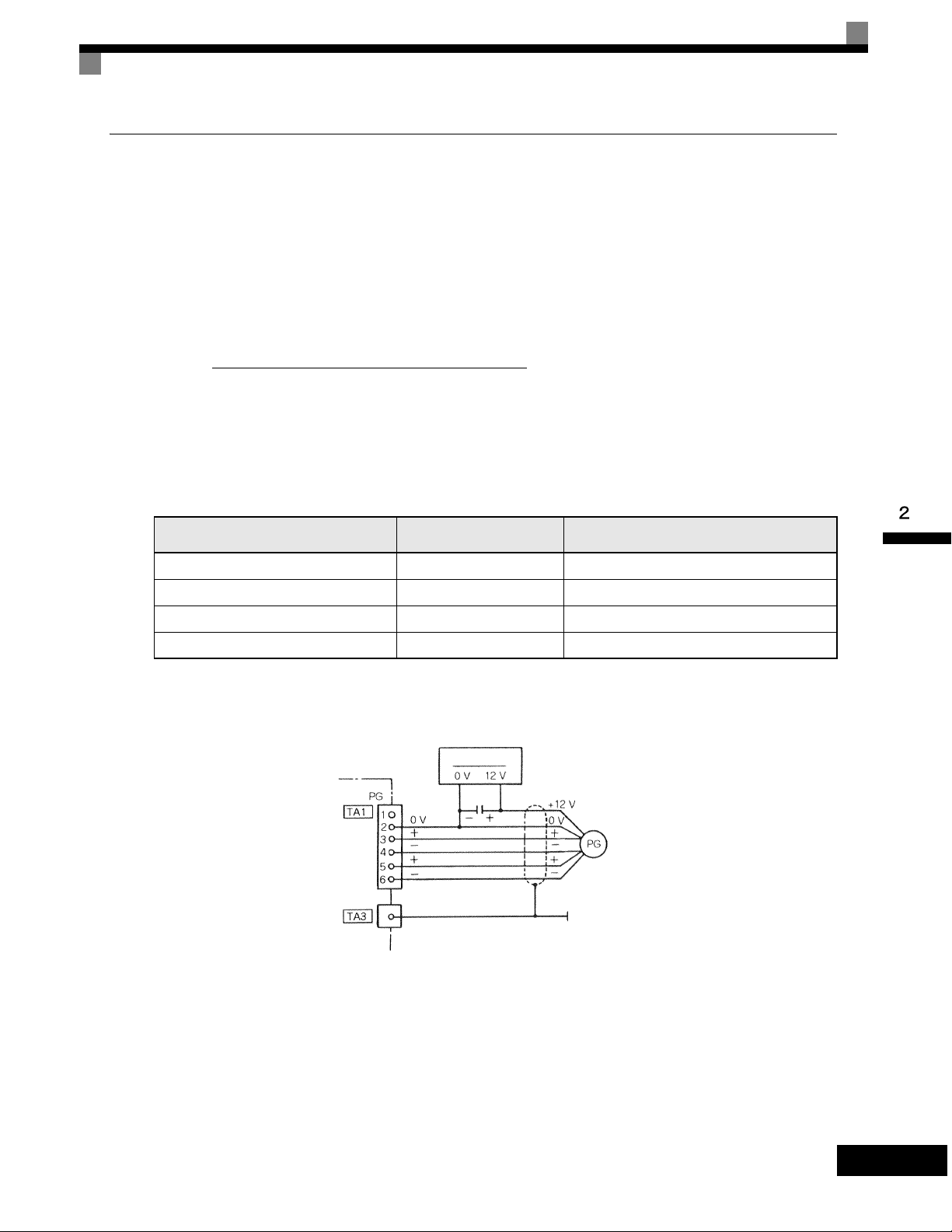
Installing and Wiring Option Cards
Selecting the Number of PG (Encoder) Pulses
The setting for the number of PG pulses depends on the model of PG Speed Control Card being used. Set the
correct number for your model.
PG-A2/PG-B2
The maximum response frequency is 32,767 Hz.
Use a PG that outputs a maximum frequency of approximately 20 kHz for the rotational speed of the motor.
f
PG
(Hz) =
Motor speed at maximum frequency output (RPM)
60
× PG rating (ppr)
Some examples of PG output frequency (number of pulses) for the maximum frequency output are shown in
Table 2.21.
Table 2.21 PG Pulse Selection Examples
Motor's Maximum Speed (RPM)
1800 600 18,000
1500 800 20,000
1200 1000 20,000
900 1200 18,000
Note 1. The motor speed at maximum frequency output is expressed as the sync rotation speed.
2. The PG power supply is 12 Vdc.
3. A separate power supply is required if the PG power supply capacity is greater than 200 mA. (If momentary power loss must be handled, use a
backup capacitor or other method.)
PG Rating
(ppr)
PG power supply
Capacitor f or momenta ry
power loss
PG Output Frequency for Maximum
Frequency Output (Hz)
Signals
Fig 2.26 PG-B2 Connection Example
2-41
Page 73
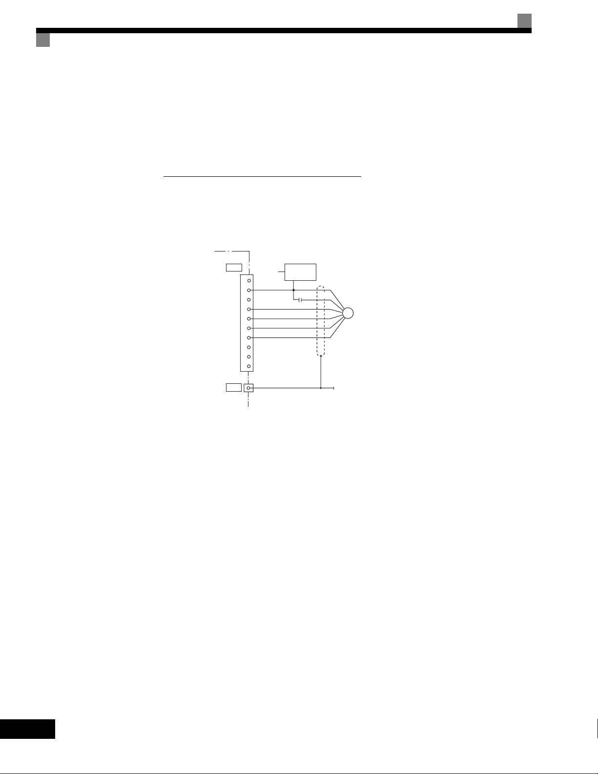
PG-D2/PG-X2
There are 5 Vdc and 12 Vdc PG power supplies.
Check the PG power supply specifications before connecting.
The maximum response frequency is 300 kHz.
Use the following equation to computer the output frequency of the PG (f
Motor speed at maximum frequency output (RPM)
(Hz) =
PG
60
).
PG
× PG rating (ppr)f
A separate power supply is required if the PG power supply capacity is greater than 200 mA. (If momentary
power loss must be handled, use a backup capacitor or other method.)
PG-X2
TA1
IP12
IG
IP5
A (+)
A (-)
B (+)
B (-)
Z (+)
Z (-)
IG
TA3
1
2
3
4
5
6
7
8
9
10
Capacitor for
momentary
power loss
AC
PG power
supply
0V +12V
+
+12 V
0 V
+
PG
-
+
-
Fig 2.27 PG-X2 Connection Example (for 12 Vdc PG power supply)
2-42
Page 74

3
Digital Operator and Modes
This chapter describes Digital Operator displays and functions, and provides an overview of
operating modes and switching between modes.
Digital Operator............................................................3-2
Modes..........................................................................3-5
Page 75

Digital Operator
The Digital Operator is used for programming, operating, monitoring, and copying the Drive’s parameters. To copy parameters, G7 Drives must have the same software version, model, and control method. The
various items included on the Digital Operator are described below.
-DRIVE- Rdy
Menu Display
- - - - - - - - - - - - - - - - - - - - - - - - - - - - -
U1-02= 60.00Hz
U1-03= 10.05A
Frequency Ref
U1-01= 60.00Hz
Drive Mode Indicators
See Table 3.2
Ready Display
Drive can operate when a Drive command is input
Data Display
Displays monitor data, parameter data and settings
1 line x 13 characters
3 lines x 16 characters
Key Descriptions
See Table 3.1
Factory Default
Setting
-QUICK-
Co ntr ol Me tho d
---------------------------------
A1-02= 3 *3*
Flux Vector
“2”
RUN & STOP Indicators
See Tables 3.5 and 3.6
Currently Programmed Value
Present Selection (User adjusts)
3-2
Page 76

Digital Operator Keys
The names and functions of the Digital Operator Keys are described in Tab le 3. 1.
Table 3.1 Key Functions
Key Name Function
Switches between operation via the Digital Operator (LOCAL) and
LOCAL/REMOTE Key
MENU Key Selects menu items (modes).
ESC Key Returns to the status before the DATA/ENTER Key was pressed.
control circuit terminal operation (REMOTE).
This Key can be enabled or disabled by setting user parameter o2-01.
Digital Operator
JOG Key
FWD/REV Key
Shift/RESET Key
Increment Key
Decrement Key
DATA/ENTER Key
RUN Key
STOP Key
Note Except in diagrams, Keys are referred to using the Key names listed in the above table.
Enables jog operation when the Drive is being operated from the Digital Operator.
Selects the rotation direction of the motor when the Drive is being
operated from the Digital Operator.
Sets the number of digits for user parameter settings.
Also acts as the Reset Key when a fault has occurred.
Selects menu items, sets user parameter numbers, and increments set
values.
Used to move to the next item or data.
Selects menu items, sets user parameter numbers, and decrements set
values.
Used to move to the previous item or data.
Pressed to enter menu items, user parameters, and set values.
Also used to switch from one display to another.
Starts the Drive operation when the Drive is being controlled by the
Digital Operator.
Stops Drive operation.
This Key can be enabled or disabled when operating from the control
circuit terminal by setting user parameter o2-02.
3-3
Page 77

Drive Mode Indicators
The definition of the Drive mode indicators are shown in Table 3.2.
Table 3.2 Drive Mode Indicators
Indicator Definition
FWD Lit when a forward run command is input.
REV Lit when a reverse run command is input.
REMOTE SEQ See Table 3.3.
REMOTE REF See Table 3.4.
ALARM Lit when a fault has occurred. Flashes when an Alarm has occurred.
REMOTE Sequence (SEQ) Indicator
The status of the “REMOTE” Sequence (SEQ) indicator is shown in Table 3.3. This indicator is always “Off” when the Drive is
in the “LOCAL” mode. When the Drive is in the “REMOTE” mode, the SEQ indicator status is dependent on the setting of
parameter b1-02 (Run Command Selection). See Table 3.3.
Table 3.3 REMOTE Sequence (SEQ) Indicator
Indicator Status Condition
Parameter b1-02 (Run Command Selection) is set to terminal strip, communications, or an option
board as indicated below:
On
Off
b1-02 =1 (Terminals)
=2 (Communications)
=3 (Option PCB)
Parameter b1-02 (Run Command Selection) is set to Digital Operator as indicated below:
b1-02=0 (Operator)
REMOTE Reference (REF) Indicator
The status of the “REMOTE” Reference (REF) indicator is shown in Table 3.4. This indicator is always “Off” when the Drive is
in the “LOCAL” mode. When the Drive is in the “REMOTE” mode, the REF indicator status is dependent on the setting of
parameter b1-01 (Frequency Reference Selection). See Table 3.4.
Table 3.4 REMOTE Reference (REF) Indicator
Indicator Status Condition
Parameter b1-01 (Frequency Reference Selection) is set to terminal strip, communications, option
board, or pulse train as indicated below:
On
b1-01 =1 (Terminals)
=2 (Communications)
=3 (Option PCB)
=4 (Pulse Train)
3-4
Off
Parameter b1-01 (Frequency Reference Selection) is set to digital
operator as indicated below:
b1-01=0 (Operator)
Page 78

Drive Mode Indicators
Run Indicator
The status of the “RUN” indicator is shown in Table 3.5 when the Drive is in either the “LOCAL” or “REMOTE” mode.
Table 3.5 RUN Indicator
Indicator Status Condition
On Drive is running.
Blinking Drive is decelerating to a stop.
Off Drive is stopped.
Stop Indicator
The status of the “STOP” indicator is shown in Table 3.6 when the Drive is in either the “LOCAL” or “REMOTE” mode.
Table 3.6 STOP Indicator
Indicator Status Condition
On Drive is decelerating to a stop or stopped.
Drive is in a run condition but the frequency reference is less than the
Blinking
Off Drive is running.
minimum output frequency E1-09, or the Drive is running in “REMOTE” mode and the
“STOP” key on has been pressed.
Modes
This section describes the Drive's modes and switching between modes.
Drive Modes
The Drive's user parameters and monitoring functions are organized in groups called modes that make it easier to
read and set user parameters.The Drive is equipped with 5 modes.
The 5 modes and their primary functions are shown.
Table 3.7 Modes
Mode Primary function(s)
The Drive can be run in this mode.
Drive mode
Quick programming mode
Use this mode when monitoring values such as frequency references or output current, displaying fault information, or displaying the fault history.
Use this mode to reference and set the minimum user parameters to operate the
Drive (e.g., the operating environment of the Drive and Digital Operator).
Advanced programming mode Use this mode to reference and set all user parameters.
Verify mode
Autotuning mode*
* Always perform autotuning with the motor before operating using vector control. Autotuning mode will not be displayed during operation or when an
error has occurred. The default setting of the Drive is for open-loop vector control 1 (A1-02 = 2).
Use this mode to read/set user parameters that have been changed from their factory-set values.
Use this mode when running a motor with unknown motor parameters in the vector
control mode. The motor parameters are calculated and set automatically.
This mode can also be used to measure only the motor line-to-line resistance.
3-5
Page 79

Switching Modes
T
The mode selection display will appear when the MENU Key is pressed from a monitor or setting display.
Press the MENU Key from the mode selection display to switch between the modes.
Press the DATA/ENTER Key from the mode selection key to monitor data and from a monitor display to
access the setting display.
Display at Startup
-DRIVE-
Frequency Ref
U1- 01=60.00Hz
U1-02=60.00Hz
U1-03=10.05A
Rdy
Mode Selection
Display
-DRIVE-
** Main Menu **
Operation
-QUICK-
** Main Menu **
Quick Setting
-ADV-
** Main Menu **
Programming
-VERIFY-
** Main Menu **
Modified Consts
-A.TUNE-
** Main Menu **
Auto-Tuning
MENU
MENU
MENU
MENU
MENU
DATA
ENTER
ESC
DATA
ENTER
ESC
DATA
ENTER
ESC
DATA
ENTER
ESC
DATA
ENTER
ESC
Monitor Display Setting Display
Monitor
Rdy
-DRIVE-
U1 - 01=60.00Hz
U1-02=60.00Hz
U1-03=10.05A
-QUICK-
Control Method
A1-02=2
Open Loop Vector
-ADV-
Initialization
A1 - 00=1
Select Language
-VERIFY-
None Modified
-A.TUNE-
Tuning Mode Sel
T1- 01=0 1
Standard Tuning
"0"
*2*
*0*
RESET
ESC
RESET
ESC
DATA
ENTER
DATA
ENTER
ESC
*1*
Rdy
ESC
DATA
ENTER
ESC
-DRIVE-
Frequency Ref
U1- 01=060.00Hz
-QUICK-
Control Method
Open Loop Vector
-ADV-
Select Language
-DRIVE-
Reference Source
U1- 01=60.00Hz
U1-02=60.00Hz
U1-03=10.05A
-ADV-
Select Language
A1-00 =0
English
The constant number will be displayed if a
constant has been changed. Press the
DATA/ENTER Key to enable the change.
DATA
ENTER
ESC
-A.TUNE-
Tuning Mode Sel
Standard Tuning
DATA
ENTER
A1-02= 2
DATA
ENTER
A1- 00= 0
English
T1- 01= 0
"0"
Rdy
*2*
*1*
*0*
3-6
Fig 3.1 Mode Transitions
When running the Drive after using Digital Operator, press the MENU Key to select the drive mode (displayed
on the LCD screen) and then press the DATA/ENTER Key from the drive mode display to bring up the monitor
IMPORTAN
display. Run commands can't be received from any other display. (Monitor display in the drive mode will
appear when the power is turned ON.)
Page 80

Drive Mode Indicators
Drive Mode
Drive mode is the mode in which the Drive can be operated. The following monitor displays are possible in
drive mode: The frequency reference, output frequency, output current, and output voltage, as well as fault
information and the fault history.
When b1-01 (Reference selection) is set to 0, the frequency can be changed from the frequency setting display.
Use the Increment, Decrement, and Shift/RESET Keys to change the frequency. The user parameter will be
written and the monitor display will be returned to when the DATA/ENTER Key is pressed after changing the
setting.
3-7
Page 81

Example Operations
T
Key operations in drive mode are shown in the following figure.
Display at Startup
-DRIVE-
Frequency Ref
U1- 01=60.00Hz
U1-02=60.00Hz
U1-03=10.05A
Rdy
Display
-DRIVE-
** Main Menu **
Operation
-QUICK-
** Main Menu **
Quick Setting
-ADV-
** Main Menu **
Programming
-VERIFY-
** Main Menu **
Modified Consts
-A.TUNE-
** Main Menu **
Auto-Tuning
MENU
MENU
MENU
MENU
MENU
DATA
ENTER
ESC
Monitor Display Frequency Setting DisplayMode Selection
A B
Monitor
Monitor
Monitor
Rdy
Rdy
Rdy
Rdy
Rdy
-DRIVE-
U1 - 01=60.00Hz
U1-02=60.00Hz
U1-03=10.05A
-DRIVE-
U1 - 02=60.00Hz
U1-03=10.05A
U1-04= 2
-DRIVE-
U1 -40 = 10H
U1-01=60.00Hz
U1-02=60.00Hz
-DRIVE-
Fault Trace
U2 - 01=OC
U2-02= OV
U2-03=60.00Hz
-DRIVE-
Fault Trace
U2 - 02 = OV
U3-03=60.00Hz
U3-04=60.00Hz
RESET
ESC
RESET
ESC
RESET
ESC
RESET
ESC
RESET
ESC
1 2
-DRIVE-
Frequency Ref
U1- 01=60.00Hz
U1-02=60.00Hz
U1-03=10.05A
-DRIVE-
Output Freq
U1- 02=60.00Hz
U1-03=10.05A
U1-04= 2
-DRIVE-
FAN Elapsed Time
U1- 40 = 10H
U1-01=60.00Hz
U1-02=60.00Hz
1 2
3 4
-DRIVE-
Current Fault
U2 - 01 = OC
U2-02=OV
U2-03=60.00Hz
-DRIVE-
Last Fault
U2 - 02 = OV
U3-03=60.00Hz
U3-04=60.00Hz
DATA
ENTER
DATA
ENTER
Rdy Rdy
Rdy
-DRIVE-
Frequency Ref
U1 -01= 060.00Hz
ESC
The Frequency Setting
Display will not be
displayed when using an
analog reference.
Rdy
The fault name will be
displayed if the DATA/ENTER
Key is pressed while a constant
is being displayed for which a
fault code is being displayed.
DATA
ENTER
Rdy
U2 -01= OC
Over Current
ESC
DATA
Rdy
ENTER
U2 -02= OV
Rdy
DC Bus Overvolt
ESC
3 4
DATA
ENTER
U3 -01= OC
Rdy
Over Current
U3 -02= OV
Rdy
DC Bus Overvolt
-DRIVE-
Fault History
U3 - 01= OC
U3-02= OV
U3-03= OH
-DRIVE-
Fault Message 2
U3 - 02 = OV
U3-03= OH
U3-04= UV
Rdy
Rdy
RESET
ESC
RESET
ESC
5 6
-DRIVE-
Last Fault
U3 - 01 = OC
U3-02=OV
U3-03=OH
-DRIVE-
Fault Message 2
U3 - 02 = OV
U3-03= OH
U3-04= UV
Rdy
Rdy
DATA
ENTER
ESC
DATA
ENTER
ESC
5 6
A B
Fig 3.2 Operations in Drive Mode
Note When changing the display with the Increment and Decrement Keys, the next display after the one for the last parameter number will be the one for the
first parameter number and vise versa. For example, the next display after the one for U1-01 will be U1-40. This is indicated in the figures by the letters
A and B and the numbers 1 to 6.
3-8
The display for the first monitor parameter (frequency reference) will be displayed when power is turned ON.
The monitor item displayed at startup can be set in o1-02 (Monitor Selection after Power Up).
Operation cannot be started from the mode selection display.
IMPORTAN
Page 82
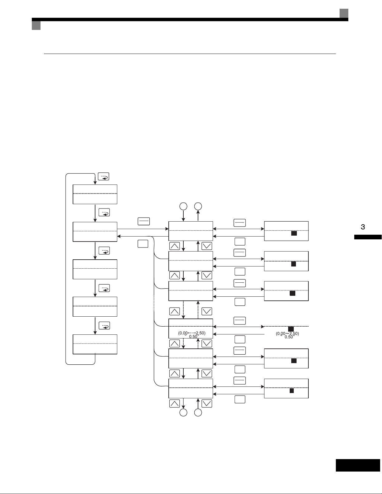
Drive Mode Indicators
Quick Programming Mode
In quick programming mode, the parameters required for Drive trial operation can be monitored and set.
Parameters can be changed from the setting displays. Use the Increment, Decrement, and Shift/RESET Keys
to change the frequency. The user parameter will be written and the monitor display will be returned to when
the DATA/ENTER Key is pressed after changing the setting.
Refer to Chapter 5 User Parameters for details on the parameters displayed in quick programming mode.
Example Operations
Key operations in quick programming mode are shown in the following figure.
Mode Selection Display
MENU
-DRIVE-
** Main Menu **
Operation
MENU
-QUICK-
** Main Menu **
Quick Setting
MENU
-ADV-
** Main Menu **
Programming
MENU
-VERIFY-
** Main Menu **
Modified Consts
MENU
-A.TUNE-
** Main Menu **
Auto-Tuning
DATA
ENTER
ESC
Monitor Display
A B
-QUICK-
Control Method
A1-02=2 *2*
Open Loop Vector
-QUICK-
Reference Source
b1-01=1 *1*
Terminals
-QUICK-
Run Source
b1-02=1 *1*
Terminals
-QUICK-
Terminal AM Gain
H4-05=0.50
-QUICK-
MOL Fault Select
L1-01=1 *1*
Std Fan Cooled
-QUICK-
StallP Decel Sel
L3-04=1 *1*
Enabled
Frequency Setting Display
DATA
ENTER
ESC
DATA
ENTER
-QUICK-
Control Method
A1-02= 2 *2*
Open Loop Vector
-QUICK-
Reference Source
b1-01= 1 *1*
ESC
DATA
ENTER
-QUICK-
Run Source
b1-02= 1 *1*
ESC
DATA
ENTER
-QUICK-
Terminal AM Gain
H4-05= 0 .50
ESC
DATA
ENTER
ESC
DATA
ENTER
-QUICK-
MOL Fault Select
L1-01= 1 *1*
Std Fan Cooled
-QUICK-
StallP Decel Sel
L3-04= 1 *1*
ESC
Terminals
Terminals
Enabled
A B
Fig 3.3 Operations in Quick Programming Mode
3-9
Page 83
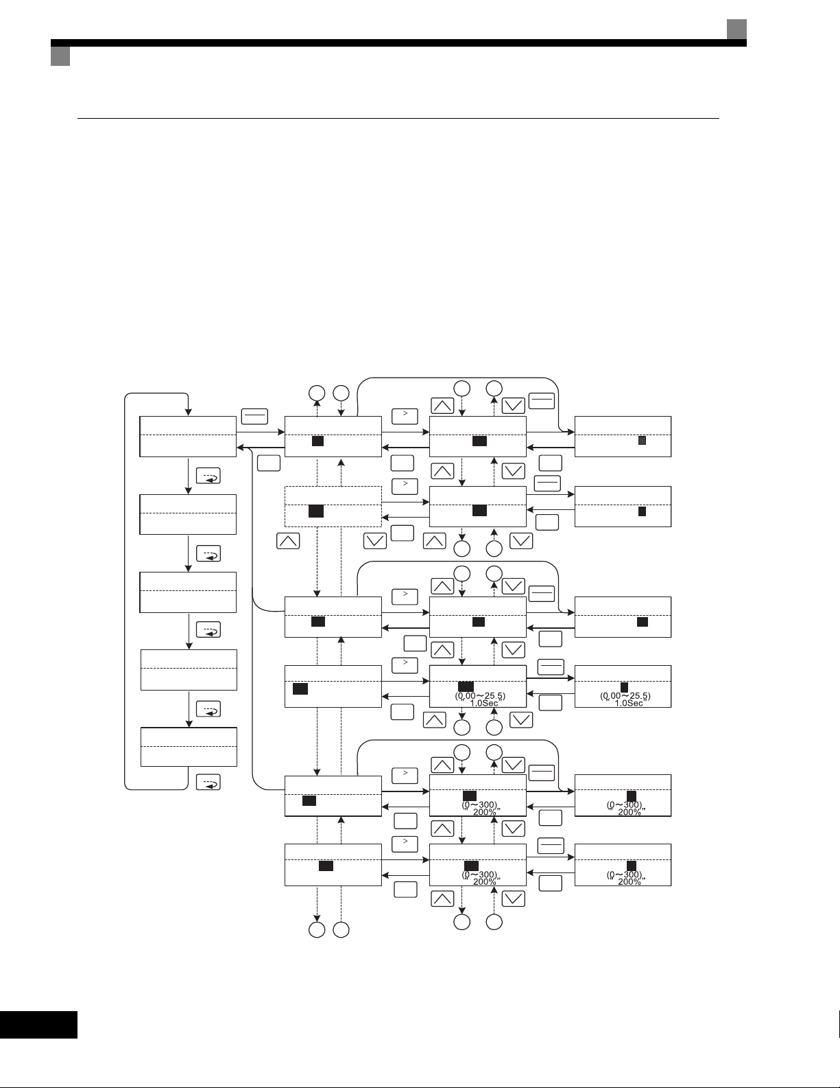
Advanced Programming Mode
In advanced programming mode, all Drive parameters can be monitored and set.
Parameters can be changed from the setting displays. Use the Increment, Decrement, and Shift/RESET Keys
to change the frequency. The user parameter will be written and the monitor display will be returned to when
the DATA/ENTER Key is pressed after changing the setting.
Refer to Chapter 5 User Parameters for details on the parameters.
Example Operations
Key operations in advanced programming mode are shown in the following figure.
Monitor Display Setting DisplayMode Selection Display
-ADV-
** Main Menu **
Programming
-VERIFY-
** Main Menu **
Modified Consts
-A.TUNE-
** Main Menu **
Auto-Tuning
-DRIVE-
** Main Menu **
Operation
-QUICK-
** Main Menu **
Quick Setting
MENU
MENU
MENU
MENU
MENU
DATA
ENTER
ESC
A B
-ADV-
Initialization
A1-00=1
Select Language
-ADV-
Initialization
A1-02 =2
Control Method
-ADV-
PID Control
b5-01=0
PID Mode
-ADV-
PID Control
b5 - 14= 1.0Sec
Fb los Det Time
-ADV-
Torque Limit
L7-01=200%
Fwd Torque Limit
-ADV-
Torque Limit
L7- 04= 200%
Fwd Torque Limit
RESET
ESC
RESET
ESC
RESET
RESET
ESC
RESET
ESC
RESET
ESC
ESC
1 2
-ADV-
Select Language
A1- 00 =0
English
-ADV-
Control Method
A1- 02 =2
Open Loop Vector
1 2
3 4
-ADV-
PID Mode
b5- 01 =0
Disabled
-ADV-
Fb los Det Time
b5- 14= 1.0Sec
3 4
5 6
-ADV-
Fwd Torque Limit
L7- 01= 200%
-ADV-
Fwd Torque Limit
L7- 04= 200%
DATA
ENTER
-ADV-
*1*
ESC
DATA
ENTER
*2*
ESC
DATA
ENTER
*0* *0*
ESC
DATA
ENTER
A1- 00= 0
English
-ADV-
Control Method
A1- 02= 2
Open Loop Vector
-ADV-
PID Mode
b5-01= 0
Disabled
-ADV-
Fb los Det Time
Select Language
*1*
*2*
b5-14=01.0Sec
ESC
DATA
ENTER
-ADV-
Fwd Torque Limit
L7-01= 2 00%
ESC
DATA
ENTER
-ADV-
Torq Lmt Rev Rgn
L7-04= 2 00%
ESC
3-10
A B
5 6
Fig 3.4 Operations in Advanced Programming Mode
Page 84
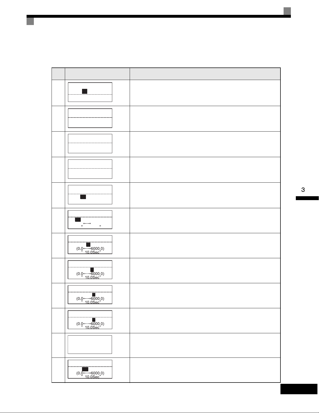
Setting User Parameters
Here, the procedure is shown to change C1-01 (Acceleration Time 1) from 10 s to 20 s.
Table 3.8 Setting User Parameters in Advanced Programming Mode
Drive Mode Indicators
Step
No.
1 Power supply turned ON.
2 MENU Key pressed to enter drive mode.
3 MENU Key pressed to enter quick programming mode.
4 MENU Key pressed to enter advanced programming mode.
5 DATA/ENTER pressed to access monitor display.
6 Increment or Decrement Key pressed to display C1-01 (Acceleration Time 1).
Digital Operator Display Description
-DRIVE-
Frequency Ref
Rdy
U1- 01=60.00Hz
U1-02=60.00Hz
U1-03=10.05A
-DRIVE-
** Main Menu **
Operation
-QUICK-
** Main Menu **
Quick Setting
-ADV-
** Main Menu **
Programming
-ADV-
Initialization
A1-00=1
Select Language
-ADV-
Accel Time 1
C1-00= 10.0Sec
(0.0 6000.0)
10.0Sec
-ADV-
Accel Time 1
7
8 Shift/RESET Key pressed to move the flashing digit to the right.
9 Increment Key pressed to change set value to 20.00 s.
10 DATA/ENTER Key pressed to enter the set data.
11
12 The monitor display for C1-01 returns.
C1-01= 0 010.0Sec
-ADV-
Accel Time 1
C1-01= 0 010.0Sec
-ADV-
Accel Time 1
C1-01= 00 10.0Sec
-ADV-
Accel Time 1
C1-01= 00 20.0Sec
-ADV-
Entry Accepted
-ADV-
Accel Time 1
C1- 01= 20.0Sec
DATA/ENTER Key pressed to access setting display. The setting of C1-01
(10.00) is displayed.
“Entry Accepted” is displayed for 1.0 s after the data setting has been confirmed with the DATA/ENTER Key.
3-11
Page 85

External Fault Setting Procedure
Examples of the Digital Operator displays that appear when setting an eternal fault for a multi-function
contact input in Advanced Programming Mode are shown in the following diagram.
Monitor Display Setting DisplayMode Selection Display
-ADV-
** Main Menu **
Programming
-VERIFY-
** Main Menu **
Modified Consts
-A.TUNE-
** Main Menu **
Auto-Tuning
-DRIVE-
** Main Menu **
Operation
-QUICK-
** Main Menu **
Quick Setting
DATA
ENTER
MENU
MENU
MENU
MENU
MENU
DATA
ENTER
ESC
A B
-ADV-
Digital Inputs
H1-01=24
Terminal S3 Sel
-ADV-
Digital Inputs
H1-02 =14
Terminal S4 Sel
-ADV-
Digital Inputs
H1-08 =08
Terminal S8 Sel
-ADV-
Digital Inputs
H2-01= 0
Term M1-M2 Sel
-ADV-
Pulse I/O Setup
H6-01= 0
Pulse Input Sel
A B
RESET
ESC
RESET
ESC
RESET
ESC
1 2
-ADV-
Terminal S3 Sel
H1- 01 =24
External Fault
"24"
-ADV-
Terminal S4 Sel
H1- 02 =14
Fault Reset
"14"
-ADV-
Terminal S8 Sel
H1- 08 =08
Ext BaseBlk N.O.
"08"
1 2
*24*
*14*
*08*
DATA
ENTER
ESC
3 4
-ADV-
Terminal S3 Sel
H1- 01= 24
NO/Always Det
Coast to Stop
-ADV-
Terminal S3 Sel
H1- 01= 25
NC/Always Det
Coast to Stop
-ADV-
Terminal S3 Sel
H1- 01= 26
NO/During RUN
Coast to Stop
-ADV-
Terminal S3 Sel
H1- 01= 27
NC/During RUN
Coast to Stop
-ADV-
Terminal S3 Sel
H1- 01= 2F
NC/During RUN
Alarm Only
*24*
*24*
*24*
*24*
*24*
3-12
3 4
Fig 3.5 External Fault Function Setting Example
Page 86
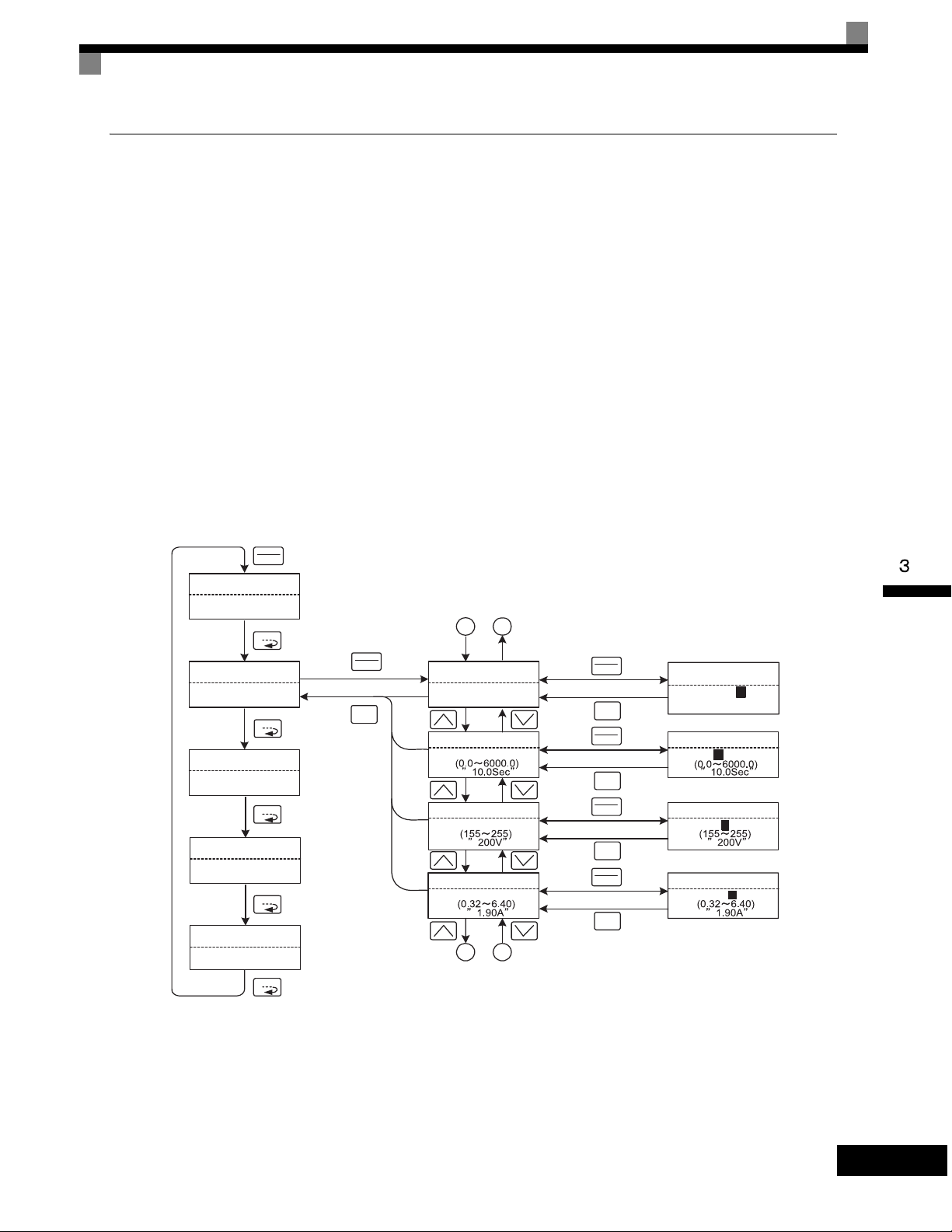
Drive Mode Indicators
Verify Mode
Verify mode is used to display any parameters that have been changed from their default settings in a
programming mode or by autotuning. “None” will be displayed if no settings have been changed.
Of the environment mode settings, only A1-02 will be displayed if it has been changed. Other environment
modes settings will not be displayed even if they have been changed from their default settings.
Even in verify mode, the same procedures can be used to change settings as are used in the programming
modes. Use the Increment, Decrement, and Shift/RESET Keys to change the frequency. The user parameter
will be written and the monitor display will be returned to when the DATA/ENTER Key is pressed after
changing the setting.
Example Operations
An example of key operations is given below for when the following settings have been changed from their
default settings: b1-01 (Reference Selection), C1-01 (Acceleration Time 1), E1-01 (Input Voltage Setting), and
E2-01 (Motor Rated Current).
-ADV-
** Main Menu **
Programming
-VERIFY-
** Main Menu **
Modified Consts
-A.TUNE-
** Main Menu **
Auto-Tuning
-DRIVE-
** Main Menu **
Operation
-QUICK-
** Main Menu **
Quick Setting
DATA
ENTER
MENU
MENU
MENU
MENU
MENU
DATA
ENTER
ESC
Monitor Display Setting DisplayMode Selection Display
A B
-VERIFY-
Reference Source
b1-01=0
-VERIFY-
Accel Time 1
C1-01=200.0Sec
-VERIFY-
Input Voltage
Terminals
"1"
*0*
E1-01=200VAC
-VERIFY-
Motor Rated FLA
E2-01=2.00A
A B
DATA
ENTER
ESC
DATA
ENTER
ESC
DATA
ENTER
ESC
DATA
ENTER
ESC
-VERIFY-
Reference Source
b1-01= 0
-VERIFY-
Accel Time 1
C1-01=0200.0Sec
-VERIFY-
Input Voltage
Terminals
"1"
*0*
E1-01= 200VAC
-VERIFY-
Motor Rated FLA
E2-01= 2.00A
Fig 3.6 Operations in Verify Mode
3-13
Page 87

Autotuning Mode
Autotuning automatically tunes and sets the required motor parameters when operating in the vector control
modes. Always perform autotuning before starting operation.
When V/f control has been selected, stationary autotuning for only line-to-line resistance can be selected.
When the motor cannot be disconnected from the load, perform stationary autotuning. Contact your Yaskawa
representatives to set motor parameters by calculation.
The Drive's autotuning function automatically determines the motor parameters, while a servo system's autotuning function determines the size of a load, the drives autotuning functions are fundamentally different. The
default setting of the Drive is for open-loop vector control 1.
Example of Operation
Set the motor output power (in kW), rated voltage, rated current, rated frequency, rated speed, and number of
poles specified on the nameplate on the motor and then press the RUN Key. The motor is automatically run
and the motor parameters measured based on these settings and autotuning will be set.
Always set the above items. Autotuning cannot be started otherwise, e.g., it cannot be started from the motor
rated voltage display.
Parameters can be changed from the setting displays. Use the Increment, Decrement, and Shift/RESET Keys
to change the frequency. The user parameter will be written and the monitor display will be returned to when
the DATA/ENTER Key is pressed after changing the setting.
The following example shows autotuning for open-loop vector control while operating the motor without
switching to motor 2.
3-14
Page 88
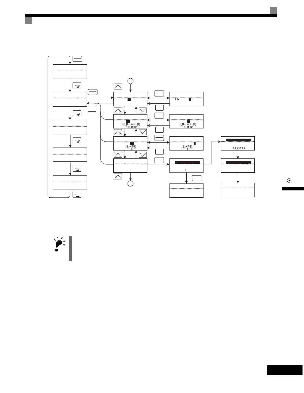
Drive Mode Indicators
T
Monitor Display Setting DisplayMode Selection Display
DATA
ENTER
-VERIFY-
** Main Menu **
Modified Consts
MENU
DATA
-A.TUNE-
** Main Menu **
ENTER
Auto-Tuning
ESC
-DRIVE-
** Main Menu **
MENU
Operation
MENU
-QUICK-
** Main Menu **
Quick Setting
MENU
-ADV-
** Main Menu **
Programming
MENU
* TUn10 will be displayed during rotational autotuning and TUn11 will be displayed during stationary autotuning. The DRIVE indicator will light when
autotuning starts.
A
-A.TUNE-
Tuning Mode Sel
T1- 01 =0 *0*
Standard Tuning
"0"
-A.TUNE-
Rated Frequency
T1- 05 = 60.0Hz
-A.TUNE-
Number of Poles
T1- 06 = 4
-A.TUNE-
Auto-Tuning
0.0Hz/0.0A
Tuning Ready ?
Press RUN key
A
DATA
ENTER
ESC
DATA
ENTER
ESC
DATA
ENTER
ESC
Rdy
RUN
The display will
automatically
change depending
on the status of
autotuning.
-A.TUNE-
Tuning Mode Sel
01 = 0 *0*
Standard Tuning
"0"
-A.TUNE-
Rated Frequency
T1- 05 = 0 60.0Hz
-A.TUNE-
Number of Poles
T1- 06 = 04
-A.TUNE-
Tune Proceeding
48.0Hz/10.5A
START GOAL
STOP
-A.TUNE-
Tune Aborted
STOP key
-A.TUNE-
Tune Proceeding
48.0Hz/10.5A
START GOAL
-A.TUNE-
Tune Proceeding
Tune Successful
-A.TUNE-
Tune Successful
IMPORTAN
Fig 3.7 Operation in Autotuning Mode
The setting displays in for autotuning depend on the control mode (V/f, V/f with PG, open-loop vector 1, openloop vector 2, or flux vector). If a fault occurs during autotuning, refer to Chapter 1 Troubleshooting.
3-15
Page 89

3-16
Page 90

4
Trial Operation
This chapter describes the procedures for trial operation of the Drive and provides an example
of trial operation.
Trial Operation Procedure............................................4-2
Trial Operation Procedures..........................................4-3
Adjustment Suggestions ............................................4-17
Page 91

Trial Operation Procedure
Perform trial operation according to the following flowchart.
START
Installation
Wiring
Select operating
method.
(Default: A1-02 = 0)
Settings according
to control mode
Set power supply voltage.
Turn ON power.
Confirm status.
Basic settings
(Quick programming mode)
V/f control?
YES
V/f
PG?
Set E1-03.
V/f default: 200 V/60 Hz(400 V/60 Hz)
Motor cable over
50 m or heavy load possibly
causing motor to stall or
overload?
*1
Vector (A1-02 = 2, 3, or 4)*5
V/f with PG
(A1-02 = 1)
YES
Set E1-03, E2-04, and F1-01.
V/f default: 200 V/60 Hz (400 V/60 Hz)
motor during autotuning?
*2
OK to operate
NO
*3
4-2
NO
Application settings
(Advanced programming mode)
No-load operation
Loaded operation
Optimum adjustments and
constant settings
Check/record constants.
END
Fig 4.1 Trial Operation Flowchart
YES
Stationary autotuning for
line-to-line resistance only
*1 Set for 400 V Class Inverter for 55 kW or more.
*2 If there is a reduction gear between the motor and PG, set
the reduction ratio in F1-12 and F1-13 in advanced
programming mode.
*3 Use rotational autotuning to increase autotuning accuracy
whenever it is okay for the motor to be operated.
*4 If the motor cable changes to 50 m or longer for the actual
installation, perform stationary autotuning for the line-to-line
resistance only on-site.
*5 The default control mode is open-loop vector control 2
(A1-02 = 2).
*4
Rotational autotuning
*6
*6 If the maximum output frequency and base frequency
are different, set the maximum output frequency (E1-
04) after autotuning.
Stationary autotuning
*6
Page 92

Trial Operation Procedures
Trial Operation Procedures
The procedure for the trial operate is described in order in this section.
Setting the Power Supply Voltage Jumper (380-480 V Class Drives of 55
kW or Higher)
Set the power supply voltage jumper after setting E1-01 (Input Voltage Setting) for 380-480 V Class Drives
of 55 kW or higher. Insert the jumper into the voltage connector nearest to the actual power supply
voltage.
The jumper is factory-set to 440 V when shipped. If the power supply voltage is not 440 V, use the
following procedure to change the setting.
1. Turn OFF the power supply and wait for at least 5 minutes.
2. Confirm that the CHARGE indicator has gone out.
3. Remove the terminal cover.
4. Insert the jumper at the position for the voltage supplied to the Drive (see Fig 4.2).
5. Return the terminal cover to its original position.
200-240 V class power supply
380-480V class power supply
Power supply input terminals
Fig 4.2 Power Supply Voltage Jumper
Power ON
Confirm all of the following items and then turn ON the power supply.
• Check that the power supply is of the correct voltage.
200-240 V class: 3-phase 200 to 240 Vdc, 50/60Hz
380-480 V class: 3-phase 380 to 480 Vdc, 50/60Hz
• Make sure that the motor output terminals (U/T1, V/T2, W/T3) and the motor are connected correctly.
• Make sure that the Drive control circuit terminal and the control device are wired correctly.
• Set all Drive control circuit terminals to OFF.
• When using a PG Speed Control Card, make sure that it is wired correctly.
• Make sure that the motor is not connected to the mechanical system (no-load status)
Power tab
Jumper (factory-set position)
CHARGE indicator
4-3
Page 93

Checking the Display Status
01
If the Digital Operator's display at the time the power is connected is normal, it will read as follows:
Display for normal operation
-DRIVE-
-DRIVE-
Frequency Ref
Frequency Ref
U1- 01= 60.0 0Hz
U1-01= 0 0 0.0 0Hz
U1-02=60.00Hz
U1-03=10.05A
Rdy
The frequency reference monitor is displayed in the data display section.
When an fault has occurred, the details of the fault will be displayed instead of the above display. In that case,
refer to Chapter 7 Troubleshooting. The following display is an example of a display for faulty operation.
Display for fault operation
-DRIVE-
Frequency Ref
UV
DC Bus Undervolt
The display will differ depending on the
type of fault.
A low voltage alarm is shown at left.
4-4
Page 94

Trial Operation Procedures
Basic Settings
Switch to the quick programming mode (“QUICK” will be displayed on the LCD screen) and then set the following user parameters. Refer to Chapter 3 Digital Operator and Modes for Digital Operator operating proce-
dures and to Chapter 5 User Parameters and Chapter 6 Parameter Settings by Function for details on the user
parameters.
Parameters that must be set are listed in Table 4.1 and those that are set according to the application are listed
in Table 4.2.
Table 4.1 Parameters that Must Be Set
Parameter
Number
A1-02
b1-01
b1-02
C1-01
C1-02
E1-01
Name Description
Set the control method for the Drive.
0: V/f control
Control method
selection
Reference selection
Operation
method selection
Acceleration time 1Set the acceleration time in seconds for the output
Deceleration time 1Set the deceleration time in seconds for the output
Input voltage setting
1: V/f control with PG
2: Open-loop vector control 1
3: Flux vector
4: Open-loop vector control 2
Set the frequency reference input method.
0: Digital Operator
1: Control circuit terminal (analog input)
2: MODBUS communications
3: Option Card
4: Pulse train input
Set the run command input method.
0: Digital Operator
1: Control circuit terminal (sequence input)
2: MODBUS communications
3: Option Card
frequency to climb from 0% to 100%.
frequency to fall from 100% to 0%.
Set the Drive's nominal input voltage in volts.
Setting
Range
0 to 4 2
0 to 4 1
0 to 3 1
0.0 to 6000.0 10.0 s
0.0 to 6000.0 10.0 s
155 to 255 V
(200-240 V
class)
310 to 510 V
(380-480 V
class)
Factory
Setting
200 V
(200-240
V class)
400 V
(380-480
V class)
E2-01
L1-01
Motor rated current
Motor protection
selection
Set the motor rated current.
Set to enable or disable the motor overload protection function using the electronic thermal relay.
0: Disabled
1: General motor protection
2: Drive motor protection
3: Vector motor protection
10% to 200%
of Drive's
rated current
0 to 3 1
Setting for
general-
purpose
motor of
same
capacity
as Drive
4-5
Page 95

Table 4.2 Parameters that Are Set as Required
Parameter
Number
b1-03
C6-02
C6-11
d1-01 to
d1-04 and
d1-17
Name Description
Select stopping method when stop command is
sent.
Stopping method
selection
Carrier frequency selection
Carrier frequency selection
for open-loop
vector control 2
Frequency references 1 to 4 and
jog frequency reference
0: Deceleration to stop
1: Coast to stop
2: DC braking stop
3: Coast to stop with timer
The carrier frequency is set low if the motor cable
is 50 m or longer or to reduce radio noise or leak-
age current.
Set the required speed references for multi-step
speed operation or jogging.
Setting
Range
0 to 3 0
1 to F
1 to 4
0.00 to
400.00 Hz
Factory
Setting
Depends
on capac-
ity, voltage, and
control
mode.
Depends
on kVA
setting.
d1-01 to
d1-04:
0.00Hz
d1-17:
6.00Hz
H4-02
and H4-
05
L3-04
FM and AM terminal output gain
Stall prevention
selection during
deceleration
Adjust when an instrument is connected to the FM
or AM terminal.
If using the dynamic brake option (braking resistor, Braking Resistor Units, and Braking Units), be
sure to set parameter L3-04 to 0 (disabled) or 3
(enabled with braking resistor).
0.0 to 1000.0
0 to 3 1
H4-02:
100%
H4-05:
50%
4-6
Page 96
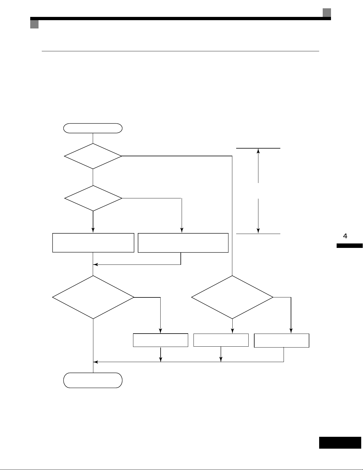
Trial Operation Procedures
Settings for the Control Methods
Autotuning methods depend on the control method set for the Drive. Make the settings required by the control
method.
Overview of Settings
Make the required settings in quick programming mode and autotuning mode according to the following flowchart.
START
NO
V/f control?
Vector (A1-02 = 2, 3, or 4)*3
YES
V/f
NO
(Default: A1-02 = 0)
Set E1-03.
V/f default: 200 V/60 Hz(400 V/60 Hz)
Motor cable over
50 m or heavy load possibly
causing motor to stall
(A1-02 = 0 or 1)
PG?
or overload?
NO
YES
(A1-02 = 1)
Set E1-03, E2-04, and F1-01.
V/f default: 200 V/60 Hz(400 V/60 Hz)
YES
Stationary autotuning for
line-to-line resistance only
motor during autotuning?*1
Rotational autotuning*4
*2
OK to operate
YES
Control mode selection
NO
Stationary autotuning*4
END
Note If the motor cable changes to 50 m or longer for the actual installation, perform stationary autotuning for the line-to-line resistance only on-site.
* 1. Use rotational autotuning to increase autotuning accuracy whenever it is okay for the motor to be operated. Always perform rotational autotuning when
using open-loop vector control 2.
* 2. If there is a reduction gear between the motor and PG, set the reduction ratio in F1-12 and F1-13.
* 3. The default setting of the Drive is for open-loop vector control 1 (A1-02 = 2).
* 4. If the maximum output frequency and base frequency are different, set the maximum output frequency (E1-04) after autotuning.
Fig 4.3 Settings According to the Control Method
4-7
Page 97

Setting the Control Method
Any of the following five control methods can be set.
Control Mode
V/f control A1-02 = 0 Voltage/frequency ratio fixed control
Parameter
Setting
Basic Control Main Applications
Variable speed control, particularly
control of multiple motors with one
Drive and replacing existing drives
V/f control with PG A1-02 = 1
Open-loop vector
control 1
Flux vector control A1-02 = 3 Flux vector control
Open-loop vector
control 2
Note With vector control, the motor and Drive must be connected 1:1. The motor capacity for which stable control is possible is 50% to 100% of the capacity
of the Drive.
A1-02 = 2
(factory setting)
A1-02 = 4
Voltage/frequency ratio fixed control
with speed compensation using a PG
Current vector control without a PG
Current vector control without a PG
with an ASR (speed controller)
(Always perform rotational autotuning.)
Applications requiring high-precision
speed control using a PG on the
machine side
Variable speed control, applications
requiring speed and torque accuracy
using vector control without a PG
Very high-performance control with a
PG (simple servo drives, high-precision speed control, torque control, and
torque limiting)
Very high-performance control without a PG (torque control without a PG,
torque limiting, applications requiring
a 1:200 speed control range without a
PG)
PG Control without PG (A1-02 = 0)
• Set either one of the fixed patterns (0 to E) in E1-03 (V/f Pattern Selection) or set F in E1-03 to specify a
user-set pattern as required for the motor and load characteristics in E1-04 to E1-13 in advanced programming mode.
Simple operation of a general-purpose
motor at 50Hz:
E1-03 = 0
Simple operation of a general-purpose
motor at 60Hz:
E1-03 = F (default) or 1
If E1-03 = F, the default setting in the user setting from
E1-04 to E1-13 are for 60Hz
4-8
• Perform stationary autotuning for the line-to-line resistance only if the motor cable is 50 m or longer for
the actual installation or the load is heavy enough to produce stalling. Refer to the following section on
Autotuning for details on stationary autotuning.
V/f Control with PG (A1-02 = 1)
• Set either one of the fixed patterns (0 to E) in E1-03 (V/f Pattern Selection) or set F in E1-03 to specify a
user-set pattern as required for the motor and load characteristics in E1-04 to E1-13 in advanced programming mode.
Simple operation of a general-purpose
motor at 50Hz:
E1-03 = 0
Simple operation of a general-purpose
motor at 60Hz:
E1-03 = F (default) or 1
If E1-03 = F, the default setting in the user setting from
E1-04 to E1-13 are for 60Hz
• Set the number of motor poles in E2-04 (Number of Motor Poles)
Page 98

Trial Operation Procedures
• Set the number of rotations per pulse in F1-01 (PG Constant). If there is a reduction gear between the
motor and PG, set the reduction ratio in F1-12 and F1-13 in advanced programming mode.
• Perform stationary autotuning for the line-to-line resistance only if the motor cable is 50 m or longer for
the actual installation or the load is heavy enough to produce stalling. Refer to the following section on
Autotuning for details on stationary autotuning.
Open-loop Vector Control 1 (A1-02 = 2)
Perform autotuning. If the motor can be operated, perform rotational autotuning. If the motor cannot be operated, perform stationary autotuning. Refer to the following section on Autotuning for details on autotuning.
Flux Vector Control (A1-02 = 3)
Perform autotuning. If the motor can be operated, perform rotational autotuning. If the motor cannot be operated, perform stationary autotuning. Refer to the following section on Autotuning for details on autotuning.
Open-loop Vector Control 2 (A1-02 = 4)
Perform autotuning. Be sure to perform rotational autotuning. Refer to the following section on Autotuning for
details on autotuning.
Autotuning
Use the following procedure to perform autotuning to automatically set motor parameters when using the vector control method, when the cable length is long, etc.
Setting the Autotuning Mode
One of the following three autotuning modes can be set.
• Rotational autotuning
• Stationary autotuning
• Stationary autotuning for line-to-line resistance only
Always confirm the precautions before autotuning before performing autotuning.
Rotational Autotuning (T1-01 = 0)
Rotational autotuning is used only for open-vector control. Set T1-01 to 0, input the data from the nameplate,
and then press the RUN Key on the Digital Operator. The Drive will stop the motor for approximately
1 minute and then set the required motor parameters automatically while operating the motor for approximately 1 minute.
Stationary Autotuning (T1-01 = 1)
Stationary autotuning is used for open-vector control or flux vector control. Set T1-01 to 1, input the data from
the nameplate, and then press the RUN Key on the Digital Operator. The Drive will supply power to the stationary motor for approximately 1 minute and some of the motor parameters will be set automatically. The
remaining motor parameters will be set automatically the first time operation is started in drive mode.
4-9
Page 99
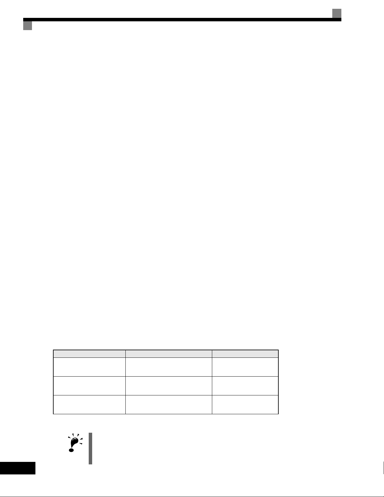
Stationary Autotuning for Line-to-Line Resistance Only (T1-01 = 2)
T
Stationary autotuning for line-to-line resistance only can be used in any control method. This is the only autotuning possible for V/f control and V/f control with PG modes.
Autotuning can be used to prevent control errors when the motor cable is long (50 m or longer) or the cable
length has changed since installation or when the motor and Drive have different capacities.
Set T1-01 to 2 for open-loop vector control, and then press the RUN Key on the Digital Operator. The Drive
will supply power to the stationary motor for approximately 20 seconds and the Motor Line-to-Line Resistance (E2-05) and cable resistance will be automatically measured.
Precautions Before Using Autotuning
Read the following precautions before using autotuning.
• Autotuning the Drive is fundamentally different from autotuning the servo system. Drive autotuning auto-
matically adjusts parameters according to detected motor parameters, whereas servo system autotuning
adjusts parameters according to the detected size of the load.
• When speed precision or torque precision is required at high speeds (i.e., 90% of the rated speed or higher),
use a motor with a rated voltage that is 20 V less than the input power supply voltage of the Drive for 200240V-class Drives and 40 V less for 380-480V-class Drives. If the rated voltage of the motor is the same as
the input power supply voltage, the voltage output from the Drive will be unstable at high speeds and sufficient performance will not be possible.
• Use stationary autotuning whenever performing autotuning for a motor that is connected to a load.
• Use rotational autotuning whenever performing autotuning for a motor that has fixed output characteris-
tics, when high precision is required, or for a motor that is not connected to a load.
• If rotational autotuning is performed for a motor connected to a load, the motor parameters will not be
found accurately and the motor may exhibit abnormal operation. Never perform rotational autotuning for a
motor connected to a load.
• If the wiring between the Drive and motor changes by 50 m or more between autotuning and motor instal-
lation, perform stationary autotuning for line-to-line resistance only.
• If the motor cable is long (50 m or longer), perform stationary autotuning for line-to-line resistance only
even when using V/f control.
• The status of the multi-function inputs and multi-function outputs will be as shown in the following table
during autotuning. When performing autotuning with the motor connected to a load, be sure that the holding brake is not applied during autotuning, especially for conveyor systems or similar equipment.
4-10
Tuning Mode Multi-function Inputs Multi-function Outputs
Rotational autotuning Do not function.
Stationary autotuning Do not function.
Stationary autotuning for line-
to-line resistance only
• To cancel autotuning, always use the STOP Key on the Digital Operator.
1. Power will be supplied to the motor when stationary autotuning is performed even though the motor
will not turn. Do not touch the motor until autotuning has been completed.
IMPORTAN
2. When performing stationary autotuning connected to a conveyor or other machine, ensure that the
holding brake is not activated during autotuning.
Do not function.
Same as during normal
operation
Maintain same status as
when autotuning is started.
Maintain same status as
when autotuning is started.
Page 100
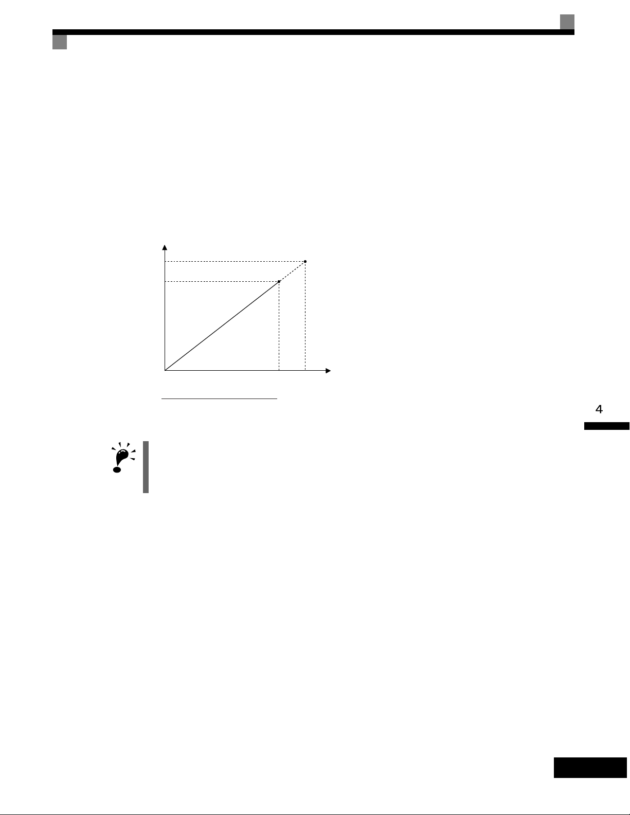
Trial Operation Procedures
T
Precautions for Rotational and Stationary Autotuning
Lower the base voltage based on Fig 4.4 to prevent saturation of the Drive’s output voltage when the rated
voltage of the motor is higher than the voltage of the power supply to the Drive. Use the following procedure
to perform autotuning.
1. Input the voltage of the input power supply to T1-03 (Motor rated voltage).
2. Input the results of the following formula to T1-05 (Motor base frequency):
(Base frequency from the motor’s nameplate × setting of T1-03)/(Rated voltage from motor’s nameplate)
3. Perform autotuning.
After completing autotuning, set E1-04 (Max. output frequency) to the base frequency from the motor’s nameplate.
Output voltage
Rated voltage from
motor nameplate
T1-03
0
Base frequency
from motor nameplate
Rated voltage from motor nameplate
×T1-03
Base frequency
from motor nameplate
Output frequency
Fig 4.4 Motor Base Frequency and Drive Input Voltage Setting
1. When speed precision is required at high speeds (i.e., 90% of the rated speed or higher), set T1-03 (Motor
rated voltage) to the input power supply voltage × 0.9.
IMPORTAN
2. When operating at high speeds (i.e., 90% of the rated speed or higher), the output current will increase as
the input power supply voltage is reduced. Be sure to provide sufficient margin in the Drive current.
Precautions after Rotational and Stationary Autotuning
If the maximum output frequency and base frequency are different, set the maximum output frequency (E1-
04) after autotuning.
4-11
 Loading...