

Page 1

G5 - HHP Drive
Technical Manual
Compact High-Capacity Inverter Panels
400-V Class: 200-800 kW (320 to 1200 kVA)
575-V Class: 300-1200 kW (400 to 1500 kVA)
Models: CIMR-G5A Document Number: TM.G5HHP.01
Page 2

Preface
Preface
Thank you for purchasing the compact High-capacity VARISPEED-616G5 Inverter Panels with neu-
rovector control.
This manual is designed to ensure correct and suitable application of the High-capacity VA-
RISPEED-616G5 Inverter Panels. Read this manual before attempting to install, operate, maintain,
or inspect an Inverter and keep this manual in a safe, convenient location for future reference. Be sure
you understand all precautions and safety information before attempting application.
i
Page 3

Safety Information
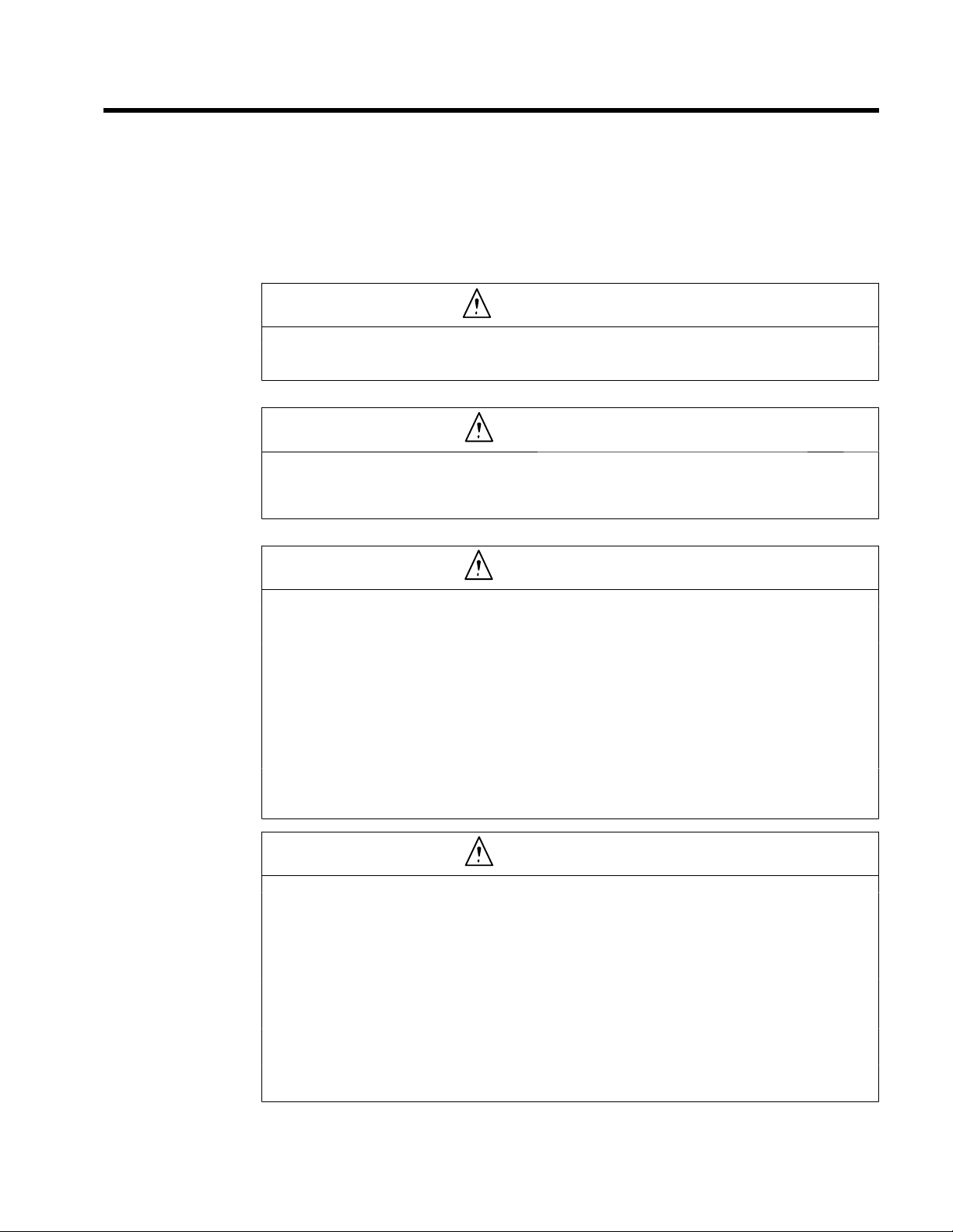
The following conventions are used to indicate precautions in this manual. Failure to heed precautions provided in
this manual can result in seriousor possibly even fatalinjury or damage to the products or to related equipmentand
systems.
WARNING Indicates precautions that, if not heeded, could possibly result in loss of life or
!
CAUTION Indicates precautions that, if not heeded, could result in relatively serious or minor
!
The warning symbols for ISO and JIS standards are different, as shown below.
The ISO symbol is used in this manual.
Both of these symbols appearon warning labels on Yaskawa products. Please abide by thesewarning labelsregard-
less of which symbol is used.
serious injury.
injury, damage to the product, or faulty operation.
ISO JIS
Yaskawa, 1998
All rights reserved. No part of this publication may be reproduced, stored in a retrieval system, or transmitted,
in any form, or by any means, mechanical, electronic, photocopying, recording, or otherwise, without the prior
written permission of Yaskawa. No patent liability is assumed with respect to the use of the information contained
herein. Moreover, because Yaskawa is constantly striving to improve its high-quality products, the information
contained in this manual is subject to change without notice. Every precaution has been taken in the preparation
of this manual. Nevertheless, Yaskawa assumes no responsibility for errors or omissions. Neither is any liability
assumed for damages resulting from the use of the information contained in this publication.
ii
Page 4

Visual Aids
Visual Aids
The following aids are used to indicate certain types of information for easier reference.
AEXAMPLE"
INFO
IMPORTANT
Indicates application examples.
Indicates supplemental information.
Indicates important information that should be memorized.
iii
Page 5

General Precautions
D The diagrams in this manual may be indicated without covers or safety shields to show de-
tails. Be sure to restore covers or shieldsbefore operating the Units and run the Units according to the instructions described in this manual.
D Any illustrations, photographs, or examples used in this manual are provided as examples
only and may not apply to all products to which this manual is applicable.
D The products and specifications described in this manual or the content and presentation of
the manual may be changed without notice to improve the product and/or the manual.
D When ordering a new copy of the manual due to damage or loss, contact your Yaskawarepre-
sentatives or the nearest Yaskawa sales office and provide the manual number shown on the
front cover.
D If nameplates become warn or damaged, order new ones from your Yaskawa representatives
or the nearest Yaskawa sales office.
iv
Page 6
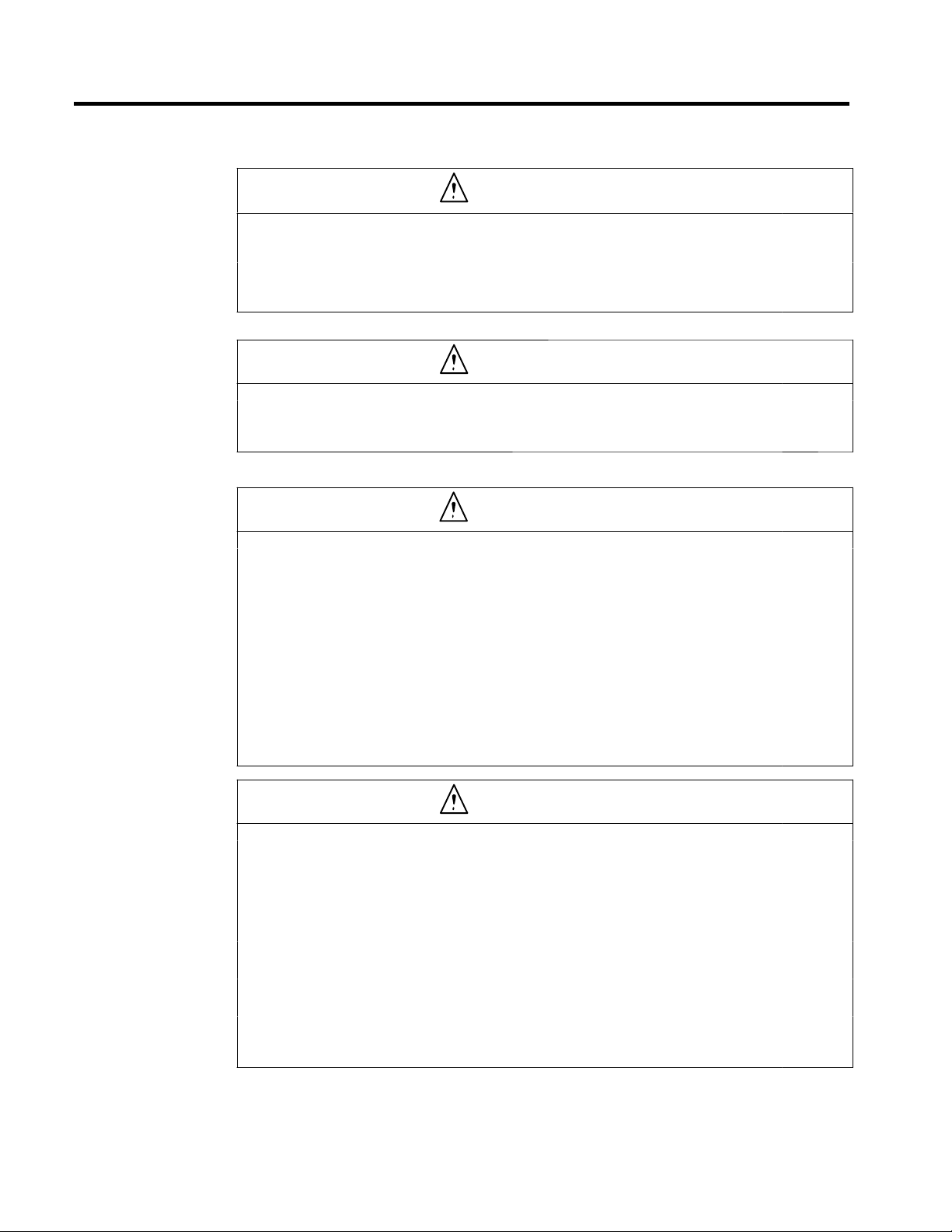
Safety Precautions
J Confirmations upon Delivery
D Never install an Inverter Panel that is damaged or missing components.
Doing so can result in injury.
J Transportation
D Crane operation must be performed only by an authorized person qualified to operate
cranes.
Otherwise, injury or damage caused by dropping lifted objects.
J Wiring
Safety Precautions
CAUTION
Page
2-2
CAUTION
Page
2-4
WARNING
D Always turn OFF the input power supply before wiring terminals.
Otherwise, an electric shock or fire can occur.
D Wiring must be performed by an authorized person qualified in electrical work.
Otherwise, an electric shock or fire can occur.
D Be sure to ground the ground terminal.
(400-V and 575-V Class Inverters: Ground to 10 Ω or less)
Otherwise, an electric shock or fire can occur.
D Always check the operation of any emergency stop circuits after they are wired.
Otherwise, there is the possibility of injury. (Wiring is the responsibility of the user.)
D Never touch the output terminals directly with your hands or allow the output lines to
come into contact with the Inverter Panel casing. Never short the output circuits.
Otherwise, electrical shock or grounding can occur.
CAUTION
D Check to be sure that the voltage of the main AC power supply satisfies the rated volt-
age of the Inverter Panel.
Injury or fire can occur if the voltage is not correct.
D Do not perform voltage withstand tests on the Inverter Panel.
Voltage withstand test can damage semiconductor elements and other components.
D Connect Braking Resistor Units and Braking Units as shown in the I/O wiring exam-
ples.
Otherwise, a fire can occur.
D Tighten all terminal screws to the specified tightening torque.
Otherwise, a fire may occur.
D Do not connect AC power to output terminals U, V, and W.
The internal Inverter Module will be damaged if voltage is applied to the output terminals.
Page
3-2
3-2
3-2
3-2
3-2
Page
3-2
3-2
3-2
3-2
3-2
v
Page 7
CAUTION
D Do not connect phase-advancing capacitors or LC/RC noise filters to the output cir-
cuits.
The Inverter panel can be damaged or internal parts burnt if these devices are connected.
D Do not connect electromagnetic switches or contactors to the output circuits.
If a load is connected while the InverterPanel is operating, surgecurrentwill cause the overcurrent protection circuit to operate.
J Setting User Constants
CAUTION
D Disconnect the load (machine, device) from the motor before autotuning.
The motor may turn, possibly resulting in injury or damage to equipment. Also, motor constants
cannot be correctly set with the motor attached to a load.
J Trial Operation
WARNING
D Check to be sure that the front door is closed before turning ON the power supply. Do
not open the front door during operation.
An electric shock may occur if the front door is open when power is ON.
D Do not come close to the machine when the fault reset function is used. If the alarm is
cleared,the machine may startmoving suddenly.Also, design the machine so that human safety is ensured even when it is restarted.
Injury may occur.
D Provide a separate emergency stop switch; the Digital Operator STOP Key is valid
only when its function is set.
Injury may occur.
D Reset alarms only after confirming that the RUN signal is OFF. If an alarm is reset with
the RUN signal turned ON, the machine may suddenly start.
Injury may occur.
3-2
3-2
Page
4-33
Page
5-2
5-2
5-2
5-2
CAUTION
D Don’t touch the radiation fins (heat sink), braking resistor, or Braking Resistor Unit.
These can become very hot.
Otherwise, a burn injury may occur.
D Be sure that the motor and machine is within the applicable ranges before starting op-
eration.
Otherwise, an injury may occur.
D Provide a separate holding brake if necessary.
Otherwise, an injury may occur.
D Don’t check signals while the Inverter is running.
Otherwise, the equipment may be damaged.
D Be careful when changing Inverter Panel settings. The Inverter Panel is factory set to
suitable settings.
The equipment may be damaged is unsuitable settings are used.
vi
Page
5-2
5-2
5-2
5-2
5-2
Page 8

J Maintenance and Inspection
WARNING
D Do not touch the Inverter Panel terminals. Some of the terminals carry high voltages
and are extremely dangerous.
Touching the terminals can result in electric shock.
D Always have the protectivecover in place when power is being supplied to the Invert-
er. When attaching the cover, always turn OFF power to the Inverter through the
MCCB.
Doing so can result in electric shock.
D After turning OFF the main circuit power supply, wait until the CHARGE indicator light
goes out before performance maintenance or inspections.
The capacitor will remain charged and is dangerous.
D Maintenance, inspection, and replacement of parts must be performed only by autho-
rized personnel.
Remove all metal objects, such as watches and rings, before starting work. Always
use grounded tools.
Failure to heed these warning can result in electric shock.
D Before mounting or dismounting a Module, make sure that the main circuit and control
power supply have been turned OFF.
Not doing so can result in electric shock.
D Do not dismount a Module until the CHARGE lamp on the Module turns OFF after turn-
ing OFF the power supply.
An electric shock may occur is the Module is dismounted while still charged.
D Use special lifts for mounting or dismounting a Module.
Not doing so can result in injury.
D The Modules are heavy, and mounting or dismounting the Modules must be per-
formed by three workers: One to operate the lift and two others for mounting and dismounting the Modules.
Not doing so can result in injury
D Before disposing of a Module, open a hole in the heat sink attached to the Module to
purge gas.
Exposingthe heatsink to a high temperaturewithout opening a hole in the heat sinkcan resultin
explosion and injury.
Safety Precautions
Page
10 - 2
10 - 2
10 - 2
10 - 2
10 - 6
10 - 6
10 - 6
10 - 6
10 - 14
CAUTION
D A CMOS IC is used in the control board. Handle the control board and CMOS IC care-
fully. The CMOS IC can be destroyed by static electricity if touched directly.
The CMOS IC can be destroyed by static electricity if touched directly.
D Do not change the wiring, or remove connectors or the Digital Operator, during opera-
tion.
Performing this word during operation can result in personal injury.
J Others
WARNING
D Do not attempt to modify or alter the Inverter.
Alterations or modifications can result in electrical shock or injury.
vii
Page
10 - 2
10 - 2
Page 9
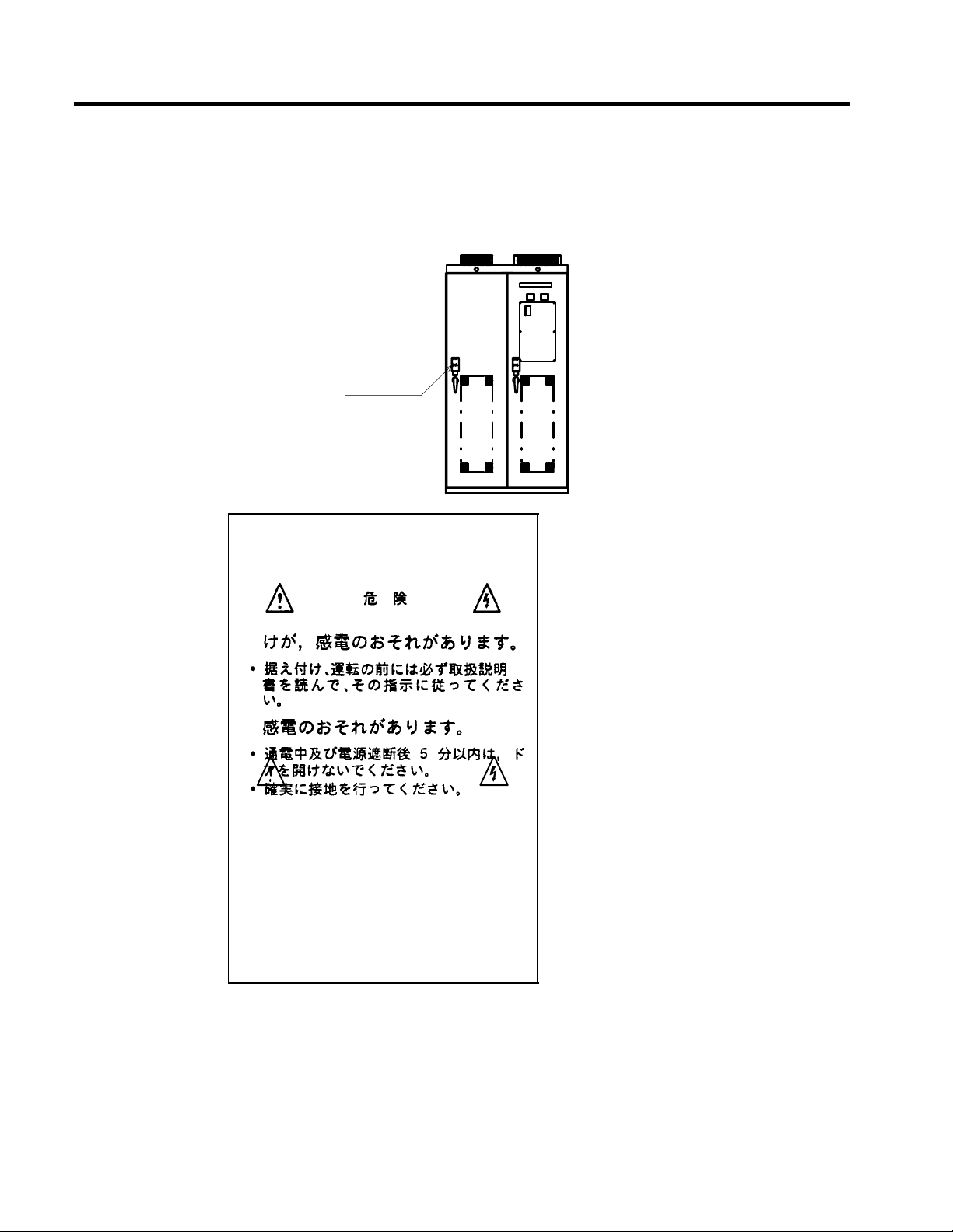
Warning Label Contents and Position
There is a warning label on the Inverter in the position shown in the following illustration. Always heed the warnings
given on this label.
Warning label
position
Warning Label Contents
The illustration shows a 400-V class (200-kW)
and a 575-V class (300-kW) Inverter.
May cause injury or electric
shock.
D Please follow the instructions in
the manual before installation or
operation.
D Disconnect all power before opening
the door of panel. Wait 5 minutes
until DC Bus capacitors discharge.
D Use proper grounding techniques.
Definition of Terms
The following definitions are used in this manual unless otherwise specified.
Inverter: Inverter Panel
Module: Inverter Module or Converter Module
WARNING
viii
Page 10
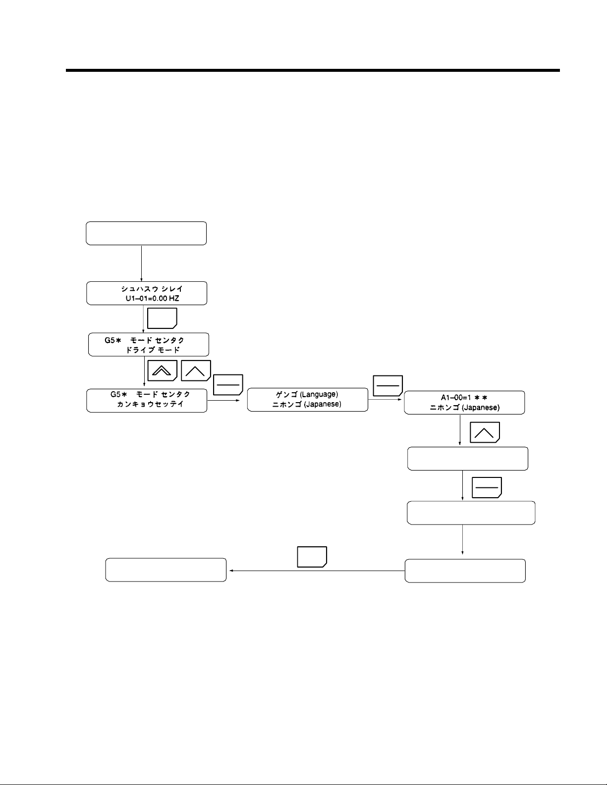
How to Change the Digital Operator Display from Japanese to English
How to Change the Digital Operator Display from Japanese to English
If the Digital Operator displays messages in Japanese, change to the English mode using the following
steps.
(This manual provides descriptions for the English mode.)
Power ON
MENU
* Main Menu *
Operation
DATA
ENTER
MENU
DATA
ENTER
A1--00=0
English
DATA
ENTER
Entry Accepted
Select language
English
ix
Page 11

CONTENTS
11 Introduction
12 Handling Inverters
13 Wiring
14 Setting User Constants
15 Trial Operation
16 Basic Operation
1
2
3
4
5
6
17 Advanced Operation
18 User Constants
19 Troubleshooting
10 Maintenance and Inspection
11 Specifications
12 Appendix
7
8
9
10
11
12
Page 12

Table of Contents
Table of Contents
Preface i.........................................................
Safety Information ii................................................
Visual Aids iii......................................................
General Precautions iv...............................................
Safety Precautions v................................................
Warning Label Contents and Position viii.................................
Definition of Terms viii...............................................
How to Change the Digital Operator Display from Japanese to English ix......
1 Introduction 1 - 1.........................................
1.1 Outline and Functions 1 - 2..........................................
1.1.1 Outline of Control Methods 1 - 2...............................................
1.1.2 Functions 1 - 2.............................................................
1.2 Nomenclature 1 - 7................................................
1.2.1 VS-616G5 Components 1 - 7..................................................
1.2.2 Digital Operator Components 1 - 8..............................................
2 Handling Inverters 2 - 1...................................
2.1 Confirmations upon Delivery 2 - 2....................................
2.1.1 Nameplate Information 2 - 2..................................................
2.2 Temporary Storage 2 - 3............................................
2.2.1 Storage Location 2 - 3.......................................................
2.2.2 Storage Method 2 - 3........................................................
2.3 Transportation 2 - 4................................................
2.3.1 Precautions During Transportation 2 - 4.........................................
2.3.2 Lifting with Wires 2 - 4......................................................
2.3.3 Transporting on Rollers 2 - 5..................................................
2.4 External Dimensions and Mounting Dimensions 2 - 6.....................
2.5 Checking and Controlling the Installation Site 2 - 10.......................
2.5.1 Installation Site 2 - 10........................................................
2.5.2 Controlling the Ambient Temperature 2 - 10.......................................
2.5.3 Protecting the Inverter Panel from Foreign Matter 2 - 10..............................
2.5.4 Floor Level 2 - 10...........................................................
2.5.5 Inverter Panel Connections (Side-by-side Connection) 2 - 10..........................
2.5.6 Tightening Anchor Bolts 2 - 11.................................................
2.6 Installation Orientation and Space 2 - 13................................
2.7 Removing/Attaching the Digital Operator 2 - 14..........................
3 Wiring 3 - 1..............................................
3.1 Connection Diagram 3 - 3...........................................
3.2 Terminal Positions 3 - 5............................................
3.3 Cable Sizes 3 - 7..................................................
3.4 Wiring Main Circuit Terminals 3 - 9...................................
3.4.1 Main Circuit Terminal Functions 3 - 9...........................................
xiii
Page 13

3.4.2 Main Circuit Configurations 3 - 10..............................................
3.4.3 Precautions for Wiring Main Circuit Power Input 3 - 10..............................
3.5 Wiring Control Circuit Terminals 3 - 12.................................
3.5.1 Control Circuit Terminal Functions 3 - 12.........................................
3.6 Wiring Check 3 - 13..................................................
3.7 Installing and Wiring PG Speed Control Cards 3 - 14......................
3.7.1 Installing a PG Speed Control Card 3 - 14.........................................
3.7.2 PG Speed Control Card Terminal Blocks 3 - 15....................................
3.7.3 Wiring a PG Speed Control Card 3 - 17...........................................
3.7.4 Wiring PG Speed Control Card Terminal Blocks 3 - 22...............................
3.7.5 Selecting the Number of PG (Encoder) Pulses 3 - 25.................................
3.8 Grounding 3 - 27...................................................
3.8.1 Connection of Ground Bus Bar 3 - 27............................................
3.8.2 Connection of Ground Cable for Control Signals 3 - 27..............................
4 Setting User Constants 4 - 1................................
4.1 Using the Digital Operator 4 - 2......................................
4.2 Modes 4 - 4......................................................
4.2.1 Inverter Modes 4 - 4........................................................
4.2.2 Switching Modes 4 - 5.......................................................
4.2.3 User Constant Access Levels 4 - 6..............................................
4.2.4 Operation Mode 4 - 12.......................................................
4.2.5 Initialize Mode 4 - 21........................................................
4.2.6 Programming Mode 4 - 29....................................................
4.2.7 Autotuning Mode 4 - 33......................................................
4.2.8 Modified Constants Mode 4 - 35................................................
5 Trial Operation 5 - 1......................................
5.1 Procedure 5 - 3...................................................
5.2 Trial Operation Procedures 5 - 4......................................
5.2.1 Power ON 5 - 4............................................................
5.2.2 Checking the Display Status 5 - 4..............................................
5.2.3 Initializing Constants 5 - 4....................................................
5.2.4 Setting Input Voltage 5 - 5....................................................
5.2.5 Autotuning 5 - 10...........................................................
5.2.6 No-load Operation 5 - 12......................................................
5.2.7 Loaded Operation 5 - 12......................................................
6 Basic Operation 6 - 1......................................
6.1 Common Settings 6 - 2.............................................
6.1.1 Setting the Access Level and Control Method: A1-01, A1-02 6 - 2.....................
6.1.2 Frequency Reference Settings: b1-01, H3-01, H3-08, H3-09 6 - 4.....................
6.1.3 Frequency Reference from Digital Operator: b1-01, o1-03, d1-01 to d1-09 6 - 7..........
6.1.4 Run Source and Sequence Input Responsiveness: b1-02, b1-06, b1-07 6 - 9..............
6.1.5 Acceleration/Deceleration Times: C1-01 through C1-08, C1-09, C1-10, C1-11 6 - 10.......
6.1.6 Prohibiting Reverse Operation: b1-04 6 - 11.......................................
6.1.7 Selecting the Stopping Method: b1-03 6 - 12......................................
6.1.8 Multi-function Input Settings: H1-01 through H1-06 6 - 13...........................
6.2 Open-loop Vector Control 6 - 18.......................................
6.2.1 Autotuning 6 - 18...........................................................
6.2.2 Autotuning Faults 6 - 19......................................................
xiv
Page 14

Table of Contents
6.3 V/f Control 6 - 21..................................................
6.3.1 Setting the Motor Constants: E1-01, E1-02, E2-01 6 - 21.............................
6.3.2 V/f Pattern Selection: E1-03 6 - 22..............................................
6.4 Flux Vector Control 6 - 26...........................................
6.4.1 PG Speed Control Card Settings 6 - 26...........................................
6.4.2 Setting the Zero-speed Operation Constants 6 - 29..................................
6.4.3 Autotuning 6 - 31...........................................................
6.4.4 Speed Control (ASR) Structure 6 - 33............................................
6.4.5 Speed Control (ASR) Gain 6 - 36...............................................
6.5 V/f Control with PG 6 - 39...........................................
6.5.1 Motor Constants: E1-01, E1-02, E2-01, E2-04 6 - 39................................
6.5.2 V/f Pattern Selection: E1-03 6 - 40..............................................
6.5.3 PG Speed Control Card Settings 6 - 41...........................................
6.5.4 Speed Control (ASR) Structure 6 - 43............................................
6.5.5 Adjusting Speed Control (ASR) Gain 6 - 44.......................................
7 Advanced Operation 7 - 1..................................
7.1 Open-loop Vector Control 7 - 2.......................................
7.1.1 Torque Limit Function 7 - 4...................................................
7.1.2 Adjusting Speed Feedback 7 - 5...............................................
7.1.3 Setting/Adjusting Motor Constants 7 - 6.........................................
7.2 Normal V/f Control 7 - 10............................................
7.2.1 Energy-saving Control Function 7 - 12...........................................
7.2.2 Hunting-prevention Function 7 - 12.............................................
7.2.3 Setting Motor Constants 7 - 13.................................................
7.3 Flux Vector Control 7 - 15...........................................
7.3.1 Droop Control Function 7 - 17.................................................
7.3.2 Zero-servo Function 7 - 18....................................................
7.3.3 Torque Control 7 - 19........................................................
7.3.4 Speed/Torque Control Switching Function 7 - 26...................................
7.3.5 Torque Limit Function 7 - 27...................................................
7.3.6 Setting/Adjusting Motor Constants 7 - 29.........................................
7.4 V/f Control with PG Feedback 7 - 33...................................
7.4.1 Energy-saving Control Function 7 - 35...........................................
7.4.2 Hunting-prevention Function 7 - 35..............................................
7.4.3 Setting Motor Constants 7 - 36..................................................
7.5 Common Functions 7 - 38............................................
7.5.1 Application Constants: b 7 - 41.................................................
7.5.2 Tuning Constants: C 7 - 50....................................................
7.5.3 Reference Constants: d 7 - 54..................................................
7.5.4 Option Constants: F 7 - 56.....................................................
7.5.5 External Terminal Functions: H 7 - 62............................................
7.5.6 Protective Functions: L 7 - 84..................................................
7.5.7 Operator Constants: o 7 - 99...................................................
8 User Constants 8 - 1.......................................
8.1 Initialize Mode Constants 8 - 3.......................................
8.2 Programming Mode Constants 8 - 4...................................
8.2.1 Application Constants: b 8 - 4.................................................
8.2.2 Autotuning Constants: C 8 - 10.................................................
8.2.3 Reference Constants: d 8 - 16..................................................
8.2.4 Motor Constant Constants: E 8 - 19..............................................
8.2.5 Options Constants: F 8 - 23....................................................
xv
Page 15

8.2.6 Terminal Constants: H 8 - 26...................................................
8.2.7 Protection Constants: L 8 - 33..................................................
8.2.8 Operator Constants: o 8 - 39...................................................
8.2.9 Factory Settings that Change with the Control Method (A1-02) 8 - 41...................
8.2.10 Factory Settings that Change with the Inverter Capacity (o2-04) 8 - 42..................
9 Troubleshooting 9 - 1......................................
9.1 Protective and Diagnostic Functions 9 - 2..............................
9.1.1 Fault Detection 9 - 2........................................................
9.1.2 Minor Fault Detection 9 - 6...................................................
9.1.3 Operation Errors 9 - 8.......................................................
9.2 Troubleshooting 9 - 9..............................................
9.2.1 If Constant Constants Cannot Be Set 9 - 9........................................
9.2.2 If the Motor Does Not Operate 9 - 9............................................
9.2.3 If the Direction of the Motor Rotation is Reversed 9 - 11.............................
9.2.4 If the Motor Does Not Put Out Torque or If Acceleration is Slow 9 - 11..................
9.2.5 If the Motor Does Not Operate According to Reference 9 - 11.........................
9.2.6 If the Slip Compensation Function Has Low Speed Precision 9 - 11.....................
9.2.7 If There is Low Speed Control Accuracy at High-speed Rotation in Open-loop
9.2.8 If Motor Deceleration is Slow 9 - 12.............................................
9.2.9 If the Motor Overheats 9 - 12...................................................
9.2.10 If There is Noise When the Inverter is Started or From an AM Radio 9 - 13..............
9.2.11 If the Ground Fault Interrupter Operates When the Inverter is Run 9 - 13................
9.2.12 If There is Mechanical Oscillation 9 - 13.........................................
9.2.13 If the Motor Rotates Even When Inverter Output is Stopped 9 - 14.....................
9.2.14 If 0 V is Detected When the Fan is Started, or Fan Stalls 9 - 14........................
9.2.15 If Output Frequency Does Not Rise to Frequency Reference 9 - 14.....................
Vector Control Mode 9 - 12.................................................
10 Maintenance and Inspection 10 - 1............................
10.1 Maintenance and Inspection 10 - 3....................................
10.1.1 Daily Inspection 10 - 3......................................................
10.1.2 Periodic Inspection 10 - 3....................................................
10.1.3 Periodic Maintenance of Parts 10 - 3............................................
10.1.4 Replacement of In-panel Ventilation Fan Unit 10 - 4................................
10.1.5 Dismounting and Mounting the Module 10 - 6....................................
11 Specifications 11 - 1........................................
11.1 Standard Inverter Specifications 11 - 2.................................
11.2 Specifications of Options and Peripheral Devices 11 - 4...................
11.2.1 Selection of MCCB and Ground Fault Interrupter 11 - 4.............................
11.2.2 Module Draw-out Lift 11 - 4..................................................
11.2.3 Option Cards 11 - 6.........................................................
12 Appendix 12 - 1...........................................
12.1 Inverter Application Precautions 12 - 2................................
12.1.1 Selection 12 - 2...........................................................
12.1.2 Settings 12 - 2...........................................................
12.1.3 Handling 12 - 2..........................................................
12.2 Motor Application Precautions 12 - 3.................................
12.2.1 Using the Inverter for an Existing Standard Motor 12 - 3...........................
12.2.2 Power Transmission Mechanism (Speed Reducers, Belts, and Chains) 12 - 3............
12.3 Peripheral Device Application Precautions 12 - 4........................
xvi
Page 16

Table of Contents
12.4 Wiring Examples 12 - 5.............................................
12.4.1 Using Two Braking Units in Parallel 12 - 5.......................................
12.4.2 Using a JVOP-95-j, -96-j VS Operator 12 - 6...................................
12.4.3 Using an Open-collector Transistor for Operation Signals 12 - 7.......................
12.4.4 Using Open-collector, Contact Outputs 12 - 7.....................................
12.5 Function Block Diagram 12 - 8.......................................
12.6 Spare Parts Lists 12 - 10.............................................
12.7 User Constants 12 - 12..............................................
xvii
Page 17

1
Introduction
This chapter provides an overview of the VS-616G5 Inverter and describes
its functions and components.
1.1 Outline and Functions 1 - 2....................
1.1.1 Outline of Control Methods 1 - 2.....................
1.1.2 Functions 1 - 2....................................
1.2 Nomenclature 1 - 7..........................
1.2.1 VS-616G5 Components 1 - 7........................
1.2.2 Digital Operator Components 1 - 8....................
1
1-1
Page 18

1
Introduction
1.1.2 Functions
1.1 Outline and Functions
The VS-616G5 Inverters provides full-current vector control based on advanced control logic. An autotuning
function is included for easy vector control.
The Digital Operator provides a liquid crystal display that is 2 lines by 16 charactersin size. User constant settings
and monitor items are easily read in interactive operations in either Japanese or English. (The display language
can be changed by setting a user constant.)
1.1.1 Outline of Control Methods
The VS-616G5 uses four control methods.
D Open-loop vector control (factory setting)
D Flux vector control
D V/f control without PG
D V/f control with PG feedback
PG stands for pulse generator (encoder).
Vector control is a method for removing interference with magnetic flux and torque, and controlling torque
according to references.
Current vector control independently controls magnetic flux current and torque current by simultaneously
controlling the motor primary current and phases. This ensures smooth rotation, high torque, and accurate
speed/torque control at low speeds.
Vector control can be replaced by the conventional V/f control system. If the motor constants required for
vector control are not known, the motor constants can be automatically set with autotuning.
The control methods are effective for the following applications:
D Open-loop vector control: General variable-speed drive.
D Flux vector control: Simple servodrive, high-precision speed control/torque control.
D V/f control without PG: Conventional Inverter control mode. Used for multi-drive operation
(connecting multiple motors to one Inverter).
D V/f control with PG feedback:Simple speed feedback control. (For applications with the PG
connected to the machine shaft rather than the motor shaft.)
The control characteristics for each mode are shown in Table 1.1.
1.1.2 Functions
J Autotuning
Autotuning is effective for vector control. It solves problems in applicable motor restrictions and difficult
constant settings. The motor constants are automatically set by entering a value from the motor’s rating
nameplate.
Autotuning allows flux vector control to operate accurately with virtually any normal AC induction motor,
regardless of the supplier.
Always perform autotuning for motor unit separately before vector control operation.
J Torque Control
Torque control is effective for flux vector control with PG. Torque is controlled by taking multi-function
analog input signals as torque references. Torque control accuracy is ±5%. Switching is possible between
torque control and speed control.
Table 1 . 1 Control Method Characteristics
Characteristic
Open-loop Flux Vector Without PG With PG feedback
Speed Control
Range
Speed Control
Precision
Initial Drive 150% at 1 Hz 150% at 0 r/min 150% at 3 Hz
Vector Control V/f Control
1:100 1:1000 1:40 1:40
±0.2 % ±0.02 % ±2to3% ±0.03 %
1-2
Page 19

J V/f Pattern Settings
V/f pattern settings are effective for V/f control. Select a V/f pattern according to the application from among
the 15 preset V/f patterns. Custom V/f patterns can also be set.
1.1 Outline and Functions
1
1-3
Page 20

1
Introduction
1.1.2 Functions
J Frequency References
The following five types of frequency references can be used to control the output frequency of the Inverter.
D Numeric input from the Digital Operator
D Voltage input within a range from 0 to 10 V
D Voltageinput within a range from 0 to ±10 V (with negative voltages, rotation is in the opposite direction
from the run command.)
D Current input within a range from 4 to 20 mA
D Input from Option Card
Any of the above frequency references can be used by setting a constant.
A maximum of nine frequency references can be registered with the Inverter. With remote multi-step speed
referenceinputs, the Inverter can operate in multi-step speed operation with a maximum of nine speed steps.
J PID Control
The Inverter has a PID control function for easy follow-up control. Follow-up control is a control method
in which the Inverter varies the output frequency to match the feedback value from the sensor for a set target
value.
Follow-up control can be applied to a variety of control operations, such as those listed below, depending
on the contents detected by the sensor.
D Speed Control: With a speed sensor, such as a tachogenerator, the Inverter regulates the rotat-
ing speed of the motor regardless of the load of the motor or synchronizes the
rotating speed of the motor with that of another motor.
D Pressure Control: With a pressure sensor, the Inverter performs constant pressure control.
D Flow-rate Control: By sensing the flow rate of a fluid, the Inverter performs precise flow-rate con-
trol.
D Temperature Control: With a temperature sensor, the Inverter performs temperature control by fan
speed.
J Zero-servo Control
Zero-servo control is effective with flux vector control. Even at a motor speed of zero (r/min), a torque of
150% of the motor’s rated torque can be generated and the average servomotor holding power (stopping
power) can be obtained.
J Speed Control By Feedback
Speed control using feedback is effective with a PG. An optional PG Speed Control Card be used to enable
feedback control for speeds, thereby improving speed control accuracy.
J Dwell Function
By holding the output frequency for a constant time during acceleration and deceleration, acceleration and
deceleration can be performed without stepping out even when driving a motor with a large startup load.
J Low Noise
The output transistor of the Inverter is an IGBT (insulated gate bipolar transistor). Using sine-wave PWM
with a high-frequency carrier, the motor does not generate metallic noise.
J Monitor Function
The following items can be monitored with the Digital Operator: Frequency reference, output frequency,
output current, motor speed, output voltage reference, main-circuit DC voltage, output power, torque reference, status of input terminals, status of output terminals, operating status, total operating time, software
number, speed deviation value, PID feedback value, fault status, fault history, etc.
All types of data can be monitored even with multi-function analog output.
J Bilingual Digital Operator
The Digital Operator can display either English or Japanese. The Digital Operator’s liquid crystal display
provides a 16-character x 2-line display area.
Easy-to-readdisplays allow the advanced functions of the Inverter to be set in interactive operations to input
constants, monitoring items, etc. Change the constant setting to select the English display.
J Harmonic Countermeasures
All VS-616G5 Inverters incorporate a DC reactor in the Inverter Panel to easily handle high-frequency control guidelines.
1-4
Page 21

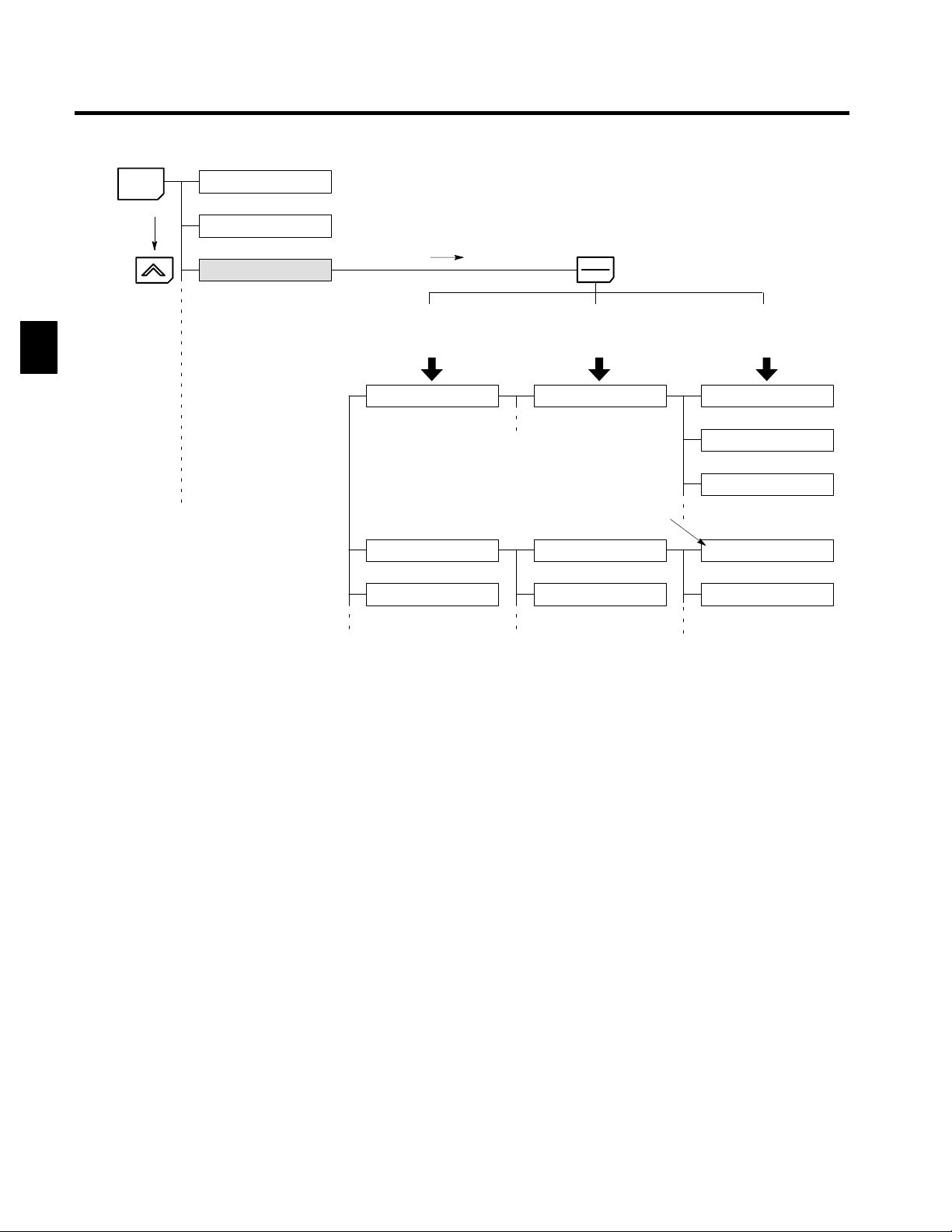
J User Constant Structure and Three Access Levels
The VS-616G5 has a number of user constants for setting various functions. These user constants are classified into a hierarchy to make them easier to use.
The levels are as follows from top to bottom: Modes, Groups, Functions, and Constants. The access levels
for the user constants are shown in Table 1.2.
Table 1 . 2 Access Levels for User Constants
Level Contents
Mode Classified according to operation
Operation: For operating the Inverter. (All kinds of monitoring are possible.)
Initialize: For selecting the language displayed at the Digital Operator, setting
Programming: For setting user constants for operation.
Autotuning: For automatic calculation or setting motor constants. (Only under
Modified constants: For referencing or changing user constants after shipping.
Groups Classified by application.
Functions Classified by function. (See user constants.)
Constants Individual user constant settings.
The VS-616G5 allows the following three access levels to be set in order to further simplify setting user
constants. (An access level is a range of user constants that can be referenced or set.)
Quick-Start Reads/sets user constants required for trial operation. [Factory setting]
Basic Reads/sets user constants that are commonly used.
Advanced Reads/sets all the user constants that can be used.
access levels, initialization, and the control modes.
the vector control mode.)
1.1 Outline and Functions
1
In general, press the DATA/ENTER Key to move from an upper to a lower level. This varies somewhat,
however, according to the access level, as shown in Fig. 1.1. For the Quick-Start access level, which has
few user constants that can be set, pressing the DATA/ENTER Key jumps directly to the user constant level;
whereas for the Advanced access level, which has many user constants, pressing the DATA/ENTER Key
first leads to the Group level.
1-5
Page 22
Introduction
1.1.2 Functions
1
MENU
Operation mode
Initialize mode
Programming mode
DATA
ENTER
(Advanced) (Basic) (Quick-Start)
Displays group level.
Application
Tuning
Reference
Displays function level.
b1 Sequence
Constant to be changed
C1 Accel/Decel
C2 S-curve Acc/Dec
Displays constant level.
b1-01 Reference source
b1-02 Run source
b1-03 Stopping method
C1-01 Accel Time 1
C1-02 Decel Time 1
(Mode)
(Groups)
Fig 1.1 Access Level Structure
(Functions)
(Constants)
1-6
Page 23
1.2 Nomenclature
This section provides the names of VS-616G5 components, and the components and functions of the Digital Operator.
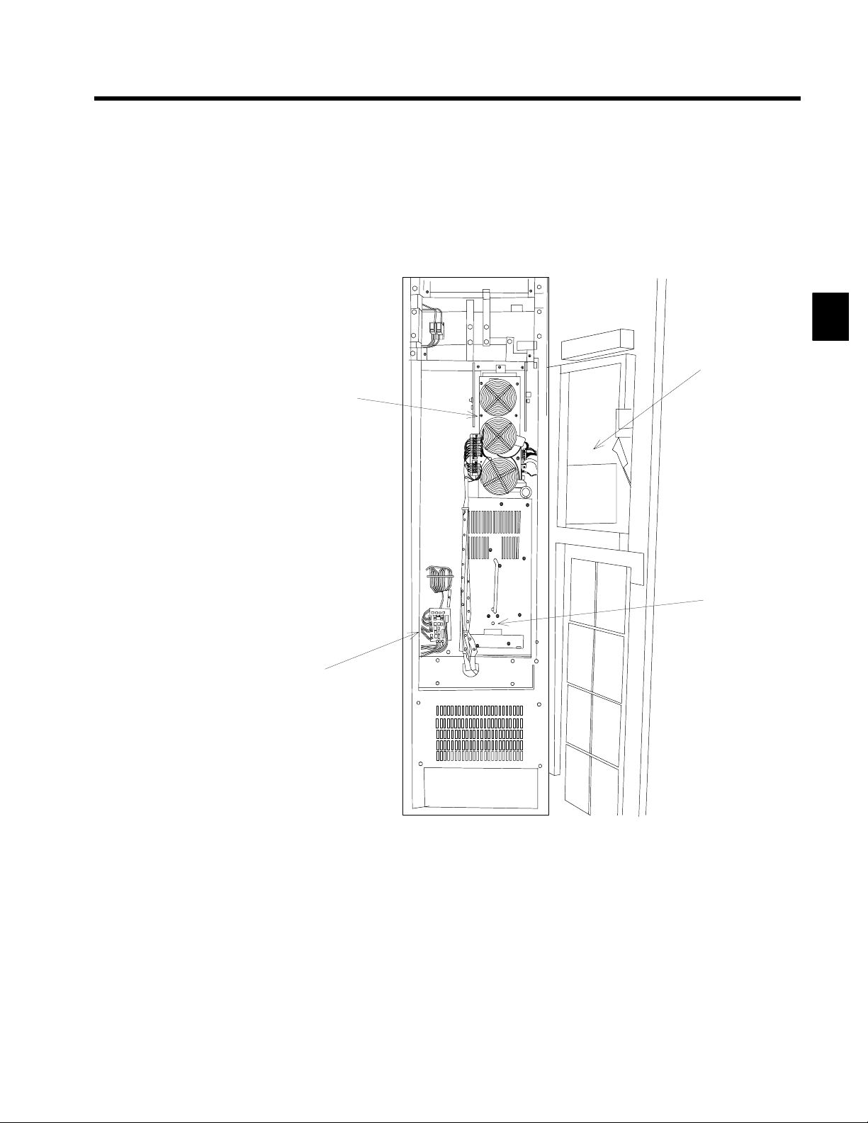
1.2.1 VS-616G5 Components
The appearance of Inverter and the names of its components are shown in Figure 1.2.
Inverter Module
1.2 Nomenclature
1
Control Unit
Power Supply
Unit
Fig 1.2 Appearance of VS-616G5, Model CIMR-G5A (400 V, 200 kW)
Charge lamp
1-7
Page 24
Introduction
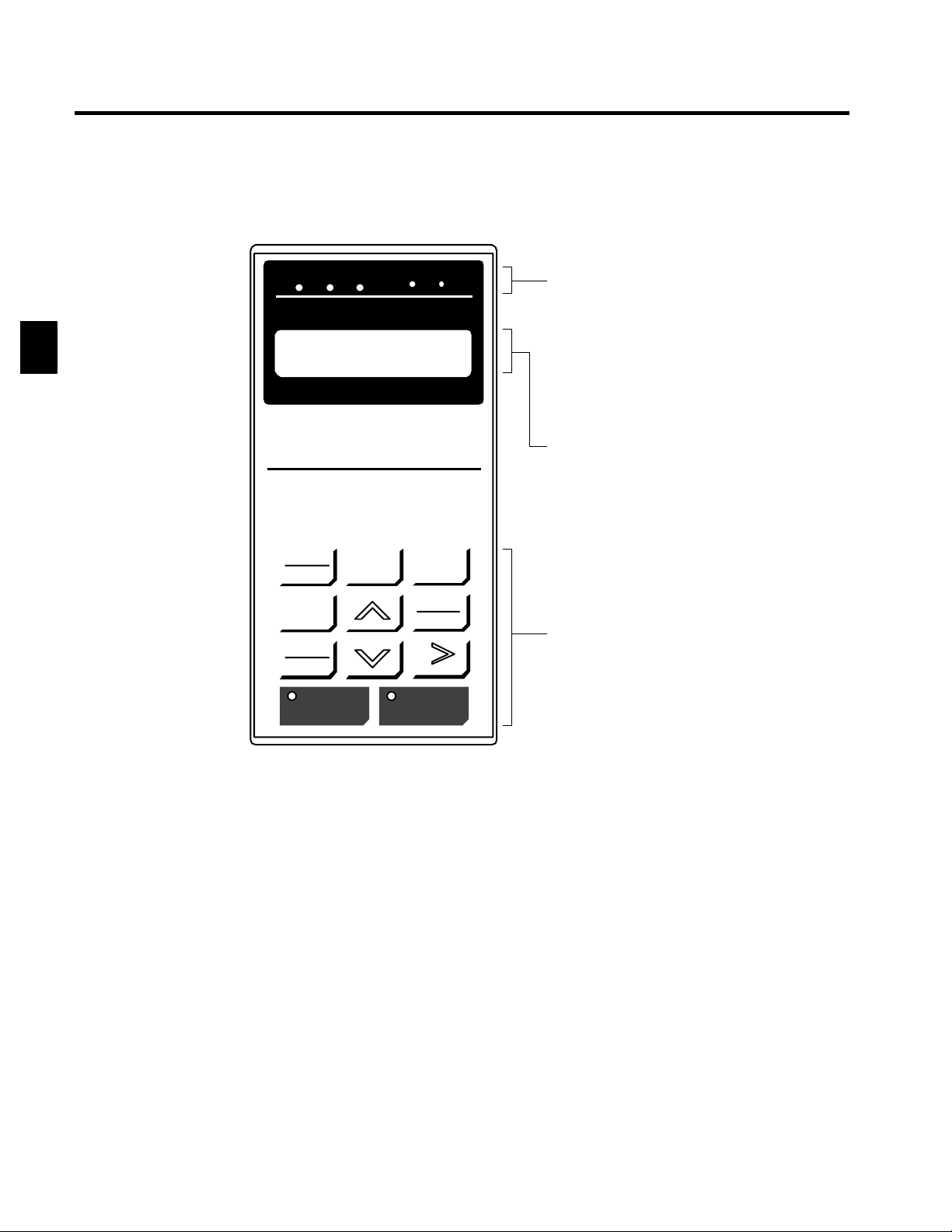
1.2.2 Digital Operator Components
1.2.2 Digital Operator Components
This section describes the component names and functions of the Digital Operator. The component names
and functions are shown in Figure 1.3 and key functions are described in Table 1.3.
1
DRIVE FWD REV REMOTE
Frequency Ref
U1--01 = 00.00 HZ
DIGITAL OPERATOR
JVOP-130
LOCAL
REMOTE
JOG
FWD
REV
RUN STOP
SEQ REF
MENU
ESC
DATA
ENTER
RESET
Operation Mode Indicators
DRIVE: Lit when in operation mode.
FWD: Lit when there is a forward reference input.
REV: Lit when there is a reverse reference input.
SEQ: Lit when an operation reference from the
REF: Lit when the frequency reference from con-
control circuit terminal is enabled.
trol circuit terminals 13 and 14 is enabled.
Data Dis play
Two-line LCD that displays data for monitoring,
user constants, and set values with 16 characters
per line.
Keys
Execute operations such as setting user constants,
monitoring, jogging, and autotuning.
Fig 1.3 Digital Operator Component Names and Functions
1-8
Page 25
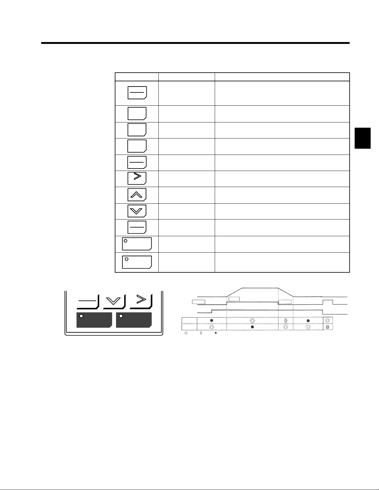
Table 1 . 3 Key Functions
Key Name Function
Switches between (LOCAL) operation via the Digital Operator
LOCAL
REMOTE
LOCAL/REMOTE Key
and control circuit terminal (REMOTE) operation.
This key can be enabled or disabled by setting a user constant
(o2-01).
1.2 Nomenclature
MENU
ESC
JOG
FWD
REV
RESET
DATA
ENTER
RUN
MENU Key Displays menus.
ESC Key Returns to the status before the DATA/ENTER Key was pressed.
JOG Key
FWD/REV Key
RESET Key
Increment Key
Decrement Key
DATA/ENTER Key
RUN Key
Enables jog operation when the VS-616G5 is being operated
from the Digital Operator.
Selects the rotation direction of the motor when the VS-616G5 is
being operated from the Digital Operator.
Sets the number of digits for user constant settings.
Also acts as the reset key when a fault has occurred.
Selects menu items, groups, functions, and user constant names,
and increments set values.
Selects menu items, groups, functions, and user constant names,
and decrements set values.
Enters menu items, functions, constants, and set values after they
are set.
Starts the VS-616G5 operation when the VS-616G5 is in operation with the Digital Operator.
Stops VS-616G5 operation.
STOP
STOP Key
This key can be enabled or disabled by setting a user constant
(o2-02) when operating from the control circuit terminal.
Note Except in diagrams, keys are referred to using the key names listed in the above table.
1
FWD
REV
RUN STOP
RESET
Inverter output frequency
STOP
Frequency setting
RUN
OP
ST
Lit Blinking Not lit
RUN
STOP
The RUN and STOP indicators light and blink to indicate operating status.
Fig 1.4 RUN and STOP Indicators
1-9
Page 26

1
Introduction
1.2.2 Digital Operator Components
1-10
Page 27

2
Handling Inverters
This chapter describes the checks required upon receiving a VS-616G5 Inverter and describes installation methods.
2.1 Confirmations upon Delivery 2 - 2..............
2.1.1 Nameplate Information 2 - 2.........................
2.2 Temporary Storage 2 - 3......................
2.2.1 Storage Location 2 - 3..............................
2.2.2 Storage Method 2 - 3...............................
2.3 Transportation 2 - 4..........................
2.3.1 Precautions During Transportation 2 - 4................
2.3.2 Lifting with Wires 2 - 4.............................
2.3.3 Transporting on Rollers 2 - 5.........................
2.4 External Dimensions and Mounting
Dimensions 2 - 6...........................
2.5 Checking and Controlling the Installation
Site 2 - 10.................................
2.5.1 Installation Site 2 - 10...............................
2.5.2 Controlling the Ambient Temperature 2 - 10..............
2.5.3 Protecting the Inverter Panel from Foreign Matter 2 - 10....
2.5.4 Floor Level 2 - 10..................................
2.5.5 Inverter Panel Connections
(Side-by-side Connection) 2 - 10....................
2.5.6 Tightening Anchor Bolts 2 - 11........................
2.6 Installation Orientation and Space 2 - 13..........
2
2.7 Removing/Attaching the Digital Operator 2 - 14....
2-1
Page 28
2
Handling Inverters
2.1.1 Nameplate Information
2.1 Confirmations upon Delivery
D Never install an Inverter Panel that is damaged or missing components.
Doingsocanresult in injury.
Check the following items as soon as the Inverter is delivered.
Table 2 . 1 Checks
Item Method
Has the correct model of Inverter been
delivered?
Is the Inverter damaged in any way? Inspect the entire exterior of the Inverter to see if there are any scratches or
Are any screws or other components
loose?
If you find any irregularities in the above items, contact the agency from which you purchased the Inverter or
your Yaskawa representative immediately.
2.1.1 Nameplate Information
CAUTION
Check the model number on the nameplate on the back of the front panel of
the Inverter Panel (See 2.1.1).
other damage resulting from shipping.
Use a screwdriver or other tools to check for tightness.
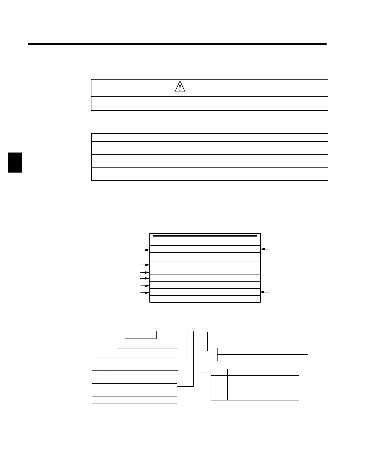
J Example Nameplate
Standard domestic (Japan) Inverter: 3-phase, 400 VAC, 200 kW standards
TRANSISTOR INVERTER
Model number
Input specifications
Output specifications
Output capacity
Lot number
Serial number
MODEL CIMR--G5A4200 SPEC 42008A
RATINGS
INPUT 380 -- 460 V 385 A
OUTPUT 3PH 0 -- 460 VAC 0 -- 414 A
CODE No. 71616--G5A42008A.
SER No. MASS 800Kg DATA
YASKAWA ELECTRIC CORPORATION
J Inverter Panel Model Numbers
CIMR -G5A 4 2008 A
Inverter Panel
VS-616G5
No. Specification
A Standard domestic model
No. Voltage Class
4 AC input, 3-phase, 400 V
5 AC input, 3-phase, 575 V
KVA
JAPAN
Revision code (Specification code is entered for special specifications.)
No. Protective structure
8 Enclosed self-standing structure
No. Max. Motor Capacity
200
400
to
800
200 kW
400 kW
to
800 kW
Inverter specifications
Mass
2-2
Page 29
2.2 Temporary Storage
Observe the following precautions when storing the Inverter Panel for a period of time before installation.
2.2.1 Storage Location
Store the Inverter Panel under the following conditions.
D Indoors
D In a level and flat location
D In a well-ventilated location at a low temperature and low humidity
D In a locations not subject to vibration
D In a locations not subject to dust, harmful gases, or salt
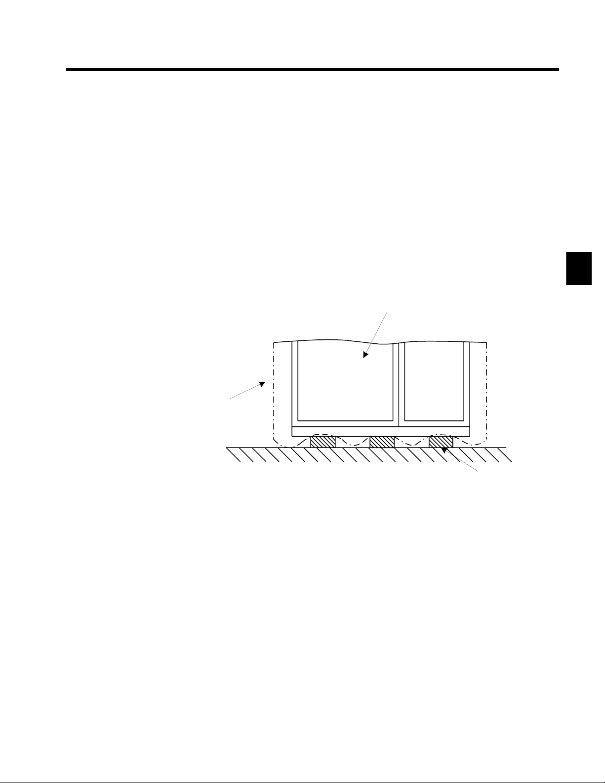
2.2.2 Storage Method
2.2 Temporary Storage
Store the Inverter Panel in the following manner.
D Place the Inverter Panel on sleepers as shown below. (Do not place it directly on the floor.)
D Cover the Inverter Panel with the polyethylene cover that is attached at the time of shipment.
Inverter Panel
Cover
Floor
Sleeper
Fig 2.1 Storage Method
2
2-3
Page 30
2
Handling Inverters
2.3.1 Precautions During Transportation
2.3 Transportation
D Crane operation must be performed only by an authorized person qualified to operate cranes.
Otherwise, injury or damage caused by dropping lifted objects.
The Inverter Panel should be transported using either the lifting wires or rollers. Before transporting the Inverter
Panel, make sure that the door and internal components are secured.
2.3.1 Precautions During Transportation
D Do not push or drag the Inverter Panel on concrete floors or floors other than ones which have embedded
channel base or steel plates.
D Do not turn over or roll the Inverter Panel.
D Do not subject the Inverter Panel to vibration or shock exceeding 4.9 m/s
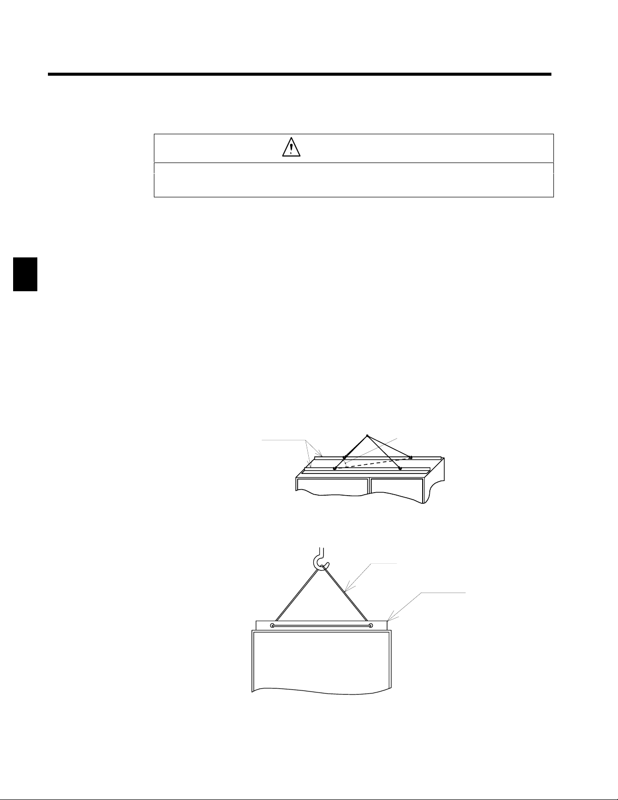
2.3.2 Lifting with Wires
D When lifting the Inverter Panel, use wires with sufficient strength that withstand the mass.
D When using wires to lift the Inverter Panel, route wires so as to provide a lifting angle of 60° min., as
shown in Figuure 2.2 below. If the lifting angle is less than this, allowable lifting loads will not be assured.
D Place each wire through the lifting hole provided in the lifting angle.
D Do not lift the Inverter Panel as shown in Figure 2.3.
D When lifting the Inverter Panel using a crane, first gradually lift the wires until they become taught. Lift
the Inverter Panel only after making sure that the wires are taught. Lift the Inverter Panel up or down
slowly. When placing the Inverter Panel on the floor, stop lowering it just before it reaches the floor and
then slowly lower it on the floor to avoid any shock to the Inverter Panel.
Lifting angle
CAUTION
60° min.
2
(0.5 G) during transportation.
Fig 2.2 Wire Lifting
Fig 2.3 Bad Lifting Example
2-4
Wire
Lifting angle
Page 31

2.3.3 Transporting on Rollers
When transporting the Inverter Panel using rollers, carefully push the Inverter Panel so as not to distort the frame
or damage the Inverter Panel surface.
D Use rollers equivalent to gas pipes with an approx. diameter of 30 to 50 mm. The length should be such
that the rollers extend beyond the Inverter Panel on both sides by approx. 100 mm.
D When the Inverter Panel has been moved to a desired location, carefully lift the Inverter Panel with a
lifting bar and remove the rollers. Insert the lifting bar at the four corners of the box as shown in Figure 2.4.
When inserting a lifting bar under the door, be careful not to damage the door with the lifting bar.
2.3 Transportation
2
Fig 2.4 Lifting Bar Insertion Locations
2-5
Page 32

Handling Inverters
2.4 External Dimensions and Mounting Dimensions
J 400-V Class (200 kW) and 575-V Class (300 kW) Inverter Panels
2
175
2100
50
600
1200
YASK AWA
VARISPEED
600
With door
open:
570 max.
770 5
30
Generated
loss (W)
CIMR--G5Aj
Converter Module 1030 1030
Inverter Module 3430 4410
Control Unit 50 50
Discharge Resistor 60 100
Control Power Transformer 80 80
DC Reactor 150 150
Coupling Reactor -- --
Tot a l 4800 5820
2-6
4200 5300
Page 33

2.4 External Dimensions and Mounting Dimensions
J 400-V Class (400 kW) and 575-V Class (600 kW) Inverter Panels
75
VARISPEEDYASK AWA
100
0
Generated
loss (W)
570
With door
600
1400
CIMR--G5Aj
Converter Module 2060 2060
Inverter Module 6860 8820
Control Unit 50 50
Discharge Resistor 120 200
Control Power Transformer 80 80
DC Reactor 370 370
Coupling Reactor 1480 1480
Tot a l 11020 13060
800
4400 5600
125
open:
770 max.
30
615
770
2
5
2-7
Page 34

Handling Inverters
J 400-V Class (600 kW) and 575-V Class (900 kW) Inverter Panels
2
175
2100
50
800
200 800
1000
1800
VARISPEEDYASK AWA
627
570
125
With door
open:
770 max.
770 5
30
Generated
loss (W)
CIMR--G5AV
Converter Module 3090 3090
Inverter Module 10290 13230
Control Unit 50 50
Discharge Resistor 180 300
Control Power Transformer 80 80
DC Reactor 700 700
Coupling Reactor 2220 2220
Tot a l 16610 19670
4600 5900
2-8
Page 35

2.4 External Dimensions and Mounting Dimensions
J 400-V Class (800 kW) and 575-V Class (1200 kW) Inverter Panels
175
2100
50
700 700
800 1400
2200
YASKAWA
VA-
RISPEED
570
125
With door
open:
770 max.
627
770 5
30
2
Generated
loss (W)
CIMR--G5Aj
4800 512C
Converter Module 4120 4120
Inverter Module 13720 17640
Control Unit 50 50
Discharge Resistor 240 400
Control Power Transformer 80 80
DC Reactor 740 740
Coupling Reactor 2960 2960
Tot a l 21910 25990
2-9
Page 36

2
Handling Inverters
2.5.1 Installation Site
2.5 Checking and Controlling the Installation Site
Install the VS-616G5 in the installation site described below and maintain optimum conditions.
2.5.1 Installation Site
Install the Inverter Panel under the following conditions.
D Install the Inverter Panel at an altitude of 1,000 m or less.
D Install the Inverter Panel in a location with an ambient temperature ranging from --5 to 40 °C.
• Do not expose the Inverter Panel to hot air currents.
• Install the Inverter Panel in a well-ventilated location. If the Inverter Panel is located in a poorly
ventilated location, ambient temperature will rise due to the Inverter panel or other heat sources.
D Install the Inverter Panel in a location free from harmful gasses or sea wind that may cause rust or corro-
sion.
D Install the Inverter Panel in a location free from dripping water or condensation.
Observe the following precautions when installing the Inverter Panel indoors.
• Thebuilding roof made of metal or glass may cause water condensation to drip on the Inverter Panel.
• Water leakage from water pipes may drip on the Inverter Panel.
• When installing the Inverter Panel in a concrete room, particularly in building underground, where
concrete tends to keep moisture, the Inverter Panel may be affected by moisture. In such case, provide a space heater inside the Inverter Panel to constantly keep the in-panel temperature higher than
the ambient temperature.
D Install the Inverter Panel in a clean location free from dust. Otherwise, contacts may malfunction or in-
sulation destruction may occur.
D Install the Inverter Panel in a location free from excessive vibration or shock.
D Install the Inverter Panel in a location free from explosive or combustible gases.
D Installthe Inverter Panel in a location where openings are provided for cleaning,inspection, and mainte-
nance. (The Fire Protection Law specifies minimum openings in the front and back sides of the Inverter
Panel.)
2.5.2 Controlling the Ambient Temperature
To enhance the reliability of operation, the Inverter Panel should be installed in an environment free from
extreme temperature increases. If the Inverter Panel is installed in an enclosed environment, such as a box,
use a cooling fan or air conditioner to maintain the internal air temperature below 40°C.
2.5.3 Protecting the Inverter Panel from Foreign Matter
Place a cover over the Inverter Panel during installation to shield it from metal power produced by drilling.
Always remove the cover from the Inverter Panel after completing installation. Otherwise, ventilation will
be reduced, causing the Inverter Panel to overheat.
2.5.4 Floor Level
The floor where the Inverter Panel is installed must be level to within ±3 mm per square meter.
2.5.5 Inverter Panel Connections (Side-by-side Connection)
When connecting more than one Inverter Panel in a series, use connection bolts.
Tighten the four bolts along both the front side and back side. Tighten them carefully so that the front surfaces of each Inverter Panels are aligned with each other and so that all the connected Inverter Panels remain
stable.
2-10
Page 37

2.5 Checking and Controlling the Installation Site
Connection holes for Inverter Panels
(Six 14-dia holes)
Connection holes for other panels
(Eight 14-dia holes)
2
Fig 2.5 Inverter Panel Side-by-side Connection
The method for connecting Inverter Panels Side-by-side is different from the method for connecting an Inverter Panel with other panels.
M10×90 bolt
Hardwood washer
Mounting frame
Side plate
Fig 2.6 Side-by-side Connection Joint
2.5.6 Tightening Anchor Bolts
When the installation work described in 2.5.5, above, has been completed, secure the Inverter Panel with
four anchor bolts. Perform the foundation work according to the external dimensions drawings provided
by Yaskawa.
M10×60 bolt
Hardwood washer
M10 nut, S washer,
hardwood washer
Mounting frame
Side plate
Inverter Panel Inverter PanelInverter Panel Other panel
(b) Connection with an ordinary panel(a) Connection with Inverter Panel
M10 nut, S washer, hardwood washer
2-11
Page 38

Handling Inverters
2.5.6 Tightening Anchor Bolts
Main circuit lead-in port (for 400-V class (200 kW)
W4
W3
30
H3
H
H1
Control circuit lead-in port
and 575-V class (300 kW) Inverters only)
Anchor bolt hole
(Four 17-dia. holes)
80225
125
2
Main circuit lead-in port
Fig 2.7 Tightening Anchor Bolts
Maximum mo-
tor capacity
400 V, 200 kW
575 V, 300 kW
400 V, 400 kW
575 V, 600 kW
400 V, 600 kW
575 V, 900 kW
400 V, 800 kW
575 V, 1200 kW
H2
30
W W1 W2 W3 W4 H H1 H2 H3
1200 960 300 125 145
1400 1160 500 125 125
1800 1560 700 125 165
2400 1960 1100 115 160 95 580
125
60
W
125
770 710
50
90
W2
120120 W1
240 435
240
Anchor bolt
Fig 2.8 Details of Anchor Bolts
2-12
710
Page 39

2.6 Installation Orientation and Space
Install the Inverter Panel so as not to reduce cooling effects. When installing the Inverter Panel, always provide
the following installation space to allow normal heat dissipation.
J 400-V Class (200 kW, 400 kW, 600 kW, and 800 kW) and 575-V Class (300 kW, 600
kW, 900 kW, and 1200 kW) Inverters
The following example shows examples for the 400-V class (400 kW) and 575-V class (600 kW) Inverters.
Air
VARISPEEDYASK AWA
100 mm min.
2.6 Installation Orientation and Space
10 mm min.
2
Air
Fig 2.9 Installation Orientation and Space for VS-616G5 Inverters
2-13
Page 40

2
Handling Inverters
2.7 Removing/Attaching the Digital Operator
Remove or attach the Digital Operator using the following procedure.
J Removing the Digital Operator
Press the lever on the side of the Digital Operator in the direction of arrow 1 to unlock the Digital Operator,
and lift the Digital Operator in the direction of arrow 2 to remove the Digital Operator as shown in the following illustration.
Digital Operator
Control Unit Panel
1
2
Fig 2.10 Removing the Digital Operator
J Mounting the Digital Operator
IMPORTANT
1. Hook the Digital Operator at A (two locations) in the direction of arrow 1 as shown in the following
illustration.
2. Press the Digital Operator in the direction of arrow 2 until it snaps in place at B (two locations).
Hook A
Digital Operator
1
Hook B
Control Unit Panel
2
Fig 2.11 Mounting the Digital Operator
Do not remove or attach the Digital Operator using methods other than those described above, otherwise the
Inverter Panel may break or malfunction due to imperfect contact.
2-14
Page 41

3
Wiring
This chapter describes wiring terminals, main circuit terminal connections,
main circuit terminal wiring specifications, control circuit terminals, and
control circuit wiring specifications.
3.1 Connection Diagram 3 - 3.....................
3.2 Terminal Positions 3 - 5.......................
3.3 Cable Sizes 3 - 7............................
3.4 Wiring Main Circuit Terminals 3 - 9.............
3.4.1 Main Circuit Terminal Functions 3 - 9.................
3.4.2 Main Circuit Configurations 3 - 10.....................
3.4.3 Precautions for Wiring Main Circuit Power Input 3 - 10.....
3.5 Wiring Control Circuit Terminals 3 - 12...........
3.5.1 Control Circuit Terminal Functions 3 - 12................
3.6 Wiring Check 3 - 13...........................
3
3.7 Installing and Wiring PG Speed Control
Cards 3 - 14................................
3.7.1 Installing a PG Speed Control Card 3 - 14...............
3.7.2 PG Speed Control Card Terminal Blocks 3 - 15...........
3.7.3 Wiring a PG Speed Control Card 3 - 17.................
3.7.4 Wiring PG Speed Control Card Terminal Blocks 3 - 22.....
3.7.5 Selecting the Number of PG (Encoder) Pulses 3 - 25.......
3.8 Grounding 3 - 27.............................
3.8.1 Connection of Ground Bus Bar 3 - 27...................
3.8.2 Connection of Ground Cable for Control Signals 3 - 27.....
3-1
Page 42

Wiring
WARNING
D Always turn OFF the input power supply before wiring terminals.
Otherwise, an electric shock or fire can occur.
D Wiring must be performed by an authorized person qualified in electrical work.
Otherwise, an electric shock or fire can occur.
D Be sure to ground the ground terminal.
(400 V Class and 575 V Class Inverters: Ground to 10 Ω or less)
Otherwise, an electric shock or fire can occur.
D Always check the operation of any emergency stop circuits after they are wired.
Otherwise, there is the possibility of injury. (Wiring is the responsibility of the user.)
D Never touch the output terminals directly with your hands or allow the output lines to come into
contact with the Inverter Panel case. Never short the output circuits.
Otherwise, electrical shock or grounding can occur.
CAUTION
3
D Check to be sure that the voltage of the main AC power supply s atisfies the rated voltage of the
Inverter Panel.
Injury or fire can occur if the voltage is not correct.
D Do not perform voltage withstand tests on the Inverter Panel.
Voltage withstand test can damage semiconductor elements and other components.
D Connect Braking Resistor Units and Braking Units as shown in the I/O wiring examples.
Otherwise, a fire can occur.
D Tighten all terminal screws to the specified tightening torque.
Otherwise, a fire may occur.
D Do not connect AC power to output terminals U, V, and W.
The interior parts of the Inverter Module will be damaged if voltage is applied to the output terminals.
D Do not connect phase -advancing capacitors or LC/RC noise filters to the output circuits.
The internal Inverter Panel will be damaged if voltage is applied to the output terminals.
D Do not connect electromagnetic switches or contactors to the output circuits.
If a load is connected while the Inverter Panel is operating, surge current will cause the overcurrent protection circuit to operate.
3-2
Page 43

3.1 Connection Diagram
The connection diagram of the VS-616G5 is shown in Figure 3.1.
When using the Digital Operator, the motor can be operated by wiring only the main circuits.
3.1 Connection Diagram
3
3-3
Page 44

Wiring
Braking Resistor Unit (Optional)
Braking Unit
(Optional)
3
Forward Run/Stop
Reverse Run/Stop
Multi-function contact
input 1
Multi-function contact
input 2
Multi-function contact
input 3
Multi-function contact
input 4
Multi-function contact
input 5
Multi-function contact
input 6
Speed setting
resistor (2 kΩ)
Frequency reference
Frequency reference
Multi-function
analog input
*Power transformer for
12-phase rectification
MCCB
Control power input
terminals
200-VAC input terminals for
ventilation fan
Speed setting adjust ment resistor (2 kΩ)
R/L1
S/L2
When using the 12-phase
rectification input, remove the input
T/L3
terminal short-circuit bus bar.
R1/L11
S1/L21
T1/L31
r/
(Not for 575 V)
575 V:
r200
1TB
9
10
11
12
13
14
15
16
17
38
44
34
36
39
42
35
VS--616G5
1
2
200/
200
2
400
400/
575/ 575
2
200
Forward run command
(forward when closed)
Reverse run command
(reverse when closed)
(External fault)
(Fault reset)
(Master/auxiliary speed)
(Multi-step speed 2)
(Jog reference)
(External baseblock
reference)
Sequence common
(Insulated from 0V
terminal)
Shield terminal
--15 V power for analog refer-
ence
+15 V power for analog
reference
Master speed frequency reference
(--10 to +10V/0 to 10V)
Master speed frequency
reference (4 to 20 mA)
Multi-function analog input
(--10to+10V/0to10V)
Speed reference
common
0V
+
1
4CN
2CN
3CN
Frequency meter
Output ammeter
0V
--
PG
(Optional)
Reference
(Optional)
Monitor
(Optional)
FM
AM
U/T1
V/T2
W/T3
2TB
2TB
1TB
+
+
F1
Ventilation fan fault detection
F2
45
48
Analog output
monitor
46
25
Fault contact output
52
250 VAC, 1A max.
30 VDC, 1Amax.
23
53
Operation output
250 VAC, 1A max.
57
30 VDC, 1Amax.
19
Open collector 1
20
Open collector 2
50
Multi-function output common
Motor
IM
PG
Multi-function
open-collector output
48 VDC, 50 mA max.
Note (1) Double circles indicate main circuit terminals and single circles indicate control circuit terminals.
(2) When using the 12-phase rectification, the user must prepare the transformer.
Fig 3.1 Connection Diagram (Model CIMR-G5A4200 Shown Above)
3-4
Page 45

3.2 Terminal Positions
J 400-V Class (200 kW) and 575-V Class (300 kW) Inverters
+1 --
3.2 Terminal Positions
--
Converter Module
Input terminals
(Connector)
R1/L11R/L1S1/L21S/L2T/L3T1/L31
Work cable input
side (Main circuit)
Connection cable: 325 mm2max.)
(600-V CV cable, etc.)
Note The main circuit terminals on the output side are provided as bus bar terminals on the side
surface. Connections are normally made to the output terminal block on the right side.
2
Work cable
(Control circuit)
1
U/T1V/T2W/T3
Work cable output
side (Control circuit)
Connection cable: 325 mm
(600 V CV cable, etc.)
DC bus
Inverter
Module
Output
terminals
1 1TB (Control circuit terminal block)
2 2TB (General terminal block)
2
max.)
3
3-5
Page 46

Wiring
J 400-V Class (400 kW, 600 kW, 800 kW) and 575-V Class (600 kW, 900 kW,
1200 kW) Inverters
The following illustration is for 400-V class (400 kW) and 575-V class (600 kW) Inverters.
+1 --
--
3
Converter Module
Input terminals
(Connector)
S/L2S1/L21T1/L31 R1/L11T/L3 R/L1
Work cable input
side (Main circuit)
Connection cable: 325 mm2max.
(600-V CV cable, etc.)
Note The main circuit terminals on the output side are provided as bus bar terminals on the side
surface. Connections are normally made to the output terminal block on the right side.
2
1
Work cable
(Control circuit)
DC bus
Inverter Module
U/T1
V/T2
W/T3
Output
terminals
1 1TB (Control circuit terminal block)
2 2TB (General terminal block)
3-6
Page 47

3.3 Cable Sizes
J Connection Cables
1TB (Control Circuit Terminal Block)
CN1
20P
CN2
50P
Top Bottom
1
30
2
31
32
3
33
4
PS5D-INV-LA
Connection Cable Specifications
Applicable cable: 2 mm
Charge current: 0.5 mA
End treatment: 7 mm
2
max.
3.3 Cable Sizes
3
10P
2TB (General
Terminal Block)
CN3
56
27
28
57
29
58
(M2.3)
UK--15 (M3.5)
Connection cable: 2 mm
UKT--81(M5)
Connection cable: 14 mm
2
2
max.
Fig 3.2 Connection Cables
7mm
max.
3-7
Page 48

3
Wiring
J Transmission Cables
When the Inverter Panels is designed to be applicable to transmission connection, the Inverter Panel is provided with transmission junction terminals.
Connect the transmission cables directly to the transmission junction terminals on the input side and output
side.
Treat the transmission cables as low-current cables and separate them from high-power lines.
Terminal Block Arrangement
JC--215--01
4X3XSX2X1
XX
Transmission Cable
IPEV--S, 1Px1.25 mm
E
M3.5--8L
2
Fig 3.3 Transmission Cable
3-8
Page 49

3.4 Wiring Main Circuit Terminals
MainC
i
itPowerI
(
A
(Atthetimeofshipmen
t,short-circuitbusbarsareconnectedbetweenR/L1andR1/L1
1
//,//
w
)
InverterOutputs
k
i
Control
PowerI
(
ForModulef
)
ControlPowerInput
s
i
lationf
3.4.1 Main Circuit Terminal Functions
Main circuit terminal functions are summarized according to terminal symbols in Table 3.1 . Wire the terminals correctly for the desired purposes.
3.4 Wiring Main Circuit Terminals
Voltage Class 400-V Class 575-V Class
Table 3 . 1 Main Circuit Terminal Functions
CIMR-G5Aj
R/L1
S/L2
T/L3
R1/L11
S1/L21
T1/L31
U/T1
V/T2
W/T3
¨1
©
200/ℓ2200
400/ℓ2400
r/ℓ
1
575/ℓ2575 --
r200
200
t the time ofshipment, short-circuit bus bars are connected between R/L1 and R1/L11,
S/L2 and S1/L21, and between T/L3 and T1/L31. Remove these short-circuit bus bars
4200 to 4800 5300 to 512C
rcu
hen applying 12-phase rectification.
Inverter Outputs
For connecting theBra
nputs
an powerinput
Powerinput to the Inverter Panelvent
Ground
nputs
ng Unit
--
--
Control Power Inputs
(For Module fan power input)
an
,
3
3-9
Page 50

Wiring
3.4.3 Precautions for Wiring Main Circuit Power Input
3.4.2 Main Circuit Configurations
The main circuit configuration of the CIMR-G5A4800 is shown below.
3
R/L1
S/L2
T/L3
R1/L11
S1/L21
T1/L31
r/
2
200/
200
2
400/ 400
1CONV
200 VAC
2CONV
200 VAC
1
To fan and MC
200 VAC
Power supply
to control circuit/Gate drive
To Gate Drive
MC
1INV
Gate Drive
2INV
3INV
4INV
Operator
Control
circuit
I/O
200 VAC
Power supply
200 VAC
Power supply
200 VAC
Power supply
200 VAC
Power supply
U/T1
V/T2
W/T3
r200
200
F1
F2
M
Fig 3.4 Main Circuit Configuration (CIMR-G5A4800)
3.4.3 Precautions for Wiring Main Circuit Power Input
At the time of shipment, short-circuit bus bars are provided between R/L1 and R1/L11, S/L2 and S1/L21,
and between T/L3 and T1/L31 on the main circuit power input terminal. Remove these short-circuit bus bars
when applying 12-phase rectification.
R/L1
S/L2
T/L3
R1/L11
S1/L21
T1/L31
Fig 3.5 Short-circuit Bus Bar Connections
U/T1
V/T2
W/T3
Atthetimeofshipment, short-circuit
bus bars are connected between
these terminals.
3-10
Page 51

3.4 Wiring Main Circuit Terminals
R/L1
S/L2
T/L3
R1/L11
S1/L21
T1/L31
Remove the short-circuit bus bars when
applying 12-phase
rectification.
Fig 3.6 Wiring when Applying 12-phase Rectification
U/T1
V/T2
W/T3
3
3-11
Page 52

,
Photocouplerisolation
p
(
d
b
ttingH
1-0
1
outpu
t
p
input
f
A
VAC
t)T
2
3and25
b
dwh
l
i
1Amax.at250VA
C
gg(
p
g
q
50mAmax.at48V
A
g
Analo
g
2mAmax.
g
p
Shieldstrip
3
Wiring
3.5.1 Control Circuit Terminal Functions
3.5 Wiring Control Circuit Terminals
3.5.1 Control Circuit Terminal Functions
The functions of the control circuit terminals are shown in Table 3.2. Use the appropriate terminals for the
correct purposes.
Table 3 . 2 Control Circuit Terminals
External
Terminal
Code
1TB
Control PCB
Terminal
Code
9CN
9
10 18 Reverse run/stop command Reverse run when CLOSED; stopped when OPEN.
11 19 External fault input Fault when CLOSED; normal
12 20 Fault reset Reset when CLOSED
13 21
14 22
15 23 Jog frequency reference Jog run when CLOSED.
16 24 External baseblock Inverter output stopped when
17 25 Sequence input common --
34 1 15 V power output 15 V power supply for analog references 15 V
44 10 --15 V power output --15 V power supply for analog references --15 V
36 4
39 6
42 8 Multi-function analog input --10 to 10 V/--100% to 100%
35 3 Analog input common --
TB2
52
25 3
23 1
53 4 Running signal (1NO con57 5 Sequence
10CN
19
20 12 Speed agree detection Within ±2 Hz of set frequency when
50 18 Open-collector output com-
45 2
48 4
46 3
29 -- -- For shield connection
38 -- -41 -- -47 -- -51 -- -58 -- --
Typ e Signal Name Function Signal Level
17 Forward run/stop command Forward run when CLOSED; stopped when OPEN.
Multi-function contact inputs
Command signals can be
selecte
to H1-06.)
--
1 (H4-01, H4-02)
2 (H4-04,H4-05)
-- --
yse
Auxiliary analog input
(H3-05)
en outputsigna
outputs
10
2
Sequence
output
signals
Analog
ut
in
signals
output
signals
nalo
output
signals
Shield stri
connection
when OPEN.
Main/auxiliary switch Auxiliary frequency reference
Multi-step speed reference2Multi-step setting 2 when
Master speed frequency
reference
Fault output signal
(Single-pole, double-throw
contac
tact)
Zero speed detection Zero level (b2-01) or below when
mon
Frequency output 0 to 10 V/100% frequency Multi-function analog monitor
Current monitor 5 V/Inverter rated current Multi-function analog monitor
Analog output common --
when CLOSED.
CLOSED.
CLOSED.
--10 to 10 V/--100% to 100%
0 to 10 V/0 to 100%
4 to 20 mA/0 to 100%
--10 to +10V/--100% to +100% 0 to 10V/0 to 100%
0 to 10 V/0 to 100%
Terminals 23 and 52 become open when output signal is
aulty.
erminals
faulty.
Operating when CLOSED. Multi-function
CLOSED
CLOSED.
ecome close
24 VDC, 8 mA
Photocoupler isolation
-
(Max. current: 20 mA)
(Max. current: 20 mA)
--10to+10V(20kΩ)
0to10V(20kΩ)
4to20mA (250Ω)
--10to+10V(20kΩ)
0to10V(20kΩ)
Dry contacts
Contact capacity:
max. at 250
1
s
1 A max. at 30 VDC
Open-collector output
50 mA max. at 48 V*
0to±10 V max. ±5%
2mAmax.
3-12
Page 53

3.6 Wiring Check
detection
Panelventilationfan
turnedONortheF1andF2terminalsbecomeclosedwhen
Contactcapacity
:
F1
2TB
* When driving an L load, such as a relay coil, always insert a flywheel diode as shown in Figure 3.7.
F2
-- --
-- --
Fan
detection
External power:
48 V max.
For detecting faulty Inverter
Panel ventilation fan
Coil
Detects faulty fan when the power supply to the fan is
turned ON or the F1 and F2 terminals become closed when
the power supply to the fan is turned OFF.
Flywheel diode
50 mA max.
Fig 3.7 Flywheel Diode Connection
3.6 Wiring Check
Check all wiring after wiring has been completed. Do not perform a buzzer check on control circuits.
D Is all wiring correct?
D Have any wire clippings, screws, or other foreign material been left?
D Are all screws tight?
D Are any wire ends contacting other terminals?
Dry contacts
Contact capacity:
1 A max. at 250 VAC
1 A max. at 30 VDC
The rating of the flywheel diode
must be at least as high as the circuit voltage.
3
3-13
Page 54

3
Wiring
3.7.1 Installing a PG Speed Control Card
3.7 Installing and Wiring PG Speed Control Cards
PG Speed Control Cards are used for executing speed control using a pulse generator (PG). There are four types
of PG speed control, as shown below. Select the type that fits the application and control method.
PG-A2 A-phase (single) pulse input for open collector output or complementary outputs, for V/f control
PG-B2 A/B-phase pulse input for open collector output or complementary outputs, for vector control
PG-D2 A-phase (single) pulse input for line driver input, for V/f control
PG-X2 A/B/Z-phase pulse input for line driver input, for vector control
3.7.1 Installing a PG Speed Control Card
Use the following procedure to install a PG Speed Control Card.
1. Turn OFF the main-circuit power supply of the Inverter Panel.
2. Leave it OFF for at least five minutes before opening the front door of the Inverter Panel. Check to be
sure that the CHARGE lamp is OFF.
3. After aligning to the Option-A connector on the control PCB located on the back of the front panel of
the Inverter Panel, pass the spacer through the spacer hole at the Card. (Refer to A in the illustration.)
Check to be sure that it is precisely aligned with the 4CN position, and snap it into the proper position.
Be sure to press it in firmly until you hear it snap into place.
Top
4CN
Option-A
Connector
3CN
Option-D
Connector
Option D
Ground terminal
Option A Option CD
PG Speed
Control
Card
Spacer
[Front]
Fig 3.8 Installing a PG Speed Control Card
Bottom
Control
board
2CN
Option-C
Connector
Option C
PG Speed
Control
Card
Spacer
[Side]
3-14
Page 55

3.7.2 PG Speed Control Card Terminal Blocks
+12V/opencollectorswitchingter-
Pulseinputtermina
l
l
TA1
A-ph
l
TA2
l
ppypg
)
TA1
Linedriverinput(RS-422levelinput)
)
The terminal specifications for each PG Speed Control Card are given in the following tables.
J PG-A2 (For V/f with PG Feedback Mode Only)
Table 3 . 3 PG-A2 Terminal Specifications
Terminal No. Contents Specifications
1
Power supplyfor pulse generator
2
3
+12 V/open collector switchingterminal
4
TA1
TA2 (E) Shield connection terminal --
J PG-B2 (For Flux Vector Control Mode Only)
5
Pulse input terminal
6
7
Pulse motor output termina
8
3.7 Installing and Wiring PG Speed Control Cards
12 VDC (±5%), 200 mA max.
0 VDC (GND for power supply)
Terminal for switching between12 V voltage input
and open collector input. For open collector input,
short across 3 and 4.
H: +4 to 12 V; L: +1 V max. (Maximum response
frequency: 30 kHz)
Pulse input common
12 VDC (+10%), 20 mA max.
Pulse monitor output common
3
Table 3 . 4 PG-B2 Terminal Specifications
Terminal No. Contents Specifications
1
Power supplyfor pulse generator
2
3
A-phase pulse input terminal
4 Pulse input common
5
B-phase pulse input terminal
6 Pulse input common
1
2
3
4
TA3 (E) Shield connection terminal --
ase monitor output termina
B-phase monitor output termina
12 VDC (±5%), 200 mA max.
0 VDC (GND for power supply)
H: +8 to 12 V
L: +1 V max.
(Maximum response frequency: 30 kHz)
H: +8 to 12 V
L: +1 V max.
(Maximum response frequency: 30 kHz)
Open collector output, 24 VDC, 30 mA max.
A-phase monitor output common
Open collector output, 24 VDC, 30 mA max.
B-phase monitor output common
J PG-D2 (For V/f with PG Feedback Mode Only)
Table 3 . 5 PG-D2 Terminal Specifications
Terminal No. Contents Specifications
1 12 VDC (±5%), 200 mA max. (see note)
2
Power supply for pulse generator
3
4 Pulse input + terminal
5 Pulse input -- terminal
6 Common terminal --
7 Pulse monitor output + terminal
8 Pulse monitor output -- terminal
TA2 (E) Shield connection terminal --
0 VDC (GND for power supply)
5 VDC (±5%), 200 mA max. (see note)
Line driver input(RS-422 level input
Maximum response frequency: 300 kHz
Linedriver output(RS-422leveloutput
3-15
Page 56

ppypg
TA1
)
Linedriverinput(RS-422levelinput)
)
3
Wiring
3.7.2 PG Speed Control Card Terminal Blocks
Note 5 VDC and 12 VDC cannot be used at the same time.
J PG-X2 (For Flux Vector Control Mode Only)
Table 3 . 6 PG-X2 Terminal Specifications
Terminal No. Contents Specifications
TA2
TA3 (E) Shield connection terminal --
Note 5 VDC and 12 VDC cannot be used at the same time.
1 12 VDC (±5%), 200 mA max. (see note)
2
Power supply for pulse generator
3
4 A-phase + input terminal
5 A-phase -- input terminal
6 B-phase + input terminal
7 B-phase -- input terminal
8 Z-phase + input terminal
9 Z-phase -- input terminal
10 Common terminal 0 VDC (GND for power supply)
1 A-phase + output terminal
2 A-phase -- output terminal
3 B-phase + output terminal
4 B-phase -- output terminal
5 Z-phase + output terminal
6 Z-phase -- output terminal
7 Control circuit common Control circuit GND
0 VDC (GND for power supply)
5 VDC (±5%), 200 mA max. (see note)
Line driver input(RS-422 level input
Maximum response frequency: 300 kHz
Linedriver output(RS-422leveloutput
3-16
Page 57

3.7.3 Wiring a PG Speed Control Card
Three-phase, 400 VAC
(575 VAC)
3.7 Installing and Wiring PG Speed Control Cards
Wiring examples are provided in the following illustrations for the PG Speed Control Cards.
J PG-A2 (For V/f with PG Feedback Mode Only)
12 V Voltage Input
VS-616G5
R/L1
U/T1
V/T2
S/L2
T/L3
W/T3
4CN
E
IM
PG-A2
4CN
TA1
E
TA2 ( E)
+12 V power supply
1
0 V power supply
2
3
4
12 V voltage output (A/B phase)
5
Pulse 0 V
6
7
Pulse monitor output
8
PG
3
Three-phase, 400 VAC
(575 VAC)
Fig 3.9 Wiring a 12 V Voltage Input
Open Collector Input
VS-616G5
R/L1
S/L2
T/L3
U/T1
V/T2
W/T3
4CN
E
D Shielded twisted-pair wires must be used for signal lines.
D Do not use the pulse generator’s power supply for anything other than the
pulse generator (encoder). Using it for another purpose can cause malfunctions
due to noise.
D The length of the pulse generator’s wiring must not be more than 100 meters.
Fig 3.10 Wiring an Open-collector Input
IM
PG-A2
4CN
TA1
E
TA2 ( E)
+12 V power supply
1
0 V power supply
2
3
4
Open collector output (A/B phase)
5
Pulse0V
6
7
Pulse monitor output
8
PG
3-17
Page 58

Wiring
3.7.3 Wiring a PG Speed Control Card
3
PG power
supply +12 V
Short for
open-collector input
Pulse
input
TA1
I/O Circuit Configuration
1
2
1k
3
4
5
6
2k
3k
Fig 3.11 I/O Circuit Configuration of the PG-A2
+12 V
0V
2k
+12 V
+12 V
0V
3.9 k
0V
0V
Pulse input
+12 V
1k
7
Pulse
monitor
output
8
TA1
3-18
Page 59

3.7 Installing and Wiring PG Speed Control Cards
J PG-B2 (For Flux Vector Control Mode Only)
Three-phase, 400 VAC
(575 VAC)
VS-616G5
R/L1
U/T1
S/L2
T/L3
V/T2
W/T3
4CN
E
IM
PG-B2
TA1
4CN
TA2
E
TA3 ( E)
Power supply +12 V
1
Power supply 0 V
2
A-phase pulse output (+)
3
A-phase pulse output (--)
4
B-phase pulse output (+)
5
B-phase pulse output (--)
6
1
A-phase pulse monitor output
2
3
B-phase pulse monitor output
4
D Shielded twisted-pair wires must be used for signal lines.
D Do not use the pulse generator’s power supply for anything other than the
pulse generator (encoder). Using it for another purpose can cause malfunctions
due to noise.
D The length of the pulse generator’s wiring must not be more than 100 meters.
D The direction of rotation of the PC can be set in user constant F1-05. The
factory preset if for forward rotation, A-phase advancement.
PG
3
PG power
supply +12 V
A-phase
pulse input
B-phase
pulse input
Fig 3.12 PG-B2 Wiring
I/O Circuit Configuration
TA1
1
+12 V
2
0V
150
3
4
150 180
150
5
6
150
180
470
180
470
180
D When connecting to a voltage-output-type PG (encoder), select a PG
that has an output impedance with a current of at least 12 mA to the
input circuit photocoupler (diode).
Fig 3.13 I/O Circuit Configuration of the PG-B2
Division rate circuit
A-phase
pulses
B-phase
pulses
TA2
1
A-phase pulse monitor
2
output
3
B-phase pulse monitor
output
4
A-phase
pulses
B-phase
pulses
3-19
Page 60

Wiring
3.7.3 Wiring a PG Speed Control Card
J PG-D2 (For V/f with PG Feedback Mode Only)
3
Three-phase, 400 VAC
(575 VAC)
VS-616G5
R/L1
U/T1
V/T2
S/L2
T/L3
W/T3
4CN
E
IM
PG-D2
Power supply +12 V
1
Power supply 0 V
TA1
2
Power supply +5 V
3
Pulse input + (A/B phase)
4
Pulse input -- (A/B phase)
5
6
7
Pulse monitor output
8
4CN
E
TA2 ( E)
D Shielded twisted-pair wires must be used for signal lines.
D Do not use the pulse generator’s power supply for anything other than the pulse
generator (encoder). Using it for another purpose can cause malfunctions due
to noise.
D The length of the pulse generator’s wiring must not be more than 100 meters.
Fig 3.14 PG-D2 Wiring
PG
3-20
Page 61

3.7 Installing and Wiring PG Speed Control Cards
J PG-X2 (For Flux Vector Control Mode Only)
Three-phase, 400 VAC
(575 VAC)
VS-616G5
R/L1
U/T1
V/T2
S/L2
W/T3
T/L3
4CN
IM
PG-X2
Power supply +12 V
1
TA1
4CN
TA2
E
E
TA3 ( E)
2
3
4
5
6
7
8
9
10
1
2
3
4
5
6
7
Power supply 0 V
Power supply +5 V
A-phase pulse input (+)
A-phase pulse input (--)
B-phase pulse input (+)
B-phase pulse input (--)
A-phase pulse monitor output
B-phase pulse monitor output
Z-phase pulse monitor output
PG
3
D Shielded, twisted-pair wire must be used for signal lines.
D Do not use the pulse generator’s power supply for anything other than the
pulse generator (encoder). Using it for another purpose can cause
malfunctions due to noise.
D The length of the pulse generator’s wiring must not be more than 100 meters.
D The direction of rotation of the PC can be set in user constant F1-05. The
factory preset if for forward rotation, A-phase advancement.
Fig 3.15 PG-X2 Wiring
3-21
Page 62

t
hcab
l
3
Wiring
3.7.4 Wiring PG Speed Control Card Terminal Blocks
3.7.4 Wiring PG Speed Control Card Terminal Blocks
Use no more than 100 meters of wiring for PG (encoder) signal lines, and keep them separate from power
lines.
Use shielded, twisted-pair wires for pulse inputs and pulse output monitor wires, and connect the shield to
the shield connection terminal.
J Wire Sizes (Same for All Models)
Terminal wire sizes are shown in Table 3.7.
Table 3 . 7 Wire Sizes
Terminal
Pulse generator power supply
Pulse input terminal
Pulse monitor output terminal
Shield connection terminal M3.5 0.5to2
J Solderless Terminals for Control Circuit Terminals
The use of solderless terminals for the control circuit terminals is recommended because solderless terminals are easy to connect securely.
Table 3 . 8 Straight Solderless Terminal Sizes
Wire Thickness Model d1 d2 Manufacturer
2
0.5 mm
2
0.75mm
2
1mm
2
1.5 mm
Terminal
Screws
--
A1 0.5-8 WH 1.00 2.60
A1 0.75-8 GY 1.20 2.80
A1 1-8 RD 1.40 3.00
A1 1.5-8 BK 1.70 3.50
Wire Thickness
Stranded wire: 0.5 to
1.25
Single wire: 0.5 to 1.25
(mm
2
)
Wire Type
S Shielded, twisted-pair wire
S Shielded, polyethylene-cov-
ered,vinylshea
Phoenix Contact
e
IMPORTANT
d1 dia.
8mm
14 mm
d2 dia.
Fig 3.16 Straight Solderless Terminal Sizes
Do not solder wires with the control circuit terminals if wires are used instead of solderless terminals.
Wiresmay not contact well with the control circuit terminals or the wires may be disconnected from the control
circuit terminals due to oscillation if the wires are soldered.
3-22
Page 63

3.7 Installing and Wiring PG Speed Control Cards
5
J Closed-loop Connector Sizes and Tightening Torque
The closed-loop connectors and tightening torques for various wire sizes are shown in Table 3.9.
Table 3 . 9 Closed-loop Connectors and Tightening Torques
Wire Thickness [mm2]
0.5 1.25 to 3.5
0.75
1.25
2 2to3.5
Terminal
Screws
M3.
Crimp Terminal Size Tightening Torque (N•m)
1.25 to 3.5
1.25 to 3.5
J Wiring Method
Use the following procedure to connect wires to the terminal block.
1. Loosen the terminal screws with a thin-slot screwdriver.
2. Insert the wires from underneath the terminal block.
3. Tighten the terminal screws firmly.
Thin-slot screwdriver
Control circuit
terminal block
0.8
Blade of screwdriver
3
Strip the end for
5.5 mm if no
solderless terminal is used.
Wires
Solderless terminal or
wire without soldering
Fig 3.17 Connecting Wires to Terminal Block
3.5 mm max.
Blade thickness: 0.6 mm max.
3-23
Page 64

Wiring
3.7.4 Wiring PG Speed Control Card Terminal Blocks
3
IMPORTANT
Wiring Precautions
1. Separate PG Speed Control Card control circuit wiring (terminals TA1 and TA2) from main circuit wiring
and other high-power lines.
2. Use twisted-pair or shielded twisted-pair cables to connect the PG to prevent operating faults. Process cable
ends as shown in Figure 3 .18. The maximum cable length is 100 m.
Shield sheath
Connect to terminal
TA3 on the VS-616G5.
Fig 3.18 Processing the Ends of Twisted-pair Cables
3. Connect the shield to the ground terminal.
4. Do not solder the wires to the control circuit terminals. The wires may not contact well with the control
circuit terminals if the wires are soldered.
5. The end of each wire connected to the control circuit terminals must be stripped for approximately 5.5 mm.
Insulate with tape.
Armor
Do not connect here.
3-24
Page 65

3.7 Installing and Wiring PG Speed Control Cards
3.7.5 Selecting the Number of PG (Encoder) Pulses
J PG-A2/PG-B2
The maximum response frequency is 32,767 Hz.
Use a PG that outputs a maximum frequency of approximately 20 kHz for the rotational speed of the motor.
Motor speed at maximum frequency output (
60
r∕min)
× PG rating (p∕rev) = 20, 000 Hz
Some examples of PG output frequency (number of pulses) for the maximum frequency output are shown
in Table 3.10.
Table 3 . 1 0 PG Pulse Selection Examples
Motor’s Maximum Speed (r/min) PG Rating
1800 600 18,000
1500 800 20,000
1200 1000 20,000
900 1200 18,000
Note 1.The motor speed at maximum frequency output is expressed as the sync rotation speed.
2. The PG power supply is 12 V.
3. A separate power supply is required if the PG power supply capacity is greater than
200 mA.(If momentary powerloss must be handled, use a backup capacitor or other method.)
PG power supply
Capacitor for power momentary power loss
(p/rev)
Signals
PG Output Frequency for Maximum
Frequency Output (Hz)
3
Fig 3.19 PG-B2 Connection Example
J PG-D2/PG-X2
Both 12V and 15V are available as PG power supply. Verify the PG power supply specifications before
connection.
The maximum response frequency is 300 kHz.
Use the following equation to computer the output frequency of the PG (fPG).
f
(Hz) =
PG
A separate power supply is required if the PG power supply capacity is greater than 200 mA. (If momentary
power loss must be handled, use a backup capacitor or other method
Motor speed at maximum frequency output (
60
3-25
r∕min)
× PG rating (p∕rev)
.)
Page 66

3
Wiring
3.7.5 Selecting the Number of PG (Encoder) Pulses
Fig 3.20 PG-X2 Connection Example
PG power
0 V 12V
Capacitor for momentar y
power loss
3-26
Page 67

3.8 Grounding
3.8.1 Connection of Ground Bus Bar
When connecting the Inverter Panel side-by-side with an I/O terminal panel or general panel, firmly secure
the bus bar connector or cable between the ground bus bars with bolts as shown in Figure 3.21.
Toavoid any troubles or accidents that might be caused by a rise in voltage to ground due to current leakage,
make sure that the bus bar is grounded before applying power.
Ground
bus bar
Ground bus bar
connector
Tightening bolt
(M820mm)
3.8 Grounding
415
3
Fig 3.21 Ground Bus Bar Connection for 400-V (600 kW) Inverters Connected
Side-by-side
3.8.2 Connection of Ground Cable for Control Signals
Separate the ground cable for control signals from the ground bus bar and apply a class-3 ground (100 Ω
or less).
2TB
(General
terminal
block)
ES terminals (two)
UKT--81
Terminal bolts: M5
Connecting wire: 14 mm
Fig 3.22 Connection of Ground Cable for Control Signals
2
Ground cable
3-27
Page 68

3
Wiring
3.8.2 Connection of Ground Cable for Control Signals
3-28
Page 69

4
Setting User Constants
This chapter describes setting user constants using the Digital Operator.
4.1 Using the Digital Operator 4 - 2................
4.2 Modes 4 - 4................................
4.2.1 Inverter Modes 4 - 4...............................
4.2.2 Switching Modes 4 - 5..............................
4.2.3 User Constant Access Levels 4 - 6....................
4.2.4 Operation Mode 4 - 12...............................
4.2.5 Initialize Mode 4 - 21...............................
4.2.6 Programming Mode 4 - 29............................
4.2.7 Autotuning Mode 4 - 33.............................
4.2.8 Modified Constants Mode 4 - 35.......................
4
4-1
Page 70

Setting User Constants
4.1 Using the Digital Operator
This section describes the component names and functions of the Digital Operator. The component names
and functions are shown in Figure 4.1 and Key functions are described in Table 4.1.
4
DRIVE FWD REV REMOTE
Frequency Ref
U1--01 = 00.00 HZ
DIGITAL OPERATOR
JVOP-130
LOCAL
REMOTE
JOG
FWD
REV
RUN STOP
SEQ REF
MENU
ESC
DATA
ENTER
RESET
Operation Mode Indicators
DRIVE: Lit when in operation mode.
FWD: Lit when there is a forward run command input.
REV: Lit when there is a reverse run command input.
SEQ: Lit when the run command from the control cir-
REF: Lit when the frequency reference from control
cuit terminal is enabled.
circuit terminals 13 and 14 is enabled.
Data Dis play
Two-line LCD that displays data for monitoring,
user constants, and set values with 16 characters
per line.
Keys
Execute operations such as setting user constants,
monitoring, JOG, and autotuning.
Fig 4.1 Digital Operator Component Names and Functions
4-2
Page 71

4.1 Using the Digital Operator
Table 4 . 1 Key Functions
Key Name Function
LOCAL
REMOTE
LOCAL/REMOTE Key
Switches between operation (LOCAL) via the Digital Operator
and control circuit terminal (REMOTE) operation.
This Key can be enabled or disabled by setting a user constant
(o2-01).
MENU
ESC
JOG
FWD
REV
RESET
DATA
ENTER
RUN
MENU Key Displays menus.
ESC Key Returns to the status before the DATA/ENTER Key was pressed.
JOG Key
FWD/REV Key
RESET Key
Increment Key
Decrement Key
DATA/ENTER Key
RUN Key
Enables jog operation when the VS-616G5 is being operated
from the Digital Operator.
Selects the rotation direction of the motor when the VS-616G5 is
being operated from the Digital Operator.
Sets the number of digits for user constant settings.
Also acts as the reset Key when a fault has occurred.
Selects menu items, groups, functions, and user constant names,
and increments set values.
Selects menu items, groups, functions, and user constant names,
and decrements set values.
Enters menu items, functions, constants, and set values after they
are set.
Starts the VS-616G5 operation when the VS-616G5 is in operation with the Digital Operator.
Stops VS-616G5 operation.
STOP
STOP Key
This Key can be enabled or disabled by setting a user constant
(o2-02) when operating from the control circuit terminal.
Note Except in diagrams, Keys are referred to using the Key names listed in the above table.
4
FWD
REV
RUN STOP
RESET
Inverter output frequency
STOP
Frequency setting
RUN
OP
ST
Lit Blinking Not lit
RUN
STOP
The RUN and STOP indicators light and blink to indicate operating status.
Fig 4.2 RUN and STOP Indicators
4-3
Page 72

4
Setting User Constants
4.2.1 Inverter Modes
4.2 Modes
4.2.1 Inverter Modes
This section describes the VS-616G5’s monitor modes, switching between modes, and accessing/setting user
constants.
The VS-616G5 Inverter’s user constants and monitoring functions have been organized in groups called
modes that make it easier to read and set user constants.
The VS-616G5 is equipped with 5 modes, as shown in the Table 4.2.
Table 4 . 2 Modes
Mode Primary function(s)
Operation mode
Initialize mode
Programming mode
Autotuning mode
Modified constants
mode (See note)
The Inverter can be run in this mode.
Use this mode when monitoring values such as frequency references or output cur-
rent, displaying fault information, or displaying the fault history.
Use this mode when selecting the language displayed on the Digital Operator, selecting the access level for reading/setting user constants, selecting the control mode, or
initializing the user constants.
Use this mode when reading/setting the user constants required for operation.
The program-mode functions are subdivided into the following groups:
S Application: Operation mode selection, DC control, speed search, etc.
S Tuning: Acceleration/deceleration times, S-curve characteristics, carrier fre-
S Reference: Settings related to frequency control
S Motor: V/f characteristics and motor constants
S Option: Settings for Optional Cards
S Terminal: Settings for sequential I/O and analog I/O
S Protection: Settings for the motor and inverter protection functions
S Operator: Selects the Digital Operator’s display and Key functions
(Usable only with in vector control mode)
Use this mode when running a motor with unknown motor constants in the vector
control mode. The motor constants are calculated and set automatically.
Perform autotuning for motor unit separately before vector control operation.
Use this mode to read/set user constants that have been changed from their factoryset values.
quencies, etc.
Note Always perform autotuning for motor unit separately bofore vector control operation.
4-4
Page 73

4.2.2 Switching Modes
Once the Inverter has been put into operation mode by pressing the Menu Key, the Increment and Decrement
Keys can be pressed to switch to other modes. Press the DATA/ENTER Key to read/set the user constants
in each mode.
Press the ESC Key to return to the mode display from the user constant display.
Press the DATA/ENTER Key twice to write a constant and then press the ESC Key to return to the mode
display. This is the most Basic operation, so you should remember it.
4.2 Modes
All modes/constant
status
MENU
Operation mode
G5* Main Menu*
Operation
Initialize mode
G5* Main Menu*
Initialize
Programming mode
G5* Main Menu*
Programming
Autotuning mode
(Open loop vector control at factory
setting.)
G5* Main Menu*
Autotuning
Modified constant mode
G5* Main Menu*
Modified Consts
DATA
ENTER
ESC
DATA
ENTER
ESC
DATA
ENTER
ESC
DATA
ENTER
ESC
DATA
ENTER
ESC
Power ON
Monitor (Frequency reference value)
Frequency Ref
U1-- 01 = 0.00 HZ
Operator display language selection
Select Language
English
Frequency reference input method
selection
Display contents differ depending on the
access level ( A1 -01)
Reference Source
Terminal
(Access level: Quick-start)
Autotuning
(Rated voltage setting)
Rated Voltage
400.0VAC
Displays constants changed
from factory settings
None Modified
DATA
ENTER
ESC
DATA
ENTER
ESC
DATA
ENTER
ESC
A1-- 00 = 1***
English
4
Function b1
Sequence
Rated Voltage
400.0VAC
(Mode Display)
(Constant Reading)
Fig 4.3 Mode Transitions
4-5
Function
Constant Display
(Constant Setting)
Page 74

Setting User Constants
4.2.3 User Constant Access Levels
4.2.3 User Constant Access Levels
The VS-616G5 has three access levels which divide the various user constants based on their applications,
as shown below. The access level restricts which user constants can be set or displayed.
Set the access level in initialize mode with user constant A1-01.
J Changing the Access Level from Quick-start to Basic
The Inverter is set at the factory to start in the Quick-start access level. Use the following procedure to
change from the Quick-start level to the Basic level.
Quick-start Allows reading/setting of user constants required for simple operation. (factory preset)
Basic Allows reading/setting of Basic user constants.
Advanced Allows reading/setting of all user constants.
Step Key Sequence Digital Operator Display Remarks
1
MENU
G5* Main Menu*
Operation
4
2
3
4
5
6
7
DATA
ENTER
DATA
ENTER
DATA
ENTER
G5* Main Menu*
Initialize
Select Language
English
Access Level
QUICK--START
A1-- 01 = 2***
QUICK--START
A1-- 01 = 3
Basic
Entry Accepted
Access Level
Basic
As shown above, Quick-start has changed to Basic.
After approx. 3 seconds, the Operator
display is as shown on the left.
4-6
Page 75

MENU
G5* Main Menu*
Operation
G5* Main Menu*
Initialize
These seven steps can be illustrated as when in Figure 4.4.
DATA
ENTER
Select Language
English
Access Level
QUICK--START
DATA
ENTER
4.2 Modes
A1-- 01 = 2***
QUICK--START
A1-- 01 = 3
Basic
DATA
ENTER
Access Level
Basic
Fig 4.4 Changing Quick-start to Basic
J Setting User Constants in Each Access Level
The displayed access level will change when programming mode is selected. The display will not change
for access levels in operation mode, initialize mode, autotuning mode, and modified constants mode.
This section provides the procedure to change the acceleration time to 20.0 s in each access level. The acceleration time (C1-01) is a user constant in programming mode.
Entry Accepted
4
4-7
Page 76

Setting User Constants
4.2.3 User Constant Access Levels
If the new user constant setting is not written to the Unit by pressing the DATA/ENTER Key within one
minute after starting the procedure, the display will automatically revert to the original user constant setting.
In this case, the procedure must be started again.
4
MENU
Operation mode
Initialize mode
Programming mode
DATA
ENTER
[Advanced] [Basic] [Quick-start]
Displays group level.
Application
Tuning
Reference
Displays function level.
b1 Sequence
Constant to be changed
C1 Accel/Decel
C2 S-curve Acc/Dec
Displays constant level.
b1-01 Reference Source
b1-02 Run Source
b1-03 Stopping Method
C1-01 Accel Time 1
C1-02 Decel Time 1
[Mode]
Fig 4.5 Constant Access Levels
[Group]
[Function]
[Constant]
4-8
Page 77

4.2 Modes
AEXAMPLE"
Setting a User Constant in the Quick-start Access Level
The user constant level will be displayed when the DATA/ENTER Key is pressed at the programming mode
display.
Use the following display to set the acceleration time to 20.0 s.
Step Key Sequence Digital Operator Display Remarks
1
MENU
2
Press twice.
3
DATA
ENTER
4
5
6
7
DATA
ENTER
8
RESET
Press twice.
9
G5* Main Menu *
Operation
G5* Main Menu *
Programming
Reference source
Terminals
Run Source
Terminals
Stopping Method
Ramp to Stop
Accel Time 1
C1-- 01 = 10.0Sec
Accel Time 1
0010.0Sec
Accel Time 1
0010.0Sec
Accel Time 1
0020.0Sec
Changed to constant setting level.
Selects the user constant so that the
leading 0 blinks. The digit that is blinking can be changed.
Blinking digit moves 2 places to the
right.
Changes 1 to 2.
4
10
DATA
ENTER
Entry Accepted
Accel Time 1
C1-- 01 = 20.0Sec
After approx. 3 seconds, the Operator
display is as shown on the left.
The acceleration time has been set to 20.0 seconds.
Step Key Sequence Digital Operator Display Remarks
11
ESC
G5* Main Menu *
Programming
Returns to programming mode display.
4-9
Page 78

Setting User Constants
4.2.3 User Constant Access Levels
4
AEXAMPLE"
Setting a User Constant in the Basic Access Level
The function level will be displayed when the DATA/ENTER Key is pressed at the programming mode display.
Use the following display to set the acceleration time to 20.0 s.
Step Key Sequence Digital Operator Display Remarks
1
MENU
2
Press twice.
3
DATA
ENTER
4
5
6
7
DATA
ENTER
DATA
ENTER
8
RESET
Press twice.
9
G5* Main Menu *
Operation
G5* Main Menu *
Programming
Function b1
Sequence
Function b2
DC Braking
Function C1
Accel/Decel
Accel Time 1
C1-- 01 = 10.0Sec
Accel Time 1
0010.0Sec
Accel Time 1
0010.0Sec
Accel Time 1
0020.0Sec
Changed to constant reading (function)
level.
Changed to constant setting level,.
Selects the user constant so that the
leading 0 blinks. The blinking digit can
be changed.
Blinking digit moves 2 places to the
right and the “1” blinks.
Changes 1 to 2.
10
DATA
ENTER
Entry Accepted
Accel Time 1
C1-- 01 = 20.0Sec
11
ESC
Function C1
Accel/Decel
Returns to “Function C1 Accel/Decel” display.
Writes-in the new setting.
The Operator display is as shown on
the left.
4-10
Page 79

4.2 Modes
AEXAMPLE"
Setting a User Constant in the Advanced Access Level
The group level will be displayed when the DATA/ENTERKey is pressed at the programming mode display.
Use the following procedure to set a constant.
Step Key Sequence Digital Operator Display Remarks
1
MENU
2
Press twice.
3
DATA
ENTER
4
5
6
7
DATA
ENTER
DATA
ENTER
DATA
ENTER
8
RESET
Press twice.
9
G5* Main Menu *
Operation
G5* Main Menu *
Programming
Group b
Application
Group C
Tuning
Function C1
Accel/Decel
Accel Time 1
C1-- 01 = 10.0Sec
Accel Time 1
0010.0Sec
Accel Time 1
0010.0Sec
Accel Time 1
0020.0Sec
Changed to constant reading (function)
level.
Selects the user constant so that the
leading 0 blinks. The blinking digit can
be changed.
Blinking digit moves 2 places to the
right and the “1” blinks.
Changes 1 to 2.
4
10
11
DATA
ENTER
ESC
Entry Accepted
Accel Time 1
C1-- 01 = 20.0Sec
Function C1
Accel/Decel
Writes-in the new setting, 20.0 s.
After a few seconds, the Operator display is as shown on the left.
The constant setting in Advanced level (acceleration time change from 10.0 to 20.0 s) has been completed.
4-11
Page 80

Setting User Constants
4.2.4 Operation Mode
4.2.4 Operation Mode
Operation mode is the mode in which the Inverter can be operated.
Many user constants can’t be changed when the Inverter is operating. Refer to User Constant List for details.
The following monitor displays are possible in operation mode: The frequency reference, output frequency,
output current, and output voltage, as well as fault information and the fault history.
4
IMPORTANT
When running the Inverter,press the MENU Key first to enter the operation mode and then press the DATA/ENTER Key from the operation mode display to bring up the monitor display.
Run commands can’t be received from any other display. Once the Inverter is running, it can be switched to
other modes.
4-12
Page 81

J Operations in Operation Mode
Key operations in operation mode are shown in Figure 4.6.
4.2 Modes
All modes/constants
status
Operation Mode
G5* Main Menu*
Operation
MENU
DATA
ENTER
ESC
Power ON
Frequency reference setting/display
Frequency Ref
U1-- 01 = 0.00 HZ
Output frequency display
Output Freq
U1-- 02 = 0.00 Hz
Output current display
Output Current
U1-- 03 = 0.00 A
Output voltage display
Output Voltage
U1-- 06 = 0.0VAC
Function selection U2 (fault trace)
Function U2
Fault Trace
DATA
ENTER
ESC
4
Contents of fault trace
Current Fault
None
Function selection U3 (fault history)
Function U3
Fault History
Function selection U1 (Monitor)
Function U1
Monitor
Fig 4.6 Operations in Operation Mode
4-13
DATA
ENTER
ESC
DATA
ENTER
ESC
Contents of fault history
Last Fault
None
Various monitors
Frequency Ref
U1-- 01 = 0.00 HZ
Page 82

C
O
S
i
l
L
U10
1
(
)
H
QQQ
Q
U
1-0
2
10V:Max.frequency
0.0
1
QQQ
Q
U
1-0
3
10V:Ratedcurren
t
AQQQQ
U
1-0
which
QQQ
Q
U
1-0
10V:Max.frequency
0.0
1
XQQ
Q
U
1-0
6
MonitorstheInvertersinterna
l
10V:400(575)VAC
QQQ
Q
U
1-0
MonitorstheDCvoltageofthe
10V:500(1040)VD
C
QQQ
Q
Moni
U
1-0
8
Monitorstheoutputpowe
r.(This
10V:Max.motorcapacity
QQQ
Q
tor
U
1-0
9
10V:Ratedtorque
%XXQQ
U11
0
Cantbeoutpu
t.--QQQ
Q
U11
1
N
Cantbeoutpu
t.--QQQ
Q
4
Setting User Constants
4.2.4 Operation Mode
J Conditions for Monitoring
Func-
tion
Status
tor
on-
stant
No.
U1-01
Digital Operator
Frequency reference
Frequency Ref
Output frequency
Output Freq
Output current
Output Current
Control method
4
Control Method
Motor speed
5
Motor Speed
Output voltage
Output Voltage
DC bus voltage
7
DC Bus Voltage
-
Output power
Output kWatts
Torque reference Monitors the internal torque refer-
Torque Reference
Input terminal status
U1-10
Input Term Sts
Output terminal
status
U1-11
Output Term Sts
Table 4.3 shows the items that can be monitored in operation mode.
The “Valid access levels” column in the table indicates whether an item can be monitored in a particular
access level and control method. The codes in this column have the following meanings.
Q
Items that can be monitored in all access levels (Quick-Start, Basic, and Advanced).
B Items that can be monitored in the Advanced and Basic access levels.
A Items that can be monitored only in the Advanced access level.
Items that cannot be monitored in the control mode shown.
x
The output signal levels for multi-function analog outputs shown in the table are for a gain of 100.0 and a
bias of 0.00.
Table 4 . 3 Constants Monitored in Operation Mode
Name
Display
Function
Monitors/sets the frequency reference value.
The display units can be setwith
user constant o1-03.
Monitors the output frequency.
The display units can be setwith
user constant o1-03.
Monitors the output current.
Shows
controlmodeisset. Can’tbe output. --
Monitors the motor speed.
Monitors the Inverter’s internal
output voltage reference value.
Monitors the DC voltageofthe
Inverter’s internal main circuit.
Monitors the outputpower.(This
is an internally detected value.)
ence valuewhen vector control is
used.
Shows input ON/OFF status.
U1-10=00000000
1: Terminal 9 ON
1: Terminal 10 ON
1: Terminal 11 ON
1: Terminal 12 ON
1: Terminal 13 ON
1: Terminal 14 ON
1: Terminal 15 ON
1: Terminal 16 ON
Shows output ON/OFF status.
U1-11=00000000
1: Terminals 53--57 ON
1: Terminal 19 ON
1: Terminal 20 ON
Not used. (always 0)
1: Terminals 25/52 --23 O
utput
gna
Multi-function Analog
evelsfor
Outputs
10 V: Max. frequency
Min.
Unit
0.01
0to±10 V possible
10 V: Max. frequency
0.01
(0 to ±10 V possible)
10 V: Rated current
(0 to +10 V output)
0.1
’
10 V: Max. frequency
0.01
(0 to ±10 V possible)
10 V: 400 (575) VAC
(0 to +10 V output)
10 V: 500 (1040) VDC
(0 to +10 V output)
10 V: Max. motor capacity
(0 to ±10 V possible)
10 V: Rated torque
(0 to ±10 V possible)
0.1 V
1V
0.1kW
0.1
Can’t be output. -- Q Q Q Q
Can’t be output. -- Q Q Q Q
Valid Access Levels
V/f
Q Q Q Q
z
Hz
Hz
V/f w/
PG
Open
-loop
Vec -
tor
Flux
Vec -
tor
4-14
Page 83

4.2 Modes
U
1-1
2
QQQ
Q
U11
3
g
Cantbeoutpu
t.1hrQQQQ
U
1-1
QQQ
Q
U11
5
A
(
)
0.1%BBB
B
U11
6
A
(
)
0.1%BBB
B
U11
7
A
(
)
0.1%BBB
B
U11
8
(Iq).
ren
t
0.1%BBB
B
U11
9
e
t
0.1%XXB
B
AAA
A
U12
0
pyq
y
w
(
)
H
AAA
A
U
1-2
1
cotooop
.
10V:Max.frequency
%XAXA
U
1-2
2
speedcontrolloop.
t
%XAXA
U
1-2
3
wttespeedcotooop.
10V:Max.frequency
%XAXA
Func-
Func-
tion
tion
Status
Monitor
Con-
Constant
stant
No.
No.
U1-13
U1-15
U1-16
U1-17
U1-18
U1-19
U1-20
Name
Digital Operator
Display
Operation status
Int Ctl Sts 1
Cumulative operation time
Elapsed Time
Software No.
4
FLASH ID
Terminal 13 input
voltage level
Term 13 Level
Terminal 14 input
current level
Term 14 Level
Terminal 16 input
voltage level
Term 16 Level
Motor secondary
current (lq)
Mot SEC Current
Motor exciting current (ld)
Mot EXC Current
Output frequency
after soft-start
SFS Output
ASR input
ASR Input
ASR output
ASR Output
Speed deviation
Speed Deviation
Output Signal Levels for
Function
Function
Output Signal Levels for
Multi-function Analog
Multi-function Analog
Outputs
Outputs
Inverter operating status.
U1-12=00000000
1: Running
1: Zero-speed level
1: Reverse
1: Reset input ON
1: F.ref/F.out agree
1: Inverter ready
1: Minor fa ult detected
1: Major fault detected
Monitors the Inverter’s elapsed
operating time.
The initial value and running/
power-on time selection can be set
with user constants o2-07 and
’
Can’tbe output.
Can’t be output. 1hr Q Q Q Q
o2-08.
Manufacturer’s ID number Can’tbe output. --
Monitors the input voltage of the
frequency reference (voltage).
’
n input of10 V corresponds to
’
10 V: 100% (10 V)
0to±10 V possible
0.1 % B B B B
100%.
Monitors the input current of the
frequency reference (current).
n input of20 mAcorresponds to
20 mA: 100% (20 mA)
0 to +10 V output
0.1 % B B B B
100%.
Monitors the input voltage of the
multi-function analog input.
n input of10 V corresponds to
10 V: 100% (10 V)
0to±10 V possible
0.1 % B B B B
100%.
Monitors the calculated value of
the motor’s secondary current
(Iq).
The motor’s rated secondary current corresponds to 100%.
Monitors the calculated value of
the motor’s excitation current (Id).
The motor’s rated secondary current corresponds to 100%.
Monitors the output frequency after a soft start.
The display shows the frequency
ithout the correctionfrom com-
pensation functions such as slip
10 V: Rated secondary current
(0 to +10 V output)
10 V: Rated secondary current
(0 to +10 V output)
10 V: Max. frequency
0to±10 V possible
0.1 % B B B B
0.1 % X X B B
compensation.
Monitors the input to the speed
control loop.
The max. frequency corresponds
to 100%.
Monitors the output from the
speed control loop.
The motor’s rated secondary current corresponds to 100%.
Monitors the speed deviation
within the speed control loop.
The max. frequency corresponds
to 100%.
10 V: Max. frequency
(0 to ±10 V possible)
10 V: Rated secondary curren
(0 to ±10 V possible)
10 V: Max. frequency
(0 to ±10 V possible)
0.01
0.01
0.01
Min.
Min.
Unit
Unit
--
0.01
Valid Access Levels
V/f
z
V/f w/
PG
Open
-loop
Vec -
tor
Flux
Vec -
tor
4
4-15
Page 84

Setting User Constants
AAA
A
U12
4
(
)
0.01%AAAA
AAA
A
U12
5
Cantbeoutpu
t.--AAA
A
XXA
A
U12
6
voltagereferencevalueforthe
(
)
0.1VXXA
A
XXA
A
U12
7
voltagereferencevalueforthe
(
)
0.1VXXA
A
Statu
s
AAA
A
U12
8
Cantbeoutpu
t.0.1VAAA
A
XXA
A
U13
2
valueformotorssecondarycu
r
10V:100%0.1%XXA
A
XXA
A
U13
3
valueformotorsexcitationcur
10V:100%0.1%XXA
A
AAA
A
U13
4
w
h
OPE
faultisd
Cantbeoutpu
t.--AAA
A
X
A
U13
5
forthemovementrangeatth
e
Cantbeoutpu
t.1XXXA
4.2.4 Operation Mode
4
Func-
Func-
tion
tion
Status
Monitor
Con-
Constant
stant
No.
No.
U1-24
U1-25
U1-26
U1-27
U1-28
U1-32
U1-33
U1-34
U1-35
Name
Digital Operator
Display
PID feedback value
PID Feedback
DI-16H2 input status
DI-16 Reference
Output voltage reference (Vq)
Voltage Ref (Vq)
Output voltage reference (Vd)
Voltage Ref (Vd)
Software No.
(CPU)
CPU ID
ACR output of q
axis
ACR (q) Output
ACR output of d
axis
ACR (d) Output
OPE fault
constant
OPE Detected
Zero servo movement pulses
Zero Servo Pulse
Function
Function
Monitors the feedback value when
PID control is used.
The inputfor the max.frequency
corresponds to 100%.
Monitors the reference value from
a VS-616G5-DI16H2 Digital Reference Card.
The valuewill be displayed in
binary or BCD depending on user
constant F3-01.
Monitors the Inverter’s internal
voltage reference value for the
motor’s secondary current control.
Monitors the Inverter’s internal
voltage reference value for the
motor’s excitation current control.
Manufacturer’s CPU software ID
number
Monitors current control output
value for motor’s secondary current.
Monitors current control output
value for motor’s excitation current.
Shows the first constant number
ere an
Shows the number of PG pulses
for the movement range at the
etected.
stop point for a zero servo times 4.
Output Signal Levels for
Output Signal Levels for
Multi-function Analog
Multi-function Analog
Outputs
Outputs
10 V: Max. frequency
0to±10 V possible
Min.
Min.
Unit
Unit
0.01 %
Can’t be output. --
10 V: 400 (575) VAC
0to±10 V possible
10 V: 400 (575) VAC
0to±10 V possible
0.1 V
0.1 V
Can’t be output. 0.1 V
10 V: 100% 0.1 %
10 V: 100% 0.1 %
Can’t be output. --
Can’t be output. 1
Valid Access Levels
Open
V/f w/
PG
-loop
Vec -
tor
V/f
X X
Flux
Vec -
tor
4-16
Page 85

Table 4.3 Constants Monitored in Operation Mode (Continued)
C
O
S
i
l
L
U
2-0
1
QQQ
Q
U
2-0
2
QQQ
Q
U20
3
“
l
H
QQQ
Q
U20
4
fault”
H
QQQ
Q
A
U20
5
fault”
0.1AQQQ
Q
U20
6
H
XQQ
Q
U20
7
fault”
0.1VQQQ
Q
Fault
)
U20
8
w
h
“
l
1VQQQ
Q
U20
9
fault”
0.1kWQQQQ
X
U21
0
autoccued
.
0.1%XXQ
Q
U21
1
astautoccued.
--QQQ
Q
U21
2
lastfaultoccurred
.
--QQQ
Q
U21
3
lastfaultoccurred
.
--QQQ
Q
U21
4
timewhenthelastfaulto
c
1hrQQQQ
4.2 Modes
Func-
tion
Fault
trace
(See
note.
onst
ant
No.
U2-03
U2-04
U2-05
U2-06
U2-07
U2-08
U2-09
U2-10
U2-11
U2-12
U2-13
U2-14
Name
Digital Operator
Display
Current fault
Current Fault
Last fault
Last Fault
Frequency reference at fault
Frequency Ref
Output frequency
at fault
Output Freq
Output current at
fault
Output Current
Motor speed at
fault
Motor Speed
Output voltage reference at fault
Output Voltage
DC bus voltage at
fault
DC Bus Voltage
Output power at
fault
Output kWatts
Torque reference
at fault
Torque Reference
Input terminal status at fault
Input Term Sts
Output terminal
status at fault
Output Term Sts
Operation status
at fault
Inverter status
Cumulative operation time at fault
Elapsed time
Note When faults CPF00, 01, 02, 03, UV1 and UV2 occur, a fault trace is not performed.
utput
gna
Function
Multi-function Analog Out-
puts
evelsfor
Units
Information on the currentfault --
Information on thelastfault --
Frequency reference value when
“
the
Output frequency when the “last
Output current when the “last
Motor speed when the “last fault”
occurred.
Output voltage when the “last
The main circuit DC voltage
en the
Output power when the “last
Torque reference when the “last
fault” occurred.
”
astfault”occurred.
”
occurred.
”
occurred.
”
occurred.
”
occurred.
“
”
astfault”occurred.
0.1
0.1 V Q Q Q Q
Can’t be output.
0.1 kW Q Q Q Q
0.1 % X
(The rated torque = 100%.)
Input terminal status when the
“last fault” occurred.
(Same format as U1-10.)
Output terminal status when the
“last fault” occurred.
(Same format as U1-11.)
Inverter operating status when the
“last fault” occurred.
(Same format as U1-12.)
Elapsed operating or power-on
time when the “last fault” occurred.
Valid Access Levels
Min.
0.01
0.01
V/f
Q Q Q Q
z
Q Q Q Q
z
V/f w/
PG
Open
-loop
Vec -
tor
Q Q Q Q
0.01
X Q Q Q
z
1V Q Q Q Q
Q Q
-- Q Q Q Q
-- Q Q Q Q
-- Q Q Q Q
1hr Q Q Q Q
Flux
Vec -
tor
4
4-17
Page 86

Setting User Constants
C
O
S
i
l
L
U
3-0
1
QQQ
Q
U30
2
faul
--QQQ
Q
U30
3
faul
--QQQ
Q
U
3-0
Informationonthe4tolast
QQQ
Q
Fault
y
)
U30
5
w
h
1hrQQQQ
not
e.)
U30
6
whenthe2tolastfaultoc
1hrQQQQ
U30
7
whenthe3tolastfaultoc
1hrQQQQ
whenthe4tolastfaultoccurred
Use
r
Operation
4.2.4 Operation Mode
4
Func-
tion
onst
ant
No.
Most recent fault
Last Fault
Second most re-
U3-02
cent fault
Fault Message 2
Third most recent
U3-03
fault
Fault Message 3
Fourth/oldest fault
4
Fault
history
(See
note.
U3-05
U3-06
Fault Message 4
Cumulative opera-
tion time at fault
Elapsed Time 1
Accumulated time
of second fault
Elapsed Time 2
Accumulated time
U3-07
of third fault
Elapsed Time 3
Accumulated time
U3-08
of fourth/oldest
fault
Elapsed Time 4
J Monitoring at Startup
J Monitor Displays
User
Constant
Number
o1-01 Monitor selection
Display Name
Name
Digital Operator
Display
Note Faults CPF00, 01, 02, 03, UV1 and UV2 are not recorded in the fault history.
In operation mode, the frequency reference, output frequency, output current, and output voltage can be
monitored immediately if the factory presets are being used. One of these four values, the output voltage,
can be changed to a different monitor item. When an item other than the output voltage is to be monitored,
set that value in user constant o1-01 (Monitor selection). Refer to the example procedure given later in this
manual.
When the power is turned ON, the frequency reference will appear in the Unit’s data display if the factor
presets are being used. Any one of the four values monitored at startup (frequency reference, output frequency, output current, or the value set in user constant o1-01) can be selectedto appear when the power is turned
ON.
The value that appears at startup is determined by user constant o1-02 (Monitor selection after power up).
User constants o1-01 and o1-02 can be changed in the Basic or Advanced access levels. These user constants
can be changed during operation.
The following notation is used in this manual when describing user constants.
Use the last two digits from the U1 Monitor list (U1-09) to select a value. For example, the torque reference
is U1-09, so input 9 to select the torque reference.
Change during
Setting Range The setting range for the constant.
Units The unit used to set the constant (“--” indicates that no unit is used).
Factory Setting
utput
gna
Function
Multi-function Analog Out-
evelsfor
puts
Information on thelastfault. --
Information on the 2ndto last
t.
Information on the 3rdto last
t.
Informationonthe4thto last
fault.
Elapsed running or power-on time
en thelastfault occurred.
Elapsed running or power-on time
when the 2
nd
to last fault oc-
Can’t be output.
curred.
Elapsed running or power-on time
when the 3
rd
to last fault oc-
curred.
Elapsed running or power-on time
when the 4
Change during
Operation
f
th
to last fault occurred.
Setting
Range
.
Unit Factory Setting
4to28 -- 6 B B B B
Indicates whether or not the constant can be changed during operation.
Can be changed during operation.
f
X Cannot be changed during operation.
The value preset at the factory. (There are different factory settings for each control method,
i.e., if the control method is changed, the factory setting can also change.)
Valid Access Levels
Min.
Units
V/f
V/f w/
PG
Open
-loop
Vec -
tor
-- Q Q Q Q
-- Q Q Q Q
--
1hr Q Q Q Q
1hr Q Q Q Q
1hr Q Q Q Q
1hr Q Q Q Q
Valid Access Levels
PG
Open
Loop
Vec to r
Vec to r
V/f
Control
V/f with
Flux
Vec -
Flux
tor
4-18
Page 87

Valid Access
L
Use
r
g
evels
4.2 Modes
Indicates the control methods and access levels under which the constant can be accessed and
set.
Items that can be monitored in all access levels (Quick-Start, Basic, and
Q
Advanced).
B Items that can be monitored in the Advanced and Basic access levels.
A Items that can be monitored only in the Advanced access level.
X Items that cannot be monitored in the control mode shown.
AEXAMPLE"
User
Constant
Number
o1-02
Name
Monitor selection after power up
Change
during
Opera-
tion
f
Setting
Range
Unit
Factory
Setting
1to4 -- 1 B B B B
Use constant o1-02 to indicate which value will be displayed when the Inverter is started. Refer to the following table.
Monitor Display Contents at Startup
Setting Contents
1 Indicates the frequency reference at startup.
2 Indicates the output frequency at startup.
3 Indicates the output current at startup.
4 Indicates the value set in user constant o1-01 at startup.
Changing Monitor Display to Output Power at Startup in Basic Access Level
Change the access level to Basic if it is not already set there. Refer to Figure 4.4 for the procedure to change
from the Quick-start to Basic access level.
Use the following procedure to change the display from the output voltage to the output power.
Step Key Sequence Digital Operator Display Remarks
1
MENU
2
Press twice.
3
DATA
ENTER
G5* Main Menu*
Operation
G5* Main Menu*
Programming
Function b1
Sequence
Changed to constant reading (function)
level.
Valid Access Levels
V/f
V/f with
Control
PG
Open
Loop
Vec to r
Flux
Vec to r
4
4
Function o1
Monitor Select
Press twice.
5
6
7
DATA
ENTER
DATA
ENTER
User Monitor Sel
Output Voltage
o1-- 01 = 6***
Output Voltage
o1-- 01 = 8
Changed to constant setting level.
Output kWatts
Press twice.
8
DATA
ENTER
Entry Accepted
User Monitor Sel
Output kWatts
Writes-in the new setting.
After a few seconds, the Operator display is as shown on the left.
Output power has been set in place of output voltage.
4-19
Page 88

Setting User Constants
4.2.4 Operation Mode
4
AEXAMPLE"
Changing Monitor Display to Output Current at Startup in Basic Access Level
Use the following procedure to change user constant o1-02 so that the output current is displayed at startup.
(The procedure continues from the end of the previous example.)
Step Key Sequence Digital Operator Display Remarks
1
2
3
4
5
6
7
DATA
ENTER
Press twice.
DATA
ENTER
ESC
ESC
User Monitor Sel
Output kWatts
Power-On Monitor
Frequency Ref
o1-- 02 = 1***
Frequency Ref
o1--02 = 3
Output Current
Entry Accepted
Power-On Monitor
Output Current
Function o1
Monitor Select
G5* Main Menu*
Programming
Check the display.
Writes-in the new setting.
After a few seconds, the Operator display is as shown on the left.
Output current has been set in monitor selection after power ON.
4-20
Page 89

4.2.5 Initialize Mode
The initialize mode is used to select the language displayed by the Unit, the access level, and the control
method; it is also used to initialize the Unit’s user constants. The structure of the initialize mode is shown
in Figure 4.7.
4.2 Modes
MENU
Operation mode
Initialize mode
Programming mode
Language
Access level
Control mode
Initialize
Password
Function Selection A2
Accessible/settable only in Advanced setting level.
A2-01 User Pram 1
A2-02 User Pram 2
A2-32 User Pram 32
4
Fig 4.7 StructureofInitializeModeUserConstants
4-21
Page 90

Setting User Constants
Use
r
g
Use
r
g
4.2.5 Initialize Mode
J Selecting the Display Language: A1-00
D Useconstant A1-00 to select the language displayed by the Inverter. A value of 0 sets English and a value
of 1 sets Japanese.
D This user constant is not returned to the factory setting when constants are initialized. It must be manual-
ly reset to the factory setting.
User
Constant
Number
A1-00
Name
Language selection
for Digital Operator
display
Change
during
Opera-
tion
f
Setting
Range
0 (English),
1 (Japanese)
Unit
--
Factory
Setting
1
(Japanese)
Valid Access Levels
PG
Open
Loop
Vec to r
V/f
Control
V/f with
Q Q Q Q
Flux
Vec to r
4
AEXAMPLE"
Changing the Language to English
Use the following procedure to change the display language from Japanese to English.
Step Key Sequence Digital Operator Display Remarks
1
MENU
2
3
4
DATA
ENTER
DATA
ENTER
5
6
DATA
ENTER
The display language has been set to English.
J Setting the Access Level: A1-01
D Use constant A1-01 to select the user constant access level. This level determines which user constants
can be changed and displayed.
D The user constants that can be displayed and changed also depend upon the control method being used.
User
Constant
Number
A1-01 Constant access level
Name
A1--00 = 0
English
Entry Accepted
Select Language
English
Change
during
Opera-
tion
f
Changed to constant setting level.
Writes-in the new setting.
After a few seconds, the Operator display is as shown on the left.
Setting
Range
Unit
Factory
Setting
Valid Access Levels
V/f
V/f with
Control
PG
Open
Loop
Vec to r
0to4 -- 2(Q) Q Q Q Q
Flux
Vec to r
Access Level Settings
Setting Function
This setting allows the operation mode and initialize mode to be changed or
0 Operation Only
1 User Program
2 Quick-start
displayed.
Use this setting to prevent user constant settings from being changed.
This setting allows only the user-selected constants (up to 32) to be changed or
displayed.
Select the desired user constants in A2-01 through A2-32.
This setting allows the user constants required to start the Inverter (about 25)
to be changed or displayed.
4-22
Page 91

Setting Function
3 Basic
4 Advanced This setting allows all user constants to be changed or displayed.
This setting allows the commonly used user constants to be changed or displayed.
4.2 Modes
4
4-23
Page 92

Setting User Constants
Use
r
g
4.2.5 Initialize Mode
J Setting the Control Method: A1-02
D Use constant A1-02 to select one of the four control methods.
D This user constant is not returned to the factory setting when constants are initialized. It must be manual-
ly reset to the factory setting.
User
Constant
Number
A1-02
Name
Control method selection
Change
during
Opera-
tion
Setting
Range
X 0to3 --
Unit
Factory
Setting
2
(Open L oop
Vector)
Valid Access Levels
PG
Open
Loop
Vec to r
V/f
Control
V/f with
Q Q Q Q
Flux
Vec to r
Control Method Settings
Setting Function
0 V/f control without pulse generator (normal V/f control).
1 V/f control with PG feedback (V/f control using a PG Speed Control Card).
2 Open-loop vector control
3 Flux vector control
(Vector control using the Inverter internal speed information).
(Vector control using a PG Speed Control Card).
4
AEXAMPLE"
Changing the Control Method to Flux Vector
Use the following procedure to change the control method to select flux vector.
Step Key Sequence Digital Operator Display Remarks
1
MENU
2
3
DATA
ENTER
4
Press twice.
5
DATA
ENTER
6
7
DATA
ENTER
The control method has been changed to flux vector.
G5* Main Menu *
Operation
G5* Main Menu *
Initialize
Select language
English
Control Method
Open Loop
A1--02 = 2 ***
Open Loop
A1--02 = 3
Flux Vector
Entry Accepted
Control Method
Flux Vector
Changed to constant setting level.
Writes-in the new setting.
After a few seconds, the Operator display is as shown on the left.
4-24
Page 93

4.2 Modes
Use
r
g
Table 4 . 4 Control Method Characteristics
Characteristic V/f Control without PG V/f Control with PG Open Loop Vector Control Flux Vector Control
Basic Control
Method
Voltage/frequency control
(open loop)
Voltage/frequency control
with speed compensation
Current vector control
without PG
Current vector control with
PG
Speed Detector Not required Required (pulse generator) Not required Required (pulse generator)
Optional Speed
Detectors
Speed Control
Range
Not required PG-A2 or PG-D2 Not required PG-B2 or PG-X2
1:40 1:40 1:100 1:1000
Starting Torque 150%/3 Hz 150%/3 Hz 150%/1 Hz 150 %/0 r/min
Speed Control
Accuracy
±2to3% ±0.03% ±0.2% ±0.02%
Torque Limit Not possible Not possible Possible Possible
Torque Control Not possible Not possible Not possible Possible
Example Applica-
tions
S Multiple motor drives.
S Replacing existing motor
for which motor constants
are not known.
S When autotuning is not
possible.
S Simple speed feedback
control.
S When a pulse generator is
attached to the machine
axis.
S Variable speed drive ap-
plications.
S Simple servo drives.
S Precision speed control.
S Torque control.
J Initializing User Constants: A1-03
D Use constant A1-03 to initialize the user constants.
D When initialized, the user constants will return to their factory-preset values. You should normally re-
cord the setting of any constants that are changed from the factory presets.
User
Constant
Name
Number
A1-03 Initialize X
Change
during
Opera-
tion
Setting
Range
0, 1110, 2220,
3330
Factory
Unit
Setting
-- 0 Q Q Q Q
Valid Access Levels
V/f
V/f with
Control
PG
Open
Loop
Vec to r
Flux
Vec to r
4
Settings to Initialize User Constants
Setting Function
0 Returns to the Initialize Display without initializing any user constants.
1110 Initializes the user constants to the user settings.
2220 2-wire sequential initialization (Initializes the user constants to the factory settings.)
3330 3-wire sequential initialization
Initializing to User Settings
This function initializes the user constants to values that have been recorded as user settings.
To record the user settings, change the user constants to the desired values and then set user constant o2-03
(User constant initial value) to 1. Once user settings are recorded, the o2-03 value will be automatically reset
to 0. (The 1110 function will be disabled when user constant o2-03 is set to 0.)
D Example of Wiring for 2-wire Sequential Operation
1
Forward Run/Stop
2
Reverse Run/Stop
11
Sequential input common
Fig 4.8 Example of Wiring for 2-wire Sequential Operation
D Example of Wiring for 3-wire Sequential Operation
4-25
Page 94

Setting User Constants
4.2.5 Initialize Mode
The default settings of the multi-function inputs are different from the default settings of the 2-wire sequence.
When setting a 3-wire sequence, the operation can be started and stopped with an automatically resetting
pushbutton switch.
Stop switch (NC) Run switch (NO)
1
Run command
(Operates when the run switch is closed.)
2
Stop command
(Stops when the stop switch is open.)
5
Forward/Reverse run command
(Multi-function input 3)
11
Sequential input common
Fig 4.9 Example of Wiring for 3-wire Sequential Operation
4
AEXAMPLE"
Initializing for 2-wire Sequential Operation
Use the following procedure to initialize user constants to the factory settings.
Step Key Sequence Digital Operator Display Remarks
1
2
3
4
5
6
7
MENU
DATA
ENTER
Press 3 times.
DATA
ENTER
DATA
ENTER
The initialization has been completed for a 2-wire sequence.
G5* Main Menu *
Operation
G5* Main Menu *
Initialize
Select Language
English
Init Parameters
No Initialize
A1--03 = 0***
No Initialize
A1--03 = 2220
2-wire Initial
Entry Accepted
Init Parameters
No Initialize
Writes-in the new setting.
After a few seconds, the Operator display is as shown on the left.
4-26
Page 95

J Passwords: A1-04, A1-05
Use
r
g
D Use constants A1-04 and A1-05 to write-protect the initialize-mode user constants.
D User constants A1-01 through A1-03 and A2-01 through A2-32 can be displayed but not changed if the
contents of A1-04 and A1-05 are not the same.
D To write-protect the initialize-mode user constants, set the password in A1-05 after inputting the desired
values in A1-01 through A1-03 and A2-01 through A2-32. User constant A1-05 can be displayed by
displaying A1-04 and pressing the Menu Key while pressing the Reset Key. (A1-05 can’t be displayed
with the usual Key sequences.)
D It will be possible to change the initialize-mode user constants again when the same password is written
to A1-04 and A1-05.
User
Constant
Number
A1-04 Password 1 X 0 to 9999 -- 0 Q Q Q Q
A1-05 Password 2 X 0 to 9999 -- 0 Q Q Q Q
Name
Change
during
Opera-
tion
Setting
Range
Unit
Factory
Setting
Valid Access Levels
V/f
V/f with
Control
PG
4.2 Modes
Open
Loop
Vec to r
Flux
Vec to r
AEXAMPLE"
Setting the Password to 1000
Use the following procedure to set the password to 1000.
Step Key Sequence Digital Operator Display Remarks
1
2
3
4
5
6
7
8
9
MENU
DATA
ENTER
Press 4 times.
RESET
Hold RESET.
MENU
And press MENU.
DATA
ENTER
DATA
ENTER
ESC
G5* Main Menu*
Operation
G5* Main Menu*
Initialize
Select Language
English
Enter Password
A1--04 = 0
Select Password
A1--05 = 0
Select Password
0000
Select Password
1000
Entry Accepted
Select Password
A1--05 = 1000
Enter Password
A1--04 = 0
The first digit will blink. The blinking
digit can be changed.
The value of the digit will increment
each time the Increment Key is pressed
and then stop at 9. Press the Decrement
Key to decrease the value.
Writes-in the new setting.
After a few seconds, the Operator display is as shown on the left.
4
The password has been set to 1000.
To enable changing user constants, set the same password in A1-05 = 0.
J Setting User Constants: A2-01 to A2-32
D User constants A2-01 through A2-32 specify the constants that can be displayed and changed when the
access level (A1-01) is set to 1 (user programs).
D User constants A2-01 through A2-32 can be changed only in the Advanced access level and cannot be
changed during operation.
4-27
Page 96

Setting User Constants
4.2.5 Initialize Mode
D The following restrictions apply to setting/displaying user constants when the access level is set to the
user program access level.
Operation The Quick-start level user constants can be displayed.
Initialize The Quick-start level user constants can be displayed or set.
Programming Only the user constants specified in A2-01 through A2-32 can be displayed or
Autotuning The user constants cannot be displayed.
Modified constants The user constants cannot be displayed.
set.
4
AEXAMPLE"
Setting C1-08 (Deceleration Time 4) in A2-01 to Define it as a User Constant
Step Key Sequence Digital Operator Display Remarks
10
1
MENU
2
3
DATA
ENTER
4
5
6
DATA
ENTER
DATA
ENTER
7
Press twice.
8
RESET
Press twice.
9
Press 7 times.
DATA
ENTER
G5* Main Menu *
Operation
G5* Main Menu *
Initialize
Select Language
English
Function A2
User Constants
User Param 1
A2--01 = -- -- -- -- --
User Param 1
-- -- -- -- -- -- --
User Param 1
C1--01
User Param 1
C1--01
User Param 1
C1--08
Entry Accepted
The first digit blinks.
Writes-in set value 0000.
Writes-in the new setting.
11
12
13
14
ESC
Press twice.
DATA
ENTER
Press twice.
4-28
User Param 1
A2--01 = C1--08
Function A2
User Constants
Access Level
Advanced
A1-- 01 = 4***
Advanced
A1-- 01 = 1
User Program
After a few seconds, the Operator display is as shown on the left.
The user program access level can be
set only after one or more constants are
set as user constants in A2-01 to A2-32.
If no constants are set, the user program
access level will not be displayed for
A1-01.
Page 97

Step RemarksDigital Operator DisplayKey Sequence
15
DATA
ENTER
4.2 Modes
Writes-in the new setting.
Entry Accepted
A1-- 01 = 4***
Advanced
Access Level
User Program
16
ESC
G5* Main Menu *
Initialize
The access level has been set to the user program access level.
Figure 4.10 shows the structure of the user constants.
MENU
Operation mode
Initialize mode
Programming mode
Language
Access Level
Control Method
Initialize
Password
If the DATA/ENTER Key is not
pressed within one minute, the Operator display will return as shown on
the left. In this case, repeat from step
14.
After a few seconds, the Operator display is as shown on the left.
4
Fig 4.10 Structure of User Constants
4.2.6 Programming Mode
The Inverter user constants can be set in programming mode. The user constants which can be changed and
displayed depend on the access level and control method that are being used. Refer to the following table
to determine if a user constant can be changed.
The groups of constants in programming mode and their functions are shown in Table 4.5.
Function Selection A2
These user constants can be changed and displayed only in
the Advanced access level.
A2-01 User Param 1
A2-02 User Param 2
A2-32 User Param 32
4-29
Page 98

GroupFunctionDisplayComment
s
r
p
p
g
CTuning
4
Setting User Constants
4.2.6 Programming Mode
Group Function Display Comments
b Application
C Tunin
d Reference
E Motor
Table 4 . 5 Programming Mode Constant Groups
Control
Method
V/f
V/f w/PG
b1 Operating modes Sequence
b2 DC braking DC Braking DC braking function settings
b3 Speed searching Speed Search Speed search function settings
b4 Timer functions Delay Timers Timer function settings
b5 PID control PID Control PID control settings
b6 Dwell functions Reference Dwell Accel/decel time dwell function settings
b7 Droop control Droop Control Droop control (speed drop) settings X X X
b8 Energy-saving control Energy Saving
b9 Zero servo Zero Servo Stop in the position loop X X X
Acceleration/deceleration
C1
times
S-curve acceleration/de-
C2
celeration
C3 Slip compensation Motor-Slip Comp Slip compensation function settings
C4 Torque compensation Torque Comp Torque compensation function settings
C5 Speed control ASR Tuning Speed control loop user constant settings X
C6 Carrier frequencies Carrier Freq Carrier frequency settings
Hunting prevention func-
C7
tions
C8 Factory tuning constants Factory Tuning Adjustment for open-loop vector control X X
d1 Frequency references Preset Reference Operator frequency reference settings
Frequency upper/lower
d2
limits
d3 Jump frequencies Jump Frequencies Prohibited frequency settings
Reference frequency hold
d4
function
d5 Torque control Torque Control User constant settings for torque control X X X
E1 V/f characteristics V/f Pattern Sets the motor V/f characteristics.
E2 Motor constants Motor Setup Sets the motor constants.
E3 Motor 2 control method Motor 2 Ctl Meth Sets the control methods for motor 2.
E4 V/f Characteristics 2 V/F pattern 2 Sets the V/f characteristics for motor 2.
E5 Motor 2 constants Motor 2 Setup Sets the motor constants for motor 2.
Accel/Decel Acceleration/deceleration time settings
S-Curve Acc/Dec
Hunting Prev
Reference Limits Frequency upper and lower limit settings
Sequence Hold for analog frequency reference
Settings such as the reference input method
Terminal input energy-saving control settings
S-curve characteristics for accel/decel
times
Hunting prevention function for V/f control
f f f f
f f f f
f f f f
f f f f
f f f f
f f f f
f f
f f f f
f f f f
f f f f
f f f
f
f f f f
f f
f f f f
f f f f
f f f f
f f f f
f f f f
f f f f
f f f f
f f f f
f f f f
Open-loop Vecto
X X
X
X X
f
Flux Vector
f
f
X
f
X
f
4-30
Page 99

Group
L
P
Group
F Options
H Terminal
rotection
o Operator
4.2 Modes
Control
CommentsDisplayFunction
CommentsDisplayFunction
PG speed control card
F1
settings
Analog Reference Card
F2
AI
F3 Digital Reference Card DI DI-08, 16 Setup
F4 Analog Monitor Card AO AO-08, 12 Setup
F5 Digital Output Card DO DO-02C
F6 Digital Output Card DO DO-08
F7 Pulse Monitor Card PO PO-36F Setup
SI-F/SI-G Transmission
F8
Card
CP-916B Transmission
F9
Card
H1 Multi-function inputs Digital Inputs
H2 Multi-function outputs Digital Outputs
H3 Analog inputs Analog Inputs Function selection for analog inputs
Multi-function analog out-
H4
puts
MEMOBUS communica-
H5
tions
L1 Motor protection functions Motor Overload Overload protection settings and selection
Momentary power loss
L2
ride-through
L3 Stall prevention Stall Prevention Stall prevention settings and selection
L4 Frequency detection Ref Detection
L5 Fault restart Fault Restart Fault restart function settings
L6 Overtorque detection Torque Detection
L7 Torque limits Torque Limit Torque limit settings (vector control only) X X
L8 Hardware protection Hdwe Protection
o1 Display/Monitor settings Monitor Select Selects the display and setting methods.
o2 Function settings Key Selections
PG Option Setup User constant settings for a PG Card X
AI-14 Setup
SI-F/G
DDS/SI-B
Analog Outputs Function selection for analog outputs
Serial Com Setup MEMOBUS communications settings
PwrLoss Ridethru
User constant settings for an Analog Reference Card
User constant settings for a Digital Reference Card
User constant settings for an Analog
Monitor Card
User constant settings for a Digital Output Card
User constant settings for a Digital Output Card
User constant settings for a Pulse Monitor
Card
User constant settings for a Transmission
Card
User constant settings for a Transmission
Card
Function selection for multi-function inputs
Function selection for multi-function outputs
Selects the power-loss processing method.
Frequency detection settings and selection
Overtorque detection settings and selection
Overheating and phase loss protection
settings
Key function selection and other user
constants
Method
V/f
f f f f
f f f f
f f f f
f f f f
f f f f
f f f f
f f f f
f f f f
f f f f
f f f f
f f f f
f f f f
f f f f
f f f f
f f f f
f f f f
f f f f
f f f f
f f f f
f f f f
f f f f
f f f f
V/f w/PG
Flux Vector
Open-loop Vector
X
f
f
4
f f
Figure 4.11 shows the difference in the display structure for the various access levels.
4-31
Page 100

Setting User Constants
4.2.6 Programming Mode
4
MENU
[Mode]
Operation mode
Initialize mode
Programming mode
Autotuning mode
Modified constants mode
DATA
ENTER
Advanced Level
[Group]
b Application
C Tuning
d Reference
DATA
ENTER
Basic Level
[Function]
b1 Sequence
DATA
ENTER
Quick-start Level
[Constant]
b1-01 Reference selection
b1-02 Operation method selection
b1-03 Stopping method selection
b2 DC braking b2-01 Zero speed level
b2-02 DC injection braking current
b3 Speed search b3-01 Speed search selection at start
b3-02 Speed search operating current
C1 Accel/Decel C1-01 Acceleration time 1
C1-02 Deceleration time 1
C2 S-curve characteristic setting
C3 Motor-slip compensation
d1 Frequency refer-
C2-01 S-curve characterist ic time at acceler ation
start
C2-02 S-curve characterist ic time at deceler ation
start
C3-01 Slip compensation gain
d1-01 Frequency reference 1
ence presetting
d1-02 Frequency reference 2
E Motor
FOption
H Terminal
L Protection
o Operator
d2 Frequency up-
d2-01 Frequency reference upper limit
per/lower limit
d2-02 Frequency reference lower limit
d3 Jump frequency d3-01 Jump frequency 1
E1 V/f pattern setting E1-01 Input voltage setting
E1-02 Motor selection
E2 Motor setup E2-01 Motor rated current
F1 PG Speed Control
Card
F1-01 PG constant
H1 Sequence input H1-01 Digital input
H2 Sequence output H2-01 Digital output
L1 Motor protection L1-01 Motor protection selection
L2 Momentary power
L1-02 Motor protection time constant
loss ride-through
o1 Display/setting
o1-01 Monitor selection
selection
o1-02 Monitor selection after power up
o2 Function selection
o2-01 LOCAL/REMOTE Key enable/dis able
o2-02 STOP Key during control circuit
terminal operation
Fig 4.11 Display Structures for Different Access Levels
4-32
 Loading...