


Yamaha YP250 User Manual
OWNER’S MANUAL
YP250
5SJ-28199-E2


EAU04576
INTRODUCTION
Welcome to the Yamaha world of motorcycling!
As the owner of the YP250, you are benefiting from Yamaha’s vast experience and newest technology regarding the design and manufacture of high-quality products, which have earned Yamaha a reputation for dependability.
Please take the time to read this manual thoroughly, so as to enjoy all advantages of your YP250. The owner’s manual does not only instruct you in how to operate, inspect and maintain your scooter, but also in how to safeguard yourself and others from trouble and injury.
In addition, the many tips given in this manual will help keep your scooter in the best possible condition. If you have any further questions, do not hesitate to contact your Yamaha dealer.
The Yamaha team wishes you many safe and pleasant rides. So, remember to put safety first!
EAU00005
IMPORTANT MANUAL INFORMATION
Particularly important information is distinguished in this manual by the following notations:
Q
The Safety Alert Symbol means ATTENTION! BECOME ALERT! YOUR SAFETY IS INVOLVED!
wFailure to follow WARNING instructions could result in severe injury or death to the scooter operator, a bystander, or a person inspecting or repairing the
scooter.
cC |
A CAUTION indicates special precautions that must be taken to avoid damage |
|
to the scooter. |
||
|
||
|
|
|
|
|
|
NOTE: |
A NOTE provides key information to make procedures easier or clearer. |
|
|
|
NOTE:
8This manual should be considered a permanent part of this scooter and should remain with it even if the scooter is subsequently sold.
8Yamaha continually seeks advancements in product design and quality. Therefore, while this manual contains the most current product information available at the time of printing, there may be minor discrepancies between your scooter and this manual. If you have any questions concerning this manual, please consult your Yamaha dealer.

IMPORTANT MANUAL INFORMATION
EW000002
w
PLEASE READ THIS MANUAL CAREFULLY AND COMPLETELY BEFORE OPERATING THIS SCOOTER.

EAU04229
YP250
OWNER’S MANUAL ©2002 by Yamaha Motor Co., Ltd.
1st edition, July 2002 All rights reserved.
Any reprinting or unauthorized use without the written permission of Yamaha Motor Co., Ltd.
is expressly prohibited. Printed in Japan.

EAU00009
TABLE OF CONTENTS
1 |
GIVE SAFETY THE RIGHT OF WAY |
|
1 |
|
|
|
|
|
|
|
|
2 |
DESCRIPTION |
|
2 |
|
|
|
|
|
|
|
|
3 |
INSTRUMENT AND CONTROL FUNCTIONS |
|
3 |
|
|
|
|
|
|
|
|
4 |
PRE-OPERATION CHECKS |
|
4 |
|
|
|
|
|
|
|
|
5 |
OPERATION AND IMPORTANT RIDING POINTS |
|
5 |
|
|
|
|
|
|
|
|
6 |
PERIODIC MAINTENANCE AND MINOR REPAIR |
|
6 |
|
|
|
|
|
|
|
|
7 |
SCOOTER CARE AND STORAGE |
|
7 |
|
|
|
|
|
|
|
|
8 |
SPECIFICATIONS |
|
8 |
|
|
|
|
|
|
|
|
9 |
CONSUMER INFORMATION |
|
9 |
|
|
|
|
INDEX


GIVE SAFETY THE RIGHT OF WAY
GIVE SAFETY THE RIGHT OF WAY |
1-1 |
|
|
|
1 |
||
Further safe-riding points |
1-2 |
|
|
|
|
||
|
|
|
|

EAU00021
QGIVE SAFETY THE RIGHT OF WAY
Scooters are fascinating vehicles, which can give you an unsurpassed feeling of power and freedom. However, they also impose certain limits, which you must accept; even the best scooter does not
ignore the laws of physics.
1
Regular care and maintenance are essential for preserving value and operating condition of your scooter. Moreover, what is true for the scooter is also true for the rider: good performance depends on being in good shape. Riding under the influence of medication, drugs and alcohol is, of course, out of the question. Scooter riders—more than car drivers—must always be at their mental and physical best. Under the influence of even small amounts of alcohol, there is a tendency to take dangerous risks.
Protective clothing is as essential for the scooter rider as seat belts are for car drivers and passengers. Always wear a complete motorcycle suit (whether made of leather or tear-resistant synthetic materials with protectors), sturdy boots, motorcycle gloves and a properly fitting helmet. Optimum protective wear, however, should not encourage carelessness. Although full-coverage helmets and suits, in particular, create an illusion of total safety and protection, motorcyclists will always be vulnerable. Riders who lack critical self-control run the risk of going too fast and are apt to take chances. This is even more dangerous in wet weather. The good motorcyclist rides safely, predictably and defensive- ly—avoiding all dangers, including those caused by others.
Enjoy your ride!
1-1
QGIVE SAFETY THE RIGHT OF WAY
EAU03099
Further safe-riding points
8 Be sure to signal clearly when making turns.
8 Braking can be extremely difficult on a wet road. Avoid hard braking, because the scooter could 1 slide. Apply the brakes slowly when stopping on a wet surface.
8Slow down as you approach a corner or turn. Once you have completed a turn, accelerate slowly.
8Be careful when passing parked cars. A driver might not see you and open a door in your path.
8Railroad crossings, streetcar rails, iron plates on road construction sites, and manhole covers become extremely slippery when wet. Slow down and cross them with caution. Keep the scooter upright, otherwise it could slide out from under you.
8The brake pads could get wet when you wash the scooter. After washing the scooter, check the brakes before riding.
8Always wear a helmet, gloves, trousers (tapered around the cuff and ankle so they do not flap), and a bright colored jacket.
8Do not carry too much luggage on the scooter. An overloaded scooter is unstable.
1-2


DESCRIPTION
Left view ............................................................................................ |
2-1 |
Right view .......................................................................................... |
2-2 |
Controls and instruments ................................................................... |
2-3 |
2
EAU00026
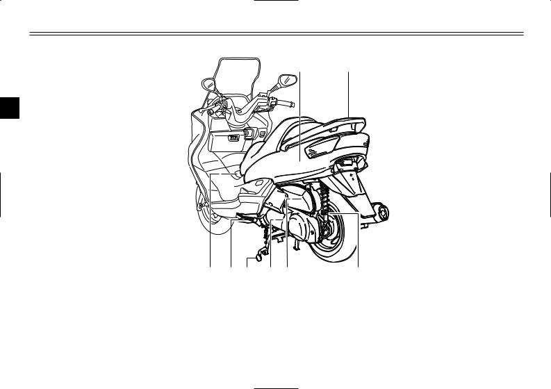
DESCRIPTION
Left view
1 2
2
8 |
7 |
6 |
5 |
4 |
3 |
1. |
Rear storage compartment |
(page 3-18) |
5. |
V-belt case air filter element |
(page 6-22) |
2. |
Grab bar |
(page 5-2) |
6. |
Centerstand |
(page 6-31) |
3. |
Shock absorber spring preload |
|
7. |
Sidestand |
(page 3-20, 6-31) |
|
adjusting ring |
(page 3-19) |
8. |
Fuel tank cap |
(page 3-13) |
4. |
Air filter element |
(page 6-21) |
|
|
|
2-1
DESCRIPTION
Right view |
9 |
10 |
11 |
2 |
12
|
|
|
|
|
|
|
|
|
|
|
|
|
|
|
|
|
|
|
|
|
|
|
|
|
|
|
|
|
|
|
|
|
|
|
|
|
|
|
|
|
|
|
|
|
|
|
|
|
|
|
|
|
|
|
|
|
|
|
|
|
|
|
|
|
|
|
|
|
|
|
|
|
|
|
|
|
|
|
|
|
|
|
|
|
|
|
|
|
|
|
|
18 |
17 |
16 |
15 14 |
13 |
|
||||||||||
9. |
Passenger seat |
|
|
|
|
|
|
|
|
14. |
Battery |
(page 6-34) |
|||||
10. |
Rider seat |
|
|
(page 3-17) |
15. |
Fuse box |
(page 6-36) |
||||||||||
11. |
Air flow louver |
|
|
(page 6-23) |
16. |
Coolant reservoir cap |
(page 6-19) |
||||||||||
12. |
Headlight |
|
|
(page 6-37) |
17. |
Coolant level check window |
(page 6-19) |
||||||||||
13. |
Radiator |
|
|
|
|
|
|
|
|
18. |
Engine oil filler cap |
(page 6-15) |
|||||
2-2
DESCRIPTION
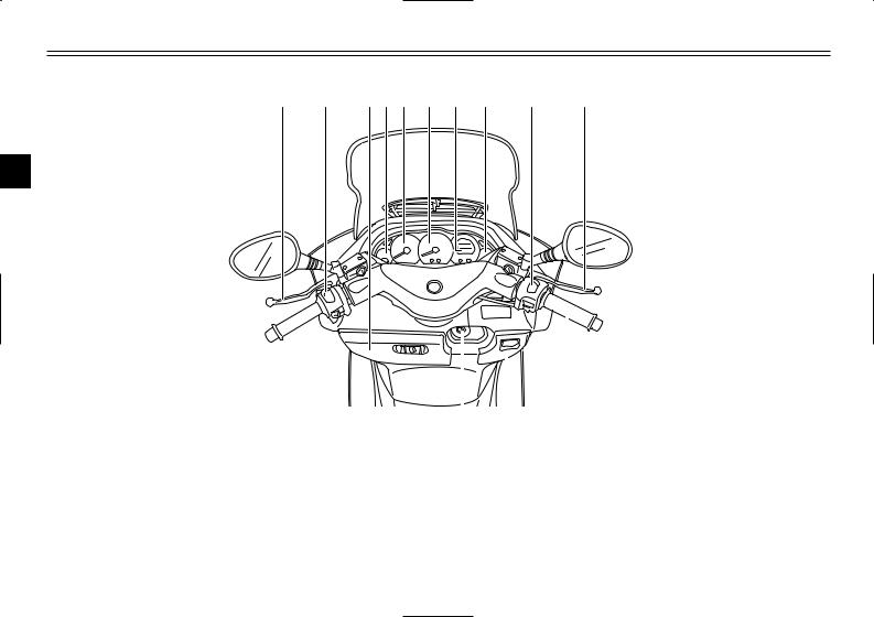
Controls and instruments
1 |
2 |
3 4 |
5 |
6 |
7 |
8 |
9 |
10 |
2
|
|
|
|
|
|
|
|
|
|
|
|
|
|
|
|
|
|
|
|
|
|
|
|
|
|
|
|
|
|
|
|
|
13 |
12 |
11 |
|
|||
1. |
Rear brake lever |
(page 3-13) |
8. |
Fuel gauge |
|
|
(page 3-4) |
||
2. |
Left handlebar switches |
(page 3-10) |
9. |
Right handlebar switches |
(page 3-12) |
||||
3. |
Front storage compartment A |
(page 3-17) |
10. |
Front brake lever |
(page 3-12) |
||||
4. |
Coolant temperature gauge |
(page 3-5) |
11. |
Throttle grip |
|
|
(page 6-23, 6-31) |
||
5. |
Tachometer |
(page 3-3) |
12. |
Front storage compartment B |
(page 3-18) |
||||
6. |
Speedometer |
(page 3-3) |
13. |
Main switch/steering lock |
(page 3-1) |
||||
7. |
Multi-function display |
(page 3-5) |
|
|
|
|
|
|
|
2-3

INSTRUMENT AND CONTROL FUNCTIONS
...................................................................Main switch/steering lock |
3-1 |
|
|
Indicator lights ................................................................................... |
3-2 |
|
|
Speedometer ..................................................................................... |
3-3 |
|
|
Tachometer ....................................................................................... |
3-3 |
|
|
Fuel gauge ......................................................................................... |
3-4 |
|
|
Coolant temperature gauge ............................................................... |
3-5 |
|
3 |
Multi-function display |
3-5 |
|
|
|
|
||
Anti-theft alarm (optional) .................................................................. |
3-9 |
|
|
Handlebar switches ......................................................................... |
3-10 |
|
|
Front brake lever ............................................................................. |
3-12 |
|
|
Rear brake lever .............................................................................. |
3-13 |
|
|
Fuel tank cap ................................................................................... |
3-13 |
|
|
Fuel .................................................................................................. |
3-14 |
|
|
Catalytic converter ........................................................................... |
3-15 |
|
|
Rider seat ........................................................................................ |
3-16 |
|
|
Adjusting the rider seat .................................................................... |
3-17 |
|
|
Storage compartments .................................................................... |
3-17 |
|
|
Adjusting the shock absorber assemblies ....................................... |
3-19 |
|
|
Sidestand ......................................................................................... |
3-20 |
|
|
Ignition circuit cut-off system .......................................................... |
3-21 |
|
|
|
|
|
|
INSTRUMENT AND CONTROL FUNCTIONS
OFF |
ON |
|
|
|
|
|
|
|
|
OPEN |
|
|
|
|
PUSH |
|
|
|
|
LOCK |
|
|
|
N |
PUSH |
|
TO |
||
P |
|
|
||
|
|
I |
I |
|
|
N |
|
|
|
3 |
IG |
|
|
|
|
|
|
|
|
EAU00029
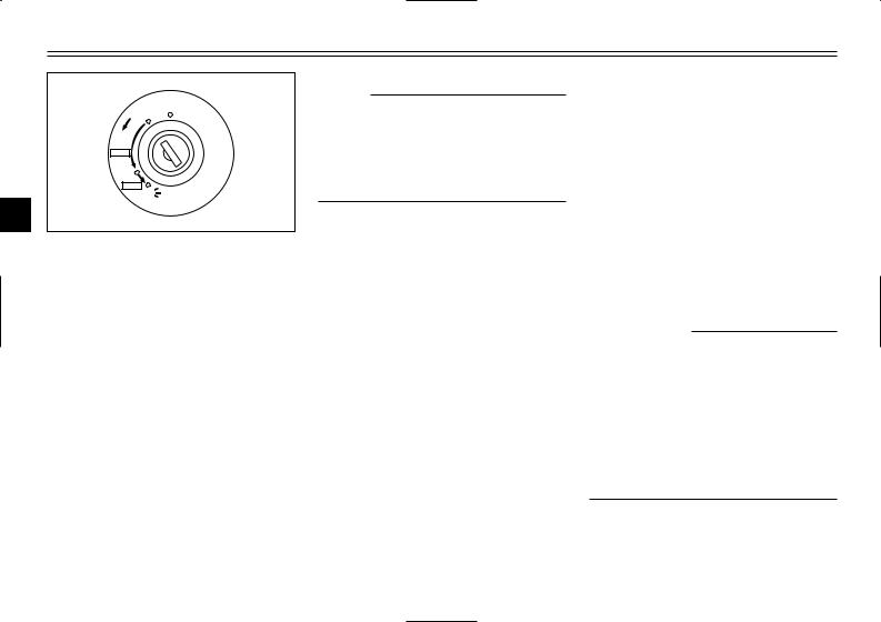
Main switch/steering lock
The main switch/steering lock controls the ignition and lighting systems, and is used to lock the steering. The various positions are described below.
EAU04580
ON
All electrical circuits are supplied with power; the meter lighting, taillight, license plate light and auxiliary light come on, and the engine can be started. The key cannot be removed.
NOTE:
The headlight comes on automatically when the engine is started and stays on until the key is turned to “OFF” or the sidestand is moved down.
EAU00038
OFF
All electrical systems are off. The key can be removed.
EAU00040
LOCK
The steering is locked, and all electrical systems are off. The key can be removed.
EAU00027
To lock the steering
1.Turn the handlebars all the way to the left.
2.Push the key in from the “OFF” position, and then turn it to “LOCK” while still pushing it.
3.Remove the key.
To unlock the steering
Push the key in, and then turn it to “OFF” while still pushing it.
EW000016
w
Never turn the key to “OFF” or “LOCK” while the scooter is moving, otherwise the electrical systems will be switched off, which may result in loss of control or an accident. Make sure that the scooter is stopped before turning the key to “OFF” or “LOCK”.
3-1
INSTRUMENT AND CONTROL FUNCTIONS
EAU03733
. (Parking)
The steering is locked, and the taillight, license light and auxiliary light are on, but all other electrical systems are off. The key can be removed.
To turn the main switch to “.”:
1.Turn the key to “LOCK”.
2.Slightly turn the key counterclockwise until it stops.
3.While still turning the key counterclockwise, push it in until it snaps into place.
ECA00043
cC
Do not use the parking position for an extended length of time, otherwise the battery may discharge.
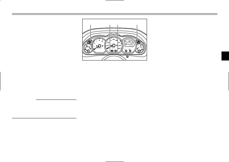
1 |
2 |
3 |
4 |
1.Left turn signal indicator light “4”
2.High beam indicator light “&”
3.Oil change indicator light “7”
4.Right turn signal indicator light “6”
EAU00056
Indicator lights
EAU04121
Turn signal indicator lights “4” and “6”
The corresponding indicator light flashes when the turn signal switch is pushed to the left or right.
EAU00063
High beam indicator light “&”
This indicator light comes on when the high beam of the headlight is switched on.
EAU03734
Oil change indicator light “7”
This indicator light comes on at the initial 1,000 km and every 3,000 km thereafter to indicate that the engine oil should be changed.
If the engine oil is changed before the
oil change indicator comes on (i.e. 3 before the periodic oil change interval
has been reached), the indicator light must be reset after the oil change for the next periodic oil change to be indicated at the correct time. (See page 6-17 for the resetting procedure.)
The electrical circuit of the indicator light can be checked according to the following procedure.
1.Set the engine stop switch to “#” and turn the key to “ON”.
2.Check that the indicator comes on for a few seconds and then goes off.
3.If the indicator light does not come on, have a Yamaha dealer check the electrical circuit.
3-2
INSTRUMENT AND CONTROL FUNCTIONS
NOTE:
The oil change indicator light may flash when the engine is revved with the scooter on the centerstand, but this does not indicate a malfunction.
3
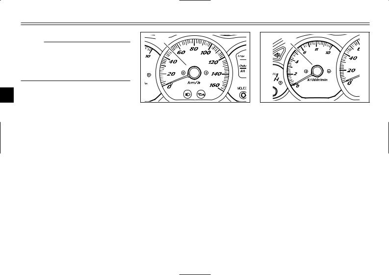
1 |
1. Speedometer
EAU04581
Speedometer
The speedometer shows the riding speed.
When the key is turned to “ON”, the speedometer needle will move to 160 km/h and back to zero in order to test the electrical circuit.
1 |
1. Tachometer
EAU04582
Tachometer
The electric tachometer allows the rider to monitor the engine speed and keep it within the ideal power range.
When the key is turned to “ON”, the tachometer needle will move to the 10,000 r/min and back to zero r/min in order to test the electrical circuit.
3-3
INSTRUMENT AND CONTROL FUNCTIONS
ECA00134
cC
8Do not operate the engine above 8,500 r/min.
8This scooter is equipped with an engine speed limiter, which prevents the engine speed from exceeding approximately 9,000 r/min.
|
1 |
|
3 |
1. |
Fuel gauge |
|
EAU00110 |
Fuel gauge
The fuel gauge indicates the amount of fuel in the fuel tank. The needle moves towards “E” (Empty) as the fuel level decreases. When the needle reaches “E”, approximately 2 L of fuel remain in the fuel tank. If this occurs, refuel as soon as possible.
NOTE:
Do not allow the fuel tank to empty itself completely.
3-4

INSTRUMENT AND CONTROL FUNCTIONS
2 |
1 |
3 |
1.Coolant temperature gauge
2.Red mark
EAU03124
Coolant temperature gauge
This gauge indicates the coolant temperature when the main switch is on. The engine operating temperature will vary with changes in weather and engine load. If the needle points to the red mark, stop your scooter and let the engine cool. (See page 6-44 for details.)
EC000002
cC
Do not operate the engine if it is overheated.
1 |
2 |
3 |
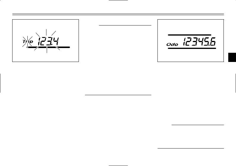
1.Tripmeter
2.Odometer, fuel tripmeter
3.Clock, outside temperature and voltage display
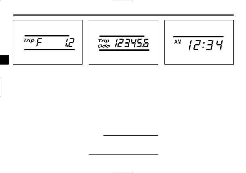
EAU04906
Multi-function display
The multi-function display is equipped with the following:
8a tripmeter (which shows the distance traveled since it was last set to zero)
8a fuel tripmeter (which shows the distance traveled when the fuel
level reaches approximately 2.0 L)
8an odometer (which shows the total distance traveled)
8a clock
8an outside temperature display
|
1 |
2 |
|
|
|
1. |
“SELECT” button |
|
2. |
“RESET” button |
|
8a voltage display (which shows the battery voltage)
NOTE:
8When the key is turned to “ON”, all segments of the display come on for a few seconds. During this time, the multi-function display is performing a self-test.
8Be sure to turn the key to “ON” before using the “SELECT” and “RESET” buttons.
3-5
INSTRUMENT AND CONTROL FUNCTIONS
Tripmeter “Trip”
To reset the tripmeter:
1.Push the “SELECT” button until the voltage display appears, then push the “SELECT” button one more time and “Trip” starts flashing.
2.Push the “RESET” button for at least one second to reset the tripmeter to zero.
NOTE:
8The tripmeter reset mode automatically cancels after five seconds. To return to the reset mode, push the “SELECT” button again until “Trip” begins flashing.
8To cancel the tripmeter reset mode, push the “SELECT” button.
8If the tripmeter indicates “––––”, have a Yamaha dealer check or repair the multi-function display as it may be faulty.
3
Odometer “Odo”
The odometer has two functions.
8It shows the total distance traveled.
8It automatically changes to the fuel tripmeter mode “Trip F” when the fuel level reaches approximately 2.0 L. (See “Fuel tripmeter” for details.)
NOTE:
If the odometer indicates “–––––– ”, have a Yamaha dealer check or repair the multi-function display as it may be faulty.
3-6
INSTRUMENT AND CONTROL FUNCTIONS
3
Fuel tripmeter “Trip F”
When the fuel level reaches approximately 2.0 L, the odometer display automatically changes to the fuel tripmeter mode “Trip F” and starts counting the distance traveled from that point. After refueling and traveling 5 km, the odometer display returns to “Odo”.
To return to the odometer mode before refueling, push the “SELECT” button until “Trip F” begins flashing (“Trip F” will only flash for five seconds). While “Trip F” is flashing, push the “RESET” button for at least one second and the display will return to the odometer mode. From that time, both “Trip” and “Odo” are displayed until you refuel and travel 5 km.
NOTE:
The display cannot be changed back to “Trip F” after pushing the “RESET” button.
Clock
To set the clock
1.Push the “SELECT” button until the clock is displayed.
2.Push the “SELECT” button and “RESET” button together for at least two seconds.
3-7
INSTRUMENT AND CONTROL FUNCTIONS
3
3. When the hour digits start flash- |
4. |
Push the “SELECT” button, and |
Outside temperature display |
ing, push the “RESET” button to |
|
the minute digits will start flashThis display shows the outside tem- |
|
set the hours. |
|
ing. |
perature from -10.0 °C to 50.0 °C in |
|
5. |
Push the “RESET” button to set |
0.5 °C increments. |
|
|
the minutes. |
|
|
6. |
Push the “SELECT” button and |
|
|
|
then release it to start the clock. |
|
3-8
INSTRUMENT AND CONTROL FUNCTIONS
8When the outside temperature falls below -10.0 °C, “– – °C “ is displayed.
8When the outside temperature climbs above 50.0 °C, “50.0” flashes.
3 NOTE:
8If “– – °C” is displayed or “50.0” flashes while the outside temperature is between -10.0 °C and 50.0 °C, there is a problem with the electrical circuit. Have a Yamaha dealer check or repair the electric circuit.
8The accuracy of the temperature reading may be affected when riding slowly (approximately under 20 km/h) or when stopped at traffic signals, railroad crossings, etc.
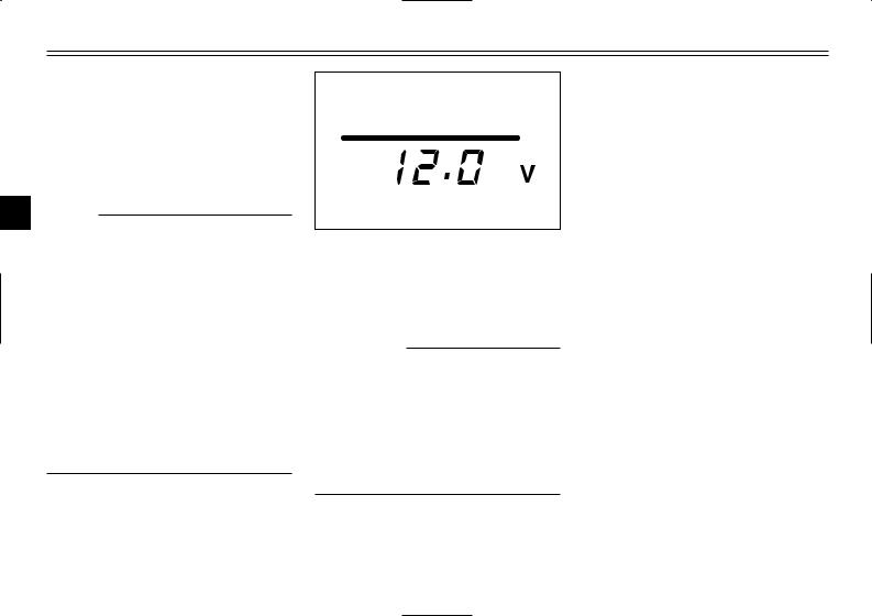
Voltage display
This display shows the battery voltage.
ECA00135
cC
If the voltage display indicates “LO” or “HI”, there may be trouble with the battery charging circuit or the battery may be faulty. If “LO” or “HI” appears in the display, have a Yamaha dealer check or repair the scooter.
EAU00109
Anti-theft alarm (optional)
This scooter can be equipped with an optional anti-theft alarm by a Yamaha dealer. Contact a Yamaha dealer for more information.
3-9
INSTRUMENT AND CONTROL FUNCTIONS
1 |
2 |
3 |
4 |
1.Pass switch “PASS”
2.Dimmer switch “&/%”
3.Turn signal switch “4/6”
4.Horn switch “*”
EAU00118
EAU03889
Turn signal switch “4/6” |
|
|
To signal a right-hand turn, push this |
|
|
switch to “6”. To signal a left-hand |
|
|
turn, push this switch to “4”. When |
|
|
released, the switch returns to the |
|
|
center position. To cancel the turn |
|
|
signal lights, push the switch in after |
3 |
|
it has returned to the center position. |
||
|
||
|
||
EAU00129 |
|
|
Horn switch “*” |
|
|
Press this switch to sound the horn. |
|
Handlebar switches
EAU00120
Pass switch “PASS”
Press this switch to flash the headlight.
EAU03888
Dimmer switch “&/%”
Set this switch to “&” for the high beam and to “%” for the low beam.
3-10
INSTRUMENT AND CONTROL FUNCTIONS
|
|
|
|
|
|
EAU00136 |
|
|
|
|
|
|
|
|
|
Headlight variations |
|
|
|
|
|
3 |
: High beam light on |
2 : Low beam light on |
|||
|
|
|
|
|
|
|
|
|
|
||||
|
|
|
|
|
|
|
|
|
|
' : Auxiliary light on |
1 : Light off |
||
|
|
|
|
|
|
|
|
|
|
|
|
|
|
|
|
|
|
Left |
Right |
|
Aux |
Bulb to |
|
|
|
Destination |
|
|
|
|
|
|
|
|
|
|
|
|
|
|
|
|
|
1 |
% |
2 |
1 |
|
' |
Halogen |
|
12V |
12V |
|
Spain |
|
|
|
|
|
|
|
|
|
Netherlands, |
||||
|
|
& |
1 |
3 |
|
' |
bulb |
|
55W |
60/55W |
|
||
3 |
|
|
|
|
|
|
|||||||
|
|
|
|
|
|
|
|
|
|||||
|
|
|
|
|
|
|
|
|
|
|
|
|
|
|
|
|
% |
1 |
2 |
|
' |
Halogen |
|
12V |
12V |
England |
|
|
|
|
|
||||||||||
|
|
2 |
|
|
|
|
|
|
|
||||
|
|
& |
3 |
1 |
|
' |
bulb |
|
60/55W |
55W |
|
||
|
|
|
|
|
|
|
|||||||
|
|
|
|
|
|
|
|
|
|||||
|
|
|
|
|
|
|
|
|
|
||||
|
|
|
|
|
|
|
|
|
|
|
|
|
|
NOTE:
Right and left are defined as seen when standing in front of the scooter.
3-11
INSTRUMENT AND CONTROL FUNCTIONS
1
2
1.Engine stop switch “#/$”
2.Start switch “,”
EAU03890
Engine stop switch “#/$”
Set this switch to “#” before starting the engine. Set this switch to “$” to stop the engine in case of an emergency, such as when the scooter overturns or when the throttle cable is stuck.
EAU03801
Start switch “,”
With the sidestand up, push this switch while applying the front or rear brake to crank the engine with the starter.
EC000005
cC
See page 5-1 for starting instructions prior to starting the engine.
1
3
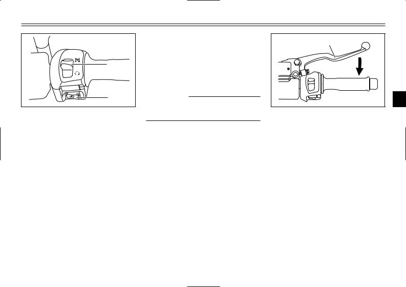
1. Front brake lever
EAU03882
Front brake lever
The front brake lever is located on the right handlebar grip. To apply the front brake, pull this lever toward the handlebar grip.
3-12
INSTRUMENT AND CONTROL FUNCTIONS
1
3
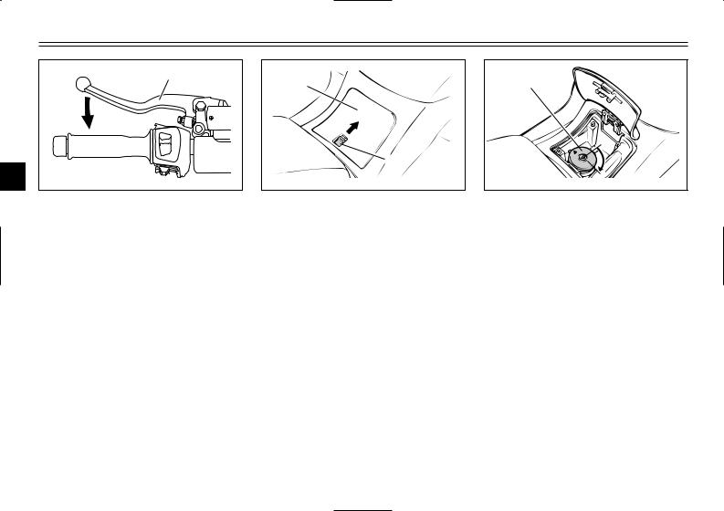
1. Rear brake lever
EAU00163
Rear brake lever
The rear brake lever is located on the left handlebar grip. To apply the rear brake, pull this lever toward the handlebar grip.
1
2
1.Lid
2.Lever
EAU03090
Fuel tank cap
To open the fuel tank cap
1.Open the lid by sliding the lever forward, and then pull the lever up.
1 |
1.Fuel tank cap
2.Insert the key into the lock and turn it clockwise. The lock will be released and the fuel tank cap can be removed.
3-13
 Loading...