

YAMAHA VK540EF ASSEMBLY MANUAL

ASSEMBLY MANUAL
NOTICE D’ASSEMBLAGE
MONTERINGSANVISNING
FOREWORD
This Assembly Manual contains the information
required for proper reassembly of the Yamaha
Snowmobile prior to delivery to the customer.
Since some external parts of the machine have
been removed at the Yamaha factory for packing purpose, assembly by the Y amaha dealer is
required. It should be noted that the reassembled machine should be thoroughly
cleaned, inspected, and adjusted prior to delivery to the purchaser.
NOTICE
The service specifications presented in this
manual may become outdated due to future
changes in this model. Yamaha dealers will be
notified of these changes through technical service information that will be published by Y amaha.
Particularly important information is distinguished in this manual by the following notations.
The Safety Alert Symbol means ATTENTION!
BECOME ALERT! YOUR SAFETY IS INVOLVED!
PREPARATION
To assemble the machine correctly, the pollowing supplies and work space are required:
Supplies
Oils, greases, shop rags.
Workshop
The workshop where the machine is assembled
should be clean and large. The floor should be
level.
Self-protection
Protect your eyes with suitable safety spectacles or safety goggles when using compressed air, when grinding or when doing any
operation which may cause particles to fly off.
Protect hands and feet by wearing safety gloves
or protective shoes if appropriate to the work
you are doing.
Procedure for unpacking
1. To remove the machine and parts packed in
the crate, cut the vinyl bands around the carton using a cutter or scissors. Next, remove
the exterior carton by lifting it straight up.
2. Remove the bolts from each corner of the
rack, and remove the struts.
3. Remove the machine from the bottom board.
4. Before starting the assembly , check for damaged or missing parts. The parts are contained in the carton and the vinyl bags in the
package. Also check the machine for damage, scratches and other defects.
Failure to follow WARNING instructions could
result in severe injury or death to the machine
operator, a bystander , or a person inspecting or
repairing the machine.
CAUTION:
A CAUTION indicates special precautions that
must be taken to avoid damage to the machine.
NOTE:
A NOTE provides key information to make procedures easier or clearer.
UNPACKING
Note on transportation
Take care not to put the machine packed in the
crate against a hard object or subject it to heavy
shocks during transportation or in the service
shop.
VK540E
ASSEMBLY MANUAL
2000 by Yamaha Motor Corporation,
U.S.A.
1st Edition, May 2000
All rights reserved. Any reprinting or
unauthorized use without the written
permission of Yamaha Motor Co., Ltd.
is expressly prohibited.
Printed in Japan

CONTENTS
PARTS LOCATION 1-1. . . . . . . . . . . . . . . . . . . . . . . . . . . . . . . . . . . . . . . . . . . . . . . . . . . . . . . . . . . . . . . .
PARTS LOCATION 1-1. . . . . . . . . . . . . . . . . . . . . . . . . . . . . . . . . . . . . . . . . . . . . . . . . . . . . . . . . . . . . .
REMOVAL FROM CRATE 1-3. . . . . . . . . . . . . . . . . . . . . . . . . . . . . . . . . . . . . . . . . . . . . . . . . . . . . . .
SET UP PROCEDURE 2-1. . . . . . . . . . . . . . . . . . . . . . . . . . . . . . . . . . . . . . . . . . . . . . . . . . . . . . . . . . . . .
HEADLIGHT ASSEMBLY + BACK BUZZER ASSEMBLY 2-1. . . . . . . . . . . . . . . . . . . . . . . . . . . . .
FAIRING 2-3. . . . . . . . . . . . . . . . . . . . . . . . . . . . . . . . . . . . . . . . . . . . . . . . . . . . . . . . . . . . . . . . . . . . . . .
WINDSHIELD ASSEMBLY 2-4. . . . . . . . . . . . . . . . . . . . . . . . . . . . . . . . . . . . . . . . . . . . . . . . . . . . . . .
STEERING ASSEMBLY 2-5. . . . . . . . . . . . . . . . . . . . . . . . . . . . . . . . . . . . . . . . . . . . . . . . . . . . . . . . .
INLET PANEL ASSEMBLY 2-7. . . . . . . . . . . . . . . . . . . . . . . . . . . . . . . . . . . . . . . . . . . . . . . . . . . . . . .
SHIFTER ASSEMBLY 2-8. . . . . . . . . . . . . . . . . . . . . . . . . . . . . . . . . . . . . . . . . . . . . . . . . . . . . . . . . . .
SKI ASSEMBLY 2-9. . . . . . . . . . . . . . . . . . . . . . . . . . . . . . . . . . . . . . . . . . . . . . . . . . . . . . . . . . . . . . . .
FRONT BUMPER ASSEMBLY 2-11. . . . . . . . . . . . . . . . . . . . . . . . . . . . . . . . . . . . . . . . . . . . . . . . . . . .
REAR BUMPER 2-14. . . . . . . . . . . . . . . . . . . . . . . . . . . . . . . . . . . . . . . . . . . . . . . . . . . . . . . . . . . . . . . .
BACKREST ASSEMBLY + ASSIST GRIP ASSEMBLY 2-16. . . . . . . . . . . . . . . . . . . . . . . . . . . . . . .
ADJUSTMENTS AND PREDELIVERY SERVICE 3-1. . . . . . . . . . . . . . . . . . . . . . . . . . . . . . . . . . . . . .
SHEAVE DISTANCE AND OFFSET ADJUSTMENT 3-1. . . . . . . . . . . . . . . . . . . . . . . . . . . . . . . . .
DRIVE V-BELT HEIGHT AND INSTALLATION 3-3. . . . . . . . . . . . . . . . . . . . . . . . . . . . . . . . . . . . . .
BREAK-IN 3-5. . . . . . . . . . . . . . . . . . . . . . . . . . . . . . . . . . . . . . . . . . . . . . . . . . . . . . . . . . . . . . . . . . . . .
ENGINE OIL FILLING 3-6. . . . . . . . . . . . . . . . . . . . . . . . . . . . . . . . . . . . . . . . . . . . . . . . . . . . . . . . . . .
FUEL DRAINING 3-7. . . . . . . . . . . . . . . . . . . . . . . . . . . . . . . . . . . . . . . . . . . . . . . . . . . . . . . . . . . . . . .
DRIVE CHAIN OIL LEVEL 3-7. . . . . . . . . . . . . . . . . . . . . . . . . . . . . . . . . . . . . . . . . . . . . . . . . . . . . . .
OIL PUMP AIR BLEEDING 3-9. . . . . . . . . . . . . . . . . . . . . . . . . . . . . . . . . . . . . . . . . . . . . . . . . . . . . . .
THROTTLE CABLE ADJUSTMENT 3-10. . . . . . . . . . . . . . . . . . . . . . . . . . . . . . . . . . . . . . . . . . . . . . .
OIL PUMP CABLE ADJUSTMENT 3-11. . . . . . . . . . . . . . . . . . . . . . . . . . . . . . . . . . . . . . . . . . . . . . . .
ENGINE IDLE SPEED ADJUSTMENT 3-11. . . . . . . . . . . . . . . . . . . . . . . . . . . . . . . . . . . . . . . . . . . . .
STARTER (CHOKE) CABLE ADJUSTMENT 3-12. . . . . . . . . . . . . . . . . . . . . . . . . . . . . . . . . . . . . . .
BATTERY INSTALLATION 3-13. . . . . . . . . . . . . . . . . . . . . . . . . . . . . . . . . . . . . . . . . . . . . . . . . . . . . . .
TRACK TENSION ADJUSTMENT 3-15. . . . . . . . . . . . . . . . . . . . . . . . . . . . . . . . . . . . . . . . . . . . . . . . .
BRAKE ADJUSTMENT 3-16. . . . . . . . . . . . . . . . . . . . . . . . . . . . . . . . . . . . . . . . . . . . . . . . . . . . . . . . . .
HEADLIGHT BEAM ADJUSTMENT 3-17. . . . . . . . . . . . . . . . . . . . . . . . . . . . . . . . . . . . . . . . . . . . . . .
SKI ADJUSTMENT 3-18. . . . . . . . . . . . . . . . . . . . . . . . . . . . . . . . . . . . . . . . . . . . . . . . . . . . . . . . . . . . . .
REAR SUSPENSION STOPPER BAND TENSION 3-19. . . . . . . . . . . . . . . . . . . . . . . . . . . . . . . . . .
REAR SUSPENSION SPRING PRELORD 3-19. . . . . . . . . . . . . . . . . . . . . . . . . . . . . . . . . . . . . . . . .
FULL RATE ADJUSTMENT 3-20. . . . . . . . . . . . . . . . . . . . . . . . . . . . . . . . . . . . . . . . . . . . . . . . . . . . . .
EXTENSION SPRING PRELOAD 3-21. . . . . . . . . . . . . . . . . . . . . . . . . . . . . . . . . . . . . . . . . . . . . . . . .
APPENDICES 4-1. . . . . . . . . . . . . . . . . . . . . . . . . . . . . . . . . . . . . . . . . . . . . . . . . . . . . . . . . . . . . . . . . . . . .
SERVICE DATA 4-1. . . . . . . . . . . . . . . . . . . . . . . . . . . . . . . . . . . . . . . . . . . . . . . . . . . . . . . . . . . . . . . .
LUBRICATION POINT AND GRADE OF LUBRICANT 5-1. . . . . . . . . . . . . . . . . . . . . . . . . . . . . . . . .
CABLE ROUTING 6-1. . . . . . . . . . . . . . . . . . . . . . . . . . . . . . . . . . . . . . . . . . . . . . . . . . . . . . . . . . . . . . . . .
AVANT-PROPOS
Cette notice d’assemblage contient les informations
nécessaires pour remonter la motoneige Yamaha correctement avant de la livrer au client. Certaines pièces
extérieures du véhicule ayant été enlevées à l’usine Y amaha pour fins d’emballage, le remontage doit être effectué par le concessionnaire Yamaha. A noter que le
véhicule remonté doit être soigneusement nettoyé,
contrôlé et réglé avant d’être livré à l’acheteur.
AVERTISSEMENT
Les caractéristiques d’entretien présentées dans ce manuel pourraient devenir périmées du fait des changements susceptibles d’être apportés à ce modèle. Les
concessionnaires Y amaha seront informés de ces changements par les bulletins techniques publiés par Y amaha.
Dans ce manuel, les informations particulièrement importantes sont repérées par les notations suivantes.
Le symbole d’alerte de sécurité signifie A TTENTION!
SOYEZ VIGILANT! VOTRE SECURITÉ EST EN
JEU!
AVERTISSEMENT
Le non-respect des instructions AVERTISSEMENT
peut entraîner de sérieuses blessures ou la mort
te de la motoneige, d’une personne se trouvant à proximité ou de la personne inspectant ou réparant la motoneige.
du pilo-
PREPARATION
Pour monter correctement la machine, disposer des
fournitures suivantes et d’un lieu de travail approprié.
Fournitures
Huiles, graisses, chiffons d’atelier
Atelier
L’atelier d’assemblage du véhicule doit être propre et
spacieux. Le sol doit être plat.
Protection personnelle
Se protéger les yeux avec des lunettes appropriées ou
des lunettes de protection quand de l’air comprimé est
utilisé, pendant le meulages ou quand il y a risque de
projection de particules.
Se protéger les mains et les pieds en mettant des gants et
des chaussures adaptés si le travail à effectuer le requiert.
Déballage
1. Pour extraire le véhicule et les pièces emballées de
la caisse, couper les bandes de plastique autour du
carton à l’aide d’un couteau ou de ciseaux. Enlever
ensuite le carton extérieur en le soulevant verticalement.
2. Enlever les boulons de chaque côté du bâti et déposer les supports.
3. Déplacer le véhicule de la planche du fond.
4. A vant d’entamer le montage, vérifier qu’il n’y a pas
de pièces endommagées ou manquantes. Les pièces
se trouvent dans le carton et les sachets en plastique
contenus dans l’emballage. S’assurer également
que la machine ne présente pas de détériorations, ni
de rayures ou autres défectuosités.
ATTENTION:
Un ATTENTION indique les procédés spéciaux qui
doivent être suivis pour éviter d’endommager la motoneige.
N.B.:
Un N.B. fournit les renseignements nécessaires pour
rendre les procédés plus faciles ou plus clairs.
DEBALLAGE
Remarque concernant le transport
V eiller à ne pas placer le véhicule emballé dans la caisse
contre un objet dur et ne pas le soumettre à des chocs
importants pendant son transport ou dans l’atelier de
service après-vente.
VK540E
NOTICE D’ASSEMBLAGE
2000 Yamaha Motor Co., Ltd.
re
1
édition, Mai 2000
Tous droits réservés. Toute réimpression
ou utilisation sans la permission écrite
de la Yamaha Motor Co., Ltd.
est formellement interdite.
Imprimé au Japon

SOMMAIRE
EMPLACEMENT DES PIECES 1-1. . . . . . . . . . . . . . . . . . . . . . . . . . . . . . . . . . . . . . . . . . . . . . . . . . . . . . . . . . .
EMPLACEMENT DES PIECES 1-1. . . . . . . . . . . . . . . . . . . . . . . . . . . . . . . . . . . . . . . . . . . . . . . . . . . . . . . . .
DEPOSE DE LA MACHINE 1-3. . . . . . . . . . . . . . . . . . . . . . . . . . . . . . . . . . . . . . . . . . . . . . . . . . . . . . . . . . . .
MONTAGE 2-1. . . . . . . . . . . . . . . . . . . . . . . . . . . . . . . . . . . . . . . . . . . . . . . . . . . . . . . . . . . . . . . . . . . . . . . . . . . . .
ENSEMBLE PHARE AVANT + ENSEMBLE AVERTISSEUR DE MARCHE ARRIERE 2-1. . . . . . . . . . . .
CARENAGE 2-3. . . . . . . . . . . . . . . . . . . . . . . . . . . . . . . . . . . . . . . . . . . . . . . . . . . . . . . . . . . . . . . . . . . . . . . . .
ENSEMBLE PARE-BRISE 2-4. . . . . . . . . . . . . . . . . . . . . . . . . . . . . . . . . . . . . . . . . . . . . . . . . . . . . . . . . . . . .
ENSEMBLE DE DIRECTION 2-5. . . . . . . . . . . . . . . . . . . . . . . . . . . . . . . . . . . . . . . . . . . . . . . . . . . . . . . . . . .
ENSEMBLE PANNEAU D’ADMISSION 2-7. . . . . . . . . . . . . . . . . . . . . . . . . . . . . . . . . . . . . . . . . . . . . . . . . .
ENSEMBLE CHANGEMENT DE VITESSES 2-8. . . . . . . . . . . . . . . . . . . . . . . . . . . . . . . . . . . . . . . . . . . . . .
ENSEMBLE SKI 2-9. . . . . . . . . . . . . . . . . . . . . . . . . . . . . . . . . . . . . . . . . . . . . . . . . . . . . . . . . . . . . . . . . . . . .
ENSEMBLE PARE-CHOCS AVANT 2-11. . . . . . . . . . . . . . . . . . . . . . . . . . . . . . . . . . . . . . . . . . . . . . . . . . . .
PARE-CHOCS ARRIERE 2-14. . . . . . . . . . . . . . . . . . . . . . . . . . . . . . . . . . . . . . . . . . . . . . . . . . . . . . . . . . . . .
ENSEMBLE DOSSIER + ENSEMBLE POIGNEES DE PASSAGER 2-16. . . . . . . . . . . . . . . . . . . . . . . . . . .
REGLAGES ET ENTRETIEN AVANT LIVRAISON 3-1. . . . . . . . . . . . . . . . . . . . . . . . . . . . . . . . . . . . . . . . . .
ECAR TEMENT DES POULIES ET REGLAGE DU DECALAGE 3-1. . . . . . . . . . . . . . . . . . . . . . . . . . . . . .
MONTAGE ET REGLAGE DE HAUTEUR DE LA COURROIE D’ENTRAÎNEMENT 3-3. . . . . . . . . . . . .
RODAGE 3-5. . . . . . . . . . . . . . . . . . . . . . . . . . . . . . . . . . . . . . . . . . . . . . . . . . . . . . . . . . . . . . . . . . . . . . . . . . .
REMPLISSAGE D’HUILE MOTEUR 3-6. . . . . . . . . . . . . . . . . . . . . . . . . . . . . . . . . . . . . . . . . . . . . . . . . . . . .
VIDANGE DE L’ESSENCE 3-7. . . . . . . . . . . . . . . . . . . . . . . . . . . . . . . . . . . . . . . . . . . . . . . . . . . . . . . . . . . . .
NIVEAU D’HUILE DE CHAINE DE TRANSMISSION 3-7. . . . . . . . . . . . . . . . . . . . . . . . . . . . . . . . . . . . . .
PURGE DE L’AIR DE LA POMPE A HUILE 3-9. . . . . . . . . . . . . . . . . . . . . . . . . . . . . . . . . . . . . . . . . . . . . .
REGLAGE DU CABLE D’ACCELERATEUR 3-10. . . . . . . . . . . . . . . . . . . . . . . . . . . . . . . . . . . . . . . . . . . . .
REGLAGE DU CABLE DE LA POMPE A HUILE 3-11. . . . . . . . . . . . . . . . . . . . . . . . . . . . . . . . . . . . . . . . .
REGLAGE DU RALENTI 3-11. . . . . . . . . . . . . . . . . . . . . . . . . . . . . . . . . . . . . . . . . . . . . . . . . . . . . . . . . . . . .
REGLAGE DU JEU DU CABLE DE STARTER (enrichisseyr) 3-12. . . . . . . . . . . . . . . . . . . . . . . . . . . . . . . .
MONTAGE DE LA BATTERIE 3-13. . . . . . . . . . . . . . . . . . . . . . . . . . . . . . . . . . . . . . . . . . . . . . . . . . . . . . . . .
REGLAGE DE LA TENSION DE LA CHENILLE 3-15. . . . . . . . . . . . . . . . . . . . . . . . . . . . . . . . . . . . . . . . .
REGLAGE DU FREIN 3-16. . . . . . . . . . . . . . . . . . . . . . . . . . . . . . . . . . . . . . . . . . . . . . . . . . . . . . . . . . . . . . . .
REGLAGE DU FAISCEAU DE PHARE AVANT 3-17. . . . . . . . . . . . . . . . . . . . . . . . . . . . . . . . . . . . . . . . . . .
REGLAGE DES SKIS 3-18. . . . . . . . . . . . . . . . . . . . . . . . . . . . . . . . . . . . . . . . . . . . . . . . . . . . . . . . . . . . . . . .
TENSION DE LA SANGLE D’ARRET DE LA SUSPENSION 3-19. . . . . . . . . . . . . . . . . . . . . . . . . . . . . . .
PRECONTRAINTE DE RESSORT DE LA SUSPENSION 3-19. . . . . . . . . . . . . . . . . . . . . . . . . . . . . . . . . . .
AJUSTEMENT DE LA CONSTANTE DE RAPPEL 3-20. . . . . . . . . . . . . . . . . . . . . . . . . . . . . . . . . . . . . . . .
PRECHARGE D’EXTENSION DE RESSORT 3-21. . . . . . . . . . . . . . . . . . . . . . . . . . . . . . . . . . . . . . . . . . . . .
APPENDICES 4-1. . . . . . . . . . . . . . . . . . . . . . . . . . . . . . . . . . . . . . . . . . . . . . . . . . . . . . . . . . . . . . . . . . . . . . . . . .
CARACTERISTIQUES D’ENTRETIEN 4-1. . . . . . . . . . . . . . . . . . . . . . . . . . . . . . . . . . . . . . . . . . . . . . . . . . .
POINT DE LUBRIFICATION ET TYPE DE LUBRIFIANT 5-1. . . . . . . . . . . . . . . . . . . . . . . . . . . . . . . . . . . .
CHEMINEMENT DES CABLES 6-1. . . . . . . . . . . . . . . . . . . . . . . . . . . . . . . . . . . . . . . . . . . . . . . . . . . . . . . . . .

FÖRORD
Denna monteringsanvisning innehåller den information som behövs för att sätta ihop Yamahas
snöskoter på korrekt sätt innan den levereras till
kunden. Eftersom några av maskinens yttre delar
har demonterats på fabriken för att underlätta
nedpackning, så krävs att viss ihopmontering
görs av Yamaha-återförsäljaren.
Lägg märke till att maskinen bör vara väl rengjord,
kontrollerad och justerad innan den levereras till
kunden.
OBS !
Servicespecifikationerna i denna manual kan bli
inaktuella p.g.a. framtida förändringar av modellen. Y amahas återförsäljare kommer att uppmärksammas på dessa förändringar genom den tekniska serviceinformation som publiceras av
Yamaha.
Särskilt viktig information i denna monteringsanvisning har markerats på något av följande sätt:
Varningstriangeln betyder: SE UPP! VAR FÖRSIKTIG! DET GÄLLER DIN SÄKERHET!
VARNING
Om dessa anvisningar inte följs, kan det medföra
risk för föraren, en förbipasserande eller en person, som kontrollerar eller reparerar maskinen, eller resultera i skada eller dödsfall.
FÖRBEREDELSER
För att maskinen ska kunna monteras ihop på korrekt sätt måste följande krav på utrustning och arbetsutrymme uppfyllas:
Utrustning
Oljor, fetter, trasor.
Arbetsutrymme
Verkstaden där maskinen skall monteras måste
vara rengjord och stor. Golvet skall vara plant.
Skyddskläder
Använd lämpliga skyddsglasögon för att skydda
ögonen när arbetet kräver att trycklyft används
under arbetets gång. Använd också skyddsglasögon vid slipning o. s. v . för att skydda ögonen mot
damm och andra partiklar som flyger i luften.
Ha på dig lämpliga skyddskläder, som till exempel
skyddshandskar och tjocka skor, enligt det arbete
som skall utföras.
Arbetsgång vid uppackning
1. Skär av plastbanden som omsluter lådan.
Tag sedan bort den yttre kartongen genom att
lyfta den rätt upp.
2. Demontera bultarna från hörnen på ställningen. Demontera tvärslåarna.
3. Ta loss maskinen från bottenplattan.
4. Kontrollera, före hopsättningsstart, att inga delar är skadade eller saknas. Delarna är förpackade i kartongen och plastpåsarna. Kontrollera också att maskinen inte är skadad,
repad eller bristfällig på annat sätt.
VIKTIGT:
Anvisningarna under denna rubrik måste följas för
att inte maskinen skall skadas.
OBS:
Ger information som gör handhavandet enklare.
UPPACKNING
Att observera vid uppackning
Se till att den låda som maskinen är förpackad i inte skaver mot något hårt föremål eller utsätts för
stötar under transport eller i serviceverkstaden.
VK540E
MONTERINGSANVISNING
2000 av Yamaha Motor Co., Ltd.
1:a upplagan, maj 2000
Alla rättigheter förbehållna.
Varje slag av eftertryck
eller annat obehörigt utnyttjande utan
skriftlig tillåtelse från
Yamaha Motor Co., Ltd.
är uttryckligen förbjudet.
Tryckt i Japan

INNEHÅLL
DETALJFÖRTECKNING 1-1. . . . . . . . . . . . . . . . . . . . . . . . . . . . . . . . . . . . . . . . . . . . . . . . . . . . . . . . . . . . . . . . .
DET ALJFÖRTECKNING 1-1. . . . . . . . . . . . . . . . . . . . . . . . . . . . . . . . . . . . . . . . . . . . . . . . . . . . . . . . . . . . . .
ATT PACKA UPP SNÖSKOTERN 1-3. . . . . . . . . . . . . . . . . . . . . . . . . . . . . . . . . . . . . . . . . . . . . . . . . . . . . .
MONTERING 2-1. . . . . . . . . . . . . . . . . . . . . . . . . . . . . . . . . . . . . . . . . . . . . . . . . . . . . . . . . . . . . . . . . . . . . . . . . . .
MONTERING A V STRÅLKASTARE + BACKSUMMER 2-1. . . . . . . . . . . . . . . . . . . . . . . . . . . . . . . . . . . .
MONTERING AV STRÖMLINJEPLÅT 2-3. . . . . . . . . . . . . . . . . . . . . . . . . . . . . . . . . . . . . . . . . . . . . . . . . .
MONTERING AV VINDRUTA 2-4. . . . . . . . . . . . . . . . . . . . . . . . . . . . . . . . . . . . . . . . . . . . . . . . . . . . . . . . . .
MONTERING AV STYRE 2-5. . . . . . . . . . . . . . . . . . . . . . . . . . . . . . . . . . . . . . . . . . . . . . . . . . . . . . . . . . . . .
MONTERING AV INTAGSPLÅT 2-7. . . . . . . . . . . . . . . . . . . . . . . . . . . . . . . . . . . . . . . . . . . . . . . . . . . . . . . .
MONTERING AV VÄXLINGSENHET 2-8. . . . . . . . . . . . . . . . . . . . . . . . . . . . . . . . . . . . . . . . . . . . . . . . . . .
MONTERING AV SKIDOR 2-9. . . . . . . . . . . . . . . . . . . . . . . . . . . . . . . . . . . . . . . . . . . . . . . . . . . . . . . . . . . .
MONTERING AV FRÄMRE STÖTFÅNGARE 2-11. . . . . . . . . . . . . . . . . . . . . . . . . . . . . . . . . . . . . . . . . . .
MONTERING A V BAKRE STÖTFÅNGARE 2-14. . . . . . . . . . . . . . . . . . . . . . . . . . . . . . . . . . . . . . . . . . . . .
MONTERING AV RYGGSTÖD + ST ÖDHANDTAG 2-16. . . . . . . . . . . . . . . . . . . . . . . . . . . . . . . . . . . . . .
JUSTERINGAR OCH SERVICE FÖRE LEVERANS 3-1. . . . . . . . . . . . . . . . . . . . . . . . . . . . . . . . . . . . . . . . .
JUSTERING AV SKIVAVSTÅND OCH SIDOFÖRSKJUTNING 3-1. . . . . . . . . . . . . . . . . . . . . . . . . . . . .
MONTERING AV VARIATORREM OCH INSTÄLLING AV DESS HÖJD 3-3. . . . . . . . . . . . . . . . . . . . . .
INKÖRNING 3-5. . . . . . . . . . . . . . . . . . . . . . . . . . . . . . . . . . . . . . . . . . . . . . . . . . . . . . . . . . . . . . . . . . . . . . . .
PÅFYLLNING AV MOTOROLJA 3-6. . . . . . . . . . . . . . . . . . . . . . . . . . . . . . . . . . . . . . . . . . . . . . . . . . . . . . .
ATT TAPPA AV BRÄNSLE 3-7. . . . . . . . . . . . . . . . . . . . . . . . . . . . . . . . . . . . . . . . . . . . . . . . . . . . . . . . . . . .
DRIVKEDJEHUSETS OLJENIVÅ 3-7. . . . . . . . . . . . . . . . . . . . . . . . . . . . . . . . . . . . . . . . . . . . . . . . . . . . . .
LUFTNING AV OLJEPUMP 3-9. . . . . . . . . . . . . . . . . . . . . . . . . . . . . . . . . . . . . . . . . . . . . . . . . . . . . . . . . . .
JUSTERING AV GASVAJER 3-10. . . . . . . . . . . . . . . . . . . . . . . . . . . . . . . . . . . . . . . . . . . . . . . . . . . . . . . . .
JUSTERING AV OLJEPUMPSVAJER 3-11. . . . . . . . . . . . . . . . . . . . . . . . . . . . . . . . . . . . . . . . . . . . . . . . .
JUSTERING AV MOTORNS TOMGÅNGSVARVTAL 3-11. . . . . . . . . . . . . . . . . . . . . . . . . . . . . . . . . . . . .
JUSTERING AV STARTVAJER (CHOKE) 3-12. . . . . . . . . . . . . . . . . . . . . . . . . . . . . . . . . . . . . . . . . . . . . .
BA TTERIINST ALLATION 3-13. . . . . . . . . . . . . . . . . . . . . . . . . . . . . . . . . . . . . . . . . . . . . . . . . . . . . . . . . . . . .
DRIVBANDSJUSTERING 3-15. . . . . . . . . . . . . . . . . . . . . . . . . . . . . . . . . . . . . . . . . . . . . . . . . . . . . . . . . . . .
BROMSJUSTERING 3-16. . . . . . . . . . . . . . . . . . . . . . . . . . . . . . . . . . . . . . . . . . . . . . . . . . . . . . . . . . . . . . . .
STRÅLKASTARINSTÄLLNING 3-17. . . . . . . . . . . . . . . . . . . . . . . . . . . . . . . . . . . . . . . . . . . . . . . . . . . . . . .
JUSTERING AV SKIDORNA 3-18. . . . . . . . . . . . . . . . . . . . . . . . . . . . . . . . . . . . . . . . . . . . . . . . . . . . . . . . .
BAKRE UPPHÄNGNINGENS STOPPARBANDSSPÄNNING 3-19. . . . . . . . . . . . . . . . . . . . . . . . . . . . .
FJÄDERBELASTNING FÖR BAKRE UPPHÄNGNING 3-19. . . . . . . . . . . . . . . . . . . . . . . . . . . . . . . . . . .
TOT ALJUSTERING 3-20. . . . . . . . . . . . . . . . . . . . . . . . . . . . . . . . . . . . . . . . . . . . . . . . . . . . . . . . . . . . . . . . .
FJÄDERNS FÖRBELASTNING 3-21. . . . . . . . . . . . . . . . . . . . . . . . . . . . . . . . . . . . . . . . . . . . . . . . . . . . . . .
BILAGA 4-1. . . . . . . . . . . . . . . . . . . . . . . . . . . . . . . . . . . . . . . . . . . . . . . . . . . . . . . . . . . . . . . . . . . . . . . . . . . . . . .
SPECIFIKA TIONER 4-1. . . . . . . . . . . . . . . . . . . . . . . . . . . . . . . . . . . . . . . . . . . . . . . . . . . . . . . . . . . . . . . . . .
SMÖRJPUNKTER OCH SMÖRJMEDEL 5-1. . . . . . . . . . . . . . . . . . . . . . . . . . . . . . . . . . . . . . . . . . . . . . . . . . .
KABELDRAGNINGSSCHEMA 6-1. . . . . . . . . . . . . . . . . . . . . . . . . . . . . . . . . . . . . . . . . . . . . . . . . . . . . . . . . . .
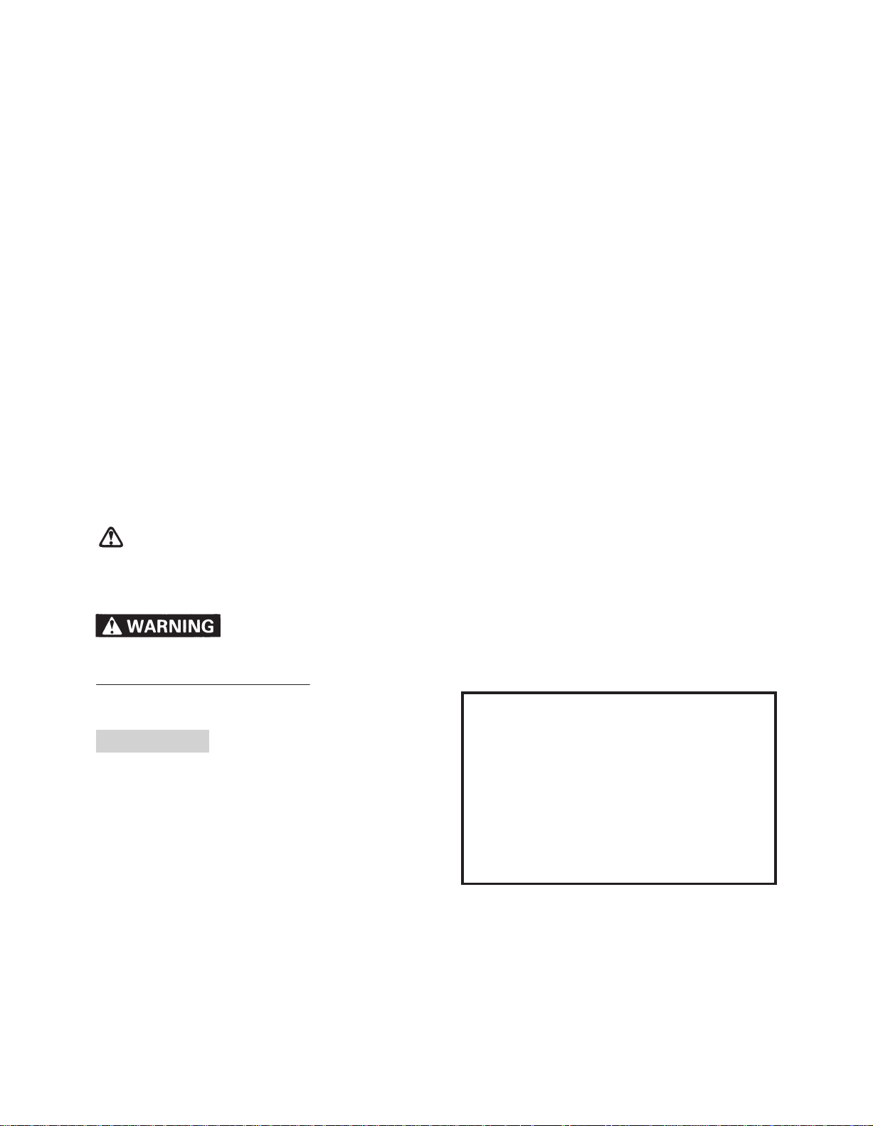
PARTS LOCATION
PARTS LOCATION
Vinyl bag
A
Carton box
B
Carton box
C
Carton box
D
Carton box
E
Rear bumper
F
Windshield
G
Shifter assembly
H
Front bumper
I
Vinyl bag
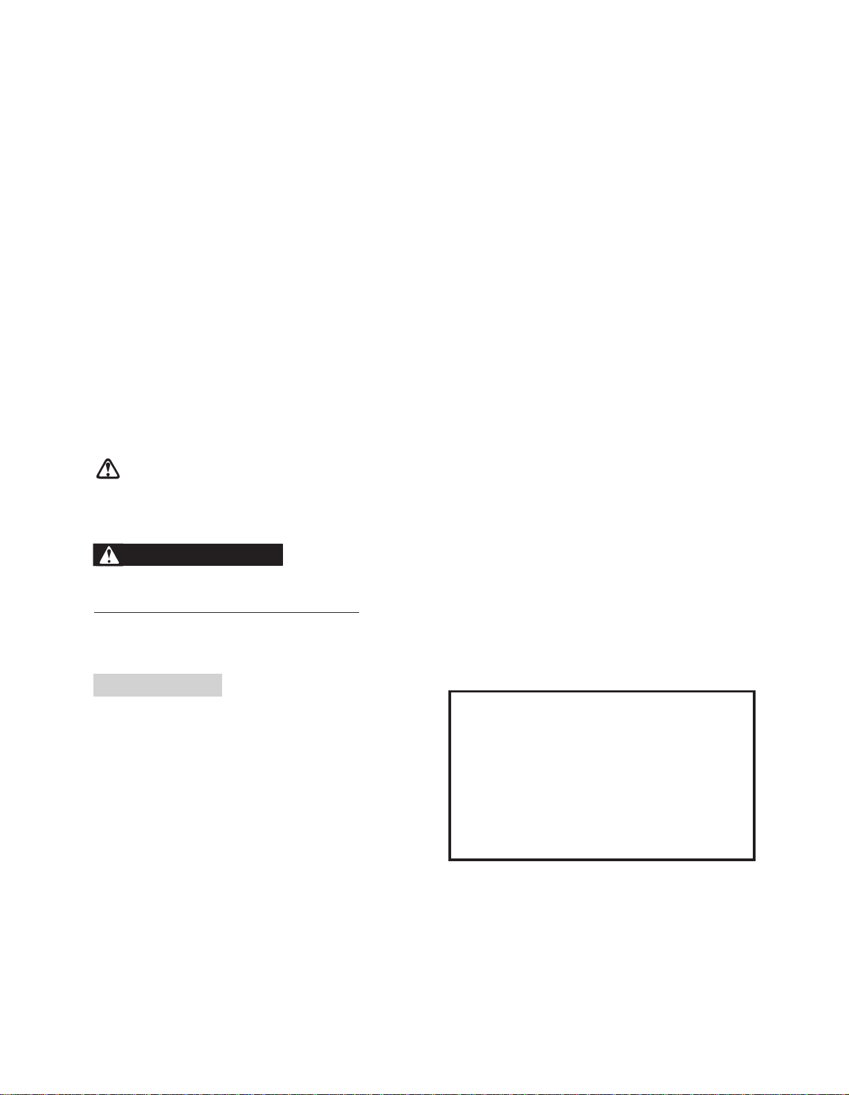
A
1
B
Carton box
3
Tool box
12
3
Spacer
13
Joint
Key Handle holder upper Handle holder lower
4
Spanner
(10 – 12)
Box
5
wrench
(14)
2
1
Ski
8
Screw
driver bit
+
9
Grip
–
2
Vinyl bag 1 6
4
Bolts
18
Owner’s Manual
19
Safety hand book
20
Grommet
6
Spanner
(14 – 17)
7
Box
wrench
(17 – 21)
10
Spanner
(19 – 22)
11
Spanner
(8 – 10)
14
16
1-1
Spacer
Bracket
15
Battery hose
17
Band
21
Shifter cover

EMPLACEMENT DES PIECES
EMPLACEMENT DES PIECES
Sachet en plastique
A
Boîte en carton
B
Boîte en carton
C
Boîte en carton
D
Boîte en carton
E
Pare-chocs arrière
F
Pare-brise
G
Ensemble changement de vitesses
H
Pare-chocs avant
I
DETALJFÖRTECKNING
DETALJFÖRTECKNING
Plastpåse
A
Kartong
B
Kartong
C
Kartong
D
Kartong
E
Bakre stötfångare
F
Vindruta
G
Växlingsenhet
H
Främre stötfångare
I
Sachet en plastique
A
Clé
1
Support supérieur de guidon
2
Support inférieur de guidon
3
Boulons
4
Boîte en carton
B
Ski
1
Sachet en plastique n1 6
2
Boîte à outils
3
Clé plate (10-12)
4
Clé à douille (14)
5
Clé plate (14-17)
6
Clé à douille (17-21)
7
8
Mèche de tournevis
Poignée
9
Clé plate (19-22)
10
Clé plate (8-10)
11
Entretoise
12
Joint
13
Entretoise
14
Tuyau de batterie
15
Support
16
Collier
17
Manuel du propriétaire
18
Livret de consignes de sécurité
19
Rondelle en caoutchouc
20
Couvercle changement de vitesses
21
+
–
Plastpåse
A
Nyckel
1
Styrklämmor, övre
2
Styrklämma, nedre
3
Bultar
4
Kartong
B
Skidor
1
Plastpåse nr. 1 6
2
Verktygslåda
3
Skruvnyckel (10-12)
4
Hylsnyckel (14)
5
Skruvnyckel (14-17)
6
Hylsnyckel (17-21)
7
8
Skruvmejsel, bit
Grepp
9
Skruvnyckel (19-22)
10
Skruvnyckel (8-10)
11
Mellanlägg
12
Led
13
Mellanlägg
14
Batterislang
15
Fäste
16
Band
17
Bruksanvisning
18
Säkerhetsanvisningar
19
Genomföring
20
Växelkåpa
21
+
–
1-1
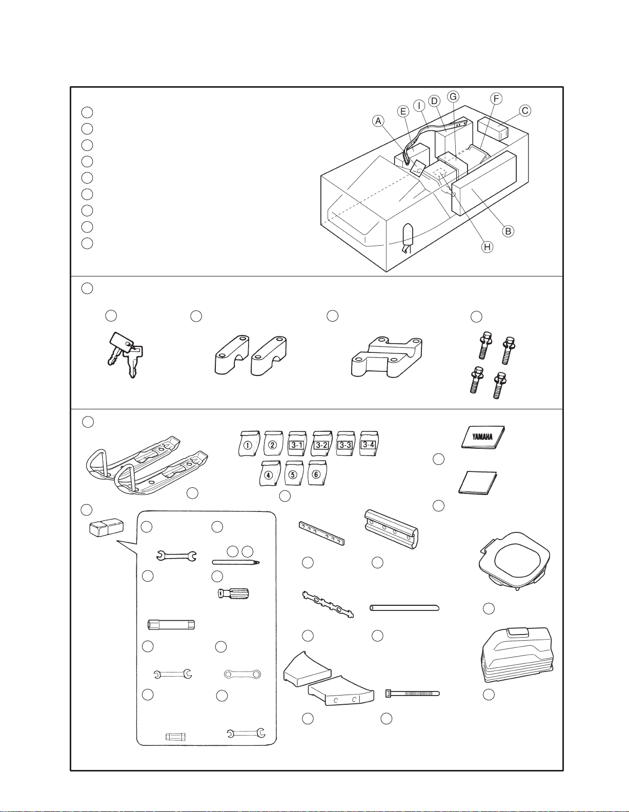
Carton box
C
1
Headlight assembly
Carton box
E
D
Carton box
1
Fairing
F
Rear bumper
1
Backrest
7
Bumper rubber
Under the seat
H
2
Assist grip
4
Inlet panel
6
Bumper protector
3
Back buzzer assembly
G
Windshield
I
Front bumper
5
Steering pad
1
Shifter assembly
2
Hexagon bolt
1-2
3
Washer
4
Nut

Boîte en carton
C
Ensemble phare avant
1
Kartong
C
Strålkastare
1
Boîte en carton
D
Carénage
1
Pare-chocs arrière
F
Boîte en carton
E
Dossier
1
Poignée de sécurité
2
Ensemble avertisseur marche arrière
3
Panneau d’admission en collier
4
Rembourrage de direction
5
Protection de pare-chocs
6
Couverture caoutchouc de pare-chocs
7
Pare-brise
G
Kartong
D
Strömlinjeplåt
1
Bakre stötfångare
F
Kartong
E
Ryggstöd
1
Stödhandtag
2
Backsummer
3
Intagsplåt
4
Styrkåpa
5
Stötfångarskydd
6
Stötfångargummi
7
Vindruta
G
Pare-chocs avant
I
Sous le siège
H
Ensemble changement de vitesses
1
Boulon hexagonal
2
Rondelle
3
Ecrou
4
Främre stötfångare
I
Under sätet
H
Växlingsenhet
1
Sexkantsbultar
2
Brickor
3
Muttrar
4
1-2
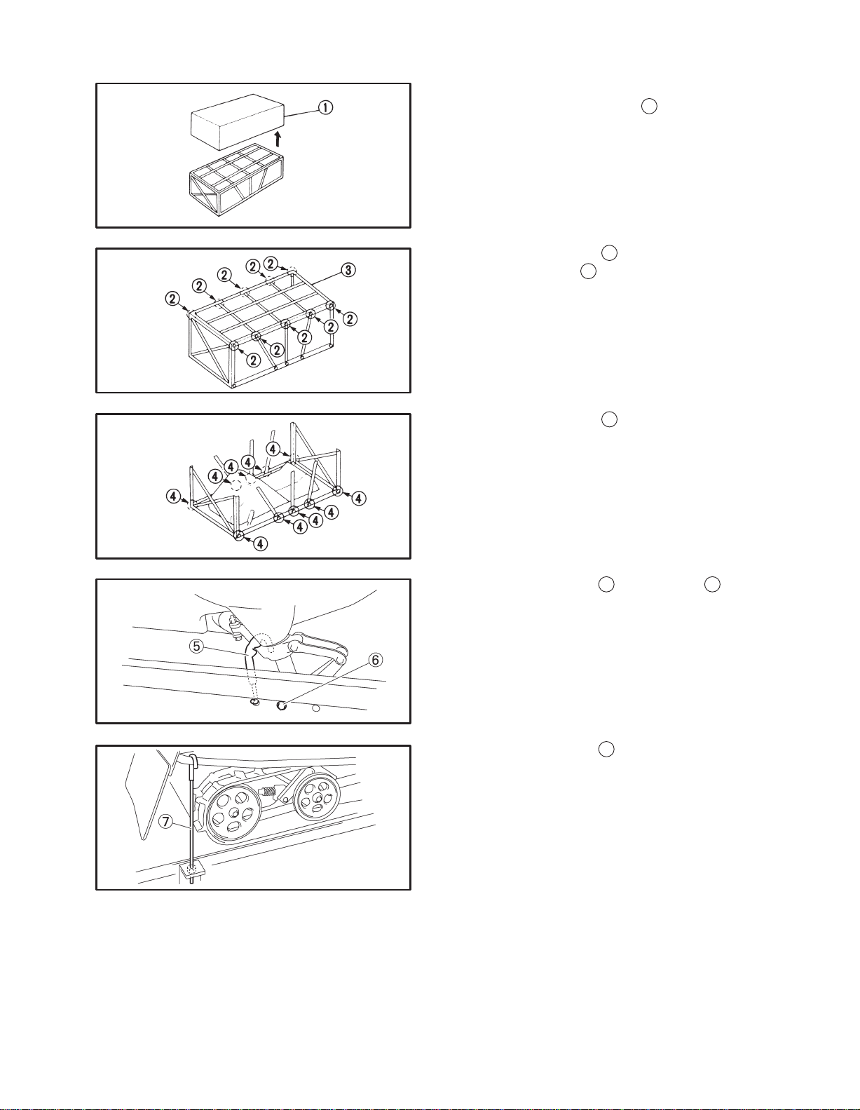
REMOVAL FROM CRATE
1. Remove the crate cover
2
2. Remove the bolts
top of the crate
3. Remove the bolts
and then remove the
3
.
4
and then remove the
sides of the crate.
4. Remove the carton box.
1
.
5. Remove the hook
(Both sides)
6. Remove the hook
(Both sides)
5
and the bolt 6.
7
.
1-3

DEPOSE DE LA MACHINE
1. Déposer le couvercle de la caisse
1 .
ATT PACKA UPP SNÖSKOTERN
1. Lyft av det yttersta transportskyddet
1.
2. Retirer les boulons
caisse
3 .
3. Retirer les boulons
2 puis déposer le dessus de la
4 puis déposer les côtés de la
caisse.
4. Enlever la boîte en carton.
5. Détacher le crochet
5 et le boulon de fixation 6 .
(Des deux côtés)
2. Avlägsna bultarna
delen av ställningen
3. Avlägsna bultarna
na av ställningen.
4. Ta ur kartongerna.
5. Tag bort haken
5 och bulten 6 . (på båda si-
dor)
2 och ta därefter loss övre
3.
4 och ta därefter loss sidor-
6. Détacher le crochet
7 . (Des deux côtés)
6. Ta bort haken
1-3
7 . (på båda sidor)
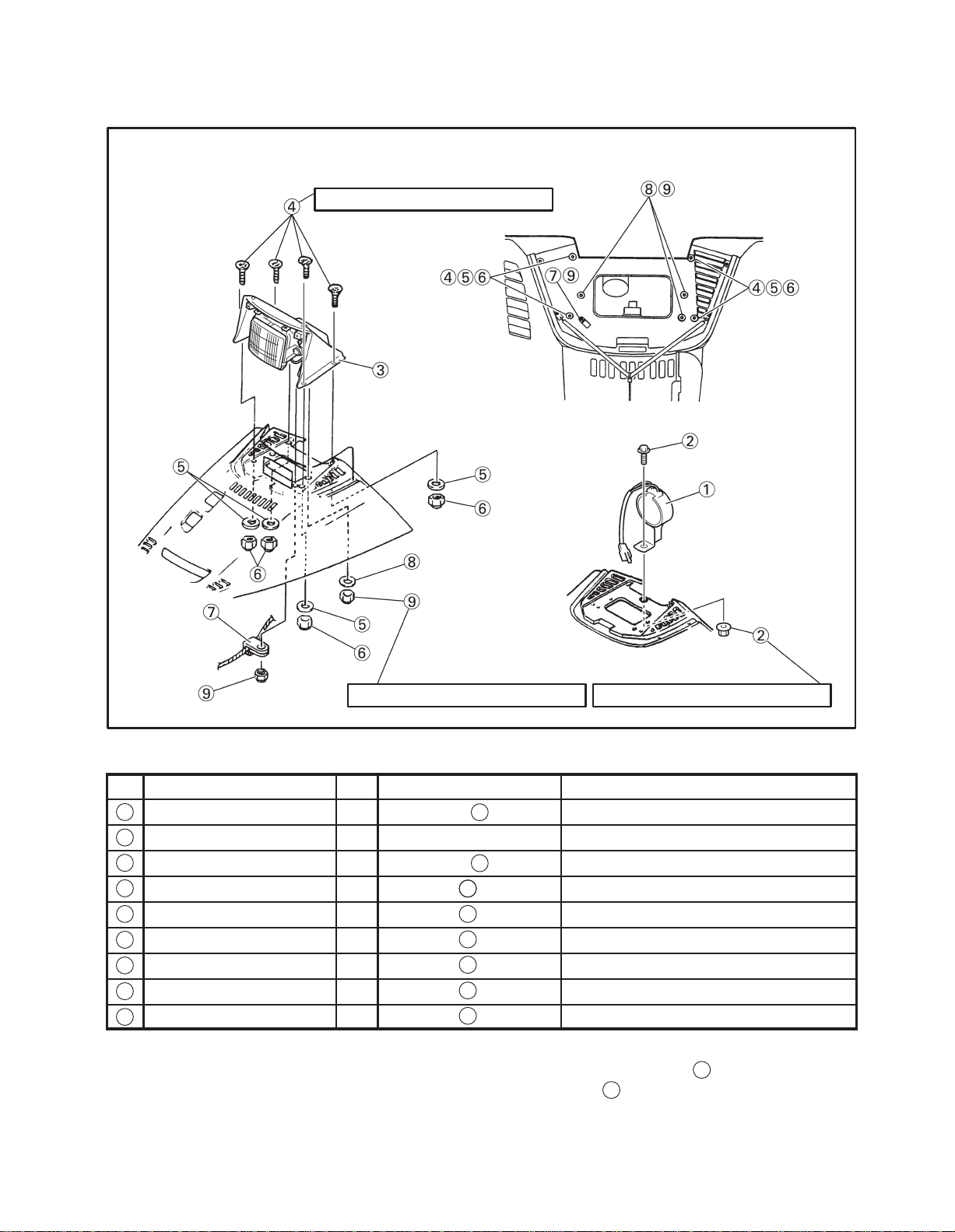
SET UP PROCEDURE
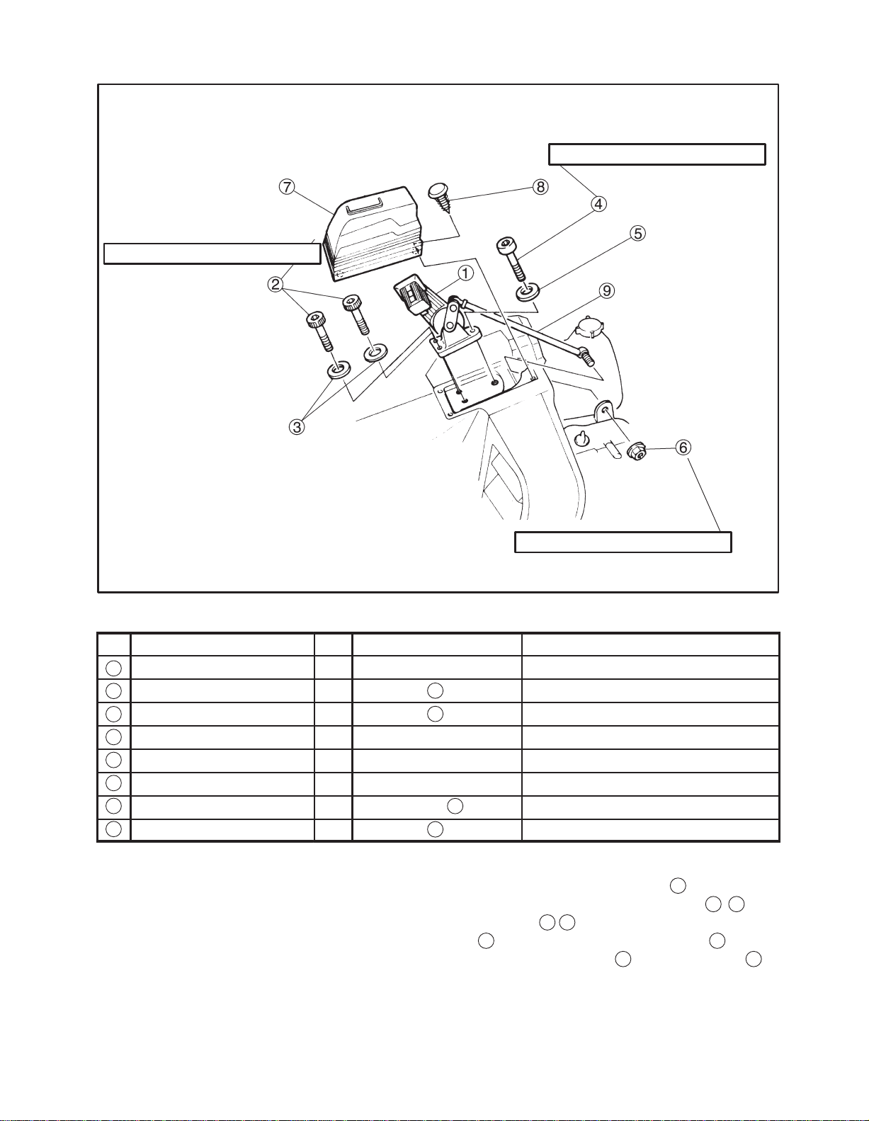
HEADLIGHT ASSEMBLY + BACK BUZZER ASSEMBLY
2 Nm (0.2 mkg, 1.4 ftlb)
5 Nm (0.5 mkg, 3.6 ftlb)5 Nm (0.5 mkg, 3.6 ftlb)
Parts List
No Parts Name Qty Location Remark
Back buzzer 1 Carton box “ ”
1
Bolt & Nut 1+1 Installed to the buzzer
2
Headlight assembly 1 Carton box “ ”
3
Screw 4 Vinyl bag “ ” M5 0.8 =16 mm (0.63 in)
4
Washer 4 Vinyl bag “ ” D=14 mm (0.55 in) d=5.5 mm (0.21 in)
5
Nut 4 Vinyl bag “ ” M5 0.8
6
Clamp 1 Vinyl bag “ ”
7
Washer 3 Vinyl bag “ ” D=18 mm (0.7 in) d=6 mm (0.24 in)
8
Nut 4 Vinyl bag “ ” M 6 1.0
9
E
C
55
5
5
5
5
5
Set up point
1
1. Install the back buzzer
bolt & nut
2
.
to the shroud using
2-1
MONTAGE
ENSEMBLE PHARE AVANT + ENSEMBLE AVERTISSEUR DE MARCHE ARRIERE
Liste des pièces
N_
1
2
3
4
5
6
7
8
9
Nom des pièces Qté Emplacement Remarque
Avertisseur marche arrière 1 Boîte en carton “ ”
Boulon & Ecrou 1+1 Dans l’avertisseur
Ensemble phare avant 1 Boîte en carton “ ”
Vis 4 Sachet en vinyle “ ” M5 0,8 = 16 mm (0,63 in)
Rondelle 4 Sachet en vinyle “ ” D = 14 mm (0,55 in) d = 5,5 mm (0.21 in)
Ecrou 4 Sachet en vinyle “ ” M5 0,8
Fixation 1 Sachet en vinyle “ ”
Rondelle 3 Sachet en vinyle “ ” D = 18 mm (0,7 in) d = 6 mm (0,24 in)
Ecrou 4 Sachet en vinyle “ ” M6 1,0
MONTERING
MONTERING AV STRÅLKASTARE + BACKSUMMER
Detaljförteckning
Nr
Backsummer 1 Kartong “ ”
1
Bult & mutter 1+1 Monterad på summern
2
Strålkastare 1 Kartong “ ”
3
Detalj Ant Placering Anmärkning
E
C
E
C
5
5
5
5
5
5
Skruv 4 Plastpåse “ ” M5 0,8 = 16 mm (0,63 in)
4
Bricka 4 Plastpåse “ ” D = 14 mm (0,55 in) d = 5,5 mm (0,21 in)
5
Mutter 4 Plastpåse “ ” M5 0,8
6
Klämma 1 Plastpåse “ ”
7
8
Bricka 3 Plastpåse “ ” D = 18 mm (0,7 in) d = 6 mm (0,24 in)
9
Mutter 4 Plastpåse “ ” M6 1,0
Point de montage
1. Installer l’avertisseur de marche arrière
tôle de protection à l’aide du boulon et de l’écrou
2 .
1 sur la
5
5
5
5
5
5
Monteringsåtgärde
1. Montera backsummern
bult och mutter
1 i höljet med hjälp av
2.
2-1

2. Install the headlight assembly 3 to the
7
shroud with clamp
washers
5 8
and nylon nuts 6 (M5)
using screws 4,
9
(M6).
2-2

2. Fixer l’ensemble phare avant 3 sur la tôle de pro-
tection avec la fixation
rondelles
5 8 et des écrous en nylon 6 (M5) 9
7 à l’aide des vis 4 , des
(M6).
2. Montera strålkastaren
3 i höljet med klämman
7 med hjälp av skruvarna 4 , brickorna 5 8
och nylonmuttrarna
6 (M5) 9 (M6).
2-2
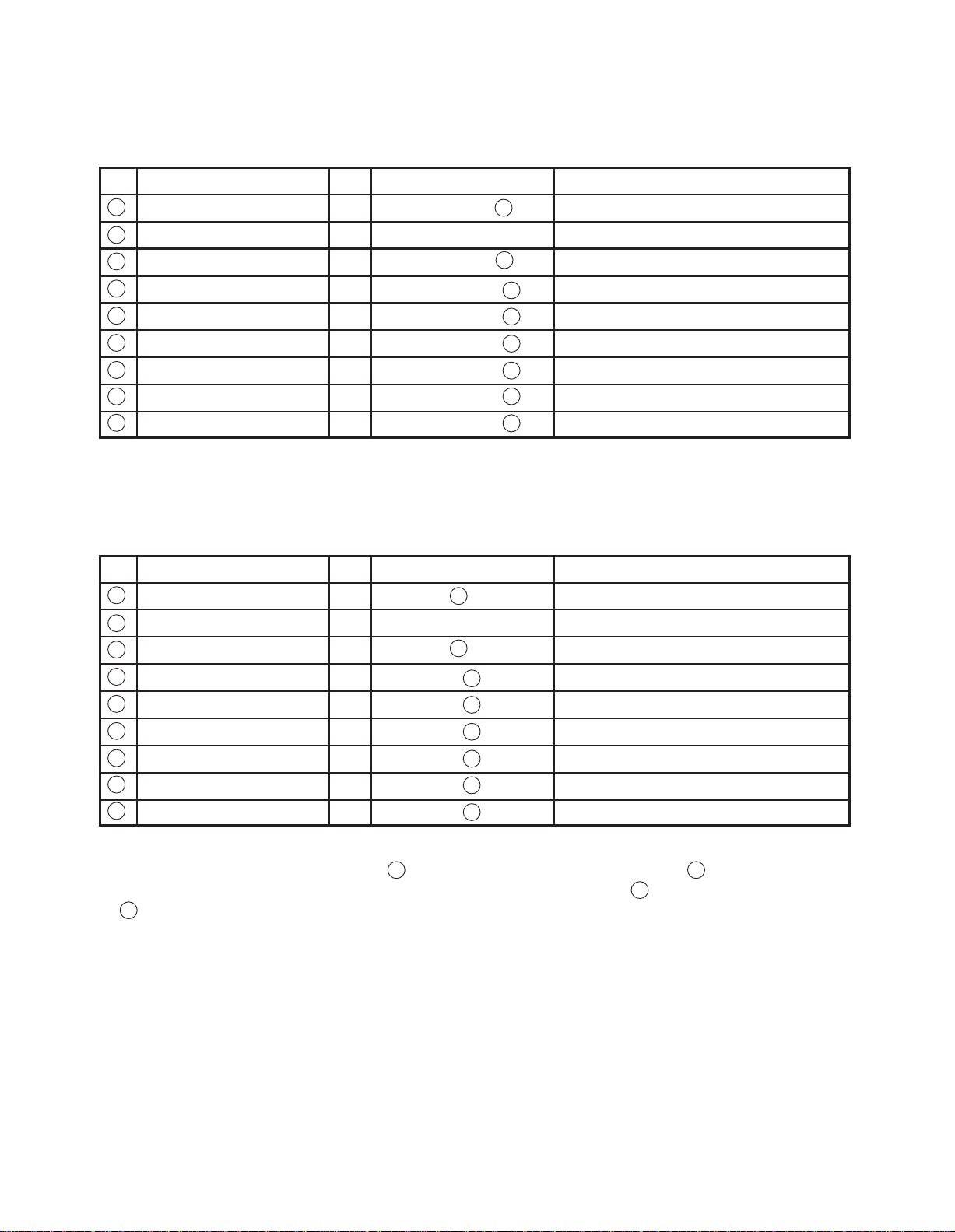
FAIRING
5 Nm (0.5 mkg, 3.6 ftlb)
Parts List
No
1
2
3
4
Parts Name Qty Location Remark
Fairing 1 Carton box “ ”
Bolt 4 Vinyl bag “ ” M6 1.0 =20 mm (0.79 in)
Washer 4 Vinyl bag “ ” D=18 mm (0.7 in) d=6 mm (0.24 in)
Nut 4 Vinyl bag “ ” M6 1.0
D
5
5
5
Set up point
1
1. Install the fairing
stopper
4
5
using the bolts 2 and nylon nuts
and washers 3.
2. Clamp the lead wire
to the shroud with shroud
A
.
3. Connect the speedometer cable
C
terlight lead
to the speedometer.
4. Connect the headlight coupler
headlight.
5. Connect the back buzzer coupler
B
and me-
D
to the
E
.
2-3
CARENAGE
Liste des pièces
N_
1
2
3
4
Nom des pièces Qté Emplacement Remarque
Carénage 1 Boîte en carton “ ”
Boulon 4 Sachet en vinyle “ ” M6 1,0 = 20 mm (0,79 in)
Rondelle 4 Sachet en vinyle “ ” D = 18 mm (0,7 in) d = 6 mm (0,24 in)
Ecrou 4 Sachet en vinyle “ ” M6 1,0
MONTERING AV STRÖMLINJEPLÅT
Detaljförteckning
Nr
Strömlinjeplåt 1 Kartong “ ”
1
Bult 4 Plastpåse “ ” M6 1,0 = 20 mm (0,79 in)
2
3
Bricka 4 Plastpåse “ ” D = 18 mm (0,7 in) d = 6 mm (0,24 in)
4
Mutter 4 Plastpåse “ ” M6 1,0
Detalj Ant Placering Anmärkning
Point de montage
1. Monter le carénage
l’aide des boulons
des rondelles
2. Fixer le fil électrique
3. Brancher le câble d’indicateur de vitesse
de témoin
C sur le compteur de vitesse.
4. Brancher le coupleur de phare
1 sur la tôle avec la butée 5 à
2 et des écrous en nylon 4 et
3 .
A .
B et le fil
D sur le phare.
5. Brancher le coupleur de l’avertisseur de marche arrière
E .
D
5
5
5
D
5
5
5
Monteringsåtgärde
1. Montera strömlinjeplåten
jets fasthållningsband
bultarna
2 , nylonmuttrarna 4 och brickorna
3.
2. Kläm fast ledningen
A.
3. Anslut hastighetsmätarkabeln
ledningen
C till hastighetsmätaren.
4. Anslut strålkastarkopplaren
ren.
5. Anslut backsummerns kopplare
1 på höljet med höl-
5 genom att använda
B och mätar-
D till strålkasta-
E.
2-3
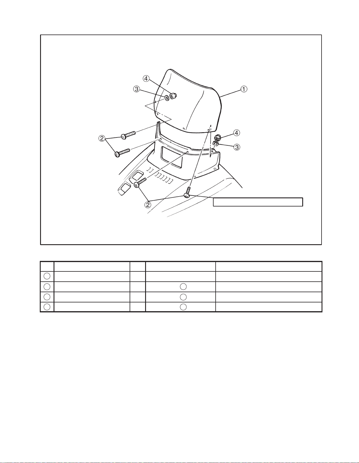
WINDSHIELD ASSEMBLY
2 Nm (0.2 mkg, 1.4 ftlb)
Parts List
No
1
2
3
4
Parts Name Qty Location Remark
Windshield 1 Place on the seat
Screw 4 Vinyl bag “ ” M5 0.8 =12.0 mm (0.47 in)
Washer 2 Vinyl bag “ ” D=18 mm (0.7 in) d=5 mm (0.2 in)
Cap nut 2 Vinyl bag “ ” M5
4
4
4
2-4

ENSEMBLE PARE-BRISE
Liste des pièces
N_
1
2
3
4
Nom des pièces Qté Emplacement Remarque
Pare-brise 1 Sur le siège
Vis 4 Sachet en vinyle “ ” M5 0,8 = 12,0 mm (0,47 in)
Rondelle 2 Sachet en vinyle “ ” D = 18 mm (0,7 in) d = 5 mm (0,2 in)
Ecrou capuchon 2 Sachet en vinyle “ ” M5
MONTERING AV VINDRUTA
Detaljförteckning
Nr
Vindruta 1 På sitsen
1
Skruv 4 Plastpåse “ ” M5 0,8 = 12,0 mm (0,47 in)
2
3
Bricka 2 Plastpåse “ ” D = 18 mm (0,7 in) d = 5 mm (0,2 in)
4
Kapselmutter 2 Plastpåse “ ” M5
Detalj Ant Placering Anmärkning
4
4
4
4
4
4
2-4
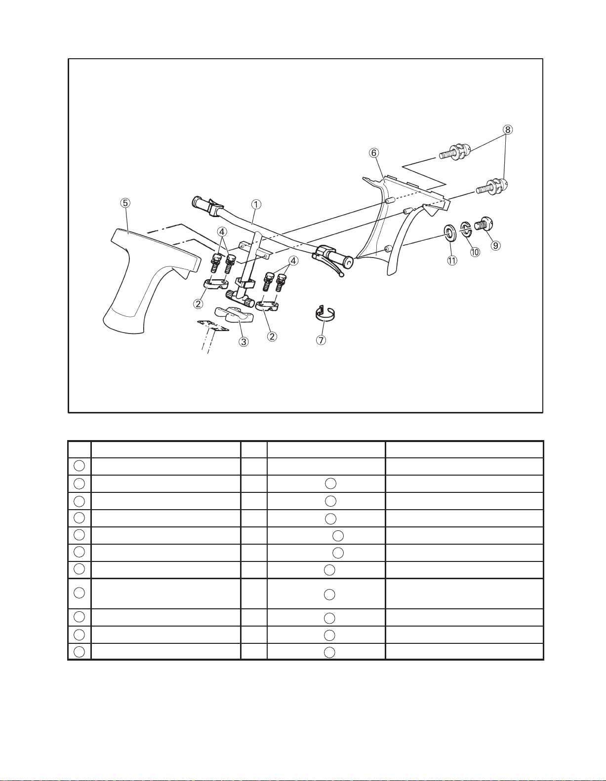
STEERING ASSEMBLY
Parts List
No
1
Handle assembly 1 Place on the Machine
Handlebar upper holder 2 Vinyl bag “ ”
2
Handlebar lower holder 1 Vinyl bag “ ”
3
Bolt with spring washer 4 Vinyl bag “ ” M8 1.25 =35 mm (1.38 in)
4
5
Upper steering pad 1 Carton box “ ”
6
Lower steering pad 1 Carton box “ ”
7
Band 1 Vinyl bag “ ”
Screw with spring washer
8
and washer
9
Screw 1 Vinyl bag “ ” M5 1.0 =8 mm (0.31 in)
Spring washer 1 Vinyl bag “ ”
10
Washer 1 Vinyl bag “ ”
11
Parts Name Qty Location Remark
A
A
A
E
E
1
2 Vinyl bag “ ” M5 1.0 =30 mm (1.18 in)
1
1
1
1
2-5
ENSEMBLE DE DIRECTION
Liste des pièces
N_
Ensemble guidon 1 Sur la machine
1
Support de guidon supérieur 2 Sachet en vinyle “ ”
2
Support de guidon inférieur 1 Sachet en vinyle “ ”
3
Boulon avec rondelle élastique 4 Sachet en vinyle “ ” M8 1,25 = 35 mm (1,38 in)
4
Rembourrage supérieur de direction 1 Boîte en carton “ ”
5
Rembourrage inférieur de direction 1 Boîte en carton “ ”
6
Collier 1 Sachet en vinyle “ ”
7
Nom des pièces Qté Emplacement Remarque
Vis avec rondelle élastique et
8
rondelle plate
Vis 1 Sachet en vinyle “ ” M5 1,0 = 8 mm (0,31 in)
9
10
Rondelle élastique 1 Sachet en vinyle “ ”
11
Rondelle 1 Sachet en vinyle “ ”
MONTERING AV STYRE
Detaljförteckning
Nr
Detalj Ant Placering Anmärkning
A
A
A
E
E
1
2 Sachet en vinyle “ ” M5 1,0 = 30 mm (1,18 in)
1
1
1
1
Styrstång 1 På maskinen
1
Övre hållare, styrstång 2 Plastpåse “ ”
2
Nedre hållare, styrstång 1 Plastpåse “ ”
3
Bult med fjäderbricka 4 Plastpåse “ ” M8 1,25 = 35 mm (1,38 in)
4
Övre styrstångskåpa 1 Kartong “ ”
5
Nedre styrstångskåpa 1 Kartong “ ”
6
Band 1 Plastpåse “ ”
7
Skruv med fjäderbricka och
8
bricka
Skruv 1 Plastpåse “ ” M5 1,0 = 8 mm (0,31 in)
9
10
Fjäderbricka 1 Plastpåse “ ”
11
Bricka 1 Plastpåse “ ”
2 Plastpåse “ ” M5 1,0 = 30 mm (1,18 in)
A
A
A
E
E
1
1
1
1
1
2-5
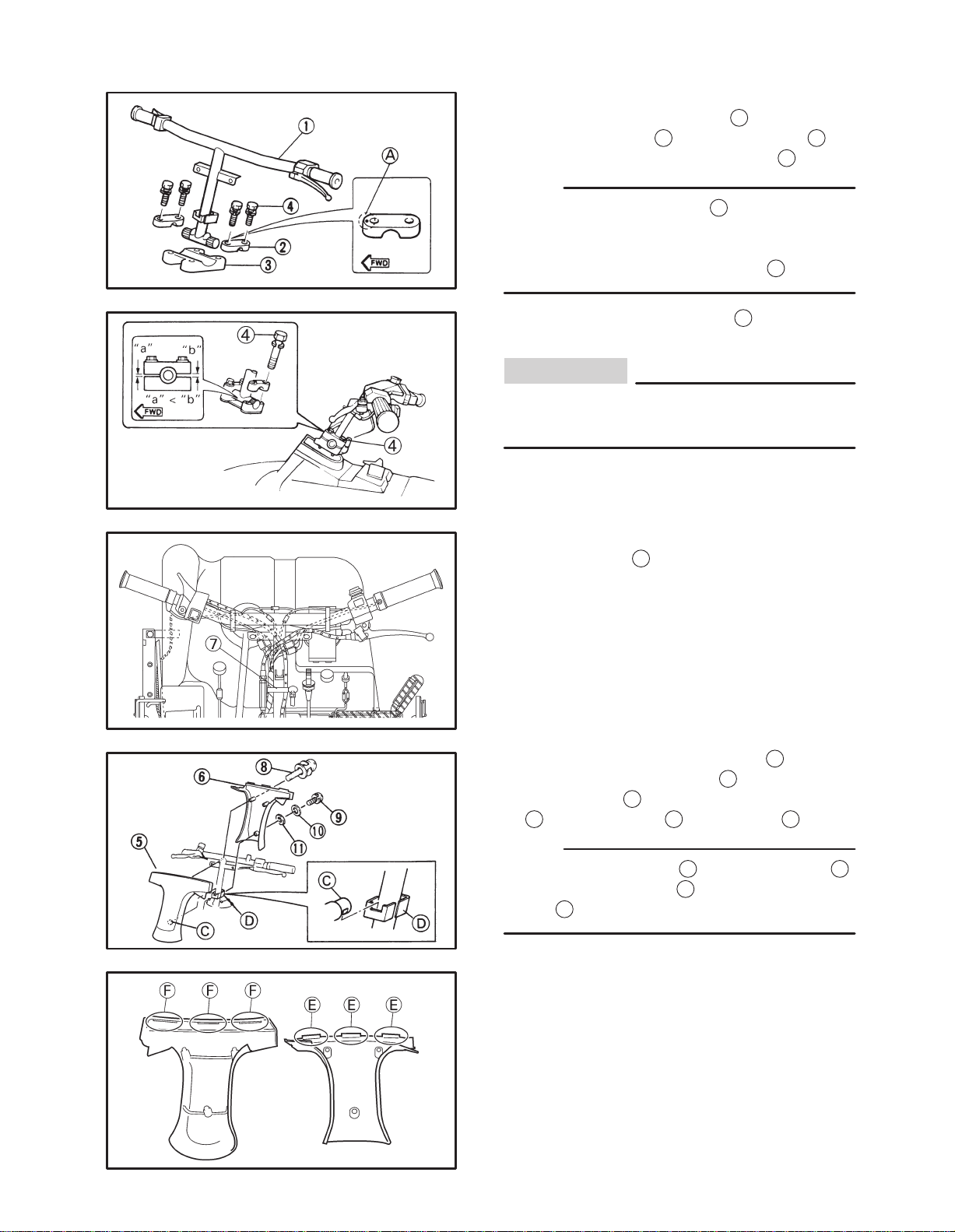
Set up point
1
1. Fit the handlebar assembly
bar upper holder
2
and lower holder 3 us-
ing the bolts with spring washers
to the handle-
4
.
NOTE:
D Temporarily tighten bolts
4
to the handlebar
holder.
D The upper handlebar holder should be
installed with the punched mark
2. Tighten the handlebar bolts
A
forward.
4
and maintain
an equal gap on each side of each holder.
CAUTION:
Be sure the small gap “a” side of the holder
faces forward.
3. Clamp the throttle cable and wire harness
with the band
7
.
4. Install the upper steering pad
handlebar using screws
6
steering pad
9
, spring washer 10 and washer 11.
to the handlebar using bolts
NOTE:
D Be sure the hooking
D Be sure the hooking
F
pad
2-6
.
C
E
5
with the
8
and the lower
to the handlebar D.
to the upper steering
Point de montage
1. Installer l’ensemble du guidon
périeur
2 du guidon et sur le support inférieur 3 à
1 sur le support su-
l’aide des boulons munis de rondelles élastiques
4 .
N.B.:
D Serrer provisoirement les boulons
4 sur le support
de guidon.
D Installer le support supérieur de guidon avec le poin-
çon
A orienté vers l’avant.
Monteringsåtgärde
1. Sätt fast styrstången
1 på dess övre hållare
2 och nedre hållare 3 med bultar med fjä-
derbrickor
OBS:
D Fäst bultarna
4.
4 på styrstångshållaren. Dra in-
te åt dem helt.
D Den övre styrstångshållaren skall monteras
med märket
A framåt.
2. Serrer les boulons du guidon
4 et les maintenir de
façon égale de chaque côté des deux supports.
ATTENTION:
Veiller à ce que le côté avec le petit écart “a” soit
orienté vers l’avant.
3. Brider le câble d’accélérateur et le faisceau de fils
avec le collier
4. Installer sur le guidon le rembourrage supérieur de
direction
rieur
6 avec le boulon 9 , la rondelle élastique
et la rondelle plate 11.
N.B.:
D Veiller à accrocher convenablement la partie
guidon
D .
D Veiller à fixer convenablement le crochet
rembourrage supérieur de direction
7 .
5 avec les vis 8 et le rembourrage infé-
10
C au
E sur le
F .
2. Drag åt styrstångsbultarna
4 . Se till att mel-
lanrummet är lika stort på båda sidorna.
VIKTIGT:
Kontrollera att den smalare skåran “a” på
styrstångshållaren vänds framåt.
3. Bunta ihop gasvajern och kabelhärvan med
bandet
4. Montera den övre styrstångskåpan
styrstången med skruvarna
den nedre stystångskåpan
med skruvarna
an
OBS:
D Haka fast kroken
D Se till att krokarna
den övre styrstångskåpan.
7.
5 på
8 och montera
6 på styrstången
9 , fjäderbrickan 10 och brick-
11
.
C i styrstången D.
E hakar fast i hålen F på
2-6
INLET PANEL ASSEMBLY
2 Nm (0.2 mkg, 1.4 ftlb)
Parts List
No
1
2
3
4
5
6
7
Parts Name Qty Location Remark
Inlet panel 1 Carton box “ ”
Grommet 1 Vinyl bag “ ”
Plate washer 1 Vinyl bag “ ”
Rivet 4 Vinyl bag “ ”
Bind screw 2 Vinyl bag “ ” M5 0.8 =16 mm (0.63 in)
Washer 4 Vinyl bag “ ” D=15 mm (0.6 in) d=5 mm (0.2 in)
U-nut 2 Vinyl bag “ ” M5
E
6
6
6
6
6
6
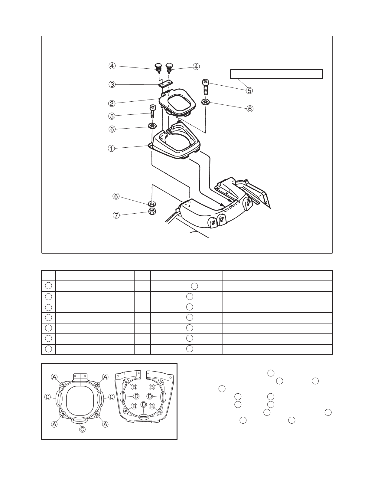
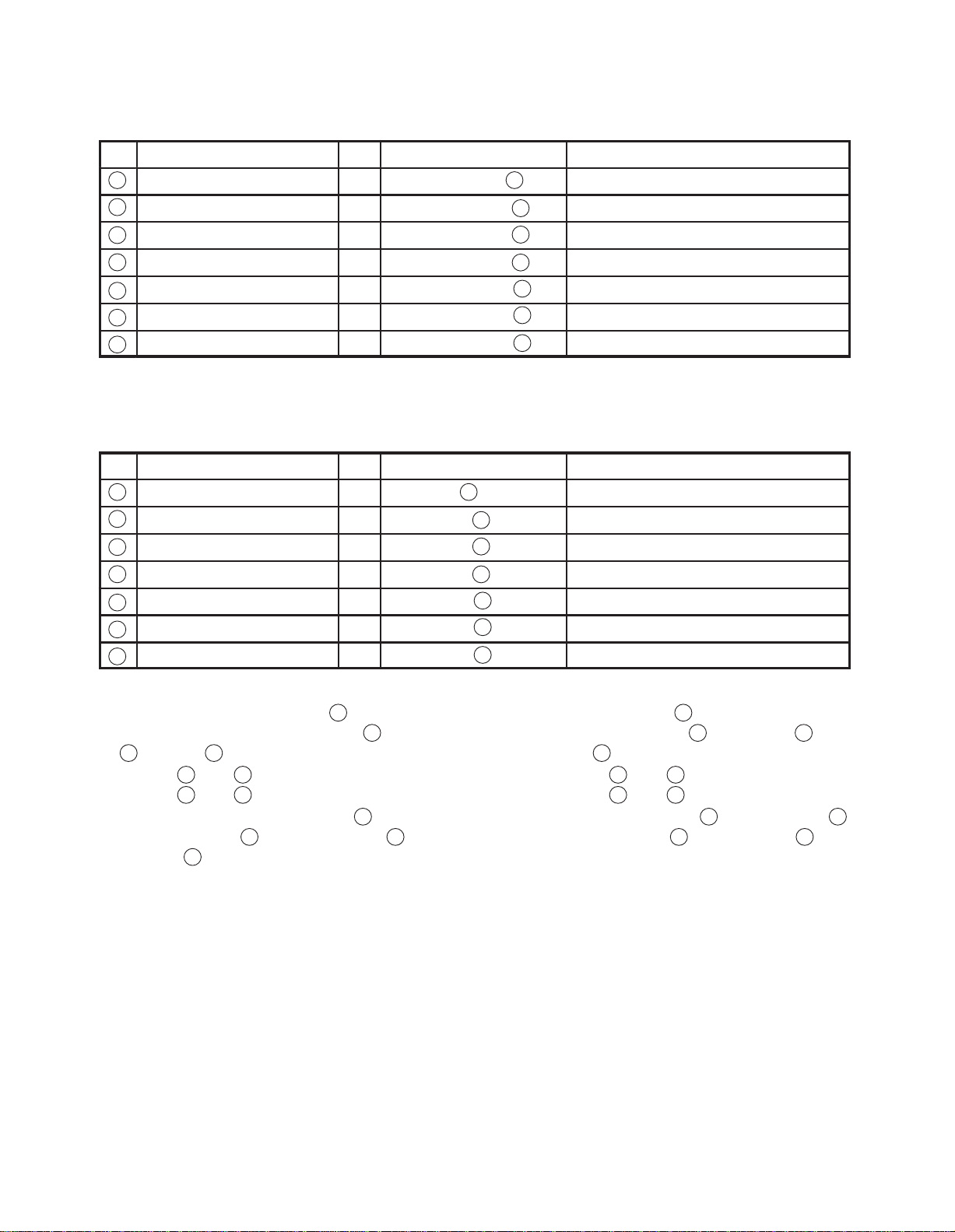
Set up point
1
1. Install the inlet panel
center cover using bolts
7
nuts
2. Install the
Install the
.
A
C
into the B.
into the D.
3. Install the grommet
into the slot on the
5
washers 6 and
2
to the inlet panel
using rivets 4 and washers 3.
1
2-7
ENSEMBLE PANNEAU D’ADMISSION
Liste des pièces
N_
1
2
3
4
5
6
7
Nom des pièces Qté Emplacement Remarque
Panneau d’admission 1 Boîte en carton “ ”
Rondelle en caoutchouc 1 Sachet en vinyle “ ”
Plaquette 1 Sachet en vinyle “ ”
Rivet 4 Sachet en vinyle “ ”
Vis de raccordement 2 Sachet en vinyle “ ” M5 0,8 = 16 mm (0,63 in)
Rondelle 4 Sachet en vinyle “ ” D = 15 mm (0,6 in) d = 5 mm (0,2 in)
Ecrou en U 2 Sachet en vinyle “ ” M5
MONTERING AV INTAGSPLÅT
Detaljförteckning
Nr
Intagsplåt 1 Kartong “ ”
1
Genomföring 1 Plastpåse “ ”
2
Platt bricka 1 Plastpåse “ ”
3
Nit 4 Plastpåse “ ”
4
Bindskruv 2 Plastpåse “ ” M5 0,8 = 16 mm (0,63 in)
5
Bricka 4 Plastpåse “ ” D = 15 mm (0,6 in) d = 5 mm (0,2 in)
6
U-mutter 2 Plastpåse “ ” M5
7
Detalj Ant Placering Anmärkning
E
6
6
6
6
6
6
E
6
6
6
6
6
6
Point de montage
1. Installer le panneau d’admission
1 dans la fente du
couvercle central à l’aide des boulons
6 et écrous 7 .
2. Installer
Installer
A dans B .
C dans D .
3. Installer la rondelle en caoutchouc
neau d’admission
rondelles
3 .
1 à l’aide des rivets 4 et des
5 , rondelles
2 sur le pan-
Monteringsåtgärde
1. Montera intagsplåten
1 i skåran på det mittre
skyddet med bultarna
muttrarna
2. Montera del
Montera del
7.
A i del B.
C i del D.
3. Montera genomföringen
med hjälp av nitarna
4 och brickorna 3.
5 , brickorna 6 och
2 i intagsplåten 1
2-7
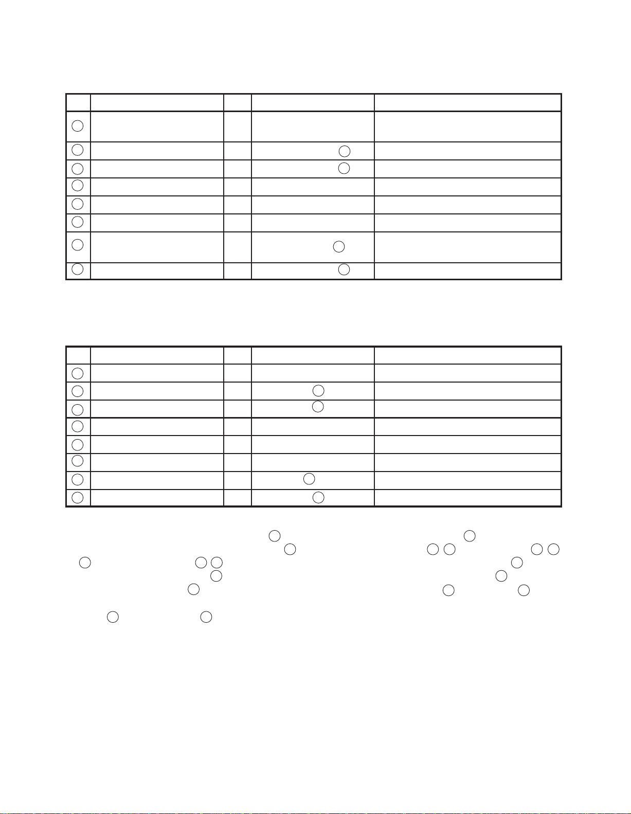
SHIFTER ASSEMBLY
7 Nm (0.7 mkg, 5.1 ftlb)
7 Nm (0.7 mkg, 5.1 ftlb)
10 Nm (1.0 mkg, 7.2 ftlb)
Parts List
No Parts Name Qty Location Remark
Shifter assembly 1 Under the seat
1
Bolt 2 Vinyl bag “ ” M6 1.0 =25 mm (0.98 in)
2
Washer 2 Vinyl bag “ ” D=11.5 mm (0.45 in) d=6.4 mm (0.25 in)
3
Bolt 1 Under the seat M6 1.0 =25 mm (0.98 in)
4
Washer 1 Under the seat D=11.5 mm (0.45 in) d=6.4 mm (0.25 in)
5
6
Nut 1 Under the seat M6
7
Shifter cover 1 Carton box “ ”
8
Rivet 4 Vinyl bag “ ”
6
6
B
6
Set up point
1. Install the shifter assembly
using the hexagon socket bolts
3 5
washers
9
to the gear case using the nut 6.
2. Fit the shifter cover
and then install the shifter rod
7
using the rivets 8.
1
to the frame
2 4
and
2-8
ENSEMBLE CHANGEMENT DE VITESSES
Liste des pièces
N_
1
2
3
4
5
6
7
8
Nom des pièces Qté Emplacement Remarque
Ensemble changement de
vitesses
Boulon 2 Sachet en vinyle “ ” M6 1,0 = 25 mm (0,98 in)
Rondelle 2 Sachet en vinyle “ ” D=11,5 mm (0,45 in) d=6,4 mm (0,25 in)
Boulon 1 Sous le siège M6 1,0 = 25 mm (0,98 in)
Rondelle 1 Sous le siège D=11,5 mm (0,45 in) d=64 mm (0,25 in)
Ecrou 1 Sous le siège M6
Couvercle du changement
de vitesses
Rivet 4 Sachet en vinyle “ ”
MONTERING AV VÄXLINGSENHET
Detaljförteckning
Nr
Växlingsenhet 1 Under sätet
1
Bult 2 Plastpåse “ ” M6 1,0 = 25 mm (0,98 in)
2
Bricka 2 Plastpåse “ ”
3
Bult 1 Under sätet M6 1,0 = 25 mm (0,98 in)
4
Bricka 1 Under sätet
5
6
Mutter 1 Under sätet M6
Växelkåpa 1 Kartong “ ”
7
Detalj Ant Placering Anmärkning
1 Sous le siège
6
6
1 Boîte en carton “ ”
B
6
6
6
B
D=11,5 mm (0,45 in) d=6,4 mm (0,25 in)
D=11,5 mm (0,45 in) d=6,4 mm (0,25 in)
Nit 4 Plastpåse “ ”
8
Point de montage
1. Installer l’ensemble changement de vitesses
le cadre à l’aide des boulons à tête hexagonale
1 sur
2
4 et des rondelles plates 3 5 , puis installer la
tige de changement de vitesses
tesses à l’aide de l’écrou
9 sur la boîte de vi-
6 .
2. Mettre en place le couvercle du changement de vitesses
7 à l’aide des rivets 8 .
6
Monteringsåtgärde
1. Montera växlingsenheten
av insexbultarna
och montera därefter växelstången
lådshuset med hjälp av muttern
2. Sätt fast växelkåpan
2-8
1 i ramen med hjälp
2 4 och brickorna 3 5
9 i växel-
6.
7 med nitarna 8.
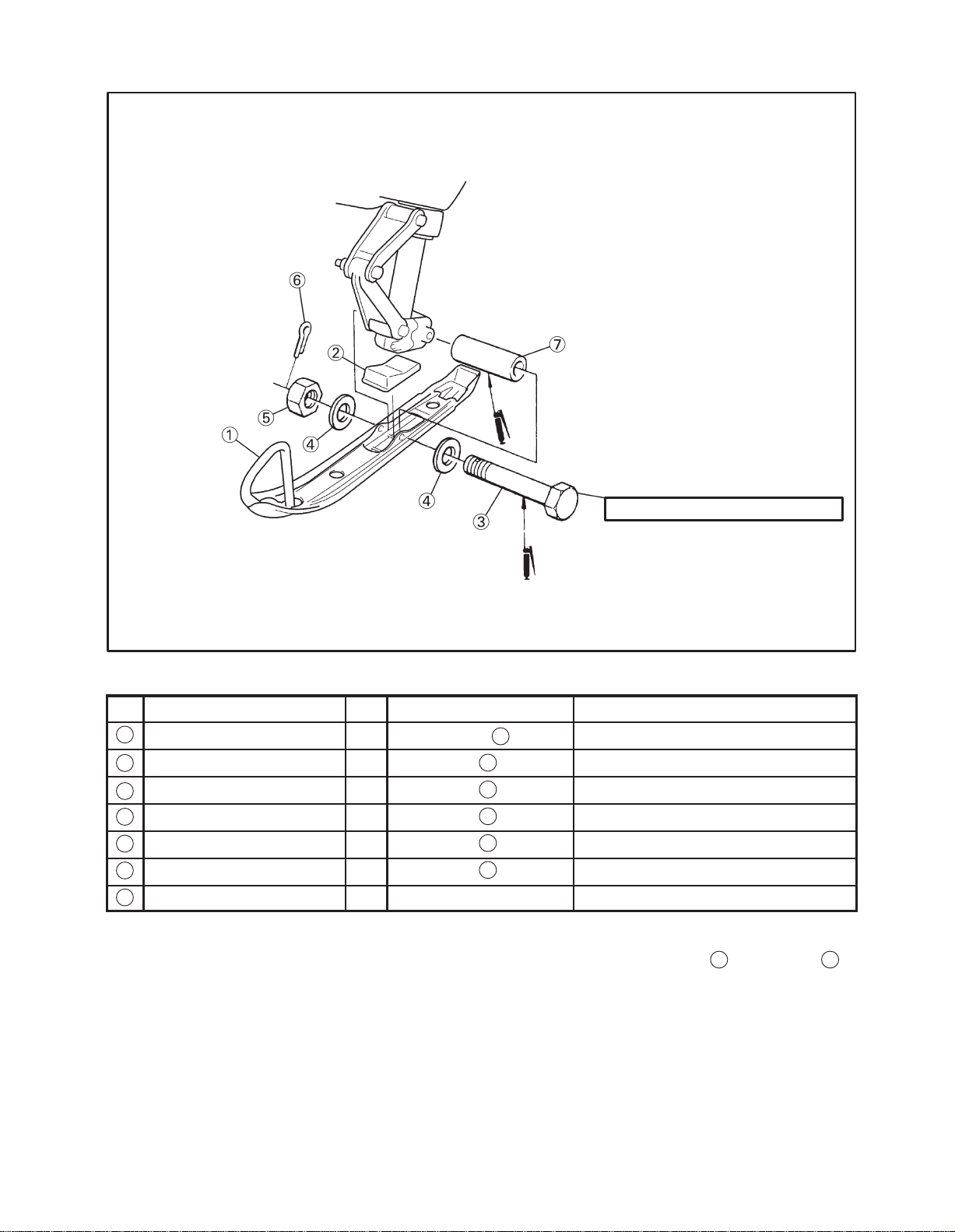
SKI ASSEMBLY
45 Nm (4.5 mkg, 32.5 ftlb)
Parts List
No
1
2
3
4
5
6
7
Parts Name Qty Location Remark
Ski assembly 2 Carton box “ ”
Stopper 2 Vinyl bag “ ”
Bolt 2 Vinyl bag “ ” M10 1.25 =102 mm (4.02 in)
Washer 4 Vinyl bag “ ” d=10 mm (0.39 in)
Nut 2 Vinyl bag “ ” M10
Cotter pin 2 Vinyl bag “ ”
B
2
2
2
2
2
Collar 2 Place in the ski bracket
Set up point
1. Apply grease to the bolt
3
and collars 7.
2-9
 Loading...