

Yamaha VK10FG User Manual
OWNER’S MANUAL
MANUEL DU PROPRIÉTAIRE
USO E MANUTENZIONE
INSTRUKTIONSBOK
OMISTAJAN KÄSIKIRJA
EIERHÅNDBOK
E
F
I
S
SF
N
E
F
S
SF
N
Read this manual carefully before operating this vehicle.
Il convient de lire attentivement ce manuel avant la première utilisation du véhicule.
I
Leggere attentamente questo manuale prima di utilizzare questo veicolo.
Läs den här instruktionsboken noga innan snöskotern används.
Lue tämä käsikirja huolellisesti ennen moottorikelkan käyttöä.
Les denne håndboken nøye før du tar kjøretøyet i bruk.
VK10FG
8KW-28199-S0

Original instructions
Notice originale
Istruzioni originali
Bruksanvisning i original
Alkuperäiset ohjeet
Opprinnelige instruksjoner
PRINTED IN JAPAN
2015.06-0.4×1 CR
PRINTED ON RECYCLED PAPER
IMPRIMÉ SUR PAPIER RECYCLÉ
STAMPATO SU CARTA RICICLATA
TRYCKT PÅ ÅTERVUNNET PAPPER
PAINETTU UUSIOPAPERILLE
TRYKKET PÅ RESIRKULERT PAPIR
Read this manual carefully
before operating this vehicle.
OWNER’S MANUAL
VK10FG
8KW-28199-S0-E0
ESU1010D
Read this manual carefully before operating this vehicle. This manual
should stay with this vehicle if it is sold.
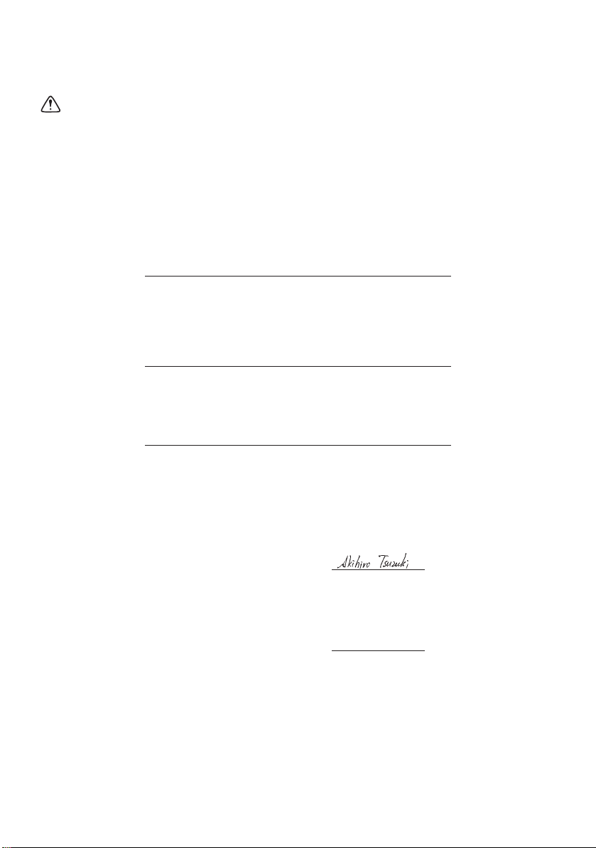
EC Declaration of Conformity
conforming to Directive 2006/42/EC
We, YAMAHA MOTOR CO., LTD. 2500 Shingai, Iwata, Japan,
declare in sole responsibility, that the product
VK10F (VK10F) (JYE8KW00∗GA000001–
to which this declaration applies, conforms to the essential health and safety
requirements of Directive 2006/42/EC
(
If applicable
and to the other relevant Directive of EEC
(
To effect correct application of the essential health and safety requirements
stated in the Directives of EEC, the following-standards and/or technical
specifications were consulted:
If applicable
(
)
(
Title and
/
or number and date of issue of the other Directives of EEC
)
Title and
/
or number and date of issue of standards and/or specifications
(
Make, model
2004/108/EC
– – – – – –
)
)
)
)
Authorized Representative
YAMAHA MOTOR EUROPE N.V.
Koolhovenlaan 101, 1119 NC Schiphol-Rijk, The Netherlands
Signature
General Manager
Engineering Div., RV Business Unit
Business Development Operations
YAMAHA MOTOR CO., LTD.
Date of Issue
Akihiro Tsuzuki
14 October, 2014
ESU10132
WARNING
Congratulations on your purchase of a
Yamaha snowmobile. This model is the result
of Yamaha’s vast experience in the production of fine sporting and touring snowmobiles. It represents the high degree of
craftsmanship and reliability that have made
Yamaha a leader in these fields.
This manual will give you an understanding of
the operation, inspection, and basic maintenance of this snowmobile. If you have any
questions concerning the operation or maintenance of your snowmobile, please consult
a Yamaha dealer.
Yamaha continually seeks advancements in
product design and quality. Therefore, while
this manual contains the most current product information available at the time of printing, there may be minor discrepancies
between your snowmobile and this manual. If
there is any question concerning this manual,
please consult a Yamaha dealer.
EWS00671
Introduction
VK10FG
OWNER’S MANUAL
©2015 by Yamaha Motor Co., Ltd.
1st Edition, April 2015
All rights reserved.
Any reprinting or unauthorized use
without the written permission of
Yama h a Mo t o r Co . , Lt d .
is expressly prohibited.
Printed in Japan.
Please read this manual carefully before
operating this snowmobile. Do not attempt to operate this snowmobile until
you have attained adequate knowledge of
its controls and operating features.
Regular inspections and careful maintenance, along with good operating techniques, will help ensure that you safely
enjoy the capabilities and reliability of this
snowmobile.
Important manual information
WARNING
NOTICE
TIP
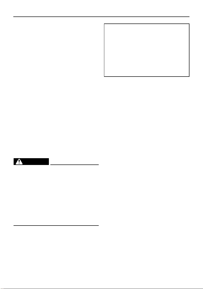
ESU10152
Particularly important information is distinguished in this manual by the following notations.
This is the safety alert symbol. It is used
to alert you to potential personal injury hazards. Obey all safety messages that follow
this symbol to avoid possible injury or death.
EWS00022
A WARNING indicates a hazardous situation which, if not avoided, could result in
death or serious injury.
ECS00012
A NOTICE indicates special precautions
that must be taken to avoid damage to the
snowmobile or other property.
A TIP provides key information to make procedures easier or clearer.

Contents
Location of the important labels...... 1
Safety information ............................. 8
Description....................................... 10
Control functions............................. 12
Main switch ................................... 12
Throttle lever ................................. 12
Throttle override system
(T.O.R.S.).................................... 12
Multi-function meter unit............... 13
High beam indicator light ............. 14
Low coolant temperature indicator
light ........................................... 14
Fuel meter and grip/thumb warmer
level indicator ............................. 15
Fuel level warning indicator ......... 16
Oil level/pressure warning
indicator .................................... 16
Coolant temperature warning
indicator .................................... 17
Self-diagnosis device .................... 17
Engine stop switch ....................... 18
Headlight beam switch
“LIGHTS” ................................... 18
Grip/thumb warmer adjusting
switch......................................... 18
Auxiliary DC jack ........................... 19
Helmet shield heater jack.............. 19
Brake lever .................................... 20
Parking brake lever ....................... 20
Shift lever ...................................... 21
Drive guard.................................... 21
V-belt holders................................ 22
Passenger grip warmer switch...... 22
Storage areas................................ 23
Tow hitch (For RUSSIA) and tow
hitch bracket (For EUROPE) ...... 25
Fuel ............................................... 25
Suspension ................................... 26
Pre-operation checks ..................... 30
Pre-operation check list................ 30
Operation ......................................... 32
Starting the engine........................ 32
Break-in ........................................ 33
Riding your snowmobile ............... 33
Maximizing drive track life ............ 37
Strap ............................................. 38
Driving........................................... 38
Stopping the engine ..................... 39
Transporting.................................. 39
Periodic maintenance and
adjustment....................................... 41
Periodic maintenance chart for the
emission control system............ 42
General maintenance and
lubrication chart ......................... 43
Tool kit .......................................... 45
Recommended equipment ........... 45
Opening and closing the shroud
and removing and installing the
right side cover .......................... 45
Checking the spark plugs ............. 46
Adjusting the throttle lever free
play ............................................ 47
Checking the throttle override
system (T.O.R.S.) ....................... 47
Checking the air filter .................... 48
High-altitude settings.................... 49
Valve clearance............................. 49
Engine oil and oil filter cartridge ... 50
Cooling system ............................. 53
V-belt ............................................ 55
Drive chain housing ...................... 58
Brake and parking brake .............. 59
Extrovert drive sprocket .............. 62
Skis and ski runners ..................... 62
Steering system ............................ 63
Drive track and slide runners ........ 64
Lubrication .................................... 67

Contents
Replacing a headlight bulb ........... 68
Adjusting the headlight beams ..... 69
Fittings and fasteners.................... 70
Battery........................................... 70
Replacing a fuse ........................... 71
Troubleshooting .............................. 74
Storage............................................. 78
Specifications .................................. 80
Consumer information.................... 82
Identification number records ....... 82
WARRANTY .................................. 82
Index ................................................. 83
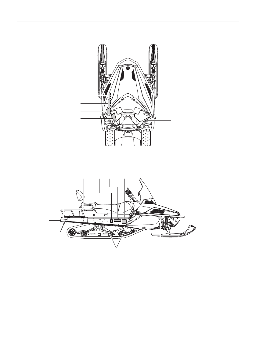
Location of the important labels
9
7,8
13
2
6
1
3
4
5
11 12
14
10
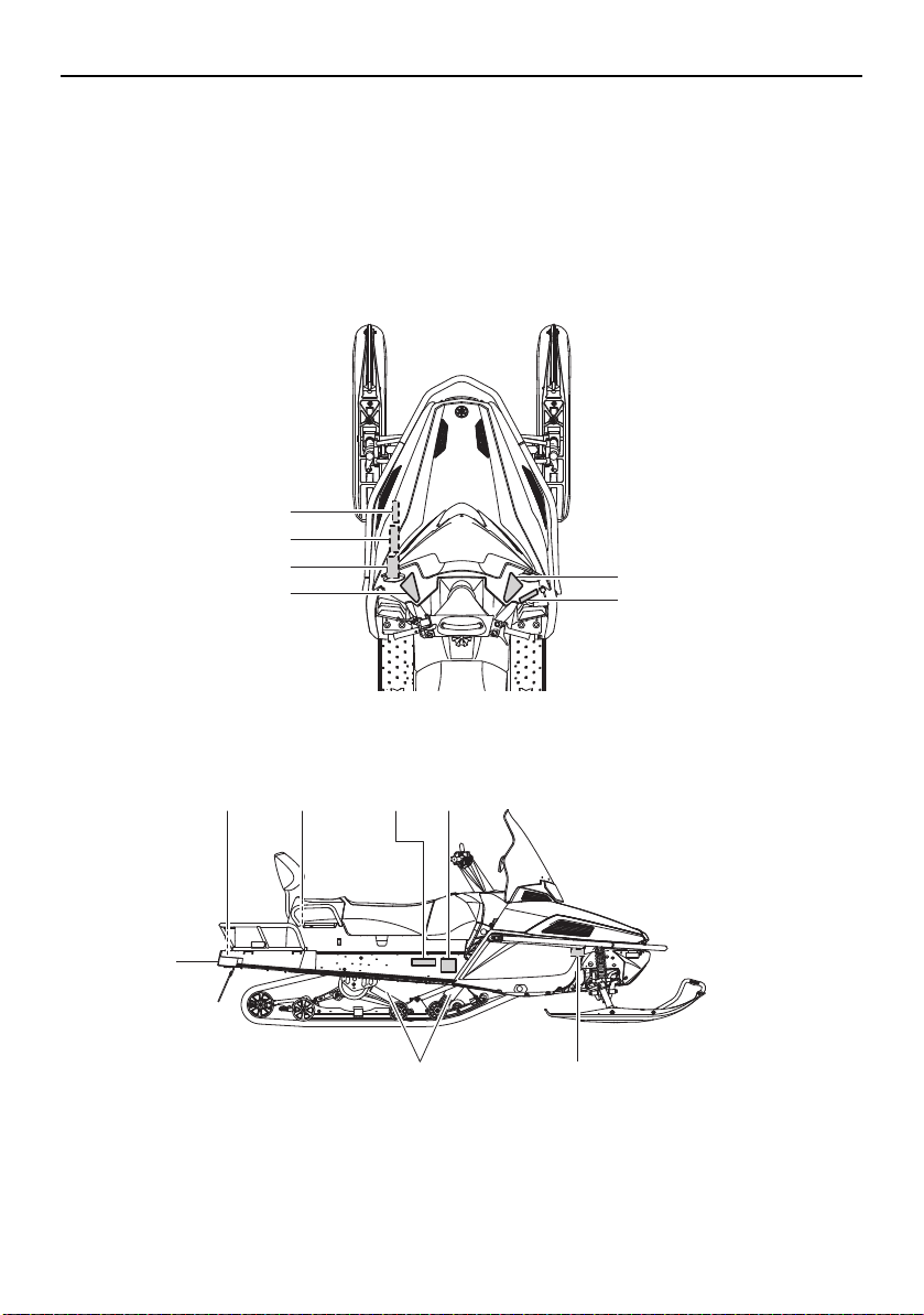
ESU1267A
Read and understand all of the labels on your vehicle. They contain important information for
safe and proper operation of your vehicle. Never remove any labels from your vehicle. If a label
becomes difficult to read or comes off, a replacement label is available from your Yamaha
dealer.
For EUROPE
1
Location of the important labels
DRIVE
1. CHAIN CASE OIL Q’TY
2. CHAIN CASE OIL TYPE
3. TRACK TENSION
* FOR MORE INFO: SEE SERVICE MANUAL FOR THIS
MODEL.
* SPECIFICATIONS SUBJECT TO CHANGE WITHOUT
NOTICE.
ENTRAÎNEMENT
1. CAPACITÉ D’HUILE DU CARTER DE CHAÎNE
2. TYPE D’HUILE DU CARTER DE CHAÎNE
3. FLÈCHE DE LA CHENILLE
* POUR PLUS DE DÉTAIL: VOIR LE MANUEL D’ATELIER
POUR CE MODÈLE.
* LES CARACTÉRISTIQUE TECHNIQUES SONT
SUSCEPTIBLES DE CHANGER SANS NOTIFICATION
PRÉALABLE.
350 cm³ (11.8 oz)
GL-3 75W or 80W
30 ~ 35 mm (1.18 ~ 1.38 in)/100 N (10 kg, 22 lb)
350 cm³
GL-3 75W or 80W
8JD-47578-00
30 ~ 35 mm/100 N (10 kg)
TUNE-UP SPECIFICATIONS
SPECIFICATIONS DE LA MISE AU POINT
TUNE-UP SPECIFICATIONS
ENGINE
1.SPARK PLUG
2.SPARK PLUG GAP
3.IDLE SPEED
SPECIFICATIONS DE LA MISE AU POINT
MOTEUR
1.TYPE DE BOUGIE
2.ECARTEMENT DES ÉLECTRODES
3.RÉGIME DE RALENTI
CR8E(NGK)
0.7 ~ 0.8 mm (0.028 ~ 0.031 in)
1300 ± 50 r/min
CR8E(NGK)
0.7 ~ 0.8 mm
1300 ± 50 r/min
8HF
8HF-1417E-00
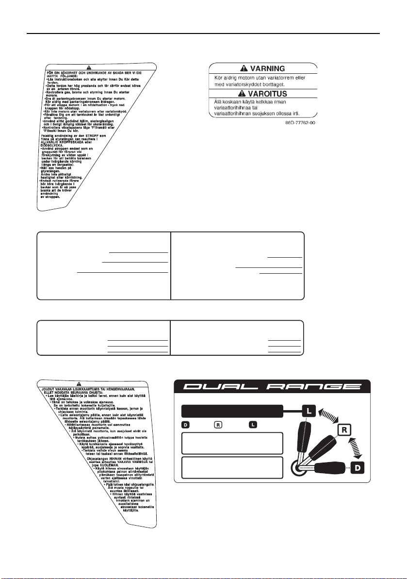
VARNING
8KW-7718A-S0
VAROITUS
8KW-7718A-F0
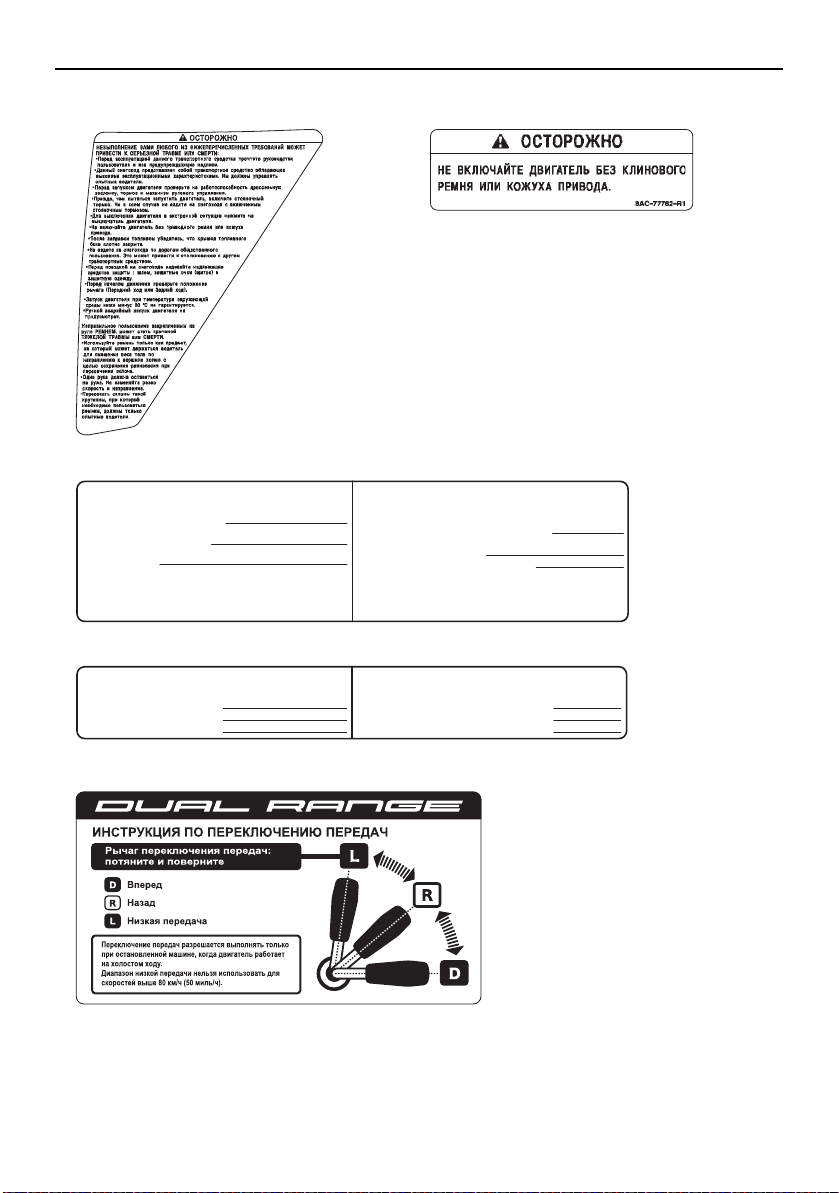
PULL
INSTRUKTION FÖR VÄXLING / VAIHTEEN VAIHTO-OHJEET
Växla bara när maskinen stoppats och motorn
går på tomgång.
Det låga läget får inte användas i hastigheter
över 80 KM/H (50 MPH).
Växelspak: Dra & vrid
Drive (framåt)
Reverse (back)
Peruutus
Låg
Pieni käyntinopeus
8KW-77763-S0
Vaihdevipu: Vedä & käännä
Ajo
•
•
Vaihda vaihdetta vain, kun kone on pysäytetty
ja moottori käy joutokäynnillä.
Pienen käyntinopeuden vaihdetta ei saa käyttää,
jos moottorikelkalla ajetaan yli 80 KM/H (50 MPH).
•
•
21
3
4
56
2
Location of the important labels
5kg {11lbs}
MAX.BELASTNING/RASKAIN TAAKKA
8FN-24897-10
20kg {44lbs}
MAX.BELASTNING/RASKAIN TAAKKA
8FM-24897-11
<
1176 N
<
147 N
8HF-2817S-00
8FA-S0
8FA-2389C-S0
8KW-2156A-00
VK10F
92.3 kW 395 kg
8AC-2817L-00
YAMAHA MOTOR CO., LTD.
2500 SHINGAI, IWATA, JAPAN
2015
4AA-22259-40
VARNING VAROITUS
8JT-77765-S0
7
910
11 12
13 14
8
3
Location of the important labels
******
*** kW *** kg
1
23
YAMAHA MOTOR CO., LTD.
2500 SHINGAI, IWATA, JAPAN
****
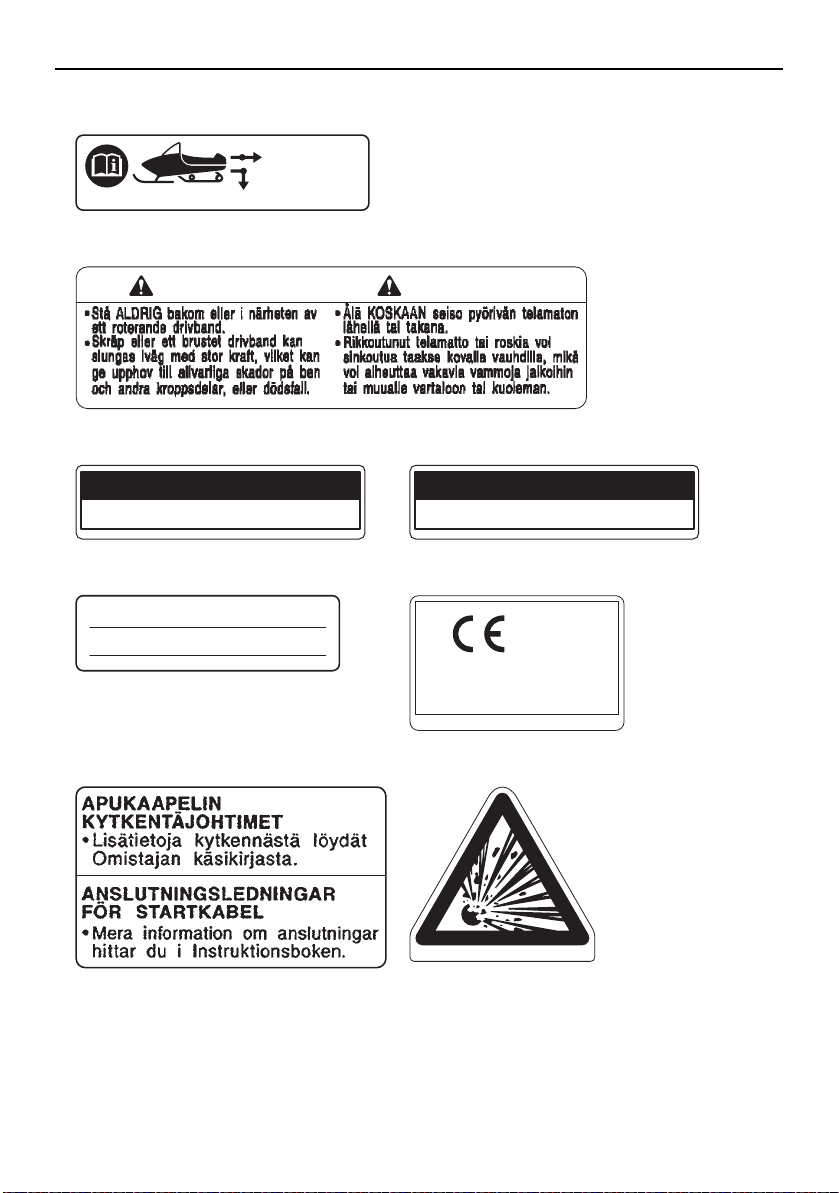
1
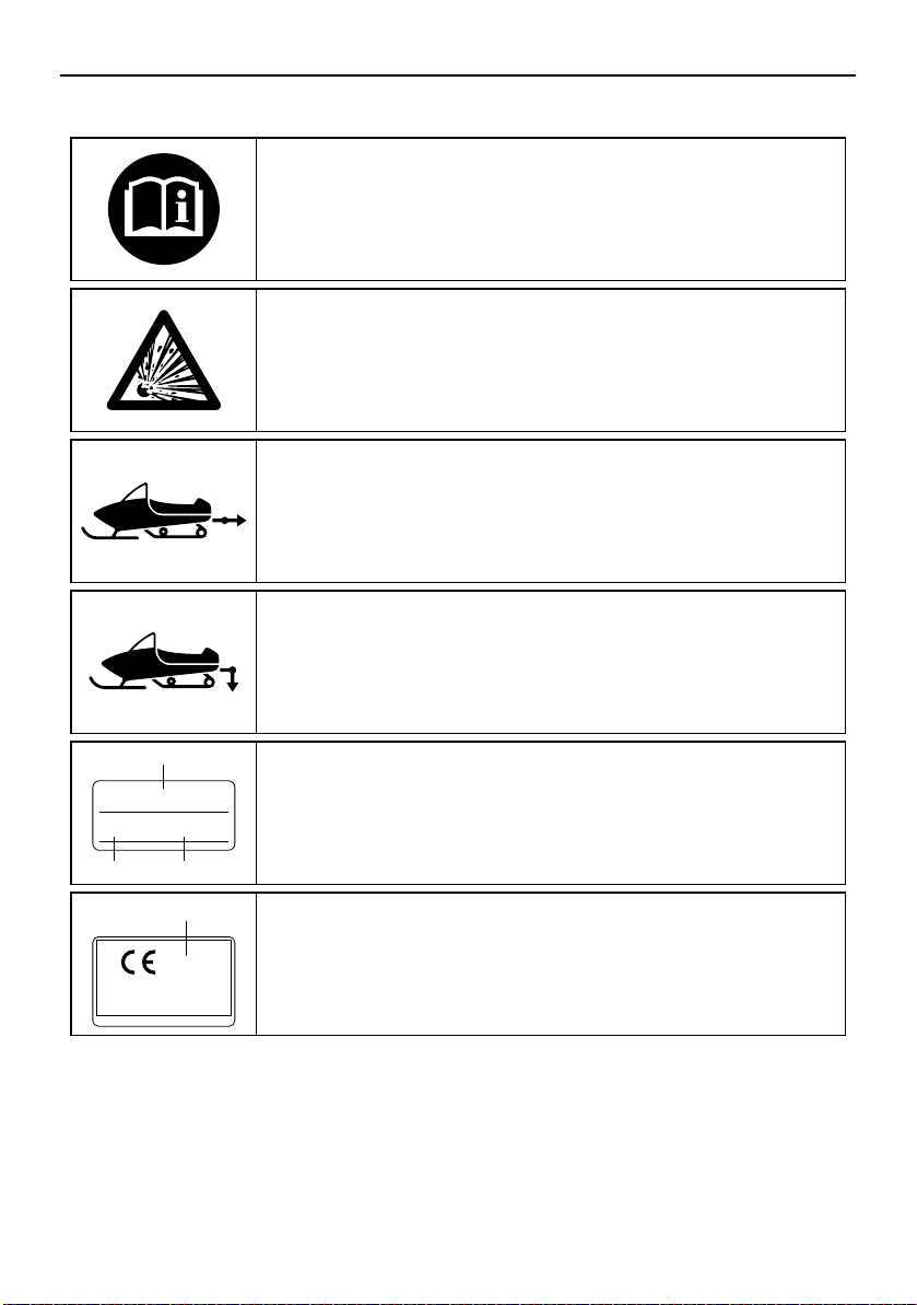
Read the Owner’s manual.
This unit contains high-pressure nitrogen gas.
Mishandling can cause an explosion. Do not incinerate,
puncture or open.
This pictogram shows the sled hitch tow weight limit
(combined weight of the sled and all cargo in the sled).
Overloading can cause loss of control.
Loss of control can result in severe injury or death.
This pictogram shows the sled hitch tongue weight limit
(weight on the sled tongue).
Overloading can cause loss of control.
Loss of control can result in severe injury or death.
1
2
3
Model Name
Max. Power
Mass In Running Order
1
Year of construction
Familiarize yourself with the following pictograms and read the explanatory text.
4
For RUSSIA
8
6,7
13
2
3
4
12
14
9 1110
1
5
Location of the important labels
5
Location of the important labels
DRIVE
1. CHAIN CASE OIL Q’TY
2. CHAIN CASE OIL TYPE
3. TRACK TENSION
* FOR MORE INFO: SEE SERVICE MANUAL FOR THIS
MODEL.
* SPECIFICATIONS SUBJECT TO CHANGE WITHOUT
NOTICE.
ENTRAÎNEMENT
1. CAPACITÉ D’HUILE DU CARTER DE CHAÎNE
2. TYPE D’HUILE DU CARTER DE CHAÎNE
3. FLÈCHE DE LA CHENILLE
* POUR PLUS DE DÉTAIL: VOIR LE MANUEL D’ATELIER
POUR CE MODÈLE.
* LES CARACTÉRISTIQUE TECHNIQUES SONT
SUSCEPTIBLES DE CHANGER SANS NOTIFICATION
PRÉALABLE.
350 cm³ (11.8 oz)
GL-3 75W or 80W
30 ~ 35 mm (1.18 ~ 1.38 in)/100 N (10 kg, 22 lb)
350 cm³
GL-3 75W or 80W
8JD-47578-00
30 ~ 35 mm/100 N (10 kg)
TUNE-UP SPECIFICATIONS
SPECIFICATIONS DE LA MISE AU POINT
TUNE-UP SPECIFICATIONS
ENGINE
1.SPARK PLUG
2.SPARK PLUG GAP
3.IDLE SPEED
SPECIFICATIONS DE LA MISE AU POINT
MOTEUR
1.TYPE DE BOUGIE
2.ECARTEMENT DES ÉLECTRODES
3.RÉGIME DE RALENTI
CR8E(NGK)
0.7 ~ 0.8 mm (0.028 ~ 0.031 in)
1300 ± 50 r/min
CR8E(NGK)
0.7 ~ 0.8 mm
1300 ± 50 r/min
8HF
8HF-1417E-00
8KW-7718A-R0
PULL
8KW-77763-R0
•
•
21
3
4
5
6
Location of the important labels
5kg {11lbs}
MAX.BELASTNING/RASKAIN TAAKKA
8FN-24897-10
20kg {44lbs}
MAX.BELASTNING/RASKAIN TAAKKA
8FM-24897-11
<
1176 N
<
147 N
8HF-2817S-00
8JT-77765-R0
8FA-S0
8FA-2389C-S0
8KW-2156A-00
VK10F
92.3 kW 395 kg
8AC-2817L-00
YAMAHA MOTOR CO., LTD.
2500 SHINGAI, IWATA, JAPAN
2015
8HN-2811S-00
4AA-22259-40
6
89
10 11
13
14
12
7
7
Safety information
ESU10204
As the vehicle’s owner, you are responsible
for the safe and proper operation of your
snowmobile. When you ride your snowmobile, you must know and use the following for
your safety. Severe injury or death may result
if you ignore any of the following.
Before you operate your snowmobile
Read the Owner’s Manual and all labels.
Become familiar with all of the operating
controls and their function. Consult a
Yamaha dealer about any control or function you do not understand.
Wear protective clothing. Wear an ap-
proved helmet, and a face shield or goggles. Also, wear a good quality snowmobile
suit, boots, and a pair of gloves or mittens
that will permit use of your thumbs and fingers for operation of the controls.
Do not operate the snowmobile after or
while drinking alcohol or taking drugs. Your
ability to operate the snowmobile is reduced by the influence of alcohol or drugs.
Prepare your snowmobile
Perform the pre-operation checks each
time you use the vehicle to make sure it is
in safe operating condition. Failure to inspect or maintain the vehicle properly in-
creases the possibility of an accident or
equipment damage. See page 30 for a list
of pre-operation checks.
Apply the parking brake before starting the
engine. Never drive the snowmobile with
the parking brake applied. This may overheat the brake disc and reduce braking
ability.
While using your snowmobile
This snowmobile was not manufactured for
use on public streets, roads, or highways.
Such use is prohibited by law, and you
could collide with another vehicle.
Be careful where you ride. There may be
obstacles hidden beneath the snow. Stay
on established trails to minimize your exposure to hazards. Ride slowly and cautiously
when you ride off of established trails. Hitting a rock or stump, or running into wires
could cause an accident and injury.
This snowmobile is not designed for use on
surfaces other than snow or ice. Use on
dirt, sand, grass, rocks, or bare pavement
may cause loss of control and may damage the snowmobile.
Always ride with other snowmobilers when
going on a ride. You may need help if you
run out of fuel, have an accident, or damage your snowmobile.
Many surfaces such as ice and hard-
packed snow require much longer stopping distances. Be alert, plan ahead and
begin decelerating early. The best braking
method on most surfaces is to release the
throttle and apply the brake gently—not
suddenly.
Avoid carbon monoxide poisoning
All engine exhaust contains carbon monoxide, a deadly gas. Breathing carbon monoxide can cause headaches, dizziness,
drowsiness, nausea, confusion, and eventu-
8

Safety information
ally death. Carbon monoxide is a colorless,
odorless, tasteless gas which may be present
even if you do not see or smell any engine exhaust. Deadly levels of carbon monoxide can
collect rapidly and you can quickly be overcome and be unable to save yourself. Also,
deadly levels of carbon monoxide can linger
for hours or days in enclosed or poorly-ventilated areas. If you experience any symptoms
of carbon monoxide poisoning, leave the
area immediately, get fresh air, and SEEK
MEDICAL TREATMENT.
Do not run the engine indoors. Even if you
try to ventilate engine exhaust with fans or
open windows and doors, carbon monoxide can rapidly reach dangerous levels.
Do not run the engine in poorly ventilated
or partially enclosed areas such as barns,
garages, or carports.
Do not run the engine outdoors where en-
gine exhaust can be drawn into a building
through openings such as windows and
doors.
Genuine Yamaha Accessories
Choosing accessories for your snowmobile is
an important decision. Genuine Yamaha Accessories, which are available only from a
Yamaha dealer, have been designed, tested,
and approved by Yamaha for use on your
snowmobile. Many companies with no connection to Yamaha manufacture parts and
accessories or offer other modifications for
Yamaha vehicles. Yamaha is not in a position
to test the products that these aftermarket
companies produce. Therefore, Yamaha can
neither endorse nor recommend the use of
accessories not sold by Yamaha or modifications not specifically recommended by
Yamaha, even if sold and installed by a
Yamaha dealer.
Maintenance and storage
When laying the snowmobile on its side for
maintenance, use a suitable stand to keep
it in a stable and level position.
Do not leave the snowmobile on its left side
for an extended period of time. Fuel may
leak out from the fuel breather hose.
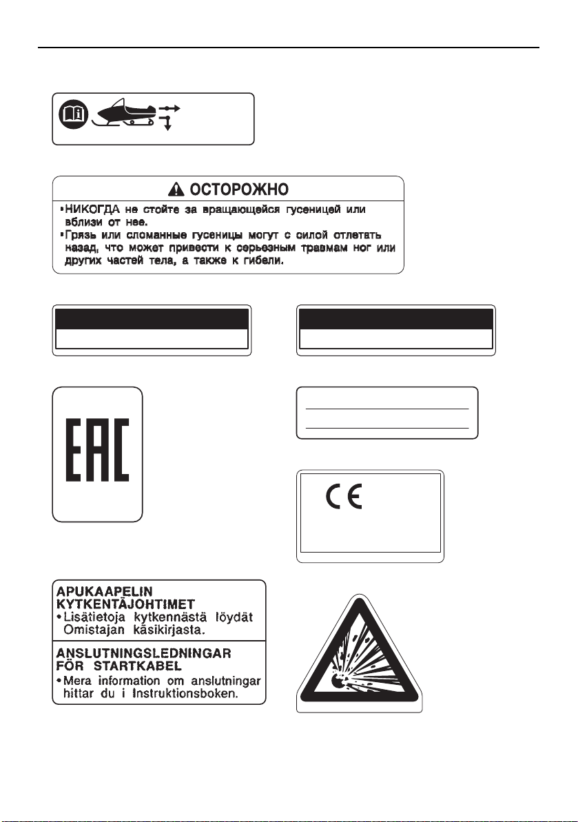
Do not allow anyone to stand behind the
snowmobile when starting, inspecting, or
adjusting the snowmobile. A broken track,
track fittings, or debris thrown by the track
could be dangerous to the operator or bystanders.
Modifications made to the snowmobile not
approved by Yamaha, or the removal of
original equipment may render your snowmobile unsafe for use, which may cause
severe personal injury. Modifications may
also make the snowmobile illegal to use.
Never store the snowmobile with fuel in the
fuel tank inside a building where ignition
sources are present such as hot water and
space heaters, an open flame, sparks,
clothes dryers, and the like. Allow the engine to cool off before storing the snowmobile in an enclosed space.
9
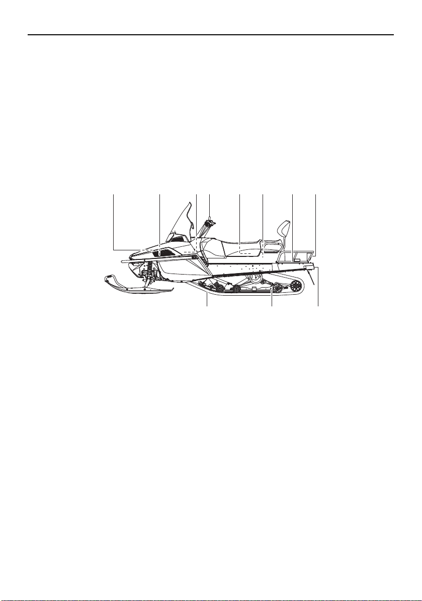
Description
1 2,3,4,5,6 78 9,10 11 12 13
14
1516
ESU10262
1. Air filter
2. Battery
3. Coolant reservoir
4. Fuse box
5. Main fuse
6. Oil filler cap
7. V-belt holder
8. Strap
9. Storage compartment
10. Tool kit
11. Passenger grip warmer switch
10
12. Rear carrier
13. Tail/brake light
14. Tow hitch bracket
15. Slide rail suspension
16. Drive track
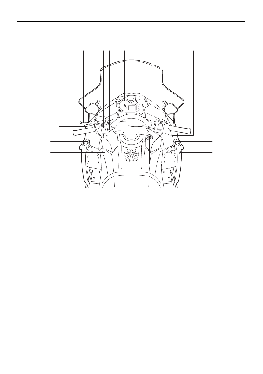
Description
TIP
12345678 9
10
11
12
10
13
1. Parking brake lever
2. Brake lever
3. Grip warmer adjusting switch
4. Helmet shield heater jack
5. Multi-function meter unit
6. Auxiliary DC jack
7. Thumb warmer adjusting switch
The snowmobile you have purchased may differ slightly from those shown in the figures of
this manual.
Design and specifications are subjected to change without notice.
8. Engine stop switch
9. Throttle lever
10. Shroud latch
11. Shift lever
12. Main switch
13. Headlight beam switch
11
Control functions
TIP
WARNING
13
2
ESU10293
Main switch
The main switch controls the ignition and
lighting systems. The various positions are
described below.
1. Off
2. On
3. Start
Off
The ignition circuit is switched off.
The key can be removed only in this position.
On
The ignition circuit is switched on.
Start
The starting circuit is switched on.
The starter motor cranks the engine.
NOTICE: Release the switch immediately
after the engine starts.
The headlights and taillight come on after the
engine is started.
ESU10313
[ECS00022]
Throttle lever
Once the engine is running cleanly, squeezing the throttle lever will increase the engine
speed and cause engagement of the drive
train. Regulate the speed of the snowmobile
by varying the throttle position. Because the
throttle is spring-loaded, the snowmobile will
decelerate, and the engine will return to idle
when it is released.
1. Throttle lever
ESU13243
Throttle override system (T.O.R.S.)
EWS00042
If the T.O.R.S. is activated, make sure that
the cause of the malfunction has been
corrected and that the engine can be operated without a problem before restarting
the engine. Continuing to operate with a
malfunction could cause loss of control or
damage.
If the throttle valves or throttle cable malfunctions during operation, the T.O.R.S. will be
activated when the throttle lever is released.
The T.O.R.S. is designed to override the fuel
injection and limit the engine speed to less
than the clutch engagement speed if the
throttle valves fail to return to the idle position
when the throttle lever is released. (See page
80 for the clutch engagement speed.)
12
Control functions
TIP
1 2
3
1 2 3 4 5 6 7
Malfunc-
tion
T. O. R. S .
will be
activated.
Throttle
lever
Throttle
valve
T.O.R.S.
Idling Riding
Released Squeezed Released
Closed Open Open
Engine
runs
properly.
Engine
runs
properly.
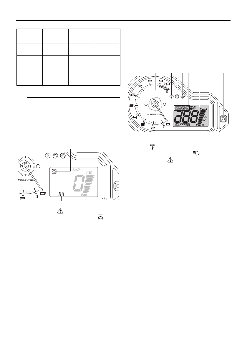
If the T.O.R.S. is activated, the warning light
and engine trouble warning indicator flash,
and the two-digit code “84” displays in the
meter display. If this occurs, have a Yamaha
dealer check the system as soon as possible.
1. Warning light “ ”
2. Engine trouble warning indicator “ ”
3. Two-digit code “84”
ESU14990
Multi-function meter unit
The multi-function meter unit is equipped
with the following:
a digital speedometer
a tachometer
an odometer
a tripmeter
warning indicators
a warning light
a low coolant temperature indicator light
a high beam indicator light
a fuel meter
a grip/thumb warmer level indicator
When the key is turned to the on position, the
tachometer needle makes one sweep, and
the low coolant temperature indicator light,
the warning light, and all segments of the meter unit display come on and go off.
1. Tachometer
2. Low coolant temperature indicator
light “ ”
3. High beam indicator light “ ”
4. Warning light “ ”
5. Warning indicators
6. Meter display
7. Select/reset button
The grip warmer level is initially displayed for
5 seconds, then the display switches to the
fuel meter.
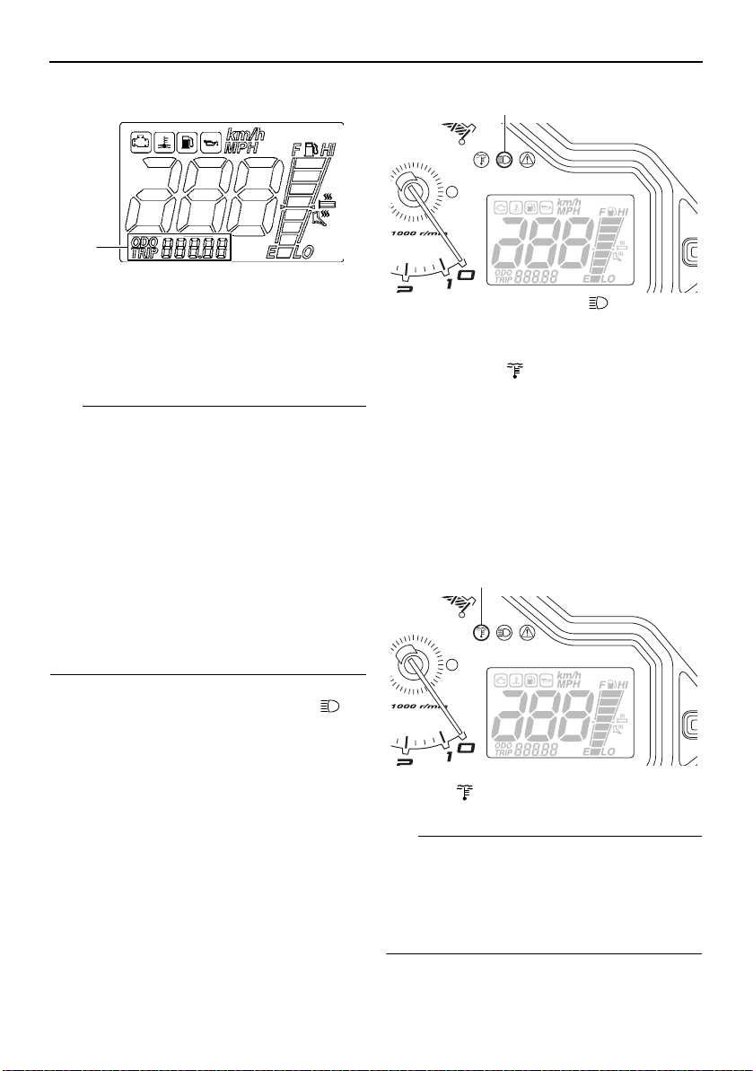
Odometer and tripmeter modes
Odometer shows the total distance that the
vehicle has run.
Tripmeter shows the distance traveled since
it last reset.
Pushing the select/reset button switches the
display between the odometer mode “ODO”
and the tripmeter mode “TRIP” in the following order:
ODO → TRIP → ODO
13
Control functions
TIP
TIP
1
1
1
1. Odometer/tripmeter
To reset the tripmeter, push the select/reset
button for at least one second while the tripmeter is displayed.
To switch the speedometer, odometer, and
tripmeter displays between kilometers and
miles, select the odometer mode “ODO”,
and then push the select/reset button for at
least 10 seconds while the snowmobile is
stopped.
Odometer resets and continues counting
when it reaches 99999 while riding. However on the 10th time, the odometer will
lock at 99999.
Tripmeter resets and continues counting
when it reaches 999.9 while riding.
ESU10412
High beam indicator light “ ”
The high beam indicator light comes on when
the high beams of the headlights are
switched on. (See page 18 for headlight
beam switch operation.)
1. High beam indicator light “ ”
ESU10474
Low coolant temperature indicator light “ ”
The low coolant temperature indicator light
comes on when the coolant temperature is
low and informs the rider that the snowmobile
should be warmed up. After the engine is
started, warm it up until the indicator light
goes off.
The snowmobile can be operated normally
after the indicator light goes off.
1. Low coolant temperature indicator
light “ ”
Drive the snowmobile at low speeds when
14
the low coolant temperature indicator light is
on. If the engine speed is too high, maximum
engine speed is reduced to protect the engine.
ESU10428
TIP
1 2
1
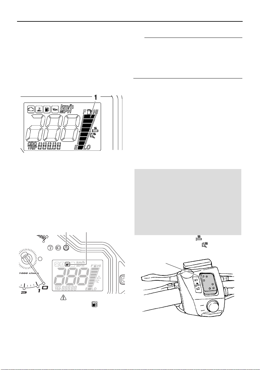
Fuel meter and grip/thumb warmer level indicator
The fuel meter and grip/thumb warmer level
indicator have eight segments which show
the amount of fuel remaining in the fuel tank,
the grip warmer level, or the thumb warmer
level.
1. Fuel meter and grip/thumb warmer level indicator
Fuel meter
The display segments of the fuel meter disappear towards “E” (Empty) as the fuel level decreases. When only one segment is left near
“E”, the fuel level warning indicator and the
warning light come on.
Control functions
The snowmobile must be stopped on a level
surface to obtain an accurate fuel meter
reading, since the reading changes according to the movement and inclination of the
snowmobile.
Grip/thumb warmer level indicator
When the grip warmer adjusting switch is
pressed, the grip warmer indicator comes on
and the display switches to the grip warmer
level.
When the thumb warmer adjusting switch is
pressed, the thumb warmer indicator comes
on and the display switches to the thumb
warmer level.
See “Grip/thumb warmer adjusting switch”
on page 18 for detailed information.
1. Warning light “ ”
2. Fuel level warning indicator “ ”
If the fuel level warning indicator and the
warning light come on, refuel as soon as possible.
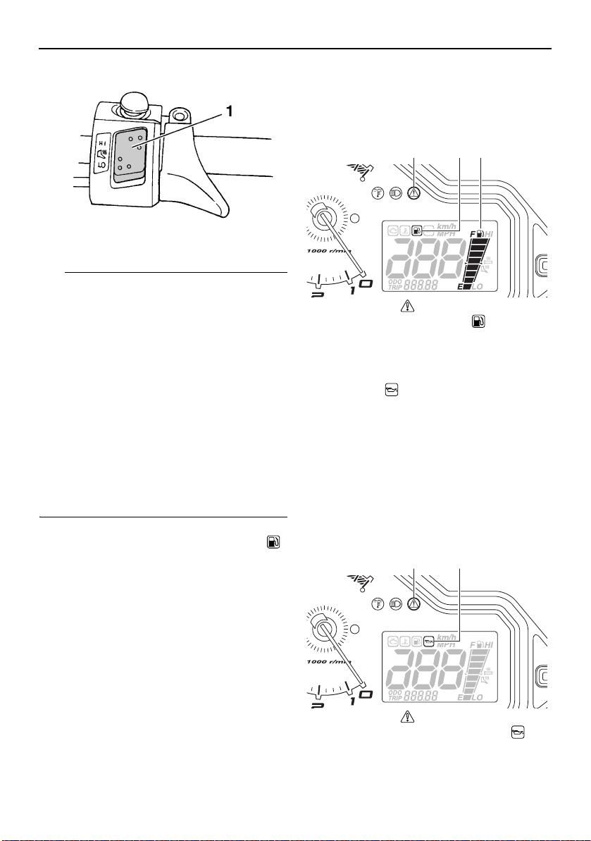
1. Grip warmer indicator “ ”
2. Thumb warmer indicator “ ”
1. Grip warmer adjusting switch
15
Control functions
TIP
1 2 3
1 2
1. Thumb warmer adjusting switch
The grip/thumb warmer level is displayed
for 5 seconds after releasing the
grip/thumb warmer adjusting switch, then
the display switches to the fuel meter.
The top segment of the grip/thumb warmer
level indicator flashes once when the
grip/thumb warmer adjustment reaches
the maximum level. The bottom segment of
the grip/thumb warmer level indicator
flashes once when the grip/thumb warmer
adjustment reaches the minimum level.
When the engine is started, the grip/thumb
warmer levels are set to the levels selected
when the engine was last stopped.
ESU10456
Fuel level warning indicator “ ”
The fuel level warning indicator and the warning light come on when the fuel level is low.
(See page 15 for details.)
The fuel level warning indicator, the warning
light, and all segments of the fuel meter start
to flash when a malfunctioning sensor, disconnected coupler, broken lead, or short circuit is detected by the self-diagnosis device
of the snowmobile to warn the rider of any of
the above problems.
If the fuel level warning indicator, the warning
light, and all segments of the fuel meter flash,
have a Yamaha dealer inspect the snowmobile as soon as possible.
1. Warning light “ ”
2. Fuel level warning indicator “ ”
3. Fuel meter
ESU13992
Oil level/pressure warning
indicator “ ”
The oil level/pressure warning indicator has
two functions. The warning indicator comes
on when the engine oil level is low and when
the engine oil pressure is low. The functions
are explained in the following sections.
Oil level warning
The warning indicator and the warning light
come on when the engine oil level is low.
1. Warning light “ ”
2. Oil level/pressure warning indicator “ ”
16
If the warning indicator and the warning light
TIP
NOTICE
1 2
1 2
come on, place the snowmobile on a level
surface and allow it to idle for one minute.
If the warning indicator and the warning light
go off, the engine oil level is sufficient, however it is getting low. Add engine oil as soon
as possible.
If the warning indicator and the warning light
do not go off, check the engine oil level in the
oil tank (see page 50 for engine oil level
checking procedures), and add engine oil if
necessary.
If the warning indicator and the warning light
still remain on, have a Yamaha dealer check
the snowmobile.
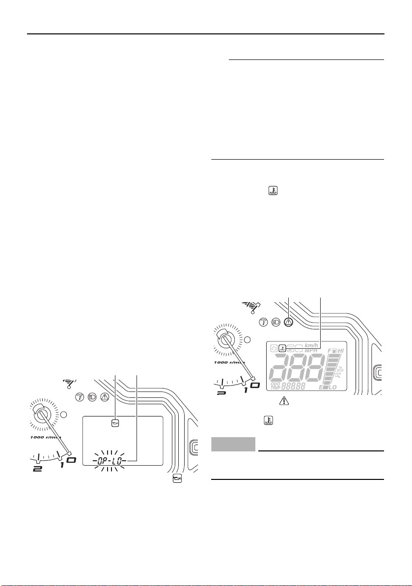
Oil pressure warning
The warning indicator comes on and “OPLO” (oil pressure low) appears in the odometer display if the engine oil pressure is low
when the engine is started. At the same time,
the engine speed is limited to less than the
clutch engagement speed until the warning
indicator goes off.
If the engine oil pressure remains low for one
minute, the engine stops. If this occurs, have
a Yamaha dealer check the snowmobile.
Control functions
If there is no engine oil in the oil passages
when the engine is started, such as after the
engine oil is changed, the warning indicator
may come on and “OP-LO” may appear in
the odometer display for a few seconds until
the oil circulates through the engine. The
snowmobile can be operated normally after
the warning indicator goes off.
ESU10514
Coolant temperature warning
indicator “ ”
If the engine overheats, the coolant temperature warning indicator and the warning light
come on. When this occurs, stop the engine
immediately and allow the engine to cool
down, and then check the coolant level in the
coolant reservoir. (See page 53 for checking
procedures.)
1. Oil level/pressure warning indicator “ ”
2. “OP-LO” (oil pressure low)
1. Warning light “ ”
2. Coolant temperature warning
indicator “ ”
ECS00042
Do not continue to operate the engine if it
is overheating.
ESU13366
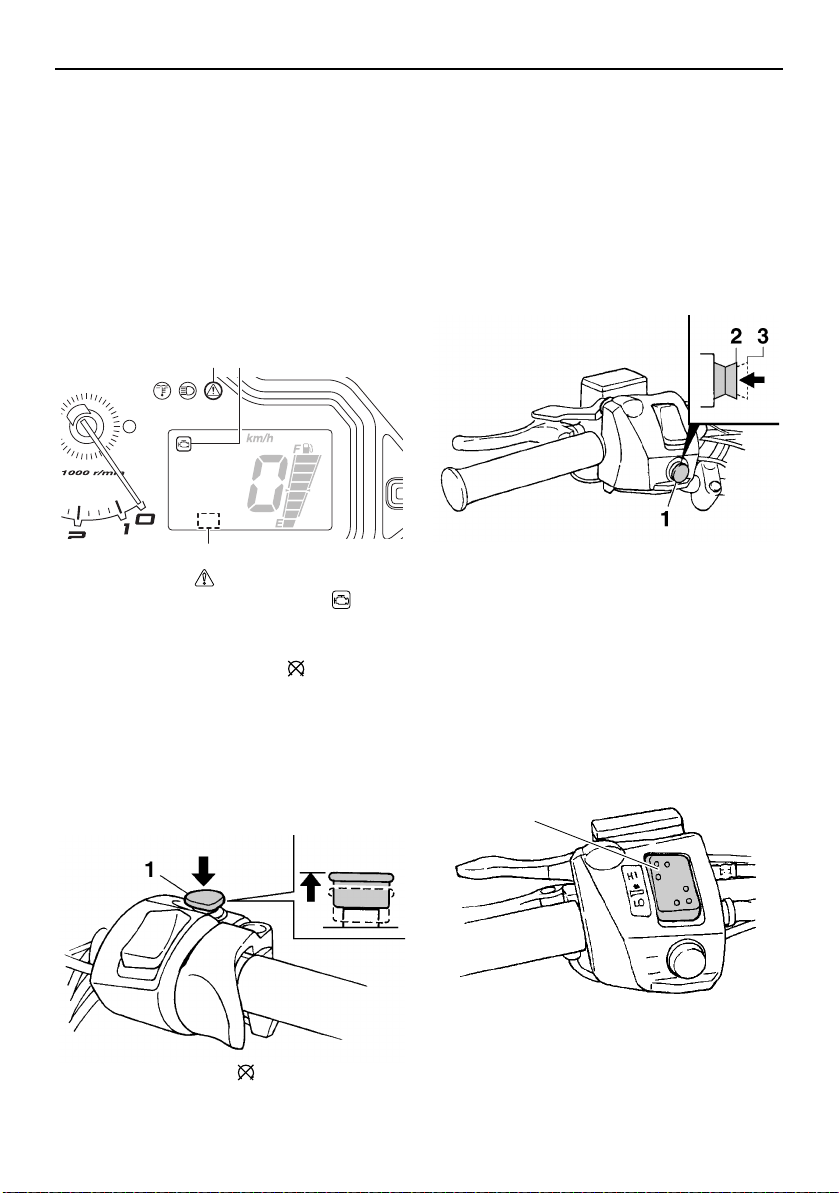
Self-diagnosis device
This model is equipped with a self-diagnosis
device for various electrical circuits.
17
Control functions
1 2
3
1
If a problem is detected in any of those circuits, the warning light and the engine trouble
warning indicator flash, and an error code
displays in the meter display. Note the error
code, and then have a Yamaha dealer inspect the snowmobile as soon as possible.
NOTICE: Do not continue to operate the
engine longer than necessary if there is an
error code to avoid possible engine damage.
[ECS00821]
1. Warning light “ ”
2. Engine trouble warning indicator “ ”
3. Error code display
ESU10532
Engine stop switch “ ”
The engine stop switch is used to stop the
engine in an emergency. Simply push the
stop switch to stop the engine. To start the
engine, pull the stop switch and proceed with
starting the engine. (See page 32 for engine
starting procedures.)
During the first few rides, practice using the
stop switch so that you can react quickly in
an emergency.
ESU10662
Headlight beam switch “LIGHTS”
Push the headlight beam switch to change
the headlight to high beam “HI” or to low
beam “LO”.
1. Headlight beam switch “LIGHTS”
2. High beam “HI”
3. Low beam “LO”
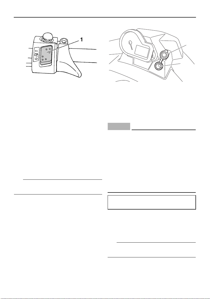
ESU12655
Grip/thumb warmer adjusting switch
The grip warmer adjusting switch and the
thumb warmer adjusting switch control the
electrically heated handlebar grips and throttle lever respectively.
1. Engine stop switch “ ”
18
1. Grip warmer adjusting switch
Control functions
TIP
NOTICE
TIP
1
2
1. Thumb warmer adjusting switch 1. Auxiliary DC jack cap
2. Auxiliary DC jack
To raise the temperature
To raise the temperature, press the respective switch to “HI”.
To lower the temperature
To lower the temperature, press the respective switch to “LO”.
See “Fuel meter and grip/thumb warmer level
indicator” on page 15 for detailed information.
ESU10697
Auxiliary DC jack
The auxiliary DC jack is located in the front
panel and can be used for accessories.
The auxiliary DC jack can only be used if the
engine is running.
3. After using the auxiliary DC jack, be sure
to remove the accessory power plug
from the jack and to close the auxiliary
DC jack cap.
ECS00123
To avoid circuit overload and a possible
fuse blowing, do not use accessories requiring more than the maximum rated
capacity for the auxiliary DC jack. (See
page 71 for the specified fuse amperage.)
Do not use an automotive cigarette
lighter or other accessory with a plug
that gets hot because the jack can be
damaged.
To use the auxiliary DC jack
1. Start the engine.
2. Open the auxiliary DC jack cap, and then
insert the accessory power plug into the
jack.
Maximum rated capacity:
DC 12 V, 2.5 A (30 W)
ESU13265
Helmet shield heater jack
The helmet shield heater jack is located on
the left side of the handlebar.
The helmet shield heater jack can only be
used if the engine is running.
To use the helmet shield heater jack
1. Start the engine.
19
Control functions
NOTICE
TIP
NOTICE
1
2
2. Open the helmet shield heater jack cap,
and then insert the power plug of the helmet shield heater into the jack.
1. Brake lever
1. Helmet shield heater jack
2. Helmet shield heater jack cap
3. After using the helmet shield heater, be
sure to remove its power plug from the
jack and to close the jack cap.
ECS00893
To avoid circuit overload and a possible
fuse blowing, do not use a helmet shield
heater requiring more than the maximum
rated capacity for the helmet shield heater
jack. (See page 71 for the specified fuse
amperage.)
Maximum rated capacity:
DC 12 V, 2.5 A (30 W)
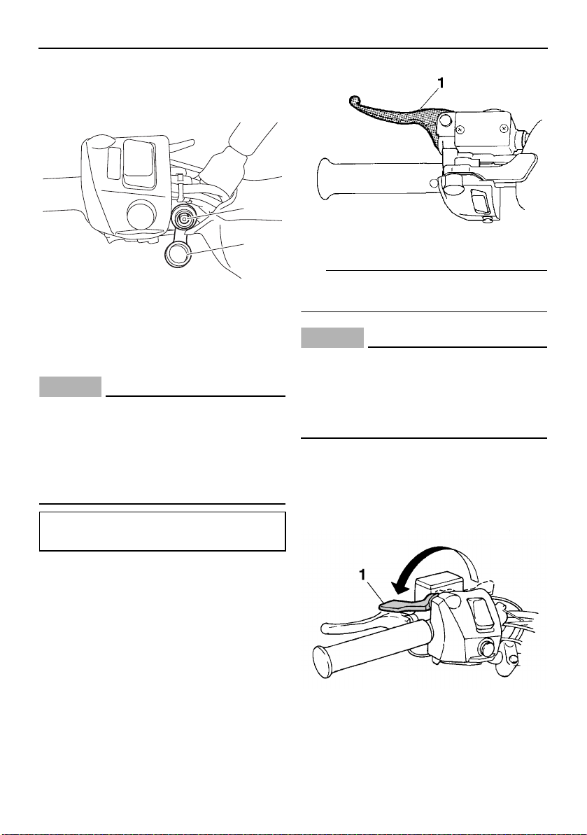
ESU10552
Brake lever
The snowmobile is stopped by braking the
entire drive system.
Squeeze the brake lever towards the handlebar grip to stop the snowmobile.
When the brake lever is squeezed, the brake
light comes on.
ECS00061
Make sure that the brake lever end does
not project out over the handlebar end.
This will help prevent brake lever damage
when the snowmobile is placed on its side
for service.
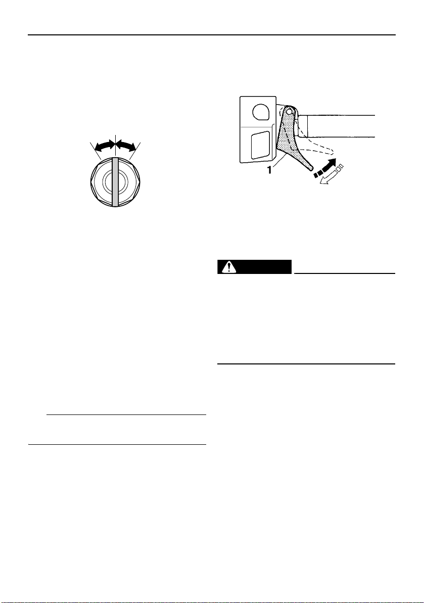
ESU10582
Parking brake lever
When parking the snowmobile or starting the
engine, apply the parking brake by moving
the parking brake lever to the left.
20
1. Parking brake lever
To release the parking brake, move the parking brake lever to the right.
ESU12563
TIP
NOTICE
WARNING
NOTICE
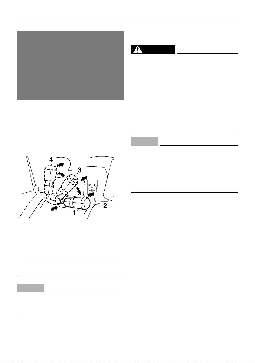
Shift lever
The shift lever is used to shift your snowmobile into drive, reverse, or low. After coming to
a complete stop, pull the shift lever out, turn
it to the desired position (“D”, “R”, or “L”), and
then release it.
Control functions
ESU15000
Drive guard
EWS00403
Coming in contact with the rotating V-
belt or clutch parts can cause severe injury or death. Never run the engine with
the drive guard removed.
Make sure that the drive guard is in-
stalled securely before operating the
snowmobile to protect against severe
injury or death from a broken V-belt or
other part should it come off the snowmobile while it is in operation.
ECS00931
Never run the engine with the V-belt re-
moved. Clutch components can be
damaged.
Be careful not to scratch the windshield
when removing or installing the drive
guard.
1. Shift lever
2. “D” Drive (forward)
3. “R” Reverse
4. “L” Low (forward)
Make sure that the shift lever is completely
shifted into position.
ECS00073
Do not use the shift lever while the snowmobile is moving, otherwise the drive train
could be damaged.
The drive guard is designed to protect the Vbelt clutch and V-belt in case parts break or
come loose.
The drive guard is located under the shroud
(see page 45 for information on how to access the drive guard).
To remove the drive guard
1. Pull out the drive guard locking pin from
the drive guard rear holder.
21
 Loading...