

Yamaha TSR-5770, HTR-5067, HTR-4067 User Manual

AV Receiver
Owner’s Manual
English
Read the supplied booklet “Safety Brochure” before using the unit.

CONTENTS
Accessories . . . . . . . . . . . . . . . . . . . . . . . . . . . . . . . . . . . . . . . . . . . . . . . . . . . . . . 4
FEATURES 5
What you can do with the unit . . . . . . . . . . . . . . . . . . . . . . . . . . . . . . . . . . . . 5
Part names and functions . . . . . . . . . . . . . . . . . . . . . . . . . . . . . . . . . . . . . . . . 7
Front panel . . . . . . . . . . . . . . . . . . . . . . . . . . . . . . . . . . . . . . . . . . . . . . . . . . . . . . . . . . . . . . . . . . . . . . . . . . . . . . . . . . . . . . . . 7
Front display (indicators) . . . . . . . . . . . . . . . . . . . . . . . . . . . . . . . . . . . . . . . . . . . . . . . . . . . . . . . . . . . . . . . . . . . . . . . . . . . 8
Rear panel . . . . . . . . . . . . . . . . . . . . . . . . . . . . . . . . . . . . . . . . . . . . . . . . . . . . . . . . . . . . . . . . . . . . . . . . . . . . . . . . . . . . . . . . . 9
Remote control . . . . . . . . . . . . . . . . . . . . . . . . . . . . . . . . . . . . . . . . . . . . . . . . . . . . . . . . . . . . . . . . . . . . . . . . . . . . . . . . . . . 10
PREPARATIONS 11
General setup procedure . . . . . . . . . . . . . . . . . . . . . . . . . . . . . . . . . . . . . . . . 11
1 Placing speakers . . . . . . . . . . . . . . . . . . . . . . . . . . . . . . . . . . . . . . . . . . . . . . 12
2 Connecting speakers . . . . . . . . . . . . . . . . . . . . . . . . . . . . . . . . . . . . . . . . . . 16
5.1-channel system . . . . . . . . . . . . . . . . . . . . . . . . . . . . . . . . . . . . . . . . . . . . . . . . . . . . . . . . . . . . . . . . . . . . . . . . . . . . . . . 16
7.1-channel system . . . . . . . . . . . . . . . . . . . . . . . . . . . . . . . . . . . . . . . . . . . . . . . . . . . . . . . . . . . . . . . . . . . . . . . . . . . . . . . 16
Connecting front speakers that support bi-amp connections . . . . . . . . . . . . . . . . . . . . . . . . . . . . . . . . . . . . . . . 17
Connecting Zone B speakers . . . . . . . . . . . . . . . . . . . . . . . . . . . . . . . . . . . . . . . . . . . . . . . . . . . . . . . . . . . . . . . . . . . . . . 17
Input/output jacks and cables . . . . . . . . . . . . . . . . . . . . . . . . . . . . . . . . . . . 18
3 Connecting a TV . . . . . . . . . . . . . . . . . . . . . . . . . . . . . . . . . . . . . . . . . . . . . . . 19
4 Connecting playback devices . . . . . . . . . . . . . . . . . . . . . . . . . . . . . . . . . . 21
Connecting video devices (such as BD/DVD players) . . . . . . . . . . . . . . . . . . . . . . . . . . . . . . . . . . . . . . . . . . . . . . . 21
Connecting audio devices (such as CD players) . . . . . . . . . . . . . . . . . . . . . . . . . . . . . . . . . . . . . . . . . . . . . . . . . . . . . 23
Connecting to the jack on the front panel . . . . . . . . . . . . . . . . . . . . . . . . . . . . . . . . . . . . . . . . . . . . . . . . . . . . . . . . . . 24
5 Connecting the FM/AM antennas . . . . . . . . . . . . . . . . . . . . . . . . . . . . . . . 24
6 Connecting to a network (wired LAN connection) . . . . . . . . . . . . . . . . 25
7 Connecting recording devices . . . . . . . . . . . . . . . . . . . . . . . . . . . . . . . . . . 26
8 Connecting the power cable . . . . . . . . . . . . . . . . . . . . . . . . . . . . . . . . . . . 26
9 Selecting an on-screen menu language . . . . . . . . . . . . . . . . . . . . . . . . . 27
10 Connecting to a network wirelessly
(HTR-5067/TSR-5770 only) . . . . . . . . . . . . . . . . . . . . . . . . . . . . . . . . . . . . . . 28
Attaching the wireless antenna . . . . . . . . . . . . . . . . . . . . . . . . . . . . . . . . . . . . . . . . . . . . . . . . . . . . . . . . . . . . . . . . . . . .28
Selecting the connection method . . . . . . . . . . . . . . . . . . . . . . . . . . . . . . . . . . . . . . . . . . . . . . . . . . . . . . . . . . . . . . . . . . 29
Connecting the unit to a wireless network . . . . . . . . . . . . . . . . . . . . . . . . . . . . . . . . . . . . . . . . . . . . . . . . . . . . . . . . .30
Connecting a mobile device to the unit directly (Wireless Direct) . . . . . . . . . . . . . . . . . . . . . . . . . . . . . . . . . . . . 36
11 Optimizing the speaker settings automatically (YPAO) . . . . . . . . . 38
Error messages . . . . . . . . . . . . . . . . . . . . . . . . . . . . . . . . . . . . . . . . . . . . . . . . . . . . . . . . . . . . . . . . . . . . . . . . . . . . . . . . . . . . 40
Warning messages . . . . . . . . . . . . . . . . . . . . . . . . . . . . . . . . . . . . . . . . . . . . . . . . . . . . . . . . . . . . . . . . . . . . . . . . . . . . . . . .41
PLAYBACK 42
Basic playback procedure . . . . . . . . . . . . . . . . . . . . . . . . . . . . . . . . . . . . . . . 42
Selecting the input source and favorite settings with one touch
(SCENE) . . . . . . . . . . . . . . . . . . . . . . . . . . . . . . . . . . . . . . . . . . . . . . . . . . . . . . . . 43
Configuring scene assignments . . . . . . . . . . . . . . . . . . . . . . . . . . . . . . . . . . . . . . . . . . . . . . . . . . . . . . . . . . . . . . . . . . . .43
Selecting the sound mode . . . . . . . . . . . . . . . . . . . . . . . . . . . . . . . . . . . . . . . 44
Enjoying stereoscopic sound fields (CINEMA DSP 3D) . . . . . . . . . . . . . . . . . . . . . . . . . . . . . . . . . . . . . . . . . . . . . . .45
Enjoying unprocessed playback . . . . . . . . . . . . . . . . . . . . . . . . . . . . . . . . . . . . . . . . . . . . . . . . . . . . . . . . . . . . . . . . . . . 47
Enjoying pure high fidelity sound (direct playback) . . . . . . . . . . . . . . . . . . . . . . . . . . . . . . . . . . . . . . . . . . . . . . . . .48
Enhancing the bass (Extra Bass) . . . . . . . . . . . . . . . . . . . . . . . . . . . . . . . . . . . . . . . . . . . . . . . . . . . . . . . . . . . . . . . . . . . .48
Enjoying compressed music with enhanced sound (Compressed Music Enhancer) . . . . . . . . . . . . . . . . . . .48
Listening to FM/AM radio . . . . . . . . . . . . . . . . . . . . . . . . . . . . . . . . . . . . . . . 49
Setting the frequency steps . . . . . . . . . . . . . . . . . . . . . . . . . . . . . . . . . . . . . . . . . . . . . . . . . . . . . . . . . . . . . . . . . . . . . . . .49
Selecting a frequency for reception . . . . . . . . . . . . . . . . . . . . . . . . . . . . . . . . . . . . . . . . . . . . . . . . . . . . . . . . . . . . . . . .49
Registering favorite radio stations (presets) . . . . . . . . . . . . . . . . . . . . . . . . . . . . . . . . . . . . . . . . . . . . . . . . . . . . . . . . 50
Radio Data System tuning . . . . . . . . . . . . . . . . . . . . . . . . . . . . . . . . . . . . . . . . . . . . . . . . . . . . . . . . . . . . . . . . . . . . . . . . .52
Playing back iPod music . . . . . . . . . . . . . . . . . . . . . . . . . . . . . . . . . . . . . . . . . 53
Connecting an iPod . . . . . . . . . . . . . . . . . . . . . . . . . . . . . . . . . . . . . . . . . . . . . . . . . . . . . . . . . . . . . . . . . . . . . . . . . . . . . . .53
Playback of iPod content . . . . . . . . . . . . . . . . . . . . . . . . . . . . . . . . . . . . . . . . . . . . . . . . . . . . . . . . . . . . . . . . . . . . . . . . . . 53
En 2

Playing back music stored on a USB storage device . . . . . . . . . . . . . . . 57
Connecting a USB storage device . . . . . . . . . . . . . . . . . . . . . . . . . . . . . . . . . . . . . . . . . . . . . . . . . . . . . . . . . . . . . . . . . . 57
Playback of USB storage device contents . . . . . . . . . . . . . . . . . . . . . . . . . . . . . . . . . . . . . . . . . . . . . . . . . . . . . . . . . . 57
Playing back music stored on media servers (PCs/NAS) . . . . . . . . . . . . 60
Media sharing setup . . . . . . . . . . . . . . . . . . . . . . . . . . . . . . . . . . . . . . . . . . . . . . . . . . . . . . . . . . . . . . . . . . . . . . . . . . . . . . 60
Playback of PC music contents . . . . . . . . . . . . . . . . . . . . . . . . . . . . . . . . . . . . . . . . . . . . . . . . . . . . . . . . . . . . . . . . . . . . 61
Listening to Internet radio . . . . . . . . . . . . . . . . . . . . . . . . . . . . . . . . . . . . . . . 64
Playback of Internet radio . . . . . . . . . . . . . . . . . . . . . . . . . . . . . . . . . . . . . . . . . . . . . . . . . . . . . . . . . . . . . . . . . . . . . . . . . 64
Registering favorite Internet radio stations (bookmarks) . . . . . . . . . . . . . . . . . . . . . . . . . . . . . . . . . . . . . . . . . . . . 66
Playing back music with AirPlay . . . . . . . . . . . . . . . . . . . . . . . . . . . . . . . . . 67
Playback of iTunes/iPod music contents . . . . . . . . . . . . . . . . . . . . . . . . . . . . . . . . . . . . . . . . . . . . . . . . . . . . . . . . . . . 67
Playing back music in multiple rooms
(HTR-5067/TSR-5770 only) . . . . . . . . . . . . . . . . . . . . . . . . . . . . . . . . . . . . . . 69
Preparing Zone B . . . . . . . . . . . . . . . . . . . . . . . . . . . . . . . . . . . . . . . . . . . . . . . . . . . . . . . . . . . . . . . . . . . . . . . . . . . . . . . . . 69
Viewing the current status . . . . . . . . . . . . . . . . . . . . . . . . . . . . . . . . . . . . . . 71
Switching information on the front display . . . . . . . . . . . . . . . . . . . . . . . . . . . . . . . . . . . . . . . . . . . . . . . . . . . . . . . . 71
Configuring playback settings for different playback sources
(Option menu) . . . . . . . . . . . . . . . . . . . . . . . . . . . . . . . . . . . . . . . . . . . . . . . . . . 72
Option menu items . . . . . . . . . . . . . . . . . . . . . . . . . . . . . . . . . . . . . . . . . . . . . . . . . . . . . . . . . . . . . . . . . . . . . . . . . . . . . . . 72
CONFIGURATIONS 76
Changing the FM/AM tuning frequency setting (TU) . . . . . . . . . . . . . . . . . . . . . . . . . . . . . . . . . . . . . . . . . . . . . . . . 95
Switching the video signal type (TV FORMAT) . . . . . . . . . . . . . . . . . . . . . . . . . . . . . . . . . . . . . . . . . . . . . . . . . . . . . .95
Restoring the default settings (INIT) . . . . . . . . . . . . . . . . . . . . . . . . . . . . . . . . . . . . . . . . . . . . . . . . . . . . . . . . . . . . . . . .95
Updating the firmware (UPDATE) . . . . . . . . . . . . . . . . . . . . . . . . . . . . . . . . . . . . . . . . . . . . . . . . . . . . . . . . . . . . . . . . . . 96
Checking the firmware version (VERSION) . . . . . . . . . . . . . . . . . . . . . . . . . . . . . . . . . . . . . . . . . . . . . . . . . . . . . . . . . .96
Updating the unit’s firmware via the network . . . . . . . . . . . . . . . . . . . . 97
APPENDIX 98
Frequently asked questions . . . . . . . . . . . . . . . . . . . . . . . . . . . . . . . . . . . . . 98
Troubleshooting . . . . . . . . . . . . . . . . . . . . . . . . . . . . . . . . . . . . . . . . . . . . . . . . 99
Power, system and remote control . . . . . . . . . . . . . . . . . . . . . . . . . . . . . . . . . . . . . . . . . . . . . . . . . . . . . . . . . . . . . . . . .99
Audio . . . . . . . . . . . . . . . . . . . . . . . . . . . . . . . . . . . . . . . . . . . . . . . . . . . . . . . . . . . . . . . . . . . . . . . . . . . . . . . . . . . . . . . . . . . .101
Video . . . . . . . . . . . . . . . . . . . . . . . . . . . . . . . . . . . . . . . . . . . . . . . . . . . . . . . . . . . . . . . . . . . . . . . . . . . . . . . . . . . . . . . . . . . .103
FM/AM radio . . . . . . . . . . . . . . . . . . . . . . . . . . . . . . . . . . . . . . . . . . . . . . . . . . . . . . . . . . . . . . . . . . . . . . . . . . . . . . . . . . . . .103
USB and network . . . . . . . . . . . . . . . . . . . . . . . . . . . . . . . . . . . . . . . . . . . . . . . . . . . . . . . . . . . . . . . . . . . . . . . . . . . . . . . . .104
Error indications on the front display . . . . . . . . . . . . . . . . . . . . . . . . . . . 106
Glossary . . . . . . . . . . . . . . . . . . . . . . . . . . . . . . . . . . . . . . . . . . . . . . . . . . . . . . 107
Audio information . . . . . . . . . . . . . . . . . . . . . . . . . . . . . . . . . . . . . . . . . . . . . . . . . . . . . . . . . . . . . . . . . . . . . . . . . . . . . . . .107
HDMI and video information . . . . . . . . . . . . . . . . . . . . . . . . . . . . . . . . . . . . . . . . . . . . . . . . . . . . . . . . . . . . . . . . . . . . . .108
Network information . . . . . . . . . . . . . . . . . . . . . . . . . . . . . . . . . . . . . . . . . . . . . . . . . . . . . . . . . . . . . . . . . . . . . . . . . . . . .108
Yamaha technologies . . . . . . . . . . . . . . . . . . . . . . . . . . . . . . . . . . . . . . . . . . . . . . . . . . . . . . . . . . . . . . . . . . . . . . . . . . . .109
Supported devices and file formats . . . . . . . . . . . . . . . . . . . . . . . . . . . . . 109
Configuring various functions (Setup menu) . . . . . . . . . . . . . . . . . . . . . . 76
Setup menu items . . . . . . . . . . . . . . . . . . . . . . . . . . . . . . . . . . . . . . . . . . . . . . . . . . . . . . . . . . . . . . . . . . . . . . . . . . . . . . . . 77
Speaker . . . . . . . . . . . . . . . . . . . . . . . . . . . . . . . . . . . . . . . . . . . . . . . . . . . . . . . . . . . . . . . . . . . . . . . . . . . . . . . . . . . . . . . . . . . 79
HDMI . . . . . . . . . . . . . . . . . . . . . . . . . . . . . . . . . . . . . . . . . . . . . . . . . . . . . . . . . . . . . . . . . . . . . . . . . . . . . . . . . . . . . . . . . . . . . 83
Sound . . . . . . . . . . . . . . . . . . . . . . . . . . . . . . . . . . . . . . . . . . . . . . . . . . . . . . . . . . . . . . . . . . . . . . . . . . . . . . . . . . . . . . . . . . . . 85
ECO . . . . . . . . . . . . . . . . . . . . . . . . . . . . . . . . . . . . . . . . . . . . . . . . . . . . . . . . . . . . . . . . . . . . . . . . . . . . . . . . . . . . . . . . . . . . . . 88
Function . . . . . . . . . . . . . . . . . . . . . . . . . . . . . . . . . . . . . . . . . . . . . . . . . . . . . . . . . . . . . . . . . . . . . . . . . . . . . . . . . . . . . . . . . . 89
Network . . . . . . . . . . . . . . . . . . . . . . . . . . . . . . . . . . . . . . . . . . . . . . . . . . . . . . . . . . . . . . . . . . . . . . . . . . . . . . . . . . . . . . . . . . 91
Language . . . . . . . . . . . . . . . . . . . . . . . . . . . . . . . . . . . . . . . . . . . . . . . . . . . . . . . . . . . . . . . . . . . . . . . . . . . . . . . . . . . . . . . . . 93
Configuring the system settings (ADVANCED SETUP menu) . . . . . . . . 94
ADVANCED SETUP menu items . . . . . . . . . . . . . . . . . . . . . . . . . . . . . . . . . . . . . . . . . . . . . . . . . . . . . . . . . . . . . . . . . . . . 94
Changing the speaker impedance setting (SP IMP.) . . . . . . . . . . . . . . . . . . . . . . . . . . . . . . . . . . . . . . . . . . . . . . . . . 94
Selecting the remote control ID (REMOTE ID) . . . . . . . . . . . . . . . . . . . . . . . . . . . . . . . . . . . . . . . . . . . . . . . . . . . . . . . 95
Video signal flow . . . . . . . . . . . . . . . . . . . . . . . . . . . . . . . . . . . . . . . . . . . . . . 110
Information on HDMI . . . . . . . . . . . . . . . . . . . . . . . . . . . . . . . . . . . . . . . . . . 111
HDMI Control . . . . . . . . . . . . . . . . . . . . . . . . . . . . . . . . . . . . . . . . . . . . . . . . . . . . . . . . . . . . . . . . . . . . . . . . . . . . . . . . . . . .111
Audio Return Channel (ARC) . . . . . . . . . . . . . . . . . . . . . . . . . . . . . . . . . . . . . . . . . . . . . . . . . . . . . . . . . . . . . . . . . . . . . .112
HDMI signal compatibility . . . . . . . . . . . . . . . . . . . . . . . . . . . . . . . . . . . . . . . . . . . . . . . . . . . . . . . . . . . . . . . . . . . . . . . .113
Reference diagram (rear panel) . . . . . . . . . . . . . . . . . . . . . . . . . . . . . . . . . 114
Trademarks . . . . . . . . . . . . . . . . . . . . . . . . . . . . . . . . . . . . . . . . . . . . . . . . . . . 115
Specifications . . . . . . . . . . . . . . . . . . . . . . . . . . . . . . . . . . . . . . . . . . . . . . . . . 116
Index . . . . . . . . . . . . . . . . . . . . . . . . . . . . . . . . . . . . . . . . . . . . . . . . . . . . . . . . . 119
En 3
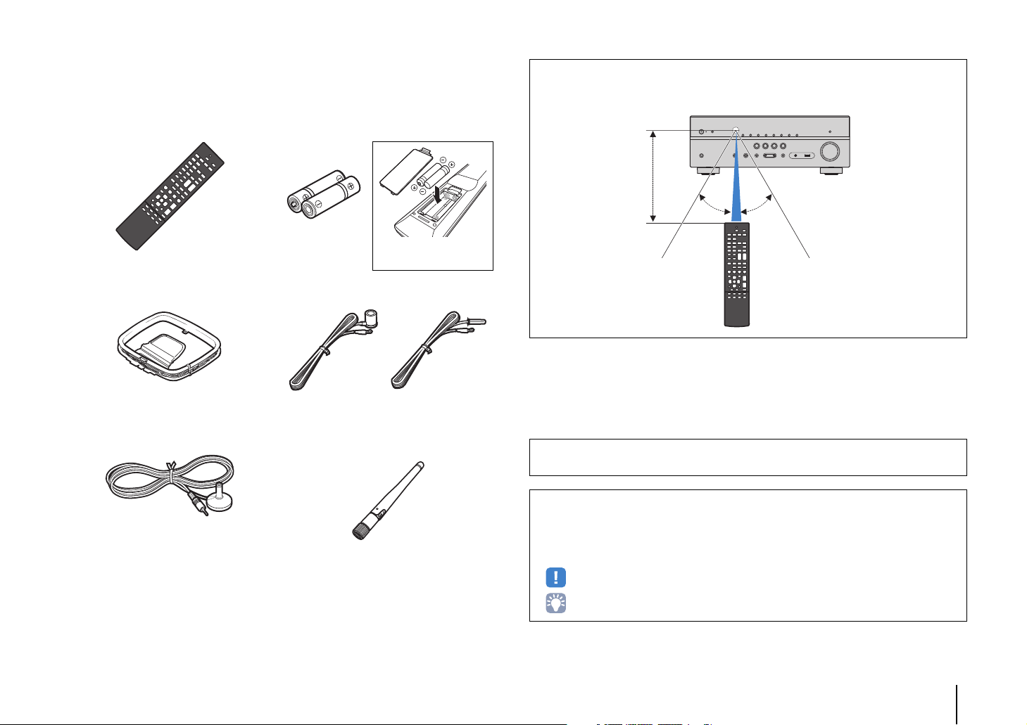
Accessories
Insert the batteries the right
way round.
30° 30°
Within 6 m (20 ft)
Check that the following accessories are supplied with the product.
Remote control Batteries (AAA, R03, UM-4) (x2)
AM antenna FM antenna
*One of the above is supplied depending on the region of
purchase.
Operating range of the remote control
• Point the remote control at the remote control sensor on the unit and remain within the operating range
shown below.
YPAO microphone Wireless antenna
(HTR-5067/TSR-5770 only)
CD-ROM (Owner’s Manual)
Easy Setup Guide
Safety Brochure
• The illustrations of the main unit used in this manual are of the HTR-5067/TSR-5770 (U.S.A. model),
unless otherwise specified.
• Some features are not available in certain regions.
• Due to product improvements, specifications and appearance are subject to change without notice.
• This manual explains operations using the supplied remote control.
• This manual describes all the “iPod” and “iPhone” as the “iPod”. “iPod” refers to both “iPod” and
“iPhone” unless otherwise specified.
• indicates precautions for use of the unit and its feature limitations.
• indicates supplementary explanations for better use.
Accessories En 4
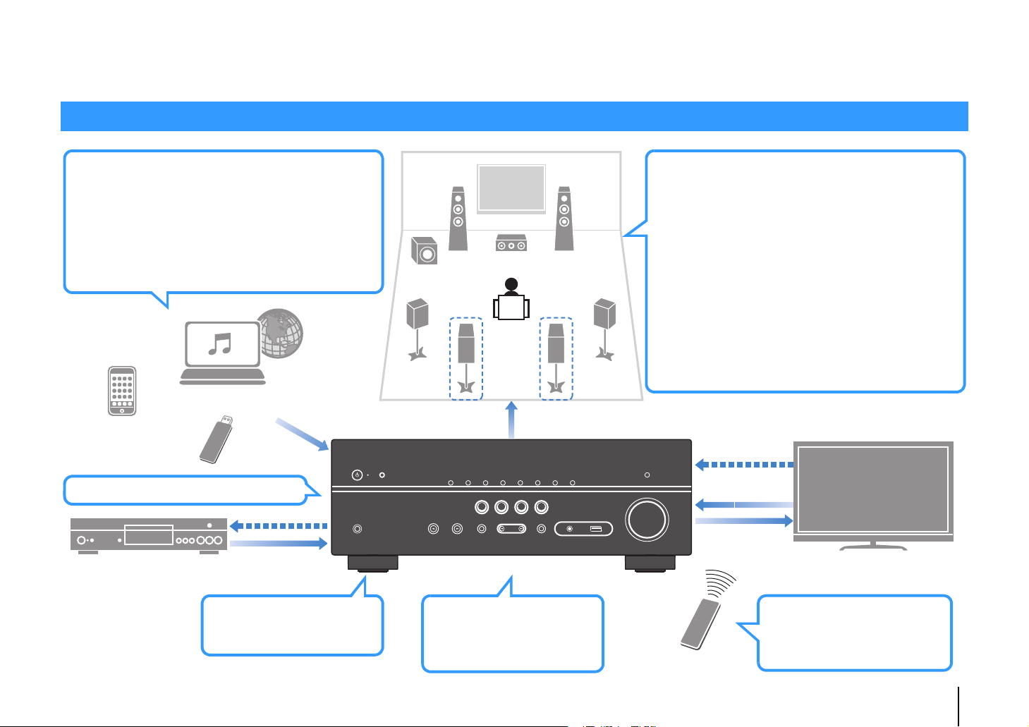
FEATURES
AV receiver (the unit)
Speakers
BD/DVD player
HDMI Control
Audio/Video
TV remote control
Audio
HDMI Control
Audio
Audio/Video
TV
Sequential operation of a TV,
AV receiver, and BD/DVD
player (HDMI Control)
. p.111
Change the input source
and favorite settings with
one touch (SCENE)
. p.43
**
* HTR-5067/TSR-5770 only
Wide variety of supported content
• iPod/iPhone
. p.53
•USB
. p.57
• Media server (PC/NAS)
. p.60
• Internet radio
. p.64
•AirPlay
. p.67
iPod/iPhone
USB device
Audio
Network contents
Supports 2- to 5.1-channel (to 7.1-channel*)
speaker system. Allows you to enjoy your favorite
acoustic spaces in various styles.
• Automatically optimizing the speaker
settings to suit your room (YPAO)
. p.38
• Reproducing stereo or multichannel
sounds with the sound fields like
actual movie theaters and concert
halls (CINEMA DSP)
. p.45
• Enjoying compressed music with
enhanced sound (Compressed Music
Enhancer)
. p.48
• Playing back music in multiple rooms
(Zone B)*
. p.69
3D and 4K Ultra HD signals supported
Wireless connection to a
network*
. p.25
* HTR-5067/TSR-5770 only
What you can do with the unit
FEATURES ➤ What you can do with the unit En 5
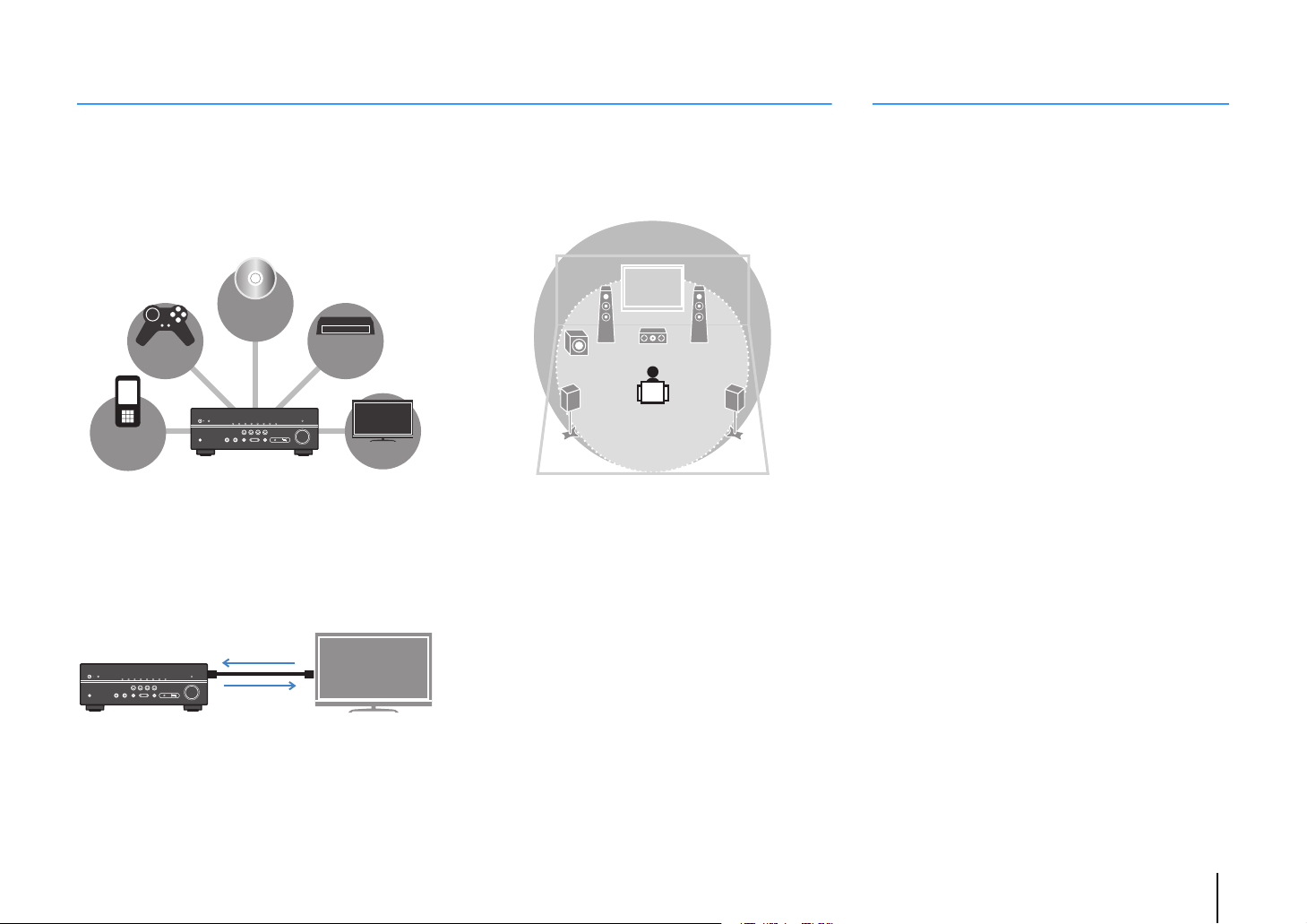
Full of useful functions!
BD/DVD
player
Game
console
Portable
audio
player
TV
Set-top box
HDMI Control
TV audio
Video from
external device
Useful tips
❑ Connecting various devices (p.21)
A number of HDMI jacks and various input/output jacks
on the unit allow you to connect video devices (such as
BD/DVD players), audio devices (such as CD players),
game consoles, portable audio player, and other
devices.
❑ Playing back TV audio in surround sound
with a single HDMI cable connection
(Audio Return Channel: ARC) (p.19)
When using an ARC -compatible TV, you only need one
HDMI cable to enable video output to the TV, audio input
from the TV, and the transmission of HDMI Control signals.
❑ Easy operation and wireless music
playback from iPhone or Android™ device
By using the application for smartphone/tablet “AV
CONTROLLER”, you can control the unit from an
iPhone, iPad, iPod touch or Android devices. Visit our
website for details.
❑ Creating 3-dimensional sound fields (p.45)
The Virtual Presence Speaker (VPS) function allows you
to create a 3-dimensional sound field in your own room
(CINEMA DSP 3D).
❑ Surround playback with 5 speakers placed
in front (p.46)
You can enjoy the surround sound even when the
surround speakers are placed in front.
❑ Enjoying pure high fidelity sound (p.48)
When the direct playback mode is enabled, the unit
plays back the selected source with the least circuitry,
which lets you to enjoy Hi-Fi sound quality.
❑ Low power consumption
The ECO mode (power saving function) reduces the
unit’s power consumption and helps to create an
eco-friendly home theater system (p.88).
The combination of video/audio input jacks does not
match an external device...
Use “Audio In” in the “Option” menu to change the
combination of video/audio input jacks so that it matches
the output jack(s) of your external device (p.22).
Video and audio are not synchronized...
Use “Lipsync” in the “Setup” menu to adjust the delay
between video and audio output (p.86).
I want to hear audio from the TV speakers...
Use “Audio Output” in the “Setup” menu to select the
output destination of signals input into the unit (p.83).
Your TV speakers may be selected as an output
destination.
I want to change the on-screen menu language...
Use “Language” in the “Setup” menu to select a
language from English, Japanese, French, German,
Spanish, Russian, Italian and Chinese (p.27).
I want to update the firmware...
Use “Network Update” (p.97) in the “Setup” menu or
“UPDATE” (p.96) in the “ADVANCED SETUP” menu to
update the unit’s firmware.
Many other settings are available that let you to
customize the unit. For details, see the following pages.
• SCENE settings (p.43)
• Sound/video settings and signal information for each
source (p.72)
• Various function settings (p.77)
• System settings (p.94)
FEATURES ➤ What you can do with the unit En 6
Part names and functions
INFO (WPS)
MEMORY
PRESET
FM AM
TUNING
CONTROL
TV
BD
DVD
NET
RADIO
INPUT
SCENE
YPAO MIC
PHONES
SILENT
CINEMA
STRAIGHT
DIRECT
AUDIO
VOLUME
AUX
TONE
PROGRAM
5V 1A
4:A2 3561 789
B
JDFG
IHCE
Front panel
1 z (power) key
Turns on/off (standby) the unit.
2 Standby indicator
Lights up when the unit is in standby mode under any of the
following conditions.
• HDMI Control is enabled (p.83)
• Standby Through is enabled (p.83)
• Network Standby is enabled (p.92)
• An iPod is being charged (p.53)
3 YPAO MIC jack
For connecting the supplied YPAO microphone (p.38).
4 Remote control sensor
Receives remote control signals (p.4).
5 INFO (WPS) key
Selects the information displayed on the front display (p.71).
(HTR-5067/TSR-5770 only)
Enters the wireless LAN connection setup (WPS button
configuration) by holding down for 3 seconds (p.30).
6 MEMORY key
Registers FM/AM radio stations as preset stations (p.50).
7 PRESET keys
Select a preset FM/AM radio station (p.51).
8 FM and AM keys
Switch between FM and AM (p.49).
9 TUNING keys
Select the radio frequency (p.49).
0 Front display
Displays information (p.8).
A DIRECT key
Enables/disables the direct playback mode (p.48).
B PHONES jack
For connecting headphones.
C INPUT keys
Select an input source.
D TONE CONTROL key
Adjusts the high-frequency range and low-frequency range
of output sounds (p.73).
E SCENE keys
Select the registered input source and sound program with
one touch. Also, turns on the unit when it is in standby mode
(p.43).
F PROGRAM keys
Select a sound program or a surround decoder (p.44).
G STRAIGHT key
Enables/disables the straight decode mode (p.47).
H AUX j ack
For connecting devices, such as portable audio players
(p.24).
I USB jack
For connecting a USB storage device (p.57) or an iPod
(p.53).
J VOLUME knob
Adjusts the volume.
FEATURES ➤ Part names and functions En 7
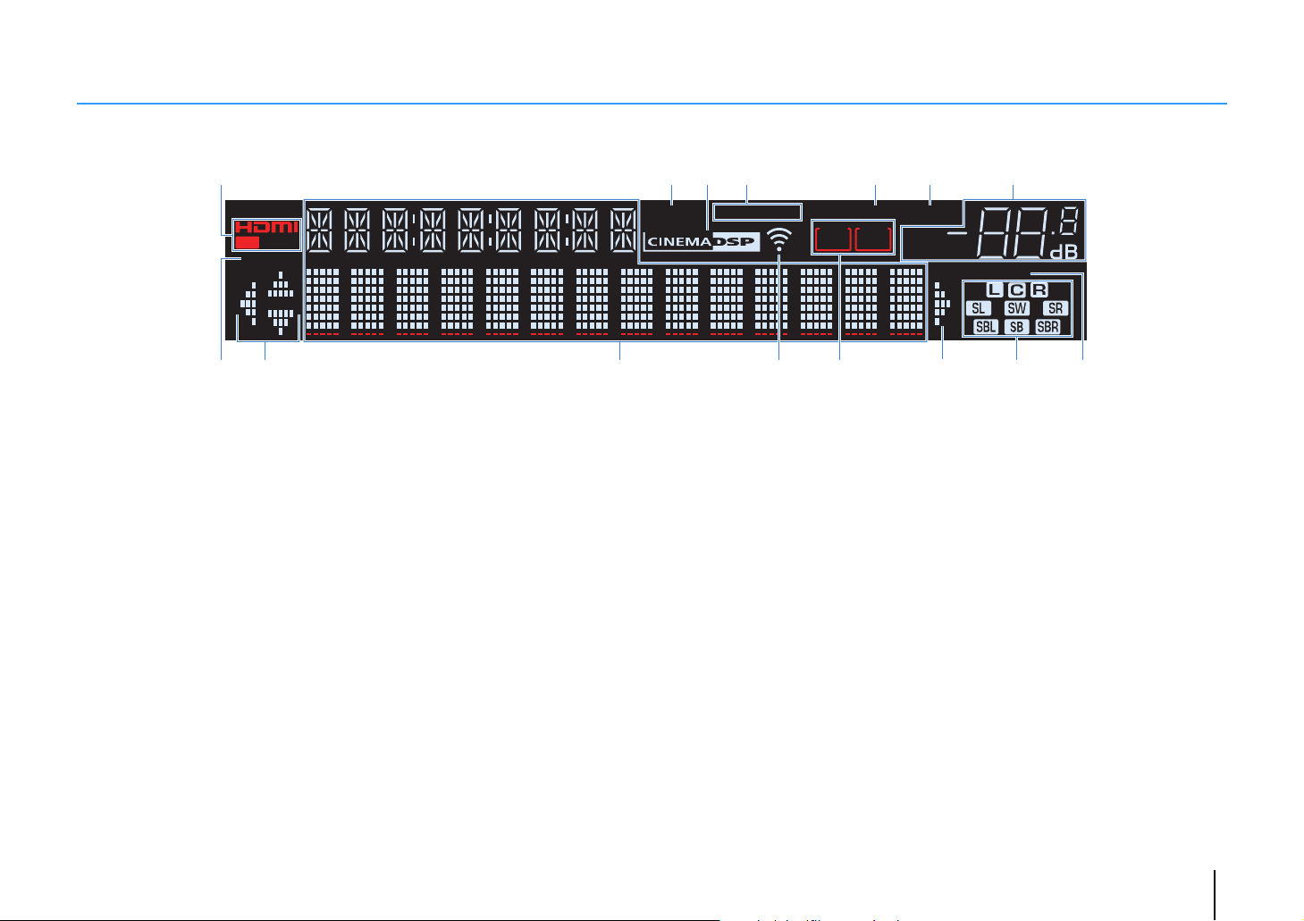
Front display (indicators)
CHARGE
1 2
OUT
ECO
SP IMP.••8 MIN
23 6541 7
SLEEP
ENHANCER
STEREO
TUNED
PARTY
ZONEAZONE
23
B
MUTE
VOL.
ADAPTIVE DRC
VIRTUAL
9 908 CDB
1 HDMI
Lights up when HDMI signals are being input or output.
OUT
Lights up when HDMI signals are being output.
2 ENHANCER
Lights up when Compressed Music Enhancer (p.48) is
working.
3 CINEMA DSP
Lights up when CINEMA DSP (p.45) or CINEMA DSP 3D
(p.45) is working.
4 STEREO
Lights up when the unit is receiving a stereo FM radio signal.
TUNED
Lights up when the unit is receiving an FM/AM radio station
signal.
5 SLEEP
Lights up when the sleep timer is on.
A
6 MUTE
Blinks when audio is muted.
7 Volume indicator
Indicates the current volume.
8 ECO
Lights up when the eco mode (p.88) is enabled.
9 Cursor indicators
Indicate the remote control cursor keys currently operational.
0 Information display
Displays the current status (such as input name and sound
mode name). You can switch the information by pressing
INFO (p.71).
A Signal strength indicator
(HTR-5067/TSR-5770 only)
Indicates the strength of the wireless signal (p.28).
B ZONE indicators (HTR-5067/TSR-5770 only)
Indicate the zone to which the sound is output (p.70).
C Speaker indicators
Indicate speaker terminals from which signals are output.
A Front speaker (L)
S Front speaker (R)
D Center speaker
F Surround speaker (L)
G Surround speaker (R)
H Surround back speaker (L)*
J Surround back speaker (R)*
K Surround back speaker*
L Subwoofer
* HTR-5067/TSR-5770 only
D ADAPTIVE DRC
Lights up when Adaptive DRC (p.73) is working.
FEATURES ➤ Part names and functions En 8
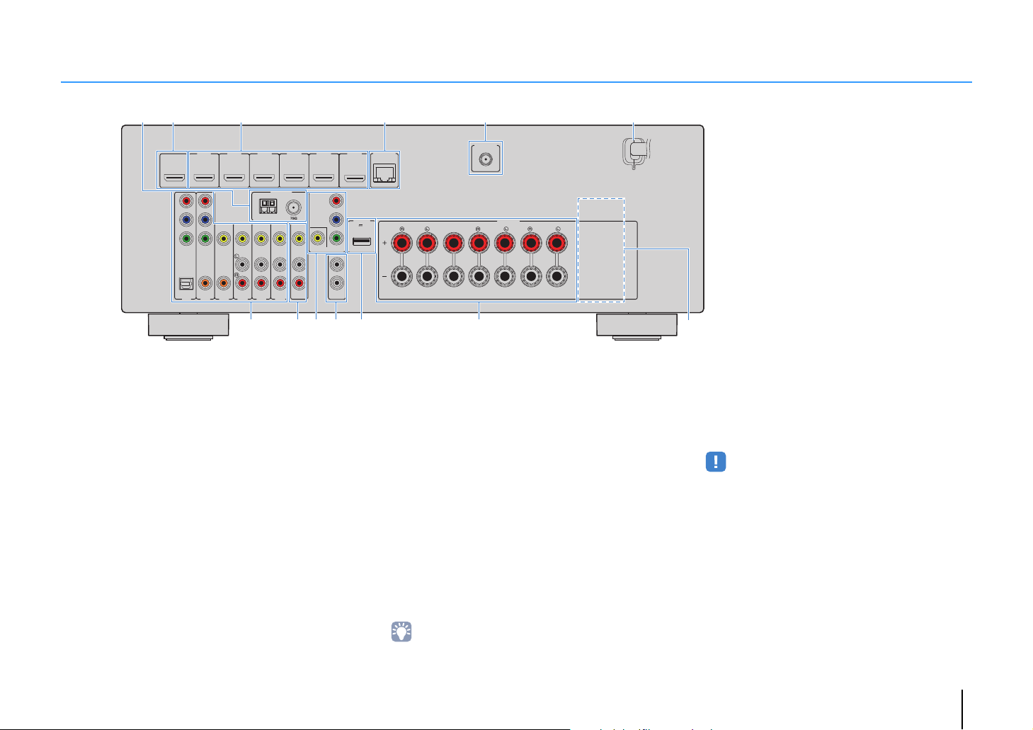
Rear panel
FRONT CENTER SURROUND
SINGLE
SURROUND BACK/BI AMP
/ZONE B
AV 1
AV 2
AV 3
AV 5
AV 6
OPTICAL COAXIAL COAXIAL
(
TV
)
COMPONENT
VIDEO
COMPONENT
VIDEO
P
B
Y
VIDEO
AV
MONITOR OUT
OUT
AV 4
P
R
P
B
Y
P
R
NETWORK
FM
ANTENNA
AM
SPEAKERS
HDMI 1
(
BD/DVD
)
HDMI 2
HDMI 3
HDMI 4
HDMI
OUT
ARC
(
RADIO
)
SUBWOOFER
PRE OUT
2
1
HDMI 5
DC OUT
5V 0.5A
HDMI 6
(
NET
)
WIRELESS
0 AB8
21
3 654
7
C
9
* The area around the video/audio output jacks is
marked in white on the actual product to prevent
improper connections.
(HTR-5067/TSR-5770 U.S.A. model)
1 ANTENNA jacks
For connecting to FM and AM antennas (p.24).
2 HDMI OUT jack
For connecting to an HDMI-compatible TV and outputting
video/audio signals (p.19). When using ARC, TV audio signal
can also be input through the HDMI OUT jack.
3 HDMI 1–6 jacks
For connecting to HDMI-compatible playback devices and
inputting video/audio signals (p.21).
4 NETWORK jack
5 WIRELESS jack (HTR-5067/TSR-5770 only)
6 Power cable
For a wired connection to a network (p.25).
For connecting to the supplied wireless antenna (p.28).
For connecting to an AC wall outlet (p.26).
7 AV 1–6 jacks
For connecting to video/audio playback devices and
inputting video/audio signals (p.21).
8 AV OUT jacks
For outputting video/audio to a recording device (such as a
VCR) (p.26).
9 MONITOR OUT jacks
COMPONENT VIDEO jacks:
For connecting to a TV that supports component video and
outputting video signals (p.21).
VIDEO jack:
For connecting to a TV that supports composite video and
outputting video signals (p.21).
0 SUBWOOFER PRE OUT 1–2 jacks
(HTR-5067/TSR-5770)
SUBWOOFER PRE OUT jack (HTR-4067)
For connecting to a subwoofer (with built-in amplifier) (p.16).
• (HTR-5067/TSR-5770 only)
You can connect 2 subwoofers (with built-in amplifier) to the
unit.
A DC OUT jack
For supplying power to a Yamaha AV accessory. For details
on connections, refer to the instruction manual of the AV
accessory.
B SPEAKERS terminals
For connecting to speakers (p.16).
• The SURROUND BACK/BI AMP/ZONE B jacks are available on
HTR-5067/TSR-5770 only.
C VOLTAGE SELECTOR
(General model only)
Selects the switch position according to your local voltage
(p.26).
FEATURES ➤ Part names and functions En 9
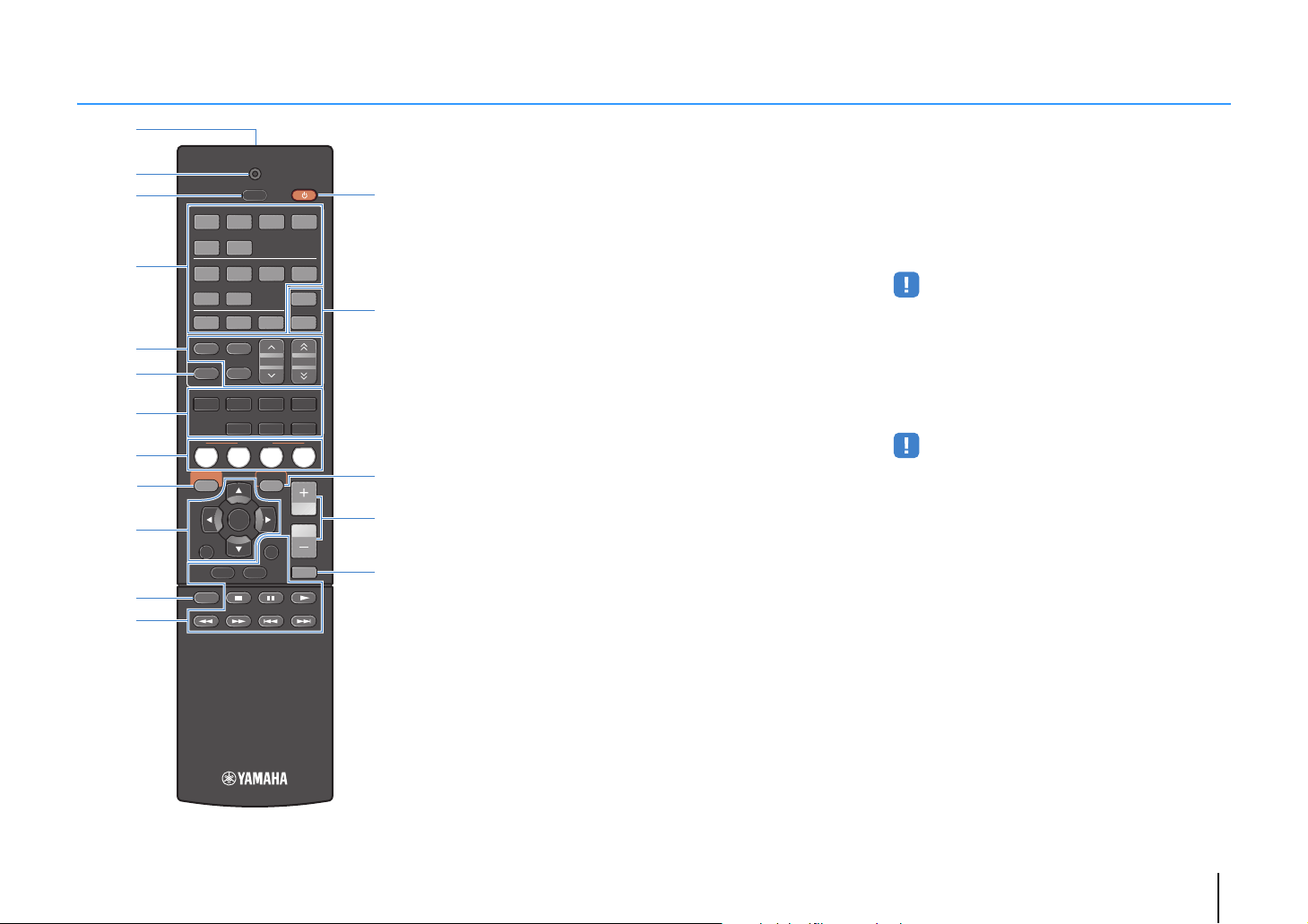
Remote control
1234
5 6
FM
INFO
MEMORY
AM
PRESET
TUNING
SCENE
RETURN
TOP
MENU
POP-UP
MENU
VOLUME
BD
DVD
TV
NET
RADIO
MUTE
DISPLAY
ENTER
TRANSMIT
RECEIVER
HDMI
AV
SLEEP
AUX USB
5 6
NET
ZONE B
ZONE A
MOVIE MUSIC
SUR. DECODE STRAIGHT
ENHANCER
BASS DIRECT
MODE
SETUP
OPTION
2341
C
D
E
F
G
1
4
2
3
5
6
8
7
9
:
B
A
1 Remote control signal transmitter
Transmits infrared signals.
2 TRANSMIT indicator
Lights up when remote control signals are transmitted.
3 SLEEP key
Switches the unit to standby mode automatically after a
specified period of time has elapsed (sleep timer). Press
repeatedly to set the time (120 min, 90 min, 60 min, 30 min,
off).
4 Input selection keys
Select an input source for playback.
HDMI 1–6 HDMI 1–6 jacks
AV 1 – 6 AV 1–6 jacks
AUX AUX jack (on the front panel)
USB USB jack (on the front panel)
NET Network sources (press repeatedly to select a
desired network source)
5 Radio keys
Operate the FM/AM radio (p.49).
FM Switches to FM radio.
AM Switches to AM radio.
MEMORY Registers FM/AM radio stations as presets.
PRESET Select a preset station.
TUNING Select the radio frequency.
6 INFO key
Selects the information displayed on the front display (p.71).
7 Sound mode keys
Select a sound mode (p.44).
8 SCENE keys
Select the registered input source and sound program with
one touch. Also, turns on the unit when it is in standby mode
(p.43).
9 SETUP key
Displays the setup menu (p.76).
0 Menu operation keys
Cursor keys Select a menu or a parameter.
ENTER Confirms a selected item.
RETURN Returns to the previous screen.
A MODE key
Switches between “Stereo” and “Mono” for FM radio
reception (p.49).
Switches the iPod operation modes (p.55).
B External device operation keys
Control playback of the iPod (p.53), USB storage device
(p.57) or PCs/NAS (p.60).
Also control playback or operate menus of the playback
devices connected to the unit with an HDMI cable.
• The playback devices must support HDMI Control. However,
Yamaha does not assure the operation of all HDMI
Control-compatible devices.
C RECEIVER z key
Turns on/off (standby) the unit.
D ZONE keys
Enable/disable the audio output to Zone A or Zone B (p.70).
• ZONE keys function on HTR-5067/TSR-5770 only.
E OPTION key
Displays the option menu (p.72).
F VOLUME keys
Adjust the volume.
G MUTE key
Mutes the audio output.
FEATURES ➤ Part names and functions En 10

PREPARATIONS
General setup procedure
1 Placing speakers (p.12)
2 Connecting speakers (p.16)
3 Connecting a TV (p.19)
4 Connecting playback devices (p.21)
5 Connecting the FM/AM antennas (p.24)
Connecting to a network (wired LAN
6
connection) (p.25)
7 Connecting recording devices (p.26)
8 Connecting the power cable (p.26)
Selecting an on-screen menu language
9
(p.27)
Connecting to a network wirelessly
10
(HTR-5067/TSR-5770 only) (p.28)
Select the speaker layout for the number of speakers that you are using and place them in your room.
Connect the speakers to the unit.
Connect a TV to the unit.
Connect video devices (such as BD/DVD players) and audio devices (such as CD players) to the unit.
Connect the supplied FM/AM antennas to the unit.
Connect the unit to a network with a commercially-available network cable.
Connect recording devices to the unit.
After all the connections are complete, plug in the power cable.
Select the desired on-screen menu language.
Connect the unit to a network wirelessly.
Optimizing the speaker settings
11
automatically (YPAO) (p.38)
This completes all the preparations. Enjoy playing movies, music, radio and other content with the unit!
Optimize the speaker settings, such as volume balance and acoustic parameters, to suit your room
(YPAO).
PREPARATIONS ➤ General setup procedure En 11
1 2 3 4 5 6 7 8 9 1011
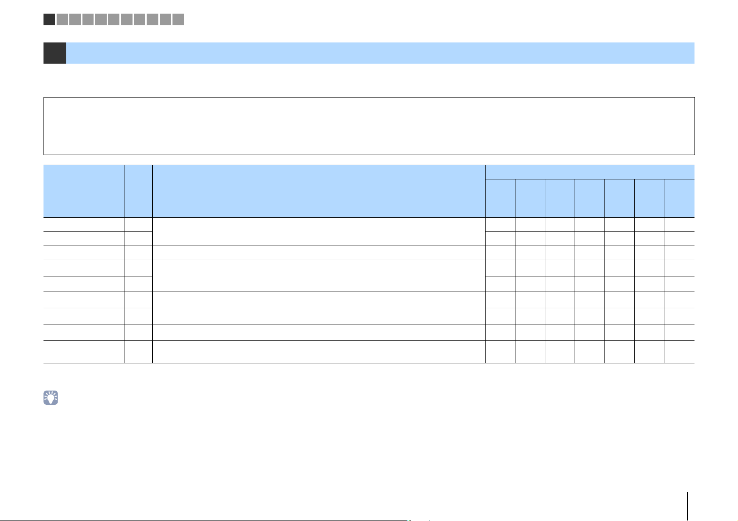
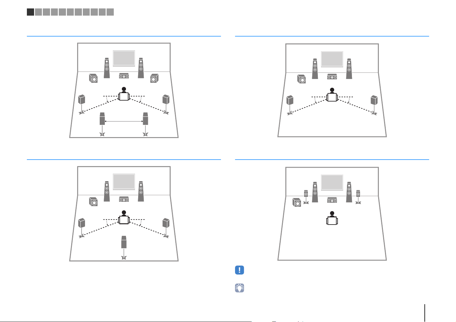
1 Placing speakers
Select the speaker layout for the number of speakers that you are using and place the speakers and subwoofer in your room. This section describes the representative speaker layout
examples.
Caution
• (U.S.A. and Canada models only)
Under its default settings, the unit is configured for 8-ohm speakers. When connecting 6-ohm speakers, set the unit’s speaker impedance to “6 Ω MIN”. For details, see “Setting the speaker impedance” (p.15).
• (Except for U.S.A. and Canada models)
Use speakers with an impedance of at least 6 Ω.
Speaker system (the number of channels)
Speaker type Abbr. Function
Front (L) 1
Front (R) 2 ●●●●●●●
Center 3 Produces center channel sounds (such as movie dialogue and vocals). ●●●● ●
Surround (L) 4
Surround (R) 5 ●●●
Surround back (L)*
Surround back (R)*
Surround back*
Subwoofer 9
1
1
1
Produce front left/right channel sounds (stereo sounds).
Produce surround left/right channel sounds.
6
Produce surround back left/right channel sounds.
7 ●
8 Produces sounds mixed from surround back left/right channel sounds. ●
Produces LFE (low-frequency effect) channel sounds and reinforces the bass parts of other channels.
This channel is counted as “0.1”.
7.1*16.1*
●●●●●●●
●●●
●
●●●●●●●
1
5.1
5.1
(Virtual
CINEMA
FRONT)
2
●*
2
●*
4.1 3.1 2.1
●
●
*1 HTR-5067/TSR-5770 only
*2 Place the surround speakers in front and set "Virtual CINEMA FRONT" (p.81) in the "Setup" menu to "On".
• HTR-5067/TSR-5770 supports 2- to 7.1-channel system, and HTR-4067 supports 2- to 5.1-channel speaker system.
• (HTR-5067/TSR-5770 only)
You can connect two subwoofers (with built-in amplifier) to the unit. Two subwoofers connected to the unit output the same sounds.
PREPARATIONS ➤ Placing speakers En 12
45
1
2
399
67
30 cm (1 ft) or
more
10° to 30°10° to 30°
45
1
2
39
8
10° to 30°10° to 30°
45
12
39
10° to 30°10° to 30°
12
39
45
1 2 3 4 5 6 7 8 9 1011
7.1-channel system (HTR-5067/TSR-5770 only)
6.1-channel system (HTR-5067/TSR-5770 only)
5.1-channel system
5.1-channel system (Virtual CINEMA FRONT)
• To utilize this configuration, set "Virtual CINEMA FRONT" (p.78) in the "Setup" menu to "On".
• You can enjoy surround sound even without the center speaker (front 4.1-channel system).
PREPARATIONS ➤ Placing speakers En 13
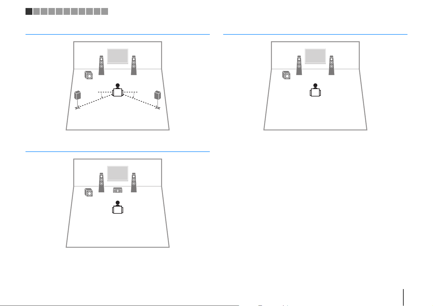
45
12
9
10° to 30°10° to 30°
12
39
12
9
1 2 3 4 5 6 7 8 9 1011
4.1-channel system
3.1-channel system
2.1-channel system
PREPARATIONS ➤ Placing speakers En 14

z (power)
STRAIGHT
1 2
PARTY
VIRTUAL
VOL.
MUTE
ENHANCER
STEREO
TUNED
SLEEP
OUT
ECO
CHARGE
ADAPTIVE DRC
ZONE2AZONE
3B
SP IMP.••8¬MIN
1 2 3 4 5 6 7 8 9 1011
■ Setting the speaker impedance
(U.S.A. and Canada models only)
Under its default settings, the unit is configured for 8-ohm speakers. When connecting
6-ohm speakers, set the speaker impedance to “6 Ω MIN”.
Before connecting speakers, connect the power cable to an AC wall
1
outlet.
While holding down STRAIGHT on the front panel, press z (power).
2
Check that “SP IMP.” is displayed on the front display.
3
Press STRAIGHT to select “6 Ω MIN”.
4
Press z (power) to set the unit to standby mode and remove the
5
power cable from the AC wall outlet.
You are now ready to connect the speakers.
PREPARATIONS ➤ Placing speakers En 15
–
+
–
+
FRONT CENTER SURROUND
SINGLE
SURROUND BACK/BI AMP
/ZONE B
OR OUT
P
B
Y
SPEAKERS
SUBWOOFER
PRE OUT
2
1
DC OUT
5V 0.5A
12
3
45
9
The unit (rear)
• (HTR-5067/TSR-5770 only)
You can connect 2 subwoofers (with built-in amplifier) to the unit.
The 2 subwoofers output the same sound.
FRONT CENTER SURROUND
SINGLE
SURROUND BACK/BI AMP
/ZONE B
OR OUT
P
B
Y
SPEAKERS
SUBWOOFER
PRE OUT
2
1
DC OUT
5V 0.5A
1
67
2
3
45
9
9
The unit (rear)
• When using only one surround back speaker, connect it to the
SINGLE jack (L side).
1 2 3 4 5 6 7 8 9 1011
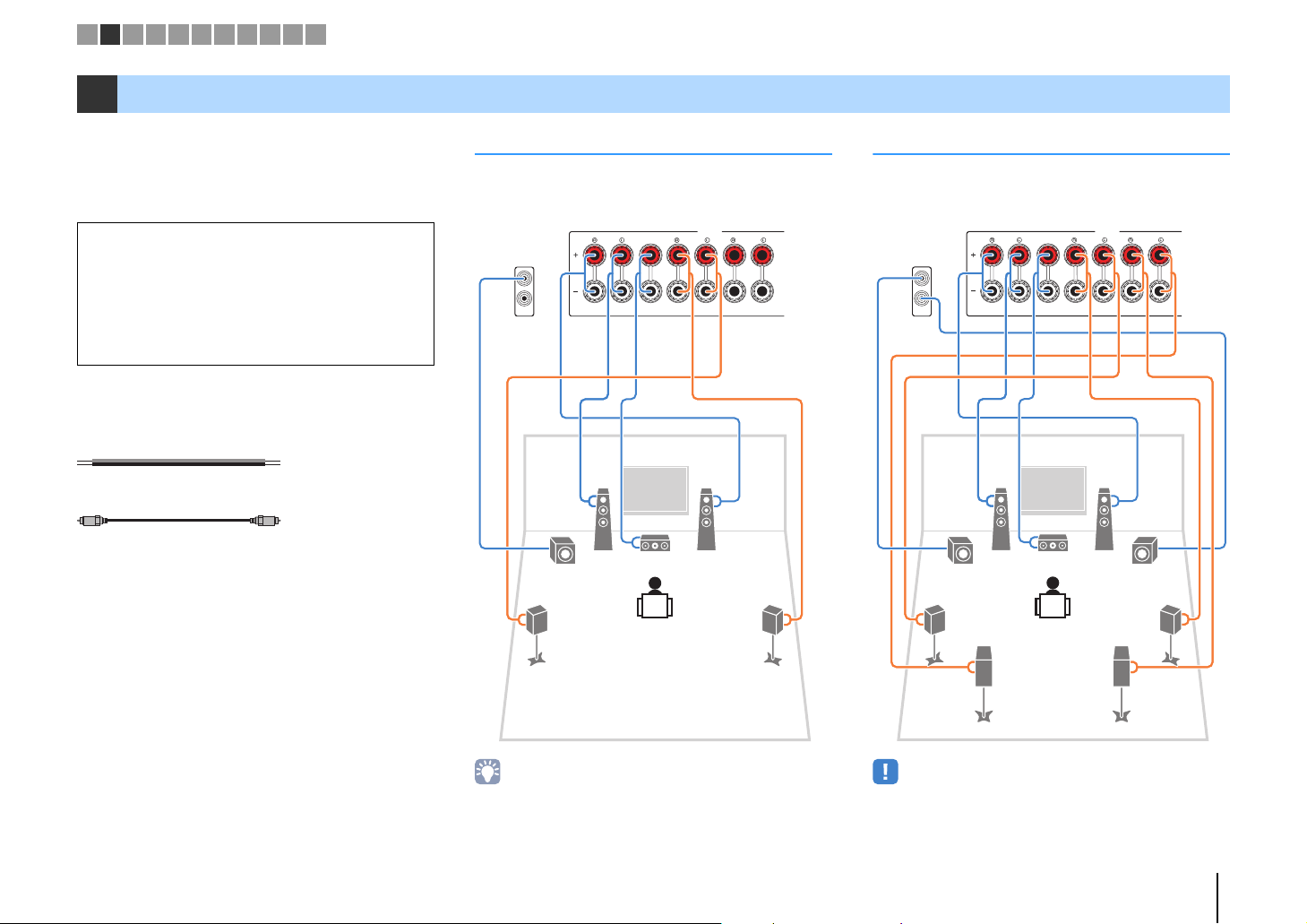
2 Connecting speakers
Connect the speakers placed in your room to the unit.
The following diagrams provide connections for 5.1and 7.1-channel systems as examples. For other
systems, connect speakers while referring to the
connection diagram for the 5.1-channel system.
Caution
• Remove the unit’s power cable from an AC wall outlet and turn
off the subwoofer before connecting the speakers.
• Ensure that the core wires of the speaker cable do not touch
one another or come into contact with the unit’s metal parts.
Doing so may damage the unit or the speakers. If the speaker
cables short circuit, “Check SP Wires” will appear on the front
display when the unit is turned on.
Cables required for connection
(commercially available)
Speaker cables (x the number of speakers)
Audio pin cable (x1: for connecting a subwoofer)
5.1-channel system 7.1-channel system
(HTR-5067/TSR-5770 only)
PREPARATIONS ➤ Connecting speakers En 16
FRONT
aa
b
d
c
+ (red)
- (black)
FRONT
a
b
Banana plug
AV
OUT
2
1
Audio pin cable
12
3
45
9
The unit (rear)
1 2 3 4 5 6 7 8 9 1011
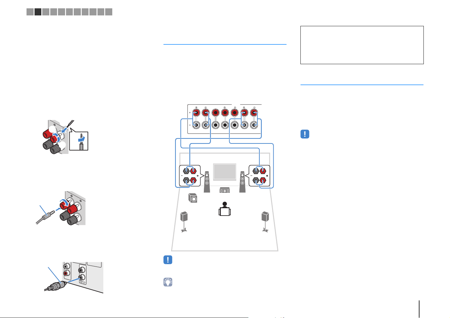
■ Connecting speaker cables
Speaker cables have two wires. One is for connecting
the negative (-) terminal of the unit and the speaker, and
the other is for the positive (+) terminal. If the wires are
colored to prevent confusion, connect the black wire to
the negative and the other wire to the positive terminal.
a Remove approximately 10 mm (3/8”) of insulation from
the ends of the speaker cable and twist the bare wires of
the cable firmly together.
b Loosen the speaker terminal.
c Insert the bare wires of the cable into the gap on the side
(upper right or bottom left) of the terminal.
d Tighten the terminal.
Using a banana plug
(U.S.A., Canada, China, Australia and General models only)
a Tighten the speaker terminal.
b Insert a banana plug into the end of the terminal.
Connecting front speakers that support bi-amp connections
(HTR-5067/TSR-5770 only)
When using front speakers that support bi-amp
connections, connect them to the FRONT jacks and
SURROUND BACK/BI-AMP/ZONE B jacks.
To enable the bi-amp function, set “Power Amp Assign”
(p.79) in the “Setup” menu to “BI-AMP” after connecting
the power cable to an AC wall outlet.
SPEAKERS
SURROUND BACK/BI AMP
FRONT CENTER SURROUND
/ZONE B
SINGLE
Caution
• Before making bi-amp connections, remove any brackets or
cables that connect a woofer with a tweeter. Refer to the
instruction manual of the speakers for details. If you are not
making bi-amp connections, make sure that the brackets or
cables are connected before connecting the speaker cables.
Connecting Zone B speakers
(HTR-5067/TSR-5770 only)
The Zone A/B function allows you to playback an input
source in the room where the unit is installed (Zone A)
and in another room (Zone B). To connect the Zone B
speakers, see “Playing back music in multiple rooms
(HTR-5067/TSR-5770 only)” (p.69).
• Surround back speakers or bi-amplified front speakers cannot be
used while the Zone B function is enabled.
■ Connecting the subwoofer
(with built-in amplifier)
Use an audio pin cable to connect the subwoofer.
• Surround back speakers or Zone B speakers cannot be used during
bi-amp connections.
• The FRONT jacks and SURROUND BACK/BI-AMP/ZONE B jacks
output the same signals.
PREPARATIONS ➤ Connecting speakers En 17
Input/output jacks and cables
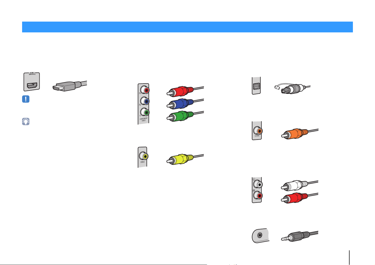
HDMI cable
Component video cable
Video pin cable
OPTICAL
Digital optical cable
Digital coaxial cable
Stereo pin cable
Stereo mini-plug cable
■ Video/audio jacks
❑ HDMI jacks
Transmit digital video and digital sound through a single
jack. Use an HDMI cable.
• Use a 19-pin HDMI cable with the HDMI logo. We recommend using
a cable less than 5.0 m (16.4 ft) long to prevent signal quality
degradation.
• The unit’s HDMI jacks support the HDMI Control, Audio Return
Channel (ARC), and 3D and 4K Ultra HD video transmission
(through output) features.
• Use high speed HDMI cables to enjoy 3D or 4K Ultra HD videos.
■ Video jacks
❑ COMPONENT VIDEO jacks
Transmit video signals separated into three
components: luminance (Y), chrominance blue (P
and chrominance red (P
cable with three plugs.
R). Use a component video
❑ VIDEO jacks
Transmit analog video signals. Use a video pin cable.
B),
■ Audio jacks
❑ OPTICAL jacks
Transmit digital audio signals. Use a digital optical
cable. Remove the tip protector (if available) before
using the cable.
❑ COAXIAL jacks
Transmit digital audio signals. Use a digital coaxial
cable.
❑ AUDIO jacks
(Stereo L/R jacks)
Transmit analog stereo audio signals. Use a stereo pin
cable (RCA cable).
(Stereo mini jack)
Transmits analog stereo audio signals. Use a stereo
mini-plug cable.
PREPARATIONS ➤ Input/output jacks and cables En 18
M
3
The unit (rear)
HDMI OUT jack
AV 1 (OPTICAL) jack
Audio output
(digital optical)
TV
HDMI input
U
5
The unit (rear)
MONITOR OUT
(COMPONENT VIDEO) jacks
Video input
(component video)
AV 1 (OPTICAL) jack
Audio output
(digital optical)
TV
1 2 3 4 5 6 7 8 9 1011
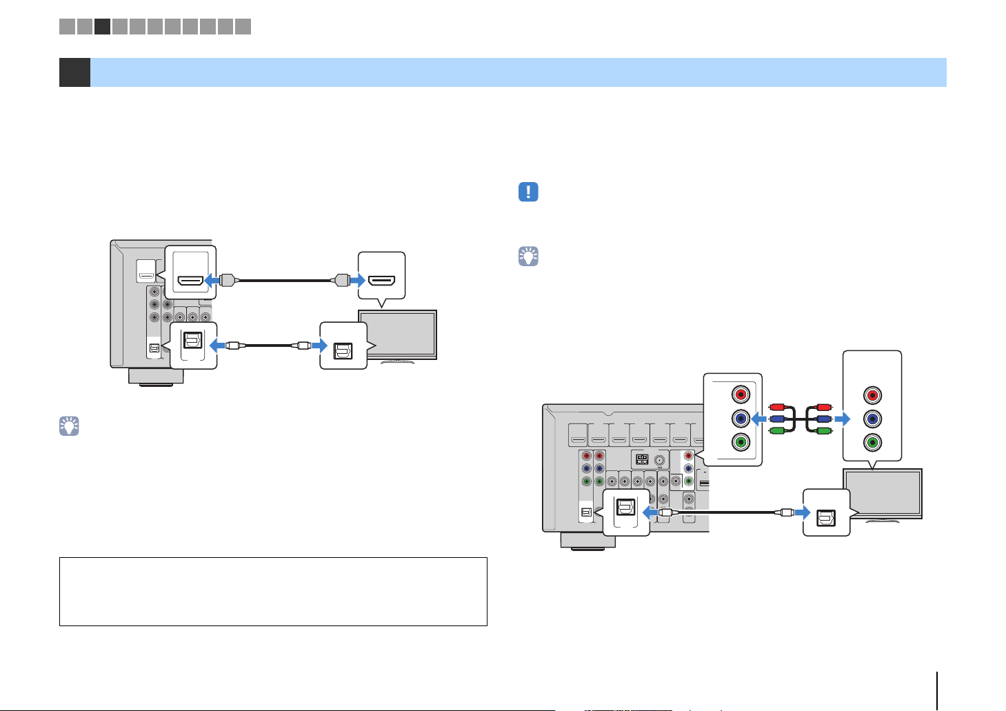
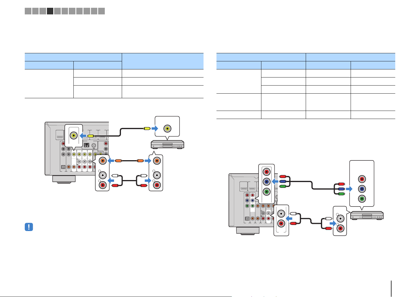
3 Connecting a TV
Connect a TV to the unit so that video input to the unit can be output to the TV. You can
also enjoy playback of TV audio on the unit.
To maximize the performance of the unit, we recommend connecting a TV with an HDMI
cable.
■ HDMI connection
Connect the TV to the unit with an HDMI cable and a digital optical cable.
OUT
HDMI
HDMI 2
HDMI
HDMI 1
(
)
OUT
HDMI
BD/DVD
ARC
P
R
P
B
Y
COMPONENT
VIDEO
OPTICAL COAXIAL COAXIAL
(
)
TV
AV 2
AV 1
ARC
HDMI
A
VIDEO
OPTICAL
(TV)
AV 3
AV 1
OO
AV 5
AV 4
OPTICAL
• You do not make a digital optical cable connection between the TV and the unit in the following cases:
– If your TV supports Audio Return Channel (ARC)
– If you will receive TV broadcasts only from the set-top box
• If you connect a TV that suppor ts HDMI Control to the unit with an HDMI cable, you can control the unit’s
power and volume with the TV’s remote control.
To use HDMI Control and ARC, you need to configure the HDMI settings on the unit. For
details on the settings, see “Information on HDMI” (p.111).
About Audio Return Channel (ARC)
• ARC allows audio signals to travel both ways. If you connect a TV that supports ARC to the unit with a
single HDMI cable, you can output video/audio to the TV or input TV audio to the unit.
• When using ARC, connect a TV with an HDMI cable that supports ARC.
HDMI
HDMI
■ Component / composite video connection
When connecting any video device with a component video cable, connect the TV to
the MONITOR OUT (COMPONENT VIDEO) jacks.
When connecting any video device with a video pin cable, connect the TV to the
MONITOR OUT (VIDEO) jack.
• If you connect your TV to the unit with a cable other than HDMI, video input to the unit via HDMI cannot be
output to the TV.
• Operations with TV screen are available only when your TV is connected to the unit via HDMI.
• If you will receive TV broadcasts only from the set-top box, you do not need to make an audio cable
connection between the TV and the unit.
❑ COMPONENT VIDEO connection (with a component video cable)
COMPONENT
VIDEO
PR
P
R
PB
P
B
Y
Y
OUT
HDMI
ARC
P
R
P
B
Y
COMPONENT
VIDEO
OPTICAL COAXIAL COAXIAL
(
AV 1
COMPONENT
VIDEO
PR
HDMI 4
HDMI 2
HDMI 1
(
)
BD/DVD
VIDEO
OPTICAL
)
TV
AV 2
AV 3
AV 4
(TV)
AV 1
HDMI 5
HDMI 3
ANTENNA
(
)
RADIO
AM
AV 5
AV 6
HDMI 6
PB
FM
COMPONENT
VIDEO
P
R
P
B
Y
MONITOR OUT
OO
SUBWOOFER
AV
PRE OUT
OUT
Y
MONITOR OUT
DC O
5V 0.
1
2
P
R
P
B
Y
OPTICAL
PREPARATIONS ➤ Connecting a TV En 19
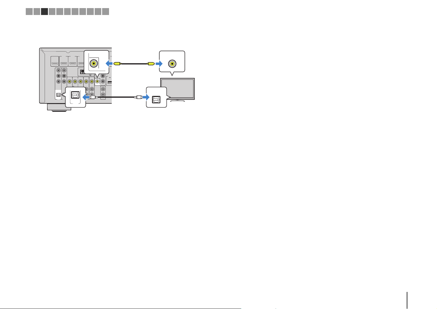
U
5
The unit (rear)
MONITOR OUT
(VIDEO) jack
Video input
(composite video)
Audio output
(digital optical)
TV
AV 1 (OPTICAL) jack
1 2 3 4 5 6 7 8 9 1011
❑ VIDEO (composite video) connection (with a video pin cable)
HDMI 4
OUT
HDMI
ARC
P
R
P
B
Y
COMPONENT
VIDEO
OPTICAL COAXIAL COAXIAL
HDMI 2
HDMI 1
(
)
BD/DVD
VIDEO
(
)
TV
AV 2
AV 3
AV 4
AV 1
OPTICAL
(TV)
AV 1
HDMI 5
HDMI 3
ANTENNA
(
)
RADIO
AM
AV 6
AV 5
HDMI 6
V
FM
COMPONENT
MONITOR OUT
VIDEO
P
R
DC O
5V 0.
P
B
Y
MONITOR OUT
1
2
OO
SUBWOOFER
AV
PRE OUT
OUT
VIDEO
V
OPTICAL
PREPARATIONS ➤ Connecting a TV En 20
The unit (rear)
HDMI output
Video device
HDMI 1–6 jacks
M
3
The unit (rear)
AV 1–2
(COMPONENT VIDEO)
jacks
Video output
(component video)
Video device
Audio output
(digital optical or digital coaxial)
AV 1 (OPTICAL) jack or
AV 2 (COAXIAL) jack
1 2 3 4 5 6 7 8 9 1011
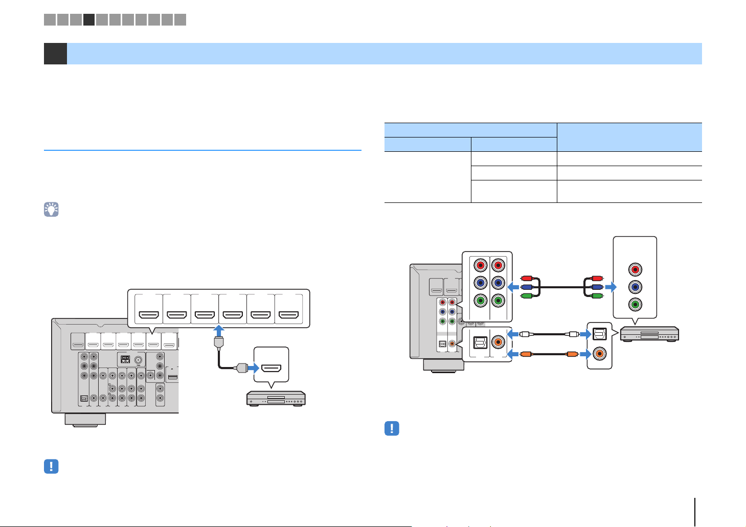
4 Connecting playback devices
The unit is equipped with a variety of input jacks including HDMI input jacks to allow
you to connect different types of playback devices. For information on how to connect
an iPod or a USB storage device, see the following pages.
– Connecting an iPod (p.53)
– Connecting a USB storage device (p.57)
Connecting video devices (such as BD/DVD players)
Connect video devices such as BD/DVD players, set-top boxes (STBs) and game
consoles to the unit. Depending on the video/audio output jacks available on your video
device, choose one of the following connections. We recommend using an HDMI
connection if the video device has an HDMI output jack.
• If the combination of video/audio input jacks available on the unit does not match your video device, change
■ HDMI connection
Connect a video device to the unit with an HDMI cable.
its combination according to the output jacks of your device (p.22).
HDMI 1
HDMI 2 HDMI 3 HDMI 4
(
)
BD/DVD
HDMI 4
HDMI 2
HDMI 1
(
)
OUT
HDMI
BD/DVD
ARC
P
R
P
B
Y
COMPONENT
VIDEO
VIDEO
OPTICAL COAXIAL COAXIAL
(
)
TV
AV 2
AV 3
AV 4
AV 1
HDMI 5
HDMI 3
ANTENNA
(
)
RADIO
AM
AV 6
AV 5
HDMI 6
FM
COMPONENT
VIDEO
P
R
P
B
Y
MONITOR OUT
1
2
SUBWOOFER
AV
PRE OUT
OUT
HDMI
DC OUT
5V 0.5A
HDMI
HDMI 5 HDMI 6
HDMI
■ Component video connection
Connect a video device to the unit with a component video cable and an audio cable
(digital optical or digital coaxial). Choose a set of input jacks (on the unit) depending on
the audio output jacks available on your video device.
Output jacks on video device
Video Audio
Digital optical AV 1 (COMPONENT VIDEO + OPTICAL)
Component video
Digital coaxial AV 2 (COMPONENT VIDEO + COAXIAL)
Analog Stereo
P
R
HDMI 2
OUT
HDMI
ARC
P
R
P
B
Y
COMPONENT
VIDEO
OPTICAL COAXIAL COAXIAL
AV 1
HDMI 1
(
BD/DVD
(
)
TV
HDMI
)
P
B
A
Y
COMPONENT
VIDEO
VIDEO
R
P
P
B
Y
O
OPTICAL
AV 2
AV 3
COAXIAL
AV 5
AV 4
( TV )
AV 1
C
AV 2
If you select the input source by pressing AV 1–2, the video/audio played back on the
video device will be output from the unit.
Input jacks on the unit
You need to change the combination of
video/audio input jacks (p.22).
COMPONENT
VIDEO
PR
R
P
PB
P
B
Y
Y
O
OPTICAL
C
COAXIAL
If you select the input source by pressing HDMI 1–6, the video/audio played back on
the video device will be output from the unit.
• To watch videos input to the HDMI 1–6 jacks, you need to connect your TV to the HDMI OUT jack of the
unit (p.19 to 21).
• To watch videos input to the AV 1–2 (COMPONENT VIDEO) jacks, you need to connect your TV to the
MONITOR OUT (COMPONENT VIDEO) jacks of the unit (p.21).
PREPARATIONS ➤ Connecting playback devices En 21
The unit (rear)
AV 3–6 (VIDEO) jack
Video output
(composite video)
Video device
Audio output
(digital coaxial or analog stereo)
Any of AV 3 (COAXIAL) jack,
AV 4–6 (AUDIO) jacks
M
M
AV 2 (COMPONENT VIDEO) jacks
Video output
(component video)
AV 5 (AUDIO) jacks
Video device
Audio output
(analog stereo)
The unit (rear)
1 2 3 4 5 6 7 8 9 1011
■ Composite video connection
Connect a video device to the unit with a video pin cable and an audio cable (digital
coaxial or stereo pin cable). Choose a set of input jacks (on the unit) depending on the
audio output jacks available on your video device.
Output jacks on video device
Video Audio
Digital coaxial AV 3 (VIDEO + COAXIAL)
Composite video
Analog stereo AV 4–6 (VIDEO + AUDIO)
Digital optical
HDMI 4
ANTENNA
AM
V
(
)
RADIO
FM
AV 6
HDMI 5
COMPONENT
VIDEO
P
R
P
B
Y
MONITOR OUT
COAXIAL
SUBWOOFER
AV
PRE OUT
OUT
L
R
1
CC
2
L
R
HDMI 2
HDMI 3
HDMI 1
(
)
OUT
HDMI
BD/DVD
ARC
VIDEO
P
R
P
B
Y
COMPONENT
VIDEO
VIDEO
OPTICAL COAXIAL COAXIAL
(
)
TV
AV 2
AV 5
AV 3
AV 4
AV 1
If you select the input source by pressing AV 3–6, the video/audio played back on the
video device will be output from the unit.
• To watch videos input to the AV 3–6 (VIDEO) jacks, you need to connect your TV to the MONITOR OUT
(VIDEO) jack of the unit (p.21).
Input jacks on the unit
You need to change the combination of
video/audio input jacks (p.22).
VIDEO
V
COAXIAL
L
L
R
R
■ Changing the combination of video/audio input jacks
If the combination of video/audio input jacks available on the unit does not match your
video device, change its combination according to the output jacks of your device. You
can connect a video device that has the following video/audio output jacks.
Output jacks on video device Input jacks on the unit
Video Audio Video Audio
Digital optical HDMI 1–6 AV 1 (OPTICAL)
HDMI
Component video Analog stereo
Composite video Digital optical AV 3–6 (VIDEO) AV 1 (OPTICAL)
❑ Necessary setting
For example, if you have connected a video device to AV 2 (COMPONENT VIDEO) and
AV 5 (AUDIO) jacks of the unit, change the combination setting as follows.
HDMI 1
(
OUT
HDMI
BD/DVD
ARC
P
R
P
B
Y
COMPONENT
VIDEO
OPTICAL COAXIAL COAXIAL
(
)
TV
AV 2
AV 1
Digital coaxial HDMI 1–6 AV 2–3 (COAXIAL)
Analog stereo HDMI 1–6 AV 4–6 (AUDIO)
AV 1–2
(COMPONENT
VIDEO)
COMPONENT
R
P
HDMI 2
)
VIDEO
AV 3
HD
HDMI 3
P
B
Y
ANTENNA
(
)
RADIO
F
AM
L
AV 5
AV 6
AV 4
R
AV 5
R
L
P
P
AUDIO
L
R
R
B
Y
AV 4–6 (AUDIO)
VIDEO
PR
PB
Y
PREPARATIONS ➤ Connecting playback devices En 22
1234
5 6
AV
AUX USB
5 6
NET
ZONE B
ZONE A
RETURN
VOLUME
BD
DVD
TV
NET
RADIO
DISPLAY
ENTER
SETUP
OPTION
RETURN
VOLUME
BD
RADIO
DISPLAY
SETUP
ENTER
OPTION
134
5
6
AV
USB
5
6
ZONE A
AV 2
Cursor keys
MUTE
ENHANCER
STEREO
TUNED
SLEEP
OUT
ECO
CHARGE
ADAPTIVE DRC
VIRTUAL
Audio In
VOL.
MUTE
ENHANCER
STEREO
TUNED
SLEEP
OUT
ECO
CHARGE
ADAPTIVE DRC
VIRTUAL
Audio••••••AV5
VOL.
H
Audio output
(either digital optical,
digital coaxial, or analog stereo)
AV 1–6 jacks
The unit (rear)
Audio device
1 2 3 4 5 6 7 8 9 1011
After connecting external devices (such as a TV and playback
1
devices) and power cable of the unit, turn on the unit.
Press AV 2 to select “AV 2” (video input jack to be used) as the input
2
source.
Press OPTION.
3
Use the cursor keys (q/w) to select “Audio In” and press ENTER.
4
Use the cursor keys (e/r) to select “AV 5” (audio input jack to be
5
used).
Connecting audio devices (such as CD players)
Connect audio devices such as CD players and MD players to the unit. Depending on
the audio output jacks available on your audio device, choose one of the following
connections.
Audio output jacks on audio device Audio input jacks on the unit
Digital optical AV 1 (OPTICAL)
Digital coaxial AV 2–3 (COAXIAL)
Analog stereo AV 4–6 (AUDIO)
HDMI 4
HDMI 2
HDMI 1
(
)
OUT
HDMI
BD/DVD
ARC
P
R
P
B
Y
COMPONENT
VIDEO
VIDEO
OPTICAL COAXIAL COAXIAL
(
)
TV
AV 2
AV 3
AV 4
AV 1
If you select the input source by pressing AV 1–6, the audio played back on the audio
device will be output from the unit.
HDMI 5
HDMI 3
ANTENNA
(
)
RADIO
FM
AM
COMPONENT
VIDEO
MONITOR OUT
L
R
AV
OUT
AV 6
AV 5
OO
OPTICAL
P
R
P
B
COAXIAL
CC
Y
1
L
2
SUBWOOFER
PRE OUT
R
OPTICAL
COAXIAL
L
L
R
R
Press OPTION.
6
This completes the necessary settings.
If you select “AV 2” as the input source by pressing AV 2, the video/audio played back
on the video device will be output from the unit.
PREPARATIONS ➤ Connecting playback devices En 23

SCENE
Portable audio player
The unit (front)
FM antenna
AM antenna
The unit (rear)
Hold down Insert Release
1 2 3 4 5 6 7 8 9 1011
Connecting to the jack on the front panel
Use the AUX jack on the front panel to temporarily connect devices such as portable
audio players to the unit.
Before making a connection, stop playback on the device and turn down the volume on
the unit.
BD
TV
DVD
CONTROL
INPUT
TONE
PROGRAM
If you select “AUX” as the input source by pressing AUX, the audio played back on the
device will be output from the unit.
• You need to prepare the audio cable that matches the output jacks on your device.
• For details on how to connect an iPod or a USB storage device, see “Connecting an iPod” (p.53) or
“Connecting a USB storage device” (p.57).
RADIO
NET
STRAIGHT
AUX
5V 1A
AUDIO
5 Connecting the FM/AM antennas
Connect the supplied FM/AM antennas to the unit.
Fix the end of the FM antenna to a wall, and place the AM antenna on a flat surface.
HDMI 4
HDMI 2
HDMI 1
(
)
OUT
HDMI
BD/DVD
ARC
P
R
P
B
Y
COMPONENT
VIDEO
VIDEO
OPTICAL COAXIAL COAXIAL
(
)
TV
AV 2
AV 3
AV 4
AV 1
Assembling and connecting the AM antenna
HDMI 5
HDMI 3
ANTENNA
(
)
RADIO
FM
AM
COMPONENT
AV
OUT
AV 5
AV 6
VIDEO
MONITOR OUT
P
P
R
B
Y
SUBWOOFER
PRE OUT
NETWORK
HDMI 6
(
)
NET
DC OUT
5V 0.5A
FRONT CENTER SURROUND
1
2
SPEAKERS
SURROUND BACK/BI AMP
/ZONE B
SINGLE
• Unwind only the length of cable needed from the AM antenna unit.
• The wires of the AM antenna have no polarity.
PREPARATIONS ➤ Connecting the FM/AM antennas En 24
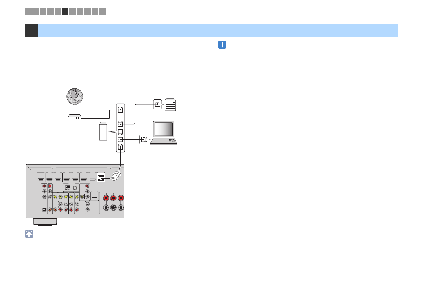
Network Attached Storage
(NAS)
Internet
Modem
Router
Network cable
PC
The unit (rear)
1 2 3 4 5 6 7 8 9 1011
6 Connecting to a network (wired LAN connection)
Connect the unit to your router with a commercially-available STP network cable (CAT-5
or higher straight cable).
You can enjoy Internet radio or music files stored on media servers, such as PCs and
Network Attached Storage (NAS), on the unit.
(HTR-5067/TSR-5770 only)
You can also connect the unit to a network wirelessly. For details, see "Connecting to a
network wirelessly (HTR-5067/TSR-5770 only)" (p.28).
WAN
LAN
• Some security software installed on your PC or the firewall settings of network devices (such as a router)
may block the access of the unit to the network devices or the Internet. In these cases, configure the
security software or firewall settings appropriately.
• Each ser ver must be connected to the same subnet as the unit.
• To use the service via the Internet, broadband connection is strongly recommended.
OUT
HDMI
ARC
P
R
P
B
Y
COMPONENT
VIDEO
OPTICAL COAXIAL COAXIAL
(
AV 1
HDMI 4
HDMI 3
AM
AV 5
ANTENNA
(
)
RADIO
AV 6
HDMI 5
NETWORK
HDMI 6
(
)
NET
FM
COMPONENT
VIDEO
P
R
DC OUT
5V 0.5A
P
B
Y
MONITOR OUT
1
2
SUBWOOFER
AV
PRE OUT
OUT
HDMI 2
HDMI 1
(
)
BD/DVD
VIDEO
)
TV
AV 2
AV 3
AV 4
FRONT CENTER
• If you are using a router that supports DHCP, you do not need to configure any network settings for the unit,
as the network parameters (such as the IP address) will be assigned automatically to it. You only need to
configure the network settings if your router does not support DHCP or if you want to configure the network
parameters manually (p.91).
• You can check whether the network parameters (such as IP address) are properly assigned to the unit in
“Information” (p.91) in the “Setup” menu.
PREPARATIONS ➤ Connecting to a network (wired LAN connection) En 25
The unit (rear)
AV OUT jacks
Video/audio input
Video recording
device
VOLTAGE
SELECTOR
110V–
120V
220V–
240V
The unit (rear)
VOLTAGE SELECTOR
To an AC wall outlet
The unit (rear)
1 2 3 4 5 6 7 8 9 1011
7 Connecting recording devices
You can connect video/audio recording devices to the AV OUT jacks. These jacks
output analog video/audio signals selected as the input.
• To copy video/audio from a video device, connect the video device to the AV 4–6 jacks of the unit.
• To copy audio from an audio device, connect the audio device to the AV 4–6 jacks or AUX jack of the unit.
• Be sure to use the AV OUT jacks only for connecting recording devices.
VIDEO
V
V
HDMI 4
OUT
HDMI
ARC
P
R
P
B
Y
COMPONENT
VIDEO
OPTICAL COAXIAL COAXIAL
(
AV 1
HDMI 2
HDMI 1
(
)
BD/DVD
VIDEO
)
TV
AV 2
AV 3
AV 4
HDMI 5
HDMI 3
L
ANTENNA
(
)
RADIO
FM
AM
COMPONENT
VIDEO
P
R
P
B
Y
MONITOR OUT
SUBWOOFER
AV
PRE OUT
OUT
AV 5
AV 6
R
AV
OUT
1
2
L
L
R
R
AUDIO
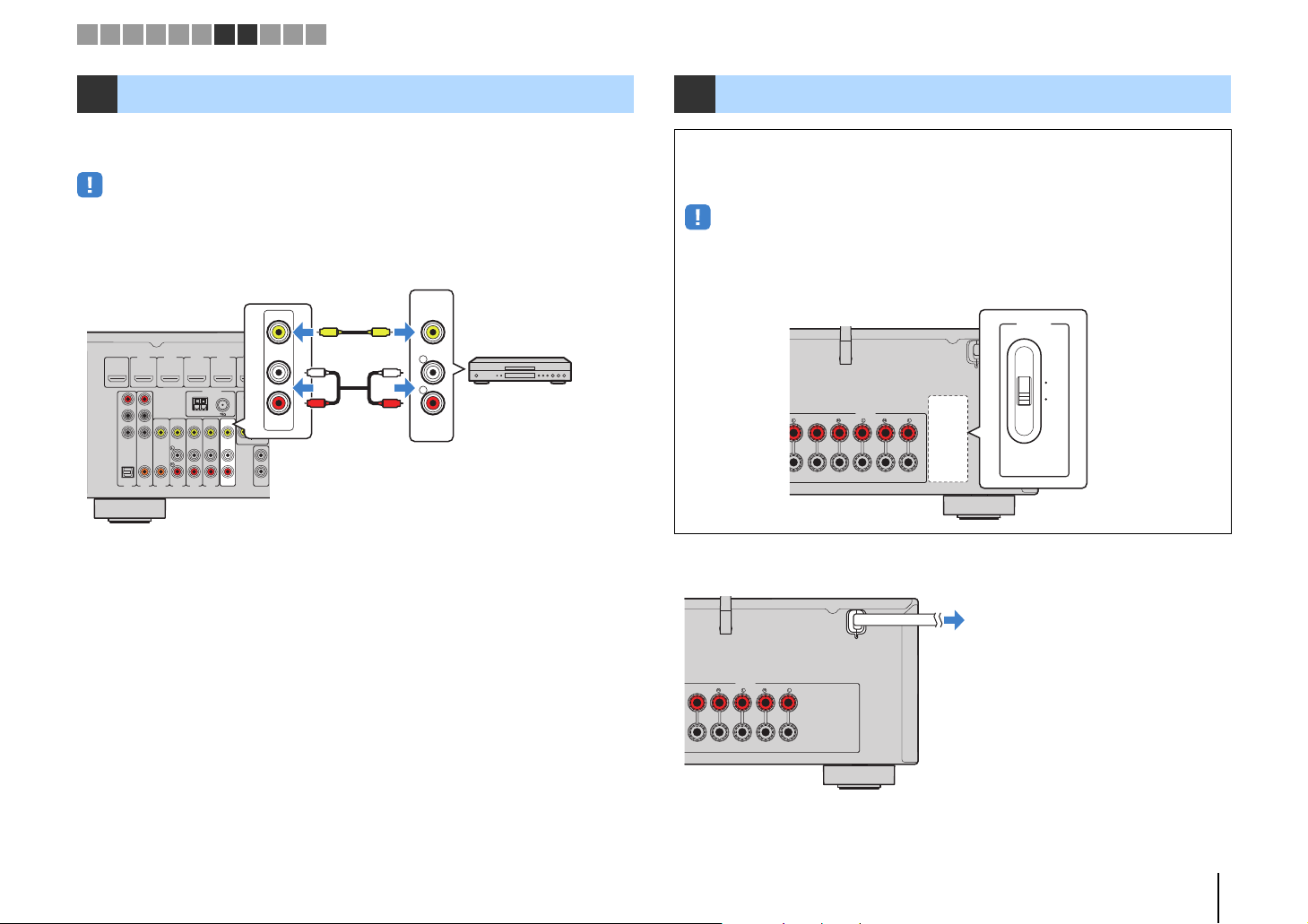
8 Connecting the power cable
Before connecting the power cable (General model only)
Set the switch position of VOLTAGE SELECTOR according to your local voltage.
Voltages are AC 110–120/220–240 V, 50/60 Hz.
• Make sure you set VOLTAGE SELECTOR of the unit BEFORE plugging the power cable into an AC
wall outlet. Improper setting of VOLTAGE SELECTOR may cause damage to the unit and create a
potential fire hazard.
SPEAKERS
SURROUND BACK/BI AMP
CENTER SURROUND
After all the connections are complete, plug in the power cable.
/ZONE B
SINGLE
CENTER SURROUND
SPEAKERS
SURROUND BACK/BI AMP
/ZONE B
SINGLE
PREPARATIONS ➤ Connecting recording devices En 26
Setup
Speaker
HDMI
Sound
ECO
Function
Network
Language
English
日本語
Français
Deutsch
Español
Русский
Italiano
中文
Setup
Speaker
HDMI
Sound
ECO
Function
Network
Language
English
日本語
Français
Deutsch
Español
Русский
Italiano
中文
1 2 3 4 5 6 7 8 9 1011
1
234
5
6
Y
PRESETTU
G
S
E
RETURN
TO
MENU
POP-U
MENU
D
O
MUTE
DISPLAY
T
S
P
AUXUSB
5
6
ZO
A
C
S
E
BASS
MODE
N
234
1
TRANSMIT
TRANSMI
RECEIVER
P
ZONE A
ZONE
ZONE B
NE B
TUNING
DIRECT
RADIO
RADI
VOLUME
VOLUME
MUTE
RECEIVER z RECEIVER z
NIN
SETUP
Cursor keys
ENTER
SLEEP
LEE
HDMI
2341
5 6
AV
1234
5 6
AUX USB
FM
INFO
INFO
MOVIE MUSIC
MOVIEMUSI
BD
B
DVD
SETUP
RETURN
TOP
MENU
MODE
AM
MEMORY
MEMOR
BASS DIRECT
SCENE
CEN
TV
ENTER
P
NET
PRESET
SUR. DECODE STRAIGHT
UR. DECODESTRAIGHT
NHANCER
ENHANCER
NET
OPTIO
OPTION
DISPLAY
POP-UP
MENU
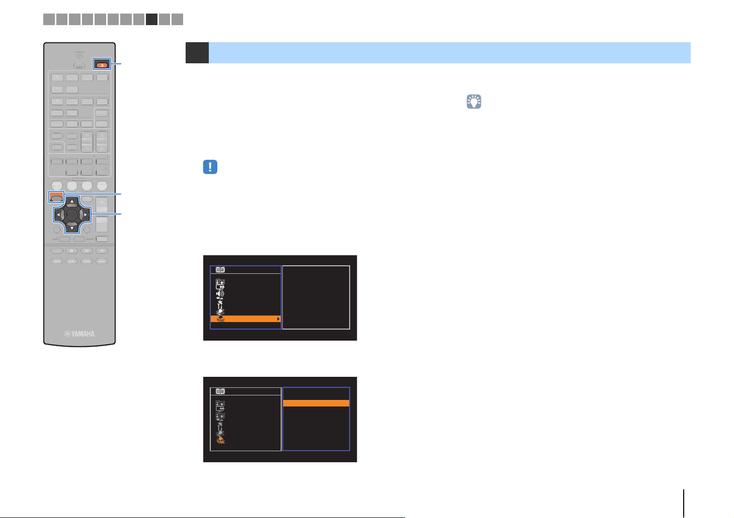
9 Selecting an on-screen menu language
Select the desired on-screen menu language from English
(default), Japanese, French, German, Spanish, Russian, Italian and
Chinese.
Press RECEIVER z to turn on the unit.
1
Turn on the TV and switch the TV input to display
2
video from the unit (HDMI OUT jack).
• Operations with TV screen are available only when your TV is connected to
the unit via HDMI. If not, carry out operations while viewing the front display.
Press SETUP.
3
Use the cursor keys to select “Language” and press
4
ENTER.
To exit from the menu, press SETUP.
6
• The information on the front display is provided in English only.
Use the cursor keys to select the desired language.
5
PREPARATIONS ➤ Selecting an on-screen menu language En 27
Screw in
Bend
Turn clockwise to the vertical position
Joint
StrongWeak
1 2 3 4 5 6 7 8 9 1011
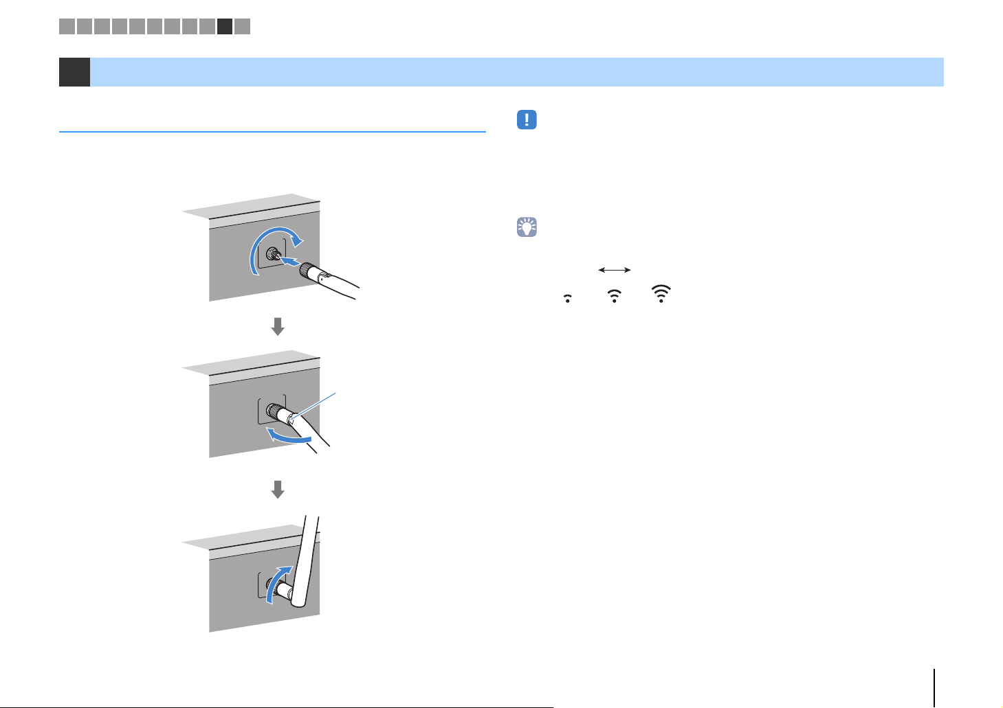
10 Connecting to a network wirelessly (HTR-5067/TSR-5770 only)
Attaching the wireless antenna
Attach the supplied wireless antenna to the unit.
Be sure to turn off the unit before attaching the antenna.
• Do not apply excessive force on the antenna. Doing so may damage the antenna.
• When attaching the antenna, hold the root of the antenna and screw it into the WIRELESS jack tightly.
• The antenna can be bent in only one direction. Check the orientation of the joint and bend the antenna in
the proper direction.
• Do not connect the antenna other than the supplied one.
• When packing the unit, remove the antenna to prevent damage.
WIRELESS
WIRELESS
WIRELESS
• The signal strength indicator on the front display indicates the strength of the wireless signal.
PREPARATIONS ➤ Connecting to a network wirelessly (HTR-5067/TSR-5770 only) En 28
The unit
Wireless router
Mobile device
(such as iPhone)
Internet
Modem
The unit
Mobile device
(such as iPhone)
1 2 3 4 5 6 7 8 9 1011
Selecting the connection method
Select a connection method according to your network environment.
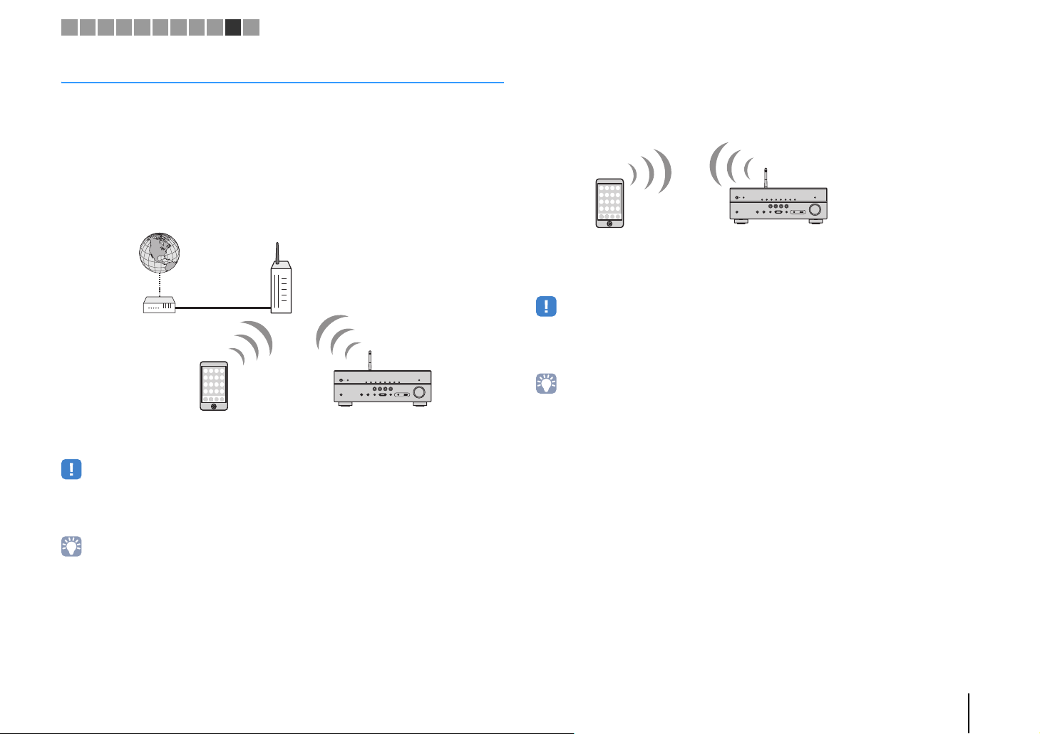
■ Connecting with a wireless router (access point)
Connect the unit to a wireless router (access point).
You can enjoy Internet radio, AirPlay, or music files stored on media servers (PC/NAS)
on the unit.
You can also use the application for smartphone / tablet “AV CONTROLLER” to control
the unit from mobiles devices or enjoy music files stored on mobiles devices on the unit.
For details on connection, see “Connecting the unit to a wireless network” (p.30).
■ Connecting without a wireless router (access point)
Connect a mobile device to the unit directly.
You can use the application for smartphone / tablet “AV CONTROLLER” to control the
unit from mobiles devices or enjoy music files stored on mobiles devices on the unit.
For details on connection, see “Connecting a mobile device to the unit directly
(Wireless Direct)” (p.36).
• You cannot use Wireless Direct simultaneously with the wired LAN connection (p.25) or the wireless LAN
connection (p.28).
• When Wireless Direct is enabled, the unit cannot connect to the Internet. Therefore, you cannot use any
kind of Internet service such as Internet radio.
• For details on “AV CONTROLLER”, visit the Yamaha website.
• You cannot use the wireless LAN connection simultaneously with the wired LAN connection (p.25) or
Wireless Direct (p.36).
• If the unit and the wireless router (access point) are too far apart, the unit may not connect to a wireless
router (access point). In such case, place them close to each other.
• For details on "AV CONTROLLER", visit the Yamaha website.
PREPARATIONS ➤ Connecting to a network wirelessly (HTR-5067/TSR-5770 only) En 29
1
234
5
6
Y
PRESET
TU
G
S
E
RETURN
TO
MENU
POP-U
MENU
D
O
MUTE
DISPLAY
T
S
P
AUXUSB
5
6
ZO
ZO
A
C
S
E
BASS
MODE
N
234
1
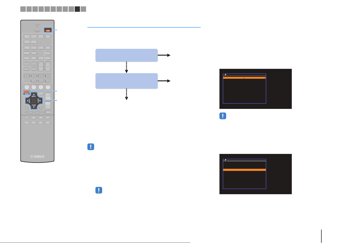
Yes
Do you own iOS devices
(iPhone/iPod touch)?
Yes
A (p.30)
B (p.31)
Does your wireless router
(access point) has a WPS
button?
C (p.32)
No
No
Network Connection
Connection Wireless (Wi-Fi)
: ENTEROK
: RETURNBack
Wireless (Wi-Fi)
: RETURNBack
: ENTEROK
Select a setup method.
WPS Button
Share Wi-Fi Settings(iOS)
PIN Code
Access Point Scan
Manual Setting
1 2 3 4 5 6 7 8 9 1011
TRANSMIT
TRANSMI
SLEEP
LEE
HDMI
2341
5 6
AV
1234
5 6
AUX USB
FM
INFO
INFO
MOVIE MUSIC
MOVIEMUSI
BD
B
DVD
SETUP
RETURN
TOP
MENU
MODE
AM
MEMORY
MEMOR
BASS DIRECT
SCENE
CEN
TV
ENTER
P
NET
PRESET
SUR. DECODE STRAIGHT
UR. DECODESTRAIGHT
NHANCER
ENHANCER
NET
OPTIO
OPTION
VOLUME
VOLUME
DISPLAY
POP-UP
P
MENU
RECEIVER
ZONE A
NE
ZONE B
NE B
TUNING
NIN
DIRECT
RADIO
RADI
MUTE
RECEIVER z RECEIVER z
SETUP
Cursor keys
ENTER
Connecting the unit to a wireless network
There are several methods to connect the unit to a wireless
network.
Select a connection method according to your environment.
■ A: Sharing the iOS device setting
You can easily setup a wireless connection by applying the
connection settings on iOS devices (iPhone/iPod touch).
Before proceeding, confirm that your iOS device is connected to a
wireless router.
• You need iOS device with iOS 5.0 or later. For details on supported devices, see
“Supported devices and file formats” (p.109).
Use the cursor keys (q/w) to select “Network” and
4
press ENTER.
Use the cursor keys (q/w) to select “Network
5
Connection” and press ENTER.
Use the cursor keys (e/r) to select “Wireless
6
(Wi-Fi)” and press ENTER.
• The unit may connect automatically to the access point to which it has
connected previously. In this case, the message indicating the successful
connection will appear. You can ignore this message and proceed to the
next step.
Use the cursor keys (q/w) to select “Share Wi-Fi
7
Settings(iOS)” and press ENTER.
Press RECEIVER z to turn on the unit.
1
Turn on the TV and switch the TV input to display
2
video from the unit (HDMI OUT jack).
• Operations with TV screen are available only when your TV is connected to
the unit via HDMI.
Press SETUP.
3
PREPARATIONS ➤ Connecting to a network wirelessly (HTR-5067/TSR-5770 only) En 30
 Loading...