

Page 1

RX-V4 95
Natural Sound AV Receiver
Ampli-Tuner Audio-V ideo
U C A
OWNER’S MANUAL
MODE D’EMPLOI
Page 2
SAFETY INSTRUCTIONS
CAUTION
RISK OF ELECTRIC SHOCK
DO NOT OPEN
CAUTION: TO REDUCE THE RISK OF
ELECTRIC SHOCK, DO NOT REMOVE
COVER (OR BACK). NO USER-SERVICEABLE
PARTS INSIDE. REFER SERVICING TO
QUALIFIED SERVICE PERSONNEL.
• Explanation of Graphical Symbols
The lightning flash with arrowhead symbol,
within an equilateral triangle, is intended to alert
you to the presence of uninsulated “dangerous
voltage” within the product’s enclosure that may
be of sufficient magnitude to constitute a risk of
electric shock to persons.
The exclamation point within an equilateral
triangle is intended to alert you to the presence
of important operating and maintenance
(servicing) instructions in the literature
accompanying the appliance.
WARNING
TO REDUCE THE RISK OF FIRE OR
ELECTRIC SHOCK, DO NOT EXPOSE THIS
UNIT TO RAIN OR MOISTURE.
1 Read Instructions – All the safety and operating instructions
should be read before the unit is operated.
2 Retain Instructions – The safety and operating instructions
should be retained for future reference.
3 Heed Warnings – All warnings on the unit and in the
operating instructions should be adhered to.
4 Follow Instructions – All operating and other instructions
should be followed.
5 Water and Moisture – The unit should not be used near
water – for example, near a bathtub, washbowl, kitchen
sink, laundry tub, in a wet basement, or near a swimming
pool, etc.
6 Carts and Stands – The unit should be used only with a
cart or stand that is recommended by the
manufacturer.
6A A unit and cart combination should be moved
with care. Quick stops, excessive force, and
uneven surfaces may cause the unit and cart
combination to overturn.
8 Ventilation – The unit should be situated so that its location
or position does not interfere with its proper ventilation. For
example, the unit should not be situated on a bed, sofa,
rug, or similar surface, that may block the ventilation
openings; or placed in a built-in installation, such as a
bookcase or cabinet that may impede the flow of air
through the ventilation openings.
9 Heat – The unit should be situated away from heat sources
such as radiators, stoves, or other appliances that produce
heat.
10 Power Sources – The unit should be connected to a power
supply only of the type described in the operating
instructions or as marked on the unit.
11 Power-Cord Protection – Power-supply cords should be
routed so that they are not likely to be walked on or
pinched by items placed upon or against them, paying
particular attention to cords at plugs, convenience
receptacles, and the point where they exit from the unit.
12 Cleaning – The unit should be cleaned only as
recommended by the manufacturer.
13 Nonuse Periods – The power cord of the unit should be
unplugged from the outlet when left unused for a long
period of time.
14 Object and Liquid Entry – Care should be taken so that
objects do not fall into and liquids are not spilled into the
inside of the unit.
15 Damage Requiring Service – The unit should be serviced
by qualified service personnel when:
A. The power-supply cord or the plug has been
damaged; or
B. Objects have fallen, or liquid has been spilled into the
unit; or
C. The unit has been exposed to rain; or
D. The unit does not appear to operate normally or exhibits
a marked change in performance; or
E. The unit has been dropped, or the cabinet damaged.
16 Servicing – The user should not attempt to service the unit
beyond those means described in the operating
instructions. All other servicing should be referred to
qualified service personnel.
17 Power Lines – An outdoor antenna should be located away
from power lines.
18 Grounding or Polarization – Precautions should be taken
so that the grounding or polarization is not defeated.
7 Wall or Ceiling Mounting – The unit should be mounted to a
wall or ceiling only as recommended by the manufacturer.
2
Page 3
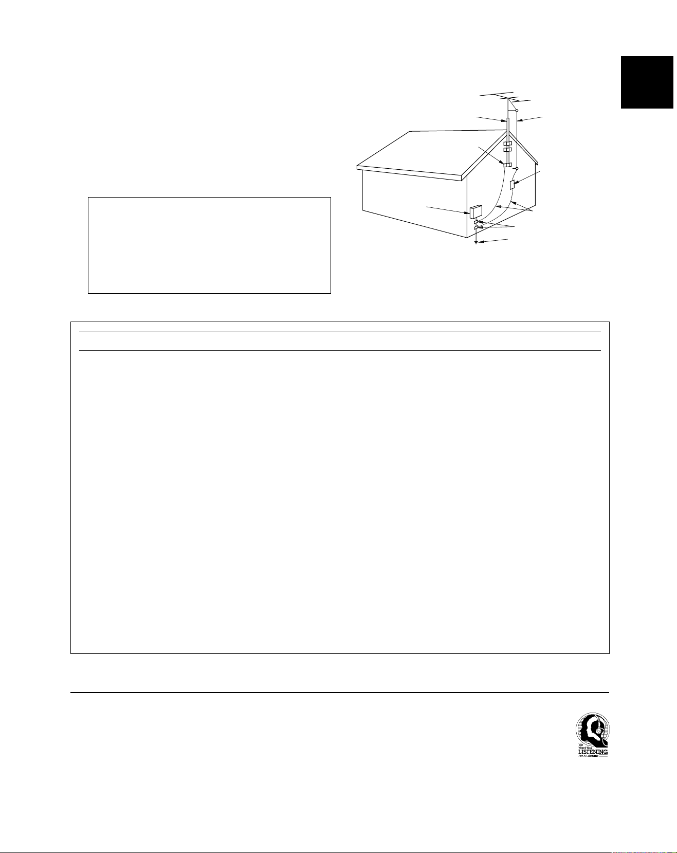
19 For US customers only:
Outdoor Antenna Grounding – If an outside antenna is
connected to this unit, be sure the antenna system is
grounded so as to provide some protection against voltage
surges and built-up static charges. Article 810 of the
National Electrical Code, ANSI/NFPA 70, provides
information with regard to proper grounding of the mast
and supporting structure, grounding of the lead-in wire to
an antenna discharge unit, size of grounding conductors,
location of antenna discharge unit, connection to grounding
electrodes, and requirements for the grounding electrode.
Note to CATV system installer:
This reminder is provided to call the CATV system
installer’s attention to Article 820-40 of the NEC that
provides guidelines for proper grounding and, in
particular, specifies that the cable ground shall be
connected to the grounding system of the building, as
close to the point of cable entry as practical.
FCC INFORMATION (for US customers only)
EXAMPLE OF ANTENNA GROUNDING
MAST
GROUND
CLAMP
ELECTRIC
SERVICE
EQUIPMENT
NEC
– NATIONAL ELECTRICAL CODE
ANTENNA
LEAD IN
WIRE
ANTENNA
DISCHARGE UNIT
(NEC SECTION 810–20)
GROUNDING CONDUCTORS
(NEC SECTION 810–21)
GROUND CLAMPS
POWER SERVICE GROUNDING
ELECTRODE SYSTEM
(NEC ART 250. PART H)
English
1. IMPORTANT NOTICE : DO NOT MODIFY THIS UNIT!
This product, when installed as indicated in the
instructions contained in this manual, meets FCC
requirements. Modifications not expressly approved by
Yamaha may void your authority, granted by the FCC,
to use the product.
2. IMPORTANT : When connecting this product to
accessories and/or another product use only high
quality shielded cables. Cable/s supplied with this
product MUST be used. Follow all installation instructions. Failure to follow instructions could void your FCC
authorization to use this product in the USA.
3. NOTE : This product has been tested and found to
comply with the requirements listed in FCC Regulations, Part 15 for Class “B” digital devices. Compliance
with these requirements provides a reasonable level of
assurance that your use of this product in a residential
environment will not result in harmful interference with
other electronic devices.
This equipment generates/uses radio frequencies and,
if not installed and used according to the instructions
found in the users manual, may cause interference
harmful to the operation of other electronic devices.
Compliance with FCC regulations does not guarantee
that interference will not occur in all installations. If this
product is found to be the source of interference, which
can be determined by turning the unit “OFF” and “ON”,
please try to eliminate the problem by using one of the
following measures:
Relocate either this product or the device that is being
affected by the interference.
Utilize power outlets that are on different branch (circuit
breaker or fuse) circuits or install AC line filter/s.
In the case of radio or TV interference, relocate/reorient
the antenna. If the antenna lead-in is 300 ohm ribbon
lead, change the lead-in to coaxial type cable.
If these corrective measures do not produce satisfactory results, please contact the local retailer authorized
to distribute this type of product. If you can not locate
the appropriate retailer, please contact Yamaha
Electronics Corp., U.S.A. 6660 Orangethorpe Ave,
Buena Park, CA 90620.
The above statements apply ONLY to those products
distributed by Yamaha Corporation of America or its
subsidiaries.
We Want You Listening For A Lifetime
YAMAHA and the Electronic Industries Association’s Consumer
Electronics Group want you to get the most out of your
equipment by playing it at a safe level. One that lets the sound
come through loud and clear without annoying blaring or
distortion – and, most importantly, without affecting your
sensitive hearing.
Since hearing damage from loud sounds is often
undetectable until it is too late, YAMAHA and the
Electronic Industries Association’s Consumer
Electronics Group recommend you to avoid
prolonged exposure from excessive volume levels.
3
Page 4

SUPPLIED ACCESSORIES
ACCESSOIRES FOURNIS
• After unpacking, check that the following parts are included.
• Après le déballage, vérifier que les pièces suivantes sont incluses.
• Indoor FM Antenna
• Antenne FM intérieure
• AM Loop Antenna
• Cadre-antenne AM
• Antenna adapter
(U.S.A. and Canada models only)
• Adaptateur d’antenne
(Modèles pour les Etats-Unis et le
Canada seulement)
• Remote control transmitter
• Télécommande
• Batteries (size AAA, R6, UM-4)
• Piles (taille AAA, R6, UM-4)
4
Page 5

FEATURES
English
● 5-Channel Power Amplification
Minimum RMS Output Power
<0.04% THD, 20 Hz – 20 kHz>
Main: 60 W + 60 W (8 Ω)
Center:60 W (8 Ω)
Rear: 60 W + 60 W (8 Ω)
<0.07% THD, 1 kHz>
Main: 70 W + 70 W (8 Ω)
Center:70 W (8 Ω)
Rear: 70 W + 70 W (8 Ω)
● Digital Sound Field Processor
● Dolby Digital Decoder
● Dolby Pro Logic Surround Decoder
● CINEMA DSP: Theater-like Sound
Experience by the Combination of Dolby
Surround and YAMAHA DSP Technology
● 6-Channel External Decoder Input for DTS
and other future formats
● Automatic Input Balance Control for
Dolby Pro Logic Surround
● Test Tone Generator for Easier Speaker
Balance Adjustment
● Speaker Output Mode Changing
Capability
● 40-Station Random Access Preset Tuning
● Automatic Preset Tuning
● Preset Station Shifting Capability
(Preset Editing)
● Video Signal Input/Output Capability
● SLEEP Timer
● Universal Remote Control
Transmitter with Preset Manufacturer
Codes
CONTENTS
SUPPLIED ACCESSORIES...........................................4
FEA TURES .................................................................... 5
CAUTION ....................................................................... 6
●Introduction
FEATURES OF SOUND EFFECTS ............................... 7
CONTROLS AND THEIR FUNCTIONS......................... 9
●Preparation
SPEAKER SETUP ....................................................... 14
CONNECTIONS........................................................... 16
ADJUSTMENTS
BEFORE USING THIS UNIT .................................. 23
●Basic Operation
BASIC OPERATIONS .................................................. 28
TUNING OPERATIONS ............................................... 32
SETTING THE SLEEP TIMER..................................... 37
●Information about DSP
USING THE DIGITAL SOUND FIELD
PROCESSOR (DSP) .............................................. 38
●Advanced Information
ADJUSTMENTS
IN THE “SET MENU” MODE...................................44
●Remote Control Transmitter
REMOTE CONTROL TRANSMITTER......................... 46
SETUP CODES ...........................................................53
TROUBLESHOOTING ................................................. 54
SPECIFICA TIONS ....................................................... 57
LIST OF MANUFACTURER’S CODES...................... 113
5
Page 6

CAUTION: READ THIS BEFORE OPERATING YOUR UNIT.
1. To assure the finest performance, please read this manual
carefully. Keep it in a safe place for future reference.
2. Install this unit in a cool, dry, clean place – away from
windows, heat sources, sources of excessive vibration,
dust, moisture and cold. Avoid sources of humming
(transformers, motors). To prevent fire or electrical shock,
do not expose the unit to rain or water.
3. Never open the cabinet. If something drops into the set,
contact your dealer.
4. Do not use force on switches, controls or connection wires.
When moving the unit, first disconnect the power plug and
the wires connected to other equipment. Never pull the
wires themselves.
5. The openings on the unit cover assure proper ventilation of
the unit. If these openings are obstructed, the temperature
inside the unit will rise rapidly. Therefore, avoid placing
objects against these openings, and install the unit in a
well-ventilated area to prevent fire and damage.
<Singapore model only>
Be sure to allow a space of at least 20 cm behind, 20 cm
on the both sides and 30 cm above the top panel of the unit
to prevent fire and damage.
6. The voltage used must be the same as that specified on
this unit. Using this unit with a higher voltage than
specified is dangerous and may result in fire or other
accidents. YAMAHA will not be held responsible for any
damage resulting from use of this unit with a voltage other
than specified.
7. Digital signals generated by this unit may interfere with
other equipment such as tuners, receivers or TVs. Move
this unit farther away from such equipment if interference is
observed.
8. Always set the VOLUME control to “
audio source play. Increase the volume gradually to an
appropriate level after playback has been started.
9. Do not attempt to clean the unit with chemical solvents; this
might damage the finish. Use a clean, dry cloth.
10. Be sure to read the “TROUBLESHOOTING” section
regarding common operating errors before concluding that
the unit is faulty.
11. When not planning to use this unit for long periods of time
(ie., vacation, etc.), disconnect the AC power plug from the
wall outlet.
12. To prevent lightning damage, disconnect the AC power
plug and disconnect the antenna cable when there is an
electrical storm.
13. Grounding or polarization – Precautions should be taken so
that the grounding or polarization of an appliance is not
defeated.
14. AC outlet
Do not connect audio equipment to the AC outlet on the
rear panel if that equipment requires more power than the
outlet is rated to provide.
15. Voltage Selector (China and General Models only)
The voltage selector on the rear panel of this unit must
be set for your local main voltage BEFORE plugging
into the AC main supply.
Voltages are 110/120/220/240 V AC, 50/60 Hz.
” before starting the
This unit is not disconnected from the AC power source as
long as it is connected to the wall outlet, even if this unit
itself is turned off. This state is called the standby mode. In
this state, this unit is designed to consume a very small
quantity of power.
FREQUENCY STEP switch
(China and General Models only)
Because the interstation frequency spacing differs in
different areas, set the FREQUENCY STEP switch (located
at the rear) according to the frequency spacing in your area.
Before setting this switch, disconnect the AC power plug of
this unit from the AC outlet.
IMPORTANT
Please record the serial number of this unit in the space
below.
MODEL:
Serial No.:
The serial number is located on the rear of the unit.
Retain this Owner’s Manual in a safe place for future
reference.
WARNING
TO REDUCE THE RISK OF FIRE OR ELECTRIC SHOCK,
DO NOT EXPOSE THIS UNIT TO RAIN OR MOISTURE.
FOR CANADIAN CUSTOMERS
To prevent electric shock, match wide blade of plug to wide
slot and fully insert.
This Class B digital apparatus complies with Canadian
ICES-003.
6
Page 7

Introduction
English
FEATURES OF SOUND EFFECTS
Welcome to the exciting world of digital home entertainment.
This unit is one of the most complete and advanced AV
receivers available. Some of the more advanced features may
not be familiar to you, but they are easy to use. State-of-the-art
technologies such as Dolby Digital and Digital Theater Systems
(DTS) may be new to your home, but you have probably
experienced the amazing realism they bring to feature films in
theaters around the world.
Digital Sound Field Processing
What is it that makes live music so good? Today’s advanced
sound reproduction technology lets you get extremely close to
the sound of a live performance, but the chances are that you’ll
still notice something missing — the acoustic environment of
the live concert hall. Extensive research into the exact nature
of the sonic reflections that create the ambience of a large hall
has made it possible for YAMAHA engineers to bring you this
same sound to your listening room, so you’ll feel all the sound
of a live concert.
Dolby Pro Logic Surround
Dolby Pro Logic Surround has been used in movie theaters
since the mid-seventies. It has also been available in home
entertainment systems since the late eighties and continues to
be a popular format for home theater systems. It uses four
discrete channels and five speakers to reproduce realistic and
dynamic sound effects: two main channels (left and right), a
center channel for dialog, and a rear channel for special sound
effects. The rear channel reproduces sound within a narrow
frequency range.
To make the listening experience even more enjoyable, this unit
includes a number of exclusive, digitally created listening
environments known as digital sound fields. Choosing a sound
field program is like transporting yourself to such venues as an
outdoor arena, a European church, or a cozy jazz club. Take
some time now to read more about these features and enjoy
the new experiences this unit brings to your home theater.
Furthermore, our technicians, armed with sophisticated
measuring equipment, have even made it possible to capture
the acoustics of a variety of actual concert halls, theaters, etc.
from around the world, to allow you to accurately re-create any
one of these live performance environments, all in your own
home.
Most video tapes and laser discs include Dolby Pro Logic
Surround encoding, as do many TV and cable broadcasts. The
Dolby Pro Logic Surround decoder built into this unit employs a
digital signal processing system that stabilizes each channel for
even more accurate sound positioning than is available with
standard analog processors.
Dolby Digital
The built-in Dolby Digital decoder leads you into a totally new
sound experience.
Dolby Digital is a new generation of multi-channel digital audio
technology, or the newest spatial sound processing format
developed for 35 mm-film movies by employing a new kind of
low bit-rate audio coding.
Dolby Digital is a digital surround sound system that provides
completely independent multi-channel audio to listeners. In
multi-channel form, Dolby Digital provides 5 full-range channels
in what is sometimes referred to as a “3/2” configuration: three
front channels (left, center and right), plus two surround
channels. A sixth bass-only effect channel is also provided for
output of LFE (low frequency effect), or low bass effects that
are independent of other channels. This channel is counted as
0.1, thus giving rise to the term 5.1 channels in total.
Compared to Dolby Pro Logic, which is referred to a “3/1”
system (left front, center, right front and just one surround
channel), Dolby Digital features two surround channels, called
stereo or split surrounds, each offering the same full-range
fidelity as the three front channels.
Sound of wide dynamic range reproduced by the 5 full-range
channels provides listeners with excitement that has never
been experienced before. Precise sound orientation by
discrete digital sound processing expands the realism that the
original movie possesses.
LD and DVD are home audio/video program source that could
benefit from Dolby Digital. In the near future, Dolby Digital will
also be applied to DBS, CATV and HDTV. The ongoing release
of Dolby Stereo Digital theatrical films now underway will
provide an immediate source of Dolby Digital encoded video
software.
7
Page 8

Manufactured under license from Dolby Laboratories Licensing
Corporation. “DOLBY”, “PRO LOGIC”, and the double-D symbol
are trademarks of Dolby Laboratories Licensing Corporation.
Copyright 1992 Dolby Laboratories, Inc. All rights reserved.
CINEMA DSP: Dolby Surround + DSP
The following original functions make the surround-sound effect
of Dolby Digital become the most suitable for your audio
system and the listening conditions.
The Dolby Surround sound system shows its full ability in a
large movie theater, because movie sounds are originally
designed to be reproduced in a large movie theater using many
speakers. It is difficult to create a sound environment similar to
that of a movie theater in your listening room, because the
room size, materials of inside walls, the number of speakers,
etc. of your listening room are very different from those of a
movie theater.
Dolby Pro Logic + 2 Digital Sound Fields
Digital sound fields are created on the presence side and the
rear surround side of the Dolby Pro Logic Surround-decoded
sound field, respectively. They create a wide acoustic
environment and emphasize the surround effect in the room,
letting you feel as much presence as if you are watching a
movie in a popular Dolby Stereo theater.
This combination is available when the DOLBY PRO LOGIC
ENHANCED/DOLBY DIGITAL ENHANCED, 70 mm MOVIE
THEATER/DIGITAL MOVIE THEA TER or TV SPOR TS sound
field program is selected, and the input signal of source is
analog, PCM audio or encoded with Dolby Digital sound in
2-channel.
YAMAHA DSP technology made it possible to present you with
nearly the same sound experience as that of a large movie
theater in your listening room by compensating for the lack of
presence and dynamics in your listening room with its original
digital sound fields combined with the Dolby Surround sound
system.
CINEMA DSP
The YAMAHA “CINEMA DSP” logo indicates those programs
that are created by the combination of Dolby Surround and
YAMAHA DSP technology.
Dolby Digital + 3 Digital Sound Fields
Digital sound fields are created on the presence side and the
independent left and right surround sides of the Dolby Digitaldecoded sound field, respectively. They create a wide
acoustic environment and strong surround effect in the room
without losing high-channel separation. With the wide
dynamic range of Dolby Digital sound, this sound field
combination lets you feel as if you are watching a movie in the
newest Dolby Stereo Digital theater. This will be the most
ideal home theater sound at the present time.
This combination is available when the DOLBY PRO LOGIC
ENHANCED/DOLBY DIGITAL ENHANCED, 70 mm MOVIE
THEATER/DIGITAL MOVIE THEA TER or TV SPORTS sound
field program is selected, and the input signal of source is
encoded with Dolby Digital sound (except in 2-channel).
8
Page 9

CONTROLS AND THEIR FUNCTIONS
FRONT PANEL
English
1 STANDBY/ON
Press this switch to turn on the power to this unit. Press it
again to set this unit to the standby mode.
Standby mode
In this state, this unit consumes a very small quantity of
power to receive infrared-signals from the remote control
transmitter.
2 Remote control sensor
This receives signals from the remote control transmitter.
3 Display
This shows various information. (Refer to page 11 for details.)
4 MEMORY (MAN’L/AUTO FM)
Press this button to store the broadcasting stations.
When this button is pressed and held for more than three
seconds, the automatic preset tuning begins.
5 EDIT
This button is used to exchange the assignment of two preset
stations with each other.
6 TUNING MODE (AUTO/MAN’L MONO)
Press this button to switch the tuning mode to automatic or
manual. To select the automatic tuning mode, press this button
so that the “AUTO TUNING” indicator lights up on the display.
To select the manual tuning mode, press this button so that the
“AUTO TUNING” indicator goes off.
7 FM/AM
Press this button to switch the reception band to FM or AM.
8 TUNING UP/DOWN
This button is used for tuning. Press the UP side to tune in to
higher frequencies, and press the DOWN side to tune in to
lower frequencies.
9 TAPE/MD MON / EXT. DECODER
Press this button to play a tape or an MD. The “TAPE/MD
MON” indicator lights up on the display.
When you press the button next, the “TAPE/MD MON” indicator
goes off, “EXT. DECDR” appears on the display and you can
play the signal connected to the EXTERNAL DECODER
INPUT terminals.
0 INPUT
Turn this selector to select the program source (VCR, VIDEO
AUX, TV/DBS, DVD/LD, CD, TUNER, PHONO) to listen to or
watch.
The name of the selected program source appears on the
display.
9
Page 10

q INPUT MODE
This button switches the DVD/LD and TV/DBS input signal
mode (AUTO/ANALOG).
w VOLUME
This control is used to raise or lower the volume level.
i BALANCE
This control is only effective for the sound from the main
speakers.
Turn the control to adjust the balance of the output volume to
the left and right speakers to compensate for sound imbalance
caused by the speaker location or listening room conditions.
e PHONES jack
When you use headphones, connect the headphones to the
PHONES jack. You can listen to the sound to be output from
the main speakers through the headphones.
When using headphones only , set both SPEAKERS A and B to
the OFF position and switch off the digital sound field processor
(so that no DSP program name appears on the display) by
pressing EFFECT.
r SPEAKERS
Set A or B (or both A and B) to the ON position for the main
speaker system (connected to this unit) that you want to use.
Set the button(s) for the main speaker system you don’t want to
use to the OFF position.
t A/B/C/D/E
Press this button to select one of a group (A to E) of preset
stations.
y Preset station number selector
Each of these buttons selects a preset station number
(1 to 8).
u Tone controls
These controls are only effective for the sound from the main
speakers.
BASS
Use this control to increase or decrease the low-frequency
response. The “0” position produces flat response.
TREBLE
Use this control to increase or decrease the high-frequency
response. The “0” position produces flat response.
o TIME/LEVEL
Press this button to select the item in the TIME/LEVEL mode.
p +/–
These buttons are used to adjust the settings of the SET MENU
mode and the TIME/LEVEL mode. In the TIME/LEVEL mode,
press + to increase the delay time or speaker output level.
Press – to decrease the delay time or speaker output level.
a SET MENU
Press this button to select functions in the SET MENU mode.
s PROGRAM selector
Press
The name of the selected program appears on the display.
or to select the DSP program.
d EFFECT
This button switches on and off the output from the center and
rear speakers so that the sound becomes the normal
2-channel.
* Even if the output from the center and rear speakers is off,
when the Dolby Digital is decoded, the signals on all
channels are distributed to the main channels and output
from the main speakers.
f VIDEO AUX terminals
Connect an auxiliary video or audio input source unit such as a
camcorder to these terminals. The source connected to these
terminals can be selected by INPUT.
10
Page 11

DISPLAY PANEL
English
1 Multi-information display
This displays various information, for example the station
frequency, preset station number and name of the selected
program source.
2 MEMORY indicator
When MEMORY is pressed, this indicator flashes for about five
seconds. During this period, the displayed station can be
stored in the memory.
3 AUTO TUNING indicator
This lights up when the unit is in the automatic tuning mode.
4 TAPE/MD MON indicator
This lights up when the tape deck (or MD recorder, etc.) is
selected as the program source by pressing T APE/MD MON /
EXT . DECODER on the front panel or TAPE/MD on the remote
control transmitter.
5 STEREO indicator
This lights up when an FM stereo broadcast with sufficient
signal strength is being received.
Signal-level meter
6
This indicates the signal level of the station being received.
If multipath interference is detected, the indication decreases.
7 , and indicators
“
on and the signal of the selected source encoded in Dolby
Digital sound is not in 2-channel. “
built-in digital sound field processor is on, and “
lights up when the built-in Dolby Pro Logic Surround decoder is
on. Depending on the selected DSP program, both “
and “
” lights up when the built-in Dolby Digital decoder is
” lights up when the
”
”, or both “ ” and “ ” will light up.
8 SLEEP indicator
This lights up while the built-in SLEEP timer is functioning.
”
11
Page 12
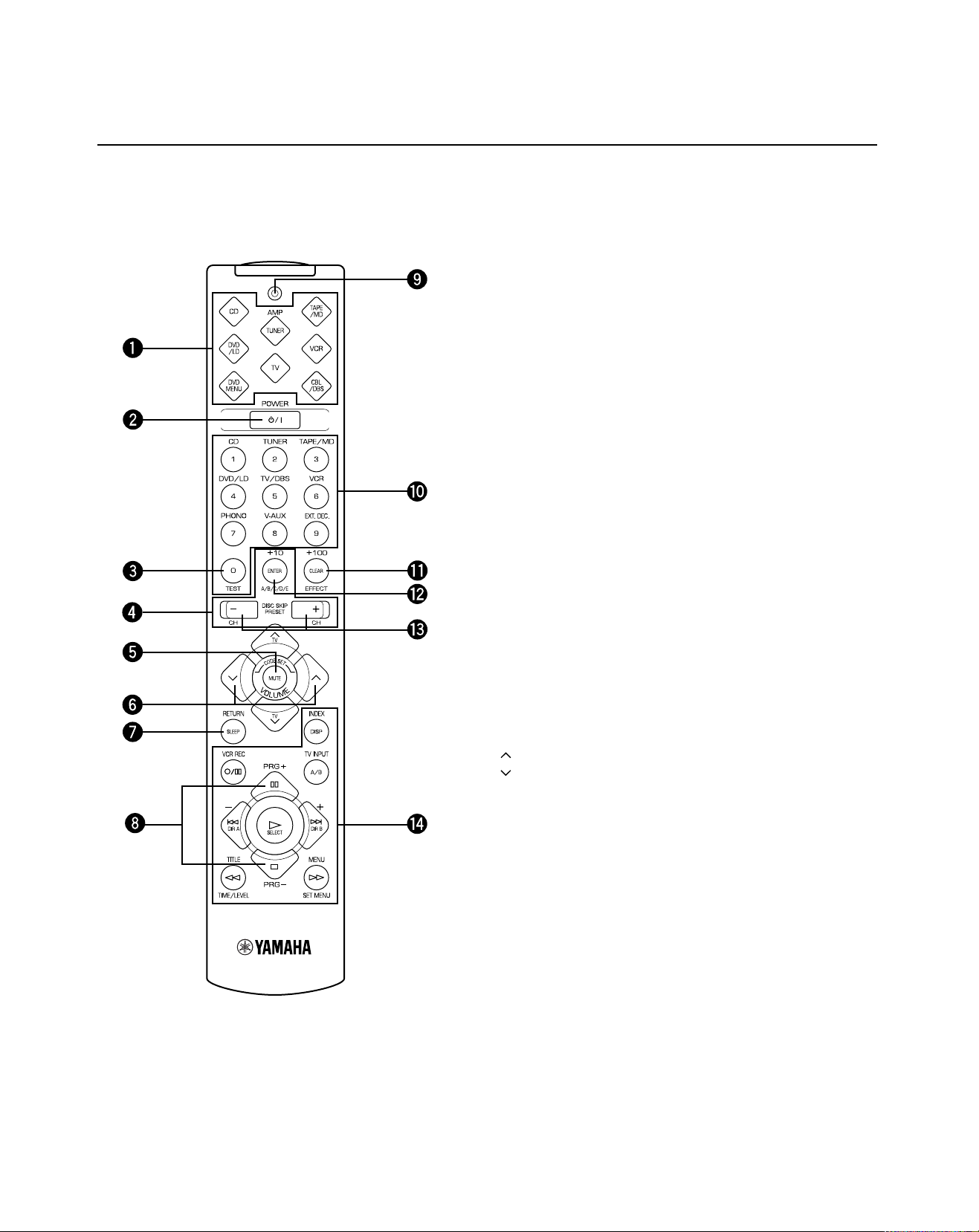
REMOTE CONTROL TRANSMITTER
See “REMOTE CONTROL TRANSMITTER” on page 46 for full details.
1 Component selector
Press the button for the component you want to control with the
remote control transmitter. (The proper code must be set for
your component. See “SETUP CODES” on page 53.)
When the component selector has been pressed, the remote
control transmitter is set to operate that component.
2 POWER
When you have preset the code for a YAMAHA component, this
button switches between the power on and standby mode.
When you have preset the code for another manufacturer’s
component, this button turns on that component if it has a
remote control transmitter with a power button.
* It only functions when AMP<TUNER>, TAPE/MD, CD, DVD/LD or
3 TEST
Press this button to output the test tone for each speaker.
* It only functions when AMP<TUNER> on the component selector
DVD MENU on the component selector has been pressed.
has been pressed.
4 A/B/C/D/E, PRESET +/–
These buttons are used to select a preset station.
* They only function when AMP<TUNER> on the component selector
has been pressed.
5 MUTE
Press this button to mute the sound.
6 VOLUME
These buttons are used to adjust the volume.
: Turns up the volume.
: Turns down the volume.
7 SLEEP
This button is used to set the SLEEP timer.
8 PRG+, PRG–
These buttons are used to select a DSP program.
* They only function when AMP<TUNER> on the component selector
has been pressed.
9 Indicator
This flashes in red when a button on the remote control
transmitter is pressed. When it flashes rapidly several times,
press the selected button again.
12
0 Input selector (1 to 9)
1) These buttons are used to select the program source to be
played.
* They only function when AMP<TUNER>, TAPE/MD, CD or
DVD/LD on the component selector has been pressed.
2) These buttons are used to select the menu or channel.
* They only function when DVD MENU, VCR, CBL/DBS or TV on
the component selector has been pressed.
1)
/Numeric buttons
2)
Page 13

English
q EFFECT
1)
/CLEAR2)/+100
3)
1) This button is used to switch the DSP program on or off.
* It only functions when AMP<TUNER>, TAPE/MD, CD, D VD/LD,
VCR or TV on the component selector has been pressed.
2) This button is used to clear the settings.
* It only functions when DVD MENU on the component selector
has been pressed.
3) This button is used to select the channel.
* It only functions when CBL/DBS on the component selector has
been pressed.
1)
w ENTER
/+10
2)
1) This button is used to enter the channel.
* It only functions when VCR, CBL/DBS or TV on the component
selector has been pressed.
2) This button is used to select the menu.
* It only functions when DVD MENU on the component selector
has been pressed.
e DISC SKIP +/–
1)
/CH +/–
2)
1) These buttons are used to skip to the next or previous disc.
* They only function when CD, DVD/LD or DVD MENU on the
component selector has been pressed.
2) These buttons are used to select the next or previous
channel.
* They only function when VCR, CBL/DBS or TV on the
component selector has been pressed.
r Operation buttons
1)
/Setup buttons
2)
1) These buttons function as play, stop, skip, etc. for
operating the component.
* They only function when TAPE/MD, CD, D VD/LD, VCR or TV on
the component selector has been pressed.
2) These buttons are for adjusting various settings.
* They only function when AMP<TUNER>, DVD MENU or CBL/
DBS on the component selector has been pressed.
13
Page 14

SPEAKERS TO BE USED
SPEAKER SETUP
This unit is designed to provide the best sound-field quality with
a 5-speaker configuration, using main speakers, rear speakers
and a center speaker.
The main speakers are used for the main source sound plus
the effect sounds. They will probably be the speakers from
your present stereo system. The rear speakers are used for
the effect and surround sounds, and the center speaker is for
the center sounds (dialog, vocals, etc.). If for some reason it is
not practical to use a center speaker, you can do without it.
Best results, however, are obtained with the full system.
The main speakers should be high-performance models and
have enough power-handling capacity to accept the maximum
output of your audio system.
The other speakers do not have to be equal to the main
speakers. For precise sound localization, however, it is ideal to
use high-performance models that can reproduce sounds over
the full-range for the center speaker and the rear speakers.
SPEAKER CONFIGURATION
5-Speaker Configuration
Use of a subwoofer expands your sound field
It is also possible to further expand your system with the
addition of a subwoofer and amplifier. The use of a subwoofer
is effective not only for reinforcing bass frequencies from any or
all channels, but also for reproducing the LFE (low frequency
effect) sound with high fidelity when playing back a source that
is Dolby Digital-decoded. You may wish to choose the
convenience of a YAMAHA Active Servo Processing Subwoofer
System, which has its own built-in power amplifier.
4-Speaker Configuration
This configuration is the most effective and recommended one.
When playing back a source using the DSP program,
DOLBY PRO LOGIC/DOLBY DIGITAL, DOLBY PRO LOGIC
ENHANCED/DOLBY DIGITAL ENHANCED, 70 mm MOVIE
THEATER/DIGITAL MOVIE THEATER, MONO MOVIE or TV
SPORTS, or when playing back a source which contains
center-channel signals (dialog, vocals, etc.) using any DSP
program that is Dolby Digital-decoded, conversations will be
output from the center speaker and the ambience will be
excellent.
Note: Set the CNTR (CENTER SPEAKER) mode to the
“LARGE” or “SMALL” position. (See page 23 for
details.)
Main L Center Main R
Dialog
Surround sound
The center speaker is not used in this configuration. When
playing back a source using the DSP program, DOLBY PRO
LOGIC/DOLBY DIGITAL, DOLBY PRO LOGIC ENHANCED/
DOLBY DIGITAL ENHANCED, 70 mm MOVIE THEATER/
DIGITAL MOVIE THEATER, MONO MOVIE or TV SPORTS, or
when playing back a source which contains center-channel
signals (dialog, vocals, etc.) using any DSP program that is
Dolby Digital-decoded, the center sound is output from the left
and the right main speakers. However, the sound effect of
other programs will be the same as that of the 5-speaker
configuration.
Note: Be sure to set the CNTR (CENTER SPEAKER) mode to
the “NONE” position. (See page 23 for details.)
Main L Main R
Dialog
Surround sound
14
Rear L Rear R
Rear L Rear R
Page 15
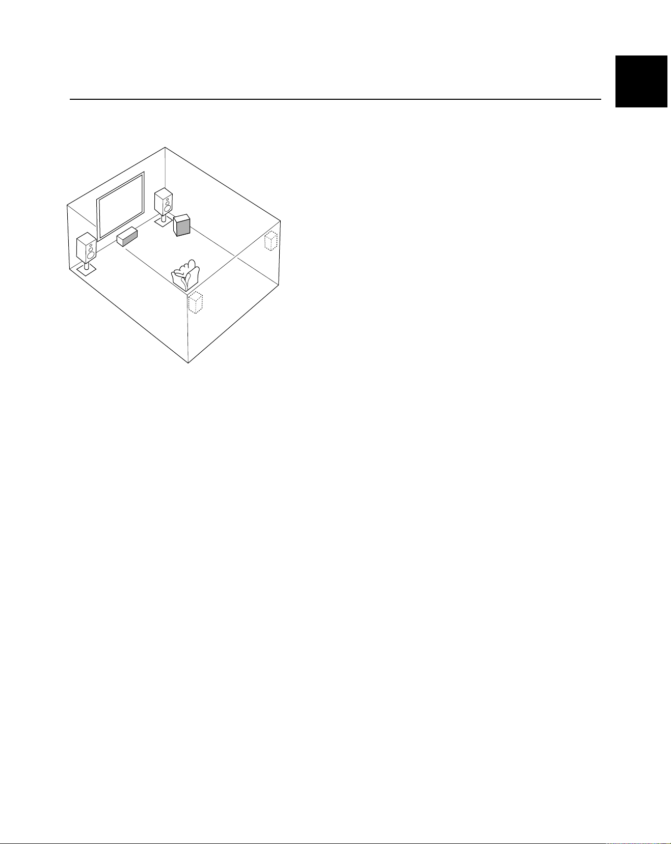
SPEAKER PLACEMENT
Refer to the following diagram when you place the speakers.
Main
speaker (R)
Subwoofer
Center speaker
Main
speaker (L)
Rear
speaker
(L)
Rear
speaker (R)
English
Main: The position of your present stereo speaker
system.
Rear: Behind your listening position, facing slightly
inward. Nearly 1.8 m (approx. 6 feet) up from the
floor.
Center: Precisely between the main speakers. (To avoid
interference with TV sets, use a magnetically
shielded speaker.)
Subwoofer: The position of the subwoofer is not as critical,
because low bass tones are not highly directional.
15
Page 16
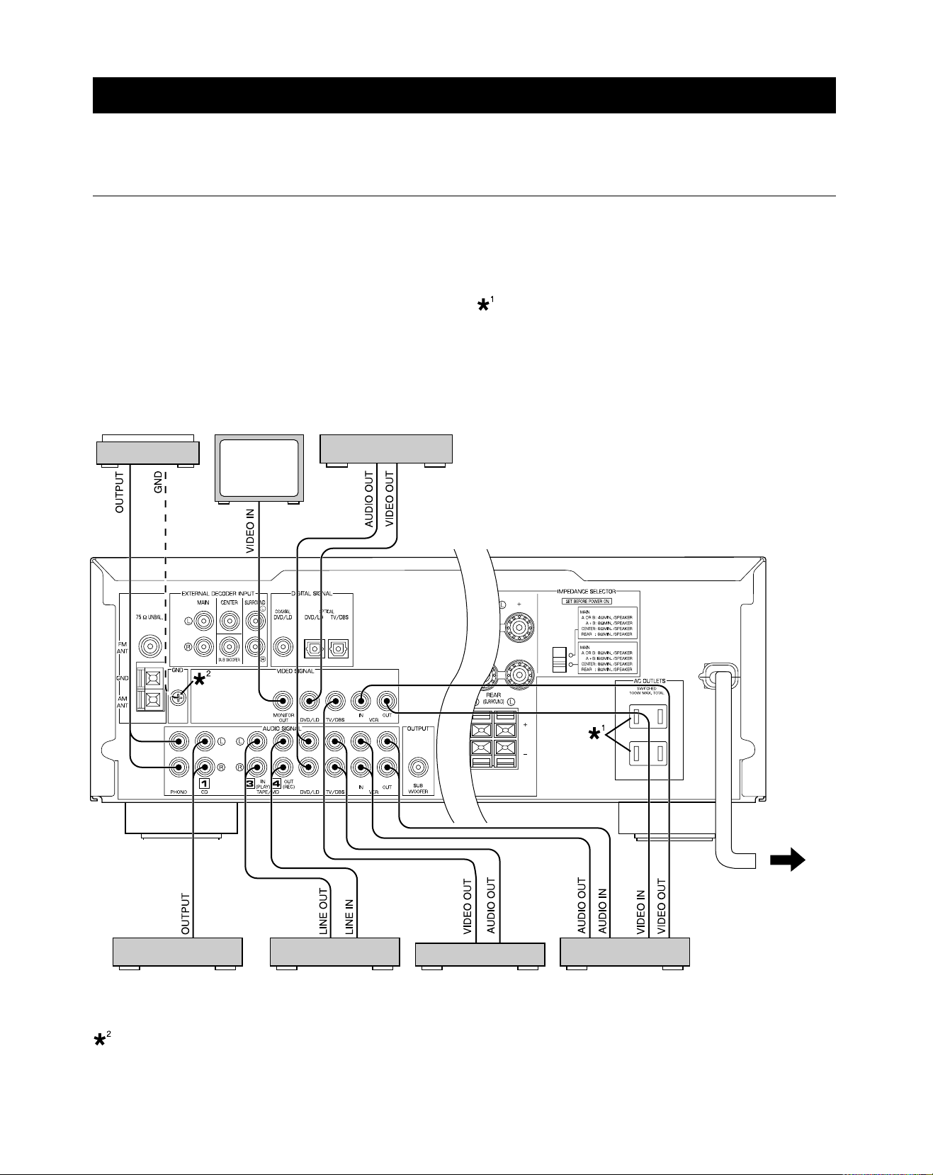
CONNECTIONS
Never plug in this unit and other components until all connections have been completed.
CONNECTIONS WITH OTHER COMPONENTS
When making connections between this unit and other components, be sure all connections are made correctly, that is to say L
(left) to L, R (right) to R, “+” to “+” and “–” to “–”. Also, refer to the owner’s manual for each component to be connected to this unit.
* If you have YAMAHA components numbered as !, #, $, etc. on the rear panel, connections can be made easily by making sure
to connect the output (or input) terminals of each component to the same-numbered terminals of this unit.
SWITCHED AC OUTLET(S)
U.S.A., Canada, Singapore, China and General models
........................................................... 2 SWITCHED OUTLETS
Australia model .....................................1 SWITCHED OUTLET
Use these to connect the power cords from your components to
Turntable Monitor TV
DVD player,
LD player, etc.
this unit.
The power to the SWITCHED AC OUTLET(S) is controlled by
this unit’s STANDBY/ON or the provided remote control
transmitter’s POWER. These outlets will supply power to any
component whenever this unit is turned on.
The maximum power (total power consumption of components)
that can be connected to the SWITCHED AC OUTLET(S) is
100 watts.
(U.S.A. model)
T o AC outlet
CD player Tape deck,
MD recorder, etc.
TV/DBS tuner
VCR
(Video cassette recorder)
GND terminal (for turntable use)
Connecting the ground (earth) wire of the turntable to the GND terminal will normally minimize hum, but in some cases, better
results may be obtained with the ground wire disconnected.
16
Page 17
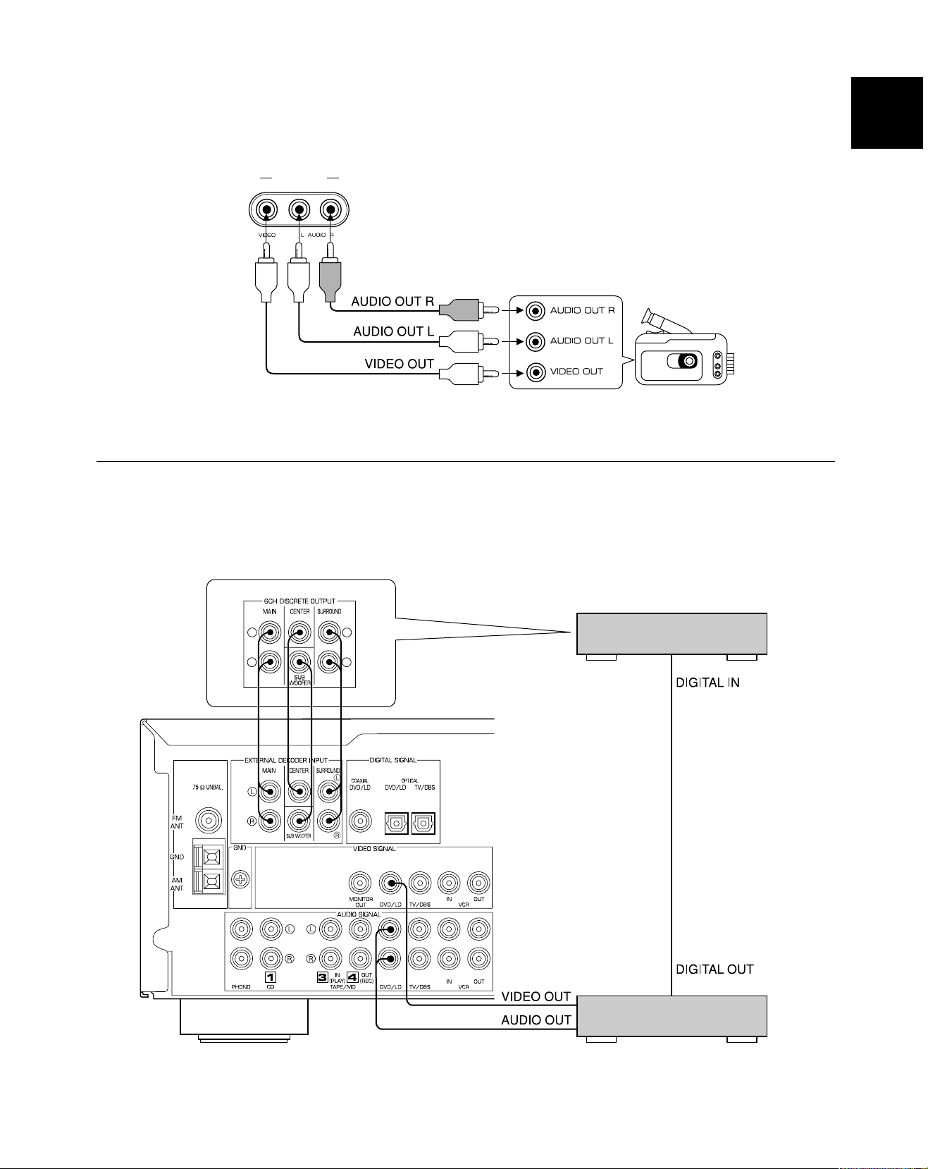
CONNECTING TO VIDEO AUX TERMINALS (ON THE FRONT PANEL)
These terminals are used to connect any video input source, such as a camcorder, to this unit.
VIDEO AUX
CONNECTING TO AN EXTERNAL DECODER
English
Camcorder
When using the DTS or other decoder with 6-channel discrete outputs, connect the 6CH DISCRETE OUTPUT terminals of the
decoder to the EXTERNAL DECODER INPUT terminals of this unit.
DTS or other decoder with 6-channel
discrete outputs
L
R
L
R
(U.S.A. model)
DVD player, LD player or other
unit with digital outputs
17
Page 18

CONNECTING TO DIGITAL (COAXIAL AND/OR OPTICAL) TERMINALS
If your DVD (LD) player, TV/DBS tuner, etc. are equipped with
coaxial or optical digital audio signal output terminals, they can
be connected to this unit’s COAXIAL and/or OPTICAL digital
signal input terminals.
To make a connection between optical digital audio signal
terminals, remove the cover from each terminal, and then
connect them by using a commercially available optical fiber
cable that conforms to EIAJ standards. Other cables might not
function correctly.
Even if you connect an audio/video unit to the COAXIAL (or
OPTICAL) terminal of this unit, you must keep the unit
connected with the same named analog audio signal terminals
of this unit, because a digital signal cannot be recorded by a
tape deck, MD recorder or VCR connected to this unit. You can
easily switch the selection of input signals between “digital” and
“analog”. (See page 30 for details.)
DVD or LD player TV/DBS tuner
Notes
• When connecting an audio/video unit to both the digital and
analog terminals of this unit, make sure to connect between
terminals of the same name.
• Be sure to attach the covers when the OPTICAL terminals
are not being used in order to protect them from dust.
• The input signal from the DVD/LD input terminals is selected
in the following order of priority with the input mode set to the
AUTO position:
1 COAXIAL terminal
2 OPTICAL terminal
3 Analog terminal
• All digital audio signal input terminals are applicable to
sampling frequencies of 32 kHz, 44.1 kHz and 48 kHz.
• If your LD player has Dolby Digital RF signal output terminal
and not digital signal output, use the RF demodulator
(separate purchase).
(U.S.A. model)
18
Page 19

CONNECTING SPEAKERS
Main speakers A Main speakers B
English
Right
Subwoofer system
OUTPUT
SUB
WOOFER
Left
SPEAKERS
R
CENTER
Center speaker
Right Left
REAR
(SURROUND)
R
L
L
MAIN
Left
Rear speakers
Right
Note
Use speakers with the specified impedance shown on the
rear panel of this unit.
Main speaker connections
One or two speaker systems can be connected to this unit. If
you use only one speaker system, connect it to either of the
SPEAKERS A or B terminals.
Rear speaker connections
A rear speaker system can be connected to this unit. Place
them to the rear of your listening position.
Center speaker connection
A center speaker can be connected to this unit. Place it on or
under the TV.
Subwoofer connection
You may wish to add a subwoofer to reinforce low frequencies
or to output low bass sound from the subwoofer channel.
If you have a subwoofer with built-in amplifier, including the
YAMAHA Active Servo Processing Subwoofer System, connect
the SUBWOOFER OUTPUT terminal of this unit to the input
terminal of the subwoofer system.
If you have a separate amplifier and subwoofer, connect the
SUBWOOFER OUTPUT terminal of this unit to the input
terminal of the subwoofer amplifier, and then connect the
speaker terminals of the subwoofer amplifier to the subwoofer.
When the input signals to this unit are for normal 2-channel
stereo, this terminal outputs only frequencies below 90 Hz from
the main and center channels. When discrete signals are input
to this unit and are selected as the input source, this terminal
outputs signals from the subwoofer channel.
Note: The output level of signals from this terminal is adjusted
by VOLUME on the front panel or VOLUME (
) on
the remote control transmitter.
19
Page 20

How to connect
Connect the SPEAKERS terminals to your speakers with wire of the proper gauge, cut as short as possible. If the connections are
faulty, no sound will be heard from the speakers. Make sure that the polarity of the speaker wires is correct, that is the + and –
markings are observed. If these wires are reversed, the sound will be unnatural and lack bass.
Caution
Do not let the bare speaker wires touch each other and do not let them touch any metal part of this unit. This could
damage the unit and/or speakers.
Connecting to the MAIN SPEAKERS terminals
Red: positive (+)
Black: negative (–)
2
1
3
Banana plug connections are also possible (except for the
Singapore model). Simply insert the banana plug connector
into the corresponding terminal.
1 Unscrew the knob.
2 Remove approx. 5 mm
(1/4”) of insulation from
each of the speaker
wires and insert the bare
wire into the terminal.
3 Tighten the knob to
secure the wire.
Connecting to the REAR and CENTER
SPEAKERS terminals
Red: positive (+)
Black: negative (–)
1
3
2
1 Press the tab.
2 Remove approx. 5 mm
(1/4”) of insulation from
each of the speaker
wires and insert the bare
wire into the terminal.
3 Release the tab to
secure the wire.
20
Page 21

IMPEDANCE SELECTOR SWITCH
English
WARNING
Do not change the IMPEDANCE SELECTOR switch setting
while the power to this unit is on, otherwise this unit may be
damaged.
If this unit fails to turn on when the STANDBY/ON switch is
pressed, the IMPEDANCE SELECTOR switch may not be
fully set to either end. If so, set the switch to either end fully
when this unit is in the standby mode.
IMPEDANCE SELECTOR
(U.S.A. model)
Select the position whose requirements your speaker system
meets.
(Upper position)
Main: If you use one pair of main speakers, the impedance of
each speaker must be 4 Ω or higher.
If you use two pairs of main speakers, the impedance
of each speaker must be 8 Ω or higher.
Center: The impedance of the speaker must be 6 Ω or higher.
Rear: The impedance of each speaker must be 6 Ω or
higher.
(Lower position)
Main: If you use one pair of main speakers, the impedance of
each speaker must be 8 Ω or higher.
If you use two pairs of main speakers, the impedance
of each speaker must be 16 Ω or higher.
<Canada model only>
The impedance of each speaker must be 8 Ω or
higher.
Center: The impedance of the speaker must be 8 Ω or higher.
Rear: The impedance of each speaker must be 8 Ω or
higher.
21
Page 22

ANTENNA CONNECTIONS
Each antenna should be correctly connected to the designated terminals, referring to the following diagram.
Both AM and FM indoor antennas are included with this unit. In general, these antennas will probably provide sufficient signal
strength. Nevertheless, a properly installed outdoor antenna will give clearer reception than an indoor one. If you experience poor
reception quality, an outdoor antenna may result in improvement.
Outdoor FM antenna
75-ohm/300-ohm
antenna adapter
75-ohm coaxial cable
75-ohm/300-ohm
antenna adapter
300-ohm feeder
Indoor FM
antenna
(included)
(U.S.A. model)
Outdoor AM antenna
AM loop
antenna
(included)
Ground
Connecting the AM loop antenna
12 3
1
2
3
* The AM loop antenna should be placed away from this unit. The antenna may be hung on a wall.
* The AM loop antenna always should be connected, even if an outdoor AM antenna is connected to this unit.
GND TERMINAL
For maximum safety and minimum interference, connect the
GND terminal to a good earth ground. A good earth ground is a
metal stake driven into moist earth.
Notes
• When connecting the indoor FM
antenna, firmly insert its connector
into the FM ANT terminal.
• If you need an outdoor FM antenna to
improve FM reception quality, either
300-ohm feeder or coaxial
cable may be used. In locations
troubled by electrical interference, coaxial cable is preferable.
Orient so that the best
reception is obtained.
22
Page 23

ADJUSTMENTS BEFORE USING THIS UNIT
SELECTING THE OUTPUT MODES
This unit provides you the following five functions to determine the method of distributing output signals to speakers suitable for
your audio system. When speaker connections have all been completed, select the proper setting for each function to make the
best use of your speaker system. (See “ADJUSTMENTS IN THE ‘SET MENU’ MODE” on page 44.)
1. CNTR (CENTER SPEAKER) 2. REAR (REAR SPEAKERS) 3. MAIN (MAIN SPEAKERS)
4. BASS (LFE/BASS OUT) 5. M.LVL (MAIN LEVEL)
DESCRIPTION OF EACH FUNCTION
English
CNTR (CENTER SPEAKER)
Choices: LARGE/SMALL/NONE
Preset position: LARGE
LARGE: Select this position when your center speaker is
approximately the same size as the main speakers.
SMALL: Select this position when you use a center speaker
that is smaller than the main speakers.
In this position, low bass signals (below 90 Hz) on the
center channel are output from the main speakers (or
the SUBWOOFER OUTPUT terminal if the SMALL
position is selected for “MAIN” and the SW position is
selected for “BASS”).
NONE: Select this position when you do not have a center
speaker. The center channel sound will be output
from the left and right main speakers.
REAR (REAR SPEAKERS)
Choices: LARGE/SMALL
Preset position: LARGE
LARGE: Select this position if your rear speakers have high
ability for bass reproduction, or a subwoofer is
connected to the rear speaker in parallel.
In this position, full-range signals are output from the
rear speakers.
SMALL: Select this position if your rear speakers do not have
high ability for bass reproduction.
In this position, low bass signals (below 90 Hz) on
the rear channels are output from the SUBWOOFER
OUTPUT terminal (or the main speakers if the MAIN
position is selected for “BASS”).
MAIN (MAIN SPEAKERS)
Choices: LARGE/SMALL
Preset position: LARGE
LARGE: Select this position if your main speakers have high
ability for bass reproduction.
In this position, full-range signals present on the
main channels are output from the main speakers.
SMALL: Select this position if your main speakers do not
have high ability for bass reproduction. However, if
your system does not include a subwoofer, do not
select this position.
In this position, low bass signals (below 90 Hz) on
the main channels are output from the
SUBWOOFER OUTPUT terminal if the SW or BOTH
position is selected for “BASS”.
BASS (LFE/BASS OUT)
Choices: SW/MAIN/BOTH
Preset position: SW
MAIN: Select this position if your system does not include a
subwoofer.
In this position, full-range signals present on the
main channels, signals from the LFE channel and
other low bass signals that are selected for “CNTR”
to “MAIN” to be distributed from other channels are
output from the main speakers.
SW/BOTH:
Select either the SW or BOTH position if your
system includes a subwoofer.
In either position, signals on the LFE channel and
other low bass signals that are selected for “CNTR”
to “MAIN” to be distributed from other channels are
output from the SUBWOOFER OUTPUT terminal.
When the LARGE position is selected for “MAIN”, in
the SW position, no signal is distributed from the
main channels to the SUBWOOFER OUTPUT
terminal; however, in the BOTH position, low bass
signals from the main channels are output to both
the main speakers and the SUBWOOFER OUTPUT
terminal.
M.LVL (MAIN LEVEL)
Choices: NRML (NORMAL)/–10 dB
Preset position: NRML (NORMAL)
NRML (NORMAL):
Normally select this position.
–10 dB: Select this position if the sound output from the main
speakers is too loud and cannot be balanced with
the sound output from the center and rear speakers.
In this position, the sound output from the main
speakers is attenuated.
23
Page 24

ADJUSTING METHOD
Adjustments should be made while watching the information on this unit’s display.
1 2
1
3
3
2
When adjusting with the remote control transmitter, press
AMP<TUNER> on the component selector on the remote
control transmitter.
1 Turn the power on.
Front panel Remote control
or
2 Press SET MENU once or more to select the function
“CNTR” on the display.
Front panel Remote control
3 Press + or – once or more to select the setting you
want.
Front panel Remote control
or
4 Repeat steps 2 and 3 to change the setting for
“REAR”, “MAIN”, “BASS” and/or “M.LVL” in the same
way.
24
or
Page 25

SPEAKER BALANCE ADJUSTMENT
2
5,9
8
6
This procedure lets you adjust the sound output level balance between the main, center and rear speakers by using the built-in test
tone generator. When this adjustment is performed, the sound output level heard at the listening position will be the same from
each speaker. This is important for the best performance of the digital sound field processor, the Dolby Digital decoder and the
Dolby Pro Logic Surround decoder.
The adjustment of each speaker output level should be done at your listening position with the remote control transmitter.
After completing the adjustment of the output level for each speaker, use VOLUME (
transmitter at your listening position to check if the adjustments are satisfactory.
) on the remote control
2 1
English
3
Press AMP<TUNER> on the component selector on the
remote control transmitter.
1 Set VOLUME to the “ ” position.
4,74
Front panel
2 Turn the power on.
Front panel Remote control
or
3 Select the main speakers to be used.
Front panel
* If you use two main speaker systems, press both A and B.
25
Page 26

4 Set BASS, TREBLE and BALANCE to the “0” position.
6 Turn up the volume.
Front panel
5 Press TEST so that “TEST LEFT” appears on the
display.
Remote control
Remote control
You will hear a test tone (like pink noise) from each
speaker for about two seconds in following order: left main
speaker, center speaker, right main speaker, right rear
speaker and left rear speaker. The display changes as
shown below.
Main (L)
Center
Main (R)
Rear (R)
Rear (L)
* If the function “CNTR” in the SET MENU mode is set to
the NONE position, you will hear the center channel test
tone from the left and right main speakers.
7 Adjust BALANCE so that the sound output level of the
left main speaker and the right main speaker is the
same.
Front panel
26
Page 27

8 Adjust the sound output levels of the center speaker
and the rear speakers so that they become almost the
same as that of the main speakers.
Press TIME/LEVEL once or more to select the speaker
to be adjusted so that “CENTER”, “R SUR.”, “L SUR.”
or “SWFR” appears on the display.
Remote control
* You cannot adjust the delay time while the test tone is
sounding even if “DELAY” appears on the display
after pressing TIME/LEVEL once or more.
Adjust the level.
* Pressing + raises and – lowers the level.
* While adjusting, the test tone is fixed on the selected
speaker.
Notes
• Once you have completed these adjustments, you can only
adjust the overall sound level of your audio system by using
VOLUME (or VOLUME (
transmitter).
• If you use external power amplifiers, you may also use their
volume controls to achieve the proper balance.
• If the function “CNTR” in the SET MENU mode is set to the
NONE position, the sound output level of the center speaker
cannot be adjusted in step 8. The center sound is
automatically output from the left and right main speakers.
• If there is insufficient sound output from the center and rear
speakers, you may decrease the main speaker output level
by setting “M.LVL” to “–10 dB”.
) on the remote control
English
Remote control
9 Press TEST again to stop the test tone.
Remote control
27
Page 28

TO PLAY A SOURCE
BASIC OPERATIONS
2 1,73
5
When using the remote control transmitter
• Press AMP<TUNER> on the component selector.
• When controlling an audio/visual component (tape deck,
MD recorder, CD player, DVD/LD player, etc.), press the
button on the component selector, TAPE/MD, CD, DVD/
LD, etc., for the component you want to control. (See
“SETUP CODES” on page 53.)
8
4
7
2
3,4
3 Select the desired program source by using INPUT.
(Turn on the TV/monitor for video sources.)
Front panel Remote control
1 Set VOLUME to the “ ” position.
Front panel
2 Turn the power on.
Front panel Remote control
or
or
The name of the selected program source will appear on
the display.
To play a tape or an MD
Press TAPE/MD MON / EXT . DECODER
on the front panel or T APE/MD on the
remote control transmitter so that the
“TAPE/MD MON” indicator lights up on
the display.
To use a decoder connected to the EXTERNAL
DECODER INPUT terminals
Press TAPE/MD MON / EXT. DECODER once or more on
the front panel or EXT. DEC. on the remote control
transmitter so that “EXT. DECDR” appears on the display.
Front panel
28
Page 29
English
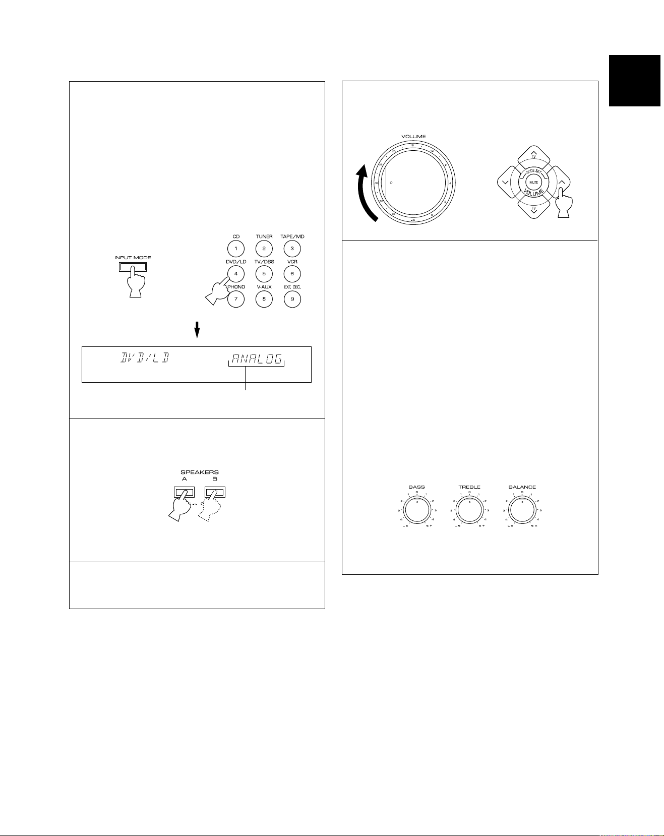
4 For a DVD/LD or TV/DBS source, the current input
mode is also shown.
* To change the input mode for the DVD/LD or TV/DBS
source, press INPUT MODE (or the button that you
have pressed to select the program source in step 3
on the remote control transmitter) once or more until
the desired input mode (AUTO or ANALOG) is shown
on the display. (See page 30 for details on switching
the input mode.)
Front panel Remote control
or
7 Adjust the volume to the desired output level.
Front panel Remote control
or
8 If desired, adjust BASS, TREBLE, BALANCE, etc.
and use the digital sound field processor (see
page 38).
BASS: Turn this control clockwise to increase (or
counterclockwise to decrease) the lowfrequency response.
TREBLE: Turn this control clockwise to increase (or
counterclockwise to decrease) the highfrequency response.
Input mode
5 Select the main speakers to be used.
Front panel
* If you use two main speaker systems, press both A and B.
6 Play the source. (See page 32 for detailed information
on tuning.)
BALANCE: Adjust the balance of the output volume
from the left and right speakers to
compensate for sound imbalance caused
by the speaker location or listening room
conditions.
Front panel
* These controls are only effective for the sound from the
main speakers.
When you have finished using this unit
Press STANDBY/ON on the front panel again or POWER on
the remote control transmitter to set this unit to the standby
mode.
29
Page 30

Notes on using INPUT
• The audio source selected by INPUT will not be played if the
“TAPE/MD MON” indicator lights up or if “EXT. DECDR” is
displayed.
• If you select INPUT for a video source without canceling the
selection of T APE/MD MON / EXT. DECODER on the front
panel (or T APE/MD or EXT. DEC. on the remote control
transmitter), the play back result will be a video image from
the video source and the sound from the audio source
selected by T APE/MD MON / EXT. DECODER on the front
panel (or T APE/MD or EXT. DEC. on the remote control
transmitter).
• Once you start playing a video source, the video image will
not be interrupted even if INPUT for an audio source is
selected.
• When you select a program source by using INPUT, the DSP
program (or no DSP program) that was being used when the
same program source was selected the last time, will be
automatically recalled.
Switching the input mode
(for DVD/LD and TV/DBS)
This unit allows you to switch the input mode only for those
sources connected to the DVD/LD and TV/DBS input terminals
(on the rear panel of this unit) that input two or three types of
signal.
The following two input modes are provided:
AUTO For a source connected to the DVD/LD input
terminals
This mode is automatically selected when you turn on
the power to this unit. In this mode, the input signal is
automatically selected in the following order of priority:
1. Digital input signal from the COAXIAL terminal
2. Digital input signal from the OPTICAL terminal
3. Analog input signal
For a source connected to the TV/DBS input
terminals
This mode is selected when you turn on the power to
this unit if the AUTO position is selected for “INPUT” in
the SET MENU mode. (See page 45 for details.) In
this mode, the input signal is automatically selected in
the following order of priority:
1. Digital input signal from the OPTICAL terminal
2. Analog input signal
ANALOG
In this mode, only an analog input signal is selected,
even if a digital signal is input at the same time.
Select this mode when you want to use the analog
input signal instead of the digital input signal.
Notes on input mode selection
• To play back a source that is Dolby Digital-decoded, set the
input mode to AUTO.
• For the TV/DBS source only, the input mode selected for
“INPUT” in the SET MENU mode is effective when you turn
on the power to this unit.
• When you want to enjoy a source which has normal
2-channel signals with a Dolby Pro Logic Surround program,
select the ANALOG mode.
• In the AUTO mode, there may be a case, depending on the
LD player or DVD player, that when you search for a source
encoded with Dolby Digital during play and then play is
restored, the sound output is interrupted for a moment
because the digital input signal is selected again.
30
Page 31

2
1,4
TO RECORD A SOURCE ON TAPE OR MD
4 21
English
1 Select the source to be recorded.
Front panel Remote control
or
2 Play the source and then turn up the volume to confirm
the program source. (See page 32 for detailed
information on tuning.)
Front panel Remote control
or
4 When a tape deck or MD recorder is being used for
recording, you can monitor the sounds being recorded
by pressing TAPE/MD MON / EXT. DECODER on the
front panel or T APE/MD on the remote control
transmitter so that the “TAPE/MD MON” indicator lights
up on the display.
Front panel Remote control
or
Notes
• The settings of DSP and VOLUME, BASS, TREBLE and
BALANCE have no effect on the material being recorded.
• A source that is connected to this unit only through the digital
terminals cannot be recorded by a tape deck, MD recorder or
VCR connected to this unit.
• Please check the copyright laws in your country to record
from records, compact discs, radio, etc. Recording of
copyright material may infringe copyright laws.
If you use a video source that has scrambled or encoded
signals to prevent it from being dubbed, there may be a case
that the picture itself will be affected by those signals.
3 Begin recording on the tape deck, MD recorder or VCR
connected to this unit.
31
Page 32

TUNING OPERATIONS
Set INPUT on the front panel to the TUNER position. When using the remote control transmitter, press AMP<TUNER> on the
component selector and then press TUNER on the input selector.
Normally, if station signals are strong and there is no interference, quick automatic-search tuning (AUTOMATIC TUNING) is
possible. However, if the signal from the station you want to select is weak, you must tune in to it manually (MANUAL TUNING).
32
1
AUT OMA TIC TUNING
1 Select the reception band (FM or AM) and confirm it on
the display.
Front panel
or
2 Press TUNING MODE so that the “AUTO TUNING”
indicator lights up on the display.
Front panel
Lights up
3 To tune in to a higher frequency, press the UP side of
TUNING once.
To tune in to a lower frequency, press the DOWN side
of TUNING once.
MANUAL TUNING
1 Select the reception band (FM or AM) and confirm it on
the display.
Front panel
or
2 Press TUNING MODE.
Front panel
Confirm that the “AUTO
TUNING” indicator goes off.
3 Tune in manually to the desired station.
Front panel
Front panel
* If the station where the tuning search stops is not the
desired one, press once more.
* If the tuning search does not stop at the desired station
(because the signal from the station is weak), take the
manual tuning procedure.
32
* To continue the tuning search, press and hold the button.
Note
If you tune in manually to an FM station, it will be automatically
received in monaural mode to increase the signal quality.
Page 33

MANUAL PRESET TUNING
This unit can store station frequencies to be selected by tuning. With this function, you can recall any desired station simply by
selecting the preset station number with which it was stored. Up to 40 stations (8 stations x 5 groups) can be stored.
English
2 4
To store stations
1 Tune in to the desired station.
(See the previous page for the tuning procedure.)
2 Press A/B/C/D/E once or more to select the desired
group (A to E) of preset stations and confirm it on the
display.
Front panel
3
4 Select the preset station number with which you want to
store the station before the “MEMORY” indicator goes
off from the display.
Front panel
3 Press MEMORY so that the “MEMORY” indicator
flashes for about five seconds.
Front panel
Flashes
The displayed station has been stored as A1.
* In the same way, store other stations as A2, A3 ... A8.
* You can store more stations as preset station numbers in
other groups in the same way by selecting another group
in step 2.
33
Page 34

1 2
2
1
To recall a preset station
1 Select the group of preset stations.
Front panel Remote control
Notes
• A new setting can be stored in place of the former one.
• For presets, the setting of the reception mode (stereo or
monaural) is stored along with the station frequency.
or
2 Select the preset station number.
Front panel Remote control
or
Memory back-up
The memory back-up circuit prevents the stored data from
being lost when this unit is set in the standby mode. If,
however, the power plug is disconnected from the AC outlet or
the power is cut due to temporary power failure for more than
one week, the memory will be erased. If so, it can be re-stored
by simply following the preset tuning procedure.
34
Page 35

AUTOMATIC PRESET TUNING (for FM stations only)
You can also make use of the automatic preset tuning function for FM stations only. This function enables the unit to perform
automatic tuning and to sequentially store FM stations with strong signals. Up to 40 stations can be stored automatically in the
same way as that for manual preset tuning on page 33. Note that a new setting can be stored in place of the former one.
3 1
42
To store stations
English
1 Select the FM band.
Front panel
2 Press TUNING MODE so that the “AUTO TUNING”
indicator lights up on the display.
Front panel
Lights up
3 Press MEMORY and hold for about three seconds.
Front panel
Flashes
4 To tune in to higher frequencies, press the UP side of
TUNING once.
To tune in to lower frequencies, press the DOWN side
of TUNING once.
Front panel
* If TUNING is not pressed, the automatic preset tuning
soon begins automatically toward higher frequencies.
Automatic preset tuning begins from the frequency currently
displayed. Received stations are sequentially stored as A1,
A2 ... A8.
* If more than 8 stations are received, they are stored as the
preset station numbers in other groups (B, C, D and E) in
that order.
If you want to store the first station received by automatic
preset tuning as a desired preset station number
For example, if you want to store the first received station as C5,
select “C5” while “A1”, the “MEMORY” indicator and the “AUTO
TUNING” indicator flash after pressing MEMORY in step 3. Then
press TUNING. The first received station is stored as C5, and the
next stations as C6, C7 ... sequentially .
If stations have been stored up to E8, automatic preset tuning
automatically stops.
When automatic preset tuning is complete
The display shows the frequency of the last preset station.
Check the contents and the number of preset stations by
following the procedure in the section “To recall a preset
station” on page 34.
35
Page 36

Notes
• You can manually replace a preset station with another FM or AM station by simply following the procedure in the section “To
store stations” on page 33.
• Even if the number of received stations is not enough to be stored up to E8, the search is automatically ended after searching all
frequencies.
• With this function, only FM stations with sufficient signal strength are automatically stored. If the station you want to store is weak
in signal strength, tune in to it manually in monaural sound and store it by following the procedure in the section “To store
stations” on page 33.
EXCHANGING PRESET STATIONS
You can exchange the assigment of two preset stations with each other as shown below.
2,4
Example
If you want to change the preset station from “E1” to “A5”, or vice versa.
1 Recall preset station “E1” by following the procedure in
the section “To recall a preset station” on page 34.
2 Press EDIT.
Front Panel
Flashes
3 Next, recall preset station “A5” by following the same
procedure as in step 1.
Flashes
4 Press EDIT once more.
Front Panel
Shows the exchange of
stations has been
completed.
36
Page 37

SETTING THE SLEEP TIMER
The SLEEP timer can be used to make this unit automatically switch to the standby mode. When you are going to sleep while
enjoying a broadcast or other desired program source, this timer function is useful. The SLEEP timer can only be controlled with
the remote control transmitter.
Notes
• To set the SLEEP timer for this unit, press AMP<TUNER>, T APE/MD, CD or DVD/LD on the component selector.
• The components for which the SLEEP timer is effective are the sources connected to the SWITCHED AC OUTLET(S) on the rear
panel of this unit.
1
English
To set the SLEEP time
1 Press SLEEP once or more to select the desired
SLEEP time.
Remote control
The SLEEP time is displayed.
Flashes
Each time you press SLEEP, the SLEEP time will change as
follows:
(Minutes)
120 90 60 30
To cancel the selected SLEEP time
Remote control
Press SLEEP once or more so that “SLEEP OFF” appears on
the display. (It will soon disappear and the “SLEEP” indicator
will go off from the display.)
Note
The SLEEP timer setting can also be canceled by setting the
unit in the standby mode with STANDBY/ON on the front panel
(or POWER on the remote control transmitter) or by
disconnecting the power plug of the unit from the AC outlet.
The SLEEP timer is off (SLEEP OFF).
(This is the state before SLEEP
is pressed.)
The “SLEEP” indicator soon lights up and the display returns
to the indication before the SLEEP timer was set.
2 The unit will be switched to the standby mode
automatically at the selected SLEEP time.
37
Page 38

USING THE DIGITAL SOUND FIELD PROCESSOR (DSP
This unit incorporates a sophisticated, multi-program digital sound field processor. The processor allows you to electronically
expand and change the shape of the audio sound field from both audio and video sources, creating a theater-like experience in
your listening room. You can create outstanding audio sound by selecting a suitable sound field program (this will, of course,
depend on what you are listening to) and adding any desired adjustments.
The following list gives you a brief description of the sound fields produced by each of the DSP programs. Keep in mind that most
of these are precise digital re-creations of actual acoustic environments. The data for these sound fields were recorded at actual
locations using sophisticated sound field measurement equipment.
Note
The channel level balance between the left and right rear speakers may vary depending on the sound field you are
listening to. This is due to the fact that most of these sound fields are a re-creation of actual acoustic environments.
BRIEF OVERVIEW OF DIGITAL SOUND FIELD PROGRAMS
)
No. PROGRAM
1 DOLBY PRO LOGIC ( )
This functions when the input signal is analog or
PCM audio, or encoded with Dolby Digital in
2-channel.
Speaker output: main, center, rear
DOLBY DIGITAL (
This functions when the input signal is encoded with
Dolby Digital (not in 2-channel).
Speaker output: main, center, rear
2 DOLBY PRO LOGIC ENHANCED
(
)
This functions when the input signal is analog or
PCM audio, or encoded with Dolby Digital in
2-channel.
Speaker output: main, center, rear
DOLBY DIGITAL ENHANCED
(
This functions when the input signal is encoded with
Dolby Digital (not in 2-channel).
Speaker output: main, center, rear
)
)
FEATURES
This reproduces video discs, video tapes and similar sources
which are Dolby Surround encoded and bear the “DOLBY
SURROUND” logo.
The built-in Dolby Pro Logic Surround decoder or Dolby Digital
decoder precisely reproduces the sounds and sound effects of
a source encoded with Dolby Surround. The realization of a
highly efficient decoding process improves crosstalk and
channel separation and makes sound positioning smoother
and more precise.
Note: If the main channel sound is considerably altered by
overadjusting BASS or TREBLE, it may not produce suitable
surround sound.
This reproduces video discs, video tapes and similar sources
which are Dolby Surround encoded and bear the “DOLBY
SURROUND” logo.
This program ideally simulates the multi-surround speaker
systems of the 35 mm film theater. Dolby Surround decoding
is precisely performed without altering the original sound
orientation. The surround effects produced by this sound field
fold around the viewer naturally from the rear to the left and
right and toward the screen.
3 70 mm MOVIE THEATER
(
)
This functions when the input signal is analog or
PCM audio, or encoded with Dolby Digital in
2-channel.
Speaker output: main, center, rear
DIGITAL MOVIE THEATER
(
This functions when the input signal is encoded with
Dolby Digital (not in 2-channel).
Speaker output: main, center, rear
)
38
This is ideal for reproducing video discs, video tapes and
similar sources which are Dolby Surround encoded and bear
the “DOLBY SURROUND” logo.
This program is ideal for precisely reproducing the sound
design of the newest 70 mm/Dolby Digital multi-track films.
The sound field is similar to that of the newest movie theaters,
so the reverberations of the sound field itself are restrained as
much as possible. The three-dimensional feeling of the sound
field is emphasized, and dialog is precisely oriented on the
screen. You can enjoy watching Sci-Fi, adventure movies, etc.
with considerable presence.
Page 39

No. PROGRAM
FEATURES
English
4 MONO MOVIE
(
)
This functions when the input signal is analog or
PCM audio, or encoded with Dolby Digital in
2-channel.
Speaker output: main, center, rear
(
This functions when the input signal is encoded
with Dolby Digital (not in 2-channel).
Speaker output: main, center, rear
5 TV SPORTS
(
This functions when the input signal is analog or
PCM audio, or encoded with Dolby Digital in
2-channel.
Speaker output: main, center, rear
(
This functions when the input signal is encoded
with Dolby Digital (not in 2-channel).
Speaker output: main, center, rear
6 DISCO
(
This functions when the input signal is analog or
PCM audio, or encoded with Dolby Digital in
2-channel.
Speaker output: main, rear
(
This functions when the input signal is encoded
with Dolby Digital (not in 2-channel).
Speaker output: main, center, rear
)
)
)
)
)
This program is designed specifically to enhance mono audio
sources. Compared to a strictly mono setting, the sound image
created in this mode is wider and slightly forward of the speaker
pair, lending an immediacy to the overall sound. It is particularly
effective when used with old mono movies, news broadcasting
and dialog.
This program is furnished with a tight sound field in which the
sound will not spread excessively on the front side, but the rear
surround side produces dynamic sound expansion. This
program is the most suitable for sports events.
This program re-creates the acoustic environment of a lively
disco in the heart of a very lively city. The sound is dense and
highly concentrated. It is also characterized by a high-energy,
“immediate” sound.
7 ROCK CONCERT
(
)
This functions when the input signal is analog or
PCM audio, or encoded with Dolby Digital in
2-channel.
Speaker output: main, rear
(
This functions when the input signal is encoded
with Dolby Digital (not in 2-channel).
Speaker output: main, center, rear
8 CONCERT HALL
(
This functions when the input signal is analog or
PCM audio, or encoded with Dolby Digital in
2-channel.
Speaker output: main, rear
(
This functions when the input signal is encoded
with Dolby Digital (not in 2-channel).
Speaker output: main, center, rear
Note: When the NONE position is selected for “CNTR” in the SET MENU mode, no sound is output from the center speaker(s).
)
)
)
This program is ideally suited for rock music. You will
experience a very dynamic and lively sound field.
In this program, the center will appear to be deep behind the
main speakers, creating an expansive, large hall ambience.
Orchestra and opera music are suited to this sound field.
39
Page 40

PLAYING AN AUDIO/VIDEO SOURCE WITH THE DIGITAL SOUND FIELD
2
PROCESSOR (DSP) EFFECT
2
1 Follow steps 1 to 7 shown in “BASIC OPERATIONS” on
pages 28 to 29.
2 Select the desired DSP program that is suitable for the
source. When using the remote control transmitter,
press AMP<TUNER> on the component selector first.
Front panel Remote control
or
The name of the selected program appears
on the display.
3 If desired, adjust the delay time and the output level of
each speaker. (See pages 42 and 43 for details.)
Notes
• You can select a program for each of the program sources.
Once you select a program, it is linked with the program
source selected at that time. So, when you select the
program source next time, the same program is automatically
called.
• If you prefer to cancel the DSP function, press EFFECT. The
sound will be that of normal 2-channel stereo without a
surround sound effect.
• When a monaural sound source is played with DOLBY PRO
LOGIC or DOLBY PRO LOGIC ENHANCED, no sound can
be heard from the main speakers and the rear speakers.
Sound is heard only from the center speaker. However, if the
NONE position is selected for “CNTR” in the SET MENU
mode, the main speakers output the sound of the center
channel.
40
Page 41

This unit incorporates a Dolby Digital decoder and a Dolby Pro Logic Surround decoder for multi-channel sound reproduction of
sources encoded with Dolby Surround. The operation of these decoders can be controlled by selecting a corresponding DSP
program including the combined operation of YAMAHA DSP and Dolby Digital or Dolby Pro Logic Surround.
English
To enjoy a video source with Dolby Pro Logic
Surround or Dolby Digital-decoded
When you select the DOLBY PRO LOGIC/DOLBY DIGITAL,
DOLBY PRO LOGIC ENHANCED/DOLBY DIGITAL
ENHANCED or 70 mm MOVIE THEATER/DIGITAL MOVIE
THEATER program, and the input signal of the source is
2-channel stereo, Dolby Pro Logic Surround is decoded. When
a program is selected and the input signal of the source is
encoded with Dolby Digital, Dolby Digital is automatically
decoded.
* The following indicators on the display show you what sound
processing is being undertaken.
This lights up when Dolby Digital is being decoded and the
input signal of the selected source encoded with Dolby Digital
is not in 2-channel.
This lights up when the digital sound
field processor is turned on.
This lights up when Dolby Pro
Logic Surround is being decoded.
To cancel the sound effect
EFFECT on the front panel and on the remote control
transmitter make it simple to compare the normal stereo sound
with the fully processed sound effect.
To cancel the sound effect and monitor only the main sound,
press EFFECT. Press EFFECT once more to turn sound effect
on.
Front panel Remote control
or
Notes
• If the sound effect is canceled when signals encoded with
Dolby Digital are input to this unit, the signals of all channels
are mixed and are output from the main speakers.
• If EFFECT is pressed to turn sound effects off when Dolby
Digital is decoded, it may happen that the sound is output
faintly or not output normally, depending on the source. In
that case, press EFFECT to turn sound effects on, or use
input signals not encoded with Dolby Digital.
* In addition, for the DOLBY PRO LOGIC/DOLBY DIGITAL,
DOLBY PRO LOGIC ENHANCED/DOLBY DIGITAL
ENHANCED or 70 mm MOVIE THEATER/DIGITAL MOVIE
THEATER program, the name of the program on the display
will change according to the type of decoding. (See page 38
for details.)
Note
If the input signal of the source is encoded with Dolby Digital in
2-channel only, their sound processing is similar to that for
analog or PCM audio signals.
41
Page 42

ADJUSTING THE DELAY TIME AND SPEAKER OUTPUT LEVELS
When using the digital sound field processor with the Dolby Pro Logic Surround decoder or the Dolby Digital decoder, you can
adjust the delay time between the main sound and sound effect, and each speaker’s output level as you prefer.
1
2
1
2
Adjusting method
When adjusting with the remote control transmitter, press
AMP<TUNER> on the component selector.
1 Press TIME/LEVEL once or more until the name of the
item which you want to adjust appears on the display.
Front panel Remote control
or
When pressed, the selection changes as follows:
DELAY
CENTER
R SUR.
L SUR.
SWFR
Delay time
Center speaker output level
Right rear speaker output level
Left rear speaker output level
Subwoofer output level
2 Press + or – to adjust the settings for the delay time or
speaker output levels.
Front panel Remote control
or
3 Repeat steps 1 to 2 to adjust the settings of any other
item.
* Depending on the setting in the SET MENU mode, you
may not be able to select all items.
42
Page 43

English
Adjusting the delay time
You can adjust the time difference between the beginning of the
sound from the main speakers and the beginning of the sound
effect from the rear speakers.
The larger the value, the later the sound effect is generated.
This adjustment can be individually made to all programs.
Program
1. DOLBY PRO LOGIC
DOLBY DIGITAL
2. DOLBY PRO LOGIC ENHANCED
DOLBY DIGITAL ENHANCED
3. 70 mm MOVIE THEATER
DIGITAL MOVIE THEATER
4. MONO MOVIE
5. TV SPORTS
6. DISCO
7. ROCK CONCERT
8. CONCERT HALL
Notes
• Adding too much delay will cause an unnatural effect with
some sources.
• When + or – is pressed, the sound is momentarily
interrupted.
Control range (ms)
15 to 30
0 to 15
15 to 30
0 to 15
15 to 30
1 to 99
1 to 99
1 to 99
1 to 99
1 to 99
1 to 99
Preset value
20
5
20
5
20
16
49
9
40
16
44
Adjusting the output level of the center, right rear and left rear speakers, and subwoofer
If desired, you can adjust the sound output level of each
speaker even if the output level has already been set in
“SPEAKER BALANCE ADJUSTMENT” on pages 25 to 27.
Notes
• The output level of the center speaker cannot be adjusted
when the DISCO, ROCK CONCERT or CONCERT HALL
program is selected, and the input signal is analog, PCM
audio, or encoded with Dolby Digital in 2-channel format.
Speakers
CENTER
RIGHT REAR
LEFT REAR
SUBWOOFER
Memory back-up
The memory back-up circuit prevents the stored data from being lost when this unit is set in the standby mode. If, however, the
power plug is disconnected from the AC outlet or the power is cut due to temporary power failure for more than one week, the
values for the delay time and the center/rear/subwoofer output levels you set the last time will automatically return to the preset
values. If so, they can be re-set by simply following the adjusting method on page 42.
Control range (dB)
MIN, –20 to +10
MIN, –20 to +10
MIN, –20 to +10
MIN, –20 to 0
• If the function “CNTR” in the SET MENU mode is set to the
NONE position, the sound output level of the center speaker
cannot be adjusted. This is because, in this mode, the center
sound is automatically output from the left and right main
speakers.
• Once the output level has been adjusted, the level will be the
same for all digital sound field programs.
Preset value
0
0
0
0
43
Page 44

ADJUSTMENTS IN THE “SET MENU” MODE
The following ten types of functions maximize the performance of your system and expand your enjoyment for audio listening and
video watching.
1. CNTR (CENTER SPEAKER)
2. REAR (REAR SPEAKERS)
3. MAIN (MAIN SPEAKERS)
4. BASS (LFE/BASS OUT)
5. M.LVL (MAIN LEVEL)
For details on “CNTR”, “REAR”, “MAIN”, “BASS” and “M.LVL”,
see page 23. (Once you have selected the appropriate modes,
you do not have to change settings unless any alteration is
made in your speaker system.)
LFE [Adjusting the output level of the
LFE (low frequency effect) channel]
Control range: –20 dB to 0 dB (in 1 dB steps)
Preset value: 0 dB
* This adjustment is effective only when Dolby Digital is
decoded and the signals of the selected source encoded with
Dolby Digital contain LFE signals.
This adjusts the output level of the LFE channel. If the LFE
signals are mixed with signals of other channels to output them
from the same speakers, the ratio of the LFE signal level to the
level of the other signals is adjusted.
(See page 7 for details about the LFE channel.)
6. LFE (LFE LEVEL)
7. D.RNG (DYNAMIC RANGE)
8. C.DELAY (CENTER DELAY)
9. GUARD (MEMORY GUARD)
10. INPUT (INPUT MODE)
D.RNG (Adjusting the dynamic range)
Choices: MAX/STD/MIN
Preset position: MAX
* This adjustment is effective only when Dolby Digital is
decoded.
MAX: “Dynamic range” is the difference between the
maximum level and the minimum level of sounds.
Sounds on a movie originally designed for movie
theaters feature very wide dynamic range. Dolby
Digital technology can modify the original sound
track into a home audio format with this wide
dynamic range unchanged.
In this position, a source encoded with Dolby Digital
is reproduced in the original sound track’s wide
dynamic range providing you with powerful sounds
just like those in a movie theater. Selecting this
position will be even better if you can listen to a
source at a high output level in a room specially
soundproofed for audio/video enjoyment.
STD (Standard):
Powerful sounds of extremely wide dynamic range
are not always suitable for home use. Depending on
the condition of your listening environment, it may
not be possible to increase the sound output level as
high as that in a movie theater. However, at the
normal level suitable for listening to in your room, the
low-level parts of source sound often cannot be
heard well because they will be lost among noise in
your environment. Dolby Digital technology has also
made it possible to reduce an original sound track’s
dynamic range for a home audio format by
“compressing” the sound data.
In this position, a source encoded with sound Dolby
Digital is reproduced in the “compressed” dynamic
range of sound that is suitable for low-level listening.
MIN: In this position, the dynamic range is more reduced
than in the STD position.
Selecting this position will be effective when you
must listen to a source at a low level.
44
Page 45

English
C.DELAY [Adjusting the delay of
center sounds (dialog, etc.)]
Control range: 0 ms to 5 ms (in 1 ms steps)
Preset value: 0 ms
* This adjustment is effective only when Dolby Digital is
decoded and the signals of the selected source encoded with
Dolby Digital contain center-channel signals.
This adjusts the delay between the main sound (on the main
channels) and dialog, etc. (on the center channel).
The larger the value, the later the dialog, etc. is generated.
This is for making sounds from the left main, center and right
main speakers reach your listening position at the same time.
This is achieved by delaying the sound from the center speaker
if the distance from the center speaker to your listening position
is shorter than the distance from the left or right main speaker
to your listening position.
GUARD
Adjusting method
Adjustments should be made while watching the information on
this unit’s display.
When adjusting with the remote control transmitter, press
AMP<TUNER> on the component selector.
Press SET MENU once or more so that the function which you
want to change appears on the display.
Front panel Remote control
or
Press + or – to select any desired setting or to edit parameters
of the function.
Choices: ON/OFF
Preset position: OFF
If you wish to prevent accidental alterations to SET MENU and
other adjustments on this unit, select ON. The following
functions on this unit can be locked by this operation:
• Functions in the SET MENU mode
• Functions in the TIME/LEVEL mode
• Functions when using TEST
INPUT (Selecting the initial input mode of
the sources connected to the TV/DBS
input terminals)
Choices: AUTO/LAST
Preset position: AUTO
You can designate the input mode that is automatically selected
when the power for this unit is switched on for only the sources
connected to the TV/DBS input terminals of this unit.
AUTO: In this position, the AUTO input mode is always
selected when the power for this unit is switched on.
LAST: In this position, the input mode you selected last time
is memorized and will not be changed when the
power is switched on again.
Front panel Remote control
or
Repeat these steps to change or adjust the settings of any
other function.
Memory back-up
The memory back-up circuit prevents the stored data from
being lost when this unit is set in the standby mode. If,
however, the power plug is disconnected from the AC outlet or
the power is cut due to temporary power failure for more than
one week, the settings of the SET MENU mode will
automatically return to the factory settings. If so, they can be
re-set by simply following the procedure above.
* See page 30 for details on switching the input mode.
45
Page 46

REMOTE CONTROL TRANSMITTER
You can use the remote control transmitter to control not only this unit but also other components connected to it. The remote
control transmitter is factory set to control this unit and most YAMAHA audio components. To control other brands of components,
you must preset the remote control transmitter with manufacturers’ codes listed on pages 113 to 117.
Components which can be controlled
There are eight buttons on the component selector that you can select to control connected components with this remote control
transmitter. For example, if CD on the component selector is pressed, the remote control transmitter selects the CD operation
mode, allowing the CD player to be operated by the buttons on the remote control transmitter.
AMP<TUNER>
You can perform the basic operations of this unit,
set the speaker level, and set the DSP level and
delay time in the AMP<TUNER> mode.
CD
The code for a YAMAHA CD player is preset.
DVD/LD & DVD MENU
An LD player can be controlled in the DVD/LD
mode. A DVD player can be controlled in the
DVD/LD and DVD MENU modes. The code for
a YAMAHA DVD player is preset. If the remote
control transmitter will not operate your
YAMAHA DVD player, you need to preset code
number “0048”.
Notes
1. You can preset the code for the manufacturer of your component after pressing the shaded buttons in the illustration above.
Note that you can preset only one code for one mode. See “SETUP CODES” on page 53 for details.
2. In the DVD/LD and DVD MENU modes:
• Be sure to press DVD/LD on the component selector before presetting the code for the DVD/LD player. The code preset in
the DVD/LD mode is also simultaneously preset in the DVD MENU mode. You cannot preset the code for a DVD player in
the DVD MENU mode.
• DVD MENU operations cannot be performed for some DVD players.
3. When using a second (and third) VCR: (See “To use a second (and third) VCR” on page 53 for details.)
• If you are not using a CBL/DBS (cable TV or DBS tuner), the second (or third) VCR can be preset in the CBL/DBS mode.
• If you are not using a DVD player, the second (or third) VCR can be preset in the DVD MENU mode. Note that in this case
you must preset the code for an LD player in the DVD/LD mode even if an LD player is not being used.
TAPE/MD
The code for a YAMAHA tape deck is
preset. (The code for the YAMAHA MD
recorder can also be preset.)
VCR
A VCR can be controlled.
CBL/DBS
A cable television or DBS tuner can be
controlled.
TV
A television can be controlled.
46
Page 47

The lightly marked buttons do not function.
English
■AMP<TUNER> MODE
Press AMP<TUNER>.
POWER
Each time this button is pressed, the unit
will switch between the power on and
standby modes.
TEST
This button outputs a test tone for adjusting
the output levels of the speakers.
A/B/C/D/E & PRESET +/–
These buttons select a preset FM or AM
broadcast.
A/B/C/D/E: To select a group of preset
stations.
PRESET +/–: To select the preset station
number.
MUTE
This button mutes the sound. To cancel mute,
press this button once more, or press any
operation buttons of this unit.
Note:
TV VOLUME and TV INPUT function if you have preset the code for your TV.
Input selector
These buttons select the program source.
CD: To play a CD
TUNER: To listen to an FM or AM
broadcast
TAPE/MD: To play a tape or MD
DVD/LD: To play a DVD or LD
TV/DBS: To watch a television or
satellite broadcast
VCR: To play a video tape
PHONO: To play an analog record
V-AUX: To use a camcorder
EXT. DEC.: To output the signals of a DTS
or other multi-channel
decoder
EFFECT
This button switches the DSP
program on or off.
TV VOLUME
VOLUME (
These buttons adjust the volume level.
SLEEP
This button sets the SLEEP timer.
+/–
These buttons adjust the settings of the SET
MENU mode and the TIME/LEVEL mode.
TIME/LEVEL
This button selects the item in the TIME/LEVEL
mode.
)
TV INPUT
PRG+/PRG–
These buttons select a DSP program.
SET MENU
This button selects functions in the SET
MENU mode.
47
Page 48

The lightly marked buttons do not function. Please refer to the owner’s manual for details of each component.
■TAPE/MD MODE
POWER
(TAPE) When you have preset the code for
a YAMAHA tape deck, this button turns the
unit on. When you have preset the code for
another manufacturer, this button turns on
that component if it has a remote control
transmitter with a power button.
(MD) When you have preset the code for the
YAMAHA MD recorder, this button turns the
unit on.
Notes: •
TV VOLUME functions if you have preset the code for your TV.
• The code for the YAMAHA MD recorder can be preset.
Press T APE/MD.
INPUT
EFFECT
VOLUME
MUTE
SLEEP
REC/PAUSE
This button pauses recording on a tape
deck or MD recorder.
PLAY
This button plays a tape or an MD.
DIR A (TAPE)
This button selects the playing direction of
deck A.
SKIP– (MD)
This button skips to the previous track.
REWIND (TAPE)
This button rewinds a tape.
SEARCH (MD)
This button initiates a backward search on
the track that is playing to find the point from
which you want to listen.
TV VOLUME
DISPLAY (MD)
DECK A/B (TAPE)
This button selects double-cassette tape
deck A or B.
PAUSE (MD)
This button gives a pause in operation.
DIR B (TAPE)
This button selects the playing direction of
deck B.
SKIP+ (MD)
This button skips to the next track.
STOP
This button stops operation of a tape or
MD.
FAST FORWARD (TAPE)
This button winds a tape fast forward.
SEARCH (MD)
This button initiates a fast-forward search
on the track that is playing to find the point
from which you want to listen.
48
Page 49

The lightly marked buttons do not function. Please refer to the owner’s manual for details of each component.
English
■CD MODE
Press CD.
POWER
When you have preset the code for a
YAMAHA CD player, this button turns the
unit on. When you have preset the code for
another manufacturer, this button turns on
that component if it has a remote control
transmitter with a power button.
Note: TV VOLUME and TV INPUT function if you have preset the code for your TV.
INPUT
VOLUME
MUTE
SLEEP
PLAY
This button plays a CD.
SKIP–
This button skips to the previous track.
SEARCH
This button initiates a backward search on
the track that is playing to find the point from
which you want to listen.
EFFECT
DISC SKIP +/–
(for the CD player with CD changer)
These buttons skip to the next or previous
CD.
TV VOLUME
DISPLAY
TV INPUT
PAUSE
This button gives a pause in operation. The
button functions as P AUSE/STOP* for operating
YAMAHA CD player under factory setting.
SKIP+
This button skips to the next track.
STOP
This button stops operation. The button
functions as PAUSE/STOP* for operating
YAMAHA CD players.
SEARCH
This button initiates a fast-forward search
on the track that is playing to find the point
from which you want to listen.
* PAUSE/STOP function ... Press the button once to give a pause in operation and once more to stop operation.
49
Page 50

The lightly marked buttons do not function. Please refer to the owner’s manual for details of each component.
■DVD/LD MODE
Note: TV VOLUME and TV INPUT function if you have
preset the code for your TV.
Press DVD/LD.
POWER
(DVD) When you have preset the code for
a YAMAHA DVD player, this button turns
the unit on. When you have preset the
code for another manufacturer, this button
turns on that component if it has a remote
control transmitter with a power button.
(LD) When you have preset the code for a
YAMAHA LD player, this button turns the
unit on. When you have preset the code
for another manufacturer, this button turns
on that component if it has a remote
control transmitter with a power button.
VOLUME
MUTE
SLEEP
SKIP–
STOP
SEARCH
INPUT
EFFECT
DISC SKIP +/–
TV VOLUME
DISPLAY
TV INPUT
PAUSE
SKIP+
PLAY
SEARCH
■DVD MENU MODE
Press DVD MENU.
POWER
When you have preset the code for a YAMAHA DVD
player, this button turns the unit on. When you have
preset the code for another manufacturer, this button
turns on that component if it has a remote control
transmitter with a power button.
DISC SKIP +/–
VOLUME
MUTE
RETURN
MENU UP
MENU LEFT
MENU SELECT
TITLE
Note: TV VOLUME and TV INPUT function if you have
preset the code for your TV.
Numeric buttons
CLEAR
+10
TV VOLUME
INDEX
TV INPUT
MENU RIGHT
MENU DOWN
MENU
50
Page 51

The lightly marked buttons do not function. Please refer to the owner’s manual for details of each component.
English
■VCR MODE
Note: TV VOLUME, TV INPUT and TV SLEEP function if you
have preset the code for your TV.
Press VCR.
VCR POWER
CHANNEL
EFFECT
VCR CHANNEL +/–
VOLUME
MUTE
TV SLEEP
VCR REC
Press this button twice
to start recording.
VCR PLAY
VCR REWIND
CHANNEL ENTER
TV VOLUME
DISPLAY
TV INPUT
VCR PAUSE
VCR STOP
VCR
FAST FORWARD
■TV MODE
Note: You can control your VCR if you have preset the code for
it.
Press TV.
TV POWER
CHANNEL
EFFECT
TV CHANNEL +/–
VOLUME
TV MUTE
TV SLEEP
VCR REC
Press this button twice.
VCR PLAY
VCR REWIND
CHANNEL ENTER
TV VOLUME
DISPLAY
TV INPUT
VCR PAUSE
VCR STOP
VCR
FAST FORWARD
■CBL/DBS MODE
Note: TV VOLUME, TV INPUT and TV SLEEP
function if you have preset the code for your TV.
CBL/DBS POWER
CBL/DBS CHANNEL +/–
MENU LEFT
MENU SELECT
CHANNEL
VOLUME
MUTE
TV SLEEP
RECALL
Press CBL/DBS.
+100
CHANNEL ENTER
TV VOLUME
DISPLAY
TV INPUT
MENU UP
MENU RIGHT
MENU DOWN
MENU
51
Page 52

NOTES ABOUT THE REMOTE CONTROL TRANSMITTER
Battery installation Remote control transmitter operation range
Remote control
sensor
2
1
3
Battery replacement
If the remote control transmitter operates only when it is close
to the unit, the batteries are weak. Replace all batteries with
new ones.
Be sure to replace batteries within about two minutes. If it
takes longer than two minutes, the codes preset for the
remote control transmitter will return to the factory-set.
Notes
• Use only AAA, R03, UM-4 batteries for replacement.
• Be sure the battery polarity is correct. (See the illustration
inside the battery compartment.)
• Remove the batteries if the remote control transmitter will not
be used for an extended period of time.
• If the batteries have leaked, dispose of them immediately.
Avoid touching the leaked material or letting it come into
contact with clothing, etc. Clean the battery compartment
thoroughly before installing new batteries.
Within approximately
6 m (20 feet)
Notes
• There should be no large obstacles between the remote
control transmitter and the unit.
• If the remote control sensor is directly illuminated by strong
lighting (especially an inverter type of fluorescent lamp, etc.),
it might cause the remote control transmitter not to work
correctly. In this case, reposition the unit to avoid direct
lighting.
52
Page 53

SETUP CODES
Presetting the remote control transmitter
Perform the presetting procedure for each component you want to control with the remote control transmitter.
Note: If your component does not respond to any of the codes listed for the manufacturer, use the original remote control
transmitter that was supplied with the component.
English
To control your components
(MD recorder, DVD player,
TV, etc.)
1. Turn on the component to be used.
2. Press the component selector which
matches the component to be
controlled (TAPE/MD, DVD/LD, TV
etc.).
3. Press both VOLUME buttons (
) for about four seconds at the
same time so that the indicator
flashes twice.
4. Use the numeric buttons to enter the
four-digit manufacturer’s code for
the component to be used. Make
sure that the indicator flashes twice.
If the indicator does not flash, repeat
step 3 and re-enter the code.
5. Press POWER (or any other button)
on the remote control transmitter to
check if you have preset the code
correctly. If the component cannot
be controlled by the remote control
transmitter, try entering another
code for the same manufacturer.
To use a second (and third) VCR
You can control a second (and/or third)
VCR in the CBL/DBS and DVD MENU
modes if a CBL (or DBS) or DVD player
is not being used.
If you want to control a second (and/or
third) VCR in the DVD MENU mode, you
must preset the code for an LD player in
that mode.
1. Turn on the VCR to be used.
2. Press CBL/DBS or DVD MENU on
the component selector.
3. Press both VOLUME buttons (
) for about four seconds at the
same time so that the indicator
flashes twice.
4. Use the numeric buttons to enter the
four-digit code for the second (or
third) VCR. Make sure that the
indicator flashes twice. If the
indicator does not flash, repeat step
3 and re-enter the code.
5. Press POWER (or any other button)
on the remote control transmitter to
check if you have preset the code
correctly. If the VCR cannot be
controlled by the remote control
transmitter, try entering another
code for the same manufacturer.
Returning to the factory-set
codes
To return all components to the factoryset codes, follow these steps.
1. Press a button on the component
selector other than AMP<TUNER>.
2. Press both VOLUME buttons (
) for about four seconds at the
same time so that the indicator
flashes twice.
3. Enter the code number “9990”.
4. Make sure that the indicator flashes
twice.
To return each component to the factoryset codes, follow these steps.
1. Press the component selector which
matches the component to be
returned to the factory-set codes.
2. Press both VOLUME buttons (
) for about four seconds at the
same time so that the indicator
flashes twice.
3. Enter the code number “0000”.
4. Make sure that the indicator flashes
twice.
The following codes are preset by the
factory.
Factory-set codes
Component
selector
TV TV 0101
CBL/DBS DBS tuner 0006
VCR VCR 0002
DVD/LD DVD player
CD CD player
TAPE/MD Tape deck
We recommend that you write all code
numbers you have preset on the “Quick
Reference Card”.
Component Code
0008 Y AMAHA
0005 Y AMAHA
0004 Y AMAHA
53
Page 54

TROUBLESHOOTING
If the unit fails to operate normally, check the following points to determine whether the fault can be corrected by the simple
measures suggested. If it cannot be corrected, or if the fault is not listed in the SYMPTOM column, disconnect the power cord and
contact your authorized YAMAHA dealer or service center for help.
SYMPTOM
The unit fails to turn on when
STANDBY/ON is pressed, or set in
the standby mode suddenly soon
after the power has been turned on.
The unit does not work normally.
No sound or no picture.
The sound suddenly goes off.
Only one side speaker outputs
sound.
Amplifier
A “humming” sound can be heard.
The volume level is low while
playing a record.
The volume level cannot be
increased, or the sound is distorted.
No sound from the effect speakers.
No sound from the rear speakers.
CAUSE
The power cord is not plugged in or the
plug is not completely inserted.
The IMPEDANCE SELECTOR switch
on the rear panel is not fully set at the
upper or lower end.
The internal microcomputer has been
frozen by an external electric shock
(lightning, excessive static electricity,
etc.) or by a power supply with low
voltage.
Incorrect output cord connections.
Appropriate program source has not
been selected.
SPEAKERS have not been set
properly.
The speaker connections are not
secure.
The protection circuit has been
activated because of a short circuit, etc.
The SLEEP timer has functioned.
Incorrect setting of BALANCE.
Incorrect cord connections.
Incorrect cord connections.
No connection from the turntable to the
GND terminal.
The record is being played on a
turntable with an MC cartridge.
The component connected to the REC
OUT terminals of this unit is in the
standby mode.
The sound effect is set off.
A Dolby Surround decoding program is
being used with material not encoded
with Dolby Surround.
The sound output level of the rear
speakers is set to minimum.
A monaural sound source is being
played in the DOLBY PRO LOGIC or
DOLBY PRO LOGIC ENHANCED
program.
REMEDY
Firmly plug in the power cord.
Slide the switch fully to the upper or
lower end.
Set the unit in the standby mode and
disconnect the AC power cord from the
AC outlet. After about 30 seconds have
passed, connect the power cord and
operate the unit again.
Connect the cords properly. If the
problem persists, the cords may be
defective.
Select an appropriate program source
by INPUT.
Set SPEAKERS corresponding to the
speakers in use to the ON position.
Secure the connections.
Set the unit in the standby mode and
then switch on again to reset the
protection circuit.
Cancel the SLEEP timer.
Adjust it to the appropriate position.
Connect the cords properly. If the
problem persists, the cords may be
defective.
Firmly connect the audio plugs. If the
problem persists, the cords may be
defective.
Make the GND connection between the
turntable and this unit.
The turntable should be connected to
the unit through the MC head amplifier.
Turn on the power to the component.
Press EFFECT to turn it on.
Use a different sound field program.
Raise the sound output level of the rear
speakers.
Select another sound field program
suitable for the monaural sound source.
54
Page 55

English
SYMPTOM
No sound from the center speaker.
The sound field cannot be recorded.
Amplifier
The DVD/LD, TV or DBS source
cannot be recorded on a tape deck,
MD recorder or VCR connected to
this unit.
FM stereo reception is noisy.
There is distortion and clear
reception cannot be obtained even
FM
with a good FM antenna.
The desired station cannot be tuned
in with the automatic tuning method.
Previously preset stations can no
longer be tuned in.
The desired station cannot be tuned
in with the automatic tuning method.
There are continuous crackling and
AM
hissing noises.
There are buzzing and whining
noises (especially in the evening).
<China and General models only>
Although you do the operations to
recall a preset station, the station
cannot be tuned in, or a station other
FM/AM
than the preset one is tuned in.
The remote control transmitter does
not work.
Remote control transmitter
CAUSE
The input signals of the source encoded
with Dolby Digital do not have center
channel signals.
The sound output level of the center
speaker is set to minimum.
The function “CNTR” in the SET MENU
is set to the NONE position.
Incorrect sound field program selection.
It is not possible to record the sound
field on a tape deck or MD recorder
connected to the unit’s REC OUT
terminals.
The DVD/LD player, TV or DBS tuner is
connected to the unit by only the digital
terminals.
The characteristics of FM stereo
broadcasts may cause this problem
when the transmitter is too far away or
the antenna input is poor.
There is multipath interference.
The station is too weak.
This unit has been unplugged for a long
period.
The signal is weak or antenna
connections are loose.
Noise will result from lightning,
fluorescent lamps, motors, thermostats
and other electrical equipment.
A television set is being used nearby.
Some of the preset station data has
been modified because the setting of
the FREQUENCY STEP switch was
changed after storing the station data.
Direct sunlight or lighting (from an
inverter type of fluorescent lamp, etc.) is
striking the remote control sensor of the
this unit.
The manufacturer’s code has not been
set properly.
The proper manufacturer’s code for the
component to be controlled has not
been set.
The component to be controlled has not
been selected.
REMEDY
Refer to the instruction for the source
being currently played.
Raise the sound output level of the
center speaker.
Select the LARGE or SMALL position.
Select the appropriate program.
Make additional connections between
the analog terminals.
Check the antenna connections.
Try using a high-quality directional FM
antenna.
Set TUNING MODE to the manual
tuning mode.
Adjust antenna position to eliminate
multipath interference.
Use the manual tuning method.
Use a high-quality directional FM
antenna.
Repeat the presetting procedure.
Tighten the AM loop antenna
connections and rotate it for best
reception.
Use the manual tuning method.
Use an outdoor antenna and a ground
wire. This will help somewhat, but it is
difficult to eliminate all noise.
Relocate this unit away from the TV.
Preset the stations again by following
the preset tuning procedure.
Change the position of the unit.
Set the code again.
Try entering another code for the same
manufacturer.
Press the component selector which
matches the component to be
controlled.
55
Page 56

SYMPTOM
The sound is degraded when
listening with the headphones to a
CD player or tape deck that is
connected to this unit.
Others
There is noise interference from
digital or high-frequency equipment
or the unit.
CAUSE
The unit is in the standby mode.
The unit is too close to the digital or
high-frequency equipment.
REMEDY
Turn on the power to the unit.
Move the unit further away from those
equipment.
56
Page 57

SPECIFICATIONS
English
AUDIO SECTION
Minimum RMS Output Power
8 ohms, 20 Hz to 20 kHz, 0.04% THD
MAIN L/R ........................... 60 W + 60 W
CENTER......................................... 60 W
REAR L/R.......................... 60 W + 60 W
8 ohms, 1 kHz, 0.07% THD
MAIN L/R ........................... 70 W + 70 W
CENTER......................................... 70 W
REAR L/R.......................... 70 W + 70 W
Maximum Power
[China and General models only]
8 ohms, 1 kHz, 10% THD
MAIN L/R ............................. 95 W + 95 W
CENTER ........................................... 95 W
REAR L/R ............................ 95 W + 95 W
Dynamic Power per Channel
(by IHF Dynamic Headroom measuring method)
MAIN L/R
8/6/4/2 ohms ................ 80/100/120/145 W
Dynamic Headroom (8 ohms)
[U.S.A. and Canada models only]
...................................................... 1.55 dB
Power Band Width
8 ohms, 30 W, 0.1% THD
.........................................10 Hz to 50 kHz
Damping Factor
MAIN L/R
8 ohms, 20 Hz to 20 kHz.......... 60 or more
Input Sensitivity/Impedance
PHONO MM ................... 2.5 mV/47 k-ohms
CD/TAPE·MD/DVD·LD/TV·DBS/VCR/
VIDEO AUX ................... 150 mV/47 k-ohms
EXT. DECODER
MAIN L/R .................... 150 mV/47 k-ohms
CENTER/SURROUND L/R/SUBWOOFER
.................................... 150 mV/40 k-ohms
Maximum Input Signal
PHONO MM
1 kHz, 0.1% THD .............100 mV or more
CD/TAPE·MD/DVD·LD/TV·DBS/VCR/
VIDEO AUX (EFFECT ON)
1 kHz, 0.5% THD .................2.2 V or more
Output Level/Impedance
REC OUT ..................... 150 mV/1.2 k-ohms
SUBWOOFER
(MAIN SP: SMALL) ........ 4.0 V/1.2 k-ohms
Headphones Jack Rated Output/Impedance
CD/TAPE·MD/DVD·LD/TV·DBS/VCR/
VIDEO AUX input,
1 kHz, 150 mV, 8 ohms ...... 0.4 V/390 ohms
Frequency Response (20 Hz to 20 kHz)
CD/TAPE·MD/DVD·LD/TV·DBS/VCR/
VIDEO AUX to MAIN L/R SP OUT
.................................................... 0±0.5 dB
RIAA Equalization Deviation
PHONO MM .................................. 0±0.5 dB
Total Harmonic Distortion (20 Hz to 20 kHz)
PHONO MM to REC OUT
1 V........................................0.02% or less
CD/TAPE·MD/DVD·LD/TV·DBS/VCR/
VIDEO AUX (EFFECT OFF) to MAIN SP
OUT
30 W/8 ohms......................0.025% or less
Signal-to-Noise Ratio (IHF-A Network)
PHONO MM to REC OUT
[U.S.A., Canada, China and General
models]
(5 mV, Input Shorted) ..........86 dB or more
[Australia and Singapore models]
(5 mV, Input Shorted) ..........81 dB or more
CD/TAPE·MD/DVD·LD/TV·DBS/VCR/
VIDEO AUX (EFFECT OFF) to MAIN SP
OUT
(150 mV, Input Shorted) ......96 dB or more
Residual Noise (IHF-A Network)
MAIN L/R SP OUT................ 150 µV or less
Channel Separation
(Vol. –30 dB, EFFECT OFF)
PHONO MM
(Input Shorted, 1 kHz/10 kHz)
....................60 dB or more/55 dB or more
CD/TAPE·MD/DVD·LD/TV·DBS/VCR/
VIDEO AUX
(Input 5.1 k-ohms Terminated, 1 kHz/10 kHz)
....................60 dB or more/45 dB or more
Tone Control Characteristics
BASS: Boost/cut ............. ±10 dB (50 Hz)
Turnover Frequency......... 350 Hz
TREBLE: Boost/cut ........... ±10 dB (20 kHz)
Turnover Frequency........ 3.5 kHz
Filter Characteristics
MAIN L/R, REAR L/R (SPEAKER: SMALL)
(H.P.F)..................... fc = 90 Hz, 12 dB/oct.
SUBWOOFER
(L.P.F) ..................... fc = 90 Hz, 18 dB/oct.
VIDEO SECTION
Video Signal Type
[U.S.A. and Canada models] .............. NTSC
[Australia and Singapore models] ......... PAL
[China and General models]....... NTSC/PAL
Video Signal Level ................ 1 Vp-p/75 ohms
Maximum Input Level .......... 1.5 Vp-p or more
Signal-to-Noise Ratio ...............50 dB or more
Monitor Output Frequency Response
.............................. 5 Hz to 10 MHz, –3 dB
FM SECTION
Tuning Range
[U.S.A. and Canada models]
..................................... 87.5 to 107.9 MHz
[Australia and Singapore models]
................................. 87.50 to 108.00 MHz
[China and General models]
100 kHz step ................ 87.5 to 108.0 MHz
50 kHz step .............. 87.50 to 108.00 MHz
50 dB Quieting Sensitivity (IHF)
(100% mod., 1 kHz)
Mono................................. 1.6 µV (15.3 dBf)
Stereo ................................ 23 µV (38.5 dBf)
Usable Sensitivity (DIN)
[Australia and Singapore models only]
Mono (S/N 26 dB) ........................... 0.9 µV
Stereo (S/N 46 dB)........................... 28 µV
Alternate Channel Selectivity (±400 kHz)
[U.S.A., Canada, China and General
models only] ....................................... 75 dB
Selectivity
(two signals, 40 kHz Dev. ±300kHz)
[Australia and Singapore models only]
......................................................... 55 dB
57
Page 58

Signal-to-Noise Ratio
(IHF) Mono/Stereo
[U.S.A., Canada, China and General
models] ..................................81 dB/75 dB
(DIN-Weighted, 40 kHz Dev.) Mono/Stereo
[Australia and Singapore models]
...............................................75 dB/69 dB
Harmonic Distortion (1 kHz)
Mono/Stereo ............................... 0.1%/0.2%
Stereo Separation (1 kHz) .................... 48 dB
Frequency Response
20 Hz to 15 kHz ................................ 0±1 dB
Antenna Input.............. 75 ohms, Unbalanced
Output Level
[U.S.A., Canada, China and General
models]
(100% mod., 1 kHz) ...................... 550 mV
[Australia and Singapore models]
(40 kHz Dev., 1 kHz)] .................... 550 mV
GENERAL
Power Supply
[U.S.A. and Canada models]
........................................ AC 120 V, 60 Hz
[Australia model]................ AC 240 V, 50 Hz
[General model]
.............. AC 110/120/220/240 V, 50/60 Hz
[China model] .................... AC 220 V, 50 Hz
[Singapore model] ............. AC 230 V, 50 Hz
Power Consumption
[U.S.A., Australia, Singapore, China and
General models] ................................ 230 W
[Canada model] .................... 260 W/340 VA
Maximum Power Consumption
5 ch, 10% THD
[General model only] ......................... 630 W
AC Outlets
2 SWITCHED OUTLETS
[U.S.A., Canada, Singapore, China and
General models]............. 100 W max. total
1 SWITCHED OUTLET
[Australia model] .................... 100 W max.
AM SECTION
Tuning Range
[U.S.A. and Canada models]
....................................... 530 to 1,710 kHz
[Australia and Singapore models]
....................................... 531 to 1,611 kHz
[China and General models]
10 kHz step .................... 530 to 1,710 kHz
9 kHz step ...................... 531 to 1,611 kHz
Usable Sensitivity............................ 300 µV/m
Signal-to-Noise Ratio ............................ 52 dB
Antenna.................................... Loop antenna
Output Level
(30% mod., 1 kHz) ........................ 150 mV
Dimensions (W x H x D)
..................................435 x 151 x 391 mm
(17-1/8” x 5-15/16” x 15-3/8”)
Weight
.............................. 11.2 kg (24 lbs. 11 oz.)
Accessories......................... AM loop antenna
Indoor FM antenna
Remote control transmitter
Batteries
Antenna adapter
(U.S.A. and Canada models only)
Specifications are subject to change without
notice.
58
Page 59

CARACTÉRISTIQUES
●Amplification de puissance à cinq canaux
Puissance de sortie minimum RMS
<Distorsion harmonique totale
de 0,04 %, 20 Hz à 20 kHz>
Principales: 60 W + 60 W (8 Ω),
Centrale: 60 W (8 Ω)
Arrière: 60 W + 60 W (8 Ω)
<Distorsion harmonique totale
de 0,07 %, 1 kHz>
Principales: 70 W + 70 W (8 Ω)
Centrale: 70 W (8 Ω)
Arrière: 70 W + 70 W (8 Ω)
●Processeur de champ sonore numérique
(DSP)
●Décodeur Dolby Digital
●Décodeur d’effet Dolby Prologic
●CINEMA DSP : Restitution de l’univers
sonore d’une salle de cinéma grâce à
l’utilisation combinée du système Dolby
Surround et de la technologie YAMAHA
DSP
●Entrée de décodeur externe 6 canaux
pour le format DTS et les formats à venir
●Fonction d’équilibrage automatique des
canaux d’entrée pour l’effet Dolby
Prologic
●Générateur de signal test facilitant
l’équilibrage du son entre les enceintes
●Possibilité de changer le mode de sortie
des enceintes
●Mémorisation automatique aléatoire de
40 stations
●Mémorisation automatique des
fréquences
●Possibilité de permutation des stations
mémorisées (Motage prérégle)
●Entrée/sortie vidéo possible
●Minuterie de mise en veille
●Télécommande universelle avec codes
fabricant programmés
Français
TABLE DES MATIÈRES
ACCESSOIRES FOURNIS ............................................ 4
CARACTÉRISTIQUES................................................. 59
A TTENTION................................................................. 60
●Introduction
CARACTÉRISTIQUES DES EFFETS SONORES ...... 61
LES COMMANDES ET LEURS FONCTIONS............. 63
●Préparation
INSTALLATION DES ENCEINTES .............................. 68
RACCORDEMENTS .................................................... 70
RÉGLAGES A V ANT L’UTILISATION............................ 77
●Utilisation de base
OPÉRATIONS DE BASE ............................................. 82
RECHERCHE DES STATIONS ................................... 86
RÉGLAGE DE LA MINUTERIE DE
MISE EN VEILLE .................................................... 91
●Informations sur le DSP
UTILISATION DU PROCESSEUR DE
CHAMP SONORE NUMÉRIQUE (DSP)................. 92
●Informations plus détaillées
RÉGLAGES EN MODE “SET MENU”.......................... 98
●Télécommande
TÉLÉCOMMANDE..................................................... 100
PROGRAMMATION DES CODES FABRICANT ....... 107
EN CAS DE DIFFICULTÉ .......................................... 108
CARACTÉRISTIQUES TECHNIQUES ....................... 111
LISTES DES CODES FABRICANT ........................... 113
59
Page 60

ATTENTION : TENIR COMPTE DES PRECAUTIONS CI-DESSOUS
AVANT DE FAIRE FONCTIONNER L’APPAREIL.
1. Pour garantir les meilleures performances possible, lire ce
manuel avec attention. Le garder dans un endroit sûr pour
une référence future.
2. Installer votre appareil dans un endroit frais, sec et propre,
loin de fenêtres, sources de chaleur et d’endroits où les
vibrations, la poussière, l’humidité ou le froid sont importants. Eviter les sources de bourdonnements (transformateurs, moteurs). Pour éviter les incendies ou chocs
électriques, ne pas exposer l’appareil à la pluie ni à
l’humidité.
3. Ne jamais ouvrir le coffret. Si un objet pénètre dans
l’appareil, contacter votre revendeur.
4. Ne pas forcer les commutateurs, boutons ou câbles.
Lors du déplacement de l’appareil, d’abord débrancher la
prise d’alimentation et les câbles le raccordant à d’autres
appareils. Ne jamais tirer sur le cordon.
5. Les ouvertures pratiquées sur le couvercle de l’appareil
assurent une ventilation adéquate de l’appareil. Si ces
ouvertures sont bouchées, la température va s’élever
rapidement à l’intérieur de l’appareil. Par conséquent,
éviter de placer des objets sur ces ouvertures, et installer
l’appareil dans un endroit suffisamment ventilé pour éviter
tout risque d’incendie ou de dommages.
<Modèle pour Singapour seulement>
Veiller à laisser un espace d’au moins 20 cm derrière,
20 cm sur les deux côtés et 30 cm au-dessus du panneau
supérieur de l’appareil pour éviter tout risque d’incendie ou
de dommages.
6. Respecter la tension indiquée sur l’unité. Le fonctionnement sur une tension plus élevée est dangereux et risque
de provoquer un incendie ou tout autre type d’accident.
YAMAHA ne sera pas tenu pour responsable des dommages causés par le non-respect de la tension spécifiée.
12. Pour éviter des endommagements dus à l’orage, débrancher la prise d’alimentation CA et débrancher le câble
d’antenne en cas d’orage.
13. Mise à la terre ou polarisation – Des précautions doivent
être prises de manière à ce que la mise à la terre ou la
polarisation d’un appareil ne soit pas annulée.
14. Ne pas raccorder d’appareil audio aux prises CA du
panneau arrière si cet appareil demande plus d’alimentation que la valeur nominale fournie par les prises.
15. Sélecteur de tension (modèles pour la Chine et général
seulement)
Le sélecteur de tension sur le panneau arrière de cet
appareil doit être réglé sur la tension locale AVANT de
brancher l’appareil sur une prise de courant CA.
Les tensions sont de 110/120/220/240 V CA, 50/60 Hz.
Cet appareil n’est pas déconnecté de la source
d’alimentation CA tant qu’il est branché à la prise secteur,
même si l’appareil lui-même est mis hors tension. Cet état
est appelé mode veille.
Dans cet état, l’appareil consomme une très faible quantité
de courant.
Commutateur d’étapes de fréquences (FREQUENCY
STEP) (modèles pour la Chine et général seulement)
Du fait que l’espacement interstations des fréquences
diffère selon les régions, régler le commutateur
FREQUENCY STEP situé sur le panneau arrière selon
l’espacement des fréquences de votre région.
Avant de régler ce commutateur, débrancher le cordon
d’alimentation CA de cet appareil de la prise de courant.
7. Il se peut que les signaux numériques produits par cet
appareil créent des interférences avec des tuners,
amplituners ou téléviseurs. Dans ce cas, éloigner cet
appareil des appareils en question.
8. Toujours régler la commande de volume sur “
commencer la lecture d’une source audio ; augmenter petit
à petit le volume jusqu’à un niveau adéquat une fois que la
lecture a commencé.
9. Ne pas essayer de nettoyer l’appareil avec des diluants
chimiques, ceci endommagerait sa finition. Utiliser un
chiffon propre et sec.
10. Bien lire la section “EN CAS DE DIFFICULTE” concernant
les erreurs de fonctionnement communes avant de
conclure que votre appareil est en panne.
11. Lorsqu’on prévoit de ne pas utiliser cet appareil pendant
longtemps (pendant les vacances, par exemple), débrancher le cordon d’alimentation CA de la prise de courant
secteur.
” avant de
60
IMPORTANT
Noter le numéro de série de votre appareil dans l’espace
ci-dessous.
Modèle:
N° de série:
Le numéro de série se trouve à l’arrière de l’appareil.
Garder le manuel d’instructions dans un endroit sûr pour
une référence future.
AVERTISSEMENT
Afin d’éviter tout risque d’incendie ou d’électrocution, ne
pas exposer l’appareil à la pluie ni à l’humidité.
POUR LES CONSOMMATEURS CANADIENS
Pour éviter les chocs électriques, introduire la lame la plus
large de la fiche dans la borne correspondante la prise et
pousser jusqu’au fond.
Cet appareil numérique de la classe B est conforme à la
norme NMB-003 du Canada.
Page 61

CARACTÉRISTIQUES DES EFFETS SONORES
Introduction
Bienvenue dans l’univers sensationnel du divertissement
domestique numérique. Cet appareil est l’un des récepteurs
audiovisuels les plus complets et les plus sophistiqués qui
existent actuellement. Il est possible que certaines des fonctions les plus sophistiquées ne vous soient pas encore familières, mais elles sont faciles à utiliser cependant. Les technologies de pointe telles que les technologies Dolby Digital et
Digital Theater Systems (DTS) vous sont peut-être encore
inconnues; toutefois, vous avez probablement eu l’expérience
du réalisme extraordinaire qu’elles insufflent dans les films
projetés dans les cinémas du monde entier.
Traitement numérique du champ sonore
Qu’est-ce qui rend le son <<live>> incomparable ? Si les
technologies avancées de restitution sonore parviennent
presque aujourd’hui à nous faire croire que l’on est devant les
musiciens, il manque encore quelque chose pour nous convaincre tout à fait. Ce “quelque chose” est l’environnement
acoustique de la salle de concert. Des recherches approfondies
sur la nature des réflexions sonores qui font l’ambiance d’une
grande salle de concert ont permis aux ingénieurs YAMAHA de
recréer ce même son chez soi de sorte que l’on a maintenant
l’impression d’être véritablement dans la salle.
Pour vous offrir une écoute encore plus agréable, cet appareil
possède plusieurs environnements exclusifs créés numériquement, appelés champs sonores numériques. Lorsque vous
choisissez un programme de champ sonore, vous aurez
l’impression d’entrer dans des lieux tels qu’une arène en plein
air, une église européenne, ou un club de jazz confortable.
Prenez donc maintenant le temps de lire les explications
concernant ces fonctions, et profitez pleinement des nouvelles
possibilités apportées par ce produit dans votre installation
Home Theater.
Armés d’un matériel de mesure à la fine pointe de la technologie, nos ingénieurs sont parvenus à “capturer” l’acoustique de
salles du monde entier. Ceci permet à l’audiophile de recréer
chez lui l’acoustique de la salle où l’enregistrement a été
effectué.
Français
Dolby Prologic
Le système Dolby Prologic est utilisé dans les salles de cinéma
depuis le milieu des années soixante-dix. Il est utilisé dans les
systèmes de distraction domestiques depuis la fin des années
quatre-vingt et est toujours un format largement utilisé par les
systèmes de cinéma domestiques. Il utilise quatre canaux
discrets et cinq enceintes pour reproduire des effets sonores
réalistes et dynamiques: deux canaux principaux (gauche et
droit), un canal central pour les dialogues et un canal arrière
pour les effects sonores spéciaux. Le canal arrière reproduit les
sons dans une plage de fréquences étroite.
Dolby digital
Le décodeur Dolby Digital ouvre les portes d’un univers sonore
entièrement nouveau.
Le Dolby Digital est une technologie de son numérique multicanal de nouvelle génération. Utilisant un nouveau système de
codage du son à faible débit binaire, c’est le dernier format de
traitement spatial du son pour les films 35 mm de cinéma.
Le système Dolby Digital restitue le son sur plusieurs canaux
entièrement indépendants. Le format multi-canal du Dolby
Digital offre 5 canaux couvrant tout le spectre sonore dans une
configuration appelée parfois “3/2” : trois canaux à l’avant
(gauche, central et droit) et deux canaux d’ambiance. A ceci,
s’ajoute un sixième canal, connu sous le nom de canal LFE ou
canal d’effets basses fréquences qui ne couvre que les basses
fréquences et dont les effets s’ajoutent à ceux des autres
canaux. Ce canal se voit attribuer une valeur de 0,1, ce qui
donne en tout 5,1 canaux.
La plupart des bandes vidéo et des Laser Discs sont encodés
par le système Dolby Prologic, tout comme les émissions
diffusées par télévision et satellite. Le décodeur d’effet Dolby
Prologic incorporé à cet appareil utilise un système de traitement numérique des signaux qui stabilise chaque canal en
offrant une orientation des sons encore plus précise que celle
des processeurs analogiques standard.
Le Dolby Digital possède deux canaux d’ambiance alors que le
Dolby Prologic, appelé système “3/1” (avant gauche, central,
avant droit + canal d’ambiance), n’en a qu’un seul. Ces canaux
d’ambiance stéréo offrent la même fidélité sur l’ensemble du
spectre sonore que les trois canaux avant.
La dynamique généreuse du son de ces cinq canaux à spectre
sonore intégral est saisissante de réalisme. L’orientation précise
du son, rendue possible par le traitement numérique discret du
champ sonore, accentue encore le réalisme du film original.
Les laserdisc et DVD sont des sources de programme audio/
vidéo grand public appeles à bénéficier du Dolby Digital.
Prochainement, le Dolby Digital sera également utilisé dans les
systèmes de diffusion directe par satellite, télévision par câble
et télévision haute définition.
Dolby Digital stéréo sera une source immédiate de programmes
vidéo codés en Dolby Digital.
La production actuelle de films en
61
Page 62

Les fonctions suivantes rendent l’ambiophonie Dolby Digital
particulièrement bien adaptée à la chaîne et aux conditions
d’écoute.
Fabriqué sous licence de Dolby Laboratories Licensing
Corporation. DOLBY, Pro Logic et le symbole double-D sont
des marques de Dolby Laboratories Licensing Corporation.
Propriété 1992 de Dolby Laboratoires, Inc. Tous droits réservés.
CINEMA DSP: Dolby Surround + processeur de champ sonore numérique
C’est dans une grande salle de cinéma que l’on peut apprécier
pleinement toutes les possibilités du Dolby Surround. Le son
des films est fait pour être écouté dans une grande salle
équipée de nombreuses enceintes. Il est difficile de recréer un
tel environnement sonore chez soi. Les dimensions de la pièce,
les matériaux des murs, le nombre d’enceintes, etc., sont très
différents de ceux d’une salle de cinéma.
Dolby Pro Logic + 2 champs sonores
numériques
Des champs sonores numériques sont créés du côté présence et du côté ambiance du champ décodé par le système
d’effet Dolby Pro Logic. Ils réalisent un riche environnement
acoustique et accentuent l’effet d’ambiance de la pièce
d’écoute. On a alors l’impression de se trouver réellement
dans une salle de cinéma Dolby stéréo.
Cette fonction est activée lorsque l’on choisit le programme
de champ sonore DOLBY PRO LOGIC ENHANCED/DOLBY
DIGITAL ENHANCED, 70 mm MOVIE THEATER/DIGITAL
MOVIE THEA TER ou TV SPORTS et que le signal d’entrée de
la source est analogique, audio PCM ou codé en son Dolby
Digital sur deux canaux.
La technologie YAMAHA DSP permet de retrouver chez soi
l’univers sonore d’une grande salle de cinéma en compensant,
de concert avec le Dolby Surround, le manque de présence et
de dynamisme de la pièce d’écoute par ses propres champs
sonores numériques.
CINEMA DSP
Le logo “CINEMA DSP” de YAMAHA signale un programme qui
a été créé par la technologie combinée du Dolby Surround et
du Y AMAHA DSP.
Dolby Digital + 3 champs sonores numériques
Des champs sonores numériques sont créés du côté présence
et, indépendamment, sur chacun des côtés d’ambiance droit et
gauche du champ décodé par le système Dolby Digital. Ils
réalisent un riche environnement acoustique avec un puissant
effet d’ambiance dans la pièce d’écoute sans affecter nullement
l’excellente séparation des canaux. A vec la dynamique étendue
du son Dolby Digital, on a alors la sensation de se trouver dans
l’une des salles de cinéma Dolby SRD les plus récentes. C’est
la technique de cinéma chez soi la plus avancée que l’on
puisse trouver actuellement.
Cette fonction est activée lorsque l’on choisit le programme de
champ sonore DOLBY PRO LOGIC ENHANCED/DOLBY
DIGITAL ENHANCED, 70 mm MOVIE THEATER/DIGITAL
MOVIE THEA TER ou TV SPORTS et que le signal d’entrée
la source est codé en son Dolby Digital (sauf sur 2 canaux).
de
62
Page 63

LES COMMANDES ET LEURS FONCTIONS
PANNEAU AVANT
Français
1 STANDBY/ON
Appuyer sur cette touche pour allumer l’appareil. Appuyer à
nouveau sur la touche pour mettre l’appareil en veille.
Mode veille
Dans ce mode, l’appareil consomme une très faible quantité
de courant afin de pouvoir continuer à capter les signaux
infrarouges de la télécommande.
2 Capteur de télécommande
Reçoit les signaux provenant de la télécommande.
3 Affichage
Indique diverses informations (pour plus d’informations, voir
page 65).
4 MEMORY (MAN’L/AUTO FM)
Appuyer sur cette touche pour mémoriser les stations.
Lorsque l’on maintient cette touche enfoncée pendant plus de
trois secondes, la mémorisation automatique des fréquences
commence.
5 EDIT
Cette touche permet de permuter les emplacements de deux
stations préreglées.
6 TUNING MODE (AUTO/MAN’L MONO)
Appuyer sur cette touche pour passer entre le mode de
recherche automatique et le mode de recherche manuel des
fréquences. Pour sélectionner le mode de recherche automatique, appuyer sur cette touche de manière que l’indicateur
“AUTO TUNING” s’allume sur l’affichage. Pour sélectionner le
mode de recherche manuelle, appuyer sur cette touche de
manière que l’indicateur “AUTO TUNING” s’éteigne.
7 FM/AM
Appuyer sur cette touche pour passer entre la gamme FM et la
gamme AM.
8 TUNING UP/DOWN
Cette touche s’utilise pour la recherche des stations. Appuyer
sur le côté UP pour effectuer une recherche vers des fréquences plus élevées et sur le côté DOWN pour effectuer une
recherche vers des fréquences plus basses.
9 TAPE/MD MON / EXT. DECODER
Appuyer sur cette touche pour écouter une cassette ou un
minidisc. L’indicateur “TAPE/MD MON” s’allume sur l’affichage.
Si l’on appuie à nouveau sur cette touche, l’indicateur “TAPE/
MD MON” s’éteint, “EXT. DECDR” s’affiche et l’on peut écouter
la source raccordée aux bornes EXTERNAL DECODER
INPUT.
0 INPUT
Tourner cette commande pour sélectionner la source (VCR,
VIDEO AUX, TV/DBS, DVD/LD, CD, TUNER, PHONO) à
écouter ou regarder.
Le nom de la source d’entrée sélectionnée s’affiche.
63
Page 64

q INPUT MODE
Appuyer sur cette touche pour changer le mode (AUTO/
ANALOG) du signal d’entrée DVD/LD et TV/DBS.
w VOLUME
Tourner cette commande pour augmenter ou diminuer le
volume.
i BALANCE
Cette commande n’a d’effet que sur le son des enceintes
principales.
Tourner la commande pour équilibrer le son entre les enceintes
droite et gauche et compenser ainsi le déséquilibre causé par
l’emplacement des enceintes ou les conditions de la pièce
d’écoute.
e Prise PHONES
Cette prise permet de brancher un casque. On entend alors le
son à la fois par les enceintes et par le casque.
Pour n’entendre le son que par le casque, placer SPEAKERS
A et B sur OFF et désactiver le DSP en appuyant sur EFFECT
jusqu’à ce qu’aucun nom de programme DSP ne soit plus
affiché.
r SPEAKERS
Placer A ou B (ou A et B) des enceintes principales (raccordées à l’appareil) que l’on désire utiliser sur ON. Pour couper le
son d’une ou des deux paires d’enceintes principales, placer
les touches correspondantes sur OFF.
t A/B/C/D/E
Appuyer sur cette touche pour sélectionner l’un des groupes (A
à E) de stations mémorisées.
y Sélecteur de numéro de station mémorisée
Appuyer sur l’une de ces touches pour sélectionner un numéro
de station mémorisée (1 à 8).
u Commandes de tonalité
Ces commandes n’ont d’effet que sur le son des enceintes
principales.
BASS
Tourner la commande pour augmenter ou diminuer la réponse
dans les basses fréquences. La position “0” procure une
réponse neutre.
TREBLE
Tourner la commande pour augmenter ou diminuer la réponse
dans les hautes fréquences. La position “0” procure une
réponse neutre.
o TIME/LEVEL
Appuyer sur cette touche pour sélectionner une option en mode
TIME/LEVEL.
p +/–
Utiliser ces touches pour changer le réglage en mode SET
MENU ou TIME/LEVEL. En mode TIME/LEVEL, appuyer sur +
pour augmenter le temps de retard ou le niveau de sortie des
enceintes ; appuyer sur – pour le diminuer.
a SET MENU
Appuyer sur cette touche pour sélectionner une fonction en
mode SET MENU.
s Sélecteur PROGRAM
Appuyer sur
Le nom du programme sélectionné s’affiche.
ou pour sélectionner un programme DSP.
d EFFECT
Appuyer sur cette touche pour couper le son des enceintes
centrale et arrière afin d’obtenir un système à 2 canaux
ordinaire ; appuyer à nouveau sur cette touche pour rétablir le
son.
* Lors d’un décodage Dolby Digital avec le son coupé aux
enceintes centrale et arrière, les signaux de tous les canaux
sont distribués aux canaux principaux et le son correspondant peut être entendu aux enceintes principales.
f Bornes VIDEO A UX
Ces bornes permettent de raccorder une source d’entrée vidéo
ou audio auxiliaire telle qu’un caméscope. Utiliser INPUT pour
sélectionner cette source.
64
Page 65

PANNEAU D’AFFICHAGE
Français
1 Affichage multi-informations
Cet affichage fournit des informations telles que fréquence de
la station, le numéro de station mémorisée et le nom de la
source d’entrée sélectionnée.
2 Indicateur MEMORY
Lorsqu’on appuie sur MEMORY, cet indicateur clignote pendant
cinq secondes environ. Pendant ce laps de temps, il est
possible de mémoriser la station affichée.
3 Indicateur AUTO TUNING
Cet indicateur s’allume lorsque l’appareil est en mode de
recherche automatique des fréquences.
4 Indicateur TAPE/MD MON
Cet indicateur s’allume lorsque la platine cassette (ou la platine
minidisc, etc.) est sélectionnée comme source d’entrée à l’aide
de TAPE/MD MON / EXT. DECODER du panneau avant ou de
TAPE/MD de la télécommande.
5 Indicateur STEREO
Cet indicateur s’allume lorsqu’une émission FM stéréo ayant un
signal suffisamment fort est captée.
Indicateur de niveau
6
Indique le niveau de signal de la station écoutée. En cas de
distorsion due à la propagation par trajets multiples, l’indication
diminue.
7 Indicateurs , et
L’indicateur “ ” s’allume lorsque le décodeur Dolby
Digital est activé et que les signaux de la source codée en son
Dolby Digital sélectionnée ne sont pas sur 2 canaux. L’indicateur “
numérique est activé. L’indicateur “
lorsque le décodeur d’effet Dolby Prologic est activé. Selon le
mode DSP sélectionné, les deux indicateurs “
“
s’allument.
” s’allume lorsque le processeur de champ sonore
” s’allume
” et
” ou les deux indicateurs “ ” et “ ”
8 Indicateur SLEEP (minuterie de mise en veille)
Cet indicateur s’allume lorsque la minuterie de mise en veille
fonctionne.
65
Page 66

TÉLÉCOMMANDE
Pour plus d’informations, voir “TÉLÉCOMMANDE” à la page 100.
1 Sélecteur d’élément
Appuyer sur la touche correspondant à l’élément de la chaîne
que l’on désire commander avec la télécommande (le code
fabricant de cet élément doit avoir été préalablement programmé dans la télécommande ; voir “PROGRAMMATION
DES CODES FABRICANT” à la page 107).
Lorsqu’on a appuyé sur l’une de ces touches pour sélectionner
un élément de la chaîne, on peut commander cet élément à
l’aide de la télécommande.
2 POWER
Si l’on a programmé le code d’un appareil YAMAHA dans la
télécommande, cette touche permet d’allumer et de mettre en
veille l’appareil.
Si l’on a programmé le code d’un appareil d’un autre fabricant,
cette touche permet d’allumer cet appareil s’il est doté d’une
télécommande avec touche d’alimentation.
* Cette touche ne peut être utilisée que si l’on a appuyé sur l’une des
touches AMP<TUNER>, T APE/MD, CD, DVD/LD ou DVD MENU du
sélecteur d’élément.
3 TEST
Appuyer sur cette touche pour produire le signal test à chaque
enceinte.
* Cette touche ne peut être utilisée que si l’on a appuyé sur
AMP<TUNER> du sélecteur d’élément.
4 A/B/C/D/E, PRESET +/–
Ces touches permettent de sélectionner une station mémorisée.
* Elles ne peuvent être utilisées que si l’on a appuyé sur
AMP<TUNER> du sélecteur d’élément.
5 MUTE
Appuyer sur cette touche pour couper le son.
6 VOLUME
Ces touches permettent de régler le volume.
: augmente le volume.
: diminue le volume.
7 SLEEP (minuterie de mise en veille)
Cette touche permet de régler la minuterie de mise en veille.
8 PRG+, PRG–
Ces touches permettent de sélectionner un programme DSP.
* Elles ne peuvent être utilisées que si l’on a appuyé sur
AMP<TUNER> du sélecteur d’élément.
66
9 Témoin
Ce témoin clignote en rouge lorsqu’on appuie sur une touche
de la télécommande. Lorsqu’il clignote rapidement plusieurs
fois, appuyez à nouveau sur la touche sélectionnée.
Page 67

0 Sélecteur d’entrée (1 à 9)
1)
/Touches numériques
2)
1) Ces touches permettent de sélectionner la source que l’on
désire écouter.
* Elles ne peuvent être utilisées que si l’on a appuyé sur l’une des
touches AMP<TUNER>, TAPE/MD, CD ou DVD/LD du
sélecteur d’élément.
2) Ces touches permettent de sélectionner les options de
menu ou les canaux.
* Elles ne peuvent être utilisées que si l’on a appuyé sur l’une des
touches DVD MENU, VCR, CBL/DBS ou TV du sélecteur
d’élément.
Français
q EFFECT
1)
/CLEAR2)/+100
3)
1) Cette touche permet d’activer ou désactiver le mode DSP.
* Elle ne peut être utilisée que si l’on a appuyé sur l’une des
touches AMP<TUNER>, TAPE/MD, CD, DVD/LD, VCR ou TV du
sélecteur d’élément.
2) Elle permet d’annuler les réglages effectués.
* Elle ne peut être utilisée que si l’on a appuyé sur DVD MENU du
sélecteur d’élément.
3) Elle permet de sélectionner le canal.
* Elle ne peut être utilisée que si l’on a appuyé sur CBL/DBS du
sélecteur d’élément.
1)
w ENTER
/+10
2)
1) Cette touche permet de valider le canal sélectionné.
* Elle ne peut être utilisée que si l’on a appuyé sur VCR, CBL/
DBS ou TV du sélecteur d’élément.
2) Elle permet aussi de valider une sélection sur le menu.
* Elle ne peut être utilisée que si l’on a appuyé sur DVD MENU du
sélecteur d’élément.
e DISC SKIP +/–
1)
/CH +/–
2)
1) Ces touches permettent de passer au disque suivant ou de
revenir au précédent.
* Elles ne peuvent être utilisées que si l’on a appuyé sur CD,
DVD/LD ou DVD MENU du sélecteur d’élément.
2) Elles permettent aussi de sélectionner le canal suivant ou
le canal précédent.
* Elles ne peuvent être utilisées que si l’on a appuyé sur VCR,
CBL/DBS ou TV du sélecteur d’élément.
r Touches d’opérations
1)
/Touches de configuration
1) Ces touches commandent des opérations telles que
lecture, arrêt, saut, etc. des éléments de la chaîne.
* Elles ne peuvent être utilisées que si l’on a appuyé sur TAPE/
MD, CD, DVD/LD, VCR ou TV du sélecteur d’élément.
2) Elles permettent aussi d’effectuer divers réglages.
* Elles ne peuvent être utilisées que si l’on a appuyé sur
AMP<TUNER>, DVD MENU ou CBL/DBS du sélecteur
d’élément.
2)
67
Page 68

INSTALLATION DES ENCEINTES
CHOIX DES ENCEINTES
Cet appareil est conçu pour offrir la meilleure qualité du champ
sonore avec cinq enceintes : les enceintes principales, l’enceinte centrale et les enceintes arrière.
Les enceintes principales sont utilisées pour la sortie du son
principal et des effets sonores. Ce sont les enceintes des
chaînes stéréo ordinaires. Les enceintes arrière sont utilisées
pour les effets sonores et les sons d’ambiance. L’enceinte
centrale est utilisée pour les sons centraux (dialogues, voix,
etc.) Il n’est pas indispensable d’utiliser une enceinte centrale,
mais c’est avec les cinq enceintes que l’on obtiendra les
meilleurs résultats.
Les enceintes principales doivent être des modèles de haute
performance et pouvoir accepter la puissance maximale de la
chaîne.
Il n’est pas nécessaire que les autres enceintes aient le même
niveau de performances. Pour obtenir une localisation précise
des sons, il est toutefois préférable que les enceintes centrale
et arrière soient aussi des modèles de haute performance
pouvant restituer les sons sur tout le spectre sonore.
CONFIGURATION DES ENCEINTES
L’utilisation d’un subwoofer étend le champ sonore
Il est possible d’étendre encore le champ sonore en ajoutant un
subwoofer et son amplificateur. Le subwoofer permet non
seulement de renforcer les basses fréquences de n’importe
quel canal, mais il restitue aussi fidèlement le son du canal LFE
(effets basses fréquences) lors de la lecture d’une source de
son décodé Dolby Digital. On pourra ainsi choisir la commodité
du subwoofer “YAMAHA Active Servo Processing Subwoofer
System” qui dispose de son propre amplificateur de puissance.
Configuration à 5 enceintes
Cette configuration est recommandée car c’est elle qui donne
les meilleurs résultats. Lorsqu’on écoute une source dans un
mode DSP (DOLBY PRO LOGIC/DOLBY DIGITAL, DOLBY
PRO LOGIC ENHANCED/DOLBY DIGITAL ENHANCED,
70 mm MOVIE THEATER/DIGITAL MOVIE THEATER, MONO
MOVIE ou TV SPOR TS) ou une source qui contient des
signaux du canal central (dialogue, voix, etc.) dans un mode
DSP décodé Dolby Digital, la sortie des dialogues s’effectue
par l’enceinte centrale et l’effet d’ambiance est excellent.
Remarque : Choisir l’option “LARGE” ou “SMALL” pour la
fonction CNTR (ENCEINTE CENTRALE) (pour
plus d’informations, voir page 77).
Enceinte
principale
gauche
Enceinte
centrale
Dialogues
Enceinte
principale
droite
Configuration à 4 enceintes
Cette configuration n’utilise pas d’enceinte centrale. Lorsqu’on
écoute une source en utilisant un mode DSP (DOLBY PRO
LOGIC/DOLBY DIGITAL, DOLBY PRO LOGIC ENHANCED/
DOLBY DIGITAL ENHANCED, 70 mm MOVIE THEATER/
DIGITAL MOVIE THEATER, MONO MOVIE ou TV SPORTS)
ou une source qui contient des signaux du canal central
(dialogue, voix, etc.) dans un mode DSP codé Dolby Digital, la
sortie du son central s’effectue par les enceintes principales
droite et gauche. L’effet des autres modes est le même que
pour la configuration à cinq enceintes.
Remarque : Choisir l’option “NONE” pour la fonction CNTR
(ENCEINTE CENTRALE) (pour plus d’informations, voir page 77).
Enceinte
principale
gauche
Dialogues
Enceinte
principale
droite
68
Sons d’ambiance
Enceinte
arrière
gauche
Enceinte
arrière
droite
Sons d’ambiance
Enceinte
arrière
gauche
Enceinte
arrière
droite
Page 69

EMPLACEMENT DES ENCEINTES
Disposer les enceintes comme sur le schéma ci-dessous.
Enceinte
principale
(gauche)
Enceinte
principale
(droite)
Enceinte centrale
Subwoofer
Enceinte
arrière
(gauche)
Enceinte
arrière
(droite)
Enceintes principales : position des enceintes de la chaîne
stéréo actuelle
Enceintes arrière : derrière la position d’écoute,
tournées légèrement vers l’intérieur
et à environ 1,8 m du sol
Enceinte centrale : exactement au milieu des deux
enceintes principales (utiliser une
enceinte à blindage anti-magnétique
pour ne pas perturber la réception
du téléviseur)
Subwoofer : position moins importante car les
sons graves sont moins directionnels que les sons aigus
Français
69
Page 70

RACCORDEMENTS
Ne jamais brancher cet appareil ou un autre élément de la chaîne au secteur sans avoir
terminé tous les raccordements.
RACCORDEMENT AUX AUTRES ÉLÉMENTS DE LA CHAÎNE
Veiller à effectuer tous les raccordements correctement c’est-à-dire en connectant L (gauche) à L, R (droite) à R, “+” à “+” et “–” à
“–”. Consulter également le mode d’emploi de chaque élément de la chaîne à raccorder à cet appareil.
* Il est facile de connecter les éléments YAMAHA qui portent des numéros tels que !, #, $, etc., à l’arrière. Il suffit de raccorder
les bornes de sortie (ou d’entrée) de chaque élément aux bornes portant le même numéro de cet appareil.
SWITCHED AC OUTLET(S)
[prise(s) CA commutée(s)]
Modèles pour les Etats-Unis, le Canada,
Singapour, la China et général................... 2 prises commutées
Modèle pour l’Australie .................................. 1 prise commutée
Utiliser ces prises pour brancher les cordons d’alimentation des
Platine
tourne-disque
Moniteur
Lecteur DVD, lecteur
de laserdisc, etc.
autres éléments de la chaîne à cet appareil.
L’alimentation des prises SWITCHED AC OUTLET(S) est
commandée par STANDBY/ON de cet appareil ou par POWER
de la télécommande fournie. Lorsqu’on allume l’appareil, ces
prises alimentent les autres éléments de la chaîne qui y sont
branchés.
La charge maximale (consommation électrique totale des
appareils) pouvant être raccordée aux prises SWITCHED AC
OUTLET(S) est de 100 watts.
(Modèle Etats-Unis)
Vers prise secteur
Lecteur de compact
disque
Platine cassette,
platine minidisc, etc.
Décodeur câble/satellite
Magnétoscope
Borne GND (terre) (pour la platine tourne-disque)
Lorsqu’on raccorde le fil de terre (masse) de la platine tourne-disque à la borne GND, ceci réduit normalement le ronflement au
minimum. Dans certains cas, cependant, on obtient de meilleurs résultats sans connecter le fil de terre.
70
Page 71

RACCORDEMENT AUX BORNES VIDEO AUX (SUR LE PANNEAU AVANT)
Ces bornes permettent de connecter une source d’entrée vidéo telle qu’un caméscope.
VIDEO AUX
Caméscope
RACCORDEMENT À UN DÉCODEUR EXTERNE
Si l’on utilise un décodeur DTS (Digital Theater Sound) ou un autre décodeur avec sorties discrètes 6 canaux, raccorder les bornes
6CH DISCRETE OUTPUT du décodeur aux bornes EXTERNAL DECODER INPUT de cet appareil.
Français
Décodeur DTS ou autre décodeur
avec sorties discrètes 6 canaux
L
R
L
R
(Modèle Etats-Unis)
Lecteur DVD, lecteur de laserdisc ou
autre appareil disposant d’une sortie
numérique
71
Page 72

RACCORDEMENT AUX BORNES NUMÉRIQUES (COAXIALES ET/OU OPTIQUES)
Si l’on utilise un lecteur DVD (laserdisc), un décodeur câble/
satellite, etc., équipé de bornes de sortie de signal audio
numérique coaxiales ou optiques, on peut raccorder celles-ci
aux bornes d’entrée de signal numérique COAXIAL et/ou
OPTICAL de cet appareil.
Pour ceci, retirer les caches protégeant les bornes, puis
raccorder les bornes à l’aide d’un câble à fibre optique en vente
dans le commerce conforme aux normes EIAJ. Les autres
câbles peuvent ne pas donner de bons résultats.
Même si l’on connecte un appareil audio/vidéo à la borne
COAXIAL (ou OPTICAL) de cet appareil, il faut aussi le
raccorder aux bornes de signal audio analogique de même
nom. En effet, des signaux numériques ne peuvent pas être
enregistrés par une platine cassette, une platine minidisc ou un
magnétoscope raccordés à cet appareil. Il est facile de passer
entre des signaux d’entrée “numériques” et des signaux
d’entrée “analogiques” (pour plus d’informations, voir page 84).
Lecteur DVD ou laserdisc Décodeur câble/satellite
Remarques
• Lorsqu’on raccorde un appareil audio/vidéo à la fois aux
bornes numériques et aux bornes analogiques de cet
appareil, veiller à bien raccorder des bornes de même nom.
• Toujours remettre les caches sur les bornes OPTICAL
lorsqu’elles ne sont pas utilisées pour les protéger contre la
poussière.
• Lorsque l’option AUTO est choisie pour le mode d’entrée, la
sélection du signal d’entrée aux bornes d’entrée DVD/LD
s’effectue dans l’ordre suivant :
1 Borne COAXIAL
2 Borne OPTICAL
3 Borne analogique
• Toutes les bornes d’entrée de signal audio numérique
acceptent des fréquences d’échantillonnage de 32 kHz,
44,1 kHz et 48 kHz.
• Si le lecteur de laserdisc est équipé d’une borne de sortie de
signal RF Dolby Digital et non d’une sortie de signal numérique, utiliser un démodulateur RF (acheté séparément).
(Modèle Etats-Unis)
72
Page 73

RACCORDEMENT DES ENCEINTES
Enceintes principales A Enceintes principales B
Français
Droite
OUTPUT
SUB
WOOFER
Gauche
SPEAKERS
R
CENTER
Subwoofer Enceinte centrale
Droite Gauche
REAR
(SURROUND)
R
L
L
MAIN
Gauche
Enceintes arrière
Droite
Remarque
Utiliser des enceintes ayant l’impédance indiquée à l’arrière
de cet appareil.
Raccordement des enceintes principales
Il est possible de raccorder une ou deux paires d’enceintes à
cet appareil. Si l’on n’utilise qu’une paire d’enceintes, les
raccorder aux bornes SPEAKERS A ou B.
Raccordement des enceintes arrière
Il est possible de raccorder une paire d’enceintes arrière à cet
appareil. Les placer derrière la position d’écoute.
Raccordement de l’enceinte centrale
Il est possible de raccorder une enceinte centrale à cet
appareil. La placer sur ou sous le téléviseur.
Raccordement d’un subwoofer
Un subwoofer peut être ajouté pour renforcer les basses
fréquences ou pour diriger la sortie spécifiques des extrêmes
graves vers le canal du subwoofer.
Si le subwoofer utilisé dispose de son propre amplificateur,
comme c’est le cas du YAMAHA Active Servo Processing
Subwoofer System, raccorder la borne SUBWOOFER
OUTPUT de cet appareil à la borne d’entrée du subwoofer.
Pour connecter un subwoofer avec un amplificateur séparé,
raccorder la borne SUBWOOFER OUTPUT de cet appareil à la
borne d’entrée de l’amplificateur utilisé pour le subwoofer.
Raccorder ensuite les bornes d’enceinte de l’amplificateur au
subwoofer.
Dans le cas d’une entrée de signaux stéréo 2 canaux ordinaire,
la sortie à la borne SUBWOOFER OUTPUT est uniquement
celle des fréquences inférieures à 90 Hz des canaux principaux
et central. Si une entrée de signaux discrets est sélectionnée
comme source d’entrée, la sortie à la borne SUBWOOFER
OUTPUT est celle du canal du subwoofer.
Remarque :Le niveau de sortie des signaux à cette borne peut
être réglé à l’aide de VOLUME à l’avant de
l’appareil ou de VOLUME (
) de la télécom-
mande.
73
Page 74

Comment raccorder les enceintes
Raccorder les bornes SPEAKERS aux enceintes à l’aide de câbles de calibre adéquat coupés aussi courts que possible. Si les
raccordements sont mal faits, les enceintes ne produiront pas de son. Veiller à ce que la polarité (+ et –) des connexions soit
respectée. Si la polarité est inversée, le son ne sera pas naturel et les basses manqueront de profondeur.
Précaution
Veiller à ce que les extrémités dénudées des câbles ne viennent pas en contact entre elles ou avec une partie métallique
de cet appareil. Ceci pourrait endommager l’appareil et/ou les enceintes.
Raccordements aux bornes MAIN SPEAKERS
(enceintes principales)
Rouge : positif (+)
Noir : négatif (–)
2
1
3
Il est également possible d’utiliser des fiches banane (sauf
modèle pour Singapour). Introduire simplement la fiche banane
dans la borne correspondante.
1 Desserrer le bouton.
2 Dénuder l’extrémité de
chaque câble sur environ
5 mm et introduire la
partie dénudée dans la
borne.
3 Resserrer le bouton pour
bloquer le câble.
Raccordement aux bornes REAR et CENTER
SPEAKERS (enceintes arrière et centrale)
Rouge : positif (+)
Noir : négatif (–)
1
3
2
1 Appuyer sur le levier.
2 Dénuder l’extrémité de
chaque câble sur environ
5 mm et introduire la
partie dénudée dans la
borne.
3 Relâcher le levier pour
bloquer le câble.
74
Page 75

IMPEDANCE SELECTOR (SÉLECTEUR D’IMPÉDANCE)
ATTENTION
Ne changez pas le réglage du sélecteur d’impédance
IMPEDANCE SELECTOR lorsque l’amplificateur est sous
tension, car cela risquerait d’endommager l’appareil.
Si cet appareil ne se met pas sous tension quand l’interrupteur STANDBY/ON est actionné, le sélecteur d’impédance
IMPEDANCE SELECTOR n’est pas réglé sur une position
ou l’autre. Poussez-le à fond dans un sens ou l’autre lorsque
cet appareil est en mode veille.
IMPEDANCE SELECTOR
(Modèle Etats-Unis)
Sélectionner la position correspondant aux enceintes utilisées :
(Position supérieure)
Principales : Si l’on utilise une paire d’enceintes principales,
l’impédance de chaque enceinte doit être de 4 Ω
ou plus.
Si l’on utilise deux paires d’enceintes principales,
l’impédance de chaque enceinte doit être de 8 Ω
ou plus.
Centrale : L’impédance de l’enceinte doit être de 6 Ω ou
plus.
Arrière : L’impédance de chaque enceinte doit être de 6 Ω
ou plus.
(Position inférieure)
Principales : Si l’on utilise une paire d’enceintes principales,
l’impédance de chaque enceinte doit être de 8 Ω
ou plus.
Si l’on utilise deux paires d’enceintes principales,
l’impédance de chaque enceinte doit être de
16 Ω ou plus.
<Modèle Canada seulement>
L’impédance de chaque enceinte doit être de 8 Ω
ou plus.
Français
Centrale : L’impédance de l’enceinte doit être de 8 Ω ou
plus.
Arrière : L’impédance de chaque enceinte doit être de 8 Ω
ou plus.
75
Page 76

RACCORDEMENT DES ANTENNES
Raccorder correctement les antennes aux bornes indiquées comme sur le schéma ci-dessous.
Une antenne AM et une antenne FM sont livrées avec cet appareil. Elles devraient normalement fournir une intensité de signal
suffisante. Néanmoins, une antenne extérieure correctement installée offre une meilleure réception qu’une antenne intérieure. Si la
réception laisse à désirer, une antenne extérieure peut l’améliorer.
Antenne FM extérieure
Adaptateur d’antenne
75 ohms/300 ohms
Câble coaxial de
75 ohms
Adaptateur d’antenne
75 ohms/300 ohms
Ligne d’antenne de
300 ohms
Antenne FM
intérieure
(fournie)
(Modèle Etats-Unis)
Antenne AM extérieure
Cadre-antenne
AM (fournie)
Mise à la terre
Raccordement du cadre-antenne AM
12 3
1
2
3
* Le cadre-antenne AM doit être placé à distance de l’appareil. On pourra l’accrocher au mur.
* Laisser le cadre-antenne AM connecté, même si l’on utilise une antenne AM extérieure.
BORNE GND (terre)
Pour la sécurité et réduire les parasites, relier correctement la
borne GND à la terre. Un bon moyen est d’utiliser un pieu
métallique planté dans une terre humide.
Remarques
• Lors du raccordement de l’antenne
FM intérieure, bien enfoncer son
connecteur dans la borne FM ANT.
• Si une antenne FM extérieure s’avère
nécessaire pour améliorer la qualité
de la réception FM, utiliser une ligne
d’antenne de 300 ohms ou un câble coaxial. Un câble coaxial
est préférable s’il y a des interférences électriques.
Orienter l’antenne afin
d’obtenir la meilleure
réception.
76
Page 77

RÉGLAGES AVANT L’UTILISATION
SÉLECTION DES MODES DE SORTIE
Les cinq fonctions suivantes permettent de choisir la meilleure méthode de distribution des signaux de sortie aux enceintes pour la
chaîne. Après avoir raccordé les enceintes, choisir l’option appropriée pour chaque fonction afin de faire le meilleur usage des
enceintes (voir “RÉGLAGES EN MODE ‘SET MENU’ ” à la page 98).
1. CNTR (ENCEINTE CENTRALE) 2. REAR (ENCEINTES ARRIÈRE) 3. MAIN (ENCEINTES PRINCIPALES)
4. B ASS (SOR TIE CANAL D’EFFETS BASSES FRÉQUENCES (LFE)/GRA VES) 5. M.LVL (NIVEAU PRINCIPAL)
Français
DESCRIPTION DES FONCTIONS
CNTR (ENCEINTE CENTRALE)
Options : LARGE/SMALL/NONE
Option présélectionnée : LARGE
LARGE : Choisir cette option si l’enceinte centrale est approxi-
mativement de la même taille que les enceintes
principales.
SMALL : Choisir cette option si l’enceinte centrale est plus
petite que les enceintes principales.
Lorsque cette option est sélectionnée, les signaux
des extrêmes graves (fréquences inférieures à
90 Hz) du canal central sortent par les enceintes
principales (ou par la borne SUBWOOFER OUTPUT
si l’on a choisi l’option SMALL pour la fonction “MAIN”
et l’option SW pour la fonction “BASS”).
NONE : Choisir cette option s’il n’y a pas d’enceinte centrale.
La sortie du canal central s’effectue alors par les
enceintes principales gauche et droite.
REAR (ENCEINTES ARRIÈRE)
Options : LARGE/SMALL
Option présélectionnée : LARGE
LARGE : Choisir cette option si les enceintes arrière restituent
bien les basses fréquences ou si un subwoofer est
connecté en parallèle à l’enceinte arrière.
Lorsque cette option est sélectionnée, la sortie des
signaux de tout le spectre sonore s’effectue par les
enceintes arrière.
SMALL : Choisir cette option si les enceintes arrière n’assurent
pas une bonne reproduction des basses fréquences.
Lorsque cette option est sélectionnée, les signaux des
extrêmes graves (fréquences inférieures à 90 Hz) des
canaux arrière sortent par la borne SUBWOOFER
OUTPUT (ou par les enceintes principales si l’on a
choisi l’option MAIN pour la fonction “BASS”).
MAIN (ENCEINTES PRINCIPALES)
Options : LARGE/SMALL
Option présélectionnée : LARGE
LARGE : Choisir cette option si les enceintes principales
restituent bien les basses fréquences.
Lorsque cette option est sélectionnée, la sortie des
signaux de tout le spectre sonore présents sur les
canaux principaux s’effectue par les enceintes
principales.
SMALL : Choisir cette option si les enceintes principales
n’assurent pas une bonne reproduction des basses
fréquences. Toutefois, ne pas la choisir si l’on n’utilise
pas de subwoofer.
Lorsque cette option est sélectionnée, les signaux
des extrêmes graves (fréquences inférieures à
90 Hz) des canaux principaux sortent par la borne
SUBWOOFER OUTPUT si l’on a choisi l’option SW
ou BOTH pour la fonction “BASS”.
BASS (SORTIE CANAL D’EFFETS
BASSES FRÉQUENCES (LFE)/GRAVES)
Options : SW/MAIN/BOTH
Option présélectionnée : SW
MAIN : Choisir cette option si l’on n’utilise pas de subwoofer.
Lorsque cette option est sélectionnée, la sortie des
signaux de tout le spectre sonore présents sur les
canaux principaux, des signaux du canal d’effets
basses fréquences (LFE) et des autres signaux de
extrêmes graves sélectionnés par les fonctions
“CNTR” à “MAIN” pour être distribués depuis d’autres
canaux s’effectue par les enceintes principales.
SW/BOTH :
Choisir l’option SW ou BOTH si l’on utilise un
subwoofer.
Lorsque l’une de ces options est sélectionnée, la
sortie des signaux du canal d’effets basses fréquences (LFE) et des autres signaux de extrêmes graves
sélectionnés par les fonctions “CNTR” à “MAIN” pour
être distribués depuis d’autres canaux s’effectue par
la borne SUBWOOFER OUTPUT.
Lorsque l’on a choisi l’option LARGE pour la fonction
“MAIN” et que l’on sélectionne SW, aucun signal des
canaux principaux n’est distribué à la borne
SUBWOOFER OUTPUT. Si, toutefois, on sélectionne
BOTH, la sortie des signaux de extrêmes graves des
canaux principaux s’effectue à la fois par les enceintes
principales et par la borne SUBWOOFER OUTPUT.
M.LVL (NIVEAU PRINCIPAL)
Options : NRML (NORMAL)/–10 dB
Option présélectionnée : NRML (NORMAL)
NRML (NORMAL) :
Choisir normalement cette option.
–10 dB : Choisir cette option si la sortie du son aux enceintes
principales est trop forte et ne peut pas être équilibrée par la sortie des enceintes centrale et arrière.
Lorsque cette option est sélectionnée, la sortie aux
enceintes principales est atténuée.
77
Page 78

MÉTHODE DE RÉGLAGE
Effectuer les réglages en observant les informations apparaissant sur l’affichage.
1 2
1
3
3
2
Pour effectuer les réglages avec la télécommande, appuyer
sur AMP<TUNER> du sélecteur d’élément sur la télécommande.
1 Allumer l’appareil.
Panneau avant Télécommande
ou
2 Appuyer une ou plusieurs fois sur SET MENU pour
afficher la fonction “CNTR”.
Panneau avant Télécommande
3 Appuyer une ou plusieurs fois sur + ou – pour sélec-
tionner l’option désirée.
Panneau avant Télécommande
ou
4 Répéter les opérations des étapes 2 et 3 pour sélec-
tionner une option pour les fonctions “REAR”, “MAIN”,
“BASS” et/ou “M.LVL”.
78
ou
Page 79

ÉQUILIBRAGE DU SON ENTRE LES ENCEINTES
2
5,9
8
6
Cette procédure permet d’équilibrer le niveau du son entre les enceintes principales, centrale et arrière à l’aide du générateur de
signal test intégré. Une fois cette procédure effectuée, le niveau du son de toutes les enceintes tel qu’il est perçu sur la position
d’écoute devrait être le même. Ceci est important pour que l’on puisse tirer tous les avantages du processeur de champ sonore
numérique (DSP), du décodeur Dolby Digital et du décodeur d’effet Dolby Prologic.
Le réglage du niveau de sortie de chaque enceinte doit être effectué depuis la position d’écoute au moyen de la télécommande. Après l’avoir réalisé, s’assurer qu’il est satisfaisant en utilisant la touche VOLUME (
la position d’écoute.
) de la télécommande sur
2 1
Français
3
Appuyer sur AMP<TUNER> du sélecteur d’élément sur la
télécommande.
1 Placer VOLUME sur la position “ ”.
4,74
Panneau avant
2 Allumer l’appareil.
Panneau avant Télécommande
ou
3 Sélectionner la paire d’enceintes principales à utiliser.
Panneau avant
* Pour utiliser deux paires d’enceintes principales, appuyer
sur A et B.
79
Page 80

4 Placer BASS, TREBLE et BALANCE sur la position
“0”.
Panneau avant
5 Appuyer sur TEST de manière que “TEST LEFT”
s’affiche.
Télécommande
6 Augmenter le volume.
Télécommande
Un signal test (bruit rose) est émis successivement à
chaque enceinte pendant deux secondes environ dans
l’ordre suivant : enceinte principale gauche, enceinte
centrale, enceinte principale droite, enceinte arrière droite et
enceinte arrière gauche. L’affichage change alors comme
illustré ci-dessous.
Principale
(gauche)
Centrale
Principale
(droite)
Arrière
(droite)
Arrière
(gauche)
* Si l’on a choisi l’option NONE pour la fonction “CNTR” en
mode SET MENU, on entend le signal test du canal
central par les enceintes principales gauche et droite.
7 Régler BALANCE pour que le niveau de sortie soit le
même aux enceintes principales gauche et droite.
Panneau avant
80
Page 81

8 Régler le niveau de sortie à l’enceinte centrale et aux
enceintes arrière pour qu’il soit presque identique à
celui des enceintes principales.
Sélectionner l’enceinte à régler en appuyant une ou
plusieurs fois sur TIME/LEVEL de manière que
“CENTER” (centrale), “R SUR.” (arrière droite),
“L SUR.” (arrière gauche) ou “SWFR” (subwoofer)
s’affiche.
Télécommande
* Il n’est pas possible de régler le temps de retard
pendant l’émission du signal test, même si “DELAY”
s’affiche quand on appuie une ou plusieurs fois sur
TIME/LEVEL.
Régler le niveau.
* Appuyer sur + pour augmenter le niveau et sur – pour
le diminuer.
* Pendant le réglage, le signal reste fixé sur l’enceinte
sélectionnée.
Remarques
• Après ces réglages, il est seulement possible de régler le
niveau de sortie global à l’aide de VOLUME (ou de VOLUME
(
) de la télécommande).
• Si l’on utilise des amplificateurs de puissance externes, on
peut aussi utiliser leurs commandes de volume pour parvenir
à un bon équilibre.
• Si l’on a choisi l’option NONE pour la fonction “CNTR” en
mode SET MENU, il n’est pas possible de régler le niveau de
sortie de l’enceinte centrale à l’étape 8. La sortie du son
central s’effectue automatiquement par les enceintes gauche
et droite.
• Si la sortie de son est insuffisante aux enceintes centrale et
arrière, on peut diminuer le niveau de sortie des enceintes
principales en choisissant l’option “–10 dB” pour la fonction
“M.LVL”.
Français
Télécommande
9 Appuyer à nouveau sur TEST pour désactiver le signal
test.
Télécommande
81
Page 82

OPÉRATIONS DE BASE
LECTURE D’UNE SOURCE
2 1,73
5
En utilisant la télécommande
• Appuyer sur AMP<TUNER> du sélecteur d’élément.
• Pour commander un élément audio/vidéo de la chaîne
(platine cassette, platine minidisc, lecteur de compact
disque, lecteur DVD/laserdisc, etc.), appuyer sur la touche
du sélecteur d’élément (TAPE/MD, CD, DVD/LD, etc.)
correspondante (voir “PROGRAMMATION DES CODES
FABRICANT” à la page 107).
8
4
7
2
3,4
3 Sélectionner la source d’entrée désirée à l’aide de
INPUT.
(Pour les sources vidéo, allumer le téléviseur/moniteur.)
Panneau avant Télécommande
1 Placer VOLUME sur la position “ ”.
Panneau avant
2 Allumer l’appareil.
Panneau avant Télécommande
ou
ou
Le nom de la source d’entrée sélectionnée s’affiche.
Lecture d’une cassette ou d’un minidisc
Appuyer sur T APE/MD MON / EXT.
DECODER du panneau avant ou sur
TAPE/MD de la télécommande de
manière que l’indicateur “TAPE/MD
MON” s’allume sur l’affichage.
Pour utiliser un décodeur raccordé aux bornes
EXTERNAL DECODER INPUT
Appuyer une ou plusieurs fois sur T APE/MD MON / EXT.
DECODER du panneau avant ou sur EXT. DEC. de la
télécommande de manière que l’indication “EXT. DECDR”
s’affiche.
Panneau avant
82
Page 83

4 Pour une source DVD/LD ou TV/DBS, le mode d’entrée
actuel est également indiqué.
* Pour changer le mode d’entrée pour la source DVD/LD
ou TV/DBS, appuyer une ou plusieurs fois sur INPUT
MODE (ou sur la touche de la télécommande utilisée
pour sélectionner la source d’entrée à l’étape 3) jusqu’à
ce que le mode d’entrée désiré (AUTO ou ANALOG)
s’affiche (pour plus d’informations sur le changement du
mode d’entrée, voir page 84).
Panneau avant Télécommande
ou
Mode d’entrée
5 Sélectionner la paire d’enceintes principales à utiliser.
7 Régler le volume au niveau désiré.
Panneau avant Télécommande
Français
ou
8 Régler si nécessaire les commandes BASS, TREBLE,
BALANCE, etc. et utiliser le processeur de champ
sonore numérique (DSP) (voir page 92).
BASS: Tourner cette commande dans le sens
des aiguilles d’une montre pour augmenter la réponse dans les basses
fréquences ou dans le sens inverse pour
la diminuer.
TREBLE : Tourner cette commande dans le sens
des aiguilles d’une montre pour augmenter la réponse dans les hautes
fréquences ou dans le sens inverse pour
la diminuer.
Panneau avant
* Pour utiliser deux paires d’enceintes principales, appuyer
sur A et B.
6 Lancer la lecture de la source (pour des informations
sur la recherche des fréquences, voir page 86).
BALANCE : Équilibrer le son entre les enceintes
droite et gauche pour compenser le
déséquilibre dû à l’emplacement des
enceintes ou aux conditions de la pièce.
Panneau avant
* Ces commandes n’ont d’effet que sur le son des enceintes
principales.
Après avoir fini d’utiliser cet appareil
Appuyer à nouveau sur STANDBY/ON du panneau avant ou
sur POWER de la télécommande pour mettre l’appareil en
veille.
83
Page 84

Remarque sur l’utilisation d’INPUT
Changement du mode d’entrée
(pour DVD/LD et TV/DBS)
• La lecture de la source audio choisie à l’aide d’INPUT ne
s’effectue pas si l’indicateur “TAPE/MD MON” s’allume ou si
“EXT. DECDR” s’affiche.
• Si l’on choisit INPUT pour une source vidéo sans annuler la
sélection de TAPE/MD MON / EXT. DECODER sur le
panneau avant (ou de TAPE/MD ou EXT. DEC. de la
télécommande), on verra l’image de la source vidéo et l’on
entendra le son de la source audio sélectionnée à l’aide de
TAPE/MD MON / EXT. DECODER du panneau avant (ou de
TAPE/MD ou EXT. DEC. de la télécommande).
• Une fois la lecture d’une source vidéo commencée, il n’est
pas possible d’interrompre l’image, même en sélectionnant
INPUT pour une source audio.
• Lorsqu’on sélectionne une source d’entrée à l’aide d’INPUT,
on retrouve le même mode DSP (ou aucun mode DSP) que
celui qui était utilisé lors de la dernière sélection de cette
source.
Il n’est possible de changer de mode d’entrée que pour les
sources connectées aux bornes d’entrée DVD/LD et TV/DBS (à
l’arrière de l’appareil) qui peuvent recevoir deux ou trois types
de signaux.
Les deux modes d’entrée suivants sont disponibles :
AUTO Pour une source raccordée aux bornes d’entrée
DVD/LD
Ce mode est automatiquement sélectionné lorsqu’on
allume l’appareil. Dans ce mode, le signal d’entrée est
automatiquement choisi selon l’ordre de priorité suivant :
1. Signal d’entrée numérique de la borne COAXIAL
2. Signal d’entrée numérique de la borne OPTICAL
3. Signal d’entrée analogique
Pour une source raccordée aux bornes d’entrée TV/
DBS
Ce mode est sélectionné quand on allume l’appareil si
l’on a choisi l’option AUTO pour la fonction “INPUT” en
mode SET MENU (pour plus d’informations, voir
page 99). Dans ce mode, le signal d’entrée est automatiquement sélectionné selon l’ordre de priorité suivant :
1. Signal d’entrée numérique de la borne OPTICAL
2. Signal d’entrée analogique
ANALOG
Dans ce mode, seul le signal d’entrée analogique est
sélectionné, même s’il y a en même temps un signal
d’entrée numérique.
Choisir ce mode pour utiliser le signal d’entrée analogique au lieu du signal d’entrée numérique.
Remarques sur la sélection du mode d’entrée
• Pour écouter une source décodée Dolby Digital, choisir
AUTO comme mode d’entrée.
• Pour la source TV/DBS seulement, le mode d’entrée choisi
pour la fonction “INPUT” en mode SET MENU est actif
lorsqu’on allume l’appareil.
• Pour écouter une source dont les signaux sont sur deux
canaux avec un programme d’effet Dolby Prologic, sélectionner le mode ANALOG.
• En mode AUTO, avec certains lecteurs de laserdisc ou DVD,
il se peut que lorsqu’on recherche une source codée en
Dolby Digital pendant la lecture, puis que l’on reprend la
lecture, la sortie de son soit momentanément interrompue car
le signal d’entrée numérique est à nouveau sélectionné.
84
Page 85

2
1,4
ENREGISTREMENT D’UNE SOURCE SUR UNE CASSETTE OU UN MINIDISC
4 21
Français
1 Sélectionner la source à enregistrer.
Panneau avant Télécommande
ou
2
Lancer la lecture de la source, puis augmenter le volume
pour vérifier la source d’entrée (pour des informations
sur la recherche des fréquences, voir page 86).
Panneau avant Télécommande
ou
4 Si l’on utilise une platine cassette ou une platine
minidisc pour l’enregistrement, il est possible de
contrôler le son à l’enregistrement en appuyant sur
TAPE/MD MON / EXT. DECODER du panneau avant
ou sur TAPE/MD de la télécommande de manière que
l’indicateur “TAPE/MD MON” s’allume sur l’affichage.
Panneau avant Télécommande
ou
Remarques
• Les réglages du DSP et VOLUME, BASS, TREBLE et
BALANCE sont sans effet sur le son enregistré.
• Si la source n’est raccordée à cet appareil que par les seules
bornes numériques, il n’est pas possible de l’enregistrer sur
une platine cassette, une platine minidisc ou un magnétoscope raccordé à cet appareil.
• Respecter les lois sur les droits d’auteur lors de l’enregistrement de disques, compact disques, émissions de radio, etc.
L’enregistrement d’œuvres protégées par des droits d’auteur
peut porter atteinte aux lois sur les droits d’auteur.
3 Commencer l’enregistrement sur la platine cassette, la
platine minidisc ou le magnétoscope raccordés à cet
appareil.
Si l’on utilise une source vidéo dont les signaux sont cryptés
ou codés pour en empêcher la copie, il se peut dans
certains cas que l’image soit affectée par ces signaux.
85
Page 86

RECHERCHE DES STATIONS
Placer INPUT du panneau avant sur TUNER. Si l’on désire utiliser la télécommande pour la recherche des fréquences, appuyer sur
AMP<TUNER> du sélecteur d’élément, puis sur TUNER du sélecteur d’entrée.
Pour les stations dont la réception est bonne et sans interférences, une recherche automatique rapide (RECHERCHE AUTOMATIQUE) est possible. Pour les stations dont le signal est faible, il faut faire l’accord manuellement (RECHERCHE MANUELLE).
32
1
RECHERCHE AUTOMATIQUE
1 Sélectionner la gamme d’ondes (FM ou AM) en
regardant l’affichage.
Panneau avant
ou
2 Appuyer sur TUNING MODE de manière que l’indica-
teur “AUTO TUNING” s’allume sur l’affichage.
Panneau avant
S’allume
3 Pour effectuer une recherche vers les fréquences plus
élevées, appuyer sur le côté UP de TUNING.
Pour effectuer une recherche vers les fréquences plus
basses, appuyer sur le côté DOWN de TUNING.
RECHERCHE MANUELLE
1 Sélectionner la gamme d’ondes (FM ou AM) en
regardant l’affichage.
Panneau avant
ou
2 Appuyer sur TUNING MODE.
Panneau avant
S’assurer que l’indicateur
“AUT O TUNING” s’éteint.
3 Rechercher manuellement la station désirée.
Panneau avant
Panneau avant
* Si la station sur laquelle la recherche s’arrête n’est pas
celle que l’on désire, appuyer à nouveau sur la touche.
* Si la recherche ne s’arrête pas sur la station désirée (car
le signal est trop faible), utiliser la méthode de recherche
manuelle.
86
* Pour continuer la recherche, maintenir la touche enfoncée.
Remarque
Lorsqu’on a fait manuellement l’accord sur une station FM, la
réception s’effectue automatiquement en mode mono afin
d’améliorer la qualité du signal.
Page 87

MÉMORISATION MANUELLE DES FRÉQUENCES
Il est possible de mémoriser une station sur laquelle on fait l’accord. On peut ensuite rappeler cette station en sélectionnant
simplement le numéro sur lequel elle a été mémorisée. Quarante stations (8 stations x 5 groupes) peuvent être mémorisées.
2 4
Pour mémoriser une station
1 Rechercher cette station.
(Pour les méthodes de recherche, voir la page précédente.)
2 Appuyer une ou plusieurs fois sur A/B/C/D/E pour
choisir le groupe de stations mémorisées désiré (A à E)
en regardant l’affichage.
Panneau avant
3
4 Sélectionner un numéro de mémoire pour cette station.
Cette opération doit être effectuée avant que l’indicateur “MEMORY” ne disparaisse.
Panneau avant
Français
3 Appuyer sur MEMORY. L ’indicateur “MEMOR Y”
clignote pendant cinq secondes environ.
Panneau avant
Clignote
La station affichée a été mémorisée sur A1.
* Procéder de la même manière pour mémoriser des
stations sur A2, A3, ..., A8.
* Il est possible de mémoriser d’autres stations de la même
manière dans les mémoires des autres groupes. Choisir
pour cela un nouveau groupe à l’étape 2.
87
Page 88

1 2
2
1
Pour rappeler une station mémorisée
1 Sélectionner un groupe de stations mémorisées.
Panneau avant Télécommande
ou
2 Sélectionner le numéro sur lequel la station a été
mémorisée.
Panneau avant Télécommande
ou
Remarques
• Une nouvelle station peut être mémorisée à la place d’une
station déjà mémorisée.
• Le mode de réception (stéréo ou mono) est mémorisé en
même temps que la fréquence de la station.
Protection de la mémoire
Le circuit de sauvegarde de la mémoire empêche que les
données mémorisées ne soient perdues lorsqu’on met l’appareil en veille. Si, toutefois, l’appareil est débranché de la prise
secteur ou l’alimentation est coupée pendant plus d’une
semaine, les données mémorisées sont effacées. Il faut alors
mémoriser à nouveau les stations en procédant comme il a été
indiqué plus haut.
88
Page 89

MÉMORISATION AUTOMATIQUE DES FRÉQUENCES (pour des stations FM seulement)
Il est possible d’utiliser la fonction de mémorisation automatique des stations FM. L’appareil recherche automatiquement les
fréquences les plus fortes et les mémorise dans l’ordre. Jusqu’à 40 stations peuvent être mémorisées en suivant une méthode
similaire à celle décrite à la page 87. Noter qu’une nouvelle station peut être mémorisée à la place d’une station déjà mémorisée.
Pour mémoriser des stations
1 Sélectionner la gamme FM.
Panneau avant
2 Appuyer sur TUNING MODE de manière que l’indica-
teur “AUTO TUNING” s’allume sur l’affichage.
Panneau avant
3 1
42
4 Pour effectuer une recherche vers les fréquences plus
élevées, appuyer sur le côté UP de TUNING.
Pour effectuer une recherche vers les fréquences plus
basses, appuyer sur le côté DOWN de TUNING.
Panneau avant
* Si l’on n’appuie pas sur TUNING, la mémorisation
automatique commence automatiquement après un
moment vers les fréquences plus élevées.
Français
S’allume
3 Appuyer sur MEMORY pendant trois secondes environ
sans la relâcher.
Panneau avant
Clignote
La mémorisation automatique commence à partir de la
fréquence actuellement affichée. Les stations captées sont
mémorisées dans l’ordre A1, A2, ..., A8.
* Si plus de huit stations sont captées, elles sont mémori-
sées dans les groupes B, C, D et E dans cet ordre.
Pour mémoriser la première station reçue sur une mémoire
spécifique
Pour mémoriser, par exemple, la première station reçue sur C5,
sélectionner “C5” alors que le numéro “A1” et les indicateurs
“MEMORY” et “AUTO TUNING” clignotent, après avoir appuyé
sur MEMORY à l’étape 3. Appuyer ensuite sur TUNING. La
première station captée est mémorisée sur C5 et les stations
suivantes sur C6, C7, ..., dans cet ordre.
La mémorisation automatique s’arrête d’elle-même lorsque des
stations ont été mémorisées jusqu’au numéro E8.
Quand la mémorisation automatique des
fréquences est finie
L’affichage indique la fréquence de la dernière station mémorisée. Vérifier la fréquence ou le nom des stations mémorisées
et leur numéro comme il est indiqué sous “Pour rappeler une
station mémorisée” à la page 88.
89
Page 90

Remarques
• Il est possible de remplacer manuellement une station mémorisée par une autre station FM ou AM en suivant la méthode décrite
sous “Pour mémoriser une station” à la page 87.
• Lorsque toutes les fréquences ont été balayées, la recherche s’arrête automatiquement même s’il reste des mémoires inoccupées.
• Cette fonction ne mémorise automatiquement que des stations FM ayant un signal suffisamment puissant. Pour mémoriser une
station à faible signal, la rechercher manuellement en mode mono, puis utiliser la méthode décrite sous “Pour mémoriser une
station” à la page 87.
PERMUTATION DE STATIONS MÉMORISÉES
Il est possible de permuter les emplacements de deux stations mémorisées de la manière indiquée ci-dessous.
2,4
Exemple
Pour déplacer la station mémorisée en “E1” sur “A5” et vice versa
1 Rappeler la station mémorisée en “E1” comme il a été
indiqué sous “Pour rappeler une station mémorisée” à
la page 88.
2 Appuyer sur EDIT.
Panneau avant
Clignote
3 Rappeler ensuite la station mémorisée sur “A5” comme
à l’étape 1.
Clignote
4 Appuyer à nouveau sur EDIT.
Panneau avant
Indique que la permutation
des stations est terminée.
90
Page 91

RÉGLAGE DE LA MINUTERIE DE MISE EN VEILLE
La minuterie de mise en veille (SLEEP) met automatiquement l’appareil en veille après la durée sélectionnée. On utilisera cette
fonction pour s’endormir au son d’une émission ou d’une autre source. La minuterie de mise en veille ne peut être commandée
qu’avec la télécommande.
Remarques
• Pour régler la minuterie de mise en veille de cet appareil, appuyer sur AMP<TUNER>, TAPE/MD, CD ou DVD/LD du sélecteur
d’élément.
• La minuterie de mise en veille éteint les appareils branchés aux prises SWITCHED AC OUTLET(S) du panneau arrière.
1
Pour régler la minuterie de mise en veille
Pour annuler la durée de la minuterie de mise en
veille
1 Appuyer une ou plusieurs fois sur SLEEP pour sélec-
tionner la durée désirée.
Télécommande
Télécommande
Français
La durée de la minuterie de mise en veille s’affiche.
Clignote
À chaque pression sur SLEEP, la durée change comme suit :
(Minutes)
120 90 60 30
Minuterie de mise en veille
désactivée (SLEEP OFF)
(état avant que l’on appuie
sur SLEEP)
Après un instant, l’indicateur “SLEEP” s’allume et l’affichage
revient à l’état avant le réglage.
Appuyer une ou plusieurs fois sur SLEEP de manière que
“SLEEP OFF” s’affiche (cette indication disparaît après un
instant et l’indicateur “SLEEP” s’éteint).
Remarque
On peut également annuler la durée de la minuterie de mise en
veille en mettant l’appareil en veille à l’aide de STANDBY/ON
du panneau avant (ou de POWER de la télécommande) ou en
débranchant l’appareil de la prise secteur.
2 L’appareil est automatiquement mis en veille après la
durée sélectionnée.
91
Page 92

UTILISATION DU PROCESSEUR DE CHAMP SONORE
NUMÉRIQUE (DSP
Cet appareil utilise un processeur de champ sonore numérique (DSP) avancé à plusieurs programmes. Ce DSP permet d’étendre
et de modifier électroniquement la forme du champ sonore d’une source audio ou vidéo pour recréer l’ambiance sonore d’une salle
Home Cinéma. En choisissant le programme DSP qui correspond le mieux à la musique écoutée et en y ajoutant ses propres
réglages, on est assuré d’obtenir un très haut niveau de restitution sonore.
Le tableau suivant donne une description des champs sonores de chacun des programmes DSP. La plupart de ces programmes
sont une reproduction numérique précise d’un environnement acoustique réel. Les données de ces champs sonores ont été
enregistrées sur les lieux mêmes à l’aide d’un matériel de mesure des champs sonores perfectionné.
Remarque
L’équilibrage du son entre les enceintes arrière gauche et droite peut varier selon le champ sonore que l’on écoute. Ceci
est dû au fait que la plupart des champs sonores sont une reproduction d’environnements acoustiques réels.
)
BREF APERÇU DES PROGRAMMES DE CHAMP SONORE NUMÉRIQUE
Nº PROGRAMME
1 DOLBY PRO LOGIC ( )
Fonctionne lorsque le signal d’entrée est analogique,
audio PCM ou codé en son Dolby Digital sur deux
canaux.
Sortie des enceintes : principales, centrale, arrière
DOLBY DIGITAL (
Fonctionne lorsque le signal d’entrée est codé en
son Dolby Digital (non sur deux canaux).
Sortie des enceintes : principales, centrale, arrière
)
Ce programme restitue le son de sources telles que vidéodisques ou cassettes vidéo codées en Dolby Surround et portant
le logo “DOLBY SURROUND”.
Le décodeur d’effet Dolby Prologic ou le décodeur Dolby Digital
reproduisent avec précision les sons et effets sonores d’une
source codée en Dolby Surround. Le procédé de décodage très
efficace qu’ils utilisent améliore la diaphonie et la séparation
des canaux tout en assurant une localisation plus précise et
plus naturelle des sons dans la pièce.
CARACTÉRISTIQUES
2 DOLBY PRO LOGIC ENHANCED
( )
Fonctionne lorsque le signal d’entrée est analogique,
audio PCM ou codé en son Dolby Digital sur deux
canaux.
Sortie des enceintes : principales, centrale, arrière
DOLBY DIGITAL ENHANCED
(
Fonctionne lorsque le signal d’entrée est codé en
son Dolby Digital (non sur deux canaux).
Sortie des enceintes : principales, centrale, arrière
3 70 mm MOVIE THEATER
( )
Fonctionne lorsque le signal d’entrée est analogique,
audio PCM ou codé en son Dolby Digital sur deux
canaux.
Sortie des enceintes : principales, centrale, arrière
DIGITAL MOVIE THEATER
(
Fonctionne lorsque le signal d’entrée est codé en
son Dolby Digital (non sur deux canaux).
Sortie des enceintes : principales, centrale, arrière
)
)
Remarque :
TREBLE altère beaucoup le son du canal principal, le son
d’ambiance peut laisser à désirer.
Ce programme restitue le son de sources telles que vidéodis-
ques ou cassettes vidéo codées en Dolby Surround et portant
le logo “DOLBY SURROUND”.
Il simule idéalement les systèmes d’enceintes multi-surround
d’une salle de cinéma en 35 mm. Le décodage Dolby Surround
est très précis et n’altère nullement l’orientation du son original.
Les effets d’ambiance produits par ce champ sonore enveloppent naturellement le spectateur par l’arrière, la droite et la
gauche en direction de l’écran.
Ce programme est idéal pour la restitution de son de sources
telles que vidéodisques ou cassettes vidéo codées en Dolby
Surround et portant le logo “DOLBY SURROUND”.
Il permet de reproduire avec précision l’univers sonore des
nouveaux films 70 mm/Dolby Digital multi-piste. Le champ sonore
est similaire à celui des salles de cinéma les plus récentes. Les
réverbérations du champ sonore lui-même sont réduites au
minimum. Ce programme se caractérise par une impression
tridimensionnelle accentuée du champ sonore et une orientation
précise des dialogues sur l’écran. On l’appréciera spécialement
pour les films de science-fiction, les films d’aventure, etc.
Si un réglage excessif des commandes BASS ou
92
Page 93

Nº PROGRAMME
CARACTÉRISTIQUES
4 MONO MOVIE
(
)
Fonctionne lorsque le signal d’entrée est analogique, audio PCM ou codé en son Dolby Digital sur
deux canaux.
Sortie des enceintes : principales, centrale, arrière
(
Fonctionne lorsque le signal d’entrée est codé en
son Dolby Digital (non sur deux canaux).
Sortie des enceintes : principales, centrale, arrière
5 TV SPORTS
(
Fonctionne lorsque le signal d’entrée est analogique, audio PCM ou codé en son Dolby Digital sur
deux canaux.
Sortie des enceintes : principales, centrale, arrière
(
Fonctionne lorsque le signal d’entrée est codé en
son Dolby Digital (non sur deux canaux).
Sortie des enceintes : principales, centrale, arrière
6 DISCO
(
Fonctionne lorsque le signal d’entrée est analogique, audio PCM ou codé en son Dolby Digital sur
deux canaux.
Sortie des enceintes : principales, arrière
(
Fonctionne lorsque le signal d’entrée est codé en
son Dolby Digital (non sur deux canaux).
Sortie des enceintes : principales, centrale, arrière
)
)
)
)
)
Ce programme est spécialement conçu pour améliorer le son
d’une source mono. Il produit une image sonore légèrement en
avant des enceintes et plus large que le mono classique,
donnant l’impression d’une action saisie sur le vif. Ce programme convient bien aux films mono anciens, aux émissions
d’actualités et aux dialogues.
Français
Ce programme offre un champ sonore étroit dans lequel le son
ne s’étend pas excessivement vers l’avant, mais où le côté
d’ambiance arrière produit une expansion sonore dynamique. Il
est destiné aux manifestations sportives.
Ce programme restitue l’environnement acoustique d’une
discothèque animée au cœur d’une grande ville. Le son est
dense et très concentré. Ce programme se caractérise par une
forte énergie et une grande présence.
7 ROCK CONCERT
(
)
Fonctionne lorsque le signal d’entrée est analogique, audio PCM ou codé en son Dolby Digital sur
deux canaux.
Sortie des enceintes : principales, arrière
(
Fonctionne lorsque le signal d’entrée est codé en
son Dolby Digital (non sur deux canaux).
Sortie des enceintes : principales, centrale, arrière
8 CONCERT HALL
(
Fonctionne lorsque le signal d’entrée est analogique, audio PCM ou codé en son Dolby Digital sur
deux canaux.
Sortie des enceintes : principales, arrière
(
Fonctionne lorsque le signal d’entrée est codé en
son Dolby Digital (non sur deux canaux).
Sortie des enceintes : principales, centrale, arrière
Remarque : Lorsque l’on choisit l’option NONE pour la fonction “CNTR” en mode SET MENU, la ou les enceintes centrales ne
)
)
)
produisent aucun son.
Ce programme est idéal pour la musique de rock. Le champ
sonore est très dynamique et vivant.
Ce programme recrée l’ambiance d’une grande salle de concert
en centrant le son loin derrière les enceintes principales. On le
choisira pour la musique orchestrale et l’opéra.
93
Page 94

ÉCOUTE D’UNE SOURCE AUDIO/VIDÉO AVEC L’EFFET DU PROCESSEUR DE
2
CHAMP SONORE NUMÉRIQUE (DSP)
2
1 Effectuer les opérations 1 à 7 décrites sous “OPÉRA-
TIONS DE BASE” aux pages 82 et 83.
2 Sélectionner le programme DSP correspondant à la
source écoutée. Si l’on utilise la télécommande,
appuyer tout d’abord sur AMP<TUNER> du sélecteur
d’élément.
Panneau avant Télécommande
ou
Le nom du programme sélectionné
s’affiche.
3 Régler, si on le désire, le temps de retard et le niveau
de sortie de chaque enceinte (pour plus d’informations,
voir pages 96 et 97).
Remarques
• Il est possible de sélectionner un programme DSP pour
chaque source d’entrée. La source est alors liée à ce
programme. Chaque fois que l’on choisit cette source, le
programme DSP correspondant est automatiquement
rappelé.
• Pour désactiver la fonction DSP, appuyer sur EFFECT. On
obtient alors un son stéréo ordinaire sur deux canaux sans
effet d’ambiance.
• Lorsqu’on écoute une source mono en mode DOLBY PRO
LOGIC ou DOLBY PRO LOGIC ENHANCED, il n’y a pas de
son aux enceintes principales et arrière. On n’entend le son
qu’à l’enceinte centrale. Si toutefois on choisit l’option NONE
pour la fonction “CNTR” en mode SET MENU, la sortie du
canal central s’effectue par les enceintes principales.
94
Page 95

Le décodeur d’effet Dolby Prologic et le décodeur Dolby Digital offrent une reproduction multi-canal du son d’une source vidéo
codée en Dolby Surround. L’un de ces décodeurs est activé lorsqu’on choisit un programme DSP comprenant des opérations
communes du YAMAHA DSP et de ce décodeur.
Pour écouter le son d’une source vidéo avec
l’effet Dolby Prologic ou Dolby Digital décodé
Lorsqu’on choisit le programme DOLBY PRO LOGIC/DOLBY
DIGITAL, DOLBY PRO LOGIC ENHANCED/DOLBY DIGITAL
ENHANCED ou 70 mm MOVIE THEATER/DIGITAL MOVIE
THEATER et que le signal d’entrée de la source sélectionnée
est un signal stéréo sur deux canaux, l’effet Dolby Prologic est
décodé. Lorsqu’on choisit un programme DSP et que le signal
d’entrée de la source sélectionnée est codé en Dolby Digital, le
son Dolby Digital est automatiquement décodé.
* Les indicateurs suivants s’allument sur l’affichage pour
signaler le traitement du son en cours.
Cet indicateur s’allume pendant le décodage du son Dolby
Digital lorsque le signal codé en Dolby Digital de la source
d’entrée sélectionnée n’est pas sur deux canaux.
Cet indicateur s’allume lorsque le DSP
est activé.
Cet indicateur s’allume pendant le
décodage de l’effet Dolby Prologic.
Pour annuler l’effet sonore
Français
La touche EFFECT du panneau avant ou de la télécommande
permet facilement de comparer le son stéréo ordinaire à l’effet
complètement traité.
Pour annuler l’effet sonore afin de pouvoir contrôler le son
principal, appuyer sur EFFECT du panneau avant. Pour rétablir
l’effet sonore, appuyer à nouveau sur EFFECT.
Panneau avant Télécommande
ou
Remarques
• Si l’on annule l’effet sonore lors d’une entrée de signaux
codés en Dolby Digital, les signaux de tous les canaux sont
mixés et leur sortie s’effectue par les enceintes principales.
• Si l’on appuie sur EFFECT pour couper les effets sonores
pendant un décodage Dolby Digital, la sortie du son pourra
être très faible ou ne pas être normale pour certaines
sources. Dans un tel cas, appuyer sur EFFECT pour rétablir
les effets sonores ou utiliser des signaux d’entrée qui ne sont
pas codés en Dolby Digital.
* En mode DOLBY PRO LOGIC/DOLBY DIGITAL, DOLBY
PRO LOGIC ENHANCED/DOLBY DIGITAL ENHANCED ou
70 mm MOVIE THEATER/DIGITAL MOVIE THEATER, le
nom du programme affiché change selon le type de décodage (pour plus d’informations, voir page 92).
Remarque
Si le signal d’entrée de la source est codé en Dolby Digital sur
deux canaux seulement, le traitement du son est similaire à
celui des signaux analogiques ou audio PCM.
95
Page 96

RÉGLAGE DU TEMPS DE RETARD ET DU NIVEAU DE SORTIE DES ENCEINTES
Lorsqu’on utilise le DSP avec le décodeur d’effet Dolby Prologic ou le décodeur Dolby Digital, il est possible régler le temps de
retard entre le son principal et l’effet sonore ainsi que le niveau de sortie de chaque enceinte.
1
2
1
2
Méthode de réglage
Pour effectuer le réglage avec la télécommande, appuyer
sur AMP<TUNER> du sélecteur d’élément.
1 Appuyer une ou plusieurs fois sur TIME/LEVEL jusqu’à
ce que le nom du paramètre à régler s’affiche.
Panneau avant Télécommande
ou
À chaque pression sur la touche, la sélection change
comme suit :
DELAY
CENTER
R SUR.
L SUR.
SWFR
Temps de retard
Niveau de sortie de l’enceinte centrale
Niveau de sortie de l’enceinte arrière
droite
Niveau de sortie de l’enceinte arrière
gauche
Niveau de sortie du subwoofer
2 Appuyer sur la touche + ou – pour régler le temps de
retard ou le niveau de sortie des enceintes.
Panneau avant Télécommande
ou
3 Répéter les opérations 1 et 2 pour régler les autres
paramètres.
* Selon l’option choisie en mode SET MENU, il est possible
que tous les paramètres ne puissent pas être sélectionnés.
96
Page 97

Réglage du temps de retard
Il est possible de régler le temps qui s’écoule entre le début de
la sortie de son par les enceintes principales et le début de la
sortie des effets sonores par les enceintes arrière.
Plus la valeur de réglage est élevée, plus la sortie des effets
sonores est retardée.
Ce réglage peut être effectué individuellement pour chaque
programme DSP.
Remarques
• Un retard trop important peut produire un effet qui ne semble
pas naturel avec certaines sources.
• Lorsqu’on appuie sur la touche + ou –, le son est momentanément interrompu.
Français
Programme
1. DOLBY PRO LOGIC
DOLBY DIGITAL
2. DOLBY PRO LOGIC ENHANCED
DOLBY DIGITAL ENHANCED
3. 70 mm MOVIE THEATER
DIGITAL MOVIE THEATER
4. MONO MOVIE
5. TV SPORTS
6. DISCO
7. ROCK CONCERT
8. CONCERT HALL
Plage de réglage (ms)
15 à 30
0 à 15
15 à 30
0 à 15
15 à 30
1 à 99
1 à 99
1 à 99
1 à 99
1 à 99
1 à 99
Valeur préréglée
20
5
20
5
20
16
49
9
40
16
44
Réglage du niveau de sortie des enceintes centrale, arrière droite et arrière gauche et du subwoofer
Il est possible de régler le niveau de sortie de chaque enceinte
même s’il a déjà été réglé de la manière indiquée sous “ÉQUILIBRAGE DU SON ENTRE LES ENCEINTES” aux pages 79 à
81.
Remarques
• Il n’est pas possible de régler le niveau de sortie de l’enceinte
centrale lorsque le programme DISCO, ROCK CONCERT ou
CONCERT HALL est sélectionné et que le signal d’entrée
est analogique, audio PCM ou codé en Dolby Digital sur 2
canaux.
• Si l’on a choisi l’option NONE pour la fonction “CNTR” en
mode SET MENU, le niveau de sortie de l’enceinte centrale
ne peut pas être réglé. En effet, dans ce mode, la sortie du
son central s’effectue automatiquement par les enceintes
principales droite et gauche.
• Une fois le niveau de sortie réglé, il est le même pour tous
les programmes de champ sonore numérique.
Enceintes
CENTRALE
ARRIÈRE DROITE
ARRIÈRE GAUCHE
SUBWOOFER
Protection de la mémoire
Le circuit de sauvegarde de la mémoire empêche que les données mémorisées ne soient perdues lorsqu’on met l’appareil en veille.
Si, toutefois, l’appareil est débranché de la prise secteur ou l’alimentation est coupée pendant plus d’une semaine, les valeurs du
temps de retard et des niveaux de sortie des enceintes centrale/arrière/subwoofer réglées en dernier reviennent automatiquement
aux valeurs préréglées. Pour les régler à nouveau, procéder comme il est indiqué à la page 96.
Plage de réglage (dB)
MIN, –20 à +10
MIN, –20 à +10
MIN, –20 à +10
MIN, –20 à 0
Valeur préréglée
0
0
0
0
97
Page 98

RÉGLAGES EN MODE “SET MENU”
Les dix fonctions suivantes permettent d’obtenir les meilleurs performances de la chaîne et accroissent le plaisir audio et vidéo.
1. CNTR (ENCEINTE CENTRALE)
2. REAR (ENCEINTES ARRIÈRE)
3. MAIN (ENCEINTES PRINCIPALES)
4. BASS (SORTIE LFE/GRAVES)
5. M.LVL (NIVEAU PRINCIPAL)
Pour plus d’informations sur les fonctions “CNTR”, “REAR”,
“MAIN”, “BASS” et “M.LVL”, voir page 77. (Lorsque l’on a
sélectionné les options appropriées pour ces fonctions, il n’est
pas nécessaire de les changer tant que l’on utilise les mêmes
enceintes.)
LFE [Réglage du niveau de sortie du
canal LFE (effets basses fréquences)]
Plage de réglage : –20 à 0 dB (par pas de 1 dB)
Valeur préréglée : 0 dB
* Ce réglage n’est possible que lorsque le son Dolby Digital est
décodé et que le son de la source sélectionnée codée en
Dolby Digital contient des signaux LFE.
Cette fonction permet de régler le niveau de sortie du canal
LFE. Si les signaux LFE sont mixés à des signaux d’autres
canaux pour une sortie sur les mêmes enceintes, elle règle le
rapport entre le niveau des signaux LFE et le niveau des autres
signaux.
(Pour plus d’informations sur le canal LFE, voir page 61.)
6. LFE (NIVEAU LFE)
7. D.RNG (DYNAMIQUE)
8. C.DELAY (RETARD CENTRAL)
9. GUARD (PROTECTION DE LA
MÉMOIRE)
10. INPUT (MODE D’ENTRÉE)
D.RNG (Réglage de la dynamique)
Options : MAX/STD/MIN
Option présélectionnée : MAX
* Ce réglage n’est possible que lorsque le son Dolby Digital est
décodé.
MAX : La “dynamique” est la différence entre le niveau
maximum et le niveau minimum des sons. Les sons
des films destinés aux salles de cinéma ont une
dynamique très étendue. La technologie Dolby Digital
permet de les convertir dans un format convenant à
une écoute chez soi sans en modifier la dynamique.
Lorsqu’on choisit cette option, une source codée en
Dolby Digital est reproduite avec la dynamique
généreuse de la piste son originale. Ceci permet
d’obtenir un son puissant comme au cinéma. Et les
résultats seront encore meilleurs si l’on peut écouter la
source avec un volume suffisant dans une pièce
insonorisée.
STD (Standard) :
Des sons puissants avec une dynamique très étendue
ne conviennent pas toujours à une écoute chez soi. Il
peut être impossible de régler le volume à un niveau
aussi élevé que dans une salle de cinéma. Or au
niveau d’écoute habituel dans un salon, on entend
souvent mal les fréquences les plus basses de la
source car elles se perdent dans le bruit ambiant. La
technologie Dolby Digital offre la possibilité de réduire
la dynamique de la piste son originale dans un format
approprié à une écoute chez soi en “compressant” les
données du son.
Lorsqu’on choisit cette option, une source codée en
Dolby Digital est reproduite avec une dynamique
“compressée” convenant à un faible niveau d’écoute.
MIN : Lorsqu’on choisit cette option, la plage dynamique est
encore plus réduite qu’avec l’option STD.
Utiliser cette fonction pour écouter une source avec un
faible niveau du son.
98
Page 99

C. DELAY [Réglage du retard des sons
centraux (dialogues, etc.)]
Plage de réglage : 0 à 5 ms (par pas de 1 ms)
Valeur préréglée : 0 ms
* Ce réglage n’est possible que lorsque le son Dolby Digital est
décodé et que les signaux de la source codée en Dolby
Digital sélectionnée contiennent des signaux de canal
central.
Règle le temps qui s’écoule entre la sortie du son principal (sur
les canaux principaux) et celle des dialogues, etc., (sur le canal
central).
Plus la valeur est élevée, plus le retard des dialogues, etc., est
important.
Ce réglage permet aux sons provenant des enceintes gauche,
centrale et droite d’atteindre la position d’écoute en même
temps. La sortie de son de l’enceinte centrale est retardé si
cette enceinte se trouve plus près de la position d’écoute que
l’enceinte gauche ou droite.
GUARD
Méthode de réglage
Les réglages doivent être effectués en observant les
informations affichées.
Pour effectuer les réglages avec la télécommande, appuyer sur
AMP<TUNER> du sélecteur d’élément.
Appuyer une ou plusieurs fois sur SET MENU de manière que
la fonction à modifier s’affiche.
Panneau avant Télécommande
ou
Appuyer sur + ou – pour sélectionner une option ou pour
modifier les paramètres de cette fonction.
Français
Options : ON/OFF
Option présélectionnée : OFF
Choisir l’option ON pour cette fonction si l’on désire empêcher
que le paramétrage effectué en mode SET MENU et les autres
réglages ne puissent être modifiés par inadvertance. Cette
fonction verrouille les fonctions suivantes :
• fonctions du mode SET MENU
• fonctions du mode TIME/LEVEL
• fonctions de TEST
INPUT (Sélection du mode d’entrée initial
des sources raccordées aux bornes
d’entrée TV/DBS)
Options : AUTO/LAST
Option présélectionnée : AUTO
Cette fonction permet de spécifier le mode d’entrée qui est
automatiquement sélectionné lorsqu’on allume l’appareil. Elle
n’est utilisable que pour les sources raccordées aux bornes
d’entrée TV/DBS de l’appareil.
AUTO : Lorsqu’on choisit cette option, le mode d’entrée AUTO
est toujours sélectionné lorsqu’on allume l’appareil.
LAST : Lorsqu’on choisit cette option, le mode d’entrée
sélectionné en dernier est rappelé lorsqu’on allume
l’appareil.
Panneau avant Télécommande
ou
Répéter ces opérations pour sélectionner ou modifier les
paramètres d’une autre fonction.
Protection de la mémoire
Le circuit de sauvegarde de la mémoire empêche que les
données mémorisées ne soient perdues lorsqu’on met
l’appareil en veille. Si, toutefois, l’appareil est débranché de la
prise secteur ou l’alimentation est coupée pendant plus d’une
semaine, les paramètres du mode SET MENU reviennent
automatiquement aux réglages d’usine. Pour les redéfinir,
procéder comme il est indiqué ci-dessus.
* Pour plus d’informations sur la sélection du mode d’entrée,
voir page 84.
99
Page 100

TÉLÉCOMMANDE
La télécommande permet de commander non seulement cet appareil, mais aussi d’autres éléments de la chaîne qui y sont
raccordés. Elle a été programmée en usine pour commander cet appareil et la plupart des appareils audio YAMAHA. Pour commander des appareils d’autres marques, il est nécessaire de programmer dans la télécommande les codes fabricant correspondants indiqués aux pages 113 à 117.
Appareils pouvant être commandés
Les huit boutons du sélecteur d’élément permettent de sélectionner l’élément de la chaîne que l’on désire commander avec cette
télécommande. Pour commander le lecteur de compact disque, par exemple, le sélectionner en appuyant sur CD du sélecteur
s’élément, puis appuyer sur les touches des opérations que l’on désire effectuer.
AMP<TUNER>
Ce mode permet de commander les opérations
de base de cet appareil, le niveau de sortie des
enceintes, le niveau DSP et le temps de retard.
CD
Ce mode permet de programmer dans la
télécommande le code fabricant pour un
lecteur de compact disque YAMAHA.
DVD/LD et DVD MENU
Pour commander un lecteur de laserdisc,
utiliser le mode DVD/LD. Pour commander un
lecteur DVD, utiliser le mode DVD/LD ou DVD
MENU. Le code pour un lecteur DVD YAMAHA
a été programmé en usine dans la télécommande. Si la télécommande ne commande pas
un lecteur DVD YAMAHA, programmer le code
fabricant “0048” dans la télécommande.
Remarques
1. On peut programmer le code d’un appareil dans la télécommande après avoir appuyé sur les touches de couleur pâle représentées sur l’illustration ci-dessus. Noter qu’il n’est possible de programmer qu’un seul code par mode. Pour plus d’informations, voir “PROGRAMMATION DES CODES FABRICANT” à la page 107.
2. En mode DVD/LD ou DVD MENU
• Avant de programmer le code pour le lecteur DVD/LD, appuyer sur DVD/LD du sélecteur d’élément. Le code programmé en
mode DVD/LD est simultanément programmé en mode DVD MENU. Il n’est pas possible de programmer le code d’un lecteur
DVD en mode DVD MENU.
• Les opérations DVD MENU ne peuvent pas être effectuées pour certains lecteurs DVD.
3. En cas d’utilisation d’un second (et troisième) magnétoscope :
(pour plus d’informations, voir “Pour utiliser un second (et troisième) magnétoscope” à la page 107)
• Si l’on n’utilise pas de CBL/DBS (décodeur de télévision par câble ou décodeur satellite), il est possible de programmer un
code pour un second (et un troisième) magnétoscope en mode CBL/DBS.
• Si l’on n’utilise pas de lecteur DVD, il est possible de programmer un code pour un second (et un troisième) magnétoscope
en mode DVD MENU. Noter que dans ce cas, il est nécessaire de programmer le code d’un lecteur de laserdisc en mode
DVD/LD même si l’on n’utilise pas de lecteur de laserdisc.
TAPE/MD
Le code pour une platine cassette
YAMAHA a été programmé en usine dans
la télécommande. (Il est également
possible de programmer le code d’une
platine minidisc YAMAHA.)
VCR
Ce mode permet de commander un
magnétoscope.
CBL/DBS
Ce mode permet de commander un
décodeur de télévision par câble ou un
décodeur satellite.
TV
Ce mode permet de commander un
téléviseur.
100
 Loading...