

Yamaha RX-V359 Owners Manual

RX-V359
AV Receiver
Ampli-tuner audio-vidéo
BE
OWNER’S MANUAL
MODE D’EMPLOI
BEDIENUNGSANLEITUNG
BRUKSANVISNING
MANUALE DI ISTRUZIONI
MANUAL DE INSTRUCCIONES
CAUTION: READ THIS BEFORE OPERATING YOUR UNIT.
CAUTION: READ THIS BEFORE OPERATING YOUR UNIT.
1 To assure the finest performance, please read this
manual carefully. Keep it in a safe place for future
reference.
2 Install this sound system in a well ventilated, cool,
dry, clean place – away from direct sunlight, heat
sources, vibration, dust, moisture, and/or cold.
Allow ventilation space of at least 30 cm on the top,
20 cm on the left and right, and 20 cm on the back of
this unit.
3 Locate this unit away from other electrical
appliances, motors, or transformers to avoid
humming sounds.
4 Do not expose this unit to sudden temperature
changes from cold to hot, and do not locate this unit
in a environment with high humidity (i.e. a room with
a humidifier) to prevent condensation inside this
unit, which may cause an electrical shock, fire,
damage to this unit, and/or personal injury.
5 Avoid installing this unit where foreign object may
fall onto this unit and/or this unit may be exposed to
liquid dripping or splashing. On the top of this unit,
do not place:
– Other components, as they may cause damage
and/or discoloration on the surface of this unit.
– Burning objects (i.e. candles), as they may cause
fire, damage to this unit, and/or personal injury.
– Containers with liquid in them, as they may fall
and liquid may cause electrical shock to the user
and/or damage to this unit.
6 Do not cover this unit with a newspaper, tablecloth,
curtain, etc. in order not to obstruct heat radiation. If
the temperature inside this unit rises, it may cause
fire, damage to this unit, and/or personal injury.
7 Do not plug in this unit to a wall outlet until all
connections are complete.
8 Do not operate this unit upside-down. It may
overheat, possibly causing damage.
9 Do not use force on switches, knobs and/or cords.
10 When disconnecting the power cable from the wall
outlet, grasp the plug; do not pull the cord.
11 Do not clean this unit with chemical solvents; this
might damage the finish. Use a clean, dry cloth.
12 Only voltage specified on this unit must be used.
Using this unit with a higher voltage than specified
is dangerous and may cause fire, damage to this
unit, and/or personal injury. YAMAHA will not be
held responsible for any damage resulting from use
of this unit with a voltage other than specified.
13 To prevent damage by lightning, keep the power
cord and outdoor antennas disconnected from a
wall outlet or the unit during a lightning storm.
14 Do not attempt to modify or fix this unit. Contact
qualified YAMAHA service personnel when any
service is needed. The cabinet should never be
opened for any reasons.
15 When not planning to use this unit for long periods
of time (i.e. vacation), disconnect the AC power plug
from the wall outlet.
16 Install this unit near the AC outlet and where the AC
power plug can be reached easily.
17 Be sure to read the “TROUBLESHOOTING” section
on common operating errors before concluding that
this unit is faulty.
18 Before moving this unit, press STANDBY/ON to set
this unit in the standby mode, and disconnect the
AC power plug from the wall outlet.
WARNING
TO REDUCE THE RISK OF FIRE OR ELECTRIC
SHOCK, DO NOT EXPOSE THIS UNIT TO RAIN
OR MOISTURE.
This unit is not disconnected from the AC power
source as long as it is connected to the wall outlet, even
if this unit itself is turned off by STANDBY/ON. This
state is called the standby mode. In this state, this unit
is designed to consume a very small quantity of power.
■ For U.K. customers
If the socket outlets in the home are not suitable for the
plug supplied with this appliance, it should be cut off and
an appropriate 3 pin plug fitted. For details, refer to the
instructions described below.
Note
The plug severed from the mains lead must be destroyed, as a
plug with bared flexible cord is hazardous if engaged in a live
socket outlet.
■ Special Instructions for U.K. Model
IMPORTANT
THE WIRES IN MAINS LEAD ARE COLOURED IN
ACCORDANCE WITH THE FOLLOWING CODE:
Blue: NEUTRAL
Brown: LIVE
As the colours of the wires in the mains lead of this
apparatus may not correspond with the coloured
markings identifying the terminals in your plug,
proceed as follows:
The wire which is coloured BLUE must be connected
to the terminal which is marked with the letter N or
coloured BLACK. The wire which is coloured
BROWN must be connected to the terminal which is
marked with the letter L or coloured RED.
Making sure that neither core is connected to the earth
terminal of the three pin plug.

CONTENTS
INTRODUCTION
FEATURES ............................................................. 2
GETTING STARTED............................................ 3
Supplied accessories .................................................. 3
Installing batteries in the remote control ................... 3
CONTROLS AND FUNCTIONS ......................... 4
Front panel ................................................................. 4
Remote control........................................................... 6
Front panel display .................................................... 8
Rear panel .................................................................. 9
PREPARATION
CONNECTIONS .................................................. 10
Placing speakers....................................................... 10
Connecting speakers ................................................ 11
Information on jacks and cable plugs ...................... 13
Connecting video components................................. 14
Connecting audio components................................. 17
Connecting the FM and AM antennas ..................... 18
Connecting the power cable..................................... 19
Turning on the power............................................... 19
SETUP ................................................................... 20
Using BASIC MENU .............................................. 20
BASIC OPERATION
PLAYBACK.......................................................... 23
Basic operations....................................................... 23
Additional operations............................................... 25
SOUND FIELD PROGRAMS............................. 30
Sound field program descriptions ............................ 31
RECORDING ....................................................... 34
FM/AM TUNING ................................................. 35
Automatic tuning ..................................................... 35
Manual tuning.......................................................... 36
Automatic preset tuning........................................... 37
Manual preset tuning ............................................... 38
Selecting preset stations........................................... 39
Exchanging preset stations ...................................... 40
RADIO DATA SYSTEM TUNING .................... 41
Selecting the Radio Data System program .............. 41
Using the Radio Data System station network ........ 42
Displaying the Radio Data System information ......43
ADVANCED OPERATION
SET MENU ............................................................ 44
Using SET MENU................................................... 45
SOUND MENU....................................................... 45
INPUT MENU......................................................... 47
OPTION MENU...................................................... 48
ADDITIONAL INFORMATION
TROUBLESHOOTING ....................................... 49
RESETTING THE SYSTEM............................... 53
GLOSSARY ...........................................................54
Audio information ................................................... 54
Sound field program information ............................ 55
Video information.................................................... 55
SPECIFICATIONS ............................................... 56
PREPARATIONINTRODUCTION
OPERATION
BASIC
OPERATION
ADVANCED
INFORMATION
ADDITIONAL
English
1

FEATURES
FEATURES
Built-in 5-channel power amplifier
◆ Minimum RMS output power
(0.9% THD, 1 kHz, 6 Ω)
Front: 100 W + 100 W
Center: 100 W
Surround: 100 W + 100 W
Decoders and DSP circuits
◆ Proprietary YAMAHA technology for the creation of
multi-channel surround sound
◆ Dolby Digital decoder
◆ Dolby Pro Logic/Dolby Pro Logic II decoder
◆ DTS decoder
◆ Virtual CINEMA DSP
◆ SILENT CINEMA
™
Sophisticated AM/FM tuner
◆ 40-station random and direct preset tuning
◆ Automatic preset tuning
◆ Preset station shifting capability (preset editing)
Other features
◆ 192-kHz/24-bit D/A converter
◆ 6 additional input jacks for discrete multi-channel input
◆ A SET MENU that allows you to optimize this unit to
suit your individual audiovisual system
◆ Component video input/output capability
(3 COMPONENT VIDEO INs and 1 MONITOR
OUT)
◆ Optical and coaxial digital audio signal jacks
◆ Sleep timer
◆ Night listening mode
◆ Remote control
• y indicates a tip for your operation.
• Some operations can be performed by using either the buttons on the front panel or the ones on the remote control. In case the button
names differ between the front panel and the remote control, the button name on the remote control is given in parentheses.
• This manual is printed prior to production. Design and specifications are subject to change in part as a result of improvements, etc. In
case of differences between the manual and product, the product has priority.
Manufactured under license from Dolby Laboratories.
“Dolby”, “Pro Logic”, and the double-D symbol are trademarks
of Dolby Laboratories.
“SILENT CINEMA” is a trademark of YAMAHA
CORPORATION.
“DTS” and “DTS Digital Surround” are registered trademarks of
Digital Theater Systems, Inc.
2
GETTING STARTED
GETTING STARTED
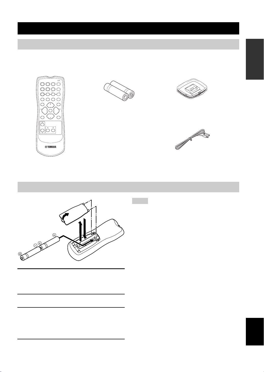
Supplied accessories
Check that you received all of the following parts.
Remote control
DVD
DTV/CBL
VCR
POWER
CD
MD/CD-R
V-AUX
TEST
A/B/C/D/E
5CH STEREO
VOLUME
VOLUME
MULTI CH IN
PRESET
NIGHT
SLEEP
STRAIGHT
MUTE
SET MENU
TUNER
STANDARD
PROG PROG
LEVEL
Batteries (2)
(AA, R06, UM-3)
Installing batteries in the remote control
INTRODUCTION
AM loop antenna
Indoor FM antenna
1
3
4
2
1 Press the tab of the battery compartment
cover and pull it in the direction of the arrow
to open the cover.
2 Remove the cover.
3 Insert the two supplied batteries (AA, R06,
UM-3) according to the polarity markings
(+ and –) on the inside of the battery
compartment.
4 Put the cover back into place.
Notes
• Change all of the batteries if you notice a decrease in the
operation range of the remote control.
• Do not use an old battery together with a new one.
• Do not use different types of batteries (such as alkaline and
manganese batteries) together. Read the packaging carefully as
these different types of batteries may have the same shape and
color.
• If the batteries have leaked, dispose of them immediately. Avoid
touching the leaked material or letting it come into contact with
clothing, etc. Clean the battery compartment thoroughly before
installing new batteries.
• Do not throw away batteries with general house waste; dispose
of them correctly in accordance with your local regulations.
English
3
CONTROLS AND FUNCTIONS
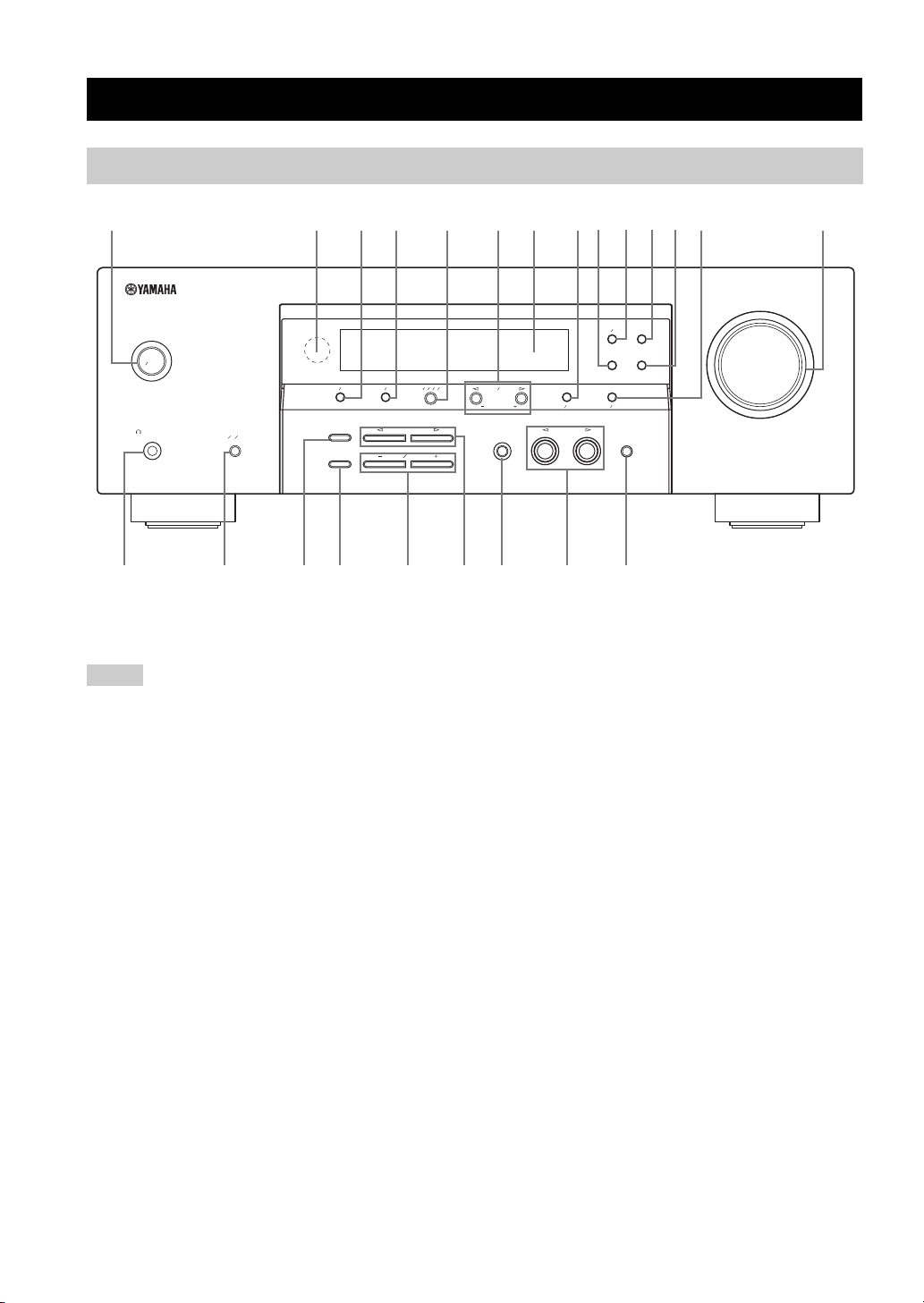
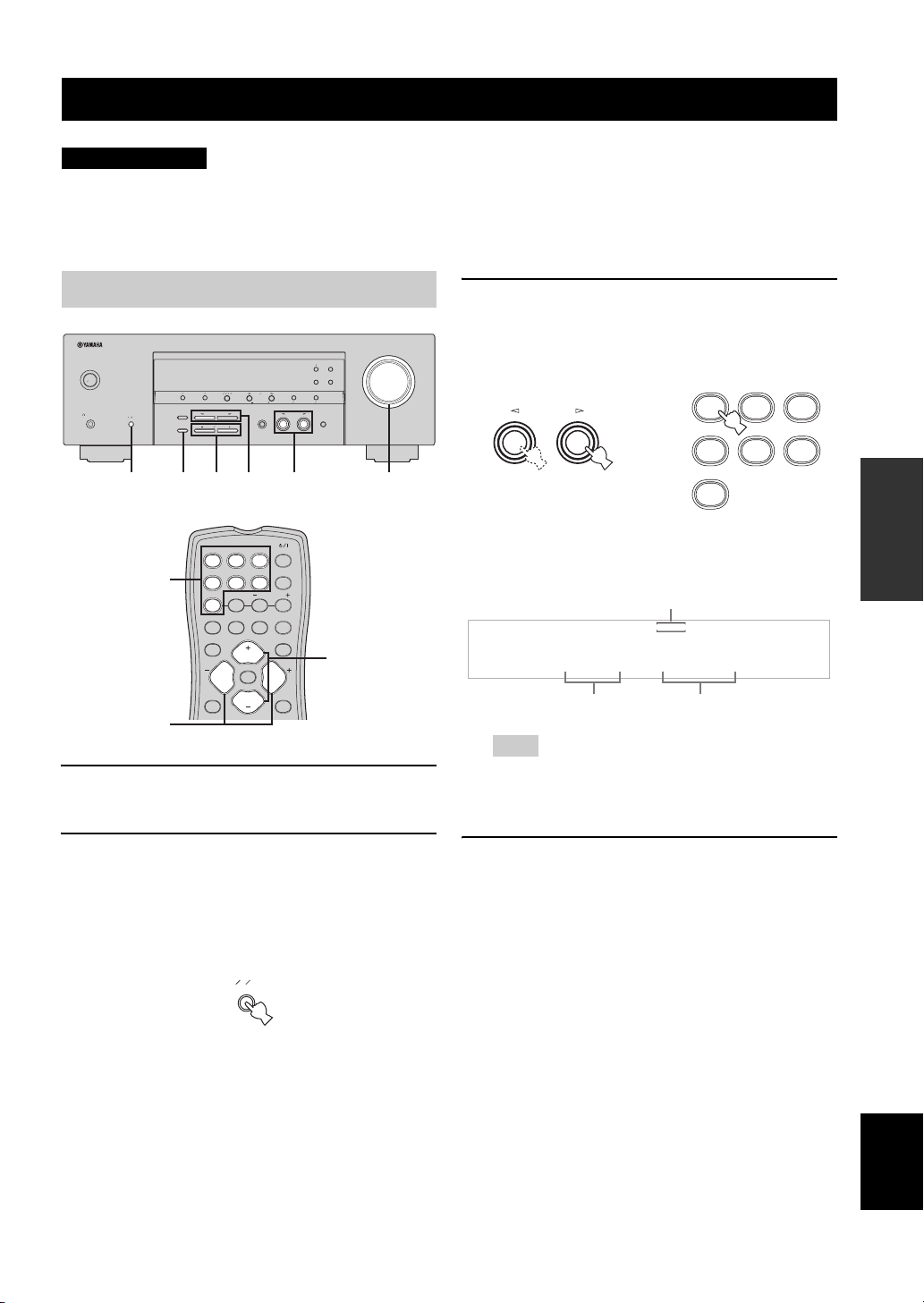
Front panel
CONTROLS AND FUNCTIONS
1
STANDBY
ON
PHONES
SILENT CINEMA
SPEAKERS
ABOFF
234 5 67890ABC D
EON
TEXT
FREQ
PTY SEEK
MODE
START
PRESET
TUNINGFMAM
EDIT
STRAIGHT
EFFECT
TONE CONTROL
BASS
ABCDE
PROGRAM
TREBLE
PRESET
NEXT
TUNING
SET MENU
INPUT MODE
MAN'L
MEMORY
INPUT
TUNING MODE
AUTO FM
AUTO
MAN'L
MULTI CH INPUT
EFGH JIKLM
1 STANDBY/ON
Turns on this unit or sets it to the standby mode.
Notes
• In the standby mode, this unit consumes a small amount of
power in order to receive infrared-signals from the remote
control.
• When you turn on this unit, there will be a 4 to 5-second delay
before this unit can reproduce sound.
2 Remote control sensor
Receives signals from the remote control.
3 PRESET/TUNING
• Switches the function of PRESET/TUNING l / h
between selecting preset station numbers and selecting
the tuning frequency.
• Edits the assignments of present stations.
4 FM/AM
Switches the reception band between FM and AM.
5 A/B/C/D/E
Selects one of the 5 preset station groups (A to E) when
“FM” or “AM” is selected as the input source.
6 PRESET/TUNING l / h
• Selects one of the 8 preset station numbers (1 to 8)
when “FM” or “AM” is selected as the input source.
The colon (:) is displayed in the front panel display.
• Selects the tuning frequency when “FM” or “AM” is
selected as the input source. The colon (:) is not
displayed in the front panel display.
7 Front panel display
Shows information about the operational status of this unit.
8 MEMORY
Stores a preset station in the memory. Hold down this
button for more than 3 seconds to start automatic preset
tuning.
9 PTY SEEK MODE
Sets this unit in the PTY SEEK mode.
0 FREQ/TEXT
Switches the Radio Data System display between the PS
mode, PTY mode, RT mode, CT mode (if the station
offers the corresponding data services) and the frequency
display.
VOLUME
4

CONTROLS AND FUNCTIONS
A EON
Selects a radio program type (NEWS, AFFAIRS, INFO,
or SPORT) for automatic tuning.
B PTY SEEK START
Starts searching for a station once the desired program
type is selected in the PTY SEEK mode.
C TUNING MODE
Switches between automatic tuning (the AUTO indicator
is turned on) and manual tuning (the AUTO indicator is
turned off).
D VOLUME
Controls the output level of all audio channels.
Note
This does not affect the AUDIO OUT (REC) level.
E PHONES jack
Outputs audio signals for private listening with
headphones.
Notes
• When you connect headphones, no signals are output at the
SUBWOOFER OUTPUT jack or at the SPEAKERS terminals.
• All Dolby Digital and DTS audio signals are mixed down to the
left and right headphone channels.
F SPEAKERS
Turns on or off the set of front speakers connected to the A
and/or B terminals on the rear panel.
G STRAIGHT
Turns the sound field programs off or on. When this unit is
in the “STRAIGHT” mode, 2-channel or multi-channel
input signals are output directly from their respective
speakers without effect processing.
H TONE CONTROL
Adjusts the bass/treble balance of the front left and right
speakers in conjunction with BASS/TREBLE +/–.
I BASS/TREBLE +/–
Adjusts the bass/treble balance of the front left and right
speakers in conjunction with TONE CONTROL.
K INPUT MODE
Selects either digital or analog input signals exclusively or
sets this unit to automatically detect the type of input
signals and select the corresponding input signals when
one component is connected via both digital and analog
connections.
L INPUT l / h
Selects the desired input source.
M MULTI CH INPUT
Selects the component connected to the MULTI CH
INPUT jacks as the input source.
Note
The input source connected to the MULTI CH INPUT jacks takes
priority over the source selected with INPUT l / h on the front
panel (or the input selector buttons on the remote control).
INTRODUCTION
J PROGRAM l / h
Selects sound field programs.
English
5

CONTROLS AND FUNCTIONS
Remote control
1
2
3
4
5
6
7
8
9
0
DVD
DTV/CBL
CD
MD/CD-R
TUNER
A/B/C/D/E
STANDARD
5CH STEREO
TEST
PROG PROG
LEVEL
VCR
V-A UX
NIGHT
VOLUME
MUTE
VOLUME
POWER
MULTI CH IN
PRESET
SLEEP
STRAIGHT
SET MENU
A
B
C
D
E
F
G
H
1 Infrared signal transmitter
Outputs infrared control signals. Aim the transmitter at the
component you want to operate.
2 Input selector buttons
Select the input source.
3 A/B/C/D/E
Selects one of the 5 preset station groups (A to E) when
“FM” or “AM” is selected as the input source.
4 STANDARD
Selects the built-in Dolby Pro Logic or Pro Logic II
decoder.
5 5CH STEREO
Selects the “5CH STEREO” sound field program.
6 TEST
Outputs the test tone to adjust the speaker levels.
7 MUTE
Mutes the audio output. Press again to restore the audio
output to the previous volume level.
8 LEVEL
Selects the speaker channel to be adjusted.
9 PROG +/–
Selects sound field programs.
0 Multi control section
Selects and adjusts sound field program parameters or
SET MENU items.
A POWER
Turns on this unit or set it to the standby mode.
B MULTI CH IN
Selects the component connected to the MULTI CH
INPUT jacks as the input source when using an external
decoder, etc.
C PRESET +/–
Selects one of the 8 preset station numbers (1 to 8) when
“FM” or “AM” is selected as the input source.
D SLEEP
Sets the sleep timer.
E NIGHT
Turns on or off the night listening mode.
6
CONTROLS AND FUNCTIONS
F STRAIGHT
Turns the sound field programs off or on. When this unit is
in the “STRAIGHT” mode, 2-channel or multi-channel
input signals are output directly from their respective
speakers without effect processing.
G VOLUME +/–
Controls the output level of all audio channels.
Note
This does not affect the AUDIO OUT (REC) level.
H SET MENU
Enters “SET MENU”.
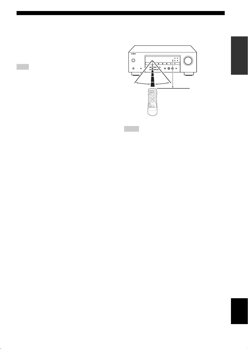
■ Using the remote control
The remote control transmits a directional infrared ray.
Be sure to aim the remote control directly at the remote
control sensor on this unit during operation.
30º 30º
Notes
• Do not spill water or other liquids on the remote control.
• Do not drop the remote control.
• Do not leave or store the remote control in the following types
of conditions:
– places of high humidity, such as near a bath
– places of high temperature, such as near a heater or stove
– places of extremely low temperatures
– dusty places
Approximately 6 m (20 ft)
INTRODUCTION
English
7

CONTROLS AND FUNCTIONS
Front panel display
1 32 4 756 8 9
VIRTUAL
DIGITAL
PL
PCM
STANDARD NIGHT
PL
VCR
SILENT CINEMA
V-A UX
SP
AB
DTV/CBL
HiFi DSP
DVD
MD/CD-R
AUTO
PTY
HOLD PS
TUNER CD
TUNED
STEREO
PTYRTCT EON
MEMORY
SLEEP
dB
MUTE
ft
LFE SL SR
VOLUME
dB
LCR
0ABCEDF JIK
1 Decoder indicators
The respective indicator lights up when any of the
decoders of this unit function.
2 VIRTUAL indicator
Lights up when Virtual CINEMA DSP is active.
3 SILENT CINEMA indicator
Lights up when headphones are connected and a sound
field program is selected.
4 Input source indicators
A corresponding cursor lights up to show the currently
selected input source.
5 AUTO indicator
Lights up when this unit is in the automatic tuning mode.
6 TUNED indicator
Lights up when this unit is tuned into a station.
7 STEREO indicator
Lights up when this unit is receiving a strong signal for an
FM stereo broadcast while the AUTO indicator is lit.
8 MUTE indicator
Flashes while the MUTE function is on.
9 VOLUME level indicator
Indicates the current volume level.
0 PCM indicator
Lights up when this unit is reproducing PCM (Pulse Code
Modulation) digital audio signals.
G
H
E CINEMA DSP indicator
Lights up when you select a CINEMA DSP program.
F HiFi DSP indicator
Lights up when you select a HiFi DSP program.
G Multi-information display
Shows the name of the current program and other
information when adjusting or changing settings.
H Radio Data System indicators
(U.K. and Europe models only)
Lights up when the Radio Data System data is being
received.
EON
Lights up when the EON data service is being
received.
PTY HOLD
Lights up while searching for the Radio Data System
stations in the PTY SEEK mode.
I SLEEP indicator
Lights up while the sleep timer is on.
J MEMORY indicator
Flashes to show that a station can be stored.
K Input channel indicators
Indicate the channel components of the current digital
input signal.
A STANDARD indicator
Lights up when the “STANDARD” program is selected.
B NIGHT indicator
Lights up when you select a night listening mode.
C Speaker indicators
Light up according to the set of front speakers selected.
D Headphones indicator
Lights up when headphones are connected.
8
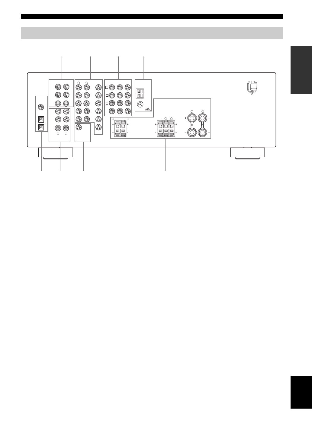
Rear panel
CONTROLS AND FUNCTIONS
1234
AUDIO
VIDEO
R
L
DVD
DTV/
OUTPUT
WOOFER
CBL
V-AUX
VCR
OUT
SUB
CENTER
L
COMPONENT VIDEO
PBYPR
DV
D
A
DTV/
CBL
B
VCR
C
IN
MONITOR OUT
R
L
SURROUND
MONITOR
OUT
DVD
COAXIAL
OPTICAL
DTV/CBL
DVD
DIGITAL
INPUT
MULTI CH INPUT
FRONT
SURROUND
SUB
WOOFER
3
CD
2
IN
(PLAY)
MD/
CD-R
1
OUT
(REC)
R
AUDIO
56 7 8
1 MULTI CH INPUT jacks
See page 16 for connection information.
2 Video component jacks
See page 14 for connection information.
3 COMPONENT VIDEO jacks
See page 16 for connection information.
4 Antenna terminals
See page 18 for connection information.
TUNER
INTRODUCTION
AM
ANT
GND
FM
ANT
CENTER
SPEAKERS
A
R
L
T
B
FRONT
R
L
FRON
5 DIGITAL INPUT jacks
See pages 14 and 15 for connection information.
6 Audio component jacks
See page 17 for connection information.
7 SUBWOOFER OUTPUT jack
See page 12 for connection information.
8 SPEAKERS terminals
See page 11 for connection information.
English
9
CONNECTIONS
CONNECTIONS
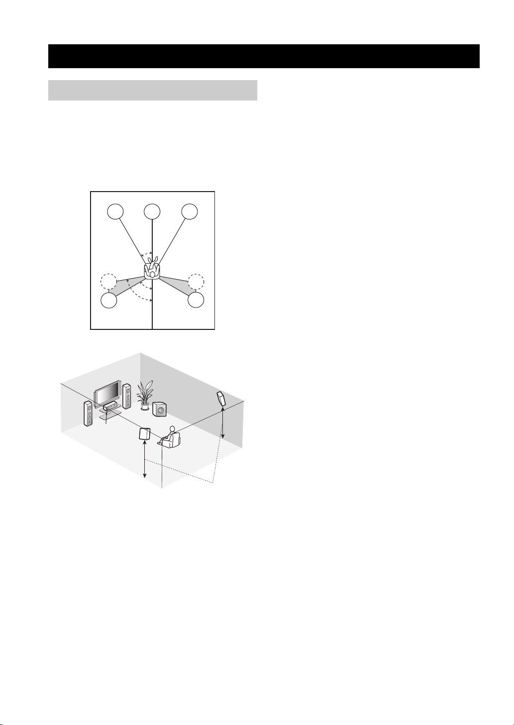
Placing speakers
The speaker layout below shows the standard ITU-R*
speaker setting. You can use it to enjoy CINEMA DSP and
multi-channel audio sources.
*
ITU-R is the radio communication sector of the ITU
(International Telecommunication Union).
FL
SL
SL
FL
C
FR
80˚
SL
C
30˚
60˚
SW
FR
SR
SR
SR
■ Front speakers (FL and FR)
The front speakers are used for the main source sound plus
effect sounds. Place these speakers an equal distance from
the ideal listening position. The distance of each speaker
from each side of the video monitor should be the same.
■ Center speaker (C)
The center speaker is for the center channel sounds
(dialog, vocals, etc.). If for some reason it is not practical
to use a center speaker, you can do without it. Best results,
however, are obtained with the full system. Place the
center speaker centrally between the front speakers and as
close to the monitor as possible, such as directly over or
under it.
■ Surround speakers (SL and SR)
The surround speakers are used for effect and surround
sounds. Place these speakers behind your listening
position, facing slightly inwards, about 1.8 m (6 ft) above
the floor.
■ Subwoofer (SW)
The use of a subwoofer, such as the YAMAHA Active
Servo Processing Subwoofer System, is effective not only
for reinforcing bass frequencies from any or all channels,
but also for high fidelity reproduction of the LFE (lowfrequency effect) channel included in Dolby Digital and
DTS software. The position of the subwoofer is not so
critical, because low bass sounds are not highly
directional. But it is better to place the subwoofer near the
front speakers. Turn it slightly toward the center of the
room to reduce wall reflections.
10
1.8 m (6 ft)

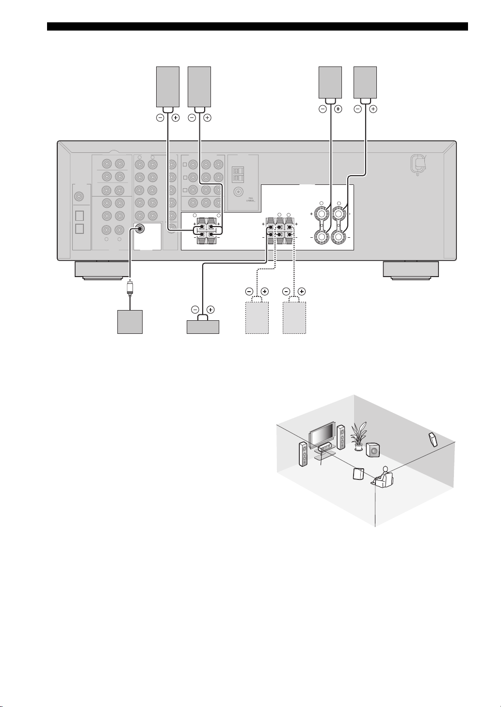
Connecting speakers
Be sure to connect the left channel (L), right channel (R),
“+” (red) and “–” (black) properly. If the connections are
faulty, no sound will be heard from the speakers, and if the
polarity of the speaker connections is incorrect, the sound
will be unnatural and lack bass.
CAUTION
• Use speakers with the specified impedance
shown on the rear panel of this unit.
• Before connecting the speakers, make sure
that this unit is turned off.
• Do not let the bare speaker wires touch each
other or do not let them touch any metal part
of this unit. This could damage this unit and/or
speakers.
• Use magnetically shielded speakers. If this
type of speakers still creates the interference
with the monitor, place the speakers away
from the monitor.
■ Before connecting to the SPEAKERS
terminal
A speaker cord is actually a pair of insulated cables
running side by side. Cables are colored or shaped
differently, perhaps with a stripe, groove or ridges.
Connect the striped (grooved, etc.) cable to the “+” (red)
terminals of this unit and your speaker. Connect the plain
cable to the “–” (black) terminals.
Remove approximately 10 mm (3/8”) of insulation
from the end of each speaker cable and then
twist the bare wires of the cable together to
prevent short circuits.
10 mm (3/8”)
CONNECTIONS
■ Connecting to the FRONT A SPEAKERS
terminals
2
1
Red: positive (+)
Black: negative (–)
3
1 Loosen the knob.
2 Insert the bare end of the speaker wire into
the hole on the terminal.
3 Tighten the knob to secure the wire.
Connecting the banana plug
(except U.K., Europe, Korea and Asia models)
The banana plug is a single-pole electrical connector
widely used to terminate speaker cables.
First, tighten the knob and then insert the banana plug
connector into the end of the corresponding terminal.
Banana plug
■ Connecting to the FRONT B, CENTER,
and SURROUND SPEAKERS terminals
1
3
Red: positive (+)
Black: negative (–)
PREPARATION
2
1 Press down the tab.
2 Insert the bare end of the speaker wire into
the hole on the terminal.
3 Release the tab to secure the wire.
English
11
CONNECTIONS
DIGITAL
DVD
COAXIA
OPTICAL
DTV-CBL
DVD
Surround speakers
4
MULTI CH INPUT
FRONT
SURROUND
SUB
INPUT
WOOFER
3
L
CD
2
IN
(PLAY)
MD/
CD-R
1
OUT
(REC)
R
AUDIO
AUDIO
R
L
DVD
DTV/
OUTPUT
WOOFER
CBL
V-AUX
IN
VCR
OUT
SUB
CENTER
L
6
Subwoofer Center
VIDEO
MONITOR
OUT
LeftRight
COMPONENT VIDEO
D
DV
A
DTV/
CBL
B
VCR
C
MONITOR OUT
R
speaker
5
PBYPR
SURROUND
TUNER
AM
ANT
GND
FM
ANT
R
L
CENTER
31 2
Front speakers (B)
FRONT
B
L
LeftRight
Front speakers (A)
1
SPEAKERS
A
R
L
T
FRON
LeftRight
2
■ FRONT terminals
Connect one or two speaker systems (1, 2) to these
terminals. If you use only one front speaker system,
connect it to the FRONT A terminals.
■ CENTER terminals
Connect a center speaker (3) to these terminals.
■ SURROUND terminals
Connect surround speakers (4, 5) to these terminals.
■ SUBWOOFER OUTPUT jack
Connect a subwoofer with built-in amplifier (6) (such as
the YAMAHA Active Servo Processing Subwoofer
System) to this jack.
1
6
2
4
3
5
Speaker layout
12
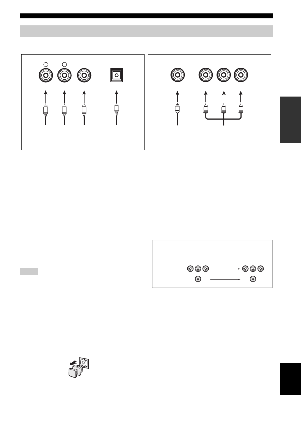
Information on jacks and cable plugs
Audio jacks and cable plugs Video jacks and cable plugs
CONNECTIONS
AUDIO
L
L
Left and right
analog audio
cable plugs
R
(Red)(White) (Orange) (Yellow) (Green) (Blue) (Red)
R
DIGITAL AUDIO
COAXIAL
C
Coaxial
digital audio
cable plug
DIGITAL AUDIO
OPTICAL
O
Optical
digital
audio cable
plug
■ Audio jacks
This unit has three types of audio jacks (analog audio,
digital audio coaxial, and digital audio optical).
Connection depends on the availability of audio jacks on
your other components.
AUDIO jacks
For conventional analog audio signals transmitted via left
and right analog audio cables. Connect red plugs to the
right jacks and white plugs to the left jacks.
DIGITAL AUDIO COAXIAL jacks
For digital audio signals transmitted via coaxial digital
audio cables.
DIGITAL AUDIO OPTICAL jacks
For digital audio signals transmitted via optical digital
audio cables.
Notes
• You can use the digital jacks to input PCM, Dolby Digital and
DTS bitstreams. When you connect components to both the
COAXIAL and OPTICAL jacks, priority is given to the signals
input at the COAXIAL jack. All digital input jacks are
compatible with 96 kHz sampling digital signals.
• This unit handles digital and analog signals independently. Thus
audio signals input at the analog jacks are output only at the
analog AUDIO OUT (REC) jacks.
• Pull out the cap from the optical jack before you connect the
fiber optic cable. Do not discard the cap. When you are not
using the optical jack, be sure to put the cap back in place. This
cap protects the jack from dust.
VIDEO
V
Composite
video cable
plug
COMPONENT VIDEO
Y PB PR
Y
PB
Component
video cable
plugs
PR
■ Video jacks
This unit has two types of video jacks (composite video,
and component video). Connection depends on the
availability of input jacks on your video monitor.
VIDEO jacks
For conventional composite video signals transmitted via
composite video cables.
COMPONENT VIDEO jacks
For component signals, separated into the luminance (Y)
and chrominance (P
separate wires of component video cables.
Video signal flow for MONITOR OUT
COMPONENT
VIDEO
VIDEO
B, PR) video signals transmitted on
Input
Output
(MONITOR OUT)
PREPARATION
13
English
CONNECTIONS
R
Connecting video components
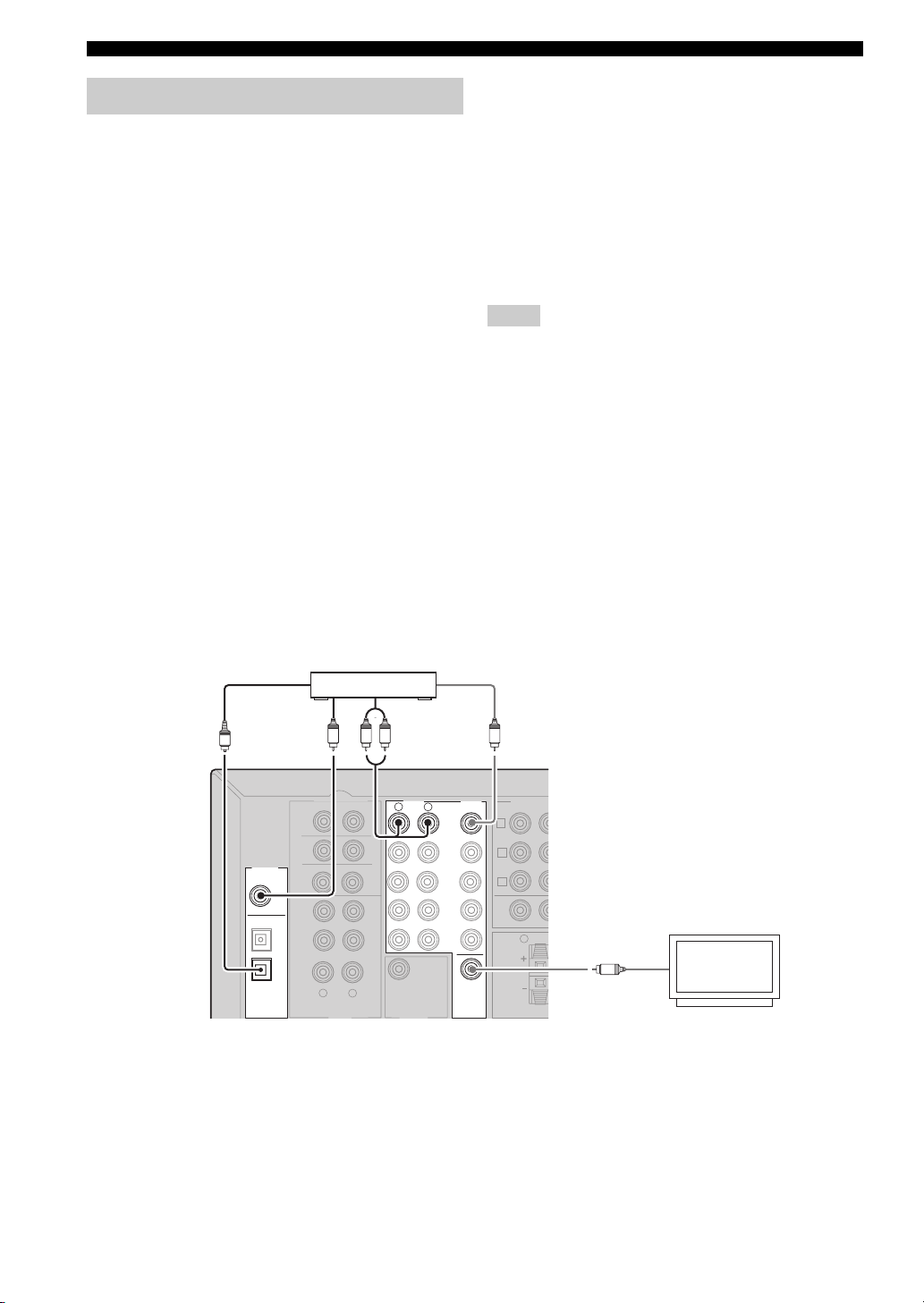
■ Connecting a video monitor
Connect the video input jack of your video monitor to the
MONITOR OUT jack.
■ Connecting a DVD player/cable TV/
satellite tuner
Connect the coaxial digital audio signal output jack of
your DVD player to the DIGITAL INPUT DVD
COAXIAL jack and connect the video signal output jack
of the component to the DVD VIDEO jack of this unit.
Connect the optical digital audio signal output jack of
your cable TV or satellite tuner to the DIGITAL INPUT
DTV/CBL jack and connect the video signal output jack
of the component to the DTV/CBL VIDEO jack of this
unit.
y
• Use the AUDIO jacks of this unit for a video component which
does not have optical digital output jack. To enjoy the surround
sound, use the sound field program selector buttons on the
remote control (see page 30).
• If your DVD player does not have a coaxial digital output jack
but has an optical cable, connect the jack to the DIGITAL
INPUT DVD OPTICAL.
• You can also connect a video monitor, DVD player, digital TV,
and cable TV to this unit using the COMPONENT VIDEO
connections (see page 16).
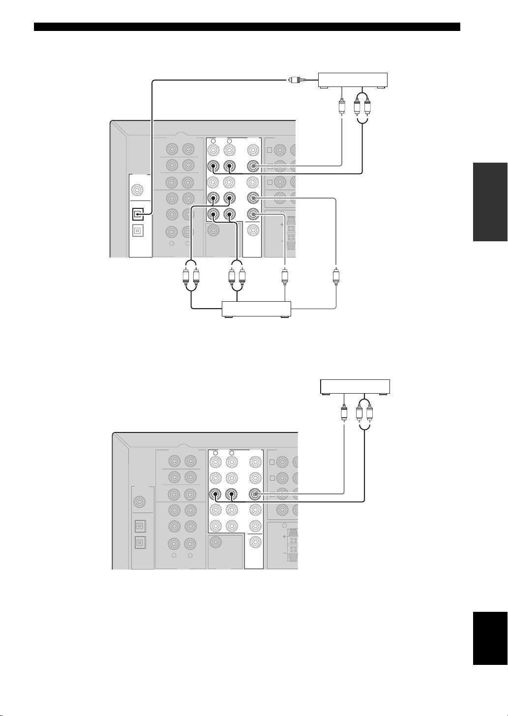
■ Connecting a DVD recorder/VCR
Connect the audio signal input jacks of your video
component to the VCR AUDIO OUT jacks of this unit.
Then connect the video signal input jack of the video
component to the VCR VIDEO OUT jack of this unit for
picture recording.
Connect the audio signal output jacks of your component to
the VCR AUDIO IN jacks of this unit. Then connect the
video signal output jack of the component to the VCR
VIDEO IN jack of this unit to play a source from your
recording component.
Notes
• Once you have connected a recording component to this unit,
keep the component turned on while using this unit. If the
power is turned off, this unit may distort the sound from other
components.
• Be sure to connect your video source components in the same
way you connect your video monitor to this unit. For example,
if you connect your video monitor to this unit using a VIDEO
connection, connect your video source components to this unit
using the VIDEO connections.
■ Connecting another video component
Connect the video signal output jack of your component to
the V-AUX VIDEO jack of this unit.
Connect the audio signal output jacks of the component to
the V-AUX AUDIO jacks of this unit.
O
Audio out
Audio
DIGITAL
INPUT
3
DVD
COAXIA
L
OPTICAL
DTV/CBL
2
DVD
1
FRONT
SURROUND
SUB
WOOFER
CD
IN
(PLAY)
MD/
CD-R
OUT
(REC)
out
MULTI CH INPUT
R
DVD player
L R
CENTER
L
Audio
out
AUDIO
R
WOOFER
Video out
L
DVD
DTV/
CBL
V-AUX
VCR
OUT
SUB
VC
VIDEO
COMPONEN
PY
DV
D
A
DTV/
CBL
B
VCR
C
IN
MONITOR OUT
R
SUR
Video in
MONITOR
OUT
V
Video monitor
14
R
Audio out
R
O
Cable TV or
Satellite tuner
Video
out
V
L R
Audio
out
CONNECTIONS
DIGITAL
INPUT
DVD
COAXIA
OPTICAL
DTV/CBL
DVD
CENTER
AUDIO
R
SUB
WOOFER
VIDEO
MONITOR
OUT
COMPONEN
DV
D
A
DTV/
CBL
B
VCR
C
MONITOR OUT
PY
PREPARATION
R
SUR
L
DVD
DTV/
CBL
V-AUX
IN
VCR
OUT
VV
MULTI CH INPUT
FRONT
SURROUND
SUB
WOOFER
3
L
CD
2
IN
(PLAY)
MD/
CD-R
1
OUT
(REC)
R
L
LR LR
Audio inAudio out Video outVideo in
DVD recorder or
VCR
Another video
component
L R
Audio
out
Vid eo
out
V
DIGITAL
DVD
COAXIA
OPTICAL
DTV/CBL
DVD
INPUT
CENTER
AUDIO
R
SUB
WOOFER
VIDEO
MONITOR
OUT
COMPONEN
D
DV
A
DTV/
CBL
B
VCR
C
MONITOR OUT
PY
R
SUR
L
DVD
DTV/
CBL
V-AUX
IN
VCR
OUT
MULTI CH INPUT
FRONT
SURROUND
SUB
WOOFER
3
L
CD
2
IN
(PLAY)
MD/
CD-R
1
OUT
(REC)
R
L
English
15
CONNECTIONS
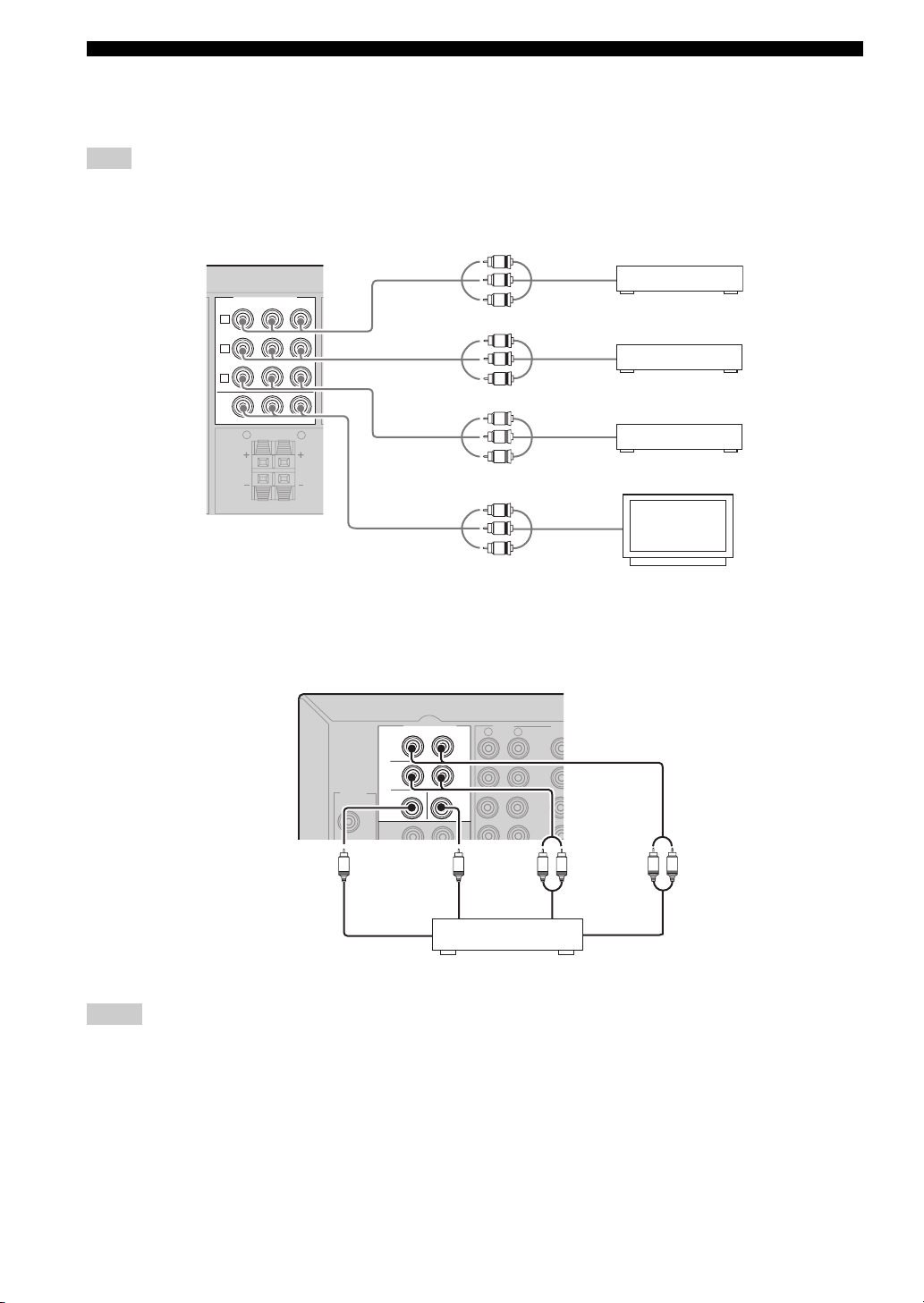
E
■ Connecting to the COMPONENT VIDEO jacks
You can enjoy high-quality pictures by connecting your video monitor and video source components to this unit using
COMPONENT VIDEO connections.
Note
Be sure to connect your video source components in the same way you connect your video monitor to this unit. For example, if you
connect your video monitor to this unit using a COMPONENT VIDEO connection, connect your video source components to this unit
using the COMPONENT VIDEO connection.
DVD player
Cable TV or
satellite tuner
DVD recorder or
VCR
Video monitor
COMPONENT VIDEO
D
DV
A
DTV/
CBL
B
VCR
C
MONITOR OUT
R
PBYPR
SURROUND
Y
P
B
P
R
Y
P
B
P
R
L
Y
P
B
P
R
Video out
Video out
Video out
Y
P
B
P
R
Video in
■ Connecting to the MULTI CH INPUT jacks
This unit is equipped with 6 additional input jacks (FRONT L/R, CENTER, SURROUND L/R and SUBWOOFER) for
discrete multi-channel input from a multi-format player, external decoder or sound processor. Connect the output jacks
on your multi-format player or external decoder to the MULTI CH INPUT jacks. Be sure to match the left and right
output jacks to the left and right input jacks for the front and surround channels.
MULTI CH INPUT
FRONT
SURROUND
DIGITAL
SUB
INPUT
WOOFER
3
DVD
Subwoofer out Front out
Notes
• When you select the component connected to the MULTI CH INPUT jacks as the input source (see page 25), this unit automatically
turns off the digital sound field processor, and you cannot select sound field programs.
• This unit does not redirect signals input at the MULTI CH INPUT jacks to accommodate for missing speakers. We recommend that
you connect a 5.1-channel speaker system before using this feature.
• When headphones are used, signals are output only from the front left and right channels.
AUDIO
R
CENTER
Multi-format player or
external decoder
VID
L
DVD
DTV/
CBL
V-AUX
IN
LR
LR
Surround outCenter out
16
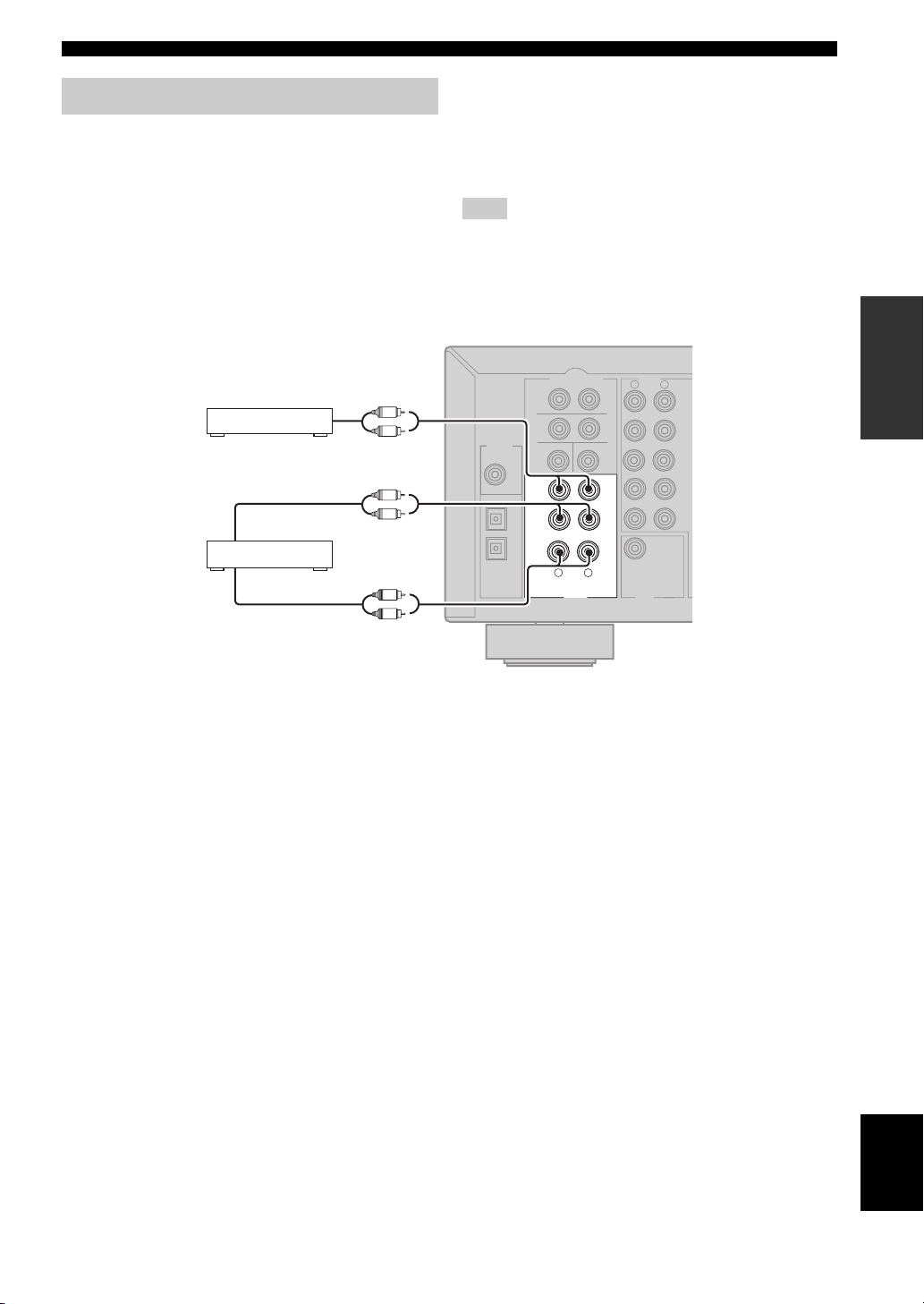
Connecting audio components
/
T
X
■ Connecting a CD player
Connect the output jacks of your CD player to the CD
jacks of this unit.
y
To make a digital connection to a CD player, select the
corresponding setting for DIGITAL INPUT jacks in “INPUT
ASSIGN” (see page 47).
CONNECTIONS
■ Connecting a CD recorder/MD recorder
Connect the input jacks of your CD recorder or MD
recorder to the MD/CD-R OUT (REC) jacks.
Connect the output jacks of your CD recorder or MD
recorder to the MD/CD-R IN (PLAY) jacks to play a
source from your recording component.
Note
Once you have connected a recording component to this unit,
keep the component turned on while using this unit. If the
component is turned off, this unit may distort the sound from
other components.
PREPARATION
CD player
CD recorder or
MD recorder
Audio out
L
R
Audio out
L
R
Audio in
L
R
DIGITAL
INPUT
DVD
COAXIA
OPTICAL
DTV-CBL
DVD
MULTI CH INPUT
FRONT
SURROUND
SUB
WOOFER
3
L
CD
2
IN
(PLAY)
MD/
CD-R
1
OUT
(REC)
R
AUDIO
AUDIO
R
L
DVD
DTV
OUTPUT
SUB
WOOFER
CBL
V-AU
IN
VCR
OU
CENTER
L
English
17
CONNECTIONS
AM
ANT
GND
FM
ANT
TUNER
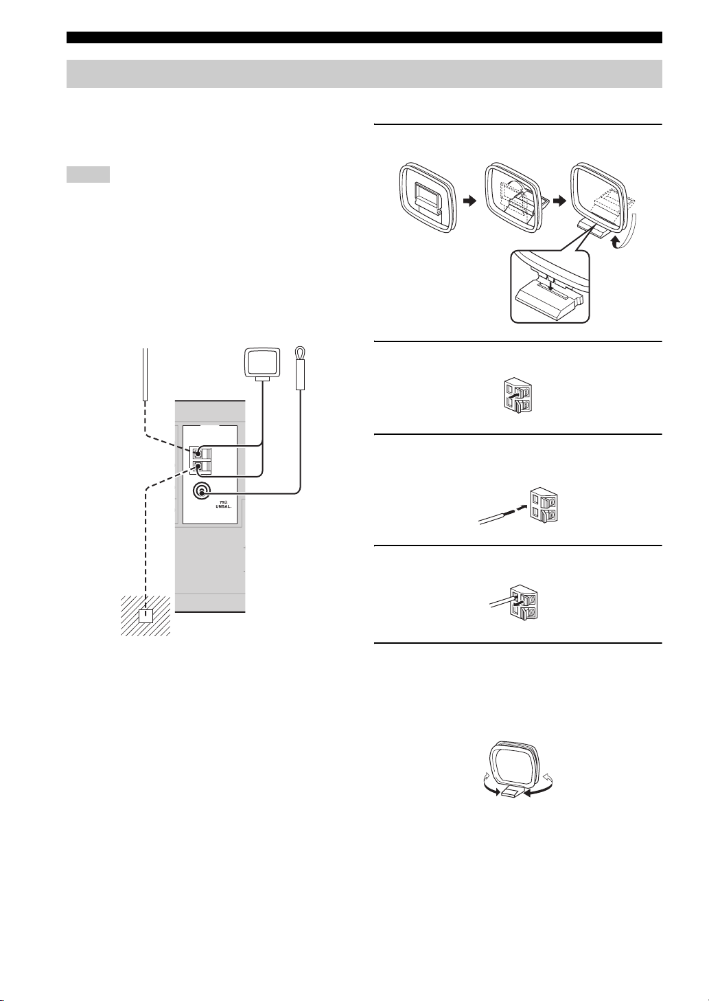
Connecting the FM and AM antennas
Both FM and AM indoor antennas are supplied with this
unit. In general, these antennas should provide sufficient
signal strength. Connect each antenna correctly to the
designated terminals.
Notes
• The AM loop antenna should be placed away from this unit.
• A properly installed outdoor antenna provides clearer reception
than an indoor one. If you experience poor reception quality,
install an outdoor antenna. Consult the nearest authorized
YAMAHA dealer or service center about outdoor antennas.
• The AM loop antenna should always be connected, even if an
outdoor AM antenna is connected to this unit.
Outdoor AM antenna
Use a 5 to 10 m (16 to 32 ft) of
vinyl-covered wire extended
outdoors from a window.
AM loop
antenna
(supplied)
Indoor FM
antenna
(supplied)
■ Connecting the AM loop antenna
1 Set up the AM loop antenna.
2 Press down the tab of the AM ANT terminal.
3 Insert the one of the AM loop antenna lead
wires into the AM ANT terminal.
4 Release the tab back to secure the wire.
Ground
For maximum safety and minimum
interference, connect the antenna GND
terminal to a good earth ground. A good
earth ground is a metal stake driven into
moist earth.
5 Repeat steps 2 through 4 to connect the
other lead wire to the GND terminal.
Once you have properly connected the AM loop
antenna to this unit, orient the AM loop antenna for
the best reception when you tune into AM stations.
18

CONNECTIONS
Connecting the power cable
Once all connections are complete, plug the power cable
into the AC wall outlet.
Power cable
Turning on the power
When all connections are complete, turn on this unit.
STANDBY/ON
VOLUME
SILENT CINEMA
EON
TEXT
FREQ
PTY SEEK
MODE
STANDBY
ON
PHONES
SPEAKERS
ABOFF
PRESET
TUNINGFMAM
EDIT
STRAIGHT
EFFECT
TONE CONTROL
DVD
DTV/CBL
CD
MD/CD-R
TUNER
A/B/C/D/E
STANDARD
TEST
PROG PROG
LEVEL
ABCDE
PROGRAM
TREBLE
BASS
5CH STEREO
VOLUME
MUTE
VOLUME
V-AUX
NIGHT
NEXT
VCR
PRESET
STRAIGHT
PRESET
SET MENU
INPUT MODE
POWER
MULTI CH IN
SLEEP
SET MENU
TUNING
MEMORY
MAN'L
AUTO FM
INPUT
POWER
START
TUNING MODE
AUTO
MAN'L
MULTI CH INPUT
PREPARATION
Press STANDBY/ON on the front panel (or
POWER on the remote control) to turn on this
unit.
STANDBY
ON
or
Front panel Remote control
POWER
Press STANDBY/ON on the front panel (or POWER on
the remote control) again to set this unit to the standby
mode.
Memory back-up
The memory back-up circuit prevents the stored data
from being lost even if this unit is in the standby mode.
However, the stored data will be lost in case the power
cable is disconnected from the AC wall outlet or if the
power supply is cut off for more than one week.
English
19
SETUP
SETUP
The “BASIC MENU” feature is a useful way to set up
your system quickly and with minimal effort.
y
• If you wish to configure this unit manually using more precise
adjustments, use the detailed parameters in “SOUND MENU”
(see page 45).
• Altering any parameters in “SETUP” resets all parameters
manually adjusted in “SOUND MENU” (see page 45).
• Initial settings are indicated in bold under each parameter.
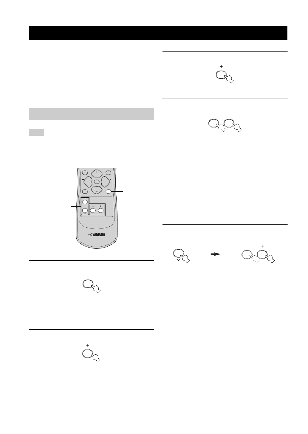
Using BASIC MENU
3 Press + to enter “1 SETUP”.
“ROOM” appears in the front panel display.
4 Press +/– to select the desired setting.
Note
Before you begin:
• Press SPEAKERS on the front panel repeatedly to select the
front speakers you want to use.
• Make sure you disconnect your headphones from this unit.
TEST
PROG PROG
LEVEL
VOLUME
MUTE
VOLUME
STRAIGHT
SET MENU
1
2-15
1 Press SET MENU.
SET MENU
“BASIC MENU” appears in the front panel display.
If the front panel display shows anything other than
“BASIC MENU”, press SET MENU repeatedly until
“BASIC MENU” appears.
Select the size of the room where you have installed
your speakers. In general, the room sizes are defined
as follows:
Choices: S, M, L
[U.S.A. and Canada models]
2
S (small) 16 x 13 ft, 200 ft
M (medium) 20 x 16 ft, 300 ft
L (large) 26 x 19 ft, 450 ft
(4.8 x 4.0 m, 20 m2)
2
(6.3 x 5.0 m, 30 m2)
2
(7.9 x 5.8 m, 45 m2)
[Other models]
S (small) 3.6 x 2.8 m, 10 m
M (medium) 4.8 x 4.0 m, 20 m
L (large) 6.3 x 5.0 m, 30 m
2
2
2
5 Press d to enter “SUBWOOFER” and then
press +/– to select the desired setting.
Choices: YES, NONE
• Select “YES” if you have a subwoofer in your
system.
• Select “NONE” if you do not have a subwoofer in
your system.
2 Press + to enter “BASIC MENU”.
“1 SETUP” appears in the front panel display.
20
SETUP
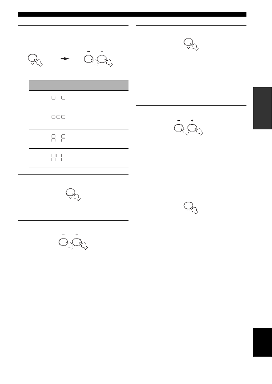
6 Press d to confirm your selection and then
press +/– to select the number of speakers
connected to this unit.
Choice Display Speakers
2spk
3spk
4spk
5spk
LL C R
SL SB SR
LL CR
SL SB SR
LL C R
SL SB SR
LL C R
SL SBSBSR
Front L/R
Front L/R, Center
Front L/R, Surround L/R
Front L/R, Center, Surround L/R
7 Press d to confirm your selection.
9 Press d to confirm your selection.
If you selected “SET” in the previous step, you will
hear a test tone from each speaker in turn.
“CHECK:TestTone” appears in the front panel
display for a few seconds and then “CHECK OK?”
appears in the front panel display.
y
The indicator of the speaker currently outputting the test
tone flashes in the front panel display.
10 Press +/– to select the desired setting.
Choices: YES, NO
• Select “YES” to complete the setup procedure if
the test tone levels from each speaker were
satisfactory.
• Select “NO” to proceed to the speaker level
adjustment menu to balance the output level of
each speaker.
PREPARATION
“iSET CANCEL” appears in front panel display.
8 Press +/– to select the desired setting.
Choices: SET, CANCEL
• Select “SET” to apply the settings you made.
• Select “CANCEL” to cancel the setup procedure
without making any changes.
y
You can also press SET MENU repeatedly to cancel the
setup procedure.
11 Press d to confirm your selection.
• If you selected “YES” in the previous step, the
setup procedure is completed and the display
returns to the “BASIC MENU”.
• If you selected “NO” in the previous step, the
speaker level adjustment display appears in the
front panel display.
English
21
SETUP
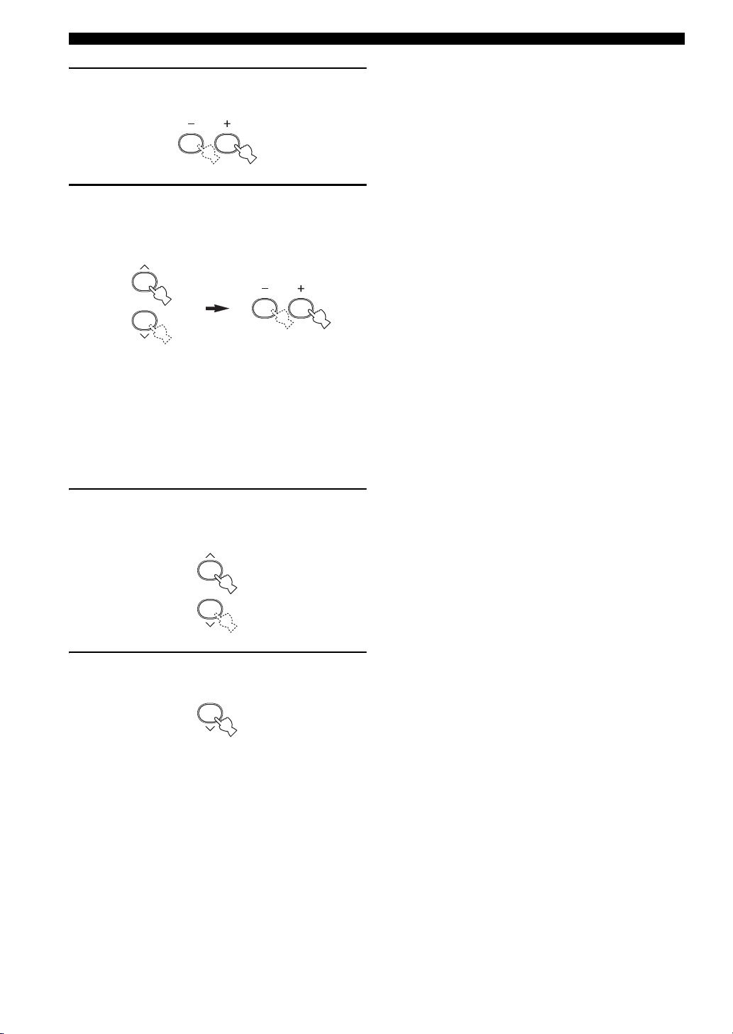
12 Press +/– to adjust the balance between the
front left and right speakers.
13 Press d / u to select a speaker and then +/–
to adjust the balance.
Press + to increase the value.
Press – to decrease the value.
• Select “C” to adjust the balance between the front
left and center speakers.
• Select “SL” to adjust the balance between the front
left and surround left speakers.
• Select “SR” to adjust the balance between the
surround left and surround right speakers.
• Select “SWFR” to adjust the balance between the
front left speaker and the subwoofer.
14 To confirm the settings, press d / u
repeatedly until “2 SP LEVEL” appears in the
front panel display.
15 Press d repeatedly until the menu
disappears.
22
PLAYBACK
PLAYBACK
CAUTION
Extreme caution should be exercised when you play back CDs encoded in DTS. If you play back a CD
encoded in DTS on a DTS-incompatible CD player, you will only hear some unwanted noise that may
damage your speakers. Check whether your CD player supports CDs encoded in DTS. Also, check the
sound output level of your CD player before you play back a CD encoded in DTS.
Basic operations
EON
TEXT
FREQ
PTY SEEK
MODE
MEMORY
MAN'L
INPUT
SLEEP
SET MENU
START
TUNING MODE
AUTO FM
AUTO
MAN'L
MULTI CH INPUT
SILENT CINEMA
STANDBY
ON
PHONES
PRESET
TUNINGFMAM
EDIT
SPEAKERS
STRAIGHT
ABOFF
TONE CONTROL
EFFECT
3
PROG PROG
PROGRAM
BASS
DVD
CD
TUNER
STANDARD
TEST
LEVEL
ABCDE
TREBLE
DTV/CBL
MD/CD-R
A/B/C/D/E
5CH STEREO
NEXT
VOLUME
MUTE
VOLUME
V-AUX
NIGHT
PRESET
INPUT MODE
VCR
TUNING
SET MENU
PRESET
POWER
MULTI CH IN
STRAIGHT
7
1 Turn on the video monitor connected to this
unit.
VOLUME
537662
5
3 Press INPUT l / h on the front panel
repeatedly (or press one of the input selector
buttons on the remote control) to select the
desired input source.
DVD
DTV/CBL
INPUT
CD
or
MD/CD-R
TUNER
Front panel
Remote control
The name of the currently selected input source
appears in the front panel display for a few seconds.
Selected input source
VCR
V-AU X
DTV/CBL
DVD
MD/CD-R
TUNER CD
DVD AUTO
Selected input source Input mode
Note
If you are to select an input source connected via digital
connections, set “INPUT MODE” to “AUTO” or “DTS”
(see page 26).
VCR
V-A UX
OPERATION
BASIC
2 Press SPEAKERS on the front panel
repeatedly to select the front speakers you
want to use.
The respective speaker indicators lights up in the
front panel display.
SPEAKERS
ABOFF
4 Start playback on the selected component or
select a broadcast station.
• When a multi-channel signal (Dolby Digital or
DTS) is input digitally, this unit decodes the signal
and reproduces surround sound.
• Refer to the operating instructions for the source
component.
• See page 35 for details about FM/AM tuning
instructions.
English
23
PLAYBACK
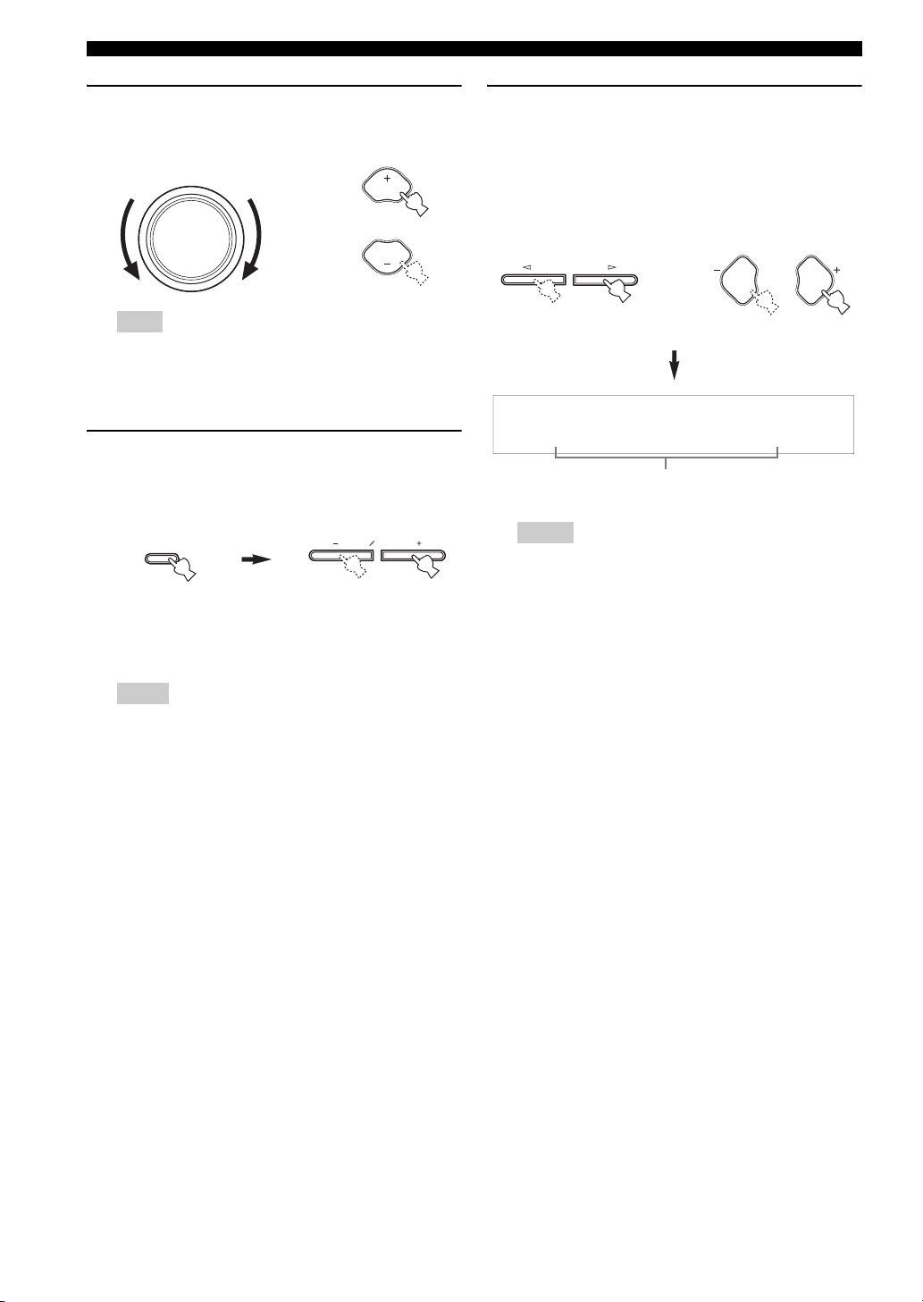
5 Rotate VOLUME on the front panel (or press
VOLUME +/– on the remote control) to adjust
the volume to the desired output level.
VOLUME
or
VOLUME
VOLUME
Note
If you connected a recording component to the VCR OUT,
or MD/CD-R OUT (REC) jacks, and you notice distortion
or low volume during playback from other components, try
turning on the recording component.
6 Press TONE CONTROL on the front panel
repeatedly to select “BASS” or “TREBLE”
and then press BASS/TREBLE +/– to adjust
the corresponding frequency response level.
TREBLE
TONE CONTROL
• Select “BASS” to adjust the low-frequency
response.
• Select “TREBLE” to adjust the high-frequency
response.
Notes
• Speaker and headphone adjustments are stored
independently.
• When “TONE BYPASS” (see page 47) is set to “AUTO”,
and “BASS” and “TREBLE” are set to 0 dB, audio output
automatically bypasses the tone control circuitry of this
unit.
• If you increase or decrease the high-frequency or low-
frequency sound to an extreme level, the tonal quality of
the surround speakers may not match that of the front left
and right speakers.
• TONE CONTROL is not effective when the component
connected to the MULTI CH INPUT jacks is selected as
the input source (see page 25).
BASS
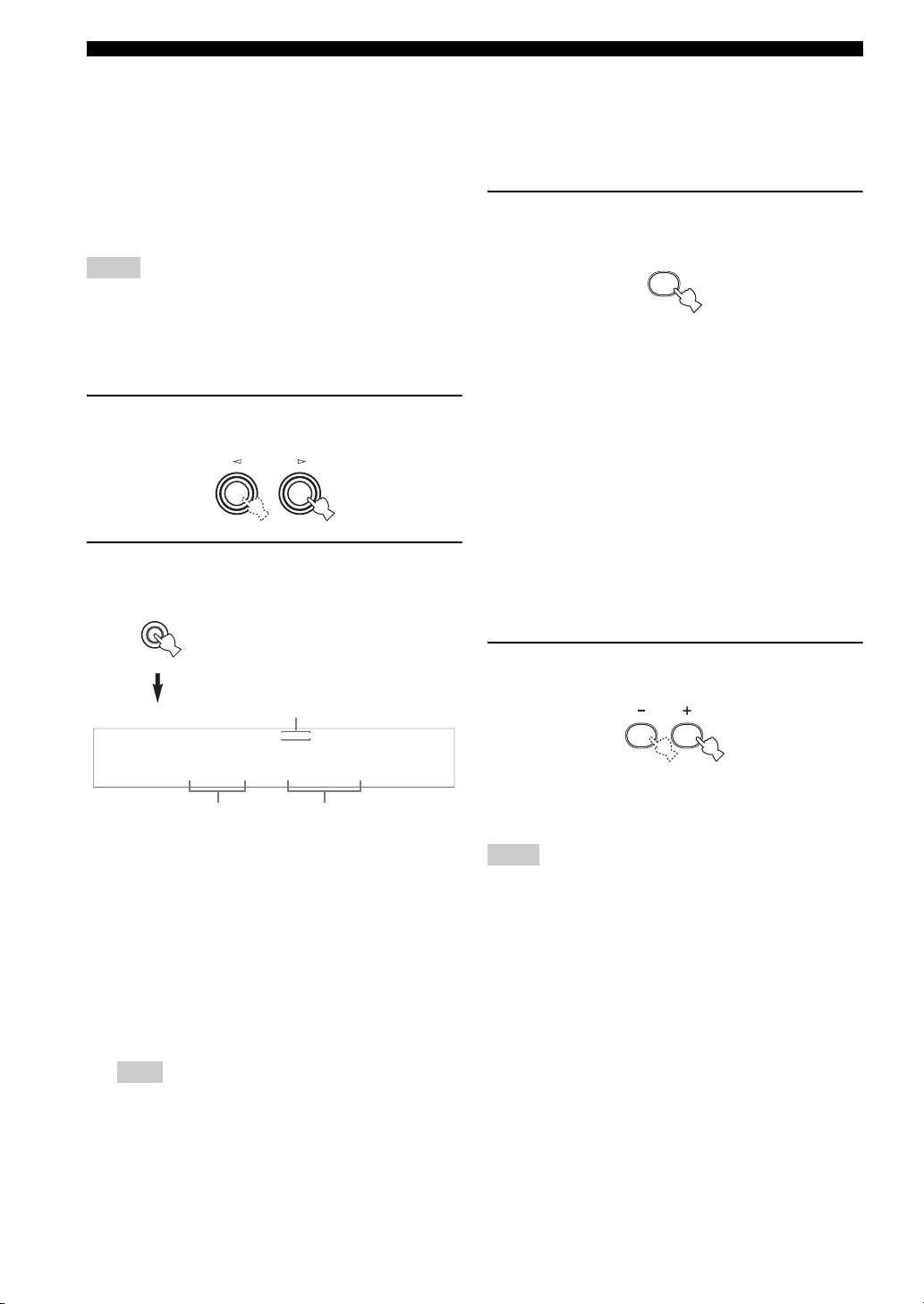
7 Press PROGRAM l / h on the front panel
(or press PROG +/– on the remote control)
repeatedly to select the desired sound field
program.
The name of the selected sound field program appears
in the front panel display.
See page 31 for details about sound field programs.
PROGRAM
Front panel
PROG PROG
or
Remote control
The Roxy Thtr
Currently selected
surround field program
Notes
• Choose a sound field program based on your listening
preference, not merely on the name of the program.
• When you select an input source, this unit automatically
selects the last sound field program used with the
corresponding input source.
• Sound field programs cannot be selected when the
component connected to the MULTI CH INPUT jacks is
selected as the input source (see page 25).
• When sampling frequencies higher than 48 kHz are input,
this unit is automatically set to the “STEREO” mode.
• To display information about the currently selected input
source in the front panel display, see page 28 for details.
24

Additional operations
■ Listening with headphones using
SILENT CINEMA
SILENT CINEMA allows you to enjoy multi-channel
music or movie sound, including Dolby Digital and DTS
sources, through ordinary headphones. SILENT CINEMA
activates automatically whenever you connect headphones
to the PHONES jack while listening to CINEMA DSP or
HiFi DSP sound field programs (see page 31). When
activated, the SILENT CINEMA indicator lights up in the
front panel display.
PLAYBACK
■ Selecting the MULTI CH INPUT
component as the input source
Use this feature to select the component connected to the
MULTI CH INPUT jacks (see page 16) as the input
source.
Press MULTI CH INPUT on the front panel (or
MULTI CH IN on the remote control) so that
“MULTI CH INPUT” appears in the front panel
display.
MULTI CH INPUT
or
MULTI CH IN
Notes
• SILENT CINEMA does not activate when the component
connected to the MULTI CH INPUT jacks is selected as the
input source.
• SILENT CINEMA is not effective when “2CH STEREO” (see
page 31) is selected or when this unit is in the “STRAIGHT”
mode (see page 33).
• The sound from the LFE channel will be mixed and output from
the headphones.
■ Muting the audio output
Press MUTE on the remote control to mute the
audio output.
Press MUTE again to resume the audio output.
MUTE
y
• You can also rotate VOLUME on the front panel or VOLUME
+/– on the remote control to resume the audio output.
• You can adjust the muting level by using “AUDIO MUTE” in
“OPTION MENU” (see page 48).
• The MUTE indicator flashes in the front panel display when the
audio output is muted and disappears from the front panel
display when the audio output is resumed.
Note
If you change the input source or the sound field program while
the audio output is being muted, this unit resumes the audio
output.
Front panel
Remote control
Note
When “MULTI CH INPUT” is shown in the front panel display,
no other source can be played. To select another input source with
INPUT l / h on the front panel (or one of the input selector
buttons on the remote control), press MULTI CH INPUT (or
MULTI CH IN on the remote control) so that “MULTI CH
INPUT” disappears from the front panel display.
■ Using the night listening mode
The night listening mode is designed to improve
listenability at lower volumes or at night.
Press NIGHT on the remote control to select
“NIGHT ON”.
NIGHT
y
When a night listening mode is selected, the NIGHT indicator
lights up in the front panel display.
Notes
• You can use the night listening mode with any of the sound field
programs.
• The night listening mode may vary in effectiveness depending
on the input source and the surround sound settings you use.
OPERATION
BASIC
25
English
PLAYBACK
■ Selecting the input modes
This unit comes with a variety of input jacks. Do the
following to select the type of input signals you want to
use.
y
• We recommend setting “INPUT MODE” to “AUTO” in most
cases.
• You can adjust the default input mode of this unit by using the
“INPUT MODE” parameter in “INPUT MENU” (see page 47).
Notes
• To play DTS-encoded CDs when using a digital audio
connection, be sure to set “INPUT MODE” to “DTS”.
• Depending on the player, DTS decoding may not be performed
correctly even if you make a digital connection between this
unit and the player.
1 Press INPUT l / h on the front panel to
select the desired input source.
INPUT
2 Press INPUT MODE on the front panel
repeatedly to select the desired input mode.
INPUT MODE
■ Adjusting speaker levels during
playback
You can adjust the output level of each speaker while
listening to a music source. This is also possible when
playing sources input at the MULTI CH INPUT jacks.
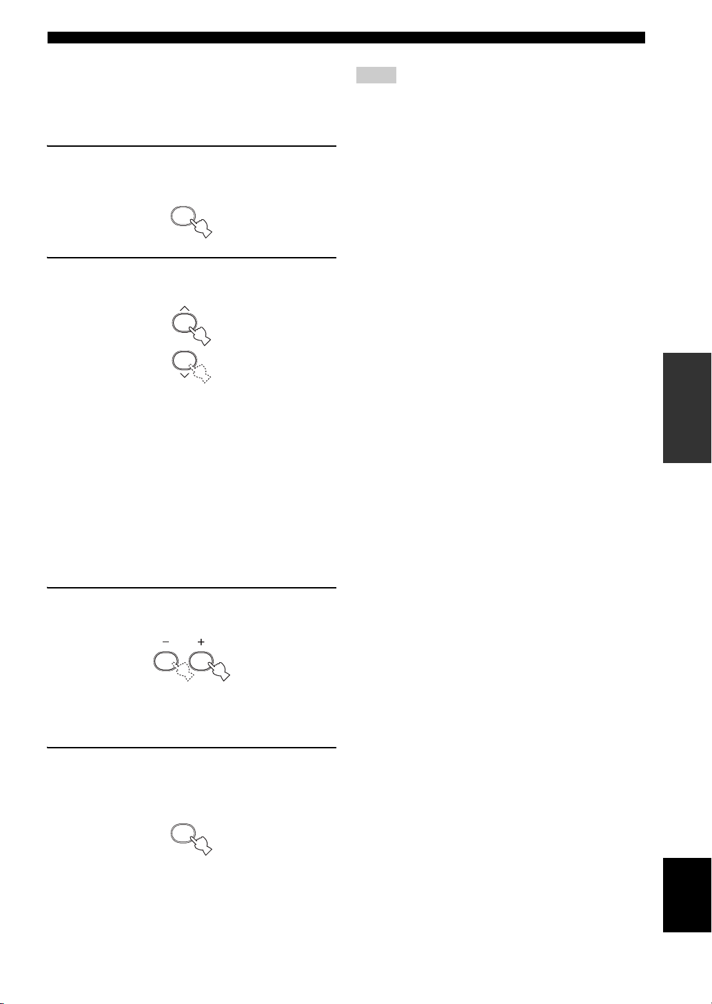
1 Press LEVEL repeatedly to select the
speaker you want to adjust.
LEVEL
• Select “FRONT L” to adjust the front left speaker
output level.
• Select “CENTER” to adjust the center speaker
output level.
• Select “FRONT R” to adjust the front right speaker
output level.
• Select “SUR. R” to adjust the surround right
speaker output level.
• Select “SUR. L” to adjust the surround left speaker
output level.
• Select “SWFR” to adjust the subwoofer output
level.
y
Once you press LEVEL on the remote control, you can also
select the speaker by pressing u / d.
Currently selected
input sources
VCR
V-AU X
DTV/CBL
DVD
MD/CD-R
TUNER CD
DVD AUTO
Currently selected
input source
AUTO Automatically selects input signals in
the following order:
1) Digital signals
2) Analog signals
DTS Selects only digital signals encoded in
DTS. If no DTS signals are input, no
sound is output.
ANALOG Selects only analog signals. If no
analog signals are input, no sound is
output.
Note
When “INPUT MODE” is set to “AUTO”, this unit
automatically switches to the appropriate decoder if a Dolby
Digital or DTS signal is detected.
Currently selected
input mode
2 Press +/– on the remote control to adjust the
speaker output level.
The control range is from +10 dB to –10 dB for the
center and surround speakers, and from 0 dB to
–20 dB for the front speakers and subwoofer.
Notes
• This operation will override the level adjustments made in
“SETUP” (see page 20).
• You cannot adjust speaker levels if “SPEAKER SET” in
“SOUND MENU” (see page 45) is set to “NONE”.
• You cannot adjust the subwoofer level if “BASS” in
“SPEAKER SET” (see page 45) in the set menu is set to
“FRNT”.
• If you use LEVEL to adjust speaker levels, the speaker levels
you previously set with the test tone will also change.
• If you select “SETUP” (see page 20) and then select “SET”,
speaker levels change in response to any changes you make in
“SETUP”.
26
PLAYBACK
■ Using the test tone
Use the test tone to set speaker levels so that the volume
from each speaker is identical when heard from your
listening position. This is also possible when playing
sources input at the MULTI CH INPUT jacks.
1 Press TEST.
The unit will output a test tone.
TEST
2 Press u / d repeatedly to select a speaker to
adjust.
• Select “TEST LEFT” to adjust the front left
speaker output level.
• Select “TEST CENTER” to adjust the center
speaker output level.
• Select “TEST RIGHT” to adjust the front right
speaker output level.
• Select “TEST SUR.R” to adjust the surround right
speaker output level.
• Select “TEST SUR.L” to adjust the surround left
speaker output level.
• Select “TEST SUBWOOFER” to adjust the
subwoofer output level.
Notes
• You cannot use the test tone if headphones are connected to the
PHONES jack. Remove the headphones from the PHONES
jack.
• This operation will override the level adjustments made in
“SETUP” (see page 20).
• You cannot adjust speaker levels if “SPEAKER SET” in
“SOUND MENU” (see page 45) is set to “NONE”.
• You cannot adjust the subwoofer level if “BASS” in
“SPEAKER SET” (see page 45) in the set menu is set to
“FRNT”.
• If you use TEST to adjust speaker levels, the speaker levels you
previously adjust during playback will also change.
• If you select “SETUP” (see page 20) and then select “SET”,
speaker levels change in response to any changes you make in
“SETUP”.
y
Depending on the source, the speaker levels set with the test tone
may not be to your liking. In this case, adjust the speaker levels
while listening to the source.
OPERATION
BASIC
3 Press +/– on the remote control to adjust the
speaker output level.
The control range is from +10 dB to –10 dB for the
center and surround speakers, and from 0 dB to
–20 dB for the front speakers and subwoofer.
4 Press TEST on the remote control when you
have completed your adjustment.
The test tone halts.
TEST
English
27

PLAYBACK
■ Displaying information about the input
source
You can display the format, sampling frequency, channel
and bit rate of the current input signal.
1 Press one of the input selector buttons on
the remote control to select the desired input
source.
2 Press STRAIGHT to select “STRAIGHT”.
STRAIGHT
3 Press u / d to display the following
information about the input source.
FORMAT
Signal format display. When this unit cannot detect a
digital signal, it automatically switches to analog
input.
Display status:
Analog, Digital, Dolby Digital, DTS, PCM,
Unknown Digital
Note
“Unknown Digital” appears when this unit detects any
undecodable digital signal.
CHANNEL
Number of source channels in the input signal (front/
surround/LFE). For example, a multi-channel
soundtrack with 3 front channels, 2 surround
channels and LFE, is displayed as “3/2/LFE”.
SAMPLING
Sampling frequency.
Display status: 32kHz, 44.1kHz, 48kHz, 64kHz,
88.2kHz, 96kHz
BITRATE
Bit rate.
y
When you are displaying information about the input source, this
unit is in the “STRAIGHT” mode (see page 33). To turn back the
sound field program on, press STRAIGHT again.
28
 Loading...