

Yamaha RX-V3071 Owner Manual

AV Receiver
Owner’s Manual
English for Oceania
Be sure to read “Safety Brochure” (supplied booklet) before using this unit.
En 1

CONTENTS
Accessories . . . . . . . . . . . . . . . . . . . . . . . . . . . . . . . . . . . . . . . . . . . . . . . . . . . . . 5
FEATURES
What you can do with this unit . . . . . . . . . . . . . . . . . . . . . . . . . . . . . . . . . . . 6
Part names and functions . . . . . . . . . . . . . . . . . . . . . . . . . . . . . . . . . . . . . . . 8
Front panel . . . . . . . . . . . . . . . . . . . . . . . . . . . . . . . . . . . . . . . . . . . . . . . . . . . . . . . . . . . . . . . . . . . . . . . . . . . . . . . . . . . . . . .8
Front display (indicators) . . . . . . . . . . . . . . . . . . . . . . . . . . . . . . . . . . . . . . . . . . . . . . . . . . . . . . . . . . . . . . . . . . . . . . . . .10
Rear panel . . . . . . . . . . . . . . . . . . . . . . . . . . . . . . . . . . . . . . . . . . . . . . . . . . . . . . . . . . . . . . . . . . . . . . . . . . . . . . . . . . . . . . .11
Remote control . . . . . . . . . . . . . . . . . . . . . . . . . . . . . . . . . . . . . . . . . . . . . . . . . . . . . . . . . . . . . . . . . . . . . . . . . . . . . . . . . .12
SETUP
General setup procedure . . . . . . . . . . . . . . . . . . . . . . . . . . . . . . . . . . . . . . . 14
1 Connecting speakers . . . . . . . . . . . . . . . . . . . . . . . . . . . . . . . . . . . . . . . . . 15
Basic speaker configuration . . . . . . . . . . . . . . . . . . . . . . . . . . . . . . . . . . . . . . . . . . . . . . . . . . . . . . . . . . . . . . . . . . . . . .16
Advanced speaker configuration . . . . . . . . . . . . . . . . . . . . . . . . . . . . . . . . . . . . . . . . . . . . . . . . . . . . . . . . . . . . . . . . .21
Input/output jacks and cables . . . . . . . . . . . . . . . . . . . . . . . . . . . . . . . . . . 30
2 Connecting a TV . . . . . . . . . . . . . . . . . . . . . . . . . . . . . . . . . . . . . . . . . . . . . . 31
3 Connecting playback devices . . . . . . . . . . . . . . . . . . . . . . . . . . . . . . . . . 37
Connecting video devices (BD/DVD players, etc.) . . . . . . . . . . . . . . . . . . . . . . . . . . . . . . . . . . . . . . . . . . . . . . . . . .37
Connecting audio devices (CD players, etc.) . . . . . . . . . . . . . . . . . . . . . . . . . . . . . . . . . . . . . . . . . . . . . . . . . . . . . . .39
Connecting to the jacks on the front panel . . . . . . . . . . . . . . . . . . . . . . . . . . . . . . . . . . . . . . . . . . . . . . . . . . . . . . . .40
4 Connecting the FM/AM antennas . . . . . . . . . . . . . . . . . . . . . . . . . . . . . . 41
5 Connecting to the network . . . . . . . . . . . . . . . . . . . . . . . . . . . . . . . . . . . 42
6 Connecting other devices . . . . . . . . . . . . . . . . . . . . . . . . . . . . . . . . . . . . . 43
Connecting video/audio recording devices . . . . . . . . . . . . . . . . . . . . . . . . . . . . . . . . . . . . . . . . . . . . . . . . . . . . . . .43
Connecting a device with analog multi-channel output . . . . . . . . . . . . . . . . . . . . . . . . . . . . . . . . . . . . . . . . . . .43
Connecting a device compatible with SCENE link playback (remote connection) . . . . . . . . . . . . . . . . . . .44
Connecting a device compatible with the trigger function . . . . . . . . . . . . . . . . . . . . . . . . . . . . . . . . . . . . . . . . .44
7 Connecting the power cable . . . . . . . . . . . . . . . . . . . . . . . . . . . . . . . . . . 45
8 Selecting an on-screen menu language . . . . . . . . . . . . . . . . . . . . . . . . 46
9 Optimizing the speaker settings automatically (YPAO) . . . . . . . . . 47
Measuring at one listening position (single measure) . . . . . . . . . . . . . . . . . . . . . . . . . . . . . . . . . . . . . . . . . . . . . 50
Measuring at multiple listening positions (multi measure) . . . . . . . . . . . . . . . . . . . . . . . . . . . . . . . . . . . . . . . . 51
Checking the measurement results . . . . . . . . . . . . . . . . . . . . . . . . . . . . . . . . . . . . . . . . . . . . . . . . . . . . . . . . . . . . . . 53
Reloading the previous YPAO results . . . . . . . . . . . . . . . . . . . . . . . . . . . . . . . . . . . . . . . . . . . . . . . . . . . . . . . . . . . . . 54
Error messages . . . . . . . . . . . . . . . . . . . . . . . . . . . . . . . . . . . . . . . . . . . . . . . . . . . . . . . . . . . . . . . . . . . . . . . . . . . . . . . . . . 55
Warning messages . . . . . . . . . . . . . . . . . . . . . . . . . . . . . . . . . . . . . . . . . . . . . . . . . . . . . . . . . . . . . . . . . . . . . . . . . . . . . . 56
PLAYBACK
Basic playback procedure . . . . . . . . . . . . . . . . . . . . . . . . . . . . . . . . . . . . . . 57
Selecting an HDMI output jack . . . . . . . . . . . . . . . . . . . . . . . . . . . . . . . . . . . . . . . . . . . . . . . . . . . . . . . . . . . . . . . . . . . 57
Selecting the input source and favorite settings at once (SCENE) . . 58
Configuring scene assignments . . . . . . . . . . . . . . . . . . . . . . . . . . . . . . . . . . . . . . . . . . . . . . . . . . . . . . . . . . . . . . . . . . 59
Selecting the sound mode . . . . . . . . . . . . . . . . . . . . . . . . . . . . . . . . . . . . . . 60
Enjoying sound field effects (CINEMA DSP) . . . . . . . . . . . . . . . . . . . . . . . . . . . . . . . . . . . . . . . . . . . . . . . . . . . . . . . 61
Enjoying unprocessed playback . . . . . . . . . . . . . . . . . . . . . . . . . . . . . . . . . . . . . . . . . . . . . . . . . . . . . . . . . . . . . . . . . 63
Enjoying pure high fidelity sound (Pure Direct) . . . . . . . . . . . . . . . . . . . . . . . . . . . . . . . . . . . . . . . . . . . . . . . . . . . 64
Enjoying compressed music with enhanced sound (Compressed Music Enhancer) . . . . . . . . . . . . . . . . . 64
Enjoying surround sound with headphones (SILENT CINEMA) . . . . . . . . . . . . . . . . . . . . . . . . . . . . . . . . . . . . . 64
Listening to FM/AM radio . . . . . . . . . . . . . . . . . . . . . . . . . . . . . . . . . . . . . . 65
Selecting a frequency for reception . . . . . . . . . . . . . . . . . . . . . . . . . . . . . . . . . . . . . . . . . . . . . . . . . . . . . . . . . . . . . . 65
Registering favorite radio stations (preset) . . . . . . . . . . . . . . . . . . . . . . . . . . . . . . . . . . . . . . . . . . . . . . . . . . . . . . . 65
Operating the radio on the TV . . . . . . . . . . . . . . . . . . . . . . . . . . . . . . . . . . . . . . . . . . . . . . . . . . . . . . . . . . . . . . . . . . . 66
Playing back iPod music/videos . . . . . . . . . . . . . . . . . . . . . . . . . . . . . . . . 68
Connecting an iPod . . . . . . . . . . . . . . . . . . . . . . . . . . . . . . . . . . . . . . . . . . . . . . . . . . . . . . . . . . . . . . . . . . . . . . . . . . . . . 68
Playback of iPod contents . . . . . . . . . . . . . . . . . . . . . . . . . . . . . . . . . . . . . . . . . . . . . . . . . . . . . . . . . . . . . . . . . . . . . . . 70
Playing back music via Bluetooth . . . . . . . . . . . . . . . . . . . . . . . . . . . . . . . 73
Connecting a Bluetooth receiver . . . . . . . . . . . . . . . . . . . . . . . . . . . . . . . . . . . . . . . . . . . . . . . . . . . . . . . . . . . . . . . . . 73
Pairing Bluetooth components . . . . . . . . . . . . . . . . . . . . . . . . . . . . . . . . . . . . . . . . . . . . . . . . . . . . . . . . . . . . . . . . . . 73
Establishing a wireless connection and playing back . . . . . . . . . . . . . . . . . . . . . . . . . . . . . . . . . . . . . . . . . . . . . 74
En 2

Playing back music stored on a USB storage device . . . . . . . . . . . . . . 75
Connecting a USB storage device . . . . . . . . . . . . . . . . . . . . . . . . . . . . . . . . . . . . . . . . . . . . . . . . . . . . . . . . . . . . . . . . .75
Playback of USB storage device contents . . . . . . . . . . . . . . . . . . . . . . . . . . . . . . . . . . . . . . . . . . . . . . . . . . . . . . . . .75
Playing back music stored on PCs . . . . . . . . . . . . . . . . . . . . . . . . . . . . . . . 78
Media sharing setup . . . . . . . . . . . . . . . . . . . . . . . . . . . . . . . . . . . . . . . . . . . . . . . . . . . . . . . . . . . . . . . . . . . . . . . . . . . . .78
Playback of PC music contents . . . . . . . . . . . . . . . . . . . . . . . . . . . . . . . . . . . . . . . . . . . . . . . . . . . . . . . . . . . . . . . . . . . 78
Listening to Internet radio . . . . . . . . . . . . . . . . . . . . . . . . . . . . . . . . . . . . . . 81
Playing back music in multiple rooms (multi-zone) . . . . . . . . . . . . . . . 83
Preparing for Zone2, Zone3 or Zone4 . . . . . . . . . . . . . . . . . . . . . . . . . . . . . . . . . . . . . . . . . . . . . . . . . . . . . . . . . . . . .83
Controlling Zone2, Zone3 or Zone4 . . . . . . . . . . . . . . . . . . . . . . . . . . . . . . . . . . . . . . . . . . . . . . . . . . . . . . . . . . . . . . .87
Useful functions . . . . . . . . . . . . . . . . . . . . . . . . . . . . . . . . . . . . . . . . . . . . . . . 89
Registering favorite items (shortcut) . . . . . . . . . . . . . . . . . . . . . . . . . . . . . . . . . . . . . . . . . . . . . . . . . . . . . . . . . . . . . .89
Controlling this unit from the web browser (web control) . . . . . . . . . . . . . . . . . . . . . . . . . . . . . . . . . . . . . . . . .90
Viewing the current status . . . . . . . . . . . . . . . . . . . . . . . . . . . . . . . . . . . . . . . . . . . . . . . . . . . . . . . . . . . . . . . . . . . . . . . .92
Configuring settings in accordance with a playback source (Option menu)
Option menu items . . . . . . . . . . . . . . . . . . . . . . . . . . . . . . . . . . . . . . . . . . . . . . . . . . . . . . . . . . . . . . . . . . . . . . . . . . . . . .93
. . . 93
CONFIGURATIONS
Configuring input sources (Input menu) . . . . . . . . . . . . . . . . . . . . . . . . . 96
Input menu items . . . . . . . . . . . . . . . . . . . . . . . . . . . . . . . . . . . . . . . . . . . . . . . . . . . . . . . . . . . . . . . . . . . . . . . . . . . . . . . .96
Configuring the SCENE function (Scene menu) . . . . . . . . . . . . . . . . . . . 98
Scene menu items . . . . . . . . . . . . . . . . . . . . . . . . . . . . . . . . . . . . . . . . . . . . . . . . . . . . . . . . . . . . . . . . . . . . . . . . . . . . . . . 99
Configuring sound programs/surround decoders (Sound Program menu)
Sound Program menu items . . . . . . . . . . . . . . . . . . . . . . . . . . . . . . . . . . . . . . . . . . . . . . . . . . . . . . . . . . . . . . . . . . . . 102
Configuring various functions (Setup menu) . . . . . . . . . . . . . . . . . . . . 104
Setup menu items . . . . . . . . . . . . . . . . . . . . . . . . . . . . . . . . . . . . . . . . . . . . . . . . . . . . . . . . . . . . . . . . . . . . . . . . . . . . . 105
Speaker (Manual Setup) . . . . . . . . . . . . . . . . . . . . . . . . . . . . . . . . . . . . . . . . . . . . . . . . . . . . . . . . . . . . . . . . . . . . . . . . 107
Sound . . . . . . . . . . . . . . . . . . . . . . . . . . . . . . . . . . . . . . . . . . . . . . . . . . . . . . . . . . . . . . . . . . . . . . . . . . . . . . . . . . . . . . . . . 111
Video . . . . . . . . . . . . . . . . . . . . . . . . . . . . . . . . . . . . . . . . . . . . . . . . . . . . . . . . . . . . . . . . . . . . . . . . . . . . . . . . . . . . . . . . . . 112
HDMI . . . . . . . . . . . . . . . . . . . . . . . . . . . . . . . . . . . . . . . . . . . . . . . . . . . . . . . . . . . . . . . . . . . . . . . . . . . . . . . . . . . . . . . . . . 115
Network . . . . . . . . . . . . . . . . . . . . . . . . . . . . . . . . . . . . . . . . . . . . . . . . . . . . . . . . . . . . . . . . . . . . . . . . . . . . . . . . . . . . . . . 116
Multi Zone . . . . . . . . . . . . . . . . . . . . . . . . . . . . . . . . . . . . . . . . . . . . . . . . . . . . . . . . . . . . . . . . . . . . . . . . . . . . . . . . . . . . . 117
Function . . . . . . . . . . . . . . . . . . . . . . . . . . . . . . . . . . . . . . . . . . . . . . . . . . . . . . . . . . . . . . . . . . . . . . . . . . . . . . . . . . . . . . . 119
Language . . . . . . . . . . . . . . . . . . . . . . . . . . . . . . . . . . . . . . . . . . . . . . . . . . . . . . . . . . . . . . . . . . . . . . . . . . . . . . . . . . . . . . 121
. . . 101
Viewing information about this unit (Information menu) . . . . . . . . 122
Types of information . . . . . . . . . . . . . . . . . . . . . . . . . . . . . . . . . . . . . . . . . . . . . . . . . . . . . . . . . . . . . . . . . . . . . . . . . . . 122
Configuring the system settings (ADVANCED SETUP menu) . . . . . 123
ADVANCED SETUP menu items . . . . . . . . . . . . . . . . . . . . . . . . . . . . . . . . . . . . . . . . . . . . . . . . . . . . . . . . . . . . . . . . . 124
Changing the speaker impedance setting (SPEAKER IMP.) . . . . . . . . . . . . . . . . . . . . . . . . . . . . . . . . . . . . . . . 124
Turning on/off the remote control sensor (REMOTE SENSOR) . . . . . . . . . . . . . . . . . . . . . . . . . . . . . . . . . . . . 124
Selecting the remote control ID (REMOTE CON AMP) . . . . . . . . . . . . . . . . . . . . . . . . . . . . . . . . . . . . . . . . . . . . 124
Switching the video signal type (TV FORMAT) . . . . . . . . . . . . . . . . . . . . . . . . . . . . . . . . . . . . . . . . . . . . . . . . . . . 125
Removing the limitation on HDMI video output (MONITOR CHECK) . . . . . . . . . . . . . . . . . . . . . . . . . . . . . . 125
Backing up/recovering the settings (RECOV./BACKUP) . . . . . . . . . . . . . . . . . . . . . . . . . . . . . . . . . . . . . . . . . . . 125
Restoring the default settings (INITIALIZE) . . . . . . . . . . . . . . . . . . . . . . . . . . . . . . . . . . . . . . . . . . . . . . . . . . . . . . . 126
Updating the firmware (FIRM UPDATE) . . . . . . . . . . . . . . . . . . . . . . . . . . . . . . . . . . . . . . . . . . . . . . . . . . . . . . . . . . 126
Checking the firmware version (VERSION) . . . . . . . . . . . . . . . . . . . . . . . . . . . . . . . . . . . . . . . . . . . . . . . . . . . . . . . 126
Controlling external devices with the remote control . . . . . . . . . . . 127
Setting remote control codes . . . . . . . . . . . . . . . . . . . . . . . . . . . . . . . . . . . . . . . . . . . . . . . . . . . . . . . . . . . . . . . . . . . 127
Programming from other remote controls (learning) . . . . . . . . . . . . . . . . . . . . . . . . . . . . . . . . . . . . . . . . . . . . 129
Editing device names . . . . . . . . . . . . . . . . . . . . . . . . . . . . . . . . . . . . . . . . . . . . . . . . . . . . . . . . . . . . . . . . . . . . . . . . . . . 130
Operating multiple functions at once (macro) . . . . . . . . . . . . . . . . . . . . . . . . . . . . . . . . . . . . . . . . . . . . . . . . . . . 131
Resetting the remote control configurations . . . . . . . . . . . . . . . . . . . . . . . . . . . . . . . . . . . . . . . . . . . . . . . . . . . . 132
Using the simplified remote control . . . . . . . . . . . . . . . . . . . . . . . . . . . . 134
Updating the firmware of this unit . . . . . . . . . . . . . . . . . . . . . . . . . . . . . 135
APPENDIX
Frequently asked questions . . . . . . . . . . . . . . . . . . . . . . . . . . . . . . . . . . . 136
Troubleshooting . . . . . . . . . . . . . . . . . . . . . . . . . . . . . . . . . . . . . . . . . . . . . . 137
Power and system . . . . . . . . . . . . . . . . . . . . . . . . . . . . . . . . . . . . . . . . . . . . . . . . . . . . . . . . . . . . . . . . . . . . . . . . . . . . . . 137
Audio . . . . . . . . . . . . . . . . . . . . . . . . . . . . . . . . . . . . . . . . . . . . . . . . . . . . . . . . . . . . . . . . . . . . . . . . . . . . . . . . . . . . . . . . . . 138
Video . . . . . . . . . . . . . . . . . . . . . . . . . . . . . . . . . . . . . . . . . . . . . . . . . . . . . . . . . . . . . . . . . . . . . . . . . . . . . . . . . . . . . . . . . . 139
FM/AM radio . . . . . . . . . . . . . . . . . . . . . . . . . . . . . . . . . . . . . . . . . . . . . . . . . . . . . . . . . . . . . . . . . . . . . . . . . . . . . . . . . . . 140
USB and network . . . . . . . . . . . . . . . . . . . . . . . . . . . . . . . . . . . . . . . . . . . . . . . . . . . . . . . . . . . . . . . . . . . . . . . . . . . . . . . 141
Remote control . . . . . . . . . . . . . . . . . . . . . . . . . . . . . . . . . . . . . . . . . . . . . . . . . . . . . . . . . . . . . . . . . . . . . . . . . . . . . . . . 142
Error indications on the front display . . . . . . . . . . . . . . . . . . . . . . . . . . 143
En 3

Glossary . . . . . . . . . . . . . . . . . . . . . . . . . . . . . . . . . . . . . . . . . . . . . . . . . . . . . . 144
Audio information . . . . . . . . . . . . . . . . . . . . . . . . . . . . . . . . . . . . . . . . . . . . . . . . . . . . . . . . . . . . . . . . . . . . . . . . . . . . . 144
Video information . . . . . . . . . . . . . . . . . . . . . . . . . . . . . . . . . . . . . . . . . . . . . . . . . . . . . . . . . . . . . . . . . . . . . . . . . . . . . . 146
Video signal flow . . . . . . . . . . . . . . . . . . . . . . . . . . . . . . . . . . . . . . . . . . . . . . . . . . . . . . . . . . . . . . . . . . . . . . . . . . . . . . . 147
Information on HDMI . . . . . . . . . . . . . . . . . . . . . . . . . . . . . . . . . . . . . . . . . 148
HDMI Control . . . . . . . . . . . . . . . . . . . . . . . . . . . . . . . . . . . . . . . . . . . . . . . . . . . . . . . . . . . . . . . . . . . . . . . . . . . . . . . . . . 148
HDMI signal compatibility . . . . . . . . . . . . . . . . . . . . . . . . . . . . . . . . . . . . . . . . . . . . . . . . . . . . . . . . . . . . . . . . . . . . . . 149
Reference diagram (rear panel) . . . . . . . . . . . . . . . . . . . . . . . . . . . . . . . . 150
Trademarks . . . . . . . . . . . . . . . . . . . . . . . . . . . . . . . . . . . . . . . . . . . . . . . . . . 151
Specifications . . . . . . . . . . . . . . . . . . . . . . . . . . . . . . . . . . . . . . . . . . . . . . . . 152
En 4
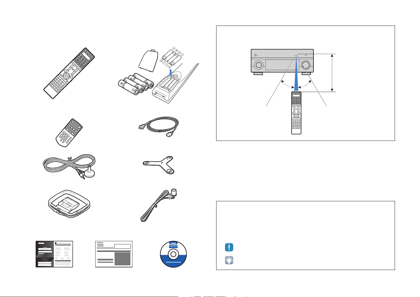
Accessories
Check that the following accessories are supplied with this product.
■ Remote control ■ Batteries (AAA, LR03, UM-4) (x 4)
Insert into the remote control in the correct polarity (+/-)
■ Simplified remote control ■ Power cable
* The figure of the supplied power cable differs depending
on regions.
■ YPAO microphone ■ Microphone base
* Used for angle measurement during YPAO.
■ AM antenna ■ FM antenna
Operating range of the remote control
• Aim the remote control directly at the remote control sensor on this unit during operation.
Within 6 m
30° 30°
* The figure of the supplied FM antenna differs depending
on regions.
■ Easy Setup Guide ■ Safety Brochure ■
CD-ROM (Owner’s Manual)
• Some features are not available in certain regions.
• Design and specifications are subject to change in part as a result of improvements, etc. In case of
differences between the manual and product, the product has priority.
• This manual mainly explains operations using the supplied remote control.
• This manual describes both the “iPod” and “iPhone” as the “iPod”. “iPod” means both “iPod” and
“iPhone” unless the explanation describes exceptions.
• “ ” indicates the cautions concerning operations or setup of the unit.
• “ ” indicates the explanations for better use.
En 5
FEATURES
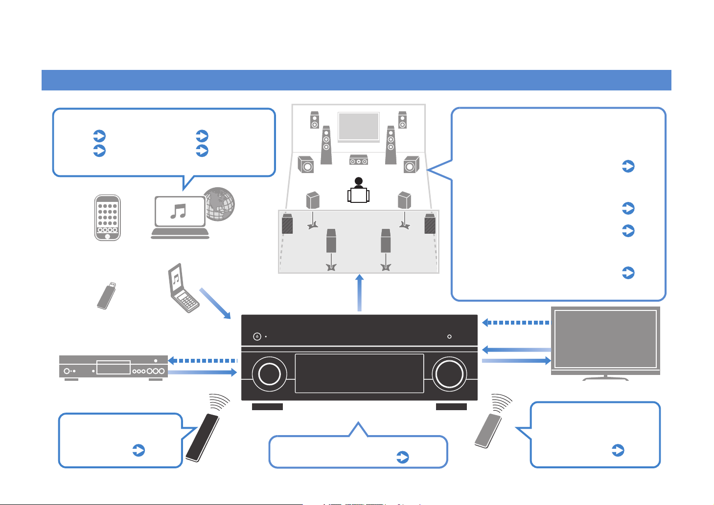
What you can do with this unit
Ready for any kind of contents
iPod
USB
*Requires optional Bluetooth receiver for playback via Bluetooth
p.68
p.75
iPod
USB device
BD/DVD player
Network
Bluetooth
Network contents
Audio
via Bluetooth
HDMI Control
Audio/Video
p.78 to p.81
p.73
Speakers
Audio
Supports 2 to 9 channel (plus rear presence)
speaker system and up to 2 subwoofer
connections. Allows you to enjoy favorite
acoustic spaces in various styles.
Plus, bi-amp connections, channel
expansion (with external power-amp)
p.21
and multi-zone configurations to
enhance your system
Automatically optimizing the speaker
settings to suit your room (YPAO)
Sound field reproductions like actual
movie theaters and concert halls from
p.47
p.61
stereo or multi-channel audio sources
(CINEMA DSP)
Enjoying compressed music with
enhanced sound (Compressed Music
p.64
Enhancer)
HDMI Control
Audio
Video
TV
Operating external
devices with the supplied
remote control
p.127
Remote control
of this unit
AV receiver (this unit)
Selecting the input source and favorite
settings at once (SCENE)
p.58
TV remote control
Operating the TV, AV
receiver and BD/DVD
player in combination
(HDMI Control)
p.148
En 6
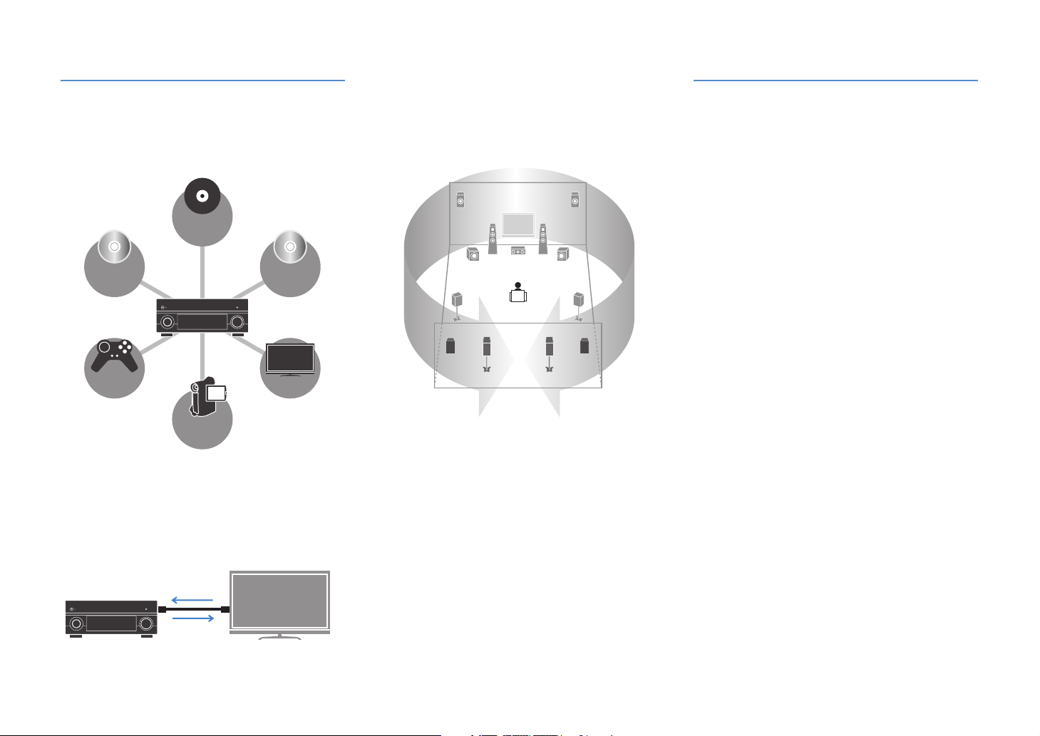
Full of useful functions!
● Connecting various devices (p.37)
A number of HDMI jacks and various input/output jacks
on this unit allow you to connect video devices such as
BD/DVD players, audio devices such as CD players,
game consoles and camcorders, and so on.
Turntable
BD/DVD
player
Game
console
Camcorder
● Playing back TV audio in surround sound
with a single HDMI cable connection
(Audio Return Channel: ARC) (p.31)
When using a TV that supports ARC, you only need a
single HDMI cable to connect the TV and this unit to
output video to the TV, input audio from the TV, and
transmit HDMI Control signals.
HDMI Control
TV audio
Video from
external device
CD player
TV
● Creating stereoscopic sound fields (p.63)
Connection of presence speakers enables to create an
unprecedented natural stereoscopic sound field in your
room (CINEMA DSP HD³). Even when no presence
speakers are connected, this unit automatically creates
Virtual Presence Speaker (VPS) to produce 3D surround
sound.
● Listening to FM/AM radio (p.65)
This unit is equipped with the built-in FM/AM tuner. You
can register favorite radio stations as presets.
● Enjoying pure high fidelity sound (p.64)
When the Pure Direct mode is enabled, this unit plays
back the selected source with the least circuitry. It
allows you to enjoy Hi-Fi sound quality.
● Easy operation with a TV screen
You can navigate the various contents (iPod, USB,
network, etc.), view the information, or configure the
settings using the on-screen menu.
At time like this
I want to connect a playback device using HDMI for video
and non-HDMI for audio...
Use “Audio Select” in the “Option” menu to specify the type
of an audio input jack to be used for the corresponding
input source (p.95).
Video and audio are not synchronized...
Use “Lipsync” in the “Setup” menu to adjust the delay
between video and audio output (p.111).
I want to hear audio from the TV speakers...
Use “Audio Output” in the “Setup” menu to select whether
to output audio signals through this unit and the TV (p.116).
I want to this unit to be turned off automatically when not in
use...
Use “Auto Power Down” in the “Setup” menu to set the
amount of time for auto-standby (p.119).
I want to change the on-screen menu language...
Use “Language” in the “Setup” menu to select a language
from English, Japanese, French, German, Spanish and
Russian (p.121).
I want to update the firmware...
Use “UPDATE” in the “ADVANCED SETUP” menu to update
the firmware of this unit (p.126). If this unit is connected to
the Internet, the corresponding message will be displayed
on the TV when a newer firmware is available (p.135).
There are many other settings to customize this unit.
For details, see the following pages.
●Input settings (p.96)
●Scene settings (p.99)
●Sound program and surround decoder settings (p.102)
●Various function settings (p.105)
●Information view (audio signal, video signal, etc.) (p.122)
●System settings (p.124)
En 7
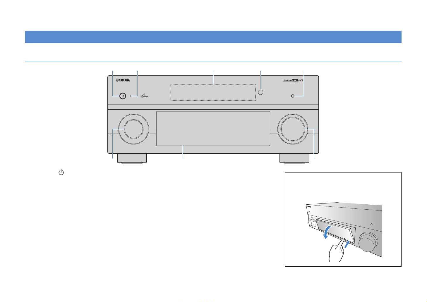
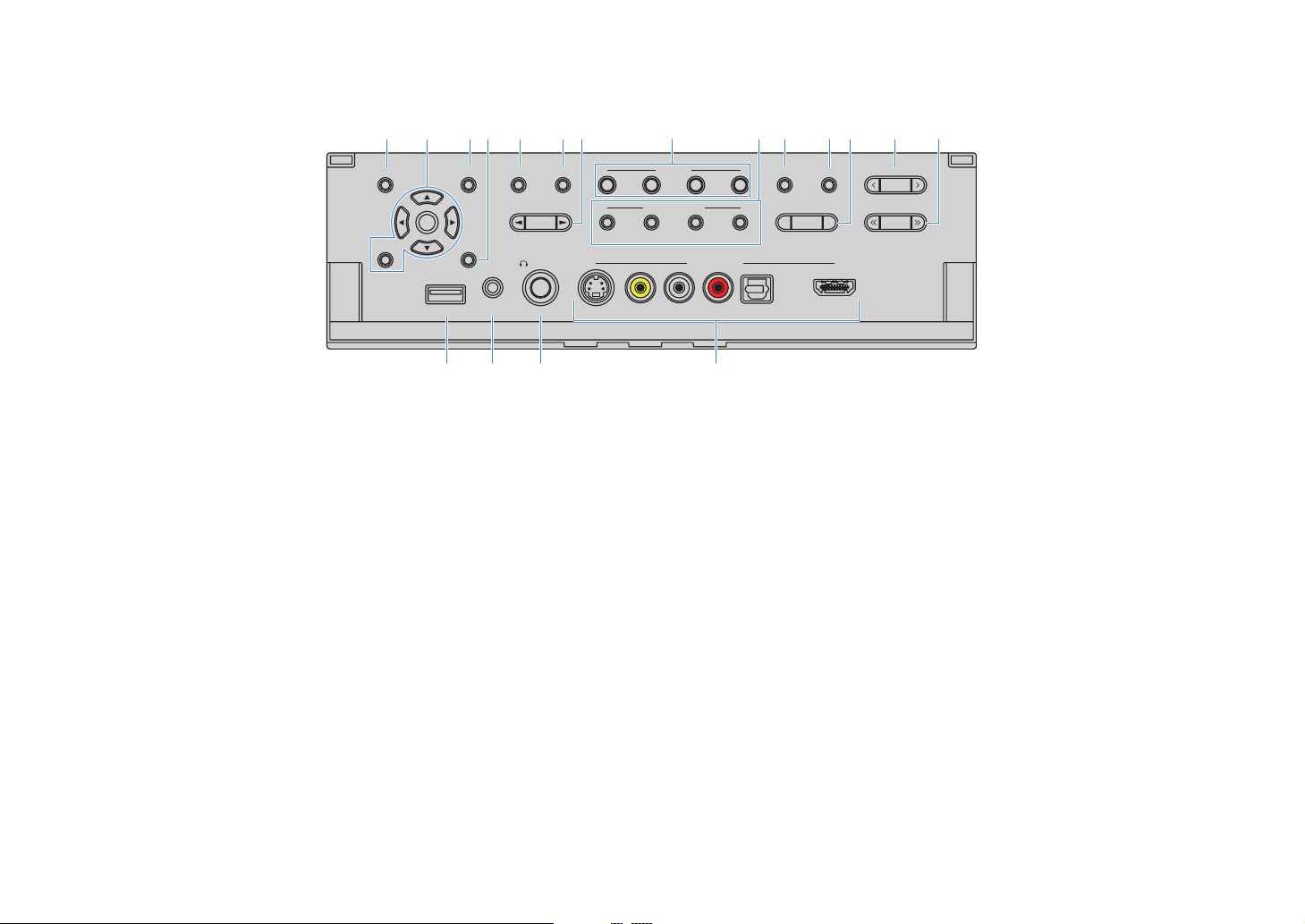
Part names and functions
Front panel
MAIN ZONE
6 7 8
1 MAIN ZONE
Turns on/off (standby) this unit.
2 Standby indicator
Lights up when this unit is in standby mode under any of the
following conditions.
- HDMI Control is enabled (p.148)
- The standby through function is enabled (p.116)
- The network standby function is enabled (p.117)
- The iPod is being charged (p.97)
- An iPod wireless system is connected (p.69)
3 Front display
Displays information (p.10).
4 Remote control sensor
Receives remote control signals (p.5).
5 PURE DIRECT
Enables/disables Pure Direct (p.64).
6 INPUT
Selects an input source.
NATURAL SOUND AV RECEIVER RX-V3071
7 Front panel door
8 VOLUME
TONE/BALANCEOPTIONON SCREEN
STRAIGHT
ENTER
PROGRAM FM AM TUNING/CH
DISPLAYRETURN
PHONES
USB
YPAO MIC
SILENT CINEMA
iPod/iPhone
1
ZONE 2
SCENE
2 3 4
MULTI ZONE
ZONE 3 ZONE 4
VIDEO AUX
ZONE CONTROL
ROPTICALL AUDIOVIDEOS VIDEO
For protecting controls and jacks (p.9).
Adjusts the volume.
INFO MEMORY
4
PRESET
HDMI IN
5321
PURE DIRECT
VOLUMEINPUT
Opening the front panel door
• To use controls or jacks behind the front panel door, gently
press the bottom of the door to open it. Keep the door closed
when not using controls or jacks behind the front panel door.
En 8
■ Inside of the front panel cover
SCENE
MULTI ZONE
HDMI IN
VIDEO AUX
TONE/BALANCEOPTIONON SCREEN
DISPLAYRETURN
STRAIGHT
1
ENTER
ZONE 2
2 3 4
ZONE CONTROL
INFO MEMORY
YPAO MIC
PHONES
SILENT CINEMA
USB
iPod/iPhone
PROGRAM FM AM TUNING/CH
PRESET
R OPTICALL AUDIOVIDEOS VIDEO
ZONE 3 ZONE 4
9 ON SCREEN
Displays the on-screen menu on the TV.
0 Menu operation keys
Cursor keys Select a menu or parameter.
ENTER Confirms a selected item.
RETURN Returns to the previous screen.
A OPTION
Displays the option menu (p.93).
B DISPLAY
Display the status information on the TV (p.92).
C TONE/BALANCE
Adjusts the high-frequency range and low-frequency range
of sounds output from speakers and headphones (p.94).
Adjusts the right/left channel volume balance for Zone2 or
Zone3 (p.88).
D STRAIGHT
Enables/disables the straight decode mode (p.63).
9 0 A CB D E F H I KJ L
G
M N O P
E PROGRAM
Selects a sound program or a surround decoder (p.60).
F SCENE
Selects the registered input source, sound program, HDMI
output and various settings at once. Additionally, you can
turn on this unit when it is in standby mode (p.58).
G MULTI ZONE
ZONE 2~4 Enables/disables the audio output to
ZONE CONTROL Switches the zones (main, Zone2, Zone3
each zone (p.87).
or Zone4) to operate with the front panel
controllers (p.87).
H INFO
Selects the information displayed on the front display (p.92).
I MEMORY
Registers FM/AM radio stations as preset stations (p.65).
Registers USB/network contents as shortcuts (p.89).
J FM/AM
Switches between FM and AM (p.65).
K PRESET
Selects a preset FM/AM radio station (p.66).
Selects a USB/network content from shortcuts (p.89).
L TUNING/CH
Selects the radio frequency (p.65).
M USB jack
For connecting a USB storage device (p.75) or an iPod via
USB (p.68).
N YPAO MIC jack
For connecting the supplied YPAO microphone (p.47).
O PHONES jack
For connecting headphones.
P VIDEO AUX jacks
For connecting camcorders, game consoles, etc (p.40).
En 9
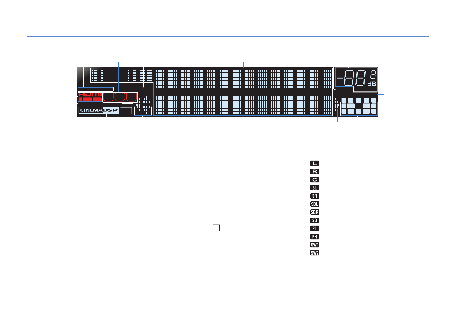
Front display (indicators)
2
1 43
STEREO
TUNED PARTY
ZONE
ZONE3ZONE
OUT 1INOUT 2
ENHANCER
9 BCB
2
SLEEP
0
HD
4
3
A
1 HDMI
Lights up during normal HDMI communication.
IN
Lights up when HDMI signals are being input.
OUT1/OUT2
Indicate the HDMI OUT jacks currently outputting an HDMI
signal.
2 STEREO
Lights up when this unit is receiving a stereo FM radio signal.
TUNED
Lights up when this unit is receiving an FM/AM radio station
signal.
3 ZONE indicators
Light up when the audio output to Zone2, Zone3 or Zone4 is
enabled.
4 PA RT Y
Lights up when this unit is in the party mode.
5 Information display
Displays the current status (input name, sound mode name,
etc). You can switch the information by pressing INFO (p.92).
5
6 MUTE
Flashes when audio is muted.
7 Volume indicator
Indicates the current volume.
8 ADAPTIVE DRC
Lights up when Adaptive DRC (p.94) is working.
9 ENHANCER
Lights up when Compressed Music Enhancer (p.64) is
working.
0 CINEMA DSP HD
Lights up when CINEMA DSP (p.61) is working.
CINEMA DSP HD
Lights up when CINEMA DSP HD³ (p.63) is working.
A SLEEP
Lights up when the sleep timer is on.
B Cursor indicators
Indicate the remote control cursor keys currently operational.
3
876
VOLUME
MUTE
PL
C Speaker indicators
Indicate speaker terminals from which signals are output.
Front speaker (L)
Front speaker (R)
Center speaker
Surround speaker (L)
Surround speaker (R)
Surround back speaker (L)
Surround back speaker (R)
Surround back speaker
Front/rear presence speakers (L)
Front/rear presence speakers (R)
Subwoofer (1)
Subwoofer (2)
DRCADAPTIVE
CL R
SW1SLSW2
SBLPL SBRSB PR
PR
SR
En 10
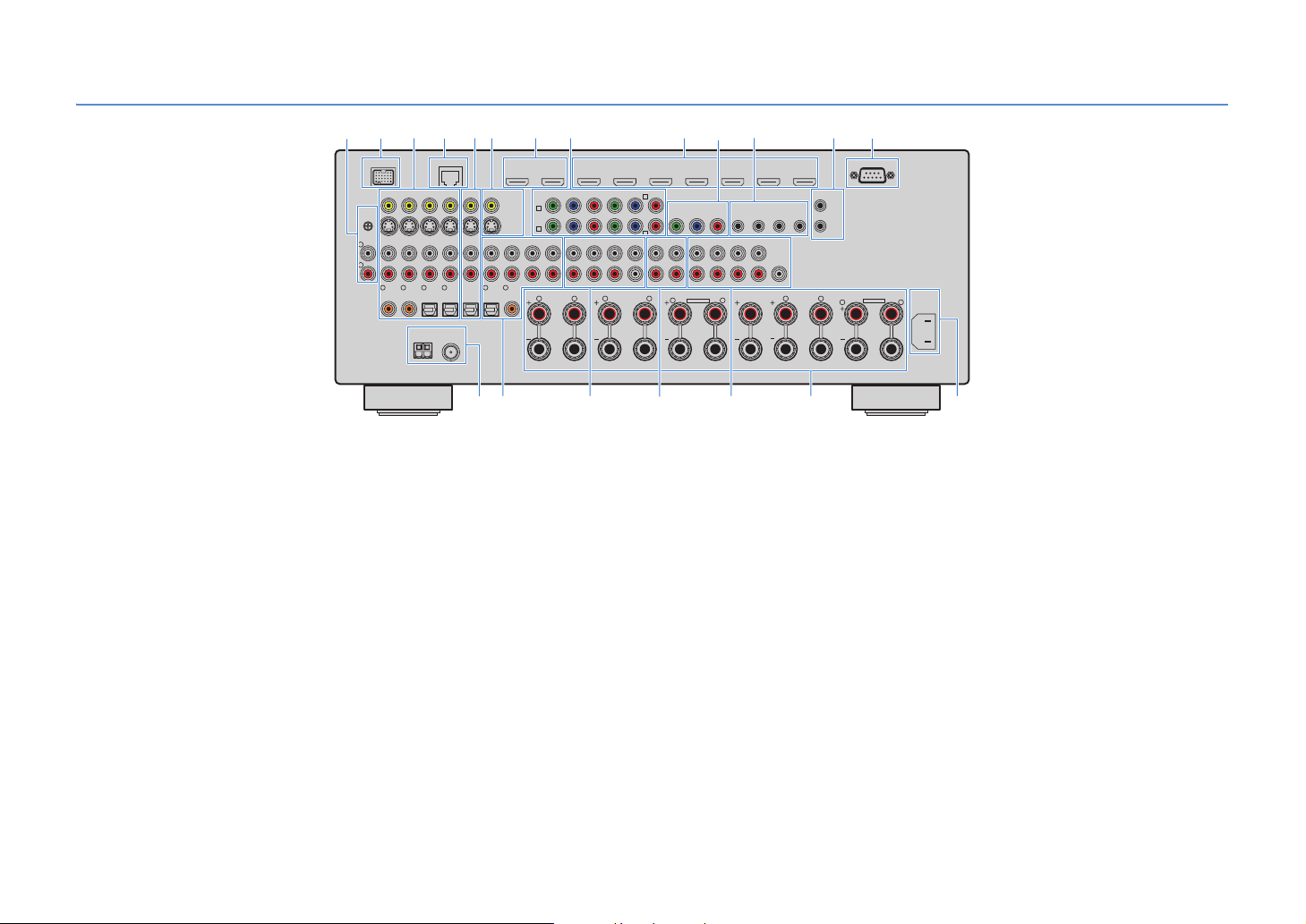
Rear panel
2
DOCK
(1 BD/DVD)
PHONO
GND
L
R
1
1 PHONO jacks
For connecting a turntable (p.39).
2 DOCK jack
For connecting an optional Yamaha products such as iPod
dock (p.69), iPod wireless system (p.69), and Bluetooth
receiver (p.73).
3 AV1~4 jacks
For connecting video/audio playback devices to input video/
audio signals (p.37).
4 NETWORK jack
For connecting to the network (p.42).
5 AV OUT jacks
For outputting video/audio to a recording device (VCR, tape
deck, etc.) (p.43).
For connecting an external amplifier used in Zone4 to output
audio signals (p.84).
6 MONITOR OUT/ZONE OUT
(composite video/S-video) jacks
For connecting a TV compatible with composite video or
S-video to output video signals (p.35).
For connecting a zone video monitor (p.85).
7 HDMI OUT 1~2 jacks
For connecting HDMI-compatible TVs to output video/audio
signals (p.31). When using ARC, TV audio signal is input
through the HDMI OUT 1 jack.
4
NETWORK
AV 3 AV 4AV 2
AV 1
2
COAXIAL
COAXIAL
ANTENNA
(4 RADIO)
AV OUT
AV OUT/
4
3
OPTICAL
OPTICAL
ZONE 4
SPEAKER IMPEDANCE
AM
FM
75Ω
AUDIO 1
(2 TV)
5
OPTICAL
1
MONITOR OUT/
ZONE OUT
(3 CD)
6
COAXIAL
ARC
7
HDMI OUT
AV 1
AV 2
AUDIO 3AUDIO 2
2
YP
A
B
AUDIO 4
SURROUND
R L
CENTER
SUBWOOFER
C
D
ZONE OUT/PRE OUT
ZONE 2/
F.PRESENCE
L
SINGLE
HDMI
MONITOR OUT/ZONE OUT
YPB PR
ZONE 3/
FRONT
R.PRESENCE
SPEAKERS
ZONE 2/ZONE 3/R.PRESENCE
R
EXTRA SP2
AV 2 AV 3 AV 4 AV 5 AV 6 AV 7
AV 1
(1 BD/DVD)
COMPONENT VIDEO
B PR
YPB PR
AV 3
AV 4
MULTI CH INPUT
FRONT
SURROUND SUR. BACK
SURROUND BACK
R
(SINGLE) (FRONT)
PRE OUT
SURROUND SUR. BACK
L
REMOTE
1
IN OUT2IN OUT
1
2
(REAR)
CENTER
SUBWOOFER
CENTER FRONT
R
TRIGGER
OUT
+12V 0.1A MAX.
L
1
2
R
C1 53 6 8 9 0 A B
RS-232C
ZONE 2/ZONE 3/F.PRESENCE/
BI–AMP
EXTRA SP1
AC IN
L
D E F G H I J
8 COMPONENT VIDEO (AV1~4) jacks
For connecting video playback devices compatible with
component video to input video signals (p.38).
9 HDMI (AV1~7) jacks
For connecting HDMI-compatible playback devices to input
video/audio signals (p.37).
0 MONITOR OUT/ZONE OUT
(component video) jacks
For connecting a TV compatible with component video to
output video signals (p.35).
For connecting a zone video monitor (p.85).
A REMOTE 1~2 (IN/OUT) jacks
For connecting a Yamaha product compatible with SCENE
link playback (p.44), or connecting an infrared signal
receiver/emitter to operate devices including this unit from
another room (p.86).
B TRIGGER OUT 1~2 jacks
For connecting devices that support the trigger function
(p.44).
C RS-232C terminal
This is a control expansion terminal for custom installation.
Consult your dealer for details.
D ANTENNA jacks
For connecting FM and AM antennas (p.41).
E AUDIO1~4 jacks
For connecting audio playback devices to input audio
signals (p.39).
F MULTI CH INPUT jacks
For connecting a device that supports multi-channel output
to input audio signals (p.43).
G ZONE OUT/PRE OUT jacks
For connecting an external amplifier used in Zone2 or Zone3
to output audio signals (p.84).
For connecting an external power amplifier for front and rear
presence channels (p.29).
H PRE OUT jacks
For connecting subwoofers with built-in amplifier (p.20) or an
external power amplifier (p.29).
I SPEAKERS terminals
For connecting speakers (p.15).
J AC IN
For connecting the supplied power cable (p.45).
En 11
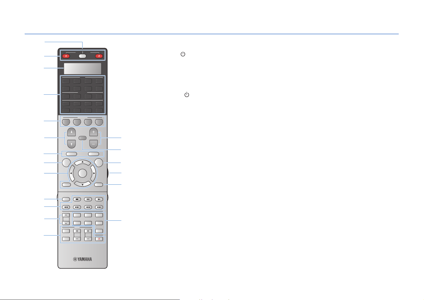
Remote control
1
SOURCE
2
RECEIVER
3
AV
1 2 3 4
MUTE
ENTER
USB NET
VOLUME
POP-UP/MENU
OPTION
V-AUX
D
E
F
G
5 6 7
4
5
6 C
7
8
AUDIO
1 2 3 4
MULTI
PHONO
TUNER
DOCK [ B ][ A ]
SCENE
1 2 3 4
PROGRAM
TOP MENU
ON SCREEN
9
RETURN DISPLAY
0
MODE
7
LIVE
A
B
PRESET
INPUT
MUTE
CLASSICAL
MOVIE
TV
TV VOL
ENTERTAIN
CLUB
STEREO STRAIGHT
PURE
DIRECT
TV CH
H
1 Remote control signal transmitter
Transmits infrared signals.
2 SOURCE
Turns on/off an external device.
SOURCE/RECEIVER
Switches the devices (this unit or external device) to operate
with the remote control (p.129). You can operate this unit
when this key lights up in orange, and an external device
when this key lights up in green.
RECEIVER
Turns on/off (standby) this unit.
3 Display window
Displays remote control information.
4 Input selection keys
Select an input source to play back.
AV1 ~7 AV1~7 jacks
V-A UX VIDEO AUX jacks (on the front panel)
AUDIO1~4 AUDIO1~4 jacks
PHONO PHONO jacks
MULTI MULTI CH INPUT jacks
USB USB jack (on the front panel)
NET NETWORK jack (press repeatedly to select a
DOCK DOCK jack
TUNER FM/AM radio
[A], [B] Changes the external device to operate with the
desired network source)
remote control without switching the input
source.
5 SCENE
Selects the assigned input source, sound program, HDMI
output and various settings at once. Additionally, you can
turn on this unit when it is in standby mode (p.58).
6 PROGRAM
Selects a sound program (p.60).
7 External device operation keys
Operate playback and menu display etc. for external
devices (p.129).
8 ON SCREEN
Displays the on-screen menu on the TV.
9 Menu operation keys
Cursor keys Select a menu or a parameter.
ENTER Confirms a selected item.
RETURN Returns to the previous screen.
0 MODE
Switches between stereo and monaural for FM radio reception.
Switches the iPod operation modes (p.71).
A PRESET
Selects a preset FM/AM radio station (p.66).
Selects a USB/network content from shortcuts (p.89).
B TV operation keys
Operate TV input, TV volume, etc (p.128).
C VOLUM E
Adjusts the volume.
D MUTE
Mutes the audio output.
E OPTION
Displays the option menu (p.93).
F LIGHT
Turns on the backlight of the remote control keys for about
10 seconds.
G DISPLAY
Displays the status information on the TV (p.92).
H Sound mode keys
Select a sound mode (p.60).
En 12

■ Inside of the remote control cover
SOURCE
RECEIVER
AV
1 2 3 4
USB NET
MUTE
VOLUME
POP-UP/MENU
ENTER
PART Y
FM
LIVE
CLUB
STEREO STRAIGHT
9
TV CH
V-AUX
OPTION
HDMI OUT
ENTERTAIN
TUN./ CH
PURE
SLEEP
DIRECT
LEVELENT
SETUPZONE
M
N
O
P
Q
R
I
J
K
L
5 6 7
AUDIO
1 2 3 4
MULTI
PHONO
TUNER
DOCK [ B ][ A ]
SCENE
1 2 3 4
PROGRAM
TOP MENU
ON SCREEN
RETURN DISPLAY
SUR.
ENHANCER
MODE
DECODE
MEMORY
INFO AM
2 3
1
CLASSICAL
PRESET
5
4 6
MOVIE
TV
87
INPUT
TV VOL
MUTE
0
10
I Sound mode keys
Select a sound mode (p.60).
J INFO
Selects the information displayed on the front display (p.92).
K Numeric keys
Enter numerical values such as radio frequencies.
L ZONE
Switches the zones (main, Zone2, Zone3 or Zone4) to
operate with the remote control (p.87).
M PA RT Y
Turns on/off the party mode (p.88).
N HDMI OUT
Selects HDMI OUT jacks to be used for video/audio output
(p.57).
O Radio keys
Operate the FM/AM radio when “TUNER” is selected as the
input source.
MEMORY Registers FM/AM radio stations as presets.
FM Switches to FM radio.
AM Switches to AM radio.
TUN./CH Selects the radio frequency.
P SLEEP
Switches this unit to standby mode automatically after a
specified period of time has elapsed (sleep timer). Press
repeatedly to set the time (120 min, 90 min, 60 min, 30 min,
off).
Q LEVEL
Adjusts the volume of each speaker (p.109).
R SETUP
Switches the remote control to the setup mode (p.127)
• To operate external devices with the remote control, register a
remote control code for each device in advance (p.127).
En 13

SETUP
General setup procedure
1 Connecting speakers (p.15)
2 Connecting a TV (p.31)
3 Connecting playback devices (p.37)
4 Connecting the FM/AM antennas (p.41)
5 Connecting to the network (p.42)
6 Connecting other devices (p.43)
7 Connecting the power cable (p.45)
8
Selecting an on-screen menu language (p.46)
Basic speaker configuration (p.16)
Select the speaker layout and connect the speakers to this unit.
Advanced speaker configuration (p.21)
Apply bi-amp connections, channel expansion (using an external power amplifier) or multi-zone configurations
to enhance the system.
Connect a TV to this unit.
Connect video devices (BD/DVD players, etc.) and audio devices (CD players, etc.) to this unit.
Connect the supplied FM/AM antennas to this unit.
Connect this unit to the network.
Connect external devices such as recording devices.
After all the connections are complete, plug in the power cable.
Select a desired on-screen menu language (default: English).
9
Optimizing the speaker settings automatically (YPAO) (p.47)
Now all the preparations are complete. Enjoy playing movies, music, radio, etc. with this unit!
Optimize the speaker settings such as volume balance and acoustic parameters to suit your room (YPAO).
En 14
Speaker connections
1
2 3 4 5 6 7 8 9
1 Connecting speakers
This unit has 9 built-in amplifiers. You can connect 2 to 11 speakers and up to 2 subwoofers (with built-in amplifier) to create the favorite acoustic space in your room.
You can also apply bi-amp connections, channel expansion (using an external power amplifier) or multi-zone configurations to enhance your system (p.21).
Caution
• This unit is configured for 8-ohm speakers at the factory. When connecting 6-ohm speakers, set the speaker impedance of this unit to “6 Ω MIN”. In this case, you can also use 4-ohm speakers as the front speakers. For
details, see “Setting the speaker impedance” (p.18).
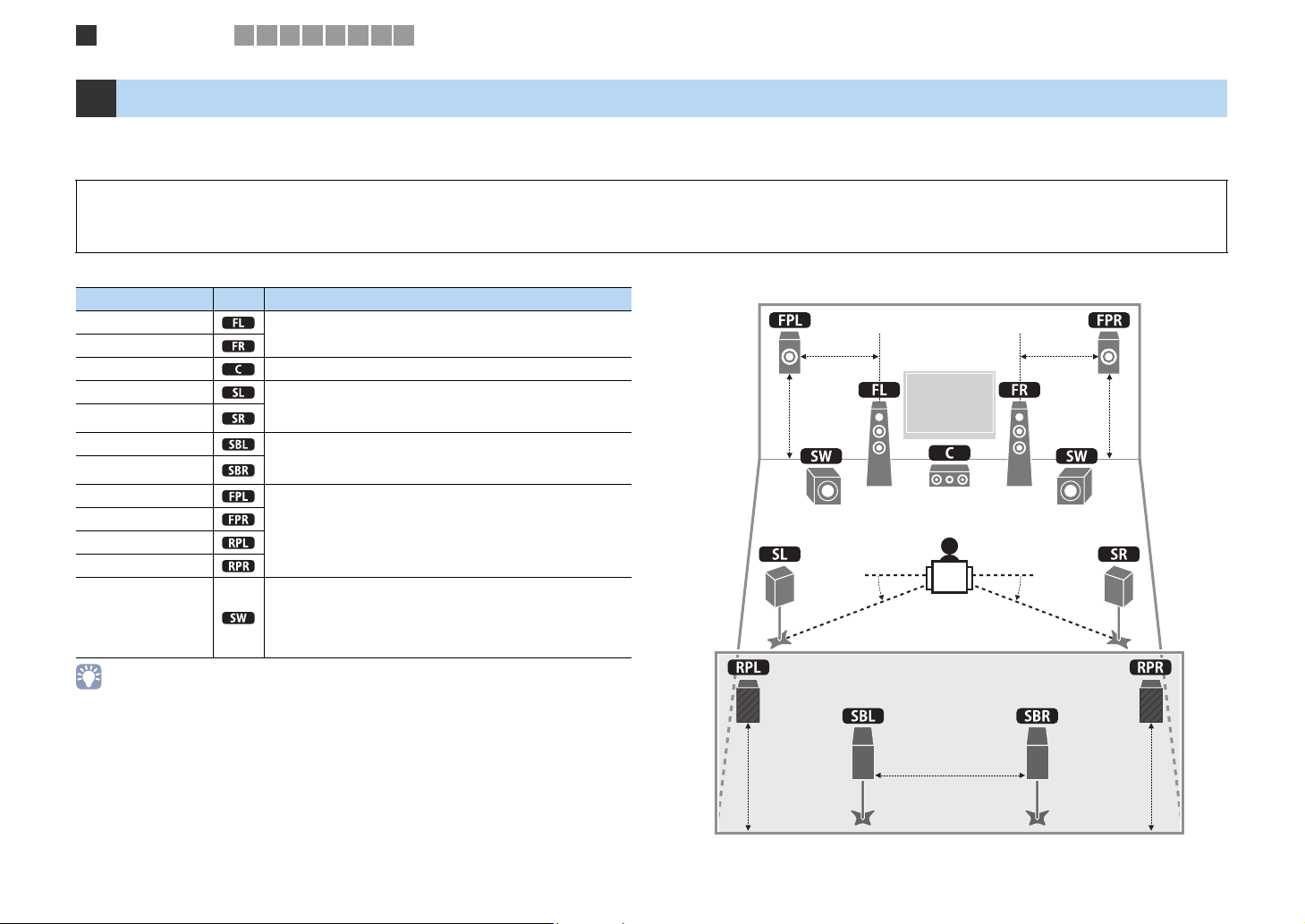
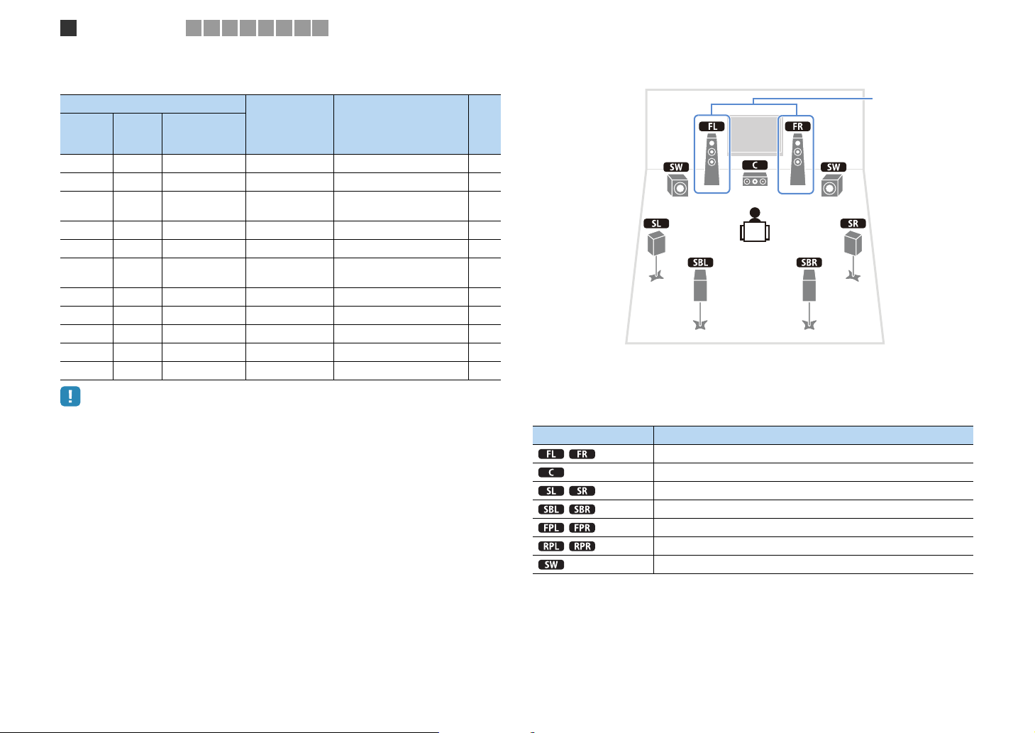
Functions of each speaker
Speaker type Abbr. Function
Front (L)
Front (R)
Center Produces center channel sounds (dialogs, vocals, etc).
Surround (L) Produce surround right/left channel sounds. Surround speakers
Surround (R)
Surround back (L) Produce surround back right/left channel sounds. When no
Surround back (R)
Front presence (L)
Front presence (R)
Rear presence (L)
Rear presence (R)
Subwoofer
• We recommend using presence speakers to have a full effect of the stereoscopic sound fields. However,
this unit creates Virtual Presence Speaker (VPS) using the front, center and surround speakers to produce
stereoscopic sound fields even when no presence speakers are connected (p.63).
• Use “Ideal speaker layout” (diagram on the right) as reference. You do not need to exactly adjust the
speaker layout to this diagram since the YPAO function of this unit will automatically optimize the speaker
settings (distance, etc.) to suit the speaker layout.
• When using only one surround back speaker, place it straight behind the listening position (middle of “SBL”
and “SBR” in the diagram).
Produce front right/left channel sounds (stereo sounds).
also produce surround back channel sounds when no surround
back speakers are connected.
surround back speakers are connected, Surround back channel
sounds are produced from the surround speakers.
Produce CINEMA DSP effect sounds. In combination with
CINEMA DSP HD³ (p.63), the presence speakers create a
natural stereoscopic sound field in your room.
Produces LFE (low-frequency effect) channel sounds and
reinforces bass parts of other channels.
This channel is counted as “0.1”. You can connect 2 subwoofers
(with built-in amplifier) to this unit and place them on the right/
left (or front/rear) sides of the room.
Ideal speaker layout
1.8 m
0.5 to 1 m
30 cm or more
0.5 to 1 m
1.8 m
10°~30°10°~30°
1.8 m1.8 m
En 15
Speaker connections
1
2 3 4 5 6 7 8 9
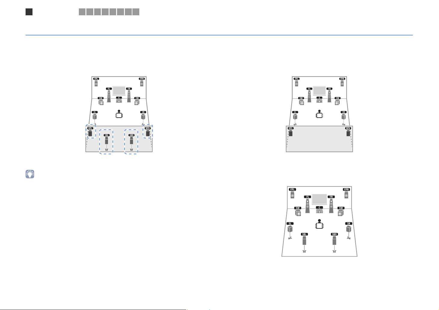
Basic speaker configuration
■ Placing speakers in your room
Depending on the number of speakers, place the speakers and subwoofer (with built-in amplifier) in your room. This section describes the representative speaker layout examples.
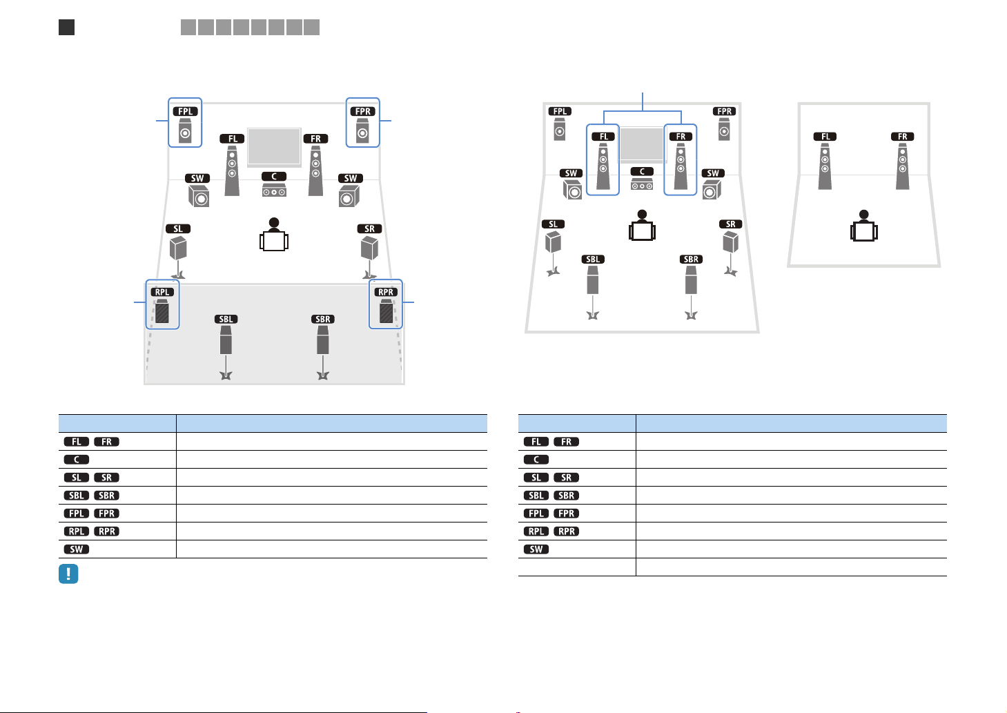
❑ 9.2+2 channel system
(using both surround back and rear presence speakers)
This speaker system brings out the full performance of this unit and allows you to enjoy
a highly-natural stereoscopic sound field with any contents (CINEMA DSP HD³).
• The surround back speakers and rear presence speakers do not produce sounds simultaneously. This unit
automatically switches the speakers to be used depending on a selected CINEMA DSP (p.61).
❑ 9.2 channel system
(using rear presence speakers)
This speaker system uses the front and rear presence speakers to produce a highlynatural stereoscopic sound field (CINEMA DSP HD³), and is suited for enjoying
5.1-channel contents.
❑ 9.2 channel system (using surround back speakers)
This speaker system uses the front presence speakers to produce a natural
stereoscopic sound field, and also allows you to enjoy extended surround sounds using
the surround back speakers.
En 16
Speaker connections
1
2 3 4 5 6 7 8 9
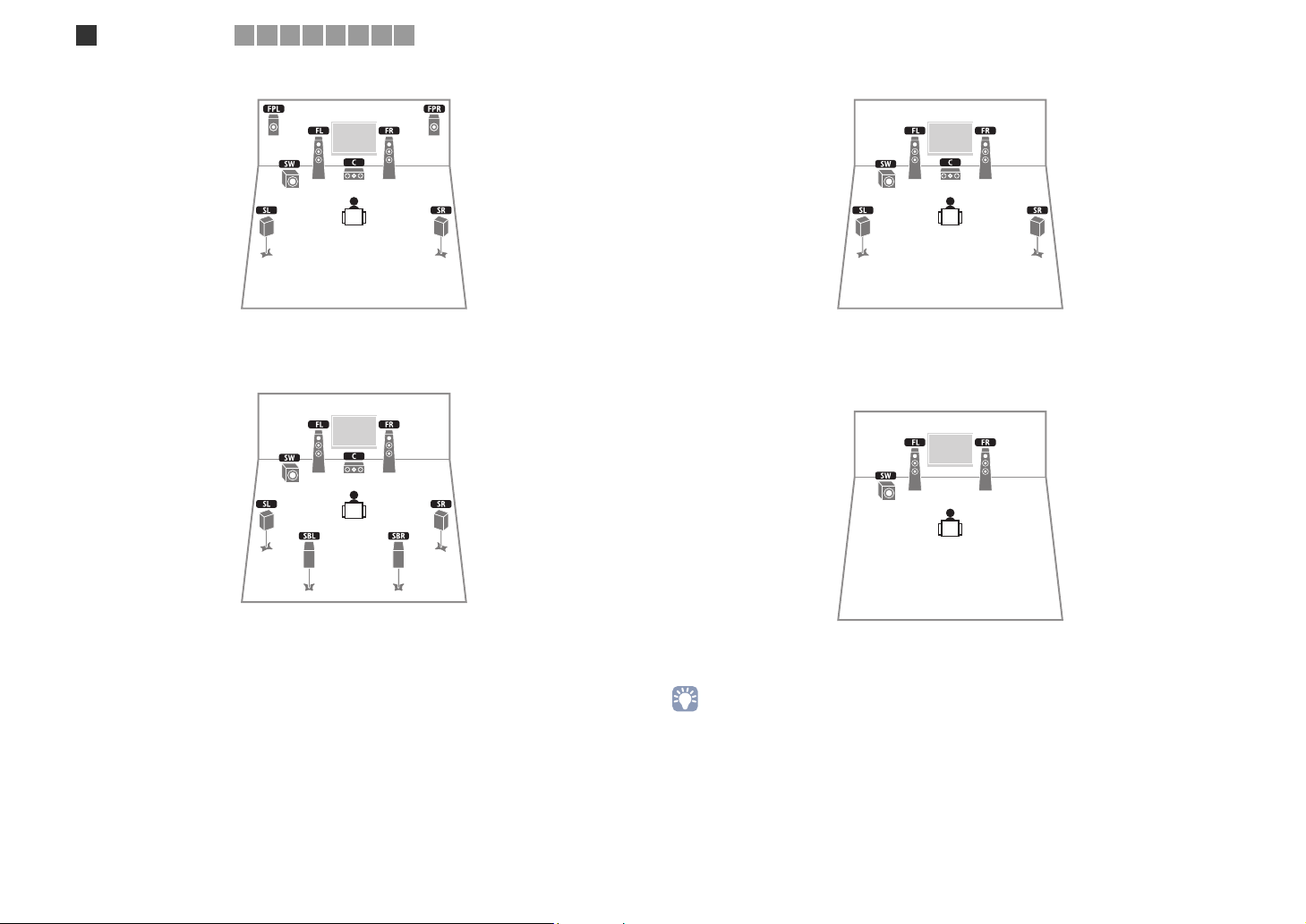
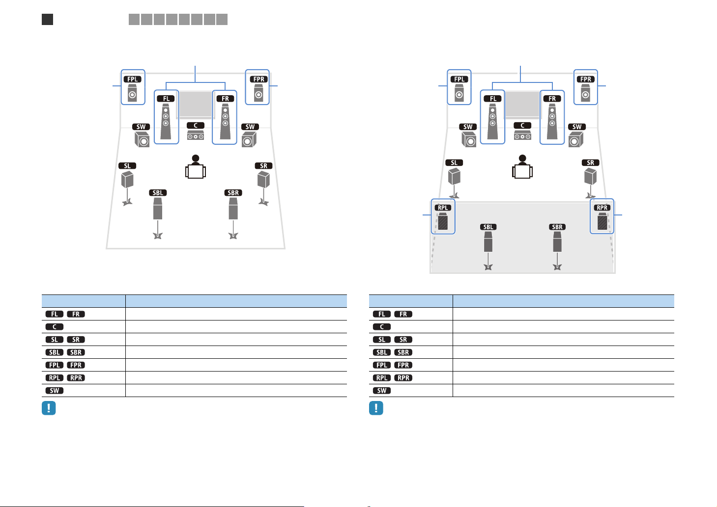
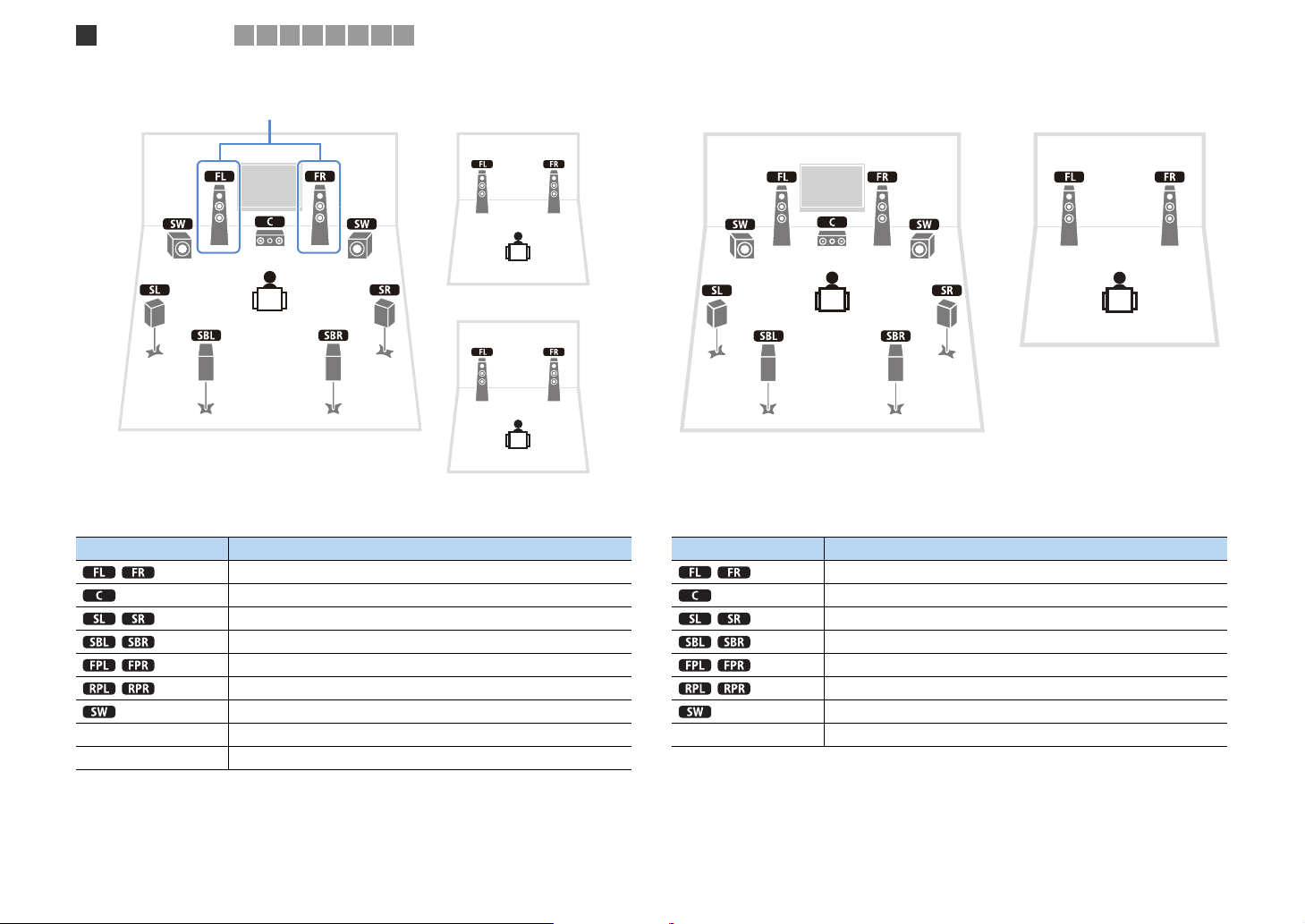
❑ 7.1 channel system (using front presence speakers)
This speaker system uses the front presence speakers to produce a natural
stereoscopic sound field, and is suited for enjoying 5.1-channel contents.
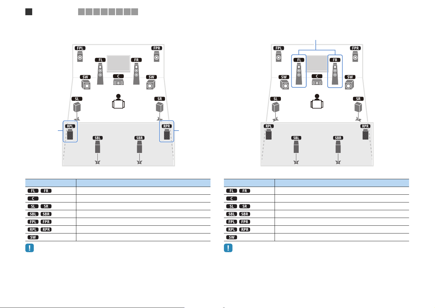
❑ 7.1 channel system (using surround back speakers)
❑ 5.1 channel system
This speaker system creates Virtual Presence Speaker (VPS) using the front, center and
surround speakers to produce a stereoscopic sound field, and is suited for enjoying
5.1-channel contents.
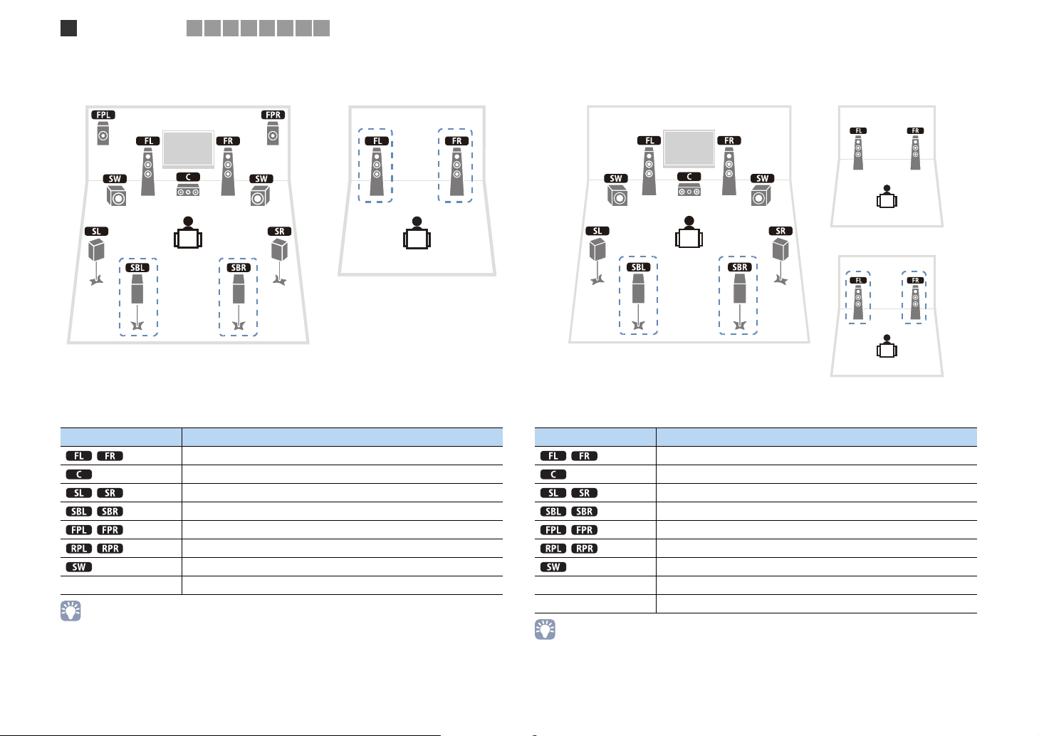
❑ 2.1 channel system
This speaker system creates Virtual Presence Speaker (VPS) using the front, center and
surround speakers to produce a stereoscopic sound field, and also allows you to enjoy
extended surround sounds using the surround back speakers.
Even when no surround speakers are connected, this unit creates the virtual surround
speakers using the front speakers to allow you to enjoy multi-channel surround sound
(Virtual CINEMA DSP).
• Add the center speaker to configure a 3.1-channel system.
En 17

Speaker connections
1
2 3 4 5 6 7 8 9
■ Setting the speaker impedance
This unit is configured for 8-ohm speakers at the factory. When connecting 6-ohm
speakers, set the speaker impedance to “6 Ω MIN”. In this case, you can also use
4-ohm speakers as the front speakers.
Before connecting speakers, connect the supplied power cable to
1
this unit and then to an AC wall outlet.
While holding down STRAIGHT on the front panel, press
2
MAIN ZONE .
MAIN ZONE
Check that “SPEAKER IMP.” is displayed on the front display.
3
DOCK
TAG
SPIMP.-
HD
STEREO
TUNED
PRE
AMP
ZONE
ZONE3ZONE
2
4
OUT 1INOUT 2
ENHANCER
SLEEP
3
HD
Press STRAIGHT to select “6 Ω MIN”.
4
Press MAIN ZONE to set this unit to standby mode and remove the
5
STRAIGHT
SPEAKERIMP.
PARTY
8MIN
MUTE
PL
VOLUME
CL R
SW1SLSW2SW
SBLPL SBRSB PR
DRCADAPTIVE
PR
SR
power cable from the AC wall outlet.
Now you are ready to connect the speakers.
En 18
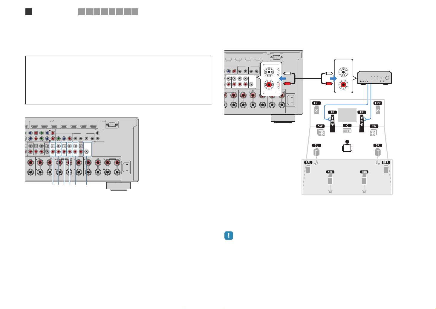
1
2
AUDIO 4
MULTI CH INPUT
ZONE OUT/PRE OUT
AUDIO 3
CENTER
SUBWOOFER
ZONE 2/
F.PRESENCE
ZONE 3/
R.PRESENCE
FRONT
SURROUND SUR. BACK
SPEAKERS
CENTER FRONT
ZONE 2/ZONE 3/R.PRESENCE
SURROUND BACK
BI–AMP
ZONE 2/ZONE 3/F.PRESENCE/
R L
SURROUND
R L
R
R
R
L
L
L
PRE OUT
SUBWOOFER
CENTER
FRONT
SURROUND SUR. BACK
(SINGLE) (FRONT)
(REAR)
EXTRA SP1EXTRA SP2
SINGLE
Speaker connections
1
2 3 4 5 6 7 8 9
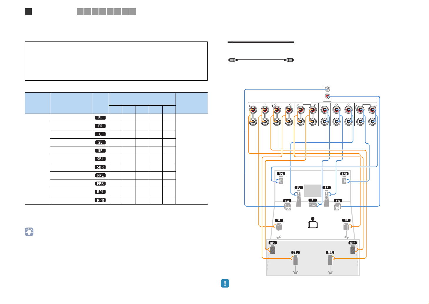
■ Connecting speakers
Connect the speakers placed in your room to this unit.
Caution
• Remove the power cable of this unit from an AC wall outlet and turn off the subwoofer before
connecting the speakers.
• Be careful that the core of the speaker cable does not touch anything or come into contact with the
metal areas of this unit. This may damage this unit or the speakers. If the speaker cables short circuit,
“CHECK SP WIRES” will appear on the front display when this unit is turned on.
Speakers to be connected
Speaker system
Room Speaker type Abbr.
(the number of channels)
9+2 9 7 5 2
Front (L) ●●●●●
Front (R) ●●●●●
Center ●●●●
Surround (L) ●●●●
Surround (R) ●●●●
Main zone
Surround back (L) ● {*1 {*3
Surround back (R) ● { *1 {*3
Front presence (L) ●●{*4
Front presence (R) ●●{*4
Rear presence (L) ● { *2
Rear presence (R) ● {*2
If you have 9 speakers, use two of them as surround back speakers (*1) or rear
presence speakers (*2). If you have 7 speakers, use two of them as surround back
speakers (*3) or front presence speakers (*4).
Power Am p
Assign
(p.107)
Basic (default)
Cables necessary for connection (commercially available)
Speaker cables (x the number of speakers)
+
–
+
–
Audio pin cable (2 for connecting 2 subwoofers)
Connection diagram
Refer to the following diagram and connect the speakers to this unit.
This unit (rear)
• You can also connect up to 2 subwoofers (with built-in amplifier) to this unit. When using 2 subwoofers,
configure the “SWFR Layout” setting (p.109) in the “Setup” menu after connecting the power cable to an AC
wall outlet.
• To use an external power amplifier (Hi-Fi amplifier, etc.) to enhance speaker output, see “Connecting an
external power amplifier” (p.29).
• When using only one surround back speaker, connect it to the SINGLE jack (L side).
En 19

FRONT
FRONT
(
SINGLE
)
CENTER
CENTER
SUR. BACKSURRUND
1
2
FRONT
Speaker connections
1
2 3 4 5 6 7 8 9
❑ Connecting speaker cables
Speaker cables have two wires. One is for connecting the negative (-) terminal of the unit
and the speaker, and the other is for the positive (+) terminal. If the wires are colored to
prevent confusion, connect the black wire to the negative and the other wire to the positive.
a Remove approximately 10 mm of insulation from the ends of the speaker cable, and twist
the bare wires of the cable together firmly.
b Loosen the speaker terminal.
c Insert the bare wires of the cable into the gap on the side (upper right or bottom left) of the
terminal.
d Tighten the terminal.
c
c
+
+ (red)
b
b
-
– (black)
Using a banana plug
a Tighten the speaker terminal.
b Insert a banana plug into the end of the terminal.
Banana plug
b
b
aa
d
d
aa
+
❑ Connecting the subwoofer
Use an audio pin cable to connect the subwoofer.
Audio pin cable
(
FRONT
)
(
REAR
)
SUBWOOFER
En 20
Speaker connections
1
2 3 4 5 6 7 8 9
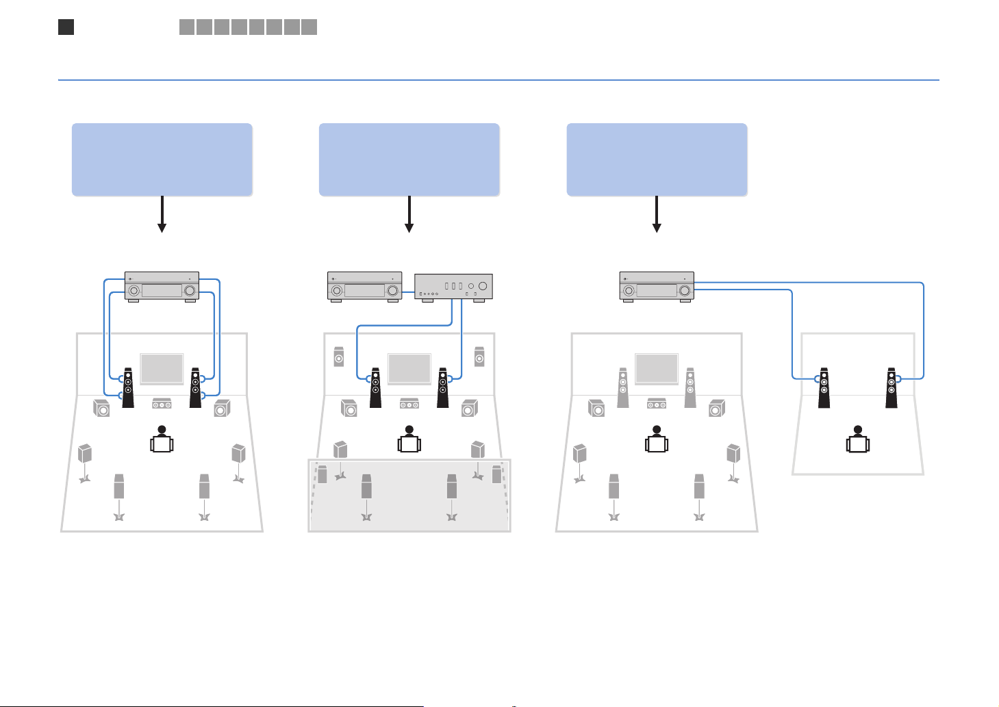
Advanced speaker configuration
In addition to the basic speaker configuration (p.16), this unit also allows you to apply the following speaker configurations to enhance your system.
Using the four internal
amplifiers for front speakers to
have more high-quality sounds
Bi-amp connection Power-amp channel expansion Multi-zone configuration
(Example) (Example) (Example)
Bi-amp
connection
Combining with an external
power amplifier (Hi-Fi
amplifier, etc.) to build an
extended system
External power
amplifier
Using the excess internal
amplifiers for stereo speakers
in another room
Zone2
Main zone
En 21
Speaker connections
1
2 3 4 5 6 7 8 9
■ Available speaker configurations
Main zone
Output
channel
(max)
• When applying one of these configurations, you need to configure the “Power Amp Assign” setting (p.107)
in the “Setup” menu.
• When applying a multi-zone configuration, you can select a zone (Zone2 or Zone3) to be assigned to the
EXTRA SP1~2 jacks in “Power Amp Assign” (p.107) in the “Setup” menu. By default, Zone2 is assigned to
the EXTRA SP1 jacks and Zone3 is assigned to the EXTRA SP2 jacks. The following explanation is based
on the default zone assignments.
Bi-amp
7 { 7ch BI-AMP 22
9 { Front presence 7ch BI-AMP +FP 23
11 {
11 Rear Presence 9ch +RP 24
11 Front 9ch +FRONT 24
11
9 Front +1 room 7ch +FRONT+1ZONE 25
7 Front +2 rooms 5ch +FRONT+2ZONE 26
7 +1 room 7ch +1ZONE 26
9 +1 room 9ch +1ZONE 27
7 +2 rooms 7ch +2ZONE 27
External power
amplifier
(required)
Front presence
Rear presence
Front presence
Rear presence
Multi-zone Power Amp Assign (p.107) Page
7ch BI-AMP FP+RP 23
7ch +FP+RP 25
❑ 7ch BI-AMP
Bi-amp
Speaker Connect to
FRONT and EXTRA SP1 (bi-amp connection)
CENTER
SURROUND
SURROUND BACK
(not used)
(not used)
SUBWOOFER 1~2
En 22
Speaker connections
1
2 3 4 5 6 7 8 9
❑ 7ch BI-AMP +FP ❑ 7ch BI-AMP +FP+RP
Bi-amp
Bi-amp
via external ampvia external amp
Speaker Connect to
FRONT and EXTRA SP1 (bi-amp connection)
CENTER
SURROUND
SURROUND BACK
F.PRESENCE (PRE OUT) via external power amplifier
(not used)
SUBWOOFER 1~2
via external amp
Speaker Connect to
FRONT and EXTRA SP1 (bi-amp connection)
CENTER
SURROUND
SURROUND BACK
F.PRESENCE (PRE OUT) via external power amplifier
R.PRESENCE (PRE OUT) via external power amplifier
SUBWOOFER 1~2
via external ampvia external amp
via external amp
• When this configuration is applied, you cannot utilize the ZONE OUT/PRE OUT jacks for connecting an
external amplifier for Zone2 (p.84).
• When this configuration is applied, you cannot utilize the ZONE OUT/PRE OUT jacks for connecting
external amplifiers for Zone2 and Zone3 (p.84).
En 23
Speaker connections
1
2 3 4 5 6 7 8 9
❑ 9ch +RP ❑ 9ch +FRONT
via external amp
via external amp
Speaker Connect to
FRONT
CENTER
SURROUND
SURROUND BACK
EXTRA SP1
R.PRESENCE (PRE OUT) via external power amplifier
SUBWOOFER 1~2
• When this configuration is applied, you cannot utilize the ZONE OUT/PRE OUT jacks for connecting an
external amplifier for Zone3 (p.84).
via external amp
Speaker Connect to
FRONT (PRE OUT) via external power amplifier
CENTER
SURROUND
SURROUND BACK
EXTRA SP1
EXTRA SP2
SUBWOOFER 1~2
• When this configuration is applied, you cannot utilize the ZONE OUT/PRE OUT jacks for connecting an
external amplifier for Zone3 (p.84).
En 24
Speaker connections
1
2 3 4 5 6 7 8 9
❑ 7ch +FP+RP ❑ 7ch +FRONT+1ZONE
via external amp
via external ampvia external amp
Zone3
via external amp
Speaker Connect to
FRONT
CENTER
SURROUND
SURROUND BACK
F.PRESENCE (PRE OUT) via external power amplifier
R.PRESENCE (PRE OUT) via external power amplifier
SUBWOOFER 1~2
• When this configuration is applied, you cannot utilize the ZONE OUT/PRE OUT jacks for connecting
external amplifiers for Zone2 and Zone3 (p.84).
via external amp
Main zone
Speaker Connect to
FRONT (PRE OUT) via external power amplifier
CENTER
SURROUND
SURROUND BACK
EXTRA SP1
(not used)
SUBWOOFER 1~2
Zone3 speakers EXTRA SP2
En 25
Speaker connections
1
2 3 4 5 6 7 8 9
❑ 5ch +FRONT+2ZONE ❑ 7ch +1ZONE
via external amp
Zone2
Zone2
Main zone
Speaker Connect to
FRONT (PRE OUT) via external power amplifier
CENTER
SURROUND
SURROUND BACK
(not used)
(not used)
SUBWOOFER 1~2
Zone2 speakers EXTRA SP1
Zone3 speakers EXTRA SP2
Main zone
Zone3
Speaker Connect to
FRONT
CENTER
SURROUND
SURROUND BACK
(not used)
(not used)
SUBWOOFER 1~2
Zone2 speakers EXTRA SP1
En 26
Speaker connections
1
2 3 4 5 6 7 8 9
❑ 9ch +1ZONE ❑ 7ch +2ZONE
Zone3
Zone2
Main zone
Speaker Connect to
FRONT
CENTER
SURROUND
SURROUND BACK
EXTRA SP1
(not used)
SUBWOOFER 1~2
Zone3 speakers EXTRA SP2
• When Zone3 output is enabled (p.87), the surround back speakers in the main zone do not output sound.
Main zone
Zone3
Speaker Connect to
FRONT
CENTER
SURROUND
SURROUND BACK
(not used)
(not used)
SUBWOOFER 1~2
Zone2 speakers EXTRA SP1
Zone3 speakers EXTRA SP2
• When Zone3 output is enabled (p.87), the surround back speakers in the main zone do not output sound.
En 27
SPEAKERS
S
S
Speaker connections
1
■
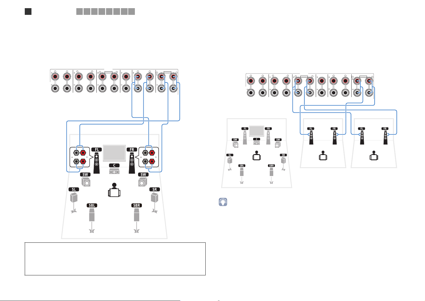
Connecting front speakers that support bi-amp connections
2 3 4 5 6 7 8 9
When using front speakers that support bi-amp connections, connect them to the
FRONT jacks and EXTRA SP1 jacks.
To enable the bi-amp function, configure the “Power Amp Assign” setting (p.107) in the
“Setup” menu after connecting the power cable to an AC wall outlet.
■ Connecting Zone2/3 speakers
When using Zone2/3 speakers, connect them to the EXTRA SP1~2 jacks.
To utilize the EXTRA SP1~2 jacks for Zone2/3 speakers, configure the “Power Amp
Assign” setting (p.107) in the “Setup” menu after connecting the power cable to an AC
wall outlet.
This unit (rear)
SURROUND
R L
SURROUND BACK
R L
SINGLE
ZONE 2/ZONE 3/R.PRESENCE
R
CENTER FRONT
L
ZONE 2/ZONE 3/F.PRESENCE/
R
BI–AMP
L
EXTRA SP1EXTRA SP2
R
L
This unit (rear)
SURROUND
R L
SURROUND BACK
R L
SINGLE
PEAKER
ZONE 2/ZONE 3/R.PRESENCE
R
CENTER FRONT
L
ZONE 2/ZONE 3/F.PRESENCE/
R
BI–AMP
L
EXTRA SP1EXTRA SP2
R
L
Zone2 Zone3
Main zone
• You can select a zone (Zone2 or Zone3) to be assigned to the EXTRA SP1~2 jacks in “Power Amp Assign”
(p.107) in the “Setup” menu. By default, Zone2 is assigned to the EXTRA SP1 jacks and Zone3 is assigned
to the EXTRA SP2 jacks.
• You can also connect Zone2, Zone3 and Zone4 speakers using an external amplifier (p.84).
Caution
• Before making bi-amp connections, remove any brackets or cables that connect a woofer with a
tweeter. Refer to the instruction manual of the speakers for details. When not making bi-amp
connections, make sure that the brackets or cables are connected before connecting the speaker
cables.
En 28
O
/
C
R
Speaker connections
1
2 3 4 5 6 7 8 9
■ Connecting an external power amplifier
When using an external power amplifier to enhance speaker output, connect the input
jacks of the power amplifier to the PRE OUT jacks of this unit. The same channel signals
are output from the PRE OUT jacks as from their corresponding SPEAKERS terminals.
Caution
• To prevent the generation of loud noises or abnor mal sounds, make sure the followings before making
connections.
- Remove the power cable of this unit and turn off the external power amplifier before connecting them.
- When using the PRE OUT jacks, do not connect speakers to the corresponding SPEAKERS
terminals.
- When using an external amplifier that does not have the volume control bypass, do not connect other
devices (except this unit) to the amplifier.
This unit (rear)
AV 1
AV 2 AV 3 AV 4 AV 5 AV 6 AV 7
2
(1 BD/DVD)
COMPONENT VIDEO
B PR
YPB PR
P
AV 3
C
D
FRONT
L
MULTI CH INPUT
SURROUND SUR. BACK
R L
AV 4
SURROUND BACK
CENTER
SUBWOOFER
SINGLE
ZONE OUT/PRE OUT
ZONE 2/
F.PRESENCE
ZONE 3/
R.PRESENCE
R
4
OUND
HDMI
MONITOR OUT/ZONE OUT
YPB PR
FRONT
SPEAKERS
ZONE 2/ZONE 3/R.PRESENCE
PRE OUT
SURROUND SUR. BACK
L
REMOTE
1
IN OUT2IN OUT
(SINGLE) (FRONT)
1
2
(REAR)
CENTER
SUBWOOFER
CENTER FRONT
R
TRIGGER
OUT
+12V 0.1A MAX.
L
1
2
R
RS-232C
ZONE 2/ZONE 3/F.PRESENCE/
BI–AMP
EXTRA SP1EXTRA SP2
AC IN
L
(Example)
Connecting front speakers via an external power amplifier
PRE OUT (FRONT) jacks
I
AV 4 AV 5 AV 6 AV 7
P
B PR
(SINGLE) (FRONT)
PRE OUT
SURROUND SUR. BACK
L
REMOTE
1
IN OUT2IN OUT
1
2
(REAR)
CENTER
SUBWOOFER
CENTER FRONT
ONITOR OUT/ZONE OUT
FRONT
E
SPEAKERS
2/ZONE 3/R.PRESENCE
This unit (rear)
R
TRIGGER
OUT
+12V 0.1A MAX.
L
1
2
FRONT
R
RS-232C
PR
ZONE 2/ZONE 3/F.PRESENCE/
BI–AMP
EXTRA SP1EXTRA SP2
SU
Main input jack
MAIN IN
L
R
AC IN
L
L
R
Amplifier with volume
control bypass
(A-S2000, etc.)
3 41 2 56
1 F.PRESENCE jacks
Output front presence channel audio signals or Zone2 audio signals depending on the “Power
Amp Assign” setting (p.107).
2 R.PRESENCE jacks
Output rear presence channel audio signals or Zone3 audio signals depending on the “Power
Amp Assign” setting (p.107).
About external power amplifiers
We recommend using power amplifiers that meet the following conditions.
- With unbalanced inputs
- With volume control bypass (or without volume control circuit)
- Output power: 100 W (8Ω) or more
3 FRONT jacks
Output front channel audio signals
4 SURROUND jacks
Output surround channel audio signals
5 SUR. BACK jacks
Output surround back channel audio signals. When using only one external amplifier for the
surround back channel, connect it to the SINGLE jack (L side).
• When using an external amplifier that does no have the volume control bypass, turn up the volume of the
external amplifier enough and fix it.
6 CENTER jack
Outputs center channel audio signals.
En 29
Input/output jacks and cables
COMPONEN
AV 1
A
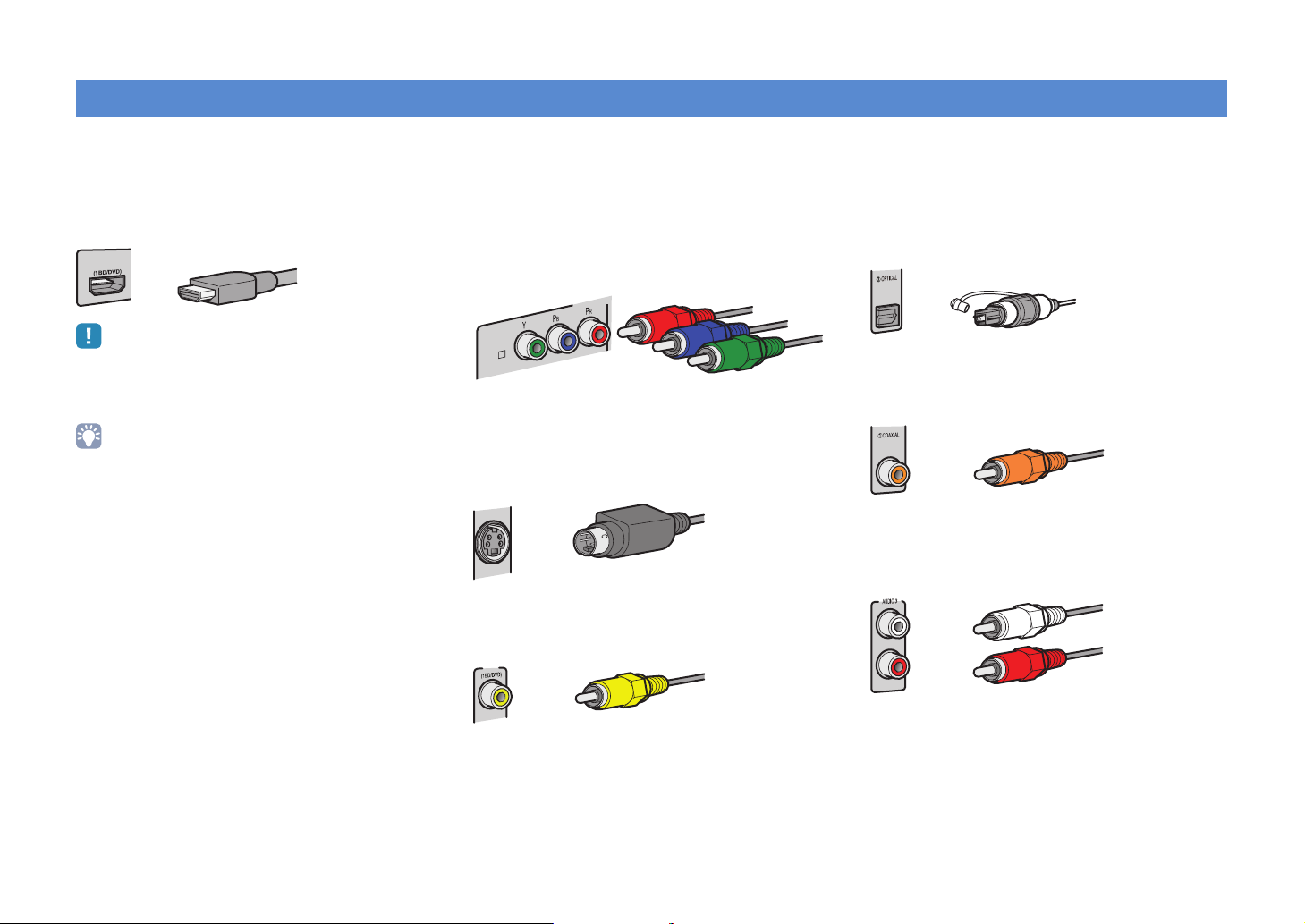
■ Video/audio jacks
❑ HDMI jacks
Transmit digital video and digital sound through a single
jack. Use an HDMI cable.
AV 1
• Use a 19-pin HDMI cable with the HDMI logo. We recommend using
a cable less than 5.0 m long to prevent signal quality degradation.
• To connect a device that has a DVI jack, an HDMI/DVI-D cable is
required.
• The HDMI jacks of this unit support the HDMI Control, Audio Return
Channel (ARC), and 3D video transmission (through output)
features.
HDMI cable
■ Video jacks
❑ COMPONENT VIDEO jacks
Transmit video signals separated into three
components: luminance (Y), chrominance blue (PB),
and chrominance red (PR). Use a component video
cable with three plugs.
Component video cable
❑ S VIDEO jack
Transmits S-video signals that include luminance (Y)
and chrominance (C) components. Use an S-video
cable.
S-video cable
❑ VIDEO jacks
Transmit analog video signals. Use a video pin cable.
AV 1
Video pin cable
■ Audio jacks
❑ OPTICAL jacks
Transmit digital audio signals. Use a digital optical
cable. Remove the tip protector (if available) before
using the cable.
Digital Optical cable
❑ COAXIAL jacks
Transmit digital audio signals. Use a digital coaxial
cable.
Digital coaxial cable
❑ AUDIO jacks
Transmit analog stereo audio signals. Use a stereo pin
cable.
Stereo pin cable
En 30
 Loading...