

Page 1

RX-V2500
AV Receiver
Ampli-tuner audio-vidéo
GB
OWNER'S MANUAL
MODE D'EMPLOI
BEDIENUNGSANLEITUNG
BRUKSANVISNING
MANUALE DI ISTRUZIONI
MANUAL DE INSTRUCCIONES
GEBRUIKSAANWIJZING
Page 2

CAUTION: READ THIS BEFORE OPERATING YOUR UNIT.
CAUTION: READ THIS BEFORE OPERATING YOUR UNIT.
1 To assure the finest performance, please read this manual
carefully. Keep it in a safe place for future reference.
2 Install this sound system in a well ventilated, cool, dry, clean
place — away from direct sunlight, heat sources, vibration,
dust, moisture, and/or cold. Allow ventilation space of at least
30 cm on the top, 20 cm on the left and right, and 20 cm on
the back of this unit.
3 Locate this unit away from other electrical appliances, motors,
or transformers to avoid humming sounds.
4 Do not expose this unit to sudden temperature changes from
cold to hot, and do not locate this unit in an environment with
high humidity (i.e. a room with a humidifier) to prevent
condensation inside this unit, which may cause an electrical
shock, fire, damage to this unit, and/or personal injury.
5 Avoid installing this unit where foreign object may fall onto
this unit and/or this unit may be exposed to liquid dripping or
splashing. On the top of this unit, do not place:
– Other components, as they may cause damage and/or
discoloration on the surface of this unit.
– Burning objects (i.e. candles), as they may cause fire,
damage to this unit, and/or personal injury.
– Containers with liquid in them, as they may fall and liquid
may cause electrical shock to the user and/or damage to
this unit.
6 Do not cover this unit with a newspaper, tablecloth, curtain,
etc. in order not to obstruct heat radiation. If the temperature
inside this unit rises, it may cause fire, damage to this unit,
and/or personal injury.
7 Do not plug in this unit to a wall outlet until all connections
are complete.
8 Do not operate this unit upside-down. It may overheat,
possibly causing damage.
9 Do not use force on switches, knobs and/or cords.
10 When disconnecting the power cable from the wall outlet,
grasp the plug; do not pull the cable.
11 Do not clean this unit with chemical solvents; this might
damage the finish. Use a clean, dry cloth.
12 Only voltage specified on this unit must be used. Using this
unit with a higher voltage than specified is dangerous and may
cause fire, damage to this unit, and/or personal injury.
YAMAHA will not be held responsible for any damage
resulting from use of this unit with a voltage other than
specified.
13 To prevent damage by lightning, disconnect the power cable
from the wall outlet during an electrical storm.
14 Do not attempt to modify or fix this unit. Contact qualified
YAMAHA service personnel when any service is needed. The
cabinet should never be opened for any reasons.
15 When not planning to use this unit for long periods of time
(i.e. vacation), disconnect the AC power plug from the wall
outlet.
16 Be sure to read the “TROUBLESHOOTING” section on
common operating errors before concluding that this unit is
faulty.
17 Before moving this unit, press STANDBY/ON to set this unit
in the standby mode, and disconnect the AC power plug from
the wall outlet.
18 VOLTAGE SELECTOR (Asia and General models only)
The VOLTAGE SELECTOR on the rear panel of this unit
must be set for your local main voltage BEFORE plugging
into the AC main supply. Voltages are:
General model.............AC 110/120/220/230–240 V, 50/60 Hz
Asia model ................................ AC 220/230–240 V, 50/60 Hz
WARNING
TO REDUCE THE RISK OF FIRE OR ELECTRIC
SHOCK, DO NOT EXPOSE THIS UNIT TO RAIN
OR MOISTURE.
This unit is not disconnected from the AC power
source as long as it is connected to the wall outlet, even
if this unit itself is turned off. This state is called the
standby mode. In this state, this unit is designed to
consume a very small quantity of power.
■ For U.K. customers
If the socket outlets in the home are not suitable for the
plug supplied with this appliance, it should be cut off and
an appropriate 3 pin plug fitted. For details, refer to the
instructions described below.
Note
The plug severed from the mains lead must be destroyed, as a
plug with bared flexible cord is hazardous if engaged in a live
socket outlet.
■ Special Instructions for U.K. Model
IMPORTANT
THE WIRES IN MAINS LEAD ARE COLOURED IN
ACCORDANCE WITH THE FOLLOWING CODE:
Blue: NEUTRAL
Brown: LIVE
As the colours of the wires in the mains lead of this
apparatus may not correspond with the coloured
markings identifying the terminals in your plug,
proceed as follows:
The wire which is coloured BLUE must be connected
to the terminal which is marked with the letter N or
coloured BLACK. The wire which is coloured
BROWN must be connected to the terminal which is
marked with the letter L or coloured RED.
Making sure that neither core is connected to the earth
terminal of the three pin plug.
Page 3

CONTENTS
INTRODUCTION
FEATURES............................................................. 2
GETTING STARTED............................................ 3
Supplied accessories .................................................. 3
Installing batteries in the remote controls.................. 3
CONTROLS AND FUNCTIONS ......................... 4
Front panel ................................................................. 4
Remote control........................................................... 6
Using the remote control ........................................... 8
Front panel display .................................................... 9
Rear panel ................................................................ 11
PREPARATION
SPEAKER SETUP ............................................... 12
Speaker placement ................................................... 12
Speaker connections ................................................ 13
CONNECTIONS .................................................. 17
Before connecting components................................ 17
Connecting video components................................. 18
Connecting audio components................................. 21
Connecting the antennas .......................................... 23
Connecting the power cable..................................... 24
Speaker impedance setting ...................................... 25
Turning on the power............................................... 25
AUTO SETUP....................................................... 26
Introduction.............................................................. 26
Optimizer microphone setup.................................... 26
Starting the setup ..................................................... 27
Confirming the results ............................................. 29
BASIC OPERATION
PLAYBACK.......................................................... 32
Basic operations....................................................... 32
Selecting sound field programs ............................... 33
Additional operations............................................... 34
Selecting input modes.............................................. 39
TUNING ................................................................ 40
Automatic and manual tuning.................................. 40
Presetting stations .................................................... 41
Selecting preset stations........................................... 43
Exchanging preset stations ...................................... 43
Receiving RDS stations ........................................... 44
Changing the RDS mode ......................................... 44
PTY SEEK function ................................................ 45
EON function........................................................... 46
RECORDING ....................................................... 47
SOUND FIELD PROGRAMS
SOUND FIELD PROGRAM
DESCRIPTIONS...............................................48
For movie/video sources.......................................... 48
For music sources .................................................... 51
ADVANCED OPERATION
ADVANCED OPERATIONS ..............................52
Using the sleep timer ............................................... 52
SYSTEM OPTIONS .............................................53
Changing parameter settings ................................... 55
Input Select .............................................................. 56
Manual setup: Sound ............................................... 58
Manual setup: Basic................................................. 61
Manual setup: Option .............................................. 65
System Memory....................................................... 67
REMOTE CONTROL FEATURES ...................69
Control area ............................................................. 69
Setting remote control codes ................................... 70
Programming codes from other remote controls
(Learn) ................................................................. 72
Changing source names in the display window....... 74
Using the Macro feature .......................................... 75
Clearing function sets .............................................. 77
Clearing individual functions .................................. 78
Controlling each component.................................... 80
ZONE 2/ZONE 3
(U.S.A., CANADA, U.K., EUROPE AND
AUSTRALIA MODELS ONLY) .....................81
Zone 2/Zone 3 connections...................................... 81
Remote controlling Zone 2/Zone 3.......................... 82
FRONT PANEL DISPLAY MENUS ..................84
Advanced setup menu.............................................. 84
Front panel display system options menu................ 85
ADDITIONAL INFORMATION
EDITING SOUND FIELD PARAMETERS ......89
What is a sound field? ............................................. 89
Changing parameter settings ................................... 89
SOUND FIELD PARAMETER
DESCRIPTIONS...............................................90
TROUBLESHOOTING .......................................95
GLOSSARY.........................................................100
Audio formats ........................................................ 100
Sound field programs............................................. 101
Audio information ................................................. 102
Video signal information ....................................... 103
PARAMETRIC EQUALIZER
INFORMATION .............................................104
SPECIFICATIONS.............................................105
PREPARATIONINTRODUCTION
OPERATION
BASIC
SOUND FIELD
PROGRAMS
OPERATION
ADVANCED
INFORMATION
ADDITIONAL
English
1
Page 4
FEATURES
FEATURES
Built-in 7-channel power amplifier
◆ Minimum RMS Output Power
(0.04% THD, 20 Hz – 20 kHz, 8 Ω)
Front: 130 W + 130 W
Center: 130 W
Surround: 130 W + 130 W
Surround Back: 130 W + 130 W
Sound field features
◆ Proprietary YAMAHA technology for the creation of
sound fields
◆ THX Select
◆ Dolby Digital/Dolby Digital EX decoder
◆ DTS/DTS-ES Matrix 6.1, Discrete 6.1,
DTS Neo:6 decoder, DTS 96/24
◆ Dolby Pro Logic/Dolby Pro Logic II/Dolby Pro Logic
IIx decoder
◆ Virtual CINEMA DSP
◆ SILENT CINEMA
™
Sophisticated AM/FM tuner
◆ 40-station random access preset tuning
◆ Automatic preset tuning
◆ Preset station shifting capability (preset editing)
◆ RDS: Radio Data System receiving capability
(U.K. and Europe models only)
Other features
◆ YPAO: YAMAHA Parametric Room Acoustic
Optimizer for automatic speaker setup
◆ 192-kHz/24-bit D/A converter
◆ GUI (graphical user interface) menus that allow you to
optimize this unit to suit your individual audio/video
system
◆ 6 or 8-channel additional input jacks for discrete multi
channel input
◆ Short message function
◆ PURE DIRECT for pure fidelity sound with analog and
PCM sources
◆ S-video signal input/output capability
◆ Component video input/output capability
◆ Video signal conversion (composite video ↔
S-video → component video) capability for monitor
out
◆ Optical and coaxial digital audio signal jacks
◆ Sleep timer
◆ Cinema and music night listening mode
◆ Remote control with preset remote control codes and
learning/macro capability
◆ Zone 2/Zone 3 custom installation facility
(U.S.A., Canada, U.K., Europe and Australia models
only)
• y indicates a tip for your operation.
• Some operations can be performed by using either the buttons on the main unit or on the remote control. In cases when the button
names differ between the main unit and the remote control, the button name on the remote control is given in parentheses.
• This manual is printed prior to production. Design and specifications are subject to change in part as a result of improvements, etc. In
case of differences between the manual and product, the product has priority.
Manufactured under license from Dolby Laboratories.
“Dolby”, “Pro Logic”, “Surround EX”, and the double-D symbol
are trademarks of Dolby Laboratories.
“SILENT CINEMA” is a trademark of YAMAHA
CORPORATION.
“DTS”, “DTS-ES”, “Neo:6” and “DTS 96/24” are trademarks of
Digital Theater Systems, Inc.
THX and the THX logo are registered trademarks of THX Ltd.
Surround EX is a jointly developed technology of THX and
Dolby Laboratories, Inc. and is a trademark of Dolby
Laboratories, Inc. All rights reserved. Used under authorization.
We Want You Listening For A Lifetime
YAMAHA and the Electronic Industries Association’s Consumer Electronics Group want you to get the most out of your
equipment by playing it at a safe level. One that lets the sound come through loud and clear without annoying blaring or
distortion – and, most importantly, without affecting your sensitive hearing. Since hearing damage from loud sounds is
often undetectable until it is too late, YAMAHA and the Electronic Industries Association’s Consumer Electronics Group
recommend you to avoid prolonged exposure from excessive volume levels.
2
Page 5
GETTING STARTED
1
3
2
GETTING STARTED
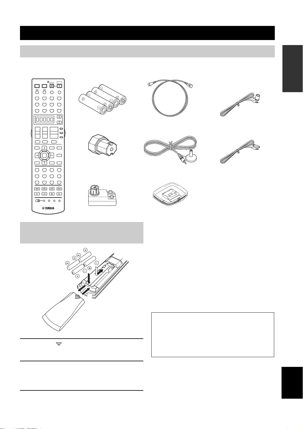
Supplied accessories
Please check that you received all of the following parts.
Remote control Batteries (4)
POWER POWER POWER
A
PHONO TUNER CD
V-AUX
DTV DVR/VCR2VCR 1 DVD
+
TV VOL
–
TV MUTE TV INPUT
TOP
TITLE
RETURN
STEREO
THX
5678
1
90
FREQ/RDS EON MODE PTY SEEK START
REC
DISC SKIP
SYSTEM
STANDBY
AVTV
SLEEP
INPUT MODE
B
MULTI CH IN
CBL/SAT MD/TAPE
CD-R
SELECT
AMP
+
+
SOURCE
VOL
CH
TV
–
–
A/B/C/D/E
MUTE
PURE DIRECT
EXIT
MENU
NIGHT
ENTER
AUDIO
STRAIGHT
DISPLAY
EFFECT
MUSIC ENTERTAIN MOVIE
3421
STANDARD SELECT EXTD. SUR
2B
SPEAKERSMEMORY
A
ENT.
+10
CLEAR
LEARN
MACROONOFF
RE–NAME
(AAA, LR03)
Speaker terminal wrench
75-ohm/300-ohm
antenna adapter
(U.K. model only)
Power cable
Optimizer microphone
AM loop antenna
INTRODUCTION
Indoor FM antenna
(U.S.A., Canada, China,
Korea, Asia and General
models)
Indoor FM antenna
(U.K., Europe and
Australia models)
Installing batteries in the remote
controls
1 Press the part and slide the battery
compartment cover off.
2 Insert four supplied batteries (AAA, LR03)
according to the polarity markings on the
inside of the battery compartment.
3 Slide the cover back until it snaps into place.
Notes on batteries
• Change all of the batteries if you notice conditions such as the
operation range of the remote control decreases, the indicator
does not flash, or its light or display window become dim.
• Do not use old batteries together with new ones.
• Do not use different types of batteries (such as alkaline and
manganese batteries) together. Read the packaging carefully as
these different types of batteries may have the same shape and
color.
• If the batteries have leaked, dispose of them immediately. Avoid
touching the leaked material or letting it come into contact with
clothing, etc. Clean the battery compartment thoroughly before
installing new batteries.
• Do not throw away batteries with general house waste; dispose
of them correctly in accordance with your local regulations.
If the remote control is without batteries for more than
2 minutes, or if exhausted batteries remain in the
remote control, the contents of the memory may be
cleared. When the memory is cleared, insert new
batteries, set up the remote control code and program
any acquired functions that may have been cleared.
English
3
Page 6
CONTROLS AND FUNCTIONS
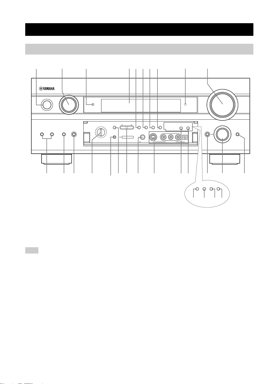
Front panel
CONTROLS AND FUNCTIONS
1 24 0
INPUT
STANDBY
/ON
SPEAKERS
A
MULTI CHBINPUT MODE
INPUT
ABC EF
3 9
PURE DIRECT
A/B/C/D/E
OPTIMIZER
MIC
PRESET/
TUNING
YPAO
G
SOURCE/
REMOTE
MD/TAPEDVD
DTV
CD-R
VCR 1
DVR/
VCR2
REC OUT/ZONE 2
TUNER
CD
CBL/SAT
DHI LKJ
6785
PRESET
/TUNING
EDIT
SILENT CINEMA
PHONES
FM/AM
MEMORY
MAN'L/AUTO FM AUTO/MAN'L MONO
S VIDEO VIDEO L
TUNING
MODE
VIDEO AUX
ZONE ON/OFF
MAIN ZONE 2
AUDIO R OPTICAL
TONE CONTROL STRAIGHT
RDS MODE
/FREQ
EON PTY SEEK
PQRO
(U.K. and Europe models only)
(U.S.A. model)
VOLUME
PROGRAM
EFFECT
M N
MODE START
1 STANDBY/ON
Turns on this unit or sets it to the standby mode. When you
turn on this unit, you will hear a click and there will be a 6
to 7 second delay before this unit can reproduce sound.
Note
In standby mode, this unit consumes a small amount of power in
order to receive infrared-signals from the remote control.
2 INPUT selector
Selects the input source you want to listen to or watch.
3 PURE DIRECT
Turns on or off the PURE DIRECT mode. Lights up when
turned on (see page 37).
4 Front panel display
Shows information about the operational status of this
unit.
5 PRESET/TUNING EDIT
Switches the function of PRESET/TUNING l / h
between selecting preset station numbers and tuning.
4
6 FM/AM
Switches the reception band between FM and AM.
7 MEMORY (MAN’L/AUTO FM)
Stores a station in the memory. Hold down this button for
more than 3 seconds to start automatic preset tuning.
8 TUNING MODE (AUTO/MAN’L MONO)
Switches the tuning mode between automatic (“AUTO”
indicator on) and manual (“AUTO” indicator off).
9 Remote control sensor
Receives signals from the remote control.
0 VOLUME
Controls the output level of all audio channels.
This does not affect the REC OUT level.
A SPEAKERS A/B
Turn on or off the set of front speakers connected to the A
and/or B terminals on the rear panel at each time the
corresponding button is pressed.
Page 7
CONTROLS AND FUNCTIONS
B MULTI CH INPUT
Selects the source connected to the MULTI CH INPUT
jacks. When selected, the MULTI CH INPUT source takes
priority over the source selected with INPUT (or the input
selector buttons on the remote control).
C INPUT MODE
Sets the priority (AUTO, DTS, ANALOG) for the type of
signals received when one component is connected to two
or more of this unit’s input jacks (see page 39).
D REC OUT/ZONE 2
(U.S.A., Canada, U.K., Europe and Australia
models only)
Selects the source you want to direct to the audio/video
recorder and ZONE 2 outputs independently of the source
you are listening to or watching in the main room. When
set to the SOURCE/REMOTE position, the input source is
directed to all outputs. The source in Zone 2 and the
source you record are always identical
REC OUT (other models)
Selects the source you want to direct to the audio/video
recorder independent of the source you are listening to or
watching. When set to the SOURCE/REMOTE position,
the input source is directed to all outputs.
E OPTIMIZER MIC jack
Use to connect and input audio signals from the supplied
microphone for use with the AUTO SETUP function (see
page 26).
F A/B/C/D/E
Selects one of the 5 preset station groups (A to E).
G PRESET/TUNING l / h
Selects preset station number 1 to 8 when the colon (:) is
displayed next to the band indication in the front panel
display.
Selects the tuning frequency when the colon (:) is not
displayed.
H PHONES (SILENT CINEMA) jack
Outputs audio signals for private listening with
headphones. When you connect headphones, no signals
are output to the PRE OUT jacks or to the speakers.
All Dolby Digital and DTS audio signals are mixed down
to the front left and right channels.
I VIDEO AUX jacks
Input audio and video signals from an external source such
as a game console. To reproduce source signals from these
jacks, select V-AUX as the input source.
J ZONE ON/OFF (MAIN)
(U.S.A., Canada and Australia models only)
Turns the main unit on or to the standby mode (see
page 83).
K ZONE ON/OFF (ZONE 2)
(U.S.A., Canada and Australia models only)
Turns Zone 2 on or to the standby mode (see page 83).
L TONE CONTROL
Use to adjust the bass/treble balance for the front left/right
and center channels (see page 34).
M PROGRAM
Use to select sound field programs or adjust bass/treble
balance (in conjunction with TONE CONTROL).
N STRAIGHT/EFFECT
Switches the sound fields off or on. When STRAIGHT is
selected, input signals (2-channel or multi-channel) are
output directly from their respective speakers without
effect processing.
■ U.K. and Europe models only
O RDS MODE/FREQ
Press this button when the unit is receiving an RDS station
to cycle the display mode between the PS mode, PTY
mode, RT mode, CT mode (if the station offers those RDS
data service) and/or the frequency display mode (see
page 44).
P EON
Press this button to select a radio program type (NEWS,
INFO, AFFAIRS, SPORT) to tune in automatically (see
page 46).
Q PTY SEEK MODE
Press this button to set the unit to the PTY SEEK mode
(see page 45).
R PTY SEEK START
Press this button to begin searching for a station after the
desired program type has been selected in the PTY SEEK
mode (see page 45).
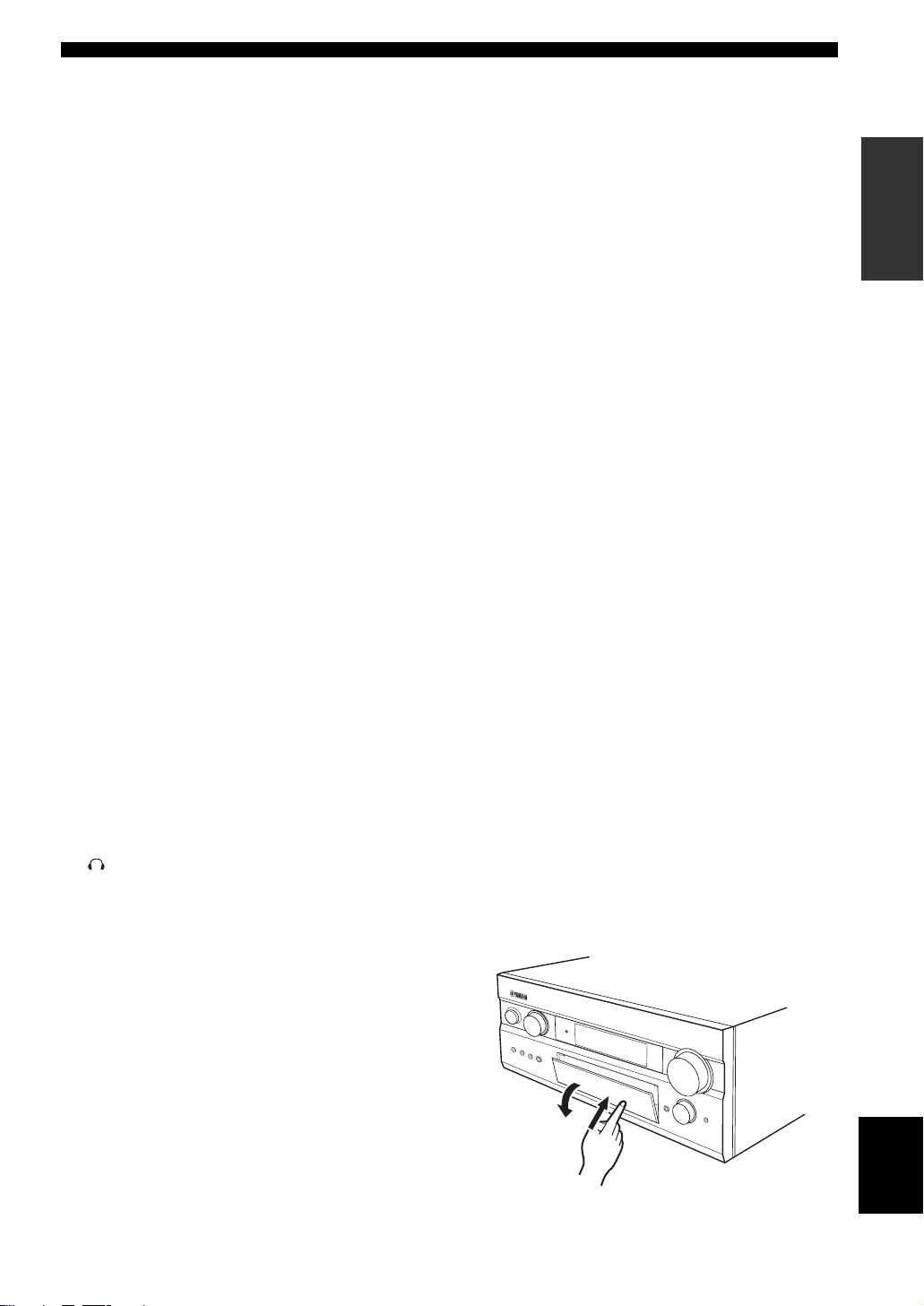
■ Opening and closing the front panel
door
When you want to use the controls behind the front panel
door, open the door by gently pressing on the lower part of
the panel. Keep the door closed when not using these
controls.
INTRODUCTION
English
To open, press gently on the lower part of the panel.
5
Page 8
CONTROLS AND FUNCTIONS
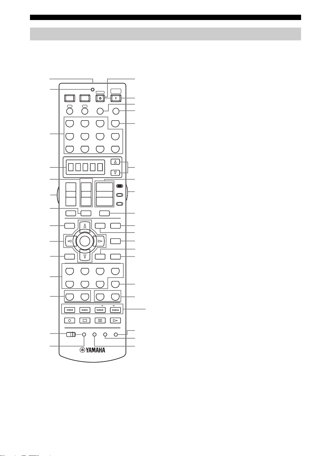
Remote control
This section describes the function of each control on the
remote control used to control this unit. To operate other
components, see “REMOTE CONTROL FEATURES” on
page 69.
1
2
POWER POWER POWER
AVTV
A
B
STANDBY
INPUT MODE
SYSTEM
SLEEP
E
F
G
H
PHONO TUNER CD
MULTI CH IN
I
V-AUX
3
CBL/SAT MD/TAPE
DTV DVR/VCR2VCR 1 DVD
4
5
6
7
8
9
0
A
B
C
PRESET
+
+
CH
TV VOL
–
–
A/B/C/D/E
TV MUTE TV INPUT
TOP
TITLE
ENTER
RETURN
STEREO
MUSIC ENTERTAIN MOVIE
THX
STANDARD SELECT
5678
1
2 B
90
FREQ/RDS EON MODE PTY SEEK START
REC
DISC SKIP
LEARN
MACROONOFF
D
1 Infrared window
Outputs infrared control signals. Aim this window at the
component you want to operate.
2 Transmission indicator
Flashes while the remote control is sending signals.
EXIT
MENU
DISPLAY
3421
A
+10
+
VOL
–
MUTE
SPEAKERSMEMORY
CLEAR
CD-R
SELECT
AMP
SOURCE
TV
PURE DIRECT
NIGHT
AUDIO
STRAIGHT
EFFECT
EXTD. SUR
ENT.
RE–NAME
J
K
L
M
N
O
P
Q
R
S
t
X
U
V
W
3 Input selector buttons
Select the input source and change the control area.
4 Display window
Shows the name of the selected source component that
you can control.
5 PRESET +/–
Selects preset station numbers when this unit is in tuner
mode.
6 LIGHT button
Press to light up remote control buttons and display
window.
7 A/B/C/D/E
Selects preset groups when this unit is in tuner mode.
8 TOP
Selects the graphical user interface (GUI) mode for your
video monitor.
9 Cursor buttons k / n / l / h / ENTER
Use to select and adjust DSP program parameters or GUI
menu items.
0 RETURN
Returns to the upper directory when in the front panel
display menu mode.
A Sound field program/Numeric buttons
Use to select sound field programs or input numbers.
Use numbers 1 through 8 to select preset stations when
this unit is in tuner mode.
B MEMORY 1/2
Use to recall favorite sound field programs, YPAO settings
or additional preset stations (see page 68).
C MACRO ON/OFF
Turns the macro function on and off.
D MACRO
Use to program a series of operations for control by a
single button (see page 75).
E STANDBY
Sets this unit in the standby mode.
F SYSTEM POWER
Turns on the power of this unit.
G INPUT MODE
Sets the priority (AUTO, DTS, ANALOG) for the type of
signals received when one component is connected to two
or more of this unit’s input jacks (see page 39).
H SLEEP
Sets the sleep timer.
6
Page 9

CONTROLS AND FUNCTIONS
I MULTI CH IN
Selects MULTI CH INPUT when using an external
decoder (etc.).
J SELECT k / n
Selects another component that you can control
independently of the input component selected with the
input selector buttons.
K VOL +/–
Increases or decreases the volume level.
L AMP/SOURCE/TV
Selects the component you want to control with the
remote control.
AMP: Set to this position to operate this unit.
SOURCE: Set to this position to operate the component
selected with an input selector button.
TV: Set to this position to operate the television.
To set the remote control codes for components, see
page 70.
M MUTE
Mutes the sound. Press again to restore the audio output to
the previous volume level.
N PURE DIRECT
Turns on or off PURE DIRECT mode (see page 37).
O EXIT
Use to exit the graphical user interface (GUI) mode.
W LEARN
Used to set up the remote control code or program
functions from other remote controls (see page 72).
■ U.K. and Europe models only
X RDS tuning buttons
(Available when this unit is in tuner mode)
FREQ/RDS
Press this button when the unit is receiving an RDS station
to cycle the display between the PS mode, PTY mode, RT
mode, CT mode (if the station offers those RDS data
services) and/or the frequency display (see page 44).
EON
Press this button to select a radio program type (NEWS,
INFO, AFFAIRS, SPORT) to tune in automatically (see
page 46).
PTY SEEK MODE
Press this button to set the unit to the PTY SEEK mode
(see page 45).
PTY SEEK START
Press this button to begin searching for a station after the
desired program type has been selected in the PTY SEEK
mode (see page 45).
INTRODUCTION
P NIGHT
Turns on or off the night listening modes (see page 37).
Q DISPLAY
Use to enter into the front panel display menu mode.
R STRAIGHT/EFFECT
Switches the sound fields off or on. When STRAIGHT is
selected, input signals (2-channel or multi-channel) are
output directly from their respective speakers without
effect processing.
S EXTD. SUR
Switches between 5.1 or 6.1/7.1 channel playback of
multi-channel software.
T SPEAKERS A/B
Turn on or off the set of front speakers connected to the A
and/or B terminals on the rear panel at each time the
corresponding button is pressed.
U RE-NAME
Used to change the input source name in the display
window (see page 74).
V CLEAR
Used to clear functions acquired when using the learn,
macro and rename features, or setting remote control
codes (see page 77).
English
7
Page 10
CONTROLS AND FUNCTIONS
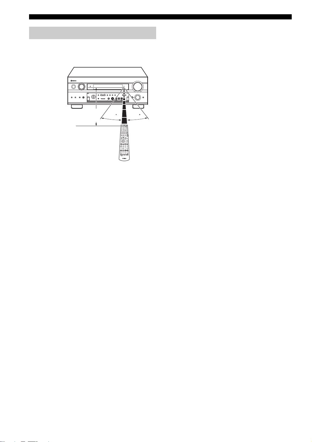
Using the remote control
The remote control transmits a directional infrared beam.
Be sure to aim the remote control directly at the remote
control sensor on the main unit during operation.
AUDIO R OPTICAL
ZONE ON/OFF
MAIN ZONE 2
VOLUME
PROGRAM
TONE CONTROL STRAIGHT
30 30
INPUT
PURE DIRECT
STANDBY
/ON
SOURCE
/REMOTE
MD/TAPEDVD
DTV
CBL/SAT
SPEAKERS
MULTI CHBINPUT MODE
A
INPUT
VCR 1
DVR
/VCR2
REC OUT/ZONE 2
Approximately 6 m (20 feet)
PRESET/
PRESET
TUNING
TUNING
/TUNING
MODE
A/B/C/D/E
FM/AM
MEMORY
CD-R
TUNER
EDIT
MAN'L/AUTO FM AUTO/MAN'L MONO
CD
S VIDEO VIDEO L
SILENT CINEMA
YPAO
OPTIMIZER
PHONES
MIC
VIDEO AUX
■ Handling the remote control
• Do not spill water or other liquids on the remote
control.
• Do not drop the remote control.
• Do not leave or store the remote control in the
following types of conditions:
– high humidity such as near a bath
– high temperature such as near a heater or stove
– extremely low temperature
– dusty places
EFFECT
8
Page 11
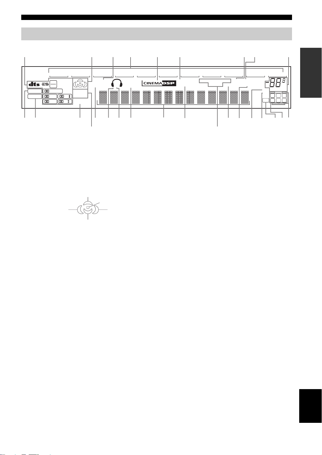
Front panel display
CONTROLS AND FUNCTIONS
135678
V–AUX
96
MATRIX
24
DISCRETE
THX
PCM
DIGITAL
PL
EX
PL
PL x
AFGHK
1 Decoder indicators
When any of this unit’s decoders function, the respective
indicator lights up.
2 Sound field indicators
Light to indicate the active DSP sound fields.
Presence DSP sound field
Left surround
DSP sound field
Surround/surround back DSP sound field
2
DVR/VCR2
ZONE2
ZONE3
ZONE4
SLEEP
BE
VCR 1
NIGHT
VIRTUAL
C
DIJ
PQ
(U.S.A., Canada, U.K., Europe and
Australia models only)
CBL/SAT
SP
A B
4
SILENT
CINEMA
DTV DVD
MD/TAPE
YPAO
HiFi DSP
CD–R CD TUNER
STEREO
EON
PS PTY RT CT
PTY HOLD
AUTO
TUNED
MEMORY
(U.K. and Europe models only)
MUTE
96/24
ft
mS
LFE
dB
LM
PHONO
VOLUME
LL C R
SL SB SR
NO0
dB
A PCM indicator
Lights up when this unit is reproducing PCM (pulse code
modulation) digital audio signals.
B SLEEP indicator
Lights up while the sleep timer is on.
C VIRTUAL indicator
Listening position
Right surround
DSP sound field
Lights up when Virtual CINEMA DSP is active (see
page 38).
D Headphones indicator
9
INTRODUCTION
Lights up when headphones are connected.
3 NIGHT indicator
Lights up when you select night listening mode.
4 Input source indicators
A cursor lights to show the current input source.
5 CINEMA DSP indicator
Lights up when you select a CINEMA DSP sound field
program.
6 YPAO indicator
Lights up during the auto setup procedure and when the
auto setup speaker settings are used without any
modifications.
7 AUTO indicator
Lights up when this unit is in the automatic tuning mode.
8 STEREO indicator
Lights up when this unit is receiving a stereo signal for an
FM stereo broadcast while the AUTO indicator is lit.
9 VOLUME level indicator
Indicates the volume level.
0 THX indicator
Lights up when a THX program is selected.
E SP A B indicators
Light up according to the set of front speakers selected.
Both indicators light up when both sets of speakers are
selected, or when bi-wiring.
F SILENT CINEMA indicator
Lights up when headphones are connected and a sound
field program is selected (see page 34).
G Multi-information display
Shows the current sound field program name and other
information when adjusting or changing settings.
H HiFi DSP indicator
Lights up when you select a HiFi DSP sound field
program.
I MEMORY indicator
Blinks to show a station can be stored.
J TUNED indicator
Lights up when this unit is tuned into a station.
K MUTE indicator
Blinks while the MUTE function is on.
English
9
Page 12

CONTROLS AND FUNCTIONS
L 96/24 indicator
Lights up when a DTS 96/24 signal is input to this unit.
M LFE indicator
Lights up when the input signal contains an LFE signal.
N Input channel indicators
Indicate the channel components of current digital input
signal.
O Presence and surround back speaker
indicators
Indicate the connection of presence and/or surround back
speakers when using the Auto Setup setting (page 26) or
Speaker Level setting (page 64).
P ZONE 2/ZONE 3 indicators
(U.S.A., Canada, U.K., Europe and Australia
models only)
Light up when Zone 2 or Zone 3 power is on.
Q RDS indicators
(U.K. and Europe models only)
The name(s) of the RDS data offered by the currently
received RDS station light(s) up.
EON lights up when an RDS station that offers the EON
data service is being received.
PTY HOLD lights up while searching for stations in the
PTY SEEK mode.
10
Page 13
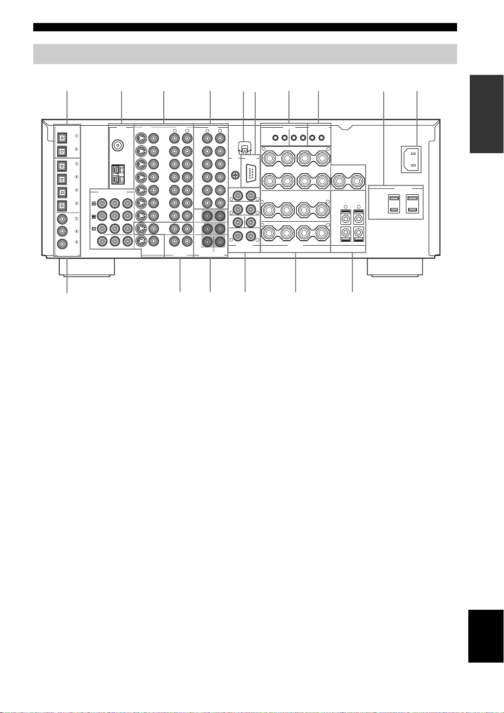
Rear panel
CONTROLS AND FUNCTIONS
1234678 9
DIGITAL OUTPUT
OPTICAL
MD/TAPE
CD-R
CD
DVD
DTV
CBL/SAT
CD
DVD
DVR/
VCR 2
COAXIAL
DIGITAL INPUT
COMPONENT VIDEO
DVD
DTVDTV
CBL/
SAT
MONITOR
OUT
TUNER
S VIDEO
FM ANT
75Ω
UNBAL.
GND
AM
ANT
P
R
PB Y
MONITOR
VIDEO
DVD
DTV
CBL/
SAT
VCR 1
OUT
DVR/VCR 2
OUT
ZONE 2
AUDIOVIDEO
R
IN
IN
ZONE 3
L
IN
(
PLAY
MD/TAPE
OUT
(
REC
IN
(
PLAY
CD-R
OUT
(
REC
CD
PHONO
FRONT (6 ch)/ SB (8 ch)
SURROUND
AUDIO
R
)
)
)
)
MULTI CH INPUTOUTPUT
A
1 DIGITAL OUTPUT jacks
See page 21 for details.
2 Antenna terminals
See page 23 for connection information.
3 Video component jacks
See pages 18 and 20 for connection information.
4 Audio component jacks
See page 21 for connection information.
5 Speaker terminal wrench hook
Use to store the speaker terminal wrench when not in use.
6 RS-232C terminal
(U.S.A., Canada, U.K., Europe and Australia
models only)
This is a control expansion terminal for commercial use.
Consult you dealer for details.
7 REMOTE 1/2 IN/OUT jacks
(U.S.A., Canada, U.K., Europe and Australia
models only)
See page 81 for details.
8 CONTROL OUT jacks
(U.S.A., Canada, U.K., Europe and Australia
L
CENTERSUB WOOFER
5
REMOTE
CONTROL OUT
2
GND
RS-232C
FRONT
R
SURROUND
R
SUB WOOFER
CENTER
R
SURROUND BACK /PRESENCE
PRE OUT
SINGLE
(SB)
R
FRONT
L
R
L
R
L
1
OUT
IN IN OUT
+
–
+
–
+
+
–
SURROUND BACK SINGLE
SURROUND
SPEAKERS
21
+12V 15mA MAX.
+
–
A
B
L
L
L
–
R
–
PRESENCE/ZONE 2
CENTER
+
L
+
–
++––
+
–
FEDCB
0 AC INLET
Use this inlet to plug in the supplied power cable (see
page 24).
A DIGITAL INPUT jacks
See pages 18, 20 and 21 for details.
B ZONE 2/ZONE 3 OUTPUT jacks
(U.S.A., Canada, U.K., Europe and Australia
models only)
See page 81 for details.
C MULTI CH INPUT jacks
See page 19 for connection information.
D PRE OUT jacks
See page 22 for connection information.
E Speaker terminals
See page 13 for connection information.
F PRESENCE/ZONE 2 speaker terminals
(U.S.A., Canada, U.K., Europe and Australia
models only)
PRESENCE speaker terminals
(other models)
See page 13 for connection information.
models only)
These are control expansion terminals for commercial use.
9 AC OUTLET(S)
Use to supply power to your other A/V components (see
page 24).
0
INTRODUCTION
AC IN
AC OUTLETS
(U.S.A. model)
English
11
Page 14
SPEAKER SETUP
+
SPEAKER SETUP
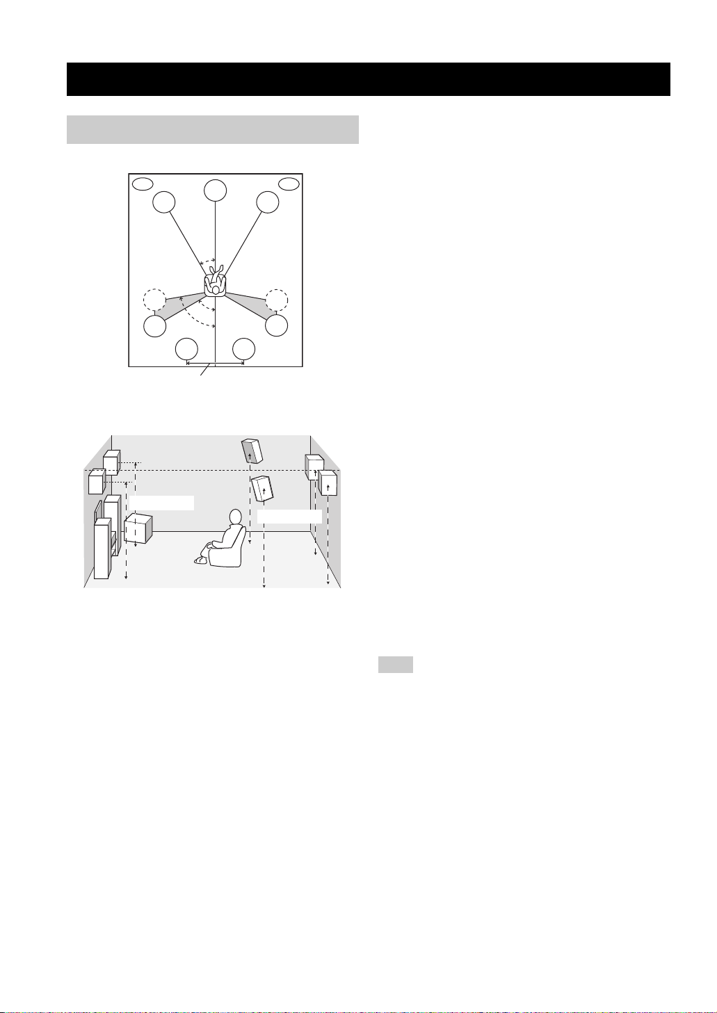
Speaker placement
For best results, place the speakers as illustrated below.
PL
FL
SL
SL
More than 30 cm (12 in)
.
1.8 m (6 ft)
80˚
SBL
C
30˚
60˚
SBR
y
The illustrations show the standard speaker setting recommended
by the ITU-R (see page 102). You can use it to enjoy CINEMA
DSP, multi-channel audio sources, and THX.
Front speakers (FR and FL)
The front speakers are used for the main source sound plus
effect sounds. Place these speakers an equal distance from
the ideal listening position. The distance of each speaker
from each side of the video monitor should be the same.
PR
FR
SR
SR
1.8 m (6 ft)
Surround speakers (SR and SL)
The surround speakers are used for effect and surround
sounds. Place these speakers behind your listening
position, facing slightly inwards, about 1.8 m (6 ft) above
the floor.
Surround back speakers (SBR and SBL)
The surround back speakers supplement the surround
speakers and provide for more realistic front-to-back
transitions. Place these speakers directly behind the
listening position and at the same height as the surround
speakers. They should be positioned at least 30 cm (12 in)
apart. Ideally, they should be positioned at the same width
as the front speakers.
Subwoofer
The use of a subwoofer, such as the YAMAHA Active
Servo Processing Subwoofer System, is effective not only
for reinforcing bass frequencies from any or all channels,
but also for high fidelity reproduction of the LFE (lowfrequency effect) channel included in Dolby Digital and
DTS software. The position of the subwoofer is not so
critical, because low bass sounds are not highly
directional. But it is better to place the subwoofer near the
front speakers. Turn it slightly toward the center of the
room to reduce wall reflections.
Presence speakers (PR and PL)
Presence speakers supplement the sound from the front
speakers with extra ambient effects produced by CINEMA
DSP (see page 48). These effects include sounds that
filmmakers intend to locate a little farther back behind the
screen in order to create more theater-like ambience. Place
these speakers at the front of the room about 0.5 - 1 m
(1 - 3 ft) outside the front speakers, facing slightly
inwards, and about 1.8 m (6 ft) above the floor.
Note
Surround back and presence speakers do not output sound
simultaneously. You can set to prioritize either set of speakers in
the Sound menu (see page 60).
Center speaker (C)
The center speaker is for the center channel sounds
(dialog, vocals, etc.). If for some reason it is not practical
to use a center speaker, you can do without it. Best results,
however, are obtained with the full system. Align the front
face of the center speaker with the front face of your video
monitor. Place the speaker centrally between the front
speakers and as close to the monitor as possible, such as
directly over or under it.
12
Page 15
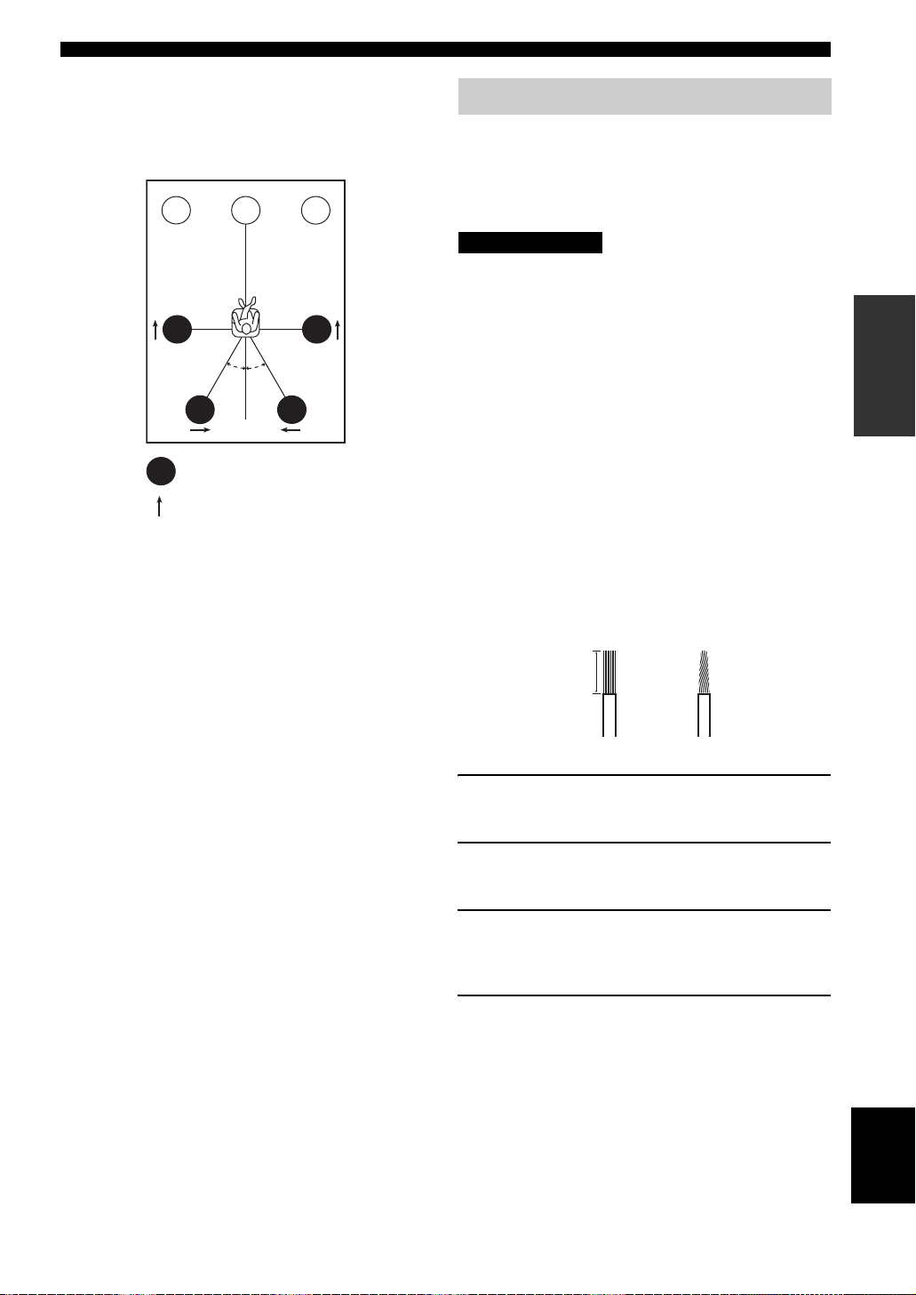
■ Di-pole speaker layout
Either di-pole or direct radiating speaker types can be used
for THX surround. If you choose di-pole speakers, please
place the surround and surround back speakers according
to the speaker layout below.
FL
SL
: Di-pole speaker
: Direction of di-pole speaker
C
30˚ 30˚
SBL
FR
SR
SBR
SPEAKER SETUP
Speaker connections
Be sure to connect the left channel (L), right channel (R),
“+” (red) and “–” (black) properly. If the connections are
faulty, no sound will be heard from the speakers, and if the
polarity of the speaker connections is incorrect, the sound
will be unnatural and lack bass.
CAUTION
• If you will use 6 ohm speakers, be sure to set
this unit’s speaker impedance setting to
6 ohms before using (see page 25). If you will
use 8 ohm speakers, use this unit’s initial
setting for speaker impedance.
• Before connecting the speakers, make sure that this
unit is disconnected from the power source.
• Do not let the bare speaker wires touch each other or do
not let them touch any metal part of this unit. This
could damage this unit and/or speakers.
• Use magnetically shielded speakers. If this type of
speaker still creates interference with the monitor,
place the speakers away from the monitor.
A speaker cord is actually a pair of insulated cables
running side by side. One cable is colored or shaped
differently, perhaps with a stripe, groove or ridges.
Connect the striped (grooved, etc.) cable to the “+” (red)
terminals on this unit and your speaker. Connect the plain
cable to the “–” (black) terminals.
PREPARATION
10 mm (3/8 in)
1
2
1 Remove approximately 10 mm (3/8 in) of
insulation from each of the speaker cables.
2 Twist the exposed wires of the cable together
to prevent short circuits.
3 Loosen the knob.
The supplied speaker terminal wrench is useful for
loosening or tightening knobs.
4 Insert one bare wire into the hole in the side
of each terminal.
English
13
Page 16
SPEAKER SETUP
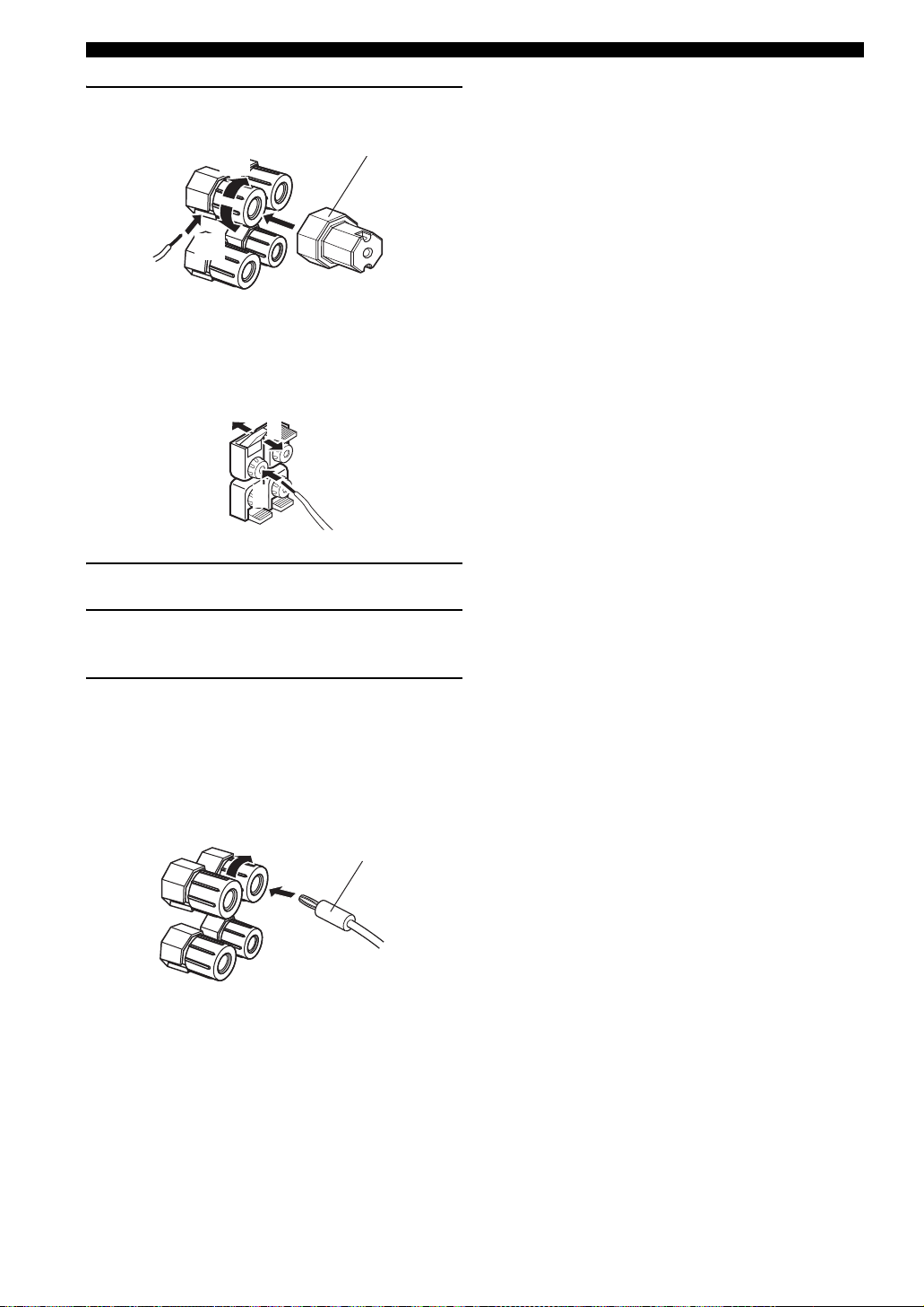
5 Tighten the knob to secure the wire.
Speaker terminal wrench
5
4
3
Red: positive (+)
Black: negative (–)
■ Connecting to PRESENCE/ZONE 2 or
PRESENCE speaker terminals
1
3
2
1 Open the tab.
2 Insert one bare wire into the hole of each
terminal.
3 Return the tab to secure the wire.
■ Banana plug connections
(With the exception of U.K., Europe and Asia models)
First, tighten the knob and then insert the banana plug
connector into the end of the corresponding terminal.
Banana plug
(With the exception of U.K., Europe
and Asia models)
y
You can also use banana plugs with the PRESENCE/ZONE 2 and
PRESENCE speaker terminals. Open the tab, then insert one
banana plug connector into the hole of each terminal. Do not
attempt to close the tabs after connecting the banana plugs.
14
Page 17
10
SPEAKER SETUP
9
2
4
3
1
7
8
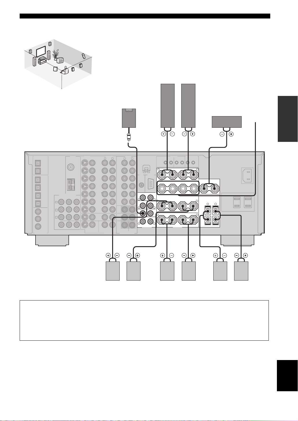
Speaker layout
5
6
Front speakers (A)
LeftRight
Subwoofer with
built-in amplifier
Center
speaker
Front
speakers
PREPARATION
(B)
FRONT
R
SURROUND
R
SUB WOOFER
R
SURROUND BACK /PRESENCE
PRE OUT
CENTER
SINGLE
(SB)
231
+
+
R
FRONT
+
L
+
R
L
+
R
L
–
–
A
–
–
B
SURROUND
–
–
SURROUND BACK SINGLE
SPEAKERS
L
L
L
–
R
–
PRESENCE/ZONE 2
CENTER
+
L
+
++––
+
4
(U.S.A. model)
7 8 65 109
Surround speakers
LeftRight LeftRight
Surround back speakers
Presence speakers
LeftRight
• You can connect both surround back and presence speakers to this unit, but they do not output sound simultaneously.You can set
to prioritize either set of speakers in the Sound menu (see page 60).
• The surround back speakers output the surround back channel included in Dolby Digital EX and DTS-ES software and only
operate when the Dolby Digital EX, DTS-ES or Dolby Pro Logic IIx decoder is turned on.
• The presence speakers output ambient effects created by the DSP sound fields. They do not output sound when other sound fields
are selected.
English
15
Page 18
SPEAKER SETUP
■ FRONT terminals
Connect one or two speaker systems to these terminals. If
you use only one speaker system, connect it to either of
the FRONT A or B terminals.
Note
The Canada model cannot output to two separate speaker systems
simultaneously.
Bi-wired connection
The unit also allows you to make bi-wired connections to
one speaker system. Use two pairs of speaker cables for
each speaker (one pair for the woofer and one pair for the
tweeter/mid-range). To use the bi-wired connections, press
SPEAKERS A and SPEAKERS B on the front panel so
that both SP A and B light up on the front panel display.
Bi-wired connection
+
–
A
–
B
L
+
–
FRONT
++–
R
■ CENTER terminals
Connect a center speaker to these terminals.
■ SURROUND terminals
Connect surround speakers to these terminals.
■ SUBWOOFER jack
Connect a subwoofer with a built-in amplifier, such as the
YAMAHA Active Servo Processing Subwoofer System,
to this jack.
■ SURROUND BACK terminals
Connect surround back speakers to these terminals. If you
only connect one surround back speaker, connect it to the
left (L) terminals.
■ PRESENCE terminals
Connect presence speakers to these terminals.
Note
(U.S.A., Canada, U.K., Europe and Australia models only)
You can also use these terminals to connect Zone 2 speakers (see
page 66).
This unit
16
Page 19
CONNECTIONS
Before connecting components
CAUTION
Do not connect this unit or other components to the mains
power until all connections between components are
complete.
■ Cable indications
For analog signals
left analog cables
right analog cables
L
R
CONNECTIONS
■ Video jacks
This unit has three types of video jacks. Connection
depends on the availability of input jacks on your monitor.
The signals input through the S VIDEO jacks on this unit
are automatically converted for output through the VIDEO
jacks. When “Video Conv.” is set to “On” (see page 65),
signals input through the VIDEO jacks can be output
through the S VIDEO and COMPONENT VIDEO jacks.
Likewise, signals input through the S VIDEO jacks can
also be output through the COMPONENT VIDEO jacks.
VIDEO
S VIDEO
COMPONENT VIDEO
PR PB Y
PREPARATION
For digital signals
optical cables
coaxial cables
For video signals
video cables
S-video cables
O
C
V
S
V
■ Analog jacks
You can input analog signals from audio components by
connecting audio pin cables to the analog jacks on this
unit. Connect red plugs to the right jacks and white plugs
to the left jacks.
■ Digital jacks
This unit has digital jacks for direct transmission of digital
signals through either coaxial or fiber optic cables. You
can use the digital jacks to input PCM, Dolby Digital and
DTS bitstreams. When you connect components to both
the COAXIAL and OPTICAL jacks, priority is given to
the input signals from the COAXIAL jack. All digital
input jacks are compatible with 96-kHz sampling digital
signals.
Note
This unit handles digital and analog signals independently. Thus
audio signals input to the analog jacks are only output to the
analog OUT (REC) jacks. Likewise audio signals input to the
digital (OPTICAL or COAXIAL) jacks are only output to the
DIGITAL OUTPUT jacks.
VIDEO jack
For conventional composite video signals.
S VIDEO jack
For S-video signals, separated into luminance (Y) and
color (C) video signals to achieve high-quality color
reproduction.
COMPONENT VIDEO jacks
For component signals, separated into luminance (Y) and
color difference (PB, PR) to provide the best quality in
picture reproduction.
Signal flow inside this unit
Input
COMPONENT
VIDEO
S VIDEO
VIDEO
Only when “Video Conv.” is set to “On”
(see page 65)
Output
(MONITOR OUT)
Note
When signals are input through both the S VIDEO and VIDEO
jacks, signals input through the S VIDEO jack have priority.
17
English
Page 20
CONNECTIONS
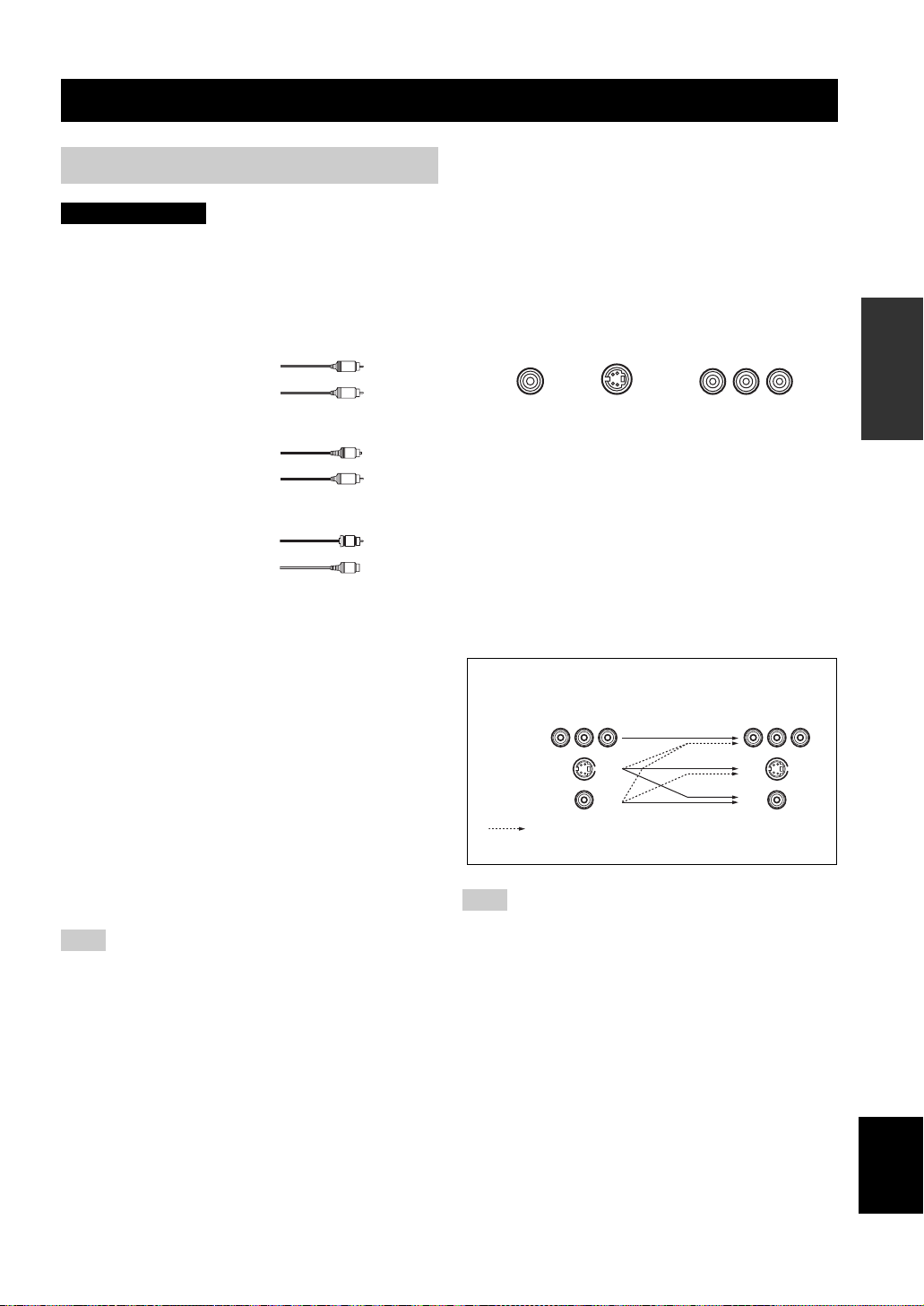
Connecting video components
■ Connections for DVD playback
Coaxial out
Optical out Video out
C
O
DVD player
Audio out
S VIDEO
VIDEO
DVD
LR
AUDIOVIDEO
R
L
Video
monitor
DVD
Video in
COMPONENT VIDEO
Y
DVD
P
R
P
B
DVD
(U.S.A. model)
MONITOR
OUT
MONITOR
18
Page 21
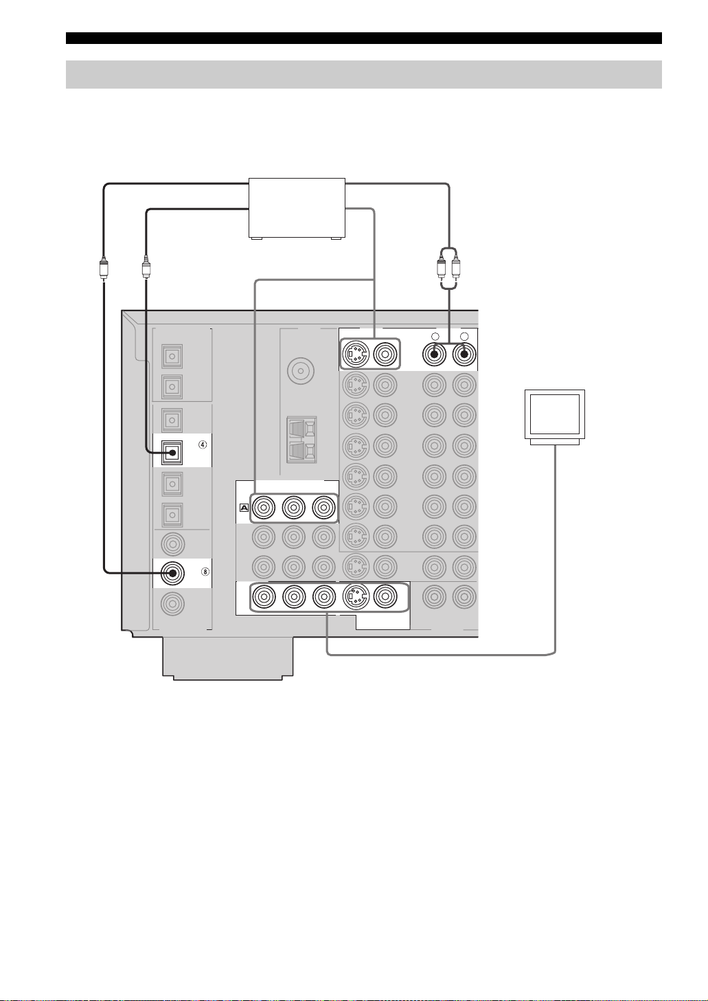
CONNECTIONS
■ Connecting to the MULTI CH INPUT jacks
This unit is equipped with 6 additional input jacks (left and right FRONT, CENTER, left and right SURROUND and
SUBWOOFER) for discrete multi-channel input from a multi-format player, external decoder, sound processor or preamplifier.
If you set Multi CH Assign: Input Channels to 8ch (see page 57), you can use input jacks assigned as Multi CH Assign:
Front Input (page 57) together with the MULTI CH INPUT jacks to input 8 channels.
Connect the output jacks on your multi-format player or external decoder to the MULTI CH INPUT jacks. Be sure to
match the left and right outputs to the left and right input jacks for the front and surround channels.
For 6-channel input For 8-channel input
FRONT(6CH)/SB(8CH)
SURROUND
SUB WOOFER
MULTI CH INPUT
Subwoofer
LR
out
Multi-format player/
External decoder
Front
out
CENTER
Center
out
LR
Surround
out
Surround
back out
FRONT(6CH)/SB(8CH)
SURROUND
CENTER
SUB WOOFER
MULTI CH INPUT
Subwoofer
out
Center
out
Multi-format player/
External decoder
LRLR
Surround out
R
L
Front out
DVD
DTV
CBL
/SAT
VCR 1
DVR/
VCR 2
R
L
IN
IN
IN
(
PLAY
MD/TAPE
OUT
(
REC
IN
(
PLAY
CD-R
CD
AUDIOAU DIO
R
L
)
)
)
Notes
• When you select MULTI CH INPUT as the input source, this unit automatically turns off the digital sound field processor, and you
cannot select sound field programs.
• This unit does not redirect signals input to the MULTI CH INPUT jacks to accommodate for missing speakers. We recommend that
you connect at least a 5.1-channel speaker system before using this feature.
• When headphones are used, only front L/R channels are output.
PREPARATION
19
English
Page 22
CONNECTIONS
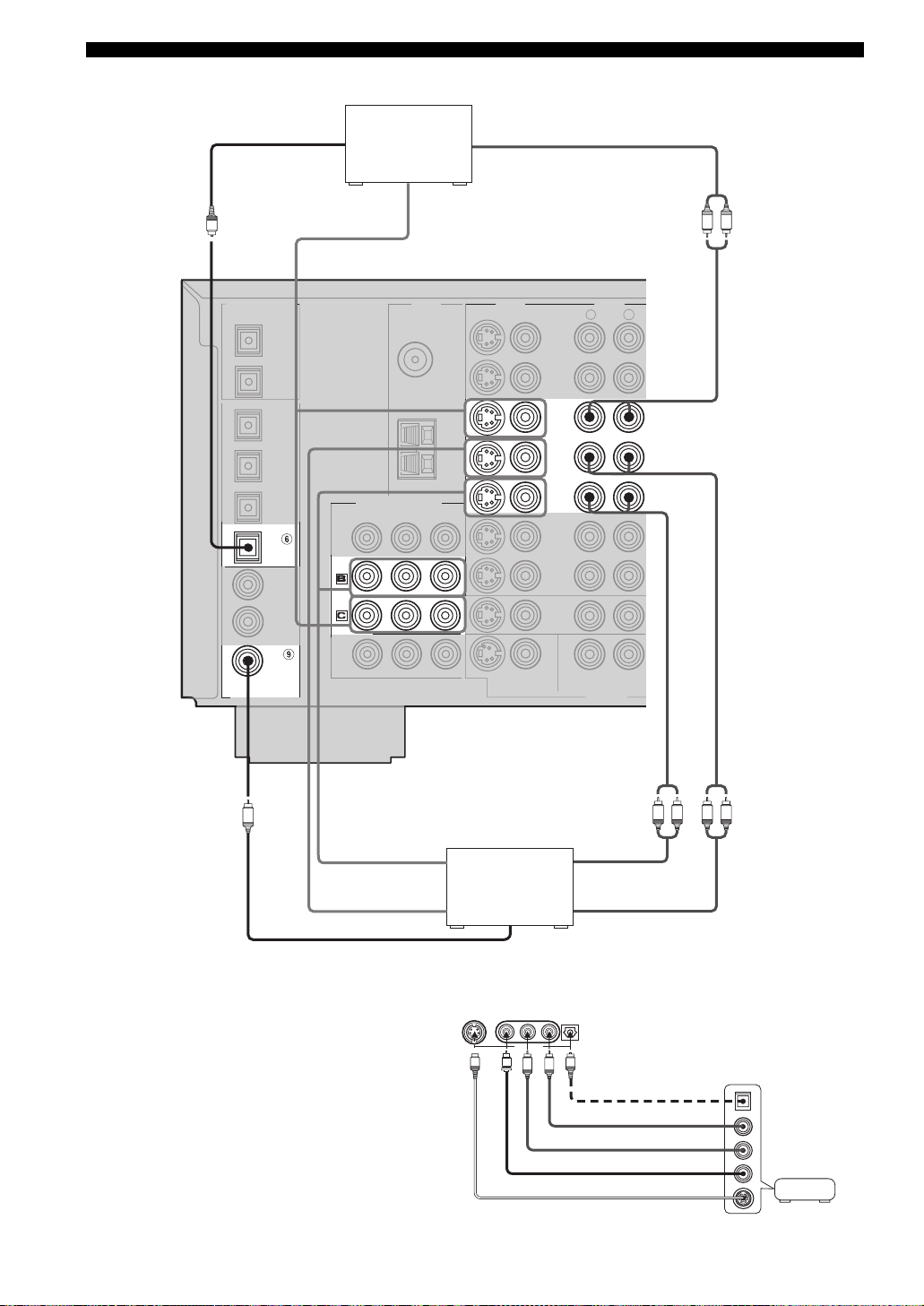
■ Connections for other video components
Optical out
Cable TV or
Audio out
satellite tuner
Video out
O
AUDI OVIDEO
CBL/
SAT
IN
VCR 1
OUT
CBL/SAT
COMPONENT VIDEO
DTVDTV
CBL/
SAT
LR
DVR/
VCR 2
COAXIAL
DIGITAL INPUT
C
Video in
Video out
Coaxial out
■ VIDEO AUX jacks (on the front panel)
Use these jacks to connect any video source, such as a
game console or camcorder, to this unit.
DVD recorder
or VCR
S VIDEO VIDEO
L AUDIO R OPTICAL
VIDEO AUX
V
S
L
(U.S.A. model)
Audio in
Audio out
O
R
Optical out
Audio out R
Audio out L
Video out
S-video out
LR LR
Game
console or
video camera
20
Page 23
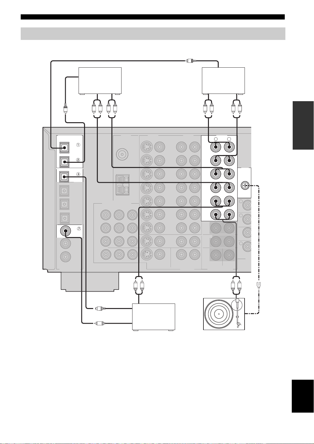
Connecting audio components
■ Connections for audio components
Optical in
CD recorder
CONNECTIONS
O
Optical in
MD recorder or
tape deck
Audio in Audio out
O
DIGITAL OUTPUT
OPTICAL
MD/TAP E
CD-R
CD
CD
DIGITAL INPUT
LRLRLR LR
IN
(
)
PLAY
MD/TAPE
OUT
(
)
REC
IN
(
)
PLAY
CD-R
OUT
(
)
REC
CD
PHONO
R
AUDI O
Audio inAudio out
PREPARATION
L
GND
(U.S.A. model)
O
Coaxial out
C
Optical out
Audio out
CD player
■ Connecting a turntable
PHONO jacks are for connecting a turntable with an MM
or high-output MC cartridge. If you have a turntable with
a low-output MC cartridge, use an in-line boosting
transformer or MC-head amplifier when connecting to
these jacks.
LRLR
Audio out
GND
Turn ta bl e
y
Connect your turntable to the GND terminal to reduce noise in
the signal. However you may hear less noise without the
connection to the GND terminal for some record players.
English
21
Page 24
CONNECTIONS
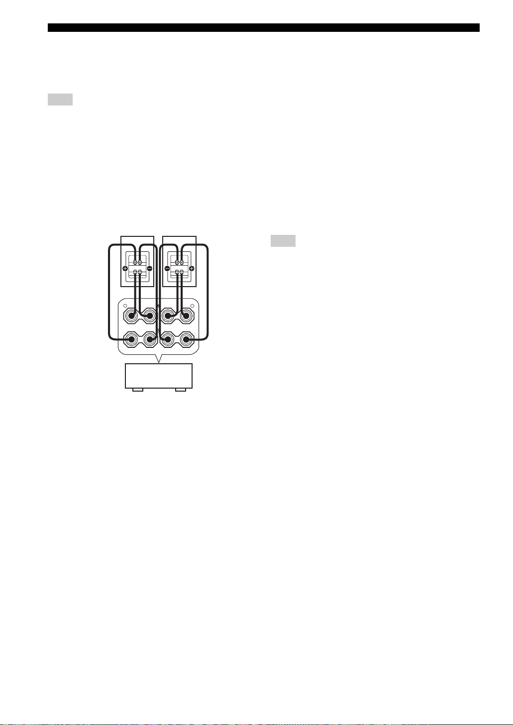
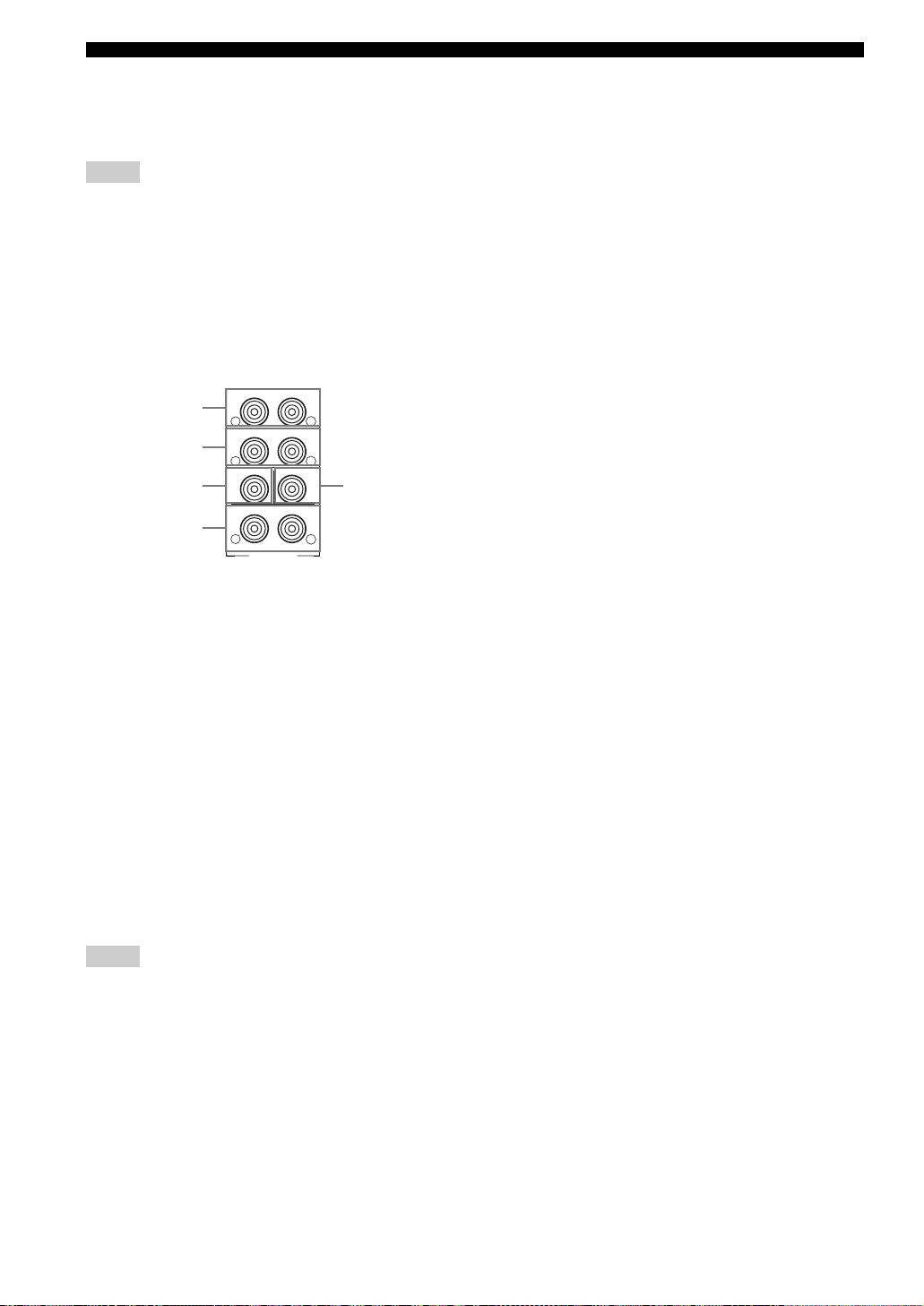
■ Connecting to an external amplifier
If you want to increase the power output to the speakers,
or want to use another amplifier, connect an external
amplifier to the PRE OUT jacks as follows.
Notes
• When audio pin plugs are connected to the PRE OUT jacks for
output to an external amplifier, it is not necessary to use the
corresponding SPEAKERS terminals. Set the volume of the
external amplifier connected to this unit to the maximum.
• The signal output through the FRONT PRE OUT and CENTER
PRE OUT jacks are affected by the TONE CONTROL settings.
• If SPEAKERS A is turned off and Multi Zone: Speaker B is set
to “Zone B” (see page 66), signals will only be output from the
FRONT PRE OUT jacks.
FRONT
1
SURROUND
2
SUB WOOFER
3
4
SURROUND BACK /PRESENCE
R
R
R
PRE OUT
CENTER
SINGLE
(SB)
L
L
5
L
1 FRONT PRE OUT jacks
Front channel line output jacks.
2 SURROUND PRE OUT jacks
Surround channel line output jacks.
3 SUBWOOFER PRE OUT jack
Connect a subwoofer with built-in amplifier, such as the
YAMAHA Active Servo Processing Subwoofer System,
to this jack.
4 SURROUND BACK/PRESENCE PRE OUT
jacks
Surround back or presence channel line output jacks. If
you only connect one external amplifier for the surround
back channel, connect it to the left (L) jack.
5 CENTER PRE OUT jack
Center channel line output jack.
Notes
• Each PRE OUT jack outputs the same channel signal as the
corresponding speaker terminals. However, when both surround
back and presence speakers are setup in this unit, the signals
output from SURROUND BACK/PRESENCE PRE OUT jacks
may not correspond to the correct speakers.
• Adjust the volume level of the subwoofer with the control on
the subwoofer.
• Some signals may not be output from the SUBWOOFER PRE
OUT jack depending on the Speaker Set settings (see page 61).
22
Page 25
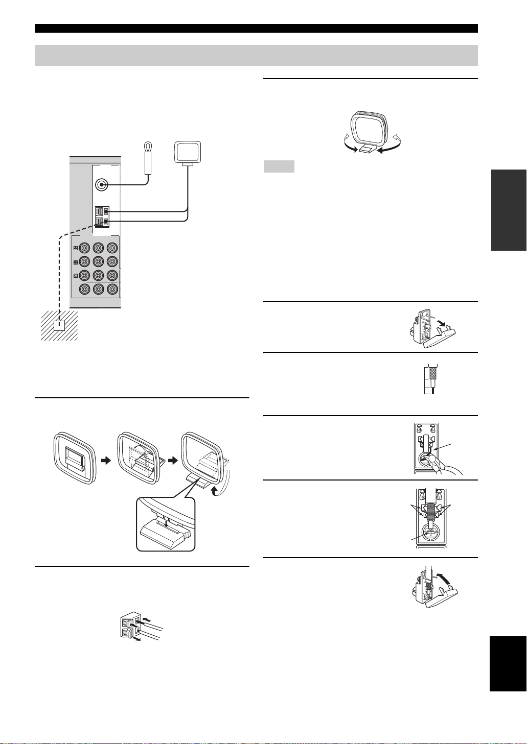
Connecting the antennas
Both AM and FM indoor antennas are included with this
unit. In general, these antennas should provide sufficient
signal strength. Connect each antenna correctly to the
designated terminals.
CONNECTIONS
3 Orient the AM loop antenna for the best
reception.
Indoor FM antenna
(included)
TUNER
FM ANT
75Ω
UNBAL.
GND
AM
ANT
COMPONENT VIDEO
P
R
PB Y
DVD
DTVDTV
CBL/
SAT
MONITOR
OUT
Ground (GND terminal)
For maximum safety and minimum interference,
connect the antenna
ground. A good earth ground is a metal stake driven
into moist earth.
GND terminal to a good earth
AM loop antenna
(included)
■ Connecting the AM loop antenna
1 Set up the AM loop antenna, then connect it
to the terminals on this unit.
Notes
• The AM loop antenna should be placed away from this unit.
• The AM loop antenna should always be connected, even if an
outdoor AM antenna is connected to this unit.
• A property installed outdoor antenna provides clearer reception
than an indoor one. If you experience poor reception quality, an
outdoor antenna may improve the quality. Consult the nearest
authorized YAMAHA dealer or service center about outdoor
antennas.
■ 75-ohm/300-ohm antenna adapter
(U.K. model only)
1 Open the cover of the
included 75-ohm/300-ohm
antenna adapter.
2 Cut the external sleeve
of the 75-ohm coaxial
cable and prepare it for
11 (7/16)
8 (5/16)
6 (1/14)
Unit:
mm (in)
connection.
3 Cut the lead wire and
remove it.
Lead wire
PREPARATION
2 Press and hold the tab to insert the AM loop
antenna lead wires into the AM ANT and GND
terminals.
4 Insert the cable
wire into the slot,
and clamp it with
pliers.
Insert the wire
into the slot
5 Snap the cover into place.
Clamp
Clamp
English
23
Page 26
CONNECTIONS
Connecting the power cable
AC OUTLETS
(U.S.A. model)
VOLTAGE SELECTOR
E
G
TA
L
VO
R
CTO
2
SELE
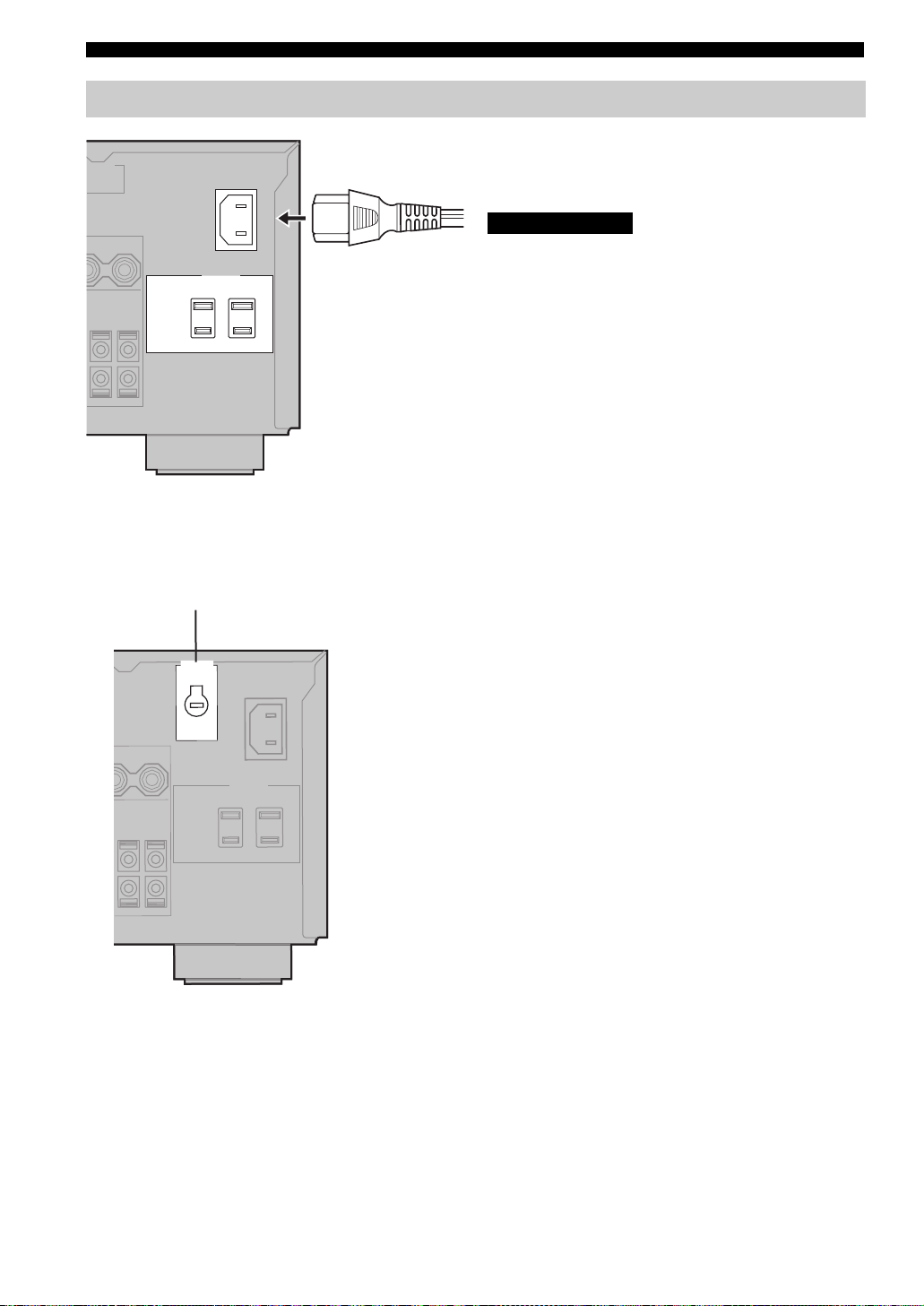
■ Connecting the AC power cable
Plug the power cable into the AC inlet after all other
connections are complete, then plug the power cable to an
AC wall outlet.
CAUTION
Do not use other AC power cables. Use the one provided.
Use of other power cables may result in fire hazard or
electrical shock.
■ AC OUTLET(S) (SWITCHED)
U.K. and Australia models..................................... 1 outlet
Korea model............................................................... None
Other models......................................................... 2 outlets
Use these outlets to connect the power cables from your
other components to this unit. Power to the AC
OUTLET(S) is controlled by this unit’s STANDBY/ON
(or SYSTEM POWER and STANDBY). These outlets
will supply power to any connected component whenever
this unit is turned on. The maximum power (total power
consumption of components) that can be connected to the
AC OUTLET(S) is:
Asia and General models .......................................... 50 W
Other models ........................................................... 100 W
■ VOLTAGE SELECTOR
(Asia and General models only)
The VOLTAGE SELECTOR on the rear panel of this unit
must be set for your local main voltage BEFORE plugging
into the AC main supply. Voltages are:
General model....... AC 110/120/220/230–240 V, 50/60 Hz
Asia model........................... AC 220/230–240V, 50/60 Hz
24
■ Memory back-up
The memory back-up circuit prevents the stored data from
being lost even if this unit is in the standby mode.
However if the power cable is disconnected from the AC
wall outlet, or the power supply is cut for more than one
week, the stored data will be lost.
(General model)
Page 27
CONNECTIONS
SELECT
DTV DVR/VCR2VCR 1 DVD
V-AUX
CBL/SAT MD/TAPE
CD-R
PHONO TUNER CD
MULTI CH IN
POWER POWER POWER
SYSTEM
STANDBY
AVTV
SLEEP
INPUT MODE
A
B
AMP
Speaker impedance setting
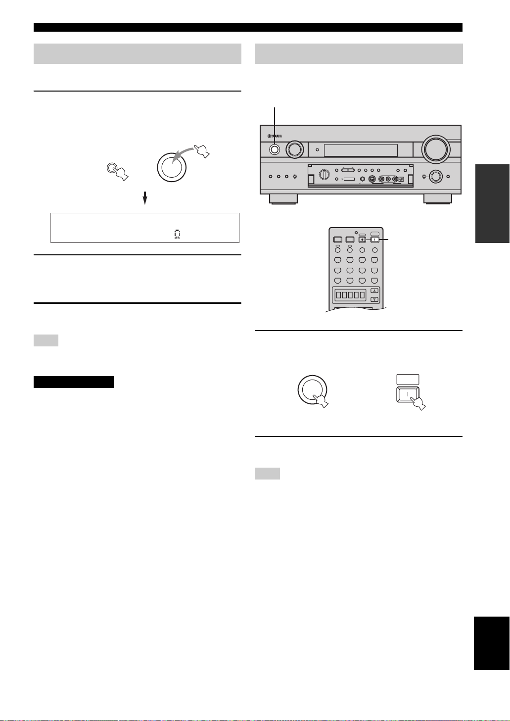
Be sure this unit is in the standby mode.
1 On the front panel, while holding down
STRAIGHT/EFFECT, press STANDBY/ON.
“SP IMP.–8ΩMIN” appears on the front panel
display.
STRAIGHT
STANDBY
/ON
EFFECT
SP IMP.-8 MIN
2 Press STRAIGHT/EFFECT to select the
impedance of your speakers.
You can select either 6 ohms or 8 ohms.
3 Press STANDBY/ON to exit the setting.
This unit will be set to the standby mode.
Note
Speaker impedance setting function is located in the Advanced
menu (see page 84).
CAUTION
If you are using 6 ohm speakers, set the impedance to
6 ohms before turning on the power.
Turning on the power
When all connections are complete, turn on the power of
this unit.
1
INPUT
PURE DIRECT
MEMORY
MAN'L/AUTO FM AUTO/MAN'L MONO
S VIDEO
TUNING
MODE
VIDEO AUDIO OPTICALLR
VIDEO AUX
ZONE ON/OFF
MAIN ZONE 2
/
SOURCE
PRESET
MULTI CH
INPUT
CBL/SAT
VCR 1
DVR
/VCR2
REC OUT /ZONE 2
/REMOTE
DVD
MD/TAPE
D–TV
INPUT MODE
PRESET
TUNING
A/B/C/D/E
/TUNING
CD–R
TUNER
CD
FM/AM
EDIT
SILENT CINEMA
YPAO
OPTIMIZER
MIC
PHONES
SPEAKERS
A B
STANDBY
/
ON
1
1 Press STANDBY/ON (SYSTEM POWER on the
remote controls) to turn on the power of this
unit.
SYSTEM
STANDBY
/ON
Front panel
or
POWER
Remote control
VOLUME
PROGRAM
TONE CONTROL
STRAIGHT
EFFECT
(U.S.A. model)
PREPARATION
2 Turn on the video monitor connected to this
unit.
Note
Press STANDBY/ON again (STANDBY on the remote control)
to enter the standby mode.
English
25
Page 28
AUTO SETUP
YPAO
AUTO SETUP
Introduction
This receiver employs YAMAHA Parametric Room
Acoustic Optimizer (YPAO) technology which lets you
avoid troublesome listening-based speaker setup and
achieves highly accurate sound adjustments. The supplied
optimizer microphone collects and analyzes the sound
your speakers produce in your actual listening
environment.
Notes
• Please be advised that it is normal for loud test tones to be
output during the auto setup procedure.
• If auto setup stops and error messages appear on the screen,
follow the troubleshooting on page 30.
YPAO performs the following checks and makes
appropriate adjustments to give you the best possible
sound from your system.
Wiring
Checks which speakers are connected and the polarity of
each speaker.
Distance
Checks the distance of each speaker from the listening
position and adjusts the timing of each channel.
Size
Checks the speaker’s frequency response and sets the
appropriate low frequency crossover for each channel.
Equalizing
Adjusts frequency and levels of each channel’s parametric
equalizer to reduce coloration across the channels and
create a cohesive sound field. This is particularly
important if you use different brands or sizes of speakers
for some channels or have a room with unique sonic
characteristics.
YPAO equalizing calibration incorporates three
parameters (frequency, level and Q factor) for each of the
seven bands in its parametric equalizer to provide highly
precise automatic adjustment of frequency characteristics.
Level
Checks and adjusts the sound level (volume) of each
speaker.
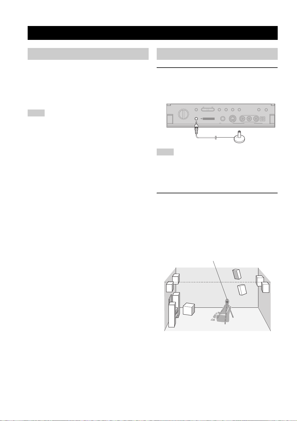
Optimizer microphone setup
1 Connect the supplied optimizer microphone
to the OPTIMIZER MIC jack on the front
panel.
(U.S.A. model)
VIDEO AUDIO OPTICALL R
VIDEO AUX
ZONE ON/OFF
MAIN ZONE 2
D–TV
CBL/SAT
VCR 1
DVR
/VCR2
REC OUT /ZONE 2
SOURCE
/REMOTE
DVD
MD/TAPE
CD–R
TUNER
CD
A/B/C/D/E
OPTIMIZER
/
PRESET
PRESET
TUNING
/TUNING
EDIT
SILENT CINEMA
YPAO
MIC
FM/AM
PHONES
TUNING
MEMORY
MODE
MAN'L/AUTO FM AUTO/MAN'L MONO
S VIDEO
Notes
• After you have completed the auto setup procedure, be sure to
disconnect the optimizer microphone.
• The optimizer microphone is sensitive to heat.
– Keep it away from direct sunlight.
– Do not place it on top of this unit.
2 Place the optimizer microphone on a flat
level surface with the omni-directional
microphone head upward, at your normal
listening position.
If possible, use a tripod (etc.) to affix the optimizer
mic at the same height as your ears would be when
you are seated in your listening position.
Optimizer microphone position
26
Page 29
AUTO SETUP
Starting the setup
For best results, make sure the room is as quiet as possible
during the auto setup procedure (YPAO). If there is too
much ambient noise, the results may not be satisfactory.
y
If your subwoofer can adjust the output volume and the crossover
frequency, set the volume to about half way (or slightly less) and
set the crossover frequency to the maximum.
VOLUME
MAX
MIN
Subwoofer
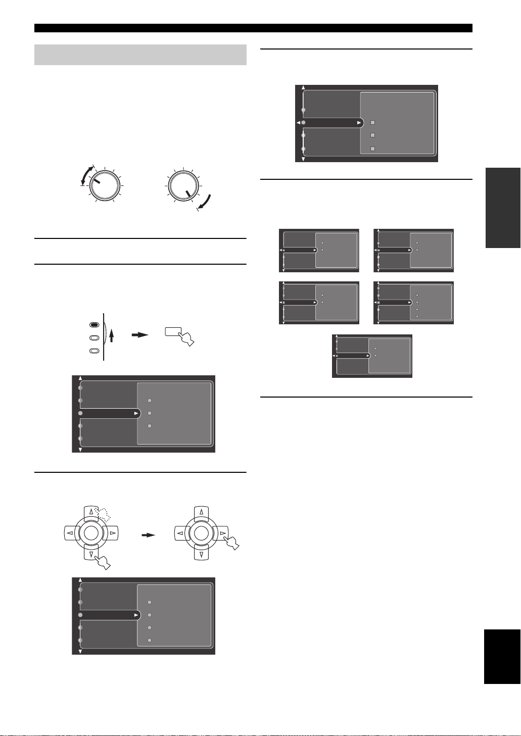
1 Switch on this unit and video monitor.
2 Set AMP/SOURCE/TV to AMP, then press
TOP on the remote control.
The top display appears.
AMP
SOURCE
TV
CROSSOVER/
HIGH CUT
MIN
TOP
TITLE
MAX
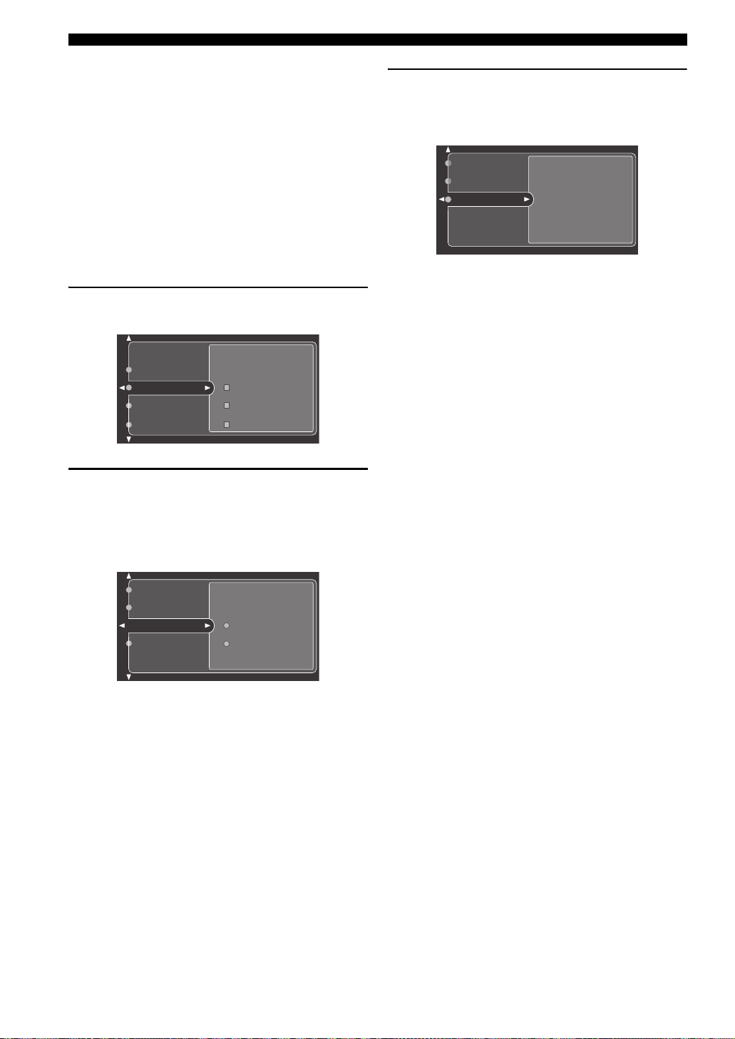
4 Press k / n repeatedly to select Setup Menu,
then press h.
Information
Setup Menu
Setup Type
Start
Wiring
Distance
Size
5 Press k / n repeatedly to select Wiring,
Distance, Size, Equalizing or Level, then
press h.
Wiring
Distance
Size
Wiring
Distance
Size
Equalizing
Level
Skip
Check
Skip
Check
Size
Equalizing
Level
Wiring
Distance
Size
Equalizing
Distance
Size
Equalizing
Level
Skip
Check
Skip
Check
Skip
Check: Natural
Check: Flat
Check: Front
PREPARATION
Stereo/Surround
Input Select
Manual Setup
Auto Setup
System Memory
Sound
Basic
Option
3 Press k / n repeatedly to select Auto Setup,
then press h.
ENTER
Input Select
Manual Setup
Auto Setup
System Memory
Audio Info.
Information
Setup Menu
Setup Type
Start
ENTER
6 For Wiring, Distance, Size or Level, select:
Check To automatically check and adjust the selected
item.
Skip To skip the selected item and perform no
adjustments.
y
When using THX speakers, select Skip for Size and make
sure that “Small” or “Small x2” is selected in Speaker Set
(page 61) and that “80Hz (THX)” is selected in Bass Cross
Over (page 63).
English
27
Page 30
AUTO SETUP
For Equalizing, press k / n to select:
Skip To skip the selected item and perform no
Check: Natural To average out the frequency response of all
Check: Flat To average the frequency response of all
Check: Front To adjust the frequency response of each
adjustments.
speakers with higher frequencies being less
emphasized. Recommended if the “Flat”
setting sounds a little harsh.
speakers. Recommended if all of your
speakers are of similar quality.
speaker in accordance with the sound of
your front speakers. Recommended if your
front speakers are of much higher quality
than your other speakers.
7 Once you have selected the desired setting,
press l to move back to Setup Menu.
Information
Setup Menu
Setup Type
Start
Wiring
Distance
Size
9 Press n to select Start, then press ENTER.
Loud test tones are output from each speaker and
“Measuring” appears during the auto setup
procedure.
Setup Menu
Setup Type
Press ENTERStart
• To stop the auto setup procedure, press one of the cursor
buttons (
k / n / l / h) or ENTER. In the pause mode,
press k to retry the procedure,
• If an error message appears during testing, refer to
“Troubleshooting for the auto setup procedure” on
page 30, and after carrying out the remedy, retry the auto
setup procedure.
l to cancel auto setup.
8 Press n to select Setup Type, then select:
Auto To automatically perform the entire
auto setup procedure.
Step To pause for confirmation between
each check in the auto setup procedure.
Information
Setup Menu
Setup Type
Start
Auto
Step
28
Page 31

Confirming the results
AUTO SETUP
If you set Setup Type to Step.
The results are displayed individually after each analysis.
You can confirm the results of each analysis.
If you set Setup Type to Auto.
The results are displayed after all items have been
analysed.
Setup Menu
Setup Type
Start
• Press n and select Setup to set the measured values.
• Press k and select Retry to retry the auto setup procedure.
• Press h and select Detail to view information about
measurement results and warning messages. For more
details about warning messages, see “Troubleshooting for
the auto setup procedure” on page 30.
• Press l and select Exit to exit from the auto setup
procedure. If you select Exit, “Don’t Setup?” appears on
the screen. To set the measured values and exit, select Yes.
To cancel the settings and exit, select No.
Retry
Exit Detail
Setup
Measurement Over
Successfully
Distance
Size
Equalizing
Level
Result
Retry
Exit Detail
Next
•Press n and select Next to start measurement of the next
menu item.
•Press k and select Retry to retry the auto setup procedure.
•Press h and select Detail to view information about
measurement results and warning messages. For more
details about warning messages, see “Troubleshooting for
the auto setup procedure” on page 30.
•Press l and select Exit to exit from the auto setup
procedure.
After all menu items have been measured, “Measurement
Over” appears on the screen and the results for each item
are displayed.
•Press n and select Setup to set the measured values.
•Press k and select Retry to retry the auto setup procedure.
•Press h and select Detail to view information about
measurement results and warning messages. For more
details about warning messages, see “Troubleshooting for
the auto setup procedure” on page 30.
•Press l and select Exit to exit from the auto setup
procedure. If you select Exit, “Don’t Setup?” appears on
the screen. To set the measured values and exit, select Yes.
To cancel the settings and exit, select No.
y
If you want to make more detailed settings, change the system
parameters using the Manual Setup menu. If you want to return to
the Auto Setup settings after making settings in the Manual Setup
menu, navigate to the Information screen in the Auto Setup menu,
press k / n repeatedly to select the parameter you want to adjust,
then press ENTER.
Notes
• If you change speakers, speaker positions, or the layout of your
listening environment, perform auto setup again to re-calibrate
your system.
• In the Distance results, the distance displayed may be longer
than the actual distance depending on the characteristics of your
subwoofer. This may also be the case when using an external
amplifier.
• In the Equalizing results, different values may be set for the
same band to provide finer adjustments.
PREPARATION
29
English
Page 32

AUTO SETUP
■ Troubleshooting for the auto setup procedure
Before auto setup
Error message Cause Remedy
Connect MIC! Optimizer microphone is not connected. • Connect the supplied optimizer microphone to the
Unplug Phones! Headphones are connected. • Unplug the headphones.
No Setup Menu! No setup menu items have been selected. • Select at least one setup menu item.
Memory Guard! This setting is protected. • Remove the protection setting for auto setup (see
During auto setup
Press l / h to display detailed information for individual errors. Select Retry to try the auto setup procedure again.
Error message Cause Remedy
E01:No Front SP Front L/R channel signal(s) is (are) not
detected.
E02:No Surr. SP Only one surround channel signal is detected. • Check the surround speaker connections.
E03:No Pres. SP Only one presence channel signal is detected. • Check the presence speaker connections.
E04:SBR ->SBL Only the surround back right channel signal is
detected.
E05:Noisy Background noise is too loud. • Try auto setup in a quiet environment.
E06:Check Surr. Surround back speaker(s) is (are) connected,
though surround L/R speakers are not.
E07:No MIC The optimizer microphone was unplugged
during the auto setup procedure.
E08:No Signal The optimizer microphone does not detect test
tones.
E09:User Cancel The auto setup procedure was cancelled
because a setting that affects auto setup was
changed during the procedure.
E10:Internal Err An internal error occurred. • Restart this unit, then try the auto setup procedure
OPTIMIZER MIC jack on the front panel.
page 67).
• Select the front speakers with SPEAKERS A or B.
• Check the front L/R speaker connections.
• Connect the surround back speaker to the LEFT
SURROUND BACK SPEAKERS terminal if you
only have one surround back speaker.
• Turn off noisy electric equipment like air
conditioners, or move them away from this unit.
• Connect surround speakers when using (a) surround
back speaker(s).
• Connect the supplied optimizer microphone to the
OPTIMIZER MIC jack on the front panel.
• Check the microphone setting.
• Check the speaker connections and placement.
• Perform the auto setup procedure again.
again.
30
Page 33

AUTO SETUP
After auto setup
The following warning messages are displayed after analysis is complete to inform you of possible problems. We
recommend that you check the contents of each message, then select Retry to try the auto setup procedure again.
Warning message Cause Remedy
W1:Out of Phase Speaker polarity is incorrect. This message may
appear depending on the speakers even when
they are connected correctly.
W2:Over Distance The distance between the speaker and the
listening position is over 24 m (80 ft).
W3:Level Error The difference in volume level between the
speakers is excessive. (No level correction is
made.)
W4:SP Mismatch The speaker settings differ from the
measurement results of wiring (only occurs
when the wiring measurement procedure is
skipped).
• Check the speaker connections.
• Bring the speaker closer to the listening position.
• Readjust the speaker installation.
• Check the speaker connections.
• Use speakers of similar quality.
• Adjust the output volume of the subwoofer.
• Check the speaker connections.
PREPARATION
31
English
Page 34

PLAYBACK
MENU
PURE DIRECT
TITLE
A/B/C/D/E
SELECT
DTV DVR/VCR2VCR 1 DVD
V-AUX
CBL/SAT MD/TAPE CD-R
PHONO TUNER CD
MULTI CH IN
VOL
+
–
POWER POWER POWER
SYSTEM
STANDBY
AVTV
SLEEP
INPUT MODE
A
B
CH
+
–
TV VOL
TV MUTE TV INPUT
MUTE
+
–
AMP
SOURCE
TV
EXIT
TOP
CLEAR
LEARN
RE–NAME
MENU
FREQ/RDS EON MODE PTY SEEK START
REC
DISC SKIP
EFFECT
RETURN
DISPLAY
STRAIGHT
NIGHT
AUDIO
PURE DIRECT
ENTER
TITLE
3421
90
+10
ENT.
5678
TV MUTE TV INPUT
MUTE
MACROONOFF
EXIT
TOP
1
2B
THX
STANDARD SELECT EXTD. SUR
STEREO
MUSIC ENTERTAIN MOVIE
A
SPEAKERSMEMORY
DTV DVR/VCR2VCR 1 DV D
V-AUX
CBL/SAT MD/TAPE
CD-R
PHONO TUNER CD
MULTI CH IN
PLAYBACK
Basic operations
1 4
INPUT
PURE DIRECT
SOURCE
PRESET
/REMOTE
TUNING
A/B/C/D/E
DVD
MD/TAPE
CD–R
D–TV
INPUT MODE
MULTI CH
CBL/SAT
INPUT
VCR 1
DV
R
/VCR2
REC OUT /ZONE 2
TUNER
CD
YPAO
OPTIMIZER
MIC
(U.S.A. model)
SPEAKERS
A B
STANDBY
/
ON
3
1
4
6
3 Press SPEAKERS A or B on the front panel.
Each press turns the respective speakers on or off.
6
VOLUME
TUNING
MEMORY
MAN'L/AUTO FM AUTO/MAN'L MONO
S VIDEO
MODE
VIDEO AUDIO OPTICALLR
VIDEO AUX
ZONE ON/OFF
MAIN ZONE 2
TONE CONTROL
PROGRAM
STRAIGHT
EFFECT
4 Select the input source.
/
PRESET
/TUNING
FM/AM
EDIT
SILENT CINEMA
PHONES
7
7
3
1
SPEAKERS
AB
or
A
+10
SPEAKERS
B
ENT.
Front panel Remote control
When bi-wiring, select both A and B.
Use INPUT (or press one of the input selector buttons
on the remote control) to select the input you desire.
INPUT
or
Front panel Remote control
The current input source name and input mode appear
in the front panel display and video monitor for a few
seconds.
V–AUX
DVR/VCR2
VCR 1
CBL/SAT
DTV DVD
MD/TAPE
SP
A
DVD AUTO
CD–R CD TUNER
PHONO
VOLUME
LL R
dB
1 Press STANDBY/ON (set AMP/SOURCE/TV to
2 Turn on the video monitor connected to this
32
AMP then press SYSTEM POWER on the
remote control) to turn on the power.
STANDBY
/ON
Front panel
or
AMP
SOURCE
TV
SYSTEM
POWER
Remote control
unit.
Selected input source
Input mode
5 Start playback or select a broadcast station
on the source component.
Refer to the operation instructions for the component.
6 Adjust the volume to the desired output level.
VOLUME
+
or
Front panel
VOL
–
Remote control
Page 35

PLAYBACK
7 Select a sound field program if desired.
Use PROGRAM (or press one of the sound field
program buttons repeatedly) to select a sound field
program. See page 48 for details about sound field
programs.
STEREO
PROGRAM
or
Front panel
MUSIC ENTERTAIN MOVIE
THX
5678
1
90
3421
STANDARD SELECT EXTD. SUR
2B
SPEAKERSMEMORY
A
ENT.
+10
Remote control
Note
When this unit detects Dolby Digital signals, the following
display appears for a few seconds. This shows how the signal
level is being corrected to become –27 dB (THX
recommendation).
DialNorm;;+4dB
Selecting sound field programs
■ Front panel operation
INPUT
PURE DIRECT
MEMORY
MAN'L/AUTO FM AUTO/MAN'L MONO
S VIDEO
TUNING
MODE
VIDEO AUDIO OPTICALLR
VIDEO AUX
ZONE ON/OFF
MAIN ZONE 2
/
SOURCE
PRESET
MULTI CH
CBL/SAT
INPUT
VCR 1
DVR
/VCR2
REC OUT /ZONE 2
/REMOTE
MD/TAPE
DVD
D–TV
INPUT M MODE
PRESET
TUNING
A/B/C/D/E
/TUNING
CD–R
TUNER
CD
FM/AM
EDIT
SILENT CINEMA
YPAO
OPTIMIZER
MIC
PHONES
SPEAKERS
A B
STANDBY
/
ON
(U.S.A. model)
Rotate PROGRAM to select the desired program.
The name of the selected program appears in the front
panel display and video monitor.
PROGRAM
V–AUX
DVR/VCR2
VCR 1
CBL/SAT
DTV DVD
MD/TAPE
SP
A
HiFi DSP
CD–R CD TUNER
Hall in Munich
VOLUME
PROGRAM
TONE CONTROL
STRAIGHT
EFFECT
PROGRAM
PHONO
dB
VOLUME
LL R
OPERATION
BASIC
Program name
English
33
Page 36

PLAYBACK
MENU
EFFECT
RETURN
DISPLAY
STRAIGHT
NIGHT
AUDIO
PURE DIRECT
ENTER
TITLE
A/B/C/D/E
VOL
+
–
3421
90
+10
ENT.
5678
CH
+
–
TV VOL
TV MUTE TV INPUT
MUTE
+
–
AMP
SOURCE
TV
EXIT
TOP
1
2B
THX
STANDARD SELECT EXTD. SUR
STEREO
MUSIC ENTERTAIN MOVIE
A
SPEAKERSMEMORY
■ Remote control operation
Additional operations
AMP/SOURCE/TV
Sound field
program buttons
Set AMP/SOURCE/TV to AMP, then press one of
the sound field program buttons repeatedly to
select the desired program.
The name of the selected program appears in the front
panel display and video monitor.
STEREO
AMP
SOURCE
TV
V–AUX
DVR/VCR2
VCR 1
CBL/SAT
DTV DVD
SP
A
Hall in Munich
MUSIC ENTERTAIN MOVIE
THX
5678
1
90
HiFi DSP
3421
STANDARD SELECT EXTD. SUR
A
2B
SPEAKERSMEMORY
ENT.
+10
MD/TAPE
CD–R CD TUNER
PHONO
VOLUME
LL R
dB
Program name
y
Choose a sound field program based on your listening preference,
and not on the name of the program.
Notes
• When you select an input source, this unit automatically selects
the last sound field program used with that source.
• Sound field programs cannot be selected when the MULTI CH
INPUT is selected.
■ To adjust the tone
You can adjust the bass/treble
balance for the front left/right and
center channels.
Press TONE CONTROL
repeatedly on the front panel to
select TREBLE or BASS.
Select TREBLE, then rotate
PROGRAM to the right or left to
increase or decrease the highfrequency response.
Select BASS, then rotate PROGRAM to the right or left to
increase or decrease the low-frequency response.
To cancel the tone control, press TONE CONTROL
repeatedly to select BYPASS.
Notes
• If you increase or decrease the high-frequency or the lowfrequency sound to an extreme level, the tonal quality of the
surround speakers may not match that of the front left/right and
center speakers.
• TONE CONTROL is not effective when THX (page 48) or
PURE DIRECT (page 37) is selected, or when MULTI CH
INPUT is selected.
• If headphones are connected to this unit, the TONE CONTROL
setting adjusts the bass/treble balance of your headphones (see
page 59).
TONE CONTROL
PROGRAM
■ To mute the sound
Press MUTE on the remote control.
The MUTE indicator flashes on the
front panel display.
To resume the audio output, press
MUTE again (or press VOL –/+). The MUTE indicator
disappears from the display.
y
You can adjust the muting level (see page 60).
MUTE
■ To listen with headphones
(“SILENT CINEMA”)
“SILENT CINEMA” allows you to enjoy multi-channel
music or movie sound, including Dolby Digital and DTS
surround, through ordinary headphones. “SILENT
CINEMA” activates automatically whenever you connect
headphones to the PHONES jack while listening to
CINEMA DSP or HiFi DSP sound field programs. When
activated, the “SILENT CINEMA” indicator lights up in
the front panel display.
Notes
• This unit will not be set to “SILENT CINEMA” when MULTI
CH INPUT is selected as the input source.
•
“SILENT CINEMA” is not effective when PURE DIRECT or a
2ch Stereo program is selected, or in STRAIGHT mode.
34
Page 37

PLAYBACK
■ Selecting the MULTI CH INPUT
Press MULTI CH INPUT so that “MULTI CH INPUT”
appears in the front panel display and video monitor.
MULTI CH
INPUT
or
Front panel Remote control
MULTI CH IN
Note
When “MULTI CH INPUT” is shown on the front panel display
and/or the video monitor, no other source can be played. To select
another input source with INPUT (one of the input selector
buttons), press MULTI CH INPUT to turn off “MULTI CH
INPUT” from the front panel display and the video monitor.
■ Enjoying multi-channel software in
6.1/7.1 channel surround
If you connected one or two surround back speakers, use
this feature to enjoy 6.1/7.1-channel playback for multichannel sources using the Dolby Pro Logic IIx, Dolby
Digital EX or DTS-ES decoders.
Set AMP/SOURCE/TV to AMP, then press EXTD.
SUR on the remote control to switch between 5.1
and 6.1/7.1 channel playback.
EXTD. SUR
8
To select a decoder, press l / h repeatedly
when PLIIxMovie (etc.) is displayed.
Auto (AUTO)
When a signal (flag) that can be recognized by the unit is
input, the unit selects the optimum decoder for playing
back the signal in 6.1/7.1 channels.
If the unit cannot recognize the flag or no flag is present in
the input signal, it cannot automatically be played in 6.1/
7.1 channels.
Decoders (select with l / h)
You can select from the following modes depending on the
format of the software you are playing.
PLIIxMovie
For playing back Dolby Digital or DTS signals in 7.1
channels using the Pro Logic IIx movie decoder.
PLIIxMusic
For playing back Dolby Digital or DTS signals in 6.1/7.1
channels using the Pro Logic IIx music decoder.
EX/ES
For playing back Dolby Digital signals in 6.1/7.1 channels
using the Dolby Digital EX decoder.
DTS signals are played back in 6.1/7.1 channels using the
DTS-ES decoder.
EX
For playing back Dolby Digital or DTS signals in 6.1/7.1
channels using the Dolby Digital EX decoder.
Off (OFF)
For playing back Dolby Digital or DTS signals in 5.1
channels.
y
When Surround Back is set to “Large x1” or “Small x1” (see
page 62), the surround back channel will output from the left
SURROUND BACK speaker terminals.
Notes
• Some 6.1-channel compatible discs do not have a signal (flag)
which this unit can automatically detect. When playing these
kinds of discs with 6.1-channel, select decoders (PLIIxMovie,
PLIIxMusic, EX/ES or EX) manually.
• 6.1/7.1-channel playback is not possible even if EXTD. SUR is
pressed in the following cases:
– When Surround or Surround Back is set to “None” (see
page 62).
– When the source connected to the MULTI CH INPUT jack is
being played.
– When the source being played does not contain surround L/R
channel signals.
– When a Dolby Digital KARAOKE source is being played.
– When 2ch Stereo, 7ch Stereo or PURE DIRECT is selected.
• When the power of this unit is turned off, the input mode will be
reset to AUTO.
• The Pro Logic IIx decoder is not available when Surround Back
is set to “None” (see page 62).
• “PLIIxMovie” cannot be selected when Surround Back is set to
“Large x1” or “Small x1” (see page 62).
OPERATION
BASIC
35
English
Page 38

PLAYBACK
■ Enjoying 2-channel software in surround
Signals input from 2-channel sources can also be played
back on multiple channels.
Set AMP/SOURCE/TV to AMP, then press
STANDARD on the remote control to switch
between the SUR. STANDARD and SUR.
ENHANCED programs.
STANDARD
6
Or press MOVIE or THX on the remote control to
select the MOVIE THEATER or THX programs.
MOVIE
4
or
Press SELECT on the remote control to select
the decoder.
SELECT
7
You can select from the following modes depending on the
type of software you are playing and your personal
preference.
When you select the SUR. STANDARD program
THX
5
When you select the SUR. ENHANCED, MOVIE
THEATER or THX program
PRO LOGIC
Dolby Pro Logic processing for any sources.
PLII Movie
Dolby Pro Logic II processing for movie software.
PLIIx Movie
Dolby Pro Logic IIx processing for movie software.
Neo:6 Cinema
DTS processing for movie software.
y
• You can also select a decoder with the Decode Type parameter
in the Stereo/Surround menu (see page 89).
• You can also select a decoder by pressing l / h on the remote
control when the decoder type is displayed in the short message
display.
Note
The Pro Logic IIx decoder is not available when Surround Back is
set to “None” (see page 62).
PRO LOGIC
Dolby Pro Logic processing for any sources.
PLII Movie
Dolby Pro Logic II processing for movie software.
PLII Music
Dolby Pro Logic II processing for music software.
PLII Game
Dolby Pro Logic II processing for game software.
PLIIx Movie
Dolby Pro Logic IIx processing for movie software.
PLIIx Music
Dolby Pro Logic IIx processing for music software.
PLIIx Game
Dolby Pro Logic IIx processing for game software.
Neo:6 Cinema
DTS processing for movie software.
Neo:6 Music
DTS processing for music software.
36
Page 39

PLAYBACK
■ Listening to high fidelity stereo sound
(PURE DIRECT)
PURE DIRECT bypasses this unit’s decoders and DSP
processors as well as shuts down the video circuitry,
allowing you to enjoy the highest possible sound fidelity
from analog and PCM sources.
Press PURE DIRECT to activate pure direct.
The button lights up and the front panel display
automatically goes out
PURE DIRECT
Front panel Remote control
y
The front panel display switches on momentarily when an
operation is performed.
To cancel, press PURE DIRECT again.
The indicator around the front panel button goes out and
the previous settings are restored.
Notes
• To avoid unexpected noise, do not play DTS-encoded CDs in
this mode.
• When a multi-channel signal (Dolby Digital or DTS) is input,
this unit automatically switches to the corresponding analog
input. (When DTS is selected as an input mode, no sound will
be heard.)
• No sound will be output from the subwoofer.
• TONE CONTROL (page 34) and GUI menu (page 53) settings
are not effective.
• The following operations are not possible during PURE
DIRECT operation:
– switching the sound field program
– displaying the short message
– adjusting GUI menu parameters
– all video functions (video conversion etc.)
• PURE DIRECT is automatically cancelled whenever this unit is
set to the standby mode.
.
PURE DIRECT
or
■ Night listening modes
The night listening modes are designed to improve
listenability at lower volumes or at night. Choose either
NIGHT:CINEMA or NIGHT:MUSIC depending on the
type of material you are playing.
Press NIGHT on the remote control repeatedly to
select cinema or music.
When night listening is selected, the NIGHT indicator in
the front panel display lights up.
NIGHT
AUDI O
Remote control
• Select NIGHT:CINEMA when watching films to
reduce the dynamic range of film soundtracks and
make dialog easier to hear at lower volumes.
• Select NIGHT:MUSIC when listening to music sources
to preserve ease-of-listening for all sounds.
• Select OFF if you do not want to use this function.
Press l / h to adjust the effect level while
NIGHT:CINEMA or NIGHT:MUSIC is displayed.
This adjusts the level of compression.
ENTER
Remote control
Effect.Lvl:MID
• Select “MIN” for minimum compression.
• Select “MID” for standard compression.
• Select “MAX” for maximum compression.
y
NIGHT:CINEMA and NIGHT:MUSIC adjustments are stored
independently.
OPERATION
BASIC
Notes
• You cannot use the night listening modes with PURE DIRECT,
MULTI CH INPUT, or when headphones are connected (even
though the NIGHT indicator lights up when PURE DIRECT is
selected).
• The night listening modes may vary in effectiveness depending
on the input source and surround sound settings you use.
37
English
Page 40

PLAYBACK
TUNERPHONO
V-AUX
DTV DVR/VCR2VCR 1 DVD
CBL/SAT MD/TAPE CD-R
CD
MULTI CH IN
■ Downmixing to 2 channels
You can enjoy 2-channel stereo playback from multichannel sources.
Rotate PROGRAM (or press STEREO on the
remote control) to select 2ch Stereo.
STEREO
PROGRAM
or
Front panel
MUSIC ENTERTAIN MOVIE
THX
5678
1
90
3421
STANDARD SELECT EXTD. SUR
A
2B
SPEAKERSMEMORY
ENT.
+10
Remote control
2ch Stereo
Note
You can use a subwoofer with this program when SWFR or Both
is selected in Bass Out.
■ Listening to unprocessed input signals
In STRAIGHT mode, two channel stereo sources are
output from only the front left and right speakers. Multichannel sources are decoded straight into the appropriate
channels without any additional effect processing.
Press STRAIGHT (EFFECT) to select STRAIGHT.
STRAIGHT
EFFECT
or
Front panel Remote control
STRAIGHT
EFFECT
■ Playing video sources in the
background
You can combine images from a video source with sound
from an audio source. For example, you can enjoy
listening to classical music while having beautiful scenery
from the video source on the video monitor.
Use the input selector buttons to select a video
source, then select an audio source.
Audio sources
Video sources
Note
If you want to enjoy an audio source connected to the MULTI CH
INPUT jacks together with a video source, first select the video
source and then press MULTI CH INPUT.
Press STRAIGHT/EFFECT again so that “STRAIGHT”
disappears from the display when you want to turn the
sound effect back on.
■ Virtual CINEMA DSP
Virtual CINEMA DSP allows you to enjoy the CINEMA
DSP programs without surround speakers. It creates
virtual speakers to reproduce a natural sound field.
If you set Surround to None, Virtual CINEMA DSP
activates automatically whenever you select a CINEMA
DSP sound field program.
Note
Virtual CINEMA DSP will not activate, even when Surround is
set to “None” (see page 62) in the following cases:
– When MULTI CH INPUT is selected as the input source.
– When headphones are connected to the PHONES jack.
38
Page 41

Selecting input modes
DTV DVR/VCR2VCR 1 DV D
V-AUX
CBL/SAT MD/TAPE
CD-R
PHONO TUNER CD
MULTI CH IN
This unit comes with a variety of input jacks. Do the
following to select the type of input signal you want to
use.
1 Select the input source.
INPUT
or
PLAYBACK
■ Displaying information about the input
source
You can display the type, format and sampling frequency
of the current input signal.
1 Press TOP on the remote control.
2 Press n repeatedly to select Audio Info.
The following information appears in the
display.
Front panel Remote control
2 Press INPUT MODE to select an input mode.
In most cases, use AUTO.
TRANSMIT
INPUT MODE
or
POWER POWER POWER
AVTV
A
B
PHONO TUNER CD
Front panel Remote control
V–AUX
DVR/VCR2
VCR 1
CBL/SAT
DTV DVD
MD/TAPE
SP
A
CD–R CD TUNER
DVD AUTO
Input mode
AUTO Automatically selects input signals in
the following order:
1) Digital signals
2) Analog signals
DTS Selects only digital signals encoded in
DTS. If no DTS signals are input, no
sound is output.
ANALOG Selects only analog signals. If no
analog signals are input, no sound is
output.
* If this unit detects a Dolby Digital or DTS signal, the
decoder automatically switches to the appropriate sound
field program.
y
• You can adjust the default input mode this unit selects when the
power is turned on (see page 67).
• DTS mode is recommended for playback of a CD or LD
encoded in DTS.
Note
If the digital output data of the player has been processed in any
way, you may not be able to perform DTS decoding even if you
make a digital connection between this unit and the player.
*
STANDBY
INPUT MODE
SYSTEM
SLEEP
MULTI CH IN
PHONO
VOLUME
LL R
dB
Auto Setup
System Memory
Audio Info
Format
Sampling
Channel
Bitrate
Dialogue
Flag1
Flag2
Analog
--2/0/---
---
---
---
---
Format Signal format display. When the unit
cannot detect a digital signal it
automatically switches to analog input.
Sampling Sampling frequency. When the unit is
unable to detect the sampling
frequency “?” appears.
Channel Number of source channels in the input
signal. For example, a multi-channel
soundtrack with 3 front channels, 2
surround channels and LFE, is
displayed as “3/2/0.1”.
Dialogue Dialogue normalization information
for Dolby Digital signals.
Bitrate Bit rate. When the unit is unable to
detect the bit rate “– – –” appears.
Flag1/Flag2 Flag data encoded with DTS or Dolby
Digital signals that cue this unit to
automatically switch decoders.
OPERATION
BASIC
English
39
Page 42

TUNING
/
U
U
D
/
U
TUNING
Automatic and manual tuning
There are 2 tuning methods; automatic and manual.
Automatic tuning is effective when station signals are
strong and there is no interference.
■ Automatic tuning
1
TONE CONTROL
VOLUME
PROGRAM
STRAIGHT
EFFECT
INPUT
STANDBY
/
ON
SPEAKERS
A B
(U.S.A. model)
PURE DIRECT
MEMORY
MAN'L/AUTO FM AUTO/MAN'L MONO
S VIDEO
TUNING
MODE
VIDEO AUDIO OPTICALLR
VIDEO AUX
ZONE ON/OFF
MAIN ZONE 2
/
SOURCE
PRESET
MULTI CH
CBL/SAT
INPUT
VCR 1
DVR
/VCR2
REC OUT /ZONE 2
/REMOTE
MD/TAPE
DVD
D–TV
INPUT MODE
PRESET
TUNING
A/B/C/D/E
/TUNING
CD–R
TUNER
CD
FM/AM
EDIT
SILENT CINEMA
YPAO
OPTIMIZER
MIC
PHONES
3324
1 Rotate INPUT to select TUNER as the input
source.
INPUT
Front panel
2 Press FM/AM to select the reception band.
“FM” or “AM” appears on the front panel display.
FM/AM
or
3 Press TUNING MODE (AUTO/MAN’L MONO)
so that the AUTO indicator lights up on the
front panel display.
TUNING
MODE
AUTO/MAN'L MONO
AUTO
Lights up
4 Press PRESET/TUNING l / h once to begin
automatic tuning.
Press h to tune into a higher frequency, or press l
to tune into a lower frequency.
VCR 1
CBL/SAT
DTV DVD
MD/TAPE
PRESET/
TUNING
SP
A
CD–R CD T
AUTO
A~~AM~1530 kHz
When tuned into a station, the TUNED indicator
lights up and the frequency of the received station is
shown on the front panel display.
■ Manual tuning
If the signal from the station you want to select is weak,
you must tune into it manually. Manually tuning into an
FM station will automatically change the reception mode
to monaural to increase the signal quality.
1 Select TUNER and the reception band
following steps 1 and 2 as described in
“Automatic tuning”.
2 Press TUNING MODE (AUTO/MAN’L MONO)
so that the AUTO indicator disappears from
the front panel display.
TUNING
MODE
AUTO/MAN'L MONO
AUTO
Disappears
If a colon (:) appears in the front panel display, this
unit is in PRESET mode and tuning is not possible.
Press PRESET/TUNING (EDIT) to turn it off.
VCR 1
CBL/SAT
DTV DVD
MD/TAPE
PRESET
TUNING
EDIT
SP
A
A~~AM~1440 kHz
CD–R CD T
3 Press PRESET/TUNING l / h to tune into
the desired station manually.
Hold down the button to
continue searching.
PRESET/
TUNING
TUNE
If a colon (:) appears in the front panel display, this
unit is in PRESET mode and tuning is not possible.
Press PRESET/TUNING (EDIT) to turn it off.
VCR 1
CBL/SAT
DTV DVD
MD/TAPE
PRESET
TUNING
EDIT
40
SP
A
A~~AM~1440 kHz
CD–R CD T
AUTO
Page 43

TUNING
Presetting stations
■ Automatically presetting FM stations
You can use the automatic preset tuning feature to store
FM stations. This function enables this unit to
automatically tune into FM stations with strong signals,
and to store up to 40 (8 stations in 5 groups, A1 through
E8) of those stations in order. You can then recall any
preset station easily by selecting the preset station number.
TONE CONTROL
VOLUME
PROGRAM
STRAIGHT
EFFECT
INPUT
STANDBY
/
ON
SPEAKERS
A B
(U.S.A. model)
PURE DIRECT
MEMORY
MAN'L/AUTO FM AUTO/MAN'L MONO
S VIDEO
TUNING
MODE
VIDEO AUDIO OPTICALLR
VIDEO AUX
ZONE ON/OFF
MAIN ZONE 2
/
SOURCE
PRESET
MULTI CH
INPUT
CBL/SAT
VCR 1
/VCR2
DVR
REC OUT /ZONE 2
/REMOTE
MD/TAPE
DVD
D–TV
INPUT MODE
PRESET
TUNING
A/B/C/D/E
/TUNING
CD–R
TUNER
CD
FM/AM
EDIT
SILENT CINEMA
YPAO
OPTIMIZER
MIC
PHONES
321
1 Press FM/AM to select the FM band.
FM/AM
2 Press TUNING MODE (AUTO/MAN’L MONO)
so that the AUTO indicator lights up on the
front panel display.
TUNING
MODE
AUTO/MAN'L MONO
AUTO
Lights up
3 Press and hold MEMORY (MAN’L/AUTO FM)
for more than 3 seconds.
The preset number, the MEMORY and AUTO
indicators flash. After about 5 seconds, automatic
presetting starts from the frequency currently
displayed and proceeds toward the higher
frequencies.
MEMORY
MAN'L/AUTO FM
Notes
• Any stored station data existing under a preset number is
cleared when you store a new station under that preset number.
• If the number of the received stations does not reach 40 (E8),
automatic preset tuning has automatically stopped after
searching all stations.
• Only FM stations with sufficient signal strength are stored
automatically by automatic preset tuning. If the station you
want to store is weak in signal strength, tune into it manually
and store it by following the procedure in “Manually presetting
stations”.
Automatic preset tuning options
You can select the preset number from which this unit will
store FM stations and/or begin tuning toward lower
frequencies.
After pressing MEMORY in step 3:
1 Press A/B/C/D/E, then PRESET/TUNING l / h to
select the preset number under which the first station
will be stored. Automatic preset tuning will stop when
stations have all been stored up to E8.
2 Press PRESET/TUNING (EDIT) to turn off the colon
(:) and then press PRESET/TUNING l to begin
tuning toward lower frequencies.
Memory back-up
The memory back-up circuit prevents the stored data
from being lost even if this unit is set in the standby
mode, the power cable is disconnected from the AC
outlet, or the power supply is temporarily cut due to
power failure. However, if the power is cut for more
than one week, the preset stations may be cleared. If
so, store the stations again by using the presetting
station methods.
OPERATION
BASIC
V–AUX
DVR/VCR2
VCR 1
CBL/SAT
DTV DVD
MD/TAPE
SP
A
CD–R CD TUNER
MEMORY
A1:FM 87.5 MHz
PHONO
AUTO
VOLUME
LL R
dB
When automatic preset tuning is completed, the front
panel display shows the frequency of the last preset
station.
English
41
Page 44

TUNING
■ Manually presetting stations
You can also store up to 40 FM or AM stations (8 stations
in 5 groups, A1 through E8) manually.
A B
INPUT
STANDBY
/
ON
SPEAKERS
PURE DIRECT
MEMORY
MAN'L/AUTO FM AUTO/MAN'L MONO
S VIDEO
TUNING
MODE
VIDEO AUDIO OPTICALLR
VIDEO AUX
ZONE ON/OFF
MAIN ZONE 2
/
SOURCE
PRESET
MULTI CH
CBL/SAT
INPUT
VCR 1
DVR
/VCR2
REC OUT /ZONE 2
/REMOTE
DVD
MD/TAPE
D–TV
INPUT MODE
PRESET
TUNING
A/B/C/D/E
/TUNING
CD–R
TUNER
CD
FM/AM
EDIT
SILENT CINEMA
YPAO
OPTIMIZER
MIC
PHONES
TONE CONTROL
VOLUME
PROGRAM
STRAIGHT
EFFECT
4 Press PRESET/TUNING l / h to select a
preset station number (1 to 8) while the
MEMORY indicator is flashing.
Press h to select a higher preset station number.
Press l to select a lower preset station number.
PRESET/
TUNING
3 2,5
4
(U.S.A. model)
1 Tune into a station.
See page 40 for tuning instructions.
V–AUX
DVR/VCR2
VCR 1
CBL/SAT
DTV DVD
MD/TAPE
SP
A
CD–R CD TUNER
A :AM 630 kHz
TUNED
PHONO
VOLUME
LL R
dB
When tuned into a station, the front panel display
shows the frequency of the station received.
2 Press MEMORY (MAN’L/AUTO FM).
The MEMORY indicator flashes for about 5 seconds.
MEMORY
MAN'L/AUTO FM
MEMORY
Flashes
3 Press A/B/C/D/E repeatedly to select a preset
station group (A to E) while the MEMORY
indicator is flashing.
The group letter appears. Check that the colon (:)
appears on the front panel display.
A/B/C/D/E
V–AUX
DVR/VCR2
VCR 1
CBL/SAT
DTV DVD
MD/TAPE
SP
A
CD–R CD TUNER
MEMORY
C3:AM 630 kHz
TUNED
PHONO
VOLUME
LL R
5 Press MEMORY (MAN’L/AUTO FM) on the
front panel while the MEMORY indicator is
flashing.
The station band and
frequency appear in the front
panel display with the preset
MEMORY
MAN'L/AUTO FM
group and number you have
selected.
V–AUX
DVR/VCR2
VCR 1
CBL/SAT
DTV DVD
MD/TAPE
SP
A
CD–R CD TUNER
C3:AM 630 kHz
TUNED
PHONO
VOLUME
LL R
Shows the displayed station has been stored as C3.
6 Repeat steps 1 to 5 to store other stations.
Notes
• Any stored station data existing under a preset number is
cleared when you store a new station under that preset number.
• The reception mode (stereo or monaural) is stored along with
the station frequency.
dB
dB
42
V–AUX
DVR/VCR2
VCR 1
CBL/SAT
DTV DVD
SP
A
C :AM 630 kHz
MD/TAPE
CD–R CD TUNER
TUNED
MEMORY
PHONO
VOLUME
LL R
dB
Page 45

TUNING
A/B/C/D/E
VOL
+
–
CH
+
–
TV VOL
TV MUTE TV INPUT
MUTE
+
–
AMP
SOURCE
TV
R
/
/
Selecting preset stations
You can tune any desired station simply by selecting the
preset station number under which it was stored.
INPUT
PURE DIRECT
MEMORY
MAN'L/AUTO FM AUTO/MAN'L MONO
S VIDEO
TUNING
MODE
VIDEO AUDIO OPTICALLR
VIDEO AUX
ZONE ON/OFF
MAIN ZONE 2
/
SOURCE
PRESET
MULTI CH
INPUT
CBL/SAT
VCR 1
/VCR2
DVR
REC OUT /ZONE 2
/REMOTE
DVD
MD/TAPE
D–TV
INPUT MODE
PRESET
TUNING
A/B/C/D/E
/TUNING
CD–R
TUNER
CD
1
FM/AM
EDIT
SILENT CINEMA
YPAO
OPTIMIZER
MIC
PHONES
2
A B
STANDBY
/
ON
SPEAKERS
2
1
When performing this operation with the remote
control, first set AMP/SOURCE/TV to SOURCE,
then press TUNER to set the remote to tuner
mode.
1 Press A/B/C/D/E to select the preset station
group.
The preset group letter appears on the front panel
display and changes each time you press the button.
A/B/C/D/E
or
Front panel Remote control
2 Press PRESET/TUNING l / h (PRESET +/–
on the remote control) to select a preset
station number (1 through 8).
The preset group and number appear on the front
panel display along with the station band, frequency
and the TUNED indicator lights up.
PRESET/
TUNING
or
VOLUME
PROGRAM
TONE CONTROL
STRAIGHT
EFFECT
(U.S.A. model)
A/B/C/D/E
TV INPUT
PRESET
+
CH
–
Exchanging preset stations
You can exchange the assignment of two preset stations
with each other. The example below describes the
procedure for exchanging preset station “E1” with “A5”.
INPUT
PURE DIRECT
MEMORY
MAN'L/AUTO FM AUTO/MAN'L MONO
S VIDEO
TUNING
MODE
VIDEO AUDIO OPTICALLR
VIDEO AUX
ZONE ON/OFF
MAIN ZONE 2
/
SOURCE
PRESET
MULTI CH
CBL/SAT
INPUT
VCR 1
D
VR
/VCR2
REC OUT /ZONE 2
/REMOTE
DVD
MD/TAPE
D–TV
INPUT MODE
1,3
PRESET
TUNING
A/B/C/D/E
/TUNING
CD–R
TUNER
CD
FM/AM
EDIT
SILENT CINEMA
YPAO
OPTIMIZER
MIC
PHONES
1,3
2,4
A B
STANDBY
/
ON
SPEAKERS
1 Select preset station “E1” using
A/B/C/D/E and PRESET/TUNING l / h.
See “Selecting preset stations”.
2 Press and hold PRESET/TUNING (EDIT) for
more than 3 seconds.
“E1” and the MEMORY indicator flash in the front
panel display.
PRESET
TUNING
EDIT
R2
VCR 1
CBL/SAT
DTV DVD
SP
A
E1:FM 87.5 MHz
3 Select preset station “A5” by using
A/B/C/D/E and PRESET/TUNING l / h.
“A5” and the MEMORY indicator flash in the front
panel display.
V–AUX
DVR/VCR2
VCR 1
CBL/SAT
DTV DVD
SP
A
MD/TAPE
A5:FM 90.6 MHz
4 Press PRESET/TUNING (EDIT) again.
The stations stored at the two preset assignments are
exchanged.
PRESET
TUNING
EDIT
V–AUX
DVR/VCR2
VCR 1
CBL/SAT
DTV DVD
SP
A
EDIT E1-A5
VOLUME
PROGRAM
TONE CONTROL
(U.S.A. model)
MD/TAPE
CD–R CD TUNER
MEMORY
CD–R CD TUNER
TUNED
MEMORY
MD/TAPE
CD–R
STRAIGHT
EFFECT
TUNED
PHONO
VOLUME
LL R
OPERATION
BASIC
dB
Front panel
VCR 1
CBL/SAT
SP
A
DTV DVD
MD/TAPE
CD–R CD TUNE
Remote control
TUNED
English
E1:FM 87.5 MHz
43
Page 46

TUNING
Receiving RDS stations
RDS (Radio Data System) is a data transmission system
used by FM stations in many countries. The RDS function
is carried out among the network stations.
This unit can receive various RDS data such as PS
(Program Service name), PTY (Program Type), RT (Radio
Text), CT (Clock Time), EON (Enhanced Other
Networks) when receiving RDS broadcasting stations.
■ PS (Program Service name) mode:
The name of the RDS station being received is displayed.
■ PTY (Program Type) mode:
There are 15 program types to classify RDS stations.
NEWS News
AFFAIRS Current affairs
INFO General information
SPORT Sports
EDUCATE Education
DRAMA Drama
CULTURE Culture
SCIENCE Science
VARIED Light entertainment
POP M Pop
ROCK M Rock
M.O.R. M
LIGHT M Light classics
CLASSICS Serious classics
OTHER M Other music
■ RT (Radio Text) mode:
Information about the program (such as the title of the
song, name of the singer, etc.) on the RDS station being
received is displayed by a maximum of 64 alphanumeric
characters, including the umlaut symbol. If other
characters are used for RT data, they are displayed with
under-bars.
■ CT (Clock Time) mode:
The current time is displayed and updated every minute.
If the data flow is accidentally cut off, “CT WAIT” may
appear.
Middle-of-the-road music
(easy-listening)
Changing the RDS mode
Four modes are available in this unit for displaying RDS
data. The PS, PTY, RT and/or CT indicators that
correspond to the RDS data services offered by the station
light up in the front panel display. Press RDS MODE/
FREQ (or FREQ/RDS on the remote control) repeatedly
to display the various RDS data offered by the
transmitting station as shown below.
RDS MODE
/FREQ
Front panel
or
FREQ/RDS
Remote control
y
When performing this operation with the remote control, first
press TUNER to set the remote to tuner mode.
Notes
• Do not press RDS MODE/FREQ until an RDS indicator lights
up in the front panel display. You cannot change the mode if
you press the button prior to this. This is because this unit has
not finished receiving all of the RDS data from the station.
• RDS data not offered by the station cannot be selected.
• This unit cannot utilize the RDS data source if the signal
received is not strong enough. In particular, the RT mode
requires a large amount of data, so it is possible that the RT
mode may not be displayed even if other RDS modes (PS, PTY,
etc.) are displayed.
• RDS data may not be received under poor reception conditions.
In such cases, press TUNING MODE so that the AUTO
indicator disappears from the front panel display. Although this
will change the reception mode to manual, RDS data may be
displayed when you change the display to RDS mode.
• If the signal strength is weakened by external interference
during the reception of an RDS station, the RDS data service
may be cut off suddenly and “...WAIT” will appear on the front
panel display.
PS
PTY
RT
CT
Frequency
display mode
■ EON (Enhanced Other Networks):
See “EON function” on page 46.
44
Page 47

TUNING
MENU
FREQ/RDS EON MODE PTY SEEK START
REC
DISC SKIP
EFFECT
RETURN
DISPLAY
STRAIGHT
NIGHT
AUDIO
PURE DIRECT
ENTER
TITLE
A/B/C/D/E
VOL
+
–
3421
90
+10
ENT.
5678
CH
+
–
TV VOL
TV MUTE TV INPUT
MUTE
+
–
AMP
SOURCE
TV
PRESET
EXIT
TOP
1
2B
THX
STANDARD SELECT EXTD. SUR
STEREO
MUSIC ENTERTAIN MOVIE
A
SPEAKERSMEMORY
PTY SEEK function
If you select the desired program type, this unit
automatically searches all preset RDS stations that are
broadcasting a program of the required type.
TONE CONTROL
VOLUME
PROGRAM
STRAIGHT
EFFECT
INPUT
STANDBY
/
ON
SPEAKERS
A B
(Europe model)
PURE DIRECT
PRESET
/TUNING
EDIT
SILENT CINEMA
PHONES
FM/AM
TUNING
MEMORY
MAN'L/AUTO FM AUTO/MAN'L MONO
S VIDEO
RDS MODE
/FREQ
MODE
VIDEO AUDIO OPTICALLR
VIDEO AUX
EON PTY SEEK
MODE START
1 3
MULTI CH
CBL/SAT
INPUT
VCR 1
DVR
/VCR2
REC OUT /ZONE 2
TUNER
CD
YPAO
OPTIMIZER
MIC
/
SOURCE
PRESET
/REMOTE
TUNING
A/B/C/D/E
DVD
MD/TAPE
CD–R
D–TV
INPUT MODE
2
2
1, 3
y
When performing this operation with the remote control, first
press TUNER to set the remote to tuner mode.
2 Press PRESET/TUNING l / h (PRESET +/–
on the remote control) to select the desired
program type.
The selected program type appears on the front panel
display.
PRESET/
TUNING
Front panel
or
PRESET
+
CH
–
Remote control
3 Press PTY SEEK START to begin searching
all preset RDS stations.
The selected program type flashes and the PTY
HOLD indicator lights up on the front panel display
while searching for stations.
PTY SEEK
MODE
START
Front panel
or
MODE PTY SEEK START
PTY HOLD
Lights up
OPERATION
BASIC
1 Press PTY SEEK MODE to set this unit in the
PTY SEEK mode.
The program type of the station being received or
“NEWS” blinks in the front panel display.
PTY SEEK
MODE
START
Front panel
or
Remote control
To exit from the PTY SEEK mode, press PTY SEEK
MODE again.
MODE PTY SEEK START
Blinks
Remote control
To cancel searching, press PTY SEEK START again.
• The unit stops searching when it finds a station
broadcasting the selected type of program.
• If the found station is not the one you desire one,
press PTY SEEK START again. This unit resumes
searching for another station broadcasting the same
type of program.
English
45
Page 48

TUNING
EON function
This function uses the EON data service on the RDS
station network. If you select the desired program type
(NEWS, INFO, AFFAIRS or SPORT), this unit
automatically searches for all preset RDS stations that are
scheduled to broadcast the selected type of program and
switches from the station currently being received to the
new station when the broadcast starts.
Note
This function can only be used when an RDS station that offers
the EON data service is being received. When such a station is
being received, the EON indicator lights up in the front panel
display.
1 Check that the EON indicator is lit on the
front panel display.
If the EON indicator is not lit up, tune into another
RDS station so that the EON indicator lights up.
2 Press EON repeatedly to select the desired
program type (NEWS, INFO, AFFAIRS or
SPORT).
The selected program type name appears on the front
panel display.
RDS MODE
/FREQ
EON
Front panel
or
EON
Remote control
• If a preset RDS station type starts broadcasting the
selected type of program, the unit automatically
switches from the program being received to that
program. (EON indicator flashes.)
• When broadcasting of the selected program ends,
the unit returns to the previous station (or another
program on the same station).
■ To cancel this function
Press EON repeatedly until no program type name is
shown on the front panel display.
46
Page 49

RECORDING
RECORDING
You can use the REC OUT/ZONE 2 or REC OUT control
to record one source while watching and/or listening to
another source.
Recording adjustments and other operations are
performed from the recording components. Refer to the
operation instructions for those components.
VOLUME
PROGRAM
TONE CONTROL
STRAIGHT
EFFECT
(U.S.A. model)
A B
INPUT
STANDBY
/
ON
SPEAKERS
PURE DIRECT
ZONE ON/OFF
PRESET
/TUNING
SILENT CINEMA
RDS MODE
TUNING
MAIN ZONE 2
/FREQ
EON PTY SEEK
MODE
MEMORY
FM/AM
EDIT
PHONES
MAN'L/AUTO FM AUTO/MAN'L MONO
S VIDEO
VIDEO AUDIO OPTICALLR
VIDEO AUX
MODE START
MULTI CH
INPUT
CBL/SAT
VCR 1
/VCR2
DVR
REC OUT /ZONE 2
TUNER
CD
YPAO
OPTIMIZER
MIC
/
SOURCE
PRESET
/REMOTE
TUNING
A/B/C/D/E
DVD
MD/TAPE
CD–R
D–TV
INPUT MODE
21
1 Turn on the power of this unit and all
connected components.
2 Select the source component you want to
record from by using REC OUT/ZONE 2 or
REC OUT.
• To record the current input source that you are
watching or listening to, set REC OUT/ZONE 2 or
REC OUT to SOURCE/REMOTE.
SOURCE/
REMOTE
MD/TAPEDV D
CBL/SAT
VCR 1
DVR/
VCR2
REC OUT/ZONE 2
DTV
CD-R
TUNER
CD
• To record a source other than the one that you are
watching or listening to, set REC OUT/ZONE 2 or
REC OUT to the source you want to record.
SOURCE/
REMOTE
MD/TAPEDV D
CBL/SAT
VCR 1
DVR/
VCR2
REC OUT/ZONE 2
DTV
CD-R
TUNER
CD
After this setting, you can change the source you
are listening to and/or watching without effecting
the recording by rotating INPUT (or pressing one
of the input selector buttons on the remote control).
3 Start playback (or select a broadcast station)
on the source component.
y
• To record audio and video from different sources, set REC
OUT/ZONE 2 or REC OUT to SOURCE/REMOTE, select a
video source first then select an audio source (see page 38).
• Do a test recording before you start an actual recording.
Notes
• The source you record and the source sent to Zone 2 (U.S.A.,
Canada, U.K., Europe and Australia models only) are always
the same.
• When this unit is set in the standby mode, you cannot record
between other components connected to this unit.
• The setting of TONE CONTROL, VOLUME, Speaker Level
(page 64) and programs does not affect recorded material.
• A source connected to the MULTI CH INPUT jacks of this unit
cannot be recorded.
• S-video and composite video signals pass independently
through this unit’s video circuits. Therefore, when recording or
dubbing video signals, if your video source component is
connected to provide only an S-video (or only a composite
video) signal, you can record only an S-video (or only a
composite video) signal to your VCR.
• Digital signals input to the DIGITAL INPUT jacks are not
output to the analog AUDIO OUT (L/R) jacks for recording.
Likewise, analog signals input to the AUDIO IN (L/R) jacks are
not output to the DIGITAL OUTPUT jack. Therefore, if your
source component is connected to provide only digital (or
analog) signals, you can only record digital (or analog) signals.
• A given input source is not output on the same REC OUT
channel. (For example, the signal input from VCR 1 IN is not
output on VCR 1 OUT.)
• Check the copyright laws in your country to record from
records, CDs, radio, etc. Recording of copyrighted material may
infringe copyright laws.
If you playback a video source that uses scrambled or
encoded signals to prevent it from being dubbed, the
picture itself may be disturbed due to those signals.
■ Special considerations when recording
DTS software
The DTS signal is a digital bitstream. Attempting to
digitally record the DTS bitstream will result in noise
being recorded. Therefore, if you want to use this unit to
record sources that have DTS signals recorded on them,
the following considerations and adjustments need to be
made.
For DVDs and CDs encoded with DTS, when your player
is compatible with the DTS format, follow its operation
instruction to make a setting so that the analog signal will
be output from the player.
OPERATION
BASIC
4 Start recording on the recording component.
English
47
Page 50

SOUND FIELD PROGRAM DESCRIPTIONS
SOUND FIELD PROGRAM DESCRIPTIONS
This unit is equipped with a variety of precise digital decoders that allow you to enjoy multi-channel playback from
almost any sound source (stereo or multi-channel). This unit is also equipped with a YAMAHA digital sound field
processing (DSP) chip containing several sound field programs which you can use to enhance your playback experience.
Most of these sound field programs are precise digital recreations of actual acoustic environments found in famous
concert halls, music venues, and movie theaters.
y
The YAMAHA CINEMA DSP modes are compatible with all Dolby Digital, DTS, and Dolby Surround sources. Set the input mode to
AUTO (see page 39) to enable this unit to automatically switch to the appropriate digital decoder according to the input signal.
Notes
• This unit’s DSP sound field programs are recreations of real-world acoustic environments made from precise measurements taken in
actual halls, etc. Thus you may notice variations in the strength of the reflections coming from the front, back, left and right.
• Feel free to choose a sound field program based on your listening preference, and not purely on the name of the program itself.
For movie/video sources
You can select from the following sound fields when playing movie or video sources. The sound fields marked “MULTI”
can be used with multi-channel sources, like DVD, digital TV, etc. Those marked “2-CH” can be used with 2-channel
(stereo) sources like TV programs, video tapes, etc.
Program Features Sources
STEREO:
2ch Stereo
ENTERTAINMENT:
TV Sports
ENTERTAINMENT:
Mono Movie
ENTERTAINMENT:
Game
MOVIE THEATER:
Spectacle
MOVIE THEATER:
Sci-Fi
MOVIE THEATER:
Adventure
MOVIE THEATER:
General
THX:
THX Cinema
Downmixes multi-channel sources to 2 (left and right) channels or plays back 2-channel
sources as is.
Though the presence sound field is relatively narrow, the surround sound field employs the
sound environment of a large concert hall. This effect enhances the experience of watching
various TV programs such as news, variety shows, music programs or sports programs.
This program is provided for reproducing monaural video sources (such as old movies). The
program produces the optimum reverberation to create sound depth using only the presence
sound field.
This program adds a deep and spatial feeling to video game sounds.
CINEMA DSP processing. This program creates the extremely wide sound field of a 70-mm
movie theater. It precisely reproduces the source sound in detail, making both the video and the
sound field incredibly real. This is ideal for any kind of video source encoded with Dolby
Surround, Dolby Digital or DTS (especially large-scale movie productions).
CINEMA DSP processing. This program clearly reproduces dialog and sound effects in the
latest sound form for science fiction films, thus creating a broad and expansive cinematic space
amid silence. You can enjoy science fiction films in a virtual-space sound field that includes
Dolby Surround, Dolby Digital and DTS-encoded software employing the most advanced
techniques.
CINEMA DSP processing. This program is ideal for precisely reproducing the sound design of
the newest 70-mm and multichannel soundtrack films. The sound field is made to be similar to
that of the newest movie theaters, so the reverberations of the sound field itself are restrained
as much as possible.
CINEMA DSP processing. This program is for reproducing sounds from 70-mm and
multichannel soundtrack films, and is characterized by soft and extensive sound field. The
presence sound field is relatively narrow. It spatially spreads all around and toward the screen,
restraining the echo effect of conversations without losing clarity.
THX processing for any multi-channel sources (including DTS-ES).
MULTI
2-CH
48
Page 51

Program Features Sources
THX:
THX Surr. EX
DOLBY DIGITAL:
SUR. STANDARD
DOLBY DIGITAL:
SUR. ENHANCED
q D+PLIIxMovie:
SUR. STANDARD
q D+PLIIxMovie:
SUR. ENHANCED
DOLBY D EX:
SUR. STANDARD
DOLBY D EX:
SUR. ENHANCED
DTS:
SUR. STANDARD
DTS:
SUR. ENHANCED
DTS 96/24:
SUR. STANDARD
DTS+PLIIx Movie:
SUR. STANDARD
DTS+PLIIx Movie:
SUR. ENHANCED
DTS+DOLBY EX:
SUR. STANDARD
DTS+DOLBY EX:
SUR. ENHANCED
DTS ES:
SUR. STANDARD
DTS ES:
SUR. ENHANCED
DTS 96/24 ES:
SUR. STANDARD
SOUND FIELD PROGRAM DESCRIPTIONS
THX processing for any 5.1 channel source.
Standard 5.1 channel processing for Dolby Digital sources.
CINEMA DSP enhanced processing for Dolby Digital sources.
Standard 7.1 channel processing for Dolby Digital sources.
CINEMA DSP enhanced 7.1 channel processing for Dolby Digital sources.
Standard 6.1 channel processing for Dolby Digital sources.
CINEMA DSP enhanced 6.1 channel processing (Dolby Digital EX) for Dolby Digital
sources.
Standard 5.1 channel processing for DTS sources.
CINEMA DSP enhanced processing for DTS and 96 kHz/24-bit DTS sources.
Standard 5.1 channel processing for 96kHz/24-bit DTS sources.
Standard 7.1 channel processing (Dolby Pro Logic IIx) for DTS sources.
CINEMA DSP enhanced 7.1 channel processing (Dolby Pro Logic IIx) for DTS sources.
Standard 6.1 channel processing (Dolby Digital EX) for DTS sources.
CINEMA DSP enhanced 6.1 channel processing (Dolby Digital EX) for DTS sources.
Standard 6.1 channel processing (DTS-ES Matrix and DTS-ES Discrete) for DTS sources.
CINEMA DSP enhanced processing (DTS-ES Matrix and DTS-ES Discrete) for DTS 96 kHz/
24-bit DTS sources.
Standard 6.1 channel processing (DTS-ES Matrix and DTS-ES Discrete) for 96kHz/24-bit
DTS sources.
MULTI
SOUND FIELD
PROGRAMS
49
English
Page 52

SOUND FIELD PROGRAM DESCRIPTIONS
Program Features Sources
PRO LOGIC:
Standard processing for Dolby Surround sources.
SUR. STANDARD
PRO LOGIC:
CINEMA DSP enhanced precessing for Dolby Surround sources.
SUR. ENHANCED
PLIIx Movie:
Dolby Pro Logic IIx processing for movie software.
SUR. STANDARD
PLIIx Movie:
CINEMA DSP enhanced precessing (Dolby Pro Logic IIx) for movie software.
SUR. ENHANCED
PLII Movie:
Dolby Pro Logic II processing for movie software.
SUR. STANDARD
PLII Movie:
CINEMA DSP enhanced precessing (Dolby Pro Logic II) for movie software.
SUR. ENHANCED
PLIIx Game:
Dolby Pro Logic IIx processing for game software.
SUR. STANDARD
PLII Game:
Dolby Pro Logic II processing for game software.
SUR. STANDARD
Neo:6 Cinema:
DTS processing for movie software.
SUR. STANDARD
Neo:6 Cinema:
CINEMA DSP enhanced precessing (DTS Neo:6) for movie software.
SUR. ENHANCED
2-CH
50
Page 53

SOUND FIELD PROGRAM DESCRIPTIONS
For music sources
You can select from the following sound fields when playing music sources, like CD, FM/AM broadcasting, tapes, etc.
Program Features Sources
STEREO:
2ch Stereo
STEREO:
7ch Stereo
MUSIC:
Hall in Munich
MUSIC:
Hall in Vienna
MUSIC:
Freiburg
MUSIC:
The Bttm Line
MUSIC:
The Roxy Thtr
MUSIC:
Pop/Rock
MUSIC:
Classic/Opera
ENTERTAINMENT:
Disco
q D+PLIIxMusic:
SUR. STANDARD
q D+PLIIxMusic:
SUR. ENHANCED
DTS+PLIIx Music:
SUR. STANDARD
DTS+PLIIx Music:
SUR. ENHANCED
PLIIx Music:
SUR. STANDARD
PLII Music:
SUR. STANDARD
Neo:6 Music:
SUR. STANDARD
2 (left and right) channel playback.
Use to increase the output stereo sources (in stereo) from all speakers. This provides a larger
sound field and is ideal for background music at parties, etc.
HiFi DSP processing. This is a large fan-shaped concert hall which has approximately 2500
seats. Almost the whole interior is made of wood. There is relatively little reflection from the
walls, and sound spreads finely and beautifully.
HiFi DSP processing. A classic shoe-box type concert hall with approximately 1700 seats.
Pillars and ornate carvings create extremely complex reflections which produce a very full,
rich sound.
HiFi DSP processing. This program recreates the acoustic environment of a big church with a
high dome and columns along each side. The reverberation delay is very long while the early
reflections are smaller than with other sound field programs.
HiFi DSP processing. This is the sound field at stage front in “The Bottom Line”, a famous
New York jazz club. The floor can seat 300 people to the left and right in a sound field offering
a real and vibrant sound.
HiFi DSP processing. The ideal program for lively, dynamic rock music. The data for this
program was recorded at LA’s “hottest” rock club. The listener’s virtual seat is at the center-left
of the hall.
CINEMA DSP processing. This program produces a vibrant atmosphere and lets you feel as if
you are at an actual jazz or rock concert.
CINEMA DSP processing. This program provides excellent vocal depth and overall clarity by
restraining excessive reverberation. The surround sound field is relatively moderate but it
reproduces beautiful sound using data collected from a concert hall.
HiFi DSP processing. This program recreates the acoustic environment of a lively disco in the
heart of a big city. The sound is dense and highly concentrated. It is also characterized by highenergy, “immediate” sound.
Standard Dolby Digital and Dolby Pro Logic IIx processing for music sources.
DSP enhanced Dolby Digital and Dolby Pro Logic IIx processing for music sources.
Standard DTS and Dolby Pro Logic IIx processing for music sources.
DSP enhanced DTS and Dolby Pro Logic IIx processing for music sources.
Dolby Pro Logic IIx processing for music software.
Dolby Pro Logic II processing for music software.
DTS processing for music software.
MULTI
2-CH
MULTI
2-CH
SOUND FIELD
PROGRAMS
51
English
Page 54

ADVANCED OPERATIONS
TRANSMIT
SELECT
DTV DVR/VCR2VCR 1 DVD
V-AUX
CBL/SAT MD/TAPE
CD-R
PHONO TUNER CD
MULTI CH IN
POWER POWER POWER
SYSTEM
STANDBY
AVTV
SLEEP
INPUT MODE
A
B
ADVANCED OPERATIONS
Using the sleep timer
Use this feature to automatically set this unit in the
standby mode after a certain amount of time. The sleep
timer is useful when you are going to sleep while this unit
is playing or recording a source. The sleep timer also
automatically turns off any external components
connected to the AC OUTLET(S).
■ Setting the sleep timer
2
1 Select a source and start playback on the
source component.
■ Canceling the sleep timer
Press SLEEP repeatedly until “SLEEP OFF” appears on
the front panel display.
After a few seconds, “SLEEP OFF” disappears, and the
SLEEP indicator goes off.
SLEEP
y
The sleep timer setting can also be canceled by pressing
STANDBY on the remote control (or STANDBY/ON on the front
panel) to set this unit to the standby mode.
2 Press SLEEP repeatedly to
set the amount of time.
Each time you press SLEEP, the front
panel display changes as shown
below. The SLEEP indicator flashes
while switching the amount of time for
the sleep timer.
SLEEP 120 min SLEEP 90 min
SLEEP 60 minSLEEP 30 minSLEEP OFF
V–AUX
DVR/VCR2
VCR 1
CBL/SAT
DTV DVD
MD/TAPE
MD/TAPE
CD–R CD TUNER
CD–R CD TUNER
SP
A
SLEEP
SLEEP 120min
The SLEEP indicator lights up in the front panel
display, and the display returns to the selected sound
field program.
V–AUX
DVR/VCR2
VCR 1
CBL/SAT
DTV DVD
SP
A
SLEEP
Hall in Munich
SLEEP
PHONO
VOLUME
LL R
PHONO
VOLUME
LL R
dB
dB
52
Page 55

SYSTEM OPTIONS
SYSTEM OPTIONS
You can use the following parameters to adjust a variety of system settings and customize the way this unit operates.
Change the initial settings (indicated in bold under each parameter) to reflect the needs of your listening environment.
■ Stereo/Surround (Stereo/Surround)
Use to edit sound field parameters (see page 89).
■ Input Select (Input select)
Use to reassign digital input/outputs, select the input signal, rename the inputs, or adjust the output volume of each jack.
Item Features Page
I/O Assignment Assigns jacks according to the component to be used.
Volume Trim Adjusts the output volume of each jack.
Rename Changes the name of the input.
Multi CH Assign Selects the number of audio channels input through the MULTI CH INPUT jacks
■ Manual Setup (Manual setup)
Use to manually adjust speaker and system settings.
Sound (Sound)
Use to manually adjust the sound parameters.
56
56
57
57
Item Features Page
LFE Level Adjusts the output level of the LFE channel for Dolby Digital or DTS signals.
Dynamic Range Adjusts the dynamic range for Dolby Digital or DTS signals.
Parametric EQ Adjusts the tonal quality of each speaker.
Tone Control Adjusts the tonal balance of the speakers and headphones.
Audio Option Customizes overall audio settings for this unit.
Basic (Basic)
Use to quickly setup basic system parameters.
Item Features Page
Test Tone Turns the test tone output on or off for Speaker Set, Speaker Distance and Speaker Level settings.
Speaker Set
Speaker Distance Adjusts the delay time of each speaker.
Speaker Level Adjusts the output level of each speaker.
Selects the output mode suitable for each speaker, the speakers for low-frequency signal output,
and the cross over frequency.
58
58
59
59
60
61
61
64
64
OPERATION
ADVANCED
53
English
Page 56

SYSTEM OPTIONS
Option (Option)
Use to adjust the optional system settings.
Item Features Page
Display Adjusts the GUI and front panel displays.
Multi Zone Customizes the Zone 2, Zone 3 and Zone B settings.
Surr.Initialize Initializes the parameters of all or a group of sound field programs.
Input Mode Selects the initial input mode of the source.
Memory Guard Locks the menu parameter settings.
65
66
66
67
67
■ Auto Setup (Auto setup)
Use to specify which speaker parameters auto setup will adjust, and to activate the auto setup procedure (see page 26).
■ System Memory (System memory)
Use to save and recall various settings (see page 67).
■ Audio Info. (Audio signal information)
Use to check audio signal information (see page 39).
54
Page 57

SYSTEM OPTIONS
EXIT
MENU
EFFECT
RETURN
DISPLAY
STRAIGHT
NIGHT
AUDIO
PURE DIRECT
ENTER
TOP
TITLE
A/B/C/D/E
VOL
+
–
CH
+
–
TV VOL
TV MUTE TV INPUT
MUTE
+
–
AMP
SOURCE
TV
Changing parameter settings
Use the remote control to access and adjust each
parameter.
1
2
1 Set AMP/SOURCE/TV to AMP.
2 Press TOP on the remote control.
3 Press k / n repeatedly to select a menu, then
press h to enter the selected menu.
Test Tone
Speaker Set
Speaker Distance
Speaker Level
Front
Center
Surround
Surround Back
Presence
6
3-5
Front
Center
Surround
Large
Small
None
4 Press k / n repeatedly to select the
parameter you want to adjust.
Presence
Bass Out
Bass Cross Over
SWFR Phase
40Hz
60Hz
80Hz (THX)
90Hz
100Hz
5 Press ENTER or h, then press k / n
repeatedly to change the setting of the item
you want to adjust.
Presence
Bass Out
Bass Cross Over
SWFR Phase
40Hz
60Hz
80Hz (THX)
90Hz
100Hz
6 Press EXIT.
y
If you want to continue adjusting parameter settings, press
ENTER to return to the previously selected menu item.
Notes
• The available parameters may be displayed on more than one
page of the GUI display. To scroll through pages, press k / n.
• You cannot change parameter values when Memory Guard is
set to “Guard”. If you want to change the parameter values, set
Memory Guard to “Free” (see page 67).
Memory back-up
The memory back-up circuit prevents the stored data
from being lost even if this unit is set in the standby
mode, the power cable is disconnected from the AC
outlet, or the power supply is temporarily cut due to
power failure. However, if the power is cut for more
than one week, the parameter values will return to the
factory settings. If this happens, edit the parameter
value again.
OPERATION
ADVANCED
English
55
Page 58

SYSTEM OPTIONS
Input Select
Use this feature to reassign digital input/outputs, select the
input signal, rename the inputs, or adjust the level of the
signal input to each jack.
1 Set AMP/SOURCE/TV to AMP.
AMP
SOURCE
TV
Example 2:
To clear a jack assignment.
1) Select Input Select, then select the input source (DVD,
etc.).
2) Select I/O Assignment, then select the jack assignment
(Optical Output, Optical Input, Coaxial Input or
Component Video).
3) Select NONE, then press ENTER to clear the
assignment.
2 Press TOP on the remote control.
3 Select Input Select, then press h.
CD-R
Stereo/Surround
Input Select
Manual Setup
Auto Setup
MD/TAPE
DVD
DTV
CBL/SAT
4 Select the desired input (CD, DVD, etc.), then
press h to access and adjust.
■ I/O Assignment
(Input / output assignment)
You can assign the digital audio input/output and
component video jacks to other components if this unit’s
initial settings do not correspond to your needs. Change
the following parameters to reassign the jacks and
effectively connect more components.
Once the jacks are reassigned, you can select the
corresponding component using INPUT SELECTOR on
the front panel or the input selector buttons on the remote
control.
Input Select > input source (DVD, etc.) >
I/O Assignment >
Example 1:
To assign the COAXIAL 7 (CD) jack to the DVD input.
1) Select Input Select, then select DVD.
2) Select I/O Assignment > Coaxial Input, then select
7 CD.
I/O Assignment
Volume Trim
Rename
Optical Output
Optical Input
Coaxial Input
y
This menu item is also available in the front panel display system
options menu (see page 85).
Notes
• You cannot select a specific item more than once for the same
type of jack.
• When you connect a component to both the COAXIAL and
OPTICAL jacks, priority is given to the input signals from the
COAXIAL jack.
■ Volume Trim (Volume trim)
Use this feature to adjust the level of the signal input to
each jack. This is useful if you want to balance the level of
each input source to avoid sudden changes in volume
when switching between input sources.
Input Select > input source (DVD, etc.) > Volume Trim >
Control range: –6.0 dB to +6.0 dB
y
This menu item is also available in the front panel display system
options menu (see page 85).
56
Page 59

SYSTEM OPTIONS
■ Rename (Rename)
Use this feature to change the name of the inputs on the
GUI and front panel display. (DVD is used as the source
component in the following example.)
Input Select > input source (DVD, etc.) > Rename
1 Press an input selector button to select the
input you want to change the name of.
2 Press l / h to place the _ (under-bar) under
the space or character you want to edit.
I/O Assignment
Volume Trim
Rename
CAPITAL
DVD
OK RESET
3 Press ENTER to select a character type
(CAPITAL/SMALL/FIGURE/MARK).
4 Press k / n to select the character you want
to use and l / h to move to the next one.
• You can use up to 8 characters for each input.
• Press n to change the character in the following
order, or press k to go in the reverse order. Press
ENTER to switch between character types:
CAPITAL A to Z, space
SMALL a to z, space
FIGURE 0 to 9, space
MARK !, #, %, &, etc.
• Repeat steps 1 to 3 to rename each input.
5 Press l / h to select OK and press ENTER
when complete.
y
This menu item is also available in the front panel display system
options menu (see page 85).
■ Multi CH Assign
(Multi channel assignment)
Use this feature to set the direction of the signals input
into the center, subwoofer and surround channels when a
source component is connected to the MULTI CH INPUT
jacks. If you are inputting 8-channel signals from an
external decoder, use this feature to select jacks for the
additional front signals.
Input Select > MULTI CH > Multi CH Assign
Volume Trim
Multi CH Assign
Input Channels
This setting is used to select the number of channels input
from an external decoder.
Choices: 6ch, 8ch
Note
If Zone2 Amplifier (page 66) is set to “Internal”, no sound is
output from the surround back speakers even if you select “8ch”.
In this case, select “6ch” and set the output setting of the external
component to 6 channels.
Front Input
If you selected “8ch” in Input Channels, you can select
analog jacks to which front signals from an external
decoder will be input.
Choices: DVD, DTV, CBL/SAT, VCR1, DVR/VCR2,
V-AUX, CD, CD-R, MD/TAPE
y
This menu item is also available in the front panel display system
options menu (see page 85).
Input Channels
Front Input
OPERATION
ADVANCED
57
English
Page 60

SYSTEM OPTIONS
Manual setup: Sound
Use this menu to adjust the sound parameters.
1 Set AMP/SOURCE/TV to AMP.
AMP
SOURCE
TV
2 Press TOP on the remote control.
3 Select Manual Setup, then press h.
LFE Level
Dynamic Range
Sound
Basic
Option
4 Select Sound, then press h.
5 Select the desired parameters, then press h
to access and adjust.
■ LFE Level (Low-frequency effect level)
Use to adjust the output level of the LFE (low-frequency
effect) channel according to the capacity of your
subwoofer or headphones. The LFE channel carries lowfrequency special effects which are only added to certain
scenes. This setting is effective only when this unit
decodes Dolby Digital or DTS signals.
To access these parameters, select:
Manual Setup > Sound > LFE Level >
Choices: –20 to 0 (dB)
Parametric EQ
Tone Control
Audio Option
Note
Depending on the settings of LFE Level, some signals may not be
output from the SUBWOOFER jack.
■ Dynamic Range (Dynamic range)
Use to select the amount of dynamic range compression to
be applied to your speakers and headphones. This setting
is effective only when the unit is decoding Dolby Digital
and DTS signals.
To access these parameters, select:
Manual Setup > Sound > Dynamic Range >
Choices: MAX (maximum), STD (standard),
MIN (minimum)
Speaker
Headphone
Speaker (Speaker)
Select to adjust the speaker compression.
Headphone (Headphone)
Select to adjust the headphone compression.
• Select “MAX” to preserve the greatest amount of
dynamic range.
• Select “STD” for general use.
• Select “MIN” for listening to sources at low volume
levels.
y
This menu item is also available in the front panel display system
options menu (see page 85).
MAX
STD
MIN
Speaker
Headphone
0.0dB
Speaker (Speaker)
Select to adjust the speaker LFE level.
Headphone (Headphone)
Select to adjust the headphone LFE level.
y
This menu item is also available in the front panel display system
options menu (see page 85).
58
Page 61

■ Parametric EQ (Parametric equalizer)
Use this feature to adjust the PEQ for any speaker.
LFE Level
Dynamic Range
Parametric EQ
Tone Control
Audio Option
Test Tone
Front L
Front R
SYSTEM OPTIONS
4 Press n EDIT and press ENTER to access the
edit window.
Band
#1
Gain
0.0dB
Freq.
Test Tone
Front L
Front R
Center
125.0Hz
Q
1.000
1 Press k / n to select Test Tone or the speaker
you want to adjust.
• Test Tone turns on or off the test tone output
when adjusting the tonal quality of each speaker.
• Front L adjusts the tonal quality of the front left
speaker.
• Front R adjusts the tonal quality of the front right
speaker.
• Center adjusts the tonal quality of the center
speaker.
• Surround L adjusts the tonal quality of the
surround left speaker.
• Surround R adjusts the tonal quality of the
surround right speaker.
• Surround Back L adjusts the tonal quality of the
surround back left speaker.
• Surround Back R adjusts the tonal quality of the
surround back right speaker.
• Presence L adjusts the tonal quality of the
presence left speaker.
• Presence R adjusts the tonal quality of the
presence right speaker.
2 Press h to access the settings window.
PARAM RESET
Test Tone
Front L
Front R
Center
EDIT EXIT
Band / Gain
The parameter selected in PARAM is highlighted.
•Press l / h to adjust the parameter.
•Press k / n to adjust the Gain.
• Press ENTER to exit the edit window.
5 Repeat steps 3 and 4 until you are satisfied
with the results.
y
If you want to reset all PEQ parameter settings for the
selected speaker, select RESET and press ENTER.
6 Select EXIT and press ENTER to exit the
settings window.
y
• If you select “Band” in step 3, you can use this menu as a
graphic equalizer.
• For more information on the parametric equalizer, see
“PARAMETRIC EQUALIZER INFORMATION” on page 104.
■ Tone Control (Tone control)
Use to adjust the amount of bass and treble output to your
speakers and headphones.
Manual Setup > Sound > Tone Control >
Control (Tone control)
Choices: Defeat, Speaker, Headphone
Defeat
Control
Bass
Treble
Speaker
Headphone
OPERATION
ADVANCED
3 Press l / h to select PARAM, then press
ENTER to select a parameter from Band
(band), Freq (frequency) or Q (Q factor).
• Select “Defeat” if you do not want to make any
adjustments.
• Select “Speaker” to adjust the bass/treble balance of
your speakers.
• Select “Headphone” to adjust the bass/treble balance of
your headphones.
English
59
Page 62

SYSTEM OPTIONS
Bass (Bass control)
Use this feature to adjust low-frequencies output to your
speakers or headphones.
Choices: –6 to +6 (dB), Initial: 0 dB
You can adjust three frequency bands: 125Hz, 350Hz,
500Hz.
Speaker
Control
Bass
Treble
Freq : 125Hz
Gain : 0.0dB
+6
+0
+6
Treble (Treble control)
Use this feature to adjust high-frequencies output to your
speakers or headphones.
Choices: –6 to +6 (dB), Initial: 0 dB
You can adjust three frequency bands: 2.5kHz, 3.5kHz,
8.0kHz.
Control
Bass
Treble
Speaker
Freq : 3.5kHz
Gain : 0.0dB
+6
+0
+6
y
This menu item is also available in the front panel display system
options menu (see page 85).
Note
TONE CONTROL is not effective when:
– The THX (page 48) or PURE DIRECT (page 37) is selected.
– MULTI CH INPUT is selected.
■ Audio Option (Audio option)
Use to customize this unit’s overall audio settings.
Manual Setup > Sound > Audio Option >
Muting Type (Muting type)
Use to adjust how much the mute function reduces the
output volume.
Choices: Full, –20dB
Audio Delay (Audio delay)
Use to delay the sound output and synchronize it with the
video image. This may be necessary when using certain
LCD monitors or projectors.
Choices: 0 to 240 (ms)
Muting Type
Audio Delay
PR/PB Select
0ms
y
This menu item is also available in the front panel display system
options menu (see page 85).
PR/SB Select (Presence speakers / surround
back speakers select)
Surround back and presence speakers do not output sound
simultaneously. You can select to prioritize either speaker
set when playing sources that contain surround back
channel signals using CINEMA DSP sound field
programs.
Choices: Presence, Surround Back
Muting Type
Audio Delay
PR/SB Select
Presence
Surround Back
• Select “Presence” to use presence speakers even when
surround back channel signals are input. The signals
for the surround back channel will be output from
surround speakers.
• Select “Surround Back” to use surround back speakers
when a surround back channel signal is detected in a
CINEMA DSP program. Presence channel signals will
be output from front speakers.
Muting Type
Audio Delay
PR/SB Select
Full
-20dB
• Select “Full” to completely halt all output of sound.
• Select “–20dB” to reduce the current volume by 20 dB.
60
Page 63

SYSTEM OPTIONS
Manual setup: Basic
Use this menu to set up basic system parameters.
1 Set AMP/SOURCE/TV to AMP.
AMP
SOURCE
TV
2 Press TOP on the remote control.
3 Select Manual Setup, then press h.
Sound
Basic
Option
4 Select Basic, then press h.
5 Select the desired parameters, then press h
to access and adjust.
• Most of the parameters described in the basic menu are set
automatically when you run auto setup. You can use the basic
menu to make further adjustments, but we recommend running
auto setup first.
• You can reset these parameters by performing the auto setup
procedure (see page 26).
Test Tone
Speaker Set
Speaker Distance
Speaker Level
Note
Loud test tones will be output when “On” is selected. In this case,
make sure no children are present in the listening room.
■ Speaker Set (Speaker set)
Use to manually adjust any speaker setting.
Manual Setup > Basic > Speaker Set >
y
If you are not satisfied with the bass sounds from your speakers,
you can change these settings according to your preference.
Note
Set any THX speakers to Small.
Front (Front speakers)
Choices: Large, Small
Large
Front
Center
Surround
• Select “Large” if you have large front speakers. The
unit directs the entire range of the front left and right
channel signals to the front left and right speakers.
• Select “Small” if you have small front speakers. The
unit directs the low-frequency signals of the front
channel to the speakers selected with Bass Out.
Center (Center speaker)
Choices: Large, Small, None
Small
■ Test Tone (Test tone)
Turns the test tone output on or off for Speaker Set,
Speaker Distance and Speaker Level settings.
Manual Setup > Basic > Test Tone >
Choices: Off, On
Test Tone
Speaker Set
Speaker Distance
y
• If you use a handheld SPL meter, hold at arms length and point
upwards so that the meter is in the listening position. With the
meter set to the 70 dB scale and to C SLOW, calibrate each
speaker to 75 dB.
• This menu item is also available in the front panel display
system options menu (see page 85).
Off
On
Front
Center
Surround Back
Large
Small
NoneSurround
• Select “Large” if you have a large center speaker. The
unit directs the entire range of the center channel signal
to the center speaker.
• Select “Small” if you have a small center speaker. The
unit directs the low-frequency signals of the center
channel to the speakers selected with Bass Out.
• Select “None” if you do not have a center speaker. The
unit directs all of the center channel signal to the front
left and right speakers.
61
OPERATION
English
ADVANCED
Page 64

SYSTEM OPTIONS
Surround (Surround left/right speakers)
Choices: Large, Small, None
Front
Center
Surround
Presence
Large
Small
NoneSurround Back
• Select “Large” if you have large surround left and right
speakers or if a rear subwoofer is connected to the
surround speakers. The entire range of the surround
channel signal is directed to the surround left and right
speakers.
• Select “Small” if you have small surround left and right
speakers. The low-frequency signals of the surround
channel are directed to the speakers selected with Bass
Out.
• Select “None” if you do not have surround speakers.
This sets the unit to the Virtual CINEMA DSP mode
(see page 38) and automatically sets the surround back
speaker setting (Surround Back) to “None”.
Surround Back
(Surround back left/right speakers)
Choices: Large x1, Small x1, Small x2,
Large x2, None
Center
Surround
Surround Back
Presence
Bass Out
Large x1
Small x1
Small x2
Large x2
None
• Select “Large x1” if you have a large surround back
speaker. The unit directs the entire range of the
surround back channel signal to the surround back left
speaker.
• Select “Small x1” if you have a small surround back
speaker. The low-frequency signals of the surround
back channel are directed to the speakers selected with
Bass Out, and the rest of the frequency signals are
directed to the surround back left speaker.
• Select “Small x2” if you have two small surround back
speakers. The low-frequency signals of the surround
back channels are directed to the speakers selected with
Bass Out.
• Select “Large x2” if you have two large surround back
speakers. The unit directs the entire range of the
surround back channel signal to the surround back
speakers.
• Select “None” if you do not have a surround back
speaker. The unit directs all of the surround back
channel signal to the surround left and right speakers.
62
Note
If you select “Large x1” or “Small x1”, connect a speaker to the
SURROUND BACK (SINGLE) speaker terminals.
Page 65

SYSTEM OPTIONS
Presence (Presence speakers)
Choices: None, Yes
Surround
Surround Back
Presence
Bass Out
Bass Cross Over
None
Yes
• Select “None” if you do not have presence speakers.
This unit directs all presence channel signals to the
front left and right speakers.
• Select “Yes” if you have presence speakers.
Note
When Zone2 Amplifier is set to “Internal” (see page 66),
Presence is automatically set to “None”.
Bass Out (Bass out)
LFE signals carry low-frequency effects when this unit
decodes Dolby Digital or DTS signals. These lowfrequency signals can be directed to both front left and
right speakers, and to the subwoofer (which can be used
for both stereo reproduction and sound field programs).
Choices: Both, SWFR, Front
THX recommendation: SWFR
Bass Cross Over (Bass cross over)
Use this feature to select a cross-over (cut-off) frequency
for all low-frequency signals. All frequencies below the
selected frequency are sent to the subwoofer.
Choices: 40Hz, 60Hz, 80Hz (THX), 90Hz, 100Hz,
110Hz, 120Hz, 160Hz, 200Hz
THX recommendation: 80Hz (THX)
Presence
Bass Out
Bass Cross Over
SWFR Phase
40Hz
60Hz
80Hz (THX)
90Hz
100Hz
SWFR Phase (Subwoofer Phase)
If bass sounds are lacking or unclear, use this feature to
adjust the frequency phase characteristics of your
subwoofer.
Choices: Normal, Reverse
Bass Out
Bass Cross Over
SWFR Phase
Normal
Reverse
Surround Back
Presence
Bass Out
Bass Cross Over
SWFR Phase
Both
SWFR
Front
• Select “Both” to direct LFE signals to the subwoofer.
Front L/R low-frequency signals are directed to both
the subwoofer and front channels, and all other lowfrequency signals are directed in accordance with other
speaker settings.
• Select “SWFR” if you connected a subwoofer. The unit
directs all LFE and low-frequency signals in
accordance with other speaker settings.
• Select “Front” if you have not connected a subwoofer.
The unit directs all low-frequency and LFE signals to
the front speakers (even if you have previously set
Front to Small in Speaker Set).
y
This menu item is also available in the front panel display system
options menu (see page 85).
OPERATION
English
ADVANCED
63
Page 66

SYSTEM OPTIONS
■ Speaker Distance (Speaker distance)
Use this feature to manually input the distance of each
speaker and adjust the delay applied to the respective
channel. Ideally, each speaker should be the same distance
from the main listening position. However, this is not
possible in most home situations. Thus, a certain amount
of delay must be applied to the sound from each speaker
so that all sound will arrive at the listening position at the
same time.
Manual Setup > Basic > Speaker Distance >
Test Tone
Speaker Set
Speaker Distance
Speaker Level
Unit (Unit)
Choices: Meter, Feet
Initial setting:
U.S.A. and Canada models: Feet
Other models: Meter
• Select “Meter” to input speaker distances in meters.
• Select “Feet” to input speaker distances in feet.
Presence R
Subwoofer
Unit
Front L
Front R
Speaker Distances
Choices: 0.3 to 24.00 m (1 to 80 ft)
Initial setting: 3.00 m (10.0 ft)
• Front L adjusts the distance of the front left speaker.
• Front R adjusts the distance of the front right speaker.
• Center adjusts the distance of the center speaker.
• Surround L adjusts the distance of the surround left
speaker.
• Surround R adjusts the distance of the surround right
speaker.
• Surround Back L adjusts the distance of the
surround back left speaker.
• Surround Back R adjusts the distance of the
surround back right speaker.
• Presence L adjusts the distance of the presence left
speaker.
• Presence R adjusts the distance of the presence right
speaker.
• Subwoofer adjusts the distance of the subwoofer.
y
This menu item is also available in the front panel display system
options menu (see page 85).
Subwoofer
Unit
Front L
Front R
Center
Meter
Feet
Notes
• You cannot adjust the distance of speakers set to “None” in
Speaker Set.
• If you are only using one surround back speaker, connect it to
the SURROUND BACK (SINGLE) jack, and adjust the
distance in Surround Back L.
■ Speaker Level (Speaker level)
Use these settings to manually balance the speaker levels
between the front left speakers and each speaker selected
in Speaker Set (see page 61).
Manual Setup > Basic > Speaker Level
Speaker Set
Speaker Distance
Speaker Level
Choices: –10.0 dB to +10.0 dB
Initial setting: 0.0 dB
• Front L adjusts the balance of the front left speaker.
• Front R adjusts the balance of the front right speaker.
• Center adjusts the balance of the center speaker.
• Surround L adjusts the balance of the surround left
speaker.
• Surround R adjusts the balance of the surround right
speaker.
• Surround Back L adjusts the balance of the surround
back left speaker.
• Surround Back R adjusts the balance of the
surround back right speaker.
• Presence L adjusts the balance of the front left and
presence left speakers.
• Presence R adjusts the balance of the front left and
presence right speakers.
• Subwoofer adjusts the balance of the subwoofer.
y
• To calibrate correctly to THX reference levels, use the Test
Tone (see page 61).
• This menu item is also available in the front panel display
system options menu (see page 85).
Notes
• You cannot adjust the level of channels set to “None” in
Speaker Set.
• If you are only using one surround back speaker, connect it to
the SURROUND BACK (SINGLE) jack, and adjust the balance
in Surround Back L.
Presence R
Subwoofer
Front L
Front R
Center
64
Page 67

Manual setup: Option
This menu adjusts the optional system settings.
1 Set AMP/SOURCE/TV to AMP.
AMP
SOURCE
TV
2 Press TOP on the remote control.
3 Select Manual Setup, then press h.
SYSTEM OPTIONS
Video Conv. (Video conversion)
Use this feature to turn on/off conversion of composite
(VIDEO) signals to both S-video and component signals.
This allows you to output converted video signals from the
S VIDEO or COMPONENT VIDEO jacks when no
S-video or component signals are input. This feature also
converts S-video signals to component signals when no
component signals are input.
Choices: Off, On
• Select “Off” not to convert any signals.
• Select “On” to convert composite signals to S-video
and component signals, and to convert S-video signals
to component signals.
y
When using the THX system, we recommend setting Video Conv.
to “Off”.
4 Select Option then press h.
Sound
Basic
Option
Display
Multi Zone
Surr.Initialize
Input Mode
Memory Guard
5 Select the desired parameters, then press h
to access and adjust.
6 When finished adjusting parameters, press
ENTER.
■ Display (Display)
Use this feature to adjust the GUI and front panel displays.
Manual Setup > Option > Display >
Dimmer
Video Conv.
Display
Multi Zone
Surr.Initialize
Dimmer (Dimmer)
Use to adjust the brightness of the front panel display.
Choices: –4 to 0
Short Message
Position
Wall Paper
Notes
• Converted video signals are only output to the MONITOR OUT
jacks. When recording you must make the same type of video
connections (composite or S-video) between each component.
• When converting composite video or S-video signals from a
VCR to component video signals, the picture quality may suffer
depending on your VCR.
Short Message (Short message)
Use this feature to turn on/off the short message display.
Choices: Off, On
• Select “Off” to turn off the short message display.
• Select “On” to turn on the short message display.
Notes
• The short message display may not display properly depending
on the type of input signal and video monitor used.
• If Video Conv. is set to “Off”, the short message display is not
displayed even if “On” is selected.
Position (Position)
Use to adjust the vertical and horizontal position of the
GUI display.
Choices: –5 (downward/left) to +5 (upward/right)
• Press k to raise the position of the GUI display.
• Press n to lower the position of the GUI display.
• Press h to shift the position of the GUI display to the
right.
Press l to shift the position of the GUI display to the left.
•
Wall Paper (Wallpaper)
Use this feature to select the background when no image is
input from an external source. If you do not want to
display the background, select None.
Choices: None, Yes , Gray Back
OPERATION
ADVANCED
Note
If Video Conv. is set to “Off”, no background is displayed even if
“Yes” is selected.
y
This menu item is also available in the front panel display system
options menu (see page 85).
65
English
Page 68

SYSTEM OPTIONS
■ Multi Zone (Multi zone)
Use this feature to customize the Zone 2 and Zone B
settings.
Manual Setup > Option > Multi Zone >
Display
Multi Zone
Surr.Initialize
Input Mode
Speaker B (Speaker B)
Use this feature to select the location of the front speakers
connected to the SPEAKERS B terminals.
Choices: Main, ZoneB
• Select “Main” to turn on/off SPEAKERS A and B
when the speakers connected to the SPEAKERS B
terminals are set in the main room.
• Select “ZoneB” if the speakers connected to the
SPEAKERS B terminals are set in another room. If
SPEAKERS A is turned off and SPEAKERS B is
turned on, all the speakers including the subwoofer in
the main room are muted and the unit outputs sound
from SPEAKERS B only.
Notes
• If you select “Zone B” and connect headphones to the PHONES
jack on this unit, the sound is output from both the headphones
and SPEAKERS B.
• When a DSP program is selected, the unit automatically enters
the Virtual CINEMA DSP mode.
Zone2 Amplifier (Zone 2 amplifier)
Use to select how the ZONE 2 speakers are amplified.
Choices: Internal, External, None
• Select “External” if you connect your Zone 2 speakers
through an external amplifier connected to this unit’s
ZONE 2 OUTPUT jacks.
• Select “Internal” to use this unit’s internal amplifier if
you connect your Zone 2 speakers directly to this unit’s
PRESENCE/ZONE 2 speaker terminals.
• Select “None” if you do not want to use the Zone2
feature.
Notes
• When “Internal” is selected, the presence speaker setting
automatically switches to “None”.
• When “Internal” is selected, the Zone2 volume setting
automatically switches to “Variable”.
Speaker B
Zone2 Amplifier
Zone2 Volume
Zone 3 Volume
Zone2 Volume (Zone 2 volume)
Use to select how the volume control will operate with
regard to the ZONE 2 OUTPUT jacks. When Zone2
Amplifier is set to “Internal”, this feature is automatically
set to “Variable”.
Choices: Fixed, Variable
• Select “Fixed” to fix the ZONE 2 OUTPUT volume
level to a standard line level.
• Select “Variable” to adjust the ZONE 2 OUTPUT
volume simultaneously using VOL +/– on the remote
control.
Zone3 Volume (Zone 3 volume)
Use to select how the volume control will operate with
regard to the ZONE 3 OUTPUT jacks.
Choices: Fixed, Variable
• Select “Fixed” to fix the ZONE 3 OUTPUT volume
level to a standard line level.
• Select “Variable” to adjust the ZONE 3 OUTPUT
volume simultaneously using VOL +/– on the remote
control.
y
This menu item is also available in the front panel display system
options menu (see page 85).
■ Surr.Initialize (Surround initialize)
Use this feature to initialize the parameters for each sound
field program within sound field program groups. When
you initialize a sound field program group, all of the
parameter values within that group revert to their initial
settings.
Adjusted sound field parameter settings are displayed in
blue.
Manual Setup > Option > Surr.Initialize
Choices: STEREO, MUSIC, ENTERTAINMENT,
MOVIE THEATER, SURROUND, All
Display
Multi Zone
Surr.Initialize
Input Mode
Memory Guard
•Press k / n to select the sound field program you want
to initialize, then press ENTER.
• Select “All” to initialize settings for all sound field
program parameters.
y
This menu item is also available in the front panel display system
options menu (see page 85).
Note
Sound field program groups cannot be initialized when Memory
Guard is set to “Guard” (see page 67).
STEREO
MUSIC
ENTERTAINMENT
MOVIE THEATER
SURROUND
All
66
Page 69

■ Input Mode (Input mode)
Use this feature to designate the input mode for sources
connected to the DIGITAL INPUT jacks when you turn on
this unit.
Manual Setup > Option > Input Mode
Choices: Auto, Last
Multi Zone
Surr.Initialize
Input Mode
Memory Guard
Auto
Last
SYSTEM OPTIONS
System Memory
This feature allows you to save up to six of your favorite
settings that can be easily recalled when needed. You can
save settings such as the following:
• Sound field program parameters
• Speaker settings
• Speaker channel settings
• LFE level
• Dynamic range settings
• Parametric equalizer settings
■ To save settings
• Select “Auto” if you want this unit to automatically
detect input signal types and select the appropriate
input mode.
• Select “Last” if you want this unit to automatically
select the last input mode used for the connected
source.
y
This menu item is also available in the front panel display system
options menu (see page 85).
Note
Selecting “Last” does not recall the last setting for the EXTD.
SUR button.
■ Memory Guard (Memory Guard)
Use this feature to prevent accidental changes to DSP
program parameter values and other system settings.
Manual Setup > Option > Memory Guard
Choices: Free, Guard
Surr.Initialize
Input Mode
Memory Guard
Select “Guard” to protect:
• DSP program parameters
• All GUI menu items except Memory Guard and
System Memory – Load
y
This menu item is also available in the front panel display system
options menu (see page 85).
Note
In general, front panel and remote control operations are not
affected by “Guard” functions. However, you cannot adjust the
tone control using TONE CONTROL.
Free
Guard
1 Set AMP/SOURCE/TV to AMP.
AMP
SOURCE
TV
2 Press TOP on the remote control.
3 Select System Memory, then press h.
4 Select Save, then press ENTER.
The Bottom Line
A:ON B:OFF
3/4/0.1
0dB
MAX
Reset
Current
Memory 1
Memory 2
Speaker
SpeakerCH
LFE Level
D-Range
PEQ
Current displays the current settings of this unit.
5 Press k / n repeatedly to select the memory
number under which you want to save the
settings, then press h.
“Save:ENTER” appears in the bottom right corner of
the window.
6 Press ENTER to save the settings.
OPERATION
English
ADVANCED
67
Page 70

SYSTEM OPTIONS
■ To recall settings
1 Set AMP/SOURCE/TV to AMP.
AMP
SOURCE
TV
2 Press TOP on the remote control.
3 Select System Memory, then press h.
The Bottom Line
Current
Memory 1
Memory 2
Memory 3
Speaker
SpeakerCH
LFE Level
D-Range
PEQ
A:ON B:OFF
3/4/0.1
0dB
MAX
Reset
4 Select Load, then press ENTER.
5 Press k / n repeatedly to select the memory
number you want to recall, then press h.
“Load: ENTER” appears in the bottom right corner of
the window.
6 Press ENTER to recall the settings.
y
Memory 1 and Memory 2 settings can be recalled simply by
pressing MEMORY 1/2 on the remote control.
When you press MEMORY 1, the message “Load Memory 1?
Yes:Press Again” appears in the front panel display. Press
MEMORY 1 once more to recall the settings.
MEMORY1 2
0
9
When you press MEMORY 2, the message “Load Memory 2?
Yes: Press Again” appears in the front panel display. Press
MEMORY 2 once more to recall the settings.
MEMORY1 2
0
9
68
Page 71

REMOTE CONTROL FEATURES
REMOTE CONTROL FEATURES
In addition to controlling this unit, the remote control can also operate other audio and video components made by
YAMAHA and other manufacturers. To control these other components, you must set up the remote control with the
appropriate remote control codes. This remote control also has a Learn feature which allows the remote to acquire
functions from other remote controls equipped with an infrared remote control transmitter.
Control area
■ Controlling this unit
The shaded areas below can be used to control this unit
after setting AMP/SOURCE/TV to AMP to activate the
AMP mode.
SYSTEM
STANDBY
AVTV
SLEEP
INPUT MODE
B
MULTI CH IN
SELECT
AMP
+
+
CH
–
2B
SOURCE
VOL
TV
–
MUTE
PURE DIRECT
EXIT
MENU
NIGHT
AUDIO
STRAIGHT
DISPLAY
EFFECT
3421
SPEAKERSMEMORY
A
ENT.
+10
CLEAR
LEARN
RE–NAME
The buttons inside
the dotted lines
control this unit in
any mode
(SYSTEM
POWER,
STANDBY,
SLEEP, INPUT
MODE, the input
selector buttons,
VOLUME +/–,
MUTE, PURE
DIRECT and
STRAIGHT/
EFFECT).
Display
window
AMP/SOURCE/
TV
Set to AMP to
operate this unit.
POWER POWER POWER
A
PHONO TUNER CD
V-AUX
CBL/SAT MD/TAPE CD-R
DTV DVR/VCR2VCR 1 DVD
PRESET
+
TV VOL
–
A/B/C/D/E
TV MUTE TV INPUT
TOP
TITLE
ENTER
RETURN
STEREO
MUSIC ENTERTAIN MOVIE
THX
STANDARD SELECT EXTD. SUR
5678
1
90
FREQ/RDS EON MODE PTY SEEK START
REC
DISC SKIP
MACROONOFF
■ Controlling other components
The shaded areas below can be used to control other
components. Each button has a different function
depending on the selected components. Select the
component you want to control by pressing an input
selector button or SELECT k / n. The name of the
selected component appears in the display window.
A/B buttons and the
input selector buttons
switch the function
of the component
control area below.
*
Use the A/B
buttons to control
other components
regardless of whether
they are connected to
this unit.
Factory setting:
A...LD player
B...Tape deck
Display
window
Component
control area
You can control up
to 14 different
components by
setting appropriate
remote control
codes (see page 80).
POWER POWER POWER
POWER POWER
A
PHONO TUNER CD
V-AUX
CBL/SAT MD/TAPE
DTV DVR/VCR2VCR 1 DVD
+
+
TV VOL
TV VOL
–
–
A/B/C/D/E
A/B/C/D/E
TV MUTE TV INPUT
TV MUTE TV INPUT
LEVEL
LEVEL
TITLE
TITLE
TEST
TEST
RETURN
RETURN
STEREO HALL JAZZ
STEREO HALL JAZZ
ENTERTAIN
ENTERTAIN
MUSIC TV THTR
MUSIC TV THTR MOVIE
5678
5678
THX SURROUND SUR. BACK
THX SURROUND SUR. BACK
90
90
FREQ/RDS EON MODE PTY SEEK START
FREQ/RDS EON MODE PTY SEEK START
REC
REC
DISC SKIP
DISC SKIP
MACROONOFF
SYSTEM
STANDBY
AVTV
AVTV
SLEEP
INPUT MODE
B
POWER POWER
MULTI CH IN
AVTV
CD-R
SELECT
PRESET
PRESET
CH
CH
ENTER
ENTER
+
+
–
–
AMP
+
SOURCE
VOL
TV
–
PRESET
PRESET
+
+
+
+
MUTE
CH
TV VOL
CH
TV VOL
SET MENU
SET MENU
PURE DIRECT
–
–
–
–
MENU
MENU
A/B/C/D/E
A/B/C/D/E
TV MUTE TV INPUT
TV MUTE TV INPUT
NIGHT
NIGHT
AUDIO
AUDIO
LEVEL
TOP
TITLE
TITLE
ON SCREEN
ON SCREEN
STRAIGHT
DISPLAY
DISPLAY
EFFECT
ENTER
ENTER
ROCK
ROCK
3421
3421
TEST
ON SCREEN
RETURN
RETURN
MOVIE
STEREO HALL JAZZ
STEREO
MUSIC ENTERTAIN MOVIE
ENT.
ENT.
+10
+10
THX
ENTERTAIN
STANDARD SELECT EXTD. SUR
MUSIC TV THTR MOVIE
5678
5678
1
2B
THX SURROUND SUR. BACK
90
90
CHP/INDEX
CHP/INDEX
FREQ/RDS EON MODE PTY SEEK START
FREQ/RDS EON MODE PTY SEEK START
CLEAR
LEARN
RE–NAME
REC
REC
DISC SKIP
DISC SKIP
SELECT k / n
switches control to
another component
without changing
the input source on
this unit.
AMP/
SOURCE/
TV
Set to
SOURCE to
operate the
component
3421
3421
NIGHT
NIGHT
AUDIO
AUDIO
ROCK
selected with
an input
selector
button.
Set to TV to
operate the
television
(you must set
SET MENU
EXIT
MENU
MENU
DISPLAY
DISPLAY
the remote
+10
in DTV or
control code
SPEAKERSMEMORY
A
ENT.
+10
ENT.
PHONO).
CHP/INDEX
OPERATION
ADVANCED
69
English
Page 72

REMOTE CONTROL FEATURES
■ Controlling optional components
(OPTN area)
OPTN is an additional component control area that can be
programmed with remote control functions independently
from any input source. This area is useful for
programming commands that are to be used only as a part
of a macro function or for components that do not have a
valid remote control code.
To select the OPTN control area, press n repeatedly until
OPTN appears in the display window.
Notes
• You cannot set a remote control code for this area. See page 72
to program buttons operated within this component control
area.
• The OPTN area cannot be used when “2001” or “2003” is
selected in the amplifier library (see page 71).
Setting remote control codes
You can control other components by setting the
appropriate remote control codes. Codes can be set up for
each input area.
The following table shows the default component
(Library: component category) and the remote control
code for each input area.
Remote Control Code Default Settings
Input area
(Component
category)
A LD 2200
B TAPE 2700, (2701)
PHONO TV –
TUNER TUNER
CD CD 2300, (2301)
Library
MULTI CH
INPUT
DVD
V-AU X VCR –
CBL/SAT CABLE –
MD/TAPE MD 2500, (2501, 2502)
CD-R CD-R 2400
DTV TV –
VCR 1 VCR –
DVR/VCR2 DVR 2807
DVD DVD
*
Additional YAMAHA codes available are given in parentheses.
Note
You may not be able to operate your YAMAHA component even
if a YAMAHA remote control code is preset as listed above. In
this case, try setting another YAMAHA remote control code.
Default YAMAHA
*
code
2600, (0203, 1203,
1358, 2601)
2102, (0517, 0566,
0572, 2100, 2101)
2102, (0517, 0566,
0572, 2100, 2101)
70
1 Set AMP/SOURCE/TV to SOURCE.
AMP
SOURCE
TV
2 Press an input selector button to select the
source component you want to set up.
SLEEP
A
PHONO TUNER CD
V-AUX
DTV DVR/VCR2VCR 1 DV D
INPUT MODE
B
CBL/SAT MD/TAPE
MULTI CH IN
CD-R
Page 73

REMOTE CONTROL FEATURES
3 Press and hold LEARN for about 3 seconds
using a ballpoint pen or similar object.
The library name (ex. “L:DVD”) and the selected
component name (ex. “DVD”) appear alternately in
the display window.
LEARN
y
If you want to setup for another component, press the input
selector button or SELECT k / n to select the component.
Notes
• Be sure to press and hold LEARN for at least 3 seconds,
otherwise the learning process will start.
• If you do not complete each of the following steps within
30 seconds, the setting mode will be automatically
canceled. In this case, press LEARN again.
If you want to change a library (component
category), press l / h. You can set a
different type of component.
Library choices: L:DVD, L:DVR, L:LD, L:CD,
L:CDR, L:MD, L:TAP (tape), L:TUN (tuner),
*
L:AMP
L:VCR
* The amplifier library (L:AMP) code is preset to “2000” in
, L:TV, L:CAB (cable), L:SAT (satellite),
order to operate this unit. However, you can switch by
entering one of the following 4 codes if necessary.
AMP library
code
(remote
Function
control ID
(this unit’s
control
setting)
2000
(initial setting)
2001
2002
2003
To operate this unit using the
default code.
To operate this unit using the
default code.
To operate Zone 2 or Zone 3
features (see page 81).
(U.S.A., Canada, U.K.,
Europe and Australia models
only)
To operate this unit using an
alternative code.
To operate this unit using an
alternative code.
To operate Zone 2 or Zone 3
features of other YAMAHA
receivers/amplifiers (see
page 81).
When using multiple YAMAHA receivers/amplifiers, you
may be able to operate the other components simultaneously
with the default code setting. In this case, set one of the
alternative codes to operate this unit separately.
4 Press ENTER.
The four-digit code set for the selected component
appears in the display window.
Note
“0000” appears in the display window if no code has been
set.
Remote
setting:
see
page 84)
ID1
(initial
setting)
ID2
5 Press the numeric buttons to enter the four-
digit remote control code for the component
you want to use.
For a complete list of available remote control codes,
refer to “LIST OF REMOTE CONTROL CODES” at
the end of this manual.
STEREO
MUSIC ENTERTAIN MOVIE
THX
5678
1
90
3421
STANDARD SELECT EXTD. SUR
A
2B
SPEAKERSMEMORY
ENT.
+10
71
OPERATION
English
ADVANCED
Page 74

REMOTE CONTROL FEATURES
6 Press ENTER to set the number.
“OK” appears in the display window if setting was
successful.
“NG” appears in the display window if the setting
was unsuccessful. In this case, start over from step 3.
y
If you continuously want to set up another code for another
component, press the input selector button or
SELECT k / n to select the component, then repeat steps 4
through 6.
7 Press LEARN again to exit from the setup
mode.
LEARN
8 Press one of the buttons shaded below to
see if you can control your component. If you
can, the remote control code is correct.
TRANSMIT
POWER POWER POWER
AVTV
A
B
PHONO TUNER CD
V-AUX
CBL/SAT MD/TAPE
DTV DVR/VCR2VCR 1 DV D
y
If the manufacturer of your component has more than one
code, try each of them until you find the correct one.
Notes
• “ERROR” appears in the display window if you press a button
not indicated in the respective step, or when you press more
than one button simultaneously.
• The supplied remote control does not contain all possible codes
for commercially available audio and video components
(including YAMAHA components). If operation is not possible
with any of the remote control codes, program the new remote
control function using the Learn feature (see “Programming
codes from other remote controls (Learn)”) or use the remote
control supplied with the component.
• Function programmed using the learn feature take priority over
remote control code functions.
STANDBY
INPUT MODE
SYSTEM
SLEEP
MULTI CH IN
CD-R
FREQ/RDS EON MODE PTY SEEK START
REC
DISC SKIP
CLEAR
LEARN
MACROONOFF
RE–NAME
Programming codes from other
remote controls (Learn)
Use the Learn feature if you want to program functions
not included in the basic operations covered by remote
control codes, or an appropriate remote control code is not
available. You can program any of the buttons available in
the component control area (see page 69). The buttons can
be programmed independently for each component.
Note
This remote control transmits infrared beams. If the other remote
control also uses infrared beams, this remote control can learn
most of its functions. However, you may not be able to program
some special signals or extremely long transmissions. (Refer to
the operating instructions for the other remote control.)
1 Set AMP/SOURCE/TV to SOURCE.
AMP
SOURCE
TV
2 Press an input selector button to select a
source component.
SLEEP
CBL/SAT MD/TAPE
SELECT
INPUT MODE
B
MULTI CH IN
CD-R
PHONO TUNER CD
V
DTV DVR/VCR2VCR 1 DVD
-
AUX
CBL/SAT MD/TAPE
CD-R
POWER POWER POWER
A
AVTV
B
TRANSMIT
INPUT MODE
STANDBY
MULTI CH IN
SYSTEM
SLEEP
5 to 10 cm (2 to 4 in)
A
PHONO TUNER CD
V-AUX
DTV DVR/VCR2VCR 1 DV D
3 Place this remote control about 5 to 10 cm
(2 to 4 in) apart from the other remote control
on a flat surface so that their infrared
transmitters are aimed at each other.
72
Page 75

REMOTE CONTROL FEATURES
4 Press LEARN using a ballpoint pen or similar
object.
“LEARN” and the selected component name (ex.
“DVD”) appear alternately in the display window.
LEARN
Notes
• Do not press and hold LEARN. If you hold it down for
more than 3 seconds, the remote enters the remote control
code setting mode.
• If you do not complete each of the following steps within
30 seconds, the learning mode will be automatically
canceled. In this case, press LEARN again.
5 Press the button for which you want to
program the new function.
“LEARN” appears in the display window.
PHONO TUNER CD
RETURN
DISPLAY
STRAIGHT
SELECT
V
DTV DVR/VCR2VCR 1 DVD
AUX
CBL/SAT MD/TAPE
CD-R
TITLE
TV MUTE TV INPUT
TV VOL
TOP
+
–
A/B/C/D/E
ENTER
MENU
EXIT
PURE DIRECT
NIGHT
AUDIO
PRESET
CH
+
–
MUTE
VOL
+
–
SOURCE
AMP
TV
POWER POWER POWER
A
AVTV
B
TRANSMIT
INPUT MODE
STANDBY
MULTI CH IN
SYSTEM
SLEEP
7 Press LEARN again to exit the learning
mode.
LEARN
Notes
• “ERROR” appears in the display window if you press a button
not indicated in the respective step, or when you press more
than one button simultaneously.
• This remote control can learn approximately 200 functions.
However, depending on the signals learned, “FULL” may
appear in the display before you program 200 functions. In this
case, clear unnecessary programmed functions to make room
for further learning.
• Learning may not be possible in the following cases:
– When the batteries in the remote control for this unit or other
components are weak.
– When the distance between the two remote controls is too
great or too small.
– When the remote control infrared windows are not facing each
other at the appropriate angle.
– When the remote control is exposed to direct sunlight.
– When the function to be programmed is continuous or
uncommon.
6 Press and hold the button you want to
program on the other remote control until
“OK” appears in the display window.
“NG” appears in the display window if learning was
unsuccessful. In this case, start over from step 5.
PHONO TUNER CD
V
DTV DVR/VCR2VCR 1 DVD
AUX
CBL/SAT MD/TAPE
SELECT
CD-R
y
• If you want to program another function, repeat steps 5
and 6.
• If you continuously want to program another function for
another component, press the input selector button or
SELECT k / n to select the component, then repeat steps
3 through 6.
POWER POWER POWER
A
AVTV
B
TRANSMIT
INPUT MODE
STANDBY
MULTI CH IN
SYSTEM
SLEEP
73
OPERATION
English
ADVANCED
Page 76

REMOTE CONTROL FEATURES
Changing source names in the
display window
You can change the name that appears in the display
window on the remote control if you want to use a
different name than the factory preset. This is useful when
you have set the input selector to control a different
component.
1 Set AMP/SOURCE/TV to AMP or SOURCE.
AMP
SOURCE
TV
2 Press an input selector button to select the
source component you want to rename.
The selected component name appears in the display
window.
SLEEP
A
PHONO TUNER CD
V-AUX
DTV DVR/VCR2VCR 1 DV D
3 Press RE-NAME using a ballpoint pen or
similar object.
INPUT MODE
B
CBL/SAT MD/TAPE
MULTI CH IN
CD-R
RE-NAME
5 Press l / h to move the cursor to the next
position.
ENTER
6 Press ENTER to set the new name.
“OK” appears in the display window if renaming was
successful.
“NG” appears in the display window if renaming was
unsuccessful. In this case, start over from step 4.
y
If you continuously want to rename another component,
press the input selector button or SELECT k / n to select
the component, then repeat steps 4 through 6.
7 Press RE-NAME again to exit the renaming
mode.
RE-NAME
Note
“ERROR” appears in the display window if you press a button not
indicated in the respective step, or when you press more than one
button simultaneously.
Note
If you do not complete each of the following steps within 30
seconds, the renaming mode will be automatically canceled.
In this case, press RE-NAME again.
4 Press k / n to select and enter a character.
Pressing n changes the character as follows: A to Z,
1 to 9, 0, + (plus), – (hyphen), ; (semicolon), / (slash),
and space.
(Pressing k changes the characters in reverse order.)
ENTER
74
Page 77

REMOTE CONTROL FEATURES
Using the Macro feature
The Macro feature makes it possible to perform a series of operations with the press of a single button. For example,
when you want to play a CD, normally you would turn on the components, select the CD input, and press the play button
to start playback. The Macro feature lets you perform all of these operations simply by pressing the CD macro button.
The buttons listed as macro buttons below are factory set with macro programs. You can also program your own macros
(see page 76).
Press a macro button To automatically transmit these signals in order
CD
Macro buttons First Second Third
STANDBY
SYSTEM
POWER
SYSTEM
POWER
STANDBY
SYSTEM
POWER
CD
—
—
(CD area)
—
—
A
B
PHONO
TUNER
CD
MULTI CH IN MULTI CH IN
V-AUX
CBL/SAT
MD/TAPE
SYSTEM
POWER
—
—
—
—
PHONO
TUNER
CD
V-AUX
CBL/SAT
MD/TAPE
(*1)
CD-R
DTV
VCR 1
DVR/VCR2
DVD
CD-R
DTV
VCR 1
DVR/VCR2
DVD
(*3)
—
—
—
—
(CD area) (*2)
—
—
—
(MD/TAPE area) (*2)
(CD-R area) (*2)
—
(VCR 1 area) (*2)
(DVR/VCR 2 area) (*2)
(DVD area) (*2)
OPERATION
ADVANCED
*1
You can turn on some components (including YAMAHA components) connected to this unit by connecting them to the AC
OUTLET(S) on the rear panel of this unit. (Power control may not be synchronized with this unit depending on the component. For
details, refer to the operating instructions for the connected component.)
*2
Playback can be started for any YAMAHA remote control-compatible MD recorder, CD player, CD recorder, DVD player, or DVD
recorder. When using macros to operate other components, you will need to program the play button on the control area of that
component (see page 72) or set a remote control code (see page 70).
*3
When TUNER is selected as the input source, this unit plays the last station received before the unit was set in the standby mode.
English
75
Page 78

REMOTE CONTROL FEATURES
■ Macro operations
Macro buttons
TRANSMIT
POWER POWER POWER
A
PHONO TUNER CD
V-AUX
CBL/SAT MD/TAPE
DTV DVR/VCR2VCR 1 DVD
SYSTEM
STANDBY
AVTV
SLEEP
INPUT MODE
B
MULTI CH IN
CD-R
FREQ/RDS EON MODE PTY SEEK START
REC
DISC SKIP
CLEAR
LEARN
MACROONOFF
RE–NAME
MACROMACRO ON/OFF
1 Set MACRO ON/OFF to ON.
2 Press a macro button.
Notes
• When you have finished using the Macro feature, set MACRO
ON/OFF to OFF.
• While the remote is carrying out a Macro program, it will not
accept any other button’s function until the macro operation is
complete (the transmission indicator stops flashing).
• Continue to aim the remote control at the component the macro
is operating until the macro operation is complete.
■ Programming macro operations
You can program your own macros and use the macro
feature to transmit several remote control commands in
sequence at the press of a button. Be sure to set up remote
control codes or perform learning operations before
programming the macro. We do not recommend
programming continuous operations such as volume
control in a macro.
Notes
• The default macro is not cleared when a new macro is
programmed for a button. The default macro can be used again
when the programmed macro is cleared.
• It is not possible to add a new signal (macro step) to the default
macro. Programming a macro changes all macro contents.
1 Set AMP/SOURCE/TV to AMP or SOURCE.
AMP
SOURCE
TV
2 Press MACRO using a ballpoint pen or
similar object.
“MCR ?” appears in the display window.
MACRO
Note
If you do not complete each of the following steps within 30
seconds, the macro programming mode will be
automatically canceled. In this case, press MACRO again.
3 Press the macro button you want to use to
operate the macro.
The macro button name (ex. “M:DVD”) and the
selected component name (ex. “DVD”) appear
alternately in the display window.
SLEEP
A
PHONO TUNER CD
V-AUX
DTV DVR/VCR2VCR 1 DV D
Note
“AGAIN” appears in the display window if you press a
button other than a macro button.
INPUT MODE
B
CBL/SAT MD/TAPE
MULTI CH IN
CD-R
76
Page 79

REMOTE CONTROL FEATURES
4 Press the buttons for the functions you want
to include in the macro operation in
sequence.
You can set up to 10 steps (10 functions). After you
have set 10 steps, “FULL” appears and the remote
control automatically exits the macro mode.
POWER POWER POWER
AVTV
A
B
PHONO TUNER CD
V-AUX
CBL/SAT MD/TAPE
DTV DVR/VCR2VCR 1 DVD
FREQ/RDS EON MODE PTY SEEK START
REC
DISC SKIP
MACROONOFF
SYSTEM
2
LEARN
STANDBY
INPUT MODE
MULTI CH IN
CLEAR
MCR 2: AV POWER
SLEEP
CD-R
MCR 1: DVD
1
MCR 3: h
3
RE–NAME
Indicates the
number of macro
steps entered
Flashes alternately so you can
set the next step
Note
To change the selected source component, press
SELECT k / n. Pressing the input selector buttons will
program a macro step, whereas SELECT k / n only changes
the selected component and corresponding component control
area.
5 Press MACRO again when the operation
sequence you want to program is complete.
Note
“ERROR” appears in the display window if you press a
button not indicated in the respective step, or if you press
more than one button simultaneously.
Memory back-up
If the remote control is without batteries for more than
2 minutes, or if exhausted batteries remain in the
remote control, the contents of the memory may be
cleared. If the memory is cleared, insert new batteries,
set up the remote control code(s) and program any
acquired functions that may have been cleared.
Clearing function sets
You can clear all changes made in each function set, such
as learned functions, macros, renamed source names and
setup remote control codes.
1 Set AMP/SOURCE/TV to AMP or SOURCE.
AMP
SOURCE
TV
2 Press CLEAR by using a ballpoint pen or
similar object.
“CLEAR” appears in the display window.
CLEAR
Note
If you do not complete each of the following steps within 30
seconds, the clearing mode will be automatically canceled.
In this case, press CLEAR again.
3 Press k / n to select the clear mode.
L:DVD (L: name of a component)
Clears all learned functions in the respective
component control area. Press an input selector
button to select the component.
L:AMP Clears all learned functions for this unit’s control
area.
L:ALL Clears all learned functions.
M:ALL Clears all programmed macros
RNAME Clears all renamed source names.
FCTRY Clears all remote functions and returns the remote
to the factory settings.
4 Press and hold CLEAR again for about 3
seconds.
“WAIT” appears in the display window. If clearing
was successful, “C:OK” appears in the display
window.
CLEAR
y
Once you have cleared a learned function for a button, the
button reverts to the factory setting (or to the manufacturer
setting, if you have set remote control codes).
Note
“L:ALL” and “FCTRY” may take about 30 seconds to
complete.
OPERATION
English
ADVANCED
77
Page 80

REMOTE CONTROL FEATURES
5 Press CLEAR to exit from the clear mode.
CLEAR
Notes
• “C:NG” appears in the display window if clearing was
unsuccessful. In this case start over from step 3.
• “ERROR” appears in the display window if you press a button
not indicated in the respective step, or if you press more than
one button simultaneously.
Clearing individual functions
■ Clearing a learned function
You can clear the function learned for a certain button in
each control area.
1 Set AMP/SOURCE/TV to SOURCE.
AMP
SOURCE
TV
2 Press an input selector button to select the
source component containing the function
you want to clear.
The selected component name appears in the display
window.
SLEEP
A
PHONO TUNER CD
V-AUX
DTV DVR/VCR2VCR 1 DV D
INPUT MODE
B
CBL/SAT MD/TAPE
MULTI CH IN
CD-R
3 Press LEARN using a ballpoint pen or similar
object.
“LEARN” and the selected component name (ex.
“DVD”) appear alternately in the display window.
LEARN
Notes
• Do not press and hold LEARN. If you hold it down for
more than 3 seconds, the remote control enters the remote
control code setting mode.
• If you do not complete each of the following steps within
30 seconds, the learning mode will be automatically
canceled. In this case, press LEARN again.
78
Page 81

4 Press and hold CLEAR using a ballpoint pen
or similar object, then press the button you
want to clear for about 3 seconds.
“C:OK” appears in the display window if clearing
was successful.
FREQ/RDS EON MODE PTY SEEK START
REC
DISC SKIP
CLEAR
LEARN
MACROONOFF
RE–NAME
y
• If you continuously want to clear another function, repeat
step 4.
• Once you clear a learned function, the button reverts to the
factory setting (or to the manufacturer setting if you have
set remote control codes).
5 Press CLEAR to exit the clearing mode.
The remote control returns to the learning mode.
6 Press LEARN again to exit.
Notes
• “C:NG” appears in the display window if clearing was
unsuccessful. In this case, start over from step 4.
• “ERROR” appears in the display window if you press a button
not indicated in the respective step, or if you press more than
one button simultaneously.
REMOTE CONTROL FEATURES
■ Clearing a macro function
You can clear the function programmed for a certain
macro button.
1 Set AMP/SOURCE/TV to AMP or SOURCE.
AMP
SOURCE
TV
2 Press MACRO using a ballpoint pen or
similar object.
“MCR ?” appears in the display window.
MACRO
Note
If you do not complete each of the following steps within 30
seconds, the macro programming mode will be
automatically canceled. In this case, press MACRO again.
3 Press and hold CLEAR using a ballpoint pen
or similar object, then press the macro
button you want to clear for about 3 seconds.
“C:OK” appears in the display window if clearing
was successful.
DTV DVR/VCR2VCR 1 DVD
REC
DISC SKIP
CLEAR
LEARN
MACROONOFF
RE–NAME
y
• If you continuously want to clear another function, repeat
step 3.
• Once you clear a programmed function, the button reverts
to the factory setting (or to the manufacturer setting if you
have set remote control codes).
4 Press CLEAR to exit the clearing mode.
The remote control returns to the macro
programming mode.
5 Press MACRO again to exit.
Notes
• “C:NG” appears in the display window if clearing was
unsuccessful. In this case, start over from step 3.
• “ERROR” appears in the display window if you press a button
not indicated in the respective step, or if you press more than
one button simultaneously.
79
OPERATION
English
ADVANCED
Page 82

REMOTE CONTROL FEATURES
TRANSMIT
STRAIGHT
NIGHT
AUDIO
PURE DIRECT
ENTER
TITLE
A/B/C/D/E
SELECT
DTV DVR/VCR2VCR 1 DVD
V-AUX
CBL/SAT MD/TAPE
CD-R
PHONO TUNER CD
MULTI CH IN
VOL
+
–
POWER POWER POWER
SYSTEM
STANDBY
AVTV
SLEEP
INPUT MODE
A
B
CH
+
–
TV VOL
TV MUTE TV INPUT
MUTE
+
–
AMP
SOURCE
TV
MENU
PRESET
1
2
3
5
4
CLEAR
LEARN
RE–NAME
FREQ/RDS EON MODE PTY SEEK START
REC
DISC SKIP
EFFECT
RETURN
DISPLAY
STRAIGHT
NIGHT
AUDIO
PURE DIRECT
ENTER
TITLE
A/B/C/D/E
VOL
+
–
3421
90
+10
ENT.
5678
CH
+
–
TV VOL
TV MUTE TV INPUT
MUTE
+
–
SOURCE
TV
MACROONOFF
MENU
0
A
B
6
7
8
9
EXIT
TOP
1
2B
THX
STANDARD SELECT EXTD. SUR
STEREO
MUSIC ENTERTAIN MOVIE
A
SPEAKERSMEMORY
EXIT
TOP
Controlling each component
Once you set the appropriate remote control codes, you can use
this remote to control your other components. Note that some
buttons may not correctly operate the selected component. Use
the input selector buttons to select the component you want to
operate. The remote control automatically switches to the
appropriate control mode for that component.
1 AV POW ER
2 TV POWER
3 TV VOL +
TV VOL –
CH +
CH –
TV INPUT/
A/B/C/D/E
TV MUTE
4 TITLE
5 MENU
6 ENTER
DVD player/
DVD recorder
Power
VCR
*1
Power
TV power *2TV power *2TV power *2Power
TV volume + *2TV volum e + *2TV volum e +
TV volume – *2TV volume – *2TV volume –
TV channel + *2Channel +
TV channel – *2Channel –
TV input *2TV input *2TV input
TV mute *2TV mute *2TV mute
Title Title Title Title
Menu Menu Menu
Menu enter Menu select Menu select
Cable TV/
Satellite tuner
*1
Power
Channel + Channel +
Channel – Channel –
TV LD player CD player
*1
VCR power *3Power
*1
TV power *2TV power *2TV power *2TV power *2TV power
*2
Volume +
*2
Volume –
*2
Input
*2
Mute
TV volume + *2TV volume + *2TV volume + *2TV volume + *2TV volume +
TV volume – *2TV volume – *2TV volume – *2TV volume – *2TV volume –
TV channel + *2TV channel + *2TV channel + *2TV channel +
TV channel – *2TV channel – *2TV channel – *2TV channel –
TV input *2TV input *2TV input *2Direction A/B
TV mute *2TV mute *2TV mute *2TV mute *2TV mute
MD recorder/
CD recorder
*1
Power
*1
Power
Tape deck Tuner
*1
Power
*1
*2
*2
k Menu up Menu up Menu up
n Menu down Menu down Menu down
l Menu left Menu left Menu left
h Menu right Menu right Menu right
7 RETURN
8 1-9, 0, +10
9 ll
hh Search forward Search forward
b Skip backward
a Skip forward
REC/
DISC SKIP
s Stop Stop
e Pause Pause
h Play Play
0 AUDIO
A DISPLAY
B ENTER
*1
This button functions only when the original remote control of the component has a POWER button.
*2
These buttons can operate your TV without switching the input if the remote control code is set in DTV or PHONO. When the remote control
code for your TV is set up in both the DTV and PHONO areas, priority is given to the signal in the DTV area.
*3
These buttons can operate your VCR without switching the input to VCR 1 if the remote control code is set in VCR 1.
*4
These buttons function for U.K. and Europe models only.
80
Return Return Return Return
Numeric buttons Numeric buttons Numeric buttons Numeric buttons Numeric buttons Numeric buttons Numeric buttons
Search
backward
Disc skip (player)
Rec (recorder)
Search
backward
Rec
VCR search
backward
VCR search
forward
VCR rec *3VCR rec
VCR stop *3VCR stop
Audio Audio
Display Display Display Display Display Display
Enter Enter/recall
VCR pause *3VCR pause
VCR play *3VCR play
*3
*3
VCR search
*3
backward
VCR search
*3
forward
*3
*3
*3
Enter/
numeric button
Search
backward
Search
backward
Search forward Search forward Search forward Search forward
Chapter/Skip
backward
Chapter/Skip
forward
Skip backward Skip backward Direction back
Skip forward Skip forward
Disc skip Rec Rec
Stop Stop Stop Stop
*3
Pause Pause Pause Pause
Play Play Play Play
Search
backward
Search
backward
Direction
forward
*1
Power
*2
PRESET +
PRESET –
A/B/C/D/E
*2
Preset stations (1-8)
*4
FREQ
*4
EON
PTY MODE
PTY START
*2
*2
*4
*4
Page 83

ZONE 2/ZONE 3 (U.S.A., CANADA, U.K., EUROPE AND AUSTRALIA MODELS ONLY)
ZONE 2/ZONE 3
(U.S.A., CANADA, U.K., EUROPE AND AUSTRALIA MODELS ONLY)
This unit allows you to configure a multi-room audio system. The Zone 2 and Zone 3 features enable you to set this unit
to reproduce separate input sources in the main room, second room (Zone 2) and third room (Zone 3). You can control
this unit from the second or third room using the supplied remote control.
Only analog signals are sent to the second and third rooms. Any source you want to listen to in the second or third
room must be connected using the analog (AUDIO L/R) input jacks on this unit.
Zone 2/Zone 3 connections
You need the following additional equipment to use the multi-room functions of this unit:
• An infrared signal receiver in the second and/or third room.
• An infrared emitter in the main room. This emitter transmits the infrared signals from the remote control in the second
and/or third room to the main room (to a CD player or DVD player, for example).
• An amplifier and speakers for the second and/or third room.
• A video monitor for the second room.
y
OUT
IN
OUT
IN
CONTROL OUT
This unit
• Since there are many possible ways to connect and use this unit
in a multi-room configuration, we recommend that you consult
with your nearest authorized YAMAHA dealer or service center
for the Zone 2/Zone 3 connections that best meet your
requirements.
• Some YAMAHA models are able to connect directly to the
CONTROL OUT jack on this unit. If you own these products,
you may not need to use an infrared emitter. Up to six
YAMAHA components can be connected as shown.
■ System configuration and connections example
Using external amplifiers
To use an external amplifier in Zone 2, select “External” in Zone2 Amplifier (page 66).
ZONE 3 AUDIO OUT
ZONE 2 VIDEO OUT
ZONE 2 AUDIO OUT
SP OUT
Amplifier
MONITOR OUT
DVD player
(or other component)
VIDEO IN
AUDIO IN
Infrared emitter
REMOTE OUT
This unit
SYSTEM
MAIN
ZONE 2
ZONE 3
Remote control
Infrared signal
receiver
Second room Third roomMain room
REMOTE 1 IN
Notes
• When not using the main room, turn down the volume of this unit in the main room. Adjust the Zone 2/Zone 3 volume by using the
amplifier in the second/third room.
• To avoid unexpected noise, DO NOT USE the Zone 2/Zone 3 feature with CDs encoded in DTS.
Amplifier
Remote control
Infrared signal
receiver
REMOTE 2 IN
OPERATION
English
ADVANCED
81
Page 84

ZONE 2/ZONE 3 (U.S.A., CANADA, U.K., EUROPE AND AUSTRALIA MODELS ONLY)
Using this unit’s internal amplifier
To use this unit’s internal amplifier, select “Internal” in Zone2 Amplifier 2 (page 66).
R
L
+
–
PRESENCE/ ZONE 2
This unit
Second room
Remote controlling Zone 2/Zone 3
The supplied remote control can be used to control
Zone 2/Zone 3. You can even select the input source and
control components located in the main room directly
from the second/third room regardless of the listening
condition in the main room.
■ To enable Zone mode on the remote
control
You will be able to switch the remote control mode from
one room to another, and use the input selector,
STANDBY, SYSTEM POWER, MUTE and
VOLUME +/– to control the selected room.
1 Set REC OUT/ZONE 2 on the front panel to
SOURCE/REMOTE.
SOURCE/
REMOTE
MD/TAPEDV D
DTV
CBL/SAT
VCR 1
DVR/
VCR2
REC OUT/ZONE 2
2 Repeat steps 1 through 3 of the procedure in
“Setting remote control codes” on page 70.
CD-R
TUNER
CD
6 Press ENTER to set the number.
“OK” appears in the display window if setting was
successful.
7 Press LEARN to complete the Zone setup.
The remote control will be able to operate this unit
from Zone 2 or Zone 3.
LEARN
■ To control Zone 2/Zone 3
1 Press SELECT k repeatedly to display
“ZONE 2” or “ZONE 3” in the display window.
SELECT
or
3 Press l / h to select “L:AMP”.
ENTER
4 Press ENTER.
“2000” appears in the display window.
5 Enter the code number “2001” or “2003”.
For details, see page 71.
82
2 Press SYSTEM POWER to turn Zone 2 or
Zone 3 power on.
Page 85

ZONE 2/ZONE 3 (U.S.A., CANADA, U.K., EUROPE AND AUSTRALIA MODELS ONLY)
DTV DVR/VCR2VCR 1 DVD
V-AUX
CBL/SAT MD/TAPE
CD-R
PHONO TUNER CD
MULTI CH IN
POWER POWER POWER
SYSTEM
STANDBY
AVTV
SLEEP
INPUT MODE
A
B
EXIT
TOP
MENU
PURE DIRECT
TITLE
A/B/C/D/E
SELECT
VOL
+
–
CH
+
–
TV VOL
TV MUTE TV INPUT
MUTE
+
–
AMP
SOURCE
TV
3 Press an input selector button to select the
input source you want to listen to in the
second/third room.
The display window shows “2: name of selected
input” or “3: name of selected input” if the remote
control is in the Zone 2/Zone 3 mode.
SLEEP
A
PHONO TUNER CD
V-AUX
DTV DVR/VCR2VCR 1 DV D
INPUT MODE
B
CBL/SAT MD/TAPE
MULTI CH IN
CD-R
Note
Signals input to V-AUX and PHONO jacks cannot be sent to
Zone 2/Zone 3.
4 You can control the unit from Zone 2 or Zone
3 by using the input selector, STANDBY,
SYSTEM POWER, MUTE and VOLUME +/–
buttons.
■ Turning this unit to either on or standby
SYSTEM POWER and STANDBY work differently
depending on the selected mode that appears on the
display window.
• When normal, Zone 2 or Zone 3 mode is selected, you
can turn the main unit, Zone 2 or Zone 3 to on/standby
individually.
• When System mode is selected, or when “2000” or
“2002” (see page 71) is selected as the amplifier library
(L:AMP) code, you can turn the main unit, Zone 2 and
Zone 3 to on/standby simultaneously.
LCD display
*
Normal mode
Zone 2 mode
Zone 3 mode
System mode
*
“MAIN” appears for a few seconds when SYSTEM POWER
Name of component
“Zone2” or “2:name of
component”
“Zone3” or “3:name of
component”
“SYSTM”
or STANDBY is pressed.
SYSTEM POWER/
STANDBY
Turns the main unit
on/standby
Turns Zone 2 to on/
standby
Turns Zone 3 to on/
standby
Turns everything (the
main unit, Zone 2,
Zone 3) on/standby
*
* VOLUME +/– can be used only when Zone2 Volume or
Zone3 Volume is set to “Variable” in the GUI menu (see
page 66).
5 Press SELECT k / n to exit from the Zone 2/
Zone 3 mode.
Notes
• The source in Zone 2 and the source available for recording are
always the same.
• “ZONE2” or “ZONE3” will appear in the display window only
when k is pressed, and “SYSTM” only when n is pressed
■ Special considerations for DTS software
The DTS signal is a digital bitstream. If you attempt to
send the DTS signal to the second/third room you will
only hear digital noise (that may damage your speakers).
Thus, the following considerations and adjustments need
to be made when playing DTS encoded discs.
For DVDs encoded with DTS
Only 2 channel analog audio signals may be sent to the
second/third room.
Use the disc menu to set the DVD player’s mixed 2channel left and right audio outputs to the PCM or Dolby
Digital soundtrack.
For CDs encoded in DTS
To avoid unexpected noise, DO NOT USE the Zone 2/
Zone 3 feature with CDs encoded in DTS.
OPERATION
ADVANCED
English
83
Page 86

FRONT PANEL DISPLAY MENUS
FRONT PANEL DISPLAY MENUS
This unit has additional menus that are displayed in the
front panel display.
Advanced setup menu
This menu offers additional operations to adjust and
customize the way this unit operates. Change the settings
to reflect the needs of your listening environment.
1 Make sure this unit is in the standby mode.
2 On the front panel, while holding down
STRAIGHT/EFFECT, press STANDBY/ON.
STRAIGHT
STANDBY
/ON
EFFECT
3 Rotate PROGRAM to select the desired
operation.
The name of the selected operation appears in the
front panel display.
PROGRAM
4 Press STRAIGHT/EFFECT to change the
setting.
5 Press STANDBY/ON to save the new setting
This unit enters the standby mode.
y
The new setting is activated next time you turn on the power of
this unit.
■ SP IMP. (Speaker impedance)
Use to set the impedance of this unit so that it matches that
of your speakers.
Choices: 6ΩMIN, 8ΩMIN
• Select “6ΩMIN” for speakers that are 6 ohm or higher.
• Select “8ΩMIN” for speakers that are 8 ohm or higher.
■ PRESET (Factory preset)
Use to reset all of this unit’s parameters to the initial
factory settings with the exception of System Memory and
Auto Setup settings.
Choices: CANCEL, RESET
• Select “CANCEL” if you do not want to reset this
unit’s parameters.
• Select “RESET” to reset this unit’s parameters.
■ REMOTE (Remote control ID)
Use to set this unit’s ID for remote control recognition
(see page 71).
Choices: ID1, ID2
• Select “ID1” when the remote control amplifier library
code is set to “2000” or “2001”.
• Select “ID2” when the remote control amplifier library
code is set to “2002” or “2003”.
■ FAN MODE (Fan operation mode)
Use to set the operation of this unit’s cooling fan.
Choices: AUTO, CONT
• Select “AUTO” to set the fan to operate automatically
according to the temperature of this unit.
• Select “CONT” to set the fan to operate continuously
regardless of the temperature of this unit.
■ TU (Tuner frequency step)
(Asia and General models only)
Use to set the tuner frequency step according to the
frequency spacing in your area.
Choices: AM10/FM100, AM9/FM50
• Select “AM10/FM100” for North, Central and South
America.
• Select “AM9/FM50” for all other areas.
84
Page 87

Front panel display system options menu
EXIT
MENU
EFFECT
RETURN
DISPLAY
STRAIGHT
NIGHT
AUDIO
PURE DIRECT
ENTER
TOP
TITLE
A/B/C/D/E
VOL
+
–
CH
+
–
TV VOL
TV MUTE TV INPUT
MUTE
+
–
AMP
SOURCE
TV
This is a complimentary menu that allows you to access
most GUI menu system option parameters without using a
video monitor.
Use the remote control to access and adjust each
parameter.
1
3-5
FRONT PANEL DISPLAY MENUS
3 Press k / n repeatedly to select an item, then
press ENTER to enter the selected item.
4 Press k / n repeatedly to select the
parameter you want to adjust.
5 Press ENTER, then press l / h repeatedly to
change the setting of the item you want to
adjust.
2, 6
6 Press DISPLAY to exit.
y
1 Set AMP/SOURCE/TV to AMP.
If you want to adjust another parameter, press RETURN to return
to the previously selected menu item.
2 Press DISPLAY on the remote control to
enter the menu.
■ AUTO SETUP
Item Sub-items Features
SETUP
AUTO
RELOAD
EQ
NATURAL
FLAT
FRONT
START [ENTER] • Use to activate the auto setup procedure.
• Use to specify the speaker parameters auto setup
adjusts.
• Corresponds to Setup Type in the GUI menu (see
page 27).
• Use to specify the equalizer characteristics auto setup
uses.
• Corresponds to Setup Menu – Equalizing in the GUI
menu (see page 28).
• Corresponds to Start in the GUI menu (see page 28).
OPERATION
ADVANCED
English
85
Page 88

FRONT PANEL DISPLAY MENUS
■ MANUAL SETUP
1 BASIC MENU
Item Sub-items Features
A)SPEAKER SET
B)SP DISTANCE
C)SP LEVEL
D)TEST TONE
FRONT;;;;SMALL
CENTER;;;;;SML
SURR.LR;;;;SML
SURR.B;;;SMLx2
PRESENCE;;NONE
BASS OUT;;SWFR
SWFR C/O;;80Hz
SWFR PHASE;NRM
UNIT;;;;meters
FRONT L;;;3.0m
FRONT R;;;3.0m
CENTER;;;;3.0m
SURR L;;;;3.0m
SURR R;;;;3.0m
SB L;;;;;;2.1m
SB R;;;;;;2.1m
SWFR;;;;;;3.0m
PRES L;;;;3.0m
PRES R;;;;3.0m
FRONT L;;;10.0
FRONT R;;;10.0
CENTER;;;;10.0
SURR L;;;;10.0
SURR R;;;;10.0
SB L;;;;;;;7.0
SB R;;;;;;;7.0
SWFR;;;;;;10.0
PRES L;;;;10.0
PRES R;;;;10.0
FR-----||---- C-----||---- FL-----||---- SL-----||---- SBL-----||---- SBR-----||---- SR-----||----SWFR-----||----PR.R-----||----PR.L-----||-----
TEST TONE;;OFF
• Selects the output mode suitable for each speaker, the
speakers for low-frequency signal output, and the
cross over frequency.
• Corresponds to Speaker Set in the GUI menu (see
page 61).
• Adjusts the delay time of each speaker.
• Corresponds to Speaker Distance in the GUI menu
(see page 64).
• Adjusts the output level of each speaker.
• Corresponds to Speaker Level in the GUI menu (see
page 64).
• Outputs a test tone to calibrate your speaker levels.
• Corresponds to Test Tone in the GUI menu (see
page 61).
86
Page 89

2 SOUND MENU
Item Sub-items Features
A)LFE LEVEL
B)D.RANGE
C)TONE CON FRQ
D)AUDIO OPTION
3 INPUT MENU
Item Sub-items Features
A)I/O ASSIGN
B)INPUT TRIM
C)INPUT MODE
D)INPUT RENAME
E)MULTI CH IN
SP LFE;;;;;;;0
HP LFE;;;;;;;0
SP D.R;;;;;MAX
HP D.R;;;;;MAX
BASS FRQ.350Hz
TRBL FRQ.xxkHz
A.MUTE;;;;MUTE
A.DELAY;;;;;;0
PRch >SBch
C.V[A] DVD
C.V[B] DTV
C.V[C]CBL/SAT
OUT(1)MD/TAPE
OUT(2) CD-R
IN (3) CD
IN (4) DVD
IN (5) DTV
IN (6)CBL/SAT
IN (7) CD
IN (8) DVD
IN (9)DVR/VCR2
PHONO;;;;;;;0
>AUTO LAST
DVD ._DVD
>6CH 8CH
DVD ->FRNT
FRONT PANEL DISPLAY MENUS
• Adjusts the output level of the LFE channel for Dolby
Digital or DTS signals.
• Corresponds to LFE Level in the GUI menu (see
page 58).
• Adjusts the dynamic range for Dolby Digital or DTS
signals.
• Corresponds to Dynamic Range in the GUI menu (see
page 58).
• Adjusts the tonal balance of the speakers and
headphones.
• Corresponds to Tone Control in the GUI menu (see
page 59).
• Customizes overall audio settings for this unit.
• Corresponds to Audio Option in the GUI menu (see
page 60).
• Assigns jacks according to the component to be used.
• Corresponds to I/O assignment in the GUI menu (see
page 56).
• Adjusts the output volume of each jack.
• Corresponds to Volume Trim in the GUI menu (see
page 56).
• Selects the initial input mode of the source.
• Corresponds to Input Mode in the GUI menu (see
page 67).
• Changes the name of the input.
• Corresponds to Rename in the GUI menu (see
page 57).
• Selects the number of audio channels input through
the MULTI CH INPUT jacks.
• Corresponds to Multi CH Assign in the GUI menu
(see page 57).
OPERATION
ADVANCED
87
English
Page 90

FRONT PANEL DISPLAY MENUS
4 OPTION MENU
Item Sub-items Features
A)DISPLAY SET
B)MEMORY GUARD
C)SURR.INI
D)ZONE SET
E)ZONE2 SET
F)ZONE3 SET
DIMMER;;;;;;;0
WALL PAPER;;ON
SHORT MSG. ON
V CONV.;;;;;ON
MEM.GUARD;;OFF
PRESS DSP Key
Cinema DSP
SP B;;;;;;MAIN
OUT VOL;;;VAR.
ZONE2 AMP;;EXT
OUT VOL;;;VAR.
• Adjusts the GUI and front panel displays.
• Corresponds to Display in the GUI menu (see
page 65).
• Locks the menu parameter settings.
• Corresponds to Memory Guard in the GUI menu (see
page 67).
• Initializes the parameters of all or a group of sound
field programs.
• Corresponds to Surr.Initialize in the GUI menu (see
page 66).
• Customizes the Zone B parameters.
• Corresponds to Multi Zone in the GUI menu (see
page 66).
• Customizes the Zone 2 parameters (U.S.A., Canada,
U.K., Europe and Australia models only).
• Corresponds to Multi Zone in the GUI menu (see
page 66).
• Customizes the Zone 3 parameters (U.S.A., Canada,
U.K., Europe and Australia models only).
• Corresponds to Multi Zone in the GUI menu (see
page 66).
88
Page 91

EDITING SOUND FIELD PARAMETERS
EDITING SOUND FIELD PARAMETERS
What is a sound field? Changing parameter settings
A significant factor that creates the rich, full tones of a live
instrument are the multiple reflections from the walls of
the room. In addition to making the sound “live”, these
reflections enable us to tell where the player is situated,
and the size and shape of the room in which we are sitting.
■ Elements of a sound field
In any environment, in addition to the direct sound coming
straight to our ears from the player’s instrument, there are
two distinct types of sound reflections that combine to
make up the sound field:
Early reflections
Reflected sounds reach our ears extremely rapidly (50 ms
– 100 ms after the direct sound), after reflecting from one
surface only – for example, from the ceiling or a wall.
Early reflections help add clarity to the direct sound.
Reverberations
These are caused by reflections from more than one
surface – walls, ceiling, the back of the room – so
numerous that they merge together to form a continuous
sonic “afterglow”. They are non-directional, and lessen
the clarity of the direct sound.
Direct sound, early reflections and subsequent
reverberation taken together help us to determine the
subjective size and shape of the room, and it is this
information that the digital sound field processor
reproduces in order to create sound fields.
If you could create the appropriate early reflections and
subsequent reverberations in your listening room, you
would be able to create your own listening environment.
The acoustics in your room could be changed to those of a
concert hall, a dance floor, or virtually any size room at
all. This ability to create sound fields at will is exactly
what YAMAHA has done with the digital sound field
processor.
You can enjoy good quality sound with the factory preset
parameters. Although you do not have to change the initial
settings, you can change some of the parameters to better
suit the input source or your listening room. The following
parameters are not always found in every program.
1 Set AMP/SOURCE/TV to AMP.
AMP
SOURCE
TV
2 Press TOP on the remote control.
3 Select Stereo/Surround, then press h.
STEREO
MUSIC
ENTERTAINMENT
MOVIE THEATER
Munich
Vienna
Freiburg
4 Select the desired sound field program, then
press h to access and adjust.
Munich
Vienna
Freiburg
Note
You cannot change parameter values when Memory Guard is set
to “Guard”. If you want to change the parameter values, set
Memory Guard to “Free” (see page 67).
Memory back-up
The memory back-up circuit prevents the stored data from
being lost even if this unit is set in the standby mode, the
power cable is disconnected from the AC outlet, or the power
supply is temporarily cut due to power failure. However, if
the power is cut for more than one week, the parameter values
will return to the factory settings. If this happens, edit the
parameter value again.
■
Resetting parameters to the factory values
DSP Level
Init. Delay
Room Size
INFORMATION
English
ADDITIONAL
To reset all parameters
Use Surr.Initialize (see page 66).
89
Page 92

SOUND FIELD PARAMETER DESCRIPTIONS
SOUND FIELD PARAMETER DESCRIPTIONS
You can adjust the values of certain digital sound field parameters so the sound fields are recreated accurately in your
listening room. Not all of the following parameters are found in every program.
■ DSP Level (DSP level)
Function: This parameter adjusts the level of all the DSP effect sounds within a narrow range.
Description: Depending on the acoustics of you listening room, you may want to increase or decrease the DSP effect
level relative to the level of the direct sound.
Control Range: –6 dB – +3 dB
■ Init. Delay (Initial delay)
Function: This parameter changes the apparent distance the sound source is from the reflection face by adjusting
the delay between the direct sound and the first reflection heard by the listener.
Description: The smaller the value, the closer the reflection face seems to the sound source. The larger the value, the
farther it seems. For a small room, set to a small value. For a large room, set to a large value.
Control Range: 1
– 99 ms
Source Sound
Early
Reflections
Level
Initial delay Initial delay Initial delay
Sound Source
Reflection Face
Small value = 1 ms Large value = 99 ms
Time Time Time
Level
Level
■ Room Size (Room size)
Function: This parameter adjusts the apparent size of the surround sound field. The larger the value, the larger the
surround sound field becomes.
Description: As the sound is repeatedly reflected around a room, the larger the hall is, the longer the time between
the original reflected sound and the subsequent reflections. By controlling the time between the
reflected sounds, you can change the apparent size of the virtual venue. Changing this parameter from
one to two, doubles the apparent length of the room.
Control Range: 0.1 – 2.0
Source Sound
Early
Reflections
Level
Time
Level
Time
Level
Time
90
Sound Source
Small value = 0.1
Large value = 2.0
Page 93

SOUND FIELD PARAMETER DESCRIPTIONS
■ Liveness (Liveness)
Function: This parameter adjusts the reflectivity of the virtual walls in the hall by changing the rate at which the
early reflections decay.
Description: The early reflections of a source sound decay much faster in a room with acoustically absorbent wall
surfaces than in one which has highly reflective surfaces. A room with acoustically absorbent surfaces
is referred to as “dead”, while a room with highly reflective surfaces is referred to as “live”. The
LIVENESS parameter lets you adjust the early reflection decay rate, and thus the “liveness” of the
room.
Control Range: 0 – 10
Source Sound
Live
Dead
Level
Time
Level
Time Time
Level
Small Reflected
Sound
Small value = 0
Large Reflected
Sound
Large value = 10
■ Sur.Init.Delay (Surround initial delay)
Function: This parameter adjusts the delay between the direct sound and the first reflection on the surround side of
the sound field. You can only adjust this parameter when at least two front channels and two surround
channels are used.
Control Range: 1 – 49 ms
■ Sur.Room Size (Surround room size)
Function: This parameter adjusts the apparent size of the surround sound field.
Control Range: 0.1 – 2.0
■ Sur.Liveness (Surround liveness)
Function: This parameter adjusts the apparent reflectivity of the virtual walls in the surround sound field.
Control Range: 0 – 10
■ SB Init.Delay (Surround back initial delay)
Function: This parameter adjusts the delay between the direct sound and the first reflection in the surround back
sound field.
Control Range: 1 – 49 ms
■ SB Room Size (Surround back room size)
Function: This parameter adjusts the apparent size of the surround back sound field.
Control Range: 0.1 – 2.0
■ SB Liveness (Surround back liveness)
Function: This parameter adjusts the apparent reflectivity of the virtual wall in the surround back sound field.
Control Range: 0 – 10
INFORMATION
ADDITIONAL
91
English
Page 94

SOUND FIELD PARAMETER DESCRIPTIONS
■ Rev.Time (Reverberation time)
Function: This parameter adjusts the amount of time it takes for the dense, subsequent reverberation sound to
decay by 60 dB (at 1 kHz). This changes the apparent size of the acoustic environment over an
extremely wide range.
Description: The longer the reverberation time, the more “live” the listening room environment seems. The shorter
the reverberation time, the more “dead” the listening room environment seems.
Control Range: 1.0 – 5.0 s
Reverberation
60 dB 60 dB 60 dB
Source Sound
Early Reflections
Reverberation
Sound Source
Reverberation time
Short
Reverberation
Small value = 1.0 s Large value = 5.0 s
Reverberation time
Reverberation time
Long
Reverberation
■ Rev.Delay (Reverberation delay)
Function: This parameter adjusts the time difference between the beginning of the direct sound and the beginning
of the reverberation sound.
Description: The larger the value, the later the reverberation sound begins. A later reverberation sound makes you
feel like you are in a larger acoustic environment.
Control Range: 0 – 250 ms
Source Sound
Level
(dB)
60 dB
Reverberation
Time
delay
Reverberation timeReverberation
■ Rev.Level (Reverberation level)
Function: This parameter adjusts the volume of the reverberation sound.
Description: The larger the value, the stronger the reverberation becomes.
Control Range: 0 – 100%
Source Sound
Level
Reverberation level
92
Time
Page 95

SOUND FIELD PARAMETER DESCRIPTIONS
■ Dialogue Lift (Dialog lift)
Function: This parameter adjusts the height of the front and center channel sounds by assigning some of the front
and center channel elements to the presence speakers.
Description: The larger the parameter, the higher the position of the front and center channel sound.
Choices: 0/1/2/3/4/5, initial setting is 0.
For 7ch Stereo
Function: These parameters adjust the volume level for each channel in 7-channel stereo mode.
Control Range: 0 – 100%
■ Center Level (Center level)
■ Surround L Level (Surround left level)
■ Surround R Level (Surround right level)
■ Sur. Back Level (Surround back level)
■ Presence L Level (Presence left level)
■ Presence R Level (Presence right level)
For PLIIx Music and PLII Music
■ Panorama
Function: Extends the front stereo image to include the surround speakers for a wraparound effect.
Choices: Off/On, initial setting is Off.
■ Dimension
Function: Gradually adjusts the sound field either towards the front or towards the rear.
Control range: –3 (towards the rear) to +3 (towards the front), initial setting is STD (standard).
■ Center Width
Function: Adjusts the center image from all three front speakers to varying degrees. A larger value adjusts the
center image towards the front left and right speakers.
Control Range: 0 (center channel sound is output only from center speaker) to 7 (center channel sound is output only
from front left and right speakers), initial setting is 3.
For Neo:6 Music
■ Center Image
Function: This parameter adjusts the center image from all three front speakers to varying degrees.
Control Range: 0.0 – 1.0
INFORMATION
English
ADDITIONAL
93
Page 96

SOUND FIELD PARAMETER DESCRIPTIONS
■ Decode Type (Decoder type)
For MOVIE THEATER
Function: Selects the decoder used to playback 2-channel sources using MOVIE THEATER programs.
Choices: Pro Logic / Pro Logic II / Pro Logic IIx / Neo:6
For THX Cinema
Function: Selects the decoder used to playback 2-channel sources using THX Cinema.
Choices: Pro Logic / Pro Logic II / Pro Logic IIx / Neo:6
For SURROUND Standard
Function: Selects the decoder used to playback 2-channel sources using SURROUND Standard.
Choices: Pro Logic / PLII Movie / PLII Music / PLII Game / PLIIx Movie / PLIIx Music / PLIIx Game / Neo:6
Cinema / Neo:6 Music
For SURROUND Enhanced
Function: Selects the decoder used to playback 2-channel sources using SURROUND Enhanced.
Choices: Pro Logic / Pro Logic II / Pro Logic IIx / Neo:6
94
Page 97

TROUBLESHOOTING
TROUBLESHOOTING
Refer to the chart below when this unit does not function properly. If the problem you are experiencing is not listed below
or if the instruction below does not help, set this unit to the standby mode, disconnect the power cable, and contact the
nearest authorized YAMAHA dealer or service center.
■ General
Problem Cause Remedy
This unit fails to turn
on when STANDBY/
ON (or SYSTEM
POWER) is pressed,
or enters in the
standby mode soon
after the power has
been turned on.
No sound Incorrect input or output cable
No picture The output and input for the picture are
The power cable is not connected or the
plug is not completely inserted.
The impedance setting is incorrect. Set the impedance to match your speakers.
The protection circuitry has been
activated.
This unit has been exposed to a strong
external electric shock (such as lightning
and strong static electricity).
connections.
The optimizer microphone is connected. Disconnect the optimizer microphone.
The input mode is set to “DTS” or
“ANALOG”.
No appropriate input source has been
selected.
Speaker connections are not secure. Secure the connections.
The front speakers to be used have not
been selected properly.
The volume is turned down. Turn up the volume.
The sound is muted. Press MUTE or any operation buttons of this unit to
The input mode is set to “ANALOG”
while playing a source encoded with a
DTS signal.
The signals this unit cannot reproduce are
being received from a source component
e.g.: a CD-ROM.
connected to different types of video
jacks.
Connect the power cable firmly.
Make sure all speaker wire connections on this unit
and on all speakers are secure and that the wire for
each connection does not touch anything other than
its respective connection.
Set this unit in the standby mode, disconnect the
power cable, plug it back in after 30 seconds, then use
it normally.
Connect the cables properly. If the problem persists,
the cables may be defective.
Set the input mode to “AUTO”.
Select an appropriate input source with INPUT,
MULTI CH INPUT or the input selector buttons.
Select the front speakers with SPEAKERS A and/or
B.
cancel a mute and adjust the volume.
Set the input mode to “AUTO” or “DTS”.
Play a source whose signals this unit can reproduce.
Turn on the video conversion function.
Refer to
page
—
25
13–16
—
17–22
—
39
32
13
32
—
34
39
—
65
INFORMATION
ADDITIONAL
95
English
Page 98

TROUBLESHOOTING
Problem Cause Remedy
The sound suddenly
goes off.
Only the speaker on
one side can be
heard.
Only the center
speaker outputs
substantial sound.
No sound from the
effect speakers.
No sound from the
center speaker.
No sound from the
surround speakers.
No sound from the
surround back
speakers.
No sound from the
subwoofer.
The protection circuitry has been activated
because of a short circuit, etc.
The sleep timer has turned the unit off. Turn on the power, and play the source again.
The sound is muted. Press MUTE to cancel a mute.
Incorrect cable connections. Connect the cables properly. If the problem persists,
Incorrect balance settings in the GUI
menu.
When playing a monaural source with a
CINEMA DSP program, the source signal
is directed to the center channel, and the
front and surround speakers output effect
sounds.
The sound field programs are turned off. Press STRAIGHT/EFFECT to turn them on.
You are using a source or program
combination that does not output sound
from all channels.
The output level of the center speaker is
set to minimum.
Center is set to “None” in Speaker Set. Select the appropriate setting for the center speaker.
One of the HiFi DSP programs (except for
7ch Stereo) has been selected.
The output level of the surround speakers
is set to minimum.
Surround is set to “None” in Speaker Set. Select the appropriate setting for the surround left and
A monaural or stereo source is being
played with STRAIGHT.
Presence speakers are selected. Select “Surround Back” in PR/SB Select.
Surround is set to “None” in Speaker Set. If the surround left and right speakers are set to
Surround Back is set to “None” in Speaker
Set.
Bass Out is set to “Front” when a Dolby
Digital or DTS signal is being played.
Bass Out is set to “SWFR” or “Front”
when a 2-channel source is being played.
The source does not contain low bass
signals.
Check that the impedance selector setting is correct.
Check the speaker wires are not touching each other
and then turn this unit back on.
the cables may be defective.
Adjust the Speaker Level settings.
Try another sound field program.
Raise the level of the center speaker.
Try another sound field program.
Raise the output level of the surround speakers.
right speakers.
Press STRAIGHT/EFFECT to turn on the sound
fields.
“None”, surround back speakers are automatically set
to “None”. Select the appropriate setting for the
surround left and right speakers.
Select “Small x1”, “Small x2”, “Large x1” or
“Large x2”.
Select “SWFR” or “Both”.
Select “Both”.
Refer to
page
25
—
—
34
17
64
38
33
64
61
33
64
62
—
60
62
62
63
63
96
Page 99

TROUBLESHOOTING
Problem Cause Remedy
Dolby Digital or DTS
sources cannot be
played. (Dolby Digital
or DTS indicator on
the front panel
display does not light
up.)
A “humming” sound
can be heard.
The volume level is
low while playing a
record.
The volume level
cannot be increased,
or the sound is
distorted.
The sound effect
cannot be recorded.
A source cannot be
recorded by a digital
recording component
connected to this
DIGITAL OUTPUT
jack.
A source cannot be
recorded by an
analog component
connected to the
AUDIO OUT jacks.
The sound field
parameters and some
other settings on this
unit cannot be
changed.
This unit does not
operate properly.
“CHECK SP WIRES”
appears on the front
panel display.
There is noise
interference from
digital or radiofrequency equipment,
or this unit.
The picture is
disturbed.
This unit suddenly
turns into the standby
mode.
The connected component is not set to
output Dolby Digital or DTS digital
signals.
The input mode is set to “ANALOG”. Set the input mode to “AUTO” or “DTS”.
Incorrect cable connections. Firmly connect the audio plugs. If the problem
No connection from the turntable to the
GND terminal.
The record is being played on a turntable
with an MC cartridge.
The component connected to the OUT
(REC) jacks of this unit is turned off.
It is not possible to record the sound effect
with a recording component.
The source component is not connected to
this unit’s DIGITAL INPUT jacks.
Some components cannot record the
Dolby Digital or DTS sources.
The source component is not connected to
this unit’s analog AUDIO IN jacks.
Memory Guard is set to “Guard”. Select “Free”.
The internal microcomputer has been
frozen by an external electric shock (such
as lightning or excessive static electricity)
or by a power supply with low voltage.
Speaker cables are short circuited. Make sure all speaker cables are connected correctly.
This unit is too close to the digital or
radio-frequency equipment.
The video source uses scrambled or
encoded signals to prevent dubbing.
The internal temperature becomes too
high and the overheat protection circuitry
has been activated.
Make an appropriate setting following the operations
instructions for your component.
persists, the cables may be defective.
Connect the grounding cord of your turntable to the
GND terminal of this unit.
The turntable should be connected to this unit through
an MC-head amplifier.
Turn on the power to the component.
Connect the source component to the DIGITAL
INPUT jacks.
Connect the source component to the analog AUDIO
IN jacks.
Disconnect the AC power cable from the outlet and
then plug it in again after about 30 seconds.
Move this unit further away from such equipment.
Wait for about 1 hour until this unit cools down and
then turn it back on.
Refer to
page
—
39
—
21
21
—
17–21
17–21
67
—
13
—
—
INFORMATION
English
ADDITIONAL
97
Page 100

TROUBLESHOOTING
■ Tuner
Problem Cause Remedy
FM stereo reception is
noisy.
There is distortion, and
clear reception cannot
be obtained even with a
FM
good FM antenna.
The desired station
cannot be tuned in with
the automatic tuning
method.
Previously preset
stations can no longer
be tuned in.
The desired station
cannot be tuned in with
the automatic tuning
method.
There are continuous
AM
crackling and hissing
noises.
There are buzzing and
whining noises.
The characteristics of FM stereo
broadcasts may cause this problem
when the transmitter is too far away or
the antenna input is poor.
There is multipath interference. Adjust the antenna position to eliminate
The signal is too weak. Use a high-quality directional FM antenna.
This unit has been disconnected for a
long period.
The signal is weak or the antenna
connections are loose.
Noises result from lightning,
fluorescent lamps, motors,
thermostats and other electrical
equipment.
A TV set is being used nearby. Move this unit away from the TV.
Check the antenna connections.
Try using a high-quality directional FM
antenna.
Use the manual tuning method.
multipath interference.
Use the manual tuning method.
Preset the stations again.
Tighten the AM loop antenna connections
and orient it for best reception.
Use the manual tuning method.
Use an outdoor antenna and a ground wire.
This will help somewhat, but it is difficult to
eliminate all noise.
Refer to
page
23
40
—
23
40
41
—
40
—
—
98
 Loading...