

Page 1

RX-V2065
AV R e c e i ver
U
OWNER’S MANUAL
Page 2
IMPORTANT SAFETY INSTRUCTIONS
CAUTION
RISK OF ELECTRIC SHOCK
DO NOT OPEN
CAUTION: TO REDUCE THE RISK OF
ELECTRIC SHOCK, DO NOT REMOVE
COVER (OR BACK). NO USER-SERVICEABLE
PARTS INSIDE. REFER SERVICING TO
QUALIFIED SERVICE PERSONNEL.
• Explanation of Graphical Symbols
1 Read these instructions.
2 Keep these instructions.
3 Heed all warnings.
4 Follow all instructions.
5 Do not use this apparatus near water.
6 Clean only with dry cloth.
The lightning flash with arrowhead symbol, within an
equilateral triangle, is intended to alert you to the
presence of uninsulated “dangerous voltage” within
the product’s enclosure that may be of sufficient
magnitude to constitute a risk of electric shock to
persons.
The exclamation point within an equilateral triangle
is intended to alert you to the presence of important
operating and maintenance (servicing) instructions in
the literature accompanying the appliance.
7 Do not block any ventilation openings. Install in accordance
with the manufacturer’s instructions.
8 Do not install near any heat sources such as radiators, heat
registers, stoves, or other apparatus (including amplifiers)
that produce heat.
9 Do not defeat the safety purpose of the polarized or
grounding-type plug. A polarized plug has two blades with
one wider than the other. A grounding type plug has two
blades and a third grounding prong. The wide blade or the
third prong are provided for your safety. If the provided plug
does not fit into your outlet, consult an electrician for
replacement of the obsolete outlet.
10 Protect the power cord from being walked on or pinched
particularly at plugs, convenience receptacles, and the point
where they exit from the apparatus.
11 Only use attachments/accessories specified by the
manufacturer.
12 Use only with the cart, stand, tripod, bracket,
or table specified by the manufacturer, or sold
with the apparatus. When a cart is used, use
caution when moving the cart/apparatus
combination to avoid injury from tip-over.
13 Unplug this apparatus during lightning storms or when
unused for long periods of time.
14 Refer all servicing to qualified service personnel. Servicing
is required when the apparatus has been damaged in any
way, such as power-supply cord or plug is damaged, liquid
has been spilled or objects have fallen into the apparatus, the
apparatus has been exposed to rain or moisture, does not
operate normally, or has been dropped.
FCC INFORMATION (for US customers)
1 IMPORTANT NOTICE: DO NOT MODIFY THIS UNIT!
This product, when installed as indicated in the instructions
contained in this manual, meets FCC requirements. Modifications
not expressly approved by Yamaha may void your authority,
granted by the FCC, to use the product.
2 IMPORTANT:
and/or another product use only high quality shielded cables.
Cable/s supplied with this product MUST be used. Follow all
installation instructions. Failure to follow instructions could void
your FCC authorization to use this product in the USA.
3NOTE:
the requirements listed in FCC Regulations, Part 15 for Class “B”
digital devices. Compliance with these requirements provides a
reasonable level of assurance that your use of this product in a
residential environment will not result in harmful interference with
other electronic devices.
This equipment generates/uses radio frequencies and, if not
installed and used according to the instructions found in the users
manual, may cause interference harmful to the operation of other
electronic devices.
When connecting this product to accessories
This product has been tested and found to comply with
Compliance with FCC regulations does not guarantee that
interference will not occur in all installations. If this product is
found to be the source of interference, which can be determined by
turning the unit “OFF” and “ON”, please try to eliminate the
problem by using one of the following measures:
Relocate either this product or the device that is being affected by
the interference.
Utilize power outlets that are on different branch (circuit breaker or
fuse) circuits or install AC line filter/s.
In the case of radio or TV interference, relocate/reorient the
antenna. If the antenna lead-in is 300 ohm ribbon lead, change the
lead-in to coaxial type cable.
If these corrective measures do not produce satisfactory results,
please contact the local retailer authorized to distribute this type of
product. If you can not locate the appropriate retailer, please
contact Yamaha Electronics Corp., U.S.A. 6660 Orangethorpe
Ave, Buena Park, CA 90620.
The above statements apply ONLY to those products distributed by
Yamaha Corporation of America or its subsidiaries.
Caution-i En
Page 3

Caution: Read this before operating your unit.
1 To assure the finest performance, please read this manual
carefully. Keep it in a safe place for future reference.
2 Install this sound system in a well ventilated, cool, dry, clean
place – away from direct sunlight, heat sources, vibration,
dust, moisture, and/or cold. Allow ventilation space of at least
30 cm on the top, 20 cm on the left and right, and 20 cm on
the back of this unit.
3 Locate this unit away from other electrical appliances, motors,
or transformers to avoid humming sounds.
4 Do not expose this unit to sudden temperature changes from
cold to hot, and do not locate this unit in an environment with
high humidity (i.e. a room with a humidifier) to prevent
condensation inside this unit, which may cause an electrical
shock, fire, damage to this unit, and/or personal injury.
5 Avoid installing this unit where foreign objects may fall onto
this unit and/or this unit may be exposed to liquid dripping or
splashing. On the top of this unit, do not place:
– Other components, as they may cause damage and/or
discoloration on the surface of this unit.
– Burning objects (i.e. candles), as they may cause fire,
damage to this unit, and/or personal injury.
– Containers with liquid in them, as they may fall and liquid
may cause electrical shock to the user and/or damage to
this unit.
6 Do not cover this unit with a newspaper, tablecloth, curtain,
etc. in order not to obstruct heat radiation. If the temperature
inside this unit rises, it may cause fire, damage to this unit,
and/or personal injury.
7 Do not plug in this unit to a wall outlet until all connections
are complete.
8 Do not operate this unit upside-down. It may overheat,
possibly causing damage.
9 Do not use force on switches, knobs and/or cords.
10 When disconnecting the power cable from the wall outlet,
grasp the plug; do not pull the cable.
11 Do not clean this unit with chemical solvents; this might
damage the finish. Use a clean, dry cloth.
12 Only voltage specified on this unit must be used. Using this
unit with a higher voltage than specified is dangerous and may
cause fire, damage to this unit, and/or personal injury. Yamaha
will not be held responsible for any damage resulting from use
of this unit with a voltage other than specified.
13 To prevent damage by lightning, keep the power cord and
outdoor antennas disconnected from a wall outlet or the unit
during a lightning storm.
14 Do not attempt to modify or fix this unit. Contact qualified
Yamaha service personnel when any service is needed. The
cabinet should never be opened for any reasons.
15 When not planning to use this unit for long periods of time
(i.e. vacation), disconnect the AC power plug from the wall
outlet.
16 Install this unit near the AC outlet and where the AC power
plug can be reached easily.
17 Be sure to read the “Troubleshooting” section on common
operating errors before concluding that this unit is faulty.
18 Before moving this unit, press L
set this unit to the standby mode, and disconnect the AC
power plug from the wall outlet in the main room.
19 VOLTAGE SELECTOR (Asia and General models only)
The VOLTAGE SELECTOR on the rear panel of this unit
must be set for your local main voltage BEFORE plugging
into the AC wall outlet. Voltages are:
..... AC 110/120/220/230-240 V, 50/60 Hz (General model)
.........................AC 220/230-240 V, 50/60 Hz (Asia model)
20 The batteries shall not be exposed to excessive heat such as
sunshine, fire or like.
21 Excessive sound pressure from earphones and headphones can
cause hearing loss.
MAIN ZONE ON/OFF to
WARNING
TO REDUCE THE RISK OF FIRE OR ELECTRIC
SHOCK, DO NOT EXPOSE THIS UNIT TO RAIN
OR MOISTURE.
As long as this unit is connected to the AC wall outlet,
it is not disconnected from the AC power source even
if you turn off this unit by LMAIN ZONE ON/OFF.
In this state, this unit is designed to consume a very
small quantity of power.
FOR CANADIAN CUSTOMERS
To prevent electric shock, match wide blade of plug to
wide slot and fully insert.
This Class B digital apparatus complies with Canadian
ICES-003.
POUR LES CONSOMMATEURS CANADIENS
Pour éviter les chocs électriques, introduire la lame la
plus large de la fiche dans la borne correspondante de
la prise et pousser jusqu’au fond.
Cet appareil numérique de la classe B est conforme à
la norme NMB-003 du Canada.
IMPORTANT
Please record the serial number of this unit in the space
below.
MODEL:
Serial No.:
The serial number is located on the rear of the unit.
Retain this Owner’s Manual in a safe place for future
reference.
Caution-ii En
Page 4

■ Notes on remote controls and batteries
• Do not spill water or other liquids on the remote control.
• Do not drop the remote control.
• Do not leave or store the remote control in the following
conditions:
– places of high humidity, such as near a bath
– places of high temperatures, such as near a heater or stove
– places of extremely low temperatures
– dusty places
• Insert the battery according to the polarity markings (+ and -).
• Change all batteries if you notice the following conditions:
– the operation range of the remote control narrows
– the transmit indicator does not flash or is dim
• If the batteries run out, immediately remove them from the
remote control to prevent an explosion or acid leak.
• If you find leaking batteries, discard the batteries
immediately, taking care not to touch the leaked material. If
the leaked material comes into contact with your skin or gets
into your eyes or mouth, rinse it away immediately and
consult a doctor. Clean the battery compartment thoroughly
before installing new batteries.
• Do not use old batteries together with new ones. This may
shorten the life of the new batteries or cause old batteries to
leak.
• Do not use different types of batteries (such as alkaline and
manganese batteries) together. Specification of batteries may
be different even though they look the same.
• Before inserting new batteries, wipe the compartment clean.
• If the remote control is without batteries for more than 2
minutes, or if exhausted batteries remain in the remote
control, the contents of the memory may be cleared. In such a
case, install new batteries and set the remote control code.
• Dispose of batteries according to your regional regulations.
COMPLIANCE INFORMATION STATEMENT (DECLARATION OF CONFORMITY PROCEDURE
Responsible Party: Yamaha Electronics Corporation, U.S.A.
Address: 6660 Orangethorpe Avenue
Buena Park, CA 90620
Telephone: 714-522-9105
Fax: 714-670-0108
Type of Equipment: AV Receiver
Model Name: RX-V2065
• This device complies with Part 15 of the FCC Rules.
• Operation is subject to the following conditions:
– This device may not cause harmful interference.
– This device must accept any interference received including
interference that may cause undesired operation.
See the Troubleshooting section at the end of this manual if
interference to radio reception is suspected.
We Want You Listening For A Lifetime
Yamaha and the Electronic Industries Association’s Consumer Electronics Group want you to get the most out of your
equipment by playing it at a safe level. One that lets the sound come through loud and clear without annoying blaring or
distortion – and, most importantly, without affecting your sensitive hearing. Since hearing damage from loud sounds is
often undetectable until it is too late, Yamaha and the Electronic Industries Association’s Consumer Electronics Group
recommend you to avoid prolonged exposure from excessive volume levels.
Caution-iii En
Page 5

Contents
INTRODUCTION
Features.................................................................... 2
About this manual................................................... 3
Supplied accessories................................................ 3
Part names and functions ....................................... 4
Front panel ................................................................. 4
Rear panel .................................................................. 5
Front panel display..................................................... 6
Remote control........................................................... 6
Simplified remote control .......................................... 8
Quick start guide..................................................... 9
L
PREPARATION
Connections ...........................................................10
Placing speakers....................................................... 10
Connecting speakers ................................................ 11
Information on jacks and cable plugs ...................... 13
Connecting a TV monitor or projector .................... 14
Connecting other components ................................. 16
Connecting a Yamaha iPod universal dock or
Bluetooth™ wireless audio receiver.................... 18
Connecting to the network ....................................... 19
Connecting a USB storage device ........................... 19
Using the VIDEO AUX jacks.................................. 19
Connecting the FM and AM antennas ..................... 20
Connecting the power cable..................................... 20
Turning this unit on and off ..................................... 20
Optimizing the speaker setting for your
listening room (YPAO) .....................................21
Using Auto Setup..................................................... 21
When an error message is displayed during
measurement ........................................................ 23
When a warning message is displayed after
measurement ........................................................ 23
BASIC OPERATION
Playback................................................................. 24
Basic procedure........................................................ 24
Using the SCENE function ...................................... 24
Selecting a source on the GUI screen ...................... 25
Muting audio output................................................. 25
Adjusting high/low frequency sounds
(tone control) ....................................................... 25
Enjoying pure hi-fi sound ........................................ 25
Using your headphones............................................ 26
Changing information on the front panel display .... 26
Enjoying the sound field programs ..................... 27
Selecting sound field programs................................ 27
Enjoying unprocessed input sources
(Straight decode mode)........................................ 30
Enjoying sound field programs without surround
speakers (Virtual CINEMA DSP) ....................... 30
Enjoy sound field programs with headphones
(SILENT CINEMA™) ........................................ 30
Using CINEMA DSP 3D mode ............................... 30
FM/AM tuning ......................................................31
Tuning in to the desired FM/AM station
(Frequency tuning) .............................................. 31
Registering FM/AM stations and tuning in
(Preset tuning)...................................................... 31
Using HD Radio™ features
(U.S.A. model only) ........................................... 33
Selecting HD Radio™ audio programs ................... 33
Using the iTunes Tagging feature............................ 33
Displaying HD Radio™ information ....................... 34
XM® Satellite Radio tuning
(U.S.A. model only) ........................................... 35
Connecting XM Mini-Tuner Home Dock ............... 35
Activating XM Satellite Radio ................................ 35
XM Satellite Radio
®
operations ............................. 36
Registering XM Satellite Radio channels ................ 37
Displaying the XM Satellite Radio™
information .......................................................... 38
SIRIUS Satellite Radio™ tuning
(U.S.A. model only)........................................... 39
Connecting the SiriusConnect™ tuner .................... 39
Activating SIRIUS Satellite Radio™
subscription.......................................................... 39
SIRIUS Satellite Radio™ operations...................... 39
Registering SIRIUS Satellite Radio™ channels...... 41
Setting the Parental Lock ......................................... 42
Displaying the SIRIUS Satellite Radio™
information .......................................................... 43
Using iPod™.......................................................... 44
Controlling iPod™................................................... 44
Using Bluetooth™ components ........................... 46
Pairing the Bluetooth™ wireless audio receiver
and your Bluetooth component............................ 46
Playback of the Bluetooth™ component ................. 46
Using USB storage devices ................................... 47
Playback of the USB storage device ........................ 47
Using PC servers................................................... 48
Windows Media Player 11 setup ............................. 48
Playback of PC music contents................................ 48
Using the Internet Radio feature......................... 50
Listening to Internet Radio ...................................... 50
Using the Rhapsody® service
(U.S.A. model only)........................................... 51
Account setup for Rhapsody®................................. 51
Playback of Rhapsody
®
contents............................. 51
Other functions ..................................................... 53
Selecting the HDMI OUT jack ................................ 53
Using the HDMI™ control function ........................ 53
Using the sleep timer ............................................... 53
ADVANCED OPERATION
Setting the option menu for each input source
(Option menu) ................................................... 54
Option menu items................................................... 54
Selecting a video signal to be output during an
audio reproduction ............................................... 56
Operating various settings for this unit
(Setup menu) ..................................................... 57
Basic operation of the Setup menu .......................... 59
Using multi-zone configuration ........................... 69
Connecting Zone2/3................................................. 69
Controlling Zone2/3................................................. 71
Controlling other components with the remote
control................................................................ 72
Setting remote control codes.................................... 72
Resetting all remote control codes ........................... 72
Advanced setup ..................................................... 73
APPENDIX
Troubleshooting .................................................... 75
Glossary ................................................................. 88
Sound field program information ....................... 91
Information on HDMI™...................................... 92
Specifications......................................................... 93
Index ...................................................................... 94
(at the end of this manual)
Information about software ................................... i
List of remote control codes.................................iii
INTRODUCTION
PREPARATION
OPERATION
BASIC
OPERATION
ADVANCED
INFORMATION APPENDIX
ADDITIONAL
English
1 En
Page 6

INTRODUCTION
Features
■ Built-in 7-channel power amplifier
• Minimum RMS Output Power (20 Hz to 20 kHz, 0.08%
THD, 8 Ω)
• FRONT L/R: 130 W + 130 W
• CENTER: 130 W
• SURROUND L/R: 130 W + 130 W
• SURROUND BACK L/R: 130 W + 130 W
■ Speaker/Preout outputs
• Speaker terminals (7-channel), extra speaker terminals
(2-channel for presence or Zone2, 2-channel for
Zone3), preout jacks (7.1-channel)
■ Input/Output terminals
Input terminals
• HDMI input x 5 (rear x 4, front V-AUX x 1)
• Audio/Visual input
[Audio] Digital input (coaxial) x 2, digital input
(optical) x 2, analog input x 3 (rear x 2, front V-AUX
x 1)
[Video] Component video x 2, Video x 5 (rear x 4,
front V-AUX x 1)
• Audio input (analog) x 2
• Phono input (analog) x 1
• Multi-channel audio input (7.1-channel)
• DOCK terminal to connect a Yamaha iPod universal
dock (such as YDS-11, sold separately) or Bluetooth
wireless audio receiver (such as YBA-10, sold
separately)
• USB port to connect a USB storage device
• NETWORK port to connect a PC or access the Internet
Radio and Rhapsody
Output terminals
• Monitor output
[Audio/Video] HDMI x 2
[Video] Component video x 1, Video x 1
• Audio/Visual output
[Audio] Analog x 1
[Video] Video x 1
• Audio output
Digital (optical) x 1, Analog x 1
• Zone2/3 output
Analog x 2
Other terminals
Remote input x 1, Remote output x 1
Trigger output x 2
■ Proprietary Yamaha technology for the
creation of sound fields
• CINEMA DSP 3D
• Compressed Music Enhancer mode
• Virtual CINEMA DSP
• SILENT CINEMA
®
(U.S.A. model only) via LAN
■ Digital audio decoders
• Dolby TrueHD, Dolby Digital Plus decoder
• DTS-HD Master Audio, DTS-HD High Resolution
Audio, DTS Express
• Dolby Digital/Dolby Digital EX decoder
• DTS, DTS 96/24 decoder, DTS-ES Matrix 6.1, DTS-ES
Discrete 6.1
• Dolby Pro Logic/Dolby Pro Logic II/Dolby Pro Logic
IIx decoder
• DSD decoder
• DTS NEO:6 decoder
• Neural Surround decoder (U.S.A. model only)
■ Radio tuners
• HD Radio digital broadcast reception capability (U.S.A.
model only)
•
XM Satellite Radio tuning capability, using XM MiniTuner and Home Dock, sold separately (U.S.A. model only)
•
SIRIUS Satellite Radio tuning capability, using
SiriusConnect tuner, sold separately (U.S.A. model only)
■
HDMI™ (High-Definition Multimedia Interface)
• HDMI interface for standard, enhanced or high-
definition video as well as multi-channel digital audio.
– Automatic audio and video synchronization (lip sync)
information capability
– Deep Color video signal (30/36 bit) transmission
– “x.v.Color” video signal transmission capability
– High refresh rate and high resolution video signals
– High definition digital audio format signals capability
• Analog to analog and HDMI digital video up-
conversion (video ↔ component video → HDMI)
capability for monitor out
•
Analog video input up-scaling for HDMI digital video
→
output 480i(576i) or 480p(576p)
• HDMI control function supported
• Dual HDMI output (possible to select individual or
simultaneous output)
■ Automatic speaker setup features
• “YPAO” (Yamaha Parametric Room Acoustic
Optimizer) for automatically optimizing speaker
outputs suitable for listening environments.
■ Other features
• 192-kHz/24-bit D/A converter
• GUI (graphic user interface) menus to optimize this unit
to suit individual audiovisual system
• iPod, USB and PC file browsing
• Album art display capability
• Pure Direct mode for pure hi-fi sound for all sources
• Adaptive dynamic range controlling capability
• SCENE function for changing input sources and sound
field programs with one key
• Bi-amplification connection capability
• Multi-zone function (Zone2/3)
• DHCP automatic or manual network configuration
• iTunes Tagging function (U.S.A. model only)
720p, 1080i or 1080p
2 En
Page 7

About this manual
• Some operations can be performed by using either the keys on the front panel or the ones on the remote control. In case the key names differ between
the front panel and the remote control, the key name on the remote control is given in parentheses.
• This manual is printed prior to production. Design and specifications are subject to change in part as a result of improvements, etc. In case of
differences between the manual and product, the product has priority.
• For better viewing, we increase the size of characters used in example screen images in this manual. Therefore the size ratio of characters to other
objects (such as icons) may be different from that of the actual display image.
• “LMAIN ZONE ON/OFF” or “dHDMI 1” (example) indicates the name of the parts on the front panel or the remote control. Refer to the
attached sheet or “Part names and functions” (page 4) for the information about each position of the parts.
• ☞ indicates the page describing the related information.
• y indicates a tip for your operation.
INTRODUCTION
Manufactured under license from Dolby Laboratories.
Dolby, Pro Logic and the double-D symbol are trademarks of Dolby
Laboratories
Manufactured under license under U.S. Patent No’s:
5,451,942;5,956,674;5,974,380;5,978,762;6,226,616;6,487,535 &
other U.S. and worldwide patents issued & pending. DTS is a
registered trademark and the DTS logos, Symbol, DTS-HD and DTS-
HD Master Audio are trademark of DTS, Inc. © 1996-2007 DTS, Inc.
All Rights Reserved.
Neural Surround™ name and related logos are trademarks owned
by Neural Audio Corporation.
iPod™
“iPod” is a trademark of Apple Inc., registered in the U.S. and other
countries.
MPEG Layer-3 audio coding technology licensed from
Fraunhofer IIS and Thomson.
Bluetooth
Bluetooth is a registered trademark of Bluetooth SIG and is used by
Yamaha in accordance with a license agreement.
“HDMI”, the “HDMI” logo and “High-Definition Multimedia
Interface” are trademarks, or registered trademarks of HDMI
Licensing LLC.
™
x.v.Color
“x.v.Color” is a trademark of Sony Corporation.
“SILENT CINEMA” is a trademark of Yamaha Corporation.
SIRIUS, XM and all related marks and logos are trademarks of Sirius
XM Radio Inc. and its subsidiaries. All rights reserved. Service not
available in Alaska and Hawaii.
HD Radio™ Technology Manufactured Under License From iBiquity
Digital Corp. U.S. and Foreign Patents. HD Radio™ and the HD
Radio logo are proprietary trademarks of iBiquity Digital Corp.
PREPARATION
OPERATION
BASIC
OPERATION
ADVANCED
INFORMATION APPENDIX
ADDITIONAL
This receiver supports network connections.
Supplied accessories
Check that you received all of the following parts.
• Remote control (page 6)
• Simplified remote control (page 8)
• Batteries (2) (AAA, R03, UM-4) (page 6)
• Power cable (page 20)
Rhapsody and the Rhapsody logo are registered trademarks of
RealNetworks, Inc.
• Optimizer microphone (page 21)
• AM loop antenna (page 20)
• Indoor FM antenna (page 20)
• VIDEO AUX input cover (page 19)
English
3 En
Page 8
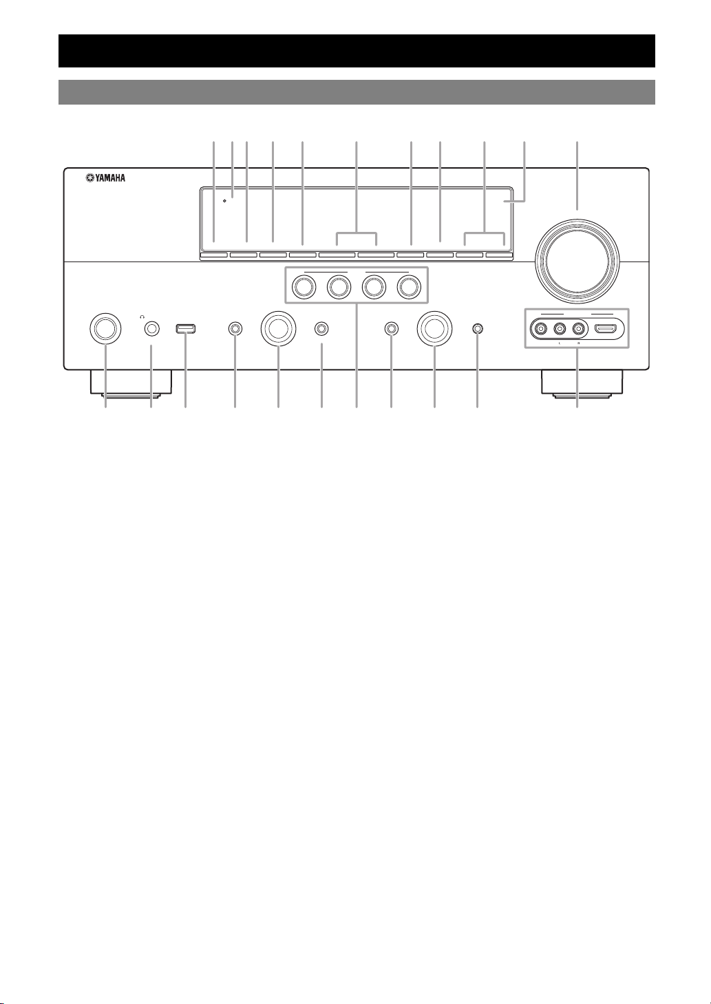
Front panel
ABC D E G HFIJK
Part names and functions
THROUGH
HDMI
VOLUME
ZONE3
MAIN ZONE
ON/OFF
PHONES
SILENT CINEMA
ZONE2
ON/OFF
USB
TONE CONTROL
ON/OFF
ZONE
CONTROLS
PROGRAM
l
INFO
BD/DVD
PRESET
SCENE
TV
STRAIGHT PURE DIRECT
EFFECT
h
MEMORY
RADIO
CD
LPSOQ T
A ZONE2 ON/OFF
Switches Zone2 on and off (page 71).
B HDMI THROUGH
Lights up in the following cases while this unit is on standby.
• when the HDMI control function is on
• when the HDMI signal standby-through function is currently
working
C ZONE3 ON/OFF
Switches Zone3 on and off (page 71).
D ZONE CONTROLS
Selects a zone to control with the main amplifier operations
(page 71).
E INFO
Changes information (input, DSP program, audio decoder, etc)
displayed on the front panel display (page 26).
F PRESET l / h
Selects an FM/AM preset station (page 32) or an XM/SIRIUS
preset channel (pages 37 and 41).
G MEMORY
Registers FM/AM stations as preset stations (page 32) or XM/
SIRIUS channels as preset channels (pages 37 and 41).
H BAND (CATEGORY)
Change the tuner bands between FM and AM.
Select a channel category for a XM/SIRIUS.
I TUNING/CH l / h
Changes FM/AM frequencies or XM/SIRIUS tuner channels.
J Front panel display
Displays information on this unit (page 6).
K VOLUME control
Controls the volume of this unit (page 24).
L MAIN ZONE ON/OFF
Turns this unit on and off (page 20).
M PHONES jack
For plugging headphones (page 26).
N USB port
For connecting a USB memory device or USB portable audio
player (page 19)
O TONE CONTROL
Adjusts high-frequency/low-frequency output of speakers
(page 25).
P PROGRAM selector
Changes sound field programs (page 27).
Q STRAIGHT
Toggles between the selected sound field program and straight
decode mode (page 30).
R SCENE
Switches between linked sets of input sources and sound field
programs (page 24).
S PURE DIRECT
Changes mode to Pure Direct mode (page 25). This key lights up
when Pure Direct mode is on.
T INPUT selector
Selects an input source (page 24).
U OPTIMIZER MIC jack
For connecting the supplied optimizer microphone and adjusting
output characteristics of speakers (page 21).
V VIDEO AUX jacks
For connecting a game console, camcorder or digital camera to
either the HDMI IN jack or analog AUDIO/VIDEO jacks
(page 19).
INPUT
BAND
CATEGORY
TUNING/CH
l
OPTIMIZER MIC
h
UMN R V
VIDEO
AUX
VIDEO
HDMI IN
AUDIO
4 En
Page 9
Rear panel
bca
dfeg
Part names and functions
INTRODUCTION
PHONO RS-232C
SIRIUS
DOCK
COMPONENT
VIDEO
OUT
R
P
OPTICAL
DIGITAL
AUDIO
B
P
GND
Y
OPTICAL
( TV )
AV
1
COAXIAL
AV 2
XM
(HDMI CONTROL)
ANTENNA
HD Radio
FM
UNBAL.
VIDEO
COAXIAL
OPTICAL
(CD)
AV 3
AV 4
TRIGGER OUT
12
12V
0.1A MAX.
HDMI 2
HDMI 1
HDMI OUT 2HDMI OUT 1
(BD/DVD)
MONITOR OUT
AM
GND
AV 6
AV 5
COMPONENT
VIDEO
R
P
VIDEO
B
P
Y
AUDIO1
AUDIO2
FRONT
AV
OUT
ijbhklmno
a SIRIUS jack
For connecting a SiriusConnect tuner (sold separately)
(page 39).
DOCK terminal
For connecting an optional Yamaha iPod universal dock (YDS-
11) or Bluetooth wireless audio receiver (YBA-10) (page 18).
XM jack
For connecting XM Mini-Tuner in XM Mini-Tuner Home Dock
(sold separately) (page 35).
b PHONO jacks
For connecting a turntable (page 16).
GND terminal
For connecting a turntable to reduce noise in the signal
(page 16).
c RS-232C terminal
Control expansion terminal for factory use only. Consult your
dealer for details.
d TRIGGER OUT 1/2 jacks
For connecting an external terminal with a trigger input terminal
to operate it linked with operation of this unit. Consult your
dealer for details.
e HDMI OUT 1/2 jacks
For connecting HDMI-compatible video monitors (page 14).
HDMI 1-4 jacks
For connecting external components for HDMI inputs 1-4
(page 16).
ANTENNA terminals
For connecting supplied FM and AM antennas (page 20).
MONITOR OUT jacks
Outputs visual signals from this unit to a video monitor, such as
a TV (page 14).
REMOTE IN/OUT jacks
For connecting an external component that supports the remote
control function (page 18).
HDMI 3
REMOTE
IN
OUT
SURROUND
SUR.BACK
MULTI CH INPUT
NETWORK
HDMI 4
SPEAKERS
FRONT
CENTER
ZONE3
SURROUND
FRONT
SURROUND
OUT
CENTER
SUBWOOFER
AUDIO
ZONE2
OUT
OUT
f NETWORK port
For connecting to the network (page 19).
g SPEAKERS terminals
For connecting front, center, surround and surround back
speakers (page 11). Connect the presence speakers (page 11) or
the speakers for Zone2/3 (page 70) to EXTRA SP terminals.
h DIGITAL AUDIO jack
Outputs audio signals from a selected digital audio input source
to an external component (page 16).
i AV 1-6 jacks
For connecting external components for audio/visual inputs 1-6
(page 16).
j AV OUT jacks
Outputs audio/visual signals from a selected analog input source
to an external component (page 16).
k AUDIO 1/2 jacks
For connecting external components for audio inputs 1-2
(page 16).
l MULTI CH INPUT jacks
For connecting a player that supports a multi-channel output
(page 18).
m AUDIO OUT jacks
Outputs audio signals from a selected analog input source to an
external component (page 16).
ZONE2/3 OUT jacks
Output sound of this unit to an external amplifier set in a
different zone (page 69).
n PRE OUT jacks
Outputs multi-channel signals from up to 7.1 channels to an
external amplifier (page 18).
o AC IN
For connecting the supplied power cable (page 20).
SP2 SP1
EXTRA SP
SURROUND BACK/
BI-AMP
CENTER
SINGLE
SUR. BACK SUBWOOFER
12
PRE OUT
SINGLE
ZONE2/PRESENCEZONE3
CLASS 2 WIRING
PREPARATION
AC IN
OPERATION
BASIC
OPERATION
ADVANCED
INFORMATION APPENDIX
ADDITIONAL
English
5 En
Page 10
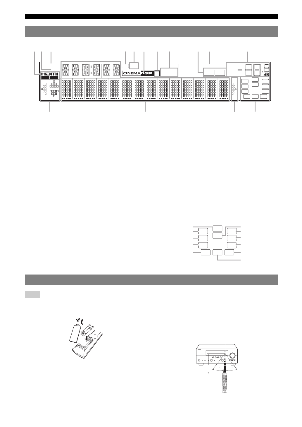
Part names and functions
ab gfdecjihk
lm nl
Front panel display
SIRIUS
XM
OUT 1 OUT 2
a HDMI indicator
Lights up during normal communication when HDMI is
selected as an input source.
OUT 1/OUT 2 indicators
The respective indicator lights up when HDMI signals are
output from the HDMI OUT 1/2 jacks.
b XM indicator
Lights up when an XM tuner is selected as an input source.
c SIRIUS indicator
Lights up when a SiriusConnect tuner is selected as an input
source.
d HD indicator
Lights up when this unit is tuned into the HD Radio reception
band (page 33).
e TAG indicator
Lights up when the selected HR Radio program (or song being
played) supports the iTunes Tagging feature (page 33).
f CINEMA DSP indicator
Lights up when a sound field program that uses CINEMA DSP
is selected.
g CINEMA DSP 3D indicator
Lights up when CINEMA DSP 3D is activated.
h Tuner indicator
Lights up during receiving radio broadcast signals from an FM/
AM station (page 31).
HD
TAG
STEREO
3
TUNED
SLEEP
ZONE2ZONE
VOL.
3
MUTE
PL PR
LR
SL SR
SBL SB SBR
i ZONE2/ZONE3 indicator
Lights up when Zone2 or Zone3 is turned on.
j SLEEP indicator
Lights up when the sleep timer is activated (page 53).
k MUTE indicator
Flashes when audio is muted.
VOLUME indicator
Displays volume levels.
l Cursor indicators
Light up if corresponding cursors on the remote control are
available for operations.
m Multi information display
Displays menu items and settings for the current operation.
n Speaker indicators
Indicate speaker terminals from which signals are currently
output.
Subwoofer
Presence L Presence R
Front L
Surround L
Surround back L
SW
PL PR
C
LR
SL SR
SBL SB SBR
Center
Front R
Surround R
Surround back R
Surround back
SW
C
Remote control
Note
• Before installing batteries or using the remote control, make sure that you read “Notes on remote controls and batteries” in the “Caution” section.
■ Installing batteries
a
c
b
a Take off the battery compartment cover.
b Insert the two supplied batteries (AAA, R03, UM-4)
according to the polarity markings (+ and -) on the
inside of the battery compartment.
c Snap the battery compartment cover back into the
place.
6 En
■ Operation range
The remote control transmits a directional infrared ray. Be
sure to aim the remote control directly at the remote
control sensor on this unit during operation.
Remote control sensor window
within 6 m (20 ft)
30 30
Page 11
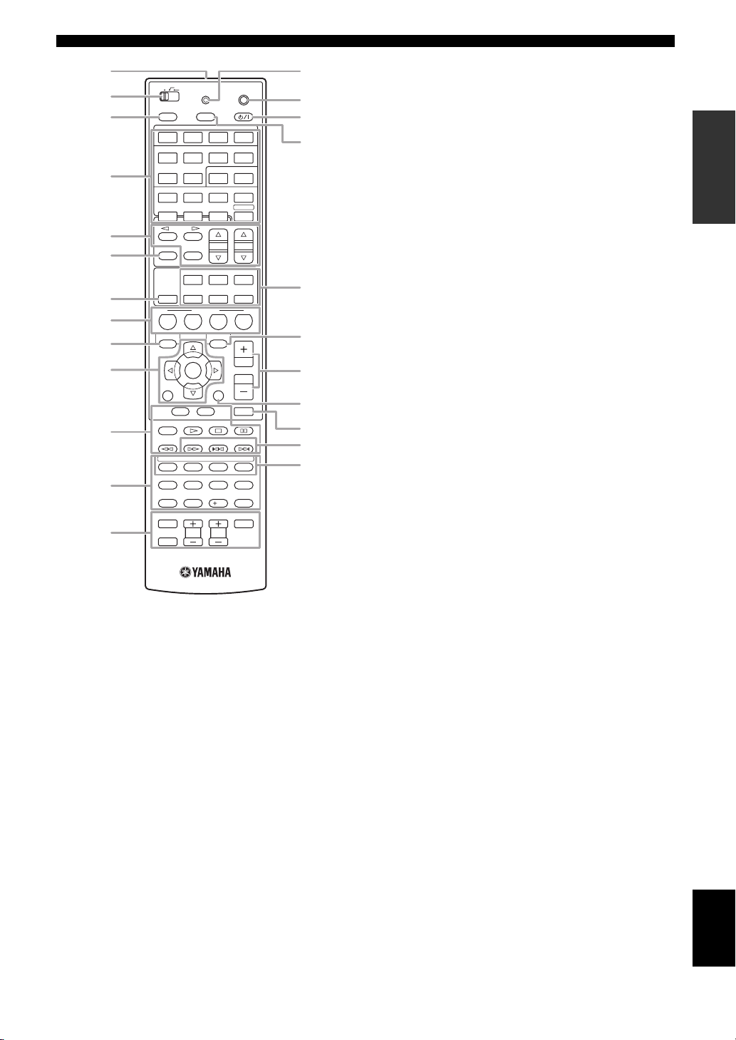
Part names and functions
n
a
ZONE 2
MAIN
b
c
d
e
f
g
h
i
j
k
ZONE 3
POWER
1 2 3
1 2 3
5 6 1
HDMI
PHONO
V-AU X
TUNER SIRIUS
CATEGORY
FM AM
INFO
MEMORY
MUSIC
HDMI OUT
MOVIE
BD
TV
DVD
ON SCREEN OPTION
ENTER
RETURN
TOP
MENU
REC
TAG PRG SELECT
USB NET RADIO PC RHAPSODY
1234
l
90
INPUT
m
a Remote control signal transmitter
Transmits infrared signals.
b Zone selection switch
Switches amplifiers (main, Zone2 or Zone3) to be operated by
the remote control (page 71).
c SOURCE POWER
Switches an external component on and off.
d Input selection keys
HDMI 1-4
AV 1- 6
AUDIO 1/2
V-AUX
PHONO
MULTI
DOCK
TUNER
SIRIUS
XM
USB/NET
Selects HDMI inputs 1 through 4.
Selects AV inputs 1 through 6.
Selects AUDIO inputs 1 and 2.
Selects a signal input from the VIDEO AUX jacks.
Selects a signal input from the PHONO jacks.
Selects a signal input from the MULTI CH
INPUT jacks.
Selects a Yamaha iPod universal dock/Bluetooth
wireless audio receiver connected to the DOCK terminal.
Selects the FM/AM tuner.
Selects a SiriusConnect tuner as an input source.
Selects an XM tuner as an input source.
Selects a USB device or a signal input via
network (selected by xSub-input
selection keys).
MUTE
TV VOL
TRANSMIT
SLEEPSOURCE
HDMI
AV
AUDIO
MULTI
XM
PRESET
ENHANCER SUR. DECODE
STEREO
STRAIGHT
SCENE
CD
DISPLAY
POP-UP
MENU
7856
10
TV
TV CH
CODE SET
POWER
4
4
2
DOCK
USB/NET
TUN./CH
PURE DIRECT
RADIO
VOLUME
MUTE
ENT
POWER
o
p
q
r
s
t
u
v
w
x
e Tuner keys
FM/AM
(CATEGORY l / h)
Switches a band between FM and AM.
Select a channel category for XM/
SIRIUS.
MEMORY
PRESET k / n
TUN./CH k / n
Presets radio stations.
Selects a preset station.
Changes FM/AM frequencies or
XM/SIRIUS tuner channels.
f INFO
Changes the information shown on the front panel display
(page 26).
g HDMI OUT
Switches the HDMI OUT jacks to output HDMI signals
(page 53).
h SCENE
Switches between linked sets of input sources and sound field
programs (page 24).
i ON SCREEN
Displays the GUI screen (page 25).
j Cursors k / n / l / h
Select menu items or change
settings.
ENTER
RETURN
Confirms a selected item.
Returns to the previous screen or
ends the menu display.
k External component operation keys
Operate recording, playback etc. of external components
(page 72).
l Numeric keys
Enter numbers.
m TV control keys
Enables operations of a TV or a projector (page 72).
n TRANSMIT
Lights up when a signal is output from the remote control.
o CODE SET
Sets remote control codes for external component operations
(page 72).
p POWER
Switches this unit on and standby (page 20).
q SLEEP
Switches the sleep timer operations (page 53).
r Sound selection keys
Selects sound field programs (page 27).
s OPTION
Displays the Option menu (page 54).
t VOLU ME +/–
Adjust the volume of this unit (page 24).
u DISPLAY
Displays the play information on the video monitor.
When an iPod is connected: Changes the operation mode of the
iPod connected to the Yamaha iPod universal dock (page 44).
v MUTE
Turns the mute function on and off (page 25).
w HD Radio keys
TAG
Stores “tag” data to the iPod or internal
memory of this unit (page 33).
PRG SELECT
Selects an HD Radio audio program
(page 33).
x Sub-input selection keys
Selects USB, NET RADIO, PC or Rhapsody when “USB/NET”
is selected as the input source.
INTRODUCTION
PREPARATION
OPERATION
BASIC
OPERATION
ADVANCED
INFORMATION APPENDIX
ADDITIONAL
English
7 En
Page 12
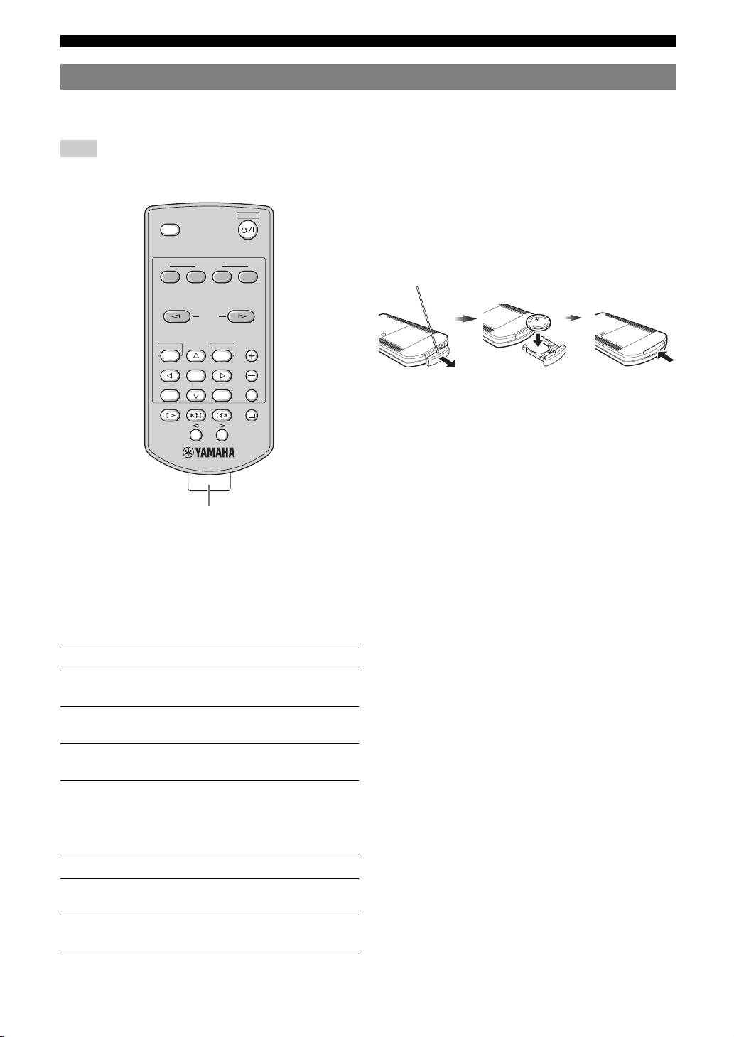
Part names and functions
Simplified remote control
Use the supplied simplified remote control to make basic controls of this unit. Keys on the simplified remote control
function as well as the identical keys on the main remote control (page 6).
Note
• Before using the simplified remote control or replacing the battery, make sure that you read “Notes on remote controls and batteries” in the “Caution”
section.
POWER
SLEEP
SCENE
BD
TV CD
DVD
ON SCREEN
ENTER
TAG
PRG SELECT
Remove the insulation sheet
y
• To select an input source, press INPUT l / h repeatedly.
• The printings “TAG” and “PRG SELECT” are for U.S.A. model.
INPUT
PRESET
OPTION
DISPLAYRETURN
RADIO
VOLUME
MUTE
■ Setting the controlling zone
Follow the procedure below to select an amplifier (main,
Zone2 or Zone3) to be operated by the simplified remote
control (page 71).
Zone to select Procedure
Main Press and hold h (right of ENTER) and
BD/DVD for more than 3 seconds.
Zone2 Press and hold h (right of ENTER) and TV
for more than 3 seconds.
Zone3 Press and hold h (right of ENTER) and CD
for more than 3 seconds.
■ Replacing the battery of the simplified
remote control
Change the battery when the operation range of the
simplified remote control decreases.
Use a straight
pin to remove
the cover.
Replace the
battery with a
new CR2025
battery.
Close the
cover.
■ Setting the remote control ID
Follow the procedure below to set the remote control ID of
the simplified remote control. For details about remote
control ID, see page 74.
Zone to select Procedure
ID1 Press and hold l (left of ENTER) and BD/
DVD for more than 3 seconds.
ID2 Press and hold l (left of ENTER) and TV
for more than 3 seconds.
8 En
Page 13
Quick start guide
When you use this product for the first time, perform setup following the steps below. See the related pages for details on
operations and settings.
Step 1: Prepare items for setup
Step 2: Set up your speakers
INTRODUCTION
Prepare speakers, DVD player, cables, and other items
necessary for setup.
For example, prepare the following items for setting up a
7.1-channel sound system.
Front right speaker
Video monitor
Front left
speaker
Center
speaker
Components
(such as DVD player)
Surround left speaker
Requirements qty.
Speakers Front speaker 2
Active subwoofer 1
Speaker cable 7
Subwoofer cable 1
Reproduction component such as DVD player 1
Video monitor such as TV 1
Video cable or HDMI cable 2
Audio cable 2
y
• The priority of the requirement of other speakers is as follows:
1 Two surround speakers
2 One center speaker
3 One (or two) surround back speaker(s)
• Video and audio cables are unnecessary if you use HDMI cables.
Subwoofer
Surround right speaker
Surround Back
right speaker
Surround Back
left speaker
Center speaker 1
Surround speaker 2
Surround back
speaker
2
Place your speakers in the room and connect them to this
unit.
• Placing speakers ☞P. 1 0
• Connecting speakers ☞P. 1 1
y
• This unit has a YPAO (Yamaha Parametric Room Acoustic Optimizer)
that automatically optimizes this unit based on room acoustic
characteristics (audio characteristics of the speakers, speaker positions,
and room acoustics, etc.).
You can enjoy good balanced sound without special knowledge by using
the YPAO technology (☞P. 21).
Step 3: Connect your components
Connect your TV, DVD player, or other components.
• Connecting a TV monitor or projector ☞P. 1 4
• Connecting other components ☞P. 1 6
• Connecting a multi-format player or an
external decoder ☞P. 1 8
• Connecting an external amplifier ☞P. 1 8
• Connecting a USB storage device ☞P. 1 9
• Connecting a Yamaha iPod universal dock or
Bluetooth wireless audio receiver ☞P. 1 8
• Connecting to the network ☞P. 1 9
• Connecting the FM and AM antennas ☞P. 2 0
• Connecting an XM Mini-Tuner Home Dock ☞P. 3 5
• Connecting a SiriusConnect tuner ☞P. 3 9
Step 4: Turn on the power
Connect the power cable and turn on this unit.
• Connecting the power cable ☞P. 20
• Turning this unit on and off ☞P. 2 0
Step 5: Select the input source and start
playback
Select the component connected in step 3 as an input
source and start playback.
• Basic procedure ☞P. 2 4
• Selecting sound field programs ☞P. 2 7
y
• This unit supports the SCENE function (page 24) that changes the input
source and sound field program at one time. Four scenes are preset for
different purposes for Blu-ray disc, DVD and CD, and you can select
from a scene from those just by pressing a remote control key.
PREPARATION
OPERATION
BASIC
OPERATION
ADVANCED
INFORMATION APPENDIX
ADDITIONAL
9 En
English
Page 14
PREPARATION
Connections
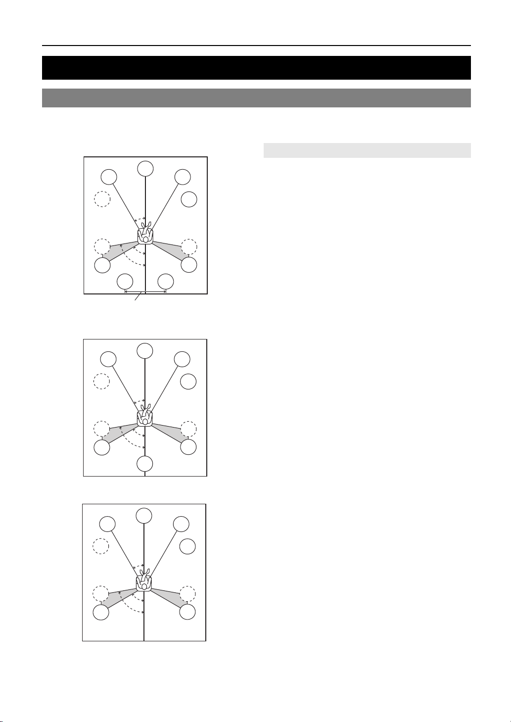
Placing speakers
This unit supports up to 7.1-channel surround. We recommend the following speaker layout in order to obtain the
optimum surround effect.
7.1-channel speaker layout
Speaker channels
80˚
SBL
C
30˚
60˚
FL
SW
SL
SL
30 cm (12 in) or more
6.1-channel speaker layout
FL
SW
SL
SL
C
30˚
60˚
80˚
SB
5.1-channel speaker layout
FL
SW
SL
SL
C
30˚
60˚
80˚
SBR
FR
The front speakers are used for the front channel sounds
(stereo sound) and effect sounds. Place these speakers at
■ Front left and right speakers (FL and FR)
SW
an equal distance from the ideal listening position. Adjust
the height of the TV or screen so that about 1/4 of the
screen from the bottom is aligned with the tweeters of the
front speakers.
SR
SR
■ Center speaker (C)
The center speaker is for the center channel sounds
(dialog, vocals, etc.). Place it halfway between the left and
right speakers. When using a TV, place the speaker just
above or just under the center of the TV with the front
surfaces of the TV and the speaker aligned. When using a
screen, place it just under the center of the screen.
■ Surround left and right speakers (SL and SR)
The surround speakers are used for effect and surround
FR
SW
sounds. Place them at the rear left and rear right facing the
listening position. To obtain a natural sound flow in the
5.1-channel speaker layout, place them slightly further
back than in the 7.1-channel speaker layout.
■ Surround back left and right speakers (SBL
and SBR) / Surround back speaker (SB)
SR
The surround back left and right speakers are used for rear
effect sounds. Place them at the rear of the room facing the
SR
listening position at least 30 cm (1 ft) away from each
other, ideally at the same distance as that between the
front left and right speakers.
In the 6.1-channel speaker layout, surround back left and
right channel sound signals are mixed down and output
from the single surround back speaker.
In the 5.1-channel speaker layout, surround back left and
FR
right channel sound signals are output from the surround
left and right speakers.
SW
■ Subwoofer (SW)
The subwoofer speaker is used for bass sounds and lowfrequency effect (LFE) sounds included in Dolby Digital
and DTS signals. Use a subwoofer with a built-in
SR
SR
amplifier, such as the Yamaha Active Servo Processing
Subwoofer System. Place it exterior to the front left and
right speakers facing slightly inward to reduce reflections
from a wall.
10 En
Page 15
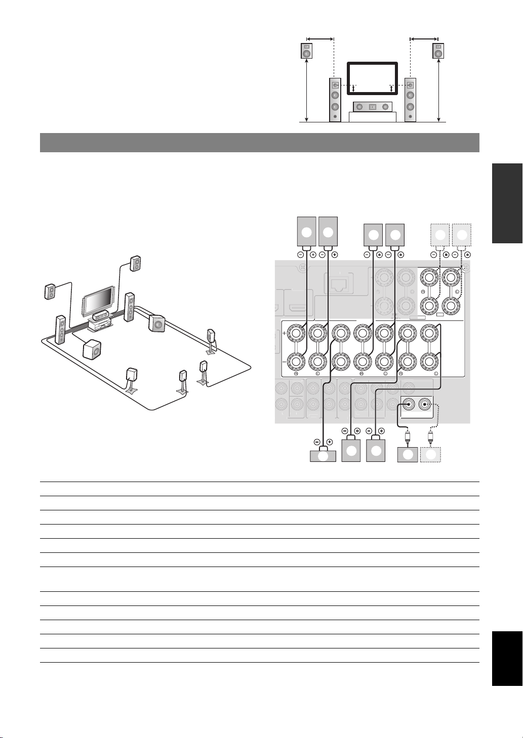
■ Presence left and right speakers (PL and PR)
k
SP
SU
CK
SUBWOOFER
T
U
O
ZONE3
OU
ZONE2
OUT
FR
ONT
S
CK
P
OUT
C
SINGLE
HDMI
C
EXTR
The presence speakers supplement the sound from the
front speakers with extra ambient effects produced by the
sound field programs (page 27). We recommend that you
use the presence speakers especially for the CINEMA
DSP sound field programs. To use the presence speakers,
connect the speakers to SP1 terminals and then set “Extra
Speaker Assignment” to “Presence” (page 60).
Connecting speakers
1.8 m
(6 ft)
FL
1/4 from
bottom
C
0.5 to 1 m (1 to 3 ft)0.5 to 1 m (1 to 3 ft)
PRPL
FR
1.8 m
(6 ft)
INTRODUCTION
Connect your speakers to the respective terminals according to your speaker layout. The following illustration shows how
to connect speakers for 7.1-channel speaker layout.
y
• You can connect Zone2/3 speakers to the EXTRA SP (SP1/SP2) terminals (page 70).
• You can connect up to two subwoofers. When two subwoofers are connected, the same sound is output from them.
j
a
c
b
b a
4
e
e d
ORK
SPEAKERS
A
k j
ZONE2/PRESENCE
SINGLE
SP1
CLASS 2 WIRING
h
i
d
f
g
INPU
RE
SURROUND BACK/
BI-AMP
ENTER
SUBWOOFER
12
h i
FRONT
ENTER
R.B
CENTER
SURROUND
DIO
UT
c
T
g f
URROUNDSUR. BA
PREPARATION
OPERATION
BASIC
OPERATION
ADVANCED
INFORMATION APPENDIX
ADDITIONAL
Speakers Jacks on this unit 7.1-channel 6.1-channel 5.1-channel
a Front left FRONT (L) ✔✔✔
b Front right FRONT (R) ✔✔✔
c Center CENTER ✔✔✔
d Surround left SURROUND (L) ✔✔✔
e Surround right SURROUND (R) ✔✔✔
f Surround back left
(Surround back for 6.1-channel)
SURROUND BACK (L)
(SINGLE)
✔✔
g Surround back right SURROUND BACK (R) ✔
h Subwoofer 1 SUBWOOFER 1 ✔✔✔
i Subwoofer 2 SUBWOOFER 2 Option Option Option
j Presence left SP1 (L) Option Option Option
English
k Presence right SP1 (R) Option Option Option
11 En
Page 16
Connections
Caution
• A speaker cable is a pair of insulated cables running side by side in general. One of the cables is colored differently
or striped to indicate a polarity. Connect one end of the colored/striped cable to the “+” (red) terminal of this unit
and the other end to that of your speaker, and connect one end of the other cable to the “–” (black) terminal of this
unit and the other end to that of your speaker.
• Before connecting the speakers, be sure to disconnect the power cable.
• Do not let the bare speaker wires touch each other or any metal part of this unit. This could damage this unit and/or
speakers. If the circuit shorts out, “CHECK SP WIRES!” appears on the front panel display when this unit is turned
on.
• If images on the monitor (CRT) are distorted, place the speakers away from the video monitor.
• Use speakers with an impedance of 6-ohm or larger. Set speaker impedance in the advanced setup menu before
connecting the speakers (page 73). You can also use 4-ohm speakers as the front speakers when you set “SP IMP.” to
“6ΩMIN”.
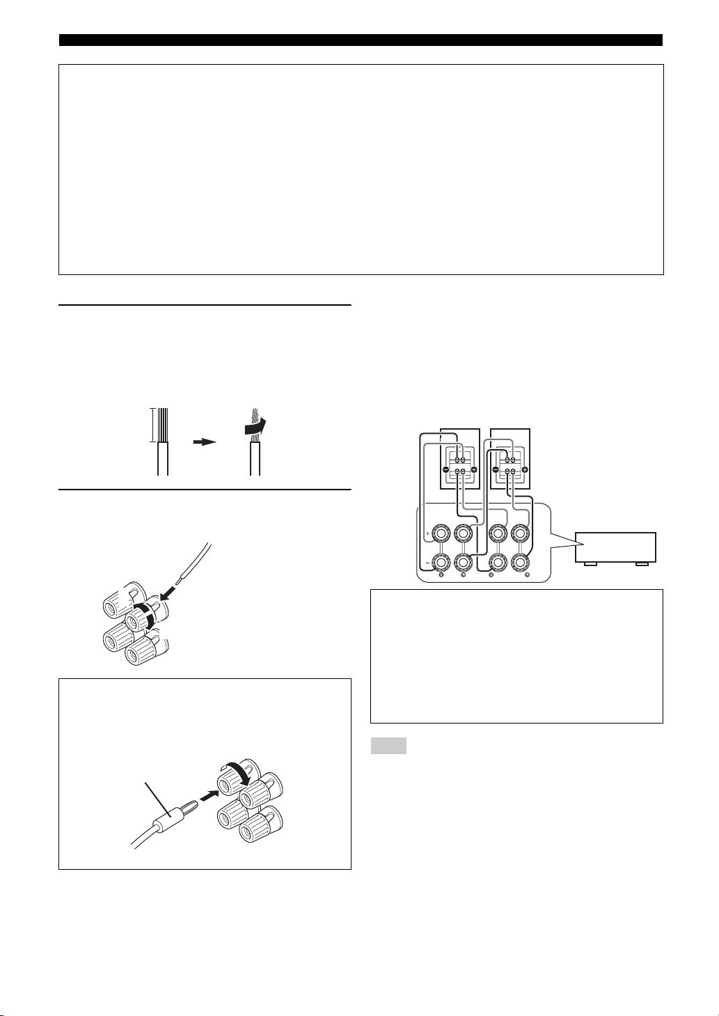
■ Connecting speaker cables
1 Remove approximately 10 mm (0.4 in) of
insulation from the end of each speaker
cable and then twist bare wires of the cable
together so that they will not cause a short
circuits.
10 mm (0.4 in)
2 Loosen the knob, insert the twisted bare
wires into the hole and then tighten the knob.
2
1
Red: positive (+)
Black: negative (–)
3
Connecting the banana plug (Except Korea,
U.K., Europe, Russia and Asia models)
Tighten the knob and then insert the banana plug into
the end of the terminal.
Banana plug
■ Using bi-amplification connections
If you do not connect surround back speakers, you can use
the SURROUND BACK/BI-AMP jacks to make biamplification connections to one speaker system which
supports bi-amplification connection as shown below.
To activate the connections, set “BI-AMP” to “ON” in the
advanced setup menu (page 73).
Front speakers
Right Left
This unit
FRONT
SURROUND BACK/
BI-AMP
Caution
Before making bi-amplification connections, remove
any brackets or cables that connect a woofer with a
tweeter. Refer to the instruction manuals of speakers for
details.
When not making bi-amplification connections, make
sure that the brackets or cables are connected before
connecting the speaker cables.
Note
• You cannot use surround back speakers or extra speakers (presence and
Zone2 speakers) when bi-amplification connections are made.
12 En
Page 17
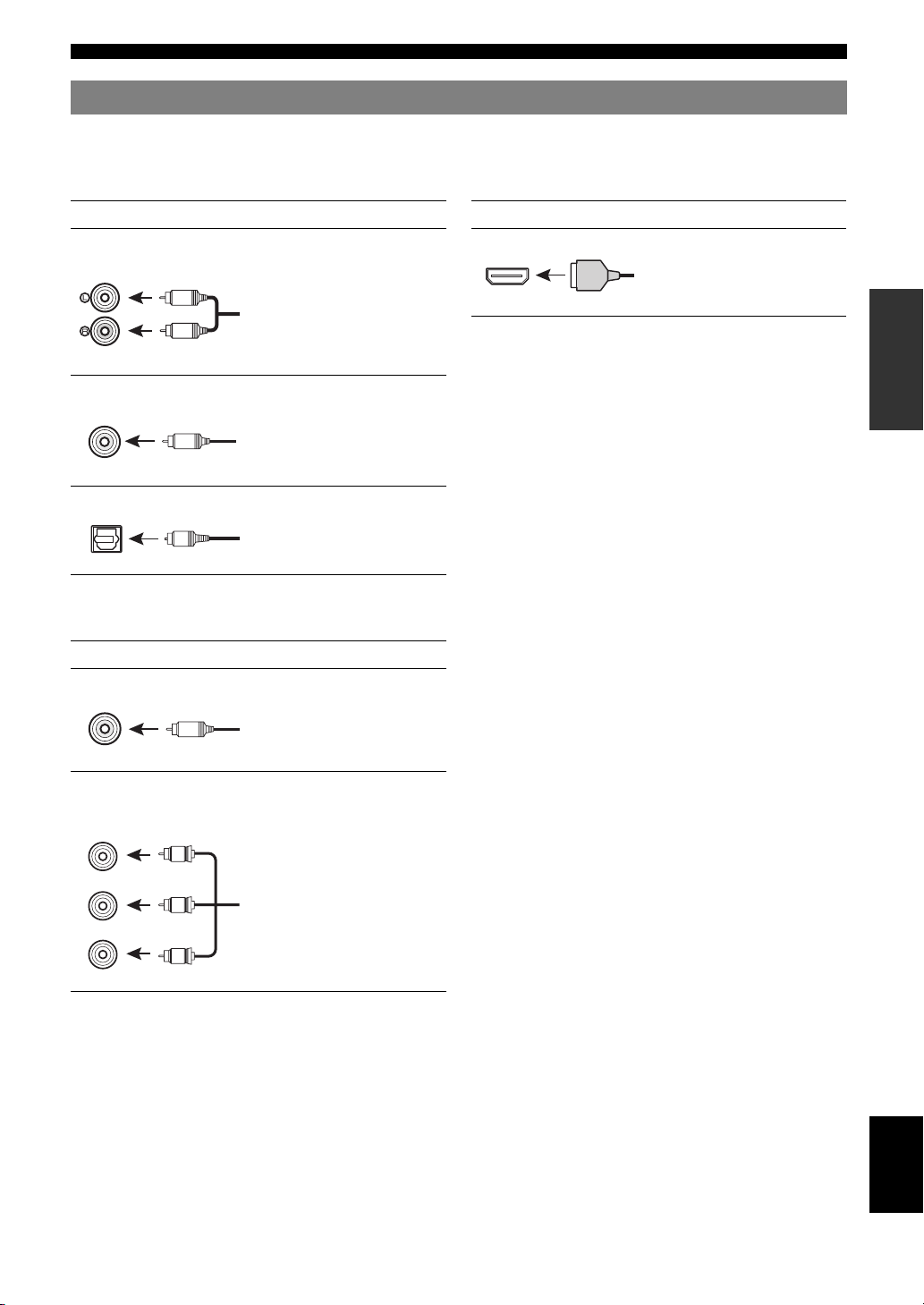
Information on jacks and cable plugs
Connections
This unit has the following input and output jacks. Use jacks and cables appropriate for components that you are
connecting.
■ Audio jacks
Jack and cables Description
Analog audio jacks To transmit conventional analog
(white)
L
R
(red)
COAXIAL jacks To transmit coaxial digital audio
(orange)
C
COAXIAL
OPTICAL jacks To transmit optical digital audio
O
OPTICAL
stereo audio signals. Use stereo pin
cables.
signals. Use pin cables.
signals. Use optical fiber cables.
■ Video/audio jacks
Jack and cables Description
HDMI jacks To transmit digital video and
HDMI
y
• We recommend that you use a commercially available 19-pin HDMI
cable no longer than 5 meters (16 feet) with the HDMI logo printed on it.
• Use a conversion cable (HDMI jack ↔ DVI-D jack) to connect this unit
to other DVI components.
• You can check the potential problem about the HDMI connection
(page 55).
HDMI
digital audio signals. Use HDMI
cables.
■ Video jacks
Jack and cables Description
VIDEO jacks To transmit conventional
VIDEO
V
(yellow)
COMPONENT VIDEO
jacks
COMPONENT
VIDEO
R
PR
(red)
PB
(blue)
Y
(green)
P
P
B
Y
composite video signals. Use pin
cables.
To transmit component video
signals that include luminance (Y),
chrominance blue (PB) and
chrominance red (PR) components.
Use component video cables.
INTRODUCTION
PREPARATION
OPERATION
BASIC
OPERATION
ADVANCED
INFORMATION APPENDIX
ADDITIONAL
13 En
English
Page 18
Connections
T
UNB
adio
HDMI
(
)
H
2
H
O
MONIT
OR OU
V
0
.
P
R
O
TE
COMPO
O
X
OR OU
T
O
H
HDMI
(
)
H
2
O
O
12V
0
.
REMO
TE
M
T
V
O
H
H
HDMI
(
VD
)
H
OU
V
.
O
TE
COMPO
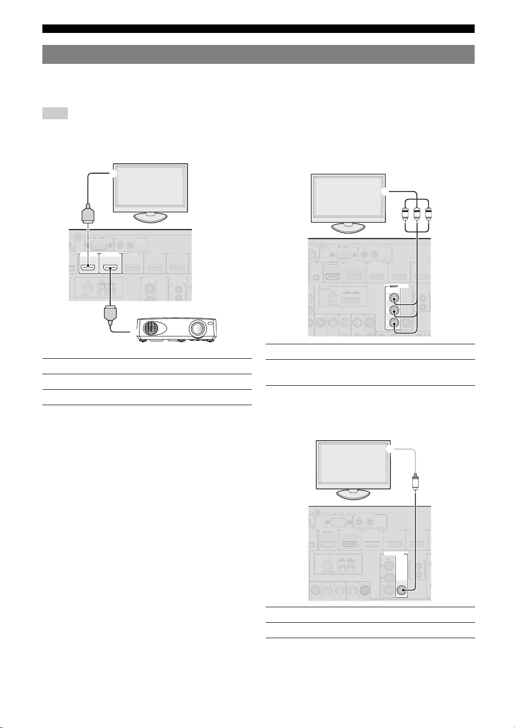
Connecting a TV monitor or projector
According to the types of video input jacks available on your video monitor (such as a TV or projector), choose one of
the connection methods as shown below. When you connect video players such as a DVD player to this unit with an
HDMI connection, connect your video monitor to this unit with an HDMI connection.
Note
• Make sure that this unit and other components are unplugged from the AC wall outlets.
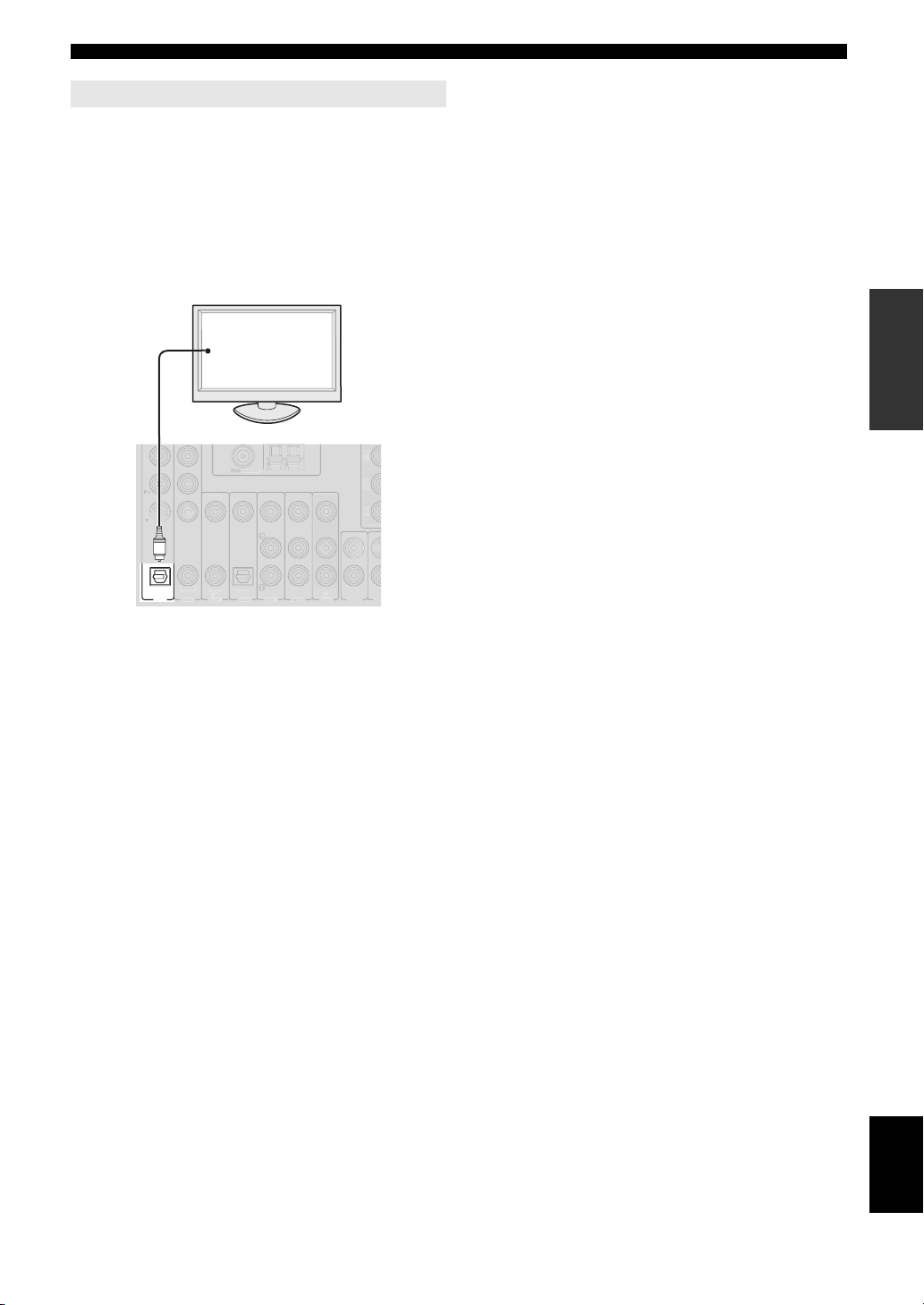
■ If your video monitor has an HDMI input jack
TV
a
HDMI
RIGGER OUT
12
.1A MAX
M
HDMI OUT 2HDMI OUT 1
(HDMI CONTROL)
HD R
HDMI
Jacks on components Jacks on this unit
a HDMI input HDMI OUT 1
b HDMI input HDMI OUT 2
y
• This unit is equipped with two HDMI OUT jacks. You can select the
active HDMI OUT jack(s) by pressing gHDMI OUT (page 53).
• This unit supports the HDMI control function (page 53). If your TV
supports the HDMI control function, connect the TV to the HDMI OUT
1 jack to control this unit with the remote control of your TV.
DMI
1
BD/D
DMI 3
T
NENT
VIDE
REM
UT
b
Projector
■ If your video monitor does not have HDMI
input jacks but component video input jacks
TV
c
R
PBYP
RIGGER OUT
.1A MAX
DMI
DMI OUT 2
VIDE
1
BD/D
COMPONENT
R
P
B
P
Y
HDMI 3
T
VIDEO
UT
VIDE
Jacks on components Jacks on this unit
c Component video output MONITOR OUT
(COMPONENT VIDEO)
■ If your video monitor has neither HDMI nor
component video input jacks
TV
d
V
RIGGER OUT
12
0.1A MAX
ONITOR OUT
NENT
DMI 3
REM
T
VIDEO
IDE
HD Radio
DMI OUT 1
DMI OUT 2
1
BD/D
Jacks on components Jacks on this unit
d Video input (composite) MONITOR OUT (VIDEO)
14 En
Page 19
Outputting TV sounds from this unit
(
)
V 1
CO
A
L
A
V 3
(CD)
CO
L
O
A
V 4
V 5
A
V 6
O
A
UDIO1
A
UD
O
UNB
AL
P
B
To output sound of a TV from this unit, make connection
between one of the AV 1-6 jacks of this unit and an audio
output jack of the TV.
If the TV supports an optical digital output, we
recommend that you use the AV 1 jack. Connecting to the
AV 1 jack allows you to switch an input source to the AV 1
jack with a just a single key operation using the SCENE
function (page 24).
TV
Digital output
(optical)
Connections
INTRODUCTION
PREPARATION
OPTICAL
TV
.
VIDE
OPERATION
BASIC
O
XIA
AXIA
PTICAL
UT
OPERATION
ADVANCED
INFORMATION APPENDIX
ADDITIONAL
English
15 En
Page 20
Connections
RS
C
TRIGG
N
OU
H
1
UNBAL.
adio
GND
AM
(
OL
)
V
O
OU
MO
OUT
12V
0.1A MAX.
F
P
B
Y
C
O
S
S
XM
Connecting other components
This unit has input and output terminals for respective input and output sources. You can reproduce sound and movies
from input sources selected with the front panel display or remote control.
Note
• Make sure that this unit and other components are unplugged from the AC wall outlets.
Audio input (PHONO)
Audio / video output (AV OUT)
PHONO
IRIU
Audio output
(DIGITAL AUDIO)
OUT
OPTICAL
DIGITAL
AUDIO
GND
DOCK
COMPONENT
VIDEO
P
R
P
B
Y
HD R
VIDEO
GND terminal
COAXIAL
Audio / video input
(AV 1-6)
OPTICAL
COAXIAL
(
)
TV
A
V
(CD)
AV 2
AV 3
1
■ Audio and video player / Set-top box
External
component
External component
with HDMI output
External component
with component video
output
External component
with composite video
output
Signal
Audio/Video HDMI output HDMI 1 (BD/DVD)
Audio Optical digital output AV 1 (TV) OPTICAL
Video Component video output COMPONENT VIDEO
Audio Coaxial digital output AV 2 COAXIAL
Video Component video output COMPONENT VIDEO
Audio Coaxial digital output AV 3 (CD) COAXIAL
Video Composite output VIDEO
Audio Optical digital output AV 4 OPTICAL
Video Composite output VIDEO
Audio Analog audio output AV 5 Analog audio
Video Composite output VIDEO
Audio Analog audio output AV 6 Analog audio
Video Composite output VIDEO
Output jacks on
components
232
HDMI OUT 2
DMI OUT
HDMI CONTR
OPTICAL
AV 6
AV 4
AV 5
Audio input (AUDIO 1/2)
ER OUT
HDMI 1
(
BD/DVD
AV
OUT
HDMI 2
HDMI 3
HDMI 4
HDMI 3
REMOTE
T
SUR.BACK
HDMI 4
CENTER
SUBWOOFER
HDMI input
(HDMI 1-4)
RONT
Audio output
(AUDIO OUT)
AUDIO
ZO
OUT
HDMI 2
)
NITOR
OMPONENT
VIDE
IDE
SURROUND
FRONT
AUDIO2
AUDIO1
MULTI CH INPUT
Multi channel audio input (MULTI CH INPUT)
Input jacks on this unit
16 En
Page 21
Connections
y
• Input jacks in parentheses indicate the jacks to which the SCENE function (page 24) is assigned by the initial factory settings. To use the SCENE function
with the initial factory settings, connect external components that support the SCENE function to these jacks.
• You can change the name of the input source displayed on the front panel display as necessary (page 64).
• See page 69 on how to use the ZONE2/3 OUT jacks.
• When you connect an external component with analog audio and component video (or composite) output jacks, connect the analog audio output to the
AUDIO 1 or AUDIO 2 jacks of this unit while making a video connection (component video or composite). Then select the video to be output when
“AUDIO 1” or “AUDIO 2” is selected as the input source (page 56).
■ Audio player
External component
External component with optical digital
output
External component with coaxial digital
output
External component with analog audio
output
Turntable Analog audio output PHONO Analog audio
y
• If your CD player has a coaxial digital output jack, connect it to the AV3 jack of this unit. In this case, you can use the SCENE function (page 24) with the
initial factory settings.
• When connecting a turntable with a low-output MC cartridge to the PHONO jacks, use an in-line boosting transformer or MC-head amplifier.
• Connect your turntable to the GND terminal of this unit to reduce noise in the signal.
Output jacks on
components
Input jacks on this unit
Optical digital output AV 1 (TV) OPTICAL
AV 4 OPTICAL
Coaxial digital output AV 2 COAXIAL
AV 3 (CD) COAXIAL
Analog audio output AV 5 Analog audio
AV 6 Analog audio
AUDIO 1 Analog audio
AUDIO 2 Analog audio
About audio/video output jacks
When using the AV OUT jacks: connect these jacks to composite video and analog audio input jacks of an external
component.
When using the AUDIO OUT jacks: connect these jacks to analog audio input jacks of an external component.
When using the DIGITAL AUDIO (OPTICAL OUT) jack: connect this jack to optical digital input jack of an
external component.
INTRODUCTION
PREPARATION
OPERATION
BASIC
OPERATION
ADVANCED
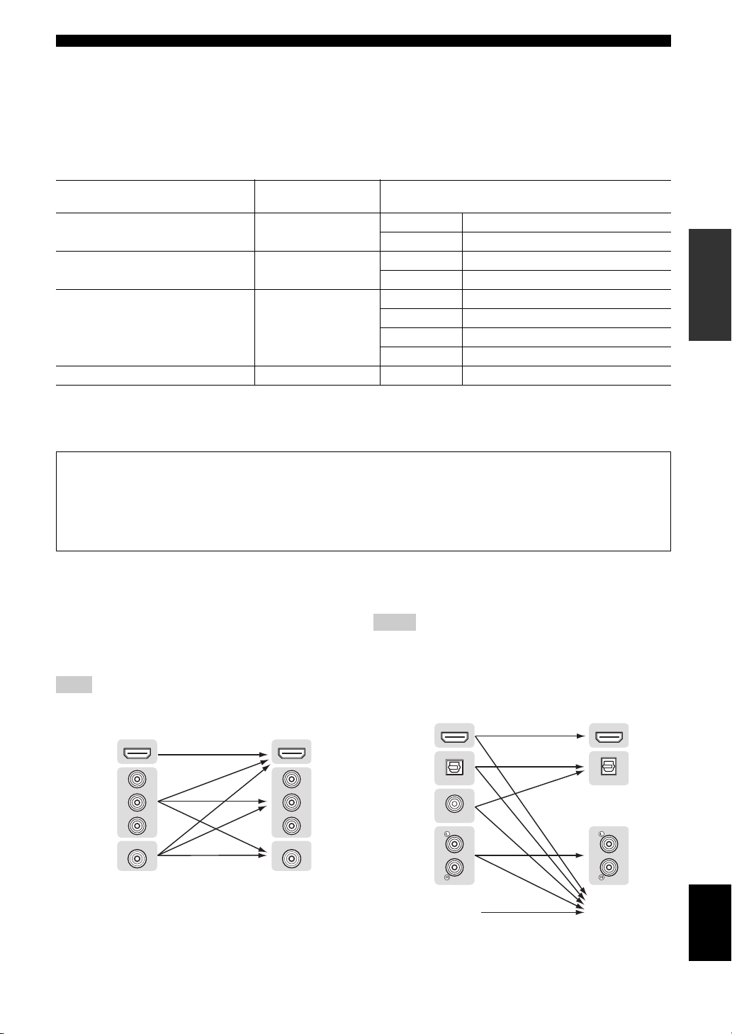
■ Internal signal flow
Video signal flow
This unit automatically converts input video signals and
outputs the signals to the HDMI OUT jacks and
MONITOR OUT (COMPONENT VIDEO and VIDEO)
jacks (video conversion).
Note
• The AV OUT (composite video) jack only outputs video signals input to
the composite video input jacks.
Input Output
HDMI
Component
video
Composite
video
HDMI
P
R
B
P
Y
VIDEO
P
P
Y
HDMI OUT
R
B
VIDEO
Audio signal flow
Notes
• Audio signals input to the HDMI input jacks are output from either the
speaker terminals or HDMI OUT 1/2 jacks depending on the “Audio
Output” setting (page 62).
• The DIGITAL AUDIO (OPTICAL OUT) jack outputs digital audio
signals only when signals are input to the optical or coaxial optical input
jacks and corresponding input source is selected.
Input Output
HDMI
Optical
digital
Coaxial
digital
Analog
MULTI CH INPUT
HDMI
OPTICAL
COAXIAL
HDMI OUT
OUT
OPTICAL
Speaker
terminals
INFORMATION APPENDIX
ADDITIONAL
English
17 En
Page 22
Connections
e
)
HDMI 2
HDMI
HDMI 4
O
MO
P
R
COMPO
T
O
PHONORS232C
O
COMPO
V
O
1
OU
H
UNB
H
adio
G
(
BD
(
)
S
S
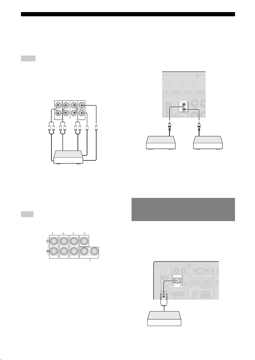
■ Connecting a multi-format player or an
external decoder
This unit is equipped with 8 additional input jacks (Front
L/R, Center, Surround L/R, Surround Back L/R and
Subwoofer) for analog multi-channel input from a multiformat player, external decoder, etc.
Notes
• When you select “MULTI CH” as the input source, the digital sound field
processor is automatically disabled.
• Since this unit does not redirect signals input at the MULTI CH INPUT
jacks to accommodate for missing speakers, connect at least a 5.1channel speaker system when using this feature.
• You can specify a video signal to be output during a multi-channel audio
reproduction (page 56). If your DVD player has analog multi-channel
output jacks, connect them to the MULTI CH INPUT jacks while making
a video connection (component video or composite).
CENTER
SURROUND
FRONT
SUR.BACK
SUBWOOFER
MULTI CH INPUT
LRLR RL
Surround
back out
Surround
out
Front out
Multi-format player or external decoder
(7.1-channel output)
Subwoofer out
Center out
■ Connecting an external amplifier
If you want to use another amplifier, connect an external
amplifier to the PRE OUT jacks. Each PRE OUT jack
outputs the same channel signals as the corresponding
speaker terminals.
Note
• When you make connections to the PRE OUT jacks, do not make any
connections to the speaker terminals.
abc d
CENTERSINGLE
FRONT
SURROUND
PRE OUT
a FRONT PRE OUT jacks
Front channel output jacks.
b SURROUND PRE OUT jacks
Surround channel output jacks.
c SUR.BACK PRE OUT jacks
Surround back output jacks. When you only connect one
external amplifier for the surround back channel, connect it to
the left SUR.BACK (SINGLE) jack.
y
• To output surround back channel signals at these jacks, set
“Surround Speaker” to any parameter except “None” (page 60).
d CENTER PRE OUT jack
Center channel output jack.
SUR. BACK
SUBWOOFER
1
2
e SUBWOOFER PRE OUT 1/2 jack
Connect a subwoofer with a built-in amplifier.
■ Transmitting/receiving remote control signals
When the components have the capability of the
transmission of the remote control signals, connect the
REMOTE IN and REMOTE OUT jacks to the remote
control input and output jack with the monaural analog
mini cable as follows.
D/DVD
NITOR OUT
NEN
VIDE
VIDE
Remote
control out
Infrared signal
receiver or Yamaha
component
y
• If connecting a Yamaha component that supports the SCENE control
signal reception to the REMOTE OUT jack of this unit, you can start
playback on the Yamaha component by using the SCENE function
(page 24).
• If connecting a component other than Yamaha products to the REMOTE
OUT jack of this unit, set “SCENE IR” to “OFF” in the advanced setup
menu (page 73).
3
REMOTE
IN
OUT
Yamaha component
(CD or DVD player, etc.)
Remote
control in
IR flasher or
Connecting a Yamaha iPod universal dock or Bluetooth™ wireless audio receiver
This unit has the DOCK terminal, to which you can
connect a Yamaha iPod universal dock (YDS-11, sold
separately) or a Bluetooth wireless audio receiver (YBA10, sold separately). You can play an iPod or a Bluetooth
component with this unit by connecting it to the DOCK
terminal.
TRIGGER
2
IRIU
DOCK
NENT
IDE
T
OPTICAL
Yamaha iPod universal dock or
Bluetooth wireless audio receiver
HDMI OUT 2
DMI OUT 1
HDMI CONTROL
D R
ND
18 En
Page 23
Connections
TRIGG
OUT
2
(
)
2
OUT
V
0
O
T
ON/
O
S
Z
O
S
O
OL
O
S
CT
E
/D
C
O
S
E
T
UT
C
E
D
C
O
SC
Connecting to the network
To connect this unit to your network, plug one end of a
network cable (CAT-5 or higher straight cable) into the
NETWORK port of this unit, and plug the other end into
one of the LAN ports on your router that supports the
DHCP (Dynamic Host Configuration Protocol) server
function. To enjoy Internet Radio or music files saved on
your PC, each device must be connected properly in the
network.
Note
• Use an STP (shielded twisted pair) cable (commercially available) to
connect a network hub or router and this unit.
• If the DHCP server function on your router is disabled, you need to
configure the network settings manually (page 64).
Internet
WAN
Modem
Network cable
ER
1
12
.1A MAX.
D/D
MONITOR
COMPONEN
Router
LAN
NETWORK
3
REM
PC
Using the VIDEO AUX jacks
Use either the HDMI IN jack or analog AUDIO/VIDEO
jacks on the front panel to connect a game console,
camcorder or digital camera to this unit. Be sure to turn
down the volume of this unit and other components before
making connections.
Note
• When signals are input to the HDMI IN and analog input jacks (AUDIO
L/R and VIDEO) at the same time, the HDMI connection has a priority.
SCENE
ENE
D/DVD
TV
D/
STRAIGHT PURE DIRECT
STRAIGHT
EFFECT
FFECT
Video output
Game console, camcorder
Note
• To protect against dust, attach the supplied VIDEO AUX input cover to
the VIDEO AUX jacks when you do not use the jacks. To remove the
cover, push the right section of it.
RADIO
ADI
CD
D
URE DIREC
VIDEO
V
L
or digital camera
RLAUDIO
R
INPUT
INP
output
OPTIMIZER MIC
OPTIMIZER MI
HDMI IN
Analog audio
HDMI
HDMI output
VIDEO
AUX
VIDEO
HDMI IN
AUDIO
INTRODUCTION
PREPARATION
OPERATION
BASIC
OPERATION
ADVANCED
INFORMATION APPENDIX
ADDITIONAL
Connecting a USB storage device
Connect a USB memory device or USB portable audio
player to the USB port on the front panel of this unit. For
information about USB storage devices supported by this
unit, see page 47.
MAIN ZONE
ON/OFF
PHONES
SILENT CINEMA
ILENT CINEMA
PROGRAM
USB
HONE
GRAM
TONE CONTROL
NE CONTR
USB
USB memory device or
USB portable audio player
SCENE
CEN
BD/DVD
TV
BD
STRAIGHT PURE DIRECT
TRAIGHT
EFFECT
FFECT
RADIO
RADI
CD
D
URE DIRE
R
Y
BA
N
D
C
A
T
E
G
O
R
Y
l
TUNING/CH
h
IN
P
U
T
O
P
T
IM
IZ
E
R
M
IC
R
Y
BA
N
D
C
A
T
E
G
O
R
Y
l
TUNING/CH
h
IN
P
U
T
O
P
T
IM
IZ
E
R
M
IC
V
V
ID
E
O
AUD
PUSH
V
V
ID
E
O
AU
VO
L
U
M
E
ID
E
O
AU
X
IO
H
D
M
I IN
Atlach the cover
VO
L
U
M
E
ID
E
O
AU
X
PUSH
D
IO
HD
M
I IN
English
Remove the cover
19 En
Page 24
Connections
COMPO
T
O
Y
O
L
OUT
V
O
D
)
H
OL
O
N
OUT
T
COMPO
V
O
O
G
Connecting the FM and AM antennas
An indoor FM antenna and an AM loop antenna are
supplied with this unit. Connect these antennas properly to
the respective jacks.
HD Radio
IDE
(
DMI CONTR
ANTENNA
FM
AM loop
antenna
)
UNBAL.
(
D/DV
MONITOR OU
GND
AM
NENT
IDE
I
VIDE
P
Indoor FM antenna
DOCK
NEN
VIDE
PTICA
DIGITAL
AUDI
ND
Ground (GND terminal)
The GND terminal is for noise reduction.
y
• The supplied antennas are normally sensitive enough to obtain good
reception.
• Position the AM loop antenna away from this unit.
• If you cannot get good reception, we recommend that you use an outdoor
antenna. For details, consult the nearest authorized Yamaha dealer or
service center.
• Always use the AM loop antenna even when the outdoor antenna is
connected.
Assembling the AM loop antenna
Connecting the power cable
After all connections are complete, plug the supplied
power cable into the AC inlet and then plug it into an AC
wall outlet.
AC IN
To the AC wall outlet
Turning this unit on and off
1 Press LMAIN ZONE ON/OFF on the front
panel (or pPOWER on the remote control)
to turn on this unit.
Connecting the AM loop antenna
The wires of the AM loop antenna have no polarity. You
can connect either wire to the AM terminal and the other
to the GND terminal.
Press and hold ReleaseInsert
2 Press LMAIN ZONE ON/OFF (or
pPOWER) again to turn off this unit
(standby mode).
y
• The unit needs a few seconds until ready to play back.
• You can also turn on this unit by pressing RSCENE (or hSCENE).
• This unit consumes a small amount of electricity even in the standby
mode. We recommend disconnecting the power cable from the AC wall
outlet.
Caution
Do not unplug this unit while it is turned on. Doing so
may damage this unit or cause the settings of this unit
to be saved incorrectly.
20 En
Page 25
Optimizing the speaker setting for your listening room (YPAO)
V
O
O
V
This unit has a Yamaha Parametric Acoustic Optimizer (YPAO). With the YPAO, this unit automatically adjusts the
output characteristics of your speakers based on speaker position, speaker performance, and the acoustic characteristics
of the room. We recommend that you first adjust the output characteristics with the YPAO when you use this unit.
INTRODUCTION
Caution
• Be advised that it is normal for loud test tones to be
output during the “Auto Setup” procedure. Do not
allow small children to enter the room during the
procedure.
• To achieve the best results, make sure the room is as
quiet as possible while the “Auto Setup” procedure is
in progress. If there is too much ambient noise, the
results may not be satisfactory.
y
• You can manually adjust the output characteristics of your speakers
with “Manual Setup” in the Setup menu (page 59).
Using Auto Setup
1 Check the following points.
Before starting the automatic setup, check the
following.
• All speakers and subwoofer are connected
properly.
• Headphones are disconnected from this unit.
• The video monitor is connected properly.
• This unit and the video monitor are turned on.
• This unit is selected as the video input source of the
video monitor.
• The connected subwoofer is turned on and the
volume level is set to about half way (or slightly
less).
• The crossover frequency controls of the connected
subwoofer are set to the maximum.
CROSSOVER/
VOLUME
HIGH CUT
2 Connect the supplied optimizer microphone
to the UOPTIMIZER MIC jack on the front
panel.
OPTIMIZER MIC
IDEOA
IDE
DI
Optimizer microphone
“MIC ON. View GUI MENU” appears on the front panel
display.
The GUI screen appears on the video monitor.
Auto Setup
Extra Speaker Assignment
Zone2+Zone3Zone2
None
y
• You can bring up the above menu screen from the Setup menu (page 59).
Presence
EQ Type
FrontFlat Natural
Start
Move focus
Start
3 Place the optimizer microphone at your
normal listening position on a flat level
surface with the omni-directional
microphone heading upward.
Optimizer microphone
PREPARATION
OPERATION
BASIC
OPERATION
ADVANCED
INFORMATION APPENDIX
ADDITIONAL
MIN MAX
Subwoofer
MIN MAX
y
• It is recommended that you use a tripod or something similar to fix the
optimizer microphone at the same height as your ears would be when
seated in your listening position. You can fix the optimizer microphone to
the tripod with the attaching screw of the tripod.
English
21 En
Page 26

Optimizing the speaker setting for your listening room (YPAO)
4 When the speakers are connected to EXTRA
SP terminals, press jCursor k repeatedly
to select “Extra Speaker Assignment” and
then press jCursor l / h to select how to
use EXTRA SP terminals from “Zone2”,
“Zone2+Zone3”, “Presence” or “None”.
If this unit does not work when you press jCursor,
press iON SCREEN once and then operate this
unit.
5 To select sound characteristics for
adjustment, press jCursor n to select “EQ
Type” and then press jCursor l / h.
If this unit does not work when you press jCursor,
press iON SCREEN once and then operate this
unit.
This unit has a parametric equalizer that adjusts the
output levels for each frequency range. The equalizer
is adjusted to produce a cohesive sound field based on
automatically measured speaker characteristics.
In “EQ Type”, you can select the following
parametric equalizer characteristics suitable for the
desired sound characteristics.
Flat
This adjusts each speaker to obtain the same
characteristics. Select this if your speakers have
similar qualities.
Front
This adjusts each speaker to obtain the same
characteristics as the front left and right speakers.
Select this if your front left and right speakers have
significantly better qualities than the other speakers.
Natural
This adjusts all speakers to achieve natural sound.
Select this if sounds in the high frequency range seem
too strong when “EQ Type” is set to “Flat”.
6 Press jCursor n to select “Start” and then
press jENTER to start the setup procedure.
A countdown starts and a measurement starts in 10
seconds. A loud test tone is output during
measurement.
When measurement is successfully completed,
“YPAO Complete” appears on the front panel display
and the measurement result appears on the GUI
screen.
Auto Setup
Result
Speaker Config :
Distance (Min / Max) :
Level (Min / Max) :
Set
3 /4 / 0.1
8.0ft / 8.5ft
-3.5dB / +4.5dB
Cancel
Finish
Select items
Speaker Config
Displays the number of speakers connected to this unit in
the following order:
Total of Front and Center/Total of Surround and Surround
Back/Subwoofer
Distance (Min / Max)
Displays the speaker distance from the listening position
in the following order:
Closest speaker distance/Farthest speaker distance
Level (Min / Max)
Displays the speaker output levels in the following order:
Lowest speaker output level/Highest speaker output level
Notes
• If “Error” appears on the GUI screen during “Auto Setup”, measurement
is canceled and the type of error is displayed. For details, see “When an
error message is displayed during measurement” (page 23).
• If problems occur during measurement, “Check xx warning(s)” (xx
indicates the number of warnings) appears in red. For details, see “When
a warning message is displayed after measurement” (page 23).
7 Press jENTER to confirm the settings.
To cancel the operation, press jCursor l / h to
select “Cancel” and press jENTER.
The speaker characteristics are adjusted according to
measurement results.
When the following screen appears, remove the
optimizer microphone. “Auto Setup” is now
complete.
Auto Setup
Auto Setup Completed !
Please disconnect the micorphone
(Then this screen will automatically disappear)
Notes
• During the automatic setup procedure, do not perform any
operation on this unit.
• Press jCursor k to cancel the automatic setup procedure.
Measurement takes about 3 minutes. To obtain precise
results, stay where you will not disturb the
measurement, such as to the side of or behind the
speakers or outside the room.
22 En
Return
The optimizer microphone is sensitive to heat. Store it
in a cool place and away from direct sunlight after
measurement. Do not leave it in a place where it will be
subjected to high temperatures such on an AV
component.
y
• If you do not want to apply the measurement results, select “Cancel”.
• Perform “Auto Setup” again if you change the number or positions of
speakers.
Page 27

When an error message is displayed during measurement
If an error is detected during measurement, the
measurement is canceled and “Error” appears on the GUI
screen. Check the error and solve the problem. For details
on each error message, see page 86.
Press jCursor n once, press jCursor l / h
to select “Retry” or “Exit” and then press
jENTER.
Error
E-1 : No Front Speakers
FrontL/R channel signals are not detected.
Check wiring and connections of the front L/R speakers.
Retry Exit
Move focus
Retry
Performs “Auto Setup” again.
Exit
Terminates the measurement and “Auto Setup”.
y
• When “E-5:NOISY” appears, you can continue measurement. To
continue measurement, select “Proceed”. However, we recommend that
you solve the problem first and then perform measurement again.
Optimizing the speaker setting for your listening room (YPAO)
INTRODUCTION
PREPARATION
OPERATION
BASIC
OPERATION
ADVANCED
When a warning message is displayed after measurement
If a problem occurs during measurement, “Check xx
warning(s)” appears on the GUI screen. Check the
warning and solve the problem. For details on each
warning message, see page 87.
Auto Setup
Result
Speaker Config :
Distance (Min / Max) :
Level (Min / Max) :
y
• Optimization will not be performed while a warning message is
displayed. We recommend that you solve the problem and perform “Auto
Setup” again.
1 Press jCursor n / k to select “Check xx
warning(s)” and then press jENTER.
Details of the warning message are displayed. If there
are multiple warning messages, you can display the
next message using jCursor h.
2 To return to the top result display, press
jENTER again.
3 /4 / 0.1
8.0ft / 8.5ft
-3.5dB / +4.5dB
Check 2 warnings
Set Cancel
Select items
See details
INFORMATION APPENDIX
ADDITIONAL
English
23 En
Page 28
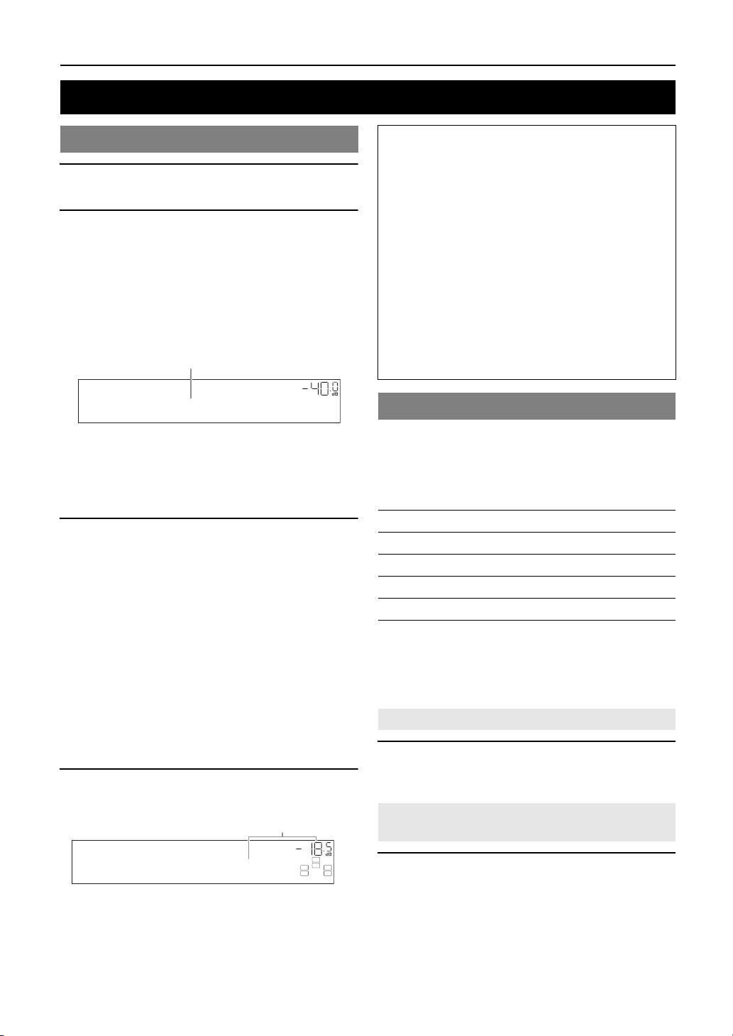
BASIC OPERATION
Playback
Basic procedure
1 Turn o n e x t erna l c o mponents (TV, DVD
player, etc.) connected to this unit.
2 Rotate the TINPUT selector (or press
dInput selection key) to select an input
source.
If you press dUSB/NET on the remote control,
press xSub-input selection key to select a
sub-input source.
The name of the selected input source is displayed for
a few seconds.
Input source name
VOL.
AV1
y
• If you connect two video monitors to the HDMI OUT jacks of this
unit, press gHDMI OUT repeatedly to select the active video
monitor(s) (page 53).
• You can also select an input source from the GUI screen (page 25).
• You can change the input source name displayed on the front panel
display or GUI screen as necessary (page 64).
3 Play the external component that you have
selected as the source input, or select a radio
station on the tuner.
Refer to the operating instructions of the external
component for details on playback. For selecting
radio stations or playback of an iPod, Bluetooth
component, USB storage device or network contents
using this unit, see the following.
• FM/AM radio tuning (page 31)
• iPod playback (page 44)
• Bluetooth component playback (page 46)
• USB storage device playback (page 47)
• Internet Radio playback (page 50)
• PC playback (page 48)
• Rhapsody
4 Turn t h e KVOLUME control (or press
tVOLUME +/–) to adjust the volume.
Volume-18.5dB
®
playback (page 51)
Vol um e
VOL.
SW
C
LR
SL SR
Note
When you play back a DTS-CD, noise may be output in some
conditions, which may cause a speaker malfunction. Make sure
that the volume is set to low before starting playback. If noise is
output, do the following.
1) When only noise is output
If a DTS bitstream signal is not properly input to this unit,
only noise is output. Connect the playback component to this
unit by digital connection and play back the DTS-CD. If the
condition is not improved, the problem may results from the
playback component. Consult the manufacturer of the
playback component.
2) When noise is output during playback or skip operation
Before playing back the DTS-CD, display the Option menu
after selecting the input source and set “Decoder Mode” to
“DTS” (page 54).
Using the SCENE function
This unit has a SCENE function that allows you to change
input sources and sound field programs with one key. Four
scenes are available for different usages, such as playing
movies or music. The following input sources and sound
field programs are provided as the initial factory settings.
Keys Input source Sound field program
BD/DVD HDMI 1 Straight
TV AV 1 Straight
CD AV 3 Straight
RADIO TUNER 7ch Enhancer
y
• When this unit is on standby, you can turn on this unit by pressing
RSCENE (or hSCENE).
• If you connect a Yamaha DVD/CD player that has the capability of the
SCENE control signals to the REMOTE OUT jack of this unit, you can
start playback on the player by using the SCENE function.
Selecting a SCENE
Press RSCENE (or hSCENE).
y
• You can also select a SCENE from the GUI screen (page 25).
Registering input source/sound field
program to SCENE
Select the desired input source/sound field
program and then press and hold RSCENE (or
hSCENE) to edit until “SET Complete” appears
on the front panel display.
y
• If you change the input source setting, register the remote control code of
an external component to the input source (page 72).
24 En
Page 29
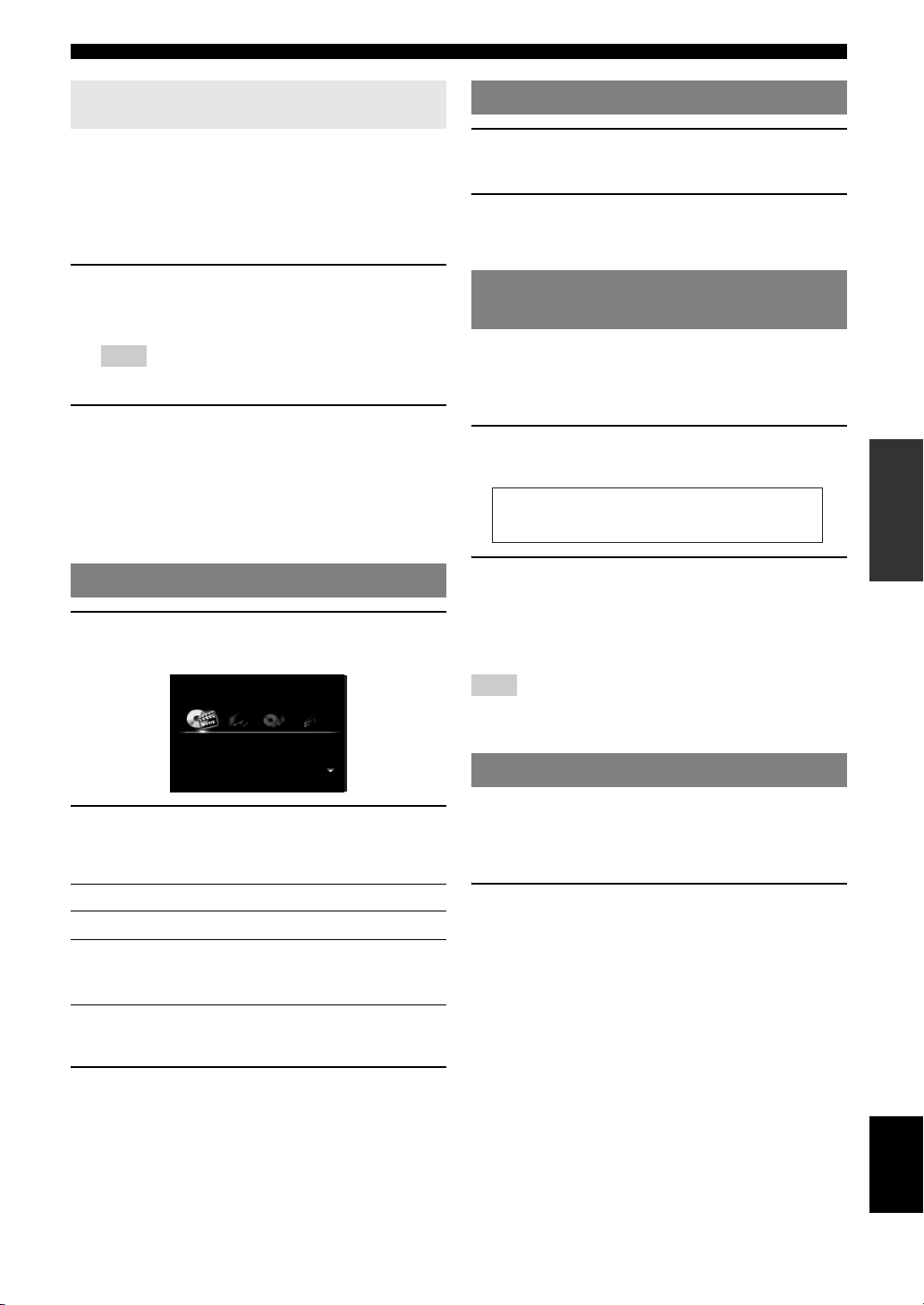
Playback
Switching remotely controlled external
components linked to scene selections
You can operate an external component with the remote
control of this unit by setting a remote control code for the
external component for each input source. Setting remote
control codes for desired input sources allows you to
switch between external components linked to scene
selections.
1 Register the remote control code of an
external component to the desired input
source (page 72).
Note
• This feature is not available for TUNER, SIRIUS and XM input
sources.
2 While holding down the desired hSCENE
key, press and hold the dInput selection
key to which you registered a remote control
code in step 1.
From now on the external component can be remotely
controllable just by selecting a scene.
Selecting a source on the GUI screen
1 Press iON SCREEN on the remote control.
The GUI screen appears on the video monitor.
Select Scene
BD/DVD TV CD RADIO
Muting audio output
1 Press vMUTE on the remote control to mute
the audio output.
2 Press vMUTE again to resume audio
output.
Adjusting high/low frequency sounds (tone control)
You can adjust the balance of the high frequency range
(Treble) and low frequency range (Bass) of sounds output
from the front left and right speakers to obtain desired
tone.
1 Press OTONE CONTROL on the front panel
repeatedly to select “Treble” or “Bass”.
Treble
0.0dB
2 Rotate the PPROGRAM selector to adjust
the frequency range.
Control range: –10.0 dB to +10.0 dB
The display returns to the previous screen
automatically in few seconds.
Note
• The tone control settings are not effective when this unit is in the Pure
Direct mode or “MULTI CH” is selected as an input source.
Enjoying pure hi-fi sound
INTRODUCTION
PREPARATION
OPERATION
BASIC
OPERATION
ADVANCED
INFORMATION APPENDIX
ADDITIONAL
2 Use jCursor k / n repeatedly to switch the
page and jCursor l / h repeatedly to
select the desired source.
Category Source
Select Scene BD/DVD, TV, CD, RADIO
Select Input HDMI1-4, V-AUX, PHONO, MULTI CH,
DOCK, AV1-6, AUDIO1/2, USB, NET
RADIO, PC, Rhapsody, TUNER, SIRIUS, XM
y
• If an input source you want to select is available in “Select Scene”, you
can select the desired input source and sound field program at once.
3 Press jENTER.
Use Pure Direct mode to enjoy the pure high fidelity
sound of the selected source. When Pure Direct mode is
activated, this unit plays back the selected source with the
least circuitry.
Press SPURE DIRECT (or rPURE DIRECT)
to turn the Pure Direct mode on or off.
SPURE DIRECT lights up when you set Pure Direct
mode on.
The following features are disabled in the Pure Direct
mode.
– sound field program, tone control
– display and operation of the Option menu and Setup
menu
– multi-zone function
y
• The font panel display automatically turns off while this unit in the Pure
Direct mode.
25 En
English
Page 30
Playback
Using your headphones
Plug your headphones in the MPHONES jack on
the front panel.
When you select a sound field program while using the
headphones, the mode is automatically set to SILENT
CINEMA mode.
Notes
• When you connect headphones, no signals are output at the speaker
terminals.
• When multi-channel signals are processed, sounds in all channels are
divided to left and right channels. When “MULTI CH” is selected as the
input source, only front L/R sounds are output from the headphones.
Changing information on the front panel display
Press EINFO (or fINFO) repeatedly.
Available information differs depending on the selected
input source.
For example, if you select HDMI1 input and display “DSP
Program”, the following screen appears on the front panel
display.
Input source
Input source Information
iPod (DOCK) (menu
browse mode)
USB (USB/NET)
PC (USB/NET)
Rhapsody (USB/NET) (on play information screen)
NET RADIO (USB/NET) (on play information display)
(on play information display)
DSP Program, Audio Decoder,
Song, Artist, Album
(on GUI screen)
List
DSP Program, Audio Decoder,
Song, Artist (or Artist / Channel if
channel name is available), Album
(on GUI screen)
List
DSP Program, Audio Decoder,
Station Name
(on GUI screen)
List
Note
• Information marked with “*” is not available when analog HD Radio
station is selected.
Straight
Sound field program
Input source Information
HDMI1-4
AV1 -6
AUDIO1/2
V-A UX
PHONO
iPod (DOCK) (simple
remote mode)
BLUETOOTH (DOCK)
MULTI CH Input
TUNER Frequency, DSP Program, Audio
SIRIUS Channel, Category, Artist / Song,
XM Channel, Category, Artist / Song,
Input
DSP Program
Audio Decoder
Decoder
(for HD Radio information)
Call Sign*, Category*, Artist /
Song*, Album*, Tag Info, DSP
Program, Audio Decoder, Frequency
Composer, Antenna, DSP Program,
Audio Decoder
Antenna, DSP Program, Audio
Decoder
26 En
Page 31

Enjoying the sound field programs
This unit is also equipped with a Yamaha digital sound field processing (DSP) chip. You can enjoy multi-channel sounds
for almost all input sources using various sound field programs stored on the chip and a variety of surround decoders.
Selecting sound field programs
■ Selecting a sound field program on the front panel
Rotate the PPROGRAM selector to select a desired sound field program.
■ Selecting a sound field program with the remote control
Perform the following operations depending on the category of the sound field programs.
Sound field programs for movies/TV programs............................... Press rMOVIE repeatedly.
Sound field programs for music....................................................... Press rMUSIC repeatedly.
Stereo reproduction .......................................................................... Press rSTEREO repeatedly.
Multi-channel stereo reproduction ................................................... Press rSTEREO repeatedly.
Compressed music enhancer ............................................................ Press rSTEREO repeatedly.
Surround decoder ............................................................................. Press rSUR.DECODE repeatedly.
For example, if you select “Sci-Fi”, the following screen appears on the front panel display.
INTRODUCTION
PREPARATION
Sound field program category
Sci-Fi
Program name
Notes
• Sound field programs are stored for each input source. When you change the input source, the sound field program previously selected for that input
source is applied again.
• When you play back DTS Express sources or audio signals with sampling frequency of higher than 96 kHz, the straight decode mode (page 30) is
automatically selected.
• When you play back Dolby TrueHD sources with CINEMA DSP, another program may be automatically selected in specific cases.
• When you play back DTS-HD sources with CINEMA DSP, the DTS decoder is automatically selected.
Sound field program descriptions
This unit provides sound field programs for multiple categories including music, movies and stereo reproduction. Select
a sound field program based on your listening preference, not merely on the name of the program, etc.
y
• You can check what speakers are currently outputting signals with the speaker indicators on the front panel display (page 6).
• Each program can adjust sound field elements (sound field parameters). For details, see page 65.
• in the table indicates the sound field program with CINEMA DSP (page 91).
For movie/TV program sources (MOVIE)
Program Descriptions
Standard This program creates a sound field emphasizing the surrounding feeling without disturbing the original acoustic
positioning of multi-channel audio such as Dolby Digital and DTS. It has been designed with the concept of “an
ideal movie theater”, in which the audience is surrounded by beautiful reverberations from the left, right and rear.
Spectacle This program represents the spectacular feeling of large-scale movie productions.
It reproduces a broad theater sound field matching the cinemascope and wider-screen movies with an excellent
dynamic range from very small to extremely large sound.
Sci-Fi This program clearly reproduces the finely elaborated sound design of the latest science fiction and special effects-
featuring movies. You can enjoy a variety of cinematographically created virtual spaces reproduced with clear
separation between dialog, sound effects and background music.
Adventure This program is ideal for precisely reproducing the sound design of action and adventure movies.
The sound field restrains reverberations but puts emphasis on reproducing a powerful space expanded widely to
the left and right. The reproduced depth is also restrained relatively to ensure the separation between audio
channels and the clarity of the sound.
OPERATION
BASIC
OPERATION
ADVANCED
INFORMATION APPENDIX
ADDITIONAL
English
27 En
Page 32

Enjoying the sound field programs
Program Descriptions
Drama This sound field features stable reverberations that match a wide range of movie genres from serious dramas to
musicals and comedies. The reverberations are modest but offer an optimum 3D feeling, reproducing effects tones
and background music softly but cubically around clear words and center positioning in a way that does not fatigue
the listener even after long hours of viewing.
Mono Movie This program is provided for reproducing monaural video sources such as a classic movie in an atmosphere of a
good old movie theater. The program produces the optimum expansion and reverberation to the original audio to
create a comfortable space with a certain sound depth.
Sports This program allows the listeners to enjoy stereo sport broadcasts and studio variety programs with enriched live
feeling. In sports broadcasts, the voices of the commentator and sportscaster are positioned clearly at the center
while the atmosphere of the stadium expands in an optimum space to offer the listeners with a feeling of presence
in the stadium.
Action Game This sound field has been suitable for action games such as car racing and FPS games. It uses the reflection data
that limits the effects range per channel in order to offer a powerful playing environment with a being-there feeling
by enhancing various effects tones while maintaining a clear sense of directions.
Roleplaying Game This sound field has been suitable for role-playing and adventure games. It combines the sound field effects for
movies and the sound field designs for “Action Game” to represent the depth and 3D feeling of the field during
play, while offering movie-like surround effects in the movie scenes in the game.
For audio music sources (MUSIC)
Program Descriptions
Hall in Munich This sound field simulates a concert hall with approximately 2500 seats in Munich, using stylish wood for the
interior finishing as normal standards for European concert halls. Fine, beautiful reverberations spread richly,
creating a calming atmosphere. The listener’s virtual seat is at the center left of the arena.
Hall in Vienna This is an approximately 1700-seated, middle-sized concert hall with a shoebox shape that is traditional in Vienna.
Pillars and ornate carvings create extremely complex reflections from all around the audience, producing a very
full, rich sound.
Chamber This program creates a relatively wide space with a high ceiling like an audience hall in a palace. It offers pleasant
reverberations that are suitable for courtly music and chamber music.
Cellar Club This program simulates a live house with a low ceiling and homey atmosphere. A realistic, live sound field
features powerful sound as if the listener is in a row in front of a small stage.
The Roxy Theatre This is the sound field of a rock music live house in Los Angeles, with approximately 460 seats. The listener’s
virtual seat is at the center left of the hall.
The Bottom Line This is the sound field at stage front in The Bottom Line, that was a famous New York jazz club once. The floor
can seat 300 people to the left and right in a sound field offering real and vibrant sound.
Music Video This sound field offers an image of a concert hall for live performance of pop, rock and jazz music. The listener
can indulge oneself in a hot live space thanks to the presence sound field that emphasizes the vividness of vocals
and solo play and the beat of rhythm instruments, and to the surround sound field that reproduces the space of a
big live hall.
For stereo reproduction (STEREO)
Program Descriptions
2ch Stereo Use this program to mix down multi-channel sources to 2 channels.
y
• When multi-channel signals are input, they are downmixed to 2 channels and output from the front left and right speakers.
28 En
Page 33

For multi-channel stereo reproduction (STEREO)
Enjoying the sound field programs
Program Descriptions
7ch Stereo Use this program to output sound from all speakers. When you play back multi-channel sources, this unit
downmixes the source to 2 channels and then outputs the sound from all speakers. This program creates a larger
sound field and is ideal for background music at parties, etc.
Compressed Music Enhancer (ENHANCER)
Program Descriptions
Straight Enhancer Use this program to enhance the sound nearest to the original depth and width of the 2-channel or multi-channel
compression artifacts.
7ch Enhancer Use this program to play back compression artifacts in 7-channel stereo.
Surround decode mode (SUR. DECODE)
Select this program to playback sources with selected decoders. You can playback 2-channel sources on multi-channels.
Decoder Descriptions
Pro Logic Dolby Pro Logic decoder suitable for all kinds of sources.
PLIIx Movie /
PLII Movie
PLIIx Music /
PLII Music
PLIIx Game /
PLII Game
Neo:6 Cinema DTS decoder suitable for movies.
Neo:6 Music DTS decoder suitable for music.
Neural Sur.
(U.S.A. model only)
Dolby Pro Logic IIx (or Dolby Pro Logic II) decoder suitable for movies. If your listening environment is as
follows, you cannot select the Dolby Pro Logic IIx decoder.
• When the surround back speakers are not connected
• When headphones are connected
Dolby Pro Logic IIx (or Dolby Pro Logic II) decoder suitable for music. If your listening environment is as
follows, you cannot select the Dolby Pro Logic IIx decoder.
• When the surround back speakers are not connected
• When headphones are connected
Dolby Pro Logic IIx (or Dolby Pro Logic II) decoder suitable for games. If your listening environment is as
follows, you cannot select the Dolby Pro Logic IIx decoder.
• When the surround back speakers are not connected
• When headphones are connected
Neural Surround processing for any sources.
The Neural Surround decoder supports PCM (sampling rate of 96 kHz or lower), Dolby Digital, DTS Digital
Surround (except for DTS 96/24), DSD and analog 2-channel input sources. When Neural Surround-incompatible
signals are being input while the Neural Surround decoder is selected, multi-channel sources are decoded straight
into the appropriate channels without any additional effect processing and the Neural Surround-incompatible PCM
signals are reproduced in stereo. The Neural Surround decoder is especially suitable for the XM HD Surround
program of XM Satellite Radio.
INTRODUCTION
PREPARATION
OPERATION
BASIC
OPERATION
ADVANCED
INFORMATION APPENDIX
ADDITIONAL
y
• An input source is played back in straight decode mode (page 30) when “MULTI CH” is selected as the input source.
English
29 En
Page 34

Enjoying the sound field programs
Enjoying unprocessed input sources (Straight decode mode)
In straight decode mode, sounds are reproduced without
sound field effect. 2-channel stereo sources are output
from only the front left and right speakers. Multi-channel
input sources are decoded straight into the appropriate
channels and multi-channel sounds are reproduced
without a sound field effect.
1 To enable straight decode mode, press
QSTRAIGHT (or rSTRAIGHT).
“Straight” appears on the front panel display.
2 To cancel straight decode mode, press
QSTRAIGHT (or rSTRAIGHT) again.
A sound field program name appears on the front
panel display, and sound is reproduced with that
sound field effect.
Enjoying sound field programs without surround speakers (Virtual CINEMA DSP)
Virtual CINEMA DSP allows you to enjoy DSP sound
field surround effects even without any surround speakers
by using virtual surround speakers. You can even enjoy
Virtual CINEMA DSP using a minimal two-speaker
system that does not include a center speaker.
When “Surround Speaker” in the Setup menu is set to
“None” (page 60), this unit operates in Virtual CINEMA
DSP mode.
Enjoy sound field programs with headphones (SILENT CINEMA™)
SILENT CINEMA allows you to enjoy multi-channel
sources with your headphones. SILENT CINEMA mode
is automatically selected when you connect the headphone
plug to the PHONES jack.
Note
• SILENT CINEMA mode is not available in the following conditions.
– 2ch Stereo of the sound field program is selected.
– Pure Direct mode or straight decode mode is selected.
Using CINEMA DSP 3D mode
CINEMA DSP 3D mode creates the intensive and
accurate stereoscopic sound field in the listening room.
To use this unit in CINEMA DSP 3D mode, presence
speakers are required. Connect the presence speakers to
the SP1 terminals, perform the following settings and then
select a CINEMA DSP related sound field program.
• Disconnect the headphones from the PHONES jack.
• Set “Extra Speaker Assignment” to “Presence”
(page 60).
• Set “3D DSP” to “On” (page 66).
When the sound field program runs in CINEMA DSP 3D
mode, the 3D indicator on the front panel display lights
up.
Note
• Virtual CINEMA DSP is not available in the following conditions even if
you set “Surround Speaker” to “None” (page 60).
– headphone plug is connected to the PHONES jack.
– 7ch Stereo of the field sound program is selected.
– Pure Direct mode or straight decode mode is used.
30 En
Page 35

FM/AM tuning
The FM/AM tuner of this unit provides the following two
modes for tuning.
■ Frequency tuning mode
You can tune in to a desired FM/AM station by searching
or specifying its frequency.
■ Preset tuning mode
You can preset the frequencies of FM/AM stations by
registering them to specific numbers, and later just select
those numbers to tune in.
Note
• Adjust the FM/AM antennas connected to this unit for the best reception.
Tuning in to the desired FM/AM station (Frequency tuning)
1 Rotate the TINPUT selector (or press
dTUNER) to select “TUNER” as the input
source.
2 Press HBAND (or eFM or eAM) to select a
band.
3 Press ITUNING/CH l / h (or eTUN./CH
k / n) to specify the frequency.
The TUNED indicator on the front panel display
lights up when the tuner is tuned in to a station. The
STEREO indicator also lights up if the program being
broadcasted is in stereo.
STEREO
TUNED
FM92.5MHz
The frequency changes in the following manner according
to how you press ITUNING/CH l / h (or eTUN./
CH k / n).
When you press the key more than 1 second
The tuner searches the frequency of a station that is
detectable around the current frequency. This is effective
when the tuner can receive strong signals without any
interference. Once the search starts, release the key.
When you keep holding the key, the search continues even
when a station is detected. This is useful when you want to
tune in to a specific station.
When you press and release the key
The tuner increases or decreases the frequency in steps.
Use this method when the tuner cannot receive strong
signals and stations are skipped during the search.
y
• You can switch between stereo and monaural for FM broadcast in the
Option menu (page 55).
• (U.S.A. model only)
When tuning in to an HD Radio station, the HD indicator lights up. See
page 33 for details about the HD Radio features.
4 To tune in by direct frequency tuning, press
lNumeric keys to enter the frequency of
the station.
Enter only integers. For example, if you want to set
the frequency to 88.9 MHz, enter “889”.
Notes
• When you press lNumeric keys during preset tuning, a
preset number is selected. Set tuning mode to frequency tuning
mode using ITUNING/CH l / h (or eTUN./CH k / n)
prior to the operation.
• “Wrong Station!” appears on the front panel display when you
enter a frequency that is out of receivable range. Make sure that the
entered frequency is correct.
Registering FM/AM stations and tuning in (Preset tuning)
You can register up to 40 FM/AM stations (Preset).
Registering stations by automatic station
preset
The tuner automatically detects FM stations with strong
signals and registers up to 40 stations. To register AM
stations, use manual station preset.
(U.S.A. model only)
You can register up to 40 FM HD Radio, AM HD Radio
and analog FM radio stations with strong signals.
Note
• (U.S.A. model only)
If you register an FM HD Radio station with this feature, only the main
audio program of the station (HD1) will be stored. To store other audio
program, preset the station manually.
1 Rotate the TINPUT selector (or press
dTUNER) to select “TUNER” as the input
source.
2 Press sOPTION on the remote control.
The Option menu for “TUNER” is displayed
(page 54).
3 Select “Auto Preset” and then press
jENTER.
Auto Preset
Automatic station preset starts about 5 seconds later
from the lowest frequency upwards.
INTRODUCTION
PREPARATION
OPERATION
BASIC
OPERATION
ADVANCED
INFORMATION APPENDIX
ADDITIONAL
English
31 En
Page 36

FM/AM tuning
y
• You can select the preset number at which the preset starts by
pressing ePRESET k / n or jCursor k / n while “READY”
is displayed on the front panel display.
• To cancel registration, press jRETURN.
Status
01:FM87.5MHz
Preset number Frequency
During the automatic station preset, “MEMORY”
appears in the front panel display each time a station
is registered.
When registration is complete, “FINISH” appears
and then the display returns to the Option menu.
To return the display to the original state, press
sOPTION.
Registering stations by manual station
preset
You can manually register FM stations with weak signals
or AM stations.
1 Tune in to the desired station (page 31).
y
• (U.S.A. model only)
To register a sub-audio program of the HD Radio station (HD2 to
HD8), press wPRG SELECT to select the desired audio
program.
2 Press GMEMORY (or eMEMORY).
“Manual Preset” appears on the front panel display,
followed soon by the preset number to which the
station will be registered.
y
• By holding down GMEMORY (or eMEMORY) for more than
2 seconds, you can skip the following steps and automatically
register the selected station to an empty preset number (next to the
lastly-registered preset number).
4 Press GMEMORY (or eMEMORY).
When registration is complete, the display returns to
the original state.
y
• To cancel registration, press jRETURN or leave this unit
without any operations for about 30 seconds.
Calling a preset station (Preset tuning)
You can call preset stations registered by automatic station
preset or manual station preset.
Press FPRESET l / h (or ePRESET k / n) to
select a preset number.
y
• Preset numbers to which no stations are registered are skipped.
• “No Presets” or “No Presets in Memory” is displayed if no stations are
registered.
• You can directly select a preset number by pressing lNumeric keys
while calling a preset station. “Empty” appears on the display if you
enter a preset number to which no station is registered. “Wrong Num.”
appears if you enter an invalid number.
• When you press lNumeric keys during normal tuning, a frequency
is entered. Set tuning mode to preset tuning mode using FPRESET l
/ h (or ePRESET k / n) prior to the operation.
• (U.S.A. model only)
This unit may take a little time to call a sub-audio program of an HD
Radio station.
Clearing preset stations
1 Rotate the TINPUT selector (or press
dTUNER) to select “TUNER” as the input
source.
2 Press sOPTION on the remote control.
The Option menu for “TUNER” is displayed
(page 54).
3 Press jCursor k / n to select “Clear Preset”
and then press jENTER.
3 Press FPRESET l / h (or ePRESET k / n)
to select the preset number to which the
station will be registered.
When you select a preset number to which no station
is registered, “Empty” appears. When you select a
preset number to which any station has been already
registered, the frequency of the station is displayed.
Frequency to be registered
01:Empty
Preset
number
32 En
Flashes
y
• You can also select a preset number using the lNumeric
keys.
01:FM92.5MHz
Preset number
y
• To cancel the operation and return to the Option menu, press
jRETURN.
4 Press jCursor k / n to select a preset
number to reset and then press jENTER.
The preset station registered to the selected preset
number is cleared. To clear the registration of
multiple preset numbers, repeat step 4.
5 To exit the Option menu, press sOPTION.
Page 37

Using HD Radio™ features (U.S.A. model only)
HD Radio technology is a new technology that enables FM and AM radio stations to broadcast programs digitally.
Digital broadcasting provides listeners with radically improved audio quality and reception as well as new data services.
Furthermore, supplemental program services allow listeners to select from up to 8 HD Radio programs multicast on a
single FM HD Radio channel. For further information on HD Radio technology, visit “http://www.hdradio.com/”.
This unit is equipped with an HD Radio reception feature, facilitating CD quality FM broadcasts as well as analog FM
stereo quality AM broadcasts. In addition, this unit can receive both audio and data (such as song titles, artist names,
program types, and comments) from all HD Radio programs (HD1 to HD8).
Notes
• The tuning method for HD Radio stations are same as analog FM/AM radio stations; however, you only tune into the analog part of a hybrid HD Radio
station while this unit is in the monaural tuning mode (page 55).
• This unit is capable of receiving both hybrid and all-digital HD Radio station signals. However, this unit may not automatically receive all-digital FM
station signals and the automatic tuning operation may stop. In this case, enter the frequency of the desired all-digital FM HD Radio station directly by
using the lNumeric keys (page 31).
INTRODUCTION
PREPARATION
Selecting HD Radio™ audio programs
The HD indicator lights up in the front panel display when
this unit is tuned into an HD Radio reception band. In this
state, you can select the desired audio program if the
selected FM HD Radio station provides multiple audio
programs (up to 8).
■ When multiple audio programs are provided
Audio program
number (relative/total)
FM 88.9MHz1
Press wPRG SELECT b / a on the remote
control repeatedly to select the desired audio
program.
y
• You can also select audio program using lNumeric keys(1-8) and
lENT when this unit is in the automatic or manual tuning mode. In
case you select an audio program currently not available, “HDx Off” (“x”
indicates the program number) appears.
Notes
• When reception for an audio program ceases, the HD indicator
disappears from the front panel display and HD1 is automatically
selected after approximately 20 seconds.
• Some audio programs may not contain data programs depending on the
broadcasting station and the time period.
■ When only one audio program is provided
If this unit is tuned into an FM HD Radio station including
only one audio program or an AM HD Radio station, you
cannot select audio programs.
FM 87.5MHz
Lights up
HD
Lights up
HD
Audio program
number (absolute)
■ Behavior of the display
This unit automatically shows the HD Radio information
(call sign, etc) on the front panel display after 3 seconds.
You can switch HD Radio information to be displayed
(page 34).
HD
WXYZ-FM
Using the iTunes Tagging feature
This unit is equipped with the iTunes Tagging feature that
enables HD Radio listeners to “tag” songs for subsequent
preview and purchase on iTunes. For details on the iTunes
Tagging feature, visit “http://www.hdradio.com/”.
1 Tune into an HD Radio station and select HD
Radio audio program (if available).
If the selected HD Radio program (or song being
played) supports the iTunes Tagging feature, the TAG
indicator lights up in the front panel display and
“TAG” appears on the GUI screen.
Lights up
HD
TAG
TUNED
WXYZ-FM
2 While a song you want to tag is being played
back, press wTAG on the remote control.
If a song is tagged, “StorageSuccess” and the number
of stored iTunes Tagging information files (up to 50)
appear in the front panel display.
Notes
• “Insufficient Data’ appears in the front panel display and GUI
screen if tagging is not available.
• If a status message or an error message appears on the front panel
display or the GUI screen, see “iTunes Tagging” (page 80).
OPERATION
BASIC
OPERATION
ADVANCED
INFORMATION APPENDIX
ADDITIONAL
English
33 En
Page 38

Using HD Radio™ features (U.S.A. model only)
y
• This unit transmits the “tag” data to the iPod if an iPod that
supports iTunes Tagging feature is stationed in the Yamaha iPod
universal dock (YDS-11, sold separately) connected to the DOCK
terminal of this unit. Otherwise, this unit stores the “tag” data (up
to 50) in the internal memory and will transmit it next time your
iPod is stationed.
Displaying HD Radio™ information
Audio Decoder
Current audio decoder (page 29), frequency, audio
program number (absolute)
Use this feature to display the HD Radio information in
the front panel display or on the GUI screen.
Note
• If a status message or an error message appears on the front panel display
or GUI screen, see “HD Radio Reception” (page 79).
■ Front panel display
Press EINFO
(or fINFO
) repeatedly to toggle the
following HD Radio information display modes.
Call Sign
Call sign, frequency, audio program number (absolute)
Category
Program category, frequency, audio program number
(absolute)
Artist / Song
Artist name, song title, frequency, audio program
number (absolute)
Album
Album title, frequency, audio program number
(absolute)
Tag Info
The number of iTunes Tagging information files stored
in the internal memory, frequency, audio program
number (absolute)
DSP Program
Current sound field program (page 27), frequency, audio
program number (absolute)
Frequency
Frequency, audio program number (absolute), audio
program number (relative/total)
Back to “Call Sign”
Display example (Call Sign)
HD
WXYZ-FM
■ GUI screen
Press uDISPLAY on the remote control to turn
on or off the information display.
The following information is displayed on the GUI screen.
STEREO
d
TAG
e
Preset no.10:
Ch Name
Category
Artist
Song
WXYZ-FM HD 1/3
Classic Rock
Frankie Zipper
Road to India
Made-to-order
FM 88.9MHz-1
Option Menu
Data Hold
f
g
a
b
TUNED
c
Input
Tuner
DSP
Straight Enhancer
a Preset number, call sign, audio program number
(relative/total)
b HD Radio icon, TUNED icon
c Program category, artist name, song title, album
title
d STEREO icon
e TAG ico n
f Frequency indication gauge
g Band, frequency, audio program
y
• To hold or release the displayed information, press jENTER. While it
is held, the “HOLD” icon appears on the GUI screen.
34 En
Page 39

XM® Satellite Radio tuning (U.S.A. model only)
K
O
COMPO
T
O
OUT
o
(
H
OL
)
S
Listening to Satellite Radio
To listen to Satellite Radio, you’ll need to connect either a SIRIUS or XM Satellite Radio tuner (sold separately) to your
satellite-ready receiver. Satellite Radio is available to residents of the US (except Alaska and Hawaii).
Satellite Radio delivers a variety of commercial-free music from categories ranging from Pop, Rock, Country, R&B,
Dance, Jazz, Classical and many more plus coverage of all the top professional and college sports including play by play
games from select leagues and teams. Additional programming includes expert sports talk, uncensored entertainment,
comedy, family programming, local traffic and weather and news from your most trusted sources.
Whether you purchase a SIRIUS or XM tuner, you’ll need to activate and subscribe to begin enjoying the service. Easy to
follow installation and setup instructions are provided with the satellite tuners. Whichever service you choose, there are a
variety of programming packages available, including the option of adding “The Best of SIRIUS” programming to your
XM tuner or “The Best of XM” programming to your SIRIUS tuner, enabling you to enjoy the most popular
programming among both services. The “Best of” packages are not available to SIRIUS or XM Canada subscribers at
this time. Family friendly packages are also available to restrict channels featuring content that may be inappropriate for
children.
To subscribe to XM, U.S. customers should visit xmradio.com or call 1-800-XMRADIO (1-800-967-2346).
To subscribe to SIRIUS, U.S. customers can call 1-888-539-SIRI (1-888-539-7474) or visit sirius.com (US).
SIRIUS XM Radio Legal
SIRIUS, XM and all related marks and logos are trademarks of Sirius XM Radio Inc. and its subsidiaries. All other
marks and logos are the property of their respective owners. All rights reserved. SIRIUS and XM subscriptions sold
separately. Taxes and a one-time activation fee may apply. XM tuners and home docks or SIRIUS tuners (each sold
separately) are required to receive the SIRIUS or XM satellite radio service. All programming and fees subject to
change. It is prohibited to copy, decompile, disassemble, reverse engineer, hack, manipulate or otherwise make
available any technology or software incorporated in receivers compatible with the SIRIUS or XM Satellite Radio
Systems. Service not available in Alaska and Hawaii.
INTRODUCTION
PREPARATION
OPERATION
BASIC
OPERATION
ADVANCED
Connecting XM Mini-Tuner Home Dock
Connect XM Mini-Tuner and XM Mini-Tuner Home
Dock (sold separately) to the XM jack on the rear panel of
this unit. For details, see the operating instructions
provided with the XM Mini-Tuner Home Dock.
PHON
IRIUS
OC
NEN
VIDE
XM Mini-Tuner and XM Mini-Tuner Home Dock
(sold separately)
y
• To ensure optimal reception of the XM Satellite Radio signals, the XM
Mini-Tuner Home Dock must be placed at or near a southerly facing
window with no obstacles in the path to the sky. You can mount it indoors
or outdoors. Use the “Antenna” information on the front panel display or
on the GUI screen (page 38) to check the antenna reception level and
adjust the orientation of the antenna.
HD Radi
HDMI OUT
DMI CONTR
Note
• If “CHECK ANTENNA”, “CHECK XM TUNER” or “NO SIGNAL”
appears on the front panel display, the connection and setting of the
antenna, XM Mini-Tuner Home Dock, or XM Mini-Tuner may not be
correct.
Activating XM Satellite Radio
Once you have installed the XM Mini-Tuner Home Dock,
inserted the XM Mini-Tuner, connected the XM MiniTuner Home Dock to your XM Ready® home audio
system, and installed the antenna, you are ready to
subscribe and begin receiving XM programming. There
are three places to find your eight character XM Radio ID:
on the XM Mini-Tuner, on the XM Mini-Tuner package,
and on XM Channel 0. Record the XM Radio ID in the
following eight squares for reference.
Note
• The XM Radio ID does not use the letters “I”, “O”, “S” or “F”. Activate
your XM Satellite Radio service in the U.S. online at http://
activate.xmradio.com/ or call 1-800-XM-RADIO (1-800-967-2346). You
will need a major credit card. XM will send a signal from the satellites to
activate the full channel lineup. Activation normally takes 10 to 15
minutes, but during peak busy periods you may need to keep your XM
Ready home audio system on for up to an hour. When you can access the
full lineup on your XM Ready home audio system you are done.
INFORMATION APPENDIX
ADDITIONAL
English
35 En
Page 40

XM® Satellite Radio tuning (U.S.A. model only)
XM Satellite Radio® operations
1 Rotate the TINPUT selector (or press
dXM) to select “XM” as the input source.
The XM Satellite Radio information (such as channel
number, channel name, category, artist name, or song
title) for the currently selected channel appears on the
front panel display and GUI screen (page 38).
Search mode
XM
001Preview
Channel number Channel name
y
• When you select “XM” as the input source, this unit automatically
recalls the previously selected channel.
Note
• If a status message or an error message appears on the front panel
display or on the GUI screen, see “XM Satellite Radio” (page 80).
2 Search for a channel by using one of the XM
Satellite Radio search modes.
• To select a channel from the all channel list, see
“All Channel Search mode” on this page.
• To select a channel by category, see “Category
Search mode” on this page.
• To select the desired channel directly by entering
the channel number, see “Direct number access” on
this page.
• To select a channel from the preset channels, see
“Calling a preset channel (Preset Search mode)”
(page 37).
y
• You can display the XM Satellite Radio information on the front
panel display or on the GUI screen (page 38).
• You can set the XM Satellite Radio preset channels (page 37).
■ All Channel Search mode
Press ITUNING/CH l / h (or eTUN./CH k /
n) repeatedly to search for a channel within all
channels.
XM
00880's
y
• You can search for a channel quickly by holding down
ITUNING/CH l / h (or eTUN./CH k / n).
• You can skip channels to the previous or next category by pressing
HCATEGORY (or eCATEGORY l / h).
■ Category Search mode
1 Press HCATEGORY (or eCATEGORY l /
h) to select the channel category.
“CAT” is displayed on the front panel display during
the channel category selection. When you select the
category, the first channel in the category is selected.
Category
search mode
XM
The first channel in the category
Pop
Category name
Note
• If you do not operate within 10 seconds, the category search mode
returns to “ALL” (All Channel Search).
2 While “CAT” is displayed on the front panel
display, press ITUNING/CH l / h (or
eTUN./CH k / n) repeatedly to search for a
channel within the selected channel
category.
y
• You can search for a channel quickly by pressing and holding
ITUNING/CH l / h (or eTUN./CH k / n).
Note
• This unit skips the channels when this unit is in the All Channel
Search mode or Category Search mode in the following cases (it is
not malfunction of this unit):
– the channel is out of service.
– you do not subscribe to the channel.
■ Direct number access
In the All Channel Search mode or Category
search mode, press the lNumeric keys to
enter the desired three-digit channel number.
For example, to enter the number 123, press the
lNumeric keys as “1”, “2” and “3”.
y
• To display the Radio ID number displayed on the front panel display,
select channel “0”.
• To enter a one-digit or two-digit channel number, press the lNumeric
keys on the remote control and then press lENT to confirm the input
number.
• Instead of pressing lENT to tune into the channel immediately, you
can wait a few seconds until this unit confirms the entered channel
number.
• If no key is pressed within a few seconds after you enter a one-digit or
two-digit number, this unit automatically confirms the entered channel
number.
• If the selected channel is not available, an advisory message may appear.
For details, see “XM Satellite Radio” (page 80).
36 En
Page 41

XM® Satellite Radio tuning (U.S.A. model only)
Registering XM Satellite Radio channels
You can use this feature to store up to 40 XM Satellite
Radio channels. You can then recall any preset channel
easily by selecting the preset channel as described in
“Calling a preset channel (Preset Search mode)” on this
page.
Registering preset channels
1 Search a channel you want to set as a preset
channel in one of the XM Satellite Radio
search modes.
For details, see “XM Satellite Radio operations”
(page 36).
XM
00880's
2 Press GMEMORY (or eMEMORY).
The indicator on the front panel display changes as
follows.
Currently registered channel number
XM
(or “---” if empty)
P01:---<<008
Preset number to which new
channel number is registered
y
• By holding down GMEMORY (or eMEMORY) for more than
2 seconds, you can skip the following steps and automatically
register the selected channel to an empty preset number (next to the
lastly-registered preset number).
• To cancel the preset operation, press jRETURN.
3 Press FPRESET l / h (or ePRESET k / n)
to select the stored preset station number.
y
• You can also select a preset number using the lNumeric
keys.
• If you select a preset number being used (currently registered
channel number appears next to the preset number), the current
preset channel will be overwritten.
Channel number to be
registered
Calling a preset channel (Preset Search
mode)
Prior to selecting a preset channel in the Preset Search
mode, you must preset XM channels. For details, see
“Registering preset channels” on this page.
Preset channel number
XM
00880's
Press FPRESET l / h (or ePRESET k / n)
repeatedly to change the preset channel number
(1 to 40).
y
• You can directly select a preset number by pressing a lNumeric key
while calling a preset channel.
Clearing preset channels
You can clear the assignments of preset XM Satellite
Radio channels.
1 Press sOPTION on the remote control.
The Option menu for “XM” is displayed.
2 Press jCursor k / n repeatedly to select
“Clear Preset” and then press jENTER.
3 Press jCursor k / n to select the preset
station number that you want to clear.
XM
008 80's
4 Press jENTER to execute the clearing of
the selected preset channel.
To clear the registration of multiple preset numbers,
repeat steps 3 and 4.
5 To exit the Option menu, press sOPTION.
INTRODUCTION
PREPARATION
OPERATION
BASIC
OPERATION
ADVANCED
INFORMATION APPENDIX
ADDITIONAL
4 Press GMEMORY (or eMEMORY).
English
37 En
Page 42

XM® Satellite Radio tuning (U.S.A. model only)
Displaying the XM Satellite Radio™ information
Use this feature to display the XM Satellite Radio information
on the front panel display or on the GUI screen.
Note
• If a status message or an error message appears on the front panel display
or GUI screen, see “XM Satellite Radio” (page 80).
■ Front panel display
Press EINFO (or fINFO) repeatedly to toggle
the following XM Satellite Radio information
display modes.
Channel
Channel number, channel name
Category
Channel category, channel number
Artist / Song
■ GUI screen
Press uDISPLAY on the remote control to turn
on or off the information display.
The following information is displayed on the GUI screen.
d
All Channel Search
Ch Name
Category
Artist
Song
Ch 008
80’s
Decades
Sanumemo
Road to India
Option Menu
Hold Data
a
b
c
Input
XM
DSP
Straight Enhancer
a Channel number
b Search mode (page 36)
c Channel name, channel category, artist name,
song title
d Antenna reception level
y
• To hold or release the displayed information, press jENTER. While it
is held, the “HOLD” icon appears on the GUI screen.
Artist name, song title, channel number
Antenna
Antenna reception level, channel number
DSP Program
Current sound field program (page 27), channel number
Audio Decoder
Current audio decoder (page 29), channel number
Back to “Channel”
Display example (Antenna)
XM
Antenna
y
• You can configure the scroll setting of the front panel display with “Front
Panel Display Scroll” in the Setup menu (page 63).
• If the XM Satellite Radio information contains a character that cannot be
recognized by this unit, the character will be displayed with a space.
• When an information is unavailable, “––––” appears.
38 En
Page 43

SIRIUS Satellite Radio™ tuning (U.S.A. model only)
K
O
COMPO
OUT
Connecting the SiriusConnect™ tuner
Connect the SiriusConnect tuner (sold separately) to the
SIRIUS jack on the rear panel of this unit. For details, see
the operating instructions provided with the SiriusConnect
tuner.
SiriusConnect Tuner and the antenna
y
• To ensure optimal reception of the SIRIUS Satellite Radio signals, the
antenna of the SiriusConnect tuner must be placed at or near a window
with no obstacles in the path to the sky. The orientation of the antenna for
the best reception differs depending on the area. Refer to the instruction
manuals supplied with the SiriusConnect tuner for the installation of the
antenna. You can mount it indoors or outdoors.
• Use the “Antenna” information in the front panel or “SIRIUS
Information” screen on the GUI screen (page 43) to check the antenna
reception level and adjust the orientation of the antenna.
• You need to connect the SiriusConnect tuner to the AC wall outlet.
SIRIUS
(sold separately)
PHON
OC
NENT
VIDEO
T
N
A
V
5
C
D
To the AC wall outlet
Notes
• If “CHECK SR TUNER” or “ANTENNA ERROR” appears on the front
panel display, the connection of the SiriusConnect tuner or antenna is
incorrect. In such cases, check the connection of the SiriusConnect tuner
and the antenna.
• If “NOT SUPPORTED” appears on the front panel display, this unit does
not support the connected SiriusConnect tuner.
Activating SIRIUS Satellite Radio™ subscription
Before using the SIRIUS Satellite Radio feature, you need
to activate your SIRIUS Satellite Radio subscription. To
activate the subscription you need the Sirius ID which is
uniquely assigned to the SiriusConnect tuner. Sirius ID is
12-digit number and it appears on the package of the
SiriusConnect tuner, on the label of the SiriusConnect
tuner, and when you tune into the SIRIUS Satellite Radio
channel “0” (see below).
Displaying the Sirius ID of your
SiriusConnect tuner
1 Rotate the TINPUT selector (or press
dSIRIUS) to select “SIRIUS” as the input
source.
2 Press l0 and then lENT to display the
Sirius ID of your SiriusConnect tuner.
“000 Sirius ID” and “xxxxxxxxxxxx”
(“xxxxxxxxxxxx” indicates the 12-digit Sirius ID of
your SiriusConnect tuner) appears alternately on the
front panel display.
Write the Sirius ID below.
ID:________________________________________
3 Contact SIRIUS Satellite Radio to activate
your subscription.
SIRIUS Satellite Radio online information
Contact for activation
URL: https://activate.siriusradio.com/
Phone: 1-888-539-SIRIUS (1-888-539-7474)
y
• Status messages appear on the front panel display or GUI screen
during the activation. For details, see “SIRIUS Satellite Radio”
(page 81). Once the activation is finished, “SUB UPDATED”
appears.
SIRIUS Satellite Radio™ operations
1 Rotate the TINPUT selector (or press
dSIRIUS) to select “SIRIUS” as the input
source.
The SIRIUS indicator lights up on the front panel
display and the SIRIUS Satellite Radio information
(such as channel number, channel name, category,
artist name, or song title) for the currently selected
channel appears on the front panel display.
Search mode
SIRIUS
184Weather
INTRODUCTION
PREPARATION
OPERATION
BASIC
OPERATION
ADVANCED
INFORMATION APPENDIX
ADDITIONAL
Channel number Channel name
y
• When you select “SIRIUS” as the input source, this unit
automatically recalls the previously selected channel.
Notes
• When you have not activated your subscription yet, you can only
select “184” or “000”.
• If a status message or an error message appears on the front panel
display or on the GUI screen, see “SIRIUS Satellite Radio”
(page 81).
English
39 En
Page 44

SIRIUS Satellite Radio™ tuning (U.S.A. model only)
2 Search for a channel by using one of the
SIRIUS Satellite Radio search modes.
• To select a channel from the all channel list, see
“All Channel Search mode” on this page.
• To select a channel by category, see “Category
Search mode” on this page.
• To select the desired channel directly by entering
the channel number, see “Direct number access” on
this page.
• To select a channel from the preset channels, see
“Calling a preset channel (Preset Search mode)”
(page 41).
y
• You can display the SIRIUS Satellite Radio information on the
front panel display or on the GUI screen (page 43).
• If you tune into a channel that you do not subscribe, “CALL
SIRIUS” (on the front panel display) and “CALL 888-539-SIRIUS
TO SUBSCRIBE” (on the GUI screen) appear.
• You can set the SIRIUS Satellite Radio preset channels (page 41).
■ All Channel Search mode
Press ITUNING/CH l / h (or eTUN./CH k /
n) repeatedly to search for a channel within all
channels.
SIRIUS
001Hits1
y
• You can search for a channel quickly by holding down
ITUNING/CH l / h (or eTUN./CH k / n).
• You can skip channels to the previous or next category by pressing
HCATEGORY (or eCATEGORY l / h).
■ Category Search mode
Note
• This unit skips the channels when this unit is in the All Channel
Search mode or Category Search mode in the following cases (it is
not malfunction of this unit):
– the channel is locked (page 42).
– the channel is out of service.
– you do not subscribe to the channel.
■ Direct number access
In the All Channel Search mode or Category
search mode, press the lNumeric keys to
enter the desired three-digit channel number.
For example, to enter the number 123, press the
lNumeric keys as “1”, “2” and “3”.
y
• To display the Sirius ID number displayed on the front panel display,
select channel “0”.
• To enter a one-digit or two-digit channel number, press the lNumeric
keys on the remote control and then press lENT to confirm the input
number.
• Instead of pressing lENT to tune into the channel immediately, you
can wait a few seconds until this unit confirms the entered channel
number.
• If no key is pressed within a few seconds after you enter a one-digit or
two-digit number, this unit automatically confirms the entered channel
number.
• If the selected channel is locked, “PIN:___” appears on the front panel
display. Enter the four-digit Parental Lock code number by using the
lNumeric keys or press lENT to cancel (page 42).
• If the selected channel is not available, an advisory message may appear.
For details, see “SIRIUS Satellite Radio” (page 81).
1 Press HCATEGORY (or eCATEGORY l /
h) to select the channel category.
“CAT” is displayed on the front panel display during
channel category selection. When you select the
category, the first channel in the category is selected.
Category
search mode
SIRIUS
The first channel in the category
Pop
Category name
Note
• If you do not operate within 10 seconds, the category search mode
returns to “ALL” (All Channel Search).
2 While “CAT” is displayed on the front panel
display, press ITUNING/CH l / h (or
eTUN./CH k / n) repeatedly to search for a
channel within the selected channel
category.
y
• You can search for a channel quickly by pressing and holding
ITUNING/CH l / h (or eTUN./CH k / n).
40 En
Page 45

SIRIUS Satellite Radio™ tuning (U.S.A. model only)
Registering SIRIUS Satellite Radio™ channels
You can use this feature to store up to 40 SIRIUS Satellite
Radio channels. You can then recall any preset channel
easily by selecting the preset channel group and number as
described in “Calling a preset channel (Preset Search
mode)” on this page.
Registering preset channels
1 Search a channel you want to set as a preset
channel in one of the SIRIUS Satellite Radio
search modes.
For details, see “SIRIUS Satellite Radio operations”
(page 39).
SIRIUS
001Hits1
2 Press GMEMORY (or eMEMORY).
The indicator on the front panel display changes as
follows.
Currently registered channel number
SIRIUS
(or “---” if empty)
P01:---<<001
Preset number to which new
channel number is registered
y
• By holding down GMEMORY (or eMEMORY) for more than
2 seconds, you can skip the following steps and automatically
register the selected channel to an empty preset number (next to the
lastly-registered preset number).
• To cancel the preset operation, press jRETURN.
3 Press FPRESET l / h (or ePRESET k / n)
to select the stored preset station number.
y
• You can also select a preset number using the lNumeric
keys.
• If you select a preset number being used (currently registered
channel number appears next to the preset number), the current
preset channel will be overwritten.
Channel number to be
registered
Calling a preset channel (Preset Search
mode)
Prior to selecting a preset channel in the Preset Search
mode, you must preset SIRIUS channels. For details, see
“Registering preset channels” on this page.
SIRIUS
001Hits1
Press FPRESET l / h (or ePRESET k / n)
repeatedly to change the preset channel number
(1 to 40).
Clearing preset channels
You can clear the assignments of preset SIRIUS Satellite
Radio channels.
1 Press sOPTION on the remote control.
The Option menu for “SIRIUS” is displayed.
2 Press jCursor k / n repeatedly to select
“Clear Preset” and then press jENTER.
3 Press jCursor k / n to select the preset
station number that you want to clear.
SIRIUS
001 Hits 1
4 Press jENTER to execute the clearing of
the selected preset channel.
To clear the registration of multiple preset numbers,
repeat steps 3 and 4.
5 To exit the Option menu, press sOPTION.
INTRODUCTION
PREPARATION
OPERATION
BASIC
OPERATION
ADVANCED
INFORMATION APPENDIX
ADDITIONAL
4 Press GMEMORY (or eMEMORY).
English
41 En
Page 46

SIRIUS Satellite Radio™ tuning (U.S.A. model only)
Setting the Parental Lock
You can use the Parental Lock feature to limit the access
to the desired SIRIUS Satellite channels. This unit
automatically skips the locked channels when this unit is
in the All Channel Search mode or Category Search mode
and you search a channel by pressing ITUNING/CH
l / h (or eTUN./CH k / n).
Setting the code number and the locking
channels
Use this feature to set the Parental Lock code number
(PIN) and select the channels to be locked.
1 Press sOPTION on the remote control.
The Option menu for “SIRIUS” is displayed.
2 Press jCursor k / n repeatedly to select
“Parental Lock” and then press jENTER.
3 Use jCursor l / h (to select a digit to edit)
and jCursor k / n (to select a number) to
enter the desired 4-digit code number.
If you have entered a code number before, enter the
same code number.
Parental Lock
Enter New PIN
0 0 0 0
6 Press jCursor l / h to select the category
of a channel you want to lock.
Parental Lock
Channel
Category
001 SIRIUS Hits 1
Pop
002 The Blend
003 SIRIUS XM Love
004 40s on 4
005 50s on 5
Input
SIRIUS
DSP
7ch Enhancer
Select Cat / Ch
Lock / Unlock
7 Press jCursor k / n to select a channel you
want to lock.
Notes
• You can also select a channel by using eCATEGORY l / h or
eTUN./CH k / n.
• While the SIRIUS Satellite Radio channel list screen is displayed,
sound of the selected channel is output even the channel is locked.
8 Press jENTER to lock the selected
channel.
A check mark appears next to the locked channel on
the GUI screen. You can toggle channel lock and
unlock as you press jENTER.
Parental Lock
Channel
Category
006 ’60s Vibrations
Pop
007 Totally ’70s
008 Big ’80s
Input
SIRIUS
DSP
7ch Enhancer
009 The Puls e
010 The Brid ge
Select Cat / Ch
Lock / Unlock
9
Input
SIRIUS
DSP
7ch Enhancer
Edit
Set
The entered code number is needed for tuning in the
channel or unlocking the channel. Write it down below.
Code number: ________________________________
4 Press jENTER.
The confirmation screen appears.
5 Press jENTER again to confirm the code
number.
“OK” and then the SIRIUS Satellite Radio channel
list appears.
Note
• If a code number is already registered and you enter the different
number, “Wrong” appears and the screen returns to step 3. Enter
the correct code number.
• If you forget the Parental lock code or want to change it, reset it
using “SR PIN” (page 73).
9 Repeat steps 6 through 8 to lock all the
desired channels.
10 Press jRETURN repeatedly to exit the
“Parental Lock” screen.
This unit is tuned into the last channel you select in
the “Parental Lock” screen. If the channel is locked,
this unit is tuned into “184 Weather/Emergency” or
“000 Sirius ID”.
Tuning into the locked channels
Tune into the channel with direct number access (page 40)
or Preset Search mode (page 41). When you tune into the
locked channel, “LOCKED” appears on the front panel
display and GUI screen, followed by the following
message. Enter the set Parental lock code by using the
lNumeric keys. To cancel this operation, press
lENT.
SIRIUS
PIN:
Note
• If an incorrect number is entered, “Wrong” appears on the front panel
display or the GUI screen and this unit is tuned into the previously
selected channel.
42 En
Page 47

SIRIUS Satellite Radio™ tuning (U.S.A. model only)
Displaying the SIRIUS Satellite Radio™ information
Use this feature to display the SIRIUS Satellite Radio
information on the front panel display or on the GUI
screen.
Note
• If a status message or an error message appears on the front panel display
or GUI screen, see “SIRIUS Satellite Radio” (page 81).
■ Front panel display
Press EINFO (or fINFO) repeatedly to toggle
the following SIRIUS Satellite Radio information
display modes.
Channel
Channel number, channel name
Category
Channel category, channel number
Artist/Song
Artist name, song title, channel number
Composer
Composer name, channel number
Antenna
Antenna reception level, channel number
Display example (Antenna)
SIRIUS
Antenna
y
• You can configure the scroll setting of the front panel display with “Front
Panel Display Scroll” in the Setup menu (page 63).
• If the SIRIUS Satellite Radio information contains a character that
cannot be recognized by this unit, the character will be displayed with a
space.
• When the antenna of the SiriusConnect tuner cannot receive the signals,
“ACQUIRING” appears on the front panel display.
• When an information is unavailable, “––––” appears.
■ GUI screen
Press uDISPLAY on the remote control to turn
on or off the information display.
The following information is displayed on the GUI screen.
d
All Channel Search
Ch Name
Category
Artist
Song
Composer
Ch 001
SIRIUS Hits 1
Pop
Sanumemo
Road to India
Frankie Zipper
Option Menu
Hold Data
a
b
c
Input
SIRIUS
DSP
Straight Enhancer
a Channel number
b Search mode (page 40)
c Channel name, channel category, artist name,
song title, composer name
d Antenna reception level
y
• To hold or release the displayed information, press jENTER. While it
is held, the “HOLD” icon appears on the GUI screen..
INTRODUCTION
PREPARATION
OPERATION
BASIC
OPERATION
ADVANCED
INFORMATION APPENDIX
ADDITIONAL
DSP Program
Current sound field program (page 27)
Audio Decoder
Current audio decoder (page 29)
Back to “Channel”
English
43 En
Page 48

Using iPod™
Once you have stationed your iPod in a Yamaha iPod universal dock (such as the YDS-11, sold separately) connected to
the DOCK terminal on the rear panel of this unit (page 18), you can enjoy playback of your iPod using the supplied
remote control or the menu displayed on the GUI screen. You can also use the Compressed Music Enhancer mode of this
unit to improve the sound quality of the compression artifacts (such as MP3 format) stored on your iPod (page 29).
Notes
• iPod touch, iPod (Click and Wheel including iPod classic), iPod nano, and iPod mini are supported.
• Some features may not be compatible depending on the model or the software version of your iPod.
• Some features may not be available depending on the model of Yamaha iPod universal dock. The following sections describe the procedure when using
the YDS-11.
y
• Once the connection between your iPod and this unit is complete, “iPod connected” appears on the front panel display.
• For a complete list of status messages that appear on the front panel display and GUI screen, see “iPod” (page 83).
• (U.S.A. model only)
Once the connection between an iPod that supports iTunes Tagging feature and this unit is complete, this unit transmits iTunes Tagging information to the
iPod (page 33).
Controlling iPod™
You can control your iPod when you set it in the iPod
universal dock and switch the input source to DOCK. The
operations of your iPod can be done with the aid of the
video display (menu browse mode) or without it (simple
remote mode).
When you connect your iPod to this unit, you can perform
the following operations with the remote control.
Key Function
ENTER Subsequent menu
k Menu up
j
k
u DISPLAY
n Menu down
l Previous menu
h Subsequent menu
p
s Stop
e
w Search backward (Press and hold)
f Search forward (Press and hold)
b Skip backward
a Skip forward
Play (Menu browse mode)
Play/Pause (Simple remote mode)
Pause (Menu browse mode)
Play/Pause (Simple remote mode)
Switch between Menu browse mode and
Simple remote mode
Controlling iPod in menu browse mode
You can browse song or video files stored on your iPod
using the GUI screen. You cannot directly control your
iPod in this mode.
y
• “_”(underscore) is displayed for characters that this unit cannot display.
1 Rotate the TINPUT selector (or press
dDOCK) to select “iPod” (DOCK) as the
input source.
2 Press uDISPLAY on the remote control.
iPod
Music
Videos
Input
DOCK
DSP
STRAIGHT
3 Press jCursor k / n to select “Music” or
“Videos” and then press jCursor h.
• Select “Music” to browse music files.
• Select “Videos” to browse video files.
Note
• The “Videos” menu does not appear unless the both your iPod and
Yamaha iPod universal dock support the video browsing feature.
4 Press jCursor k / n / l / h to select a
menu item and then press jENTER to start
playback.
Controlling iPod in simple remote mode
You can perform basic iPod operations (play, stop, skip,
etc.) using the supplied remote control without displaying
the menu on the GUI screen. You can also directly control
your iPod in this mode.
44 En
Page 49

■ Play information display
Using iPod™
a
b
c
d
e
01:04 –02:27
Song
Made-to-order
Artist
Frankie Zipper
Album
Input
DSP
DOCK
Straight
Road to India
a Shuffle and repeat icons
b (playback), (pausing), (search forward) and
(search backward)
c Album art (image of CD jacket, etc)
d Elapsed time, progress bar, remaining time
e Song title, artist name, album title
y
• You can switch the information displayed on the front panel display by
pressing EINFO (or fINFO).
• Album arts are available only when the file contains image data.
■ Shuffle/repeat playback
When controlling iPod in simple remote mode, operate the
iPod directly to set the shuffle and repeat playback.
1 Press uDISPLAY to switch to menu browse
mode while “DOCK” is selected as the input
source.
INTRODUCTION
PREPARATION
OPERATION
BASIC
OPERATION
ADVANCED
2 Press sOPTION on the remote control.
The Option menu for “iPod” is displayed (page 54).
3 Press jCursor k / n to select “Shuffle” or
“Repeat”, press jENTER and then press
jCursor l / h to select the desired
playback style.
Shuffle:
• Select “Off” if you do not want to play back in
random order.
• Select “Songs” to play back songs in random order.
• Select “Albums” to play back albums in random
order.
Repeat:
• Select “Off” if you do not want to play back
repeatedly.
• Select “One” to repeat each song.
• Select “All” to repeat all songs.
4 To exit the Option menu, press sOPTION.
INFORMATION APPENDIX
ADDITIONAL
English
45 En
Page 50

Using Bluetooth™ components
You can connect a Yamaha Bluetooth wireless audio receiver (such as YBA-10, sold separately) to the DOCK terminal of
this unit and enjoy the music contents stored in your Bluetooth component (such as a portable music player) without
wiring between this unit and the Bluetooth component.
Note
• This unit supports A2DP (Advanced Audio Distribution Profile) of the Bluetooth profile.
• For a complete list of status messages that appear on the front panel display and GUI screen, see “Bluetooth™” (page 83).
About “Pairing”
Pairing (registration of the Bluetooth devices) must be performed when making Bluetooth connections between the
Yamaha Bluetooth wireless audio receiver and your Bluetooth components for the first time. Once pairing is complete,
you can select one of the Bluetooth components to connect to the Yamaha Bluetooth wireless audio receiver for playback.
y
• Yamaha Bluetooth wireless audio receiver YBA-10 can be paired with up to eight Bluetooth components. If ninth pairing data is registered, the pairing
data for the component least recently used is cleared.
Pairing the Bluetooth™ wireless audio receiver and your Bluetooth component
y
• If the pairing data has been cleared from the Bluetooth wireless audio
receiver or your Bluetooth component, you need to perform pairing
again.
• For details on operations on your Bluetooth component, refer to the
operating instruction of it.
To ensure security, a time limit of 8 minutes is set for
the pairing operation. You are recommended to read
and fully understand all the instructions before starting.
1 Rotate the TINPUT selector (or press
dDOCK) to select “BLUETOOTH” (DOCK)
as the input source.
2 Turn on the Bluetooth component you want
to pair with and set it to pairing mode.
3 Press sOPTION on the remote control.
The Option menu for “BLUETOOTH” is displayed
(page 54).
Option Menu
Volume Trim
Connect
Pairing
Input
BLUETOOTH
DSP
7ch Enhancer
4 Press jCursor n to select “Pairing” and
then press jENTER.
“Searching” appears and the pairing operation starts.
y
• To cancel pairing, press jRETURN.
• You can also start pairing operation by holding down
GMEMORY on the front panel.
5 Make sure the Bluetooth component
recognizes the Bluetooth wireless audio
receiver.
If the Bluetooth component detects the Bluetooth
wireless audio receiver, “YBA-10 YAMAHA”
(example) appears in the Bluetooth device list.
6 Select the Bluetooth wireless audio receiver
in the Bluetooth device list, and enter a pass
key “0000” into the Bluetooth component.
When pairing is complete, “Completed” appears on
the front panel display.
Playback of the Bluetooth™ component
1 Rotate the TINPUT selector (or press
dDOCK) to select “BLUETOOTH” (DOCK)
as the input source.
2 Press sOPTION on the remote control.
3 Press jCursor n to select “Connect” and
then press jENTER.
The Bluetooth connection is established between the
Bluetooth wireless audio receiver and your Bluetooth
component connected last time.
y
• If the Bluetooth wireless audio receiver cannot find the Bluetooth
component connected last time, “Not found” appears on the front
panel display.
• To disconnect the Bluetooth wireless audio receiver from the
Bluetooth component currently connected, select “Disconnect” and
then press jENTER or perform a disconnect operation on the
Bluetooth component.
•
To make a connection between the Bluetooth wireless audio receiver
and another Bluetooth component (already paired), perform a
connect operation on the Bluetooth component while no Bluetooth
connection is established on the Bluetooth wireless audio receiver.
4 Start playback of the Bluetooth component.
46 En
5 To exit the Option menu, press sOPTION.
Page 51

Using USB storage devices
You can enjoy playback of WAV (PCM format only), MP3, WMA , MPEG-4 AAC and FLAC files stored on your USB
memory device or USB portable player connected to the USB port on the front panel of this unit. This unit supports USB
mass storage class devices (FAT 16 or FAT 32 format, except USB HDDs).
Notes
• You can play back only the files stored in the first partition.
• Some files may not be playable depending on models and types of USB storage devices.
• For a complete list of status messages that appear on the front panel display and GUI screen, see “USB and network” (page 84).
INTRODUCTION
Playback of the USB storage device
1 Connect your USB storage device to the
NUSB port on the front panel (page 19).
2 Rotate the TINPUT selector (or press
dUSB/NET and then xUSB) to select
“USB” as the input source.
USB
Road to India
Symphony 01
Symphony 02
Symphony 03
Tak e– Her o
Input
USB
DSP
7ch Enhancer
If you have connected the USB storage device to this
unit before, playback of the music file played at the
last time automatically starts.
3 Press jCursor k / n / l / h to select a
music file to play back.
• To select a file or folder, press jCursor k / n.
• To confirm the selection, press jCursor h or
jENTER.
• To return to the previous menu, press jCursor
l.
4 Press jENTER to start playback.
You can also perform the following operations with
the remote control.
Key Function
p Play
k
s Stop
a Skip forward during playback
b Skip backward during playback
Option Menu
■ Play information display
a
b
c
d
e
Input
USB
DSP
7ch Enhancer
Song
Artist
Album
00:30
Made-to-order
Frankie Zipper
Road to India
Option Menu
a Shuffle and repeat icons
b (playback)
c Album art (image of CD jacket, etc)
d Elapsed time
e Song title, artist name, album title
y
• You can switch the information displayed on the front panel display by
pressing EINFO (or fINFO) (page 26).
• Album arts are available only when the file contains image data.
Shuffle/repeat playback
y
• These settings are also reflected in playback of PC and Rhapsody®
contents.
1 Press sOPTION on the remote control
while “USB” is selected as the input source.
The Option menu for “USB” is displayed (page 54).
2 Press jCursor k / n to select “Shuffle” or
“Repeat”, press jENTER and then press
jCursor l / h to select the desired
playback style.
Shuffle:
• Select “Off” if you do not want to play back in
random order.
• Select “On” to play back music files in random
order.
Repeat:
• Select “Off” if you do not want to play back
repeatedly.
• Select “One” to repeat each music file.
• Select “All” to repeat all music files in the folder.
PREPARATION
OPERATION
BASIC
OPERATION
ADVANCED
INFORMATION APPENDIX
ADDITIONAL
English
3 To exit the Option menu, press sOPTION.
47 En
Page 52

Using PC servers
You can enjoy playback of audio files stored on PCs connected to this unit via your network. To play back audio files on
your PC, you need to install Windows Media Player 11 on the PC and configure the media sharing setting of Windows
Media Player 11.
Note
• If you do not use a DHCP server, configure the network parameters (IP address, etc) of this unit manually (page 64)
Windows Media Player 11 setup
1 Install Windows Media Player 11 on your PC.
You can download the installer of Windows Media
Player 11 from the Microsoft website, or use the
upgrade function of the installed Microsoft Windows
Media Player.
2 Turn on your PC then allow media sharing.
Activate Windows Media Player 11 first, enable the
media sharing and then select this unit as a device to
which the media is shared.
Note
• If the operating system (OS) of your PC is Windows Vista, Windows
Media Player 11 is pre-installed (except some products).
• Some security software installed on your PC (anti-virus software,
firewall software, etc.) may block the access of this unit to your PC. In
such cases, configure the security software appropriately.
• You can connect this unit to up to 16 PC servers, and each server must be
connected to the same subnet as this unit.
Playback of PC music contents
y
• For a complete list of status messages that appear on the front panel
display and GUI screen, see “USB and network” (page 84).
1 Rotate the TINPUT selector (or press
dUSB/NET and then xPC) to select “PC”
as the input source.
PC
PC_SERVER01
PC_SERVER02
3 Press jENTER to start playback.
You can also perform the following operations with
the remote control.
Key Function
p Play
k
■ Play information display
a
b
c
d
e
a Shuffle and repeat icons
b (playback)
c Album art (image of CD jacket, etc)
d Elapsed time
e Song title, artist name, album title
y
• You can switch the information displayed on the front panel display by
pressing EINFO (or fINFO) (page 26).
• Album arts are available only when the file contains image data.
s Stop
a Skip forward during playback
b Skip backward during playback
00:13
Song
Made-to-order
Artist
Frankie Zipper
Album
Input
PC
DSP
7ch Enhancer
Road to India
Option Menu
Input
PC
DSP
7ch Enhancer
Option Menu
2 Press jCursor k / n / l / h to select a PC
server and music file to play back.
• To select a PC server, folder or file, press
jCursor k / n.
• To confirm the selection, press jCursor h or
jENTER.
• To return to the previous menu, press jCursor
l.
y
• To update the PC server list displayed in the GUI screen, press
sOPTION, press jCursor k / n to select “Refresh” and then
press jENTER. To exit the Option menu, press sOPTION.
48 En
Page 53

Shuffle/repeat playback
y
• These settings are also reflected in playback of USB and
Rhapsody
®
contents.
1 Press sOPTION on the remote control
while “PC” is selected as the input source.
The Option menu for “PC” is displayed (page 54).
2 Press jCursor k / n to select “Shuffle” or
“Repeat”, press jENTER and then press
jCursor l / h to select the desired
playback style.
Shuffle:
• Select “Off” if you do not want to play back in
random order.
• Select “On” to play back music files in random
order.
Repeat:
• Select “Off” if you do not want to play back
repeatedly.
• Select “One” to repeat each music file.
• Select “All” to repeat all music files in the folder.
Using PC servers
INTRODUCTION
PREPARATION
OPERATION
BASIC
3 To exit the Option menu, press sOPTION.
OPERATION
ADVANCED
INFORMATION APPENDIX
ADDITIONAL
49 En
English
Page 54

Using the Internet Radio feature
You can listen to Internet Radio stations using the vTuner Internet Radio station database service particularly customized
for this unit, providing a database of over 2000 radio stations. Also, you can store your favorite stations with bookmarks.
Note
• To use this feature, your network must be connected to the Internet.
• A narrowband Internet connection (i.e. 56K modem, ISDN) will not provide satisfactory results, and a broadband connection is strongly recommended
(i.e. a cable modem, an xDSL modem, etc.). For detailed information, consult with your ISP.
• If you do not use a DHCP server, configure the network parameters (IP address, etc) of this unit manually (page 64)
• Some security devices (such as firewall) may block the access of this unit to Internet Radio stations. In such cases, configure the security settings
appropriately.
• This service may be discontinued without notice.
• Some Internet Radio stations may not be played
Listening to Internet Radio
■ Play information display
y
• For a complete list of status messages that appear on the front panel
display and GUI screen, see “USB and network” (page 84).
1 Rotate the TINPUT selector (or press
dUSB/NET and then xNET RADIO) to
select “NET RADIO” as the input source.
NET RADIO
Bookmarks
Locations
Genres
New Stations
Popular Stations
Podcasts
Input
NET RADIO
DSP
7ch Enhancer
Help
Option Menu
2 Press jCursor k / n / l / h to select an
item to play back.
• To select an item, press jCursor k / n.
• To confirm the selection, press jCursor h or
jENTER.
• To return to the previous menu, press jCursor
l.
3 Press jENTER to start playback.
You can also perform the following operations with
the remote control.
Key Function
k
p Play
s Stop
a
b
Input
NET RADIO
DSP
7ch Enhancer
1.fm 80s Euro
Option Menu
Bookmark
a (playback)
b Station name
y
• You can switch the information displayed on the front panel display by
pressing EINFO (or fINFO) (page 26).
Storing your favorite Internet Radio
stations with bookmarks
1 Select the desired Internet Radio station.
2 Press eMEMORY.
The selected Internet Radio station is added to the
“Bookmarks” list in “NET RADIO” .
y
• To remove stations from the “Bookmarks” list, select the station under
“Bookmarks” and then press eMEMORY.
• You can also register your favorite Internet Radio stations on this unit by
accessing the website with the web browser on your PC. To use this
feature, you need the vTuner ID of this unit (page 65) and your e-mail
address to create your personal account. For details, refer to the help
information on the website. URL: http://yradio.vtuner.com/
50 En
Page 55

Using the Rhapsody® service (U.S.A. model only)
Prohibition
It is strictly prohibited to modify, reproduce, reverse-engineer or use this unit and/or built-in software for use other
than audiovisual purposes.
The Rhapsody® service is the power behind the Rhapsody® Media Player (the Rhapsody® player software that you can
download to your computer). Rhapsody® service supplies the music, keeps My Library up to date, provides you with
®
Rhapsody
channels, the Playlist Central online community, and manages your downloads. Your software connects to
Rhapsody® service through the internet. Because your account information and Rhapsody® content are on servers
instead of any individual computer, your music is infinitely portable. Much of what you see in the Display area comes
®
from Rhapsody
service. What you can do with Rhapsody® service depends on your subscription. You can use
Rhapsody® service for free, or get even more from a paid membership. The Rhapsody® service also brings you
Rhapsody® Online, a streamlined, internet version of Rhapsody® that you can access from almost anywhere. Just sign in
®
to your Rhapsody
account to start letting the Rhapsody® service work for you.
For more information, http://www.rhapsody.com/
Account setup for Rhapsody
®
When you select “Rhapsody” for the first time, the
account setup screen appears. Set up your Rhapsody®
account to start using the Rhapsody® service on this unit.
y
• You can view the account information or edit your Rhapsody® account
later with “Rhapsody Information” in the Setup menu (page 65).
• For a complete list of status messages that appear on the front panel
display and GUI screen, see “USB and network” (page 84).
4 Press jENTER.
Playback of Rhapsody® contents
y
• For a complete list of status messages that appear on the front panel
display and GUI screen, see “USB and network” (page 84).
1 Rotate the TINPUT selector (or press
dUSB/NET and then xRHAPSODY) to
select “Rhapsody” as the input source.
1 Rotate the TINPUT selector (or press
Input
Rhapsody
DSP
7ch Enhancer
Rhapsody
Rhapsody Music Guide
Rhapsody Channels
Search
My Library
Option Menu
®
, see “Rhapsody Information” (page 65).
dUSB/NET and then xRHAPSODY) to
select “Rhapsody” as the input source.
2 Press jCursor k / n to select “Sign In to
your account” and then press jENTER.
Rhapsody
From Rock, Pop, Cuntry, Jazz, Classical
- you name itRhapsody lets you listen to it all.
Choose from millions of songs, tune into ad
free digital music channels and so much more.
Sign In to your account
Start Free 30-day trial
y
• If the remaining term of your free trial account is less than seven
days, the number of remaining days is displayed in the GUI screen.
To proceed to step 2 (with the free trial service), press jENTER.
To sign up for Rhapsody
2 Press jCursor k / n / l / h to select an
y
• To subscribe to the Rhapsody® service using 30-day free trial,
select “Start Free 30-day trial” in step 2 and then read the
description on the GUI screen. If you accept the terms and
conditions, select “Yes” to get started. In this case, you do not need
to follow steps 3 and 4.
3 Use jCursor k / n / l / h and jENTER to
enter your user name and password (up to 64
characters each) and then select “OK” .
Rhapsody User Name
Enter a string up to 64 char acters
“Please wait” appears followed by the confirmation
screen.
item to play back.
• To select an item, folder or file, press jCursor k
/ n.
• To confirm the selection, press jCursor h or
jENTER.
• To return to the previous menu, press jCursor
l.
Rhapsody Music
Guide
Rhapsody Channels Select a network radio channel from the lists
Search Use the software keyboard to search the
My Library Select a track from items (artist, album, etc)
Select a track from the lists organized by
category (artist, album, etc).
of the channels provided by Rhapsody®.
desired item (artist, album, etc) by keyword.
added to “My Library” .
INTRODUCTION
PREPARATION
OPERATION
BASIC
OPERATION
ADVANCED
INFORMATION APPENDIX
ADDITIONAL
English
51 En
Page 56

Using the Rhapsody® service (U.S.A. model only)
3 Press jENTER to start playback.
You can also perform the following operations with the
remote control.
Key Function
p Play
s Stop (pause for “Rhapsody Channels” )
k
y
• To play back the currently selected item (track, album, channel or
playlist) directly, press kPOP-UP MENU, press jCursor k / n to
select “Play” and then press jENTER.
• To display the track list of the album that contains the currently selected
track, press kPOP-UP MENU, press jCursor k / n to select
“Show Album Page” and then press jENTER. (This menu is not
available when you have selected a track from the track list of an album).
e
a Skip forward
b
■ Play information display
a
b
c
d
e
Input
DSP
Pause (unavailable for “Rhapsody
Channels”)
Skip backward (unavailable for “Rhapsody
Channels” )
00:15 04:23
Title
Made-to-order
Artist
Frankie Zipper
Album
Rhapsody
7ch Enhancer
Road to India
Option Menu
Pop-Up Menu
2 Press kPOP-UP MENU.
00:15 04:23
Title
Pop-up menu
y
• Available pop-up menu items vary depending on the menu level or
selected item.
Add Album to My Library
Add Track to My Library
Rhapsody
Input
DSP
7ch Enhancer
Artist
Album
Made-to-order
Frankie Zipper
Road to India
Option Menu
Pop-Up Menu
3 Press jCursor k / n to select the desired
operation and then press jENTER.
• Select “Add Track to My Library” to add the
currently selected track to “My Library” .
• Select “Add Album to My Library” to add the
currently selected album to “My Library” .
• Select “Add Channel to My Library” to add the
currently selected channel to “My Library” .
4 To exit the pop-up menu, press kPOP-UP
MENU.
y
• To remove items from “My Library” , select the item under “My Library”
, press kPOP-UP MENU, press jCursor k / n to select “Remove
from My Library” and then press jENTER.
Shuffle/repeat playback
a Shuffle and repeat icons
b (playback)
c Album art (image of CD jacket, etc) or channel logo
d Elapsed time, progress bar, total time
e Song title, artist name, album title
y
• You can switch the information displayed on the front panel display by
pressing EINFO (or fINFO) (page 26).
• Album arts or channel logos are available only when the selected service
provides image data.
Adding your favorite Rhapsody® items to
“My Library”
1 Select the desired Rhapsody
®
item.
y
• These settings are also reflected in playback of USB and PC contents.
1 Press sOPTION on the remote control
while “Rhapsody” is selected as the input
source.
2 Press jCursor k / n to select “Shuffle” or
“Repeat”, press jENTER and then press
jCursor l / h to select the desired
playback style.
Shuffle:
• Select “Off” if you do not want to play back in
random order.
• Select “On” to play back songs in the selected list
in random order.
Repeat:
• Select “Off” if you do not want to play back
repeatedly.
• Select “One” to repeat each song.
• Select “All” to repeat all songs in the selected list.
3 To exit the Option menu, press sOPTION.
52 En
Page 57

Other functions
Selecting the HDMI OUT jack
Use this feature to select the HDMI OUT jack(s) to output
the input signals.
Press gHDMI OUT repeatedly to select the
active HDMI OUT jack(s).
HDMI OUT 1+2 HDMI OUT 1
HDMI OUT 2HDMI OUT OFF
•
HDMI OUT1+2
HDMI OUT 1
HDMI OUT 2
HDMI OFF
y
• This unit automatically activates the HDMI OUT 1 jack when receiving
an HDMI control signal through the HDMI OUT 1 jack while the HDMI
OUT 1 jack is not selected.
Outputs the signals from both the HDMI
OUT 1 and HDMI OUT 2 jacks
simultaneously.
Outputs the signals from the HDMI OUT 1
jack.
Outputs the signals from the HDMI OUT 2
jack.
Not to output any signals from the HDMI
OUT jacks. Select this setting when you do
not use the video monitor connected to one
of the HDMI OUT jacks.
Using the HDMI™ control function
You can operate the following functions of this unit with
the remote control of your TV when the TV (HDMI
control function supported) is connected to the HDMI
OUT 1 jack of this unit.
• Turning on this unit or to the standby (conjunction with
TV)
• Adjusting the volume
• Selecting a device to reproduce TV sounds (this unit or
TV)
y
• Even if your TV supports the HDMI control function, some functions
may not be available. For details, refer to the manual supplied with your
TV.
• If you connect this unit and Blu-ray player or DVD player (HDMI
control function supported) with HDMI, you can also control those
devices with the HDMI control function. For details, refer to the manual
supplied with each device.
• We suggest that you use products (TV, Blu-ray/DVD player, etc.) from
the same manufacturer.
• The HDMI control-compatible components include Panasonic VIERA
Link compatible TV, DVD player/recorder and Blu-ray Disc player.
(Steps 1 through 3 are required for the HDMI
control function setup.)
1 Turn on all devices connected to this unit
with HDMI.
2 Enable the HDMI control function on each
device.
For this unit, set “HDMI Control” to “On” (page 62).
For external devices, refer to the manual supplied
with each device.
3 Turn off the TV and then turn on it again.
(Steps 4 through 6 are required for making the TV
learn linked devices. If the connections or
devices are switched, you need to carry out
these steps again.)
4 Select this unit as the input source of the TV.
5 Turn on the HDMI control device (Blu-ray or
DVD player) connected to this unit.
6 Select the HDMI control device (Blu-ray or
DVD player) as the input source of this unit to
check the video input.
7 Check if the HDMI control function works
(turn on this unit or adjust the volume level
using the remote control of the TV).
Note
<Note>
• In case the HDMI control function does not work, check the
followings. Also, turning off (unplug) and turning on (plug) the TV
may be effective.
– The TV is connected to the HDMI OUT 1 jack of this unit.
– “HDMI Control” is set to “On” on this unit.
– The HDMI control function is enables on the TV.
y
• This unit automatically selects the TV scene (page 24) when you
select this unit as the device to reproduce TV sounds using the
remote control of your TV. That is, if you connect an audio output
jack of your TV to the AV 1 (OPTICAL) jack of this unit, you can
enjoy TV sounds with the specified sound field program soon.
Using the sleep timer
The sleep timer is useful if you want to go to sleep while
this unit is playing or recording a source.
Press qSLEEP repeatedly to select the amount
of time.
The sleep timer setting changes as follows.
Sleep 120min. Sleep 90min.
Sleep 60min.Sleep 30min.Sleep Off
If the sleep timer is set, the SLEEP indicator on the front
panel display lights up.
To disable the sleep timer, select “Sleep Off”.
INTRODUCTION
PREPARATION
OPERATION
BASIC
OPERATION
ADVANCED
INFORMATION APPENDIX
ADDITIONAL
English
53 En
Page 58

ADVANCED OPERATION
Setting the option menu for each input source (Option menu)
The Option menu allows users to configure various settings for each input source and reflect corresponding settings
automatically when an input source is switched. Also, you can view the signal information for certain input sources.
The procedure for setting the Option menu items is described below.
1 Rotate the TINPUT selector (or press
dInput selection key) to select the
desired input source.
If you press dUSB/NET on the remote control,
press xSub-input selection key to select a
sub-input source.
2 Press sOPTION on the remote control.
Option Menu
Volume Trim
Decoder Mode
Extended Surround
Signal Info
Input
HDMI 1
DSP
Straight
3 Press jCursor k / n to select the desired
menu item and then press jENTER.
4 Press jCursor k / n / l / h to select the
desired setting and then press jENTER
5 To exit the Option menu, press sOPTION.
To return to the previous menu, press jRETURN.
Note
• In case jCursor k / n / l / h or other keys do not work after
closing the Option menu, press dInput selection key to
select the current input source again.
Option menu items
The following menu items are provided for each input
source.
Input source Menu items
HDMI1-4
AV1 -4
*1
V-A UX
AV5 -6
PHONO
AUDIO1/2
MULTI CH
iPod (DOCK)
NET RADIO (USB/NET) Volume Trim, Signal Info
USB (USB/NET)
Rhapsody (USB/NET)
PC (USB/NET) Volume Trim, Signal Info, Shuffle,
*2
Volume Trim, Decoder Mode,
Extended Surround, Signal Info
Volume Trim
Volume Trim, Video Out
Volume Trim, Shuffle, Repeat
Volume Trim, Signal Info, Shuffle,
Repeat
Repeat, Refresh
Input source Menu items
BLUETOOTH (DOCK) Volume Trim, Connect/Disconnect,
Pairing
TUNER Volume Trim, Audio Mode, Auto
Preset, Clear Preset
SIRIUS Volume Trim, Clear Preset, Parental
Lock
XM Volume Trim, Clear Preset
Notes
*1
Only “Volume Trim” is available when no external device is connected
to the HDMI IN jack.
*2
“Shuffile” and “Repeat” are not available during the simple remote
mode.
Details of the menu items are as follows. The
configuration will be reflected to the input source
currently selected.
y
• The default settings are marked with “*”.
Volume Trim
Input source: All
Adjustable range: –6.0dB to 0.0dB* to +6.0dB
(in 0.5 dB steps)
Reduces any change in volume when switching input
sources by correcting volume differences between input
sources.
Decoder Mode
Input source: HDMI1-4, AV1-4, V-AUX
Choices: Auto*, DTS
Selects DTS digital audio signals for reproduction.
Auto Automatically selects audio input signals.
DTS Selects DTS signals only. Other input signals
are not reproduced.
Extended Surround
Input source: HDMI1-4, AV1-4, V-AUX
Choices: Auto*, PLIIxMovie, PLIIxMusic, EX/ES, Off
Selects whether to reproduce multi-channel (or 2-channel)
input signals in 6.1- or 7.1-channel when surround back
speakers are used.
Auto Automatically selects the most suitable
decoder if a flag for reproducing surround back
channel is present, and reproduces the signals
in 6.1- or 7.1-channel.
54 En
Page 59

Setting the option menu for each input source (Option menu)
PLIIx
Movie
Always reproduces signals in 7.1-channel
using the PLIIxMovie decoder whether or not
surround back channel signals are contained.
You can select this parameter when two
surround back speakers are connected.
PLIIx
Music
Always reproduces signals in 6.1- or 7.1-
channel using the PLIIxMusic decoder whether
or not surround back channel signals are
contained. You can select this parameter when
one or two surround back speakers are
connected.
EX/ES Automatically selects the most suitable
decoder for input signals whether or not the
flag for reproducing surround back channel is
present, and always reproduces signals in 6.1-
channel.
Off Always reproduces original signals whether or
not the flag for reproducing surround back
channel is present.
Signal Info
Input source: HDMI1-4, AV1-4, V-AUX, USB (USB/NET), NET
RADIO (USB/NET), PC (USB/NET), Rhapsody
(USB/NET)
Displays information on audio and video signals on the
GUI screen and front panel display. You can change items
to be displayed using jCursor k / n.
• Audio information
•
Format
Channel
Sampling
Frequency
Bitrate
Format of digital audio signals.
The number of input signal channels
(front/surround/LFE).
For example, if input signal channels are
3 front channels, 2 surrounds and LFE,
“3/2/0.1” is displayed.
If a channel that cannot be expressed as
the above, a total number of channels
such as “5.1ch” may be displayed.
The sampling frequency per second in
analog-to-digital conversion.
The bit rate of input signal per second.
Notes
• “No Signal” is displayed when no signals are input and “---” is displayed
when signals that this unit cannot recognize are input.
• The bit rate may vary during playback.
• Video information
•
Video In
Video Out
Message
Format and resolution of video input
signal.
Format and resolution of video output
signal.
Error messages about HDMI signals and
HDMI components. See the following for
details of the error messages.
• HDMI error message
(appears only when an error has occurred)
•
HDCP Error
Device Over
Out of Res.
HDCP authentication failed.
The number of HDMI components
connected is over the limit.
The connected monitor is not compatible
with the video input signal.
Audio Mode
Input source: TUNER
Choices: Auto*, Mono
Sets FM (or HD Radio) broadcasting receiving mode.
Auto Receives in stereo mode by priority.
Mono Receives in monaural mode. You can get a
better reception in monaural mode.
Note
• (U.S.A. model only)
Select “Auto” to tune into HD Radio stations. When “Mono” is selected,
you can tune into analog stations only.
Auto Preset
Input source: TUNER
Automatically detects FM radio stations and registers
them as preset stations (page 31).
y
• (U.S.A. model only)
Automatically detects FM and AM HD Radio stations and analog FM
radio stations and registers them as preset stations.
Clear Preset
Input source: TUNER, XM, SIRIUS
Clears preset station (TUNER: page 32, XM: page 37,
SIRIUS: page 41).
Parental Lock
Input source: SIRIUS
Set the Parental Lock (page 42).
Shuffle
Input source: iPod (DOCK), USB (USB/NET), PC (USB/NET),
Choices: iPod (DOCK): Off*, Songs, Albums
Rhapsody (USB/NET)
USB (USB/NET), PC (USB/NET), Rhapsody
(USB/NET): Off*, On
Changes the shuffle playback style.
y
• This setting is shared among the USB/NET sub-input sources (USB, PC
and Rhapsody). For example, the playback style configured for “USB” is
also reflected in “PC” and “Rhapsody”.
Repeat
Input source: iPod (DOCK), USB (USB/NET), PC (USB/NET),
Choices: Off*, One, All
Rhapsody (USB/NET)
Changes the repeat playback style.
y
• This setting is shared among the USB/NET sub-input sources (USB, PC
and Rhapsody). For example, the playback style configured for “USB” is
also reflected in “PC” and “Rhapsody”.
INTRODUCTION
PREPARATION
OPERATION
BASIC
OPERATION
ADVANCED
INFORMATION APPENDIX
ADDITIONAL
English
55 En
Page 60

Setting the option menu for each input source (Option menu)
Refresh
Input source: PC (USB/NET)
Updates the PC server list displayed in the GUI screen
(page 48).
Connect / Disconnect
Input source: BLUETOOTH (DOCK)
Connects to or disconnects from a Bluetooth component
(page 46).
Pairing
Input source: BLUETOOTH (DOCK)
Performs pairing of this unit and a Bluetooth component
(page 46).
Video Out
Input source: AUDIO 1/2, MULTI CH
Choices: AV 1 to AV 6, Of f *
Specifies a video signal to be output during an audio
reproduction. For details, see “Selecting a video signal to
be output during an audio reproduction” on this page.
Selecting a video signal to be output during an audio reproduction
This function enables this unit to output video signals
when “AUDIO 1”, “AUDIO 2” or “MULTI CH” is
selected as the input source. Follow the procedure below
to select the video to be output during an audio
reproduction.
1 Rotate the TINPUT selector (or press
dInput selection keys) to select “AUDIO
1”, “AUDIO 2” or “MULTI CH” as the input
source.
2 Press sOPTION on the remote control.
The Option menu for the selected input source is
displayed.
3 Press jCursor k / n to select “Video Out”
and then press jENTER.
Video;;;;;;Off
4 Press jCursor l / h to select a video input
jack to be used during an audio
reproduction.
–AV1-2 (COMPONENT VIDEO)
–AV3-6 (VIDEO)
–Off (no video output)
5 To exit the Option menu, press sOPTION.
56 En
Page 61

Operating various settings for this unit (Setup menu)
You can call the Setup menu using the remote control and change the settings of various menus.
For details, read “Basic operation of the Setup menu” first, and see the respective pages.
Menu/Submenu Function Page
Speaker Setup Sets items for speakers.
Auto Setup (YPAO) Automatically adjusts output characteristics of speakers.
Manual Setup Manually adjusts output characteristics of speakers.
Speaker Configuration Sets speaker configurations, such as connection status of speaker and a size of the
connected speaker (sound reproduction capacity), suitable for the listening
environment.
Speaker Level Separately adjusts volume of each speaker.
Speaker Distance Adjusts timing at which each speaker outputs sound based on distances between
speakers and the listening position.
Equalizer Selects an equalizer that adjusts speaker output characteristics.
Test Tone Generates test tones.
Sound Setup Sets various items for sound outputs.
Dynamic Range Adjusts dynamic ranges of speakers and headphones.
Lipsync Adjusts delay in output timing between video signals and audio signals.
HDMI OUT1 Fine adjusts the delay time of automatic lipsync applied when only the HDMI
OUT 1 jack is used or when both the HDMI OUT 1 and HDMI OUT 2 jacks are
used.
HDMI OUT2 Fine adjusts the delay time of automatic lipsync applied when only the HDMI
OUT 2 jack is used.
ANALOG MONITOR OUT Adjusts the delay time applied when only the analog MONITOR OUT
(COMPONENT VIDEO or VIDEO) jacks are used.
59
59
59
59
61
61
61
61
62
62
62
62
62
62
INTRODUCTION
PREPARATION
OPERATION
BASIC
OPERATION
ADVANCED
57 En
INFORMATION APPENDIX
ADDITIONAL
English
Page 62

Operating various settings for this unit (Setup menu)
Menu/Submenu Function Page
Function Setup Sets various items for HDMI and display.
HDMI Sets various items for input sources.
HDMI Control Selects on or off of the HDMI control function when a component that supports
the HDMI control function is connected to the HDMI OUT 1 jack of this unit.
Standby Through Selects on or off of output of HDMI signals input from the HDMI 1-4 jacks or
HDMI IN (VIDEO AUX) jack to the active HDMI OUT jack(s) when this unit is
on standby.
Audio Output Selects this unit or a component connected to the HDMI OUT 1 jack of this unit
for reproducing sound signals.
Resolution Sets resolution of the HDMI output that is converted from analogy visual input
signals.
Aspect Set an aspect ratio of images reproduced by HDMI signals converted from analog
video input signals.
Display Sets items for a video monitor or the front panel display.
Dimmer Sets brightness of the front panel display.
Front Panel Display Scroll Selects the way to display characters on the front panel display.
GUI Position Adjusts top and bottom positions of the GUI screen displayed on the video
monitor.
Volume Sets items for volumes.
Adaptive DRC Adjusts the dynamic range (difference between the maximum volume and the
minimum volume) in conjunction with the volume level.
Max Volume Sets the maximum volume level so that the volume will not be accidentally
increased.
Initial Volume Sets the volume at the time this unit is turned on.
Input Rename Changes input source names to be displayed on the GUI screen or the front panel
display.
Zone Sets the maximum volume level and initial volume level of Zone2/3.
Zone2 Max Volume Sets the maximum volume level of Zone2.
Zone2 Initial Volume Sets the volume level of Zone2 applied when this unit is turned on.
Zone3 Max Volume Sets the maximum volume level of Zone3.
Zone3 Initial Volume Sets the volume level of Zone3 applied when this unit is turned on.
Network Sets items for network features.
IP Address Sets the network parameters (IP address, etc) manually.
MAC Address Filter Sets MAC address filter to restrict access to this unit via LAN.
Network Standby Selects whether or not to accept the commands via network when this unit is on
standby.
Information Displays network information.
Rhapsody Information Sets your Rhapsody® account.
Account Status Displays the registration status of your Rhapsody® account.
Sign In Registers your Rhapsody® account.
Rhapsody Free Trial Subscribes to the Rhapsody® service using 30-day free trial.
Remove Account Removes your Rhapsody® account.
DSP Parameter Sets parameters for the sound field programs.
Memory Guard Protects some settings against accidental alteration.
62
62
62
62
62
63
63
63
63
63
63
63
63
64
64
64
64
64
64
64
64
64
64
64
65
65
65
65
65
65
65
65
68
58 En
Page 63

Operating various settings for this unit (Setup menu)
Basic operation of the Setup menu
The Setup menu screen appears on both the GUI screen
and front panel display.
GUI screen
Setup Menu
Speaker Setup
Sound Setup
Function Setup
DSP Parameter
Memory Guard
Front panel display
;SpeakerSetup
In this section, procedures of setting menus using the
video monitor are described.
1 Press iON SCREEN on the remote control.
The GUI screen appears on the video monitor.
2 Press jCursor n to select “Setup” and then
press jENTER.
The Setup menu appears on the video monitor.
3 Press jCursor k / n to select the desired
menu then press jENTER.
Items of the selected menu are displayed.
Example (Function Setup)
Function Setup
HDMI
Display
Volume
Input Rename
Zone
Network
Rhapsody Information
y
• To return to the previous menu, press jRETURN.
4 If necessary, press jCursor k / n to select
the desired submenu then press jENTER.
Example (Volume)
Volume
Adaptive DRC
Max Volume
Initial Volume
Off
+16.5dB
Off
5 Press jCursor k / n to select an item to edit
and then press jCursor l / h to change
the setting.
Some items in “Manual Setup” of “Speaker Setup”
take up a full screen. To display other items in
“Manual Setup”, press jCursor k / n.
Example (Speaker Configuration)
Speaker Configuration
Front Speaker
LargeSmall
y
• To configure other items, repeat step 5.
6 To turn off the GUI screen, press iON
SCREEN.
Note
• In case jCursor k / n / l / h or other keys do not work after
closing the Setup menu, press dInput selection key to
select the current input source again.
Speaker Setup
You can set various items for speakers. Two kinds of
adjustments are available. One is “Auto Setup” (YPAO)
for automatic adjustment and another is “Manual Setup”
for manual adjustment.
y
• The default settings are marked with “*”.
Auto Setup
Automatically adjusts output characteristics of speakers to
obtain optimum balance for the output sound based on
positions and performances of the speakers and acoustic
characteristics or the room, which are automatically
measured. For details on operations, see page 21.
Manual Setup
Adjusts output characteristics of speakers based on
manually set parameters.
After “Auto Setup” (YPAO) is performed, you can check
automatically adjusted parameters in the “Manual Setup”
menu. Fine adjust the parameters for your preference if
necessary.
■ Speaker Configuration
Sets speaker configurations, such as connection status of
speaker and a size of the connected speaker (sound
reproduction capacity), suitable for the listening
environment.
y
• The speaker configuration includes items for defining a speaker size:
“Large” or “Small”. “Large” and “Small” refer to speakers with woofer
diameters 16 cm or larger and smaller than 16 cm, respectively.
INTRODUCTION
PREPARATION
OPERATION
BASIC
OPERATION
ADVANCED
INFORMATION APPENDIX
ADDITIONAL
English
59 En
Page 64

Operating various settings for this unit (Setup menu)
Extra Speaker Assignment
Choices: Zone2*, Zone2 + Zone3, Presence, None
Selects the application for the EXTRA SP (SP1/SP2)
terminals.
Zone2 Assigns the SP1 terminals for Zone2 speakers
and disables the SP2 terminals.
Zone2 +
Zone3
Assigns the SP1 terminals for Zone2 speakers
and SP2 terminals for Zone3 speakers.
Presence Assigns the SP1 terminals for presence
speakers and disables the SP2 terminals.
None Disables the EXTRA SP (SP1/SP2)
terminals.
Note
•
When setting “Extra Speaker Assignment” to “Zone2” or “Presence”, surround
back channel signals for main unit are separately output from other channels.
•
When setting “Extra Speaker Assignment” to “Zone2 + Zone3”, surround and
surround back channel signals for main unit are separately output from other
channels.
LFE / Bass Out
Choices: Subwoofer, Front, Both*
Selects speaker(s) for outputting low-frequency
components of the LFE (low-frequency effect sound)
channel or other channels. The output status is as follows.
LFE channel signals
Parameter Subwoofer
Subwoofer Output Not output Not output
Front Not output Output Not output
Both Output Not output Not output
Front
speakers
Other
speakers
Low-frequency components of other channel signals
Parameter Subwoofer
Subwoofer [1] [2] [2]
Front Not output [3] [2]
Both [3] [4] [2]
[1] Outputs low-frequency components of the channel of speaker,
the size of which is set to “Small”.
[2] Outputs low-frequency components when the sizes of speakers
are set to “Large”.
[3] Outputs low-frequency components of the front left and right
channels and the channel of speaker, the size of which is set to
“Small”.
[4] Outputs low-frequency components of the front left and right
channels.
Front
speakers
Other
speakers
Front Speaker
Choices: Small, Large*
Sets the sizes of front left and right speakers.
Small Select this when small speakers are
connected. Low-frequency components of the
front left and right channels are output from a
subwoofer.
Large Select this when large speakers are
connected.
Note
• If “LFE / Bass Out” is set to “Front”, “Front Speaker” automatically
switches to “Large” even when it is set to “Small”.
Center Speaker
Choices: None, Small*, Large
Sets the size of center speaker.
None Select this when no center speaker is
connected. Center channel signals are spread
to front left and right speakers.
Small Select this when a small center speaker is
connected. Low-frequency components of
center channel are output from a subwoofer.
If a subwoofer is not connected they are
output from front speakers.
Large Select this when a large center speaker is
connected.
Surround Speaker
Choices: None, Small*, Large
Sets sizes of left and right surround speakers.
None Select this when no surround speakers are
connected. Surround channel signals are
spread to front left and right speakers.
“Surround Back Speaker” automatically
switches to “None” when this is selected.
Small Select this when small surround speakers are
connected. Low-frequency components of
surround channels are output from a
subwoofer. If a subwoofer is not connected
they are output from front speakers.
Large Select this when large surround speakers are
connected.
y
• When “None” is selected, the sound field programs automatically enter
the Virtual CINEMA DSP mode.
Surround Back Speaker
Choices: None, Large x 1, Small x 1, Large x 2, Small x 2*
Sets sizes of left and right surround back speakers.
None Select this when no surround back speaker
are connected. Surround back channel signals
are output from the surround L/R speakers
and subwoofer. If the subwoofer is disabled,
they are output from the surround L/R
speakers and front speakers.
Large x 1 Select this when one large surround back
speaker is connected.
Small x 1 Select this when one small surround back
speaker is connected.
Large x 2 Select this when two large surround back
speakers are connected.
Small x 2 Select this when two small surround back
speakers are connected.
60 En
Page 65

Operating various settings for this unit (Setup menu)
y
• When “Surround Back Speaker” is set to “None”, “PLIIx Movie”,
“PLIIx Music” and “PLIIx Game” of the surround decode mode
(page 29) are not available.
Bass Crossover Frequency
Choices: 40Hz, 60Hz, 80Hz*, 90Hz, 100Hz, 110Hz, 120Hz,
160Hz, 200Hz
Sets the lower limit of the low-frequency component
output from a speaker with a size set to “Small” (Small x
1, Small x 2) Sound with a frequency below that limit is
output from a subwoofer or front speakers.
If your subwoofer has a volume control or a crossover
frequency control, set the volume to half or the crossover
frequency at the maximum.
Subwoofer Phase
Choices: Normal*, Reverse
Sets the phase of your subwoofer if bass sounds are
lacking or unclear.
Normal Select this not to change the phase of your
subwoofer.
Reverse Select this to reverse the phase of your
subwoofer.
■ Speaker Level
Adjustable range: –10.0dB to +10.0dB (0.5dB step)
Defaults: 0dB (FR.L, FR.R, SWFR, PR.L, PR.R)
–1.0dB (CNTR, SUR.L, SUR.R, SBL, SBR)
Separately adjusts volume of each speaker so that the
sounds form speakers are at the same volume at the
listening position. Items to be displayed vary depending
on the number of speakers connected.
y
• When only one surround back speaker is connected, “SB” appears
instead of “SBL” and “SBR”.
• You can adjust the volume listening to test tones when you set “Test
Tone” to “On” (on this page).
• If your subwoofer has a volume control or a crossover frequency control,
set the volume to half or the crossover frequency at the maximum.
■ Speaker Distance
Adjusts timing at which each speaker outputs sound so
that sounds from speakers reach the listening position at
the same time. Set unit (Unit) first and set the distance of
each speaker.
Unit
Choices: feet (ft)*, meters (m)
feet (ft) Displays the speaker distance in feet.
meters (m) Displays the speaker distance in meters.
FR.L / FR.R / CNTR / SUR.L / SUR.R / SBL / SBR /
SWFR / PR.L / PR.R
Adjustable range: 0.30m to 24.00m (1.0ft to 80.0ft)
Defaults: 3.00m (10.0ft) (FR.L, FR.R, SWFR, PR.L,
PR.R)
2.60m (8.5ft) (CNTR)
2.40m (8.0ft) (SUR.L, SUR.R, SBL, SBR)
y
• Available items differ depending on the “Speaker Configuration” settings
(page 59).
• When only one surround back speaker is connected, “SB” appears
instead of “SBL” and “SBR”.
■ Equalizer
Adjusts sound quality and tone using a parametric graphic
equalizer.
EQ Type Select
Choices: Auto PEQ, GEQ*, Off
Selects an equalizer type.
Auto PEQ Uses a parametric equalizer selected in
“Auto Setup”. Characteristics of the
currently used parametric equalizer are
displayed below “Auto PEQ”.
GEQ Uses a graphic equalizer. Press jENTER
to adjust the characteristics of the graphic
equalizer.
Off Not use a graphic equalizer.
GEQ
Channels Front Left, Front Right, Center, Surround Left,
Surround Right, Surround Back Left, Surround
Choices: 63Hz, 160Hz, 400Hz, 1kHz, 2.5kHz, 6.3kHz,
Adjustable range: –6.0dB to 0dB* to +6.0dB (0.5dB step)
Back Right
16kHz
Adjusts sound quality of each speaker using a graphic
equalizer. The graphic equalizer of this unit can adjust
signal levels in 7 frequency ranges.
To adjust the signal level within each range, press
jCursor l / h to select the desired speaker while
“Channel” is selected, press jCursor k / n to select the
desired frequency band and then press jCursor l / h
to adjust the signal level.
■ Test Tone
Choices: Off*, On
Switches between on and off of an oscillator that generates
test tones. When “On” is selected, you can adjust the
settings of “Manual Setup” while listening to a test tone.
INTRODUCTION
PREPARATION
OPERATION
BASIC
OPERATION
ADVANCED
INFORMATION APPENDIX
ADDITIONAL
Off Not generate test tones.
On Generates test tones.
English
61 En
Page 66

Operating various settings for this unit (Setup menu)
Sound Setup
You can set various items for sound outputs.
■ Dynamic Range
Choices: Min/Auto, STD, Max*
Selects the dynamic range adjustment method for
reproducing bitstream signals.
Min/Auto (Min) Sets the dynamic range suitable for
low volume or a quiet environment, such as
at night, for bitstream signals except for
Dolby TrueHD signals.
(Auto) Adjusts the dynamic range for Dolby
TrueHD signals based on input signal
information.
STD Sets the standard dynamic range
recommended for regular home use.
Max Outputs sound without adjusting the
dynamic range of the input signals.
■ Lipsync
Adjusts delay between video output and audio output.
This unit automatically adjusts the delay (automatic
lipsync) when a TV that supports the automatic lipsync is
connected to the HDMI OUT 1 or HDMI OUT 2 jack of
this unit and HDMI signals are output only from the
corresponding HDMI OUT jack.
HDMI OUT1
Adjustable range: 0* to 240ms (1 ms step)
Displays the delay time adjusted by automatic lipsync for
HDMI signals output from the HDMI OUT 1 jack. To fine
adjust the delay time, set an offset time in the “Offset”
field. This offset time is also applied to the signals output
from the HDMI OUT 2 jack when both the HDMI OUT 1
and HDMI OUT 2 jacks are active.
HDMI OUT2
Adjustable range: 0* to 240ms (1 ms step)
Displays the delay time adjusted by automatic lipsync for
HDMI signals output from the HDMI OUT 2 jack. To fine
adjust the delay time, set an offset time in the “Offset”
field.
ANALOG MONITOR OUT
Adjustable range: 0* to 240ms (1 ms step)
Adjusts the delay time applied when only the analog
MONITOR OUT (COMPONENT VIDEO or VIDEO)
jacks are used.
Function Setup
You can set various items for HDMI and display.
HDMI
You can set items for HDMI.
■ HDMI Control
Choices: On, Off*
Selects on or off of the HDMI control function when a
component that supports the HDMI control function is
connected to the HDMI OUT 1 jack of this unit. When this
parameter is set to “On”, this unit output signals input
from the HDMI 1-4 jacks or HDMI IN (VIDEO AUX)
jack to the video monitor even when this unit is on
standby.
On Enables the HDMI control function.
Off Disables the HDMI control function.
y
• The BHDMI THROUGH indicator lights up in the following cases
while this unit is on standby.
– when the HDMI control function is on
– when the HDMI signal standby-through function is currently working
• When “HDMI Control” is set to “On”, this unit consumes 1 to 3 watts of
power depending on a condition of an HDMI signal passing through this
unit.
■ Standby Through
Choices: On, Off*
Selects on or off of output of HDMI signals input from the
HDMI 1-4 jacks or HDMI IN (VIDEO AUX) jack to the
active HDMI OUT jack(s) when this unit is on standby.
When this parameter is set to “On”, this unit output signals
input from the HDMI 1-4 jacks or HDMI IN (VIDEO
AUX) jack to the video monitor(s) even when this unit is
on standby.
On Outputs the HDMI signals to the active
HDMI OUT jack(s)
Off Not output the HDMI signals to the HDMI
OUT 1/2 jacks.
y
• This parameter is not available when “HDMI Control” is set to “On”.
• To enables HDMI signal standby-through output, any one of the input
sources connected to the HDMI 1-4 jacks or HDMI IN (VIDEO AUX)
jack must be selected before switching to standby.
• When “Standby Through” is set to “On”, the BHDMI THROUGH
indicator lights up. In this state, the amount of power consumption in the
standby mode increases.
■ Audio Output
Choices: Amplifier*, TV, Amplifier + TV
Selects this unit or a component connected to the HDMI
OUT 1 jack of this unit for reproducing sound signals
input from the HDMI 1-4 jacks or HDMI IN (VIDEO
AUX) jack.
Amplifier Outputs HDMI sound signals form the
speakers connected to this unit.
62 En
Page 67

Operating various settings for this unit (Setup menu)
TV Outputs HDMI sound signals from the
speakers of a TV connected to the HDMI
OUT 1/2 jacks of this unit. Sound output
from the speakers connected to this unit is
muted.
Amplifier + TVOutputs HDMI sound signals from the
speakers connected to this unit and the
speakers of a TV connected HDMI OUT 1/2
jacks of this unit.
Note
• Signal formats of audio and visual signals output from this unit to the TV
vary depending on specifications of the monitor.
y
• This parameter is not available when “HDMI Control” is set to “On”.
■ Resolution
Choices: Through*, 480p(576p), 720p, 1080i, 1080p
Upscales the resolution of HDMI output that is converted
from analog video input signals and output from the
HDMI OUT 1/2 jacks.
Notes
• Resolution of the HDMI output converted from 720p or 1080i analog
video signals cannot be upscaled.
• When a video monitor is connected to one of the HDMI OUT 1/2 jacks
and the corresponding HDMI OUT jack is selected (page 53), this unit
automatically detects a resolution that the monitor supports. An asterisk
(*) appears on the left of detected resolution.
• When a video monitor is connected to both of the HDMI OUT 1/2 jacks
and “HDMI OUT 1+2” is selected (page 53), this unit automatically
selects a resolution depending on the lower-resolution monitor.
• If this unit cannot detect the resolution that the monitor supports, set
“MON.CHK” in the advanced setup menu to “SKIP” (page 73) and try
again.
■ Aspect
Choices: Through*, 16:9, Smart Zoom
Sets a horizontal to vertical ratio (aspect ratio) of images
reproduced by HDMI signals output from the HDMI OUT
1/2 jacks when the HDMI signals are converted from
analog video input signals by a video conversion function.
Through Outputs the video signals without changing
the aspect ratio.
16:9 Outputs the video signals that displays 4:3
images on a 16:9 TV with black bands on
the right and left sides of the TV screen.
Smart Zoom Outputs the video signals that displays 4:3
images on a 16:9 TV by stretching right and
left of images to fit on the TV screen.
Notes
• You cannot change the aspect ratio of the screen when “Resolution” is set
to “Through”.
• This setting is not effective for inputs with the aspect ratio other than 4:3.
• You cannot obtain an effect of the aspect ratio when visual signals are
input from the HDMI 1-4 jacks or HDMI IN (VIDEO AUX) jack or
when 720p, 1080i or 1080p signals are input.
Display
You can set items for a video monitor and the front panel
display.
■ Dimmer
Adjustable range: –4 to 0*
Sets brightness of the front panel display. As the value is
lowered, the brightness of the front panel display is
darkened.
Note
• The brightness of display does not become bright in Pure Direct mode
even if the value is increased.
■ Front Panel Display Scroll
Choices: Continuous*, Once
Selects the way to scroll the screen when a total number of
characters exceed a display area of the front panel display.
Continuous Repeatedly displays all characters by
scrolling.
Once Displays all characters by scrolling once,
halts scrolling and then displays first 14
characters.
■ GUI Position
Adjustable range: –5 to 0* to +5 (vertical/horizontal direction)
Adjusts the position of the GUI screen displayed on the
video monitor. To move the screen up (or to the right), set
this value larger. To move the screen down (or to the left),
set this value smaller.
Volu me
You can set items for volumes.
■ Adaptive DRC
Choices: Auto, Off*
Adjust the dynamic range in conjunction with the volume
level. This feature is useful when you are listening at
lower volumes or at night. When this function is enabled,
the dynamic range is adjusted as follows.
When the volume level is low: narrow the dynamic range
When the volume level is high: widen the dynamic range
Auto
Auto
Off Off
Output level
Auto Adjusts the dynamic range automatically.
Off Not adjust the dynamic range automatically.
y
• This setting is also effective for headphones.
Output level
Input levelInput level
Volume : highVolume : low
INTRODUCTION
PREPARATION
OPERATION
BASIC
OPERATION
ADVANCED
INFORMATION APPENDIX
ADDITIONAL
English
63 En
Page 68

Operating various settings for this unit (Setup menu)
■ Max Volume
Adjustable range: –30.0dB to +15.0dB, +16.5dB* (5.0 dB step)
Sets the maximum volume level so that the volume will
not be accidentally increased. For example, you can adjust
the volume between –80.0 dB and –5.0 dB (or Mute) when
you set this parameter to “–5.0dB”. The volume increases
to the maximum level when this parameter is set to +16.5
dB (default).
■ Initial Volume
Adjustable range: Off*, Mute, –80.0dB to +16.5dB (0.5 dB step)
Sets the volume at the time this unit is turned on. When
this parameter is set to “Off”, the volume level used when
this unit was set to standby is applied.
Note
• When you set “Max Volume” and “Initial Volume” the setting of “Max
Volume” becomes effective. For example, when you set “Max Volume”
to “–30.0dB” and “Init. Volume” to “0.0dB”, the volume is
automatically set to “–30.0dB” at the next time this unit is turned on.
Input Rename
Changes input source names to be displayed on the front
panel display.
Selecting a name to be displayed from templates
Press jCursor k / n to select the input source name to
edit and then press jCursor l / h to select a new
name from the templates (Blu-ray, DVD, SetTopBox,
etc.).
Entering an original name
Press jCursor k / n to select the input source name to
edit and then press jENTER. Enter up to 9 characters
by selecting one character at a time with the following key
operations.
jCursor l / h Selects a character to edit.
jCursor k / n Selects a character to enter.
jENTER Enters a selected character.
The following characters are available for input.
A to Z, 0 to 9, a to z, symbols (#, *, –, +, etc.) and space
Zone
Sets the maximum volume level and initial volume level
of Zone2/3.
y
• The menu items for Zone2 are available only when “Extra Speaker
Assignment” is set to “Zone2” or “Zone2 + Zone3” (page 60).
• The menu items for Zone3 are available only when “Extra Speaker
Assignment” is set to “Zone2 + Zone3” (page 60).
■ Zone2/3 Max Volume
Adjustable range: –30.0dB to +15.0dB, +16.5dB* (5.0 dB step)
Sets the maximum volume level of Zone2/3, so that the
volume will not be accidentally increased. For example,
you can adjust the volume between –80.0 dB and –5.0 dB
when you set this parameter to “–5.0dB”.
■ Zone2/3 Initial Volume
Adjustable range: Off*, Mute, –80.0dB to +16.5dB (0.5 dB step)
Use this feature to set the volume level of Zone2/3 when
the power of Zone2/3 unit is turned on. When this
parameter is set to “Off”, the volume level used at the time
when the Zone2/3 unit was set to standby is applied.
Note
• The “Zone2 Max Volume” or “Zone3 Max Volume” setting takes priority
over the “Zone2 Initial Volume” or “Zone3 Initial Volume” setting. For
example, if you set “Zone2 Max Volume” to “–30.0dB” and “Zone2
Initial Volume” to “0.0dB”, the volume is automatically set to “–30.0dB”
at the next time the Zone2 unit is turned on.
Network
You can set items for network features.
■ IP Address
Sets the network parameters (IP address, etc).
DHCP
Choices: On*, Off
Select whether or not this unit obtain the network
parameters (IP address, subnet mask, default gateway,
primary DNS server and secondary DNS server) from the
DHCP server of the connected network.
On Select this setting when this unit can obtain
the network parameters from the DHCP
server of the connected network.
Off Select this setting when you set the network
parameters manually.
IP Address
Use this parameter to specify the IP address assigned to
this unit. This value must not be the same as the one used
for other devices in the target network.
Subnet Mask
Use this parameter to specify the subnet mask value
assigned to this unit.
Default Gateway
Use this parameter to specify the IP address of the default
gateway.
DNS Server (P) / DNS Server (S)
Use this parameter to specify the IP address of the primary
and secondary DNS (Domain Name System) servers.
y
• If you have only one DNS address, enter the DNS address in “DNS
Server (P)”. If you have two or more DNS addresses, enter one of them in
“DNS Server (P)” and another in “DNS Server (S)”.
■ MAC Address Filter
Sets MAC address filter to restrict access to this unit via
LAN.
MAC Address Filter
Choices: Off*, On
Select whether or not to use the MAC address filter
function.
Off Disables the MAC address filter function.
64 En
Page 69

Operating various settings for this unit (Setup menu)
On Permit access to this unit only from network
devices with the specified MAC addresses.
MAC Address 1-10
Specify MAC addresses of network devices that are
permitted to access to this unit when “MAC Address
Filter” is set to “On”.
■ Network Standby
Choices: Off*, On
Selects whether or not to accept the commands via
network when this unit is on standby.
Off Not accept the commands via network.
On Accept the commands via network.
y
• When “Network Standby” is set to “On”, the amount of power
consumption in the standby mode increases.
■ Information
Displays the network parameters (IP address, etc.) or
vTuner ID assigned to this unit.
Rhapsody Information
You can set your Rhapsody
For information about the Rhapsody® service and how to
play back Rhapsody® contents, see “Using the Rhapsody®
service” (page 51).
■ Account Status
Displays the registration status of your Rhapsody
account. If “Not Available” appears, check the network
settings.
■ Sign In
Use this menu to register your Rhapsody
your user name and password provided by Rhapsody®. To
start registration, follow steps 3 and 4 in “Account setup
®
for Rhapsody
”(page 51).
If an error message appears (page 84), confirm your user
name and password and then try again.
■ Rhapsody Free Trial
Use this menu to subscribe to the Rhapsody
using 30-day free trial. To subscribe to the free-trial
service, read the description on the GUI screen and then
select “Yes” if you accept the terms and conditions.
If you have subscribed to the free trial service, the
remaining service days and account number (required for
receiving Rhapsody
■ Remove Account
Removes your Rhapsody
®
account.
®
®
account with
®
service
®
support) appear on the GUI screen.
®
account.
DSP Parameter
Although the field sound programs would satisfy you as
they are with the default parameters, you can arrange
sound effect or decoders suitable for acoustical conditions
of sources or rooms by setting the parameters.
1 Press jCursor k / n to select “DSP
Parameter” and then press jENTER.
Sound field program
DSP Parameter
DSP Level
Sci-Fi
PLIIx Movie
0dB
16ms
1.0
2ms
1.0
Program Name
Decode Type
P. Initial Delay
P. Room Size
Sur. Initial Delay
Sur. Room Size
Sound field parameters Set values
2 Press jCursor k / n to select “Program
Name” and then press jCursor l / h to
select a sound field program to edit.
3 Press jCursor k / n to select a parameter to
edit and then press jCursor l / h to
change the setting.
y
• Repeat steps 2 and 3 to change other sound field program
parameters.
To initialize the parameters of the selected sound field
program, press jCursor n repeatedly to select
“Initialize” and then press jCursor h. Then, press
jCursor h again to execute the initialization or
jCursor l to cancel it.
CINEMA DSP basic parameters
DSP Level
Adjustable range: –6dB to 0dB* to +3dB
Fine adjusts an effect level (level of the sound field effect
to be added). You can adjust the level of the sound field
effect while checking sound levels. Adjust “DSP Level” as
follows.
• The effect sound is too soft.
• There are no differences between effects of the sound
field programs.
→Increase the effect level.
INTRODUCTION
PREPARATION
OPERATION
BASIC
OPERATION
ADVANCED
INFORMATION APPENDIX
ADDITIONAL
• The sound is dull.
• The sound field effect is added too much.
→Reduce the effect level.
English
65 En
Page 70

Operating various settings for this unit (Setup menu)
Dialogue Lift
Choices: 0* to 5
Use this feature to adjust the vertical position of the
dialogues in movies. The ideal position of the dialogues is
at the center of the video monitor screen.
The ideal dialogue
position
If the dialogues are heard at the lower position of the video
monitor screen, increase the value of “Dialogue Lift”.
Move up to the ideal
dialogue position
When the value is set to zero, the position is at the lowest.
The position gets higher as you increase the value.
Notes
• This setting is available only when “Extra Speaker Assignment” is set to
“Presence” (page 60).
• You cannot move the dialogue position down from the initial dialogue
position.
3D DSP
Choices: On*, Off
When CINEMA DSP 3D is enabled, sets whether to use
sound field programs in 3D mode.
Sound field parameters for advanced
configurations
■ Parameters for adjusting early-reflected
sound
Initial Delay / P. Initial Delay / Sur. Initial Delay /
Sur. Back Initial Delay
Adjustable range: 1 to 99ms (Initial Delay / P. Initial Delay), 1 to
49ms (Sur. Initial Delay / Sur. Back Initial
Delay)
Adjusts attenuation characteristics of early-reflected
sound. You can create a lively sound field (with a high
reverberant sound level) as you increase the value, and a
dead sound field (with a low reverberant sound level) as
you decrease the value. Creating either a lively sound field
or a dead sound field in an actual music hall is determined
by the acoustic absorption characteristics of reflection
surfaces. A dead sound field is created when the
attenuation time is short while a lively sound field is
created when the attenuation time is long.
Original source sound
Early-reflected
sound
Level
Delay
Sound source
Reflecting
surface
Time
Level
Delay
Time
Note
• This setting is available only when “Extra Speaker Assignment” is set to
“Presence” (page 60).
66 En
Small = 1ms Large = 99ms
y
• We recommended that you adjust the size of corresponding sound field
when you adjust the delay time.
■ Parameters for specifying room size
Room Size / P. Room Size / Sur. Room Size / Sur.
Back Room Size
Adjustable range: 0.1 to 2.0
Produces different senses of sound expansion according to
room sizes specified. In a large size room such as a music
hall, the duration from when reflected sound is heard until
when the next reflected sound is heard is long. Thus,
different senses of sound expansion can be created by
changing the duration. 1.0 is the original room size. When
this parameter is set to 2.0, each side of the room is
defined as twice larger than the original room size.
Page 71

Source sound
Early reflections
Level
Time
Sound source
Small = 0.1 Large = 2.0
Level
Time
■ Parameters for defining attenuation
characteristics of early-reflected sound
Liveness / P. Liveness / Sur. Liveness / Sur. Back
Liveness
Adjustable range: 0 to 10
Adjusts the attenuation of reflected sound. You can create
a lively sound field (with a high reverberant sound level)
as you increase the value, and a dead sound field (with a
low reverberant sound level) as you decrease the value.
Creating either a lively sound field or a dead sound field in
an actual music hall is determined by the acoustic
absorption characteristics of reflection surfaces. A dead
sound field is created when the attenuation time is short
while a lively sound field is created when the attenuation
time is long.
Source sound
Live
Dead
Level
Time
Level
Time
Operating various settings for this unit (Setup menu)
■ Parameters for adjusting reverberant sound
Reverb Time
Adjustable range: 1.0 to 5.0s
Reverb Time parameter adjusts the attenuation time of the
rear reverberant sound based on the time that about 1kHz
reverberant sound takes for 60dB of attenuation.
Reverberant sound attenuates faster as you decrease the
value. Reverb Time adjustment allows you to create a
natural reverberant sound, by setting the attenuation time
longer for a sound source or room with less echo, or
shorter for a sound source or room with more echo.
Rear reverberation
60dB 60dB
Reverb Time Reverb Time
Short
reverberation
Sound source
Small = 1.0s Large = 5.0s
Time Time
Source sound
Early reflections
Long
reverberation
Rear
reverberation
Reverb Delay
Adjustable range: 0 to 250ms
Reverb Delay parameter adjusts the time difference
between the beginning of the direct sound and the
beginning of the reverberation sound. The larger the value,
the later the reverberation sound begins. Increasing the
value of Reverb Delay allows you to create a reverberant
sound in a wider area for the same Reverb Time.
Source sound
Level
(dB)
INTRODUCTION
PREPARATION
OPERATION
BASIC
OPERATION
ADVANCED
INFORMATION APPENDIX
ADDITIONAL
Small reflected
sound
Small = 0 Large = 10
Large reflected
sound
60dB
Reverberation
Time
Reverb Delay Reverb Time
English
67 En
Page 72

Operating various settings for this unit (Setup menu)
Reverb Level
Adjustable range: 0 to100%
Reverb Level parameter adjusts the reverberation sound
level. Increasing the value of Reverb Level makes the
reverbration sound level higher, which allows you to
create more echo.
Source sound
Level
(dB)
Reverb Level
Time
Parameters for certain sound field
programs
■ Parameter for MOVIE sound field programs
Decode Type
Choices: PLIIx Movie (PLII Movie), Neo:6 Cinema
Selects the decoder type for use with the MOVIE sound
field programs.
Note
• You cannot select a decoder for the following MOVIE sound field
programs.
– Mono Movie
– Sports
– Action Game
– Roleplaying Game
■ Parameter for 2ch Stereo
Direct
Choices: Auto*, Off
Automatically bypasses the DSP circuit and tone control
circuit when an analog sound source is selected as the
input source. You can enjoy a higher quality sound.
Auto Outputs sound by bypassing the DSP circuit and
tone control circuit when the “Bass” and “Treble”
tone controls are both set to 0 dB.
Off Do not bypass the DSP circuit and tone control.
■ Parameters for 7ch Stereo
Center Level / Surround L Level / Surround R
Level / Surround Back Level / Presence L Level /
Presence R Level
Adjustable range: 0 to 100%
Adjusts the volume of the center, surround L/R, surround
back and presence L/R channels in the 7ch Stereo
program. The available parameters differ depending on the
setting of the speakers.
■ Parameter for Straight Enhancer and 7ch
Enhancer
Effect Level
Choices: High*, Low
Adjusts the Compressed Music Enhancer effect level.
When the high-frequency signals of the source is
emphasized too much, set the effect level to “Low”. To
reduce the effect, set this parameter to “Low”.
Decoder parameters
You can customize decoder effects by setting the
following parameters. For details about the types of
decoders, see “Surround decode mode” (page 29).
■ Parameter for PLIIx Music and PLII Music
Panorama
Choices: Off*, On
Adjusts the soundscape of the front sound field. Sends
stereo signals to the surround speakers as well as the front
speakers for a wraparound effect.
Dimension
Adjustable range: –3 to STD* to +3
Adjusts the difference in level between the front sound
field and the surround sound field. You can adjust the
difference in level created by the software being played
back to obtain the preferred sound balance. The surround
sound gets stronger as you make the value more negative
and the front sound gets stronger as you make the value
more positive.
Center Width
Adjustable range: 0 to 3* to 7
You can spread the center sound toward left and right
according to your preference. Set this parameter to 0 for
outputting the center sound from the center speaker only,
or to 7 for outputting it from the front left/right speaker.
■ Parameter for Neo:6 Music
Center Image
Adjustable range: 0.0 to 0.3* to 1.0
Adjusts the front left and right channel output relative to
the center channel to make the center channel more or less
dominant as necessary.
Memory Guard
Choices: Off*, On
Protects the Setup menu settings against accidental
alteration.
Off Not protect settings.
On Protects the Setup menu settings (except for
“Decode Type” in “DSP Parameter” and
“Memory Guard”).
68 En
Note
• When this parameter is switched to “On”, “ ” appears at the top left
corner of the Setup menu screen.
Page 73

Using multi-zone configuration
T
SURROUND
SU
SUBWOO
UT
O
OUT
D
S
B
O
SING
O
S
C
R
S
D
O
C
COMPO
V
O
S
This unit allows you to configure a multi-zone audio system. This feature allows you to set this unit to reproduce separate
input sources in the main zone, second zone (Zone2) and third zone (Zone3). You can control this unit from the second
zone or third zone using the supplied remote control.
Only analog signal can be sent to the second and third zones. If you want to output sounds to Zone2/3, connect an
external component to the AV5-6 or AUDIO1-2 jacks (by analog connection). For example, if you want to output
sound from an HDMI DVD player to the second zone, you must connect the HDMI DVD player to this unit by both
HDMI and analog connections.
INTRODUCTION
Connecting Zone2/3
You need the following additional equipment to use the multi-zone functions of this unit:
• An infrared signal receiver in the second zone and/or third zone.
• An infrared signal emitter in the main zone. This emitter transmits infrared signals from the remote control to a CD
player or a DVD player, etc. in the main zone via the infrared signal receiver in the second zone and/or third zone.
• An amplifier and speakers in the second zone and/or third zone.
y
• Since there are many possible ways to connect and use this unit in a multi-zone configuration, we recommend that you consult with your nearest
authorized Yamaha dealer or service center about the Zone2/3 connections that best meet your requirements.
• Some Yamaha models can be directly connected to the REMOTE jacks of this unit. You may not need use an infrared signal emitter for these products. Up
to 6 components can be connected using monaural analog mini cables or via an IR flashers. For details about connections, see “Transmitting/receiving
remote control signals” (page 18).
Using external amplifiers
Connect an amplifier/receiver in the second zone and/or third zone and other components to this unit as follows.
MONITOR OUT
P
1
NENT
IDE
REMOTE
IN
OUT
VIDE
FRONT
ENTER
RON
R.BACK
AUDIO2
LTI CH INP
FER
ENTE
ZONE3
ZONE2
AUDI
OUT
OUT
SPEAKER
URROUN
FRONTSURROUN
Z
UR.
PRE
PREPARATION
OPERATION
BASIC
OPERATION
ADVANCED
INFORMATION APPENDIX
ADDITIONAL
IR flasher or
Yamaha component
(DVD player, etc)
Remote control in
Remote control out
IR receiver
in Zone2
Analog audio output
LR LR
Zone2 amplifier
(Yamaha component)
Zone3 amplifier
Analog audio output
English
69 En
Page 74

Using multi-zone configuration
From the ZONE3 OUT jacks
From the ZONE2 OUT jacks
DVD player et c.
Infrared signal
emitter
Analog audio signals only
This unit
Main zone
MAIN
ZONE 3
ZONE 2
Amplifier
Second zone
(Zone 2)
To the REMOTE IN jackFrom the REMOTE OUT jack
Remote control
Infrared signal
receiver
Amplifier
Third zone
(Zone 3)
Using the internal amplifiers of this unit
Important safety notice
The EXTRA SP terminals of this unit should not be connected to a Passive Loudspeaker Selector Box or more than
one loudspeaker per channel.
Connection to a Passive Loudspeaker Selector Box or multiple speakers per channel could create an abnormally low
impedance load resulting in amplifier damage. See this owner’s manual for correct usage.
Compliance with minimum speaker impedance information for all channels must be maintained at all times. This
information is found on the back panel of your unit.
If you want to use one internal amplifier of this unit
Connect the Zone 2 speakers directly to the SP1 terminals and then set “Extra Speaker Assignment” to “Zone2”
(page 60)
If you want to use two internal amplifiers of this unit
Connect the Zone 2 and Zone 3 speakers directly to the SP1 and SP2 terminals and then set “Extra Speaker Assignment”
to “Zone2 + Zone3” (page 60).
SP1
Zone2 speakers
y
• You can use the speakers connected to EXTRA SP (SP1/SP2) terminals as the front speaker system of another zone.
• When you use the internal amplifiers for the Zone2/3 speakers, you can adjust the volume level and set the initial volume and maximum volume of the
Zone2/3 speakers (page 64).
ZONE2/PRESENCE
SP2
ZONE3
This unit
Zone3 speakers
70 En
Page 75

Using multi-zone configuration
Controlling Zone2/3
You can select and control Zone2/3 by using the control
keys on the front panel or on the remote control. The
available operations are as follows:
• Selecting the input source.
• Tuning into the desired station (when “TUNER” is
selected as the input source)
• Tuning into the desired channel (when “XM” or
“SIRIUS” is selected as the input source) (U.S.A. model
only)
• Adjusting the volume of Zone2/3 (when Zone2/3
speakers are connected to the EXTRA SP terminals).
Switching to the Zone2/3 operation mode
Before controlling Zone2/3 by using the control keys on
the front panel or on the remote control, follow the
procedure below to switch this unit to the Zone2/3
operation mode.
■ To control Zone2/3 by using the front panel
control keys
Press DZONE CONTROLS repeatedly to select
the zone you want to control while the target
zone is turned on.
The zone indicator flashes on the front panel display for
approximately 10 seconds.
ZONE
2
Flashes
or
Note
• Complete each step while the zone indicator is flashing on the front panel
display. Otherwise, the Zone2 or Zone3 operation mode is automatically
canceled and this unit returns to the main zone operation mode.
■ To control Zone2/3 by using the remote
control
ZONE
3
Flashes
Operations in the Zone2/3 operation mode
■ Turning on or set Zone2 to standby
Press AZONE2 ON/OFF (or pPOWER).
■ Turning on or set Zone3 to standby
Press CZONE3 ON/OFF (or pPOWER).
■ Operating Zone2/3
Rotate the TINPUT selector (or press dInput
selection key) to select the desired input
source.
If you press dUSB/NET on the remote control, press
xSub-input selection key to select a sub-input
source.
• Select “AV5”, “AV6”, “AUDIO1”, “AUDIO2” or
“PHONO” to listen to the input source in the selected
zone.
• Select “DOCK” to use the iPod features (page 44) or
Bluetooth features (page 46) in the selected zone.
• Select “TUNER” to use the FM/AM radio features
(page 31) in the selected zone.
• Select “SIRIUS” to use the SIRIUS Satellite Radio
features (page 39) in the selected zone.
• Select “XM” to use the XM Satellite Radio features
(page 35) in the selected zone.
• Select “USB” to use the USB features (page 47) in the
selected zone.
• Select “NET RADIO” to use the Internet Radio features
(page 50) in the selected zone.
• Select “PC” to use the PC features (page 48) in the
selected zone.
• Select “Rhapsody” to use the Rhapsody
(page 51) in the selected zone.
Note
• The sub-input source (USB, NET RADIO, PC and Rhapsody) for “USB/
NET” is shared among all zones (main, Zone2 and Zone3). You cannot
select different sub-input source for each zone.
®
features
INTRODUCTION
PREPARATION
OPERATION
BASIC
OPERATION
ADVANCED
INFORMATION APPENDIX
ADDITIONAL
Switch bZone selection switch to “ZONE2”
or “ZONE3” position.
English
71 En
Page 76

Controlling other components with the remote control
You can control external components for a selected input source with the remote control. The keys available for
controlling external components are as follows:
cSOURCE POWER
Turns on and off an external component.
jCursor, ENTER, RETURN
Operates the menus of external components.
kExternal component operation keys
Function as a recording or playback key of an external
component, or a menu display key.
lNumeric keys
Function as numeric keys of an external component.
mTV control keys
Input source Category Manufacturer
[TUNER] Tuner Yamaha 5007 (fixed)
[SIRIUS] Tuner Yamaha 5017 (fixed)
[XM] Tuner Yamaha 5009 (fixed)
[USB/NET] — Yamaha — (fixed)
“—” indicates no assignment
y
• An external component controlled by the remote control is automatically
selected according to selection of the scenes (page 24).
Default
code
INPUT Switches visual inputs of TV
MUTE Mutes audio of TV
TV VOL +/– Controls the volume of TV
TV CH +/– Switches channels of TV
POWER Turns on and off TV
uDISPLAY
Switches between the screens of external components.
y
• You can use mTV control keys to control your TV regardless of a
selected input source if a remote control code for your TV is assigned to
dAV1 , dAV 4 or dPHONO (in the order of descending priorities).
• You need to set the remote control code first to control external
components.
• The remote control keys for controlling external components are
available only when the external components have corresponding control
keys.
The following remote control codes are assigned to input
sources as factory default settings.
■ Default remote control code settings
Input source Category Manufacturer
[HDMI 1] Blu-ray Disc Yamaha 2018
[HDMI 2] — — —
[HDMI 3] — — —
[HDMI 4] — — —
[AV 1] ———
[AV 2] ———
[AV 3] CD Yamaha 5013
[AV 4] ———
[AV 5] ———
[AV 6] ———
[AUDIO 1] — — —
[AUDIO 2] — — —
[V-AUX] — — —
[PHONO] — — —
[MULTI]———
[DOCK] DOCK Yamaha 5011 (fixed)
Default
code
Setting remote control codes
You can control other components by setting the
appropriate remote control codes. For a complete list of
available remote control codes, refer to “List of remote
control codes” at the end of this manual.
You should perform each step within 1 minute after the
previous step.
1 Press oCODE SET on the remote control
using a pointed object such as the tip of a
ballpoint pen.
nTRANSMIT blinks twice.
2 Press the desired dInput selection key.
To use mTV control keys to control your TV,
assign a remote control code for your TV to dAV1,
dAV4 or dPHONO.
3 Press lNumeric keys to enter a remote
control code.
Once the remote control code is registered,
nTRANSMIT blinks twice. If it fails,
nTRANSMIT blinks six times. Repeat from
step 1.
Resetting all remote control codes
You can reset all remote control codes to the factory
default settings.
1 Press oCODE SET on the remote control
using a pointed object such as a tip of a
ballpoint pen.
nTRANSMIT blinks twice.
2 Press iON SCREEN.
3 Press lNumeric keys to enter “9981”.
Once the initialization is complete, nTRANSMIT
blinks twice. If it fails, nTRANSMIT blinks six
times. Repeat from step 1.
72 En
Page 77

Advanced setup
In the advanced setup menu, you can set basic operations
of this unit, such as on and off of a bi-amp connection, or
initialize user settings.
1 Set this unit to standby.
2 While holding down QSTRAIGHT on the
front panel, press LMAIN ZONE ON/OFF.
Keep holding down QSTRAIGHT until
“ADVANCED SETUP” appears on the front panel
display.
ADVANCEDSETUP
3 Rotate the PPROGRAM selector to select
the parameter you want to change.
The default setting are marked with “*”.
y
• Set values are placed in XXX of the following parameters on an
actual display screen.
SP IMP. -XXX
Choices: 6ΩMIN, 8ΩMIN*
Selects output impedance of this unit according to
connected speakers. When you connect 4-ohm
speakers to the FRONT speaker terminals, set “SP
IMP.” to “6ΩMIN.”.
RS232C STBY -X
Choices: Y (Yes)*, N (No)
Selects whether or not to transmit data via the RS232C terminal when this unit is in the standby mode.
REMOTE ID -XXX
Choices: ID1*, ID2
Sets a remote control ID. When using multiple
Yamaha AV receivers, you can operate them with a
single remote control by setting the receiver IDs to
the same setting.
SR PIN -XXX
Choices: RESET, CANCEL*
Resets Parental lock cord when using SIRIUS
Satellite tuner.
BI AMP - XXX
Choices: ON, OFF*
Switches on and off of bi-amp connection of main
speakers. For bi-amp connection, see page 12.
SCENE IR -XXX
Choices: ON*, OFF
Selects whether or not to transmit the control signals
to an external component connected to the REMOTE
OUT jack on this unit when BD/DVD or CD SCENE
function is selected.
MON.CHK - XXXX
Choices: YES*, SKIP
Adds upscaling limitation on output signals to a video
monitor connected to this unit via the HDMI OUT
jack.
INIT-XXXXXXXXX
Choices: DSP PARAM, VIDEO, NETWORK, ALL,
CANCEL*
Initializes various settings stored in this unit. You can
select an initialization method from the following.
DSP PARAM: All parameters of sound field
programs
VIDEO Video conversion settings (resolution/
aspect) in the Setup menu and the GUI
display position
NETWORK Network settings in the Setup menu
ALL All
CANCEL Cancellation of initialization
USB FirmUpdate
NET FirmUpdate
Updates the firmware of this unit. For details on how
to update the firmware, refer to information supplied
with updates.
Notes
• Do not use this feature unless you need to update the firmware.
• Be sure to read information supplied with updates before updating
the firmware.
VERXXX.XXX.XXX
Displays the firmware of this unit.
4 Press OSTRAIGHT repeatedly to change
the selected parameter setting.
To change other settings, repeat steps 3 and 4.
5 Press KMAIN ZONE ON/OFF to set this
unit to standby.
The settings you made are reflected next time you
turn on this unit.
INTRODUCTION
PREPARATION
OPERATION
BASIC
OPERATION
ADVANCED
INFORMATION APPENDIX
ADDITIONAL
English
73 En
Page 78

Advanced setup
Setting a remote control ID
Two IDs are provided for the remote control of this unit. If
another Yamaha amplifier is in the same room, setting a
different remote control ID to this unit prevents unwanted
operation of the other amplifier.
“ID1” is set for both the main unit and remote control by
default. If you have changed the remote control ID, make
sure that you select the same ID for the main unit in the
the advanced setup menu.
y
• For details on how to set the remote control ID of the simplified remote
control, see page 8.
1 Press oCODE SET on the remote control
using a pointed object such as the tip of a
ballpoint pen.
nTRANSMIT blinks twice.
2 Press iON SCREEN.
3 Enter the desired remote control ID code.
To switch to ID1, press lNumeric keys to enter
“5019”.
To switch to ID2, press lNumeric keys to enter
“5020”.
Once the remote control code is registered,
nTRANSMIT blinks twice.
If it fails, nTRANSMIT blinks six times. Repeat
from step 1.
y
• If you initialize the settings of this unit, “REMOTE ID” (remote control
code of this unit) is set to “ID1”.
74 En
Page 79

APPENDIX
Troubleshooting
Refer to the table below when this unit does not function properly. If the problem you are experiencing is not listed below
or if the instruction below does not help, turn off this unit, disconnect the power cable, and contact the nearest authorized
Yamaha dealer or service center.
General
Problem Cause Remedy
This unit does not
operate properly.
This unit suddenly
enters the standby
mode
This unit fails to turn
on or enters the
standby mode soon
after the power is
turned on.
This unit cannot be
turned off.
The internal microcomputer is frozen due
to an external electric shock (such as
lightning or excessive static electricity) or
by a drop in power supply voltage.
The internal temperature is too high and
the overheat protection circuitry has been
activated.
The protection circuitry has been activated
because of a short circuit, etc.
The sleep timer has turned off this unit. Turn on this unit and play the source again. —
The power cable is not connected or the
plug is not completely inserted.
The speaker impedance setting is
incorrect.
(When this unit is turned back on and
“CHECK SP WIRES!” is displayed.) The
protection circuitry has been activated
because this unit was turned on while a
speaker cable was shorted.
The internal microcomputer is frozen due
to an external electric shock (such as
lightning or excessive static electricity) or
by a drop in power supply voltage.
Disconnect the power cable from the AC wall outlet,
wait about 30 seconds and then plug it in again.
Wait about 1 hour for this unit to cool down and then
turn it back on.
Check that the speaker impedance setting is correct. 73
Check that the speaker wires are not touching each
other and then turn this unit back on.
Connect the power cable properly to an AC wall
outlet.
Set the speaker impedance to match your speakers. 73
Make sure that all speaker cables between this unit
and speakers are connected properly.
Disconnect the power cable from the AC wall outlet,
wait about 30 seconds and then plug it in again.
See
page
—
—
—
20
11
—
INTRODUCTION
PREPARATION
OPERATION
BASIC
OPERATION
ADVANCED
APPENDIX
75 En
English
Page 80

Troubleshooting
Problem Cause Remedy
No picture. An appropriate video input is not selected
on the video monitor.
An appropriate HDMI OUT jack is not
selected.
The external video component is
connected to one of the HDMI 1-4 jacks
or HDMI IN (VIDEO AUX) jack while
your video monitor is connected to the
MONITOR OUT (COMPONENT
VIDEO or VIDEO) jacks.
This unit outputs the video signals not
supported by the video monitor connected
to one of the HDMI OUT jacks.
Video signals are input from a game
console while your video monitor is
connected to one of the HDMI OUT jacks.
Non-standard video signals are input. Connect the video monitor to the MONITOR OUT
The picture is
disturbed.
No sound. Incorrect input or output cable
Only the center
speaker outputs
substantial sound.
The video software is copy-protected.
connections.
No appropriate input source has been
selected.
Speaker connections are not secure. Secure the connections. 11
The volume is turned down or muted. Turn up the volume. 24
Signals this unit cannot reproduce are
being input from a source component,
such as a CD-ROM.
The HDMI components connected to this
unit do not support the HDCP copy
protection standards.
“Audio Output” in “HDMI” is set to
“TV”.
A proper audio decoder is not selected. Display the Option menu and set “Decoder Mode” to
When a monaural source sound field
program is applied, sound of all channels
are output from the center speaker for
some surround decoders.
The playback component or speakers are
not connected properly.
Select an appropriate video input on the video
monitor.
Select the HDMI OUT jack which your video
monitor is connected.
Connect the external video component to the video
input jacks other than the HDMI 1-4 jacks or connect
the video monitor to one of the HDMI OUT jacks or
HDMI IN (VIDEO AUX) jack.
Displays the advanced setup menu and select
“VIDEO” in “INIT” to reset the video parameters.
Displays the advanced setup menu and set
“MON.CHK” to “YES”.
Connect the video monitor to the MONITOR OUT
(COMPONENT VIDEO) jacks.
(COMPONENT VIDEO or VIDEO) jacks.
Connect the cables properly. If the problem persists,
the cables may be defective.
Rotate the TINPUT selector (or press dInput
selection key) to select the desired input source.
Display “Signal Info” in the Option menu and check
the input signal format.
If “No Signal” is displayed, check if the playback
component is properly connected to this unit (or a
proper input source is selected).
If “___” is displayed, the input signal in that format
cannot be reproduced by this unit.
Connect HDMI components that support the HDCP
copy protection standards.
Set “Audio Output” (Function Setup → HDMI →
Audio Output) to the other setting.
“Au t o” .
Try another sound field program. 27
Connect the cables properly. If the problem persists,
the cables may be defective.
See
page
—
53
14, 16
73
73
14
14
16
24
—
92
62
54
12, 16
76 En
Page 81

Troubleshooting
Problem Cause Remedy
No sound is output
from a specific
speaker.
No sound is heard
from the subwoofer.
No sound is heard
from the surround
back speakers.
The audio input
sources cannot be
played in the desired
digital audio signal
format.
Multi-channel
playback is not
available.
Output from that speaker is disabled. Check the Speaker indicators on the front panel
display. If the corresponding indicator is turned off,
try the following.
1) Change the input source to another one.
2) With the selected sound field program, sound is not
output from that speaker. Select another sound field
program.
3) “None” may have been selected for that speaker on
this unit. Display “Speaker Setup” in the “Setup”
menu and enables output of that speaker.
The volume of that speaker is set to
minimum in “Speaker Setup” in the
“Setup” menu.
This unit is in the straight decode mode. Press QSTRAIGHT (or rSTRAIGHT) to turn
Sound may not be output from certain
channels depending on input sources or
sound field programs.
The speaker is malfunction. Check the speaker indicators on the front panel
“LFE / Bass Out” is set to “Front” and a
Dolby Digital, DTS or AAC signals is
being played.
“LFE / Bass Out” is set to “Subwoofer” or
“Front” and a 2-channel source is being
played.
The source does not contain low
frequency signals.
“Extended Surround” in the Option menu
is set to “Off”, or an input signal does not
contain a surround back flag with
“Extended Surround” set to “Auto”.
The connected component is not set to
output the desired digital audio signals.
The connected component is set to output
2-ch or PCM signals.
“Audio Output” is set to “Amplifier +
TV”.
Display “Speaker Setup” in the “Setup” menu and
adjust the volume (Manual Setup → Speaker Level).
off the straight decode mode.
Try another sound field program. 27
display. If the corresponding indicator lights up,
connect another speaker and check if sound is output.
If sound is not output, this unit may be malfunction.
Set “LFE / Bass Out” to “Subwoofer” or “Both”. 60
Set “LFE / Bass Out” to “Both”. 60
Set “Extended Surround” other than “Off” or “Auto”. 54
Set the playback component properly referring to its
operating instructions.
Set the playback component properly referring to its
operating instructions.
Set “Audio Output” to “Amplifier”. 62
See
page
6, 24, 27,
59
61
30
—
—
—
INTRODUCTION
PREPARATION
OPERATION
BASIC
OPERATION
ADVANCED
APPENDIX
77 En
English
Page 82

Troubleshooting
Problem Cause Remedy
Noise/hum noise is
heard.
The volume level
cannot be increased,
or the sound is
distorted.
“Memory Guard!” is
displayed and the
setting cannot be
changed.
There is noise
interference from
digital or radio
frequency equipment.
Incorrect cable connection. Connect the audio cables properly. If the problem
persists, the cables may be defective.
A DTS-CD is being played back. 1) When only noise is output
If a DTS bitstream signal is not properly input to this
unit, only noise is output. Connect the playback
component to this unit by digital connection and play
back the DTS-CD. If the condition is not improved,
the problem may results from the playback
component. Consult the manufacturer of the playback
component.
2) When noise is output during playback or skip
operation
Before playing back the DTS-CD, display the Option
menu after selecting the input source and set
“Decoder Mode” to “DTS”.
The component connected to the AUDIO
1/2 jacks of this unit is turned off.
“Memory Guard” in “Set Menu” is set to
“On”.
This unit is too close to other digital or
radio frequency equipment.
Turn on the power of the component. 72
Set “Memory Guard” to “Off”. 68
Move this unit further away from such equipment. —
See
page
—
16, 54
HDMI™
Problem Cause Remedy
No picture or sound. The number of the connected HDMI
components is over the limit.
The connected HDMI component does not
support high-bandwidth digital copyright
protection (HDCP).
Disconnect some of the HDMI components. —
Connect an HDMI component that supports HDCP. 92
See
page
78 En
Page 83

Tuner (FM/AM)
Troubleshooting
Problem Cause Remedy
FM stereo reception is
noisy.
There is distortion, and
clear reception cannot
FM
be obtained even with a
good FM antenna.
The desired station
cannot be tuned into
with the automatic
tuning method.
The desired station
cannot be tuned into
with the automatic
tuning method.
There are continuous
crackling and hissing
AM
noises.
There are buzzing and
whining noises.
See
page
You are too far from the station
transmitter or the input from the
antenna is weak.
There is multi-path interference. Adjust the antenna height or orientation, or
You are in an area far from a station or
an input from the antenna is weak.
The signal is weak or the antenna
connections are loose.
Supplied AM loop antenna is not
connected.
The noises may be caused by lightning,
fluorescent lamps, motors, thermostats
and other electrical equipment.
A TV set is being used nearby. Move this unit away from the TV set. —
Check the antenna connections. 20
Replace the outdoor antenna with a more
sensitive multi-element antenna.
Switch to monaural mode. 55
place it in a different location.
Replace an outdoor antenna with more
sensitive multi element antenna.
Tune in manually or by direct frequency
tuning.
Adjust the AM loop antenna orientation. 20
Use the manual tuning method. 31
Connect the AM loop antenna correctly even
if you use an outdoor antenna.
It is difficult to completely eliminate noise,
but it can be reduced by installing and
properly grounding an outdoor AM antenna.
INTRODUCTION
—
—
—
31
PREPARATION
OPERATION
BASIC
20
20
OPERATION
ADVANCED
HD Radio™ Reception (U.S.A. model only)
Problem Cause Remedy
This unit cannot
receive the HD Radio
signals of the
selected radio station.
This unit cannot
select other audio
programs than the
main program.
HD Radio information
does not appear.
The radio station provides analog FM/AM
radio service only.
The signal is too weak. Adjust the antenna position. —
“Audio Mode” in the Option menu is set
to “Mono”.
The radio station provides one audio
program only.
The radio station does not provide the
information.
Select other radio stations that provides the HD Radio
service.
Use a high-quality FM/AM antenna. —
Set “Audio Mode” to “Auto”. 55
See
page
33
APPENDIX
English
79 En
Page 84

Troubleshooting
iTunes Tagging (U.S.A. model only)
Problem Cause Remedy
Tag data cannot be
transferred to your
iPod when it is station
in the Yamaha iPod
universal dock (YDS-
10).
Status message Cause Remedy
Insufficient Data Tag data is not saved because of invalid
Tag Already Stored Tag data for the same content has been
Tag Storage full Tag data cannot be stored because the
iPod full
Tags cannot be stored
Transferring Failed Tag data cannot be transferred to your
Storing Tag Tag data is being stored in the internal
Transferring Tag data is being transferred to your iPod.
Tag(s)Sent Tag data has been transferred to your
“YDS-10” does not support tag file
transfer.
data.
already saved.
internal memory of this unit is full.
Tag data cannot be stored on your iPod
because the HDD space of your iPod is
full.
iPod.
memory of this unit.
iPod.
Use “YDS-11” to transfer tag data from this unit to
your iPod.
The selected HR Radio program (or song being
played) does not support the iTunes Tagging feature.
Station your iPod in the Yamaha iPod universal dock
(YDS-11) connected to the DOCK terminal of this
unit.
Delete unnecessary data from your iPod to make
room and try again.
Check if the iPod is stationed in the Yamaha iPod
universal dock (YDS-11) properly.
See
page
—
See
page
—
—
—
—
XM Satellite Radio (U.S.A. model only)
If an operation takes longer than usual or an error occurs, one of the following messages may appear on the GUI screen.
In this case, read the cause and follow the corresponding remedies.
Status message Cause Remedy
CHECK XM TUNER The XM Mini-Tuner is not installed in the
XM Mini-Tuner Home Dock or the XM
Mini-Tuner Home Dock is not connected
to this unit.
CHECK ANTENNA The XM antenna is not connected to the
XM Mini-Tuner Home Dock or the XM
antenna cable has become damaged.
LOADING XM The XM Mini-Tuner is acquiring audio or
program information from the XM
satellite signal. This message can also
occur in weak XM signal conditions. Note
that this unit may not respond to some
operations while this message is
displayed.
Confirm the XM Mini-Tuner is fully seated in the
dock and check the XM Mini-Tuner Home Dock
cable is connected to this unit.
Check that the XM antenna is securely connected to
the XM Mini-Tuner Home Dock and check the
antenna cable for damage. Replace the XM antenna if
the cable is damaged.
This message should disappear in a few seconds in
good signal conditions. If you see this message often,
reposition the XM antenna to get better signal
reception. Use the “Antenna” information on the front
panel display or XM information on the GUI screen
to check the antenna reception level.
80 En
See
page
35
35
38
Page 85

Troubleshooting
Status message Cause Remedy
NO SIGNAL The XM Mini-Tuner is not receiving the
XM satellite signal. Something may be
blocking the XM antenna’s view of the
satellites or the antenna is not properly
aimed.
CHANNEL OFF AIR The XM channel you selected is not
currently broadcasting.
CHANNEL NOT
AUTHORIZED
CHANNEL NOT
AVAILABLE
- - - - No artist name or song title is available for
You may be attempting to tune to an XM
channel that is blocked or that you cannot
receive with your XM subscription
package.
The selected channel is not available. The
channel may have been reassigned to a
different channel number. This message
may occur initially with a new XM Mini-
Tuner or an XM Mini-Tuner that has not
received XM’s signal for an extended
period.
this selection.
Check for antenna obstructions and reposition the
XM antenna to get better signal reception. Use the
“Antenna” information on the front panel display or
XM information on the GUI screen to check the
antenna reception level. See instructions supplied
with the XM Mini-Tuner and Dock for antenna
installation information.
Check back at a later time; in the meantime, select
another channel.
Consult the latest channel guide at
http://www.xmradio.com/ for the current list of
channels. For information on receiving this channel,
visit http://www.xmradio.com/ or contact XM
Satellite Radio at 1-800-967-2346.
Consult the latest channel guide at
http://www.xmradio.com/ for the current list of
channels. For cases of a new XM Mini-Tuner or an
XM Mini-Tuner that has not received XM’s signal for
an extended period, allow the XM Mini-Tuner to
receive the XM satellite signal for at least 5 minutes
and then try to select the channel again.
No action required. —
SIRIUS Satellite Radio (U.S.A. model only)
See
page
38
—
—
—
INTRODUCTION
PREPARATION
OPERATION
BASIC
OPERATION
ADVANCED
If an operation takes longer than usual or an error occurs, one of the following messages may appear on the GUI screen.
In this case, read the cause and follow the corresponding remedies.
Status message Cause Remedy
ANTENNA ERROR The antenna is not connected to the
SiriusConnect tuner properly.
SIRIUS LOADING This unit is communicating with the
SiriusConnect tuner.
CHECK SIRIUS
TUNER
NOT SUPPORTED This unit does not support the connected
ACQUIRING SIGNAL The signal is too weak. Adjust the orientation of the antenna of the
UPDATING The SiriusConnect tuner is updating the
F/W UPDATING The SiriusConnect tuner is updating the
The SiriusConnect tuner is not connected
to the SIRIUS jack of this unit correctly.
The SiriusConnect tuner is not connected
to the AC wall outlet.
SIRIUS Satellite Radio tuner.
channel list.
The period of the subscription is end. Contact SIRIUS Satellite Radio to renew the
firmware.
Check the connection of the antenna and
SiriusConnect tuner.
The message disappears normally within several tens
of seconds.
Check the connection of the SiriusConnect tuner and
this unit.
Connect the power cable of the SiriusConnect tuner to
the AC wall outlet.
Connect the SiriusConnect tuner that this unit
supports,
SiriusConnect tuner. Use the “Antenna” information
on the front panel display or SIRIUS information on
the GUI screen to check the antenna reception level.
Wait until the updating is complete. —
subscription.
Wait until the updating is complete. —
See
page
39
—
39
39
39
43
39
APPENDIX
English
81 En
Page 86

Troubleshooting
Status message Cause Remedy
CALL 888-539-SIRIUS
TO SUBSCRIBE
SUBSCRIPTION
UPDATED
INVALID CHANNEL The selected channel is currently out of
Not Available The operation you made is not available.
The selected channel is not subscribed. Contact SIRIUS Satellite Radio to subscribe the
selected channel.
URL: https://activate.siriusradio.com/
Phone: 1-888-539-SIRIUS (1-888-539-7474)
Select another channel. 39
The subscription information is updated.
Select another channel. 39
service.
Remote control
Problem Cause Remedy
The remote control
does not work or
function properly.
Wrong distance or angle. The remote control will function within a maximum
range of 6 m (20 ft) and no more than 30 degrees
offaxis from the front panel.
Direct sunlight or lighting (from an
inverter type of fluorescent lamp, strobe
light, etc.) is striking the remote control
sensor of this unit.
The batteries are weak. Replace all batteries. 6, 8
The remote control ID of the remote
control and this unit do not match.
The remote control code is not correctly
set.
Even if the remote control code is
correctly set, there are some models that
do not respond to the remote control.
Adjust the lighting angle or reposition this unit. —
Match the remote control ID of this unit and the
remote control.
Set the remote control code correctly using “List of
remote control codes” at the end of this manual.
Try setting another code of the same manufacturer
using “List of remote control codes” at the end of this
manual.
If this unit does not work when you press jCursor,
do the following.
When the key does not work during DVD disc menu
operation: press the dInput selection keys on
the remote control again.
When the key does not work during Option menu or
Setup menu operation: press the key applicable for
the current menu operation again.
See
page
39
See
page
6
74
72
72
—
82 En
Page 87

iPod™
Troubleshooting
Note
• In case of a transmission error without a status message appearing on the front panel display and GUI screen, check the connection of your iPod
(page 18).
Status message Cause Remedy
Loading... This unit is in the middle of recognizing
the connection with your iPod.
This unit is in the middle of acquiring
song lists from your iPod.
Connect error There is a problem with the signal path
from your iPod to this unit.
Unknown iPod The iPod being used is not supported by
this unit.
iPod Connected Your iPod is properly placed in the
Yamaha iPod universal dock.
Disconnected Your iPod is removed from the Yamaha
iPod universal dock.
Unable to play This unit cannot play back the songs
currently stored on your iPod.
Turn off this unit and reconnect the Yamaha iPod
universal dock to the DOCK terminal of this unit.
Remove your iPod in the Yamaha iPod universal dock
and then place it back in the dock.
Use an iPod supported by this unit. —
Check that the songs currently stored on your iPod
are playable.
Bluetooth™
See
page
18
44
44
—
INTRODUCTION
PREPARATION
OPERATION
BASIC
OPERATION
ADVANCED
Status message Cause Remedy
Searching... The Bluetooth wireless audio receiver and
the Bluetooth component are in the
middle of the pairing.
The Bluetooth wireless audio receiver and
the Bluetooth component are in the
middle of establishing the connection.
Completed The pairing is completed.
Canceled The pairing is canceled.
BT Connected The connection between the Yamaha
Bluetooth wireless audio receiver and the
Bluetooth component is established.
Disconnected The Bluetooth component is disconnected
from the Yamaha Bluetooth wireless
audio receiver.
Not Found No Bluetooth components are found
during a pairing process.
No Bluetooth components are found
during a Bluetooth connection.
Pairing must be performed on the both this unit and
your Bluetooth component at the same time. Check
whether your Bluetooth component is set to the
paring mode and then try again.
Check whether your Bluetooth component is turned
on and then try again.
Locate your Bluetooth component within 10 meters
(33 feet) of this unit and then try again.
See
page
46
46
46
APPENDIX
English
83 En
Page 88

Troubleshooting
USB and network
Problem Cause Remedy
The music files and
folders in the USB
storage device cannot
be browsed.
The USB storage
device cannot be
recognized.
The PC server/
Internet Radio/
Rhapsody® does not
function properly.
The music on the PC
server cannot be
played back.
Internet Radio
stations cannot be
played.
Skip forward
operation becomes
not available during
playback of a
Rhapsody® channel.
The music files and folders are stored the
locations other than the FAT area.
You are attempting to browse directory
hierarchies of over 8 levels or a directory
with more than 500 files.
This unit cannot recognize some
characters used in the file name or folder
name.
The USB storage device is not compatible
with mass storage class (except USB
HDDs).
This unit does not recognize the USB
storage device properly.
The network cable is not connected
properly.
The IP address is not set properly. Set the DHCP server function of the router to ON.
The PC does not have Windows Media
Player 11 installed on it.
The music is recorded in a format that
cannot be played on this unit. This unit
cannot play music formats other than
WAV (PCM format only), MP3, WMA,
MPEG-4 AAC or FLAC. Also note some
music files cannot be played regardless of
the file formats.
The firewall of the network device is
activated. Internet Radio stations can only
be played when the signal pass through
the port designated by the individual radio
stations. The port number varies from
station to station.
Connection to the Internet is not available. Check the configuration of the network device and
Skip forward works up to 30 times every 3
hours during playback of a Rhapsody®
channel.
Place the music files and folders in the FAT area. —
Modify the data structure on your USB storage
device.
Edit the file name or folder name using a PC and then
try again.
Use a USB storage device that is compatible with
mass storage class (except USB HDDs).
Turn this unit off and then turn on again. 20
Connect the network cable properly. 19
Alternately, perform manual configuration according
to the current operating environment.
Install Windows Media Player 11 on the PC. —
Play music recorded in a format that this unit is
compatible with.
Check the firewall setting of the network device. —
contact your Internet service provider.
See
page
—
—
—
64
—
—
—
Status message Cause Remedy
USB Connected Your USB storage device is connected. —
USB Disconnected Your USB storage device has been
disconnected from the USB port of this
unit.
Check the connection between this unit and your
USB storage device.
84 En
See
page
—
Page 89

Troubleshooting
Status message Cause Remedy
Access Error
(ACCESS ERROR)
Access Denied The PC you are attempting to connect has
Unable to play This unit cannot play back the songs
License unavailable You are attempting to play back expired
LOGIN OK You have successfully logged into the
LOGIN FAILED Your attempt to log in to the Rhapsody®
WRONG PASSWORD Your attempt to log in to the Rhapsody®
x days left Your trial account will be expired in x
Your account has
expired
No Contents No Rhapsody® items match your search
Skip Limit Reached Skip forward works up to 30 times every 3
This unit cannot access your USB storage
device.
There is a problem with the signal path
from your USB storage device to this unit.
This unit cannot connect to the data server
due to network error, etc.
denied connection.
currently stored on your PC.
digital rights management (DRM)
encrypted content.
Windows Media Player 11 does not
acquire the digital rights management
(DRM) license for the file.
Rhapsody® account.
account failed because of an incorrect user
name.
account failed because of an incorrect
password.
days.
Your account has already expired. Sign up for Rhapsody® to use the service
keyword.
No Rhapsody® items exist in “My
Library”.
hours during playback of a Rhapsody®
channel.
Try another USB storage device. —
Turn off this unit and reconnect your USB storage
device to the USB port of this unit.
Try resetting your USB storage device. —
Check the network settings and contact your Internet
service provider.
Configure the sharing setting of Windows Media
Player 11 and select this unit as a device to which
music contents are shared.
Make sure Windows Media Player 11 is installed on
your PC.
Play music recorded in a format that this unit is
compatible with (WAV (PCM format only), MP3,
WMA, MPEG-4 AAC or FLAC).
Select a file that is not protected by DRM —
Acquire the license to play back the file on Windows
Media Player 11.
Retry with the correct user name. 51
Retry with the correct password. 51
Sign up for Rhapsody® to use the service
continuously.
For more information,
http://www.rhapsody.com/yamaha/go
continuously.
For more information,
http://www.rhapsody.com/yamaha/go
Retry with another keyword. 51
Add your favorite Rhapsody® items to “My Library”. 52
It will be resumed in 3 hours or after once you stop
the playback.
See
page
19, 20
64
48
—
—
—
65
65
51
INTRODUCTION
PREPARATION
OPERATION
BASIC
OPERATION
ADVANCED
APPENDIX
85 En
English
Page 90

Troubleshooting
Auto Setup (YPAO)
Notes
• If the an error or warning message appears, resolve the problem and then run “Auto Setup” again.
• Warning message “W-2” or “W-3” indicates that the adjusted settings may not be optimal.
• Depending on the speakers, warning message “W-1” may appears even if the speaker connections are correct.
• If error message “E-10” occurs repeatedly, contact a qualified Yamaha service center.
Before Auto Setup
Error message Cause Remedy
Connect MIC! Optimizer microphone is not connected. Connect the supplied optimizer microphone to the
OPTIMIZER MIC jack on the front panel.
Unplug HP! Headphones are connected. Unplug the headphones. —
Memory Guard! The parameters of this unit are protected. Set “Memory Guard” to “Off”. 68
page
During Auto Setup
Error message Cause Remedy
E-1:NO FRONT SP Front L/R channel signals are not
detected.
E-2:NO SUR. SP Only a signal from one of the surround
channels are detected.
E-3:NO PRNS SP Only signals from one of the presence L/
R channels are detected.
E-4:SBR->SBL Only right surround back channel signal
is detected.
E-5:NOISY Measurement cannot be performed
accurately due to loud ambient noise.
E-6:CHECK SUR. Surround back speakers are connected,
though surround L/R speakers are not.
E-7:NO MIC The optimizer microphone was
unplugged during the “Auto Setup”
procedure.
E-8:NO SIGNAL The optimizer microphone does not
detect test tones.
E-9:USER CANCEL “Auto Setup” was canceled due to an
inappropriate user operation.
E-10:INTERNAL
ERROR
An internal error occurred. Run “Auto Setup” again. 21
Check the front L/R speaker connections. 11
Check the surround L/R speaker connections. 11
Check the presence L/R speaker connections. 11
If you connect only one surround back speaker,
connect it to the left SUR.BACK (SINGLE) jack.
Try running “Auto Setup” in a quiet environment. —
Turn off noisy electric equipment like air
conditioners or move them away from the optimizer
microphone.
When using surround back speakers, you need to
connect surround L/R speakers.
Do not touch the optimizer microphone during “Auto
Setup”.
Check whether the microphone is properly placed. 21
Check whether the speakers are properly placed and
connected.
The optimizer microphone or OPTIMIZER MIC
jack may be defective. Contact the nearest Yamaha
dealer or service center.
Run “Auto Setup” again. 21
page
10, 11
See
21
See
11
—
11
21
—
86 En
Page 91

After Auto Setup
Troubleshooting
Error message Cause Remedy
W-1:OUT OF PHASE Speaker polarity is not correct. This
message may appear depending on the
speakers even when the speakers are
connected correctly.
W-2:OVER 24m (80ft) The distance between the speaker and the
listening position is over 24 m (80 ft).
W-3:LEVEL ERROR The difference of volume level among
speakers is excessive.
W-4:CHECK PRNS Presence speakers were not detected
during measurement with “Extra Speaker
Assignment” set to “Presence”.
Check the polarities (+, –) of the displayed speaker.
If they are correct, the speakers work properly even
when this message is displayed.
Bring the speaker within 24 m (80 ft.) area around
the listening position.
Recheck the speaker positions and make sure all
speakers are placed in a similar environment.
Check the polarities (+, –) of the speakers. 12
We recommended that you use speakers with the
same or similar specifications.
Adjust the output volume of the subwoofer. —
Check the presence speaker connections and perform
measurement again. If presence speakers are not
connected, set the “Extra Speaker Assignment” to
other than “Presence”.
See
page
12
—
—
—
11, 60
INTRODUCTION
PREPARATION
OPERATION
BASIC
OPERATION
ADVANCED
87 En
APPENDIX
English
Page 92

Glossary
■ Audio and video synchronization (lip sync)
Lip sync, an abbreviation for lip synchronization, is a technical term
that involves both a problem and a capability of maintaining audio and
video signals synchronized during post-production and transmission.
Whereas the audio and video latency requires complex end-user
adjustments, HDMI version 1.3 incorporates an automatic audio and
video syncing capability that allows devices to perform this
synchronization automatically and accurately without user interaction.
■ Bi-amplification connection
A bi-amplification connection uses two amplifiers for a speaker.
One amplifier is connected to the woofer section of a loudspeaker
while the other is connected to the combined mid and tweeter section.
With this arrangement each amplifier operates over a restricted
frequency range. This restricted range presents each amplifier with a
much simpler job and each amplifier is less likely to influence the
sound in some way.
■ Component video signal
With the component video signal system, the video signal is separated
into the Y signal for the luminance and the PB and PR signals for the
chrominance. Color can be reproduced more faithfully with this
system because each of these signals is independent. The component
signal is also called the “color difference signal” because the
luminance signal is subtracted from the color signal. A monitor with
component input jacks is required in order to output component
signals.
■ Composite video signal
With the composite video signal system, the video signal is composed
of three basic elements of a video picture: color, brightness and
synchronization data. A composite video jack on a video component
transmits these three elements combined.
■ Deep Color
Deep Color refers to the use of various color depths in displays, up
from the 24-bit depths in previous versions of the HDMI specification.
This extra bit depth allows HDTVs and other displays go from
millions of colors to billions of colors and eliminate on-screen color
banding for smooth tonal transitions and subtle gradations between
colors. The increased contrast ratio can represent many times more
shades of gray between black and white. Also Deep Color increases
the number of available colors within the boundaries defined by the
RGB or YCbCr color space.
■ Dolby Digital
Dolby Digital is a digital surround sound system that gives you
completely independent multi-channel audio. With 3 front channels
(front L/R and center), and 2 surround stereo channels, Dolby Digital
provides 5 full-range audio channels. With an additional channel
especially for bass effects, called LFE (Low Frequency Effect), the
system has a total of 5.1-channels (LFE is counted as 0.1 channel). By
using 2-channel stereo for the surround speakers, more accurate
moving sound effects and surround sound environment are possible
than with Dolby Surround. The wide dynamic range from maximum
to minimum volume reproduced by the 5 full-range channels and the
precise sound orientation generated using digital sound processing
provide listeners with unprecedented excitement and realism.
With this unit, any sound environment from monaural up to a 5.1channel configuration can be freely selected for your enjoyment.
■ Dolby Digital Surround EX
Dolby Digital EX creates 6 full-bandwidth output channels from 5.1channel sources.
For the best results, Dolby Digital EX should be used with movie
sound tracks recorded with Dolby Digital Surround EX. With this
additional channel, you can experience more dynamic and realistic
moving sound especially with scenes with “fly-over” and “flyaround” effects.
■ Dolby Digital Plus
Dolby Digital Plus is an advanced audio technology developed for
high-definition programming and media including HD broadcasts,
and Blu-ray Disc. Selected as an optional audio standard for Blu-ray
Disc, this technology delivers multichannel sound with discrete
channel output. Supporting bitrates up to 6.0 Mbps, Dolby Digital
Plus can carry up to 7.1 discreet audio channels simultaneously.
Supported by HDMI version 1.3 and designed for the optical disc
players and AV receivers/amplifiers of the future, Dolby Digital Plus
also remains fully compatible with the existing multichannel audio
systems that incorporate Dolby Digital.
■ Dolby Pro Logic II
Dolby Pro Logic II is an improved technique used to decode vast
numbers of existing Dolby Surround sources. This new technology
enables a discrete 5-channel playback with 2 front left and right
channels, 1 center channel, and 2 surround left and right channels
instead of only 1 surround channel for conventional Pro Logic
technology. There are three modes available: “Music mode” for music
sources, “Movie mode” for movie sources and “Game mode” for
game sources.
■ Dolby Pro Logic IIx
Dolby Pro Logic IIx is a new technology enabling discrete
multichannel playback from 2-channel or multi-channel sources.
There are three modes available: “Music mode” for music sources,
“Movie mode” for movie sources (for 2-channel sources only) and
“Game mode” for game sources.
■ Dolby Surround
Dolby Surround is widely used with nearly all video tapes and laser
discs, and in many TV and cable broadcasts as well. Dolby Surround
uses a 4-channel analog recording system to reproduce realistic and
dynamic sound effects: 2 front left and right channels (stereo), a
center channel for dialog (monaural), and a surround channel for
special sound effects (monaural). The surround channel reproduces
sound within a narrow frequency range. The Dolby Pro Logic decoder
built into this unit employs a digital signal processing system that
automatically stabilizes the volume on each channel to enhance
moving sound effects and directionality.
■ Dolby TrueHD
Dolby TrueHD is an advanced lossless audio technology developed
for high-definition disc-based media including Blu-ray Disc. Selected
as an optional audio standard for Blu-ray Disc, this technology
delivers sound that is bit-for-bit identical to the studio master, offering
a high-definition home theater experience.
Supporting bitrates up to 18.0 Mbps, Dolby TrueHD can carry up to 8
discrete channels of 24-bit/96 kHz audio simultaneously.
Dolby TrueHD also remains fully compatible with the existing
multichannel audio systems and retains the metadata capability of
Dolby Digital, allowing dialog normalization and dynamic range
control.
88 En
Page 93

Glossary
■ DSD
Direct Stream Digital (DSD) technology stores audio signals on
digital storage media, such as Super Audio CDs. Using DSD, signals
are stored as single bit values at a high-frequency sampling rate of
2.8224 MHz, while noise shaping and oversampling are used to
reduce distortion, a common occurrence with very high quantization
of audio signals. Due to the high sampling rate, better audio quality
can be achieved than that offered by the PCM format used for normal
audio CDs. The frequency is equal to or higher than 100 kHz and the
dynamic range is 120 dB. This unit can transmit or receive DSD
signals input from the HDMI jack.
■ DTS 96/24
DTS 96/24 offers an unprecedented level of audio quality for multichannel sound on DVD video, and is fully backward-compatible with
all DTS decoders. “96” refers to a 96 kHz sampling rate compared to
the typical 48 kHz sampling rate. “24” refers to 24-bit word length.
DTS 96/24 offers sound quality transparent to the original 96/24
master, and 96/24 5.1-channel sound with full-quality full-motion
video for music programs and motion picture soundtracks on DVD
video.
■ DTS Digital Surround
DTS digital surround was developed to replace the analog soundtracks
of movies with a 5.1-channel digital sound track, and is now rapidly
gaining popularity in movie theaters around the world. DTS, Inc. has
developed a home theater system so that you can enjoy the depth of
sound and natural spatial representation of DTS digital surround in
your home. This system produces practically distortion-free 6-channel
sound (technically, front left and right, center, surround left and right,
and LFE 0.1 (subwoofer) channels for a total of 5.1 channels). This
unit incorporates a DTS-ES decoder that enables 6.1-channel
reproduction by adding the surround back channel to the existing 5.1channel format.
■ DTS Express
This is an audio format for next-generation optical discs such as Bluray discs. It uses optimized low bit rate signals for network streaming.
In the case of a Blu-ray disc, this format is used with secondary audio,
enabling you to enjoy the commentary of the movie producer via the
Internet while playing the main program.
■ DTS-HD High Resolution Audio
DTS-HD High Resolution Audio is a high resolution audio
technology developed for high-definition disc-based media including
Blu-ray Disc. Selected as an optional audio standard for Blu-ray Disc,
this technology delivers sound that is virtually indistinguishable from
the original, offering a high-definition home theater experience.
Supporting bitrates up to 6.0 Mbps for Blu-ray Disc, DTS-HD High
Resolution Audio can carry up to 7.1 discrete channels of 24-bit/96
kHz audio simultaneously.
DTS-HD High Resolution Audio also remains fully compatible with
the existing multichannel audio systems that incorporate DTS Digital
Surround.
■ DTS-HD Master Audio
DTS-HD Master Audio is an advanced lossless audio technology
developed for high-definition disc-based media including Blu-ray
Disc. Selected as an optional audio standard for Blu-ray Disc, this
technology delivers sound that is bit-for-bit identical to the studio
master, offering a high-definition home theater experience.
Supporting bitrates up to 24.5 Mbps for Blu-ray Disc, DTS-HD
Master Audio can carry up to 7.1 discrete channels of 24-bit/96 kHz
audio simultaneously. Supported by HDMI version 1.3 and designed
for the optical disc players and AV receivers/amplifiers of the future,
DTS-HD Master Audio also remains fully compatible with the
existing multichannel audio systems that incorporate DTS Digital
Surround.
■ FLAC
This is a file format for lossless audio data compression. FLAC is
inferior to lossy compression formats in compression rate but provides
higher audio quality.
■ HDMI
HDMI (High-Definition Multimedia Interface) is the first industrysupported, uncompressed, all-digital audio/video interface. Providing
an interface between any source (such as a set-top box or AV receiver)
and an audio/video monitor (such as a digital television), HDMI
supports standard, enhanced or high-definition video as well as multichannel digital audio using a single cable. HDMI transmits all ATSC
HDTV standards and supports 8-channel digital audio, with
bandwidth to spare to accommodate future enhancements and
requirements.
When used in combination with HDCP (High-bandwidth Digital
Content Protection), HDMI provides a secure audio/video interface
that meets the security requirements of content providers and system
operators. For further information on HDMI, visit the HDMI website
at “http://www.hdmi.org/”.
■ LFE 0.1 channel
This channel reproduces low-frequency signals. The frequency range
of this channel is from 20 Hz to 120 Hz. This channel is counted as
0.1 because it only enforces a low-frequency range compared to the
full-range reproduced by the other 5/6 channels in Dolby Digital or
DTS 5.1/6.1-channel systems.
■ MP3
One of the audio compression methods used by MPEG. It employs the
irreversible compression method, which achieves a high compression
rate by thinning out the data of hardly audible part to the human ears.
It is said to be capable of compressing the data quantity by about 1/11
(128 kbps) while maintaining a similar audio quality to music CD.
■ MPEG-4 AAC
An MPEG-4 audio standard. As it allows compression of data at a bit
rate lower than that of MPEG-2 AAC, it is used among others for
mobile telephones, portable audio players and other low-capacity
devices requiring high sound quality.
In addition to the above types of devices, MPEG-4 AAC is also used
to distribute contents on the Internet, and as such is supported by
computers, media servers and many other devices.
■ Neural Surround
Neural Surround represents the latest advancement in surround
technology and has been adopted by XM Satellite Radio for digital
radio broadcast of surround recordings and live events in surround
sound. Neural Surround employs psychoacoustic frequency domain
processing which allows delivery of a more detailed sound stage with
superior channel separation and localization of audio elements.
System playback is scalable from 5.1 to 7.1 multi-channel surround
playback.
■ Neo:6
Neo:6 decodes the conventional 2-channel sources for 6- channel
playback by the specific decoder. It enables playback with the fullrange channels with higher separation just like digital discrete signal
playback. There are two modes available: “Music mode” for music
sources and “Cinema mode” for movie sources.
■ PCM (Linear PCM)
Linear PCM is a signal format under which an analog audio signal is
digitized, recorded and transmitted without using any compression.
This is used as a method of recording CDs and DVD audio. The PCM
system uses a technique for sampling the size of the analog signal per
very small unit of time. Standing for “Pulse Code Modulation”, the
analog signal is encoded as pulses and then modulated for recording.
INTRODUCTION
PREPARATION
OPERATION
BASIC
OPERATION
ADVANCED
APPENDIX
English
89 En
Page 94

Glossary
■ Sampling frequency and number of
quantized bits
When digitizing an analog audio signal, the number of times the
signal is sampled per second is called the sampling frequency, while
the degree of fineness when converting the sound level into a numeric
value is called the number of quantized bits. The range of rates that
can be played back is determined based on the sampling rate, while
the dynamic range representing the sound level difference is
determined by the number of quantized bits. In principle, the higher
the sampling frequency, the wider the range of frequencies that can be
played back, and the higher the number of quantized bits, the more
finely the sound level can be reproduced.
■ WAV
Windows standard audio file format, which defines the method of
recording the digital data obtained by converting audio signals. It does
not specify the compression (coding) method so a desired
compression method can be used with it. By default, it is compatible
with the PCM method (no compression) and some compression
methods including the ADPCM method.
■ WMA
An audio compression method developed by Microsoft Corporation. It
employs the irreversible compression method, which achieves a high
compression rate by thinning out the data of hardly audible part to the
human ears. It is said to be capable of compressing the data quantity
by about 1/22 (64 kbps) while maintaining a similar audio quality to
music CD.
■ “x.v.Color”
A color space standard supported by HDMI version 1.3. It is a more
extensive color space than sRGB, and allows the expression of colors
that could not be expressed before. While remaining compatible with
the color gamut of sRGB standards, “x.v.Color” expands the color
space and can thus produce more vivid, natural images. It is
particularly effective for still pictures and computer graphics.
90 En
Page 95

Sound field program information
■ Elements of a sound field
What really creates the rich, full tones of a live instrument
are the multiple reflections from the walls of the room. In
addition to making the sound live, these reflections enable
us to tell where the player is situated as well as the size
and shape of the room in which we are sitting. There are
two distinct types of sound reflections that combine to
make up the sound field in addition to the direct sound
coming straight to our ears from the playerfs instrument.
Early reflections
Reflected sounds reach our ears extremely rapidly (50 ms
to 100 ms after the direct sound), after reflecting from one
surface only (for example, from a wall or the ceiling).
Early reflections actually add clarity to the direct sound.
Reverberations
These are caused by reflections from more than one
surface (for example, from the walls, and/or the ceiling) so
numerous that they merge together to form a continuous
sonic afterglow. They are nondirectional and lessen the
clarity of the direct sound.
Direct sound, early reflections and subsequent
reverberations taken together help us to determine the
subjective size and shape of the room, and it is this
information that the digital sound field processor
reproduces in order to create sound fields.
If you could create the appropriate early reflections and
subsequent reverberations in your listening room, you
would be able to create your own listening
environment.
The acoustics in your room could be changed to those
of a concert hall, a dance floor, or a room with virtually
any size at all. This ability to create sound fields at will
is exactly what Yamaha has done with the digital sound
field processor.
■ SILENT CINEMA
Yamaha has developed a natural, realistic sound effect DSP algorithm
for headphones. Parameters for headphones have been set for each
sound field so that accurate representations of all the sound field
programs can be enjoyed on headphones.
■ Virtual CINEMA DSP
Yamaha has developed a Virtual CINEMA DSP algorithm that allows
you to enjoy DSP sound field surround effects even without any
surround speakers by using virtual surround speakers. It is even
possible to enjoy Virtual CINEMA DSP using a minimal two-speaker
system that does not include a center speaker.
■ Compressed Music Enhancer
The Compressed Music Enhancer feature of this unit enhances your
listening experience by regenerating the missing harmonics in a
compression artifact. As a result, flattened complexity due to the loss
of high-frequency fidelity as well as lack of bass due to the loss of
low-frequency bass is compensated, providing improved performance
of the overall sound system.
INTRODUCTION
PREPARATION
OPERATION
BASIC
OPERATION
ADVANCED
APPENDIX
■ CINEMA DSP
Since the Dolby Surround and DTS systems were originally designed
for use in movie theaters, their effect is best felt in a theater having
many speakers designed for acoustic effects. Since home conditions,
such as room size, wall material, number of speakers, and so on, can
differ so widely, it is inevitable that there are differences in the sound
heard.
Based on a wealth of actually measured data, Yamaha CINEMA DSP
provides the audiovisual experience of a movie theater in the listening
room of your own home by using the Yamaha original sound field
technology combined with various digital audio systems.
■ CINEMA DSP 3D
The actually measured sound field data contain the
information of the height of the sound images. CINEMA
DSP 3D feature achieves the reproduction of the accurate
height of the sound images so that it creates the accurate
and intensive stereoscopic sound fields in a listening
room.
English
91 En
Page 96

Information on HDMI™
■ HDMI signal compatibility
Audio signals
Audio signal types Audio signal formats Compatible media
2ch Linear PCM 2ch, 32 to 192 kHz, 16/20/24 bit CD, DVD-Video, DVD-Audio, etc.
Multi-ch Linear PCM 8ch, 32 to 192 kHz, 16/20/24 bit DVD-Audio, Blu-ray Disc, HD DVD, etc.
DSD 2/5.1ch, 2.8224 MHz, 1 bit SA-CD, etc.
Bitstream Dolby Digital, DTS DVD-Video, etc.
Bitstream (High definition audio) Dolby TrueHD, Dolby Digital Plus, DTS-HD
Master Audio, DTS-HD High Resolution Audio,
DTS Express
y
• If the input source component can decode the bitstream audio signals of audio commentaries, you can play back the audio sources with the audio
commentaries mixed down by using the following connections:
– multi-channel analog audio input (page 18)
– digital input (OPTICAL or COAXIAL)
• Refer to the supplied instruction manuals of the input source component, and set the component appropriately.
Notes
• When CPPM copy-protected DVD-Audio is played back, video and audio signals may not be output depending on the type of the DVD player.
• This unit is not compatible with HDCP-incompatible HDMI or DVI components.
• To decode audio bitstream signals on this unit, set the input source component appropriately so that the component outputs the bitstream audio signals
directly (does not decode the bitstream signals on the component). Refer to the supplied instruction manuals for details.
• This unit is not compatible with the audio commentary features (for example, the special audio contents downloaded via Internet) of Blu-ray Disc or HD
DVD. This unit does not play back the audio commentaries of the Blu-ray Disc or HD DVD contents.
Video signals
This unit is compatible with the video signals of the following resolutions:
• 480i/60 Hz
• 576i/50 Hz
• 480p/60 Hz
• 576p/50 Hz
• 720p/60 Hz, 50 Hz
• 1080i/60 Hz, 50 Hz
• 1080p/60 Hz, 50 Hz, 24 Hz
Blu-ray Disc, HD DVD, etc.
92 En
Page 97

Specifications
AUDIO SECTION
• Minimum RMS Output Power for Front, Center, Surround,
Surround back
20 Hz to 20 kHz, 0.08% THD, 8 Ω ...................................... 130 W
• Dynamic Power (IHF)
Front Speakers 8/6/4/2 Ω .................................160/200/260/330 W
• Maximum Useful Output Power (JEITA)
[General, China, Korea, Australia and Asia models]
1 kHz, 10% THD, 8 Ω .......................................................... 175 W
• Maximum Output Power [U.K, Europe and Russia models]
1 kHz, 0.7% THD, 4 Ω ......................................................... 180 W
• Dynamic Headroom [U.S.A. and Canada models]
8 Ω ........................................................................................ 0.9 dB
• IEC Output Power [U.K, Europe and Russia models]
Front Speakers 1 kHz, 0.08% THD, 8 Ω .............................. 130 W
• Damping Factor (IHF)
Front Speakers, 20 Hz to 20 kHz, 8 Ω ......................... 100 or more
• Input Sensitivity/Input Impedance
PHONO ................................................................... 3.5 mV/47 kΩ
AV5, etc. ................................................................. 200 mV/47 kΩ
• Maximum Input Voltage
PHONO (1 kHz, 0.1% THD).................................. 60 mV or more
AV5, etc. (1 kHz, 0.5% THD) .................................. 2.3 V or more
• Rated Output Voltage/Output Impedance
AUDIO OUT ......................................................... 200 mV/1.2 kΩ
PRE OUT....................................................................1.0 V/1.2 kΩ
SUBWOOFER (2ch Stereo, Front Speaker: Small)
.................................................................................1.0 V/1.2 kΩ
ZONE2/3 OUT ...................................................... 200 mV/1.4 kΩ
• Headphone Jack Rated Output/Impedance
AV5, etc. (1 kHz, 50 mV, 8 Ω) ............................... 100 mV/470 Ω
• Frequency Response
AV5 to FRONT .................................. 10 Hz to 100 kHz, +0/–3 dB
• RIAA Equalization Deviation
PHONO ..........................................................................0 ± 0.5 dB
• Total Harmonic Distortion
PHONO to AUDIO OUT
(20 Hz to 20 kHz, 1 V) ........................................... 0.02% or less
AV5, etc. to FRONT, Pure Direct
(20 Hz to 20 kHz, 50 W, 8 Ω)................................. 0.06% or less
• Signal to Noise Ratio (IHF-A Network)
PHONO Input Shorted (5.0 mV to AUDIO OUT)
[U.S.A., Canada, General and China models] ......... 86 dB or more
[Other models] ......................................................... 81 dB or more
AV5, etc. Input Shorted (250 mV to Front Speakers)
............................................................................ 100 dB or more
• Residual Noise (IHF-A Network)
Front Speakers ......................................................... 150 µV or less
• Channel Separation (1 kHz/10 kHz)
PHONO (Input Shorted) ................................60 dB/55 dB or more
AV5, etc. (5.1 kΩ shortened) ......................... 60 dB/45 dB or more
• Volume Control...................................... Mute / –80 dB to +16.5 dB
• Tone Control (Front Speakers)
Bass Boost/Cut ..................................................... ±10 dB at 50 Hz
Bass Turnover Frequency .................................................... 350 Hz
Treble Boost/Cut................................................. ±10 dB at 20 kHz
Treble Turnover Frequency................................................. 3.5 kHz
• Filter Characteristics (fc=40/60/80/90/100/110/120/160/200 Hz)
H.P.F. (Front, Center, Surround, Surround back: Small)
..................................................................................... 12 dB/oct.
L.P.F. (Subwoofer) .......................................................... 24 dB/oct.
VIDEO SECTION
• Video Signal Type (Gray Back)
[U.S.A., Canada, General and Korea models] ...................... NTSC
[Other models] ......................................................................... PAL
• Video Signal Type (Video Conversion)............................NTSC/PAL
• Signal Level
Composite ...................................................................1 Vp-p/75 Ω
S-video [U.K., Europe and Russia models]
........................................1 Vp-p/75 Ω (Y), 0.286 Vp-p/75 Ω (C)
Component ..................... 1 Vp-p/75 Ω (Y), 0.7 Vp-p/75Ω (Cb/Cr)
• Maximum Input Level (Video Conversion: Off)
............................................................................. 1.5 Vp-p or more
• Signal to Noise Ratio .................................................. 50 dB or more
• Frequency Response [MONITOR OUT]
Component (Video Conversion: Off)
.................................................................5 Hz to 60 MHz, –3 dB
FM SECTION
• Tuning Range
[U.S.A. and Canada models] ............................. 87.5 to 107.9 MHz
[General and Asia models]..........87.5/87.50 to 108.0/108.00 MHz
[Other models] .............................................. 87.50 to 108.00 MHz
• 50 dB Quieting Sensitivity (IHF)
Mono ...................................................................3.0 µV (20.8 dBf)
• Signal to Noise Ratio (IHF)
Mono/Stereo................................................................74 dB/70 dB
HD [U.S.A. model] ................................................................80 dB
• Harmonic Distortion (1 kHz)
Mono/Stereo......................................................................0.3/0.3%
HD [U.S.A. model] ............................................................... 0.03%
• Antenna Input (unbalanced)....................................................... 75 Ω
AM SECTION
• Tuning Range
[U.S.A. and Canada models] ................................ 530 to 1710 kHz
[General and Asia models]................... 530/531 to 1710/1611 kHz
[Other models] ..................................................... 531 to 1611 kHz
GENERAL
• Power Supply
[U.S.A. and Canada models] ................................ AC 120 V, 60 Hz
[General model] ................ AC 110/120/220/230–240 V, 50/60 Hz
[China model] ......................................................AC 220 V, 50 Hz
[Korea model] ...................................................... AC 220 V, 60 Hz
[Australia model] ................................................. AC 240 V, 50 Hz
[U.K., Europe and Russia models]....................... AC 230 V, 50 Hz
[Asia model].....................................AC 220/230–240 V, 50/60 Hz
• Power Consumption
[U.S.A. and Canada models] ................................... 450 W/560 VA
[Other models] ..................................................................... 450 W
• Standby Power Consumption (reference data)
(HDMI Control/Standby Through/Network Standby: Off,
RS232C STBY: No)................................................ 0.2 W or less
(HDMI Control/Standby Through/Network Standby: On)
No Repeat................................................................ 5.6 W or less
Repeat.................................................................... 10.6 W or less
• Maximum Power Consumption
[General and Asia models]................................................... 680 W
• Dimensions (W x H x D) .................................. 435 x 171 x 365 mm
(17-1/8 x 6-3/4 x 14-3/8 in)
• Weight .................................................................... 12.4 kg (27.4 lbs)
INTRODUCTION
PREPARATION
OPERATION
BASIC
OPERATION
ADVANCED
APPENDIX
* Specifications are subject to change without notice.
English
93 En
Page 98

Index
■ Numerics
2ch Stereo, sound field program .................... 28
5.1-channel speaker layout ............................ 10
6.1-channel speaker layout ............................ 10
7.1-channel speaker layout ............................ 10
7ch Enhancer, sound field program ............... 29
7ch Stereo, sound field program .................... 29
■ A
AC IN, rear panel ............................................. 5
Account Status, Rhapsody Information,
Function Setup .......................................... 65
Action Game, sound field program ............... 28
Adaptive DRC, Volume, Function Setup ...... 63
Adjusting high frequency sound .................... 25
Adjusting low frequency sound ..................... 25
Advanced setup .............................................. 73
Adventure, sound field program .................... 27
All Channel Search mode,
SIRIUS Satellite Radio ............................. 40
All Channel Search mode,
XM Satellite Radio ................................... 36
AM antenna connection ................................. 20
AM tuning ..................................................... 31
Analog audio jack .......................................... 13
ANALOG MONITOR OUT, Lipsync,
Sound Setup .............................................. 62
ANTENNA terminal, rear panel ...................... 5
Aspect, HDMI, Function Setup .....................63
AUDIO 1/2 jack, rear panel ............................. 5
Audio and video player connection ............... 16
Audio jack ..................................................... 13
Audio Mode, Option menu ............................ 55
AUDIO OUT jack, rear panel .......................... 5
Audio Output, HDMI, Function Setup .......... 62
Audio player connection ................................ 17
Audio program, HD Radio ............................ 33
Auto Preset, Option menu ............................. 55
Auto Setup (YPAO), troubleshooting ........... 86
Auto Setup, Speaker Setup ............................ 59
Automatic setup ............................................. 21
AV 1-6 jack, rear panel .................................... 5
AV OUT jack, rear panel ................................. 5
■ B
BAND (CATEGORY), front panel ................. 4
Bass Crossover Frequency, Manual Setup,
Speaker Setup ........................................... 61
BI AMP, advanced setup ...............................73
Bi-amplification connection .......................... 12
Bluetooth component playback ..................... 46
Bluetooth wireless audio receiver
connection ................................................. 18
Bluetooth, troubleshooting ............................ 83
■ C
Category Search mode,
SIRIUS Satellite Radio ............................. 40
Category Search mode,
XM Satellite Radio ................................... 36
Cellar Club, sound field program .................. 28
Center Image, DSP Parameter ....................... 68
Center Level, DSP Parameter ........................ 68
Center speaker ............................................... 10
Center Speaker, Manual Setup,
Speaker Setup ........................................... 60
Center Width, DSP Parameter ....................... 68
Chamber, sound field program ...................... 28
Changing information on the front panel
display ....................................................... 26
CINEMA DSP 3D ......................................... 30
CINEMA DSP 3D indicator,
front panel display ...................................... 6
CINEMA DSP indicator,
front panel display ...................................... 6
Clear Preset, Option menu ............................. 55
COAXIAL jack .............................................. 13
CODE SET, remote control ............................. 7
COMPONENT VIDEO jack ..........................13
Connect, Option menu ...................................56
Connecting AM antenna ................................20
Connecting audio and video player ................16
Connecting audio player ................................17
Connecting Bluetooth wireless audio
receiver ......................................................18
Connecting external amplifier ........................18
Connecting external decoder .......................... 18
Connecting FM antenna .................................20
Connecting iPod universal dock ....................18
Connecting multi-format player .....................18
Connecting power cable .................................20
Connecting projector ......................................14
Connecting set-top box ..................................16
Connecting SiriusConnect tuner ....................39
Connecting speaker ........................................11
Connecting speaker cable ...............................12
Connecting to network ...................................19
Connecting TV monitor .................................14
Connecting USB storage device ....................19
Connecting XM Mini-Tuner Home Dock ......35
Connecting Zone2 ..........................................69
Connecting Zone3 ..........................................69
Connections ....................................................10
Controlling other component,
remote control ...........................................72
Controlling Zone2 ..........................................71
Controlling Zone3 ..........................................71
Cursor indicator, front panel display ................6
// /
knlh, remote control .................7
Cursor
■ D
Decode Type, DSP Parameter ........................68
Decoder Mode, Option menu .........................54
Dialogue Lift, DSP Parameter .......................66
DIGITAL AUDIO jack, rear panel ..................5
Dimension, DSP Parameter ............................68
Dimmer, Display, Function Setup ..................63
Direct number access,
SIRIUS Satellite Radio ..............................40
Direct number access, XM Satellite Radio ....36
Direct, DSP Parameter ...................................68
Disconnect, Option menu ...............................56
Display, Function Setup .................................63
DISPLAY, remote control ...............................7
DOCK terminal, rear panel ..............................5
Drama, sound field program ..........................28
DSP Level, DSP Parameter ............................ 65
DSP Parameter, Setup menu ..........................65
Dynamic Range, Sound Setup .......................62
■ E
Effect Level, DSP Parameter .........................68
ENTER, remote control ...................................7
EQ Type Select, Manual Setup,
Speaker Setup ............................................61
Equalizer, Manual Setup, Speaker Setup .......61
Extended Surround, Option menu ..................54
External amplifier connection ........................18
External component operation key, remote
control ..........................................................7
Extra Speaker Assignment, Manual Setup,
Speaker Setup ............................................60
■ F
FM antenna connection ..................................20
FM tuning .......................................................31
Frequency tuning ............................................31
Front left speaker ...........................................10
Front panel .......................................................4
Front panel display ...........................................6
Front Panel Display Scroll, Display,
Function Setup ...........................................63
Front panel display, front panel .......................4
Front Speaker, Manual Setup,
Speaker Setup ............................................60
Function Setup, Setup menu ..........................62
■ G
General, troubleshooting ............................... 75
GEQ, Manual Setup, Speaker Setup .............. 61
GND terminal, rear panel ................................ 5
GUI Position, Display, Function Setup ......... 63
■ H
Hall in Munich, sound field program ............ 28
Hall in Vienna, sound field program ............. 28
HD indicator, front panel display .................... 6
HD Radio ....................................................... 33
HD Radio audio program .............................. 33
HD Radio key, remote control ......................... 7
HD Radio reception, troubleshooting ............79
HDMI 1-4 jack, rear panel ............................... 5
HDMI control ................................................ 53
HDMI Control, HDMI, Function Setup ........ 62
HDMI indicator, front panel display ............... 6
HDMI information ......................................... 92
HDMI jack ..................................................... 13
HDMI OUT 1/2 jack, rear panel ...................... 5
HDMI OUT jack, select ................................. 53
HDMI OUT, remote control ............................ 7
HDMI OUT1, Lipsync, Sound Setup ............62
HDMI OUT2, Lipsync, Sound Setup ............62
HDMI THROUGH, front panel ....................... 4
HDMI, Function Setup .................................. 62
HDMI, troubleshooting ................................. 78
Headphones, use ............................................ 26
Hi-fi sound playback ..................................... 25
High frequency sound adjustment .................25
■ I
INFO, front panel ............................................ 4
INFO, remote control ...................................... 7
Information, Network, Function Setup .......... 65
INIT, advanced setup ..................................... 73
Initial Delay, DSP Parameter ......................... 66
Initial Volume, Volume, Function Setup ....... 64
Input Rename, Function Setup ...................... 64
Input selection key, remote control ................. 7
INPUT selector, front panel ............................. 4
Installing batteries, remote control .................. 6
Internal signal flow ........................................ 17
Internet Radio content playback ....................50
IP Address, Network, Function Setup ........... 64
iPod playback ................................................ 44
iPod universal dock connection ..................... 18
iPod, troubleshooting ..................................... 83
iTunes Tagging, HD Radio ............................ 33
iTunes Tagging, troubleshooting ...................80
■ L
LFE / Bass Out, Manual Setup,
Speaker Setup ........................................... 60
Lipsync, Sound Setup .................................... 62
Liveness, DSP Parameter .............................. 67
Low frequency sound adjustment .................. 25
■ M
MAC Address Filter, Network,
Function Setup ..........................................64
MAIN ZONE ON/OFF, front panel ................ 4
Manual Setup, Speaker Setup ........................59
Max Volume, Volume, Function Setup ......... 64
Memory Guard, Setup menu ......................... 68
MEMORY, front panel .................................... 4
MON.CHK, advanced setup .......................... 73
MONITOR OUT jack, rear panel .................... 5
Mono Movie, sound field program ................ 28
MULTI CH INPUT jack, rear panel ................ 5
Multi information display,
front panel display ...................................... 6
Multi-format player connection ..................... 18
Multi-zone configuration ...............................69
Music Video, sound field program ................28
MUTE indicator, front panel display ............... 6
MUTE, remote control .................................... 7
94 En
Page 99

Muting audio output .......................................25
■ N
Neo:6 Cinema, sound field program ..............29
Neo:6 Music, sound field program .................29
NET FirmUpdate, advanced setup .................73
Network connection .......................................19
NETWORK port, rear panel ............................5
Network Standby, Network,
Function Setup ...........................................65
Network, Function Setup ...............................64
Network, trouble shooting ..............................84
Neural Sur., sound field program ...................29
Numeric key, remote control ............................7
■ O
ON SCREEN, remote control ..........................7
Operation range, remote control ......................6
OPTICAL jack ...............................................13
OPTIMIZER MIC jack, front panel .................4
Option menu ...................................................54
OPTION, remote control ..................................7
OUT 1/OUT 2 indicator,
front panel display .......................................6
■ P
P. Initial Delay, DSP Parameter .....................66
P. Liveness, DSP Parameter ...........................67
P. Room Size, DSP Parameter .......................66
Pairing Bluetooth component .........................46
Pairing, Option menu .....................................56
Panorama, DSP Parameter .............................68
Parental Lock, Option menu ..........................55
PC music content playback ............................48
PHONES jack, front panel ...............................4
PHONO jack, rear panel ..................................5
Placing speaker ...............................................10
PLII Game, sound field program ...................29
PLII Movie, sound field program ...................29
PLII Music, sound field program ...................29
PLIIx Game, sound field program .................29
PLIIx Movie, sound field program .................29
PLIIx Music, sound field program .................29
Power cable connection ..................................20
POWER, remote control ..................................7
PRE OUT jack, rear panel ................................5
Presence L Level, DSP Parameter .................68
Presence left speaker ......................................11
Presence R Level, DSP Parameter .................68
Presence right speaker ....................................11
PRESET l/h, front panel ..............................4
Preset Search mode,
SIRIUS Satellite Radio ..............................41
Preset Search mode,
XM Satellite Radio ....................................37
Preset tuning ...................................................31
Pro Logic, sound field program .....................29
PROGRAM selector, front panel .....................4
Projector connection .......................................14
PURE DIRECT, front panel .............................4
■ R
Rear panel .........................................................5
Receiving remote control signal .....................18
Refresh, Option menu ....................................56
Registering SIRIUS Satellite Radio
channel ......................................................41
Registering XM Satellite Radio channel ........37
Remote control .................................................6
Remote control code resetting ........................72
Remote control code setting ...........................72
Remote control ID setting ..............................74
Remote control signal transmitter, remote
control ..........................................................7
Remote control, troubleshooting ....................82
REMOTE ID, advanced setup ........................73
REMOTE IN/OUT jack, rear panel .................5
Remove Account, Rhapsody Information,
Function Setup ...........................................65
Repeat, Option menu ......................................55
Replacing the battery,
simplified remote control ............................ 8
Resetting remote control code ....................... 72
Resolution, HDMI, Function Setup ...............63
RETURN, remote control ................................ 7
Reverb Delay, DSP Parameter ....................... 67
Reverb Level, DSP Parameter .......................68
Reverb Time, DSP Parameter ........................ 67
Rhapsody content playback ...........................51
Rhapsody Free Trial, Rhapsody Information,
Function Setup .......................................... 65
Rhapsody Information, Function Setup ......... 65
Roleplaying Game, sound field program ....... 28
Room Size, DSP Parameter ...........................66
RS232C STBY, advanced setup ....................73
RS-232C terminal, rear panel .......................... 5
■ S
SCENE function ............................................ 24
SCENE IR, advanced setup ...........................73
SCENE, front panel .........................................4
SCENE, remote control ...................................7
Sci-Fi, sound field program ........................... 27
Selecting HDMI OUT jack ............................ 53
Selecting source on GUI screen ..................... 25
Selection SCENE ........................................... 24
Setting Parental Lock,
SIRIUS Satellite Radio .............................42
Setting remote control code ...........................72
Setting remote control ID .............................. 74
Set-top box connection ..................................16
Setup menu .................................................... 57
Setup menu, basic operation ..........................59
Shuffle, Option menu ..................................... 55
Sign In, Rhapsody Information,
Function Setup .......................................... 65
Signal Info, Option menu .............................. 55
SILENT CINEMA ......................................... 30
Simplified remote control ................................ 8
SIRIUS indicator, front panel display ............. 6
SIRIUS jack, rear panel ...................................5
SIRIUS Satellite Radio tuning ....................... 39
SIRIUS Satellite Radio, troubleshooting .......81
SiriusConnect tuner connection ..................... 39
SLEEP indicator, front panel display .............. 6
Sleep timer ..................................................... 53
SLEEP, remote control ....................................7
Sound field program ......................................27
Sound selection key, remote control ................ 7
Sound Setup, Setup menu ..............................62
SOURCE POWER, remote control .................7
Source selection, GUI screen ......................... 25
SP IMP., advanced setup ...............................73
Speaker cable connection .............................. 12
Speaker Configuration, Manual Setup,
Speaker Setup ........................................... 59
Speaker connection ........................................ 11
Speaker Distance, Manual Setup,
Speaker Setup ........................................... 61
Speaker indicator, front panel display .............6
Speaker layout ............................................... 10
Speaker Level, Manual Setup,
Speaker Setup ........................................... 61
Speaker placement ......................................... 10
Speaker Setup, Setup menu ........................... 59
SPEAKERS terminal, rear panel .....................5
Specifications ................................................. 93
Spectacle, sound field program ...................... 27
Sports, sound field program ........................... 28
SR PIN, advanced setup ................................ 73
Standard, sound field program ....................... 27
Standby Through, HDMI, Function Setup .... 62
Straight decode mode .................................... 30
Straight Enhancer, sound field program ........29
STRAIGHT, front panel .................................. 4
Sub-input selection key, remote control ..........7
Subwoofer ...................................................... 10
Subwoofer Phase, Manual Setup,
Speaker Setup ........................................... 61
Sur. Back Initial Delay, DSP Parameter ........ 66
Sur. Back Liveness, DSP Parameter .............. 67
Sur. Back Room Size, DSP Parameter .......... 66
Index
Sur. Initial Delay, DSP Parameter ................. 66
Sur. Liveness, DSP Parameter ....................... 67
Sur. Room Size, DSP Parameter ................... 66
Surround back left speaker ............................ 10
Surround Back Level, DSP Parameter .......... 68
Surround back right speaker .......................... 10
Surround back speaker .................................. 10
Surround Back Speaker, Manual Setup,
Speaker Setup ........................................... 60
Surround L Level, DSP Parameter ................ 68
Surround left speaker .................................... 10
Surround R Level, DSP Parameter ................ 68
Surround right speaker .................................. 10
Surround Speaker, Manual Setup,
Speaker Setup ........................................... 60
■ T
TAG indicator, front panel display ................. 6
Test Tone, Manual Setup, Speaker Setup ..... 61
The Bottom Line, sound field program ......... 28
The Roxy Theatre, sound field program ....... 28
Tone control .................................................. 25
TONE CONTROL, front panel ....................... 4
TRANSMIT, remote control ........................... 7
Transmitting remote control signal ............... 18
TRIGGER OUT 1/2 jack, rear panel ............... 5
Tuner (FM/AM), troubleshooting ................. 79
Tuner indicator, front panel display ................ 6
Tuner key, remote control ............................... 7
Tuning, AM ................................................... 31
Tuning, FM .................................................... 31
TUNING/CH l/h ......................................... 4
Turning off .................................................... 20
Turning on ..................................................... 20
TV control key, remote control ....................... 7
TV monitor connection ................................. 14
■ U
Unit, Manual Setup, Speaker Setup .............. 61
USB FirmUpdate, advanced setup ................ 73
USB port, front panel ...................................... 4
USB storage device connection ..................... 19
USB storage device playback ........................ 47
USB, troubleshooting .................................... 84
■ V
VER, advanced setup .................................... 73
VIDEO AUX jack, front panel ........................ 4
VIDEO jack ................................................... 13
Video jack ..................................................... 13
Video Out, Option menu ............................... 56
Video/audio jack ........................................... 13
Virtual CINEMA DSP .................................. 30
VOLUME +/-, remote control ......................... 7
VOLUME control, front panel ........................ 4
VOLUME indicator, front panel display ......... 6
Volume Trim, Option menu .......................... 54
Volume, Function Setup ................................ 63
■ X
XM indicator, front panel display ................... 6
XM jack, rear panel ......................................... 5
XM Mini-Tuner Home Dock connection ...... 35
XM Satellite Radio tuning ............................. 35
XM Satellite Radio, troubleshooting ............. 80
■ Y
YPAO ............................................................ 21
■ Z
ZONE CONTROLS, front panel ..................... 4
Zone selection switch, remote control ............. 7
Zone, Function Setup .................................... 64
Zone2 connection .......................................... 69
Zone2 Initial Volume, Zone,
Function Setup .......................................... 64
Zone2 Max Volume, Zone,
Function Setup .......................................... 64
ZONE2 ON/OFF, front panel .......................... 4
INTRODUCTION
PREPARATION
OPERATION
BASIC
OPERATION
ADVANCED
APPENDIX
English
95 En
Page 100

Index
ZONE2/3 OUT jack, rear panel ....................... 5
ZONE2/ZONE3 indicator,
front panel display ...................................... 6
Zone3 connection .......................................... 69
Zone3 Initial Volume, Zone,
Function Setup .......................................... 64
Zone3 Max Volume, Zone,
Function Setup .......................................... 64
ZONE3 ON/OFF, front panel .......................... 4
“LMAIN ZONE ON/OFF” or
“dHDMI” (example) indicates
the name of the parts on the front
panel or the remote control. Refer
to “Part names and functions” on
page 4.
96 En
 Loading...