

YAMAHA RX-V1900 User Manual [ru]

RX-V1900
AV Receiver
Ampli-tuner audio-vidéo
G
OWNER’S MANUAL
MODE D’EMPLOI
BEDIENUNGSANLEITUNG
BRUKSANVISNING
GEBRUIKSAANWIJZING
ИНСТРУКЦИЯ ПО ЭКСПЛУАТАЦИИ
Caution: Read this before operating your unit.
1 To assure the finest performance, please read this manual
carefully. Keep it in a safe place for future reference.
2 Install this sound system in a well ventilated, cool, dry, clean
place – away from direct sunlight, heat sources, vibration,
dust, moisture, and/or cold. Allow ventilation space of at least
30 cm on the top, 20 cm on the left and right, and 20 cm on
the back of this unit.
3 Locate this unit away from other electrical appliances, motors,
or transformers to avoid humming sounds.
4 Do not expose this unit to sudden temperature changes from
cold to hot, and do not locate this unit in an environment with
high humidity (i.e. a room with a humidifier) to prevent
condensation inside this unit, which may cause an electrical
shock, fire, damage to this unit, and/or personal injury.
5 Avoid installing this unit where foreign objects may fall onto
this unit and/or this unit may be exposed to liquid dripping or
splashing. On the top of this unit, do not place:
– Other components, as they may cause damage and/or
discoloration on the surface of this unit.
– Burning objects (i.e. candles), as they may cause fire,
damage to this unit, and/or personal injury.
– Containers with liquid in them, as they may fall and liquid
may cause electrical shock to the user and/or damage to
this unit.
6 Do not cover this unit with a newspaper, tablecloth, curtain,
etc. in order not to obstruct heat radiation. If the temperature
inside this unit rises, it may cause fire, damage to this unit,
and/or personal injury.
7 Do not plug in this unit to a wall outlet until all connections
are complete.
8 Do not operate this unit upside-down. It may overheat,
possibly causing damage.
9 Do not use force on switches, knobs and/or cords.
10 When disconnecting the power cable from the wall outlet,
grasp the plug; do not pull the cable.
11 Do not clean this unit with chemical solvents; this might
damage the finish. Use a clean, dry cloth.
12 Only voltage specified on this unit must be used. Using this
unit with a higher voltage than specified is dangerous and may
cause fire, damage to this unit, and/or personal injury. Yamaha
will not be held responsible for any damage resulting from use
of this unit with a voltage other than specified.
13 To prevent damage by lightning, keep the power cord and
outdoor antennas disconnected from a wall outlet or the unit
during a lightning storm.
14 Do not attempt to modify or fix this unit. Contact qualified
Yamaha service personnel when any service is needed. The
cabinet should never be opened for any reasons.
15 When not planning to use this unit for long periods of time
(i.e. vacation), disconnect the AC power plug from the wall
outlet.
16 Install this unit near the AC outlet and where the AC power
plug can be reached easily.
17 Be sure to read the “Troubleshooting” section on common
operating errors before concluding that this unit is faulty.
18 Before moving this unit, press AMASTER ON/OFF to
release it outward to the OFF position to turn off this unit, the
main room, Zone 2 and Zone 3 and then disconnect the AC
power plug from the AC wall outlet.
19
VOLTAGE SELECTOR (Asia and General models only)
The VOLTAGE SELECTOR on the rear panel of this unit
must be set for your local main voltage BEFORE plugging
into the AC wall outlet. Voltages are:
................................AC 110/120/220/230–240 V, 50/60 Hz
20 The batteries shall not be exposed to excessive heat such as
sunshine, fire or like.
21 Excessive sound pressure from earphones and headphones can
cause hearing loss.
22 When replacing the batteries, be sure to use batteries of the
same type. Danger of explosion may happen if batteries are
incorrectly replaced.
WARNING
TO REDUCE THE RISK OF FIRE OR ELECTRIC
SHOCK, DO NOT EXPOSE THIS UNIT TO RAIN
OR MOISTURE.
As long as this unit is connected to the AC wall outlet,
it is not disconnected from the AC power source even
A
if you turn off this unit by
MASTER ON/OFF. In
this state, this unit is designed to consume a very small
quantity of power.
■ For U.K. customers
If the socket outlets in the home are not suitable for the
plug supplied with this appliance, it should be cut off and
an appropriate 3 pin plug fitted. For details, refer to the
instructions described below.
Note
The plug severed from the mains lead must be destroyed, as a
plug with bared flexible cord is hazardous if engaged in a live
socket outlet.
■ Special Instructions for U.K. Model
IMPORTANT
THE WIRES IN MAINS LEAD ARE COLOURED IN
ACCORDANCE WITH THE FOLLOWING CODE:
Blue: NEUTRAL
Brown: LIVE
As the colours of the wires in the mains lead of this apparatus
may not correspond with the coloured markings identifying
the terminals in your plug, proceed as follows:
The wire which is coloured BLUE must be connected to the
terminal which is marked with the letter N or coloured
BLACK. The wire which is coloured BROWN must be
connected to the terminal which is marked with the letter L or
coloured RED.
Making sure that neither core is connected to the earth
terminal of the three pin plug.
Caution-i En
Caution: Read this before operating your unit.
Information for Users on Collection and Disposal of Old Equipment and used Batteries
These symbols on the products, packaging, and/or accompanying documents mean that used electrical
and electronic products and batteries should not be mixed with general household waste.
For proper treatment, recovery and recycling of old products and used batteries, please take them to
applicable collection points, in accordance with your national legislation and the Directives 2002/96/
EC and 2006/66/EC.
By disposing of these products and batteries correctly, you will help to save valuable resources and
prevent any potential negative effects on human health and the environment which could otherwise
arise from inappropriate waste handling.
For more information about collection and recycling of old products and batteries, please contact your
local municipality, your waste disposal service or the point of sale where you purchased the items.
[Information on Disposal in other Countries outside the European Union]
These symbols are only valid in the European Union. If you wish to discard these items, please contact
your local authorities or dealer and ask for the correct method of disposal.
Note for the battery symbol (bottom two symbol examples):
This symbol might be used in combination with a chemical symbol. In this case it complies with the
requirement set by the Directive for the chemical involved.
Limited Guarantee for European Economic Area (EEA) and Switzerland
Thank you for having chosen a Yamaha product. In the unlikely event that your Yamaha product needs guarantee service, please contact the dealer from
whom it was purchased. If you experience any difficulty, please contact Yamaha representative office in your country. You can find full details on our
website (http://www.yamaha-hifi.com/ or http://www.yamaha-uk.com/ for U.K. resident).
The product is guaranteed to be free from defects in workmanship or materials for a period of two years from the date of the original purchase. Yamaha
undertakes, subject to the conditions listed below, to have the faulty product or any part(s) repaired, or replaced at Yamaha’s discretion, without any charge
for parts or labour. Yamaha reserves the right to replace a product with that of a similar kind and/or value and condition, where a model has been
discontinued or is considered uneconomic to repair.
Conditions
1. The original invoice or sales receipt (showing date of purchase, product code and dealer’s name) MUST accompany the defective product, along with a
statement detailing the fault. In the absence of this clear proof of purchase, Yamaha reserves the right to refuse to provide free of charge service and the
product may be returned at the customer’s expense.
2. The product MUST have been purchased from an AUTHORISED Yamaha dealer within the European Economic Area (EEA) or Switzerland.
3. The product must not have been the subject of any modifications or alterations, unless authorised in writing by Yamaha.
4. The following are excluded from this guarantee:
a. Periodic maintenance and repair or replacement of parts due to normal wear and tear.
b. Damage resulting from:
(1) Repairs performed by the customer himself or by an unauthorised third party.
(2) Inadequate packaging or mishandling, when the product is in transit from the customer. Please note that it is the customer’s responsibility to
ensure the product is adequately packaged when returning the product for repair.
(3) Misuse, including but not limited to (a) failure to use the product for its normal purpose or in accordance with Yamaha’s instructions on the proper
use, maintenance and storage, and (b) installation or use of the product in a manner inconsistent with the technical or safety standards in force in
the country where it is used.
(4) Accidents, lightning, water, fire, improper ventilation, battery leakage or any cause beyond Yamaha’s control.
(5) Defects of the system into which this product is incorporated and/or incompatibility with third party products.
(6) Use of a product imported into the EEA and/or Switzerland, not by Yamaha, where that product does not conform to the technical or safety
standards of the country of use and/or to the standard specification of a product sold by Yamaha in the EEA and/or Switzerland.
(7) Non AV (Audio Visual) related products.
(Products subject to “Yamaha AV Guarantee Statement” are defined in our website at http://www.yamaha-hifi.com/ or
http://www.yamaha-uk.com/ for U.K. resident.)
5. Where the guarantee differs between the country of purchase and the country of use of the product, the guarantee of the country of use shall apply.
6. Yamaha may not be held responsible for any losses or damages, whether direct, consequential or otherwise, save for the repair or replacement of the
product.
7. Please backup any custom settings or data, as Yamaha may not be held responsible for any alteration or loss to such settings or data.
8. This guarantee does not affect the consumer’s statutory rights under applicable national laws in force or the consumer’s rights against the dealer arising
from their sales/purchase contract.
Caution-ii En
Caution: Read this before operating your unit.
About this manual
• y indicates a tip for your operation.
• Some operations can be performed by using either the
buttons on the front panel or the ones on the remote
control. In case the button names differ between the front
panel and the remote control, the button name on the
remote control is given in parentheses.
• This manual is printed prior to production. Design and
specifications are subject to change in part as a result of
improvements, etc. In case of differences between the
manual and product, the product has priority.
•“AMASTER ON/OFF” or “3DVD” (example)
indicates the name of the parts on the front panel or the
remote control. Refer to the attached sheet or the pages at
the end of this manual for the information about each
position of the parts.
“HDMI”, the “HDMI” logo and “High-Definition Multimedia
Interface” are trademarks, or registered trademarks of HDMI
Licensing LLC.
x.v.Color™
“x.v.Color” is a trademark of Sony Corporation.
“SILENT CINEMA” is a trademark of Yamaha Corporation.
Note on source code distribution
This product includes software code subject to the GNU General
Public License (GPL) or the GNU Lesser General Public License
(LGPL). The copy, distribution, or change of this software code is
licensed under the terms of the GPL or the LGPL. The source
code is available at the following website:
http://www.global.yamaha.com/download/
The source code is also available on a physical media (such as a
CD-ROM) at actual cost.
Contact: AV products division, Yamaha Corporation,
10-1 Nakazawa-cho, Naka-ku, Hamamatsu 430-8650,
Japan
In principle, the source code is offered for 3 years from the day of
purchase.
Manufactured under license from Dolby Laboratories.
“Dolby”, “Pro Logic”, and the double-D symbol are trademarks
of Dolby Laboratories.
Manufactured under license under U.S. Patent No’s:
5,451,942;5,956,674;5,974,380;5,978,762;6,226,616;6,487,535
& other U.S. and worldwide patents issued & pending. DTS is a
registered trademark and the DTS logos, Symbol, DTS-HD and
DTS-HD Master Audio are trademark of DTS, Inc. © 1996-2007
DTS, Inc. All Rights Reserved.
MPEG Layer-3 audio coding technology licensed from
Fraunhofer IIS and Thomson.
TM
iPod
“iPod” is a trademark of Apple Inc., registered in the U.S. and
other countries.
Caution-iii En

Contents
INTRODUCTION
Features ................................................................... 3
Supplied accessories .................................................. 3
Getting started ........................................................ 4
Quick start guide .................................................... 5
PREPARATION
Connections ............................................................. 9
Optimizing the speaker setting for your
listening room.................................................... 29
Before starting the automatic setup ......................... 29
Basic automatic setup .............................................. 29
Advanced automatic setup ....................................... 32
Reloading the automatic setup parameters .............. 33
BASIC OPERATION
Playback ................................................................ 34
Basic procedure ....................................................... 34
Selecting audio input jacks (AUDIO SELECT)...... 35
Selecting the multi-channel input component ......... 35
Using your headphones............................................ 35
Muting the audio output........................................... 36
Displaying the input source information
(SIGNAL INFO) ................................................. 36
Using the sleep timer ............................................... 37
Sound field programs ........................................... 38
Selecting sound field programs ............................... 38
Using CINEMA DSP 3D mode ............................... 44
Enjoying unprocessed input sources........................ 44
Using audio features ............................................. 45
Enjoying pure hi-fi sound ........................................ 45
Adjusting the tonal quality....................................... 45
Adjusting the speaker level...................................... 45
FM/AM tuning ...................................................... 46
Overview.................................................................. 46
FM/AM tuning operations ....................................... 46
Preset FM/AM stations ............................................ 47
Radio Data System tuning
(Europe and Russia models only).................... 49
Selecting the Radio Data System program type
(PTY SEEK mode) .............................................. 49
Using the enhanced other networks (EON) data
service.................................................................. 50
Displaying the Radio Data System information ......50
Using iPod™.......................................................... 52
Controlling iPod™................................................... 52
Using Bluetooth™ components ........................... 54
Pairing the Bluetooth™ receiver and your Bluetooth
component ........................................................... 54
Playback of the Bluetooth™ component ................. 54
Using USB features............................................... 55
Using shortcut buttons ............................................. 56
ADVANCED OPERATION
Advanced sound configurations...........................58
Selecting decoders ................................................... 58
Changing sound field parameter settings................. 59
Customizing this unit (MANUAL SETUP).........66
Operating the MANUAL SETUP menu.................. 66
1 SPEAKER MENU................................................ 67
2 VOLUME MENU ................................................ 69
3 SOUND MENU.................................................... 70
4 VIDEO MENU ..................................................... 72
5 INPUT MENU...................................................... 73
6 OPTION MENU................................................... 75
Saving and recalling the system settings
(SYSTEM MEMORY)......................................78
Saving the system settings....................................... 78
Loading the system settings..................................... 79
Using examples........................................................ 80
Remote control features........................................81
Controlling this unit, a TV, or other components.... 81
Setting remote control codes ................................... 83
Programming codes from other remote controls..... 85
Changing source names in the display window....... 86
Macro programming features .................................. 87
Clearing configurations ........................................... 89
Using multi-zone configuration............................90
Connecting the Zone 2 and Zone 3 components ..... 90
Controlling Zone 2 or Zone 3 .................................. 91
Advanced setup......................................................93
Using the advanced setup menu .............................. 93
ADDITIONAL INFORMATION
Troubleshooting.....................................................95
Resetting the system............................................105
Glossary................................................................106
Sound field program information......................110
Parametric equalizer information .....................111
Specifications .......................................................112
SET MENU tree ..................................................114
Index.....................................................................116
APPENDIX
(at the end of this manual)
Front panel................................................................i
Remote control ....................................................... ii
Sound output in each sound field program.........iii
GPL/LGPL...............................................................v
List of remote control codes ..................................ix
PREPARATIONINTRODUCTION
OPERATION
BASIC
OPERATION
ADVANCED
INFORMATION
ADDITIONAL
APPENDIX
“AMASTER ON/OFF” or “3DVD” (example) indicates
the name of the parts on the front panel or the remote control.
Refer to the attached sheet or the pages at the end of this
manual for the information about each position of the parts.
1 En
English

What you can do with MANUAL SETUP
By configuring the parameters in “MANUAL SETUP”, you can adjust a variety of system settings suited for your
listening environment. The following is a brief description of some of the useful menus you can configure in “MANUAL
SETUP”. For more detailed information, see “Customizing this unit (MANUAL SETUP)” (page 66) and “SET MENU
tree” (page 114).
Fine adjusting the speaker settings
In case speaker settings configured by automatic setup
does not match your listening environment, you can
configure them manually.
SPEAKER MENU → CONFIG (page 67)
SPEAKER MENU → LEVEL (page 68)
SPEAKER MENU → DISTANCE (page 68)
Specifying the muting type
In case you do not want to fully mute audio when you
receive a call while watching your favorite TV program,
you can use this menu to specify the muting level.
VOLUME MENU → MUTING TYPE (page 70)
Specifying the initial volume level
By adjusting this parameter, you can automatically control
the initial volume level regardless of the recording level of
the audio source.
VOLUME MENU → INIT. VOL. (page 70)
Adjusting the dynamic range
The dynamic range is the difference between the
minimum and maximum amplitude. The higher the
dynamic range, the more accurate the sound reproduction
for bitstream signals. You can adjust the dynamic range
for speakers and headphones individually.
SOUND MENU → DYNAMIC RANGE (page 71)
Adjusting the audio and video synchronization
Sometimes, depending on your video source component,
video is delayed relative to audio due to processing
problems. In this case, you need to manually adjust the
audio delay to keep it synchronized with the video. If you
connect the video source component to this unit using an
HDMI connection and your component supports the
LIPSYNC feature, you can adjust the audio/video
synchronization automatically.
SOUND MENU → LIPSYNC (page 71)
Changing input/output assignment
In case the initial input/output assignments do not
correspond to your needs, you can rearrange them
according to your component to be connected to this unit.
You can also edit the input name to be displayed in the
front panel or in the OSD as necessary.
INPUT MENU → (input source) →
(page 74)
INPUT MENU → (input source) → INPUT RENAME
(page 74)
I/O ASSIGNMENT
Fixing the volume difference between input
sources
The sound output level may vary depending on the audio
source components connected to this unit. In this case, you
can reduce or increase the output level of each input
source using this feature.
INPUT MENU → (input source) → VOL. TRIM
(page 74)
Setting the background video for audio sources
If you want to enjoy video images in combination with
music playback or radio, configure this setting to specify
the video input source. For example, to view DVD video
images while listening to the FM radio, set this setting
under “TUNER” to “DVD”.
INPUT MENU → (input source) → BGV (page 74)
Adjusting the brightness of the front panel
display
You can make the front panel display darker or brighter by
configuring this setting.
OPTION MENU → DISPLAY SET → DIMMER
(page 75)
Turning on or off the short message display
Each time you operate this unit using controls on the front
panel or remote control keys, this unit displays short
messages on the OSD. If you want to turn off the short
message display, select “OFF” in this setting (Initial
factory setting is “ON”).
OPTION MENU → DISPLAY SET → SHORT
MESSAGE (page 76)
Setting the amount of time to display OSD
information
You can set the amount of time to display iPod menu or
USB menu in the OSD after you perform a certain
operation.
OPTION MENU → DISPLAY SET → ON SCREEN
(page 76)
Protecting the setup values
After you have configured the sound field program
parameters and other system settings, you can use this
feature to prevent accidental changes to those setup
values.
OPTION MENU
→ MEMORY GUARD (page 76)
2 En

Features
FEATURES
Built-in 7-channel power amplifier
◆ Minimum RMS output power
(20 Hz to 20 kHz, 0.04% THD, 8 Ω)
Front: 130 W + 130 W
Center: 130 W
Surround: 130 W + 130 W
Surround back: 130 W + 130 W
Various input/output connectors
◆ HDMI (IN x 4, OUT x 1), Component video (IN x 3, OUT x
1), S-video (IN x 6, OUT x 3), Composite video (IN x 6, OUT
x 3), Coaxial digital audio (IN x 3), Optical digital audio (IN x
5, OUT x 2), Analog audio (IN x 10, OUT x 3)
◆ Speaker out (7-channel), Pre out (7-channel), Subwoofer out,
Presence out, Zone 2/Zone 3 out
◆ Discrete multi-channel input (6 or 8-channel)
Sound field programs
◆ Proprietary Yamaha technology for the creation of sound
fields
◆ CINEMA DSP 3D
◆ Compressed Music Enhancer mode
◆ Virtual CINEMA DSP
◆ SILENT CINEMA
Digital audio decoders
◆ Dolby TrueHD, Dolby Digital Plus decoder
◆ DTS-HD Master Audio, DTS-HD High Resolution Audio
decoder
◆ Dolby Digital/Dolby Digital EX decoder
◆ DTS/DTS-ES Matrix 6.1, Discrete 6.1, DTS 96/24 decoder
◆ Dolby Pro Logic/Dolby Pro Logic II/Dolby Pro Logic IIx
decoder
◆ DTS NEO:6 decoder
Sophisticated FM/AM tuner
◆ 40-station random and direct preset tuning
◆ Automatic preset tuning
◆ Radio Data System capability (Europe model only)
HDMI™ (High-Definition Multimedia Interface)
◆ HDMI interface for standard, enhanced or
high-definition video as well as multi-channel digital audio
based on HDMI version 1.3a (HDMI is licensed by HDMI
Licensing, LLC.)
– Automatic audio and video synchronization (lip sync)
information capability
– Deep Color video signal (30/36 bit) transmission capability
– “x.v.Color” video signal transmission capability
– High refresh rate and high resolution video signals
capability
– High definition digital audio format signals capability
◆ HDCP (High-bandwidth Digital Content Protection System)
licensed by Digital Content Protection, LLC.
◆ Analog video to HDMI digital video up-conversion
(composite video ↔ S-video ↔ component video → HDMI
digital video) capability for monitor out
◆ Analog video up-scaling from 480i (NTSC)/576i (PAL) or
480p/576p to 720p, 1080i or 1080p
DOCK terminal
◆ DOCK terminal to connect a Yamaha iPod universal dock
(such as YDS-11, sold separately) or Bluetooth wireless audio
receiver (such as YBA-10, sold separately)
USB features
◆ USB port to connect a USB memory device or a USB portable
audio player
Automatic speaker setup features
◆ Advanced YPAO (Yamaha Parametric room Acoustic
Optimizer) for automatic speaker setup
◆ Multi-point measurement feature for multiple listening
positions
◆ Parametric equalizer select feature
Other features
◆ 192-kHz/24-bit D/A converter
◆ OSD (on-screen display) menus that allow you to optimize
this unit to suit your individual audiovisual system
◆ Analog video interlace/progressive conversion from
480i (NTSC)/576i (PAL) to 480p/576p
◆ Pure Direct mode for pure hi-fi sound for all sources
◆ Adaptive dynamic range controlling capability
◆ Adaptive DSP effect level controlling capability
◆ Remote control with preset remote control codes, learning and
macro capability
◆ ZONE 2/ZONE 3 custom installation facility
◆ Zone switching capability between the main zone and
ZONE 2/ZONE 3 using ZONE CONTROLS
◆ SYSTEM MEMORY capability for saving and recalling
multiple system parameter settings
◆ Sleep timer for each zone
INTRODUCTION
Supplied accessories
Check that you received all of the following parts.
❏ Remote control
❏ Batteries (4) (AAA, R03, UM-4)
❏ Power cable (Two for Asia model)
❏ Optimizer microphone
❏ AM loop antenna
❏ Indoor FM antenna
❏ Speaker terminal wrench
English
3 En
GETTING STARTED
Getting started
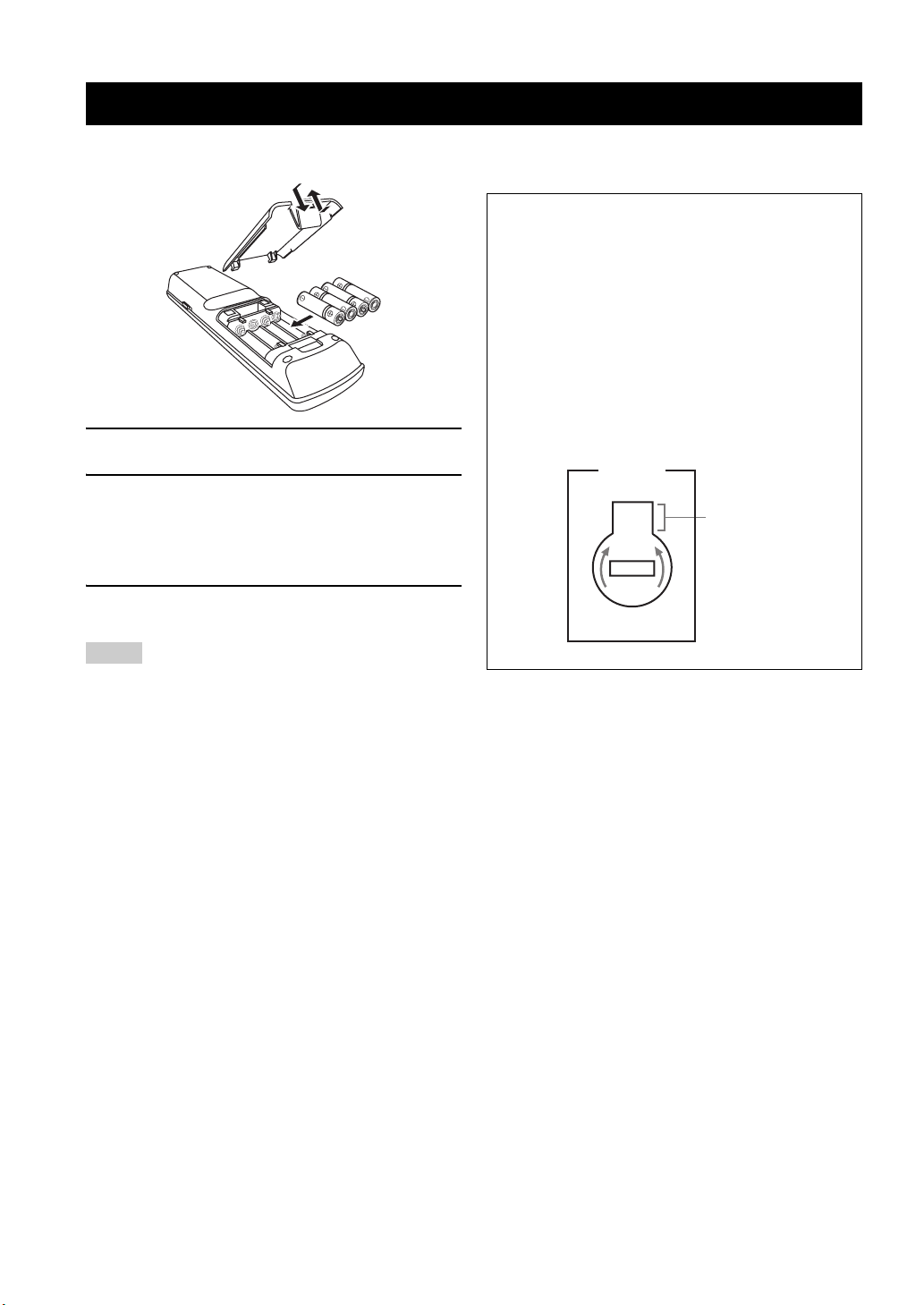
■ Installing batteries in the remote control
1
3
2
1 Take off the battery compartment cover.
2 Insert the four supplied batteries
(AAA, R03, UM-4) according to the polarity
markings (+ and –) on the inside of the
battery compartment.
3 Snap the battery compartment cover back
into place.
Notes
■ VOLTAGE SELECTOR
(Asia and General models only)
Caution
The VOLTAGE SELECTOR on the rear panel of this
unit must be set for your local voltage BEFORE
plugging the power cable into the AC wall outlet.
Improper setting of the VOLTAGE SELECTOR may
cause damage to this unit and create a potential fire
hazard.
Rotate the VOLTAGE SELECTOR clockwise or
counterclockwise to the correct position using a straight
slot screwdriver.
Voltages are as follows:
........................AC 110/120/220/230–240 V, 50/60 Hz
VOLTAGE
SELECTOR
230240V
Voltage indication
• Change all of the batteries if you notice the following
conditions:
– the operation range of the remote control decreases.
– the transmit indicator does not flash or its light becomes dim.
• Do not use old batteries together with new ones.
• Do not use different types of batteries (such as alkaline and
manganese batteries) together. Read the packaging carefully as
these different types of batteries may have the same shape and
color.
• If the batteries have leaked, dispose of them immediately. Avoid
touching the leaked material or letting it come into contact with
clothing, etc. Clean the battery compartment thoroughly before
installing new batteries.
• Do not throw away batteries with general house waste; dispose
of them correctly in accordance with your local regulations.
• If the remote control is without batteries for more than 2
minutes, or if exhausted batteries remain in the remote control,
the contents of the memory may be cleared. When the memory
is cleared, insert new batteries, set up the remote control code
and program any acquired functions that may have been
cleared.
4 En
Quick start guide
QUICK START GUIDE
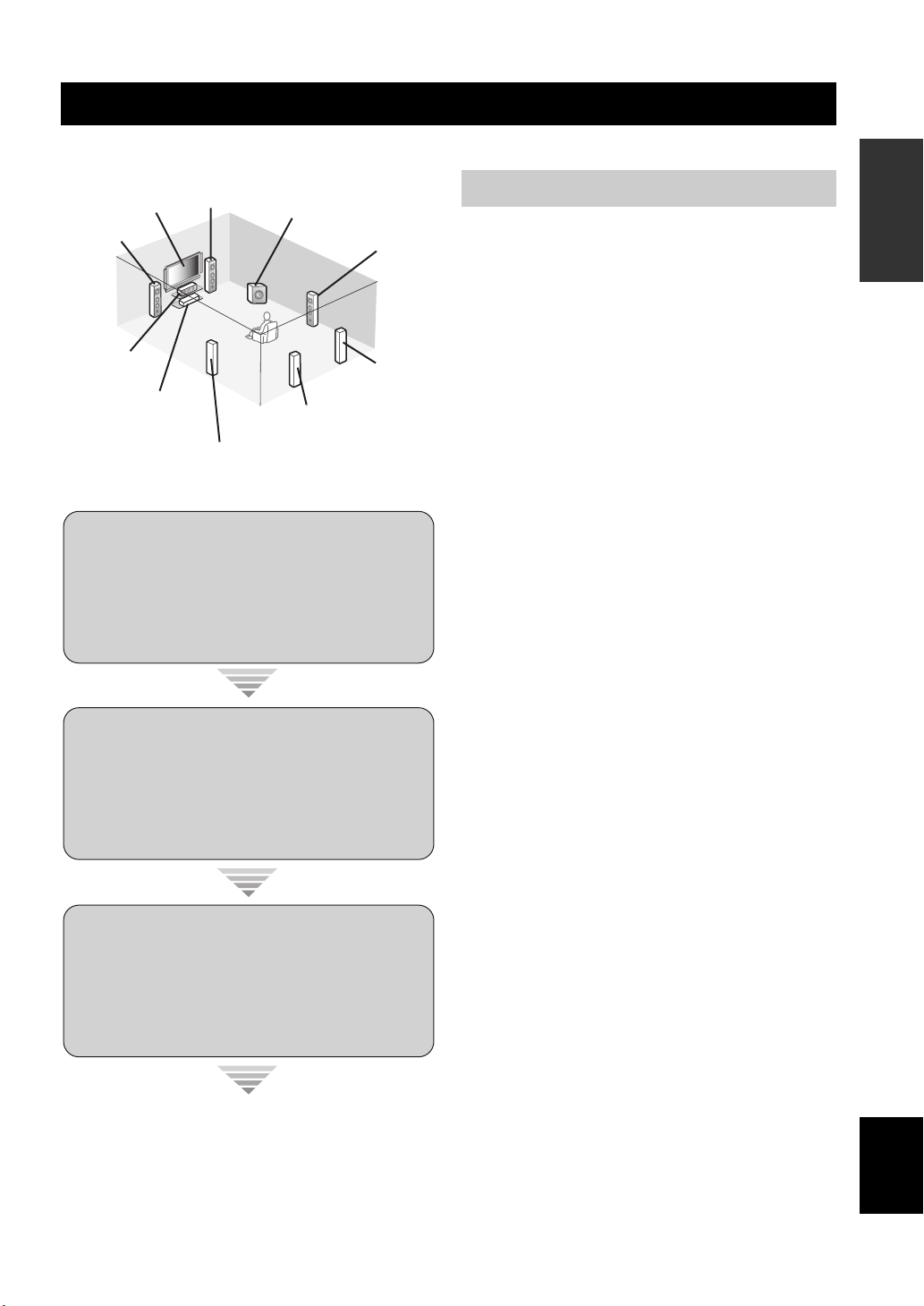
The following steps describe the easiest way to enjoy DVD movie playback in your home theater.
Front right
Video monitor
Front left
speaker
Center
speaker
DVD player
speaker
Surround left
speaker
Subwoofer
Surround right
Surround back left
speaker
Surround back
Step 1: Set up your speakers
☞
speaker
right speaker
P. 6
Preparation: Check the items
In these steps, you need the following supplied
accessories.
❏ Power cable
The following items are not included in the package of this
unit.
❏ Speakers
❏ Front speaker ......................................x 2
❏ Center speaker ...................................x 1
❏ Surround speaker ...............................x 4
Select magnetically shielded speakers. The
minimum required speakers are two front speakers.
The priority of the requirement of other speakers is
as follows:
1. Two surround speakers
2. One center speaker
3. One (or two) surround back speaker(s)
❏ Active subwoofer ....................................x 1
Select an active subwoofer equipped with an RCA
input jack.
INTRODUCTION
Step 2: Connect your DVD player
and other components
☞
P. 7
Step 3: Turn on the power and
start playback
☞
P. 8
Enjoy DVD playback!
❏ Speaker cable ..........................................x 7
❏ Subwoofer cable .....................................x 1
Select a monaural RCA cable.
❏ DVD player ...............................................x 1
Select DVD player equipped with coaxial digital
audio output jack and composite video output
jack.
❏ Video monitor...........................................x 1
Select a TV monitor, video monitor or projector
equipped with a composite video input jack.
❏ Video cable ..............................................x 2
Select RCA composite video cables.
❏ Digital coaxial audio cable .....................x 1
English
5 En
QUICK START GUIDE
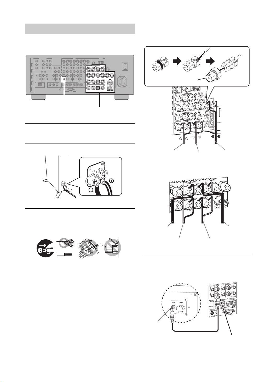
Step 1: Set up your speakers
Place your speakers in the room and connect them to this
unit.
HDMI
COMPONENT VIDEO
MONITOR OUT
BD/HD DVD
DVD
CBL/SAT
A B C
Y
Y
IN4
PBP
B
MD/
IN
(PLAY)
DVR
P
R
IN3
REMOTE
CBL/
SAT
PHONO
GND
IN2
L
DVD
R
IN1
DOCK
BD/
HD DVD
OUT
CD-R
P
R
OUT
IN
CENTER
FRONT(6CH)
CD TV
SUB
WOOFER
SB(8CH)
AUDIO
MULTI CH INPUT
D
V
V
D
D
CD
321
SUBWOOFER PRE OUT Speaker terminals
1 Place your speakers and subwoofer in the
room.
VIDEO
DVD
BD/HD DVD
OUT
(REC)
L
R
SURROUND
CENTER
SUB
WOOFER
DIGITAL INPUT
COAXIAL
R
TV
4
2
1
TRIGGER OUT
CBL/SAT
SURROUND
FRONT
PRE OUT
BD/
65
HD DVD
RS-232C
DVR
ZONE 2
SINGLE(SB)
SUR.BACK/
PRESENCE
ZONE OUT
CBL/
MD/
DVD DVR
SAT
CD-R
OUT OUT
ININ
ZONE 3
DIGITAL OUTPUT
987
VCR
OPTICAL
ANTENNA
MONITOR OUT
AM
FM
GND
75Ω UNBAL.
S VIDEO
VIDEO
SPEAKERS
SP1
L
PRESENCE/ZONE 2/ZONE 3
R
++
SURROUND BACK/
R
+++
SURROUND
R
++
R
++
WRENCH
HOLDER
CENTER
L
BI-AMP
SINGLE
SP2
L
ZONE 2/ZONE 3
L
R
+
L
FRONT
AC OUTLETS
SWITCHED
AC IN
Be sure to connect the left channel (L), right channel
(R), “+” (red) and “–” (black) properly.
Front speakers and center speaker
Loosen Insert
Speaker terminal wrench
Tighten
2 Connect speaker cables to each speaker.
3 Connect each speaker cable to the
corresponding speaker terminal of this unit.
12 3 4
12 3 4
1 Make sure that this unit and the subwoofer are
unplugged from the AC wall outlets.
2 Twist the exposed wires of the speaker cables
together to prevent short circuits.
3 Do not let the bare speaker wires touch each other.
4 Do not let the bare speaker wires touch any metal
part of this unit.
To the front right
speaker
To the front left
speaker
To the center
speaker
Surround and surround back speakers
To the surround
back
right speaker
To the surround right
speaker
To the surround left
speaker
To the surround
back left
speaker
4 Connect the subwoofer cable to the
SUBWOOFER PRE OUT jack of this unit and
the input jack of the subwoofer.
AV receiverSubwoofer
6 En
Input jack
Subwoofer cable
SUBWOOFER PRE OUT jack
Quick start guide
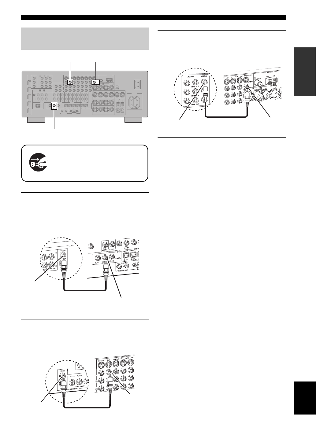
Step 2: Connect your DVD player
and other components
VIDEO MONITOR OUTDVD VIDEO
HDMI
COMPONENT VIDEO
MONITOR OUT
BD/HD DVD
DVD
CBL/SAT
A B C
Y
Y
IN4
PBP
B
MD/
IN
(PLAY)
P
R
OUT
IN
CD TV
AUDIO
CD-R
CENTER
FRONT(6CH)
SUB
WOOFER
SB(8CH)
MULTI CH INPUT
D
V
D
CD
321
COAXIAL
V
D
DVR
P
R
IN3
REMOTE
CBL/
SAT
PHONO
GND
IN2
L
DVD
R
IN1
DOCK
BD/
HD DVD
OUT
DVD DIGITAL INPUT
Make sure that this unit and the DVD
player are unplugged from the AC
wall outlets.
1 Connect the digital coaxial audio cable to the
digital coaxial audio output jack of your DVD
player and the DVD DIGITAL INPUT COAXIAL
jack of this unit.
VIDEO
DVD
BD/HD DVD
OUT
(REC)
L
R
SURROUND
CENTER
SUB
WOOFER
DIGITAL INPUT
COAXIAL
R
TV
4
2
1
TRIGGER OUT
CBL/SAT
SURROUND
FRONT
PRE OUT
BD/
65
HD DVD
RS-232C
DVR
ZONE 2
SINGLE(SB)
SUR.BACK/
PRESENCE
ZONE OUT
CBL/
DVD DVR
SAT
CD-R
OUT OUT
ININ
ZONE 3
DIGITAL OUTPUT
MD/
987
VCR
OPTICAL
ANTENNA
MONITOR OUT
AM
FM
GND
75Ω UNBAL.
S VIDEO
VIDEO
SPEAKERS
SP1
L
PRESENCE/ZONE 2/ZONE 3
R
++
SURROUND BACK/
R
+++
R
++
R
++
WRENCH
HOLDER
CENTER
L
BI-AMP
SINGLE
SP2
L
SURROUND
ZONE 2/ZONE 3
L
R
+
L
FRONT
AC OUTLETS
SWITCHED
AC IN
3 Connect the video cable to the VIDEO
MONITOR OUT jack of this unit and the video
input jack of your video monitor.
Video monitor
Video input jack
Video cable
AV receiver
VIDEO MONITOR
OUT jack
4 Connect the supplied power cable to this unit
and then plug of the power cable and other
components into the AC wall outlet.
y
For details about connecting the power cable, see page 24.
■ For other connections
• Other speaker combinations ☞ P. 12
• Information on jacks and cable plugs ☞ P. 15
• Information on HDMI™ ☞ P. 16
INTRODUCTION
Digital coaxial
audio output
jack
DVD player
Digital coaxial audio
cable
AV receiver
DVD DIGITAL INPUT
COAXIAL jack
2 Connect the video cable to the composite
video output jack of your DVD player and
DVD VIDEO jack of this unit.
AV receiver
DVD VIDEO jack
Composite video
output jack
DVD player
Video cable
• TV monitor or projector ☞ P. 18
• Other components ☞ P. 19
• External amplifier ☞ P. 21
• Multi-format player or external
decoder ☞ P. 22
• Yamaha iPod universal dock or
Bluetooth wireless audio receiver ☞ P. 22
•FM/AM antennas ☞ P. 23
• USB memory device or
USB portable audio player ☞ P. 23
English
7 En
Quick start guide
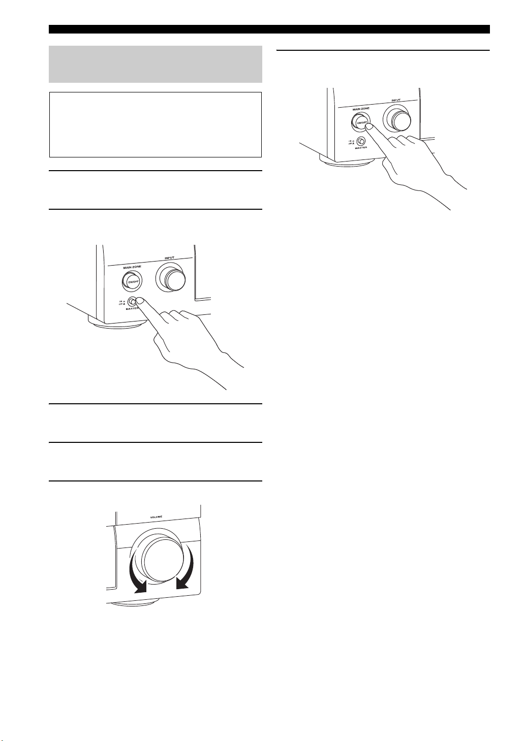
Step 3: Turn on the power and start
playback
Check the type of the connected speakers.
If the speakers are 6-ohm speakers, set “SPEAKER
IMP.” to “6Ω MIN” before using this unit (page 25).
You can also use 4-ohm speakers as the front speakers
(page 93).
1 Turn on the video monitor connected to this
unit.
2 Press
A
MASTER ON/OFF inward to the ON
position on the front panel.
6 To set this unit to the standby mode, press B
MAIN ZONE ON/OFF.
y
For details about turning on/off this unit and the standby
mode, see pages 25.
■ For other operations
• Optimizing the speaker parameters
automatically ☞ P. 29
• Basic playback operations ☞ P. 34
• Sound field programs ☞ P. 38
• Pure high-fidelity sounds ☞ P. 45
3 Rotate the
source to “DVD”.
C
INPUT selector to set the input
4 Start playback of the desired DVD on your
player.
5 Rotate
Q
VOLUME to adjust the volume.
• FM/AM radio tuning ☞ P. 46
• iPod playback ☞ P. 52
• Bluetooth component playback ☞ P. 54
• USB content playback ☞ P. 55
8 En
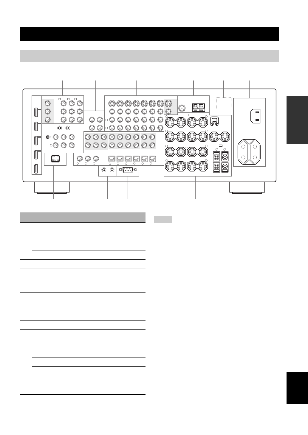
Rear panel
Connections
2314567
HDMI
HD DVD
DVR
CBL/
SAT
DVD
BD/
OUT
IN4
IN3
IN2
IN1
MONITOR OUT
Y
P
B
P
R
REMOTE
GND
DOCK
COMPONENT VIDEO
PHONO
L
R
8
BD/HD DVD
A B C
Y
P
B
P
R
OUT
IN
CD TV
AUDIO
DVD
BD/HD DVD
DVD
CBL/SAT
OUT
MD/
IN
(PLAY)
CD-R
(REC)
L
FRONT(6CH)
SB(8CH)
MULTI CH INPUT
D
V
321
D
V
R
COAXIAL
SURROUND
DIGITAL INPUT
1
TRIGGER OUT
R
CENTER
SUB
WOOFER
D
CD
CBL/SAT
SURROUND
FRONT
PRE OUT
BD/
DVD DVR
65
HD DVD
RS-232C
SINGLE(SB)
SUR.BACK/
PRESENCE
CENTER
SUB
WOOFER
TV
4
2
0A9
Name Page
1 HDMI jacks 16
2 COMPONENT VIDEO jacks 15
3 Audio component jacks 15
REMOTE IN/OUT jacks 22, 90
4 Video component jacks 15
5 ANTENNA terminals 23
6 VOLTAGE SELECTOR
(Asia and General models only)
7 AC IN 24
AC OUTLET(S) 24
8 DOCK terminal 22
9 DIGITAL INPUT/OUTPUT jacks 15
0 TRIGGER OUT jacks —
A RS-232C terminal —
B MULTI CH INPUT jacks 22
PRE OUT jacks 21
ZONE OUT jacks 90
Speaker terminals 12
WRENCH HOLDER 14
VIDEO
24
CBL/
SAT
DVR
OUT OUT
ZONE 2
ZONE OUT
DIGITAL OUTPUT
MD/
CD-R
MONITOR OUT
VCR
ININ
S VIDEO
VIDEO
R
++
R
ZONE 3
+++
R
++
R
OPTICAL
++
987
FM
75Ω UNBAL.
SP1
PRESENCE/ZONE 2/ZONE 3
SURROUND BACK/
BI-AMP
SURROUND
FRONT
ANTENNA
GND
SINGLE
AM
SPEAKERS
L
WRENCH
HOLDER
CENTER
L
SP2
L
ZONE 2/ZONE 3
L
R
+
L
B
Notes
• The TRIGGER OUT jacks are control expansion terminals for
custom installation.
• The RS-232C terminal is a control expansion terminal for
factory use only. Consult your dealer for details.
AC OUTLETS
SWITCHED
AC IN
PREPARATION
English
9 En
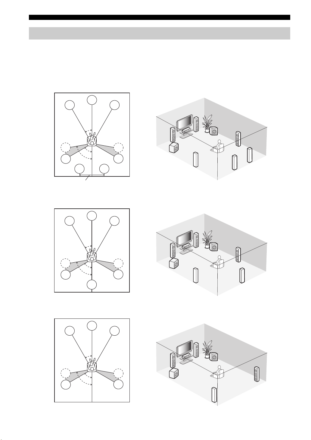
Connections
Placing speakers
The speaker layout below shows the speaker setting we recommend.
y
• 7.1-channel speaker layout is highly recommended for playback of the high definition digital audio sources (Dolby TrueHD, DTS-HD
Master Audio, etc.) with sound field programs.
• We recommend that you add the presence speakers for the effect sounds of the CINEMA DSP sound field program.
7.1-channel speaker layout
80˚
SBL
C
30˚
60˚
FL
SL
SL
30 cm (12 in) or more
6.1-channel speaker layout
FL
SL
SL
C
30˚
60˚
80˚
SB
SBR
FR
FR
FL
SW
SR
C
SR
SR
SW
SL
SBR
SBL
FR
FR
FL
SW
SR
C
SR
SR
SW
SL
SB
5.1-channel speaker layout
FL
SL
SL
C
30˚
60˚
80˚
10 En
FR
FR
FL
SW
C
SR
SR
SW
SR
SL
Connections
■ Speaker types
Front left and right speakers (FL and FR)
The front speakers are used for the main source sound plus
effect sounds. Place these speakers at an equal distance from
the ideal listening position. The distance of each speaker
from each side of the video monitor should be the same.
Center speaker (C)
The center speaker is for the center channel sounds
(dialog, vocals, etc.). If for some reason it is not practical
to use a center speaker, you can do without it. Best results,
however, are obtained with the full system.
Surround left and right speakers (SL and SR)
The surround speakers are used for effect and surround
sounds.
For 5.1-channel speaker layout, place these speakers
farther back compared with the placement in the 7.1channel speaker layout.
Surround back left and right speakers (SBL and
SBR) / Surround back speaker (SB)
The surround back speakers supplement the surround
speakers and provide more realistic front-to-back
transitions.
For 6.1-channel speaker layout, surround back left and
right channel signals are mixed down and output at the
single surround back speaker by configuring the “SUR.B
L/R SP” setting (page 68).
For 5.1-channel speaker layout, surround back left and
right channel signals are output at the surround left and
right speakers by configuring the “SUR.B L/R SP” setting
(page 68).
Subwoofer (SW)
The use of a subwoofer with a built-in amplifier, such as
the Yamaha Active Servo Processing Subwoofer System,
is effective not only for reinforcing bass frequencies from
any or all channels, but also for reproducing the high
fidelity sound of the LFE (low-frequency effect) channel
included in bitstreams and multi-channel PCM sources.
The position of the subwoofer is not so critical, because
low bass sounds are not highly directional. But it is better
to place the subwoofer near the front speakers. Turn it
slightly toward the center of the room to reduce wall
reflections.
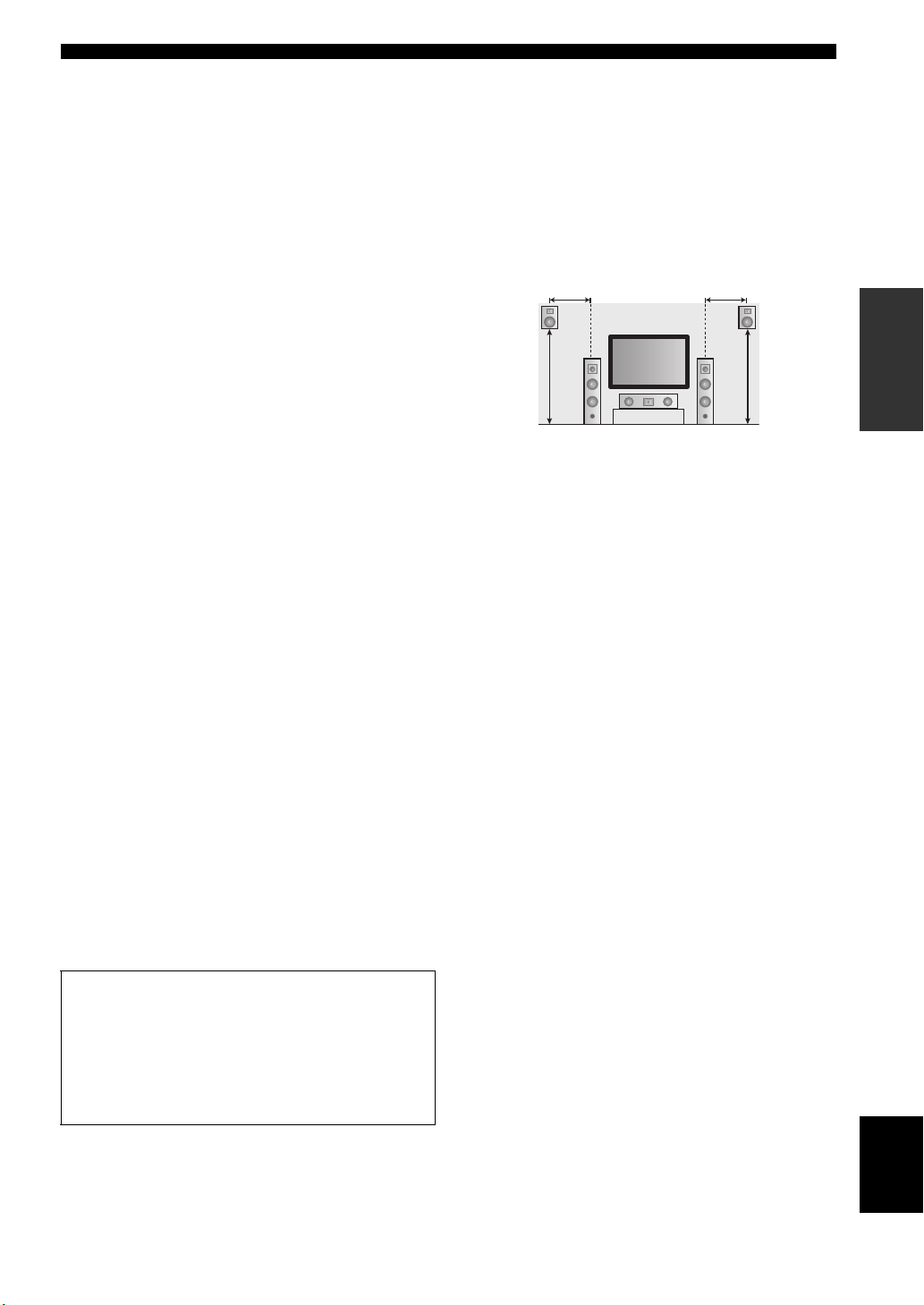
■ Presence left and right speakers
(PL and PR)
The presence speakers supplement the sound from the front
speakers with extra ambient effects produced by the sound
field programs (page 38). We recommend that you use the
presence speakers especially for the CINEMA DSP sound
field programs. To use the presence speakers, connect the
speakers to SP1 speaker terminals and then set
“PRESENCE SP” to “YES” (page 68).
0.5 to 1 m (1 to 3 ft) 0.5 to 1 m (1 to 3 ft)
PRPL
1.8 m (6 ft)
FL
C
FR
1.8 m (6 ft)
PREPARATION
For other speaker combinations
You can enjoy multi-channel sources with sound field
programs by using a speaker combination other than
the 7.1/6.1/5.1-channel speaker combinations.
Use the automatic setup feature (page 29) or set the
“SPEAKER MENU” parameters (page 67) to output
the surround sounds at the connected speakers.
English
11 En
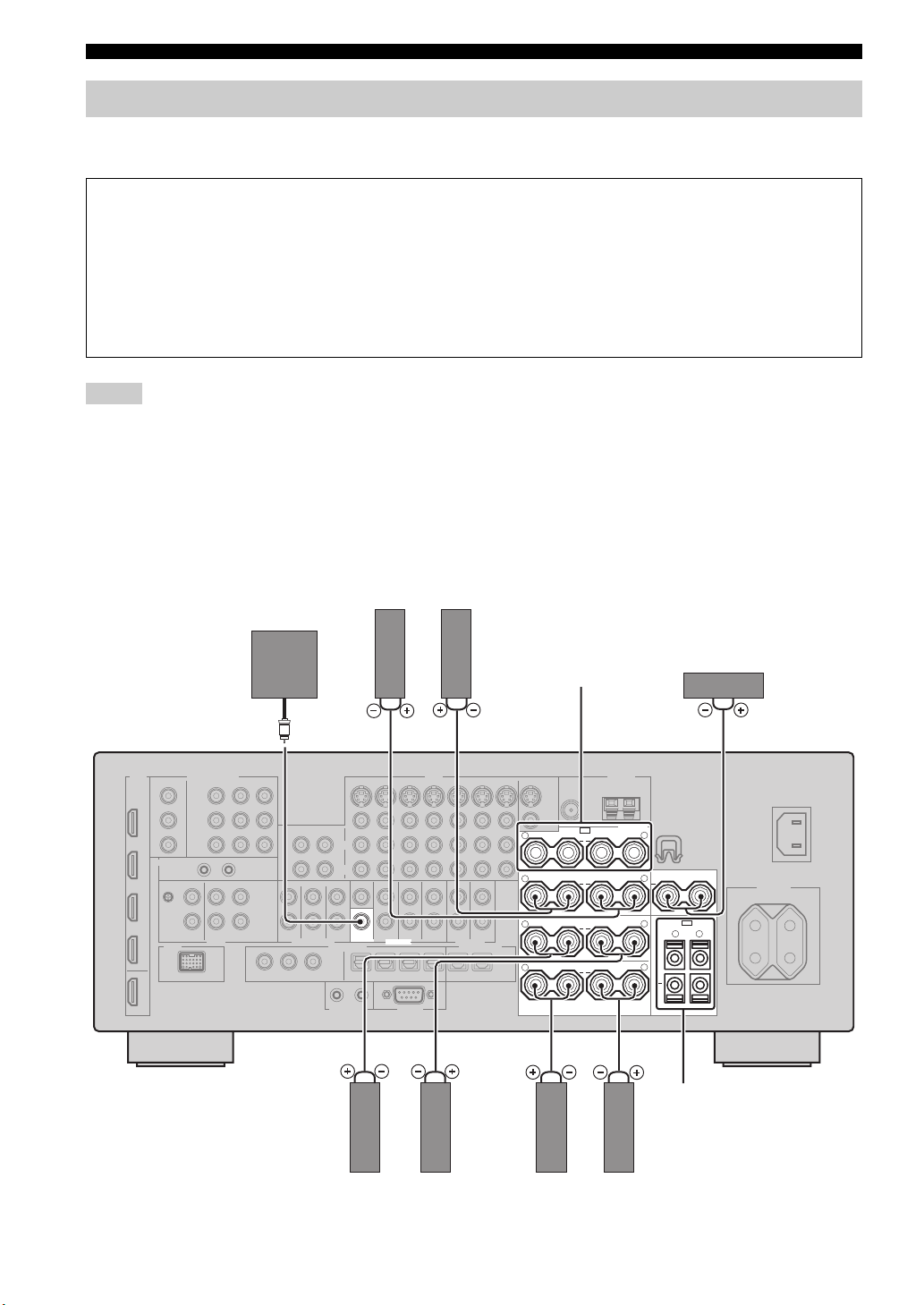
Connections
Connecting speakers
Be sure to connect the left channel (L), right channel (R), “+” (red) and “–” (black) properly. If the connections are faulty,
this unit cannot reproduce the input sources accurately.
Caution
• Before connecting the speakers, make sure that this unit is turned off (page 25).
• Do not let the bare speaker wires touch each other or do not let them touch any metal part of this unit. This could
damage this unit and/or speakers.
• Use magnetically shielded speakers. If this type of speaker still creates interference with the monitor, place the
speakers away from the monitor.
• If you are to use 6-ohm speakers, be sure to set “SPEAKER IMP.” to “6Ω MIN” before using this unit (page 25).
You can also use 4-ohm speakers as the front speakers (page 93).
Notes
• A speaker cord is actually a pair of insulated cables running side by side. Cables are colored or shaped differently, perhaps with a
stripe, groove or ridge. Connect the striped (grooved, etc.) cable to the “+” (red) terminals of this unit and your speaker. Connect the
plain cable to the “–” (black) terminals.
• You can connect both surround back and presence speakers to this unit, however they do not output sound simultaneously. This unit
automatically switches the presence speakers and surround back speakers depending on the input sources and the selected sound field
programs.
■ 7.1-channel speaker connection
Subwoofer
Surround back speakers
Left
WOOFER
Right
PRE OUT
Presence speakers
(page 11) or
Zone 2/Zone 3
speakers
(page 90)
SPEAKERS
SP1
PRESENCE/ZONE 2/ZONE 3
R
++
SURROUND BACK/
R
+++
R
++
R
++
BI-AMP
SURROUND
FRONT
SINGLE
Center speaker
L
CENTER
L
SP2
L
ZONE 2/ZONE 3
R
+
L
L
Zone 2/Zone 3 speakers
(page 90)
12 En
Right
Left
Surround speakers
Right
Left
Front speakers
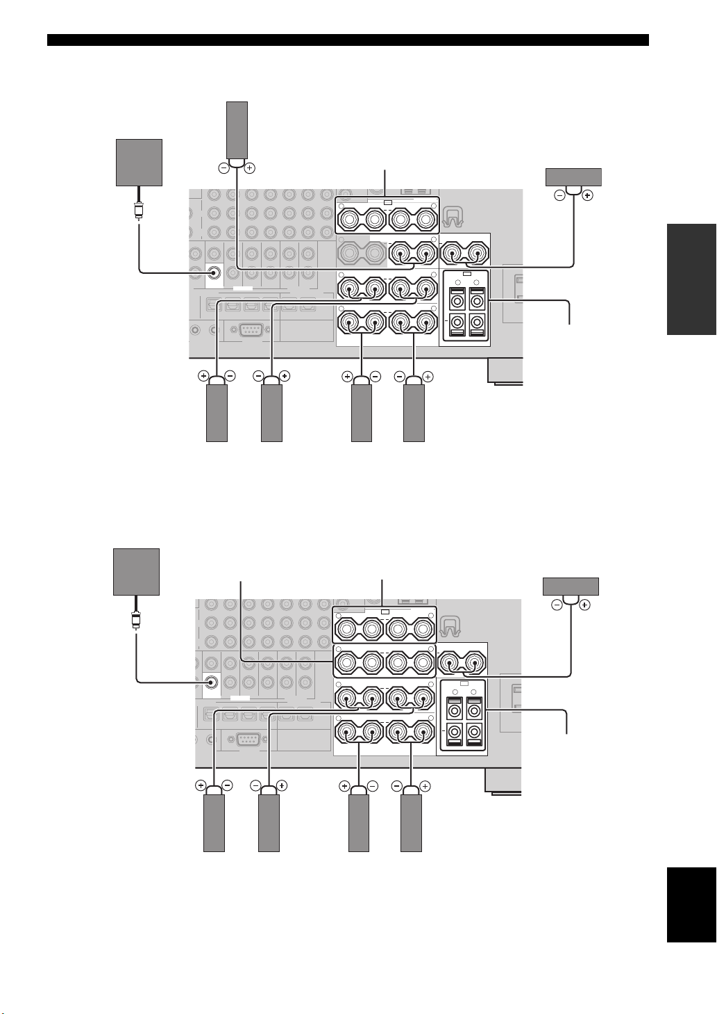
■ 6.1-channel speaker connection
Surround back speaker
Connections
Subwoofer
SUB
WOOFER
PRE OUT
Right
Left
Surround speakers
■ 5.1-channel speaker connection
Presence speakers
(page 11) or
Zone 2/Zone 3 speakers
(page 90)
SPEAKERS
SP1
PRESENCE/ZONE 2/ZONE 3
R
++
SURROUND BACK/
R
+ + +
++
++
BI-AMP
SURROUND
R
FRONT
R
Right
SINGLE
Left
L
CENTER
L
SP2
L
ZONE 2/ZONE 3
L
R
+
L
Front speakers
Center speaker
PREPARATION
Zone 2/Zone 3
speakers
(page 90)
Subwoofer
Front speakers for the
bi-amplification
connections
(page 14)
SUB
WOOFER
PRE OUT
Right
Left
Surround speakers
Presence speakers
(page 11) or
Zone 2/Zone 3 speakers
(page 90)
SPEAKERS
SP1
PRESENCE/ZONE 2/ZONE 3
R
++
SURROUND BACK/
R
+++
R
++
R
++
BI-AMP
SURROUND
FRONT
Right
SINGLE
Left
L
CENTER
L
SP2
L
ZONE 2/ZONE 3
L
R
+
L
Front speakers
Center speaker
Zone 2/Zone 3
speakers
(page 90)
English
13 En
Connections
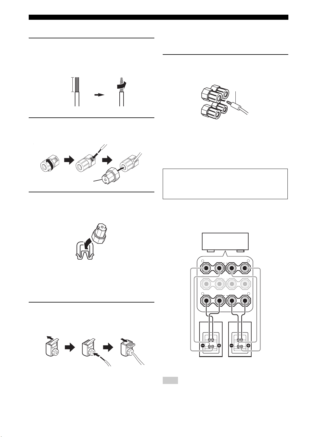
■ Connecting the speaker cable
1 Remove approximately 10 mm (0.4 in) of
insulation from the end of each speaker
cable and then twist the exposed wires of the
cable together to prevent short circuits.
10 mm (0.4 in)
2 Loosen the knob using the supplied speaker
terminal wrench, insert one bare wire into the
hole and then tighten the knob.
Loosen Insert
Speaker terminal wrench
Tighten
3 Hook the speaker terminal wrench onto
WRENCH HOLDER on the rear panel of this
unit when not in use.
■ Connecting the banana plug
(Except U.K., Europe, Asia and Korea
models)
Tighten the knob using the supplied speaker
terminal wrench and then insert the banana plug
into the end of the terminal.
Banana plug
y
You can also use the banana plug with the SP2 speaker
terminals. Open the tab and then insert one banana plug into the
hole on the terminal. Do not close the tab after connecting the
banana plug.
■ Using bi-amplification connections
Caution
Remove the shorting bars or bridges of your speakers to
separate the LPF (low pass filter) and HPF (high pass filter)
crossovers.
You can make bi-amplification connections to one speaker
system which supports bi-amplification connection as
shown below. To activate the connections, configure the
“BI-AMP” setting (page 94).
■ Connecting to the SP2 speaker
terminals
Connect Zone 2 or Zone 3 speakers to these terminals
(page 90).
Open the tab, insert one bare wire into the hole
and then close the tab.
Open the tab Insert Close the tab
This unit
SURROUND BACK/
R
+
R
+ +
R
++
BI-AMP
SURROUND
FRONT
Front speakers
L
SINGLE
+
L
L
LeftRight
Note
When you make the conventional connection with the speakers,
make sure that the shorting bars are put into the terminals of the
speakers appropriately. Refer to the instruction manuals of the
speakers for details.
14 En

Connections
Information on jacks and cable plugs
This unit has three types of audio jacks, three types of video jacks and HDMI jacks. You can choose the connection
method depending on the component to be connected.
■ Audio jacks
AUDIO
L
L
Left and right
analog audio
cable plugs
R
(Red)(White) (Orange)
R
DIGITAL
COAXIAL
C
Coaxial
digital audio
cable plug
AUDIO jacks
For conventional analog audio signals transmitted via left
and right analog audio cables. Connect red plugs to the
right jacks and white plugs to the left jacks.
COAXIAL jacks
For digital audio signals transmitted via coaxial digital
audio cables.
OPTICAL jacks
For digital audio signals transmitted via optical digital
audio cables.
Note
You can use the digital jacks to input PCM, Dolby Digital and
DTS bitstreams. When you connect components to both the
COAXIAL and OPTICAL jacks, priority is given to the signals
input at the COAXIAL jack. All digital input jacks are
compatible with up to 96-kHz sampling digital signals.
DIGITAL
OPTICAL
O
Optical
digital
audio cable
plug
■ Video jacks
VIDEO S VIDEO
(Yellow) (Green) (Blue) (Red)
V
Composite
video cable
plug
S
S-video
cable plug
VIDEO jacks
For conventional composite video signals transmitted via
composite video cables.
S VIDEO jacks
For S-video signals, separated into the luminance (Y) and
chrominance (C) video signals transmitted on separate
wires of S-video cables.
COMPONENT VIDEO jacks
For component video signals, separated into the
luminance (Y) and chrominance (P
transmitted on separate wires of component video cables.
y
This unit is equipped with the video conversion function.
(page 17)
COMPONENT VIDEO
Y
Y
B
P
PB
Component
video cable
plugs
B, PR) video signals
R
P
P
R
PREPARATION
15 En
English
Connections
Information on HDMI™
This unit has four HDMI input jacks and one HDMI output jack for digital audio and video signal input/output.
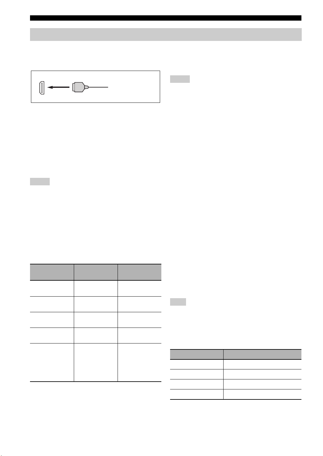
■ HDMI jack and cable plug
HDMI
HDMI cable plug
y
• We recommend that you use a commercially available HDMI
cable shorter than 5 meters (16 feet) with the HDMI logo
printed on it.
• Use a conversion cable (HDMI jack
this unit to other DVI components.
• You can check the potential problem about the HDMI
connection (page 36).
• This unit is equipped with the video conversion function
(page 17).
↔ DVI-D jack) to connect
Notes
• Do not disconnect or connect the cable or turn off the power of
the HDMI components connected to the HDMI OUT jack of
this unit while data is being transferred. Doing so may disrupt
playback or cause noise.
• The HDMI OUT jack outputs the audio signals input at the
HDMI input jacks only.
• If you turn off the video monitor connected to the HDMI OUT
jack via a DVI connection, the connection may fail.
■ HDMI signal compatibility with this unit
Audio signals
Audio signal
types
2ch Linear
PCM
Multi-ch
Linear PCM
DSD 2/5.1ch,
Bitstream Dolby Digital,
Bitstream (High
definition audio)
y
• If the input source component can decode the bitstream audio
signals of audio commentaries, you can play back the audio
sources with the audio commentaries mixed down by using the
following connections:
– multi-channel analog audio input (page 22)
– DIGITAL INPUT OPTICAL (or COAXIAL)
Audio signal
formats
2ch, 32-192 kHz,
16/20/24 bit
8ch, 32-192 kHz,
16/20/24 bit
2.8224 MHz,1 bit
DTS
Dolby TrueHD,
Dolby Digital Plus,
DTS-HD Master
Audio, DTS-HD
High Resolution
Audio
Compatible
media
CD, DVD-Video,
DVD-Audio, etc.
DVD-Audio, etc.
SACD, etc.
DVD-Video, etc.
Blu-ray Disc,
HD DVD, etc.
• Refer to the instruction manuals of the input source component,
and set the component appropriately.
Notes
• When CPPM copy-protected DVD audio is played back, video
and audio signals may not be output depending on the type of
the DVD player.
• This unit is not compatible with HDCP-incompatible HDMI or
DVI components.
• To decode the audio bitstream signals on this unit, set the input
source component appropriately so that the component outputs
the audio bitstream signals directly (does not decode the
bitstream signals on the component).
• This unit is not compatible with the audio commentary features
(for example, the special audio contents downloaded via
Internet) of Blu-ray Disc or HD DVD. This unit does not play
back the audio commentaries of the Blu-ray Disc or HD DVD
contents.
Video signals
This unit is compatible with the video signals of the
following resolutions:
– 480i/60 Hz
– 576i/50 Hz
– 480p/60 Hz
– 576p/50 Hz
– 720p/60 Hz, 50 Hz
– 1080i/60 Hz, 50 Hz
– 1080p/60 Hz, 50 Hz, 24Hz
Compatibility with Deep Color and x.v.Color
video signals
This unit accepts Deep Color (30 or 36-bit) and x.v.Color
video signals. To output those video signals from the
HDMI OUT jack without any processing, set “HDMI
RES.” to “THRGH” (page 73).
Note
If the video monitor is not compatible with Deep Color or
x.v.Color video signals, the video source may not be played
back correctly.
■ Default input assignment of HDMI input
jacks
HDMI input jack Assigned input source
IN1 BD/HD DVD
IN2 DVD
IN3 CBL/SAT
IN4 DVR
16 En
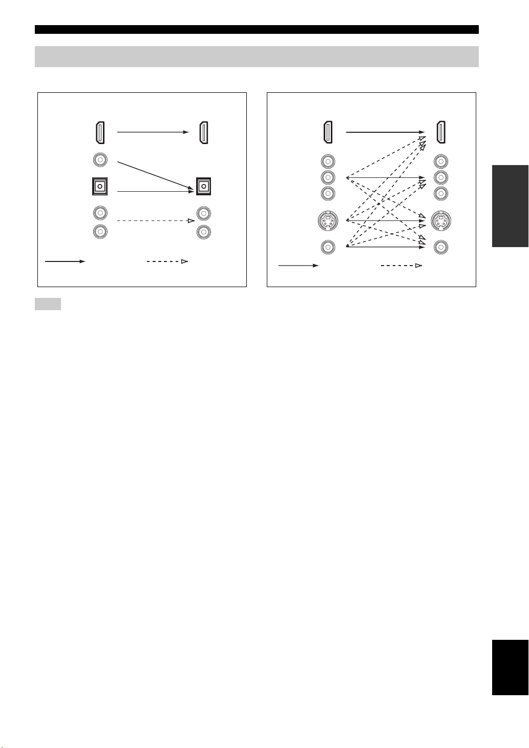
Audio and video signal flow
Connections
■ Audio signal flow
OutputInput
HDMI
DIGITAL AUDIO
(COAXIAL)
DIGITAL AUDIO
(OPTICAL)
AUDI O
Digital
Note
Only the HDMI input jacks support DSD, Dolby TrueHD,
Dolby Digital Plus, DTS-HD Master Audio and DTS-HD High
Resolution Audio signal inputs.
Analog
■ Video signal flow
OutputInput
HDMI
COMPONENT
VIDEO
S VIDEO
VIDEO
Through
y
• To set the video conversion or change other video settings,
configure the “VIDEO MENU” parameters (page 72).
• If different analog video signals are input concurrently, the
following priority order will be applied:
(1) COMPONENT VIDEO, (2) S VIDEO, (3) VIDEO.
Video
conversion
PREPARATION
17 En
English
Connections
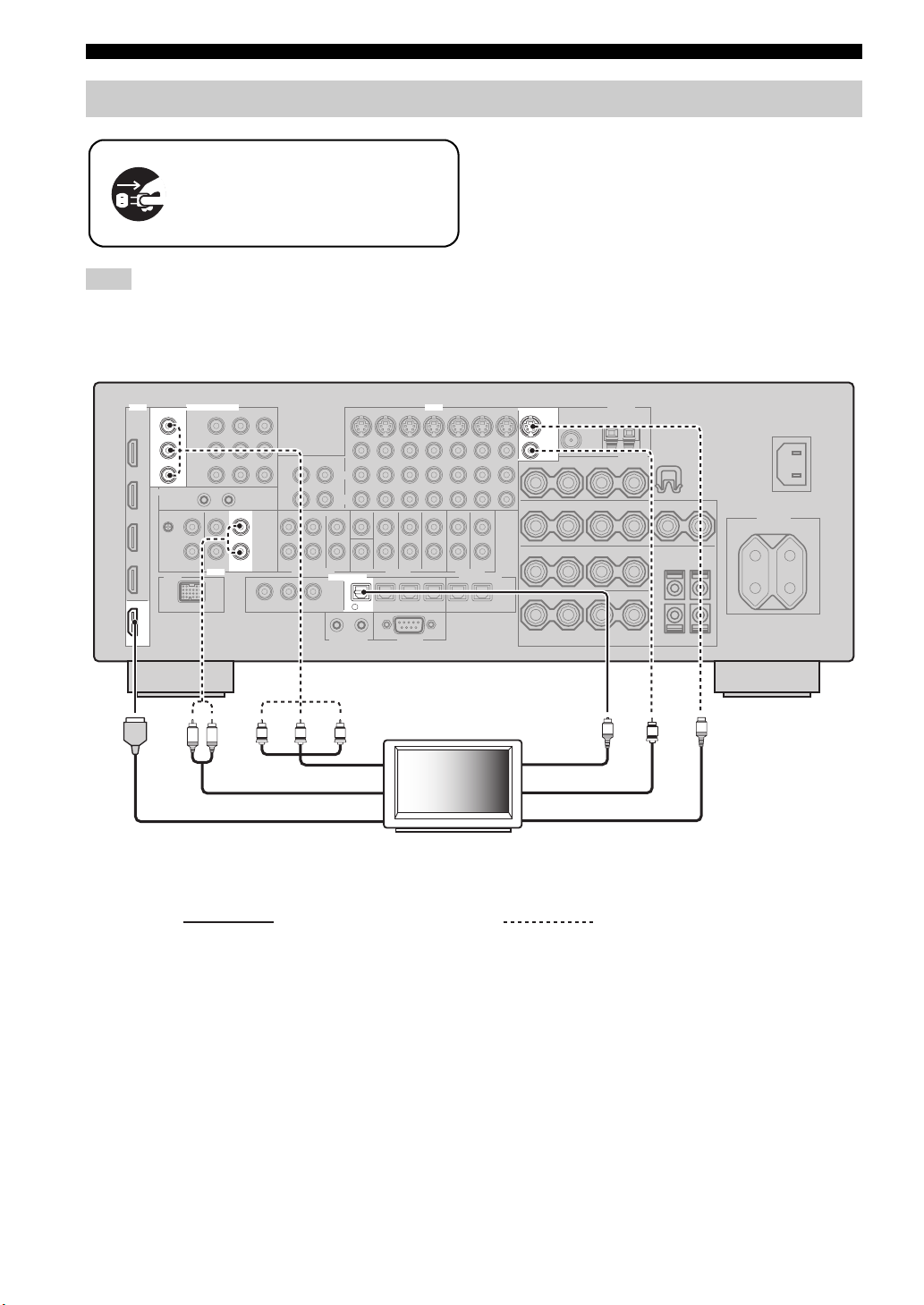
Connecting a TV monitor or projector
Make sure that this unit and other
components are unplugged from the
AC wall outlets.
Note
If you turn off the video monitor connected to the HDMI OUT
jack via a DVI connection, the connection may fail. In this case,
the HDMI indicator flashes irregularly.
y
To select the types of the audio signals output at the HDMI
OUT jack, configure the “HDMI AUDIO” setting (page 72).
HDMI
OUT
MONITOR OUT
Y
P
B
P
R
COMPONENT VIDEO
AUDIO
L R
VIDEO
TV
DIGITAL INPUT
TV
4
Y
PRPB
MONITOR OUT
S VIDEO
VIDEO
O
S
V
Optical outComponent video in
Audio out
HDMI in
TV
Video in
S-video in
(or projector)
Recommended connections Alternative connections
18 En
Connections
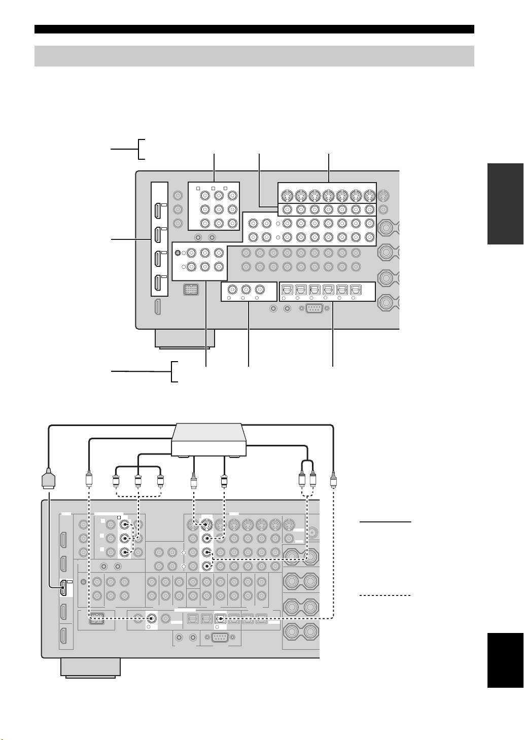
Connecting other components
■ Connecting audio and video components
This unit has three types of audio jacks, three types of video jacks and HDMI jacks. You can choose the connection
method depending on the component to be connected.
y
HDMI can transmit both digital audio and video over a single HDMI cable.
Video jacks
HDMI jacks
Audio jacks
COMPONENT VIDEO VIDEO S VIDEO
HDMI
HD DVD
COMPONENT VIDEO
BD/HD DVD
DVD
A B C
Y
IN4
DVR
IN3
CBL/
SAT
IN2
DVD
IN1
BD/
P
B
P
R
PHONO
GND
L
R
CBL/SAT
CD TV
AUDIO
AUDIO COAXIAL OPTICAL
Connection example (connecting a DVD player)
PRPBY
S-video
out
DVD player
S
Video out
V
HDMI out
Coaxial out
Component out
C
PREPARATION
VIDEO
DVD
BD/HD DVD
CBL/SAT
OUT
MD/
IN
(PLAY)
CD-R
(REC)
L
R
COAXIAL
R
V
VD
D
D
CD
321
BD/
DVD DVR
65
HD DVD
CBL/
SAT
TV
4
Optical out
Audio out
L R
DVR
OUT OUT
MD/
CD-R
O
VCR
ININ
OPTICAL
987
HDMI
COMPONENT VIDEO
DVD
B
Y
P
B
P
R
IN2
DVD
V
D
2
L
R
DIGITAL INPUT
COAXIAL
D
VIDEO
DVD
S VIDEO
VIDEO
Recommended
connections
Alternative
connections
DVD
6
OPTICAL
English
19 En

Connections
Jacks used for audio and video connections
Recommended connections are indicated by boldface. When connecting a recording component, you need to make
additional connections for recording (signal transmission from this unit to the recording component).
Make sure that this unit and other
components are unplugged from the
AC wall outlets.
y
You can also use the VIDEO AUX jacks (page 23) on the front panel to connect an additional component.
Component Signal type
Blu-ray Disc or HD
DVD player
DVD player Audio/Video HDMI out HDMI IN2 (DVD)
Set-top box Audio/Video HDMI out HDMI IN3 (CBL/SAT)
DVD recorder Audio/Video HDMI out HDMI IN4 (DVR)
Audio/Video HDMI out HDMI IN1 (BD/HD DVD)
Audio Optical out OPTICAL (BD/HD DVD)
Video Component out COMPONENT VIDEO (BD/HD DVD)
Audio Optical out OPTICAL (DVD)
Video Component out COMPONENT VIDEO (DVD)
Audio Optical out OPTICAL (CBL/SAT)
Video Component out COMPONENT VIDEO (CBL/SAT)
Audio Coaxial out COAXIAL (DVR)
Video S-video out S VIDEO (DVR IN)
Audio recording Optical in OPTICAL (DVR)
Video recording S-video in S VIDEO (DVR OUT)
On component On this unit
Audio out (analog) AUDIO (BD/HD DVD)
S-video out S VIDEO (BD/HD DVD)
Video out (composite) VIDEO (BD/HD DVD)
Coaxial out COAXIAL (DVD)
Audio out (analog) AUDIO (DVD)
S-video out S VIDEO (DVD)
Video out (composite) VIDEO (DVD)
Audio out (analog) AUDIO (CBL/SAT)
S-video out S VIDEO (CBL/SAT)
Video out (composite) VIDEO (CBL/SAT)
Audio out (analog) AUDIO (DVR IN)
Video out (composite) VIDEO (DVR IN)
Audio in (analog) AUDIO (DVR OUT)
Video in (composite) VIDEO (DVR OUT)
Jacks to connect
20 En
Connections
Component Signal type
Jacks to connect
On component On this unit
VCR Audio Audio out (analog) AUDIO (VCR IN)
Vid eo S-video out S VIDEO (VCR IN)
Video out (composite) VIDEO (VCR IN)
Audio recording Audio in (analog) AUDIO (VCR OUT)
Video recording S-video in S VIDEO (VCR OUT)
Video in (composite) VIDEO (VCR OUT)
CD player Audio Coaxial out COAXIAL (CD)
Audio out (analog) AUDIO (CD)
MD or CD recorder Audio Audio out (analog) AUDIO (MD/CD-R IN)
Audio recording Optical in OPTICAL (MD/CD-R)
Audio in (analog) AUDIO (MD/CD-R OUT)
Turntable Audio Audio out (analog) AUDIO (PHONO)
Notes
• Be sure to make the same type of video connections as those made for your TV if the video conversion is disabled. For example, if you
connected your TV to the VIDEO MONITOR OUT jack of this unit, connect other components to the VIDEO jacks.
• Check the copyright laws in your country to record from CDs, radio, etc. Recording of copyrighted material may infringe copyright
laws.
• If you connect your DVD player to both the OPTICAL and COAXIAL jacks, priority is given to the signals input at the COAXIAL
jack.
• OSD signals are not output at the DVR OUT and VCR OUT jacks and cannot be recorded.
• To make a digital connection to a component other than the default one assigned to each DIGITAL INPUT or DIGITAL OUTPUT
jack, configure the “I/O ASSIGNMENT” setting (page 74).
• When connecting a turntable with a low-output MC cartridge to the PHONO jack, use an in-line boosting transformer or MC-head
amplifier.
• Connect your turntable to the GND terminal of this unit to reduce noise in the signal.
PREPARATION
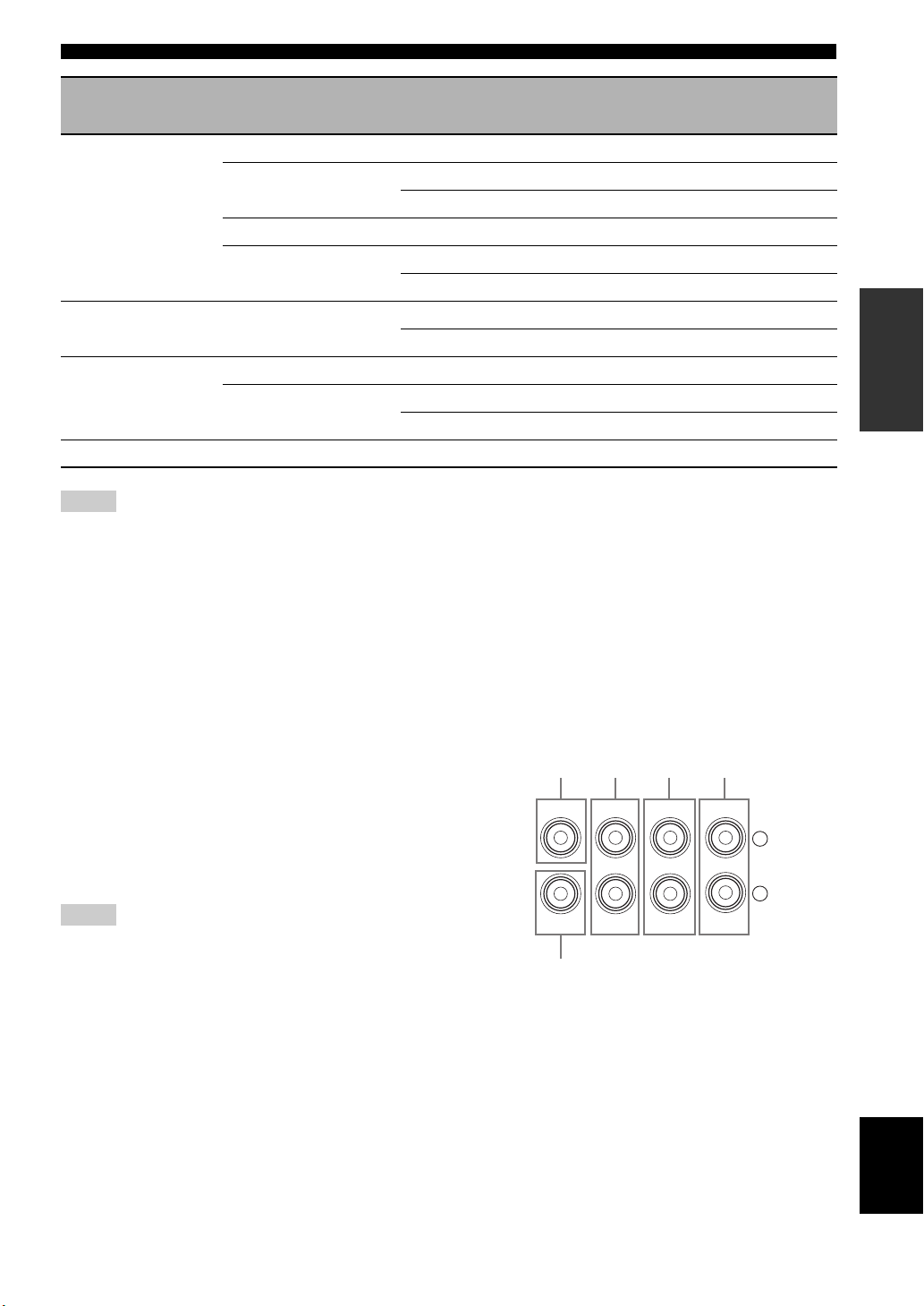
■ Connecting an external amplifier
This unit has more than enough power for any home use.
However, if you want to add more power to the speaker
output or if you want to use another amplifier, connect an
external amplifier to the PRE OUT jacks. Each PRE OUT
jack outputs the same channel signals as the
corresponding SPEAKERS terminals.
Notes
• When you make connections to the PRE OUT jacks, do not
make any connections to the SPEAKERS terminals.
• Adjust the volume level of the subwoofer with the control on
the subwoofer.
[1] [2]
CENTER
SUB
WOOFER
FRONT
[3] [4]
SURROUND
PRE OUT
[5]
[1] CENTER PRE OUT jack
Center channel output jack.
[2] FRONT PRE OUT jacks
Front channel output jacks.
[3] SURROUND PRE OUT jacks
Surround channel output jacks.
SINGLE(SB)
SUR.BACK/
PRESENCE
L
R
English
21 En
Connections
MULTI CH INPUT
SUB
WOOFER
SUB
CENTER
FRONT(6CH)
SURROUND
SB(8CH)
TAPE
MD/
(C)
()
R
L
R
L
[4] SUR.BACK/PRESENCE PRE OUT jacks
Surround back or presence channel output jacks. When
you only connect one external amplifier for the surround
back channel, connect it to the SINGLE (SB) jack.
y
• To output surround back channel signals at these jacks, set
“PRESENCE SP“ to “NONE” and “SUR.B L/R SP” to any
parameter except “NONE” (page 68).
• To output presence channel signals at these jacks, set
“PRESENCE SP“ to “YES” and “SUR.B L/R SP” to “NONE”
(page 68).
[5] SUBWOOFER PRE OUT jack
Connect a subwoofer with a built-in amplifier.
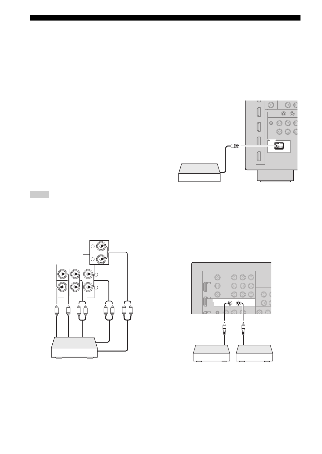
■ Connecting a multi-format player or an
external decoder
This unit is equipped with 6 additional input jacks
(FRONT L/R, CENTER, SURROUND L/R and
SUBWOOFER) for discrete multi-channel input from a
multi-format player, external decoder, etc. If you set
“INPUT CH” to “8ch” (page 75), the analog audio input
jacks assigned as “FRONT” can be used as the front
channel input jacks.
Notes
• When you select “MULTI CH” as the input source, the digital
sound field processor is automatically disabled.
• Since this unit does not redirect signals input at the MULTI CH
INPUT jacks to accommodate for missing speakers, connect at
least a 5.1-channel speaker system when using this feature.
*
■ Connecting a Yamaha iPod universal
dock or Bluetooth wireless audio
receiver
This unit is equipped with the DOCK terminal on the rear
panel that allows you to connect a Yamaha iPod universal
dock (such as YDS-11, sold separately) or Bluetooth
wireless audio receiver (such as YBA-10, sold separately).
Connect a Yamaha iPod universal dock or Bluetooth
receiver to the DOCK terminal on the rear panel of this
unit using its dedicated cable.
DOCK
Yamaha iPod universal dock or
Bluetooth wireless audio
receiver
■ Using REMOTE IN/OUT jacks
When the components are the Yamaha products and have
the capability of the transmission of the remote control
signals, connect the REMOTE IN and REMOTE OUT
jack to the remote control input and output jack with the
monaural analog mini cable as follows.
Subwoofer out
Center out
LR
Front out (6ch)
Surround back
out (8ch)
Surround out
LRLR
Multi-format player/
External decoder
* The analog audio input jacks assigned as “FRONT” in
“MULTI CH” (page 75).
22 En
OUT
IN
REMOTE
Front out (8ch)
Remote
control out
Infrared signal
receiver or
Yam ah a
component
Remote
control in
Yamah a
component
(CD or DVD
player, etc.)
Connections
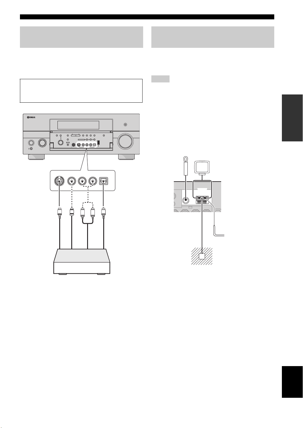
Using the VIDEO AUX jacks on the
front panel
Use the VIDEO AUX jacks on the front panel to connect a
game console or a video camera to this unit. To reproduce
the source signals input at these jacks, select “V-AUX” as
the input source.
Caution
Be sure to turn down the volume of this unit and other
components before making connections.
PURE DIRECT
SEARCH
AUDIO TONE
CONTROLSELECT
S VIDEO
ENTER PRESET/TUNING
STRAIGHT
EFFECT
SILENT CINEMA
YPAO
PROGRAM
OPTIMIZER
MIC
VIDEO
INPUT
MAIN ZONE
ON/OFF
ON
OFF
MASTER
STEREO/
INFO
BANDMODEMEMORY
MONO
ZONE ON/OFF ZONE CONTROLS
MULTI ZONE
ZONE 2
ZONE 3
RL
OPTICAL
AUDIO
S VIDEO
VIDEO
PHONES
VIDEO AUX
USB
AUDIO
OPTICAL
R
L
VOLUME
Connecting the FM and AM
antennas
Both FM and AM indoor antennas are supplied with this
unit. In general, these antennas should provide sufficient
signal strength.
Notes
• The types of the supplied antennas and the FM antenna terminal
of this unit are different depending on the models.
• (Asia and General models only) Be sure to set the tuner
frequency step according to the frequency spacing in your area
(page 94).
• The AM loop antenna should be placed away from this unit.
• The AM loop antenna should always be connected, even if an
outdoor AM antenna is connected to this unit.
• If you experience poor reception quality, install an outdoor
antenna. Consult the nearest authorized Yamaha dealer or
service center about outdoor antennas.
Indoor FM
antenna
(supplied)
FM
75Ω UNBAL.
ANTENNA
GND
AM loop
antenna
(supplied)
AM
PREPARATION
V
S
S-Video output
L
Video output
Game console or
video camera
O
R
Optical output
output
Audio
Outdoor AM antenna
Use a 5 to 10 m (16 to 33 ft)
vinyl-covered wire extended
outdoors from a window.
Ground (GND terminal)
For maximum safety and minimum
interference, connect the antenna GND
terminal to a good earth ground. A good
earth ground is a metal stake driven into
moist earth.
English
23 En
Connections
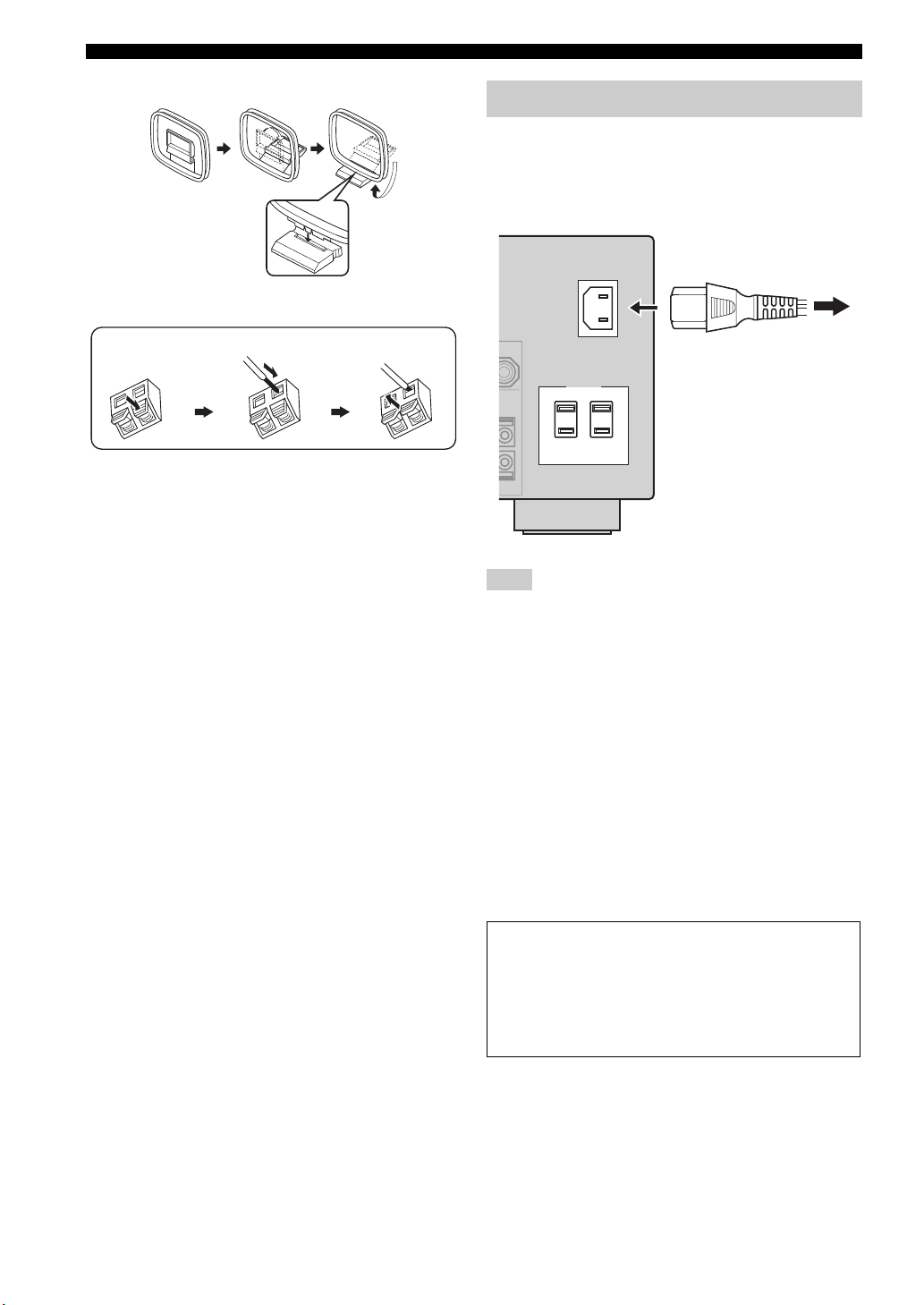
Assembling the supplied AM loop antenna
Connecting the wire of the AM loop antenna
Connecting the power cable
■ Connecting the AC power cable
Plug the supplied AC power cable into the AC inlet after
all other connections are complete, then plug the AC
power cable into an AC wall outlet.
AC IN
Press and hold
Insert
Release
y
The wire of the AM loop antenna does not have any polarity
and you can connect either end of the wire to AM or GND
terminal.
To the AC wall outlet
AC OUTLETS
Note
(Asia model only) Select one of the supplied power cables
suitable for the type of AC wall outlet in your location before
plugging this unit into the AC wall outlet.
■ AC OUTLET(S) (SWITCHED)
U.K. and Australia models..................................... 1 outlet
Korea model............................................................... None
Other models......................................................... 2 outlets
Use these outlet(s) to supply power to any connected
components. Connect the power cable of your other
components to these outlet(s). Power to these outlet(s) is
supplied when this unit is turned on. However, power to
these outlet(s) is cut off when this unit is turned off. For
information on the maximum power or the total power
consumption of the components that can be connected to
these outlet(s), see “Specifications” (page 112).
24 En
Memory back-up
The memory back-up circuit prevents the stored data
from being lost even if this unit is in the standby mode.
However, the stored data will be lost in case the power
cable is disconnected from the AC wall outlet or if the
power supply is cut off for more than one week.
Connections
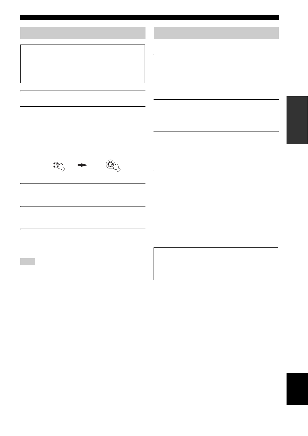
Setting the speaker impedance
Caution
If you are to use 6 ohm speakers, set “SPEAKER
IMP.” to “6Ω MIN” as follows BEFORE using this
unit. You can also use 4 ohm speakers as the front
speakers (page 93).
1 Make sure this unit is turned off.
2 Press and hold
panel and then press AMASTER ON/OFF
inward to the ON position.
This unit turns on, and the advanced setup menu
appears in the front panel display.
STRAIGHT
3 Rotate the
“SPEAKER IMP.”.
4 Press
5 Press
Note
The setting you made is reflected next time you turn on this
unit.
O
“6Ω MIN”.
A
outward to the OFF position to save the new
setting and turn off this unit.
O
STRAIGHT on the front
While holding
down
EFFECT
N
PROGRAM selector to select
STRAIGHT repeatedly to select
MASTER ON/OFF to release it
MASTER
Turning this unit on and off
■ Turning on this unit
Press AMASTER ON/OFF on the front panel
inward to the ON position.
When you turn on this unit by pressing AMASTER ON/
OFF, the main zone is turned on.
■ Turning off this unit
Press AMASTER ON/OFF on the front panel
again to release it outward to the OFF position.
■ Set the main zone to the standby mode
B
Press
(or
MAIN ZONE ON/OFF
C
STANDBY
).
■ Turning on the main zone from the
standby mode
Press BMAIN ZONE ON/OFF (or DPOWER).
y
• Basically, we recommend that you use the standby mode to turn
off this unit. In the standby mode, this unit consumes a small
amount of power in order to receive infrared signals from the
remote control.
• BMAIN ZONE ON/OFF, CSTANDBY and DPOWER are
operational only when AMASTER ON/OFF is pressed inward
to the ON position.
• When you turn on this unit, there will be a delay for a few
seconds before this unit can reproduce sound.
If there are some problems...
• First, turn off and then turn on this unit again.
• If problems persist, initialize the parameters of this
unit (page 105).
PREPARATION
25 En
English
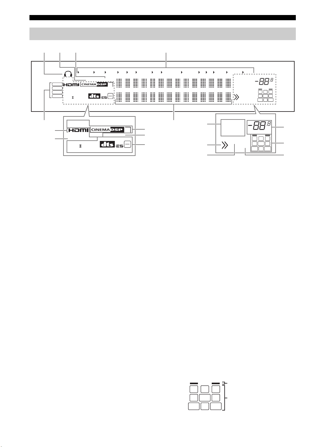
Connections
q
n
Front panel display
ba c d
USB
DSD
PCM
WMA
MP3
SILENT
CINEMA
ENHANCER
q
DIGITAL PLUS
q
PL x
q
TRUE HD
YPAO PRESET
VIRTUAL ADAPTIVE DRC
DISCRETE
q
EX
MASTER AUDIO
DOCK V- AUX VCR DVR CBL/SAT DVD BD/HD DVD MD/CD-R TV CD PHONO MULTI CH TUNER
TUNED STEREO
AUTO MEMORY
PTY HOLD EON
SLEEP
ZONE2
ZONE3
HD
MATRIX
96
24
3
dB
VOLUME
L C R
SL LFE SR
SBL SB SBR
e
g
h
SILENT
CINEMA
ENHANCER
q
DIGITAL PLUS
q
PL x
q
TRUE HD
VIRTUAL ADAPTIVE DRC
DISCRETE
q
EX
MASTER AUDIO
MATRIX
HD
3
i
j
96
24
k
a Headphones indicator
Lights up when headphones are connected (page 35).
b YPAO indicator
Lights up when you run “AUTO SETUP” and when the
speaker settings set in “AUTO SETUP” are used without
any modifications (page 29).
c PRESET indicator
Lights up while this unit is in the preset tuning mode.
d Input source indicators
The corresponding cursor lights up to show the currently
selected input source.
e Input signal indicators
Lights up when this unit is reproducing DSD (Direct
Stream Digital), PCM (Pulse Code Modulation), WMA
(Windows Media Audio), or MP3 (MPEG-1 Audio
Layer-3) audio signals.
f Multi-information display
Shows the name of the current sound field program and
other information when adjusting or changing settings.
g HDMI indicator
Lights up when the signal of the selected input source is
input at one of the HDMI input jacks (page 16).
h ENHANCER indicator
Lights up when the Compressed Music Enhancer mode is
turned on (page 43).
i DSP indicators
The respective indicator lights up when any of the sound
field programs are selected.
SILENT CINEMA indicator
Lights up when headphones are connected and a
sound field program is selected (page 43).
f
l
m
TUNED STEREO
AUTO MEMORY
PTY HOLD EON
ZONE2
SLEEP
ZONE3
dB
VOLUME
L C R
SL LFE SR
SBL SB SBR
o
p
CINEMA DSP indicator
Lights up when you select a CINEMA DSP sound
field program (page 38).
3D indicator
Lights up when the CINEMA DSP 3D mode is turned
on (page 44).
VIRTUAL indicator
Lights up when Virtual CINEMA DSP is active (see
page 43).
j ADAPTIVE DRC indicator
Lights up when the adaptive dynamic range control
feature is turned on (page 69).
k Decoder indicators
The respective indicator lights up when any of the
decoders of this unit function.
l Tuner indicators
Light up when this unit is in the FM or AM tuning mode.
m Menu browsing indicator
Lights up if any items exist under the current item during
menu browsing for iPod and USB.
n SLEEP indicator
Lights up while the sleep timer is on (page 37).
o VOLUME level indicator
• Indicates the current volume level.
• Flashes while the mute function is on (page 36).
p Input channel and speaker indicators
Presence speaker indicators
L C R
SL LFE SR
Input channel indicators
SBL SB SBR
26 En
 Loading...