

Page 1

RX-V1700
AV Receive r
AB
OWNER’S MANUAL
Page 2

CAUTION: READ THIS BEFORE OPERATING YOUR UNIT.
CAUTION: READ THIS BEFORE OPERATING YOUR UNIT.
1 To assure the finest performance, please read this manual
carefully. Keep it in a safe place for future reference.
2 Install this sound system in a well ventilated, cool, dry, clean
place – away from direct sunlight, heat sources, vibration,
dust, moisture, and/or cold. Allow ventilation space of at least
30 cm on the top, 20 cm on the left and right, and 20 cm on
the back of this unit.
3 Locate this unit away from other electrical appliances, motors,
or transformers to avoid humming sounds.
4 Do not expose this unit to sudden temperature changes from
cold to hot, and do not locate this unit in an environment with
high humidity (i.e. a room with a humidifier) to prevent
condensation inside this unit, which may cause an electrical
shock, fire, damage to this unit, and/or personal injury.
5 Avoid installing this unit where foreign objects may fall onto
this unit and/or this unit may be exposed to liquid dripping or
splashing. On the top of this unit, do not place:
– Other components, as they may cause damage and/or
discoloration on the surface of this unit.
– Burning objects (i.e. candles), as they may cause fire,
damage to this unit, and/or personal injury.
– Containers with liquid in them, as they may fall and liquid
may cause electrical shock to the user and/or damage to
this unit.
6 Do not cover this unit with a newspaper, tablecloth, curtain,
etc. in order not to obstruct heat radiation. If the temperature
inside this unit rises, it may cause fire, damage to this unit,
and/or personal injury.
7 Do not plug in this unit to a wall outlet until all connections
are complete.
8 Do not operate this unit upside-down. It may overheat,
possibly causing damage.
9 Do not use force on switches, knobs and/or cords.
10 When disconnecting the power cable from the wall outlet,
grasp the plug; do not pull the cable.
11 Do not clean this unit with chemical solvents; this might
damage the finish. Use a clean, dry cloth.
12 Only voltage specified on this unit must be used. Using this
unit with a higher voltage than specified is dangerous and may
cause fire, damage to this unit, and/or personal injury.
YAMAHA will not be held responsible for any damage
resulting from use of this unit with a voltage other than
specified.
13 To prevent damage by lightning, keep the power cord and
outdoor antennas disconnected from a wall outlet or the unit
during a lightning storm.
14 Do not attempt to modify or fix this unit. Contact qualified
YAMAHA service personnel when any service is needed. The
cabinet should never be opened for any reasons.
15 When not planning to use this unit for long periods of time
(i.e. vacation), disconnect the AC power plug from the wall
outlet.
16 Install this unit near the AC outlet and where the AC power
plug can be reached easily.
17 Be sure to read the “TROUBLESHOOTING” section on
common operating errors before concluding that this unit is
faulty.
18 Before moving this unit, press MASTER ON/OFF to release it
outward to the OFF position to turn off this unit, the main
room, Zone 2 and Zone 3 and then disconnect the AC power
plug from the AC wall outlet.
19 VOLTAGE SELECTOR (Asia and General models only)
The VOLTAGE SELECTOR on the rear panel of this unit
must be set for your local main voltage BEFORE plugging
into the AC main supply. Voltages are:
Asia model ................................ AC 220/230–240 V, 50/60 Hz
General model .............AC 110/120/220/230–240 V, 50/60 Hz
WAR NING
TO REDUCE THE RISK OF FIRE OR ELECTRIC
SHOCK, DO NOT EXPOSE THIS UNIT TO RAIN
OR MOISTURE.
As long as this unit is connected to the AC wall outlet,
it is not disconnected from the AC power source even
if you turn off this unit by MASTER ON/OFF. In this
state, this unit is designed to consume a very small
quantity of power.
■ For U.K. customers
If the socket outlets in the home are not suitable for the
plug supplied with this appliance, it should be cut off and
an appropriate 3 pin plug fitted. For details, refer to the
instructions described below.
Note
The plug severed from the mains lead must be destroyed, as a
plug with bared flexible cord is hazardous if engaged in a live
socket outlet.
■ Special Instructions for U.K. Model
IMPORTANT
THE WIRES IN MAINS LEAD ARE COLOURED IN
ACCORDANCE WITH THE FOLLOWING CODE:
Blue: NEUTRAL
Brown: LIVE
As the colours of the wires in the mains lead of this
apparatus may not correspond with the coloured
markings identifying the terminals in your plug,
proceed as follows:
The wire which is coloured BLUE must be connected
to the terminal which is marked with the letter N or
coloured BLACK. The wire which is coloured
BROWN must be connected to the terminal which is
marked with the letter L or coloured RED.
Making sure that neither core is connected to the earth
terminal of the three pin plug.
Page 3

CONTENTS
INTRODUCTION
FEATURES ............................................................. 2
GETTING STARTED............................................ 3
Supplied accessories .................................................. 3
CONTROLS AND FUNCTIONS ......................... 4
Front panel ................................................................. 4
Remote control........................................................... 6
Zone 2/Zone 3 remote control ................................... 8
Preparing the remote control ..................................... 9
Front panel display .................................................. 10
Rear panel ................................................................ 12
PREPARATION
CONNECTIONS .................................................. 13
Placing speakers....................................................... 13
Connecting speakers ................................................ 14
Using bi-amplification connections ......................... 17
Information on jacks and cable plugs ...................... 18
Information on HDMI.............................................. 19
Audio and video signal flow .................................... 20
Connecting a TV monitor or projector .................... 21
Connecting other components ................................. 22
Connecting a multi-format player
or an external decoder ......................................... 26
Connecting a YAMAHA iPod universal dock ........27
Using the VIDEO AUX jacks on the front panel .... 27
Connecting the FM and AM antennas ..................... 28
Connecting the power cable..................................... 29
Setting the speaker impedance................................. 30
Turning on and off the power .................................. 31
AUTO SETUP....................................................... 32
Using AUTO SETUP .............................................. 32
BASIC OPERATION
PLAYBACK.......................................................... 38
Basic procedure ....................................................... 38
Selecting audio input jacks (AUDIO SELECT) ...... 40
Selecting the MULTI CH INPUT component ......... 41
Using your headphones............................................ 41
Muting the audio output........................................... 41
Displaying the input source information ................. 42
Playing video sources
in the background of an audio source .................. 43
Using the sleep timer ............................................... 43
SOUND FIELD PROGRAMS............................. 44
Selecting sound field programs ............................... 44
Sound field program descriptions ............................ 45
Enjoying unprocessed input sources........................ 49
USING AUDIO FEATURES ............................... 50
Enjoying pure hi-fi sound ........................................ 50
Adjusting the tonal quality....................................... 50
Adjusting the speaker level...................................... 51
Enjoying multi-channel sources in 2-channel stereo51
Selecting the Compressed Music Enhancer mode... 52
Selecting the night listening mode........................... 53
FM/AM TUNING ..................................................54
FM/AM controls and functions ............................... 54
Automatic tuning ..................................................... 56
Manual tuning .......................................................... 57
Automatic preset tuning........................................... 58
Manual preset tuning ............................................... 59
Selecting preset stations........................................... 60
Exchanging preset stations ...................................... 61
RADIO DATA SYSTEM TUNING
(U.K. AND EUROPE MODELS ONLY)........62
Displaying the Radio Data System information ...... 62
Selecting the Radio Data System program type
(PTY SEEK mode) .............................................. 63
Using the enhanced other networks (EON)
data service .......................................................... 64
USING iPod ...........................................................66
Controlling iPod ...................................................... 66
RECORDING ........................................................68
ADVANCED OPERATION
ADVANCED SOUND CONFIGURATIONS .....69
Changing sound field parameter settings................. 69
Selecting decoders ................................................... 73
CUSTOMIZING THIS UNIT
(MANUAL SETUP) ..........................................77
Using SET MENU ................................................... 79
1 BASIC MENU...................................................... 80
2 SOUND MENU.................................................... 84
3 INPUT MENU...................................................... 87
4 OPTION MENU................................................... 90
REMOTE CONTROL FEATURES ...................94
Controlling this unit, a TV,
or other components ............................................ 94
Setting remote control codes ................................... 96
Programming codes from other remote controls ..... 98
Changing source names in the display window....... 99
Macro programming features ................................ 100
Clearing configurations ......................................... 103
USING MULTI-ZONE CONFIGURATION ...106
Connecting the Zone 2 and Zone 3 components ... 106
Controlling Zone 2 or Zone 3 ................................ 107
ADVANCED SETUP ..........................................110
Using ADVANCED SETUP ................................. 110
Setting remote control ID ...................................... 112
TROUBLESHOOTING .....................................115
ADDITIONAL INFORMATION
RESETTING THE SYSTEM.............................122
GLOSSARY.........................................................123
SOUND FIELD PROGRAM
INFORMATION .............................................126
PARAMETRIC EQUALIZER
INFORMATION .............................................127
SPECIFICATIONS.............................................128
APPENDIX (at the end of this manual)
• SOUND OUTPUT IN EACH SOUND FIELD PROGRAM
• LIST OF REMOTE CONTROL CODES
PREPARATIONINTRODUCTION
OPERATION
BASIC
OPERATION
ADVANCED
INFORMATION
ADDITIONAL
English
1 En
Page 4

FEATURES
FEATURES
Built-in 7-channel power amplifier
◆ Minimum RMS output power
(20 Hz to 20 kHz, 0.04% THD, 8 Ω)
Front: 130 W + 130 W
Center: 130 W
Surround: 130 W + 130 W
Surround back: 130 W + 130 W
Sound field programs
◆ Proprietary YAMAHA technology for the creation of sound
fields
◆ Dolby Digital/Dolby Digital EX decoder
◆ DTS/DTS-ES Matrix 6.1, Discrete 6.1, DTS Neo:6,
DTS 96/24 decoder
◆ Dolby Pro Logic/Dolby Pro Logic II/Dolby Pro Logic IIx
decoder
◆ Virtual CINEMA DSP
◆ SILENT CINEMA
Sophisticated AM/FM tuner
◆ 40-station random and direct preset tuning
◆ Automatic preset tuning
◆ Preset station shifting capability (preset editing)
◆ Radio Data System capability (U.K. and Europe models only)
HDMI (High-Definition Multimedia Interface)
◆ HDMI interface for standard, enhanced or
high-definition video (includes 1080p video signal
transmission) as well as multi-channel digital audio based on
HDMI version 1.2a
◆ Analog video to HDMI digital video up-conversion
(composite video ↔ S-video ↔ component video → HDMI
digital video) capability for monitor out
iPod controlling capability
◆ DOCK terminal to connect a YAMAHA iPod universal dock
(such as the YDS-10, sold separately), which supports iPod
(Click and Wheel), iPod nano, and iPod mini
Other features
◆ YPAO (YAMAHA Parametric Room Acoustic Optimizer) for
automatic speaker setup
◆ 192-kHz/24-bit D/A converter
◆ OSD (on-screen display) menus that allow you to optimize
this unit to suit your individual audiovisual system
◆ 6 or 8-channel additional input jacks for discrete multi-
channel input
◆ Analog video interlace/progressive conversion from 480i
(NTSC)/576i (PAL) to 480p/576p
◆ S-video signal input/output capability
◆ Component video input/output capability includes (3
COMPONENT VIDEO INs and 1 MONITOR OUT)
◆ Optical and coaxial digital audio signal jacks
◆ Pure Direct mode for pure hi-fi sound for all sources
◆ Cinema and music night listening modes
◆ Compressed Music Enhancer mode to improve the sound
quality of compression artifacts (such as the MP3 format) to
that of a high-quality stereo
◆ Remote control with preset remote control codes, learning and
macro capability
◆ ZONE 2/ZONE 3 custom installation facility
◆ Zone switching capability between the main zone and
ZONE 2/ZONE 3 using ZONE CONTROLS
◆ Sleep timer
Manufactured under license from Dolby Laboratories.
“Dolby”, “Pro Logic”, and the double-D symbol are trademarks
of Dolby Laboratories.
Manufactured under license from Digital Theater Systems, Inc.
“DTS”, “DTS-ES”, “NEO:6”, and “DTS 96/24” are trademarks
of Digital Theater Systems, Inc. Copyright 1996, 2003 Digital
Theater Systems, Inc. All right reserved.
®
iPod
“iPod” is a trademark of Apple Computer, Inc., registered in the
U.S. and other countries.
2 En
“HDMI”, the “HDMI” logo and “High-Definition Multimedia
Interface” are trademarks or registered trademarks of HDMI
Licensing LLC.
“SILENT CINEMA” is a trademark of YAMAHA
CORPORATION.
Page 5
GETTING STARTED
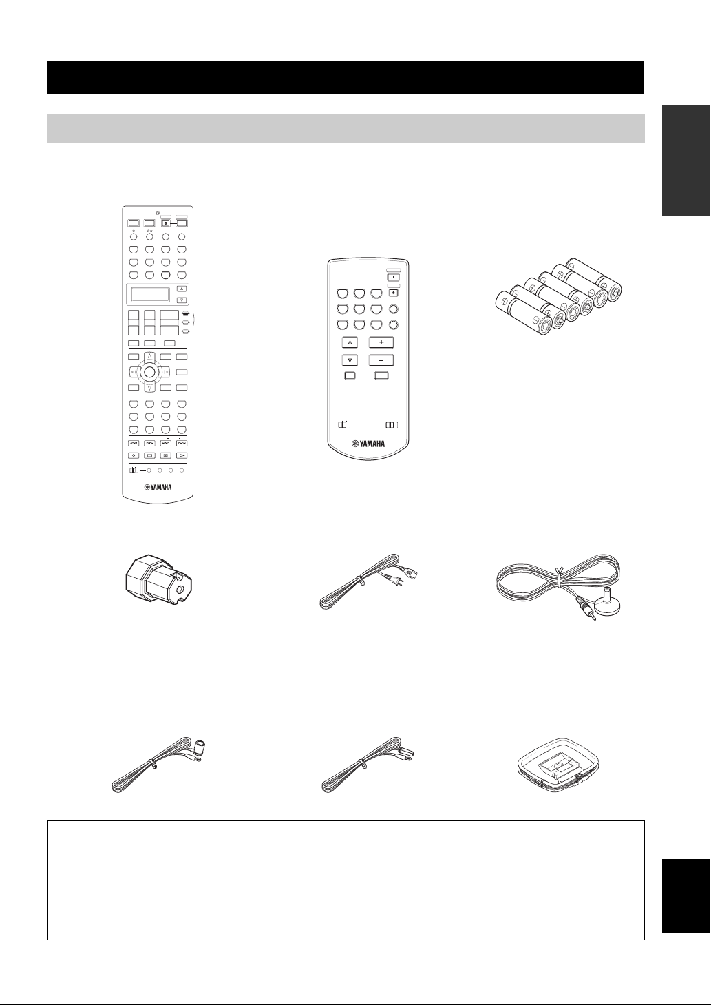
Supplied accessories
Check that you received all of the following parts.
Remote control
POWER
POWER
POWER
STANDBY
AV
A/B/C/D/E
PHONO
V-AUX/DOCK
TV VOL
TV MUTE
LEVEL
TITLE
B
RETURN
CLASSICAL
STEREO
FREQ/TEXT
DISC SKIP
OFF
TV
DTV
+
–
D
N
A
1
5
9
REC
ON
TUNER CD
CBL/SAT
VCR 1
+
CH
TV INPUT
PRESET/CH
ENTER
LIVE/CLUB
2
SUR. DECODE
6
0
EON
MACRO
AUDIO SEL
MD/TAPE
DVR/VCR 2
SET MENU
MENU
SRCH MODE
PARAMETER
DISPLAY
ENTERTAIN
SELECT
NIGHT
+
MODE PTY SEEK
LEARN
VOLUME
3
7
10
SLEEP
MULTI CH IN
CD-R
DVD
SELECT
AMP
+
SOURCE
TV
––
MUTE
PURE DIRECT
AUDIO
STRAIGHT
EFFECT
MOVIE
4
EXTD SUR.
8
ENHANCER
ENT
START
CLEAR
RENAME
Zone 2/Zone 3
remote control
(except Europe model)
POWER
CBL/SAT
DVR/VCR 2
STANDBY
CD
CD-R
PHONO
MD/TAPE
DVD
V-AUX/DOCK
VOLUME
MUTE
ZONE 3
ZONE 2
TUNER
ID1
DTV
VCR 1
PRESET
A/B/C/D/E
ID2
GETTING STARTED
INTRODUCTION
Batteries (6)
(AAA, R03, UM-4)
Optimizer microphoneSpeaker terminal wrench Power cable
Indoor FM antenna
(U.S.A., Canada, China, Asia,
(Europe, U.K. and Australia models)
Indoor FM antenna
AM loop antenna
General and Korea models)
About this manual
• y indicates a tip for your operation.
• Some operations can be performed by using either the buttons on the front panel or the ones on the remote control. In case the
button names differ between the front panel and the remote control, the button name on the remote control is given in
parentheses.
• This manual is printed prior to production. Design and specifications are subject to change in part as a result of improvements,
etc. In case of differences between the manual and product, the product has priority.
English
3 En
Page 6
CONTROLS AND FUNCTIONS
CONTROLS AND FUNCTIONS
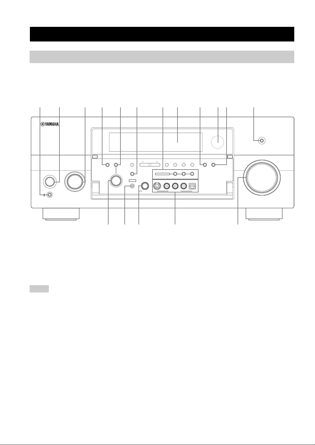
Front panel
This section describes only the amplifier controls and functions of this unit. See the following pages for details about
other control and functions.
• AM/FM tuning ........................... see page 54
32 BA09
AUDIO
TONE
CONTROL
SELECT
INPUT
PROGRAM
ON
OFF
MAIN ZONE
ON/OFF
MASTER
1 MASTER ON/OFF
Turns this unit on or off (see page 31).
2 MAIN ZONE ON/OFF
Turns on the main zone or sets it to the standby mode
(see page 31).
Notes
• In the standby mode, this unit consumes a small amount of
power in order to receive infrared signals from the remote
control.
• When you turn on this unit, there will be a 4 to 5-second delay
before this unit can reproduce sound.
• This button is operational only when MASTER ON/OFF is
pressed inward to the ON position.
3 INPUT selector
Selects the desired input source (see page 38).
A/B/C/D/E
STRAIGHT
EFFECT
YPAO
OPTIMIZER
MIC
PRESET/TUNING
SILENT CINEMA
PHONES
876541
PURE DIRECT
VOLUME
MEMORY
MULTI ZONE
S VIDEO
PRESET/
TUNING
EDIT
VIDEO
VIDEO AUX
FM/AM
ZONE 2
ZONE ON/OFF
L
AUDIO
MAN'L/AUTO FM
ZONE 3
R
TUNING
MODE
ZONE CONTROLS
OPTICAL
ENHANCER
NIGHT
GFEDC
4 AUDIO SELECT
Toggles the priority for the type of audio input jack
between “AUTO”, “HDMI”, “COAX/OPT” and
“ANALOG” when one component is connected to two or
more input jacks (see page 40).
5 TONE CONTROL
Adjusts the bass/treble balance of the front left, front right
and center channels in conjunction with the PROGRAM
selector (see page 50).
6 STRAIGHT
Turns the sound field programs off or on. When the
“STRAIGHT” mode is selected, 2-channel or multichannel input signals are output directly from their
respective speakers without effect processing (see
page 49).
4 En
Page 7
CONTROLS AND FUNCTIONS
7 MULTI ZONE buttons
ZONE 2 ON/OFF
Turns on Zone 2 only or sets it to the standby mode.
See page 107 for details.
ZONE 3 ON/OFF
Turns on Zone 3 only or sets it to the standby mode.
See page 107 for details.
Note
These buttons are operational only when MASTER ON/OFF
is pressed inward to the ON position.
ZONE CONTROLS
Switches the zone you want to control between the
main zone, Zone 2 and Zone 3. See page 107 for
details.
y
After you press ZONE CONTROLS, the indicator for the
currently selected zone flashes in the front panel display for
approximately 5 seconds. While the indicator is flashing,
perform the desired operation.
8 Front panel display
Shows information about the operational status of this unit
(see page 10).
9 ENHANCER
Turns on or off the Compressed Music Enhancer mode
(see page 52).
0 Remote control sensor
Receives signals from the remote control (see page 9).
A NIGHT
Turns on or off the night listening modes (see page 53).
B PURE DIRECT
Turns on or off the Pure Direct mode (see page 50).
C PROGRAM selector
• Selects sound field programs (see page 44).
• Adjusts the bass/treble balance in conjunction with
TONE CONTROL (see page 50).
D OPTIMIZER MIC jack
Use to connect and input audio signals from the supplied
optimizer microphone in the “AUTO SETUP” procedure
(see page 32).
E PHONES jack
Outputs audio signals for private listening with
headphones (see page 41).
F VIDEO AUX jacks
Input audio and video signals from a portable external
source such as a game console or a video camera
(see page 27).
y
To reproduce the source signals input at these jacks, select
“V-AUX” as the input source.
Note
The audio signals input at the DOCK terminal on the rear panel
take priority over the ones input at the VIDEO AUX jacks.
G VOLUME
Controls the output level of all audio channels.
y
This does not affect the AUDIO OUT (REC) level.
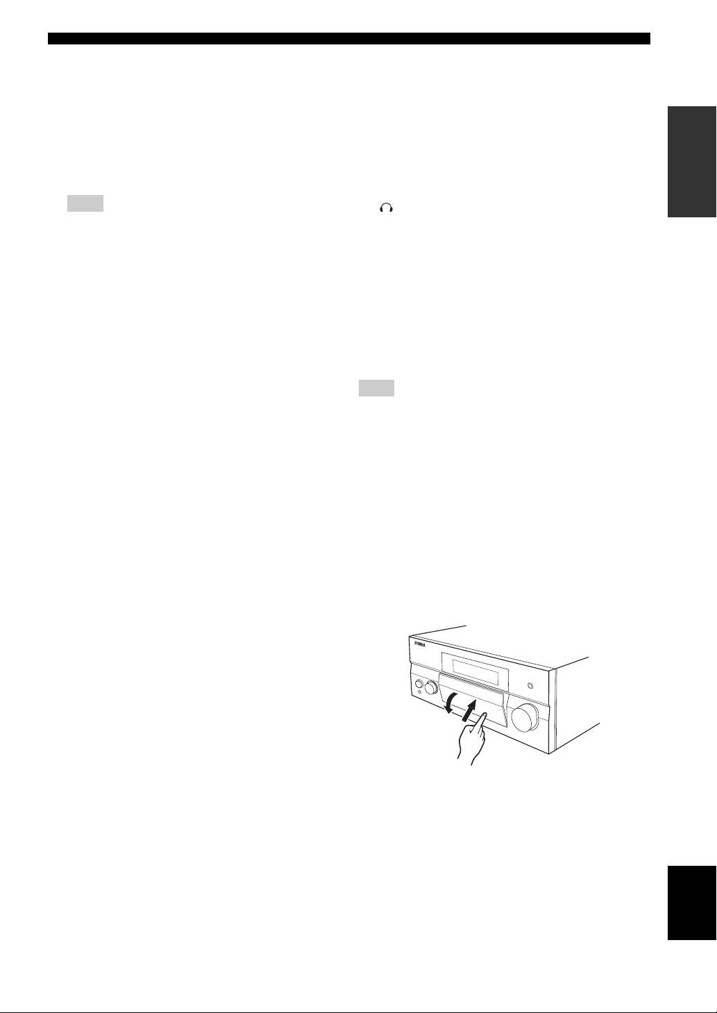
■ Opening and closing the front panel
door
When you want to use the controls behind the front panel
door, open the door by gently pressing on the lower part of
the panel. Keep the door closed when not using these
controls.
INTRODUCTION
To open, press gently on the lower part of the panel.
English
5 En
Page 8
CONTROLS AND FUNCTIONS
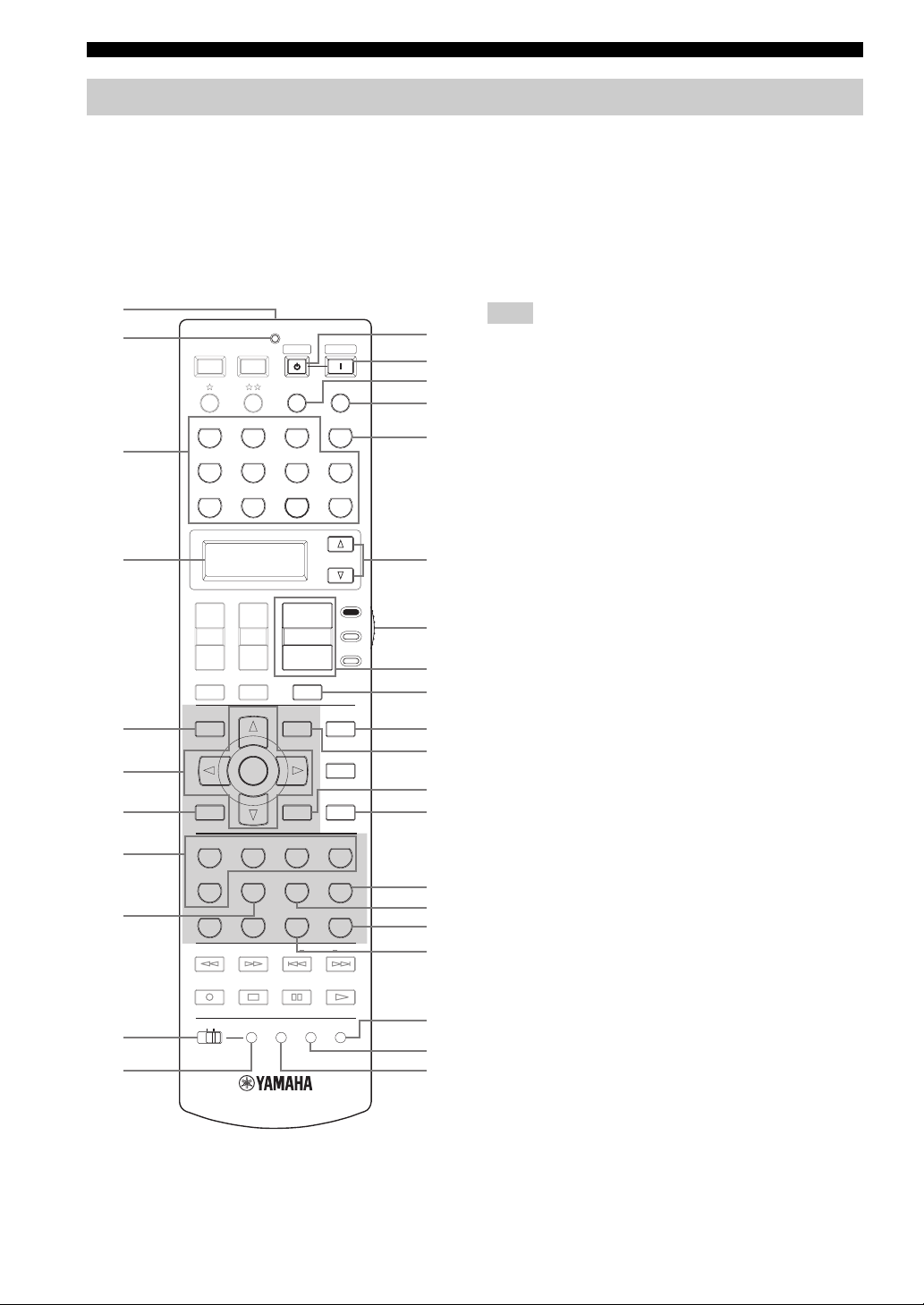
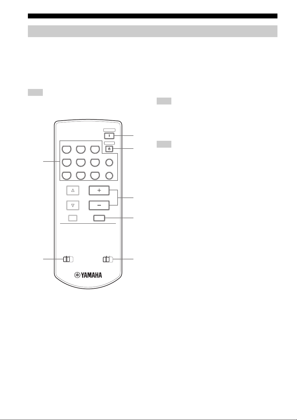
Remote control
■ Remote control controls and functions
This section describes only the amplifier controls and functions of this unit. See the following pages for details about
other control and functions.
• AM/FM tuning ........................................ see page 54
• Controlling a TV ..................................... see page 94
• Controlling other components ................. see page 95
• Controlling option components ............... see page 96
1
2
3
4
5
6
7
8
9
0
A
POWER
TV
PHONO
V-AUX/DOCK
DTV
+
TV VOL
–
TV MUTE
LEVEL
TITLE
A
B
A/B/C/D/E
RETURN
CLASSICAL
1
STEREO
5
9
FREQ/TEXT
REC
DISC SKIP
OFF
ND
ON
POWER
AV
TUNER CD
CBL/SAT
VCR 1
+
CH
TV INPUT
PRESET/CH
ENTER
LIVE/CLUB
2
SUR. DECODE
6
0
EON
LEARN
MACRO
STANDBY
AUDIO SEL
MD/TAPE
DVR/VCR 2
+
VOLU ME
––
MUTE
SET MENU
MENU
SRCH MODE
PARAMETER
DISPLAY
ENTERTAIN
3
SELECT
7
NIGHT
+
10
MODE PTY SEEK
CLEAR
POWER
SLEEP
MULTI CH IN
CD-R
DVD
SELECT
AMP
SOURCE
TV
PURE DIRECT
AUDIO
STRAIGHT
EFFECT
MOVIE
4
EXTD SUR.
8
ENHANCER
ENT
START
RENAME
B
C
D
E
F
G
H
I
J
K
L
M
N
O
P
Q
R
S
t
U
Note
The operation mode of the remote control buttons in the shaded
area below depends on the operation mode selector position. Set
the operation mode selector to AMP to control this unit.
1 Infrared window
Outputs infrared control signals. Aim this window at the
component you want to operate (see page 9).
2 TRANSMIT indicator
Flashes while the remote control is sending infrared
signals.
3 Input selector buttons
Select the input source you want to control.
y
The selected input source name appears in the display window on
the remote control showing which source is currently operational.
4 Display window
Shows the name of the selected input source that you can
control.
5 LEVEL
Selects the speaker channel to be adjusted and sets the
output level (see page 51).
6 Cursor buttons k / n / l / h, ENTER
Select and adjust the sound field program parameters or
the “SET MENU” parameters.
7 RETURN
Returns to the previous menu level when adjusting the
“SET MENU” parameters.
8 Sound field program selector buttons
Select sound field programs (see page 44).
9 SUR. DECODE
Activates decoders to play back 2-channel sources in
surround (see page 73).
6 En
Page 9

CONTROLS AND FUNCTIONS
0 MACRO ON/OFF
Turns on or off the macro function (see page 100).
A MACRO
Programs a series of operations to be controlled with a
single button (see page 100).
B STANDBY
Sets the main zone to the standby mode (see page 31).
Note
This button is operational only when MASTER ON/OFF on the
front panel is pressed inward to the ON position.
C POWER
Turns on the main zone (see page 31).
Note
This button is operational only when MASTER ON/OFF on the
front panel is pressed inward to the ON position.
D AUDIO SEL
Toggles the priority for the type of audio input jack
between “AUTO”, “HDMI”, “COAX/OPT” and
“ANALOG” when one component is connected to two or
more input jacks (see page 40).
E SLEEP
Sets the sleep timer (see page 43).
F MULTI CH IN
Selects the component connected to the MULTI CH
INPUT jacks as the input source when using an external
decoder, etc. (see page 41).
G SELECT k / n
Selects another input source that you can control
independently of the input source selected with the input
selector buttons.
H Operation mode selector
Selects the operation mode of the remote control buttons
in the shaded area.
AMP
Operates the amplifier function of this unit.
SOURCE
Operates the component selected with an input
selector button (see page 95).
TV
Operates the TV assigned to either DTV or PHONO
(see page 94).
I VOLUME +/–
Increases or decreases the volume level.
J MUTE
Mutes the audio output. Press again to restore the audio
output to the previous volume level (see page 41).
K PURE DIRECT
Turns on or off the pure direct mode (see page 50).
L SET MENU
Enters “SET MENU” (see page 79).
M PAR AM ET ER
Displays sound field parameter settings in the on-screen
display (OSD) (see page 69).
N STRAIGHT
Turns the sound field programs off or on. When the
“STRAIGHT” mode is selected, 2-channel or multichannel input signals are output directly from their
respective speakers without effect processing (see
page 49).
O EXTD SUR.
Switches between 5.1 and 6.1/7.1-channel playback of
multi-channel sources (see page 73).
P SELECT
Selects decoders for 2-channel sources (see pages 73 and
75).
Q ENHANCER
Turns on or off the Compressed Music Enhancer mode
(see page 52).
R NIGHT
Turns on or off the night listening modes (see page 53).
S RENAME
Changes the name of the input source in the display
window (see page 99).
T CLEAR
Clears remote control functions acquired from the learn,
macro and/or rename features (see page 103).
U LEARN
Programs remote control codes of functions from other
remote controls (see page 98).
INTRODUCTION
Notes
• To set the remote control codes for other components, see
page 96.
• When you set the remote control codes for both DTV and
PHONO (see page 96), priority is given to the one set for
DTV.
English
7 En
Page 10
CONTROLS AND FUNCTIONS
Zone 2/Zone 3 remote control
This section describes the function of each control on the
Zone 2/Zone 3 remote control used to control the amplifier
functions of Zone 2 or Zone 3.
See the following pages for details about other controls
and functions.
• AM/FM tuning ........................................ see page 54
Note
Zone 2/Zone 3 remote control is supplied with U.S.A., Canada,
Australia, U.K., China, Asia and General models only.
POWER
3
TUNER
CD
CD-R
STANDBY
4
DTV
CBL/SAT
MD/TAPE
PHONO
1
VCR 1
PRESET
A/B/C/D/E
DVR/VCR 2
DVD
VOLUME
MUTE
V-AUX/DOCK
5
6
1 Input selector buttons
Select the desired input source of Zone 2 or Zone 3.
2 ID1/ID2 switch
Switches the remote control ID between ID1 and ID2
(see page 97).
3 POWER
Turns on Zone 2 or Zone 3.
Note
This button is operational only when MASTER ON/OFF on the
front panel is pressed inward to the ON position.
4 STANDBY
Sets Zone 2 or Zone 3 to the standby mode.
Note
This button is operational only when MASTER ON/OFF on the
front panel is pressed inward to the ON position.
5 VO LUME +/–
Increases or decreases the volume level of Zone 2 or
Zone 3.
6 MUTE
Mutes the sound of Zone 2 or Zone 3. Press again to
restore the audio output to the previous volume level.
7 ZONE 2/ZONE 3 switch
Switches between the operation mode of Zone 2 and that
of Zone 3.
8 En
2
ID1
ID2
ZONE 2
ZONE 3
7
Page 11
Preparing the remote control
1
3
2
CONTROLS AND FUNCTIONS
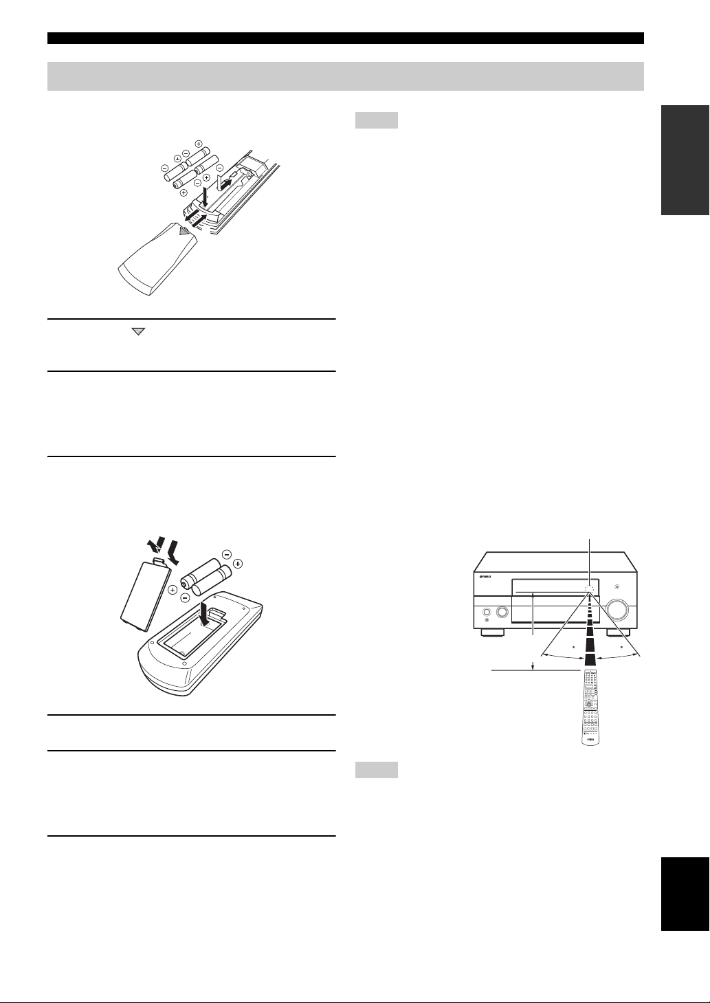
■ Installing batteries in the remote control
1 Press the part and slide the battery
compartment cover off.
2 Insert the four supplied batteries
(AAA, R03, UM-4) according to the polarity
markings (+ and –) on the inside of the
battery compartment.
3 Slide the cover back until it snaps into place.
■ Installing batteries in the Zone 2/Zone 3
remote control (Except Europe model)
1
3
Notes
• Change all of the batteries if you notice the following
conditions:
– the operation range of the remote control decreases.
– the TRANSMIT indicator does not flash or its light becomes
dim.
• Do not use old batteries together with new ones.
• Do not use different types of batteries (such as alkaline and
manganese batteries) together. Read the packaging carefully as
these different types of batteries may have the same shape and
color.
• If the batteries have leaked, dispose of them immediately. Avoid
touching the leaked material or letting it come into contact with
clothing, etc. Clean the battery compartment thoroughly before
installing new batteries.
• Do not throw away batteries with general house waste; dispose
of them correctly in accordance with your local regulations.
• If the remote control is without batteries for more than 2
minutes, or if exhausted batteries remain in the remote control,
the contents of the memory may be cleared. When the memory
is cleared, insert new batteries, set up the remote control code
and program any acquired functions that may have been
cleared.
■ Using the remote control
The remote control transmits a directional infrared ray.
Be sure to aim the remote control directly at the remote
control sensor on this unit during operation.
Remote control sensor
INTRODUCTION
2
1 Take off the battery compartment cover.
2 Insert the two supplied batteries (AAA, R03,
UM-4) according to the polarity markings
(+ and –) on the inside of the battery
compartment.
3 Snap the battery compartment cover back
into place.
Approximately 6 m
Notes
• Do not spill water or other liquids on the remote control.
• Do not drop the remote control.
• Do not leave or store the remote control in the following types
of conditions:
– places of high humidity, such as near a bath
– places of high temperatures, such as near a heater or stove
– places of extremely low temperatures
– dusty places
30 30
9 En
English
Page 12
CONTROLS AND FUNCTIONS
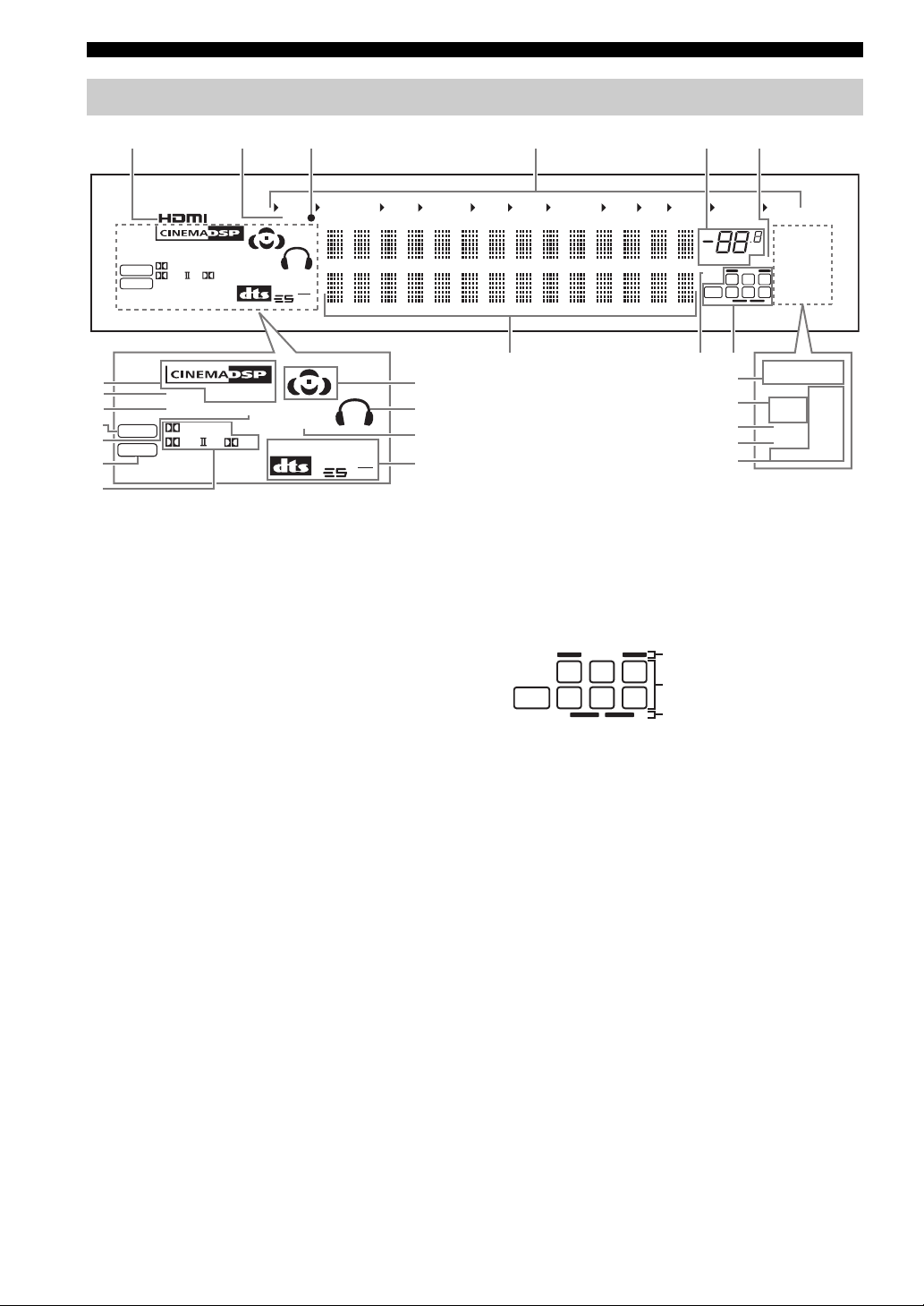
Front panel display
654321
0
A
B
C
D
E
DSD
PCM
DSD
PCM
VIRTUAL
YPAO
DIGITAL
PL x
VIRTUAL
YPAO
HiFi DSP
ENHANCER
EX
HiFi DSP
ENHANCER
DIGITAL
PL x
SILENT
CINEMA
MATRIX
EX
V-A UX
DOCK
DISCRETE
96
24
SILENT
CINEMA
MATRIX
DVR/VCR 2
DISCRETE
96
24
VCR 1
CBL/SAT
G
H
I
J
F
1 HDMI indicator
Lights up when the signal of the selected input source is
input at HDMI IN 1 or HDMI IN 2 jacks (see page 19).
2 DOCK indicator
Lights up when you station your iPod in a YAMAHA iPod
universal dock (such as the YDS-10, sold separately)
connected to the DOCK terminal of this unit
(see page 27).
3 Battery charge indicator
Lights up when this unit charges the battery of the
stationed iPod in the standby mode of this unit (see
page 66).
4 Input source indicators
The corresponding cursor lights up to show the currently
selected input source.
5 VOLUME level indicator
Indicates the current volume level.
6 MUTE indicator
Flashes while the MUTE function is on (see page 41).
7 Multi-information display
Shows the name of the current sound field program and
other information when adjusting or changing settings.
DVD
DTV
MD/TAPE
CD-R
CD
PHONO
VOLUME
96/24
87
MULTI CH
LL C R
LFE
SL SB SR
9
K
L
M
N
O
dB
MUTE
TUNER
TUNED
AUTO
STEREO
TUNED
MEMORY
AUTO
PS
ZONE2
PTY
RT
ZONE3
NIGHT
CT
SLEEP
EON
PTY HOLD
STEREO
MEMORY
PS
ZONE2
PTY
RT
ZONE3
NIGHT
CT
SLEEP
EON
PTY HOLD
O........ U.K. and Europe models only
8 96/24 indicator
Lights up when a DTS 96/24 signal is input to this unit.
9 Input channel and speaker indicators
Presence speaker indicators
LFE
L CR
SL SB SR
Input channel indicators
Surround back speaker indicators
Input channel indicators
Indicate the channel components of the current digital
input signal.
Presence and surround back speaker
indicators
Light up according to the number of presence and
surround back speakers set for “PRESENCE SP” (see
page 82) and “SB L/R SP” (see page 82) in “SOUND
MENU” when “TEST” in “SOUND MENU” is set to
“ON” (see page 85).
y
You can make settings for the presence and surround back
speakers automatically by running “AUTO SETUP” (see
page 32) or manually by adjusting settings for “PRESENCE SP”
(see page 82) and “SB L/R SP” (see page 82) in “SOUND
MENU”.
10 En
Page 13

CONTROLS AND FUNCTIONS
0 DSP indicators
The respective indicator lights up when any of the DSP
sound field programs are selected.
CINEMA DSP indicator
Lights up when you select a CINEMA DSP sound
field program (see page 45).
HiFi DSP indicator
Lights up when you select a HiFi DSP sound field
program (see page 45).
A VIRTUAL indicator
Lights up when Virtual CINEMA DSP is active (see
page 49).
B YPAO indicator
Lights up when you run “AUTO SETUP” and when the
speaker settings set in “AUTO SETUP” are used without
any modifications (see page 32).
C DSD indicator
Lights up when this unit is producing DSD (Direct Stream
Digital) digital audio signals.
D ENHANCER indicator
Lights up when the Compressed Music Enhancer mode is
turned on (see page 52).
E PCM indicator
Lights up when this unit is reproducing PCM (Pulse Code
Modulation) digital audio signals.
F Dolby decoder indicators
The respective indicator lights up when any of the Dolby
decoders of this unit function.
G Sound field indicators
Light up to indicate the active DSP sound fields.
Presence DSP sound field
Listening position
Surround left
DSP sound field
Surround back DSP sound field
Surround right
DSP sound field
H Headphones indicator
Lights up when headphones are connected (see page 41).
I SILENT CINEMA indicator
Lights up when headphones are connected and a sound
field program is selected (see page 49).
J DTS decoder indicators
The respective indicator lights up when any of the DTS
decoders of this unit function.
K Tuner indicators
Lights up when this unit is in the FM or AM tuning mode.
TUNED indicator
Lights up when this unit is tuned into a station
(see page 54).
STEREO indicator
Lights up when this unit is receiving a strong signal
for an FM stereo broadcast while the AUTO indicator
is lit (see page 54).
AUTO indicator
Lights up when this unit is in the automatic tuning
mode (see page 54).
MEMORY indicator
Flashes to show that a station can be stored
(see page 58).
L ZONE2/ZONE3 indicators
Lights up when Zone 2 or Zone 3 is turned on
(see page 107).
M NIGHT indicator
Lights up when you select a night listening mode
(see page 53).
N SLEEP indicator
Lights up while the sleep timer is on (see page 43).
O Radio Data System indicators
(U.K. and Europe models only)
PS, PTY, RT and CT
Light up according to the selected Radio Data System
display mode.
EON
Lights up when the EON data service is being
received.
PTY HOLD
Lights up while searching for the Radio Data System
stations in the PTY SEEK mode.
INTRODUCTION
11 En
English
Page 14
CONTROLS AND FUNCTIONS
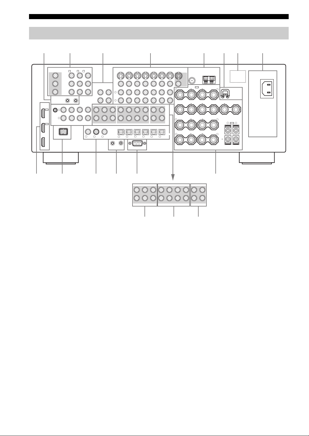
Rear panel
1
8765432
COMPONENT VIDEO
MONITOR OUT
Y
P
B
P
R
REMOTE
HDMI
IN 2
CBL/
SAT
IN 1
DVD
OUT
DVD
DTV
CBL/SAT
A B
C
Y
P
B
P
R
OUT
IN
GND
CD
PHONO
L
R
DOCK
AUDIO
IN
(PLAY)
IN
(PLAY)
MD/
TAPE
FRONT(6CH)
CENTER
CD-R
(REC)
OUT
SUB
WOOFER
MULTI CH INPUT
CD
1
VD
D
SB(8CH)
32
DVR/
VCR2
OUT
(REC)
SURROUND
COAXIAL
1
L
R
DIGITAL INPUT
CONTROL OUT
2
CENTER
WOOFER
4
DVD
SUB
CD
VIDEO
CBL/SAT
IN
DTV
SINGLE(SB)
SURROUND
FRONT
SUR.BACK/
PRESENCE
PRE OUT
DTV
6
DVD
5
7
RS-232C
DVR/VCR 2
OUT
IN
ZONE 3
ZONE OUT
DIGITAL OUTPUT
MD/
98
TAPE
OUT
MONITOR OUT
S VIDEO
VIDEO
+
R
+
+
R
+
OPTICAL
R
CD-R
VCR 1
ZONE 2
CBL/
SAT
FM
SP1
PRESENCE
SURROUND BACK/
BI-AMP
SURROUND
FRONT
GND
ANTENNA
SINGLE
AM
SPEAKERS
AC IN
+
L
WRENCH
HOLDER
CENTER
+
+
L
+
L
+
R
L
SP2
+
AC OUTLETS
DCBA09
SINGLE(SB)
CENTER
WOOFER
SUB
FRONT(6CH)
SB(8CH)
MULTI CH INPUT
SURROUND
CENTER
SUB
WOOFER
FRONT
PRE OUT
SURROUND
SUR.BACK/
PRESENCE
ZONE 2
ZONE 3
ZONE OUT
GFE
1 REMOTE jacks
See page 106 for details.
2 COMPONENT VIDEO jacks
See pages 21 and 22 for connection information.
3 Audio component jacks
See page 24 for connection information.
4 Video component jacks
See pages 21 and 22 for connection information.
5 ANTENNA terminals
See page 28 for connection information.
6 WRENCH HOLDER
Use to hook the supplied speaker terminal wrench when
not in use (see page 15).
7 VOLTAGE SELECTOR
(Asia and General models only)
See page 29 for details.
8 AC IN/OUTLET(S)
See page 29 for connection information.
9 HDMI connectors
See page 19 for connection information.
0 DOCK terminal
See page 27 for connection information.
A DIGITAL INPUT/OUTPUT jacks
See page 22 for connection information.
B CONTROL OUT jack
This is a control expansion terminal for custom
installation.
C RS-232C terminal
This is a control expansion terminal for factory use only.
Consult your dealer for details.
D Speaker terminals
See page 14 for connection information.
E MULTI CH INPUT jacks
See page 26 for connection information.
F PRE OUT jacks
See page 25 for connection information.
G ZONE OUT jacks
See page 106 for connection information.
12 En
Page 15
Placing speakers
CONNECTIONS
CONNECTIONS
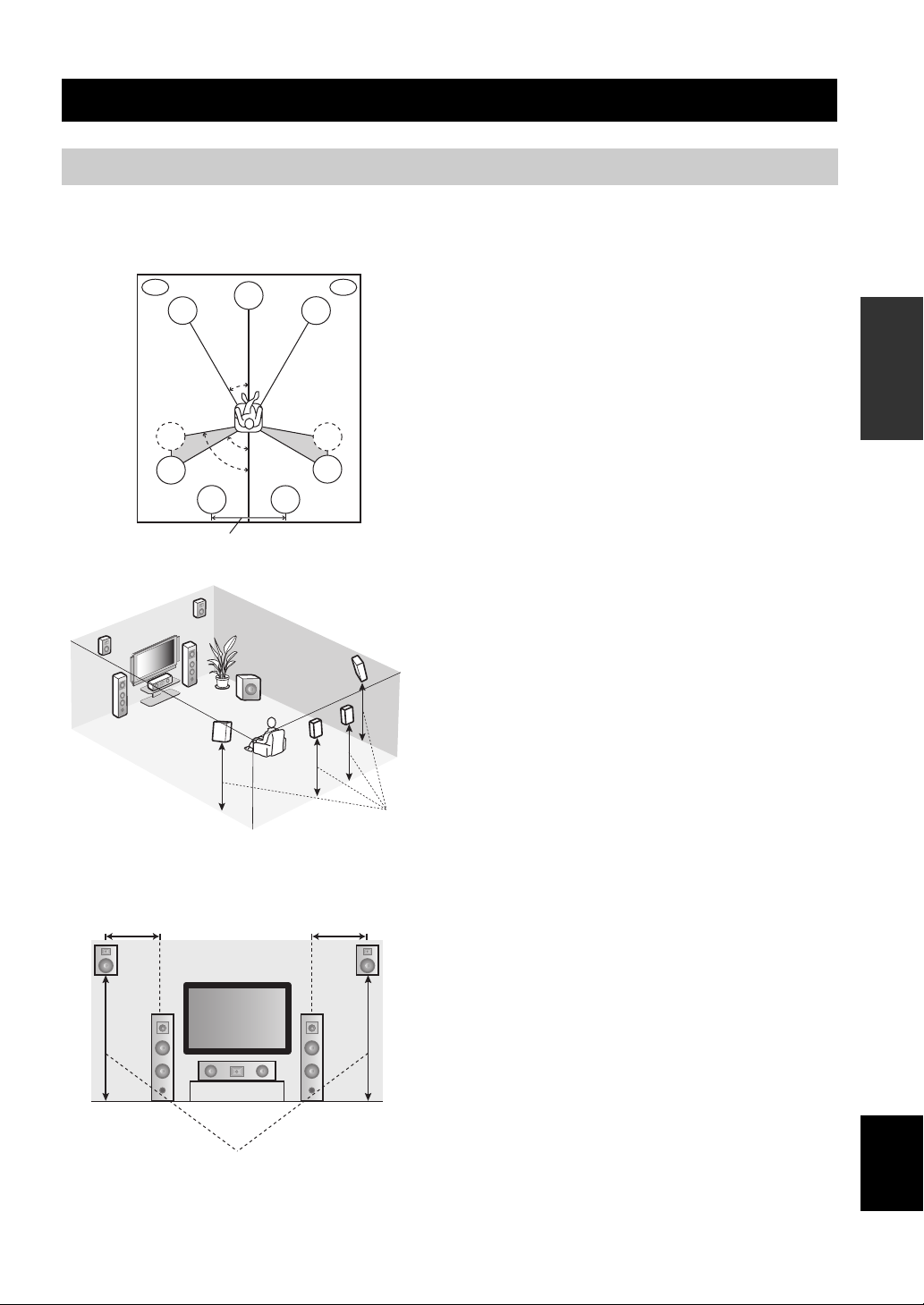
The speaker layout below shows the speaker setting we
recommend. You can use it to enjoy CINEMA DSP and
multi-channel audio sources.
PL
FL
SL
SL
PR
PL
FL
0.5 to 1 m 0.5 to 1 m
FL
FR
C
SL
C
30˚
60˚
80˚
SBL
30 cm or more
SBR
SW
C
1.8 m
SBL
PR
FR
SR
SR
SR
SBR
1.8 m
PRPL
FR
Front left and right speakers (FL and FR)
The front speakers are used for the main source sound plus
effect sounds. Place these speakers at an equal distance from
the ideal listening position. The distance of each speaker
from each side of the video monitor should be the same.
Center speaker (C)
The center speaker is for the center channel sounds
(dialog, vocals, etc.). If for some reason it is not practical
to use a center speaker, you can do without it. Best results,
however, are obtained with the full system. Place the
center speaker centrally between the front speakers and as
close to the monitor as possible, such as directly over or
under it.
Surround left and right speakers (SL and SR)
The surround speakers are used for effect and surround
sounds. Place these speakers behind your listening
position, facing slightly inwards, about 1.8 m above the
floor.
Surround back left and right speakers
(SBL and SBR)
The surround back speakers supplement the surround
speakers and provide more realistic front-to-back
transitions. Place these speakers directly behind the
listening position and at the same height as the surround
speakers. They should be positioned at least 30 cm apart.
Ideally, they should be positioned at the same width as that
of the front speakers.
Presence left and right speakers (PL and PR)
The presence speakers supplement the sound from the front
speakers with extra ambient effects produced by CINEMA
DSP (see page 126). These effects include sounds that
filmmakers intend to locate a little farther back behind the
screen in order to create more theater-like ambience. Place
these speakers at the front of the room about 0.5 to 1 m
outside the front speakers, facing slightly inward, and about
1.8 m above the floor.
Subwoofer (SW)
The use of a subwoofer with a built-in amplifier, such as
the YAMAHA Active Servo Processing Subwoofer
System, is effective not only for reinforcing bass
frequencies from any or all channels, but also for high
fidelity sound reproduction of the LFE (low-frequency
effect) channel included in Dolby Digital and DTS
sources. The position of the subwoofer is not so critical,
because low bass sounds are not highly directional. But it
is better to place the subwoofer near the front speakers.
Turn it slightly toward the center of the room to reduce
wall reflections.
PREPARATION
English
13 En
Page 16
CONNECTIONS
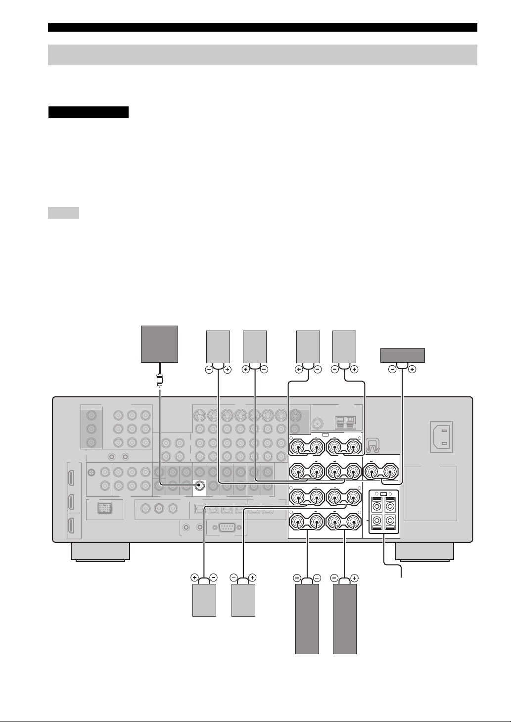
Connecting speakers
Be sure to connect the left channel (L), right channel (R), “+” (red) and “–” (black) properly. If the connections are faulty,
no sound will be heard from the speakers, and if the polarity of the speaker connections is incorrect, the sound will be
unnatural and lack bass.
CAUTION
• Before connecting the speakers, make sure that this unit is turned off (see page 31).
• Do not let the bare speaker wires touch each other or do not let them touch any metal part of this
unit. This could damage this unit and/or speakers.
• Use magnetically shielded speakers. If this type of speaker still creates interference with the
monitor, place the speakers away from the monitor.
• If you are to use 6 ohm speakers, be sure to set “SP IMP.” to “6ΩMIN” before using this unit (see
page 30). 4 ohm speakers can be also used as the front speakers (see page 111).
Notes
• A speaker cord is actually a pair of insulated cables running side by side. Cables are colored or shaped differently, perhaps with a
stripe, groove or ridge. Connect the striped (grooved, etc.) cable to the “+” (red) terminals of this unit and your speaker. Connect the
plain cable to the “–” (black) terminals.
• The low-frequency signals of other speakers set to “SML” (or “SMALL”) or to “NONE” in “SPEAKER SET” (see pages 80 and 82)
are directed to the speakers selected in “LFE/BASS OUT” (see page 80).
• You can connect both surround back and presence speakers to this unit, however they do not output sound simultaneously. You can set
to prioritize either set of speakers using the “PRIORITY” parameter in “MANUAL SETUP” (see page 82).
• You can use the PRESENCE terminals to connect the Zone 2 or Zone 3 speakers as well as the presence speakers (see page 106).
Subwoofer
Surround back speakers
Left
Right
Presence speakers
Right
Left
SUB
WOOFER
PRE OUT
Right
Left
Surround speakers
Center speaker
+
R
SURROUND BACK/
+
BI-AMP
SURROUND
+
R
FRONT
+
R
+
L
CENTER
+
SINGLE
+
L
+
L
+
R
L
SP2
+
SPEAKERS
SP1
PRESENCE
Zone 2 or Zone 3
speakers
(see page 106)
14 En
Right
Left
Front speakers
Page 17
CONNECTIONS
FRONT terminals
Connect front left and right speakers to these terminals.
CENTER terminals
Connect a center speaker to these terminals.
SURROUND terminals
Connect surround left and right speakers to these
terminals.
SURROUND BACK terminals
Connect surround back left and right speakers to these
terminals.
Note
When you use a surround back speaker, connect the speaker to the
left SURROUND BACK terminal (SINGLE).
PRESENCE terminals
Connect presence left and right speakers to these
terminals.
SUBWOOFER jack
Connect a subwoofer with a built-in amplifier (such as the
YAMAHA Active Servo Processing Subwoofer System)
to this jack.
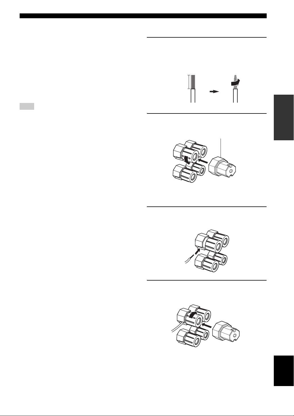
■ Connecting the speaker cable
1 Remove approximately 10 mm of insulation
from the end of each speaker cable and then
twist the exposed wires of the cable together
to prevent short circuits.
10 mm
PREPARATION
2 Loosen the knob using the supplied speaker
terminal wrench.
Speaker terminal wrench
Red: positive (+)
Black: negative (–)
3 Insert one bare wire into the hole on the side
of each terminal.
4 Tighten the knob to secure the wire using the
supplied speaker terminal wrench.
English
15 En
Page 18
CONNECTIONS
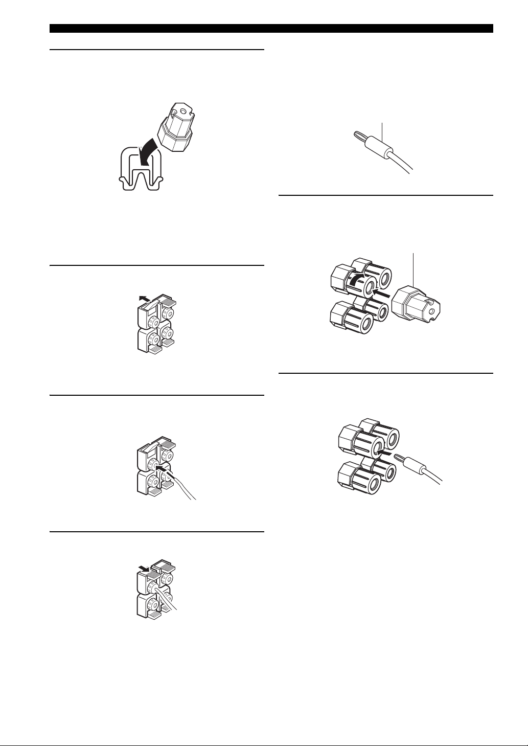
5 Hook the speaker terminal wrench onto the
WRENCH HOLDER on the rear panel of this
unit when not in use.
■ Connecting the banana plug
(except U.K., Europe, Asia and Korea
models)
The banana plug is a single-pole electrical connector
widely used to terminate speaker cables.
Banana plug
■ Connecting to the SP2 speaker
terminals
Connect Zone 2 or Zone 3 speakers to these terminals (see
page 106).
1 Open the tab.
Red: positive (+)
Black: negative (–)
2 Insert one bare wire into the hole on the
terminal.
1 Tighten the knob using the supplied speaker
terminal wrench.
Speaker terminal wrench
Red: positive (+)
Black: negative (–)
2 Insert the banana plug connector into the
end of the corresponding terminal.
3 Close the tab to secure the wire.
16 En
y
You can also use the banana plug with the SP2 speaker terminals.
Open the tab and then insert one banana plug into the hole on the
terminal. Do not close the tab after connecting the banana plug.
Page 19
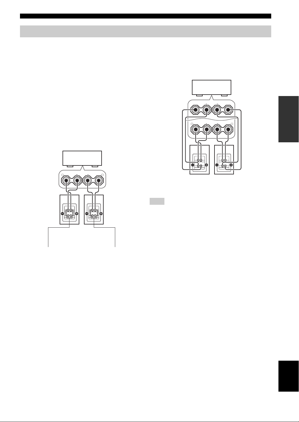
Using bi-amplification connections
CONNECTIONS
Some of the speakers have speaker wire connections that
allow bi-amplification to enhance the performance of the
speaker system. This unit allows you to make biamplification connection to one speaker system. Check if
your speakers support bi-amplification. As these speakers
are shipped to you, you will note shorting bars or bridges,
one connecting the two red input terminals and the other
connecting the two black input terminals. Remove these
shorting bars or bridges only if you plan to bi-amplify
your speakers.
■ Conventional connection
If you want to connect your speakers as traditional
loudspeakers using the conventional connection method,
connect your speakers using the regular left and right
speaker wire connections and ignore the second set of
terminals.
This unit
+ +
R
FRONT
L
■ Bi-amplification connection
To make the bi-amplification connections, use the FRONT
and SURROUND BACK terminals as shown below. To
activate the bi-amplification connections, set “BI-AMP”
to “ON” in “ADVANCED SETUP” (see page 112).
This unit
SURROUND BACK/
+
BI-AMP
+
R
FRONT
Right
Front speakers
Note
Remove the shorting bars or bridges to separate the LPF (low
pass filter) and HPF (high pass filter) crossovers.
SINGLE
Left
+
+
L
PREPARATION
Shorting bars
or bridges
Right Left
Front speakers
Shorting bars
or bridges
English
17 En
Page 20
CONNECTIONS
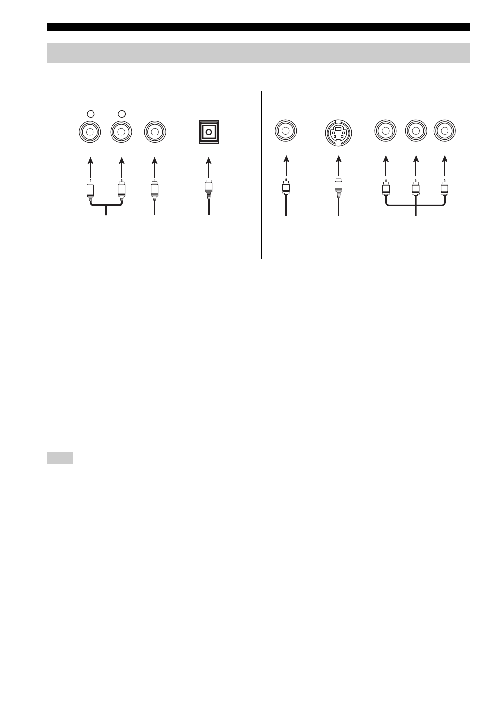
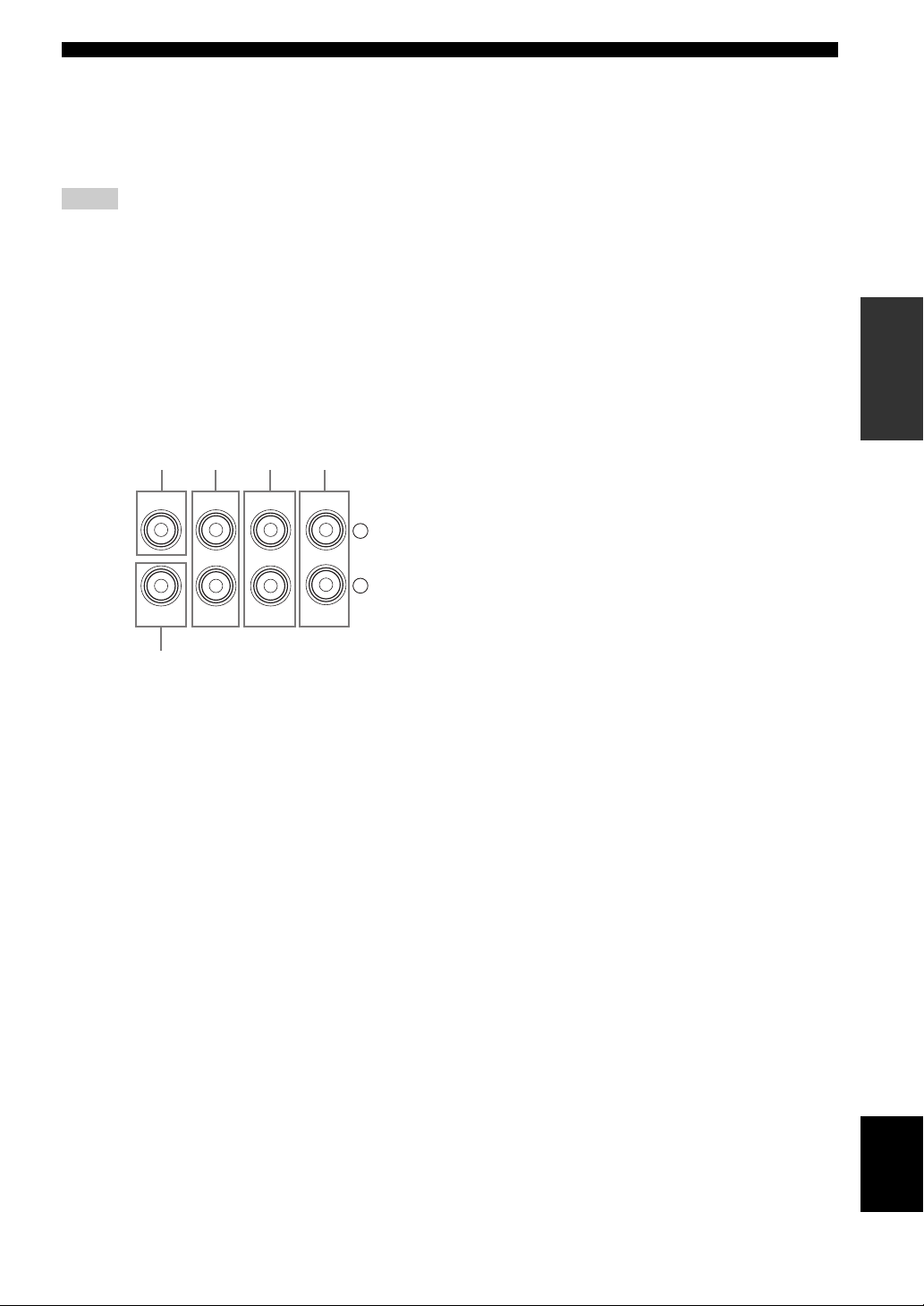
Information on jacks and cable plugs
Audio jacks and cable plugs Video jacks and cable plugs
AUDIO
L
L
Left and right
analog audio
cable plugs
R
(Red)(White) (Orange) (Yellow) (Green) (Blue) (Red)
R
DIGITAL
COAXIAL
C
Coaxial
digital audio
cable plug
DIGITAL
OPTICAL
O
Optical
digital
audio cable
plug
■ Audio jacks
This unit has three types of audio jacks. Connection
depends on the availability of audio jacks on your other
components.
AUDIO jacks
For conventional analog audio signals transmitted via left
and right analog audio cables. Connect red plugs to the
right jacks and white plugs to the left jacks.
DIGITAL COAXIAL jacks
For digital audio signals transmitted via coaxial digital
audio cables.
DIGITAL OPTICAL jacks
For digital audio signals transmitted via optical digital
audio cables.
Note
You can use the digital jacks to input PCM, Dolby Digital and
DTS bitstreams. When you connect components to both the
COAXIAL and OPTICAL jacks, priority is given to the signals
input at the COAXIAL jack. All digital input jacks are
compatible with 96-kHz sampling digital signals.
VIDEO S VIDEO
V
Composite
video cable
plug
cable plug
S
S-video
COMPONENT VIDEO
Y R PB P
PB
Y
Component
video cable
plugs
P
R
■ Video jacks
This unit has three types of video jacks. Connection
depends on the availability of input jacks on your video
monitor.
VIDEO jacks
For conventional composite video signals transmitted via
composite video cables.
S VIDEO jacks
For S-video signals, separated into the luminance (Y) and
chrominance (C) video signals transmitted on separate
wires of S-video cables.
COMPONENT VIDEO jacks
For component video signals, separated into the
luminance (Y) and chrominance (P
transmitted on separate wires of component video cables.
y
This unit equips the video connection function. See pages 20 and
90 for details.
B, PR) video signals
18 En
Page 21
CONNECTIONS
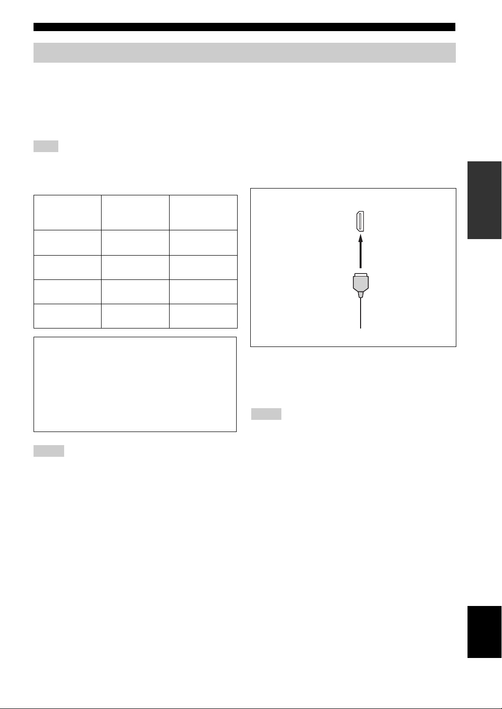
Information on HDMI
This unit has the HDMI IN 1, HDMI IN 2 and HDMI OUT jacks for digital audio and video signal input/output. Connect
the HDMI IN 1 or HDMI IN 2 jack of this unit to the HDMI output jack of other HDMI components (such as a DVD
player). Connect the HDMI OUT jack of this unit to the HDMI IN jack of other HDMI components (such as a TV and a
projector).
The video or audio signals input at the HDMI IN 1 or HDMI IN 2 jack of the selected input source are output at the
HDMI OUT jack of this unit.
Note
You can check the potential problem about the HDMI connection (see page 42).
■ HDMI compatibility with this unit
■ HDMI jack and cable plug
PREPARATION
Audio signal
types
2ch Linear
PCM
Multi-ch
Linear PCM
DSD 2/5.1ch,
Bitstream Dolby Digital,
Audio signal
formats
2ch, 32-192 kHz,
16/20/24 bit
8ch, 32-192 kHz,
16/20/24 bit
2.8224 MHz, 1 bit
DTS
Compatible
HDMI
components
CD, DVD-Video,
DVD-Audio, etc.
DVD-Audio, etc.
SACD, etc.
DVD-Video, etc.
This unit’s HDMI interface is based on the following
standards:
• HDMI Version 1.2a (High-Definition Multimedia
Interface Specification Version 1.2a) licensed by
HDMI Licensing, LLC.
• HDCP Revision 1.1 (High-bandwidth Digital
Content Protection System Revision 1.1) licensed
by Digital Content Protection, LLC.
Notes
• When CPPM copy-protected DVD audio is played back, video
and audio signals may not be output depending on the type of
the DVD player.
• This unit is not compatible with HDCP-incompatible HDMI or
DVI components.
HDMI
HDMI cable plug
y
• We recommend using an HDMI cable shorter than 5 meters
with the HDMI logo printed on it.
• Use a conversion cable (HDMI jack
this unit to other DVI components.
↔ DVI-D jack) to connect
Notes
• Do not disconnect or connect the cable or turn off the power of
the HDMI components connected to the HDMI OUT jack of
this unit while data is being transferred. Doing so may disrupt
playback or cause noise.
• Audio signals input at input jacks other than the HDMI IN 1 or
HDMI IN 2 of this unit cannot be digitally output at the
HDMI OUT jack.
• If you turn off the power of the video monitor connected to the
HDMI OUT jack via a DVI connection, this unit may fail to
establish the connection to the component.
• The analog video signals input at the composite video, S-video
and component video jacks can be digitally up-converted to be
output at the HDMI OUT jack. Set “V CONV.” to “ON” in
“MANUAL SETUP” (see page 91) to activate this feature.
19 En
English
Page 22
CONNECTIONS
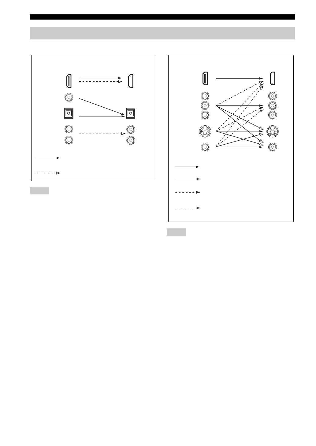
Audio and video signal flow
■ Audio signal flow
OutputInput
HDMI
DIGITAL AUDIO
(COAXIAL)
DIGITAL AUDIO
(OPTICAL)
AUDI O
Digital output
Analog output
Notes
• 2-channel as well as multi-channel PCM, Dolby Digital and
DTS signals input at the HDMI IN 1 or HDMI IN 2 jack can be
output at the HDMI OUT jack only when “SUPPORT AUDIO”
is set to “OTHER” (see page 86).
• Audio signals input at the HDMI IN jacks are not output at the
analog AUDIO OUT and DIGITAL OUTPUT jacks.
■ Video signal flow
Input
HDMI
COMPONENT
VIDEO
S VIDEO
VIDEO
Through
Video conversion (see page 90)
Component interlace/progressive
up-conversion (see page 91)
HDMI interlace/progressive
up-conversion (see page 91)
Notes
• When the analog video signals are input at the COMPONENT
VIDEO, S VIDEO and VIDEO jacks, the priority order of the
input signals is as follows:
1. COMPONENT VIDEO
2. S VIDEO
3. VIDEO
• The analog video signals output at the COMPONENT VIDEO
jacks can be deinterlaced from 480i (NTSC)/576i (PAL) to
480p/576p. Set “CMPNT I/P” to “ON” in MANUAL SETUP to
activate this feature (see page 91).
• Digital video signals input at the HDMI IN 1 or HDMI IN 2
jack cannot be output from analog video output jacks.
• The analog component video signals with
480i (NTSC)/576i (PAL) of resolution are converted to the
s-video or composite video signals and output at the S VIDEO
MONITOR OUT and VIDEO MONITOR OUT jacks.
• Component interlace/progressive conversion (see page 91) and
HDMI interlace/progressive up-conversion (see page 91) are
available only when “V CONV.” is set to “ON” (see page 90).
• Use the “HDMI I/P” parameter in “OPTION MENU” to
deinterlace the analog video signals output at the HDMI OUT
jack (see page 91). When the analog video signals with 1080i or
720p of resolution are up-converted to HDMI and output at the
HDMI OUT jack, the picture quality may worsen.
• The OSD signal is not output at the VCR 1 OUT and
DVR/VCR 2 OUT jacks and is not recorded.
• The color of the letters and images in the OSD may differ
depending on the input signals and your video monitor.
Output
20 En
Page 23
CONNECTIONS
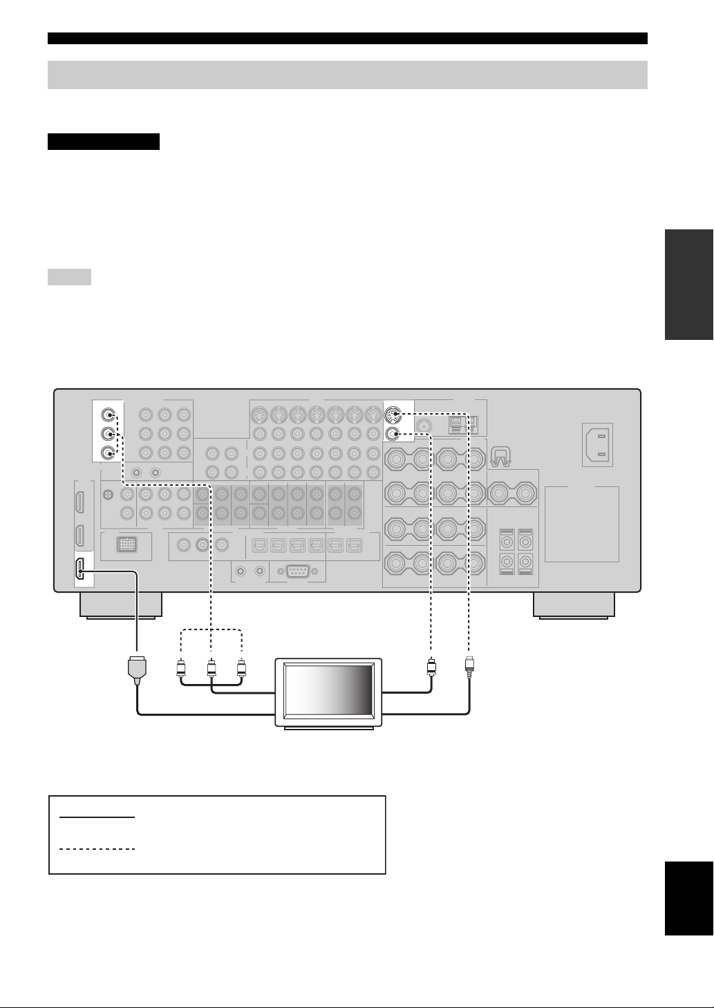
Connecting a TV monitor or projector
Connect your TV (or projector) to the HDMI OUT jack, the COMPONENT VIDEO MONITOR OUT jacks, the S
VIDEO MONITOR OUT jack or the VIDEO MONITOR OUT jack of this unit.
CAUTION
Do not connect this unit or other components to the AC power supply until all connections between
components are complete.
y
You can select to play back HDMI audio signals on this unit or on another HDMI component connected to the HDMI OUT jack on the
rear panel of this unit. Use the “SUPPORT AUDIO” parameter in “SOUND MENU” to select the component to play back HDMI audio
signals (see page 86).
Notes
• Some video monitors connected to this unit via a DVI connection fail to recognize the HDMI audio/video signals being input if they
are in the standby mode. In this case, the HDMI indicator flashes irregularly.
• Set “V CONV.” in “OPTION MENU” to “ON” (see page 90) to display the short message display and parameter displays.
• Set “GRAY BACK” in “OPTION MENU” to “ON” (see page 90) to display the parameter displays.
• The SET MENU and parameter displays appear with the gray background depending on the input video signal format and the setting
of the parameters in “DISPLAY SET” (see page 90).
PREPARATION
COMPONENT VIDEO
MONITOR OUT
Y
P
B
P
R
HDMI
OUT
Y
PRPB
Component video in
HDMI in
VIDEO
MONITOR OUT
S VIDEO
VIDEO
Video in
S-video in
S
V
TV
(or projector)
indicates recommended connections
indicates alternative connections
English
21 En
Page 24
CONNECTIONS
Connecting other components
CAUTION
Do not connect this unit or other components to the AC power supply until all connections between
components are complete.
Notes
• When “V CONV.” is set to “OFF” (see page 90), be sure to make the same type of video connections as those made for your TV (see
page 21). For example, if you connected your TV to the VIDEO MONITOR OUT jack of this unit, connect your other components to
the VIDEO jacks.
• When “V CONV.” is set to “ON” (see page 90), the converted video signals are output only at the MONITOR OUT jacks. When
recording a source, you must make the same type of video connections between each component.
• To make a digital connection to a component other than the default component assigned to each DIGITAL INPUT or DIGITAL
OUTPUT jack, select the corresponding setting for “OPTICAL OUT”, “OPTICAL IN”, or “COAXIAL IN” in “I/O ASSIGNMENT”
(see page 87).
• If you connect your DVD player to both the DIGITAL INPUT (OPTICAL) and the DIGITAL INPUT (COAXIAL) jacks, priority is
given to the signals input at the DIGITAL INPUT (COAXIAL) jack.
• The parameter displays do not appear when the component video signals with 720p, 1080i or 1080p are input.
• The parameter and short message displays do not appear when the component video signals with 480p/576p, 720p, 1080i or 1080p
resolutions are input and output at the VIDEO or S VIDEO MONITOR OUT jacks.
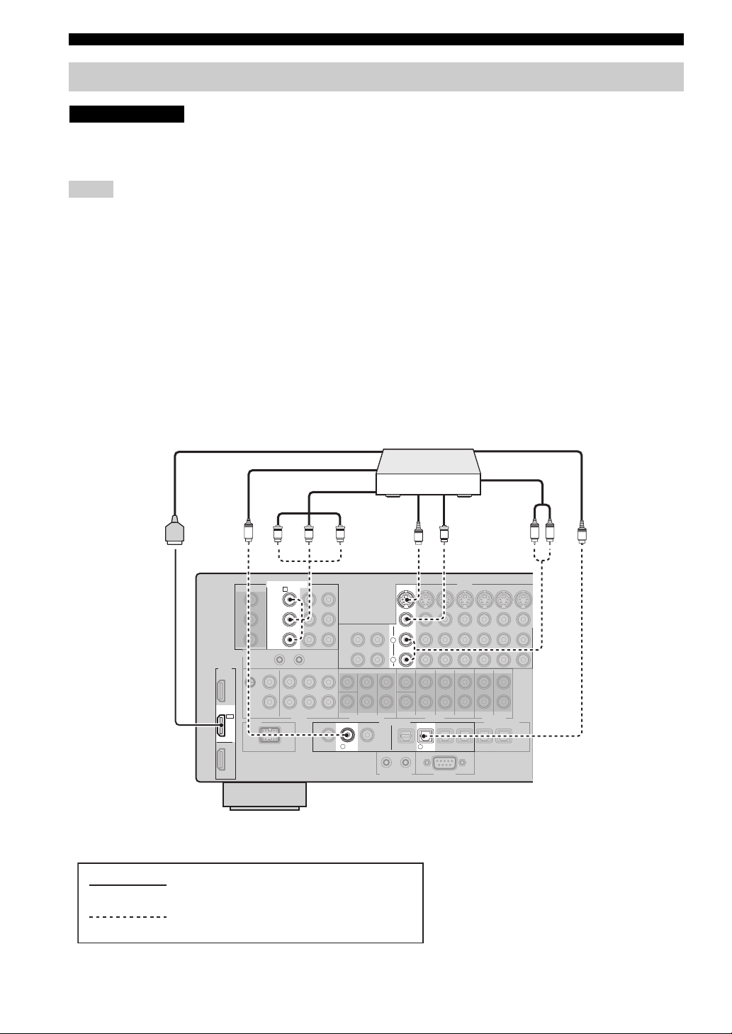
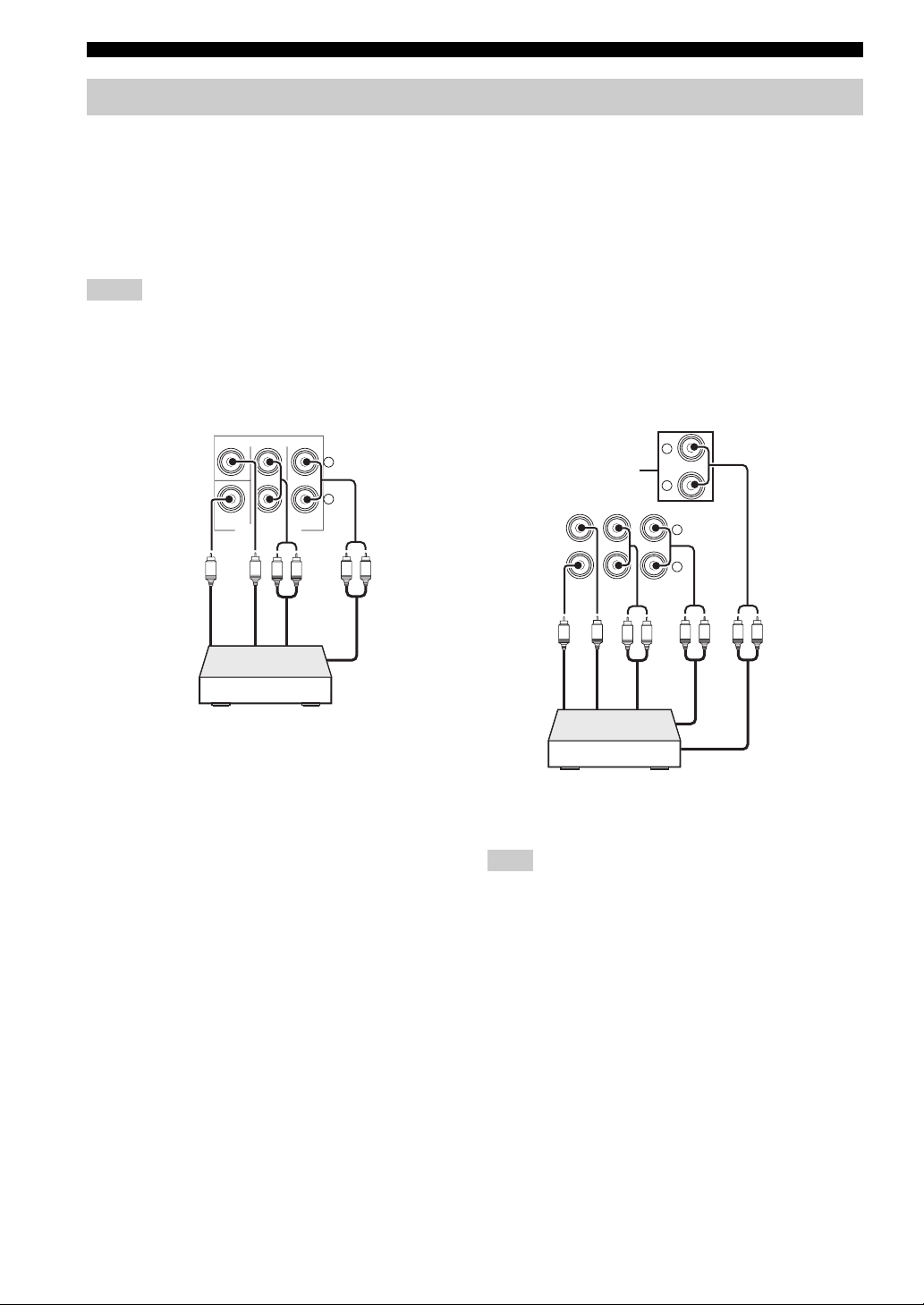
■ Connecting a DVD player
HDMI out
DVD p layer
Coaxial out
Component out
S-video out Video out
Optical out
Audio out
C
PR PB Y
COMPONENT VIDEO
DVD
A
Y
P
B
P
R
HDMI
IN 1
DVD
VD
D
2
indicates recommended connections
indicates alternative connections
DIGITAL INPUT
COAXIAL
OPTICAL
LR
O
V
S
DVD
L
R
VIDEO
DVD
5
22 En
Page 25
CONNECTIONS
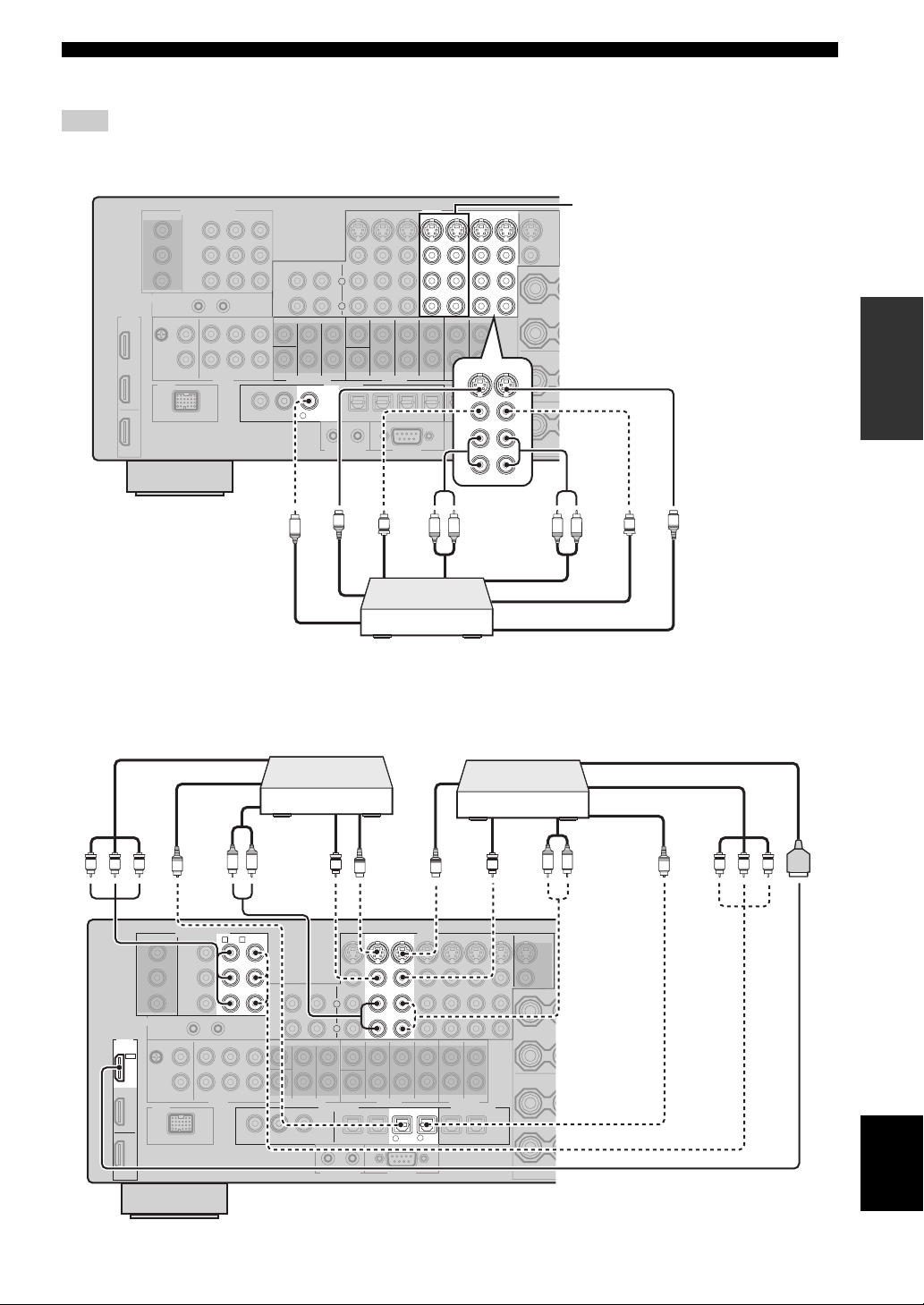
■ Connecting a DVD recorder, PVR or VCR
Note
*1
When you connect another VCR to this unit, connect it to the VCR 1 terminals (S VIDEO IN, VIDEO IN, AUDIO IN, S VIDEO
OUT, VIDEO OUT and AUDIO OUT jacks) same as DVR/VCR 2 terminals except the DIGITAL INPUT (COAXIAL) jack.
C
■ Connecting set-top boxes
L
R
DIGITAL INPUT
COAXIAL
DVR/
3
VCR2
Coaxial out
S-video out
S
Video out
V
DVD recorder, PVR or VCR
VIDEO
DVR/VCR 2
VCR 1
OUT
ININ
OUT
*1
S VIDEO
VIDEO
PREPARATION
R
DVR/VCR 2
IN
O
U
T
R
Audio out
R
L
Audio in
R
V
L
S-video in
Video in
S
Component out
PR PB Y
HDTV decoder
cable TV receiver
HDMI out
Component out
Satellite receiver,
S-video out
Optical out
HDMI
IN 2
CBL/
SAT
Audio out
NENT VIDEO
LR
DTV
CBL/SAT
B
C
O
CO
MP
O
Y
P
B
P
R
Video out
S
DTV
L
R
DIGITAL INPUT
CBL/SAT
6
S-video out
S
VIDEO
CBL/
DTV
7
SAT
VV
OPTICAL
Video out
L R
S VIDEO
VIDEO
Optical out
Audio out
PR PB Y
O
English
23 En
Page 26
CONNECTIONS
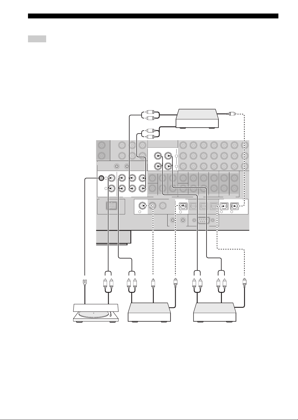
■ Connecting audio components
Notes
• To make a digital connection to a component other than the default component assigned to either the DIGITAL INPUT jack or the
DIGITAL OUTPUT jack, select the corresponding setting for “OPTICAL OUT”, “OPTICAL IN”, or “COAXIAL IN” in “I/O
ASSIGNMENT” (see page 87).
• Connect your turntable to the GND terminal of this unit to reduce noise in the signal. However, you may hear less noise without the
connection to the GND terminal for some turntables.
• The PHONO jacks are only compatible with a turntable with an MM or a high-output MC cartridge. To connect a turntable with a lowoutput MC cartridge to the PHONO jacks, use an in-line boosting transformer or an MC-head amplifier.
• When you connect both the DIGITAL INPUT (OPTICAL) jack and the DIGITAL INPUT (COAXIAL) jack to an audio component,
the priority is given to the DIGITAL INPUT (COAXIAL) jack.
L
R
Optical inAudio out
O
Audio in
L
R
IN
(PLAY)
MD/
TAPE
CD
PHONO
GND
L
R
AUDIO
IN(PLAY)
CD-R
OUT(REC)
CD
1
OUT
(REC)
DIGITAL INPUT
COAXIAL
CD recorder
L
R
CD
4
DIGITAL OUTPUT
MD/
CD-R
98
TAPE
OPTICAL
24 En
Ground
Audio out
Turntable
Audio
out
CD player
C
Coaxial
out
O
Optical
out
LR LRLRLR
Audio
out
Audio
in
MD recorder or
tape deck
O
Optical in
Page 27
■ Connecting an external amplifier
This unit has more than enough power for any home use.
However, if you want to add more power to the speaker
output or if you want to use another amplifier, connect an
external amplifier to the PRE OUT jacks.
Notes
• When you make connections to the PRE OUT jacks, do not
make connections to the SPEAKERS terminals.
• The signals output at the FRONT PRE OUT and CENTER PRE
OUT jacks are affected by the TONE CONTROL settings (see
page 50).
• Each PRE OUT jack outputs the same channel signals as the
corresponding SPEAKERS terminals.
• Adjust the volume level of the subwoofer with the control on
the subwoofer (see page 51).
• Some signals may not be output at the SUBWOOFER PRE
OUT jack depending on the settings for “SPEAKER SET” (see
page 80) and “LFE/BASS OUT” (see page 80).
4321
CONNECTIONS
PREPARATION
CENTER
SUB
WOOFER
FRONT
SURROUND
PRE OUT
SINGLE(SB)
SUR.BACK/
PRESENCE
L
R
5
1 CENTER PRE OUT jack
Center channel output jack.
2 FRONT PRE OUT jacks
Front channel output jacks.
3 SURROUND PRE OUT jacks
Surround channel output jacks.
4 SURROUND BACK/PRESENCE PRE OUT
jacks
Surround back or presence channel output jacks. When
you only connect one external amplifier for the surround
back channel, connect it to the SINGLE (SB) jack.
y
• Set the “SB L/R SP” to “LRGx2”, “LRGx1”, “SMLx2” or
“SMLx1” and “PRESENCE SP” to “NONE” (see page 82) to
output the surround back channel signals at SURROUND
BACK/PRESENCE PRE OUT jacks.
• Set the “PRESENCE SP” to “YES” and “SB L/R SP” to
“NONE” (see page 82) to output the presence channel signals at
SURROUND BACK/PRESENCE PRE OUT jacks.
5 SUBWOOFER PRE OUT jack
Connect a subwoofer with a built-in amplifier.
English
25 En
Page 28
CONNECTIONS
MULTI CH INPUT
SUB
WOOFER
SUB
CENTER
FRONT(6CH)
SURROUND
SB(8CH)
TAPE
MD/
(C)
()
R
L
R
L
Connecting a multi-format player or an external decoder
This unit is equipped with 6 additional input jacks (left and right FRONT, CENTER, left and right SURROUND and
SUBWOOFER) for discrete multi-channel input from a multi-format player, external decoder, sound processor or
pre-amplifier.
If you set “INPUT CH” to “8ch” in “MULTI CH SET” (see page 89), you can use the input jacks assigned as “FRONT”
in “MULTI CH SET” (see page 89) together with the MULTI CH INPUT jacks to input 8-channel signals.
Connect the output jacks on your multi-format player or external decoder to the MULTI CH INPUT jacks. Be sure to
match the left and right outputs to the left and right input jacks for the front and surround channels.
Notes
• When you select the component connected to the MULTI CH INPUT jacks as the input source (see page 41), this unit automatically
turns off the digital sound field processor, and you cannot select sound field programs.
• This unit does not redirect signals input at the MULTI CH INPUT jacks to accommodate for missing speakers. We recommend that
you connect at least a 5.1-channel speaker system before using this feature.
For 6-channel input For 8-channel input
CENTER
FRONT(6CH)
SURROUND
SUB
WOOFER
MULTI CH INPUT
L
R
SB(8CH)
*1
Subwoofer
Center out
out
Multi-format player/
External decoder
LR
LR
Front out
out
Surround
Subwoofer
Center out
LR
Surround back out
Surround out
LRLR
Front out
out
Multi-format player/
External decoder
Note
*1
The analog audio input jacks assigned as “FRONT” in
“MULTI CH SET” (see page 89).
26 En
Page 29
CONNECTIONS
Connecting a YAMAHA iPod universal dock
This unit is equipped with the DOCK terminal on the rear
panel that allows you to connect a YAMAHA iPod
universal dock (such as the YDS-10, sold separately)
where you can station your iPod and control playback of
your iPod using the supplied remote control. Connect a
YAMAHA iPod universal dock (such as the YDS-10, sold
separately) to the DOCK terminal on the rear panel of this
unit using its dedicated cable.
CAUTION
Do not connect this unit to the AC power supply
until all connections between components are
complete.
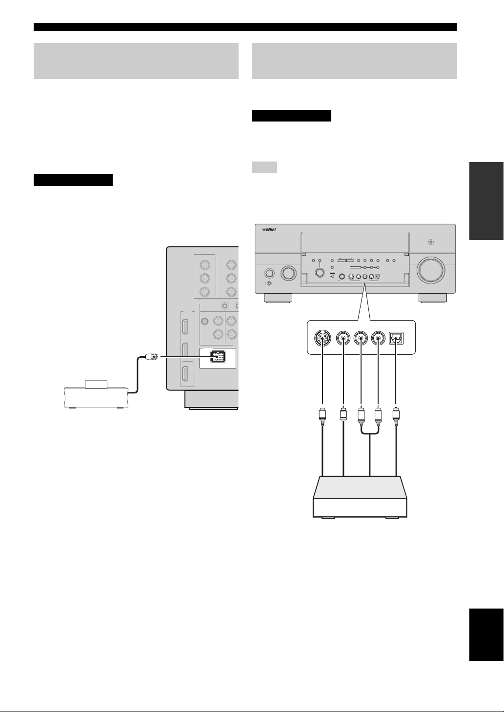
Using the VIDEO AUX jacks on the front panel
Use the VIDEO AUX jacks on the front panel to connect a
game console or a video camera to this unit.
CAUTION
Be sure to turn off the volume of this unit and
other components before making connections.
Note
The audio signals input at the DOCK terminal on the rear panel
take priority over the ones input at the VIDEO AUX jacks.
PURE DIRECT
AUDIO
TONE
CONTROL
SELECT
PROGRAM
S VIDEO
A/B/C/D/E
STRAIGHT
EFFECT
SILENT CINEMA
YPAO
OPTIMIZER
MIC
VIDEO
INPUT
MAIN ZONE
ON/OFF
ON
OFF
MASTER
MEMORY
PRESET/
TUNING
PRESET/TUNING
FM/AM
UNING
T
EDIT
MULTI ZONE
ZONE 2
S VIDEO
VIDEO
VIDEO AUX
PHONES
L
NIGHT
MODE
ENHANCER
MAN'L/AUTO FM
ZONE ON/OFF
ZONE CONTROLS
ZONE 3
L
R
AUDIO
OPTICAL
OPTICAL
R
AUDIO
VOLUME
PREPARATION
YAMAHA iPod universal dock
(such as the YDS-10,
sold separately)
DOCK
S-Video
output
V
S
L
Video
output
Game console or
video camera
R
Audio
output
O
Optical
output
English
27 En
Page 30
CONNECTIONS
Connecting the FM and AM antennas
Both FM and AM indoor antennas are supplied with this
unit. Connect each antenna correctly to the designated
terminals. In general, these antennas should provide
sufficient signal strength.
Notes
• Be sure to set the tuner frequency step (Asia and General
models only) according to the frequency spacing in your area
(see page 111).
• The AM loop antenna should be placed away from this unit.
• The AM loop antenna should always be connected, even if an
outdoor AM antenna is connected to this unit.
• A properly installed outdoor antenna provides clearer reception
than an indoor one. If you experience poor reception quality,
install an outdoor antenna. Consult the nearest authorized
YAMAHA dealer or service center about outdoor antennas.
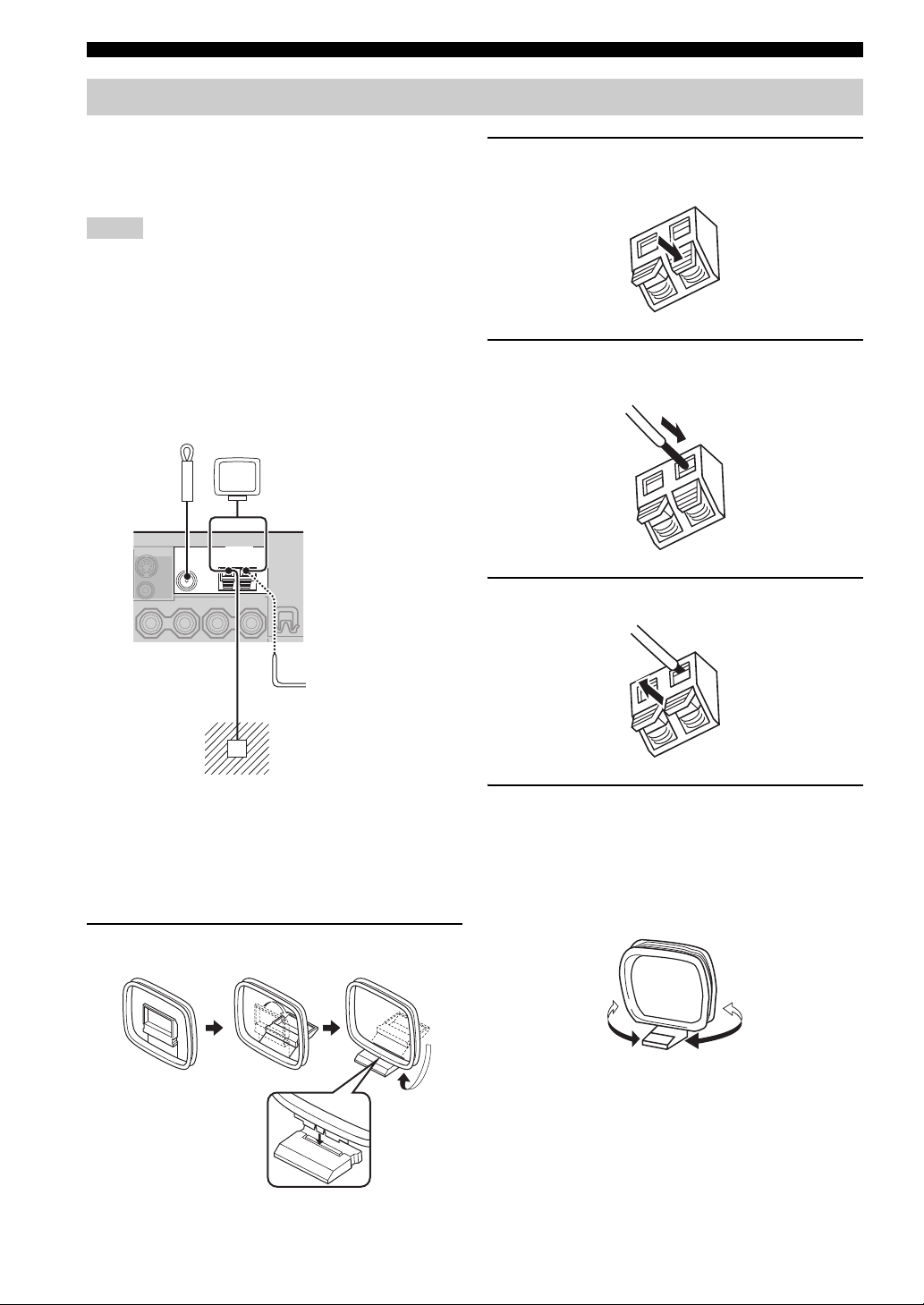
2 Press and hold the tab of the AM ANT
terminal.
3 Insert one of the AM loop antenna lead wires
into the AM ANT terminal.
Indoor FM
antenna
(supplied)
ANTENNA
GND
FM
Ground (GND terminal)
For maximum safety and minimum interference, connect the
antenna GND terminal to a good earth ground. A good earth
ground is a metal stake driven into moist earth.
AM
AM loop
antenna
(supplied)
Outdoor AM antenna
Use a 5 to 10 m vinylcovered wire extended
outdoors from a window.
■ Connecting the AM loop antenna
1 Set up the AM loop antenna.
4 Release the tab of the AM ANT terminal.
5 Repeat steps 2 through 4 to connect the
other lead wire to the GND terminal.
y
Once you have properly connected the AM loop antenna to
this unit, orient the AM loop antenna for the best reception
when you tune into AM stations (see page 54).
28 En
Page 31

CONNECTIONS
Connecting the power cable
■ Connecting the AC power cable
CAUTION
Use the supplied AC cable. Do not use other AC power cables as doing so may result in fire or
electrical shock.
Plug the supplied AC power cable into the AC inlet after all other connections are complete, then plug the AC power
cable into an AC wall outlet.
AC IN
To the AC wall outlet
AC OUTLETS
PREPARATION
■ VOLTAGE SELECTOR
(Asia and General models only)
CAUTION
The VOLTAGE SELECTOR on the rear panel of
this unit must be set for your local voltage
BEFORE plugging the power cable into the AC
wall outlet. Improper setting of the VOLTAGE
SELECTOR may cause damage to this unit and
create a potential fire hazard.
Rotate the VOLTAGE SELECTOR clockwise or
counterclockwise to the correct position using a
straight slot screwdriver.
Voltages are as follows:
Asia model ......................... 220/230–240 V AC, 50/60 Hz
General model ......110/120/220/230–240 V AC, 50/60 Hz
VOLTAGE
SELECTOR
230240V
Voltage indication
■ AC OUTLET(S) (SWITCHED)
U.K. and Australia models ..................................... 1 outlet
Korea model ............................................................... None
Other models ......................................................... 2 outlets
Use these outlet(s) to supply power to any connected
components. Connect the power cable of your other
components to these outlet(s). Power to these outlet(s) is
supplied when this unit is turned on. However, power to
these outlet(s) is cut off when this unit is turned off. For
information on the maximum power or the total power
consumption of the components that can be connected to
these outlet(s), see “SPECIFICATIONS” on page 128.
Memory back-up
The memory back-up circuit prevents the stored data
from being lost even if this unit is in the standby mode.
However, the stored data will be lost in case the power
cable is disconnected from the AC wall outlet or if the
power supply is cut off for more than one week.
English
29 En
Page 32

CONNECTIONS
Setting the speaker impedance
CAUTION
If you are to use 6 ohm speakers, set “SPEAKER
IMP.” to “6ΩMIN” as follows BEFORE using this
unit. 4 ohm speakers can be also used as the
front speakers.
PURE DIRECT
AUDIO
TONE
CONTROL
SELECT
INPUT
MAIN ZONE
ON/OFF
ON
OFF
MASTER
A/B/C/D/E
STRAIGHT
EFFECT
SILENT CINEMA
YPAO
PROGRAM
OPTIMIZER
MIC
MEMORY
PRESET/
TUNING
PRESET/TUNING
FM/AM
TUNING
EDIT
MULTI ZONE
ZONE 2
S VIDEO
VIDEO
VIDEO AUX
PHONES
NIGHT
MODE
ENHANCER
MAN'L/AUTO FM
ZONE ON/OFF
ZONE CONTROLS
ZONE 3
L
R
AUDIO
OPTICAL
VOLUME
2,432,5
1 Make sure this unit is turned off.
See page 31 for details about turning on or off this
unit.
2 Press and hold STRAIGHT on the front panel
and then press MASTER ON/OFF inward to
the ON position to turn on this unit.
This unit turns on, and the advanced setup menu
appears in the front panel display.
4 Press STRAIGHT on the front panel
repeatedly to select “6ΩMIN”.
The following display appears in the front panel
display.
STRAIGHT
EFFECT
IMP.SPEAKER
6
MIN
5 Press MASTER ON/OFF on the front panel to
release it outward to the OFF position to save
the new setting and turn off this unit.
MASTER
Note
The setting you made is reflected next time you turn on this
unit.
While holding
STRAIGHT
EFFECT
down
MASTER
3 Rotate the PROGRAM selector on the front
panel to select “SPEAKER IMP.”.
The following display appears in the front panel
display.
PROGRAM
IMP.SPEAKER
8
MIN
30 En
Page 33

Turning on and off the power
When all connections are complete, turn on this unit.
MAIN ZONE ON/OFF
CONNECTIONS
AUDIO
TONE
CONTROL
SELECT
INPUT
MAIN ZONE
ON/OFF
ON
OFF
MASTER
A/B/C/D/E
STRAIGHT
EFFECT
SILENT CINEMA
YPAO
PROGRAM
OPTIMIZER
MIC
MEMORY
PRESET/
TUNING
PRESET/TUNING
FM/AM
TUNING
EDIT
MULTI ZONE
ZONE 2
S VIDEO
VIDEO
VIDEO AUX
PHONES
NIGHT
MODE
ENHANCER
MAN'L/AUTO FM
ZONE ON/OFF
ZONE CONTROLS
ZONE 3
L
R
AUDIO
OPTICAL
MASTER ON/OFF
■ Turning on this unit
Press MASTER ON/OFF on the front panel
inward to the ON position to turn on this
unit.
When you turns on this unit by pressing MASTER ON/
OFF, the main zone is turned on.
MASTER
Front panel
■ Turning off this unit
Press MASTER ON/OFF on the front panel
again to release it outward to the OFF
position to turn off this unit.
MASTER
Front panel
POWER
POWER
STANDBY
AV
PURE DIRECT
VOLUME
TV
AUDIO SEL
PHONO
TUNER CD
POWER
SLEEP
MULTI CH IN
STANDBY
POWER
■ Turning on the main zone from the
standby mode
Press MAIN ZONE ON/OFF on the front
panel (or POWER on the remote control) to
turn on the main zone.
MAIN ZONE
ON/OFF
Front panel
or
POWER
Remote control
■ Set the main zone to the standby mode
Press MAIN ZONE ON/OFF on the front
panel (or STANDBY on the remote control)
to set the main zone to the standby mode.
MAIN ZONE
STANDBY
ON/OFF
or
PREPARATION
Notes
• MAIN ZONE ON/OFF on the front panel as well as POWER
and STANDBY on the remote control are operational only
when MASTER ON/OFF is pressed inward to the ON position.
• As usual, we recommend using the standby mode to turn off this
unit.
Front panel Remote control
English
31 En
Page 34

AUTO SETUP
AUTO SETUP
This unit employs the YPAO (YAMAHA Parametric Room Acoustic Optimizer) technology which lets you avoid
troublesome listening-based speaker setup and achieves highly accurate sound adjustments automatically. The supplied
optimizer microphone collects and this unit analyzes the sound your speakers produce in your actual listening
environment.
Using AUTO SETUP
Once you have connected the supplied optimizer
microphone to the OPTIMIZER MIC jack on the front
panel and have placed it in a suitable location in your
listening room, run “AUTO SETUP” in the OSD or in the
front panel display.
Notes
• Be advised that it is normal for loud test tones to be output
during the “AUTO SETUP” procedure.
• To achieve the best results, make sure the room is as quiet as
possible while the “AUTO SETUP” procedure is in progress. If
there is too much ambient noise, the results may not be
satisfactory.
y
• You can run “AUTO SETUP” using the system menu that
appears in the OSD or in the front panel display. This manual
uses the OSD illustrations to explain the “AUTO SETUP”
procedure.
• If an error occurs during the “AUTO SETUP” procedure and an
error or warning message appears in the OSD or in the front
panel display, see the “AUTO SETUP” section in
“TROUBLESHOOTING” on pages 120 and 121 for a complete
list of error and warning messages and proper remedies.
• The initial setting for each parameter is indicated in bold.
• If the volume level and the crossover frequency of your
subwoofer can be adjusted, set the volume level to about half
way (or slightly less) and set the crossover frequency to the
maximum.
1 Connect the supplied optimizer microphone
to the OPTIMIZER MIC jack on the front
panel.
AUDIO
TONE
CONTROL
SELECT
PROGRAM
A/B/C/D/E
STRAIGHT
EFFECT
YPAO
OPTIMIZER
PRESET/TUNING
MULTI ZONE
S VIDEO
SILENT CINEMA
PHONES
MIC
PRESET/
TUNING
EDIT
VIDEO
FM/AM
ZONE 2
VIDEO AUX
ZONE ON/OFF
L
AUDIO
MEMORY
MAN'L/AUTO FM
ZONE 3
R
TUNING
MODE
ZONE CONTROLS
OPTICAL
NIGHT
ENHANCER
Omni-directional
microphone
2 Place the optimizer microphone at your
normal listening position on a flat level
surface with the omni-directional
microphone heading upward.
Optimizer microphone
32 En
AMP
SOURCE
PURE DIRECT
AUDIO
STRAIGHT
EFFECT
4
TV
4,14
3-13
y
It is recommended that you use a tripod (etc.) to affix the
optimizer microphone at the same height as your ears would be
when you are seated in your listening position. You can use a 6
+
+
+
VOLUME
TV VOL
CH
––
–
TV MUTE
TV INPUT
MUTE
PRESET/CH
SET MENU
LEVEL
MENU
TITLE
SRCH MODE
BAND
ENTER
A/B/C/D/E
PARAMETER
DISPLAY
RETURN
mm diameter screw to fix the optimizer microphone to a tripod
(etc.).
Page 35

AUTO SETUP
3 Make sure of the following check points
before starting the AUTO SETUP operations.
• Speakers are connected appropriately.
• Supplied optimizer microphone is connected to this
unit and placed appropriately.
• Headphones are disconnected from this unit.
• The room is sufficiently quiet.
• The video monitor connected to this unit is turned on.
4 Set the operation mode selector to AMP and
then press SET MENU to enter “SET MENU”.
The top “SET MENU” display appears in the OSD.
AMP
SOURCE
TV
SET MENU
.;AUTOSETUP
;MANUALSETUP
.;SIGNALINFO
p
[ ]/[]:Up/Down
p
[ENTER]:Enter
SET MENU
MENU
SRCH MODE
5 Press ENTER to enter “AUTO SETUP”.
The “AUTO:MENU” display appears in the OSD.
PRESET/CH
ENTER
A/B/C/D/E
1 AUTO:MENU
.SETUP;;;;;;;AUTO
WIRING;;;;;CHECK
DISTANCE;;;CHECK
SIZE;;;;;;;CHECK
EQ;;;;;;;NATURAL
LEVEL;;;;;;CHECK
START
p
[]/[]:Up/Down
p
[]/[]:Select
p[
6 Press l / h to select “SETUP”.
PRESET/CH
ENTER
A/B/C/D/E
Choices: AUTO, RELOAD
• Select “AUTO” to automatically run the entire
“AUTO SETUP” procedure.
• Select “RELOAD” to reload the last “AUTO
SETUP” settings and override the previous
settings. When you select “RELOAD”, the
previous auto setup result appears in the OSD. See
step 7 on page 34 and carry out the operations.
Note
“RELOAD” is available only when you have previously run
“AUTO SETUP” and confirmed the results.
7 Press k / n repeatedly to select “WIRING”,
“DISTANCE”, “SIZE”, “EQ”, or “LEVEL”.
PRESET/CH
1 AUTO:MENU
SETUP;;;;;;;AUTO
.WIRING;;;;;CHECK
ENTER
A/B/C/D/E
This unit performs the following checks:
Speaker wiring WIRING
Checks which speakers are connected and the
polarity of each speaker.
Speaker distance DISTANCE
Checks the distance of each speaker from the
listening position and adjusts the timing of each
channel.
Speaker size SIZE
Checks the frequency response of each speaker and
sets the appropriate low-frequency crossover for each
channel.
Choices: CHECK, SKIP
• Select “CHECK” to automatically check and adjust
the item.
• Select “SKIP” to skip the item and perform no
adjustments.
Parametric equalizer level EQ
Adjusts the frequency and the parametric equalizer
level of each channel to reduce coloration across the
channels and create a cohesive sound field. This is
particularly important if you use different brands or
sizes of speakers for some channels or have a room
with unique sonic characteristics. In addition, the
frequency response of each channel is adjusted in
accordance with the sound output from your front
speakers.
Choices: NATURAL, FLAT, FRONT, SKIP
• Select “NATURAL” to average out the frequency
response of all speakers with higher frequencies
being less emphasized. Recommended if the FLAT
setting sounds a little harsh.
• Select “FLAT” to average the frequency response
of all speakers. Recommended if all of your
speakers are of similar quality.
• Select “FRONT” to adjust the frequency response
of each speaker in accordance with the sound of
your front speakers. Recommended if your front
speakers are of much higher quality than your other
speakers.
• Select “SKIP” to skip the selected item and
perform no adjustments.
DISTANCE;;;CHECK
SIZE;;;;;;;CHECK
EQ;;;;;;;NATURAL
LEVEL;;;;;;CHECK
START
p
[]/[]:Up/Down
p
[]/[]:Select
p[
PREPARATION
English
33 En
Page 36

AUTO SETUP
Volume level LEVEL
Checks and adjusts the volume level of each speaker.
Choices: CHECK, SKIP
• Select “CHECK” to automatically check and adjust
this item.
• Select “SKIP” to skip this item and perform no
adjustments.
8 Press n to select “START” and then press
ENTER to start the setup procedure.
This unit starts the auto setup procedure. Loud test
tones are output from each speaker during the auto
setup procedure. Once all items are set, the
“RESULT:EXIT” display appears in the OSD.
PRESET/CH
ENTER
A/B/C/D/E
Notes
• During the auto setup procedure, do not perform any
operation on this unit.
• We recommend getting out of the room while this unit is in
the auto setup procedure. It takes approximately 3 minutes
for this unit to complete the auto setup procedure.
The display changes as follows.
1 AUTO:MENU
SETUP;;;;;;;AUTO
WIRING;;;;;CHECK
DISTANCE;;;CHECK
SIZE;;;;;;;CHECK
EQ;;;;;;;NATURAL
LEVEL;;;;;;CHECK
. START
p
[]/[]:Up/Down
p
[]/[]:Adjust
p[
PRESET/CH
ENTER
A/B/C/D/E
The results displayed under “RESULT” are as
follows.
Number of speakers SP
Displays the number of speakers connected to this
unit in the following order:
Front/Back/Subwoofer
Speaker distance DIST
Displays the speaker distance from the listening
position in the following order:
Closest speaker distance/Farthest speaker distance
Speaker level LVL
Displays the speaker output level in the following
order:
Lowest speaker output level/Highest speaker output
level
Notes
• If “E-10:INTERNAL ERROR” appears during the testing
procedure, restart from step 4.
• If you selected “RELOAD” in step 4, no test tones are
output.
• If an error occurs during the “AUTO:CHECK” procedure,
the setup procedure is canceled and an error screen
appears. For details, see “If an error screen appears” on
page 36.
• When this unit detects potential problems during the
“AUTO SETUP” procedure, “WARNING” and the
number of warning messages appears in the above of
“RESULT” (see page 37).
• Depending on the listening environment, “SWFR
PHASE:REV” appears during the “AUTO:CHECK”
procedure and “SUBWOOFER PHASE” in “SOUND
MENU” (see page 82) is automatically set to
“REVERSE”.
34 En
2
AUTO:CHECK
INITIALIZING
.PRE CHECK
MAIN CHECK
EQUALIZING
LEVEL
CHECK CH=CENTER
|||||;;;;;;;;
p
[]: Exit
RESULT:EXIT
. RESULT
. SP : 5/4/0.1
. DIST: 4.50/ 6.10m
. LVL : -9.0/ +6.5dB
SET CANCEL
[
p
[]/[]:Up/Down
p
[ENTER]:Enter
Page 37

AUTO SETUP
9 Press ENTER to display the setup results in
detail.
PRESET/CH
ENTER
A/B/C/D/E
RESULT:EXIT
. RESULT
. SP : 5/4/0.1
. DIST: 4.50/ 6.10m
. LVL : -9.0/ +6.5dB
SET CANCEL
[
p
[]/[]:Up/Down
p
[ENTER]:Enter
RESULT:WIRING
FRONT L;;;;;;;OK
[]/[]:Select
p[
[ENTER]:Return
10 Press l / h repeatedly to toggle between the
setup result displays.
PRESET/CH
ENTER
A/B/C/D/E
RESULT:WIRING
FRONT L;;;;;;;OK
[]/[]:Select
p[
[ENTER]:Return
RESULT:DISTANCE1
FRONT L;;;4.50m
CENTER;;;;5.20m
FRONT R;;;4.50m
PRNS L;;;;5.20m
PRNS R;;;;5.30m
[]/[]:Select
p[
[ENTER]:Return
RESULT:SIZE
FRONT L;;;;;;LRG
Results of the speaker
connection and wiring
Results of the speaker
distance from the
listening position
Results of the frequency
response of each speaker
PREPARATION
[]/[]:Select
p[
[ENTER]:Return
RESULT:EQ
CENTER 1:100Hz;;;+2.5dB
2:300Hz;;;-0.5dB
3:1.5kHz;;+0.5dB
4:1.8kHz;;+2.5dB
5:1.8kHz;;-3.5dB
6:2.5kHz;;+2.5dB
7:10kHz;;;+2.5dB
[]/[]:Select
p[
[ENTER]:Return
RESULT:LEVEL1
FRONT L;;;+1.0dB
CENTER;;;;-1.5dB
FRONT R;;;+6.5dB
PRNS L;;;;-9.0dB
PRNS R;;;;+1.0dB
[]/[]:Select
p[
[ENTER]:Return
Results of the parametric
equalizer of each speaker
Results of the speaker
output level
y
If you are not satisfied with the results or want to manually
adjust each parameter, run “MANUAL SETUP” (see
page 77).
Notes
• If you change speakers, speaker positions, or the layout of
your listening environment, run “AUTO SETUP” again to
recalibrate your system.
• The distances displayed in the “DISTANCE” results may
be longer than the actual distance depending on the
characteristics of your subwoofer.
• In the “EQ” results, different values may be set for the
same band to provide finer adjustments.
English
35 En
Page 38

AUTO SETUP
11 Press ENTER to return to the top
“RESULT:EXIT” display.
PRESET/CH
ENTER
A/B/C/D/E
RESULT:EXIT
. RESULT
. SP : 5/4/0.1
. DIST: 4.50/ 6.10m
. LVL : -9.0/ +6.5dB
SET CANCEL
[
p
[]/[]:Up/Down
p
[ENTER]:Enter
12 Make sure the pointer is pointing at “SET”
and “CANCEL” and then press l / h to
select “SET” or “CANCEL”.
PRESET/CH
ENTER
A/B/C/D/E
Choices: SET, CANCEL
• Select “SET” to confirm the “AUTO SETUP”
results.
• Select “CANCEL” to cancel the “AUTO SETUP”
results.
RESULT:EXIT
RESULT
. SP : 5/4/0.1
. DIST: 4.50/ 6.10m
. LVL : -9.0/ +6.5dB
. SET CANCEL
[
p
[]/[]:Up/Down
p
[ENTER]:Enter
■ If an error screen appears
Press k / n / l / h to select “RETRY” or “EXIT”
and then press ENTER.
The following display is an example where “E-9:USER
CANCEL” appears in the OSD.
ERROR
E-9:USER CANCEL
. Don't operate
any function.
. RETRY EXIT
[
[p]/[[]:Up/Down
[ENTER]:Enter
Choices: RETRY, EXIT
• Select “RETRY” to retry the “AUTO SETUP”
procedure.
• Select “EXIT” to exit from the “AUTO SETUP”
procedure.
13 Press ENTER to confirm your selection.
The top “SET MENU” display appears in the OSD.
PRESET/CH
ENTER
A/B/C/D/E
SET MENU
.;AUTOSETUP
;MANUALSETUP
.;SIGNALINFO
p
[ ]/[]:Up/Down
p
[ENTER]:Enter
14 Press SET MENU to exit from “SET MENU”.
SET MENU
MENU
SRCH MODE
Notes
• After you have completed the “AUTO SETUP” procedure, be
sure to disconnect the optimizer microphone.
• The optimizer microphone is sensitive to heat. Keep it away
from direct sunlight and do not place it on top of this unit.
36 En
Page 39

■ If “WARNING” appears
When this unit detects potential problems during the
“AUTO SETUP” procedure, “WARNING” appears in the
“RESULT:EXIT” display. Check the warning messages to
correct your speaker settings.
Note
Warnings differ from errors in that warnings do not cancel the
“AUTO SETUP” procedure.
1 Make sure the pointer is pointing at
“WARNING” and then press ENTER to
display the detailed information about the
warning.
The number on the right of “WARNING” indicates
the number of warning messages.
RESULT:EXIT
. WARNING (3)
RESULT
. SP : 5/4/0.1
. DIST: 4.50/ 6.10m
. LVL : -9.0/ +6.5dB
[SET CANCEL
p
[]/[]:Up/Down
p
[ENTER]:Enter
AUTO SETUP
PREPARATION
2 Press l / h repeatedly to toggle between the
warning displays.
WARNING: W-1
< OUT OF PHASE >
Reverse Channel
FL -CENTER
PL PR
SL SR
SBL SBR
p[
[]/[] : Select
[ENTER] : Enter
y
• For details about each warning message, see the “AUTO
SETUP” section in “TROUBLESHOOTING” on
page 120.
• When the corresponding warning message is not
applicable to a speaker, “–
–” is displayed instead.
3 Press ENTER to return to the top
“RESULT:EXIT” display.
PRESET/CH
RESULT:EXIT
WARNING (3)
RESULT
ENTER
A/B/C/D/E
. SP : 5/4/0.1
. DIST: 4.50/ 6.10m
. LVL : -9.0/ +6.5dB
. SET CANCEL
[
p
[]/[]:Up/Down
p
[ENTER]:Enter
37 En
English
Page 40

PLAYBACK
PLAYBACK
CAUTION
Extreme caution should be exercised when you play back CDs encoded in DTS. If you play back a CD
encoded in DTS on a DTS-incompatible CD player, you will only hear some unwanted noise that may
damage your speakers. Check whether your CD player supports CDs encoded in DTS. Also, check the
sound output level of your CD player before you play back a CD encoded in DTS.
y
To play DTS-encoded CDs when using a digital audio connection, set “DECODER MODE” in “INPUT MENU” to “DTS” before the
playback (see page 89).
Basic procedure
AUDIO
TONE
PRESET/TUNING
CONTROL
SELECT
INPUT
MAIN ZONE
ON/OFF
ON
OFF
MASTER
POWER
POWER
TV
PHONO
TUNER CD
V-AUX/DOCK
CBL/SAT
DTV
VCR 1
+
TV VOL
–
TV MUTE
TV INPUT
A/B/C/D/E
STRAIGHT
EFFECT
SILENT CINEMA
YPAO
PROGRAM
OPTIMIZER
PHONES
MIC
POWER
STANDBY
AV
SLEEP
AUDIO SEL
MULTI CH IN
CD-R
MD/TAPE
DVD
DVR/VCR 2
SELECT
AMP
+
+
SOURCE
VOLUME
CH
TV
––
MUTE
2 Rotate the INPUT selector on the front panel
(or set the operation mode selector to AMP
and then press one of the input selector
buttons on the remote control) to select the
PURE DIRECT
MEMORY
PRESET/
TUNING
NIGHT
MODE
FM/AM
UNING
ENHANCER
T
MAN'L/AUTO FM
EDIT
ZONE ON/OFF
ZONE CONTROLS
MULTI ZONE
ZONE 3
ZONE 2
L
R
S VIDEO
VIDEO
AUDIO
OPTICAL
VIDEO AUX
VOLUME
452
PRESET/CH
SET MENU
LEVEL
TITLE
BAND
A/B/C/D/E
2
2
4
RETURN
CLASSICAL
1
STEREO
5
5
9
FREQ/TEXT
REC
DISC SKIP
ON
OFF
ENTER
LIVE/CLUB
2
SUR. DECODE
6
0
EON
MACRO
MENU
SRCH MODE
PARAMETER
DISPLAY
ENTERTAIN
SELECT
7
NIGHT
+
MODE PTY SEEK
LEARN
PURE DIRECT
AUDIO
STRAIGHT
EFFECT
MOVIE
3
4
EXTD SUR.
8
ENHANCER
10
ENT
START
CLEAR
RENAME
desired input source.
INPUT
Front panel
or
AMP
SOURCE
TV
PHONO
V-AUX/DOCK
DTV
TUNER CD
CBL/SAT
VCR 1
MD/TAPE
DVR/VCR 2
MULTI CH IN
CD-R
DVD
Remote control
The name of the currently selected input source
appears in the front panel display and in the OSD for
a few seconds.
Available input sources
1 Turn on the video monitor connected to this
unit.
y
• See page 42 to display the input source information.
• You can display a gray background in the OSD when there
is no video signal being input by setting “GRAY BACK”
in “OPTION MENU” to “AUTO” (see page 90).
• You can change the display settings by using “SHORT
MESSAGE” parameter in “DISPLAY SET”. See page 91
for details.
38 En
DVR/VCR 2
CBL/SAT
VCR 1
V-AUX
INPUT: DVD
DVD
DTV
MD/TAPE
CD-R
PHONO
CD
Currently selected input
ULTI
M
TUNER
CH
source
Page 41

PLAYBACK
3 Start playback on the selected source
component or select a broadcast station.
• Refer to the operating instructions for the source
component.
• See page 54 for details about tuning instructions.
4 Rotate VOLUME on the front panel (or press
VOLUME +/– on the remote control) to adjust
the volume to the desired output level.
VOLUME
or
+
VOLUME
–
Remote controlFront panel
y
See page 51 to adjust the level of each speaker.
5 Rotate the PROGRAM selector on the front
panel (or press one of the sound field
program selector buttons on the remote
control repeatedly) to select the desired
sound field program.
The name of the selected sound field program appears
in the front panel display and in the OSD. See
page 45 for details about sound field programs.
LIVE/CLUB
PROGRAM
Front panel
CLASSICAL
or
1
STEREO
5
ENTERTAIN
2
3
Remote control
MOVIE
4
Note
Sound field programs and the Compressed Music Enhancer
mode cannot be selected when the component connected to
the MULTI CH INPUT jacks is selected as the input source
(see page 41) and Audio input jack select is set to
“ANALOG” (see page 40).
y
• Choose a sound field program based on your listening
preference, not merely on the name of the program.
• When you select an input source, this unit automatically
selects the last sound field program used with the
corresponding input source.
• To display information about the currently selected input
source in the OSD, see page 69 for details.
■ Guide to contents
When you want to...
Enjoy pure hi-fi stereo sound 50
Adjust the tonal quality of the front speakers 50
Enjoy the compressed music sources in enhanced
sound
Edit parameters of sound field programs 69
Enjoy the sources which have wide dynamic range at
night
Use headphones 41
Enjoy multi-channel sources in 2-channel stereo 51
Select a decoder to play back sources with 73
Set this unit to the standby mode automatically 43
See
page
OPERATION
BASIC
52
53
Currently selected sound field program category
MOVIE
Sci-Fi
Currently selected sound field program
English
39 En
Page 42

PLAYBACK
Selecting audio input jacks (AUDIO SELECT)
This unit comes with a variety of input jacks. Use this
feature (Audio input jack select) to switch the input jack
assigned to an input source when more than one jacks are
assigned to an input source.
y
• We recommend setting Audio input jack select to “AUTO” in
most cases.
• You can adjust the default Audio input jack select of this unit by
using “AUDIO SELECT” in “OPTION MENU” (see page 92).
1 Rotate the INPUT selector on the front panel
(or press one of the input selector buttons on
the remote control) to select the desired
input source.
INPUT
Front panel
PHONO
V-AUX/DOCK
or
DTV
Remote control
CBL/SAT
VCR 1
MD/TAPE
DVR/VCR 2
CD
MULTI CH IN
CD-R
DVD
AUTO Automatically selects input signals in
the following order:
(1) HDMI
(2) Digital signals
(3) Analog signals
HDMI Selects only HDMI signals. When
HDMI signals are not input, no sound
is output.
COAX/OPT Automatically selects input signals in
the following order:
(1) Digital signals input at the
COAXIAL jack.
(2) Digital signals input at the
OPTICAL jack.
When no signals are input, no sound is
output.
ANALOG Selects only analog signals. If no
analog signals are input, no sound is
output.
Note
This feature is not available when no digital input jack
(OPTICAL, COAXIAL and HDMI) are assigned. In
addition, HDMI is not available as an Audio input jack
select setting when the HDMI IN 1 and HDMI IN 2 jacks
are not used. Use “I/O ASSIGNMENT” in “INPUT
MENU” to reassign the respective input jack (see page 87).
2 Press AUDIO SELECT on the front panel (or
AUDIO SEL on the remote control) repeatedly
to select the desired Audio input jack select
setting.
AUDIO
SELECT
Available input sources
DVR/VCR 2
CBL/SAT
VCR 1
V-AUX
A.SEL: AUTO
AUDIO SEL
or
DVD
DTV
MD/TAPE
CD-R
PHONO
CD
TUNER
CH
ULTI
M
Currently selected
Audio input jack
select setting
40 En
Page 43

PLAYBACK
Selecting the MULTI CH INPUT component
Use this feature to select the component connected to the
MULTI CH INPUT jacks (see page 26) as the input
source.
Rotate the input selector on the front panel to
select MULTI CH INPUT (or MULTI CH IN on the
remote control).
INPUT
or
Front panel
y
Use “MULTI CH SET” menu in “INPUT MENU” to set the
parameters for MULTI CH INPUT (see page 89).
Note
Sound field programs and the Compressed Music Enhancer mode
cannot be selected when the component connected to the MULTI
CH INPUT jacks is selected as the input source and Audio input
jack select is set to “ANALOG” (see page 40).
MULTI CH IN
Remote control
Using your headphones
Connect a pair of headphones with a stereo
analog audio cable plug to the PHONES jack on
the front panel.
PURE DIRECT
AUDIO
TONE
CONTROL
SELECT
INPUT
MAIN ZONE
ON/OFF
ON
OFF
MASTER
A/B/C/D/E
STRAIGHT
EFFECT
SILENT CINEMA
YPAO
PROGRAM
OPTIMIZER
MIC
MEMORY
PRESET/
TUNING
PRESET/TUNING
FM/AM
TUNING
EDIT
MULTI ZONE
ZONE 2
S VIDEO
VIDEO
VIDEO AUX
PHONES
NIGHT
MODE
ENHANCER
MAN'L/AUTO FM
ZONE ON/OFF
ZONE CONTROLS
ZONE 3
L
R
AUDIO
OPTICAL
y
When you select a sound field program, SILENT CINEMA mode
activates automatically (see page 49).
Notes
• When you connect headphones, no signals are output at the
speaker terminals.
• When the component connected to the MULTI CH INPUT
jacks of this unit is selected as the input source and Audio input
jack select is set to “ANALOG” (see page 40), only the signals
input at FRONT jacks are output from the connected
headphones.
• All Dolby Digital and DTS audio signals are mixed down to the
left and right headphone channels.
VOLUME
OPERATION
BASIC
Muting the audio output
Press MUTE on the remote control to mute the
audio output. Press MUTE again to resume the
audio output.
MUTE
y
• You can also rotate VOLUME on the front panel or press
VOLUME +/– on the remote control to resume the audio
output.
• You can adjust the muting level by using the “MUTE TYPE”
parameter in “SOUND MENU” (see page 86).
• The MUTE indicator flashes in the front panel display when the
audio output is muted and disappears from the front panel
display when the audio output is resumed.
41 En
English
Page 44

PLAYBACK
Displaying the input source information
You can display the format, sampling frequency, channel,
bit rate and flag data of the current input signal.
1 Set the operation mode selector to AMP and
then press SET MENU on the remote control.
The top “SET MENU” display appears in the OSD.
AMP
SOURCE
TV
SET MENU
MENU
SRCH MODE
2 Press n repeatedly to select “SIGNAL INFO”
and then press ENTER.
The audio information about the input source appears
in the OSD.
PRESET/CH
ENTER
A/B/C/D/E
3 Press k / n repeatedly to navigate the cursor
in the OSD and press l / h to toggle
between the audio and video information
displays.
PRESET/CH
ENTER
A/B/C/D/E
Navigating the cursor Selecting the audio or
4 Press SET MENU on the remote control again
to exit from “SET MENU”.
SET MENU
MENU
SRCH MODE
SET MENU
.;AUTOSETUP
;MANUALSETUP
.;SIGNALINFO
p
[ ]/[]:Up/Down
p
[ENTER]:Enter
PRESET/CH
ENTER
A/B/C/D/E
PRESET/CH
ENTER
A/B/C/D/E
video information
■ Audio information
Signal format FORMAT
Signal format. When this unit cannot detect a digital
signal, it automatically switches to analog input.
Note
“---” appears when this unit cannot detect any signals.
Sampling frequency SAMPLING
The number of samples per second taken from a
continuous signal to make a discrete signal.
Note
“---” appears when this unit cannot detect the sampling
frequency.
Channel CHANNEL
The number of source channels in the input signal
(front/surround/LFE). For example, a multi-channel
soundtrack with 3 front channels, 2 surround
channels and LFE, is displayed as “3/2/0.1”.
Note
“---” appears when there is no source channel available.
Bit rate BITRATE
The number of bits passing a given point per second.
Note
“---” appears when this unit cannot detect the bit rate.
Dialogue normalization level DIALOG
The dialogue normalization level preset to the current
input Dolby Digital and DTS signal.
Flag FLAG
Flag data encoded in DTS, Dolby Digital, or PCM
signals that cue this unit to automatically switch
decoders.
■ Video information
HDMI Signal Type HDMI SIGNAL
Type of the HDMI signals input or output at the
HDMI IN/OUT jacks of this unit.
HDMI Resolution HDMI RES.
Resolution of the HDMI signals input or output at the
HDMI IN/OUT jacks of this unit.
Analog Resolution ANALOG RES.
Resolution of the analog signals input or output at the
video jacks of this unit.
HDMI Error HDMI ERROR
Error message for HDMI sources or connected
HDMI devices. See page 119 for details.
42 En
Page 45

PLAYBACK
Playing video sources in the background of an audio source
You can combine a video image from a video source with
sound from an audio source. For example, you can enjoy
listening to classical music while viewing beautiful
scenery from the video source on the video monitor.
Press the input selector buttons on the remote
control to select a video source and then an
audio source.
PHONO
V-AUX/DOCK
DTV
TUNER CD
CBL/SAT
VCR 1
MD/TAPE
DVR/VCR 2
MULTI CH IN
CD-R
DVD
Audio sources
Video sources
y
Set the “BGV” parameter in the “MULTI CH SET” menu to the
desired setting to select the default background video input source
of the MULTI CH INPUT sources (see page 89).
Using the sleep timer
3 Press SLEEP on the remote control
repeatedly to set the amount of time.
Each time you press SLEEP, the front panel display
changes as shown below.
SLEEP
SLEEP 120min. SLEEP 90min.
SLEEP 60min.SLEEP 30min.SLEEP OFF
The SLEEP indicator flashes while you are switching
the amount of time for the sleep timer. Once the sleep
timer is set, the SLEEP indicator lights up in the front
panel display, and the display returns to the selected
sound field program.
SLEEP 120min.
OPERATION
BASIC
SLEEP
Flashes
Use this feature to automatically set the main zone to the
standby mode after a certain amount of time. The sleep
timer is useful when you are going to sleep while this unit
is playing or recording a source. The sleep timer also
automatically turns off any external components
connected to the AC OUTLET(S) (see page 29).
1 Press one of the input selector buttons on
the remote control to select the desired input
source.
PHONO
TUNER CD
MULTI CH IN
V-AUX/DOCK
DTV
CBL/SAT
CD-R
MD/TAPE
VCR 1
DVD
DVR/VCR 2
2 Start playback on the selected source
component or select a broadcast station.
Refer to the operating instructions for the source
component.
See page 54 for details about tuning instructions.
STRAIGHT
Analog
■ Canceling the sleep timer
Press SLEEP on the remote control repeatedly
until “SLEEP OFF” appears in the front panel
display.
SLEEP
SLEEP
Lights up
SLEEP OFF
Disappears
The SLEEP indicator turns off, and “SLEEP OFF”
disappears from the front panel display after a few
seconds.
y
The sleep timer setting can also be canceled by pressing
STANDBY on the remote control (or MAIN ZONE ON/OFF on
the front panel) to set the main zone to the standby mode.
English
43 En
Page 46

SOUND FIELD PROGRAMS
SOUND FIELD PROGRAMS
This unit is equipped with a variety of precise digital decoders that allow you to enjoy multi-channel playback from
almost any stereo or multi-channel sound source. This unit is also equipped with a YAMAHA digital sound field
processing (DSP) chip containing several sound field programs which you can use to enhance your playback experience.
y
• When you set the “DECODER MODE” parameter in “INPUT MENU” to “AUTO”, this unit selects the appropriate digital decoder
according to the input signal.
• The YAMAHA CINEMA DSP modes are compatible with all Dolby Digital, DTS, and Dolby Surround sources.
• The YAMAHA HiFi DSP sound field programs recreate real-world acoustic environments made from precise measurements taken in
actual concert halls, music venues, movie theaters, etc. Thus, you may notice variations in the strength of the reflections coming from
the front, back, left and right.
• You can change sound field parameters. See page 69 for details.
Selecting sound field programs
Notes
• When you select an input source, this unit automatically selects the last sound field program used with the corresponding input source.
• Sound field programs cannot be selected when the component connected to the MULTI CH INPUT jacks is selected as the input
source (see page 41) and Audio input jack select is set to “ANALOG” (see page 40).
• When you play back DSD sources with any sound field program, this unit converts the DSD signals to PCM signals and then applies
the selected program.
• When you play back DTS 96/24 sources with any sound field program, this unit applies the selected program without activating the
DTS 96/24 decoder.
• Sampling frequencies higher than 48 kHz are sampled down to 48 kHz or lower and then sound field programs are applied.
■ Front panel operations
PURE DIRECT
AUDIO
TONE
CONTROL
SELECT
INPUT
MAIN ZONE
ON/OFF
ON
OFF
MASTER
A/B/C/D/E
STRAIGHT
EFFECT
SILENT CINEMA
YPAO
PROGRAM
OPTIMIZER
MIC
MEMORY
PRESET/
TUNING
PRESET/TUNING
FM/AM
TUNING
EDIT
MULTI ZONE
ZONE 2
S VIDEO
VIDEO
VIDEO AUX
PHONES
NIGHT
MODE
ENHANCER
MAN'L/AUTO FM
ZONE ON/OFF
ZONE CONTROLS
ZONE 3
L
R
AUDIO
OPTICAL
PROGRAM selector
Rotate the PROGRAM selector on the front panel.
The name of the selected sound field program appears in
the front panel display and in the OSD.
VOLUME
■ Remote control operations
AMP
+
+
+
VOLUME
TV VOL
CH
––
–
TV MUTE
TV INPUT
MUTE
PRESET/CH
SET MENU
LEVEL
MENU
TITLE
SRCH MODE
BAND
ENTER
A/B/C/D/E
PARAMETER
DISPLAY
RETURN
LIVE/CLUB
CLASSICAL
ENTERTAIN
2
3
1
SELECT
STEREO
SUR. DECODE
5
7
6
NIGHT
+
10
0
9
Set the operation mode selector to AMP and then
press one of the sound field program selector
buttons on the remote control repeatedly.
The name of the selected sound field program appears in
the front panel display and in the OSD.
AMP
SOURCE
TV
PURE DIRECT
AUDIO
STRAIGHT
EFFECT
Sound field program
MOVIE
4
selector buttons
EXTD SUR.
8
ENHANCER
ENT
44 En
Page 47

Sound field program descriptions
y
Select a sound field program based on your listening preference, not merely on the name of the program, etc.
Remote control
button
MOVIE
4
This program clearly reproduces dialog and sound effects in the latest sound form for science fiction films, thus creating a broad and expansive
cinematic space amid silence. You can enjoy science fiction films in a virtual-space sound field that includes Dolby Surround, Dolby Digital and
DTS-encoded software employing the most advanced techniques.
Category of the
program
MOVIE
Name of the
program
Sci-Fi
Created sound
fields
(see page 11)
CINEMA DSP
SOUND FIELD PROGRAMS
or
HiFi DSP
DSP LEVEL
P.INIT. DLY
Available sound field parameters (see page 70)
P.ROOM SIZE
SB ROOM SIZES. ROOM SIZE
SB INI. DLYS.INIT. DLY
DIALG. LIFT
Program description
■ For music audio sources
y
For audio music sources, we also recommend using the Pure Direct mode (see page 50), the “STRAIGHT” mode (see page 49) or
surround decode mode (see page 73).
ENTERTAIN
CLASSICAL
3
1
This is a large fan-shaped concert hall which has approximately 2500 seats. Almost the whole interior is made of wood. There is relatively
little reflection from the walls, and sound spreads finely and beautifully.
DSP LEVEL
INIT. DLY
ENTERTAIN
CLASSICAL
3
1
A classic shoe-box type concert hall with approximately 1700 seats. Pillars and ornate carvings create extremely complex reflections which
produce a very full, rich sound.
DSP LEVEL
INIT. DLY
ENTERTAIN
CLASSICAL
3
1
CLASSICAL Hall in Munich
ROOM SIZE
LIVENESS
DIALG.LIFT
CLASSICAL Hall in Vienna
ROOM SIZE
LIVENESS
CLASSICAL
DIALG.LIFT
Hall in Amsterdam
HiFi DSP
HiFi DSP
HiFi DSP
OPERATION
BASIC
This is a large 2200 seat shoe-box type concert hall in Amsterdam. It has a circular stage with seats located behind the stage.
DSP LEVEL
INIT. DLY
ENTERTAIN
CLASSICAL
3
1
ROOM SIZE
LIVENESS
CLASSICAL
DIALG.LIFT
Church in Freiburg
HiFi DSP
This program creates the acoustic environment of a big church located in south Germany. The reverberation delay is very long while the early
reflections are smaller than with other sound field programs.
DSP LEVEL
INIT. DLY
LIVENESS
REV.TIME
REV.DELAY
REV. LEVEL
DIALG.LIFT
45 En
English
Page 48

SOUND FIELD PROGRAMS
CLASSICAL
1
This program creates a relatively wide space with a high ceiling like an audience hall in a palace. It offers pleasant reverberations that are
suitable for courtly music and chamber music.
DSP LEVEL
INIT. DLY
LIVE/CLUB
2
A traditional jazz club in New York, located on 7th Avenue. This room has a low ceiling, and the “stage” is located at the corner of the room.
This program creates an intimate “close-to-the music” feel.
DSP LEVEL
INIT. DLY
LIVE/CLUB
2
This program simulates a space enclosed by concrete. An energetic sound field is created with relatively clear reflections from the walls.
DSP LEVEL
INIT. DLY
LIVE/CLUB
2
This program simulates a live house with a low ceiling and homey atmosphere. A realistic, live sound field features powerful sound as if the
listener is in a row in front of a small stage.
DSP LEVEL
INIT. DLY
CLASSICAL Chamber
LIVENESS
REV.TIME
REV.DELAY
REV. LEVEL
LIVE/CLUB Village Vanguard
ROOM SIZE
LIVENESS
DIALG.LIFT
LIVE/CLUB Warehouse Loft
ROOM SIZE
LIVENESS
REV.TIME
REV.DELAY
LIVE/CLUB Cellar Club
ROOM SIZE
LIVENESS
DIALG.LIFT
HiFi DSP
DIALG.LIFT
HiFi DSP
HiFi DSP
REV. LEVEL
DIALG.LIFT
HiFi DSP
LIVE/CLUB
2
The ideal program for lively, dynamic rock music. The data for this program was recorded at LA’s hottest rock club. The listener’s virtual seat
is at the center-left of the hall.
DSP LEVEL
INIT. DLY
LIVE/CLUB
2
This is the sound field at stage front in The Bottom Line, a famous New York jazz club. The floor can seat 300 people to the left and right in a
sound field offering real and vibrant sound.
DSP LEVEL
INIT. DLY
LIVE/CLUB The Roxy Theatre
ROOM SIZE
LIVENESS
REV.TIME
REV.DELAY
LIVE/CLUB The Bottom Line
ROOM SIZE
LIVENESS
DIALG.LIFT
HiFi DSP
REV. LEVEL
DIALG.LIFT
HiFi DSP
■ For various sources
Note
The available sound field parameters and the created sound fields differ depending on the input sources and the settings of this unit.
ENTERTAIN
3
This program allows the listeners to enjoy stereo sport broadcasts and studio variety programs with enriched live feeling. In sports broadcasts,
the voices of the commentator and sportscaster are positioned clearly on the center while the atmosphere of the stadium expands in an
optimum space to offer the listeners with a feeling of presence in the stadium.
DSP LEVEL
P. INIT. DLY
ENTERTAINMENT Sports
P. R O OM SI Z E
S. INIT. DLY
S. ROOM SIZE
SB INI. DLY
SB ROOM SIZE
DIALG.LIFT
46 En
Page 49

SOUND FIELD PROGRAMS
ENTERTAIN
3
This sound field has been optimized for action games such as car racing and FPS games. It uses the reflection data that limits the effects range
per channel in order to offer a powerful playing environment with a being-there feeling by enhancing various effects tones while maintaining
a clear sense of directions.
DSP LEVEL
P. INIT. DLY
ENTERTAIN
3
This sound field has been optimized for role-playing and adventure games. It combines the sound field effects for movies and the sound field
design used with “Action Game” to represent the depth and 3D feeling of the field during play, while offering movie-like surround effects in
the movie scenes in the game.
DSP LEVEL
P. INIT. DLY
ENTERTAINMENT Action Game
P. R O O M S I ZE
S. INIT. DLY
S. ROOM SIZE
SB INI. DLY
ENTERTAINMENT Roleplaying Game
P. R O O M S I ZE
S. INIT. DLY
S. ROOM SIZE
SB INI. DLY
SB ROOM SIZE
DIALG.LIFT
SB ROOM SIZE
DIALG.LIFT
■ For visual sources of music
Note
The available sound field parameters and the created sound fields differ depending on the input sources and the settings of this unit.
LIVE/CLUB
ENTERTAIN
2
3
This sound field offers an image of a concert hall for live performance of pop, rock and jazz music. The listener can indulge oneself in a hot
live space thanks to the presence sound field that emphasizes the vividness of vocals and solo play and the beat of rhythm instruments, and to
the surround sound field that reproduces the space of a big live hall.
DSP LEVEL
P. INIT. DLY
ENTERTAINMENT Music Video
P. R O O M S I ZE
S. INIT. DLY
S. ROOM SIZE
SB INI. DLY
HiFi DSP
SB ROOM SIZE
DIALG.LIFT
OPERATION
BASIC
ENTERTAIN
3
This program controls the amount of reverberations at an optimum level and emphasizes the depth and clarity of human voices. “Opera”
offers the reverberations of an orchestra box in front of the listener at the same time as providing the acoustic positioning and feeling of
presence on the stage. The surround sound field is relatively moderate, but the data for concert hall effects are used to represent the inherent
beauty of music. The listener will not be fatigued even after long hours of opera entertainment.
DSP LEVEL
P. INIT. DLY
ENTERTAINMENT Recital/Opera
P. R O O M S I ZE
S. INIT. DLY
S. ROOM SIZE
SB INI. DLY
SB ROOM SIZE
DIALG.LIFT
■ For movie sources
y
You can select the desired decoder used with following sound field program (except “Mono Movie”). See page 75 for details.
Note
The available sound field parameters and the created sound fields differ depending on the input sources and the settings of this unit.
MOVIE
4
This program create a sound field emphasizing the surrounding feeling without disturbing the original acoustic positioning of multi-channel
audio such as Dolby Digital and DTS. It has been designed with the concept of “an ideal movie theater”, in which the audience is surrounded
by beautiful reverberations from the left, right and rear.
DSP LEVEL
S. INIT. DLY
MOVIE Standard
S. ROOM SIZE
S. LIVENESS
SB INI. DLY
SB ROOM SIZE
SB LIVENESS
DIALG.LIFT
English
47 En
Page 50

SOUND FIELD PROGRAMS
MOVIE
4
MOVIE Spectacle
This program creates the extremely wide sound field of a 70-mm movie theater. It precisely reproduces the source sound in detail, making
both the video and the sound field incredibly real. This is ideal for any kind of video source encoded with Dolby Surround, Dolby Digital or
DTS (especially large-scale movie productions).
DSP LEVEL
P. INIT. DLY
MOVIE
4
P. R O OM SI Z E
S. INIT. DLY
MOVIE Sci-Fi
S. ROOM SIZE
SB INI. DLY
SB ROOM SIZE
DIALG.LIFT
This program clearly reproduces dialog and sound effects in the latest sound form for science fiction films, thus creating a broad and
expansive cinematic space amid silence. You can enjoy science fiction films in a virtual-space sound field that includes Dolby Surround,
Dolby Digital and DTS-encoded software employing the most advanced techniques.
DSP LEVEL
P. INIT. DLY
MOVIE
4
P. R O OM SI Z E
S. INIT. DLY
S. ROOM SIZE
SB INI. DLY
MOVIE Adventure
SB ROOM SIZE
DIALG.LIFT
This program is ideal for precisely reproducing the sound design of the newest 70-mm and multichannel soundtrack films. The sound field is
made to be similar to that of the newest movie theaters, so the reverberations of the sound field itself are restrained as much as possible.
DSP LEVEL
P. INIT. DLY
MOVIE
4
P. R O OM SI Z E
S. INIT. DLY
MOVIE Drama
S. ROOM SIZE
SB INI. DLY
SB ROOM SIZE
DIALG.LIFT
This sound field features stable reverberations that match a wide range of movie genres from serious dramas to musicals and comedies. The
reverberations are modest but offer an optimum 3D feeling, reproducing effects tones and background music softly but cubically around clear
words and center positioning in a way that does not fatigue the listener even after long hours of viewing.
DSP LEVEL
P. INIT. DLY
P. R O OM SI Z E
S. INIT. DLY
S. ROOM SIZE
SB INI. DLY
SB ROOM SIZE
DIALG.LIFT
MOVIE
4
MOVIE Mono Movie
This program is provided for reproducing monaural video sources (such as old movies). The program produces the optimum reverberation to
create sound depth using only the presence sound field.
DSP LEVEL
INIT. DLY
ROOM SIZE
LIVENESS
REV.TIME
REV.DELAY
REV. LEVEL
DIALG.LIFT
■ Stereo playback
STEREO
5
Use this program to mix down multi-channel sources to 2 channels. See page 51 for details.
DIRECT
STEREO
5
Use this program to output sound from all speakers. When you play back multi-channel sources, this unit downmixes the source to 2
channels, and then output the sound from all speakers. This program creates a larger sound field and is ideal for background music at parties,
etc.
CT LEVEL
SL LEVEL
STEREO 2ch STEREO
STEREO 7ch STEREO
SR LEVEL
SB LEVEL
PL LEVEL
PR LEVEL
HiFi DSP
48 En
Page 51

■ Using sound field programs without
surround speakers
(Virtual CINEMA DSP)
Virtual CINEMA DSP allows you to enjoy the CINEMA
DSP programs without surround speakers. It creates
virtual speakers to reproduce the natural sound field.
When you set “SUR. L/R SP”
to “NONE” (see page 81),
Virtual CINEMA DSP activates automatically whenever
you select a CINEMA DSP sound field program (see
page 45).
Note
Virtual CINEMA DSP will not activate even when “SUR. L/R
SP” is set to “NONE” (see page 81) in the following cases:
– when the component connected to the MULTI CH INPUT
jacks is selected as the input source (see page 41).
– when headphones are connected to the PHONES jack.
– when the Pure Direct (see page 50) or “2ch Stereo” mode (see
page 51) is selected, or when this unit is in the “STRAIGHT”
mode (see page 49).
■ Enjoying multi-channel sources and
sound field programs with headphones
(SILENT CINEMA)
SILENT CINEMA allows you to enjoy multi-channel
music or movie sound, including Dolby Digital and DTS
sources, through ordinary headphones. SILENT CINEMA
activates automatically whenever you connect headphones
to the PHONES jack while listening to CINEMA DSP or
HiFi DSP sound field programs (see page 45). When
activated, the SILENT CINEMA indicator lights up in the
front panel display.
Notes
• SILENT CINEMA does not activate when the component
connected to the MULTI CH INPUT jacks is selected as the
input source (see page 41).
• SILENT CINEMA is not effective when the Pure Direct (see
page 50) or “2ch Stereo” mode (see page 51) is selected, or
when this unit is in the “STRAIGHT” mode (see page 49).
SOUND FIELD PROGRAMS
Enjoying unprocessed input sources
When this unit is in the “STRAIGHT” mode, 2-channel
stereo sources are output from only the front left and right
speakers. Multi-channel sources are decoded straight into
the appropriate channels without any additional effect
processing.
Press STRAIGHT on the front panel (or on the
remote control) to select “STRAIGHT”.
STRAIGHT
EFFECT
STRAIGHT
Format Description
Dolby Digital
DTS
DSD
PCM
MPCM
Analog
STRAIGHT
or
EFFECT
Standard processing for Dolby
Digital sources.
Standard processing for DTS
sources. When the input source is
DTS-ES Discrete or DTS-ES
Matrix format, the respective
indicator appears in the front
panel display.
Plays back DSD (Direct Stream
Digital) sources.
Plays back PCM (Pulse Code
Modulation) sources.
Plays back multi-channel PCM
(Pulse Code Modulation) sources.
Plays back analog sources.
OPERATION
BASIC
■ Deactivating the “STRAIGHT” mode
Press STRAIGHT on the remote control so that
“STRAIGHT” disappears from the front panel
display.
The sound effect is turned back on.
STRAIGHT
EFFECT
STRAIGHT
or
EFFECT
49 En
English
Page 52

USING AUDIO FEATURES
USING AUDIO FEATURES
Enjoying pure hi-fi sound
Use the Pure Direct mode to enjoy the pure fidelity sound
of the selected source. When the Pure Direct mode is
activated, this unit plays back the selected source with the
least circuitry.
Press PURE DIRECT on the front panel (or on the
remote control) to turn on or off the Pure Direct
mode.
The PURE DIRECT button on the front panel lights up
while this unit is in the Pure Direct mode. The front panel
display automatically dims.
PURE DIRECT
or
Front panel
Notes
• When you play back the multi-channel PCM sources (less than
192 kHz), this unit downmixes the multi-channel signals
according to the “SPEAKER SET” in “BASIC MENU” (see
page 80).
• When the component connected to the HDMI IN jacks is
selected as the input source and Audio input jack select is set to
“AUTO” or “HDMI”, this unit does not turn off the video
circuitry in the Pure Direct mode.
• When you set Audio input jack select to “AUTO”, “HDMI” or
“COAX/OPT” (see page 40) and play back the Dolby Digital,
DTS or multi-channel PCM sources, this unit activates the
corresponding decoder.
• The following operations are not possible when this unit is in
the Pure Direct mode:
– switching the sound field program
– displaying the OSD
– adjusting the “SET MENU” parameters (except for speaker
level settings)
– operating video functions (video conversion, etc.)
• The Pure Direct mode is automatically canceled whenever this
unit is turned off.
y
The front panel display turns on momentarily when an operation
is performed.
PURE DIRECT
Remote control
Adjusting the tonal quality
Use this feature to adjust the balance of bass and treble for
the front L/R, center, presence L/R speaker channels and
the subwoofer channel.
1 Press TONE CONTROL on the front panel
repeatedly to select the high-frequency
response (TREBLE) or the low-frequency
response (BASS).
TONE
CONTROL
2 Rotate the PROGRAM selector to adjust the
high-frequency response (TREBLE) or the
low-frequency response (BASS).
PROGRAM
■ Bypassing the tone control circuitry
Press TONE CONTROL repeatedly to select
BYPASS and cancel the tone control.
TONE
CONTROL
Notes
• If you increase or decrease the high-frequency or the
low-frequency sound to an extreme level, the tonal quality of
the surround speakers may not match that of the front L/R,
center, presence L/R speakers and the subwoofer.
• TONE CONTROL is not effective when PURE DIRECT is
selected, or when MULTI CH INPUT is selected as the input
source.
50 En
Page 53

USING AUDIO FEATURES
Adjusting the speaker level
You can adjust the output level of each speaker while
listening to a music source. This is also possible when
playing sources input at the MULTI CH INPUT jacks.
Note
This operation will override the level adjustments made in
“AUTO SETUP” (see page 32) and “SP LEVEL” (see page 83).
1 Set the operation mode selector to AMP and
then press LEVEL on the remote control
repeatedly to select the speaker you want to
adjust.
AMP
SOURCE
TV
Display Adjusted speaker
FRONT L
CENTER
FRONT R
SUR. R
SB R
SB L
SUR. L
SWFR
PRNS L
PRNS R
Front left speaker
Center speaker
Front right speaker
Surround right speaker
Surround back right speaker
Surround back left speaker
Surround left speaker
Subwoofer
Presence left speaker
Presence right speaker
y
• Once you press LEVEL on the remote control, you can
also select the speaker by pressing k / n.
• Instead of “SB R” and “SB L”, “SUR. B” is displayed if
“SB L/R SP” is set to either “SMLx1” or “LRGx1” (see
page 82).
2 Press l / h on the remote control to adjust
the speaker output level.
• Press i to increase the value.
• Press j to decrease the value.
Control range: –10 dB to +10 dB
PRESET/CH
ENTER
A/B/C/D/E
LEVEL
TITLE
BAND
Enjoying multi-channel sources in 2-channel stereo
You can mix down multi-channel sources to 2 channels
and enjoy playback in 2-channel stereo.
1 Set the operation mode to AMP and then
press STEREO on the remote control
repeatedly to select “2ch Stereo”.
AMP
SOURCE
TV
2ch Stereo
y
• You can use a subwoofer with this program when “LFE/BASS
OUT” is set to “SWFR” or “BOTH” (see page 80).
• You can also select the “2ch Stereo” mode by rotating the
PROGRAM selector on the front panel.
2 Press PARAMETER and then l / h to set the
“DIRECT” parameter.
PARAMETER
DISPLAY
Choices: AUTO, OFF
• Select “AUTO” to bypass the decoders, DSP
processors and the tone control circuitry only when
“BASS” and “TREBLE” are set to 0 dB (see
page 50).
• Select “OFF” not to bypass the decoders, DSP
processors and the tone control circuitry when
“BASS” and “TREBLE” are set to 0 dB.
y
• When multi-channel signals (Dolby Digital and DTS) are
input, they are downmixed to 2 channels and output from
the front left and right speakers.
• The low-frequency signals input from the front left and
right speakers are redirected to the subwoofer in the
following cases:
– “LFE/BASS OUT” is set to “BOTH” (see page 80).
– “FRONT SP” is set to “SMALL” (see page 81) and
“LFE/BASS OUT” is set to “SWFR” (see page 80).
• Press PARAMETER again to exit from the parameter
setting mode.
STEREO
5
PRESET/CH
ENTER
A/B/C/D/E
OPERATION
BASIC
English
51 En
Page 54

USING AUDIO FEATURES
Selecting the Compressed Music Enhancer mode
Compression artifacts (such as the MP3 format) are
created by a lossy compression scheme where the audio is
resampled to lower the bit rate and to remove sounds that
are indistinguishable to typical human hearing. The
Compressed Music Enhancer feature of this unit enhances
your listening experience by regenerating the missing
harmonics in a compression artifact. As a result, flattened
complexity due to the loss of high-frequency fidelity as
well as lack of bass due to the loss of low-frequency bass
is compensated, providing improved performance of the
overall sound system.
Notes
• When you play back DSD sources or PCM sources whose
sampling frequencies are higher than 48 kHz, this unit samples
them down to 48 kHz or lower and applies the Compressed
Music Enhancer mode.
• The Compressed Music Enhancer mode is not effective with
any of the sound field programs.
Press ENHANCER on the front panel (or set the
operation mode selector to AMP and then press
ENHANCER on the remote control) repeatedly to
select the desired Compressed Music Enhancer
mode.
The following display is shown in the OSD and the
ENHANCER indicator lights up in the front panel display.
AMP
ENHANCER
MUSICENHANCER
2chEnhancer
or
SOURCE
TV
ENHANCER
Lights up
ENHANCER
ENT
Choices: 2ch Enhancer, 7ch Enhancer, Off
• Select “2ch Enhancer” to play back compression
artifacts in 2-channel stereo.
• Select “7ch Enhancer” to play back compression
artifacts in 7-channel stereo.
• Select “Off” to turn off the Compressed Music
Enhancer mode.
Note
When you select “Off”, this unit returns to the previously
selected sound field program.
■ Changing the parameter of the
Compressed Music Enhancer mode
Press PARAMETER and then l / h on the
remote control to select the desired effect level.
The following display is shown in the OSD.
PRESET/CH
PARAMETER
DISPLAY
A/B/C/D/E
ENTER
MUSIC ENHANCER
2ch Stereo
. LOW )HIGH
Choices: HIGH, LOW
• Select “HIGH” for a high effect level.
• Select “LOW” for a low effect level.
y
Press PARAMETER to turn off the Compressed Music
Enhancer mode parameter display.
Note
Set the effect level to “HIGH” or “LOW” according to the
characteristics of a source. The high-frequency signals of
some sources may be emphasized too much. In this case, set
the effect level to “LOW”.
52 En
Page 55

Selecting the night listening mode
The night listening modes are designed to improve
listenability at lower volumes or at night. Choose either
“NIGHT:CINEMA” or “NIGHT:MUSIC” depending on
the type of material you are playing.
1 Press NIGHT on the front panel (or set the
operation mode selector to AMP and then
press NIGHT on the remote control)
repeatedly to select “NIGHT:CINEMA” or
“NIGHT:MUSIC”.
NIGHT
or
Choices: NIGHT:CINEMA, NIGHT:MUSIC, OFF
• Select “NIGHT:CINEMA” when watching films to
reduce the dynamic range of film soundtracks and
make dialog easier to hear at lower volumes.
• Select “NIGHT:MUSIC” when listening to music
sources to preserve ease-of-listening for all sounds.
• Select “OFF” if you do not want to use this feature.
y
When a night listening mode is selected, the NIGHT
indicator lights up in the front panel display.
AMP
SOURCE
TV
NIGHT
+
10
USING AUDIO FEATURES
y
“NIGHT:CINEMA” and “NIGHT:MUSIC” adjustments are
stored independently.
Notes
• You cannot use the night listening modes in the following
cases:
– when the Pure Direct mode (see page 50) is selected.
– when the component connected to the MULTI CH
INPUT jacks is selected as the input source (see
page 41).
– when headphones are connected to the PHONES jack.
• The night listening modes may vary in effectiveness
depending on the input source and surround sound settings
you use.
OPERATION
BASIC
2 Press l / h on the remote control to adjust
the effect level while “NIGHT:CINEMA” or
“NIGHT:MUSIC” is displayed in the front
panel display.
PRESET/CH
ENTER
A/B/C/D/E
Remote control
Effect.Lvl:MID
Choices: MIN, MID, MAX
• Select “MIN” for minimum compression.
• Select “MID” for standard compression.
• Select “MAX” for maximum compression.
English
53 En
Page 56

FM/AM TUNING
FM/AM TUNING
There are 2 tuning methods: automatic and manual. Automatic tuning is effective when station signals are strong and
there is no interference. If the signal from the station you want to select is weak, tune into it manually. You can also use
the automatic and manual preset tuning features to store up to 40 stations (A1 to E8: 8 preset station numbers in each of
the 5 preset station groups). Furthermore, you can recall any preset stations and exchange the assignment of two preset
stations with each other.
Note
Orient the connected FM and AM antennas for the best reception.
FM/AM controls and functions
■ Front panel functions
1
AUDIO
SELECT
INPUT
PROGRAM
1 INPUT selector
Selects “TUNER” as the input source.
2 A/B/C/D/E
Selects one of the 5 preset station groups (A to E) (see
page 58).
3 PRESET/TUNING l / h
• Selects one of the 8 preset station numbers (1 to 8)
when the colon (:) is displayed in the front panel
display (see page 58).
• Selects the tuning frequency when the colon (:) is not
displayed in the front panel display (see page 57).
4 PRESET/TUNING, EDIT
• Switches the function of PRESET/TUNING/CH l / h
between selecting preset station numbers and selecting
the tuning frequency.
• Edits the assignments of preset stations (see page 59).
75432 6
MEMORY
MULTI ZONE
S VIDEO
PRESET/
TUN
VIDEO
IN
EDIT
G
VIDEO AUX
CONTROL
TONE
A/B/C/D/E
STRAIGHT
EFFECT
YPAO
OPTIMIZER
MIC
PRESET/TUNING
SILENT CINEMA
PHONES
5 FM/AM
Switches the reception band between FM and AM (see
page 56).
6 MEMORY
Stores a preset station in the memory. Hold down this
button for more than 3 seconds to start automatic preset
tuning (see page 58).
7 TUNING MODE
Switches between automatic tuning (the AUTO indicator
is turned on) and manual tuning (the AUTO indicator is
turned off) (see page 56).
FM/AM
ZONE 2
ZONE ON/OFF
L
AUDIO
MAN'L/AUTO FM
ZONE 3
R
TUNING
MODE
ZONE CONTROLS
OPTICAL
54 En
Page 57

■ Remote control functions
Note
Zone 2/Zone 3 remote control is supplied with U.S.A., Canada, Australia, U.K., China, Asia and General models only.
POWER
POWER
POWER
1
PHONO
V-AUX/DOCK
DTV
STANDBY
AV
TV
TUNER CD
CBL/SAT
VCR 1
AUDIO SEL
MD/TAPE
DVR/VCR 2
SLEEP
MULTI CH IN
CD-R
DVD
1
TUNER
DTV
VCR 1
CBL/SAT
DVR/VCR 2
POWER
STANDBY
CD
CD-R
PHONO
MD/TAPE
DVD
V-AUX/DOCK
FM/AM TUNING
SELECT
AMP
+
+
2
3
4
A/B/C/D/E
CLASSICAL
TV VOL
TV MUTE
LEVEL
TITLE
BAND
RETURN
STEREO
FREQ/TEXT
REC
DISC SKIP
OFF
+
–
1
5
9
ON
CH
TV INPUT
PRESET/CH
ENTER
LIVE/CLUB
2
SUR. DECODE
6
0
EON
MACRO
SET MENU
MENU
SRCH MODE
PARAMETER
DISPLAY
ENTERTAIN
SELECT
NIGHT
MODE PTY SEEK
LEARN
VOLUME
3
7
+
SOURCE
Set to
TV
––
MUTE
10
CLEAR
PURE DIRECT
AUDIO
STRAIGHT
EFFECT
MOVIE
4
EXTD SUR.
8
ENHANCER
ENT
START
RENAME
SOURCE
5
6
1 TUNER
Selects “TUNER” as the input source. This unit is turned
into the last selected station.
2 BAND
Switches the reception band between FM and AM (see
page 56). This unit is turned into the last selected AM or
FM station.
3 PRESET/CH k / n
Selects one of the 8 preset station numbers (1 to 8) when
the colon (:) is displayed in the front panel display (see
page 59).
4 Numeric buttons
Use numbers 1 through 8 to select preset stations (see
page 60).
PRESET
3
6
VOLUME
A/B/C/D/E
MUTE
ID1
ID2
ZONE 3
ZONE 2
5 A/B/C/D/E l / h, A/B/C/D/E
Selects one of the preset station groups (A to E) (see
page 58).
6 Radio Data System tuning buttons
(U.K. and Europe models only)
FREQ/TEXT
Switches the Radio Data System display between the
PS mode, PTY mode, RT mode, CT mode (if the
station offers the corresponding data services) and the
frequency display (see page 62).
PTY SEEK MODE
Sets this unit to the PTY SEEK mode (see page 63).
PTY SEEK START
Starts searching for a station once the desired program
type is selected in the PTY SEEK mode (see page 63).
EON
Selects a program type (NEWS, AFFAIRS, INFO, or
SPORT) for automatic tuning (see page 64).
OPERATION
BASIC
55 En
English
Page 58

FM/AM TUNING
Automatic tuning
Automatic tuning is effective when station signals are
strong and there is no interference.
PURE DIRECT
AUDIO
TONE
CONTROL
SELECT
INPUT
MAIN ZONE
ON/OFF
ON
OFF
MASTER
A/B/C/D/E
STRAIGHT
EFFECT
SILENT CINEMA
YPAO
PROGRAM
OPTIMIZER
MIC
MEMORY
PRESET/
TUNING
G
PRESET/TUNING
FM/AM
TUNIN
EDIT
MULTI ZONE
S VIDEO
VIDEO
VIDEO AUX
PHONES
NIGHT
MODE
ENHANCER
MAN'L/AUTO FM
ZONE ON/OFF
ZONE CONTROLS
ZONE 3
ZONE 2
L
R
AUDIO
OPTICAL
4 3231
1 Rotate the INPUT selector to select “TUNER”
as the input source.
INPUT
Front panel
2 Press FM/AM to select the reception band.
“FM” or “AM” appears in the front panel display.
FM/AM
FM AM
or
VOLUME
3 Press TUNING MODE so that the AUTO
indicator lights up in the front panel display.
TUNING
MODE
A FM 97.70MHz
AUTO
Lights upNo colon (:)
If a colon (:) appears in the front panel display, tuning
is not possible. Press PRESET/TUNING to turn the
colon (:) off.
PRESET/
TUNING
EDIT
4 Press PRESET/TUNING l / h once to begin
automatic tuning.
When this unit is tuned into a station, the TUNED
indicator lights up and the frequency of the received
station is shown in the front panel display.
•Press h to tune into a higher frequency.
•Press l to tune into a lower frequency.
PRESET/TUNING
56 En
A FM 97.70MHz
TUNED
Lights up
Page 59

FM/AM TUNING
Manual tuning
If the signal received from the station you want to select is
weak, tune into it manually.
Note
Manually tuning into an FM station automatically switches the
tuner to monaural reception to increase the signal quality.
PURE DIRECT
AUDIO
TONE
CONTROL
SELECT
INPUT
MAIN ZONE
ON/OFF
ON
OFF
MASTER
A/B/C/D/E
STRAIGHT
EFFECT
SILENT CINEMA
YPAO
PROGRAM
OPTIMIZER
PHONES
MIC
MEMORY
PRESET/
TUNING
PRESET/TUNING
FM/AM
TUNING
EDIT
MULTI ZONE
ZONE 2
S VIDEO
VIDEO
VIDEO AUX
NIGHT
MODE
ENHANCER
MAN'L/AUTO FM
ZONE ON/OFF
ZONE CONTROLS
ZONE 3
L
R
AUDIO
OPTICAL
4 3231
1 Rotate the INPUT selector to select “TUNER”
as the input source.
INPUT
Front panel
VOLUME
3 Press TUNING MODE so that the AUTO
indicator disappears from the front panel
display.
TUNING
MODE
A FM 97.70MHz
No colon (:)
If a colon (:) appears in the front panel display, tuning
is not possible. Press PRESET/TUNING (EDIT) to
turn the colon (:) off.
PRESET/
TUNING
EDIT
4 Press PRESET/TUNING l / h to tune into
the desired station manually.
Hold down the button to continue searching.
PRESET/TUNING
OPERATION
BASIC
2 Press FM/AM to select the reception band.
“FM” or “AM” appears in the front panel display.
FM/AM
FM AM
or
English
57 En
Page 60

FM/AM TUNING
Automatic preset tuning
You can use the automatic preset tuning feature to store up
to 40 FM stations with strong signals (A1 to E8: 8 preset
station numbers in each of the 5 preset station groups) in
order. You can then recall any preset station easily by
selecting the preset station number.
PURE DIRECT
AUDIO
TONE
CONTROL
SELECT
INPUT
MAIN ZONE
ON/OFF
ON
OFF
MASTER
A/B/C/D/E
STRAIGHT
EFFECT
SILENT CINEMA
YPAO
PROGRAM
OPTIMIZER
MIC
MEMORY
PRESET/
TUNING
PRESET/TUNING
UNING
T
EDIT
MULTI ZONE
S VIDEO
VIDEO
VIDEO AUX
PHONES
NIGHT
MODE
FM/AM
ENHANCER
MAN'L/AUTO FM
ZONE ON/OFF
ZONE CONTROLS
ZONE 3
ZONE 2
L
R
AUDIO
OPTICAL
321
1 Rotate the INPUT selector to select “TUNER”
as the input source.
INPUT
Front panel
2 Press FM/AM to select “FM” as the reception
band.
“FM” appears in the front panel display.
VOLUME
3 Press and hold MEMORY for more than 3
seconds.
The preset station number as well as the MEMORY
and AUTO indicators flashes. After approximately 5
seconds, automatic presetting starts from the current
frequency and proceeds toward higher frequencies.
MEMORY
MAN'L/AUTO FM
A1:FM 97.70MHz
Flashes
When automatic preset tuning is completed, the front
panel display shows the frequency of the last preset
station.
y
• You can specify the preset number from which this unit
stores FM stations. Press A/B/C/D/E and then PRESET/
TUNING/CH l / h repeatedly after you perform step 3
to select the preset station number under which the first
station will be stored.
• You can begin tuning toward lower frequencies to store
FM stations automatically. Press PRESET/TUNING so
that the colon (:) disappears from the front panel display
and then press PRESET/TUNING l after pressing and
holding MEMORY for more than 3 seconds.
AUTO
Flashes
MEMORY
58 En
FM/AM
FM
Notes
• Any stored station data existing under a preset station
number is cleared when you store a new station under the
same preset station number.
• If the number of received stations does not reach 40 (E8),
automatic preset tuning automatically stops after
searching for all the available stations.
• Only FM stations with sufficient signal strength are stored
automatically by automatic preset tuning. If the station
you want to store is weak in signal strength, tune into it
manually and store it as described in “Manual preset
tuning” on page 59.
• Only radio data system broadcasting stations are stored
automatically by automatic preset tuning.
Page 61

FM/AM TUNING
Manual preset tuning
You can also store up to 40 stations (A1 to E8: 8 preset
station numbers in each of the 5 preset station groups)
manually.
PURE DIRECT
AUDIO
TONE
CONTROL
SELECT
INPUT
MAIN ZONE
ON/OFF
ON
OFF
MASTER
A/B/C/D/E
STRAIGHT
EFFECT
SILENT CINEMA
YPAO
PROGRAM
OPTIMIZER
PHONES
MIC
MEMORY
PRESET/
TUNING
PRESET/TUNING
UNING
T
EDIT
MULTI ZONE
S VIDEO
VIDEO
VIDEO AUX
NIGHT
MODE
FM/AM
ENHANCER
MAN'L/AUTO FM
ZONE ON/OFF
ZONE CONTROLS
ZONE 3
ZONE 2
L
R
AUDIO
OPTICAL
4 2,53
1 Tune into a station automatically or manually.
See pages 56 and 57 for tuning instructions.
2 Press MEMORY.
The MEMORY indicator flashes in the front panel
display for approximately 5 seconds.
MEMORY
MAN'L/AUTO FM
VOLUME
MEMORY
Flashes
4 Press PRESET/TUNING l / h to select a
preset station number (1 to 8) while the
MEMORY indicator is flashing.
•Press h to select a higher preset station number.
•Press l to select a lower preset station number.
PRESET/TUNING
A1:FM 97.70MHz
Preset station number
MEMORY
Flashes
5 Press MEMORY while the MEMORY indicator
is flashing.
The station band and frequency appear in the front
panel display with the preset station group and
number you have selected. The MEMORY indicator
disappears from the front panel display.
MEMORY
MAN'L/AUTO FM
OPERATION
BASIC
3 Press A/B/C/D/E repeatedly to select a preset
station group (A to E) while the MEMORY
indicator is flashing.
The selected preset station group letter appears.
Check that the colon (:) appears in the front panel
display.
A/B/C/D/E
MEMORY
Flashes
Preset station
group
A :FM 97.70MHz
Colon (:)
A1:FM 97.70MHz
The displayed station has been stored as A1.
Notes
• Any stored station data existing under a preset station
number is cleared when you store a new station under the
same preset station number.
• The reception mode (stereo or monaural) is stored along
with the station frequency.
English
59 En
Page 62

FM/AM TUNING
Selecting preset stations
You can tune into any desired station simply by selecting
the preset station group and number under which it was
stored.
PURE DIRECT
AUDIO
TONE
CONTROL
SELECT
INPUT
MAIN ZONE
ON/OFF
ON
OFF
MASTER
A/B/C/D/E
STRAIGHT
EFFECT
SILENT CINEMA
YPAO
PROGRAM
OPTIMIZER
MIC
MEMORY
PRESET/
TUNING
PRESET/TUNING
UNING
T
EDIT
MULTI ZONE
S VIDEO
VIDEO
VIDEO AUX
PHONES
NIGHT
MODE
FM/AM
ENHANCER
MAN'L/AUTO FM
ZONE ON/OFF
ZONE CONTROLS
ZONE 3
ZONE 2
L
R
AUDIO
OPTICAL
21
AMP
+
+
+
TV VOL
–
TV MUTE
LEVEL
TITLE
BAND
1,2
A/B/C/D/E
RETURN
y
When performing this operation with the remote control, set the
operation mode selector to SOURCE and then press TUNER to
select “TUNER” as the input source.
TV INPUT
PRESET/CH
SOURCE
VOLUME
CH
––
MUTE
SET MENU
MENU
SRCH MODE
ENTER
PARAMETER
DISPLAY
PURE DIRECT
AUDIO
STRAIGHT
EFFECT
1
TV
VOLUME
2 Press PRESET/TUNING l / h on the front
panel (or PRESET/CH k / n on the remote
control) to select the desired preset station
number (1 to 8).
The preset station group and number appear in the
front panel display along with the station band and
frequency.
PRESET/CH
PRESET/TUNING
Front panel
A1:FM 97.70MHz
or
A/B/C/D/E
ENTER
Remote control
1 Press A/B/C/D/E on the front panel (or set the
operation mode selector to SOURCE and
then press A/B/C/D/E l / h on the remote
control) to select the desired preset station
group (A to E).
The preset station group letter appears in the front
panel display and changes each time you press the
button.
A/B/C/D/E
Front panel
or
PRESET/CH
AMP
SOURCE
TV
A/B/C/D/E
Remote control
ENTER
60 En
Page 63

FM/AM TUNING
Exchanging preset stations
You can exchange the assignments of two preset stations
with each other. The example below describes the
procedure to exchange preset station “E1” with “A5”.
PURE DIRECT
AUDIO
TONE
CONTROL
SELECT
INPUT
MAIN ZONE
ON/OFF
ON
OFF
MASTER
A/B/C/D/E
STRAIGHT
EFFECT
SILENT CINEMA
YPAO
PROGRAM
OPTIMIZER
PHONES
MIC
MEMORY
PRESET/
TUNING
PRESET/TUNING
FM/AM
UNING
T
EDIT
MULTI ZONE
ZONE 2
S VIDEO
VIDEO
VIDEO AUX
NIGHT
MODE
ENHANCER
MAN'L/AUTO FM
ZONE ON/OFF
ZONE CONTROLS
ZONE 3
L
R
AUDIO
OPTICAL
3 2,43
1 Select preset station “E1” using A/B/C/D/E
and PRESET/TUNING l / h.
See “Selecting preset stations” on page 60.
2 Press and hold EDIT for more than 3
seconds.
“E1” and the MEMORY indicator flash in the front
panel display.
PRESET/
TUNING
EDIT
VOLUME
3 Select preset station “A5” using A/B/C/D/E
and PRESET/TUNING l / h.
“A5” and the MEMORY indicator flash in the front
panel display.
See “Selecting preset stations” on page 60.
A/B/C/D/E
A5:FM 97.70MHz
Flashes
PRESET/TUNING
MEMORY
Flashes
4 Press EDIT again.
“EDIT E1–A5” appears in the front panel display and
the assignments of the two preset stations are
exchanged.
PRESET/
TUNING
EDIT
OPERATION
BASIC
E1:FM 97.70MHz
EDIT E1-A5
MEMORY
FlashesFlashes
English
61 En
Page 64

RADIO DATA SYSTEM TUNING (U.K. AND EUROPE MODELS ONLY)
RADIO DATA SYSTEM TUNING
(U.K. AND EUROPE MODELS ONLY)
Radio Data System is a data transmission system used by FM stations in many countries. This unit can receive various
Radio Data System data such as PS (program service), PTY (program type), RT (radio text), CT (clock time), and EON
(enhanced other networks) when receiving Radio Data System broadcasting stations.
FREQ/TEXT
EON
MODE PTY SEEK
Note
Refer to “FM/AM controls and functions” on page 54 about the
controls and functions of Radio Data System tuning controls and
functions.
FREQ/TEXT
REC
DISC SKIP
ON
OFF
START
CLEAR
LEARN
MACRO
RENAME
Displaying the Radio Data System information
Use this feature to display the 4 types of the Radio Data
System information: PS (program service), PTY (program
type), RT (radio text) and CT (clock time). The
corresponding indicators light up in the front panel
display.
Notes
• You can select one of the Radio Data System display modes
only when the corresponding Radio Data System indicator
lights up in the front panel display. It may take a while for this
unit to receive all of the Radio Data System data from the
station.
• You can select only the available Radio Data System display
modes being offered by the station.
• If the signals being received are not strong enough, this unit
may not be able to utilize the Radio Data System data. In
particular, the “RT” mode requires a large amount of data and
may not be available even when the other Radio Data System
display modes are available.
• In case of poor reception conditions, press TUNING MODE
(AUTO/MAN’L) on the front panel so that the AUTO indicator
disappears from the front panel display.
• If the signal strength is weakened by external interference while
this unit is receiving the Radio Data System data, the reception
may be cut off unexpectedly and “...WAIT” appears in the front
panel display.
• When the “RT” mode is selected, this unit can display the
program information by a maximum of 64 alphanumeric
characters, including the umlaut symbol. Unavailable characters
are displayed with the “_” (underscore).
• If the reception is cut off when the “CT” mode is selected, “CT
WAIT” appears in the front panel display.
1 Tune into the desired Radio Data System
broadcasting station.
• We recommend using the automatic preset tuning
to tune into the Radio Data System broadcasting
stations (see page 58).
• You can also use PTY SEEK mode to tune into the
desired Radio Data System broadcasting station
from the preset ones.
2 Press FREQ/TEXT on the remote control
repeatedly to select the desired Radio Data
System display mode.
FREQ/TEXT
CTRTPTYPS
Frequency display
• Select “PS” to display the name of the Radio Data
System program currently being received.
• Select “PTY” to display the type of the Radio Data
System program currently being received.
• Select “RT” to display the information on the
Radio Data System program currently being
received.
• Select “CT” to display the current time.
62 En
Page 65

RADIO DATA SYSTEM TUNING (U.K. AND EUROPE MODELS ONLY)
Selecting the Radio Data System program type (PTY SEEK mode)
Use this feature to select the desired radio program by
program type from the all preset Radio Data System
broadcasting stations.
y
Use the automatic preset tuning feature to preset Radio Data
System broadcasting stations (see page 58).
PHONO
TUNER CD
CBL/SAT
TV INPUT
MULTI CH IN
CD-R
MD/TAPE
VCR 1
DVD
DVR/VCR 2
SELECT
AMP
+
+
SOURCE
VOLUME
CH
TV
––
MUTE
2
4
1
V-AUX/DOCK
1
DTV
+
TV VOL
–
TV MUTE
1 Set the operation mode selector to SOURCE
and then press TUNER on the remote control
to select “TUNER” as the input source.
AMP
SOURCE
TV
A/B/C/D/E
CLASSICAL
STEREO
FREQ/TEXT
TUNER
LEVEL
TITLE
BAND
RETURN
REC
DISC SKIP
PRESET/CH
SET MENU
PURE DIRECT
MENU
SRCH MODE
ENTER
AUDIO
PARAMETER
STRAIGHT
DISPLAY
EFFECT
LIVE/CLUB
ENTERTAIN
MOVIE
2
3
SUR. DECODE
6
0
EON
SELECT
7
NIGHT
+
10
MODE PTY SEEK
EXTD SUR.
ENHANCER
4
8
ENT
START
3,5
1
5
9
4 Press PRESET/CH k / n on the remote
control to select the desired program type.
The name of the selected program type appears in the
front panel display.
PRESET/CH
ENTER
A/B/C/D/E
Program type Descriptions
NEWS
AFFAIRS
INFO
SPORT
EDUCATE
DRAMA
CULTURE
SCIENCE
News
Current affairs
General information
Sports
Education
Drama
Culture
Science
POP M
Lights up
OPERATION
BASIC
2 Press BAND repeatedly to select “FM” as the
reception band.
LEVEL
TITLE
BAND
FM
3 Press PTY SEEK MODE on the remote
control to set this unit to the PTY SEEK
mode.
The name of the program type or “NEWS” flashes in
the front panel display.
MODE PTY SEEK
NEWS
Flashes
y
To cancel the PTY SEEK mode, press PTY SEEK MODE
on the remote control again.
VARIED
POP M
ROCK M
M.O.R. M
LIGHT M
CLASSICS
OTHER M
Light entertainment
Popular music
Rock music
Middle-of-the-road music (easylistening)
Light classics
Serious classics
Other music
English
63 En
Page 66

RADIO DATA SYSTEM TUNING (U.K. AND EUROPE MODELS ONLY)
5 Press PTY SEEK START on the remote
control to start searching for all the available
Radio Data System preset stations.
The name of the selected program type flashes and
the PTY HOLD indicator lights up in the front panel
display while this unit is searching for stations.
PTY SEEK
START
POP M
Flashes Lights up
y
To stop searching for stations, press PTY SEEK START on
the remote control again.
Notes
• This unit stops searching for stations when a station
broadcasting the selected program type is found.
• If the station found is not the one you desire, press PTY
SEEK START again to resume searching for another
station broadcasting the same program type.
PTY HOLD
Using the enhanced other networks (EON) data service
Use this feature to receive the EON (enhanced other
networks) data service of the Radio Data System station
network. Once you select one of the 4 Radio Data System
program types (NEWS, AFFAIRS, INFO, or SPORT), this
unit automatically searches for all the available preset
stations that are scheduled to broadcast the EON data
service of the selected program type for a certain duration
of time. When the scheduled EON data service starts, this
unit automatically switches to the local station
broadcasting the EON data service and then switches back
to the national station once the EON data service ends.
Notes
• You can use this feature only when the EON data service is
available.
• The EON indicator lights up in the front panel display only
when the EON data service is being received from a Radio Data
System station.
FREQ/TEXT
EON
MODE PTY SEEK
EON
DISC SKIP
REC
1 Tune into the desired Radio Data System
broadcasting station.
2 Make sure the EON indicator is lit in the front
panel display.
If the EON indicator is not lit in the front panel
display, select another Radio Data System program so
that the EON indicator lights up.
START
64 En
EON
Page 67

3 Press EON on the remote control repeatedly
to select one of the 4 Radio Data System
program types (NEWS, AFFAIRS, INFO or
SPORT).
The name of the selected program type appears in the
front panel display.
EON
NEWS
Lights up
y
• To cancel the EON feature, press EON on the remote
control repeatedly until the name of the program type
disappears and “EON OFF” appears in the front panel
display.
• When performing this operation with the remote control,
set the operation mode selector to SOURCE and then
press TUNER to select “TUNER” as the input source.
RADIO DATA SYSTEM TUNING (U.K. AND EUROPE MODELS ONLY)
OPERATION
BASIC
65 En
English
Page 68

USING IPOD
USING iPod
Once you have stationed your iPod in a YAMAHA iPod universal dock (such as the YDS-10, sold separately) connected
to the DOCK terminal of this unit (see page 27), you can enjoy playback of your iPod using the supplied remote control.
You can also use the Compressed Music Enhancer mode of this unit to improve the sound quality of the compression
artifacts (such as the MP3 format) stored on your iPod (see page 52).
Notes
• Only iPod (Click and Wheel), iPod nano, and iPod mini are supported.
• Some features may not be compatible depending on the model or the software version of your iPod.
y
• For a complete list of the remote control functions used to control your iPod, see the “iPod” column in “Controlling other
components” on page 95.
• For a complete list of status messages that appear in the front panel display and in the OSD, see the “iPod” section in
“TROUBLESHOOTING” on page 120.
• Once your iPod is stationed in a YAMAHA iPod universal dock (such as the YDS-10, sold separately) connected to the DOCK
terminal of this unit, this unit begins signal transmission with your iPod.
• Once the connection between your iPod and this unit is complete, “iPod connected” appears in the front panel display and the DOCK
indicator lights up in the front panel display.
• Only the analog audio and video signals of your iPod are input at the DOCK terminal, and the analog audio signals can be output at the
analog AUDIO OUT (REC) jacks for recording.
• Your iPod battery is automatically charged when your iPod is stationed in a YAMAHA iPod universal dock (such as the YDS-10, sold
separately) connected to the DOCK terminal of this unit as long as this unit is turned on. You can also select whether this unit charges
the battery of the stationed iPod or not when this unit is in the standby mode by selecting the “STANDBY CHRG” parameter in
“OPTION MENU” (see page 93).
• While the stationed iPod is being charged in the standby mode of this unit, the battery charge indicator (see page 10) appears in the
front panel display. Once the charge is complete (or after 4 hours from the start of the charge), the indicator disappears.
■ Controlling iPod in the menu browse
Controlling iPod
You can control your iPod when “V-AUX” is selected as
the input source. The operations of your iPod can be done
with the aid of the OSD of this unit (menu browse mode)
or without it (simple remote mode).
■ Controlling iPod in the simple remote
mode
You can perform the basic operations of your iPod (play,
stop, skip, etc.) using the supplied remote control without
the aid of the OSD of this unit.
y
• You can view the photos or video clips stored on your iPod.
• Operations can be also done with the controls on your iPod.
mode
You can perform the advanced operations of your iPod
using the supplied remote control with the aid of the OSD
of this unit. The name of the song being played appears in
the front panel display according to the “FL SCROLL”
parameter in “OPTION MENU” (see page 91). You can
also browse the songs stored on your iPod in the OSD.
Further, you can change or adjust settings for your iPod to
suit your personal preferences.
Notes
• Operations cannot be done with the controls on your iPod.
• The YAMAHA logo appears in the display window of your
iPod.
• There are some characters that cannot be displayed in the front
panel display or in the OSD of this unit. Those characters are
replaced with underscores “_”.
• The “Settings” parameters can be changed or adjusted only in
the OSD. Press ENTER on the remote control to toggle between
the “Settings” parameter settings.
• You cannot browse the photos or video clips stored on your
iPod in the OSD. Instead, you must use the controls on your
iPod to select the desired photos or video clips.
66 En
Page 69

1 Set the operation mode selector to SOURCE
and then press DISPLAY on the remote
control.
The following display appears in the OSD.
AMP
SOURCE
TV
iPod Top
Playlists
Artists
Albums
Songs
Genres
Composers
Settings
PARAMETER
DISPLAY
>
>
>
>
>
>
>
2 Press k / n / l / h on the remote control to
navigate the iPod menu and then press
ENTER to begin playback of the selected
song.
PRESET/CH
ENTER
A/B/C/D/E
PRESET/CH
ENTER
A/B/C/D/E
USING iPod
Shuffle Shuffle
Use this feature to set this unit to play songs or albums in
random order.
Choices: Off, Songs, Albums
• Select “Off ” to deactivate this feature.
• Select “Songs” to set this unit to play songs in random
order.
• Select “Albums” to set this unit to play albums in
random order.
Note
When “Shuffle” is set to a setting other than “Off ”, “ ” appears
in the top right corner while songs or albums are being shuffled.
Repeat Repeat
Use this feature to set this unit to repeat one song or a
sequence of songs.
Choices: Off, One, All
• Select “Off ” to deactivate this feature.
• Select “One” to set this unit to repeat one song.
• Select “All” to set this unit to repeat a sequence of
songs.
Note
When “Repeat” is set to a setting other than “Off ”, “ ” or “ ”
appears in the top right corner while one song or a sequence of
songs are being repeated.
1 All
OPERATION
BASIC
Choices: Playlists (playlists), Artists (artists),
Albums (albums), Songs (songs),
Genres (genres), Composers (composers),
Settings (settings)
• Playlists > Songs
• Artists > Albums > Songs
• Albums > Songs
• Songs
• Genres > Artists > Albums > Songs
• Composers > Albums > Songs
• Settings > Shuffle, Repeat
English
67 En
Page 70

RECORDING
RECORDING
Recording adjustments and other operations are performed from the recording components. Refer to the operating
instructions for those components.
CAUTION
The DTS signal is a digital bitstream. Attempting to digitally record the DTS bitstream will result in
noise being recorded. Therefore, if you want to use this unit to record sources encoded in DTS, the
following considerations and adjustments need to be made. To play DTS-encoded DVDs and CDs
(when using a digital audio connection) on your DTS-compatible player, follow its operating
instructions to make a setting so that the analog signal will be output from the player.
Notes
• When this unit is set to the standby mode, you cannot record between other components connected to this unit.
• The settings of TONE CONTROL (see page 50), VOLUME, the speaker level (see page 83) and the sound field programs (see
page 45) do not affect recorded material.
• The source connected to the MULTI CH INPUT jacks of this unit cannot be recorded.
• Digital signals input at the DIGITAL INPUT jacks are not output at the analog AUDIO OUT (REC) jacks for recording. Likewise,
analog signals input at the AUDIO IN jacks are not output at the DIGITAL OUTPUT jack. Therefore, if your source component is
connected to provide only digital or analog signals, you can only record digital or analog signals.
• A given input source is not output on the same OUT (REC) channel.
• S-video and composite video signals pass independently through the video circuits of this unit. Therefore, when recording or dubbing
video signals input from a video source component that provides only an S-video or a composite video signal, you can record only an
S-video or a composite video signal on your VCR.
• The analog audio signals input at the DOCK terminal can be output at the analog AUDIO OUT (REC) jacks for recording.
• Check the copyright laws in your country to record from CDs, radio, etc. Recording of copyrighted material may infringe copyright
laws.
y
Do a test recording before you start an actual recording.
If you play back a video source that uses scrambled or encoded signals to prevent it from being dubbed, the picture
itself may be disturbed due to those signals.
2 Rotate the INPUT selector on the front panel
(or press one of the input selector buttons on
PURE DIRECT
AUDIO
TONE
CONTROL
SELECT
INPUT
MAIN ZONE
ON/OFF
ON
OFF
MASTER
A/B/C/D/E
STRAIGHT
EFFECT
SILENT CINEMA
YPAO
PROGRAM
OPTIMIZER
MIC
MEMORY
PRESET/
TUNING
PRESET/TUNING
TUNING
EDIT
MULTI ZONE
S VIDEO
VIDEO
VIDEO AUX
PHONES
NIGHT
MODE
FM/AM
ENHANCER
MAN'L/AUTO FM
ZONE ON/OFF
ZONE CONTROLS
ZONE 3
ZONE 2
L
R
AUDIO
OPTICAL
VOLUME
2
POWER
POWER
POWER
STANDBY
AV
TV
PHONO
V-AUX/DOCK
2
DTV
TUNER CD
CBL/SAT
VCR 1
AUDIO SEL
MD/TAPE
DVR/VCR 2
SLEEP
MULTI CH IN
CD-R
DVD
the remote control) to select the source
component you want to record from.
INPUT
PHONO
TUNER CD
V-AUX/DOCK
or
CBL/SAT
DTV
Front panel Remote control
CD-R
MD/TAPE
VCR 1
DVR/VCR 2
DVD
3 Start playback on the selected source
component or select a broadcast station.
1 Turn on all the connected components.
4 Start recording on the recording component.
68 En
Page 71

ADVANCED SOUND CONFIGURATIONS
ADVANCED SOUND CONFIGURATIONS
Changing sound field parameter settings
You can enjoy good quality sound with the initial factory
settings. Although you do not have to change the initial
factory settings, you can change some of the parameters to
better suit the input source or your listening room.
Note
You cannot change the sound field parameter values when
“MEMORY GUARD” in “OPTION MENU” is set to “ON” (see
page 92). If you want to change the sound field parameter values,
set “MEMORY GUARD” to “OFF”.
AMP
+
+
+
SOURCE
VOLUME
TV VOL
CH
––
–
TV MUTE
TV INPUT
MUTE
PRESET/CH
SET MENU
LEVEL
MENU
TITLE
SRCH MODE
BAND
A/B/C/D/E
CLASSICAL
STEREO
RETURN
ENTER
PARAMETER
DISPLAY
LIVE/CLUB
ENTERTAIN
2
3
1
SELECT
SUR. DECODE
5
7
6
NIGHT
+
10
0
9
4
3
1 Turn on the video monitor connected to this
unit.
2 Set the operation mode selector to AMP and
then press PARAMETER on the remote
control.
The following display is shown in the OSD.
AMP
SOURCE
TV
Sound field program category
Cursor
PARAMETER
DISPLAY
MOVIE
Sci-fi
.<PROLOGIC>
DSPLEVEL;;;+0dB
P.INIT.DLY;;16ms
P.ROOM SIZE;;1.0
S.INIT.DLY;;16ms
PURE DIRECT
AUDIO
STRAIGHT
EFFECT
MOVIE
4
EXTD SUR.
8
ENHANCER
ENT
2
TV
2,5
3 Press one of the sound field program
selector buttons repeatedly to select the
desired sound field program you want to
adjust.
LIVE/CLUB
CLASSICAL
1
STEREO
5
2
ENTERTAIN
3
MOVIE
4
4 Press k / n to select the desired sound field
parameter and then l / h to change the
selected sound field parameter value.
•Press h to increase the value.
•Press l to decrease the value.
PRESET/CH
ENTER
A/B/C/D/E
PRESET/CH
ENTER
A/B/C/D/E
y
• For details about the function and control range of each sound
field parameter, see page 70.
• When you set a sound field parameter to a value other than the
initial factory settings, an asterisk mark (*) appears by the
sound field parameter name in the OSD.
• Repeat steps 3 and 4 as necessary to change other sound field
program parameter settings.
• The available sound field parameters for some of the sound field
programs may be displayed on more than one page in the OSD.
In this case, press k / n to scroll through pages.
• If you press and hold l / h to change the sound field
parameter value, the initial factory settings are shown
momentarily in the front panel display.
• Use the “PARAM. INI” feature in “OPTION MENU” to
initialize the parameters of each sound field program within a
sound field program group (see page 92).
• To initialize the parameters of the selected sound field program,
press n repeatedly to select “PARAM. INIT” and then press h
repeatedly.
5 Press PARAMETER to turn off the sound field
parameter display.
OPERATION
ADVANCED
Sound field parameters Sound field parameter
values
PARAMETER
DISPLAY
English
69 En
Page 72

ADVANCED SOUND CONFIGURATIONS
■ Sound field parameter descriptions
You can adjust the values of certain digital sound field parameters so that the sound fields are recreated accurately in your
listening room. Not all of the following parameters are found in every program.
y
To change sound field parameter settings to suit your listening environment, see page 69 for details.
Sound field parameter Features
DSP LEVEL
INIT.DLY
P.INIT.DLY
S.INIT.DLY
SB INI.DLY
DSP level. Adjusts the level of all the DSP effect sounds within a narrow range. Depending on
the acoustics of your listening room, you may want to increase or decrease the DSP effect level
relative to the level of the direct sound.
Control range: –6 dB to +3 dB
Initial delay. Presence, surround, and surround back initial delay. Changes the apparent distance
from the source sound by adjusting the delay between the direct sound and the first reflection
heard by the listener. The smaller the value, the closer the sound source seems to the listener. The
larger the value, the farther it seems. For a small room, set to a small value. For a large room, set
to a large value.
Control range: 1 to 99 ms (INIT.DLY and P.INIT.DLY)
1 to 49 ms (S.INIT.DLY and SB INI.DLY)
Source sound
Early
reflections
Level
Delay
Sound source
Small value = 1 ms Large value = 99 ms
Time
Reflection face
Level
Delay
Time
Level
Delay
Time
70 En
Page 73

Sound field parameter Features
ADVANCED SOUND CONFIGURATIONS
ROOM SIZE
P.ROOM SIZE
S.ROOM SIZE
SB ROOM SIZE
LIVENESS
S.LIVENESS
SB LIVENESS
Room size. Presence, surround, and surround back room size. Adjusts the apparent size of the
surround sound field. The larger the value, the larger the surround sound field becomes. As the
sound is repeatedly reflected around a room, the larger the hall is, the longer the time between
the original reflected sound and the subsequent reflections. By controlling the time between the
reflected sounds, you can change the apparent size of the virtual venue. Changing this parameter
from one to two doubles the apparent length of the room.
Control range: 0.1 to 2.0
Source sound
Early
reflections
Level
Time Time Time
Sound source
Small value = 0.1
Liveness. Surround and surround back liveness. Adjusts the reflectivity of the virtual walls in the
hall by changing the rate at which the early reflections decay. The early reflections of a sound
source decay much faster in a room with acoustically absorbent wall surfaces than in one which
has highly reflective surfaces. A room with acoustically absorbent surfaces is referred to as
“dead”, while a room with highly reflective surfaces is referred to as “live”. This parameter lets
you adjust the early reflection decay rate and thus the “liveness” of the room.
Level
Level
Large value = 2.0
OPERATION
ADVANCED
Control range: 0 to 10
Level
Small reflected
sound
Small value = 0 Large value = 10
Dead
Time
Level
Source sound
Time Ti me
Level
Live
Large reflected
sound
English
71 En
Page 74

ADVANCED SOUND CONFIGURATIONS
Sound field parameter Features
REV.TIME
REV.DELAY
Reverberation time. Adjusts the amount of time taken for the dense, subsequent reverberation
sound to decay by 60 dB at 1 kHz. This changes the apparent size of the acoustic environment
over an extremely wide range. Set a longer reverberation time for “dead” sources and listening
room environments, and a shorter time for “live” sources and listening room environments.
Control range: 1.0 to 5.0 s
Sound source
Reverberation
60 dB 60 dB 60 dB
REV.TIME
Short
reverberation
Small value = 1.0s Large value = 5.0s
Source sound
Early reflections
REV.TIME
Reverberation
REV.TIME
Long
reverberation
Reverberation delay. Adjusts the time difference between the beginning of the direct sound and
the beginning of the reverberation sound. The larger the value, the later the reverberation sound
begins. A later reverberation sound makes you feel as if you are in a larger acoustic environment.
Control range: 0 to 250 ms
REV.LEVEL
Source sound
Level
(dB)
60 dB
Reverberation
Time
REV.TIMEREV.DELAY
Reverberation level. Adjusts the volume of the reverberation sound. The larger the value, the
stronger the reverberation becomes.
Control range: 0 to 100%
Source sound
Level
REV. LEVEL
Time
72 En
Page 75

Sound field parameter Features
ADVANCED SOUND CONFIGURATIONS
DIALG.LIFT
2ch Stereo
DIRECT
7ch Stereo
CT LEVEL
SL LEVEL
SR LEVEL
SB LEVEL
PL LEVEL
PR LEVEL
Dialog lift. Adjusts the height of the front and center channel sounds by assigning some of the
front and center channel elements to the presence speakers. The larger the parameter, the higher
the position of the front and center channel sound.
Choices: 0, 1, 2, 3, 4, 5
2-channel stereo direct. Bypasses the decoders and DSP processors of this unit for pure hi-fi
stereo sound when playing 2-channel analog sources.
Choices: AUTO, OFF
y
• Select “AUTO” to bypass the decoders, DSP processors and the tone control circuitry only
when “BASS” and “TREBLE” are set to 0 dB (see page 50).
• Select “OFF” not to bypass the decoders, DSP processors and the tone control circuitry when
“BASS” and “TREBLE” are set to 0 dB.
• When multi-channel signals (Dolby Digital and DTS) are input, they are downmixed to 2
channels and output from the front left and right speakers.
• The low-frequency signals input from the front left and right speakers are redirected to the
subwoofer in the following cases:
– “LFE/BASS OUT” is set to “BOTH” (see page 80).
– “FRONT SP” is set to “SMALL” (see page 81) and “LFE/BASS OUT” is set to “SWFR”
(see page 80).
7-channel stereo center, surround left, surround right, surround back, presence left and presence right
levels. Adjusts the volume level of each channel in the 7-channel stereo mode.
Control range: 0 to 100%
OPERATION
ADVANCED
Selecting decoders
■ Selecting decoders for 2-channel
sources (surround decode mode)
Use this feature to play back sources with selected
decoders. You can play back 2-channel sources on multichannels.
1 Set the operation mode selector to AMP and
then press SUR. DECODE on the remote
control to select the surround decode mode.
AMP
SOURCE
TV
SUR. DECODE
6
2 Press SELECT on the remote control
repeatedly to select the desired decoder.
You can select from the following modes depending
on the type of source you are playing and your
personal preference.
SELECT
7
y
• You can select the desired decoder by pressing SELECT
and then press l / h repeatedly on the remote control.
• You can change the decoder parameter settings. Press
PARAMETER and then k / n repeatedly on the remote
control to select the desired decoder parameter. You can
change the value of the selected parameter by pressing
l / h repeatedly on the remote control.
English
73 En
Page 76

ADVANCED SOUND CONFIGURATIONS
■ Decoder descriptions
Remote control
button
SUR.DECODE
6
Category of the
program
SURROUND DECODE
Name of the
program
PLIIxMusic
PLIIMusic
Dolby Pro Logic IIx (or Dolby Pro Logic II) processing for music sources. The Pro Logic IIx decoder is not
available when “SB L/R SP” is set to “NONE” (see page 82).
PANORAMA
CENTER WIDTHDIMENSION
Available sound field parameters (see page 70) Program description
SUR.DECODE
6
SURROUND DECODE PRO LOGIC
Dolby Pro Logic processing for any sources.
SUR.DECODE
6
SURROUND DECODE
PLIIx Movie
PL II Movie
Dolby Pro Logic IIx (or Dolby Pro Logic II) processing for movie sources. The Pro Logic IIx decoder is not available when “SB L/R SP”
is set to “NONE” (see page 82).
SUR.DECODE
6
SURROUND DECODE
PLIIx Music
PL II Music
Dolby Pro Logic IIx (or Dolby Pro Logic II) processing for music sources. The Pro Logic IIx decoder is not available when “SB L/R SP”
is set to “NONE” (see page 82).
PANORAMA DIMENSION CENTER WIDTH
SUR.DECODE
6
SURROUND DECODE
PLIIx Game
PL II Game
Dolby Pro Logic IIx (or Dolby Pro Logic II) processing for game sources. The Pro Logic IIx decoder is not available when “SB L/R SP”
is set to “NONE” (see page 82).
SUR.DECODE
6
SURROUND DECODE Neo: 6 Cinema
DTS processing for movie sources.
SUR.DECODE
6
SURROUND DECODE Neo:6 Music
DTS processing for music sources.
C. IMAGE
y
When you select the surround decode mode for Dolby Digital, DTS or DTS 96/24 sources, this unit automatically selects “SURROUND
DECODE Dolby Digital”, “SURROUND DECODE DTS” or “SURROUND DECODE DTS 96/24” program.
74 En
Page 77

Decoder parameter descriptions
Decoder parameter Features
ADVANCED SOUND CONFIGURATIONS
PRO LOGIC IIx Music
PRO LOGIC II Music
PANORAMA
PRO LOGIC IIx Music
PRO LOGIC II Music
DIMENSION
PRO LOGIC IIx Music
PRO LOGIC II Music
CENTER WIDTH
DTS Neo:6 Music
C.IMAGE
Pro Logic IIx Music and Pro Logic II Music panorama. Sends stereo signals to the surround speakers as
well as the front speakers for a wraparound effect.
Choices: OFF, ON
Pro Logic IIx Music and Pro Logic II Music dimension. Adjusts the sound field either towards the front
or towards the rear.
Control range: –3 (towards the rear) to +3 (towards the front)
Initial setting: STD (standard)
Pro Logic IIx Music and Pro Logic II Music center width. Moves the center channel output completely
towards the center speaker or towards the front left and right speakers. A larger value moves the center
channel output towards the front left and right speakers.
Control range: 0 (center channel sound is output only from the center speaker) to
7 (center channel sound is output only from the front left and right speakers)
Initial setting: 3
DTS Neo:6 Music center image. Adjusts the front left and right channel output relative to the center
channel to make the center channel more or less dominant as necessary.
Control range: 0.0 to 1.0
Initial setting: 0.3
■ Selecting decoders used with sound
field programs
Use this feature to select the desired decoder used with
MOVIE sound field programs (except “Mono Movie”).
See page 47 for details about MOVIE sound field
program.
1 Set the operation mode selector to AMP and
then press MOVIE on the remote control
repeatedly to select the desired MOVIE
sound field programs.
AMP
SOURCE
TV
MOVIE
4
Available decoders
Decoder Functions
PRO LOGIC
PLIIx Movie
PLII Movie
Neo:6 Cinema
Dolby Pro Logic processing for
any sources
Dolby Pro Logic IIx (or Dolby
Pro Logic II) processing for
movie sources. The Pro Logic IIx
decoder is not available when
“SB L/R SP” is set to “NONE”
(see page 82).
DTS processing for movie
sources
OPERATION
ADVANCED
2 Press SELECT repeatedly to select the
desired decoder used with the selected
sound field program.
You can select from the following decoders
depending on the type of source you are playing and
your personal preference.
y
You can select the desired decoder by pressing SELECT and
then press l / h repeatedly on the remote control.
English
75 En
Page 78

ADVANCED SOUND CONFIGURATIONS
■ Selecting decoders for multi-channel
sources
If you connected surround back speakers, use this feature
to enjoy 6.1/7.1-channel playback for multi-channel
sources using the Dolby Pro Logic IIx, Dolby Digital EX
or DTS-ES decoders.
1 Set the operation mode selector to AMP and
then press EXTD SUR. on the remote control
repeatedly to switch between 5.1 and 6.1/7.1channel playback.
AMP
SOURCE
TV
EXTD SUR.
8
2 Press l / h repeatedly to select a decoder
while the name of the decoder is displayed.
PRESET/CH
ENTER
A/B/C/D/E
Auto AUTO
When a signal flag that can be recognized by this unit is
input, this unit selects the optimum decoder to play back
the signal in 6.1/7.1 channels.
If this unit cannot recognize the flag or no flag is present
in the input signal, it cannot automatically be played in
6.1/7.1 channels.
Decoders
You can select from the following decoders depending on
the format of the source you are playing.
Decoder Functions
PLIIxMovie
q D+PLIIx Movie
DTS+PLIIx Movie
MPCM+PLIIx Movie
Plays back multi-channel
sources in 7.1 channels using
the Pro Logic IIx movie
decoder.
DSD+PLIIx Movie
PLIIxMusic
q D+PLIIx Music
DTS+PLIIx Music
MPCM+PLIIx Music
Plays back multi-channel
sources in 6.1/7.1 channels
using the Pro Logic IIx music
decoder.
DSD+PLIIx Music
DTS ES
DTS 96/24 ES
DOLBY D EX
DTS+DOLBY EX
MPCM+DOLBY EX
DSD+DOLBY EX
Plays back DTS signals in 6.1/
7.1 channels using the DTS-ES
decoder.
Plays back multi-channel
sources in 6.1/7.1 channels
using the Dolby Digital EX
decoder.
Off OFF
Decoders are not used to create 6.1/7.1 channels.
Notes
• “PLIIx Movie” is available only when “SB L/R SP” (see
page 82) is set to “SMLx2” or “LRGx2”.
• Some 6.1/7.1-channel compatible discs do not have a signal flag
that can be automatically detected by this unit. When playing
these kinds of discs in 6.1/7.1 channels, select a decoder
manually from “PLIIx Music”, “EX/ES” or “EX”.
• 6.1/7.1-channel playback is not possible even if you press
EXTD SUR. in the following cases:
– when “SUR. L/R SP” (see page 81) or “SB L/R SP” (see
page 82) is set to “NONE”.
– when the component connected to the MULTI CH INPUT
jacks is being played.
– when the source being played does not contain surround left
and right channel signals.
– when a Dolby Digital KARAOKE source is being played.
– when the “2ch Stereo” (see page 51) or Pure Direct (see
page 50) mode is selected.
• When this unit is turned off, this setting will be reset to
“AUTO”.
• The Pro Logic IIx decoder is not available when “SB L/R SP” is
set to “NONE” (see page 82).
76 En
Page 79

CUSTOMIZING THIS UNIT (MANUAL SETUP)
CUSTOMIZING THIS UNIT (MANUAL SETUP)
You can use the following parameters in “SET MENU” to adjust a variety of system settings and customize the way this
unit operates. Change the initial settings (indicated in bold under each parameter) to reflect the needs of your listening
environment.
■ Auto setup AUTO SETUP
Use this feature to automatically adjust speaker and system parameters (see page 32).
■ Manual setup MANUAL SETUP
Use this feature to manually adjust speaker and system parameters.
Basic menu 1 BASIC MENU
Use this menu to manually adjust basic system parameters.
Parameter Features Page
A)SPEAKER SET
B)SP LEVEL
C)SP DISTANCE
D)TEST TONE
Selects the size of each speaker, the speakers for low-frequency signal output, and the
crossover frequency.
Adjusts the output level of each speaker.
Adjusts the delay time of each speaker.
Turns the test tone output on or off for the SPEAKER SET, SPEAKER LEVEL and SP
DISTANCE setting.
80
83
83
84
Sound menu 2 SOUND MENU
Use this menu to manually adjust any speaker settings, alter the quality and tone of the sound output by the system or
compensate for video signal processing delays when using LCD monitors or projectors.
Parameter Features Page
A)EQUALIZER
B)LFE LEVEL
C)DYNAMIC RANGE
D)AUDIO SET
E)HDMI SET
Adjusts the tonal quality of the center speaker.
Adjusts the output level of the LFE channel for Dolby Digital or DTS signals.
Adjusts the dynamic range of Dolby Digital or DTS signals.
Adjusts the muting level, audio delay and tone bypass settings.
Selects the component to play back HDMI audio signals.
84
85
85
86
86
OPERATION
ADVANCED
77 En
English
Page 80

CUSTOMIZING THIS UNIT (MANUAL SETUP)
Input menu 3 INPUT MENU
Use this menu to manually reassign the input/output jacks, select the input mode or rename the input source.
Parameter Features Page
A)I/O ASSIGNMENT
B)INPUT RENAME
C)VOLUME TRIM
D)DECODER MODE
E)MULTI CH SET
Assigns the input/output jacks of this unit according to the component to be used.
Changes the name of the input source.
Adjusts the output volume of each jack.
Selects the input mode for the sources connected to the DIGITAL INPUT jacks on the rear
panel of this unit.
Adjusts the direction of the signals input into the center, subwoofer, and surround channels
when a source component is connected to the MULTI CH INPUT jacks.
Option menu 4 OPTION MENU
Use this menu to manually adjust the optional system parameters.
Parameter Features Page
A)DISPLAY SET
B)MEMORY GUARD
C)AUDIO SELECT
D)DECODER MODE
E)PARAM.INI
Adjusts the brightness of the display and converts video signals.
Locks sound field program parameters and other “SET MENU” settings.
Initializes the parameters of a group of sound field programs.
Selects whether to initialize the settings or to recall the previous settings for the input mode
selected in INPUT MENU.
Initializes the parameters of a group of sound field programs.
87
88
89
89
89
90
92
92
92
92
F)ZONE SET
G)DOCK SET
Adjusts the Zone 2 and Zone 3 parameters.
Selects whether this unit charges the battery of the connected iPod or not when this unit is in
the standby mode.
■ Signal information SIGNAL INFO
Use this feature to check audio signal information (see page 42).
93
93
78 En
Page 81

CUSTOMIZING THIS UNIT (MANUAL SETUP)
Using SET MENU
Use the remote control to access and adjust each
parameter.
AMP
AMP
+
+
+
+
+
+
TV VOL
TV VOL
–
–
TV MUTE
TV MUTE
LEVEL
LEVEL
TITLE
TITLE
BAND
BAND
2-6
A-E/CAT.
A/B/C/D/E
XM MEMORY
CLASSICAL
CLASSICAL
STEREO
STEREO
RETURN
RETURN
1
1
5
5
9
9
y
• You can change the “SET MENU” parameters while this unit is
reproducing sound.
• If you press PARAMETER during the “SET MENU” operation,
the “SET MENU” operation is canceled.
• Repeat the following procedure to select and adjust each
parameter setting.
• Press RETURN or l to return to the previous menu level.
Note
You cannot change some “SET MENU” parameters when
“NIGHT:CINEMA” or “NIGHT:MUSIC” is selected as the night
listening mode (see page 53).
1 Set the operation mode selector to AMP and
then press SET MENU to enter “SET MENU”.
The top “SET MENU” display appears in the OSD.
AMP
SOURCE
TV
CH
CH
TV INPUT
TV INPUT
PRESET/CH
PRESET/CH
ENTER
ENTER
LIVE/CLUB
LIVE/CLUB
2
2
SUR. DECODE
SUR. DECODE
6
6
0
0
VOLUME
SET MENU
SET MENU
MENU
MENU
SRCH MODE
SRCH MODE
PARAMETER
PARAMETER
DISPLAY
DISPLAY
ENTERTAIN
ENTERTAIN
SELECT
SELECT
NIGHT
NIGHT
+
+
VOLUME
MUTE
MUTE
3
3
7
7
10
10
SOURCE
SOURCE
1
TV
TV
––
––
PURE DIRECT
PURE DIRECT
1,7
AUDIO
AUDIO
STRAIGHT
STRAIGHT
EFFECT
EFFECT
MOVIE
MOVIE
4
4
EXTD SUR.
EXTD SUR.
8
8
ENHANCER
ENHANCER
ENT
ENT
SET MENU
MENU
SRCH MODE
2 Press k / n to select “MANUAL SETUP”.
PRESET/CH
SET MENU
ENTER
A/B/C/D/E
;AUTO SETUP
. ;MANUAL SETUP
. ;SIGNAL INFO
p
[]/[]:Up/Down
p
[ENTER]:Enter
3 Press ENTER to enter “MANUAL SETUP”.
The “MANUAL SETUP” display appears in the
OSD.
PRESET/CH
;MANUAL SETUP
.1BASICMENU
2SOUNDMENU
ENTER
A/B/C/D/E
3INPUTMENU
4OPTIONMENU
p
[]/[]:Up/Down
p
[ENTER]:Enter
y
You can also press h to enter the selected menu item.
4 Press k / n repeatedly and then press ENTER
to select and enter the desired menu.
The following displays are examples where “SOUND
MENU” is selected.
PRESET/CH
ENTER
A/B/C/D/E
PRESET/CH
ENTER
A/B/C/D/E
OPERATION
ADVANCED
SET MENU
.;AUTOSETUP
;MANUALSETUP
.;SIGNALINFO
p
[ ]/[]:Up/Down
p
[ENTER]:Enter
2 SOUND
MENU 1/2
. A)EQUALIZER
B)LFE LEVEL
C)DYNAMIC RANGE
D)AUDIO SET
p
[]/[]:Up/Down
p
[ENTER]:Enter
2 SOUND
. E)HDMI SET
[]/[]:Up/Down
[ENTER]:Enter
MENU 2/2
p
p
English
79 En
Page 82

CUSTOMIZING THIS UNIT (MANUAL SETUP)
5 Press k / n repeatedly and then press ENTER
to select and enter the desired submenu.
The following display is an example where “LFE
LEVEL” is selected.
PRESET/CH
ENTER
A/B/C/D/E
PRESET/CH
ENTER
A/B/C/D/E
B)LFE LEVEL
.SPEAKER;;;;;;0dB
HEADPHONE;;;;0dB
p
[]/[]:Up/Down
p
[]/[]:Adjust
p
[
6 Press k / n to select the desired parameter
and then l / h to change the parameter
settings.
• Press h to increase the value.
• Press l to decrease the value.
PRESET/CH
PRESET/CH
1 BASIC MENU
Use this menu to manually adjust any speaker settings.
2 BASIC
MENU
. A)SPEAKERSET
B)SPLEVEL
C)SPDISTANCE
D)TESTTONE
p
[]/[]:Up/Down
p
[ENTER]:Enter
■ Speaker settings A)SPEAKER SET
Use this feature to manually adjust any speaker settings.
y
• If you are not satisfied with the bass sounds from your speakers,
you can change these settings according to your preference.
• When the diameter of the woofer section of the speaker unit is
larger than 16 cm (6.5 in), set the correspondent speaker setting
parameter to “LARGE” (or “LRG”).
LFE/Bass out LFE/BASS OUT
Use this feature to select the speakers that output the LFE
(low-frequency effect) and the low-frequency signals.
Choices: SWFR, FRONT, BOTH
LFE/BASS OUT
A/B/C/D/E
ENTER
A/B/C/D/E
ENTER
7 Press SET MENU to exit from “SET MENU”.
SET MENU
MENU
SRCH MODE
SWFRFRONTBOTH
[
• Select “SWFR” (subwoofer) if you connected a
subwoofer. The LFE signals as well as the lowfrequency signals of other speakers set to “SML” (or
“SMALL”) are directed to the subwoofer.
• Select “FRONT” (front) if you did not connect a
subwoofer. The LFE signals, the low-frequency signals
of the front left and right channels, and the lowfrequency signals of other speakers set to “SML” (or
“SMALL”) are all directed to the front left and right
speakers regardless of the “FRONT SP” setting (see
page 80).
• Select “BOTH” (both) if you connected a subwoofer.
The low-frequency signals of any source are output
from the subwoofer. The LFE signals as well as the
low-frequency signals of other speakers set to “SML”
(or “SMALL”) are directed to the subwoofer. The lowfrequency signals of the front left and right channels
are directed to the front left and right speakers and the
subwoofer regardless of the “FRONT SP” setting (see
page 80).
80 En
Page 83

CUSTOMIZING THIS UNIT (MANUAL SETUP)
Front speakers FRONT SP
Choices: SMALL, LARGE
FRONT SP
SMALLLARGE
• Select “SMALL” (small) if you have small front
speakers that do not reproduce low-frequency signals
effectively. The low-frequency signals of the front left
and right channels are directed to the speakers selected
in “LFE/BASS OUT” (see page 80).
• Select “LARGE” (large) if you have large front
speakers that reproduce low-frequency signals
effectively. All the front left and right channel signals
are directed to the front left and right speakers.
Notes
• When “LFE/BASS OUT” is set to “FRONT” (see page 80), the
LFE signals found in Dolby Digital or DTS sources, the lowfrequency signals of the front left and right channels, and the
low-frequency signals of other speakers set to “SML” (or
“SMALL”) are all directed to the front left and right speakers
regardless of the “FRONT SP” setting.
• When “LFE/BASS OUT” is set to “FRONT” (see page 80), you
can select only “LARGE” in “FRONT SP”. If the value of
“FRONT SP” is set to other than “LARGE” in advance, this
unit changes the value to “LARGE” automatically.
Center speaker CENTER SP
Choices: NONE, SML, LRG
[
Surround left/right speakers SUR. L/R SP
Choices: NONE, SML, LRG
SUR. L/R SP
NONESMLLRG
• Select “NONE” (none) if you did not connect surround
speakers. This unit is set to the Virtual CINEMA DSP
mode (see page 49) and “SB L/R SP” is automatically
set to “NONE”.
• Select “SML” (small) if you have small surround left
and right speakers that do not reproduce low-frequency
signals effectively. The low-frequency signals of the
surround left and right channels are directed to the
speakers selected in “LFE/BASS OUT”.
• Select “LRG” (large) if you have large surround left
and right speakers that reproduce low-frequency
signals effectively. All the surround channel signals are
directed to the surround left and right speakers.
[
OPERATION
ADVANCED
CENTER SP
NONESMLLRG
• Select “NONE” (none) if you did not connect a center
speaker. The center channel signals are directed to the
front left and right speakers.
• Select “SML” (small) if you have a small center
speaker that does not reproduce low-frequency signals
effectively. The low-frequency signals of the center
channel are directed to the speakers selected in
“LFE/BASS OUT”.
• Select “LRG” (large) if you have a large center speaker
that reproduces low-frequency signals effectively. All
the center channel signals are directed to the center
speaker.
[
English
81 En
Page 84

CUSTOMIZING THIS UNIT (MANUAL SETUP)
Surround back speakers SB L/R SP
Choices: NONE, SMLx1, SMLx2, LRGx1, LRGx2
SB L/R SP
SMLx1 SMLx2
[
• Select “NONE” (none) if you did not connect surround
back speakers. The surround back channel signals are
directed to the surround left and right speakers.
• Select “SMLx1” (small x 1) if you have a small
surround back speaker that does not reproduce lowfrequency signals effectively. The low-frequency
signals of the surround back left and right channels are
directed to the speakers selected in “LFE/BASS OUT”
and the rest of the signals are directed to the surround
back left speaker.
• Select “SMLx2” (small x 2) if you have two small
surround back speakers that do not reproduce lowfrequency signals effectively. The low-frequency
signals of the surround back left and right channels are
directed to the speakers selected in “LFE/BASS OUT”.
• Select “LRGx1” (large x 1) if you have a large
surround back speaker that reproduces low-frequency
signals effectively. All the surround back left and right
channel signals are directed to the surround back left
speaker.
• Select “LRGx2” (large x 2) if you have two large
surround back speakers that reproduce low-frequency
signals effectively. All the surround back left and right
channel signals are directed to the surround back left
and right speakers.
Presence speakers PRESENCE SP
Use this feature if you want to use the presence speakers
connected to this unit.
Choices: NONE, YES
PRESENCE SP
Bass cross over CROSS OVER
Use this feature to select the crossover frequency of all the
speakers set to “SML” (or “SMALL”) or to “NONE” in
“SPEAKER SET” (see pages 80 and 82). All frequencies
below the selected frequency will be sent to the subwoofer
or to the speakers set to “LRG” (or “LARGE”) in
“SPEAKER SET” (see pages 80 and 82).
Choices: 40Hz, 60Hz, 80Hz, 90Hz, 100Hz, 110Hz,
120Hz, 160Hz, 200Hz
CROSS OVER
FREQ;;;80Hz
Subwoofer phase SUBWOOFER PHASE
Use this feature to switch the phase of your subwoofer if
bass sounds are lacking or unclear.
Choices: NORMAL, REVERSE
02ASUBWOOFER PHASE
NORMALREVERSE
[
• Select “NORMAL” if you do not want to reverse the
phase of your subwoofer.
• Select “REVERSE” to reverse the phase of your
subwoofer.
Presence/Surround back channel priority
PRIORITY
Use this feature to prioritize either the presence or the
surround back speakers when playing sources that contain
surround back channel signals using the CINEMA DSP
sound field programs.
Choices: PRNS, SB
PRIORITY
NONEYES
[
• Select “NONE” (none) if you did not connect presence
speakers.
• Select “YES” (yes) if you connected presence speakers
and want to use them.
82 En
PRNS SB
[
• Select “PRNS” to use the presence speakers even when
surround back channel signals are input. The signals
for the surround back channel will be output from the
surround speakers.
• Select “SB” to use the surround back speakers when
surround back channel signals are detected in a
CINEMA DSP program. The presence channel signals
are output from the front speakers.
Page 85

CUSTOMIZING THIS UNIT (MANUAL SETUP)
■ Speaker level B)SP LEVEL
Use this feature to manually balance the speaker levels
between the front left or surround left speakers and each
speaker selected in “SPEAKER SET” (see page 80).
Control range: –10.0 to +10.0 dB
Control step: 0.5 dB
Initial setting:
FR. L/FR. R/SWFR/PR. L/PR. R: 0 dB
CENT./SUR. L/SUR. R/SB L/SB R: –1.0 dB
B)SP
LEVEL
-__________+
.FR.L;;;;;;;;;;
FR.R;;;;;;;;;;
CENT.;;;;;;;;;;
p
[]/[]:Up/Down
[p]/[[]:Adjust
• Select “FR. L” to adjust the balance of the front left
speaker.
• Select “FR. R” to adjust the balance of the front right
speaker.
• Select “CENT.” to adjust the balance of the center
speaker.
• Select “SUR. L” to adjust the balance of the surround
left speaker.
• Select “SUR. R” to adjust the balance of the surround
right speaker.
• Select “SB L” to adjust the balance of the surround
back left speaker.
• Select “SB R” to adjust the balance of the surround
back right speaker.
• Select “SWFR” to adjust the balance of the subwoofer.
• Select “PR. L” to adjust the balance of the presence left
speaker.
• Select “PR. R” to adjust the balance of the presence
right speaker.
Notes
• “CENT.”, “SUR. L”, “SUR. R”, “SB L”, “SB R”, “SWFR”,
“PR. L” and “PR. R” cannot be adjusted if “CENTER SP” (see
page 81), “SUR. L/R SP” (see page 81), “SB L/R SP” (see
page 82), “LFE/BASS OUT” (see page 80) and “PRESENCE
SP” (see page 82) are set to “NONE” respectively.
• Instead of “SB L” and “SB R”, “SB” is displayed if “SB L/R
SP” is set to either “SMLx1” or “LRGx1” (see page 82).
p
■ Speaker distance C)SP DISTANCE
Use this feature to manually adjust the distance of each
speaker and the delay applied to the respective channel.
Ideally, each speaker should be the same distance from the
main listening position. However, this is not possible in
most home situations. Thus, a certain amount of delay
must be applied to the sound from each speaker so that all
sounds will arrive at the listening position at the same
time.
C)SP DISTANCE
. UNIT;;;;;;meters
FRONTL;;;;3.00m
FRONTR;;;;3.00m
CENTER;;;;;2.60m
p
[]/[]:Up/Down
[]/[]:Adjust
Unit UNIT
Choices: meters (m), feet (ft)
Initial setting:
[U.S.A. and Canada models]: feet (ft)
[Other models]: meters (m)
• Select “meters” to adjust speaker distances in meters.
• Select “feet” to adjust speaker distances in feet.
Speaker distances
Control range: 0.30 to 24.00 m (1.0 to 80.0 ft)
Control step: 0.10 m (0.5 ft)
Initial setting:
FRONT L/FRONT R/SWFR/PRNS L/
PRNS R: 3.00m (10.0ft)
CENTER: 2.60m (8.5ft)
SUR. L/SUR. R/SB L/SB R: 2.40m (8.0ft)
• Select “FRONT L” to adjust the distance of the front
left speaker.
• Select “FRONT R” to adjust the distance of the front
right speaker.
• Select “CENTER” to adjust the distance of the center
speaker.
• Select “SUR. L” to adjust the distance of the surround
left speaker.
• Select “SUR. R” to adjust the distance of the surround
right speaker.
• Select “SB L” to adjust the distance of the surround
back left speaker.
• Select “SB R” to adjust the distance of the surround
back right speaker.
• Select “SWFR” to adjust the distance of the subwoofer.
• Select “PRNS L” to adjust the distance of the presence
left speaker.
• Select “PRNS R” to adjust the distance of the presence
right speaker.
p
p
[
OPERATION
ADVANCED
English
83 En
Page 86

CUSTOMIZING THIS UNIT (MANUAL SETUP)
Notes
• “CENTER”, “SUR. L”, “SUR. R”, “SB L”, “SB R”, “SWFR”,
“PRNS L” and “PRNS R” cannot be adjusted if “CENTER SP”
(see page 81), “SUR. L/R SP” (see page 81), “SB L/R SP” (see
page 82), “LFE/BASS OUT” (see page 80) and “PRESENCE
SP” (see page 82) are set to “NONE” respectively.
• Instead of “SB L” and “SB R”, “SB” is displayed if “SB L/R
SP” is set to either “SMLx1” or “LRGx1” (see page 82).
■ Test tone D)TEST TONE
Turns the test tone output on or off for the SPEAKER
SET, SP LEVEL and SP DISTANCE settings.
Choices: ON, OFF
D)TEST TONE
TEST TONE;;;;OFF
[]/[]:Select
)
)
y
If you use a handheld sound pressure level meter, hold at arm’s
length and point upwards so that the meter is in the listening
position. With the meter set to the 70 dB scale and to C SLOW,
calibrate each speaker to 75 dB.
Notes
• This function is automatically turned off if you exit “BASIC
MENU”.
• If you select “ON” and enter the “SPEAKER SET”, “SP
LEVEL” or “SP DISTANCE” menu, the test tone is output from
the selected speakers.
2 SOUND MENU
Use to manually adjust speaker settings or compensate for
video signal processing delays when using LCD monitors
or projectors. Most of the SOUND MENU parameters are
set automatically when you run AUTO SETUP (see
page 32).
2 SOUND
MENU 1/2
. A)EQUALIZER
B)LFE LEVEL
C)DYNAMIC RANGE
D)AUDIO SET
p
[]/[]:Up/Down
[ENTER]:Enter
p
■ Equalizer A)EQUALIZER
Use this feature to select the parametric equalizer or the
graphic equalizer.
Equalizer select SELECT
Use this feature to select the type of equalizer.
Choices: AUTO PEQ, GEQ, EQ OFF
A)EQUALIZER
SELECT;;;;;;;GEQ
)
[]/[]:Adjust
[ENTER]:Enter
• Select “AUTO PEQ” to use the parametric equalizer
adjusted in “AUTO SETUP” (see page 32).
• Select “GEQ” to adjust the built-in 7-frequency band
graphic equalizer so that the tonal quality of the
speaker matches. Press ENTER to display the graphic
equalizer screen.
• Select “EQ OFF” to deactivate the equalizing feature.
2 SOUND
. E)HDMI SET
p
[]/[]:Up/Down
[ENTER]:Enter
)
MENU 2/2
p
84 En
Note
You can select “AUTO PEQ” only when you carry out “AUTO
SETUP” in advance (see page 32). In this case, “AUTO PEQ” is
automatically selected as the default setting.
Page 87

CUSTOMIZING THIS UNIT (MANUAL SETUP)
Graphic equalizer GEQ
Use to match the tonal quality of the center, surround L/R
and surround back L/R, surround back, presence L/R
speakers and the subwoofer with that of the front L/R
speakers. You can adjust 7 frequency bands (63Hz,
160Hz, 400Hz, 1kHz, 2.5kHz, 6.3kHz, 16kHz).
Choices: –6.0 to +6.0 dB
Control step: 0.5 dB
A)EQUALIZER
.CHANNEL;;FRONTL
-______+
63Hz ;;;;;; 0.0dB
160Hz ;;;;;; 0.0dB
400Hz ;;;;;; 0.0dB
p
p
[]/[]:Up/Down
[]/[]:Adjust
p[
y
Press k / n to select a frequency band and l / h to adjust the
selected frequency band.
Note
The “GEQ” parameter can be adjusted only when “GEQ” is
selected in “SELECT”.
Tes t tone TEST TONE
A)EQUALIZER
CHANNEL;;FRONTL
-______+
16kHz ;;;;;; 0.0dB
. TESTTONE;;;;OFF
p
[]/[]:Up/Down
p
[]/[]:Adjust
p[
Use this feature to make adjustments of “GEQ” while
listening to a test tone. To select “TEST TONE”, press n
repeatedly in the graphic equalizer screen.
Choices: OFF, ON
• Select “OFF” to stop test tones and output the currently
selected source component.
• Select “ON” to output test tones from the selected
speakers.
■ Low-frequency effect level
B)LFE LEVEL
Use this feature to adjust the output level of the LFE (lowfrequency effect) channel according to the capacity of
your subwoofer or headphones. The LFE channel carries
low-frequency special effects which are only added to
certain scenes. This setting is effective only when this unit
decodes Dolby Digital or DTS signals.
Control range: –20 to 0 dB
Control step: 1 dB
B)LFE LEVEL
.SPEAKER;;;;;;0dB
HEADPHONE;;;;0dB
p
[]/[]:Up/Down
p
[]/[]:Adjust
p
[
Speaker SPEAKER
Adjusts the speaker LFE level.
Headphone HEADPHONE
Adjusts the headphone LFE level.
Note
Depending on the settings of “LFE/BASS OUT” (see page 80),
some signals may not be output at the SUBWOOFER OUTPUT
jack.
■ Dynamic range C)DYNAMIC RANGE
Use this feature to select the amount of dynamic range
compression to be applied to your speakers or
headphones. This setting is effective only when this unit is
decoding Dolby Digital and DTS signals.
Choices: MIN, STD, MAX
• Select “MIN” (minimum) if you regularly listen at low
volume levels.
• Select “STD” (standard) for general use.
• Select “MAX” (maximum) to preserve the greatest
amount of dynamic range.
OPERATION
ADVANCED
C)DYNAMIC RANGE
.SP:MINSTDMAX
HP:MINSTDMAX
p
[]/[]:Up/Down
[]/[]:Select
p[
Speaker SP
Adjusts the speaker compression.
Headphone HP
Adjusts the headphone compression.
[
[
p
English
85 En
Page 88

CUSTOMIZING THIS UNIT (MANUAL SETUP)
■ Audio settings D)AUDIO SET
Use this feature to adjust the overall audio settings of this
unit.
D)AUDIO SET
. MUTE TYPE;;;FULL
A.DELAY;;;;;;0ms
TONE BYPASS;AUTO
LE>E
p
[]/[]:Up/Down
p
[]/[]:Adjust
[p
Muting type MUTING TYPE
Use this feature to adjust how much the mute function
reduces the output volume (see page 41).
Choices: FULL, –20dB
• Select “FULL” to completely mute all the audio
output.
• Select “–20dB” to reduce the current volume by 20 dB.
Audio delay AUDIO DELAY
Use this feature to delay the sound output and synchronize
it with the video image. This may be necessary when
using certain LCD monitors or projectors.
Control range: 0 to 240 ms
Control step: 1 ms
Tone bypass TONE BYPASS
Use this feature to select whether the audio output
bypasses the tone control circuitry when “TREBLE” and
“BASS” are set to 0 dB (see page 50).
Choices: AUTO, OFF
• Select “AUTO” if you want the signals to bypass the
tone control circuitry to provide the purest signal
possible.
• Select “OFF” if you do not want the signals to bypass
the tone control circuitry.
■ HDMI set E)HDMI SET
Use this feature to select the component to play back
HDMI audio signals.
E)HDMI SET
SUPPORT AUDIO:
RX-V1700
[]/[]:Adjust
[p
Support audio SUPPORT AUDIO
Use to select whether to play back HDMI audio signals on
this unit or on another HDMI component connected to the
HDMI OUT jack on the rear panel of this unit.
Choices: RX-V1700, OTHER
• Select “RX-V1700” to play back HDMI audio signals
on this unit. The HDMI audio signals input at the
HDMI IN jacks of this unit are not output to the HDMI
component connected to the HDMI OUT jack on the
rear panel of this unit.
• Select “OTHER” to play back HDMI audio signals on
another HDMI component connected to the HDMI
OUT jack.
Note
The HDMI video signals input at the HDMI IN 1 or HDMI IN 2
jack of this unit are always output at the HDMI OUT jack of this
unit.
86 En
Page 89

3 INPUT MENU
Use this menu to reassign the input/output jacks, select the
input mode or rename the input source.
3 INPUT
MENU 1/2
. A)I/OASSIGNMENT
B)INPUT RENAME
C)VOLUME TRIM
D)DECODER MODE
p
[]/[]:Up/Down
p
[ENTER]:Enter
3 INPUT
MENU 2/2
. E)MULTI CH SET
p
[]/[]:Up/Down
p
[ENTER]:Enter
CUSTOMIZING THIS UNIT (MANUAL SETUP)
For COAXIAL INPUT jacks 1, 2 and 3
COAXIAL IN
Choices: (1) MD/TAPE, CD-R, CD, PHONO, DVD,
DTV, CBL/SAT, VCR 1, DVR/VCR 2,
V-AUX, MULTI CH
(2) MD/TAPE, CD-R, CD, PHONO, DVD,
DTV, CBL/SAT, VCR 1, DVR/VCR 2,
V-AUX, MULTI CH
(3) MD/TAPE, CD-R, CD, PHONO, DVD,
DTV, CBL/SAT, VCR 1, DVR/VCR 2,
V-AUX, MULTI CH
■ Input/output assignment
A)I/O ASSIGNMENT
Use this feature to assign the input/output jacks according
to the component to be used if the initial settings of this
unit do not correspond to your needs. Change the
following parameters to reassign the respective jacks and
effectively connect more components.
Once the input/output jacks are reassigned, you can select
the corresponding component by using the INPUT
selector on the front panel (or the input selector buttons on
the remote control).
y
The input source name in parentheses indicates the default
assigned input source.
For COMPONENT VIDEO jacks A, B and C
CMPNT-V IN
Choices: [A] DVD, DTV, CBL/SAT, VCR 1,
DVR/VCR 2, V-AUX
[B] DVD, DTV, CBL/SAT, VCR 1,
DVR/VCR 2, V-AUX
[C] DVD, DTV, CBL/SAT, VCR 1,
DVR/VCR 2, V-AUX
CMPNT-V
INPUT
.[A];;;;;DVD
(DVD)
[B];;;;;DTV
(DTV)
[C];;;;;CBL/SAT
(CBL/SAT)
COAXIAL
IN
.(1);;;;; CD
(2);;;;; DVD
(3);;;;;DVR/VCR2
(CD)
( DVD )
(DVR/VCR2)
For OPTICAL INPUT jacks 4, 5, 6 and 7
OPTICAL IN
Choices: (4) MD/TAPE, CD-R, CD, PHONO, DVD,
DTV, CBL/SAT, VCR 1, DVR/VCR 2,
MULTI CH
(5) MD/TAPE, CD-R, CD, PHONO, DVD,
DTV, CBL/SAT, VCR 1, DVR/VCR 2,
MULTI CH
(6) MD/TAPE, CD-R, CD, PHONO, DVD,
DTV, CBL/SAT, VCR 1, DVR/VCR 2,
MULTI CH
(7) MD/TAPE, CD-R, CD, PHONO, DVD,
DTV, CBL/SAT, VCR 1, DVR/VCR 2,
MULTI CH
OPTICAL
OPTICAL
IN1/2
.(4);;;;;CD
(CD)
(5);;;;; DVD
(DVD )
(6);;;;;DTV
(DTV)
.(7);;;;;CBL/SAT
IN2/2
(CBL/SAT)
OPERATION
ADVANCED
87 En
English
Page 90

CUSTOMIZING THIS UNIT (MANUAL SETUP)
For OPTICAL OUTPUT jacks 8 and 9
OPTICAL OUT
Choices: (8) MD/TAPE, CD-R, CD, PHONO, DVD,
DTV, CBL/SAT, VCR 1, DVR/VCR 2,
V- AUX
(9) MD/TAPE, CD-R, CD, PHONO, DVD,
DTV, CBL/SAT, VCR 1, DVR/VCR 2,
V- AUX
OPTICAL
OUT
.(8);;;;;MD/TAPE
(9);;;;;;;CD-R
(MD/TAPE )
(CD-R)
Notes
• You cannot select a specific item more than once for the same
type of jack.
• When you connect a component to both the DIGITAL INPUT
(COAXIAL) and DIGITAL INPUT (OPTICAL) jacks, priority
is given to the signals input at the DIGITAL INPUT
(COAXIAL) jack.
For HDMI IN jacks 1 and 2 HDMI IN
Choices: [IN1] DVD, DTV, CBL/SAT, VCR 1,
DVR/VCR 2, V-AUX
[IN2] DVD, DTV, CBL/SAT, VCR 1,
DVR/VCR 2, V-AUX
HDMI IN
.[IN1];;; DVD
( DVD )
[IN2];;;CBL/SAT
(CBL/SAT)
1 Press one of the input selector buttons on
the remote control to select the input source
you want to change the name of.
PHONO
TUNER CD
MULTI CH IN
V-AUX/DOCK
DTV
CBL/SAT
CD-R
MD/TAPE
VCR 1
DVR/VCR 2
DVD
2 Press l / h on the remote control to place
the “_” (underscore) under the space or the
character you want to edit.
PRESET/CH
ENTER
A/B/C/D/E
3 Press k / n to select the character you want
to use and then press l / h to move to the
next space.
PRESET/CH
ENTER
A/B/C/D/E
PRESET/CH
ENTER
A/B/C/D/E
■ Input rename B) INPUT RENAME
Use this feature to change the name of the input source
that appears in the OSD and in the front panel display.
C)INPUT
RENAME
DVD-> DVD
[p]/[[]:Position
[]/[]:Chara.
________
p
p
y
• This feature is useful when you change the input or output
assignment for digital jacks and component video input jacks.
• You can also change the name of the input source that appears
in the display window on the remote control. Refer to
“Changing source names in the display window” on page 99.
88 En
Notes
• You can use up to 8 characters for each input.
• Press n to change the character in the following order, or
press k to go in the reverse order:
A to Z, 0 to 9, a to z, symbols (#, *, –, +, etc.), space.
4 Repeat steps 1 through 3 to rename each
input source.
5 Press SET MENU on the remote control to
exit from “INPUT RENAME”.
SET MENU
MENU
SRCH MODE
Page 91

CUSTOMIZING THIS UNIT (MANUAL SETUP)
■ Volume Trim C)VOLUME TRIM
Use this feature to adjust the level of the signal input at
each jack. This is useful if you want to balance the level of
each input source to avoid sudden changes in volume
when switching between input sources.
Choices: TUNER, PHONO, CD, CD-R, MD/TAPE,
DVD, DTV, CBL/SAT, VCR 1, DVR/VCR 2,
V-AUX, DOCK, MULTI CH
Control range: –6.0 to +6.0 dB
Control step: 0.5 dB
Initial setting: 0.0 dB
C)VOLUME TRIM
TUNER;;;0.0dB
PHONO;;;0.0dB
CD;;;0.0dB
CD-R;;;0.0dB
p
[]/[]:Up/Down
[]/[]:Adjust
p
p
[
y
This parameter also affects the signals output at ZONE OUT
jacks.
■ Decoder mode D)DECODER MODE
Use to switch the input mode. You can designate the
reassigned digital input jacks for specific audio signals
(DTS, etc.).
Choices: AUTO, DTS
D)DECODER MODE
. CD ;;;;AUTO
DVD ;;;;AUTO
DTV ;;;;AUTO
CBL/SAT ;;;;AUTO
p
[]/[]:Up/Down
p
[]/[]:Adjust
p
[
■ Multi channel input Setup
E)MULTI CH SET
Use to set the direction of the signals input into the center,
subwoofer and surround channels when a source
component is connected to the MULTI CH INPUT jacks.
If you input 8-channel signals from an external decoder,
use this feature to select jacks for the additional front
signals.
E)MULTI CH SET
. BGV;;;;;;;;;LAST
INPUTCH;;;;;6CH
p
[]/[]:Up/Down
p
[]/[]:Adjust
p
[
BGV BGV
Use this feature to select the video source played in the
background of the sources input from the MULTI CH
INPUT jacks.
Choices: DVD, DTV, CBL/SAT, VCR 1, DVR/VCR 2,
V-AUX, LAST, OFF
• Select “LAST” to set this unit to automatically select
the last selected video source as the background video
source.
• Select “OFF” to set this unit not to play the video
source in the background.
Input channels INPUT CH
Use this setting to select the number of channels input
from an external decoder.
Choices: 6CH, 8CH
• Select “6CH” if you input 6-channel signals.
• Select “8CH” if you input 8-channel signals.
OPERATION
ADVANCED
• Select “AUTO” if you want this unit to automatically
detect input signal types and select the appropriate
input mode.
• Select “DTS” if you want this unit to select DTS as the
input mode.
Note
If “ZONE2 AMP” is set to “[SP1]”, “[SP2]” or “BOTH” (see
page 93), no sound is output from the surround back speakers
even if you select “8CH”. In this case, select “6CH” and set the
output setting of the external component to 6 channels.
Front input FRONT
E)MULTI CH SET
BGV;;;;;;;;;LAST
INPUTCH;;;;;8CH
.FRONT;;;;;;;;DVD
p
[]/[]:Up/Down
p
[]/[]:Adjust
p
[
If you selected 8ch in “INPUT CH”, you can select the
analog jacks at which the front signals from an external
decoder will be input.
Choices: MD/TAPE, CD-R, CD, DVD, DTV, CBL/SAT,
VCR1, DVR/VCR2, V-AUX
Note
“FRONT” parameter appears only when you set “INPUT CH” to
“8CH”.
89 En
English
Page 92

CUSTOMIZING THIS UNIT (MANUAL SETUP)
4 OPTION MENU
Use this menu to adjust the optional system parameters.
4 OPTION
MENU 1/2
. A)DISPLAYSET
B)MEMORY GUARD
C)AUDIO SELECT
D)DECODER MODE
p
[]/[]:Up/Down
p
[ENTER]:Enter
■ Display settings A)DISPLAY SET
Note
Use “V-RESET” in “ADVANCED SETUP” to set the parameters
in “DISPLAY SET” (except “DIMMER”, “SHORT MESSAGE”,
“ON SCREEN” and “FL SCROLL”) to the factory presets (see
page 112).
A)DISPLAY
.DIMMER;;;;;;;;;;0
OSD SHIFT;;;;;;;0
GRAY BACK;;;;AUTO
VCONV.;;;;;;;;ON
p
[]/[]:Up/Down
[]/[]:Adjust
Dimmer DIMMER
Use this feature to adjust the brightness of the front panel
display.
Control range: – 4 to 0
Control step: 1
• Press l to make the front panel display dimmer.
• Press h to make the front panel display brighter.
OSD shift OSD SHIFT
Use this feature to adjust the vertical position of the OSD.
Control range: –5 (upward) to +5 (downward)
Control step: 1
Initial setting: 0
• Press l to raise the position of the OSD.
• Press h to lower the position of the OSD.
Gray back GRAY BACK
Use this feature to display a gray background in your
video monitor when there is no video signal being input.
Choices: AUTO, OFF
• Select “AUTO” to display a gray background in your
video monitor when there is no video signal being
input.
• Select “OFF” not to display a gray background in your
video monitor.
p
p[
4 OPTION
MENU 2/2
. E)PARAM. INI
F)ZONE SET
G)DOCKSET
p
[]/[]:Up/Down
p
[ENTER]:Enter
SET
Notes
• Depending on the video signals being input or the system
setting of your video monitor (NTSC or PAL), the OSD may be
displayed abnormally. In such cases, set “GRAY BACK” to
“OFF”.
• Even when “GRAY BACK” is set to “OFF”, the OSD may not
be displayed correctly depending on the conditions of the
picture.
Video conversion V CONV.
Use this feature to set whether to convert the video signals
input at the VIDEO, S VIDEO and COMPONENT
VIDEO jacks.
Choices: ON, OFF
• Select “ON” to convert composite, S-video and
component video signals interchangeably and upconvert composite and S-video and component video
signals to HDMI video signals.
• Select “OFF” not to convert any signals.
Notes
• This unit does not convert 480 line video signals and 576 line
video signals interchangeably.
• The converted video signals are only output at the MONITOR
OUT jacks. When recording a video source, you must make the
same type of video connections between each component.
• When composite video or S-video signals from a VCR are
converted to component video signals, the picture quality may
suffer depending on your VCR.
• Set “V CONV.” to “ON” to display the sound field parameter
display and short message display.
• Unconventional signals input at the composite video or S-video
jacks cannot be converted or may be output abnormally. In such
cases, set “V CONV.” to “OFF”.
• When non-standard video signals (such as video signals from a
game console) are input, this unit may not convert the signals
even if you set “V CONV.” to “ON”.
90 En
Page 93

CUSTOMIZING THIS UNIT (MANUAL SETUP)
Component interlace/progressive up-conversion
CMPNT I/P
Use this feature to activate or deactivate the analog
interlace/progressive conversion of the analog video
signals input at the composite video, S-video and
component video jacks so that the analog video signals
deinterlaced from 480i (NTSC)/576i (PAL) to 480p/576p
are output at the COMPONENT MONITOR OUT jacks.
Choices: ON, OFF
• Select “ON” to activate the analog interlace/
progressive up-conversion of the analog video signals.
• Select “OFF” to deactivate the analog interlace/
progressive up-conversion of the analog video signals.
Notes
• This menu item is not available and hence not visible in the
OSD if “V CONV.” is set to “OFF”.
• If your video monitor does not support analog video signals
with 480p/576p of resolution, the SET MENU items may not be
displayed on your video monitor when “CMPNT I/P” is set to
“ON”. Use “V-RESET” in “ADVANCED SETUP” to set the
“CMPNT I/P” parameter to the factory preset setting (see
page 112).
HDMI interlace/progressive up-conversion
HDMI I/P
Use this feature to activate or deactivate the HDMI
interlace/progressive up-conversion of the analog video
signals input at the composite video, S-video and
component video jacks so that the analog video signals
deinterlaced from 480i (NTSC)/576i (PAL) to 480p/576p
are output at the HDMI OUT jack.
Choices: ON, OFF
• Select “ON” to activate the HDMI interlace/
progressive up-conversion of the analog video signals.
• Select “OFF” to deactivate the HDMI interlace/
progressive up-conversion of the analog video signals.
Notes
• This menu item is not available and hence not visible in the
OSD if “V CONV.” is set to “OFF”.
• When analog video signals with 1080i or 720p of resolution are
up-converted to HDMI and output at the HDMI OUT jack, the
picture quality may worsen.
Short message display
SHORT MESSAGE
Use this feature to activate or deactivate the short message
display function.
Choices: ON, OFF
• Select “ON” to activate the short message display
function. The contents of the front panel display appear
at the bottom of the screen each time you operate this
unit.
• Select “OFF” to deactivate the short message display
function.
Note
The short message display does not appear in the following cases:
– when the component video signals with 480p/576p, 720p,
1080i or 1080p resolutions are input
– when HDMI video signals are input
On-screen display time ON SCREEN
Use this feature to set the amount of time to display the
iPod menu in the OSD after you perform a certain
operation.
Choices: ALWAYS, 10SEC, 30SEC
• Select “ALWAYS” to display the OSD unceasingly
during an operation.
• Select “10SEC” to turn off the OSD 10 seconds after
you perform a certain operation.
• Select “30SEC” to turn off the OSD 30 seconds after
you perform a certain operation.
Front panel display scroll FL SCROLL
Use this feature to set whether to display the information
(such as song title or channel name) in the front panel
display in a continuous manner or by the first 14
alphanumeric characters after scrolling all characters once
when “DOCK” is selected as the input source.
Choices: CONT, ONCE
• Select “CONT” to display the operation status in the
front panel display in a continuous manner.
• Select “ONCE” to display the operation status in the
front panel display by the first 14 alphanumeric
characters after scrolling all characters once.
OPERATION
ADVANCED
91 En
English
Page 94

CUSTOMIZING THIS UNIT (MANUAL SETUP)
■ Memory guard B)MEMORY GUARD
Use this feature to prevent accidental changes to DSP
program parameter values and other system settings.
Choices: OFF, ON
B)MEMORY
GUARD
OFFON
[]/[]:Adjust
p[[
• Select “OFF” to turn off the “MEMORY GUARD”
feature.
• Select “ON” to protect:
– DSP sound field program parameters
– all “SET MENU” items
– all speaker levels
Note
When “MEMORY GUARD” is set to “ON”, you cannot select
and adjust any other “SET MENU” items.
■ Audio select C)AUDIO SELECT
Use this feature to designate the default input mode for the
input sources connected to the DIGITAL INPUT jacks
when you turn on the power of this unit.
Choices: AUTO, LAST
C)AUDIO SELECT
[AUTO LAST
[p]/[[]:Adjust
• Select “AUTO” if you want this unit to automatically
detect the type of input signals and select the
appropriate input mode.
• Select “LAST” if you want this unit to automatically
select the last input mode used for the connected input
source.
Note
Selecting “LAST” does not recall the last setting for the EXTD
SUR. button on the remote control.
■ Decoder mode D)DECODER MODE
Use this feature to designate the default decoder mode for
the input sources connected to the DIGITAL INPUT jacks
when you turn on the power of this unit.
Choices: AUTO, LAST
D)DECODER MODE
[AUTO LAST
[p]/[[]:Adjust
• Select “AUTO” to if you want this unit to
automatically detect the type of input signals and select
the appropriate decoder mode.
• Select “LAST” to if you want this unit to automatically
select the last decoder mode used the connected input
source.
Note
Selecting “LAST” does not recall the last setting for the EXTD
SUR. button on the remote control.
■ Parameter initialization E)PARAM.INI
Use this feature to initialize the parameters of each sound
field program within a sound field program group. When
you initialize a sound field program group, all of the
parameter values within that group revert to their initial
factory settings.
Press the corresponding sound field program selector
buttons on the remote control to select the sound
program that you want to initialize.
An asterisk (*) appears to the left of the sound field
program names that have been changed from their initial
factory settings.
Choices: CLASSICAL, LIVE/CLUB,
ENTERTAINMENT, MOVIE, STEREO,
SURROUND DECODE
E)PARAM.
INI
CLASSICAL
*LIVE/CLUB
ENTERTAINMENT
*MOVIE
STEREO
SURROUNDDECODE
Press DSP key
field
92 En
Notes
• You cannot automatically revert to the previous parameter
settings once you initialize a sound field program group.
• You cannot separately initialize individual sound field
programs.
• You cannot initialize any sound field program groups when
“MEMORY GUARD” is set to “ON” (see page 92).
Page 95

CUSTOMIZING THIS UNIT (MANUAL SETUP)
■ Zone set F)ZONE SET
F)ZONE SET
. ZONE2 VOL;;;;VAR
ZONE3 VOL;;;;VAR
ZONE2 AMP;;;;EXT
ZONE3 AMP;;;;EXT
p
[]/[]:Up/Down
p
[]/[]:Adjust
[p
Zone 2 volume ZONE2 VOL
Zone 3 volume ZONE3 VOL
Use to select how the volume control will operate with
regard to the ZONE 2 OUTPUT or ZONE 3 OUTPUT
jacks.
Choices: VAR, FIX
• Select “VAR” to adjust the ZONE 2 OUTPUT or
ZONE 3 OUTPUT volume simultaneously with
VOLUME +/– on the remote control.
• Select “FIX” to fix the ZONE 2 OUTPUT or ZONE 3
OUTPUT volume level to a standard line level.
Zone 2 amplifier ZONE2 AMP
Zone 3 amplifier ZONE3 AMP
Use to select how the ZONE 2 and/or ZONE 3 speakers
are amplified.
Choices: EXT, [SP1], [SP2], BOTH
• Select “EXT” if you want to connect your Zone 2 or
Zone 3 speakers through an external amplifier
connected to the ZONE 2 OUTPUT or ZONE 3
OUTPUT jacks on the rear panel of this unit.
• Select “[SP1]” to use the internal surround amplifier of
this unit when you want to connect your Zone 2 or
Zone 3 speakers directly to the SP1 speaker terminals
on the rear panel of this unit.
• Select “[SP2]” to use the internal surround amplifier of
this unit when you want to connect your Zone 2 or
Zone 3 speakers directly to the SP2 speaker terminals
on the rear panel of this unit.
• Select “BOTH” to use the internal surround and
surround back amplifiers of this unit when you want to
connect your Zone 2 or Zone 3 speakers directly to
both the SP1 and the SP2 speaker terminals on the rear
panel of this unit.
Notes
• When “BI-AMP” is set to “ON” in the “ADVANCED SETUP”
menu, “[SP1]”, “[SP2]” and “BOTH” cannot be selected.
• When “BOTH” is selected for “ZONE2 AMP”, only “EXT” can
be selected for “ZONE3 AMP”.
• When “BOTH” is selected for “ZONE3 AMP”, only “EXT” can
be selected for “ZONE2 AMP”.
• When you set “ZONE2 AMP” or “ZONE3 AMP” to “[SP1]” or
“[SP2]” and the corresponding zone is turned on, no sound is
output from the surround back speakers.
• When you set “ZONE2 AMP” or “ZONE3 AMP” to “BOTH”
and the corresponding zone is turned on, no sound is output
from both the surround speakers and the surround back speakers
in the main zone.
• When both “ZONE2 AMP” and “ZONE3 AMP” are set to
“[SP1]” or “[SP2]” and Zone 2 and Zone 3 are turned on, no
sound is output from both the surround speakers and the
surround back speakers in the main zone.
• When you use internal amplifiers for Zone 2 or Zone 3, some
surround field programs may not work in the same way as when
you do not use the internal amplifiers for Zone 2 or Zone 3.
■ Dock set G)DOCK SET
G)DOCK SET
.STANDBYCHRG;AUTO
[]/[]:Adjust
)
[ENTER]:Return
Charge on standby STANDBY CHRG
Use this feature to select whether this unit charges the
battery of the stationed iPod or not when this unit is in the
standby mode (see page 66).
Choices: AUTO, OFF
• Select “AUTO” to charge the battery of the stationed
iPod when this unit is turned on and in the standby
mode.
• Select “OFF” to charge the battery of the stationed
iPod only when this unit is turned on.
)
OPERATION
ADVANCED
93 En
English
Page 96

REMOTE CONTROL FEATURES
REMOTE CONTROL FEATURES
In addition to controlling this unit, the remote control can also operate other audiovisual components made by YAMAHA
and other manufacturers. To control your TV or other components, you must set up the appropriate remote control code
for each input source (see page 96).
Controlling this unit, a TV, or other components
■ Controlling this unit
Set the operation mode selector to AMP to control this
unit (see page 6).
POWER
POWER
POWER
STANDBY
AV
V-AUX/DOCK
A/B/C/D/E
CLASSICAL
TV
PHONO
DTV
+
TV VOL
–
TV MUTE
LEVEL
TITLE
BAND
RETURN
STEREO
5
9
FREQ/TEXT
REC
DISC SKIP
OFF
1
ON
TUNER CD
CBL/SAT
VCR 1
+
CH
TV INPUT
PRESET/CH
ENTER
LIVE/CLUB
2
SUR. DECODE
6
0
EON
MACRO
AUDIO SEL
MD/TAPE
DVR/VCR 2
VOLUME
SET MENU
MENU
SRCH MODE
PARAMETER
DISPLAY
ENTERTAIN
SELECT
NIGHT
+
MODE PTY SEEK
LEARN
SLEEP
*1
MULTI CH IN
CD-R
DVD
SELECT
AMP
+
SOURCE
TV
––
MUTE
PURE DIRECT
*1
AUDIO
STRAIGHT
EFFECT
*1
MOVIE
3
4
EXTD SUR.
8
7
10
CLEAR
ENHANCER
*2
ENT
START
RENAME
■ Controlling a TV
Set the operation mode selector to TV to control your TV.
To control your TV, you must set the appropriate remote
control code for DTV or PHONO (see page 96). When
you set the remote control codes for both DTV and
PHONO, priority is given to the one set for DTV.
POWER
POWER
POWER
STANDBY
AV
V-AUX/DOCK
A/B/C/D/E
CLASSICAL
FREQ/TEXT
PHONO
STEREO
OFF
DTV
TV VOL
TV MUTE
LEVEL
TITLE
BAND
RETURN
REC
DISC SKIP
TV
+
–
1
5
9
ON
TUNER CD
CBL/SAT
VCR 1
+
CH
TV INPUT
PRESET/CH
ENTER
LIVE/CLUB
2
SUR. DECODE
6
0
EON
MACRO
AUDIO SEL
MD/TAPE
DVR/VCR 2
SET MENU
MENU
SRCH MODE
PARAMETER
DISPLAY
ENTERTAIN
SELECT
NIGHT
+
MODE PTY SEEK
LEARN
VOLUME
MUTE
3
7
10
SLEEP
*2
MULTI CH IN
CD-R
DVD
SELECT
AMP
PURE DIRECT
AUDIO
STRAIGHT
EFFECT
MOVIE
4
EXTD SUR.
8
ENHANCER
ENT
START
RENAME
SOURCE
*2
TV
*2
+
––
CLEAR
*1
*1
Notes
*1
These buttons always control this unit regardless of the
operation mode selector position.
*2
These buttons control this unit only when the component
operation mode selector is set to AMP.
94 En
Notes
*1
These buttons always control your TV regardless of the
operation mode selector position.
Remote control Digital TV/Cable TV
TV POWER Turns on or off the power.
TV VOL +/–
TV MUTE Mutes the audio output.
TV INPUT Changes the input source.
*2
These buttons control your TV only when the operation mode
selector is set to TV. For details, see the “TV” column on
page 95.
Increases or decreases the volume
level.
Page 97

REMOTE CONTROL FEATURES
■ Controlling other components
Set the operation mode selector to SOURCE to control
other components selected with the input selector buttons,
or . You must set the appropriate remote control
code for each input source in advance (see page 96). The
following table shows the function of each control button
1
POWER
TV
PHONO
V-AUX/DOCK
DTV
POWER
AV
TUNER CD
CBL/SAT
VCR 1
STANDBY
AUDIO SEL
MD/TAPE
DVR/VCR 2
used to control other components assigned to each input
selector button, or
may not correctly operate the selected component.
y
The remote control has 14 modes (input areas) to control
components so that the remote control can operate up to 14
different components.
1 AV P OW E R
2 CH +
CH –
3 TITLE
4 ENTER
PRESET/CH k Menu up Menu up Menu up
PRESET/CH n Menu down Menu down Menu down
A/B/C/D/E l Menu left Menu left Menu left
A/B/C/D/E h Menu right Menu right Menu right Direction A/B
5 RETURN
6 1-9, 0, +10
7 ll
hh
b
a S kip forward
REC/
DISC SKIP
s Stop Stop
e Pause Pause
p Play Play
8 MENU
9 AUDIO
0 DISPLAY
A ENT
. Be advised that some buttons
DVD player/
DVD
recorder
*1
Power
TV
channel up*3
TV channel
down*3
VCR
Power
Channel up Channel up Channel up
Channel down Channel down Channel down
Cable TV/
Satellite
tuner
*1
Power
TV LD player CD player
VCR power
*1
*2
Power
TV
channel up*3
TV channel
down*3
*1
2
*1
Power
TV
channel up*3
TV channel
down*3
TV VOL
TV MUTE
+
–
TV INPUT
+
+
VOLUME
CH
––
MUTE
MD recorder/
CD recorder
*1
Power
TV
channel up*3
TV channel
down*3
Title Title Title Title Band
Menu enter Menu select Menu select
Return Return Return Return
Numeric
buttons
Search
backward
Search
forward
Skip
backward
Disc skip (player)
Rec (recorder)
Numeric
buttons
Search
backward
Search
forward
Rec
Numeric
buttons
VCR search
backward
VCR search
forward
*2
*2
Numeric
buttons
VCR search
backward
VCR search
forward
VCR rec *2VCR rec
*2
VCR stop
VCR pause
VCR stop
*2
VCR pause
VCR play *2VCR play
Numeric
buttons
Search
*2
backward
Search
*2
forward
Chapter/Skip
backward
Chapter/Skip
forward
*2
*2
Stop Stop Stop Stop Stop
*2
Pause Pause Pause Pause
*2
Play Play Play Play
Numeric
buttons
Search
backward
Search
forward
Skip
backward
Numeric
buttons
Search
backward
Search
forward
Skip
backward
Skip forward Skip forward
Disc skip Rec Rec
Menu Menu Menu
Audio Audio
Display Display Display Display Display Display Display
Enter Enter/recall Enter
3
POWER
4
SLEEP
MULTI CH IN
5
CD-R
DVD
6
SELECT
7
AMP
SOURCE
TV
Tape deck Tun er iPod
Power
TV
channel up*3
TV channel
down*3
Search
backward
Search
forward
Direction
back
Direction
forward
*1
LEVEL
TITLE
BAND
A/B/C/D/E
RETURN
CLASSICAL
1
STEREO
SUR. DECODE
5
9
FREQ/TEXT
REC
DISC SKIP
ON
OFF
Power
TV
channel up*3
TV channel
down*3
Preset up
(1 to 8)
Preset down
(1 to 8)
Preset down
(A to E)
Preset up
(A to E)
PRESET/CH
ENTER
LIVE/CLUB
0
EON
MACRO
3
7
+
10
CLEAR
PURE DIRECT
AUDIO
STRAIGHT
EFFECT
MOVIE
4
EXTD SUR.
8
ENHANCER
ENT
START
RENAME
TV
channel up*3
TV channel
down*3
Subsequent
menu
8
9
0
A
SET MENU
MENU
SRCH MODE
PARAMETER
DISPLAY
ENTERTAIN
2
SELECT
6
NIGHT
MODE PTY SEEK
LEARN
*1
Up
Down
Previous
menu
Subsequent
menu
Search
backward*4
Search
forward*4
Skip
backward
Skip
forward
Pause
(Play/Pause)*5
Play
(Play/Pause)*5
Previous
menu
OPERATION
ADVANCED
Notes
*1
This button is operational only when the original remote control supplied with the component has a POWER button.
*2
These buttons operate your VCR only when you set the appropriate remote control code for VCR 1 (see page 96).
*3
These buttons control your TV only when the operation mode selector is set to TV. For details, see the “TV” column on page 95.
*4
Press and hold to search backward or forward.
*5
Simple remote mode (see page 66)
English
95 En
Page 98

REMOTE CONTROL FEATURES
■ Selecting a component to be controlled
You can select a component to be controlled
independently of the input source selected with the input
selector buttons.
Press SELECT k / n repeatedly to select the
desired component.
The name of the component to be controlled appears in the
display window on the remote control.
SELECT
Setting remote control codes
You can control other components by setting the
appropriate remote control codes. Codes can be set up for
each input area. For a complete list of available remote
control codes, refer to “LIST OF REMOTE CONTROL
CODES” at the end of this manual.
The following table shows the default component
(Library: component category) and the remote control
code for each input area.
Remote control code default settings
■ Controlling optional components
(Option mode)
“OPTN” is an optional component control area that can be
programmed with remote control functions independently
from any input source. This area is useful for
programming commands that are to be used only as a part
of a macro function or for components that do not have a
valid remote control code.
To select the option mode, press SELECT n
repeatedly until “OPTN” appears in the display
window on the remote control.
SELECT
Note
You cannot set a remote control code for the optional area. See
page 98 to program buttons operated within this component
control area.
Input area
Library
(component
category)
Manufacturer
Default
code
TAPE YAMAHA 2700
TUNER YAMAHA 2607
PHONO TV – –
TUNER TUNER YAMAHA 2602
CD CD YAMAHA 2300
MULTI CH
INPUT
V-AUX/
DOCK
DVD YAMAHA 2100
TUNER YAMAHA 2606
CBL/SAT CABLE – –
MD/TAPE MD YAMAHA 2500
CD-R CD-R YAMAHA 2400
DTV TV – –
VCR 1 VCR – –
DVR/VCR2 DVR YAMAHA 2807
DVD DVD YAMAHA 2100
Note
You may not be able to operate your YAMAHA component even
if a YAMAHA remote control code is preset as listed above.
In this case, try setting another YAMAHA remote control code.
96 En
1 Set the operation mode selector to SOURCE
and then press an input selector button,
to select the input area you want to set
up.
AMP
SOURCE
TV
PHONO
V-AUX/DOCK
DTV
TUNER CD
CBL/SAT
VCR 1
DVR/VCR 2
MD/TAPE
or
MULTI CH IN
CD-R
DVD
Page 99

REMOTE CONTROL FEATURES
2 Press and hold LEARN for about 3 seconds
using a ballpoint pen or similar object.
The library name (ex. L;DVD) and the name of the
selected input area (ex. DVD) appear alternately in
the display window on the remote control.
LEARN
y
• You can set a remote control code of a different type of
component to an input area. Press l / h repeatedly to
change the library (component category).
Library choices: L;DVD, L;DVR, L;LD, L;CD, L;CDR,
L;MD, L;TAP (tape), L;TUN (tuner),
L;AMP, L;TV, L;CAB (cable),
L;SAT (satellite), L;VCR
• If you want to setup for another input area, press the input
selector button, or , or press SELECT k / n
repeatedly to select the input area.
Notes
• Be sure to press and hold LEARN for at least 3 seconds,
otherwise the learning process will start.
• If you do not complete each of the following steps within
30 seconds, the setting mode will be automatically
canceled. In this case, start over from step 2.
3 Press ENTER.
The four-digit code set for the selected component
appears in the display window.
Note
0000 appears in the display window if no code has been set.
4 Press the numeric buttons to enter the
four-digit remote control code for the
component you want to use.
For a complete list of available remote control codes,
refer to “LIST OF REMOTE CONTROL CODES” at
the end of this manual.
LIVE/CLUB
CLASSICAL
1
STEREO
5
9
2
SUR. DECODE
6
0
ENTERTAIN
3
SELECT
7
MOVIE
4
EXTD SUR.
8
5 Press ENTER to set the number.
“OK” appears in the display window on the remote
control if setting was successful.
“NG” appears in the display window on the remote
control if the setting was unsuccessful. In this case,
start over from step 3.
y
If you continuously want to set up another code for another
component, press the input selector button or , or
SELECT k / n repeatedly to select the component, then
repeat steps 2 through 5.
6 Press LEARN again to exit from the setup
mode.
LEARN
7 Press p or AV POWER to confirm whether
you can control your component using the
remote control.
OPERATION
ADVANCED
or
POWER
AV
y
If operation is not possible and the manufacturer of your
component has more than one code, try each of them until
you find the correct one.
Notes
• “ERROR” appears in the display window on the remote control
if you press a button not indicated in the respective step, or
when you press more than one button simultaneously.
• The supplied remote control does not contain all possible codes
for commercially available audio and video components
(including YAMAHA components). If operation is not possible
with any of the remote control codes, program the new remote
control function using the learn feature (see “Programming
codes from other remote controls” on page 98) or use the
remote control supplied with the component.
• Functions programmed using the learn feature take priority over
remote control code functions.
97 En
English
Page 100

REMOTE CONTROL FEATURES
Programming codes from other remote controls
You can program remote control codes from other remote
controls. Use the learn feature if you want to program
functions not included in the basic operations covered by
the remote control codes, or an appropriate remote control
code is not available. You can program the function of
other remote control to the buttons in the highlighted areas
in the following illustration. The buttons can be
programmed independently for each input area.
PRESET/CH
SET MENU
LEVEL
TITLE
A/B/C/D/E
CLASSICAL
FREQ/TEXT
STEREO
OFF
BAND
RETURN
REC
DISC SKIP
1
5
9
ON
POWER
PHONO
V-AUX/DOCK
TV VOL
TV MUTE
POWER
POWER
STANDBY
AV
TV
DTV
+
–
TUNER CD
CBL/SAT
VCR 1
+
CH
TV INPUT
AUDIO SEL
MD/TAPE
DVR/VCR 2
VOLUME
MUTE
SLEEP
MULTI CH IN
CD-R
DVD
SELECT
AMP
+
SOURCE
TV
––
Note
The remote control transmits infrared rays. If the other remote
control also uses infrared rays, this remote control can learn most
of its functions. However, you may not be able to program some
special signals or extremely long transmissions. Refer to the
operating instructions for the other remote control.
1 Set the operation mode selector to SOURCE
and then press an input selector button, or
to select a an input area.
ENTER
LIVE/CLUB
2
SUR. DECODE
6
0
EON
MACRO
SRCH MODE
PARAMETER
ENTERTAIN
SELECT
MODE PTY SEEK
LEARN
PURE DIRECT
MENU
AUDIO
STRAIGHT
DISPLAY
EFFECT
MOVIE
3
4
EXTD SUR.
8
7
NIGHT
ENHANCER
+
10
ENT
START
CLEAR
RENAME
2 Place this remote control about 5 to 10 cm
(2 to 4 in) apart from the other remote control
on a flat surface so that their infrared
transmitters are aimed at each other.
V
SELECT
-
AUX/DOCK
DTV
CBL/SAT
VCR 1
DVR/VCR 2
MD/TAPE
CD-R
DVD
POWER
PHONO
TV
POWER
TUNER CD
AV
AUDIO SEL
STANDBY
MULTI CH IN
POWER
SLEEP
Other remote control
5 to 10 cm
3 Press LEARN using a ballpoint pen or similar
object.
“LEARN” and the name of the selected input area
(ex. “DVD”) appear alternately in the display window
on the remote control.
LEARN
Notes
• Do not press and hold LEARN. If you hold it down for
more than 3 seconds, the remote enters the remote control
code setting mode.
• If you do not complete each of the following steps within
30 seconds, the learning mode will be automatically
canceled. In this case, start over from step 3.
AMP
PHONO
TUNER CD
MULTI CH IN
SOURCE
V-AUX/DOCK
TV
CBL/SAT
DTV
VCR 1
DVR/VCR 2
MD/TAPE
CD-R
DVD
Note
Make sure that the operation mode selector is set to SOURCE.
When you set the operation mode selector to AMP and program a
remote control codes from other remote controls, the
programmed key cannot operate the amplifier function of this
unit.
98 En
4 Press the button for which you want to
program the new function.
“LEARN” appears in the display window on the
remote control.
A/B/C/D/E
FREQ/TEXT
OFF
DISC SKIP
REC
ON
MACRO
EON
LEARN
MODE PTY SEEK
CLEAR
RENAME
START
CLASSICAL
STEREO
RETURN
5
9
1
SUR. DECODE
LIVE/CLUB
0
6
2
ENTERTAIN
SELECT
DISPLAY
NIGHT
+
7
3
10
ENHANCER
EXTD SUR.
EFFECT
MOVIE
ENT
8
4
PARAMETER
STRAIGHT
TV MUTE
LEVEL
TV VOL
BAND
TITLE
–
+
PRESET/CH
TV INPUT
ENTER
AUDIO
SRCH MODE
MENU
SET MENU
MUTE
PURE DIRECT
CH
+
VOLUME
+
––
SOURCE
AMP
TV
SELECT
V
-
PHONO
AUX/DOCK
DTV
CBL/SAT
TUNER CD
VCR 1
DVR/VCR 2
MD/TAPE
MULTI CH IN
CD-R
DVD
POWER
TV
POWER
AV
AUDIO SEL
STANDBY
POWER
SLEEP
 Loading...