

Yamaha MXD-1 Brochure
Digital Stereo Power Amplifier
MX-D1
Created for audio purists, by audio purists.
–
+
C1
R1
R2 R4
R3
C2
A
1/A
Anyone familiar with the Yamaha name knows that we have always been dedicated to
providing “natural sound” in its truest sense — audio reproduction that sounds as close as
possible to the real thing. Given our success with other digital products and having
the most advanced digital technology at hand, our engineers decided to focus on
creating a truly superb digital amplifier — one that would utilize the benefits of digital
technology without its drawbacks to deliver incredibly accurate and pure natural sound.
The result is the MX-D1. Prepare to be amazed and delighted.
Power Engine Chipset Overcomes Digital
Amplifier Limitations
Conventional digital amplifiers are very efficient
but have serious sound quality and performance
limitations. In its quest to overcome these
problems, Yamaha developed its own Power Engine,
a chipset that includes the YDA133 Modulator LSI
and two YDA134 Power MOS Drive LSIs. The Power
Engine enables the MX-D1 to achieve the high
levels of sound quality and power expected of
ultra-high-end
audio amplifiers, as
well as low power
consumption and
compact size.
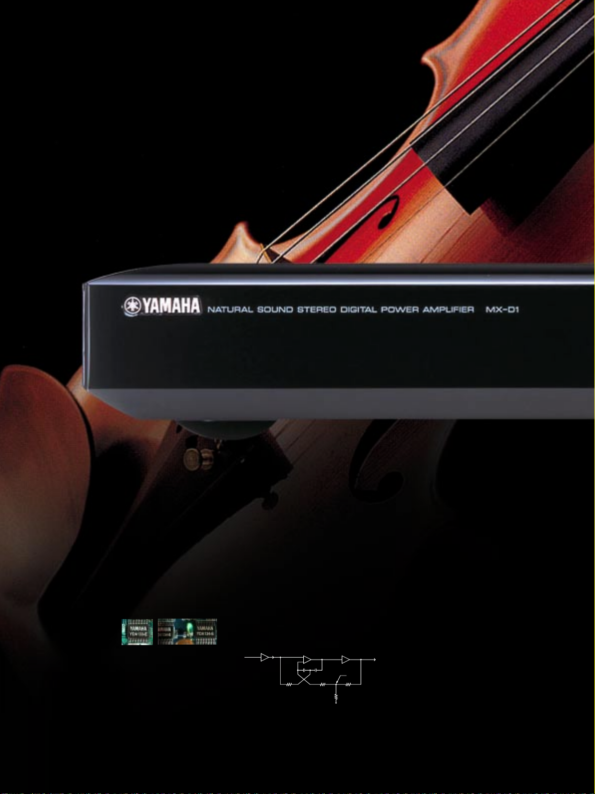
YDA133 Modulator LSI and two
YDA134 Power MOS-FET Drive LSIs
Constant Gain PLL Modulator Circuit
This circuit eliminates the dependency of the
output signal on power voltage fluctuation by
using the YDA133 modulator LSI, which combines a
PLL circuit with a modulator circuit. The modulator
circuit operates synchronously with a standard
clock to provide a PWM output waveform at a
fixed frequency of 352.8kHz, based upon two types
of input information: the input music signal level
and the output voltage at the power supply stage
(+/-B). A synchronized multi-channel amplification
system can be used without a carrier frequency
beat for bi-amplification or a multi-channel home
theater system with a backup amplifier.
Digital Cross Feedback Loop Circuit
The digital pulse output is fed back by the Digital
Cross Feedback Loop, improving the linearity of the
output stage and of the modulator circuit. This
achieves superior low distortion characteristics and
high dynamic range. In order to achieve higher
negative feedback, the MX-D1 uses two CR filters.
Cross Feedback Loop
Block Diagram
Advanced Analog Feedback
The 352.8kHz carrier signal is removed by the fc
30kHz output LC filter, and forwarded negative
feedback is added to achieve amplification over a
wide bandwidth of 100kHz and with a high
damping factor (over 200), without load impedance
dependency.
Active Power Control System
The maximum output of a conventional amplifier is
determined in most cases by the power voltage clip
level. The Active Power Control System detects the
output current to control the voltage limiter value
in order to independently control the continuous
maximum output and dynamic power at load
impedance values of 2—8 ohms. This system makes
it possible to continually provide the amplifier’s
maximum performance at speaker load.
Direct Drive High-Efficiency Power Supply and
Magnetic Coupling Rectification Circuit
The power circuit is equipped with the newest
version of the Yamaha patented voltage/current
drive resonance type switching power source, which
achieves low noise performance while retaining
high efficiency. The secondary rectification circuit
is a magnetic coupling rectification circuit that
efficiently handles power damping. This circuit
 Loading...