

Page 1

MTX Editor
User’s Manual
MTX Editor is software for connecting, constructing, and controlling a system that uses MTX series,
XMV series, and EXi8/EXo8 units. The settings you make in MTX Editor are sent to the MTX series,
XMV series, and EXi8/EXo8 units that are connected via Ethernet.
After the settings have been sent, the system will operate without a computer.
A control panel such as a DCP series unit can also be used to control the system in real time.
Notice regarding data copyright
Music and sound data sold or provided by Yamaha Corporation or a third party may not be copied
or reused without permission from the copyright owner, with the exception of copying for personal
use to the extent permitted by law. Before using this data, please obtain permission from the
copyright owner, or consult a copyright specialist.
Notice regarding the content of this user’s manual
● All copyrights for this software and user’s manual are the property of Yamaha Corporation.
● Unauthorized copying or modification of this software or user’s manual in part or in whole is
prohibited.
● Please be aware that Yamaha Corporation accepts no responsibility for any results or
consequences that may follow from the use of this software and user’s manual.
● All of the illustrations and screen shots in this user’s manual are provided for the purpose of
explaining the operation. For this reason, they may differ from the actual specifications.
● Changes in the system software, the functionality, and the specifications that may result from
updates to the application will be dealt with in a separate leaflet or manual.
● Ethernet is a trademark of the Xerox Corporation.
● Windows is a registered trademark of Microsoft Corporation USA in the United States and in
other countries.
● Bonjour is a trademark of Apple Inc. registered in the United States and in other countries.
● The SDHC logo and the SD logo are trademarks of SD-3C, LLC.
● MPEG Layer-3 audio coding technology licensed from Fraunhofer IIS and Thomson.
● Company names and product names appearing in this document are the trademarks or
registered trademarks of their respective owners.
MTX Editor User’s Manual
1
Page 2

Contents
Notice regarding data copyright .................1
Notice regarding the content of
this user’s manual ......................................1
Chapter 1. An overview of MTX Editor .............4
An audio system control network ...............4
Terms used in this user’s manual.................4
Data handled by MTX Editor....................... 6
Connection requirements for
an MTX system .......................................... 7
MTX system configuration examples...........8
What are YDIF connections?
(Cascade mode and Distribution mode) ....9
What are Dante connections?
(Daisy-chain connection and
Star connection).......................................12
Chapter 3. Project screen................................30
❏ System selection tabs ...........................................30
Network devices .........................................31
MTX system ................................................32
❏ “Device Configuration Wizard” dialog box........33
❏ YDIF-connected devices ......................................42
❏ Digital control panel............................................43
❏ Analog-connected devices ...................................44
❏ DANTE-connected devices.................................. 45
[System] tab .............................................. 46
[Device] tab ............................................... 47
[Alert] tab ................................................. 49
Chapter 4. System screen................................50
❏ Daisy-chain connection....................................... 12
❏ Star connection.................................................... 12
❏ About redundant networks................................. 13
Patching .................................................... 14
Workflow ...................................................16
About the screens ......................................23
❏ Project screen ...................................................... 23
❏ System screen ...................................................... 23
Moving between screens............................24
Chapter 2. Menu bar and tool buttons...........25
Title bar......................................................25
Menu bar ....................................................25
Tool buttons.............................................. 28
“MAIN” screen ............................................53
❏ “Input Patch” dialog box.....................................62
❏ “Output Patch” dialog box ..................................63
“INPUT” screens ........................................ 64
“MATRIX” screen....................................... 74
“ZONE” screen ........................................... 78
“ROUTER” screen ....................................... 82
“OUTPUT” screens ..................................... 84
“EFFECT” screen......................................... 92
“DCA” screen..............................................94
“MY4-AEC” screen ..................................... 96
❏ “To Far-end” screen.............................................99
❏ “Near-end Voice” screen ...................................100
❏ “Mic” screen.......................................................101
“EXT. I/O” screen .................................... 102
MTX Editor User’s Manual
2
Page 3

Contents
❏ “YDIF” screen (Distribution mode) ................. 102
❏ “YDIF In Patch” dialog box .............................. 105
❏ “YDIF Out Patch” dialog box ........................... 105
❏ “Channel Select” dialog box.............................. 106
❏ “YDIF” screen (Cascade mode) ........................ 107
❏ “ANALOG” screen ............................................ 108
❏ “Line Out Patch” dialog box ............................. 109
❏ “DANTE” screen ............................................... 110
❏ “Dante In Patch” dialog box ............................. 111
❏ “Dante Out Patch” dialog box .......................... 111
“XMV” screen .......................................... 112
❏ “XMV Patch” dialog box................................... 114
“EXo8” screen.......................................... 115
❏ “EXo Patch” dialog box..................................... 116
Chapter 7. Dialog boxes................................138
❏ “Startup” dialog box ..........................................138
❏ “Network Setup” dialog box ..............................139
❏ “Device Information” dialog box ......................140
“Update Firmware” dialog box .........................142
“IP Address” dialog box .................................... 144
❏ “MTX Configuration” dialog box .....................146
❏ “Dante Information” dialog box .......................149
❏ “Word Clock” dialog box ..................................150
❏ “Clock” dialog box ............................................. 152
❏ “Daylight Saving Time” dialog box...................154
❏ “Scheduler” dialog box ......................................155
❏ “Remote Control” dialog box............................163
❏ “Digital Control Panel” dialog box ...................164
❏ “Wireless DCP” dialog box ...............................168
Chapter 5. Online and Synchronization........117
Online .......................................................117
❏ “Synchronization” dialog box........................... 117
❏ “Go online – From devices” dialog box ............ 120
Synchronization ...................................... 121
Chapter 6. Presets .........................................123
❏ “Preset” dialog box............................................ 123
“Settings” dialog box......................................... 127
■ “GPI Out” dialog box .....................................................129
■ “SD Play” dialog box.......................................................130
Recall Filter setting screen ................................ 133
❏ “GPI” dialog box................................................169
❏ “GPI Calibration” dialog box............................171
❏ “Security Settings” dialog box ...........................172
❏ “Project Information” dialog box .....................174
❏ “Configuration Diagram” dialog box ...............175
❏ “Get Log” dialog box..........................................176
❏ “Sampling Rate Converter” dialog box............. 177
Appendix ..................................................178
Channel list ..............................................178
List of settings in “Settings”
dialog boxes .......................................... 179
■ Switch...............................................................................179
■ Knob/Slider ..................................................................... 185
■ GPI Input......................................................................... 187
■ GPI Output...................................................................... 191
Alert list .................................................. 195
Troubleshooting...................................... 200
MTX Editor User’s Manual
3
Page 4

Chapter 1. An overview of MTX Editor
An audio system control network
When multiple MTX series, XMV series, and EXi8/EXo8 units are connected via Ethernet as a
network, they will operate together as a single audio system. This is called an “MTX system,” and a
space containing multiple MTX systems is called a “project.” If a computer is connected to the network,
the computer can control the MTX system via the MTX.
Terms used in this user’s manual
● YDIF
This is a digital audio transmission format that uses Ethernet cables to send and receive
up to 16 channels of audio and word clock. YDIF makes it easy to connect MTX units
to share buses and expand the number of input/output channels (Cascade mode), or to
connect XMV and EXi8/EXo8 units so that digital audio signals can be conveyed
without deterioration (Distribution mode).
This format does not include control signals. To send and receive control signals, you
must separately connect the NETWORK connectors.
● Dante
This is a digital audio transmission format developed by the Audinate Corporation that
uses Ethernet cables to send and receive up to 1024 channels of audio together with
word clock and control signals. An MTX system can use up to 64 channels, and there
can be a maximum of 256 channels for the entire project.
● UNIT ID
This is a unique ID assigned to an MTX or XMV unit. It must not conflict between
units.
The unit ID is specified on the rear panel of each unit.
● Panel ID
This is a unique ID assigned to a DCP. It must not conflict within the group of DCP
units connected to the same MTX.
The panel ID is specified for each DCP.
● Components and parameters
Audio processing modules such as equalizers and compressors are called
“co mp on en ts .”
Editable elements of a component are called “parameters.”
● Configuration
This is the basic group of parameters, which you will set first in MTX Editor. Here you
will specify how audio is patched between the MTX and the other external devices.
These settings are not included in a preset file.
● Preset
A preset is a set of parameters. Presets can be recalled from a DCP or wireless DCP, via
GPI, from an MTX unit, or from MTX Editor.
Fifty presets can be stored in an MTX system.
MTX Editor User’s Manual
4
Page 5

Terms used in this user’s manual Chapter 1. An overview of MTX Editor
● Emergency mode
If the “Preset” dialog box’s [Emergency Recall] setting is [ON], the MTX will enter this
mode when it receives an EMG (Emergency) signal from an external device, or when
the input to the +24V [GPI IN] pin (IN 8 for the MTX3, or IN 16 for the MTX5-D) falls
below 2.5V. In this mode, the unit will operate as follows.
• The current state will be remembered. This remembered state is used to return to the
original state when the unit exits Emergency mode.
• The preset specified by the “Preset” dialog box’s [Emergency Recall] setting will be
recalled.
• Operations from an external controller such as a DCP will no longer be received.
• The unit will be taken offline from MTX Editor.
• All MTX units in the same MTX system will enter Emergency mode.
MTX Editor User’s Manual
5
Page 6

Data handled by MTX Editor Chapter 1. An overview of MTX Editor
NOTE
Data handled by MTX Editor
Project file (.mtx)
Configuration
Device structure
The type and number of devices, their UNIT ID, and YDIF connection order
*1
MTX system settings
YDIF mode
Device name
“Preset” dialog box
“Security Setting” dialog box ([File] menu)
“Project Information” dialog box ([File] menu)
Contents of “Set IP Address” in the “Device Information” dialog box ([System]
menu)
“MTX Configuration” dialog box ([System] menu)
“Daylight Saving Time” dialog box ([System] menu)
“Scheduler” dialog box ([System] menu)
“GPI” dialog box ([System] menu)
“Remote Control” dialog box ([System] menu)
Library of the “Digital Control Panel” dialog box ([Controller] menu)
Library of the “Wireless DCP” dialog box ([Controller] menu)
Dimmer on/off ([Device] tab)
Patching in the “EXT. I/O” screen between the MTX and external devices (YDIF
connections, analog connections, Dante connections)
*1 Synchronization is not possible if the device configuration is different.
*2 This will not change even if the preset is switched.
Preset
MTX sources for YDIF in the “EXT. I/O” screen
Parameters for MTX components
Assignments to DCP library presets
Assignments to Wireless DCP library presets
GPI Out status
[SD Song Select & Play]
Parameters of external devices
MY4-AEC parameters (except for AES/EBU)
*2
Speaker Processor Library (.ce3)
Even if you modify the configuration, the changes will not be reflected in previously-stored
presets. After modifying a configuration, you must (if necessary) recall the preset and then
store it again.
MTX Editor User’s Manual
6
Page 7

Connection requirements for an MTX system Chapter 1. An overview of MTX Editor
Project
MTX system
MTX system
Audio connections
(up to a total of 20 units)
DCP (up to 8 units per MTX unit)
Wireless DCP
(up to 8 units per MTX unit)
Control panel
Line
(analog)
connections
YDIF connections
(up to 4 MTX units,
up to a total of
8 units)
MTX system
MTX system
Dante
connections
Connection requirements for an MTX system
The requirements for an MTX system are as follows.
Overall MTX system (1 in diagram below)
• The XMV is controlled from MTX Editor via the MTX
• A maximum total of 20 devices such as MTX or XMV units can belong to one MTX
system
• Only one computer at a time can access the MTX system
Devices connected to each other via YDIF connection (2 in diagram below)
• Maximum total of eight units (maximum of four MTX units)
• At least one MTX unit must be included
Control panels connected to the MTX (3 in diagram below)
• For each MTX unit, there can be a maximum of eight digital control panels (DCP)
belonging to the MTX system
• For each MTX unit, there can be a maximum of eight wireless DCP units belonging
to the MTX system
Control panels connected via analog to the MTX (4 in diagram below)
• A maximum of 20 units for the entire MTX system, including the XMV units
included here
Devices connected to the MTX via Dante (5 in diagram below)
• A maximum of 20 units for the entire MTX system, including the XMV units
included here
The following diagram shows these requirements applied in MTX Editor’s Project screen.
1
2
3
MTX Editor User’s Manual
7
4 5
Page 8

MTX system configuration examples Chapter 1. An overview of MTX Editor
MTX3
MTX3
MTX3
MTX3
YDIF
XMV
YDIF connections
(diagram
2on previous page)
Analog connections
(diagram
4on previous page)
EXi8
MTX3
MTX5-D
XMV
EXo8
YDIF
YDIF connections
(diagram
2on previous page)
DCP connections
(diagram 3 on previous page)
Dante connections
(diagram
5 on previous page)
MTX system configuration examples
Example 1
Example 2
MTX Editor User’s Manual
8
Page 9

What are YDIF connections? (Cascade mode and Distribution mode) Chapter 1. An overview of MTX Editor
What are YDIF connections? (Cascade mode and Distribution mode)
An MTX system has the following two connection modes. When connecting multiple YDIF devices
(when making YDIF connections), you must choose one of these modes. In either case, the system
can easily be expanded at low cost.
Use the “Device Configuration Wizard” dialog box to switch modes.
● Cascade mode
This allows up to eight channels of matrix buses to be shared between multiple MTX
units. Mic inputs can be expanded to a maximum of 32 channels, and eight mixes can
be created.
In cascade mode, YDIF is used as the internal bus; this means that an EXi8 on the input
side and an EXo8/XMV on the output side cannot be connected via YDIF.
● Distribution mode
This is used when inputting audio signals from an EXi8 to an MTX, when inputting/
outputting between MTX units, and when outputting from an MTX to an XMV/EXo8.
This allows a single audio signal to be distributed to multiple output destinations. An
MTX and XMV can be digitally connected via YDIF to easily construct a high-quality
system.
MTX Editor User’s Manual
9
Page 10

What are YDIF connections? (Cascade mode and Distribution mode) Chapter 1. An overview of MTX Editor
01 MTX3
02 MTX3
03 MTX3
04 MTX3
YDIF1
YDIF1
YDIF1’
01 MTX3
Matrix1
ZONE1
02 MTX3
Matrix1
ZONE1
03 MTX3
Matrix1
ZONE1
04 MTX3
Matrix1
ZONE1
YDIF1 YDIF1’
01 MTX3
Matrix1
ZONE1
02 MTX3
Matrix1
ZONE1
03 MTX3
Matrix1
ZONE1
04 MTX3
Matrix1
ZONE1
01 MTX3
OUT
OUT
OUT
OUT
IN
IN
IN
IN
02 MTX3
03 MTX3
04 MTX3
Up to four MTX units can be connected.
Eight channels of signals can be
shared by the buses.
Shared signals are used as inputs
to the zones.
Eight channels of signals can be
shared by the buses.
If CASCADE mode is off, the unit’s
own mix is used as the input to the zone
(this can be specified for each unit).
No output
No output
No output
No output
02 MTX3 : Matrix1
CASCADE MODE = OFF
Connection
YDIF MODE = DISTRIBUTION
YDIF MODE = CASCADE
To switch the settings of the two modes,
click the [System] menu command
“MTX Configuration” and make settings for each matrix.
RING connection
If only MTX units are connected
Use the [Device Configuration Wizard]
to switch both settings.
There are 16 channels of audio signal
in Distribution mode.
The audio will circulate, but an
intermediary MTX unit can replace
the signal.
Through
Through
Through
Through
02 MTX3 : Matrix1
CASCADE MODE=ON
YDIF patching is done
in the
“
EXT. I/O” screen.
10
MTX Editor User’s Manual
Page 11

What are YDIF connections? (Cascade mode and Distribution mode) Chapter 1. An overview of MTX Editor
If MTX units and other YDIF units are connected
Connection
RING connection
01 EXi8
02 MTX5-D
03 MTX3
04 XMV4280
05 EXo8
Up to eight units can be connected via YDIF.
Cascade mode Distribution mode
If a device other than an MTX is
connected, it is not possible to
select Cascade mode.
YDIF patching is done in the “EXT. I/O” screen.
YDIF1
Through
IN
Through
YDIF1
IN
<Example of using Distribution mode>
8CH
EXi8
4CH
4CH
8CH
8CH
8CH
4CH
4CH
EXi8
MTX3
YDIF1–8
YDIF9–16
YDIF1–4
01 EXi8
02 MTX5-D
03 MTX3
04 XMV4280
05 EXo8
No output
Through
No output
Through
No output
Through
Through
There are 16 channels of audio signal in Distribution mode.
The audio will circulate, but an intermediary MTX unit can replace the
signal.
The XMV is only able to receive.
When connected via YDIF, the XMV will send the audio signals without
change to the EXi8 or the MTX. If the input from the EXi8 has not been
specified in the “YDIF In Patch” dialog box, the audio signals that have
passed through the XMV/EXo8 will return to the MTX.
In this case, make settings in the “Input Patch” dialog box so that YDIF
is not assigned to input channels; this prevents the returned audio
signals from being mixed.
OUT
IN
OUT
IN
OUT
IN
OUT
01 MTX3
02 MTX3
03 MTX3
04 XMV4280
No output
Through
No output
Through
No output
Through
OUT
IN
OUT
IN
OUT
IN
OUT
YDIF5–8
YDIF9–12
YDIF13–16
4CH
4CH
4CH
4CH
XMV
XMV
XMV
XMV
11
MTX Editor User’s Manual
Page 12

What are Dante connections? (Daisy-chain connection and Star connection) Chapter 1. An overview of MTX Editor
SECONDARY
PRIMARY
Computer
PRIMARY
SECONDARY
PRIMARY
What are Dante connections? (Daisy-chain connection and Star connection)
A Dante network can be connected in two ways.
Set the DIP switches of the devices as appropriate for the type of connection.
❑ Daisy-chain connection
In a daisy-chain connection, each device is connected to the next device, in a chain. This method
makes it simple to construct a network, and does not require a network switch. Use this method for
simple systems in which a relatively small number of units are to be connected.
As the number of connected units increases, you will need to increase the latency. Also, if a problem
such as a broken cable occurs, the network will be disconnected at that point, and communication
with units beyond that point will be impossible.
❑ Star connection
In a star connection, devices are connected with a network switch at their center. By using a network
switch that supports gigabit Ethernet, you can create even large-scale networks that require high
bandwidth. We recommend that you use a network switch that supports functionality for
controlling and monitoring the network (e.g., QoS, which gives priority to clock synchronization
and audio transmission for specified data routings).
With this type of connection, it is typical to create a redundant network so that audio will continue
being conveyed even if a problem occurs with the network.
12
MTX Editor User’s Manual
Page 13

What are Dante connections? (Daisy-chain connection and Star connection) Chapter 1. An overview of MTX Editor
NOTE
Network switch A
Network switch B
PrimaryDante
SecondaryDante
❑ About redundant networks
A redundant network is a network consisting of two circuits: a primary circuit and a secondary
circuit. Normally, communication occurs on the primary circuit, but if a problem such as a broken
cable occurs on the primary circuit, communication will automatically switch to the secondary
circuit. By using this type of connection with a star connection, you can construct an environment
that is more resistant to network problems than a daisy-chained network.
In order to communicate with MTX Editor or a Wireless DCP when operation has switched to
the secondary Dante connection, you must re-connect the computer or Wi-Fi access point to
the secondary Dante network switch.
13
MTX Editor User’s Manual
Page 14
Patching Chapter 1. An overview of MTX Editor
Input to the MTX
Output from the MTX
Patching
In a digital audio network such as YDIF or Dante that comprises the MTX system, you will make
settings on the transmitting device to specify “which output channel/bus’s signals will be sent to
which channels of the digital audio network,” and make settings on the receiving device to specify
“which channels of the digital audio network will be received on which input channels.”
This type of patching mechanism allows the signal of one channel of the digital audio network to
be received by multiple devices.
In MTX Editor, transmission/reception settings for the MTX unit are made in the “MAIN” screen,
and transmission/reception settings for external devices such as the XMV or EXi8 are made in the
“EXT. I/O” screen.
Settings for connecting the MTX’s analog output to the XMV’s analog input are also made in the
“EXT. I/O” screen.
By making settings for external devices in the “EXT. I/O” screen, the parameters of an external
device can be edited in the parameter edit screen that appears when you click the port/external
device parameter recall button in the “MAIN” screen.
• Settings on the MTX unit itself (the screen of the MTX5-D is shown)
14
MTX Editor User’s Manual
Page 15

Patching Chapter 1. An overview of MTX Editor
Transmission from an external device to
YDIF or Dante
Transmission from YDIF or Dante to an external device
Settings for the analog connectors of the XMV
Input channel parameter
editing screen
Output channel
parameter
editing screen
• Settings for external devices such as the XMV or EXi8
YDIF or Dante
Analog
• Parameter editing screen
15
MTX Editor User’s Manual
Page 16
Workflow Chapter 1. An overview of MTX Editor
NOTE
Project screen
Workflow
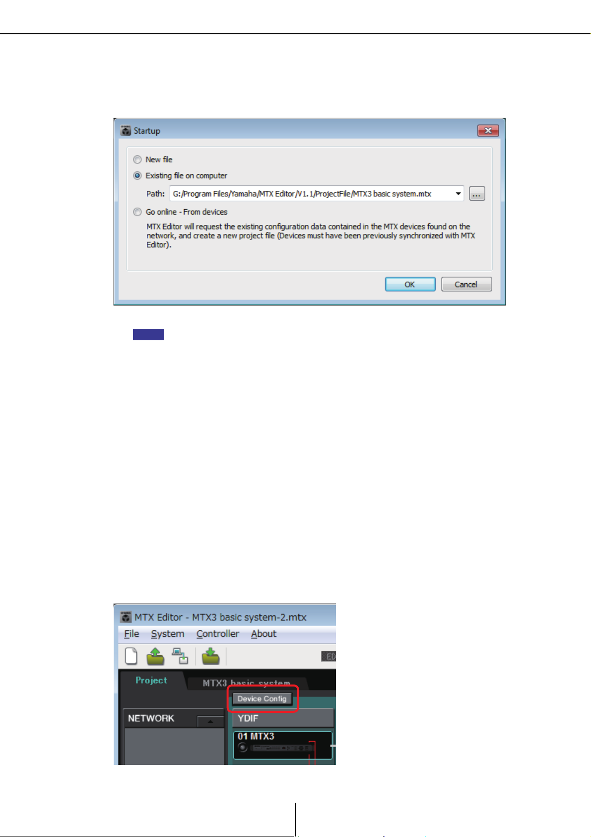
Start MTX Editor.
The “Startup” dialog box will appear.
When you select [New file], the “Device Configuration Wizard” dialog box will appear.
When you install MTX Editor, a project file linked with the “MTX Setup Guide” will be installed
in the following folder.
● For a 32-bit OS
C:/Program Files/Yamaha/MTX Editor/V*.*/ProjectFile
● For a 64-bit OS
C:/Program Files(x86)/Yamaha/MTX Editor/V*.*/ProjectFile
*.* will be the version of the installed MTX Editor.
You can also select and use this file by selecting [Existing file on computer].
Follow the screens of the “Device Configuration Wizard” dialog box to specify the
configuration of the MTX system.
For details about the “Device Configuration Wizard” dialog box when creating a new
configuration, refer to the “MTX Setup Manual.”
Specify the configuration of the MTX system as directed in the screens. The device
configuration will be shown in the Project screen. You’ll be able to print a configuration
diagram at the end of the wizard.
If you canceled the procedure before completing the “Device Configuration Wizard,” or if
you want to change the configuration of the MTX system, click the [Device Config]
button. The “Device Configuration Wizard” dialog box will appear once again.
16
MTX Editor User’s Manual
Page 17
Workflow Chapter 1. An overview of MTX Editor
EXT. I/O screen
MAIN screen
For details, refer to Project screen.
Change the functions of the MTX.
To change the functions of input ports and stereo input channels, use the “MTX
Configuration” dialog box, which can be opened from the [System] menu.
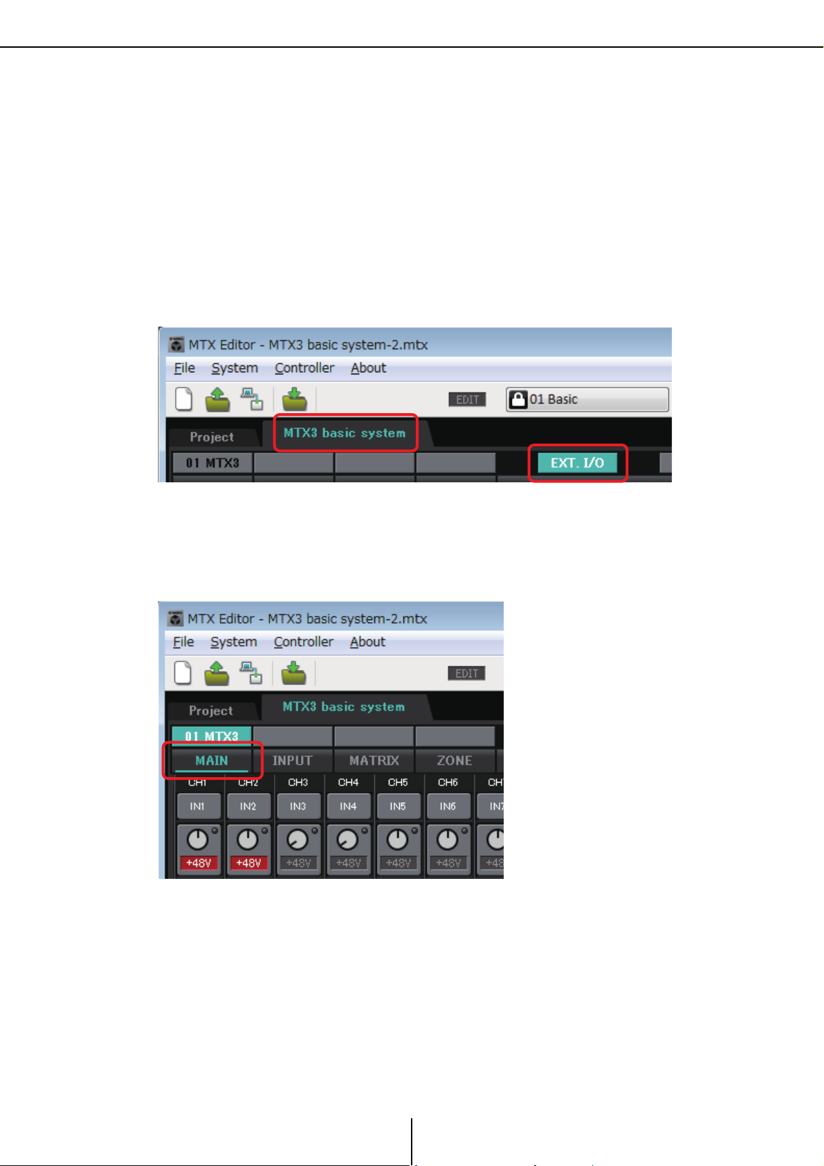
Specify the patching between the MTX and the peripheral devices.
You’ll make these settings in the “EXT. I/O” screen. To access the “EXT. I/O” screen, click
the [EXT. I/O] button in the System screen.
In the System screen, click the [MAIN] button to access the “MAIN” screen.
For details, refer to “MAIN” screen.
17
MTX Editor User’s Manual
Page 18

Workflow Chapter 1. An overview of MTX Editor
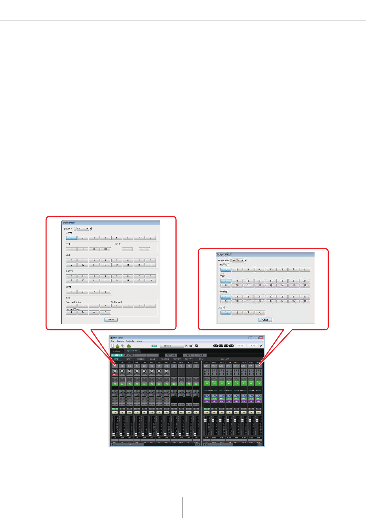
“Input Patch” dialog box
Port select
buttons
Specify the MTX’s input channel settings.
Use the “Input Patch” dialog box to assign ports to input channels. To open the “Input
Patch” dialog box, click a port select button in the MAIN screen.
For details, refer to “Input Patch” dialog box.
In the same way, use the “Output Patch” dialog box to assign ports to output channels.
Edit the component parameters.
To access each component editing screen, click the buttons indicated below.
For details on each component, refer to the following screens.
“INPUT” screens
“MATRIX” screen
“ZONE” screen
“ROUTER” screen
“OUTPUT” screens
“EFFECT” screen
“DCA” screen
18
MTX Editor User’s Manual
Page 19
Workflow Chapter 1. An overview of MTX Editor
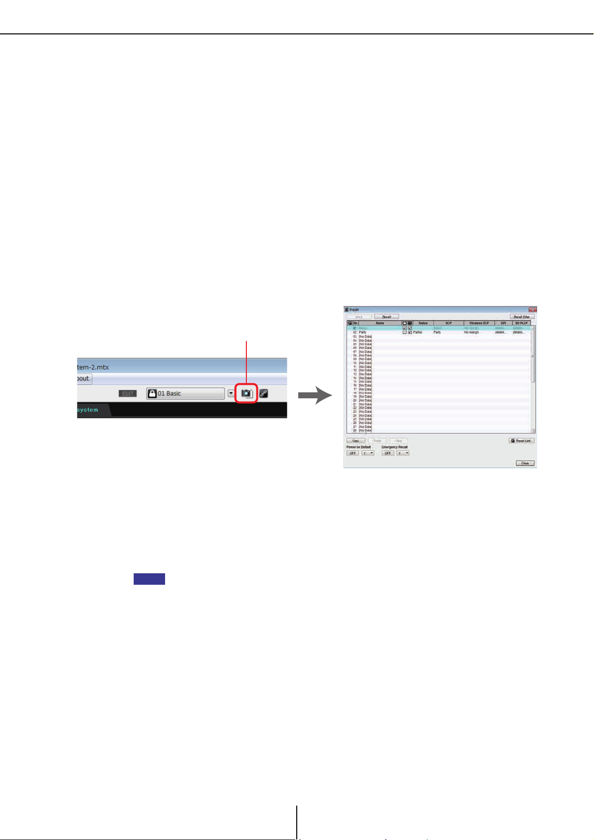
“Preset” dialog box
Preset button
NOTE
Make DCP, Wireless DCP, GPI, and Scheduler settings.
You’ll make these settings in the following dialog boxes.
DCP settings: “Digital Control Panel” dialog box
(On the [Controller] menu, click [Digital Control Panel].)
Wireless DCP settings: “Wireless DCP” dialog box
(On the [Controller] menu, click [Wireless DCP].)
GPI settings: “GPI” dialog box or “GPI Calibration” dialog box
(On the [System] menu, click [GPI] or [GPI Calibration].)
Schedule settings: “Scheduler” dialog box
(On the [System] menu, click [Scheduler])
Store the preset.
You’ll use the “Preset” dialog box to store the preset. To open the “Preset” dialog box, click
the preset button.
For details on the DCP library, Wireless DCP library, and audio file settings that are
recalled at the same time as a preset, refer to “Preset” dialog box.
Connect your devices as shown in the configuration diagram you printed.
Turn off the power of each device, and set the UNIT ID on the rear panel of the
MTX, XMV, and EXi8/EXo8 units.
You can also print the configuration diagram by clicking [Print Configuration Diagram] on the
[File] menu.
First make sure that DIP switch 6 (IP SETTING) on the unit’s rear panel is set to [UNIT
ID]. If it is set to [PC], change it to [UNIT ID] and then restart the device.
Use the rear panel [UNIT ID] rotary switch and DIP switches to set the UNIT ID of each
device. In MTX Editor, the UNIT ID is shown as a hexadecimal number. Use the DIP
switches (switches 1–2 on the MTX and EXi8/EXo8, switches 1–3 on YDIF-equipped
models of XMV) to specify the upper digit, and use the [UNIT ID] rotary switch to specify
the lower digit. On Dante-equipped models of XMV, use the [UNIT ID] rotary switch
[HIGH] to specify the upper digit, and use [LOW] to specify the lower digit.
Do not set the UNIT ID to 00.
19
MTX Editor User’s Manual
Page 20

Workflow Chapter 1. An overview of MTX Editor
0A
DIP switch
[UNIT ID]
Rotary Switch
3
ON
3
3
ON
3
3
3
ON
3
3
3
3
ON
3
3
3
3
3
ON
3
3
3
3
3
3
3
3
3
3
3
3
3
3
3
3
3
3
3
3
3
NOTE
Example setting) Setting the UNIT ID to [0A] on YDIF-equipped models of XMV
Use the DIP switch combinations shown below to specify the upper digit of the UNIT ID.
Upper digit is 0
Upper digit is 1
Upper digit is 2
Upper digit is 3
Upper digit is 4
Upper digit is 5
Upper digit is 6
Upper digit is 7
If you want to use a DHCP server or operate the device with a fixed IP address, refer to “IP
Address” dialog box. To open the “Set IP Address” dialog box, use the “Device Information”
dialog box which you can access from the [System] menu.
20
MTX Editor User’s Manual
Page 21

Workflow Chapter 1. An overview of MTX Editor
NETWORK connector of
the MTX3
NETWORK connector of a
YDIF-equipped model of XMV
[Dante] connector of a Danteequipped model of XMV
[Dante] connector of
the MTX5-D
NETWORK connector of
the EXi8/EXo8
Connections with the
devices has succeeded
Connect the devices and your computer as shown in the configuration diagram.
Connect the device to the computer using its [Dante] connector for a Dante-equipped unit
or its NETWORK connector for a YDIF-equipped unit. Normally you will connect the
devices to the computer via a network switch. Only in the case of Dante-equipped models
when using a daisy-chain connection, you will connect the units to the computer in a
daisy-chain. If there is only one MTX unit, you can also connect the computer directly to
the MTX.
Turn on the power of the device.
Select the network card and specify the IP address of the computer.
To select the network card, use the “Network Setup” dialog box which you can access from
the [System] menu. If no DHCP server is connected, set the IP address of the network card
to a fixed IP address. The IP address setting for the network card is made in Control Panel
“Network Connections.” You can access “Network Connections” by clicking the [Open
Network Connections] button in the “Network Setup” dialog box.
When connections have been established between the computer and the devices, the
device icons shown in the Project screen will change.
Verify that the firmware versions of the devices are compatible with MTX
Editor.
For details, refer to the “Device Information” dialog box which you can access from
the [System] menu.
For information about firmware compatibility with MTX Editor, refer to the Yamaha
Pro Audio website.
http://www.yamahaproaudio.com/japan/ja/
21
MTX Editor User’s Manual
Page 22
Workflow Chapter 1. An overview of MTX Editor
NOTE
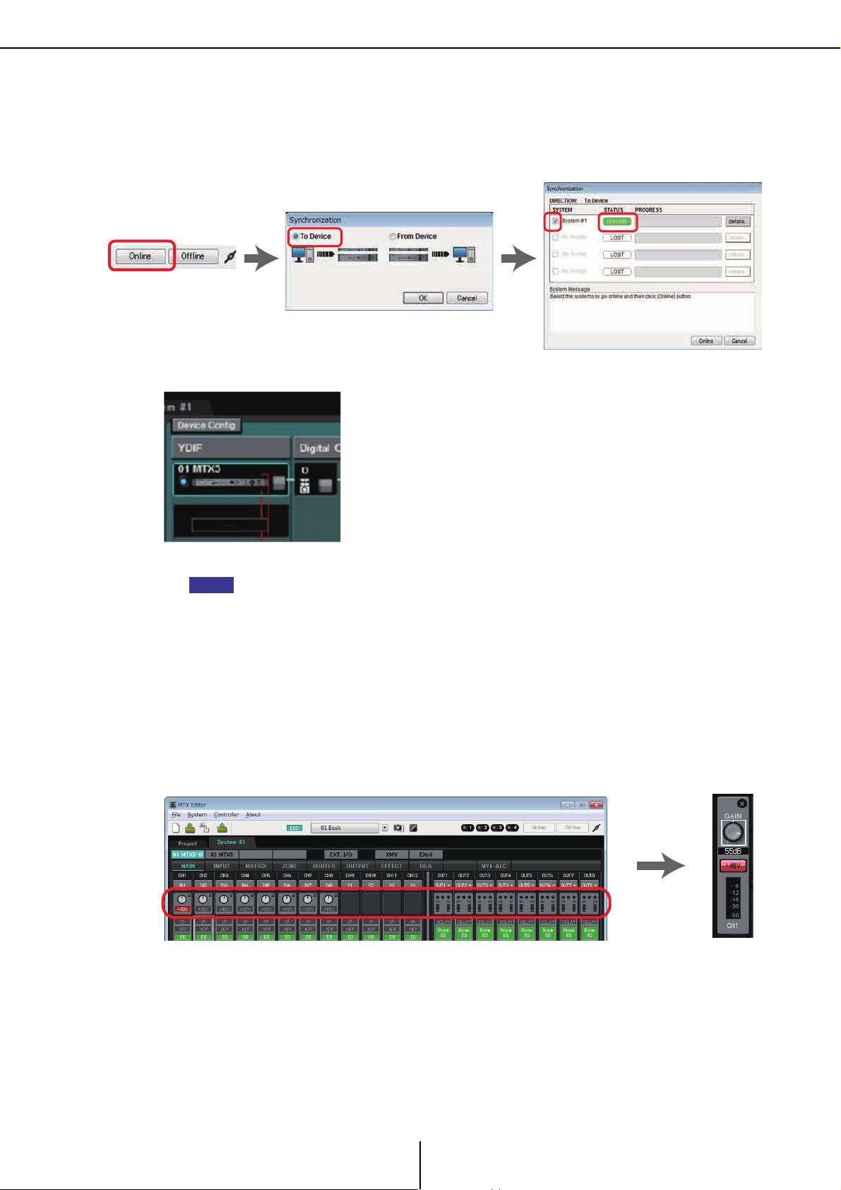
Synchronize your computer and the devices (put them in the online state).
Click the [Online] button in the toolbar to open the “Synchronization” dialog box, check
“To Device”, and click the [OK] button.
When the dialog box indication has switched, select the check box of the system that you
want to place online, and click the [Online] button.
In the online state, the indicator will light blue as shown below.
When online, the computer’s time will be sent to each device.
The Daylight Saving Time setting will reflect the “Date and Time” settings of the computer that
was used to first create the applicable project file. If you want to change the Daylight Saving
Time settings of a project file that was created on a computer for which Daylight Saving Time
was not enabled, or a computer with a different time zone setting, open the “Daylight Saving
Time” dialog box from the [System] menu and change the settings.
Edit the MTX’s ports and the XMV’s parameters
If you assigned channels of an external device or ports of an MTX unit to channels when
making internal MTX patch settings as described above, you can click the parameter recall
button of that port or external device to open an edit screen for those parameters.
For details, refer to “MAIN” screen.
Save the project file.
On the [File] menu, click [Save] or [Save As] to save the project file.
If you want to apply security settings to the file, you can specify a PIN code in the “Security
Settings” dialog box which you can open from the [File] menu.
22
MTX Editor User’s Manual
Page 23

About the screens Chapter 1. An overview of MTX Editor
About the screens
MTX Editor consists mainly of the Project screen and the System screen.
❑ Project screen
In this screen you can manage the MTX system. You can check the status of the MTX and XMV
units, and make device-related settings. You can also check devices that have generated an alert.
❑ System screen
In this screen you can make channel, matrix, and effect settings.
23
MTX Editor User’s Manual
Page 24

Moving between screens Chapter 1. An overview of MTX Editor
Project screen
System screen
(“MAIN” screen)
SYSTEM tab [Project] tab
Toolbar or menu
Dialog boxes (*1)
[EXT. I/O] button
“EXT. I/O” screen
[MATRIX] button
[INPUT] button
[ROUTER] button [EFFECT] button
[DCA] button
“MATRIX” screen
“INPUT” screens “ZONE” screen
“ROUTER” screen “EFFECT” screen
“DCA” screen
Toolbar or menu
“XMV” screen “EXo8” screen
[XMV] button [EXo8] button
[MY4-AEC] button (*2)
“MY4-AEC” screen
“OUTPUT” screens
[ZONE] button [OUTPUT] button
Moving between screens
(*1)The “Device Configuration Wizard” dialog box can be opened only from the Project screen.
(*2)Not shown if the MY4-AEC is not selected for the MTX5-D in the “Device Configuration
Wizard” dialog box.
24
MTX Editor User’s Manual
Page 25

Chapter 2. Menu bar and tool buttons
Tool buttons
Title barMenu bar
This chapter provides an overview of the menu bar and the tool buttons. For details on the various
dialog boxes, see the linked references.
Title bar
This will indicate “MTX Editor.”
The name of the currently open project file is shown at the right of this. If you have opened a new
project file or if the project file has never been saved, nothing will be shown here.
Menu bar
The commands that can be executed by MTX Editor can be found here, grouped by category.
Click here to see a list of commands.
25
MTX Editor User’s Manual
Page 26
Menu bar Chapter 2. Menu bar and tool buttons
Menu Command Summary
Creates a new project file.
[New]
[Open]
[Go Online –
From Devices]
[Save]
If you are currently editing a project file, a
confirmation message will appear.
This command is not available while online.
Opens a saved project file.
If you are currently editing a project file, a
confirmation message will appear.
This command is not available while online.
Loads the settings of the MTX system into MTX
Editor.
You can use this command if you have lost the setup
file of the MTX system.
If you are currently editing a project file, a
confirmation message will appear.
This command is not available while online.
Saves the project file (overwriting the previous
version of the file).
The first time you save, the “Save File” dialog box will
appear; specify a name for the file and save it.
This command cannot be selected if you are logged
on as Guest user.
Dialog box that
appears
“Device Configuration
Wizard” dialog box
“Open File” dialog box
“Go online – From
devices” dialog box
–
[File]
[Save As]
[Security]
[Project
Information]
[Print
Configuration
Diagram]
[Recently
Opened Files]
[Log Off]
[Exit]
Saves the project file as a different file. When you
choose this command, the “Save File” dialog box will
appear.
Specifies security settings to prevent a guest user
from making and saving changes to the system.
These settings are saved in the project file.
Allows you to include a memo in the project file to
record property information or contact information.
A guest user can only view this.
Displays a diagram that shows how devices such as
the MTX, XMV, and DCP are connected. The
configuration diagram can be printed.
Lists up to five most recently used project files,
allowing you to open them.
This command is not available while online.
If you want to log on with a different account, choose
this command to log off first.
This command is unavailable if [Security] is turned
off in the “Security Settings” dialog box, or if you are
online.
Exits MTX Editor.
If the project file has been edited, a confirmation
message will appear.
This command is not available while online.
“Save File” dialog box
“Security Settings”
dialog box
“Project Information”
dialog box
“Configuration
Diagram” dialog box
–
“Log on” dialog box
–
26
MTX Editor User’s Manual
Page 27
Menu bar Chapter 2. Menu bar and tool buttons
Menu Command Summary
Selects the computer’s network adapter that will be
[Network
Setup]
[Device
Information]
[MTX
Configuration]
[Dante
Information]
[Word Clock]
[System]
[Clock]
[Daylight
Saving Time]
used to communicate with the MTX.
You can also change the IP address of the network
adapter.
Lists the devices on the network, allowing you to
update their firmware and change their IP address.
Here you can specify input/output settings for each
device, such as MTX input ports, output channels,
and matrix buses.
This command is not available in the Project screen.
Indicates the Dante settings and firmware version.
Here you can also make settings for bit rate and
latency.
Specify the project’s word clock master and word
clock settings.
Regardless of the online/offline state, the time and
date will be updated for all devices connected to the
same network.
Specifies the Daylight Saving Time setting.
Dialog box that
appears
“Network Setup”
dialog box
“Device Information”
dialog box
“MTX Configuration”
dialog box
“Dante Information”
dialog box
“Word Clock” dialog
box
“Clock” dialog box
“Daylight Saving Time”
dialog box
[Controller]
[About]
Switches presets or plays back a song or sound
effect from an SD memory card at a previously
[Scheduler]
[GPI
Calibration]
[GPI] Makes GPI input/output settings. “GPI” dialog box
[Remote
Control]
[Digital Control
Panel]
[Wireless DCP]
[About MTX
Editor]
specified date and time. Each such setting is called
an “Event.” You can make event settings in the
“Scheduler” dialog box.
Calibrates the input voltage detection range for the
[GPI] connector of the MTX unit. (Available only
when online.)
Makes settings for the [RS-232C] connector.
Makes settings for the digital control panel (DCP).
Makes settings for the “Wireless DCP” iOS
application.
Except for templates, the items that can be set are
the same as for “Digital Control Panel.”
Displays details such as the software version of
MTX Editor.
“Scheduler” dialog box
“GPI Calibration”
dialog box
“Remote Control”
dialog box
“Digital Control Panel”
dialog box
“Wireless DCP” dialog
box
–
27
MTX Editor User’s Manual
Page 28
Tool buttons Chapter 2. Menu bar and tool buttons
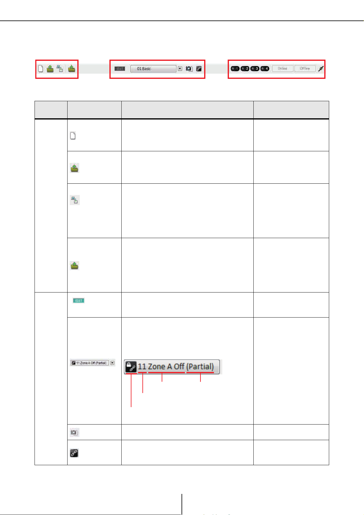
File-related tools Preset-related tools Synchronization-related tools
Preset name
Preset number
Shown only if recall
filter is specified
A chain icon is shown if preset recall is linked.
A lock icon is shown if the preset is locked.
Tool buttons
Related
tools
File
Buttons etc. Summary Dialog box that appears
Creates a new project file.
[New]
[Open]
[Go Online – From
Devices]
[Save]
[EDIT] indicator
If you are currently editing a project file, a
confirmation message will appear.
This button is not available while online.
Opens a saved project file.
If you are currently editing a project file, a
confirmation message will appear.
This button is not available while online.
Loads the settings of the currently operating
MTX system into MTX Editor.
You can use this command if you have lost the
setup file of the MTX system.
If you are currently editing a project file, a
confirmation message will appear.
This button is not available while online.
Saves the project file (overwriting the previous
version of the file).
The first time you save, the “Save File” dialog
box will appear; specify a name for the file and
save it.
This button is not available if you are logged in
as a guest user.
This indicator will light if you edit a parameter or
setting. In this case, store the preset as
necessary.
“Device Configuration
Wizard” dialog box
“Open File” dialog box
“Go online – From
devices” dialog box
–
–
The stored presets will be displayed as shown
below. (Empty presets are not shown.) The
preset you select here will be recalled.
You can overwrite-store by clicking the name of
a stored preset.
Preset
Preset select box
[Preset]
[Preset Link]
Allows you to make preset-related settings. “Preset” dialog box
Allows you to specify the preset number that will
be linked when preset recall is linked between
MTX systems.
28
MTX Editor User’s Manual
“Preset Link” dialog box
–
Page 29

Tool buttons Chapter 2. Menu bar and tool buttons
NOTE
NOTE
Related
tools
Synchronization
Buttons etc. Summary Dialog box that appears
This will light if the devices and the computer
are online. The color of the indicator will change
according to the status. The indicator is shown
Online
indicator
for each MTX system.
Blue ......when all devices assigned in the MTX
system are online.
–
Yellow ....when at least one of the devices
assigned in the MTX system is offline
Unlit ......when all devices are offline.
When you click this, the “Synchronization”
dialog box will appear, allowing you to choose
the direction of synchronization. If you click this
when online, devices that are offline will be re-
[Online]
detected, and synchronization will begin.
Nothing will happen for devices that are already
online.
If an MTX that has been assigned in the
“Device Configuration Wizard” dialog box
is not actually connected to the network,
the [Online] button will not be available.
“Synchronization” dialog
box
When you click this, a dialog box will appear,
allowing you to choose which MTX system will
be taken offline.
[Offline]
If an MTX that has been assigned in the
“Device Configuration Wizard” dialog box
is not actually connected to the network,
the [Offline] button will not be available.
Switches the status of the connection between
MTX Editor and the network. Even in the offline
state, if this status is connected, MTX Editor will
send data to the network, for example to search
for devices. Set this to the unconnected status if
[Connection]
you don’t want unnecessary data to be
transmitted, for example if you’re connected to
an office LAN.
Connected.
Unconnected.
29
MTX Editor User’s Manual
Page 30

Chapter 3. Project screen
Network devices MTX system
[System] tab
[Device] tab
[Alert] tab
System selection tabs
In this screen you can manage projects. When MTX Editor starts up, this screen will appear first.
Use the tabs to switch between the Project screen and the System screen.
❑ System selection tabs
Use these to select the MTX system that will be controlled by MTX Editor.
If you want to construct a new MTX system, click the “No Assign” tab, then click the
[Device Config] button and specify the configuration of the MTX system.
30
MTX Editor User’s Manual
Page 31

Network devices Chapter 3. Project screen
List of network devices
Identify button
Scroll buttons
Network devices
This lists the devices existing on the same network as the computer. (Devices assigned to the MTX
system are not shown.)
List of network devices
Identify button
Scroll buttons
These are the devices existing on the same network. The UNIT ID, device name, and a
graphic of the device are shown.
If you double-click the device graphic while the device is off-line, a description of the DIP
switches (or the device setting DIP switches for XMV) will appear. If you double-click the
device graphic while the device is on-line, the current DIP switch setting (or for XMV,
both device setting DIP switches and [SPEAKERS] DIP switches) will appear.
When you click this, the indicator of the corresponding device will flash for approximately
five seconds, allowing you to identify the device.
Use these to scroll the display up or down.
31
MTX Editor User’s Manual
Page 32

MTX system Chapter 3. Project screen
[Device Config] button
Digital control panelYDIF-connected
devices
Analog-connected
devices
DANTE-connected
devices
MTX system
[Device Config] button
When you click this, the “Device Configuration Wizard” dialog box will appear.
32
MTX Editor User’s Manual
Page 33

“Device Configuration Wizard” dialog box Chapter 3. Project screen
❑ “Device Configuration Wizard” dialog box
In this dialog box, you’ll use the wizard to create or edit the configuration (structure) of the MTX
system. You can easily specify or edit the type of devices and the order in which they are connected.
Here we will explain the dialog box that appears when you click the [Device Config] button in the
Project screen. For details on how the wizard will proceed if you select the [New] option button,
refer to “MTX Setup Manual.”
1. When you click the [Device Config] button, the “Device Configuration
Wizard” dialog box will appear.
Choose whether you want to create a new MTX system or to edit an existing one.
• [New] option button
A new configuration will be created.
Enter the desired system name in the [SYSTEM NAME] input box.
• [Edit Configuration] option button
An existing configuration will be edited. If no devices have been assigned, this
option will be unavailable.
• [Clear] option button
The configuration will be cleared. If no devices have been assigned, this option will
be unavailable.
•[Cancel] button
Cancels the operation and exits the wizard.
• [< Back] button
This button will be dimmed and unavailable.
• [Next >] button
Proceeds to the next screen.
33
MTX Editor User’s Manual
Page 34

“Device Configuration Wizard” dialog box Chapter 3. Project screen
• [Finish] button
This can be selected if you have selected something other than the [New] option
button. When you click this, a confirmation message will appear; click the [Yes]
button to clear the data and end the wizard. If you click the [No] button, the
operation will be cancelled, and you will return to the previous dialog box.
2. From the devices that have already been assigned, delete any that you
do not need. (Only if you selected [Edit Configuration] in step 1.)
Delete unneeded devices from those that have already been assigned. Select the
check box located at the left of each device that you want to delete.
•[Cancel] button
Cancels the operation and exits the wizard.
• [< Back] button
This button will be dimmed and unavailable.
• [Next >] button
Applies the changes and proceeds to the next screen.
When you select devices and click the [Next >] button, a confirmation message will
appear. If you click the [Yes] button, the changes will be applied and you will proceed
to the next screen. If you click the [No] button, the operation will be cancelled, and
you will return to the previous dialog box.
• [Finish] button
When you select devices and click the [Finish] button, a confirmation message will
appear. If you click the [Yes] button, the changes will be applied and the wizard will
close. If you click the [No] button, the operation will be cancelled, and you will
return to the previous dialog box.
If you click the [Finish >] button without selecting a device, a message will ask
whether you want to view a configuration diagram. If you click the [Yes] button, the
configuration diagram (“Configuration Diagram” dialog box) will appear (→step 8).
If you click the [No] button, the wizard will close without displaying the
configuration diagram.
34
MTX Editor User’s Manual
Page 35

“Device Configuration Wizard” dialog box Chapter 3. Project screen
3. Specify the type and number of devices that will be assigned to the
MTX system.
Determine the number of devices that will be connected via YDIF connections,
analog (line) connections, or Dante connections.
If you selected [Edit Configuration] in the first screen of the wizard, the currentlyassigned number of devices is shown. In this case, it is not possible to change the
number of units to less than this number or to greater than Connection
requirements for an MTX system.
Devices whose number of units is set to 0 will be dimmed and unavailable.
• [Number] box
Specifies the number of XMV units that will be connected via YDIF connections or
Dante connections, or the number of XMV units that will be connected to the MTX
via analog connections.
•[Cancel] button
Cancels the operation and exits the wizard.
• [< Back] button
This button will be dimmed and unavailable.
• [Next >] button
Applies the changes and proceeds to the next screen.
• [Finish] button
This button will be dimmed and unavailable.
35
MTX Editor User’s Manual
Page 36

“Device Configuration Wizard” dialog box Chapter 3. Project screen
Model name is shown
4. Specify the UNIT ID of each device.
Specify the UNIT ID of each assigned device. Set the UNIT ID so that there is no
conflict between devices.
If you selected [New] in the first screen of the wizard, the devices will be numbered
automatically starting from the lowest UNIT ID. If you selected [Edit
Configuration], the currently-specified UNIT ID will be shown. In either case you
are free to make changes.
• [UNIT ID] box
Specify the UNIT ID of the device.
When you click the [UNIT ID] box, the model name of each device of the same type
existing on the network is shown beside its UNIT ID. For devices that do not exist
on the network, only the UNIT ID is shown.
•[YDIF MODE]
Select either [CASCADE] or [DISTRIBUTION] as the connection mode for YDIF
devices.
If there are any YDIF-connected devices other than the MTX, [DISTRIBUTION]
will be selected automatically, and cannot be changed. If there is only one MTX unit,
this will be dimmed and cannot be changed.
•[Cancel] button
Cancels the operation and exits the wizard.
36
MTX Editor User’s Manual
Page 37

“Device Configuration Wizard” dialog box Chapter 3. Project screen
NOTE
• [< Back] button
Returns to the previous screen.
• [Next >] button
Applies the changes and proceeds to the next screen.
• [Finish] button
This button will be dimmed and unavailable.
5. Select the Mini-YGDAI card that is inserted in the slot of the MTX5-D.
(Only if the MTX5-D is included in the MTX system.)
• Card selection box
Select the Mini-YGDAI card that is inserted in the slot of the MTX5-D.
If the inserted Mini-YGDAI card is being operated in emulation mode, select the card
that is being emulated.
•[Cancel] button
Cancels the operation and exits the wizard.
• [< Back] button
Returns to the previous screen.
• [Next >] button
Applies the changes and proceeds to the next screen.
• [Finish] button
This button will be dimmed and unavailable.
37
MTX Editor User’s Manual
Page 38

“Device Configuration Wizard” dialog box Chapter 3. Project screen
6. View a configuration diagram that shows the connections necessary for
control via MTX Editor.
Make settings as directed by the dialog box.
•[Cancel] button
Cancels the operation and exits the wizard.
• [< Back] button
Returns to the previous screen.
• [Next >] button
Proceeds to the next screen.
• [Finish] button
This button will be dimmed and unavailable.
38
MTX Editor User’s Manual
Page 39

“Device Configuration Wizard” dialog box Chapter 3. Project screen
Identify button
7. Specify the order of the YDIF-connected devices.
You can drag and drop to change the connection order of the YDIF-connected
devices. Such changes are limited to devices of the same type.
• [Identify] button
When you click this, the indicator of the corresponding device will flash for
approximately five seconds, allowing you to identify the device.
This is not shown if no device is connected.
•[Refresh] button
Searches again for devices on the network. Newly-connected devices and deleted
devices will be re-detected.
•[Cancel] button
Cancels the operation and exits the wizard.
• [< Back] button
Returns to the previous screen.
• [Next >] button
Proceeds to the next screen.
• [Finish] button
Applies the changes and closes the wizard. A confirmation message will ask whether
you want to view a configuration diagram. If you click the [Yes] button, the
configuration diagram (“Configuration Diagram” dialog box) will appear (→step 8).
If you click the [No] button, the wizard will close without displaying the
configuration diagram.
39
MTX Editor User’s Manual
Page 40

“Device Configuration Wizard” dialog box Chapter 3. Project screen
8. Make configuration settings for digital control panels (DCP).
Select the DCP units that you want to connect to the MTX. You’ll make settings
individually for each MTX unit. As desired, you can assign a name to each DCP unit.
• [Device] box
Select the MTX unit to which you want to connect DCP units.
• [Model] box
Select the model of DCP. A graphic of the DCP is shown at the left.
• [Name] box
Assign the desired name to each DCP.
•[Cancel] button
Cancels the operation and exits the wizard.
• [< Back] button
Returns to the previous screen.
• [Next >] button
This button will be dimmed and unavailable.
• [Finish] button
Applies the changes and closes the wizard. A confirmation message will ask whether
you want to view a configuration diagram. If you click the [Yes] button, the
configuration diagram (“Configuration Diagram” dialog box) will appear (→step 8).
If you click the [No] button, the wizard will close without displaying the
configuration diagram.
40
MTX Editor User’s Manual
Page 41

“Device Configuration Wizard” dialog box Chapter 3. Project screen
9. The “Configuration Diagram” dialog box will appear.
A configuration diagram of the system you constructed using the wizard is shown.
Following the directions in the dialog box, connect each device and specify the panel
ID of each DCP.
You can use the [Print] button to print this configuration diagram for convenient
reference when you’re working at the actual location. This dialog box will also
appear if you choose [Print Configuration Diagram] from the [File] menu.
• [Print] button
Prints the configuration diagram.
• [Close] button
Closes the dialog box.
41
MTX Editor User’s Manual
Page 42

YDIF-connected devices Chapter 3. Project screen
List of YDIF-connected devices
Identify button
❑ YDIF-connected devices
List of YDIF-connected devices
These are the YDIF-connected devices within the MTX system. An online indicator, the
UNIT ID, the device type, and a graphic of the device are shown.
If you double-click the device graphic while the device is off-line, a description of the DIP
switches (or the device setting DIP switches for XMV) will appear. If you double-click the
device graphic while the device is on-line, the current DIP switch setting (or for XMV,
both device setting DIP switches and [SPEAKERS] DIP switches) will appear.
The online indicator and the device graphic show the online status and whether an alert
has occurred. For more about alerts, refer to [Alert] tab and “Alert list.”
42
MTX Editor User’s Manual
Page 43

Digital control panel Chapter 3. Project screen
Identify button
The currently-selected device is enclosed by a blue border.
Indication
(*) The red state will be cleared when you click the device icon or close the automatically-displayed popup.
Online
indicator
Unlit Dimmed
Lit blue Indication
Lit green
Lit blueRed
Lit green Red
Device icon Status
“Offline” indicated
on the icon
(*)
(*)
Does not exist on the network, or is not
connected to the computer (MTX Editor).
Exists on the network, and is synchronized
with MTX Editor (online status).
Exists on the network, but is not
synchronized with MTX Editor (offline status).
Synchronized with MTX Editor (online
status), and an alert has occurred.
Not synchronized with MTX Editor (offline
status), and an alert has occurred.
Identify button
When you click this, the indicator of the corresponding device will flash for approximately
five seconds, allowing you to identify the device.
❑ Digital control panel
This area shows an illustration and panel ID for each of the digital control panel (DCP) units
assigned by the wizard. Up to eight DCP units can be connected to one MTX unit.
Identify button
When you click this, the indicator of the corresponding device will flash for approximately
five seconds, allowing you to identify the device.
43
MTX Editor User’s Manual
Page 44

Analog-connected devices Chapter 3. Project screen
List of analog-
connected devices
Identify button
Scroll buttons
❑ Analog-connected devices
Of the devices controlled by MTX Editor, this area shows the devices whose audio signals are
connected via analog.
List of analog-connected devices
Identify button
Scroll buttons
This shows the XMV units within the MTX system that are connected to the MTX via an
analog connection.
If you double-click the device graphic while the device is off-line, a description of the
device setting DIP switches will appear. If you double-click the device graphic while the
device is on-line, the current setting for both device setting DIP switches and [SPEAKERS]
DIP switches will appear.
When you click this, the indicator of the corresponding device will flash for approximately
five seconds, allowing you to identify the device.
Use these to scroll the display up or down.
44
MTX Editor User’s Manual
Page 45

DANTE-connected devices Chapter 3. Project screen
List of DANTE-
connected devices
Identify button
Scroll buttons
❑ DANTE-connected devices
Of the devices controlled by MTX Editor, this shows the Dante-connected XMV units.
List of Dante-connected devices
Identify button
Scroll buttons
These are the Dante-connected XMV units within the MTX system. An online indicator,
the UNIT ID, the device type, and a graphic of the device are shown. If you double-click
the device graphic while the device is off-line, a description of the DIP switches (or the
device setting DIP switches for XMV) will appear. If you double-click the device graphic
while the device is on-line, the current DIP switch setting (or for XMV, both device setting
DIP switches and [SPEAKERS] DIP switches) will appear. For more about the online
indicators, refer to “YDIF-connected devices.”
When you click this, the indicator of the corresponding device will flash for approximately
five seconds, allowing you to identify the device.
Use these to scroll the display up or down.
45
MTX Editor User’s Manual
Page 46

[System] tab Chapter 3. Project screen
[System] tab
This shows information about the MTX system.
● [SYSTEM NAME]
This shows the system name that you entered in the [SYSTEM NAME] input box of the
“Device Configuration Wizard” dialog box. If you want to change this, click the [Device
Config] button and make changes in the “Device Configuration Wizard” dialog box.
● [YDIF MODE]
This shows the YDIF connection mode that you specified as the [YDIF MODE] in the
“Device Configuration Wizard” dialog box. If you want to change this, click the [Device
Config] button and make changes in the “Device Configuration Wizard” dialog box.
● [DIMMER]
If you click the [ON] button, the indicators of all devices in the MTX system will be
dimmed simultaneously. When you click the [OFF] button, they will return to their
original brightness.
46
MTX Editor User’s Manual
Page 47

[Device] tab Chapter 3. Project screen
For the MTX3/EXi8/EXo8
For an XMV
For the MTX5-D
[Device] tab
When you click a device outside the [Digital Control Panel list], information about that device will be
displayed.
● [DEVICE TYPE]
● [DEVICE NAME]
● [UNIT ID]
● [DIMMER]
● [SLOT] (MTX5-D only)
Indicates the type of device.
Indicates the device name. You are free to assign a desired name.
Indicates the UNIT ID.
If you click the [ON] button to make it light, the indicators of the corresponding device
will be dimmed. When you click the [ON] button once again, the indicators will return
to their original brightness.
The XMV’s [DIMMER] is enabled when you select the [Priority to soft] check box. In
this case, the setting from MTX Editor will take priority over the settings of the DIP
switches on the device itself.
This setting is transmitted and received when the device is synchronized with MTX
Editor. It is synchronized with the device only when online.
Indicates the Mini-YGDAI card specified in the “Device Configuration Wizard” dialog
box. The [SRC] button is shown if an MY4-AEC or MY8-AE96S is selected. Click this
to open the “Sampling Rate Converter” dialog box.
47
MTX Editor User’s Manual
Page 48

[Device] tab Chapter 3. Project screen
NOTE
● [INPUT SOURCE] (XMV only)
Specifies the input source. Choose [YDIF] if the XMV is connected via YDIF, [DANTE]
if it is connected via Dante, or [Analog] if it is connected via analog.
● [D.INPUT SENS.] (XMV only)
This specifies the input sensitivity from YDIF or Dante. If you select “–20 dBFS,” the
input sensitivity will be the same as the analog connectors.
If you change from [–3 dBFS] to [–20 dBFS], the output from the XMV will be louder for the
same attenuator value. If you want to change this, lower the level and attenuator value before
you make the change.
● [YDIF] indicator (YDIF-enabled models only)
Lights up green if the [YDIF IN] jack on the rear panel is correctly connected to the
[YDIF OUT] jack on another device.
● [SCHEDULER] indicator (MTX only)
Lights up yellow if an event has been set in the “Scheduler” dialog box. The indicator
will flash one minute prior to the event.
● [SD/ACT] indicator (MTX only)
Lights up yellow when an SD memory card is inserted into the SD memory card slot
and is properly recognized. The indicator will flash when the unit accesses an SD
memory card.
48
MTX Editor User’s Manual
Page 49

[Alert] tab Chapter 3. Project screen
NOTE
[Alert] tab
Alert notifications from a device are shown by a popup window in MTX Editor (see “Alert list”). Even
if you close this popup window, you can use this tab to view alerts that have occurred in the past.
● [Show alert popup] check box
If this is selected, a popup window will appear when alert notifications are received
from a device.
● [Get Log From Devices] button
The “Get Log” dialog box will appear.
● [CLEAR] button
Clears the currently-shown alert list.
● Alert list
•[Alert]
Shows the contents of the alert and an icon.
If you click the blue button, the “Solution” dialog box will appear, showing a solution
if one exists.
•[Alert No.]
Shows the alert number.
•[Status]
Shows the status of the event. In the case of an alert, this will indicate “Occurred”
when the alert occurs. There are two types of alert: momentary and continuing. In
the case of a continuing alert, this will indicate “Resolved” when the condition has
ended.
•[System]
This indicates the name of the MTX system in which the device is installed.
•[Type]
Indicates the type of device.
•[Unit ID]
Indicates the UNIT ID of the device.
•[Time]
Indicates the date and time that the alert occurred.
•[Count]
Indicates the total number of times that the same event occurred.
• The contents of the alert list will be deleted if you exit the project file that’s being edited or
if you reload a new file. If you want to view a past alert list, use “Get Log” dialog box to
receive the log.
• The alert list is saved within the device, but if the allowable memory size is exceeded, the
alerts will be overwritten starting with the oldest.
• When you use the [Get Log From Devices] button, alert lists produced by devices other
than the MTX will also be obtained.
49
MTX Editor User’s Manual
Page 50

Chapter 4. System screen
This screen shows the audio signal flow within the MTX system. From this screen you can move to
other editing screens.
50
MTX Editor User’s Manual
Page 51

Screen select buttons Chapter 4. System screen
Screen select buttons
Use these buttons to switch between MTX units and to access various functions.
● [MTX] buttons
Use these buttons to select the MTX unit whose settings you want to edit. The button
shows the UNIT ID and device name. There will be one [MTX] button for each MTX
unit in the MTX system.
•[MAIN] button
Displays the “MAIN” screen.
• [INPUT] button
Displays the “INPUT” screens.
• [MATRIX] button
Displays the “MATRIX” screen.
•[ZONE] button
Displays the “ZONE” screen.
• [ROUTER] button
Displays the “ROUTER” screen.
•[OUTPUT] button
Displays the “OUTPUT” screens.
• [EFFECT] button
Displays the “EFFECT” screen.
• [DCA] button
Displays the “DCA” screen.
•[MY4-AEC] button
Displays the “MY4-AEC” screen.
● [EXT. I/O] button
Displays the “EXT. I/O” screen.
● [XMV] button
Displays the “XMV” screen.
● [EXo8] button
Displays the “EXo8” screen.
51
MTX Editor User’s Manual
Page 52

Explanation of basic operation Chapter 4. System screen
By dragging the right edge of the screen you can change the horizontal width of the
screen. If you’re using a large monitor, this is a convenient way to view numerous
channel strips simultaneously.
By dragging the scroll bar in the center of the screen to the left or
right, you can change the proportion of input channel faders and
output channel faders that are shown.
If stereo input channels and direct input channels are hidden,
drag the scroll bar at the bottom of the screen to left or right to
make these channels visible.
Explanation of basic operation
Changing the screen size
● Focus
● Faders/knobs
● Numeric box
You can double-click to enter edit mode and specify a numeric value. In edit mode, you
can use <Ctrl>+C (hold down the <Ctrl> key and press the <C> key) to Copy,
<Ctrl>+<V> to Paste, and press the <Enter> key to confirm the value.
The currently selected item is enclosed by a flashing border (this area is
subsequently referred to as the “focus”). Use the <Tab> key to move the focus
(<Shift>+<Tab> will move in the opposite direction). Left-clicking a button
has the same effect as pressing the <Enter> key while focus is on that item.
Drag upward to increase the value, or downward to decrease the value.
If focus is on the fader or knob, you can also use the mouse wheel or the
<><> keys.
Drag upward to increase the value, or downward to decrease the
value. If focus is on the fader or knob, you can also use the mouse
wheel or the <><> keys.
By holding down the <Ctrl> key and clicking the knob or fader,
you can set it to the nominal value. You can right-click a fader and
select an input value.
52
MTX Editor User’s Manual
Page 53

“MAIN” screen Chapter 4. System screen
“MAIN” screen
This screen shows the input/output channels. From here you can access various editing screens.
The types of channel and the number of channels are as follows.
MTX5-D MTX3
Input channels CH1–CH16 CH1–CH8
Stereo input channels STIN1L, STIN1R, STIN2L, STIN2R, STIN3L, STIN3R
Effect return channels Fx RTN1, Fx RTN2
Direct input channels CH17–CH24 CH9–CH16
Output channels OUT1–OUT16 OUT1–OUT8
53
MTX Editor User’s Manual
Page 54

Input channels Chapter 4. System screen
1
1
2
3
4
5
6
7
9
8
0
A
B
C
D
E
A
C
B
D
E
A [GAIN] knob
Adjusts the analog gain of the HA (head amp)
B HA analog gain
Shows the HA analog gain setting.
C [+48V] button
Turns the HA phantom power (+48V) on/off.
Notice
Be sure to leave this button off if you do not need phantom
power.
Follow the important precautions below, in order to prevent
noise and possible damage to external devices as well as the
unit when you operate this switch.
• Be sure to leave this button off when you connect a device
that does not support phantom power to [INPUT] connector.
• Do not connect/disconnect a cable to/from [INPUT]
connector while this button is on.
• Down the output level to the minimum before operating this
button.
There is no master switch. To avoid malfunctions, be sure to
set this appropriately for the equipment that is connected.
D Meter
Shows the input signal level.
E Channel index
Indicates the name and number of the device’s input
connector.
NOTE
Input channels
Input channel settings are made in the [INPUT CHANNEL SETUP] section of the “MTX
Configuration” dialog box.
The description in this section assumes that two mono channels are used. If stereo
channels are used, some settings will be shared between channels.
1 Channel index
Indicates the name and number of the MTX’s input connector.
2 Port select button
Opens the “Input Patch” dialog box. The button shows the currently
selected port.
3 Port/external device parameter access button
This button displays a popup screen where you can edit the parameters of
the MTX’s input connector and the parameters of the external device that
is associated those channels, eight channels at a time.
•Indicator
This will light green when the port signal input reaches a certain level
(–40 dBFS), and will light red when it clips (–3 dBFS or higher).
•GAIN
Shows the output gain of the port.
•[48V]
Shows the +48V (phantom power) on/off status.
Parameter edit screen (for the MTX)
54
MTX Editor User’s Manual
Page 55

Input channels Chapter 4. System screen
A
C
B
D
E
F
G
H
I
J
A [GAIN] knob
Adjusts the analog gain of the HA (head amp)
B HA analog gain
Shows the HA analog gain setting.
C [HPF] button
Switches the HPF (High Pass Filter) on/off.
D [Freq] knob
Specifies the cutoff frequency of the HPF.
E Cutoff frequency
Indicates the cutoff frequency of the HPF.
F [+48V] button
Turns the HA phantom power (+48V) on/off.
Notice
Be sure to leave this button off if you do not need phantom
power.
Follow the important precautions below, in order to prevent
noi se and possi bl e damag e to exte rnal de vices as we ll as the u nit
when you operate this switch.
• Be sure to leave this button off when you connect a device that
does not support phantom power to [INPUT] connector.
• Do not connect/disconnect a cable to/from [INPUT]
connector while this button is on.
• Down the output level to the minimum before operating this
button.
There is no master switch. To avoid malfunctions, be sure to set
this appropriately for the equipment that is connected.
G [Ø] button
Switches the phase of the input signal.
H Meter
Shows the input signal level.
I [ON] button
Switches the input channel on/off.
J Channel index
Indicates the number of the device’s input connector. If you
place the cursor here, a popup will show the UNIT ID and
the name of the external device.
NOTE
Parameter edit screen (for the EXi8)
55
MTX Editor User’s Manual
Page 56

Input channels Chapter 4. System screen
NOTE
HINT
4 “GAIN/HPF/EQ” screen access button
Switches to the “GAIN/HPF/EQ” screen. The button also shows the on/off
status.
5 EQ/HPF indication
This shows a miniature (non-editable) version of the graph that is shown in
the “GAIN/HPF/EQ” screen. This is not shown if HPF and EQ are off.
6 “GATE” screen access button
7 “COMP” screen access button
Switches to the “GATE/COMP” screen. The button also shows the current
value and on/off status.
8 “FBS” screen access button
9 “AGC” screen access button
Switches to the “FBS/AGC” screen. The button also shows the on/off status.
In the case of the MTX3, this will be only CH1 through CH4.
; [INS] button (MTX5-D only)
This button displays a popup screen where you can edit the insert on/off
setting eight channels at a time. If this is on, the audio signal will be sent
from POST ON to the Mini-YGDAI card installed in [SLOT].
If no Mini-YGDAI card is installed, or if the installed Mini-YGDAI card does not
support insertion, there will be no audio output if this is turned on.
A [SEL] button
Selects the channel that you want to edit.
B [ON] button
Switches the input channel on/off. The button also shows the on/off status.
C Fader/meter
Adjusts the input level. You can right-click the fader to access the popup
menu, and select [0 dB] or [–Infinity].
If you right-click the input channel meter, a popup menu will appear,
allowing you to choose [EQ OUT] or [POST ON]. If you choose
[EQ OUT], the indicator above the meter will light.
D Input channel volume
Edits/indicates the level of the input channel.
E Channel name
Indicates the channel name. You can double-click this and edit it.
Some of the channel parameters can be copied and pasted.
56
MTX Editor User’s Manual
Page 57

Input channels Chapter 4. System screen
NOTE
● Component copy
Drag (left-click and move) the
component that you want to copy, and
drop it (release the right-click) on the
desired channel.
Alternatively, you can right-click a
component to access a menu. Select
[Copy] and then select [Paste] for the
desired channel.
The following components can be copied: GAIN/HPF/EQ, GATE/COMP, AGC, GAIN/EQ,
COMP/AGC, DELAY/ROOM EQ, and SPEAKER PROCESSOR. However, if input channels are
in stereo, the [Ø] setting for [GAIN/HPF/EQ] will not be copied.
● Channel copy
Right-click the [SEL] button to access the menu. Select [Channel Copy] and then select
[Channel Paste] for the desired channel. All parameters of the channel will be pasted.
57
MTX Editor User’s Manual
Page 58

Stereo input channels Chapter 4. System screen
1
2
3
4
5
6
7
Stereo input channels
Stereo input channel settings are made in the [INPUT PORT SETUP] section of the “MTX
Configuration” dialog box.
Input channel settings are made in the [INPUT CHANNEL SETUP] section of the “MTX
Configuration” dialog box.
The description in this section assumes that STEREO channels are used.
1 Channel index
Indicates the name and number of the MTX’s input connector.
If the channel is assigned as monaural, this will indicate [STIN1] or
[STIN1R]; if assigned as stereo, this will indicate [STIN1].
2 Port select button
Opens the “Input Patch” dialog box. The button shows the currently
selected port.
3 Port/external device parameter access button
For details, refer to Input channels.
4 “GAIN/EQ” screen access button
Switches to the “GAIN/EQ” screen. The button also shows the on/off status.
This is not shown if HPF and EQ are off.
5 EQ indication
This shows a miniature (non-editable) version of the graph that is shown in
the “GAIN/EQ” screen. This is not shown if HPF and EQ are off.
6 “COMP” screen access button
Switches to the “COMP/AGC” screen. The button also shows the current
value and on/off status. STIN3 does not provide the capability of specifying
COMP or AGC.
7 “AGC” screen access button
Switches to the “COMP/AGC” screen. The button also shows the on/off
status. In the case of the MTX3, this will be only STIN1 and STIN2.
For details on adjusting the following parameters, refer to Input channels.
• [SEL] button
•[ON] button
• Fader/meter
• Input channel volume
•Channel name
58
MTX Editor User’s Manual
Page 59

Effect return channels Chapter 4. System screen
1
Effect return channels
1 Effect return volume
This parameter specifies the amount of audio signal processed by the effect
that will be returned.
For details on adjusting the following parameters, refer to Input channels.
• Channel index
•[ON] button
• Fader/meter
•Channel name
Direct input channels
Direct input channel settings are made in the [INPUT CHANNEL SETUP] section on the
[INPUT] tab of the “MTX Configuration” dialog box.
For details on adjusting the following parameters, refer to Input channels.
• Channel index
• Port select button
• Port/external device parameter access button
•[ON] button
• Fader/meter
• Input channel volume
•Channel name
59
MTX Editor User’s Manual
Page 60

Output channels Chapter 4. System screen
1
2
3
5
4
6
Output channels
1 Channel index
Indicates the number of the MTX’s output channel.
2 Port select button
Opens the “Output Patch” dialog box. The button shows the currently
selected port. If more than one port is assigned, a [+] is shown at the end of
the port name.
3 Port/external device parameter access button
This button displays a Parameter editing screen where you can edit the
parameters of the MTX’s output connector and the parameters of the
external device that is associated with that channel.
4 “DELAY/ROOM EQ” screen access button
Switches to the “DELAY/ROOM EQ” screen. The button also shows the on/
off status.
5 SP 1way/SP 2way indication
Indicates the signal type of the output channel. Output channel settings are
made in [OUTPUT CHANNEL SETUP] of the “MTX Configuration”
dialog box.
6 “SPEAKER PROCESSOR” screen access button
Switches to the “SPEAKER PROCESSOR” screen. The button also shows
the on/off status.
For details on adjusting the following parameters, refer to Input channels.
• [SEL] button
•[ON] button
• Fader/meter
•Output channel volume
•Channel name
60
MTX Editor User’s Manual
Page 61

Output channels Chapter 4. System screen
NOTE
A
C
B
D
E
F
G
H
I
A [GAIN] knob (for other than the XMV)
Adjusts the output gain.
B Output gain (for other than the XMV)
Shows the output gain setting.
C POLARITY button
Switches the polarity of the output signal.
D Meter (for other than Dante)
Shows the output signal level.
E Channel index
Indicates the connector number.
In the case of an external device, you can place the cursor
here to see a popup that shows the UNIT ID and the name
of the external device.
F [ON] button (EXo8 only)
Switches the output channel on/off.
G [ATT] knob (XMV only)
Adjusts the XMV’s output attenuator.
H Output attenuator (XMV only)
Shows the XMV’s output attenuator setting.
I [MUTE] button (XMV only)
Switches mute on/off for the output channel.
Parameter editing screen
An output can be assigned to more than one device.
In the explanatory screens shown here, the assignments are as follows.
Left MTX [OUTPUT] connector parameters
Upper line
Lower line
Center MTX [DANTE] parameters
Right MTX [SLOT] parameters
Left EXo8 parameters
Right XMV parameters
The popup shows the MTX [OUTPUT] connector parameters if OUTPUT is
selected in the “Output Patch” popup.
Parameters other than the MTX’s [OUTPUT] connector parameters will appear
in the popup if a device has been assigned to the output route in the “EXT I/O”
screen and the corresponding output is selected in the “Output Patch” popup.
If digital connections and analog connections coexist, we recommend that you set the
XMV’s input sensitivity to [–20 dBFS] in the [Device] tab of the Project screen. If this is
set to [–20 dBFS], the digital connections and analog connections will have the same
input sensitivity.
61
MTX Editor User’s Manual
Page 62

“Input Patch” dialog box Chapter 4. System screen
❑ “Input Patch” dialog box
Here you can specify the connector or channel whose signal will be assigned to each input channel.
• [Input CH] box
Selects the input source channel.
•INPUT
These are the MTX’s [INPUT] connectors.
•ST IN
These are the MTX’s [ST IN] connectors.
•SD IN
This is the MTX’s SD memory card.
•YDIF
This is the MTX’s [YDIF] connector.
• DANTE (MTX5-D only)
This is the MTX5-D’s [Dante] connector.
•SLOT (MTX5-D only)
This is the MTX5-D’s [SLOT].
• AEC (MTX5-D only)
These are the signals processed by the MY4-AEC installed in the MTX5-D’s [SLOT].
These are not shown if the MY4-AEC is not installed. For details, refer to “MY4AEC Owner’s Manual.”
• OUTPUT CHANNEL (only for the MY4-AEC’s Near-end Mic. and From Far-end)
These are the MTX5-D’s output channels.
• [Close] button
Closes the “Input Patch” dialog box.
62
MTX Editor User’s Manual
Page 63

“Output Patch” dialog box Chapter 4. System screen
❑ “Output Patch” dialog box
Here you can choose how the output channels will be assigned to connectors or channels.
You can select multiple output connectors (except for Far-end Voice, To Far-end, and Near-end
Mic.).
• [Output CH] box
Selects the output channel.
•OUTPUT
These are the MTX’s [OUTPUT] connectors.
•YDIF
There are the channels that the MTX will output as YDIF.
They are available only in Distribution mode.
• DANTE (MTX5-D only)
This is the MTX5-D’s [Dante] connector.
•SLOT (MTX5-D only)
This is the MTX5-D’s [SLOT].
• INPUT CHANNEL (only for Far-end Voice, To Far-end, and Near-end Mic.)
These are the input channels of the MTX5-D.
• STEREO INPUT CHANNEL (only for Far-end Voice, To Far-end, and Near-end
Mic.)
These are the stereo input channels of the MTX5-D.
• DIRECT INPUT CHANNEL (only for Far-end Voice, To Far-end, and Near-end
Mic.)
These are the input channels of the MTX5-D.
• [Close] button
Closes the “Output Patch” dialog box.
63
MTX Editor User’s Manual
Page 64

“INPUT” screens Chapter 4. System screen
Left button Right button
Channel index
Channel name
“INPUT” screens
In these screens you can apply signal processing to the input channels.
In this screen you can apply signal processing to the input channels. You can apply GAIN/HPF/EQ,
GATE/COMP, and FBS/AGC.
● Channel selection
Use the left or right button to select the channel to which you want to apply signal
processing.
64
MTX Editor User’s Manual
Page 65

“INPUT” screens Chapter 4. System screen
HINT
● Screen selection
Click the appropriate button to select the screen that includes the channel processing
you want to apply.
● Operations common to the “INPUT” screens
For details on the knobs and numeric boxes, refer to Explanation of basic operation.
You can copy channel settings to other channels. When
you right-click within the area, a list box will appear. Select
a channel, and paste the settings (the Phase setting of an
input channel will not be copied).
65
MTX Editor User’s Manual
Page 66

“GAIN/HPF/EQ” screen Chapter 4. System screen
METER
POST ON
ON
HPF
DIGITAL
GAIN
3BAND
EQ
METER
EQ OUT
INPUT CHANNEL(CH1-16)
LEVEL
* CH 1-8 only
D
C
A
GATEGRCOMPGRFBS* AGC*
1 3 4
2
Input channels
Signal flow
“GAIN/HPF/EQ” screen
In this screen you can edit the GAIN, HPF, and EQ parameters.
1 EQ graph and OUT meter
The effect of the equalizer is shown as a graph. You can drag a control point to edit the
parameters.
An OUT meter is shown at the right of the graph.
2 GAIN setting area
•[Ø] button
Switches the phase of the input signal.
•[D.GAIN] knob
Adjusts the digital gain of the input signal.
3 HPF setting area
•HPF [ON] button
Switches the HPF (High Pass Filter) on/off.
• [Freq.] knob
Specifies the cutoff frequency of the HPF.
66
MTX Editor User’s Manual
Page 67

“GAIN/HPF/EQ” screen Chapter 4. System screen
NOTE
4 EQ setting area
• EQ [ON] button
Switches the EQ on/off.
• [FLAT] button
Resets the EG gain (0 dB). A confirmation message will appear. Click the [Yes]
button to execute.
• [Type] list box
Select the type of EQ.
The frequency response is shown by the EQ graph.
PEQ (Parametric Equalizer)
The volume in the region of the specified frequency will be boosted or cut according
to the specified Q.
L.SHELF (Low Shelf)
The volume of the entire low-frequency region below the specified frequency will be
boosted or cut. Use this for purposes such as bass boost. [6dB/Oct] and [12dB/Oct]
specify the amount of attenuation per octave.
H.SHELF (High Shelf)
The volume of the entire high-frequency region above the specified frequency will
be boosted or cut. Use this for purposes such as high boost. [6dB/Oct] and
[12dB/Oct] specify the amount of attenuation per octave.
HPF (High Pass Filter)
The region below the specified frequency will be cut.
LPF (Low Pass Filter)
The region above the specified frequency will be cut.
• [B/W] box/[Q] knob
Specifies the width of each frequency region. The [B/W] box specifies the setting in
Octave units.
• [Freq.] knob
Specifies the frequency of each frequency region.
The variable range depends on the band. The Low (left) region has a lower limit of
20 Hz, and the Mid (center) and High (right) regions have a lower limit of 100 Hz.
•[Gain] knob
Specifies the amount of boost or cut that will be applied to the frequency.
• [BYPASS] button
Temporarily turns off the EQ.
67
MTX Editor User’s Manual
Page 68

“GATE/COMP” screen Chapter 4. System screen
1 2 3
“GATE/COMP” screen
In this screen you can adjust the GATE and COMP (Compressor) parameters.
1 IN meter
This is the input meter for the gate.
2 GATE setting area
This type of signal processing passes the audio signal only while it exceeds a specified
volume. Use this to cut low-level noise, such as when there is no input from a mic, or
when the input is below a specified level (the threshold value).
•GATE graph
The effect of the gate is shown by this graph. The horizontal axis is the input level,
and the vertical axis is the output level.
• GR meter
Indicates the amount of gain reduction.
• GATE [ON] button
Turns the gate on/off.
•[THRESHOLD] knob
Specifies the threshold level at which the gate will take effect.
•[RANGE] knob
Specifies the amount of attenuation applied when the gate is active.
•[ATTACK] knob
Specifies the attack time (the time from when the input signal exceeds the threshold
until the gate opens).
•[HOLD] knob
Specifies the hold time (the time from when the input signal falls below the
threshold until the gate begins to close).
•[DECAY] knob
Specifies the decay time (the time over which the gate closes after the hold time has
elapsed).
68
MTX Editor User’s Manual
Page 69

“GATE/COMP” screen Chapter 4. System screen
3 COMP setting area
This type of signal processing compresses the dynamic range. Use this to prevent
problems that can occur in the sound if the input exceeds a certain level (threshold).
•COMP graph
The effect of the compressor is shown by this graph. The horizontal axis is the input
signal level, and the vertical axis is the output level.
• GR meter
Indicates the amount of gain reduction.
• COMP [ON] button
Turns the compressor on/off.
•[THRESHOLD] knob
Specifies the threshold level at which the compressor will take effect.
• [RATIO] knob
Specifies the compression ratio.
When the threshold level is exceeded, the output signal will be adjusted at the ratio
specified by “input signal : output signal.”
For example with a setting of 4:1, the portion of the signal that exceeds the threshold
value will be compressed to 1/4th.
• [KNEE] knob
Specifies how compression will be applied.
With the [HARD] setting, compression will operate like a limiter. If the [HARD]
setting produces an unnatural impression, raise the value. However, raising the value
excessively will increase the amount of compression for the portion below the
threshold level.
•[ATTACK] knob
Specifies the attack time (the time from when the input signal exceeds the threshold
until the maximum compression is reached).
•[RELEASE] knob
Specifies the release time (the time from when the input signal falls below the
threshold until compression is no longer applied).
•[GAIN] knob
Adjusts the output gain.
69
MTX Editor User’s Manual
Page 70

“FBS/AGC” screen Chapter 4. System screen
“FBS/AGC” screen
In this screen you can edit the “FBS (Feedback Suppressor)” and “AGC (Auto Gain
Controller)” parameters.
1 2
1 FBS setting area
FBS (Feed Back Suppressor) is a function that prevents the unpleasant acoustic
feedback that occurs when sound from a speaker is picked up by a mic and reamplified. In addition to being unpleasant, acoustic feedback places a strain on the
speakers, and can damage them. To prevent such feedback, place the speakers so that
their sound will not be picked up by the mic and amplified. If acoustic feedback still
occurs, you can use FBS to improve the feedback margin.
FIXED
After the speakers and mics have been installed, and while the MTX series settings are
being made, this method proactively finds feedback points in the current sound system,
and applies the appropriate filters. This is effective for mics whose position is fixed.
•[ON] button
Applies the detection result.
•[DETECT] button
Displays the Detection start screen. This is available only when online.
• [CLEAR] button
Clears the filter settings. A confirmation message will appear. Click the [Yes] button
to execute.
•[Freq.]
Displays the frequencies of the filters that were applied. Up to seven filters will be
applied.
DYNAMIC
This method continually finds the changing feedback points while the MTX series unit
is in use, and updates the filter settings accordingly. This is effective for wireless mics
whose location is not fixed, and which can be used in a variety of positions.
•[ON] button
Turns the DYNAMIC function on/off. FBS operation will begin when you turn this on.
• [CLEAR] button
Clears the filter settings. A confirmation message will appear. Click the [Yes] button
to execute.
•[Freq.]
Displays the frequencies of the filters that were applied. Up to seven filters will be
applied.
70
MTX Editor User’s Manual
Page 71

“FBS/AGC” screen Chapter 4. System screen
NOTE
HINT
Performing FBS detection for the FIXED type
In order to obtain good results, you should set up the mics, speakers, and other sound
equipment, and adjust the output EQ settings before performing detection. If you want,
FIXED can also be used in conjunction with DYNAMIC.
1. Adjust the power amp output volume.
While vocalizing into the mic, gradually raise the power amp output to the volume
at which the system will be operated in actual use. In addition, clap your hands and
verify that feedback does not occur.
2. Maintain silence in the space for which you want to suppress feedback.
3. Select the input channels in MTX Editor.
4. Click the [FBS/AGC] button.
5. Click the FIXED [DETECT] button to open the detection start screen.
6. Click the [START] button in the detection start screen. Detection will
start.
Raise the faders little by little during detection.
Feedback will occur, but the MTX will immediately detect that frequency and insert
a filter. Repeat this operation. When you have obtained a satisfactory result, click the
[STOP] button to end the procedure.
7. After detection has ended, click the [CLOSE] button to close the screen.
• The indicator will light when the following occurs.
-When a frequency is displayed
-When a currently-displayed frequency is rewritten
• If you don’t notice any result, it may be that detection has failed. Click the [CLEAR] button
to discard the detection result. If you want to make the settings once again, adjust the
position of the mics and speakers, adjust the volume, and try the above procedure once
again from step 1.
In some cases, detection will not occur correctly if the overall volume is raised excessively,
or if the mics and speakers are too close, or if sound from a speaker is directly entering a
mic.
• When using FIXED, calculation will continue repeatedly even after all seven filters have
been displayed, for example to combine the frequencies that are closest to each other.
However when using DYNAMIC, if all seven filters are already displayed but new feedback
is found, the filter that was specified first and that will have the least effect on the audio
quality will be discarded, and replaced by the newly-specified filter. A filter will be
discarded automatically after a certain length of time has elapsed since it was applied.
• It is not possible to completely eliminate all feedback in all environments.
• If feedback increases when you raise a fader, and is not automatically suppressed, lower
the fader to prevent the speakers from being damaged.
The MTX cannot detect multiple feedback points simultaneously. Settings will be easier if you
raise the fader slowly so that feedback occurs gradually.
71
MTX Editor User’s Manual
Page 72

“FBS/AGC” screen Chapter 4. System screen
2 AGC setting area
AGC (Auto Gain Controller) is a function that automatically compensates the gain
according to the input level, keeping a constant output level for an incoming signal
whose level is changing. For example, differences in how closely and how loudly a
person is speaking into a mic can make their amplified voice vary in volume, making it
less intelligible. In such cases, the volume will be automatically adjusted within a fixed
range.
• AGC [ON] button
Turns AGC on/off.
• [COMPENSATION LEVEL] knob
Specifies the amount of gain compensation. Higher settings will produce more
compensation.
• [RESPONSE TIME] knob
Specifies the response speed for gain compensation. This applies to compensation
that raises the gain; it is the time required for a 6 dB increase.
• [NOISE GATE] button
Turns the noise gate on/off.
72
MTX Editor User’s Manual
Page 73

Stereo input channels Chapter 4. System screen
METER
POST ON
ON
3BAND
EQ
METER
POST EQ
LEVEL
* CH 1L-2R only
COMP*
GR
AGC*
STEREO INPUT CHANNEL(STIN1L-3R)
D
C
A
DIGITAL
GAIN
HINT
Stereo input channels
Signal flow
“GAIN/EQ” screen
In this screen you can adjust the GAIN and EQ parameters. For details on these
parameters, refer to “GAIN/HPF/EQ” screen.
“COMP/AGC” screen
In this screen you can adjust the COMP and AGC parameters. For details on these
parameters, refer to “GATE/COMP” screen and “FBS/AGC” screen.
If you are playing a CD and the recorded level differs between songs to an unpleasant extent,
it is effective to use the AGC function to adjust the levels.
73
MTX Editor User’s Manual
Page 74

“MATRIX” screen Chapter 4. System screen
1
4
2
5
5
3
METER
POST ON
ON
HPF
DIGITAL
GAIN
3BAND
EQ
METER
EQ OUT
INPUT CHANNEL(CH1-16)
LEVEL
To YDIF OUTPUT PATCH
To PRIORITYAMBIENT SOURCE
To MATRIX(MONO)
To MATRIX1,3...15
To MATRIX2,4...16
ONLEVEL
To MATRIX(ST EREO)
ONLEVEL
To MATRIX1,3...15
To MATRIX2,4...16
ON
LEVEL
MATRIX CROSS POINT
EFFECT SEND
To FX1
To FX2
ONLEVEL
ANC SEND
To ANC1
To ANC2
* CH 1-8 only
D
C
A
PAN
GATEGRCOMPGRFBS* AGC*
“MATRIX” screen
This screen mixes and sends the input channel signals.
In SENDS ON FADER mode, you can use the input channel faders to adjust the amount of the input
channels that is sent to the matrix bus.
Signal flow
74
MTX Editor User’s Manual
Page 75

“MATRIX” screen Chapter 4. System screen
On:
Off:
Send level
Send level
5
-1
5
-2
5
-3
1 SENDS ON FADERS [ON] button
Turns SENDS ON FADER mode on/off. If this is off, the input channel faders will
adjust the input levels.
2 Matrix bus select buttons
Select the matrix bus to which the signal will be sent. A pair of channels that are
assigned as stereo is shown by a single button.
If you right-click the button, you’ll be able to set all send levels to the matrix bus in a
single operation by choosing 0 dB, –3 dB, –6 dB, or –Infinity.
3 Input channel matrix
Shows the send level of each channel. The
horizontal axis indicates the input channels,
and the vertical axis indicates the senddestination matrix buses. The PAN or Blend
settings are included in the send levels. Click
here to turn send on/off. If you drag w ith the mouse, t he send on/of f settings ove r wh ich
the cursor passes will change to the state of the location from which you began
dragging.
You can right-click a cross point and make multiple send on/off settings in a single
operation by choosing Matrix ON (all horizontal axis on), Matrix OFF (all horizontal
axis off), All ON (all on), or All OFF (all off).
4 [ZONE] button
Indicate the zones that are the matrix output destinations. Click a button to access the
“ZONE” screen. A pair of channels that are assigned as stereo is shown by a single
button.
ZONE 9 through ZONE 16 are only displayed; they have no buttons.
5 Input channel faders
When SENDS ON FADER mode is on, the faders and [ON] buttons are shown in the
same color as the send-destination matrix bus select buttons.
5 -1 PAN (controller and numeric box)
The controller and numeric value are shown only if the matrix bus is stereo,
allowing the setting to be edited.
Far left is 63L, center is C, and far right is 63R.
75
MTX Editor User’s Manual
Page 76

“MATRIX” screen Chapter 4. System screen
NOTE
NOTE
• When sending from a stereo input to a stereo bus, you can
use “MTX Configuration” dialog box in the “Advanced
Settings” dialog box to switch between PAN and Blend. If
Blend is selected, the controller and numeric value are not
shown (illustration at right).
• In the numeric box, enter [L63] or [l63] to pan fully left; enter
[R63] or [r63] to pan fully right. Enter [C] or [c] to pan to the
center.
5 -2 [ON] buttons
Switch send on/off when SENDS ON FADERS mode is on.
5 -3 Faders
Adjust the send level of the input channels.
You can right-click a fader and set the send level by selecting 0 dB, –3 dB, –6 dB,
or –Infinity. A grayed-out fader is shown at the position of the input level (this
cannot be edited).
6 Output channel faders
The colors of the faders are linked with the colors of the [ZONE] buttons.
•[ON] button
Turn ZONE OUT on/off.
•Faders
Adjust the ZONE OUT level.
You can right-click a fader and set the send level by selecting 0 dB or –Infinity.
You can use the vertical and horizontal scroll bars to select ANC buses or other channels that
are hidden.
76
MTX Editor User’s Manual
Page 77

“MATRIX” screen Chapter 4. System screen
Setting the input channel mix
1. Click the [SENDS ON FADERS] button.
2. Click a send-destination select button to select a send-destination bus.
3. Adjust the send level of each input channel. You can use the [ON]
button to switch send on/off.
77
MTX Editor User’s Manual
Page 78

“ZONE” screen Chapter 4. System screen
1
2
4
3
PRIORITY
DUCKER
ANC
AMBIENT
SOURCE
From INPUT CHANNEL POST ON 1-16
*1 From YDIF IN 1-16
*1 DISTRIBUTION MODE only
From ANC BUS 1-2
From STEREO INPUT CHANNEL POST ON 1L-3R
ZONE 1-8
ZONE OUT
To YDIF
OUTPUT
PATCH
MIXMIX
2nd PRIORITY 1st PRIORITY ANC
PRIORITY
SOURCE
PRIORITY
SOURCE
From DIRECT INPUT POST ON 9-16
PRIORITY
DUCKER
METER
ON
D
C
A
MASTER
LEVEL
GR
GR
AMBIENT
METER
“ZONE” screen
In this screen you can specify how input signal priority will control output signals.
Signal flow
In this screen you can make settings for the ducker and the “Ambient Noise Compensator”
(subsequently called “ANC”).
The ducker is a function that temporarily reduces the input from one channel when an audio signal
is input to another specified input channel, allowing the audio from the specified channel to be
heard clearly. The priority order is as follows: “1st PRIORITY > 2nd PRIORITY > Matrix Out
signal.”
ANC is a function that boosts or attenuates the output signal from the MTX according to the level
that is being input via an ambient noise detection mic. The ANC function provided by the MTX is
a gap-type ANC that detects silent intervals such as between songs, detects the noise level during
those intervals, and varies the level accordingly.
78
MTX Editor User’s Manual
Page 79

“ZONE” screen Chapter 4. System screen
NOTE
HINT
1 ZONE select buttons
Use the left and right buttons to select the zone for which to make settings.
The name of the zone is shown at the right.
You can also use the output channel [SEL] buttons to select a zone.
2 Graph and GR meter
This graph shows the ducker settings. The amount of gain reduction applied by the
ducker is shown at the right of the graph.
Use the [1st PRIORITY] and [2nd PRIORITY] tabs to switch the display between the
duckers.
3 Ducker setting area
Ducker settings can be copied between 1st/2nd, or to
another zone.
When you right-click within the copy-source settings area,
a list will appear.
• DUCKER [ON] button
Turns the ducker on/off.
• [PRIORITY SOURCE] list
Selects the input signal for the ducker.
•DUCKER indicator
When the ducker operates, the indicator will light green to indicate operation.
• [MIX LEVEL] knob
Adjusts the amount by which the signal selected in the [PRIORITY SOURCE] list
will be mixed into the ducker’s output.
•[THRESHOLD] knob
Specifies the threshold level at which the ducker will take effect.
•[RANGE] knob
Specifies the amount of attenuation applied when the ducker is active.
This amount specifies how much of the main audio will remain, or whether it will
be silenced.
•[ATTACK] knob
Specifies the time from when the priority source input signal exceeds the
THRESHOLD until the ducker for the main signal reaches the amount of
attenuation specified by the [RANGE] knob.
•[HOLD] knob
Specifies the time from when the input signal falls below the THRESHOLD until the
signal begins returning to its original level.
•[RELEASE] knob
Specifies the duration of the wait from when the HOLD time has elapsed until the
ducker no longer affects the input signal.
4 ANC setting area
•ANC [ON] button
Turns ANC on/off.
•[AMBIENT SOURCE] list
Selects the channel to which the ambient noise detection mic is connected.
• [AMBIENT THRESHOLD] knob
Specifies the average level of ambient noise.
79
MTX Editor User’s Manual
Page 80

“ZONE” screen Chapter 4. System screen
• [ANC] level meter
Shows the level of ambient noise.
• GAP [THRESHOLD] knob
Specifies the threshold level for the input signal. If the input signal level remains
below the threshold for a specified time, it will be interpreted as a gap.
• [TIME] knob
Specifies the time required for a gap to be detected.
•[MIN GAIN] knob
Specifies the minimum amount by which the input signal level will be compensated.
•[MAX GAIN] knob
Specifies the maximum amount by which the input signal level will be compensated.
•[GAIN RATIO] knob
Specifies the ratio by which the input signal level will be compensated.
• [RESPONSE TIME] knob
Specifies the response speed for level compensation.
Making ducker settings
Examples of use
Example 1:If there is input from a mic while background music is playing, the volume
of the background music will automatically decrease.
Example 2:In a conference, the voice of a participant is suppressed when there is input
from the mic of the chairperson.
1. Patch the background music and the lowest-priority mics to the desired
zone.
The volume of this sound will be attenuated when the ducker operates.
The sound being input as the priority source is not patched to the input of the zone.
2. In the ZONE screen, select the zone for which you want to make ducker
settings.
3. Click the DUCKER [ON] button.
4. In the PRIORITY SOURCE list, select the sound that will have a higher
priority than the sounds you patched in step 1.
5. Use [RANGE] to adjust the amount of
ducking.
Specify a smaller value if you want some sound to
remain as (for example) background music, or
specify a high value such as –70 dB if you want the
sound to be entirely silenced.
6. Adjust other parameters as necessary.
80
MTX Editor User’s Manual
Page 81

“ZONE” screen Chapter 4. System screen
Making ANC settings
Examples of use
Example 1:In a location where a speech is being given, automatically adjust the volume
of the zone up or down according to the level of ambient noise (e.g., crowd
noise).
Example 2:In a restaurant, adjust the background music according to the noise of the
surrounding conversation in order to maintain privacy.
1. Set up a mic in a position where it can detect the ambient noise at an
appropriate level.
Place the ambient noise detection mic in a location where it will not receive direct
sound from the speakers but will be close to the source of the ambient noise, such as
on the ceiling in the middle of the room above the crowd or audience, and at a
distance from the speakers.
2. Select a zone.
3. Click the ANC [ON] button.
4. In the AMBIENT SOURCE list, select the input signal from the ambient
noise detection mic.
If you’ve connected more than one mic for detecting ambient noise, select [ANC
BUS1/2].
5. Adjust the ANC threshold setting.
6. Adjust the parameters.
81
MTX Editor User’s Manual
Page 82

“ROUTER” screen Chapter 4. System screen
1
2
5
3
4
“ROUTER” screen
In this screen you can assign zone outputs to output channels.
Signal flow
OSCILLATOR
FREQ.
ZONE 1-8
From INPUT CHANNEL POST ON 1-16
From STEREO INPUT CHANNEL POST ON 1L-3R
From DIRECT INPUT POST ON 9-16
From ANC BUS 1-2
*1 From YDIF IN 1-16
*1 DISTRIBUTION MODE only
2nd PRIORITY 1st PRIORITY ANC
GR
PRIORITY
DUCKER
PRIORITY
SOURCE
GR
PRIORITY
DUCKER
PRIORITY
SOURCE
MIXMIX
Sine Wave
Pink Noise
Burst Noise
ANC
AMBIENT
METER
AMBIENT
SOURCE
LEVEL
ON
ZONE OUT
MASTER
METER
LEVEL
ON
D
C
A
To YDIF
OUTPUT
PATCH
From YDIF IN 1-16
*DISTRIBUTION MODE only
8
16
ROUTER
OUTPUT CHANNEL 1-8 (1way)
OUTPUT
LEVEL
ON
16
ROOM EQ/DELAY
4BAND
DELAY
EQ
SPEAKER PROCESSOR
DELAY
X-OVER
6BAND
EQ
LEVEL
MUTE
GR
LIMITER
You’ll assign zone outputs, YDIF input signals in Distribution mode, and oscillator signals to the
output channels.
1 Input signals to the router
This area shows zone outputs and YDIF signals.
OUTPUT
METER
82
MTX Editor User’s Manual
Page 83

“ROUTER” screen Chapter 4. System screen
On:
Off:
2 Router
This router distributes the signals. Click a square in the grid to switch the output on/
off. If you right-click, a context menu will appear, allowing you to choose [All OFF] to
turn all outputs off.
It is not possible to mix multiple zone outputs for output to a single output channel.
3 OSCILLATOR [ON] button
If this is on, a oscillator signal will be output to the corresponding channel.
However, no signal will be output unless the OSCILLATOR [ON] button at the right is
turned on.
4 OUTPUT CH [OUT] button
Accesses the CHANNEL EDIT screen of the output-destination channel.
5 OSCILLATOR setting area
• OSCILLATOR [ON] button
If this is on, a oscillator signal will be output.
•WAVE FORM
[SINE] signal frequency setting buttons
Specify the frequency of the sine wave that is output by the oscillator.
Choose [100Hz], [1 kHz], [10kHz], or [VARI].
Sine wave signal [Freq] setting knob
Adjusts the output frequency of the sine wave. This is available if you click the sine
wave [VARI] button.
[NOISE] signal setting buttons
Choose [Pink] noise or [Burst] noise.
• Output [LEVEL] knob
Adjusts the level of the signal that is output from the oscillator.
83
MTX Editor User’s Manual
Page 84

“OUTPUT” screens Chapter 4. System screen
Left button Right button
Channel index
Channel name
“OUTPUT” screens
In these screens you can apply signal processing to the output channels.
In this screen you can apply signal processing to the output channels. You can apply DELAY/
ROOM EQ, and SPEAKER PROCESSOR.
● Channel selection
Use the left or right button to select the channel to which you want to apply signal
processing.
● Screen selection
Click the appropriate button to select the screen that includes the channel processing
you want to apply.
84
MTX Editor User’s Manual
Page 85

“DELAY/ROOM EQ” screen Chapter 4. System screen
HINT
16
ROOM EQ/DELAY
SPEAKER PROCESSOR
MUTE
OUTPUT CHANNEL 1-8 (1way)
DELAY
4BAND
EQ
X-OVER
DELAY
6BAND
EQ
LEVEL
16
LIMITER
OUTPUT
LEVEL
ON
ROOM EQ/DELAY
SPEAKER PROCESSOR
MUTE
OUTPUT CHANNEL 1-8 (2way)
DELAY
4BAND
EQ
X-OVER
DELAY
6BAND
EQ
LEVEL
OUTPUT
LEVEL
ON
LIMITER
MUTE
DELAY
6BAND
EQ
LEVEL
OUTPUT
METER
OUTPUT
METER
OUTPUT
METER
LIMITER
GR
GR
GR
21 3
● Operations common to the “OUTPUT” screens
For details on the knobs and numeric boxes, refer to Explanation of basic operation.
You can copy channel settings to other channels.
When you right-click within the area, a list box will
appear. Select a channel, and paste the settings.
The signal from the router is processed by ROOM EQ
and SPEAKER PROCESSOR.
Depending on the OUTPUT CHANNEL SETUP setting (1WAY or 2WAY) in the “MTX
Configuration” dialog box, the signal routing will differ as follows. If this is set to 2WAY,
you will be unable to set “DELAY” or “ROOM EQ” in the screens of even-numbered
channels.
“DELAY/ROOM EQ” screen
In this screen you can adjust the DELAY and ROOM EQ parameters.
1 ROOM EQ graph
The effect of the room EQ is shown by this graph. You can drag a control point to edit
the parameters.
85
MTX Editor User’s Manual
Page 86

“DELAY/ROOM EQ” screen Chapter 4. System screen
2
-2
2
-3
2
-1
2 DELAY setting area
In a sound system that includes multiple speaker units, it
may appear to a listener that the voice of the person talking
is originating from a nearby speaker unit, rather than from
the person themself. In such cases, you can correct the
perceived localization by delaying the audio to the distant
speaker unit according to the distance between the speaker
unit and the person who is talking.
If sound from different speaker units is mutually
interfering, adding a slight delay to one of the audio signals will shift the interfering
frequencies, lessening the unnatural sensation.
2 -1 DELAY [ON] button
Turns delay on/off.
-2 Delay Time knob
2
Specifies the delay time.
2
-3 Type list box
The delay time specified by the Delay Time knob is converted into the units you
select, and shown at the left.
ms .................Milliseconds
Sample......... Number of samples (the range will depend on the sampling
frequency setting)
Meter............ Meters/second
Feet ............... Feet/second
3 ROOM EQ setting area
The sound from the speakers is affected by the materials of the walls, ceiling, and floor,
and by the position of the speakers and how they are attached. This four-band EQ lets
you compensate for such changes. It cannot compensate for dips in the frequency
response that are caused by the shape of the room.
•ROOM EQ [ON] button
Turns the ROOM EQ on/off.
For details on adjusting the following parameters, refer to EQ in “GAIN/HPF/EQ”
screen.
• [FLAT] button
•[Type] list box
•[B/W] box
•[Q] knob
•[Freq.] knob
•[Gain] knob
• [BYPASS] button
86
MTX Editor User’s Manual
Page 87

“SPEAKER PROCESSOR” screen Chapter 4. System screen
“SPEAKER PROCESSOR” screen
In this screen you can view the response of the “SPEAKER PROCESSOR” parameters that
are provided for adjusting the speakers; these parameters include APF (All Pass Filter),
Horn EQ, and limiter. These parameters can be edited in the “ADVANCED” screen.
■ Pre-installed LIBRARY
In the libraries that are preinstalled with MTX Editor, the limiter’s threshold value is the
value when using a power amp whose voltage gain is 26 dB.
As necessary, you should adjust settings such as the MTX’s limiter settings and output
level, and the power amp’s voltage gain and attenuator.
For example if you’re using a power amp with a voltage gain of 30 dB, you should either
lower the power amp’s attenuator value by 4 dB, or lower the MTX’s limiter threshold value
by 4 dB.
The voltage gain will differ depending on the type and settings of the XMV. For details,
refer to the XMV’s user manual.
•[LIST] button
Selects and shows library items.
• [STORE] button
Saves the current state as a library item (file extension [.ce3]).
■ [SP GRAPH] tab
PHASE
Displays a crossover phase response curve. This display takes into account the response
of the PEQ and the Delay.
If the signal type is 2-way, High and Low are displayed separately in different colors.
LEVEL
Displays a crossover amplitude response curve. This display takes into account the
response of the PEQ and the Output Level.
If the signal type is 2-way, High and Low are displayed separately in different colors.
GRAPH VISIBLE
• [HIGH] button (shown only if the signal type is 2-way)
Switches the High graph between visible and hidden.
• [LOW] button (shown only if the signal type is 2-way)
Switches the Low graph between visible and hidden.
87
MTX Editor User’s Manual
Page 88

“SPEAKER PROCESSOR” screen Chapter 4. System screen
• [DELAY] button
Includes or removes the effect of the delay response from the crossover curve that is
displayed.
• [PEQ] button
Includes or removes the effect of the PEQ response from the crossover curve that is
displayed.
■ [PEQ GRAPH] tab
PHASE PEQ
Displays the PEQ phase response curve.
If the signal type is 2-way, High and Low are displayed separately in different colors.
LEVEL PEQ
Displays the PEQ amplitude response curve.
If the signal type is 2-way, High and Low are displayed separately in different colors.
88
MTX Editor User’s Manual
Page 89

“ADVANCED” screen Chapter 4. System screen
[HIGH] tab
[LOW] tab
“ADVANCED” screen
In this screen you can make detailed “SPEAKER PROCESSOR” settings. If the signal type
is 2-way, the parameters are displayed separately for HIGH and LOW.
In the “ADVANCED” screen, control points are shown on the LEVEL PEQ amplitude
response curve of the “PEQ GRAPH.”
About the LEVEL PEQ amplitude response curve
If the signal type is 2-way, the HIGH and LOW graph displays are linked with your
switching between the [HIGH] tab and [LOW] tab.
■ CROSSOVER
• POLARITY button
Inverts the phase of the signal that is output from each output channel. Switch
between NORMAL/INVERTED.
• [MUTE] button
Mutes the output of each output channel.
• [Freq.] knob
Specifies the crossover frequency of each output channel. If an output channel is
muted, its crossover graph is shown as a dashed line.
• HPF/LPF type list box
Specifies the amount of attenuation and the filter type. A menu will appear when you
click the list box. You can combine six slopes with four filter types. [6dB/Oct],
[12dB/Oct], [18dB/Oct], [24dB/Oct], [36dB/Oct], and [48dB/Oct] specify the
amount of attenuation per octave. Lower values apply more gentle attenuation;
higher values apply steeper attenuation.
Thru
No filter will be applied. There will be no attenuation; the response will be the
same at all frequencies.
89
MTX Editor User’s Manual
Page 90

“ADVANCED” screen Chapter 4. System screen
AdjustGc (Adjustable Gc)
Adjusts the Gc (gain at the cutoff frequency) in a range of –6 – +6dB.
Setting this to –3dB will produce a Butterworth filter, and setting this to –6dB will
produce a Linkwitz-Riley filter. The Gc knob will appear when you select this.
Butrwrth (Butterworth)
This is the most common response. The passed region is flat, and the gain at the
cutoff frequency is –3 dB.
Bessel
This curve emphasizes the phase response; the attenuation is more gradual than
Butterworth, but the waveform will not be distorted when a square wave is passed
through it.
Linkwitz (Linkwitz-Riley)
The order of this filter will be a power of two; the summed voltage of the LPF and
HPF outputs will produce a gain of 0 dB across the entire frequency range. The
passed region is flat, and the gain at the cutoff frequency is –6 dB.
• HPF/LPF [Freq.] knob
Specifies the cutoff frequency of the HPF/LPF.
• HPF/LPF [Gc] knob (shown only if filter type is set to [AdjustGc])
Specifies the gain at the cutoff frequency.
■ [HIGH] tab/[LOW] tab
Use the [HIGH] tab and [LOW] tab to switch the [DELAY], [PEQ], [Output Level],
[MUTE], and [LIMITER] display.
■ DELAY
For details on adjusting the following parameters, refer to “GAIN/HPF/EQ” screen.
•DELAY [ON] button
•Delay Time knob
•[Type] list box
■ PEQ
For details on adjusting the following parameters, refer to “GAIN/HPF/EQ” screen.
•PEQ [ON] button
• [FLAT] button
•[B/W] box
•[Q] knob
•[Freq.] knob
•[Gain] knob
• [BYPASS] button
• [Type] list box
Selects the PEQ type.
The frequency response is shown in PEQ GRAPH.
For details on the following types, refer to “GAIN/HPF/EQ” screen.
•PEQ
•L.SHELF (Low Shelf)
•H.SHELF (High Shelf)
•HPF
•LPF
90
MTX Editor User’s Manual
Page 91

“ADVANCED” screen Chapter 4. System screen
APF (All Pass Filter)
This filter passes the signals of the entire frequency range, affecting only the
phase. It is used mainly to correct the phase of the crossover region.
This is APF 1st. The phase will be rotated 90° at the specified frequency, and will
be rotated 0°–180° when seen over the entire frequency range. For APF 2nd, the
phase will be rotated 180° at the specified frequency, and will be rotated 0°–360°
when seen over the entire frequency range.
Horn EQ
A directional horn speaker is characterized by a high frequency level roll-off.
Horn EQ is an equalizer that compensates for this characteristic. For this reason,
Gain is restricted to 0 dB or higher and Freq. is restricted to 500 Hz or higher.
• [MUTE] button
Mutes the output.
• [Output Level] knob
Specifies the output level.
■ LIMITER
•[ON] button
Turns the limiter on/off. If the button is off, the limiter will be bypassed.
• Gain Reduction indicator
This will light when the threshold value is exceeded.
• [Threshold] knob
Specifies the threshold.
• [Attack]
Specifies the speed at which the limiter will take effect. If Manual is selected, a knob
is shown, allowing you to specify the setting in msec units. If Fast/Mid/Slow is
selected, the following settings will be made automatically according to the
crossover’s HPF cutoff frequency in the Speaker Processor settings.
Fast ....................................1/4 wavelength of the cutoff frequency
Mid ....................................1/2 wavelength of the cutoff frequency
Slow................................... 1 wavelength of the cutoff frequency
•[Release]
Specifies the speed at which the limiter will release. If Manual is selected, a knob is
shown, allowing you to specify the setting in msec units. If Fast/Mid/Slow is selected,
the following settings will be made automatically according to the crossover’s HPF
cutoff frequency in the Speaker Processor settings.
Slow................................... 4 wavelengths of the cutoff frequency
Mid ....................................8 wavelengths of the cutoff frequency
Slow................................... 16 wavelengths of the cutoff frequency
91
MTX Editor User’s Manual
Page 92

“EFFECT” screen Chapter 4. System screen
1
5
6
4
3
2
EFFECT EFFECT RETURN 1L-2R (FX RTN 1L-2R)
MATRIX CROSS POINT
EFFECT 1
From FX1
EFFECT 2
From FX2
To other MTXs
LEVEL
LEVEL
ON ON
POST ON
METER
To MATRIX(MONO)
To MTRIX1,3...7
To MTRIX1,3...7
To MTRIX2,4...8
To MTRIX2,4...8
To MATRIX(STEREO)
EFFECT
Signal flow
“EFFECT” screen
In this screen you can change the effect type and edit the effect parameters.
This screen lets you edit the effect that is sent from the input channels to the effect bus. You can
specify the type (e.g., reverb or echo), the parameter value for that type, and the send level.
1 SENDS ON FADERS [ON] button
Turns SENDS ON FADER mode on/off. If this is off, the input channel faders will
adjust the input levels.
2
[EFFECT SEND] buttons (available only if SENDS ON FADER mode is on)
These buttons select the bus to which the effect will be sent. You can select buses [Fx1]
or [Fx2].
If you right-click the button, you’ll be able to set all send levels in a single operation by
choosing 0 dB, –3 dB, –6 dB, or –Infinity.
3 Effect type (shown only if SENDS ON FADER mode is on)
This selects the effect type for each bus. You can choose one of the following four types.
92
MTX Editor User’s Manual
Page 93

“EFFECT” screen Chapter 4. System screen
1
2
Reverb Hall ........... Reverb that simulates an expansive space such as a concert hall.
Reverb Stage ......... Reverb that simulates a broad stage.
Karaoke Echo ....... Echo designed for karaoke use.
Voc al E cho ............ Echo designed specifically for stage vocals.
4 Effect parameter (shown only if SENDS ON FADER mode is on)
Adjusts the parameter of the effect. This will be [REVERB TIME] if the effect type is
reverb, and “DELAY TIME” if the effect type is echo.
5 [ON] button
Turns the effect send on/off.
6 Faders
When SENDS ON FADER mode is on, these adjust the effect send levels that are sent
from the input channels.
You can right-click a fader knob and set the send level by selecting 0 dB, –3 dB, –6 dB,
or –Infinity.
A grayed-out fader is shown at the position of the input level (this cannot be edited).
Making effect settings
1. Click the SENDS ON FADERS [ON]
button to turn it on.
2. Select the bus ([Fx1] or [Fx2] button) to
which the effect will be sent.
3. Select the effect type from the list.
4. Adjust the effect parameter ([REVERB TIME] or [DELAY TIME]).
5. Use the faders to adjust the send level.
93
MTX Editor User’s Manual
Page 94

“DCA” screen Chapter 4. System screen
1
2
3
4
8
6 7
1
“DCA” screen
In this screen you can adjust the levels and mute settings of multiple channels.
In this screen, input channels can be assigned to eight DCA groups and eight mute groups, and zone
outputs can be assigned to eight DCA groups and eight mute groups.
DCA groups allow you to use a single fader to control the input levels or output levels of multiple
channels. Mute groups allow you to switch multiple channels on/off together.
Fader settings for DCA groups and [MUTE] group master button settings for mute groups are
shared by MTX units within the same MTX system. For example if you make these settings for the
MTX3 whose ID=1, they will automatically be applied to MTX3 units of other ID numbers.
1 [INPUT CH DCA] button
This button selects input channel DCA groups.
2 [INPUT CH MUTE] button
This button selects input channel mute groups.
3 [ZONE OUT DCA] button
This button selects zone output DCA groups.
4 [ZONE OUT MUTE] button
This button selects zone output mute groups.
94
MTX Editor User’s Manual
Page 95

“DCA” screen Chapter 4. System screen
On:
Off:
5 [MUTE] group master buttons (shown only if
the [INPUT CH MUTE] button or
5
[ZONE OUT MUTE] button is selected)
These buttons turn each mute group on/off.
6 Assignment channel matrix
This matrix lets you assign channels to DCA groups or
mute groups.
The group names are shown on the vertical axis, and the
names of the channels that can be assigned are shown on
the horizontal axis. Click an intersection to assign a
channel to a group.
7 [CLEAR] button
This button clears all channels assigned to the corresponding group.
8 Faders (shown only if the [INPUT CH DCA] button or
[ZONE OUT DCA] button is selected)
Adjust the level of each DCA group.
95
MTX Editor User’s Manual
Page 96

“MY4-AEC” screen Chapter 4. System screen
NOTE
“MY4-AEC” screen
In this screen you can make settings for the MY4-AEC installed in the MTX5-D’s [SLOT]. This screen
will not appear if any other card is installed or if no card is installed.
For example settings, refer to “MTX Setup Manual.”
In this screen you can make settings for the signals of the MY4-AEC.
In a teleconferencing system, the local and remote environments are respectively called the Near-
end and Far-end.
The MY4-AEC’s acoustic echo canceller (AEC) determines the echo component included in the
mic input signal by using the signal from the Far-end as the reference signal, and subtracts only the
echo component of the Far-end from the mic input signal. This allows clear audio from the Nearend to be transmitted to the other party.
The MY4-AEC’s signals can be specified using the following choices and screens.
96
MTX Editor User’s Manual
Page 97

Common items Chapter 4. System screen
From Far-end A Far-end Voice A
NR
From Far-end B Far-end Voice B
NR
From Far-end C Far-end Voice C
NR
From Far-end D Far-end Voice D
NR
To Far-end 4
Near-end Mic. 4
Near-end Voice 4
NR
FBS
To Far-end 3
Near-end Mic. 3
Near-end Voice 3
NR
FBS
To Far-end 2
Near-end Mic. 2
Near-end Voice 2
NR
FBS
To Far-end 1
Near-end Mic. 1
Near-end Voice 1
NR
FBS
AEC
AEC
AEC
AEC
REFERENCE ON/OFF
Reference signal FBS: Feedback suppressor NR : Noise reduction
From Far-end
selection
“To Far-end”
screen
Near-end Mic selection
“Near-end Voice” screen
From Far-end Input signals from the remote location (the other party)
Far-end Voice
Near-end Mic. Input signals from local mics
Near-end Voice Signals from local mics reproduced by local speakers
To Fa r-e nd Echo-cancelled signals of local mics sent to the remote location
Signals from the remote location reproduced by the speakers of the local location
(your side)
Common items
Here we explain items that do not change even when the screen changes.
About input and output
The MY4-AEC inputs audio signals from the ports or output channels of the MTX5-D.
The MY4-AEC outputs audio signals to the input channels of the MTX5-D.
● Screen selection
Click the appropriate tab to select the screen that includes the channel processing
you want to apply.
● Near-end Mic selection
Here you can select the ports for the local mics (Near-end Mic). When you click a port
select button, the “Input Patch” dialog box will appear. The button shows the currently
selected port.
When you click the button located at the right of a port select button, a Parameter edit
screen will appear as a pop-up.
97
MTX Editor User’s Manual
Page 98

Common items Chapter 4. System screen
1
2
3
NOTE
● From Far-end selection
Here you can select the channels to which input signals from the remote location will
be output.
1 [From Far-end] signal selection buttons
These open the “Input Patch” dialog box, where you can select the audio signals from
the remote location (From Far-end). The button shows the currently selected port or
channel.
2 [NR] button
These are on/off switches for the noise reduction function which removes steady-state
noise such as produced by a projector or air conditioner in the remote location. We
recommend that you leave these on. The audio signal after noise reduction will be the
reference signal (REFERENCE).
3 [Far-end Voice] selection buttons
These buttons select the output destinations for the audio signals that are output to the
speakers of the local location. Click a button to open the “Output Patch” dialog box. The
button shows the currently selected channel.
It is assumed that the Far-end Voice will be mixed with the Near-end Mic and output from the
speakers. Therefore as seen from the MY4-AEC, the Far-end Voice is output to an input
channel of the MTX.
98
MTX Editor User’s Manual
Page 99

“To Far-end” screen Chapter 4. System screen
1
2
5
3
4
6
7
1 AEC [ON] button
Switches the echo canceller function on/off.
2 REFERENCE [A][B][C][D] buttons
These buttons select whether the signal specified by the From
Far-end selection will be used as the AEC reference signal
(REFERENCE).
If multiple signals are selected, they will be mixed.
3 Meters
Mic In. meter ........Indicates the level of the signal that is
input from your own mic (Near-end Mic).
Ref In. meter .........Indicates the level of the reference signal.
The most effective echo cancellation will
be obtained with a level at which the
yellow indicators light occasionally.
Echo Attn. meter.. Indicates the amount of echo cancellation
for each channel. Higher levels indicate
that the echo canceller is working.
ERL meter.............. Indicates the ERL (Echo Return Loss = the
level of the audio that is output from the
speaker and re-input to the mic). Echo
cancellation will work most effectively if
you adjust the position of the speaker and
mic so as to minimize this level.
❑ “To Far-end” screen
In this screen you can make echo-cancel settings for the mics.
The mic signal after echo-cancellation is output to the remote location.
4 [Effect] box
Specifies the amount of echo cancellation. Higher numeric values allow more echoes to
be cancelled. However, the audio quality will decrease correspondingly, so you should
consider the balance between these factors as you make the adjustment.
5 [NR] button
These are on/off switches for the noise reduction function which removes steady-state
noise such as produced by a projector or air conditioner in the local location. We
recommend that you leave these on.
MTX Editor User’s Manual
99
Page 100

“Near-end Voice” screen Chapter 4. System screen
4
2
1
3
1 FBS [ON] button
This turns the feedback suppressor function on/off.
The FBS of the MY4-AEC uses the dynamic method of finding the
constantly changing feedback points and updating the filter settings
accordingly.
This is reset when the MTX5-D is powered-off, and will return to a
state in which no notch filter is inserted.
2 [Width] box
Here you can specify the rejection width of the notch filter that is
inserted at the frequency where feedback is detected. Choose a
narrower rejection width if the feedback suppressor causes unwanted
changes in the character of the sound. A setting of “1/93” is the
narrowest setting for the notch filter. However in this case, the
feedback suppressor may be less effective.
3 [Depth] box
Here you can specify the amount of rejection applied by the notch filter
that is inserted at the frequency where feedback is detected. A setting
of “–18” produces the strongest suppression of feedback. However in
this case, you may notice more change in the character of the sound.
4 [Near-end Voice] channel select button
This button selects the output destination for the audio signal that is
output locally (Near-end Voice). Click the button to open the
“Output Patch” dialog box.
6 [Distance] knob
This specifies the distance between the installed mic and speaker in units of meters. If
multiple mics and speakers are connected, specify the distance between the mic and
speaker that are closest to each other. If the distance is 2 m or less, set this to 2.
7 [To Far-end] channel select button
This button selects the output destination for the audio signals that are output to the
remote location (Far-end). Click the button to open the “Output Patch” dialog box.
❑ “Near-end Voice” screen
In this screen you can make settings for the FBS (Feed Back Suppressor) that is built into the MY4-AEC.
100
MTX Editor User’s Manual
 Loading...