

Page 1
EN
MUSIC SYNTHESIZER
Owner’s Manual
Page 2
For MODX
SPECIAL MESSAGE SECTION
This product utilizes batteries or an external power supply
(adapter). DO NOT connect this product to any power supply
or adapter other than one described in the manual, on the
name plate, or specifically recommended by Yamaha.
WARNING: Do not place this product in a position where
anyone could walk on, trip over, or roll anything over power or
connecting cords of any kind. The use of an extension cord is
not recommended! If you must use an extension cord, the minimum wire size for a 25’ cord (or less) is 18 AWG. NOTE: The
smaller the AWG number, the larger the current handling
capacity. For longer extension cords, consult a local electrician.
This product should be used only with the components supplied or; a cart, rack, or stand that is recommended by
Yamaha. If a cart, etc., is used, please observe all safety markings and instructions that accompany the accessory product.
SPECIFICATIONS SUBJECT TO CHANGE:
The information contained in this manual is believed to be correct at the time of printing. However, Yamaha reserves the
right to change or modify any of the specifications without
notice or obligation to update existing units.
This product, either alone or in combination with an amplifier
and headphones or speaker/s, may be capable of producing
sound levels that could cause permanent hearing loss. DO
NOT operate for long periods of time at a high volume level or
at a level that is uncomfortable. If you experience any hearing
loss or ringing in the ears, you should consult an audiologist.
IMPORTANT: The louder the sound, the shorter the time
period before damage occurs.
Some Yamaha products may have benches and / or accessory
mounting fixtures that are either supplied with the product or as
optional accessories. Some of these items are designed to be
dealer assembled or installed. Please make sure that benches
are stable and any optional fixtures (where applicable) are well
secured BEFORE using.
Benches supplied by Yamaha are designed for seating only.
No other uses are recommended.
NOTICE:
Service charges incurred due to a lack of knowledge relating to
how a function or effect works (when the unit is operating as
designed) are not covered by the manufacturer’s warranty, and
are therefore the owners responsibility. Please study this manual carefully and consult your dealer before requesting service.
ENVIRONMENTAL ISSUES:
Yamaha strives to produce products that are both user safe
and environmentally friendly. We sincerely believe that our
products and the production methods used to produce them,
meet these goals. In keeping with both the letter and the spirit
of the law, we want you to be aware of the following:
Battery Notice:
This product MAY contain a small non-rechargeable battery
which (if applicable) is soldered in place. The average life span
of this type of battery is approximately five years. When
replacement becomes necessary, contact a qualified service
representative to perform the replacement.
This product may also use “household” type batteries. Some of
these may be rechargeable. Make sure that the battery being
charged is a rechargeable type and that the charger is
intended for the battery being charged.
When installing batteries, never mix old batteries with new
ones, and never mix different types of batteries. Batteries
MUST be installed correctly. Mismatches or incorrect installation may result in overheating and battery case rupture.
Warning:
Do not attempt to disassemble, or incinerate any battery. Keep
all batteries away from children. Dispose of used batteries
promptly and as regulated by the laws in your area. Note:
Check with any retailer of household type batteries in your
area for battery disposal information.
Disposal Notice:
Should this product become damaged beyond repair, or for
some reason its useful life is considered to be at an end,
please observe all local, state, and federal regulations that
relate to the disposal of products that contain lead, batteries,
plastics, etc. If your dealer is unable to assist you, please contact Yamaha directly.
NAME PLATE LOCATION:
The name plate is located on the bottom of the product. The
model number, serial number, power requirements, etc., are
located on this plate. You should record the model number,
serial number, and the date of purchase in the spaces provided
below and retain this manual as a permanent record of your
purchase.
Model
Serial No.
Purchase Date
MODX Owner’s Manual
S1
92-BP (bottom)
PLEASE KEEP THIS MANUAL
COMPLIANCE INFORMATION STATEMENT (DECLARATION OF CONFORMITY PROCEDURE)
Responsible Party: Yamaha Corporation of America
Address: 6600 Orangethorpe Ave., Buena Park, Calif. 90620
Telephone: 714-522-9011
Type of Equipment: MUSIC SYNTHESIZER
Model Name: MODX6, MODX7, MODX8
This device complies with Part 15 of the FCC Rules.
Operation is subject to the following two conditions:
1) this device may not cause harmful interference, and
2) this device must accept any interference received including interference that may cause undesired operation.
See user manual instructions if interference to radio reception is suspected.
* This applies only to products distributed by YAMAHA CORPORATION OF AMERICA.
(FCC DoC)
Page 3

For AC adaptor and MODX
FCC INFORMATION (U.S.A.)
1. IMPORTANT NOTICE: DO NOT MODIFY THIS UNIT!
This product, when installed as indicated in the instructions
contained in this manual, meets FCC requirements. Modifications not expressly approved by Yamaha may void your
authority, granted by the FCC, to use the product.
2. IMPORTANT: When connecting this product to accessories
and/or another product use only high quality shielded cables.
Cable/s supplied with this product MUST be used. Follow all
installation instructions. Failure to follow instructions could
void your FCC authorization to use this product in the USA.
3. NOTE: This product has been tested and found to comply
with the requirements listed in FCC Regulations, Part 15 for
Class “B” digital devices. Compliance with these requirements provides a reasonable level of assurance that your
use of this product in a residential environment will not result
in harmful interference with other electronic devices. This
equipment generates/uses radio frequencies and, if not
installed and used according to the instructions found in the
users manual, may cause interference harmful to the operation of other electronic devices. Compliance with FCC regula-
* This applies only to products distributed by YAMAHA CORPORATION OF AMERICA. (class B)
tions does not guarantee that interference will not occur in all
installations. If this product is found to be the source of interference, which can be determined by turning the unit “OFF”
and “ON”, please try to eliminate the problem by using one of
the following measures:
Relocate either this product or the device that is being
affected by the interference.
Utilize power outlets that are on different branch (circuit
breaker or fuse) circuits or install AC line filter/s.
In the case of radio or TV interference, relocate/reorient the
antenna. If the antenna lead-in is 300 ohm ribbon lead,
change the lead-in to co-axial type cable.
If these corrective measures do not produce satisfactory
results, please contact the local retailer authorized to distribute this type of product. If you can not locate the appropriate
retailer, please contact Yamaha Corporation of America,
Electronic Service Division, 6600 Orangethorpe Ave, Buena
Park, CA90620
The above statements apply ONLY to those products distributed by Yamaha Corporation of America or its subsidiaries.
MODX Owner’s Manual
S2
Page 4
For AC adaptor
CAUTION: TO REDUCE THE RISK OF
ELECTRIC SHOCK, DO NOT REMOVE
COVER (OR BACK). NO USER-SERVICEABLE
PARTS INSIDE. REFER SERVICING TO
QUALIFIED SERVICE PERSONNEL.
CAUTION
RISK OF ELECTRIC SHOCK
DO NOT OPEN
This device complies with Part 15 of the FCC Rules. Operation is subject to the following two conditions:
(1) this device may not cause harmful interference, and (2) this device must accept any interference received, including interference
that may cause undesired operation.
CAN ICES-3 (B)/NMB-3(B)
(can_b_02)
Explanation of Graphical Symbols
The lightning flash with arrowhead symbol
within an equilateral triangle is intended to
alert the user to the presence of uninsulated
“dangerous voltage” within the product’s
enclosure that may be of sufficient
magnitude to constitute a risk of electric
shock to persons.
The exclamation point within an equilateral
triangle is intended to alert the user to the
presence of important operating and
maintenance (servicing) instructions in the
literature accompanying the product.
IMPORTANT SAFETY INSTRUCTIONS
1 Read these instructions.
2 Keep these instructions.
3 Heed all warnings.
4 Follow all instructions.
5 Do not use this apparatus near water.
6 Clean only with dry cloth.
7 Do not block any ventilation openings. Install in
accordance with the manufacturer’s instructions.
8 Do not install near any heat sources such as
radiators, heat registers, stoves, or other apparatus
(including amplifiers) that produce heat.
9 Do not defeat the safety purpose of the polarized or
grounding-type plug. A polarized plug has two
blades with one wider than the other. A grounding
type plug has two blades and a third grounding
prong. The wide blade or the third prong are
provided for your safety. If the provided plug does
not fit into your outlet, consult an electrician for
replacement of the obsolete outlet.
10 Protect the power cord from being walked on or
pinched particularly at plugs, convenience
receptacles, and the point where they exit from the
apparatus.
WARNING
TO REDUCE THE RISK OF FIRE OR ELECTRIC SHOCK, DO NOT EXPOSE THIS APPARATUS TO RAIN OR
MOISTURE.
11 Only use attachments/accessories specified by the
manufacturer.
12 Use only with the cart, stand,
tripod, bracket, or table
specified by the manufacturer,
or sold with the apparatus.
When a cart is used, use
caution when moving the cart/
apparatus combination to
avoid injury from tip-over.
13 Unplug this apparatus during lightning storms or
when unused for long periods of time.
14 Refer all servicing to qualified service personnel.
Servicing is required when the apparatus has been
damaged in any way, such as power-supply cord or
plug is damaged, liquid has been spilled or objects
have fallen into the apparatus, the apparatus has
been exposed to rain or moisture, does not operate
normally, or has been dropped.
(UL60065_03)
MODX Owner’s Manual
S3
Page 5
Information for users on collection and disposal of old equipment:
This symbol on the products, packaging, and/or accompanying documents means that used electrical and
electronic products should not be mixed with general household waste.
For proper treatment, recovery and recycling of old products, please take them to applicable collection points, in
accordance with your national legislation.
By disposing of these products correctly, you will help to save valuable resources and prevent any potential
negative effects on human health and the environment which could otherwise arise from inappropriate waste
handling.
For more information about collection and recycling of old products, please contact your local municipality, your
waste disposal service or the point of sale where you purchased the items.
For business users in the European Union:
If you wish to discard electrical and electronic equipment, please contact your dealer or supplier for further
information.
Information on Disposal in other Countries outside the European Union:
This symbol is only valid in the European Union. If you wish to discard these items, please contact your local
authorities or dealer and ask for the correct method of disposal.
(weee_eu_en_02)
OBSERVERA!
Apparaten kopplas inte ur växelströmskällan (nätet) så länge som den ar ansluten till vägguttaget, även om själva apparaten har
stängts av.
ADVARSEL: Netspændingen til dette apparat er IKKE afbrudt, sålænge netledningen sidder i en stikkontakt, som er tændt —
også selvom der er slukket på apparatets afbryder.
VAR OITUS: Laitteen toisiopiiriin kytketty käyttökytkin ei irroita koko laitetta verkosta.
This product contains a high intensity lamp that contains a small amount of mercury. Disposal of this material may be regulated due
to environmental considerations.
For disposal information in the United States, refer to the Electronic Industries Alliance web site:
www.eiae.org
* This applies only to products distributed by YAMAHA CORPORATION OF AMERICA.
(standby)
(mercury)
MODX Owner’s Manual
S4
Page 6
PRECAUTIONS
For AC adaptor
For MODX
Power supply/AC adaptor
Do not open
Water warning
Fire warning
If you notice any abnormality
PLEASE READ CAREFULLY BEFORE PROCEEDING
Please keep this manual in a safe and handy place for future reference.
WARNING
• This AC adaptor is designed for use with only Yamaha electronic
instruments. Do not use for any other purpose.
• Indoor use only. Do not use in any wet environments.
CAUTION
• When setting up, make sure that the AC outlet is easily accessible. If
some trouble or malfunction occurs, immediately turn off the power
switch of the instrument and disconnect the AC adaptor from the
outlet. When the AC adaptor is connected to the AC outlet, keep in
mind that electricity is flowing at the minimum level, even if the
power switch is turned off. When you are not using the instrument
for a long time, make sure to unplug the power cord from the wall
AC outlet.
WARNING
Always follow the basic precautions listed below to avoid the possibility of serious injury or even death from electrical
shock, short-circuiting, damages, fire or other hazards. These precautions include, but are not limited to, the following:
• Do not place the power cord near heat sources such as heaters or
radiators. Also, do not excessively bend or otherwise damage the
cord, or place heavy objects on it.
• Only use the voltage specified as correct for the instrument. The
required voltage is printed on the name plate of the instrument.
• Use the specified adaptor (page 71) only. Using the wrong adaptor
can result in damage to the instrument or overheating.
• Check the electric plug periodically and remove any dirt or dust
which may have accumulated on it.
• Do not expose the instrument to rain, use it near water or in damp or
wet conditions, or place on it any containers (such as vases, bottles
or glasses) containing liquids which might spill into any openings.
If any liquid such as water seeps into the instrument, turn off the
power immediately and unplug the power cord from the AC outlet.
Then have the instrument inspected by qualified Yamaha service
personnel.
• Never insert or remove an electric plug with wet hands.
• This instrument contains no user-serviceable parts. Do not open the
instrument or attempt to disassemble or modify the internal
components in any way. If it should appear to be malfunctioning,
discontinue use immediately and have it inspected by qualified
Yamaha service personnel.
MODX Owner’s Manual
2
• Do not put burning items, such as candles, on the unit. A burning
• When one of the following problems occur, immediately turn off the
DMI-5 1/2
item may fall over and cause a fire.
power switch and disconnect the electric plug from the outlet. Then
have the device inspected by Yamaha service personnel.
- The power cord or plug becomes frayed or damaged.
- It emits unusual smells or smoke.
- Some object has been dropped into the instrument.
- There is a sudden loss of sound during use of the instrument.
Page 7
CAUTION
Power supply/AC adaptor
Location
Connections
Handling caution
Always follow the basic precautions listed below to avoid the possibility of physical injury to you or others, or damage
to the instrument or other property. These precautions include, but are not limited to, the following:
• Do not connect the instrument to an electrical outlet using a
multiple-connector. Doing so can result in lower sound quality, or
possibly cause overheating in the outlet.
• When removing the electric plug from the instrument or an outlet,
always hold the plug itself and not the cord. Pulling by the cord can
damage it.
• Remove the electric plug from the outlet when the instrument is not
to be used for extended periods of time, or during electrical storms.
• Do not place the instrument in an unstable position where it might
accidentally fall over.
• Do not place the instrument against a wall (allow at least 3 cm/
one-inch from the wall), since this can cause inadequate air
circulation, and possibly result in the instrument overheating.
• When transporting or moving the instrument, always use two or
more people. Attempting to lift the instrument by yourself may
damage your back, result in other injury, or cause damage to the
instrument itself.
• Before moving the instrument, remove all connected cables, to
prevent damage to the cables or injury to anyone who might trip
over them.
• When setting up the product, make sure that the AC outlet you are
using is easily accessible. If some trouble or malfunction occurs,
immediately turn off the power switch and disconnect the plug from
the outlet. Even when the power switch is turned off, electricity is
still flowing to the product at the minimum level. When you are not
using the product for a long time, make sure to unplug the power
cord from the wall AC outlet.
• Before connecting the instrument to other electronic components,
turn off the power for all components. Before turning the power on
or off for all components, set all volume levels to minimum.
• Be sure to set the volumes of all components at their minimum
levels and gradually raise the volume controls while playing the
instrument to set the desired listening level.
• Do not insert a finger or hand in any gaps on the instrument.
• Never insert or drop paper, metallic, or other objects into the gaps
on the panel or keyboard. This could cause physical injury to you or
others, damage to the instrument or other property, or operational
failure.
• Do not rest your weight on, or place heavy objects on the
instrument, and do not use excessive force on the buttons, switches
or connectors.
• Do not use the instrument/device or headphones for a long period of
time at a high or uncomfortable volume level, since this can cause
permanent hearing loss. If you experience any hearing loss or
ringing in the ears, consult a physician.
Yamaha cannot be held responsible for damage caused by improper use or modifications to the instrument, or data that is lost or destroyed.
Always turn the power off when the instrument is not in use.
Even when the [ ] (Standby/On) switch is in standby status (display is off), electricity is still flowing to the instrument at the minimum level.
When you are not using the instrument for a long time, make sure you unplug the power cord from the wall AC outlet.
DMI-5 2/2
MODX Owner’s Manual
3
Page 8

NOTICE
To avoid the possibility of malfunction/ damage to the product,
damage to data, or damage to other property, follow the notices
below.
Handling
• Do not use the instrument in the vicinity of a TV, radio, stereo
equipment, mobile phone, or other electric devices.
Otherwise, the instrument, TV, or radio may generate noise.
When you use the instrument along with an application on
your iPad, iPhone or iPod touch, we recommend that you set
“Airplane Mode” to “ON” on that device in order to avoid
noise caused by communication.
• Do not expose the instrument to excessive dust or vibrations,
or extreme cold or heat (such as in direct sunlight, near a
heater, or in a car during the day) to prevent the possibility of
panel disfiguration, damage to the internal components or
unstable operation.
• Do not place vinyl, plastic or rubber objects on the
instrument, since this might discolor the panel or keyboard.
• When cleaning the instrument, use a soft and dry/slightly
damp cloth. Do not use paint thinners, solvents, alcohol,
cleaning fluids, or chemical-impregnated wiping cloths.
Saving data
• Edited Performance Data
Edited Performance data is lost when you turn off the power
to the instrument without storing. This also occurs when the
power is turned off by the Auto Power Off function (page 19).
• MIDI and System Settings
MIDI setting data and System setting data are automatically
stored when those corresponding setting displays are
switched to another display. Data is lost when you turn off the
power to the instrument without switching displays. This also
occurs when the power is turned off by the Auto Power Off
function.
• Always save important data to the instrument, or to USB flash
drive (page 61). Keep in mind, however, that data saved to
the instrument may occasionally be lost due to some failure,
an operation mistake, etc. For this reason, you should save
your important data onto USB flash drive (page 61). Before
using a USB flash drive, make sure to refer to page 62.
Information
About copyrights
• Copying of the commercially available musical data including
but not limited to MIDI data and/or audio data is strictly
prohibited except for your personal use.
• This product incorporates and bundles contents in which
Yamaha owns copyrights or with respect to which Yamaha
has license to use others' copyrights. Due to copyright laws
and other relevant laws, you are NOT allowed to distribute
media in which these contents are saved or recorded and
remain virtually the same or very similar to those in the
product.
* The contents described above include a computer program,
Accompaniment Style data, MIDI data, WAVE data, voice
recording data, a score, score data, etc.
* You are allowed to distribute medium in which your
performance or music production using these contents is
recorded, and the permission of Yamaha Corporation is not
required in such cases.
About functions/data bundled with the
instrument
• This device is capable of using various types/formats of
music data by optimizing them to the proper format music
data for use with the device in advance. As a result, this
device may not play them back precisely as their producers
or composers originally intended.
About this manual
• The illustrations and LCD screens as shown in this manual
are for instructional purposes only, and may appear
somewhat different from those on your instrument.
• Square brackets indicate on-screen buttons, connectors, and
buttons from the control panel.
• Windows is a registered trademark of Microsoft
in the United States and other countries.
• Apple, macOS, Mac, iPhone, iPad, iPod touch and Logic are
trademarks of Apple Inc., registered in the U.S. and other
countries.
• Ableton is a trademark of Ableton AG.
• IOS is a trademark or registered trademark of Cisco in the
U.S. and other countries and is used under license.
• The company names and product names in this manual are
the trademarks or registered trademarks of their respective
companies.
®
Corporation
The model number, serial number, power requirements, etc., may
be found on or near the name plate, which is at the bottom of the
unit. You should note this serial number in the space provided
below and retain this manual as a permanent record of your
purchase to aid identification in the event of theft.
Model No.
Serial No.
MODX Owner’s Manual
4
Yamaha may from time to time update firmware of the
product without notice for improvement in functions and
usability. To take full advantage of this instrument, we
recommend that you upgrade your instrument to the latest
version. The latest firmware can be downloaded from the
website below:
https://download.yamaha.com/
After accessing the Support website (and clicking on
“Firmware/Software”), enter the appropriate model name.
(bottom_en_01)
Page 9

MEMO
MODX Owner’s Manual
5
Page 10
SIYNT
YN
SY SC
I
T
C
Y
Sounds
Design
A message from the MODX Development Team
Thank you for purchasing the Yamaha MODX6/7/8 Music Synthesizer. We have designed this instrument so
that all of the amazing new ways of the sound expression made possible with the flagship synthesizer
MONTAGE are made even more widely accessible to many players.
Sounds
The MODX is equipped with the Motion Control Synthesis engine, the same sound processing
system installed on the MONTAGE. It provides high-definition AWM2 sounds, as well as
dynamic FM-X sounds-and allows them to be controlled seamlessly and flawlessly with various
controllers.
Also, the MODX has a new feature for instantly adding rhythm patterns so that the players can
take their music creation forward with dynamic rhythm parts. With this feature, creating rhythmic
changes in the “Motion Controls” is easier than ever!
Design
The MODX has been designed to be lightweight and portable, yet full-featured-with the Super
knob, a large-sized color LCD and other controllers that allow the same operability and
appearance as those of the MONTAGE. With the MODX, you can take the MONTAGE sounds
virtually anywhere for performing.
We really hope that the MODX6/7/8 will help your creativity and musical work
grow by leaps and bounds.
Enjoy!
Sincerely,
The Yamaha MODX Development Team
6
MODX Owner’s Manual
Page 11
Thank you for purchasing this Yamaha product.
This instrument is a synthesizer designed for use in both live performance and music production.
We recommend that you read this manual carefully so that you can fully take advantage of the advanced and convenient
functions of the instrument.
We also recommend that you keep this manual in a safe and handy place for future reference.
About This Manual
Owner’s Manual (this book)
Provides overall explanations of the basic functions of the instrument. Please use this Owner’s Manual for an overview of the
fundamental operations of the MODX. If you need more detailed information or instructions on specific functions, use the
Reference Manual described below.
PDF documentation
Reference Manual
Explains in detail about the internal structure and connection examples. Use this manual if you need more detailed
information which is not covered in the Owner’s Manual.
Synthesizer Parameter Manual
This general, cross-product document explains parameters, effect types, effect parameters, and MIDI messages that are
used for all synthesizers. Read the Owner’s Manual and Reference Manual first and then use this parameter manual if
necessary to learn more about parameters and terms that relate to Yamaha synthesizers in general.
Data List
This contains various important lists such as the Performance List, Waveform List, Effect Type List, Arpeggio Type List, and
MIDI Implementation Chart.
How to use the PDF manuals
The Reference Manual, the Synthesizer Parameter Manual, and the Data List are provided as data documents in PDF. The
PDF manuals listed above can be obtained from the Yamaha Downloads web page. To do so, go to the web page using
the following URL, enter “MODX” into the “Model Name” field, and then click “Search.”
Yamaha Downloads:
https://download.yamaha.com/
After accessing the Support website (and clicking on “Manual Library”), enter the appropriate model name.
These PDF files can be viewed and read on a computer. When using Adobe
for specific words, print a specific page or link to open a desired section in the manual. The term search and link functions
are especially convenient methods of navigating through a PDF file, and we recommend that you use them. The latest
version of Adobe Reader can be downloaded from the following URL.
http://www.adobe.com/products/reader/
®
Reader® to view a PDF file, you can search
Accessories
•AC adaptor
• Owner’s Manual (this book)
• Cubase AI Download Information
MODX Owner’s Manual
7
Page 12

Main Features
High-quality, enhanced sounds covering a
wide range of music styles
The MODX is loaded with 5 GB (in 16-bit linear format) of
preset Advanced Wave memory (AWM2)—the same size
as that of MONTAGE6/7/8. The MODX has a huge variety
of sounds, including highly realistic Piano sounds, with
large-volume waveform data. The MODX features 1.0 GB
of User flash memory built in, for storing various
Performance libraries. The Performance data is
maintained in the same way as preset Performances
even if the power is turned off. The MODX also now
features an FM-X tone generator, providing powerfully
complex FM synthesis. This puts both standard FM and
new-generation FM sounds in your sonic palette, giving
you a wide range of expressive, richly textured sounds to
work with, and lets you combine both the FM-X and
AWM2 tone generators.
Extensive effect processing
The MODX has a huge variety of professional and
modern-music effects, including Spiralizer, Rotary
Speaker 2, Uni Comp Down, Uni Comp Up, Parallel
Comp, and Presence. The instrument also gives you a
wide array of signal processing options, including
separate Variation and Reverb, an overall Master Effect
including multi-band compression, five-band master EQ,
independent Insertion Effects, plus three-band EQ
before the Insertion Effects and two-band EQ after them.
These Insertion Effects contain wide variety of sound
processing options, including a special Vocoder effect.
Motion Control System for new musical
possibilities
The Motion Control System is a completely new feature
for variably controlling Motions (rhythmical, multidimensional sound changes) in real time. This amazingly
powerful feature dramatically and dynamically alters the
sounds of the instrument in new, never-heard-before
ways—changing texturally, rhythmically with the beats,
providing cool, colorful lighting effects, and responding
expressively to your creative passion.
The Motion Control System has three main functions:
1) Super Knob:
For creating multi-dimensional sonic changes, and
enhancing those changes with colorful, continually
shifting lighting changes.
2) Motion Sequencer:
For continually variable sound changes.
3) Envelope Follower:
Synchronizes the Motions with tempo and volume of
audio input and other Parts.
The Rhythm Pattern Function
The MODX has a powerful Rhythm Pattern function, with
which you can dynamically create sounds using the
Rhythm Parts. It allows you to assign Rhythm Parts
instantly and create rhythmic changes in Motion Control
using the Envelope Follower.
Expanded, enhanced Arpeggio function and
Motion Sequence
The MODX has more than 10,000 Arpeggio types that
cover the latest music styles. Further enhancing the
musical expressiveness of the instrument, you can
combine the Motion Sequence function for creating
dynamic sound variability over time with various
Arpeggio types. You can store all contents—Arpeggio
Type, Motion Sequence, and other parameters such as
Part volume—together as Scenes, and assign them to
eight buttons, letting you conveniently and powerfully
call up those Scenes as desired while you perform.
Exceptionally convenient live performance
functions
The MODX has a Live Set function for easily calling up
Performances as you play on stage. Once you’ve stored
Performances in the desired order, you can concentrate
fully on your playing and never be at a loss on which to
choose. The MODX also has SSS (Seamless Sound
Switching) function
Performances smoothly without any notes being cut off.
*1: The SSS function is effective for Performances of up to
four Parts.
*1
for switching between
Enhanced user interface
Unlike its predecessors, the MODX has been designed
without any “Modes.” As a result, it is extremely easy to
understand the structure and flow of the instrument, and
the convenient touch panel is a total joy to use. You can
creatively and effectively use the touch panel for intuitive
operations and the switches for more secure control, if
desired. These switches light in three different ways,
letting you instantly understand the current status of the
switches.
Compact design with authentic, expressive
keyboard
The MODX is compact in size and weight making it
convenient for easy carrying. Despite its convenient
portability, the MODX provides an authentic, natural
keyboard that’s truly a pleasure to perform on: The
MODX6 has 61 keys and the MODX7 features a semiweighted keyboard of 76 keys, while the MODX8 has
88 keys with a high-quality GHS keyboard.
Comprehensive system connectivity
The MODX features a built-in 4-channel in/10-channel
out USB audio interface for recording the high-quality
sound of the MODX (at 44.1 kHz sampling frequency) on
a Mac or Windows PC—without the need for a separate
device! The connections are also compatible with iOS
devices.
MODX Owner’s Manual
8
Page 13

Contents
PRECAUTIONS ........................................................................... 2
A message from the MODX Development Team........................6
About This Manual ......................................................................7
Accessories................................................................................. 7
Main Features.............................................................................. 8
Controls and Functions 10
Top Panel ................................................................................. 10
Rear Panel ................................................................................16
Setting Up 18
Power Supply ............................................................................18
Connecting Speakers or Headphones......................................18
Powering Up the System...........................................................18
Auto Power Off function ............................................................ 19
Adjusting the Master Volume output......................................... 19
Restoring the initial factory settings (Initialize All Data) ............19
Basic Operation and Displays 20
Selecting Performances 22
Selecting a Performance from the Live Set ...............................23
Switching Performances ...........................................................23
Using the Category Search function......................................... 24
Playback Audition phrase ......................................................... 25
Playing the Keyboard 26
Performance Play display..........................................................26
Switching a Part on/off ..............................................................27
Using the Arpeggio function .....................................................28
Using the Motion Sequencer function.......................................28
Using controllers to change the sound..................................... 29
Using the Knobs to change the sound ..................................... 30
Using the Super Knob to change the sound.............................31
Mixing........................................................................................ 33
Using the Scene function.......................................................... 34
Using as a Master Keyboard 49
Making settings for use as a master keyboard—Zone .............49
Connecting a Microphone or Audio Equipment 50
Playing the keyboard along with the sound input from the A/D
INPUT [L/MONO]/[R] jacks .......................................................50
Making Global System Settings 51
Setting automatic power-on tasks.............................................51
Setting button lamp behavior.................................................... 51
Turning various functions on/off................................................51
Changing the Master Tuning..................................................... 52
Changing the Velocity Curve ....................................................53
Connecting External MIDI Instruments 54
Controlling the MODX from an external MIDI keyboard or
synthesizer ................................................................................ 54
Controlling an external MIDI keyboard or synthesizer from the
MODX........................................................................................ 54
Using a Connected Computer 55
Connecting to a computer ........................................................55
Creating a Song with a computer ............................................. 57
Saving/Loading Data 60
Saving the settings to a USB flash drive ................................... 60
Loading the settings from a USB flash drive............................. 60
Precautions when using the [USB TO DEVICE] terminal.......... 61
Using USB flash drives .............................................................61
Shift Function List 62
Display Messages 63
Troubleshooting 66
Creating Your Own Live Sets 35
Registering a Performance to a Live Set................................... 35
Sorting registered Performances in a Live Set ..........................35
Editing the Settings 37
Performance Editing.................................................................. 37
Part Editing................................................................................38
Part Effect Editing...................................................................... 39
How Parts are assigned to a Performance................................ 40
Creating a Performance by combining Parts............................41
Recording and Playback 45
Terminology............................................................................... 45
MIDI Recording .........................................................................45
Playing a Song ..........................................................................47
Recording your performance as audio .....................................47
Playing an audio file ..................................................................48
Specifications 71
Index 73
MODX Owner’s Manual
9
Page 14
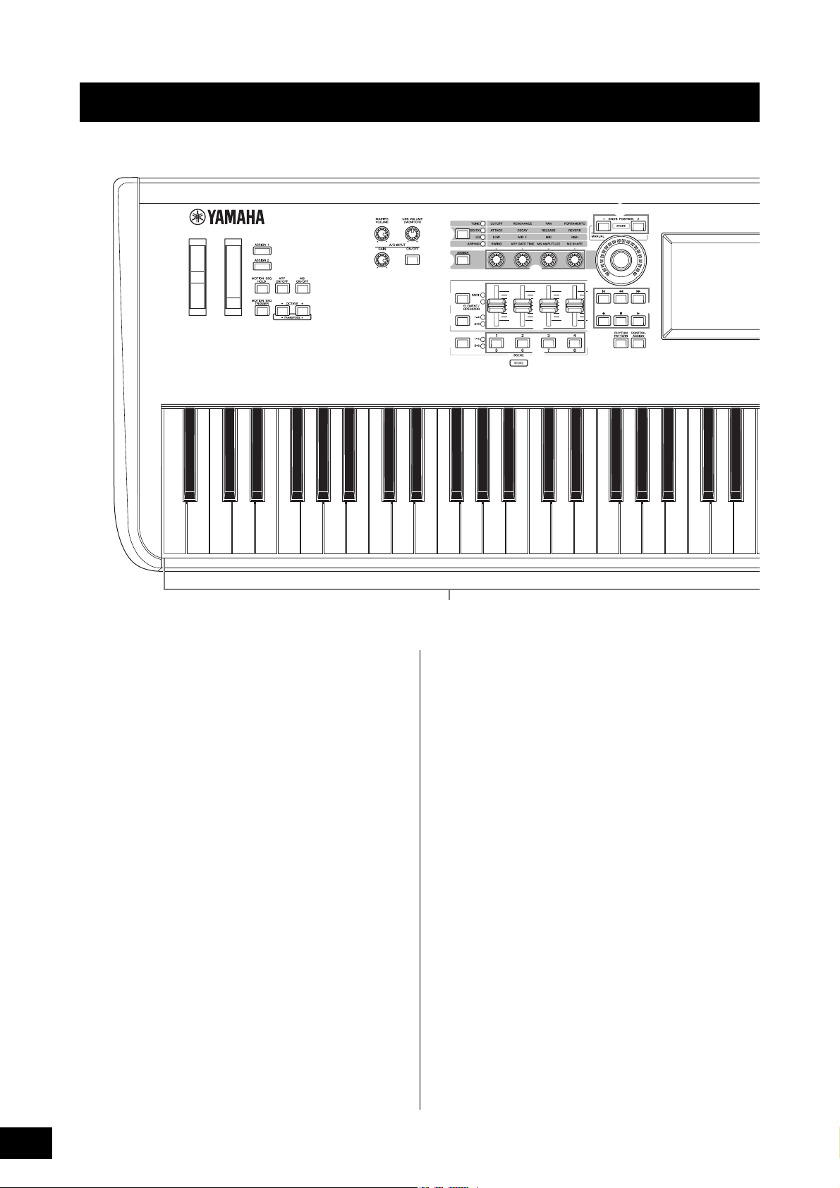
Top Panel
C1E0 F0 G0 A0 B0C0 D0A-1 B-1 C2
C3
1
23
4
7
6
H
G
C
B
%
8
9
)
D
^
!
(
#
$
A
I
F
@
*
&
5
E
Controls and Functions
1 Keyboard
The MODX6 features a 61-key keyboard, while the MODX7
has 76 keys and the MODX8 has 88 keys. With initial touch,
the instrument senses how strongly or softly you play the
keys, and uses that playing strength to alter the sound in
various ways, depending on the selected Performance.
2 Pitch Bend wheel
Controls the pitch bend effect. You can also assign other
functions to this controller.
3 Modulation wheel
Controls the modulation effect. You can also assign other
functions to this controller.
4 [MASTER VOLUME] knob (page 19)
Turn the knob clockwise or counterclockwise to control the
output level from the OUTPUT [L/MONO]/[R] jacks and the
[PHONES] jack.
5 [USB VOLUME (MONITOR)] knob
Controls the volume of the audio input from the [USB TO
HOST] jack to OUTPUT [L/MONO] and [R] jacks, and
[PHONES] jack.
6 A/D INPUT [GAIN] knob (page 50)
Use this to adjust the input gain of the audio signals at the
A/D INPUT [L/MONO]/[R] jacks. Turning the knob clockwise
increases the gain level.
NOTE
You may need to change the setting depending on the input level of
the external equipment connected to the A/D INPUT [L/MONO]/[R]
jacks, in the following order: [UTILITY] [Settings] [Audio I/O]
[A/D Input]. When the output level of the connected equipment (such
as a microphone, guitar or bass) is low, set this parameter to “Mic.”
When the output level of the connected equipment (such as a
synthesizer keyboard or CD player) is high, set this parameter to
“Line.”
7 A/D INPUT [ON/OFF] button (page 50)
Switches whether or not this instrument accepts the audio
signal input via the A/D INPUT [L/MONO]/[R] jacks. When A/
D Input is enabled, the button lights; when disabled, it turns
off.
8 [ASSIGN 1] and 9 [ASSIGN 2] buttons
(Assignable switches 1 and 2)
You can call up the specific Element/Operator of the
selected Performance by pressing each of these buttons
during your keyboard performance. In addition, you can
assign other functions to these switches. When one of these
effects is turned on, the corresponding button will light up
and vice-versa.
MODX Owner’s Manual
10
Page 15
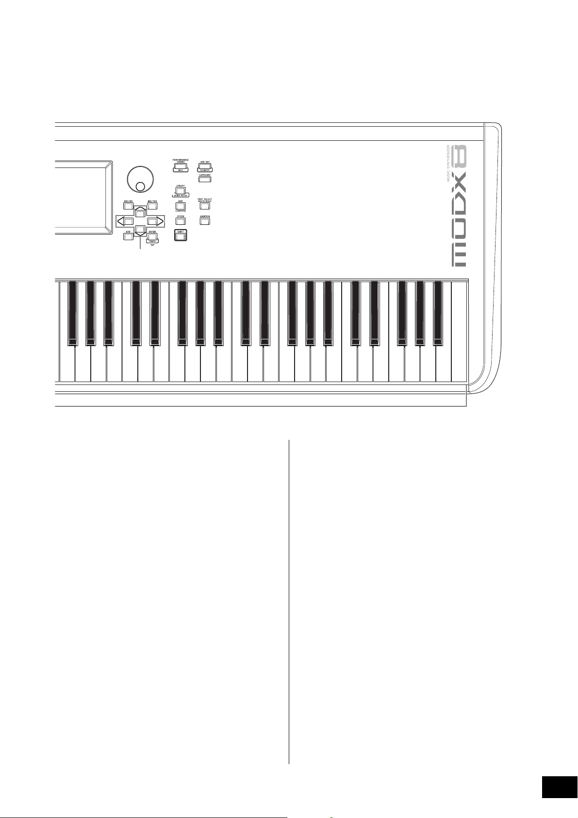
Controls and Functions
C4 C5 C6 C7
J
K
P
L
MNO
c
Q
R
S
T
a
d
b
The illustration shows the MODX8, but the information applies to all models.
) [MOTION SEQ HOLD] (Motion Sequencer
hold) button
Pressing this button while the Motion Sequencer is playing,
results in the sound being held or frozen at the exact point in
the sequence when the button was pressed. When the hold
effect is turned on, the button lights.
! [MOTION SEQ TRIGGER] (Motion Sequencer
trigger) button
When the Trigger Receive parameter of the Motion
Sequencer is set to ON, pressing this button starts Motion
Sequence playback. The button lights fully when pressed.
@ [ARP ON/OFF] (Arpeggio on/off) button
Press this button to enable or disable playback of the
Arpeggio. If the Arpeggio Switch of the selected Part is set to
off, however, pressing this button has no effect. When
Arpeggio is enabled, the button lights; when disabled, it
turns off.
# [MS ON/OFF] (Motion Sequencer on/off)
button
Determines whether the Motion Sequencer is active or not. If
the Motion Sequencer switch of the selected Part or Lane is
set to off, however, pressing this button has no effect. When
the Motion Sequencer is active, the button lights.
$ OCTAVE [-] and [+] buttons
Use these buttons to change the octave range of the
keyboard. These buttons also function as Transpose [-] and
[+] buttons. To lower or raise the pitch of the note in semitone
steps, hold down the [SHIFT] button and press the
corresponding [-]/[+] button. To restore the normal octave
setting, press both buttons simultaneously. The buttons light
or flash in different ways depending on the octave setting.
For details, see the Reference Manual PDF document.
MODX Owner’s Manual
11
Page 16
Controls and Functions
%
^
&
( Slider Select [1–4] [5–8] button
Selects four Control Sliders on the panel to use as 1–4 or 5–
8. Each time you press this button, the setting alternates
between 1–4 and 5–8. When the setting is 1–4 or 5–8, the
lamp for the selected setting lights up.
When you press the Slider Select button while holding down
the [SHIFT] button, you can set the Control Sliders to
function as 9–12 or 13–16. When the setting is 9–12 or 13–
16, the lamp for the selected setting flashes.
*
(
A
B
C
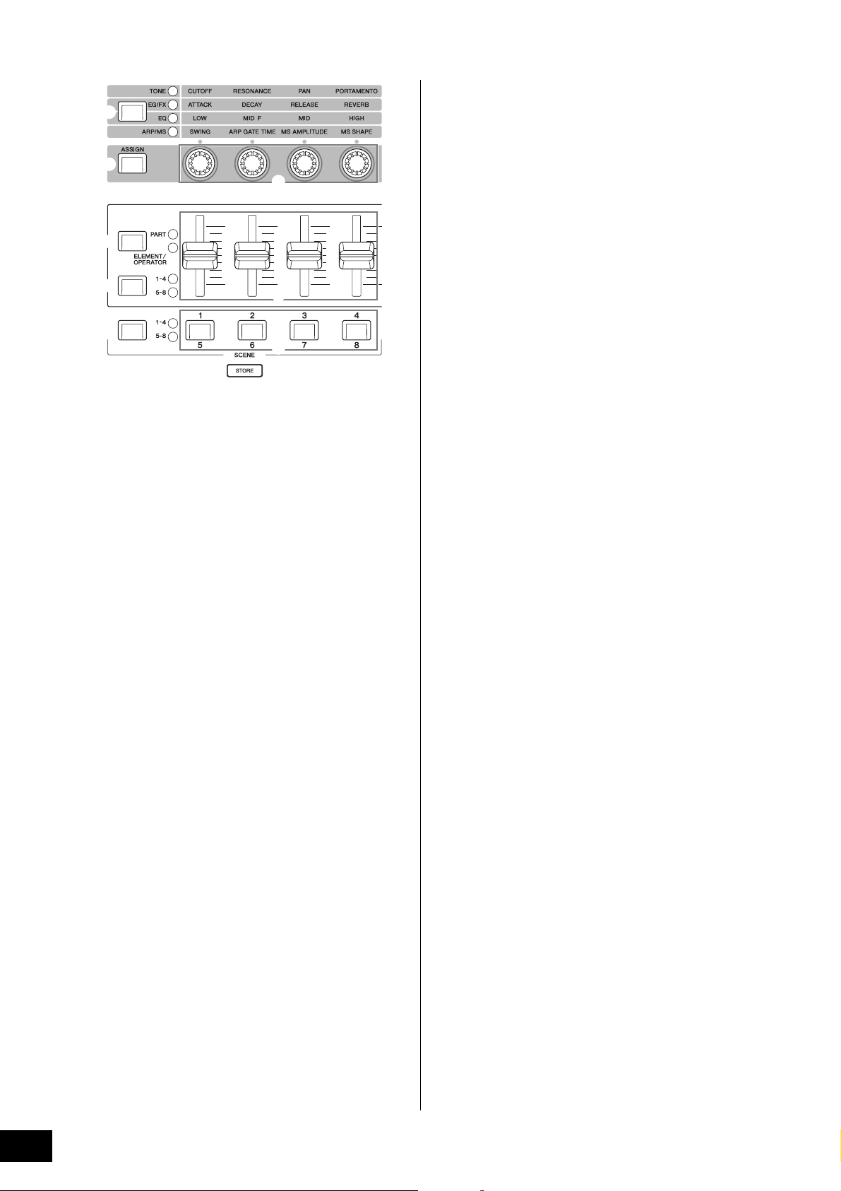
% Knob Function [TONE]/[EG/FX]/[EQ]/[ARP/
MS] button
Use this button to select functions to be assigned to Knobs.
The lamp next to the currently active parameters will light.
While the instrument is in the Performance Control status
(page 30), the function is applied commonly to all Parts,
while in the Part Control status (page 30), the function is
applied to the selected Part. The lamp for the selected
function will light.
^ [ASSIGN] button
Switches Knobs to function as Assign 1–4 or as Assign 5–8.
While the instrument is in the Performance Control status
(page 30), the function is applied commonly to all Parts,
while in the Part Control status (page 30), the function is
applied to the selected Part. The button lights when Assign
1–4 is selected, and the button flashes when Assign 5–8 is
selected.
& Knobs 1–4 (5–8)
These four highly versatile knobs on the panel let you adjust
various important parameters, such as the current Part,
Arpeggio tempo, and the Motion Sequencer.
Pressing the Knob Function [TONE]/[EG/FX]/[EQ]/[ARP/MS]
button on the upper left, or the [ASSIGN] button on the left
changes the functions assigned to these knobs. These
knobs function as Assignable Knobs when the [ASSIGN]
button is lit or flashing.
A Control Sliders 1–4 (5–8 / 9–12 / 13–16)
These sliders control the volume balance of the sound, by
letting you adjust the individual levels of the 16 Parts (1–4 /5–
8 / 9–12 / 13–16), the eight Elements for Normal Parts
(AWM2), the eight FM Operators for a Normal Part (FM-X),
and eight Keys of the Drum Part, in different ways depending
on the conditions of the various buttons.
NOTE
• If all of the Control Sliders are set to the minimum, you may not
hear any sound from the instrument, even when playing the
keyboard or a Song. If this is the case, raise all the sliders to a
suitable level.
• The [MASTER VOLUME] knob controls the overall audio output
level of this instrument. On the other hand, the Control Sliders
control the level of each Element/Key/Operator of the Parts and the
volume for each Part of the Performance as a parameter.
Accordingly, the values set via the Control Sliders can be stored as
Performance data.
B Scene Select [1–4] [5–8] button
Selects four SCENE buttons on the panel to use as Scenes
1–4 or Scenes 5–8. Each time you press this button, the
setting alternates between 1–4 and 5–8. The lamp for the
selected function lights up.
C SCENE [1/5] [2/6] [3/7] [4/8] buttons
You can assign different “snapshots” of important Partrelated parameters such as track mute status and the basic
Mixing setup to each of the SCENE buttons. You can switch
these buttons to function as Scenes 1–4 or as Scenes 5–8 by
pressing the Scene Select button.
When Scene-related parameters are edited and press any of
the SCENE [1/5]–[4/8] buttons while holding down the
[SHIFT] button, the edit is stored for the currently selected
[SCENE] button. The stored information is restored by
pressing the selected button. The currently selected button
fully lights, the button stored information lights dimly, and the
button without stored information is turned off.
* Slider Function [PART]/[ELEMENT/
Sets four Control Sliders on the panel to use for controlling
Parts or for controlling Elements. Each time you press this
button, the slider function alternates between PART and
ELEMENT/OPERATOR. The lamp for the selected function
lights up.
MODX Owner’s Manual
12
OPERATOR] button
Page 17

D KNOB POSITION [1] and [2] buttons
HG
D
F
E
Stores the parameter values of Assign 1–8. You can instantly
switch between the two buttons.
Pressing the KNOB POSITION [1] button while holding down
the [SHIFT] button, lets you store Value 1, and pressing the
KNOB POSITION [2] button while holding down the [SHIFT]
button, lets you store Value 2. Simultaneously pressing the
KNOB POSITION [1] and [2] switches the Super Knob
Motion Seq ON or OFF.
Controls and Functions
G [RHYTHM PATTERN] button
Use this button to call up the Rhythm Pattern display. You
select the Rhythm Pattern you want to use, and then press
[PERFORMANCE (HOME)] button or [EXIT] button to set the
selection.
Pressing this button again cancels the selection and closes
the Rhythm Pattern display.
H [CONTROL ASSIGN] button
While the parameter assignable to controllers is selected on
the display, press this button and operate the desired
controller for assignment. The controller setting display
appears.
I Touch panel LCD
The LCD indicates the parameters and values related to the
currently selected operation. You can operate by touching
the display.
E Super Knob
Simultaneously controls the parameters (Assign 1–8)
assigned to the Knobs.
NOTE
You can also control the Super Knob by using the foot controller
(FC7). For details, refer to page 33.
F SEQ TRANSPORT button
These buttons control recording and playback of the Song
sequence data.
[T] (Top) button
Instantly returns to the beginning of the current Song
(i.e., the first beat of the first measure).
[LL ] (Reverse) button
Press briefly to move back one measure at a time.
[RR ] (Forward) button
Press briefly to move forward one measure at a time.
[I] (Record) button
Press this to call up the Record setup display. (The
button flashes.) Press the [R] (Play) button to start
recording. (The [I] (Record) button lights.)
[J] (Stop) button
Press to stop recording or playback. This button can also
be used when you want to stop Arpeggio playback, even
when Arpeggio is set to continue playback even after the
note is released (Arpeggio hold switch is ON). You can
also use this button to stop a Motion Sequence that
receives Trigger signals.
[R] (Play) button
Press to start playback or recording of a Song. During
recording and playback, the button flashes at the current
tempo.
MODX Owner’s Manual
13
Page 18
Controls and Functions
J
KL
M
NO
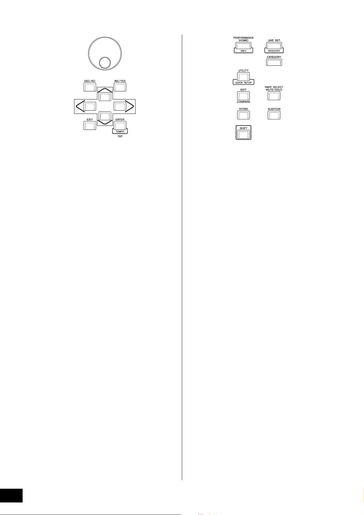
J Data dial
For editing the currently selected parameter. To increase the
value, turn the dial right (clockwise); to decrease the value,
turn the dial left (counter-clockwise). If a parameter with a
wide value range is selected, you can change the value in
broader strokes by quickly turning the dial.
K [DEC/NO] button
For decreasing the value of the currently selected parameter
(DEC: decrement). This button can also be used to cancel a
Job or Store operation.
Simultaneously hold down the [SHIFT] button and press the
[DEC/NO] button to quickly decrease the parameter value in
10-step jumps.
L [INC/YES] button
For increasing the value of the currently selected parameter
(INC: increment). This button can also be used to execute a
Job or Store operation.
Simultaneously hold down the [SHIFT] button and press the
[INC/YES] button to quickly increase the parameter value in
10-step jumps.
M Cursor buttons
The cursor buttons move the “cursor” around the display,
highlighting and selecting the various parameters.
N [EXIT] button
The menus and displays of the MODX are organized
according to a hierarchical structure. Press this button to exit
from the current display and return to the previous level in
the hierarchy.
O [ENTER] button
Use this button to call up the display of the selected menu,
or to execute a Job or Store operation.
Simultaneously hold down the [SHIFT] button and press the
[ENTER] button to call up the Tempo Settings display.
P
a
b
Q
R
S
c
d
T
P [PERFORMANCE (HOME)] button
Use this button to return to the Performance Play display.
The button fully lights when the Performance Play display is
shown. This button lights dimly when the Utility display is
shown.
When the Performance Play display is shown and the cursor
is on the Performance Name, pressing this button shows or
hides the detailed information, which is the same information
you can access by touching the [View] button on the Screen.
Simultaneously hold down the [SHIFT] button and press the
[PERFORMANCE (HOME)] button to call up the Overview
display.
Q [UTILITY] button
Use this button to call up the Utility display for making overall
system settings. The button fully lights when the Utility
display is shown and the button lights dimly when other
displays are shown.
Simultaneously hold down the [SHIFT] button and press the
[UTILITY] button to call up the Quick Setup display.
Pressing this button while holding down the [PART SELECT
MUTE/SOLO] button opens the Touch Panel Calibration
display.
R [EDIT] button
Use this button to call up the display for editing
Performances (page 22) and Live Sets (page 35). Also,
pressing this button while editing Performance parameters
lets you switch between the just-edited sound and its
original, unedited condition, allowing you to hear how your
edits affect the sound (Compare function). The button lights
when the edit display is shown and the button flashes while
Compare is active.
S [STORE] button
Use this button to call up the Store display. The button fully
lights when the Store display is shown and the button lights
dimly when other displays are shown.
MODX Owner’s Manual
14
T [SHIFT] button
Pressing this button along with another button enables you
to execute various commands. For details, refer to the “Shift
Function List” (page 62).
Page 19
Controls and Functions
a [LIVE SET] button
Use this button to store all your favorite, often-used
Performances in a single, easy-to-access location and call
them up.
Simultaneously hold down the [SHIFT] button and press the
[LIVE SET] button to call up the Live Set display for storing
the currently selected Performance to the Live Set. This is
one more useful way you can quickly switch among
Performances you need in live performance situations.
The button fully lights when the Live Set display is shown. If
the Live Set display is not shown, the button lights dimly
when the Live Set function is active and the button’s lamp is
off when the function is NOT active.
b [CATEGORY] button
The Category Search function (page 24) can be accessed
by using this button.
Use this button while the Performance Play display is shown
to call up the Performance Category Search display for
selecting the entire Performance. When the cursor is on the
Part name in the Performance Play display, simultaneously
hold down the [SHIFT] button and press the [CATEGORY]
button to call up the Part Category Search display, allowing
you to select a sound type for the currently selected Part.
The button fully lights when the Category Search display is
shown. If the Category Search display is not shown, the
button lights dimly when the Category Search function is
active and the button’s lamp is off when the function is NOT
active.
d [AUDITION] button
Use this button (in the Performance Play, Live Set, or
Category Search displays) to play back or stop a sample
phrase showcasing the selected Performance sound. This
sample phrase of the Performance is called the “Audition
phrase.” The button fully lights when it is ON and the button
lights dimly when the Audition function is active such as in
the Category Search display.
c [PART SELECT MUTE/SOLO] button
Use this button to select a Part or to turn Mute or Solo ON or
OFF. Pressing this button while in the Performance Play
display opens the Part Select window.
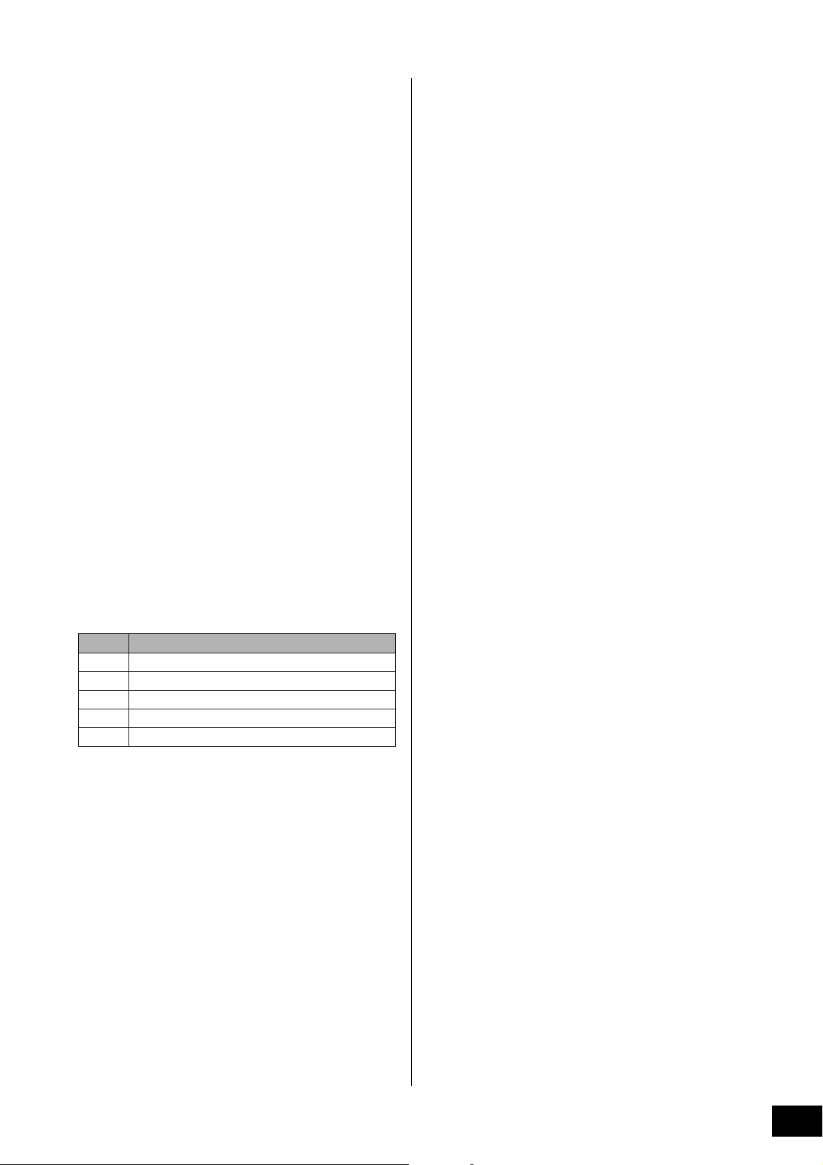
Button Operations
1–8 Shows Parts 1–8
9–16 Shows Parts 9–16
Select Switches to the Part Selection display
Mute Switches to the Mute Setting display
Solo Switches to the Solo Setting display
The letter “M” is shown for the Muted Part, and the letter “S”
is shown for the Soloed Part.
To close the Part Select window, press the button again or
touch the “x” mark on the Screen.
The button lights up fully while the Part Select window is
shown on the screen, and the button lights dimly when the
Part Select window is not shown. The button is turned off in
the Utility display or Live Set display, or any other displays
that do not require Part Select.
MODX Owner’s Manual
15
Page 20
Controls and Functions
Left side of Rear Panel
Right side of Rear Panel
Computer
USB flash drive
External MIDI keyboard
Powered
speakers
Headphones
Playback
equipment
Microphone
The illustration shows the MODX8, but the information applies to all models.
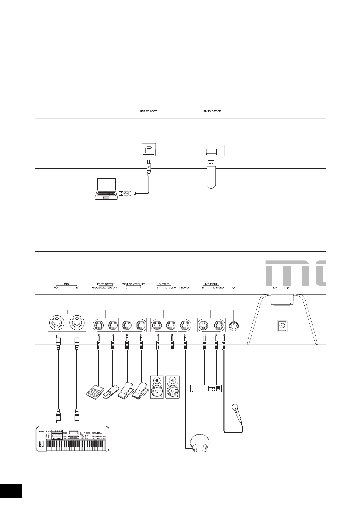
Rear Panel
12
3
4 5 6 87 9
FC4
FC5
FC3
FC4
FC5
FC7
)
MODX Owner’s Manual
16
Page 21

Controls and Functions
Left side of Rear Panel
1 [USB TO HOST] terminal
Used to connect this instrument to a computer via a USB
cable, and allows you to transfer MIDI data and audio data
between the devices. Unlike MIDI, USB can handle multiple
ports via a single cable (page 56). For information about
how the MODX handles Ports, see page 56.
NOTE
Audio data sending capability for this instrument is a maximum
10 channels (5 stereo channels). Audio data receiving capability is a
maximum 4 channels (2 stereo channels).
2 [USB TO DEVICE] terminal
Used to connect this instrument to a USB flash drive. This
lets you save data created on this instrument to a USB flash
drive and load data from a USB flash drive to the instrument.
Save/Load operations can be performed: [UTILITY]
[Contents] [Store/Save] or [Load].
NOTE
• Only USB flash drives can be recognized by this instrument. No
other USB devices (such as a hard disk drive, CD-ROM drive and
USB hub) can be used.
• The instrument supports the USB 1.1 to 3.0 standard. However,
note that the transfer speed differs depending on the data type
and the condition of this instrument.
Right side of Rear Panel
3 MIDI [IN], [OUT] terminals
MIDI [IN] is for receiving control or performance data from
another MIDI device, such as an external sequencer, letting
you control this instrument from the connected separate
MIDI device.
MIDI [OUT] is for transmitting all control, performance and
playback data from this instrument to another MIDI device,
such as an external sequencer. Also, MIDI [OUT] can be
used as MIDI Thru. To change the settings, press the
[UTILITY] button to open the Utility display.
4 FOOT SWITCH [ASSIGNABLE]/[SUSTAIN]
jacks
For connection of a separately sold FC3/FC4/FC5 Footswitch
to the [SUSTAIN] jack and a FC4/FC5 Footswitch to the
[ASSIGNABLE] jack. When connected to the [SUSTAIN]
jack, the Footswitch controls sustain. When connected to
[ASSIGNABLE], it can control one of various assignable
functions.
NOTE
• The term “FC3” in this Owner’s Manual refers collectively to the
FC3 and other footswitches compatible with the FC3, such as the
FC3A.
• The term “FC4” in this Owner’s Manual refers collectively to the
FC4 and other footswitches compatible with the FC4, such as the
FC4A.
5 FOOT CONTROLLER [1]/[2] jacks
For connection of a separately sold foot controller (FC7,
etc.). This jack lets you continuously control one of various
different assignable functions for Part edit—such as volume,
tone, pitch, or other aspects of the sound (see the Reference
Manual PDF document).
6 OUTPUT [L/MONO] and [R] jacks
Line level audio signals are output via these standard phone
jacks. For monophonic output, use only the [L/MONO] jack.
7 [PHONES] (Headphone) jack
This standard stereo phones jack is for connection to a set of
stereo headphones. This jack outputs audio signals identical
to those from the OUTPUT [L/MONO] and [R] jacks.
8 A/D INPUT [L/MONO]/[R] jacks
External audio signals can be input via these phone jacks
(1/4" mono phone plug). Various devices such as a
microphone, CD player or synthesizer can be connected to
these jacks and their audio input signal can be sounded as
the Audio Part.
In addition, you can use the special Vocoder feature by
connecting a microphone to this [L/MONO] jack and
inputting your voice to the microphone.
You can also use the Envelope Follower and ABS (Audio
Beat Sync) features. Envelope Follower is a function for
detecting the volume envelope of the input signal waveform
and modifying sounds dynamically.
NOTE
• A guitar or bass having active pickups can be directly connected.
However, when using passive pickups, connect the instrument via
an effect device.
• The Vocoder/Envelope Follower can be controlled from all Part
outputs, and not just the A/D INPUT [L/MONO]/[R] jacks.
ABS (Audio Beat Sync) is a function for detecting the beat of
the audio signal input from these jacks and synchronizing
the beat with the Motion Sequencer or Arpeggio.
Use 1/4" mono phone plugs. For stereo signals (such as from
audio equipment), use the [L/MONO]/[R] jacks. For mono
signals (such as from a microphone or guitar), use only the
[L/MONO] jack.
For details about the Envelope Follower and ABS features,
see the Reference Manual PDF document.
9 [P] (Standby/On) switch
Press to set the power to On or Standby.
) [DC IN]
Plug the AC adaptor supplied with this instrument.
MODX Owner’s Manual
17
Page 22
WARNING
CAUTION
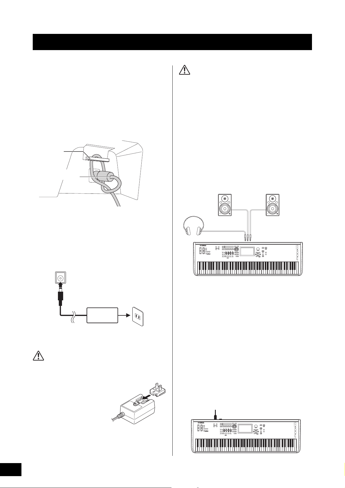
Setting Up
Cable clip
Be careful not to bend
the connector
DC IN jack (page 16)
AC outlet
AC adaptor
Plug
Slide the plug as indicated.
The shape of the plug differs
depending on your area.
Powered speaker (left)
Powered speaker (right)
Headphones
OUTPUT L/MONO OUTPUT R
PHONES
DC IN
[P] (Standby/On) switch
Power Supply
Connect the supplied AC adaptor in the following order.
Before you connect the AC adaptor, make sure the
[P] (Standby/On) switch on the instrument is set to the
Standby
1 Wrap the DC output cable of the AC adaptor
(N) position.
around the cable clip (as shown below), and
then connect the plug of the adaptor to the
DC IN jack on the rear panel.
• When setting up the product, make sure that the AC outlet you
are using is easily accessible. If some trouble or malfunction
occurs, immediately turn the power off and disconnect the
plug from the outlet.
• The instrument remains charged and draws a small amount of
power even when the [P] (Standby/On) is set to the Standby
position. For this reason, if you intend not to use it for an
extended period of time, make sure to unplug the power cord
from the wall outlet.
Connecting Speakers or Headphones
Since the instrument has no built-in speakers, you will need
to monitor the sound of the instrument by using external
equipment. Connect a set of headphones, powered
speakers, or other playback equipment as illustrated below.
When making connections, be sure that your cables have
the appropriate ratings.
NOTE
Use of the cable clip prevents accidental unplugging of the
cable during operation. Make sure to avoid tightening the cord
more than necessary or pulling on the cord strongly while it is
wrapped around the cable clip to prevent wear on the cord or
possible breakage of the clip.
2 Connect the other end of the AC adaptor to
an AC outlet.
NOTE
Reverse the order of the instruction steps above when disconnecting
the AC adaptor.
• Use the specified AC adaptor (page 71) only. Using the wrong
AC adaptor can result in damage to the instrument or
overheating.
• When using the AC adaptor with
a removable plug, make sure to
18
keep the plug attached to the AC
adaptor. Using the plug alone can
cause electric shock or fire.
• Never touch the metallic section
when attaching the plug. To avoid
electric shock, short circuit or
damage, also be careful that
there is no dust between the AC
adaptor and plug.
MODX Owner’s Manual
1
Powering Up the System
Make sure the volume settings of the instrument and external
2
devices such as powered speakers are turned to the
minimum before turning the power on. When connecting the
instrument to powered speakers, turn on the power switch of
each device in the following order.
When turning the power on:
First, the instrument (the display will turn on and the buttons
will light), then the connected powered speakers.
When turning the power off:
First, the connected powered speakers, then the instrument
(the display will turn off and the buttons will turn off).
Keep in mind that the [P] (Standby/On) switch is located at
the left side (from the view of the keyboard) of the DC IN
socket on the rear panel of the instrument.
Page 23
Setting Up
CAUTION
Max.
Min.
Auto Power Off function
To prevent unnecessary power consumption, this instrument
features an Auto Power Off function that automatically turns
the power off if the instrument is not operated for a specified
period of time.
Auto Power Off Setting
The amount of time that elapses before the power is
automatically turned off can be set.
Instructions:
Setting Value (min.):
Default Setting (min.):
Disabling Auto Power Off (simple method)
Turn the power on while holding down the lowest key on the
keyboard. An “Auto power off disabled” message appears
briefly and Auto Power Off is disabled. The setting is retained
even if the power is turned off.
[UTILITY] [Settings] [System] [Auto
Power Off]
off (disables Auto Power Off), 5, 10, 15, 30,
60, 120
off
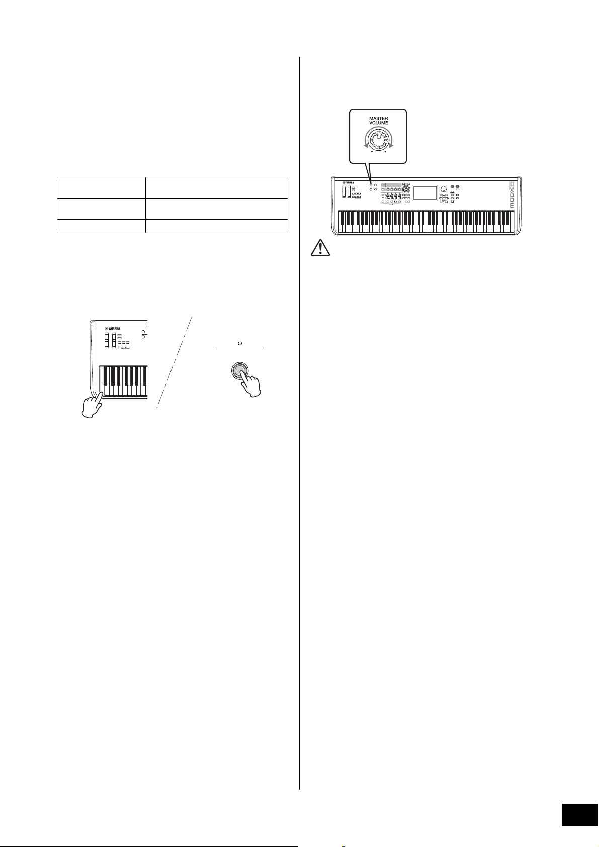
Adjusting the Master Volume output
Adjust the overall level of this instrument by using the
[MASTER VOLUME] knob.
Do not listen with the headphones at high volume for long
periods of time. Doing so may cause hearing loss.
Restoring the initial factory settings (Initialize All Data)
NOTICE
When the Initialize All Data operation is executed, all the
Performance, Song, and any system settings you created on the
Utility display will be erased. Make sure you are not overwriting
any important data. Be sure to save all important data to your
USB flash drive before executing this procedure (page 60).
NOTICE
• Even when the power is turned off, electricity is still flowing to
the instrument at the minimum level. To shut off the electricity
completely, make sure you unplug the power cord from the
wall AC outlet.
• Depending on the instrument status, the power may not turn
off automatically, even after the elapse of the specified period
of time. Always turn off the power manually when the
instrument is not in use.
• When the instrument is not operated for a specified period of
time while connected to an external device such as an
amplifier, speaker or computer, make sure to follow the
instructions in the Owner’s Manual to turn off the power to the
instrument and the connected devices in the proper sequence,
in order to protect the devices from damage. If you do not
want the power to turn off automatically when a device is
connected, disable Auto Power Off.
• The setting will revert to its default value if not backed up
before the power is turned off.
• When Auto Power Off is set to “off,” the value will be retained
even if the backup data saved on another device is loaded to
the instrument. When Auto Power Off is set to something other
than “off,” the value will be overwritten with loaded data.
NOTE
• The setting time is approximate.
• To turn the power on after Auto Power Off has been executed,
press the [P] (Standby/On) switch to set the switch to the
Standby (N) position and press it again to turn ON.
• When the factory settings are restored, the setting is changed to
the default value (off).
1 Press the [UTILITY] button or touch the
UTILITY icon in the upper right of the screen
to call up the Utility display.
2 Touch the [Settings] tab in the left of the
screen and then touch the [System] tab.
The entire system setting display appears.
3 Touch [Initialize All Data] in the lower right of
the screen.
The display prompts you for confirmation. To cancel this
operation, touch the [Cancel No] in the screen or press
the [DEC/NO] button on the panel.
4 Touch [Yes] in the screen or press the [INC/
YES] button to execute the Initialize All Data
operation.
MODX Owner’s Manual
19
Page 24
Basic Operation and Displays
1 2 76543
Navigation bar
8)
The MODX features a convenient touch panel display. You can operate various settings and select desired parameters by
directly touching the screen. Furthermore, you can use the data dial and other buttons for display operations.
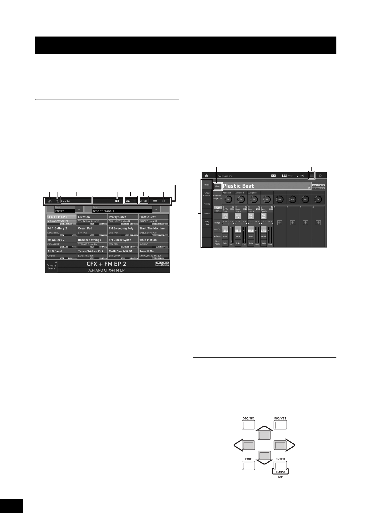
Display (touch panel) configuration
This section explains the navigation bar and the display
selecting tabs which are common to all types of displays. For
the purpose of illustration, the Live Set display which MODX
appears when the MODX is turned on and the Performance
Play display (Home) are used as examples.
NOTE
You can change the start-up display (the display that first appears
when the power is turned on). For details about the setting, see
page 51.
Live Set display
6 TEMPO SETTINGS icon
Displays the tempo of the currently selected
Performance. Touch the icon to call up the Tempo
settings display.
7 UTILITY icon
Touch the icon to call up the last opened display among
the Utility displays.
Performance Play display
9
8 LIVE SET icon
Touch the icon to call up the Live Set display.
1 HOME icon
Moves to the Performance Play display.
2 EXIT icon
Functions same as the [EXIT] button on the panel. Press
this icon to exit from the current display and return to the
previous level in the hierarchy.
3 INFORMATION area
Displays helpful information, including the currently
selected display name.
4 EFFECT icon
Touch the icon to call up the Effect switch display. The
icon turns off when any of the Effect blocks (Insertion,
System or Master) is off.
5 QUICK SETUP icon
Displays the settings of Local Control ON/OFF and MIDI
IN/OUT.
The keyboard-shaped icon lights up when Local Control
is set to ON and turns off when Local Control is set to
OFF.
When MIDI is set as the MIDI IN/OUT setting, a MIDI
connector-shaped icon appears. When USB is set as the
MIDI IN/OUT setting, a USB connector-shaped icon
appears.
Touch the desired icon to call up the corresponding
quick setup display.
9 Display selecting tabs
Touch the desired tab to call up the corresponding
display.
) View button
Determines whether the detailed information of each Part
is displayed (On) or not displayed (Off). The displayed
information differs depending on the cursor position or
the Slider function settings.
Moving the cursor
Use these four buttons to navigate the display, moving the
cursor around the various selectable items and parameters
in the screen. When selected, the relevant item is highlighted
(the cursor appears as a dark block with inverse characters).
You can change the value of the item (parameter) at which
the cursor is located by using the data dial, [INC/YES] and
[DEC/NO] buttons.
MODX Owner’s Manual
20
Page 25
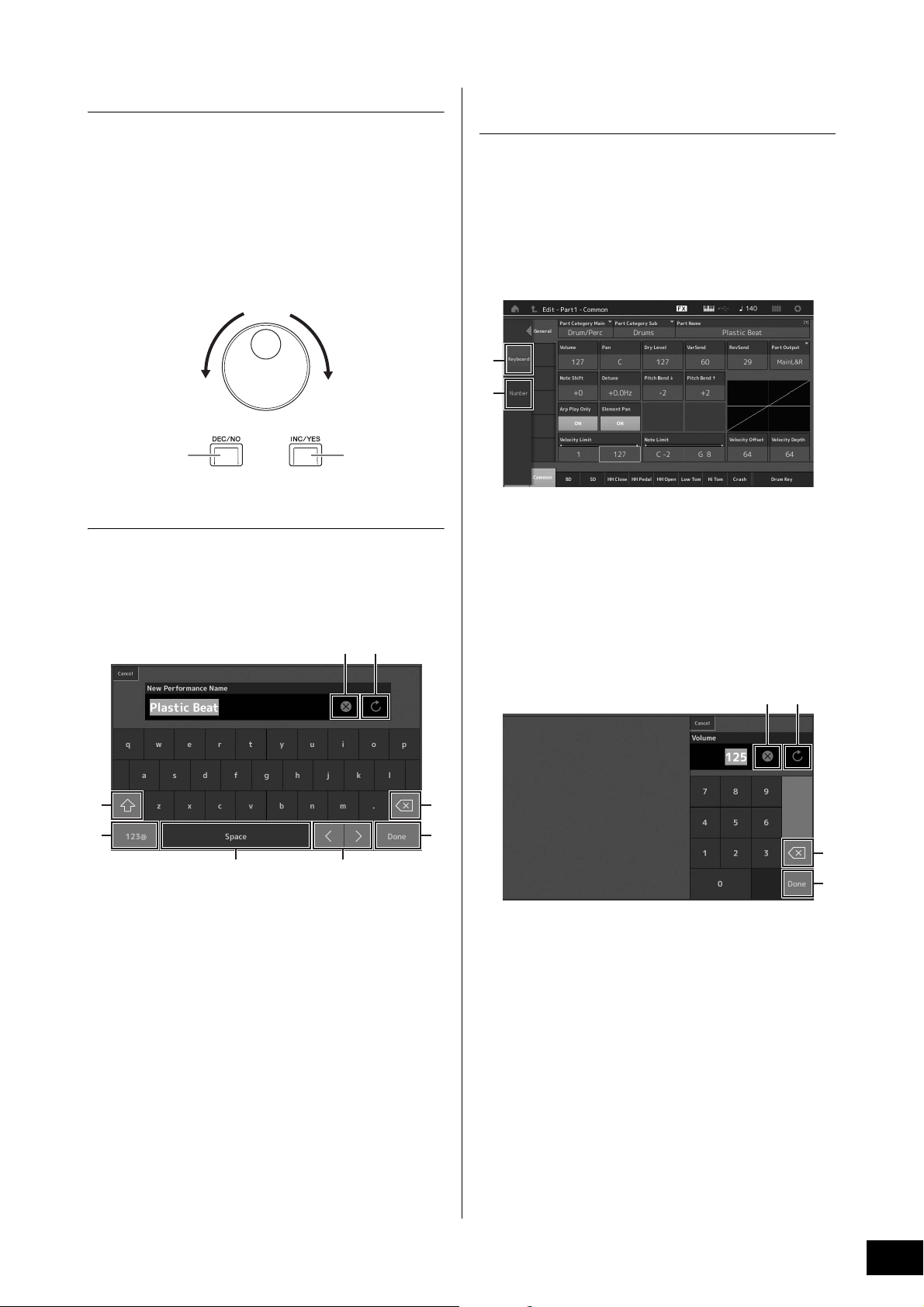
Changing (editing) parameter values
Increases numberDecreases number
Increases number
Decreases number
3
4
21
5 6
7
8
1
2
43
Rotating the Data dial to the right (clockwise) increases the
value, while rotating it to the left (counter-clockwise)
decreases it.
Pressing the [INC/YES] button increases a parameter value
by one step, and pressing [DEC/NO] button decreases it.
For parameters with large value ranges, you can increase
the value by 10 by simultaneously holding down the [SHIFT]
button and pressing the [INC/YES] button. To decrease by
10, simultaneously hold down the [SHIFT] button and press
the [DEC/NO] button.
Inputting using the keys on the
keyboard and numeric keypad display
For some parameters, you can also enter the value directly,
using the LCD as a numeric keypad or using keys on the
keyboard. Input via the keys is activated for the parameters
where the numerical values should be entered. Input via the
numeric keypad display is activated when inputting values.
Touch the desired parameter or move the cursor to the
parameter and press the [ENTER] button to call up the
display having the two menus (shown below).
Naming (inputting characters)
You can freely name the data you’ve created, such as
Performances, Songs, and files saved to a USB storage
device. Touch the Naming parameter or move the cursor to
the Naming parameter and press the [ENTER] button to call
up the input character display.
1 Deletes all characters.
2 Reverts to the default name.
3 Switches between uppercase and lowercase
alphabetical characters.
4 Calls up the display for entering numbers, punctuation
marks and miscellaneous characters.
5 Inserts a space (blank) at the cursor position. (You can
also use the [INC/YES] button for the same operation.)
6 Moves the cursor position.
7 Deletes the previous character (backspace). (You can
also use the [DEC/NO] button for the same operation.)
8 Completes the text input and closes the display.
1 Enables keyboard input.
You can play any note on the keyboard and the note or
velocity are input.
2 Enables numeric keypad input.
You can input a number directly by using the numeric
keypad. You can also use the data dial, the [INC/YES]
button, and the [DEC/NO] button to increase and
decrease the input number.
Numeric keypad display
5
6
3 Erases all numbers.
4 Restores the value to the last setting.
5 Deletes the last digit of the number.
6 Completes the input operation and closes the numeric
keypad display.
MODX Owner’s Manual
21
Page 26
Selecting Performances
Multiple
Performances
One Performance
Part 1 (Piano)
Part 2 (Guitar)
Part 3 (Bass)
Par t 4 (D rum)
Part 16
The MODX has 16 Parts and basic musical instrument
sounds are assigned to each Part. A single set of these
sounds is called a “Performance.” You can change sounds
as desired by selecting the appropriate Performance.
There are three Part types as follows.
Normal Parts (AWM2)
Normal Parts (AWM2) are mainly pitched musical instrument
type sounds (piano, organ, guitar, synthesizer, etc.) that can
be played over the full range of the keyboard.
Normal Parts (FM-X)
Normal Parts (FM-X) are powerful FM Synthesis system
sounds. This sound is played conventionally from the
keyboard, with standard pitches sounding for each key.
Drum Parts
Drum Parts are mainly percussion/drum sounds that are
assigned to individual notes.
This instrument features Banks for memorizing
Performances. There are basically four different types of
Banks: Preset, User, Library, and GM. The contained
Performances and features depend on the Bank as
described below.
Preset Banks
The Preset Banks contain a full set of specially programmed
Performances. Performances you’ve edited yourself cannot
be saved in the Preset Banks.
User Banks
The User Banks contain the Performances you have edited
and stored. The User Banks are initially empty.
NOTICE
If a Performance in a User Bank (User Performance) is
overwritten or replaced, that User Performance will be lost. When
you store an edited Performance, be careful not to overwrite any
important User Performances.
Library Banks
The Library Banks contain the Performances you have
added as Libraries. The Library Banks are initially empty.
(A Library can be added by importing a library file.)
GM Bank
The GM Bank contains the Parts allocated according to the
GM standard.
GM
GM (General MIDI) is a worldwide standard for Voice
organization and MIDI functions of synthesizers and tone
generators. It was designed primarily to ensure that any
song data created with a specific GM device would sound
virtually the same on any other GM device—no matter the
manufacturer or the model. The GM bank on this
synthesizer is designed to appropriately play back GM
song data. However, keep in mind that the sound may not
be exactly the same as played by the original tone
generator.
22
Performances can also be divided into two groups as
follows.
Single Part Performances
A Single Part Performance contains only one Part. Select this
if you want to play a single instrument.
Multi Part Performances
A Multi Part Performance contains multiple Parts. Select this
if you want to play sounds of multiple instruments by using
layering and splitting functions.
MODX Owner’s Manual
Each of these Banks include Performances organized
according to the Performance type.
NOTE
• For details about Performances, refer to “Basic Structure” in the
Reference Manual PDF document.
• For lists of the Performances, refer to the separate Data List PDF.
Page 27
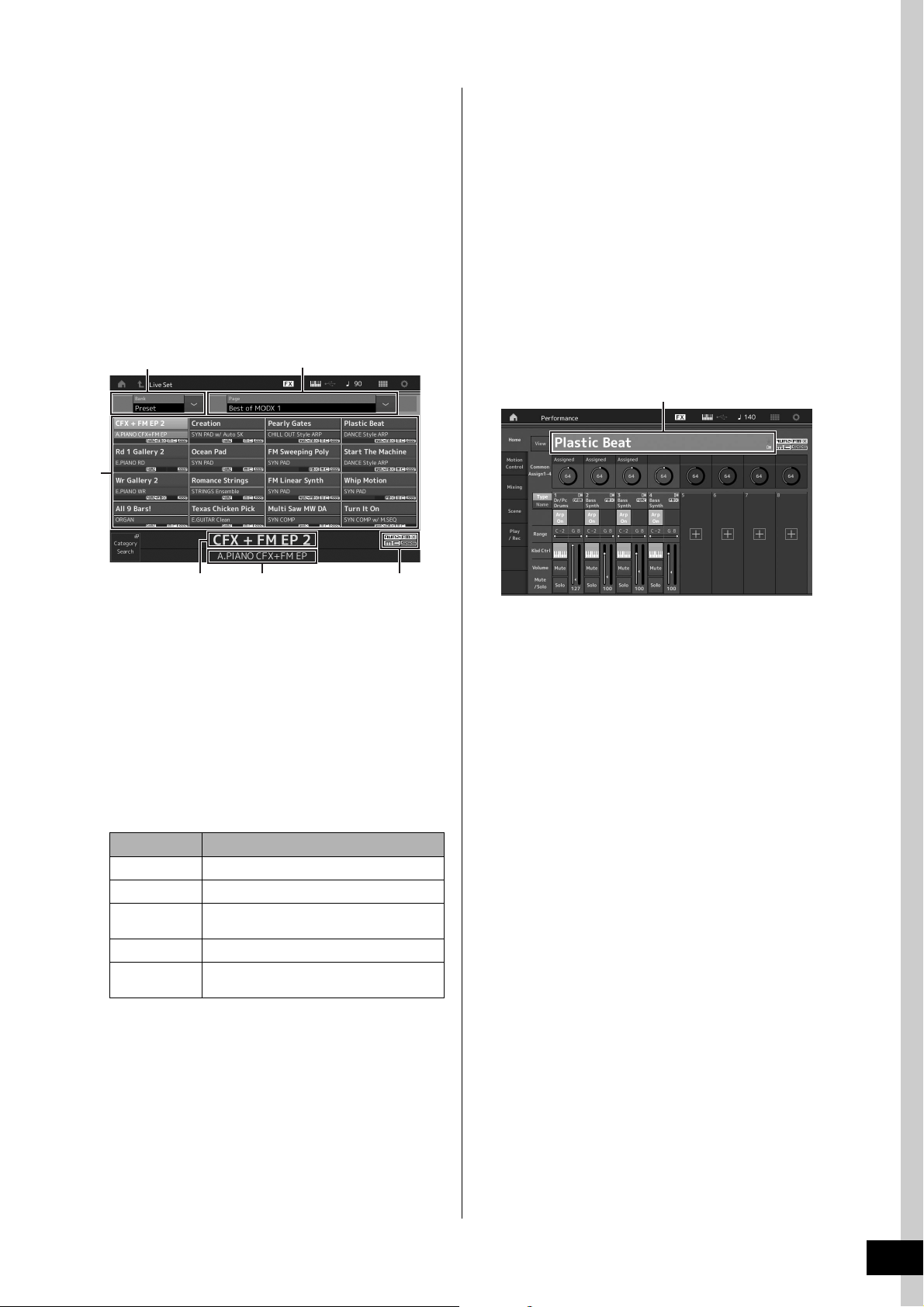
Selecting Performances
1
Performance name
When you turn on your instrument for the first time, a Live Set
of the Preset Banks will be displayed in the top display. The
Live Set is a list in which Performances can be freely
arranged. Up to 16 Performances can be arranged over a
single page. You can play various Performances selected
from the Preset Live Sets.
Selecting a Performance from the Live Set
1 Press the [LIVE SET] button.
This calls up the Live Set display.
2
3
2 Touch the desired Performance on the
screen.
NOTE
To rearrange the order of the Performances registered in the Live
Set, see page 35.
3 Play the keyboard.
Switching Performances
1 Press the [PERFORMANCE (HOME)] button.
The Performance Play display appears, and the current
Performance name is shown.
4
5 6
1 Page (switched by pressing [u] [d] in the screen)
NOTE
You can also use [SHIFT] and [INC/DEC] or [SHIFT] and [DEC/
NO] for switching pages.
2 Preset Bank/User Bank (switched by pressing the
[u] [d] in the screen)
3 Performance list
4 Active Performance names
5 Slot name
6 Flag (see chart below)
Flag Definition
AWM2 Performance comprised only of AWM2 Parts
FM-X Performance comprised only of FM-X Parts
AWM2+FM-X Performance comprised of both AWM2 and FM-
MC Performance featuring Motion Control
SSS Performance featuring Seamless Sound
NOTE
“Seamless Sound Switching” is a feature that lets you switch
Performances smoothly without any notes being cut off. The SSS
feature is available for all Preset Bank Performances in this
instrument. However, SSS is available only for the Performance
containing Parts 1–4, not for the Performance with using Parts 5–
16.
X Parts
Switching
2 Move the cursor to the Performance name
and select the desired Performance by using
the data dial, the [INC/YES] button, or the
[DEC/NO] button.
NOTE
• To quickly move forward through the Performance numbers in
10-step jumps, simultaneously hold down the [SHIFT] button
and press the [INC/YES] button.
• To decrease by 10, do the opposite; simultaneously hold
down the [SHIFT] button and press the [DEC/NO] button.
3 Play the keyboard.
MODX Owner’s Manual
23
Page 28

Selecting Performances
6
4
5
1 2 3
7 89
Using the Category Search function
The Performances are conveniently divided into specific
Categories, irrespective of their bank locations. The
categories are divided based on the general instrument type
or sound characteristics. The Category Search function
gives you quick access to the sounds you want.
1 Press the [CATEGORY] button while the
Performance Play display is shown.
This calls up the Category Search display.
NOTE
You can open the Category Search display by selecting
[Category Search] from the menu that is called up when the
Performance name is touched.
1 Bank
2 Attribute
NOTE
Attributes are Performance properties and sorted according
to tone generator types or parts of Performances.
3 Keyword search
4 Main categories
5 Sub categories
6 Performance list of the selected category
NOTE
The selected Performance is displayed in white,
Performances with a single part are in green, and
Performances with multi parts are in blue.
7 For changing the sorting order
8 For changing the Performance list page
9 Adding to or deleting from the Favorite List
3 Touch and select the desired sub category
(
5).
This calls up the Performance lists of the selected
category (6).
4 Touch the desired Performance.
5 Touch the HOME icon or EXIT icon to actually
call up the selected Performance.
This closes the Category Search display.
NOTE
You can also use the [ENTER] button, the [EXIT] button, or the
[PERFORMANCE (HOME)] button to finalize the selection.
Below is a list of the Categories and their panel
abbreviations.
Abbreviation Category
Piano Piano
Keyboard Keyboard instruments (Harpsichord, Clav,
Organ Organ
Guitar Guitar
Bass Bass
Strings Strings
Brass Brass
Woodwind Woodwind instruments
Syn Lead Synth Lead
Pad/Choir Synth Pad
Syn Comp Synth Comp
Chromatic Perc Chromatic Percussion (Marimba,
Drum/Perc Drum/Percussion
Sound FX Sound Effect
Musical FX Musical Effect
Ethnic Ethnic
No Assign No Assign
Init Initialize
etc.)
Glockenspiel, etc.)
6 Play the keyboard.
2 Touch and select the desired main category
MODX Owner’s Manual
24
(
4).
NOTE
• You can filter the Performance lists by touching [Bank] (1)
and selecting the desired bank type from the list.
• You can also filter the Performance lists by touching [Attribute]
(2) and selecting the desired attribute type from the list.
• You can also call up your own favorite Performances instantly.
To enable this, touch [Set] (9) on the screen and bookmark
your favorite Performances beforehand.
Page 29

Selecting Performances
[Audition]
Selecting an Initialized Performance
Follow the steps below to select an Initialized
Performance.
1 Touch [Init] of the main category in the
Category Search display.
2 Only initialized Performances are
displayed in the Performance list.
The Initialized Performances are divided into three
categories: [Init Normal (AWM2)] for the normal
Parts (AWM2), [Init Normal (FM-X)] for the normal
Parts (FM-X), and [Init Drum] for the Drum Parts.
3 Select the desired Performance.
Selecting only Single Part Performances
You can filter out the Single Part Performances by using
the Attribute function.
Playback Audition phrase
You can hear a sample of Performance sounds. The sample
sound is referred to as “Audition phrase.”
1 Touch [Audition] in the Category Search
display.
The sample of the currently selected Performance plays.
If you select a different Performance during Audition
phrase playback, the audition phrase switches to that of
the newly selected Performance.
2 Touch [Audition] again to stop playback.
NOTE
• You can also playback/stop the Audition phrase by pressing
the [AUDITION] button on the front panel.
• You can playback/stop the Audition phrase by pressing the
[AUDITION] button on the front panel while the Performance
display or the Live Set display is shown.
1 Touch [Attribute] in the Category Search
display.
2 Touch [Single] from the menu in the left
of the screen.
3 Only Single Part Performances are
displayed in the Performance list, letting
you select the desired one.
MODX Owner’s Manual
25
Page 30
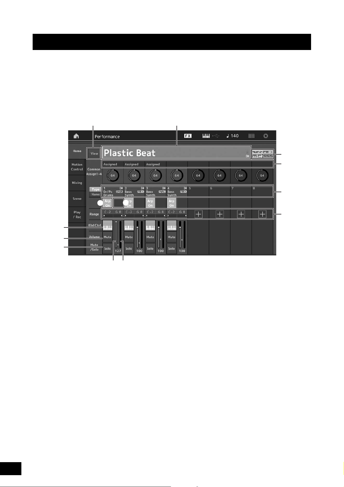
Playing the Keyboard
1#
3
2
4
7
You can mix several different parts together in a layer, or split them across the keyboard, or even set up a combination layer/
split. Each Performance can contain up to eight different Parts. Press the [PERFORMANCE (HOME)] button before playing the
keyboard.
Performance Play display
In this condition, playing the keyboard sounds the Performance indicated in the display. The parameters shown in the
Performance Play display are briefly explained below. You can operate the icons by touching on the display.
6
8
9
)
1 Performance name
2 Flag
3 Functions assigned to knobs
4 Part names
5 Switching Motion Sequencer on/off for Parts
6 Switching Arpeggio on/off for Parts
7 Note Limit for Parts
8 Switching Keyboard Control on/off for Parts
9 Switching Mute on/off for Parts
) Switching Solo on/off for Parts
! Volume of Parts 1–8
@ Meter (Audio Output Level)
# Showing or hiding detailed information on each Part
5
!@
MODX Owner’s Manual
26
Page 31
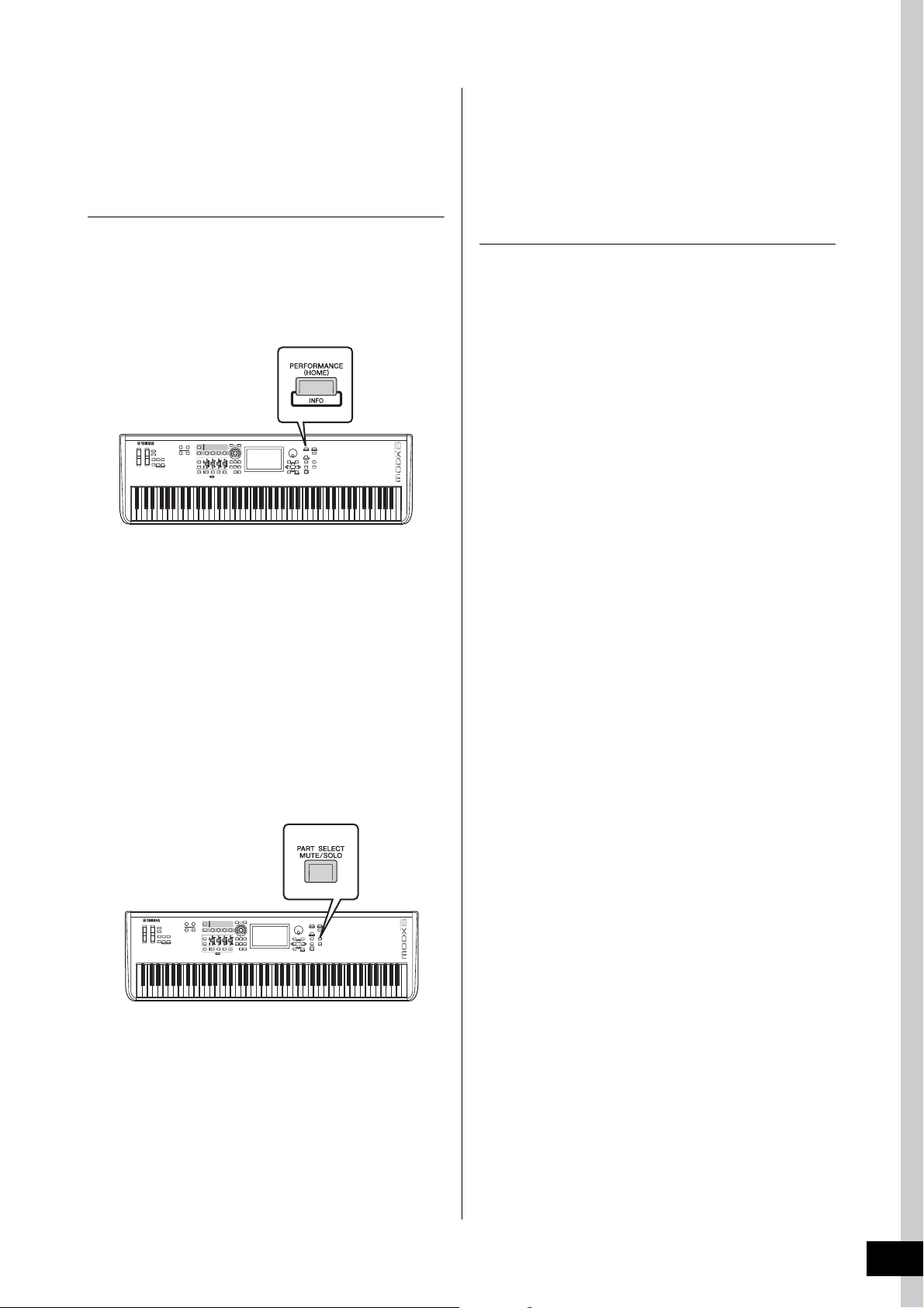
Playing the Keyboard
Switching a Part on/off
You can turn the eight Parts of the current Performance on or
off as desired.
Turning specific Parts on/off (Mute
function)
You can turn individual Parts on/off by using the Mute
function.
1 Press the [PERFORMANCE (HOME)] button.
The button lamp lights, indicating that each Part can be
turned on/off.
2 Touch the [MUTE] button on the screen to
mute the Part.
Touch the same button again to turn the button off and
disengage the mute function for that Part. You can turn
multiple Parts on/off by touching their buttons.
4 To disengage the mute function, with “MUTE”
selected, touch the button with the letter “M”
shown on it.
The “M” indication disappears and the Mute function is
disengaged.
Soloing a specific Part (Solo function)
The Solo function is the opposite of Mute, and lets you
instantly solo a specific Part and mute all others.
1 Press the [PERFORMANCE (HOME)] button.
2 Touch the [SOLO] button on the screen to
solo the Part.
The [SOLO] button lights, indicating that Solo is enabled.
Touch the same button again turns the off the button to
disengages the solo function.
You can also solo a part by using the [PART SELECT MUTE/
SOLO] button with the operation below.
1 While the Performance display is shown,
press the [PART SELECT MUTE/SOLO]
button.
The Part Select Windows appears on the display.
2 Touch the number button for the Part you
wish to solo.
You can also mute parts by using the [PART SELECT MUTE/
SOLO] button with the operation below.
1 While the Performance display is shown,
press the [PART SELECT MUTE/SOLO]
button.
The Part Select Windows appears on the display.
2 Touch the [MUTE] button on the Part Select
Window to turn the button on.
3 Touch the number button for the Part you
wish to mute. The letter “M” appears on the
button, and the corresponding Part will be
muted.
You can turn multiple Parts on/off by pressing multiple
buttons.
3 Touch the [SOLO] button on the Part Select
Window to turn the button on.
The letter “S” appears on the currently selected Part, and
the corresponding Part will be soloed.
4 To disengage the solo function, with “SOLO”
selected, touch the button with the letter “S”
shown on it.
The “S” indication disappears and the Solo function is
disengaged.
MODX Owner’s Manual
27
Page 32

Playing the Keyboard
Using the Arpeggio function
This function lets you trigger rhythm patterns, riffs and
phrases using the current Part by simply playing notes on
the keyboard.
It not only provides inspiration and full rhythmic passages in
your live performances, but it gives you fully formed
instrumental backing parts of various music genres for ease
in creating songs.
You can assign the desired eight Arpeggio Types to each
Part and play back the Arpeggios of up to eight Parts
simultaneously.
You can also set the Arpeggio playback method, Note
range, Velocity range and Play Effects to create your own
original grooves.
NOTE
For details about Arpeggio, see the Reference Manual PDF
document.
Turning the Arpeggio on/off
To turn Arpeggio playback on or off, press the [ARP ON/
OFF] button on the panel.
Using the Motion Sequencer function
The powerful Motion Sequencer feature lets you dynamically
change sounds by operating Parameters depending on
sequences created in advance.
It provides real time control for changing sounds depending
on various sequences such as Tempo, Arpeggio, or the
rhythm of external connected devices.
You can assign up to eight desired Sequence types for one
Lane.
You can also set up to four Lanes corresponding to the
Motion Sequencer function for one Part. Up to eight Lanes
can be used at the same time for the entire Performance.
For the Motion Sequencer function, in addition to being able
to set the Arpeggio playback method, you can also set the
Velocity range, Play Effects, the amount of steps, and so on,
to create your own original grooves.
NOTE
For details about the Motion Sequencer, see the Reference Manual
PDF document.
Turning Motion Sequencer on/off
Press the [MS ON/OFF] button on the front panel to turn the
Motion Sequencer on/off.
For information on selecting a different Arpeggio type during
preparation or switching Arpeggios in the middle of your
performance, see “Using the Scene function” (page 34).
For information on selecting a different Motion Sequence
type during preparation or switching Motion sequences in
the middle of your performance, see “Using the Scene
function” (page 34).
MODX Owner’s Manual
28
Page 33

Using controllers to change the sound
Pitch Bend wheel
Modulation wheel
[ASSIGN 1]/[ASSIGN 2] buttons
Control Sliders
Knobs
Super Knob
The MODX gives you an amazing amount of control options. In addition to the conventional Pitch Bend and Modulation Wheels,
it also features an extensive array of special real time controls—including the Knobs, Super Knob, Control Sliders, and
Assignable Switch buttons.
MODX Owner’s Manual
29
Page 34

Playing the Keyboard
1
2
3
4
Knob 1
Super Knob
Knob 2 Knob 3 Knob 4
Functions assigned to Knobs 1–4 (5–8).
The current values of the functions
Using the Knobs to change the sound
Knobs 1–4 (5–8) let you adjust a variety of parameters for the current Performance or Part, such as effect depth, attack/release
characteristics, timbre, and others. The functions assigned to each Knob can be alternatively selected via the Knob Function
button or the [ASSIGN] button. There are basically two ways in which the sound can be controlled: controlling the entire
Performance or controlling the specific Part.
For controlling the entire Performance
Move the cursor to the desired Performance name from the Performance Play display. Or turn the [PART SELECT MUTE/
SOLO] button and select “Common” to enable the Performance Control status, and operate Knobs 1–4 (5–8).
For controlling the desired Part
Move the cursor to the desired Part name from the Performance Play display. Or turn the [PART SELECT MUTE/SOLO]
button and select any of the “1” to “16” buttons to enable the Part Control status, and operate Knobs 1–4 (5–8).
1 Press the Knob Function [TONE]/[EG/FX]/[EQ]/[ARP/MS] button or the [ASSIGN] button, so that the
button corresponding to the function you want to switch is lit.
1 [TONE]: Switches to functions related to sound settings
2 [EG/FX]: Switches to functions related to Envelope Generator (EG) and Effect settings
3 [EQ]: Switches to functions related to Equalizer (EQ) settings
4 [ARP/MS]: Switches to functions related to Arpeggio and Motion Sequencer settings
The functions currently assigned to the Knobs 1–4 (5–8) and the parameter values of the functions are shown.
2 Turn a desired knob while playing the keyboard.
The value of the corresponding parameter changes and the function/effect is applied to the sound.
MODX Owner’s Manual
30
Page 35

Using the Super Knob to change
Acoustic Piano
Pad sound
Preset
3-2
4-3
4-44-4 4-5
the sound
The Super Knob lets you simultaneously control all
parameter values of the functions assigned to Knobs 1–4 (5–
8). You can create complex sounds by using the Super Knob
together with the Motion Sequencer.
The Super Knob is always active for use. You don’t have to
press the Knob Function button or the [ASSIGN] button
before using the Super Knob.
Setting Example for Super Knob
Here is an example of a Super knob setting for adding a
layer of a morphing sound to the preset Super Knob sound.
For the layer, select from two preset Performances-an
acoustic piano and a pad sound, for example-and create the
sound morph. This allows you to add even more complexity
to the preset Super Knob sounds.
Playing the Keyboard
4 Set the instrument parameters for Part 1.
4-1
Touch the [Super Knob] tab.
The Motion Control Super Knob display appears.
4-2 Touch the [Edit Super Knob] button.
The Control Assign display for Common/Audio Edit
appears.
4-3 Touch the [+] button.
When the [+] button is not shown, touch the
[>] button to go to Page 2, and touch the [+] button.
Selecting Performances for the layer
1 Select the Performance for Part 1.
1-1
Press the [CATEGORY] button, and select “CFX
PopStudioGrand.”
2 Select the Performance for Part 2.
2-1
In the Performance Play display, select Part 2. Press
the [CATEGORY] button while holding down the
[SHIFT] button, and select “Ethereal.”
3 Check the current settings.
3-1
Touch the [Motion Control] tab and then the
[Overview] tab.
The Motion Control Overview display appears.
3-2 Touch Part [Common], then [1] and [2] to make sure
that no green lines are connected (in other words,
nothing is assigned) to Assignable Knobs 6 and 7.
To see the status of Knobs 5 to 8, press the
[ASSIGN] button as needed.
Destination 6 is added.
4-4 On the [Destination 6] tab, set Source to “Asgn
Knob 6,” and [Destination6] to “Part 1 Assign 6.”
4-5 Touch the [Edit Part1 Control Settings] button.
The Control Assign display for Element Common
Edit appears.
4-6 Touch the [+] button.
When the [+] button is not shown, touch the
[>] button to go to Page 2, and touch the [+] button.
4-7 Touch the [Destination 10] tab, and select Volume
from Part Param.
MODX Owner’s Manual
31
Page 36
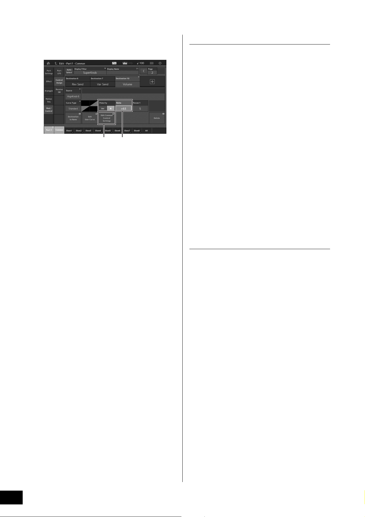
Playing the Keyboard
4-85-1
4-8 Adjust other parameters if necessary.
Here, set the Curve Polarity (Polarity) to “Bi,” and the
Curve Ratio (Ratio) to “+63.”
5 Set the instrument parameters for Part 2.
5-1
Touch the [Edit Common Control Settings] button.
The Control Assign display for Common/Audio Edit
appears.
5-2 Touch the [+] button.
Destination 7 is added.
5-3 On the [Destination 7] tab, set Source to “Asgn
Knob 7,” and [Destination 7] to “Part 2 Assign 7.”
5-4 Touch the [Edit Part 2 Control Settings] button.
Set the parameters the same as the ones for Part 1.
Here, set the Curve Polarity (Polarity) to “Bi,” and the
Curve Ratio (Ratio) to “-64.”
Checking the Super Knob settings
This section covers the procedure to check the parameter
values changed by operation of the Super Knob.
1 Press the [PERFORMANCE (HOME)] button.
The button lights, indicating that you can make common
settings for all Parts.
2 With the [View] button off, press the [ASSIGN]
button to select Common Assign 1–4 or
Common Assign 5–8.
The button lights when Assign 1–4 is selected, and the
button flashes when Assign 5–8 is selected.
The functions currently assigned to Knobs 1–4 (5–8) and
the parameter values are shown.
3 Turn the Super Knob while playing the
keyboard.
All relevant parameter values are simultaneously
changed and all assigned functions are applied to the
sound.
NOTE
For details about Knob assignments and Super Knob settings,
see the Reference Manual PDF document.
Checking parameters assigned to the
Super Knob
This completes the setting.
When further adjustments are needed
• Touch the [Edit Common Control Settings] button, and
switch between Destination 6 and 7, and adjust the
Curve Type or Ratio.
or
• Press KNOB POSITION [1], turn Knobs 6 and 7 to
make a setting for when the Super Knob is turned all
the way to the left, and simultaneously press [SHIFT]
and KNOB POSITION [1] to store the settings. Next,
press the KNOB POSITION [2], turn the knobs again to
make a setting for when the Super Knob is turned all
the way to the right, and simultaneously press [SHIFT]
and KNOB POSITION [2] to store the setting.
To confirm the parameters assigned to Super Knob, open
the Super Knob display.
1 While the Performance Play display is shown,
touch the [Motion Control] tab on the left side
of the display.
2 Touch the [Super Knob] tab on the left side of
the display.
The Super Knob display appears.
3 On the Super Knob display, touch the [Edit
Super Knob].
The Control Assign display appears.
You can see detailed information for the Super Knob
settings within one page. Make adjustments if necessary.
NOTE
The Control Assign display can be opened from the Performance
Edit display, by first touching the [Control] tab on the left side of the
display, and then touching the [Control Assign] tab.
MODX Owner’s Manual
32
Page 37

Playing the Keyboard
1
4
2
5
6
3
Controlling the Super Knob by using a foot
controller
You can control the Super Knob by using a foot
controller (FC7).
1 Connect the foot controller (FC7) to the
FOOT CONTROLLER [1]/[2] jack.
2 Move the cursor to the Performance
name on the Performance Play display
and then press the [EDIT] button.
3 Touch the [Control] tab in the left of the
screen
[Control Number] tab.
4 Set “Foot Ctrl 1” or “Foot Ctrl 2” to
“Super Knob”—depending on which jack
you connected the foot controller (FC7).
Mixing
Each Mixing can contain up to 16 Parts and a separate
Mixing can be created for each Part. You can adjust the
various mixing related parameters for each Part: volume,
pan, etc.
Basic procedure for Mixing
1 Touch the [Mixing] tab on the left side of the
Performance Play display.
The Mixing display appears.
1 Main category for each Part
2 Switching displays between 3-band EQ / 2-band EQ
3 EQ setting for each Part
4 Parameter values for each Part
5 Changing the display for Parts 1–16
6 Changing the display for the audio Parts (Parts 9–16
are not displayed)
2 Press the [PART SELECT MUTE/SOLO]
button
desired Part for which you want to adjust the
parameter values.
NOTE
By touching [Audio] (6) on the screen, the audio Part are
shown. You can set the parameters relating to the audio data
(AD Part) input from the A/D INPUT [L/MONO]/[R] jacks and the
audio data (Digital Part)* input from the [USB TO HOST]
terminal.
*The audio data which is set as “Digital L/R” among device ports
[1]–[16] buttons to select the
3 Move the cursor to the parameters for each
Part and change the parameter values by
turning the Data dial.
NOTE
• For more detailed parameter settings, press the [EDIT] button
in the Mixing display to open the Edit display.
• For details about the Mixing parameters and Mixing Edit, see
the Reference Manual PDF document.
MODX Owner’s Manual
33
Page 38
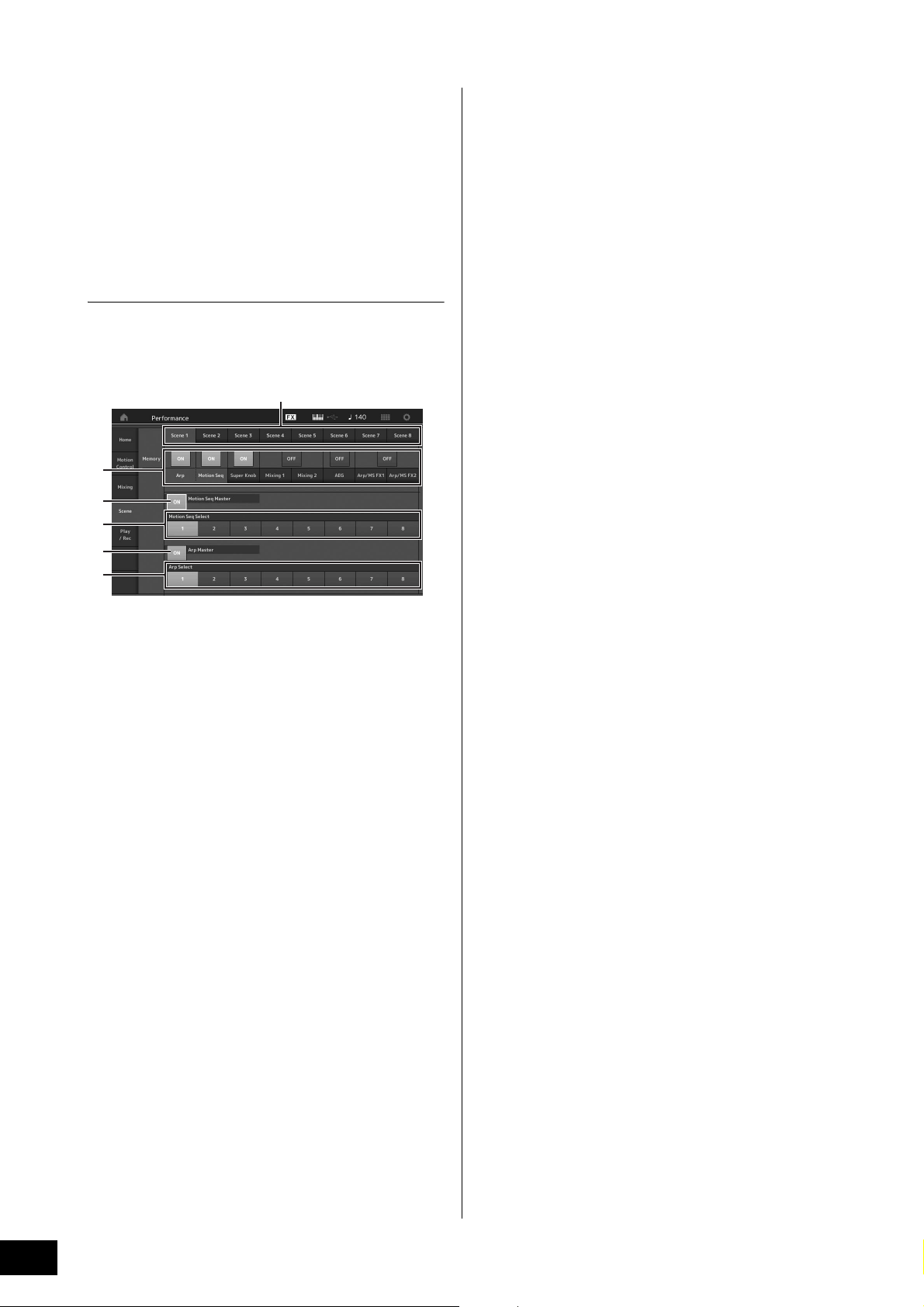
Playing the Keyboard
1
2
4
3
6
5
Using the Scene function
You can store all parameter settings such as Arpeggio type,
Motion Sequencer type, and the Part parameter values
together as a “Scene.” There are eight Scenes and you can
select them by pressing the [SCENE] button.
This is useful for simultaneously and drastically changing the
Arpeggio type and the Motion Sequencer type while you are
playing a single Performance.
Changing Scene settings
1 Touch the [Scene] tab on the left side of the
Performance Play display.
The Scene display appears.
3 Store the Performance as necessary
(page 37).
NOTICE
If you select a different Performance or turn off the power
without storing your edited Performance, all the edits
you’ve made for the Scene will be erased.
1 Switching among Scenes 1–8
2 Turning functions for each Scene on/off
3 Turning the Motion Sequencer for All Parts on/off
4 Motion Sequencer type of the currently selected
Scene
5 Turning the Arpeggio for all Parts on/off
6 Arpeggio type of the currently selected Scene
NOTE
Sections 3 to 6 (see illustration above) are displayed only when
“Arp” and “Motion Seq” are selected in section 2.
2 Set Scenes 1–8 as desired.
When [Memory] is turned on for the function, the Motion
Sequencer type, or the Arpeggio type, the
corresponding function information is automatically
memorized to the currently selected [SCENE] button. By
pressing one of the SCENE [1]–[8] buttons, the Scenes
1–8 are switched and stored information for each Scene
is restored.
NOTE
You can also change Scene Settings from other setting displays.
After changing the parameters from other setting displays using
Knobs or Control Sliders to which you have previously assigned
parameters from the Scene Settings display, press one of the
SCENE [1]–[8] buttons while holding down the [SHIFT] button to
store the settings.
MODX Owner’s Manual
34
Page 39

Creating Your Own Live Sets
The performance registered in the slot
An empty slot
The Live Set is ideal for live performance situations since it lets you instantly switch among desired Performances. You can
create your own Live Set by simply grouping together your favorite Performances.
Registering a Performance to a Live Set
Follow the instructions below to store Performances to Live
Sets.
NOTICE
• Before storing the currently editing Performance to the
Live Set, store the Performance itself (page 37).
• If you select a different Performance or turn off the power
without storing your edited Performance, all the edits
you’ve made will be erased.
1 Select the Performance you want to use.
2 Hold down the [SHIFT] button and press the
[LIVE SET] button.
The Live Set display appears.
Live Set display
Sorting registered Performances in a Live Set
You can change the order of the Performances registered to
a Live Set on the Live Set Edit display.
1 Press the [EDIT] button while the Live Set
display is shown.
The Live Set Edit display appears.
(The Live Set Edit display will not be shown if a Live Set
of the preset bank/library bank is open.)
2 Select the slot containing the Performance
you want to move and touch [Swap] on the
screen.
The [Swap] lights up and now the slot can be changed.
3 Touch one of the slots. The currently selected
Performance will be registered in the slot.
3 Select the desired destination slot.
The original slot and the destination slot are switched
with each other.
MODX Owner’s Manual
35
Page 40

Creating Your Own Live Sets
Switching Performances stored in a Live Set
by using the footswitch
You can switch the Performances by using a
connected footswitch (FC4 or FC5). The setting for this
operation is as follows.
1 Connect the footswitch (FC4 or FC5) to
the FOOT SWITCH [ASSIGNABLE] jack.
2 Press the [UTILITY] button to call up the
Utility display, and then touch [Settings]
tab
[MIDI I/O] tab at the left side of the
screen.
3 Set “FS Assign” to “Live Set +” or “Live
Set -.”
When “Live Set +” is selected, the Performances
are switched in forward order. When “Live Set -” is
selected, the Performances are switched in reverse
order.
MODX Owner’s Manual
36
Page 41

Editing the Settings
Storing a new Performance
Performance previously stored
This instrument has various edit displays for Parts, Performances, effects, and Arpeggios. This chapter explains how to create
an original Performance by combining multiple Parts.
Performance Editing
“Performance Editing” refers to the process of creating a
Performance by changing the parameters that make up the
Performance. This can be done in the Performance Edit
display.
Basic operations for editing a
Performance
1 Move the cursor to the Performance name on
the Performance Play display, then press the
[EDIT] button.
2 Touch the [General] tab at the left side of the
screen to edit the Performance.
Performance Edit display
1 Press the [STORE] button to call up the Store
display.
2 Set the destination for storing the
Performance.
To store the newly edited Performance, touch “+” in the
[Store As New Performance] section.
NOTE
To overwrite the previously stored Performance, touch [Overwrite
Current Perf.] or the Performance to be overwritten.
Storing the Performance (Store)
After editing, store the Performance to internal memory.
Press the [STORE] button to store the Performance.
NOTICE
• The edited Performance will be lost when selecting a different
Performance or turning the power off.
• If you overwrite a Performance in the User bank, it will be permanently deleted. When you store the edited Performance, be
careful not to overwrite any important User Performances.
Important data should always be saved to a USB flash drive
connected to the [USB TO DEVICE] terminal. For detailed
instructions on saving, see page 60.
NOTE
You can select any desired Part by using the [PART SELECT MUTE/
SOLO] buttons during editing of the Performances, and edit the
selected Part.
3 The Text Input display appears. Input the
name of the stored Performance.
For detailed instructions on inputting characters, see
“Naming (character inputting)” in “Basic Operation and
Displays” (page 21).
4 Select “Done” on the Text Input display to
actually execute the Store operation.
NOTE
If you are overwriting the previously stored file, a confirmation
display appears after Step 2. Select “YES” to execute the Store
operation.
MODX Owner’s Manual
37
Page 42
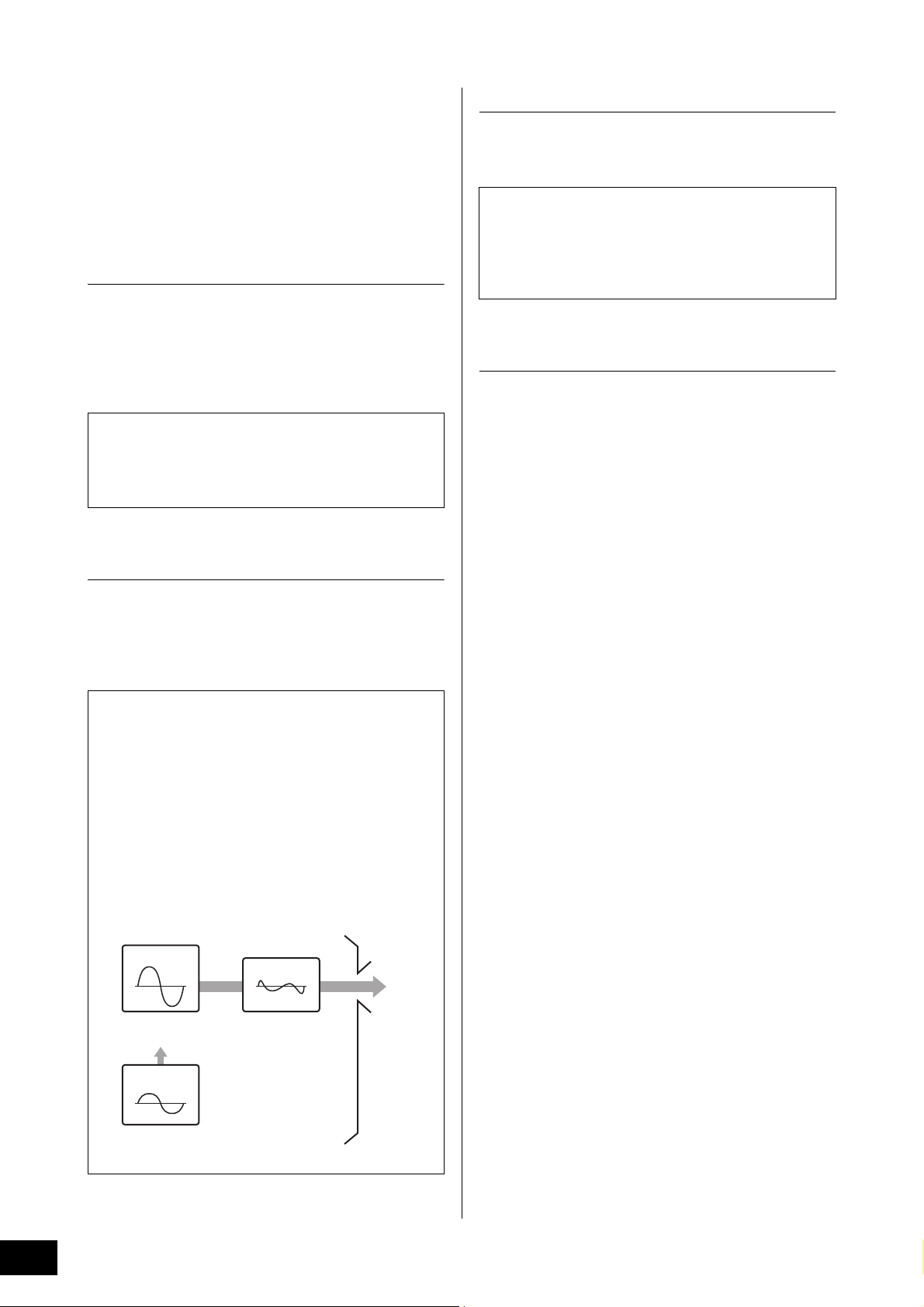
Editing the Settings
Carrier
Waveform to be
modulated
Sound output
Modulator
Modulated
waveform
Modulating
waveform
When the volume of the
modulator increases, the
carrier waveform changes.
* The carrier waveform is not
affected when the volume
is 0.
Part Editing
“Part Editing” refers to the process of creating a Part by
changing the parameters that make up the Part. This can be
done in the Element Common/Key Common/Operator
Common Edit display and the Element/Key/Operator Edit
display. The actual parameters that are available differ
depending on the Part type.
Normal Part (AWM2) Edit
A Normal Part (AWM2) (having pitched musical instrument
sounds) can consist of up to eight Elements. An Element is
the basic, smallest unit for a Part. There are two types of
Normal Part (AWM2) Edit displays: Element Common Edit
display, for editing settings common to all eight Elements;
and Element Edit display, for editing individual Elements.
An Element is created by applying various parameters
(Effect, EG, etc.) to the waveform of the instrument sound.
A Normal Part of this instrument (AWM2) consists of up to
eight Elements.
Normal Part (FM-X) Edit
A Normal Part (FM-X) (assigned FM-X sounds) can consist of
up to eight Operators. There are two types of Normal Part
(FM-X) Edit displays: Operator Common Edit display, for
editing settings common to all eight Operators; and Operator
Edit display, for editing individual Operators.
Drum Part Edit
There are two types of Drum Part Edit displays: Key
Common Edit display, for editing the settings that apply to all
Drum keys; and Key Edit display, for editing individual keys.
Drum Parts are mainly percussion/drum sounds that are
assigned to individual Keys. You can create various drum
Parts by changing assigned sound types and adjusting the
pitch and EQ.
Drum Parts of this instrument consist of up to 73 Keys.
Basic operation of Part Edit
1 Move the cursor to the Part you want to edit
in the Performance Play display, then press
the [EDIT] button.
You can also use [PART SELECT MUTE/SOLO] button to
select a Part.
2 Touch the [Part Settings] tab at the left side of
the screen
Part.
For Normal Parts (AWM2)
For Element Common Editing, touch the Element
[Common] tab.
For Element Editing, press the corresponding Number
button of the element to be edited from among the
[Elem1]-[Elem8] tabs.
[General] tab to edit the desired
The abbreviation “FM” of FM-X stands for “frequency
modulation,” which is special tone generation system that
uses one waveform’s frequency to modulate another
waveform, to produce a completely new one. Waveforms
are generated by “operators,” of which the MODX has
eight. An operator that generates a fundamental waveform
is a “carrier,” and an operator that modulates these
waveforms is a “modulator.” Each of the eight operators
can be used as either a carrier or a modulator. By
changing the way operators are combined and controlling
the modulation with other parameters such as levels and
envelopes, you can create richly textured sounds that
change in a highly complex fashion.
For Drum Parts
For Key Common Editing, touch the Drum Key
[Common] tab.
For Key Editing, press the tab corresponding to the Drum
Part you want to edit (BD, SD, etc.).
You can switch the Keys of each instrument sound
(assigned to C1 to C#2) by using the [BD]–[Crash] tabs.
For selecting Keys other than the Keys assigned to C1 to
C#2, turn on “Keyboard Select” on the display and play
the note assigned the Key to be edited.
For Normal Parts (FM-X)
For Operator Common Editing, touch the Operator
[Common] tab.
For Operator Editing, press the corresponding Number
button of the operator to be edited from among the
[OP1]–[OP8] tabs.
NOTE
For details about the Part parameters, see the Reference Manual
PDF document.
MODX Owner’s Manual
38
Page 43
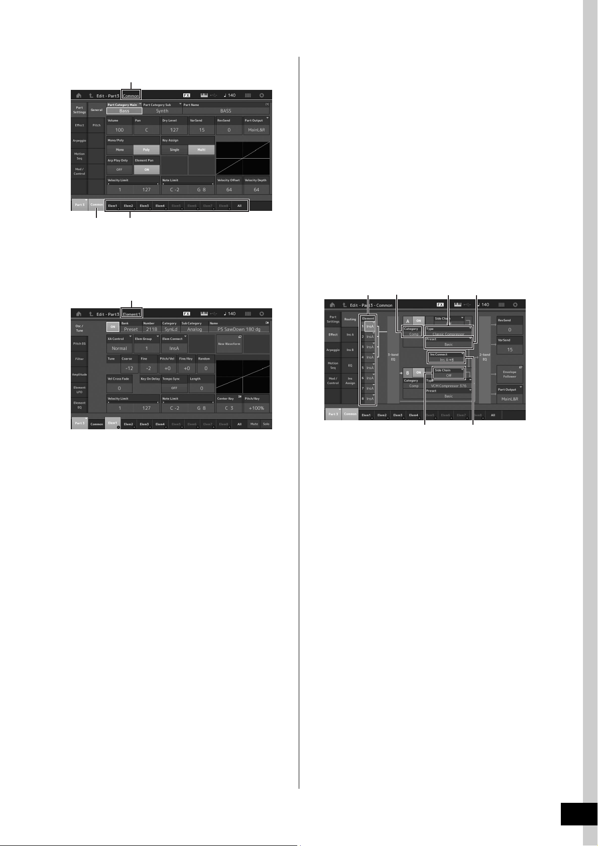
Editing the Settings
Indicates that the Element Common Edit display is active.
Switches between Element Common Edit and Element Edit.
Indicates that the Element Edit display is active.
2
Element Common Edit display
The structure of the display is the same as for the Key/
Operator Common Edit display.
Element Edit display
Part Effect Editing
This instrument features a wide variety of Effects, letting you
add Variation and Reverb processing to the selected Part for
your keyboard performance. Simply changing the Effect
type applied to the preset Part lets you instantly come up
with different sounds. The instructions below explain how to
set the Effect type and the related parameters applied to the
Part, and then store the settings as a User Performance.
1 Move the cursor to the Part to be edited on
the Performance Play display, and then press
the [EDIT] button.
2 Touch the Element [Common] button.
3 Touch the [Effect] tab in the left of the screen
[Routing] tab.
The Effect display for Element Common Edit appears.
31
4
The structure of the display is the same as for the Key/
Operator Edit display.
3 Store the Performance as necessary.
6
1 Output of each Element/Key
2 Category of Insertion Effect A
3 Type of Insertion Effect A
4 Preset of Insertion Effect A
5 Connection method between Insertion Effects A and
B
6 Selection of Side Chain/Modulator
5
4 Set the output of each Element/Key (1).
5 Select the parameters (Effect category (2),
Effect type (
corresponding to Insertion Effect A.
3), and Effect preset (4))
6 Set the connection method between Insertion
Effects A and B (
5).
7 Set the Side Chain/Modulator of Insertion
Effect B (
NOTE
The Side Chain/Modulator uses the output from one track to
control an effect in a different track. You can specify the Effect
type for activating the feature so that input signals for Parts other
than the selected Part or the audio input signal can control the
specified Effect.
This trigger is called “Side Chain” or “Modulator” depending on
the Effect Type.
6).
MODX Owner’s Manual
39
Page 44

Editing the Settings
Strings having a fast attack speed
Strings having a slow attack speed
Par t 2
Par t 1
Part 2Part 1
Strings
Flute
C1 C2 C3 C4 C5 C6
Orchestra Hit
Strings having fast attack speed
Strings having slow attack speed
Part 3
Part 2
Part 1
Vel oc it y
8 Touch the [Ins A] tab at the left side of the
screen.
The display for editing effect parameters selected in
Step 4 appears.
9 Set the parameters as necessary.
Try narrowing in on your desired sound by finely editing
the parameters provided for each Effect Type.
Compare function
The Compare function lets you switch between the justedited sound and its original, unedited condition, allowing
you to hear how your edits affect the sound.
Press the [EDIT] button while the Edit display is shown, so
that the [EDIT] button flashes. In this status, the sound
settings prior to editing will temporarily be reinstated for
comparison purposes. Press the [EDIT] button again to
return to the original status.
10 Edit Insertion Effect B by using the same
operation.
11 Store the Performance as necessary.
How Parts are assigned to a Performance
By default (when shipped from the factory), various types of
Performances are provided in the Preset Banks. For some of
these Performances, it may not be immediately obvious how
to play them or use them, since they are quite complicated.
In this section, you’ll learn the typical ways in which
Performances are created, and thus better understand how
to play and use them. This section covers the typical four
Part assignments.
Performance Structure Layer
This method lets you play multiple (two or more) Parts
simultaneously by pressing any notes.
For example, you can create a thicker sound by combining
two similar Parts—for example, two different Strings Parts,
each with a different attack speed.
C1 C2 C3 C4 C5 C6
Performance Structure Split by Note range
This method lets you play different Parts with your left hand
and right hand. By assigning a Strings Part to the lower
range and assigning a Flute to the higher range separately
as illustrated below, you can play Strings accompaniment
with your left hand and while playing Flute melody with your
right hand.
40
MODX Owner’s Manual
C1 C2 C3 C4 C5 C6
Performance Structure
Split by Velocity range
This method lets you trigger different Parts depending on
your playing strength (velocity). In this example below,
playing notes at low velocities triggers Strings sounds with a
slow attack speed. Playing notes at middle velocities
triggers Strings sounds with a fast attack speed. Playing
notes at high velocities triggers Orchestra Hits.
Page 45

Editing the Settings
C1 C2 C3 C4 C5 C6
Par t 3
Par t 4
Par t 1
Guitar with Arpeggio
Piano with Arpeggio
Bass with Arpeggio
Drums with Arpeggio Hold set to ON
Part 2
Performance Structure Using Arpeggios
With this method, you can play all the parts of a band by
yourself. With the MODX, you can assign different Arpeggio
types to each of the eight Parts in a Performance. For
example, you could assign four different Arpeggio types to
four Parts, as shown below, so that Bass Arpeggios are
played on the lower range of the keyboard, Guitar and Piano
Arpeggios on the upper range, and Drum Arpeggios on all
ranges of the keyboard. Then, by simply playing the
appropriate ranges of the keyboard, you can add full,
dynamic accompaniment to your performance.
In addition, you can change the Arpeggio Type assignment
from [Motion Control]
you to set different Arpeggio Types for the intro, verse,
chorus, and ending of your song.
Using or combining the four methods described above gives
you the ability to create a rich variety of Performances. By
default, many Performances stored in the Preset Banks have
been created via the above methods. Try out various
Performances and see which method is used for each.
[Arpeggio] on the display, allowing
Creating a Performance by combining Parts
After checking out the pre-programmed Performances in the
Preset Banks, try creating your own original Performance. In
this section, we’ll create a Performance by combining two
Parts.
Selecting a Performance
For demonstration purposes, we’ll assign a piano sound to
Part 1.
1 Move the cursor to the Part name of the Part 1
on the Performance Play display and press
the [CATEGORY] button while holding down
the [SHIFT] button.
The Part Category Search display appears.
2 Select [Full Concert Grand] from the
Performance list.
3 Press the [EXIT] button.
Playing several Parts together (Layer)
Try combining two Parts by assigning a favorite Part to
Part 2.
1 Move the cursor to the Part name of the Part 2
on the Performance Play display and select
the desired sound by pressing the
[CATEGORY] button while holding down the
[SHIFT] button.
2 Play the keyboard.
The Part 1 (Piano) and Part 2 (the sound you have
selected above) are sounded simultaneously in a layer.
3 Press the [EXIT] button.
Next, let’s play different Parts with the left and right hands.
MODX Owner’s Manual
41
Page 46
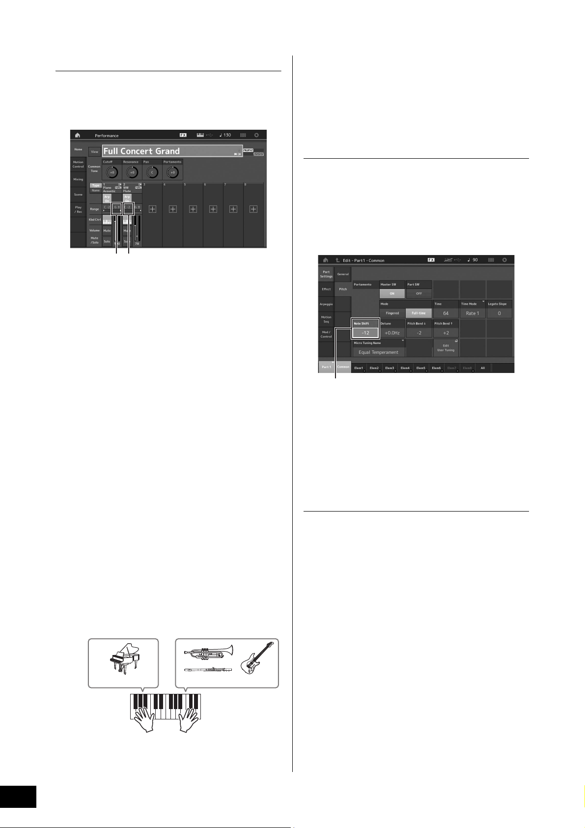
Editing the Settings
12
Part 1: Piano Part Part 2: Other Part
Note Shift
Split
You can play different Parts with the left and right hands by
assigning one Part to Part 1, with a note range in the lower
section of the keyboard, and a different Part to Part 2, with a
note range in the higher section of the keyboard.
1 Note Limit Low (the lowest note of the range for the Part)
2 Note Limit High (the highest note of the range for the
Part)
1 Touch the Note Limit High (2) of Part 1 or
move the cursor to
button.
2 and press the [ENTER]
8 Press the Slider Function [PART]/[ELEMENT/
OPERATOR] button to select “PART.”
9 Use the Control Sliders 1 and 2 to adjust the
volume for Parts 1 and 2.
Changing the note range of the split Part
to one octave lower
Change the note range of Part 2 to one octave lower.
1 Move the cursor to Part 2 and press the
[EDIT] button for Part edit.
2 Touch the [Part setting] tab at the left side of
the screen
[Pitch] tab.
2 Touch the [Keyboard] menu at the left side of
the screen to turn it on.
3 Set the highest note of Part 1 by pressing the
corresponding key.
The note number in the Range section of Part 1 changes.
4 Touch the Note Limit Low (1) of Part 2 or
move the cursor to
button.
1 and press the [ENTER]
5 Set the lowest note of Part 2 by pressing the
corresponding key.
The note number in the Range section of Part 2 changes.
6 Touch the [Keyboard] menu at the left side of
the screen to turn it off.
7 Play the keyboard.
The notes you play with your left hand sound the Piano
Part (Part 1), while the notes you play with your right
hand sound the different Part (Part 2) you have selected.
3 Select “Note Shift” to adjust the Pitch.
The pitch is shifted in semitone steps. Set “-12” to make
the note range one octave lower.
4 Play the keyboard.
Changing the Arpeggio settings for each
Part
Try changing the Arpeggio settings for each Part. You can
assign the rhythm or backing pattern that best matches the
desired style of music to the Performance.
1 Move the cursor to Part 1 and press the
[EDIT] button to call up the Element Common
Edit display.
2 Touch the [Arpeggio] tab at the left side of the
screen
display).
The display for setting common Arpeggio parameters for
all Arpeggio type appears.
Note that the Arpeggio Hold parameter is useful as well
as the Arpeggio type selection. When this parameter is
set to “on,” the Arpeggio playback continues even if the
note is released. This parameter should be set to “on”
when a Drum sound is assigned to the Part and you wish
to have playback of the Arpeggio (rhythm pattern)
continue regardless of whether you hold the note or not.
[Common] tab (near the top of the
MODX Owner’s Manual
42
Page 47
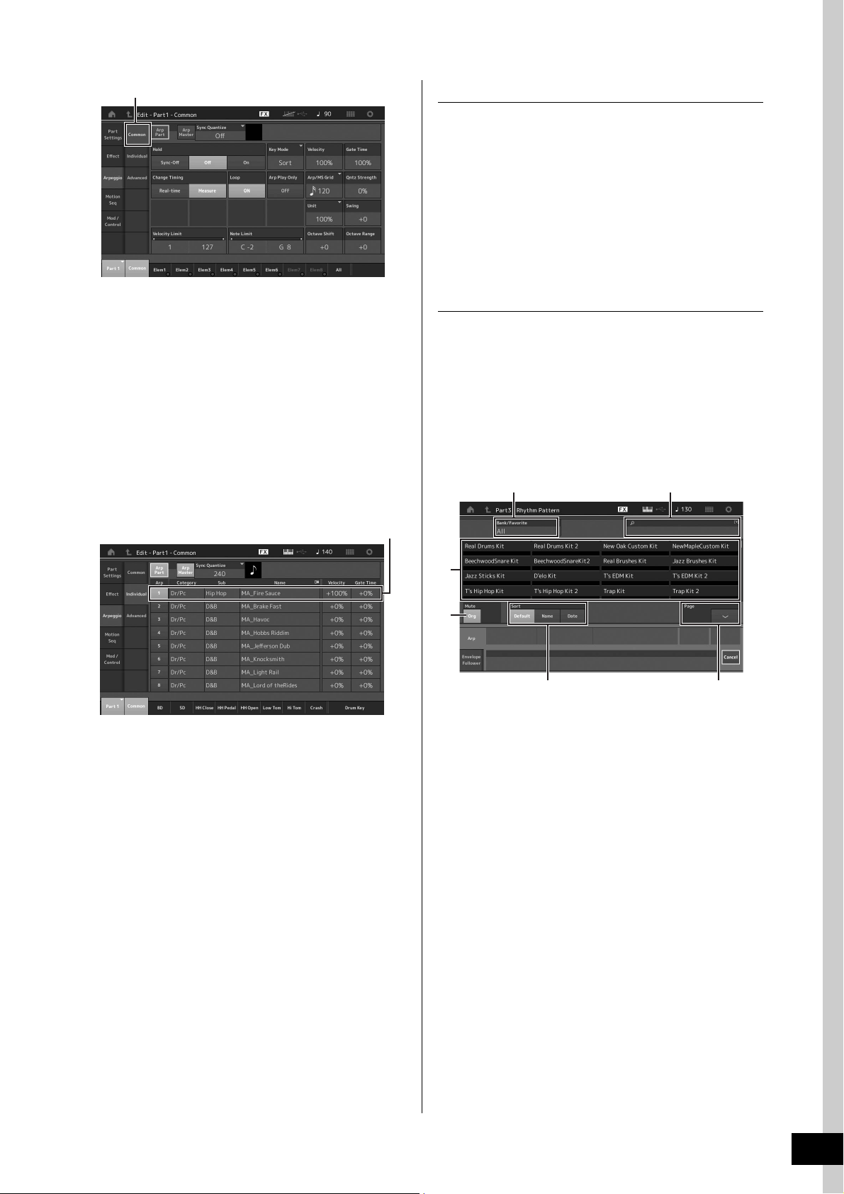
Editing the Settings
[Common] tab
Setting of Arpeggio type
3
4
1 2
5 6
Using the Rhythm Patterns
The [Rhythm Pattern] button provides a simple way to add a
rhythm part to the current Performance.
By combining rhythm patterns and the Envelope Follower,
you can modify the patterns even further.
Here, as an example, we explain how to add the rhythm
pattern “8Z Trance Basics 1” to the Performance
“Supertrance,” and then modify the sound with the Envelope
Follower.
3 Touch the [Individual] tab to call up the
setting display for each Arpeggio Type.
4 Touch the Arpeggio type and select the
[Category Search] menu at the left side of the
screen. (Alternately, you can press the
[CATEGORY] button.)
The Category determines the instrument type and the
Sub Category determines the music type.
The Arpeggio types include variations for each section of
the song, such as intro, verse, refrain, chorus, and
bridge. Play the keyboard to hear the arpeggios to select
one you like.
Adding a Rhythm Part (simple way)
1 Select the desired Performance for adding
the rhythm part.
Here, select “Supertrance.”
2 Press the [RHYTHM PATTERN] button.
The Rhythm Pattern display appears.
When all of the parts in Part 1 to 8 are already in use, the
message “Part Full” appears and the rhythm pattern
cannot be added.
Go on and assign other Arpeggio types in the same way
as desired.
5 Store the Performance as necessary.
1 Bank/Favorite
2 Name Search
3 Kit Selection
4 Mute
5 Sort
6 Switching pages
3 From the Rhythm Pattern List, touch the
Rhythm Pattern kit you want to use.
Here, touch “8Z Trans Basics1.”
A rhythm part is added.
4 Play the keyboard and the rhythm pattern
starts playing.
MODX Owner’s Manual
43
Page 48

Editing the Settings
5 Press the [PERFORMANCE (HOME)] button
or [EXIT] button to set the Rhythm Pattern.
The Rhythm Pattern display closes.
NOTE
You can also touch the HOME icon to confirm the selection.
6 To stop the rhythm pattern, press the [ARP
ON/OFF] button or the [J] (Stop) button.
NOTE
You can also stop the rhythm pattern by touching the [Arp Hold
On] button on the display.
Setting the Envelope Follower
Envelope Follower is a feature that extracts the envelope (or
amplitude envelope) of a waveform from the input signals,
and then lets you use that envelope as a controller for
modifying sounds. For example, by assigning a rhythm
pattern to a Part and setting the Envelope Follower of the
Part as a “Source,” the sound of other Parts are modified
accordingly. This is especially useful for automatic
“ducking,” where you want to lower the volume of other
instruments while a certain instrument sound is being
played.
3 Adjust settings as needed.
Here, in this example, set the Curve Polarity (Polarity) to
“Bi,” the Curve Ratio (Ratio) to “-63,” and the Gain (Gain)
to “-12dB.”
For setting other parameters, touch the [EDIT] button on
the screen, and open the Envelope Follower Setting
display.
When you want to change the Rhythm Pattern kit or the
Arpeggio Type, press the [RHYTHM PATTERN] button to go
back to the Rhythm Pattern display. The Envelope Follower
settings are retained even after the new kit or the Arpeggio
type is selected.
1 Touch the [Envelope Follower] tab at the
bottom of the Rhythm Pattern display.
The Envelope Follower display appears.
2 Turn the Envelope Follower switch “ON.”
Here, you can play the keyboard to hear the sound with
the Envelope Follower enabled.
MODX Owner’s Manual
44
Page 49

Recording and Playback
1
4
)
7
9
2
You can record MIDI data as Songs on this instrument itself or record your performance (audio data) on a USB flash drive
plugged into the MODX.
Terminology
Song
A Song on this instrument is effectively the same as a song
on a MIDI sequencer, and playback automatically stops at
the end of the recorded data. The MODX can store up to 128
Songs.
Tra ck
This is a memory location on the sequencer where your
musical performances (made up of MIDI events) are stored.
The MODX provides 16 tracks, which correspond to the 16
Mixing Parts.
Realtime Recording
The instrument records the performance data as it is played
along with a metronome. Realtime Recording features three
available methods: Replace, Overdub and Punch In/Out.
• Replace lets you overwrite an already recorded Track with
new data, erasing the previously recorded data.
• Overdub lets you add more data to a Track that already
contains data—in other words, recording new notes on top
of the previous ones.
• Punch In/Out lets you re-record selectively over a specific
area of the Track.
MIDI Recording
This instrument features a Performance Recorder (built-in
multi Track sequencer) for recording your keyboard
performance as MIDI data. This function allows you to
instantly store your phrase which comes to your mind. You
can create full, complex multi-instrument arrangements and
complete Songs, using DAW.
Recording to a track
In this section, you’ll learn how to record your keyboard
performance, by recording a part to Track 1. However, you’ll
first need to set up the MODX for recording.
1 Touch the [Play/Rec] tab in the left of the
Performance Play display.
The recording display appears.
2 Touch the [MIDI] tab in the left of the screen.
3 Press the [I] (Record) button.
The Record Setup display appears.
NOTE
Alternately, you can simply press the [I] (Record) button in the
Performance display, to perform Steps 1–3 at once.
3
5
6
8
1 Song name
2 Currently selected Performance name
3 Time Signature (Meter)
4 Position (starting position of Recording/Playback)
5 Quantize
6 Position corresponding to the entire sequence
7 Recorded time of the entire sequence
8 Playback on/off for each track
9 Shortcut to the Tempo Settings display
) Changing the tempo
4 Set the following parameters on the Record
Setup display.
4-1
Move the cursor to Time Signature (Meter) (3), and
then set the value. For this example, set this to “4/4.”
4-2 Set Quantize to “240 (8th note)” in Record Quantize
(5). This convenient feature lets you automatically
quantize (or “clean up” the timing of) the notes in real
time, as you record. Quantize aligns the timing of note
events to the nearest beat. Normally, the smallest note
value in the notation (if you're playing from sheet music)
should be set.
5 After completing recording setup, press the
[R] (Play) button to start recording.
Press the [R] (Play) button, then actually start recording
after the count-in.
6 When you’ve finished playing, press the
[J] (Stop) button to stop recording.
If you’ve played any wrong notes, press the [J] (Stop)
button, then try recording again.
MODX Owner’s Manual
45
Page 50

Recording and Playback
1234567 8
1234567 8
Before re-recording
Recording start Recording stop
Punch In point
Punch Out point
After re-recording
Newly recorded data
231
1
2
Recording with the click
Follow the steps below to use the click during MIDI
recording.
1 Press the [UTILITY] button and touch [Tempo
Settings] (or Touch the [Click Settings] button
where available) on the screen to call up the
Tempo settings display. Set the Click “Mode”
to “Rec.”
NOTE
When “Rec/Play” is set, the click sounds during MIDI recording
and playback. When “Always” is set, the click will always
sound.
3 Punch Out: 006:01
Recording ends at this point and normal playback of
the recording Track starts.
Cancelling your most recent recording
(Undo/Redo)
The Undo Job cancels the changes you made in your most
recent recording session and restores the data to its
previous state. Redo is available only after using Undo,
and lets you restore the changes you made before undoing
them.
Re-recording a specific part of a Song
(Punch In/Out)
Use the Punch In/Out recording method to record over only
a specific portion of the Track. If you set the start point
(Punch In) and end point (Punch Out), and then start
recording from the top of the Song, the actual recording
will be done only between the Punch In and Punch Out
points. In the eight-measure example below, only the third
through the fifth measures are re-recorded.
NOTE
Note that the Punch In/Out method always replaces (destroys)
the original data over the specified area.
To execute Punch In/Punch Out recording in the above
condition, set the following parameters beforehand on the
Record Setup display.
1 “Record Type”: “punch”
2 Punch In: 003:01
Playback of the recording Track is turned off from this
point, and your keyboard performance will be
recorded to the Track.
1 Undo (This display is not available if nothing has been
recorded.)
When [Undo] is touched, the display prompts you for
confirmation. Selecting Undo cancels the previous
recording.
2 Redo (This display is not available if Undo has not
been operated.)
When [Redo] is touched, the display prompts you for
confirmation. Selecting Redo restores the change you
made.
MODX Owner’s Manual
46
Page 51

Recording and Playback
Stop Play
[PART]/[ELEMENT/OPERATOR] button
Slider Select [1–4] [5–8] buttons
2
4
3
5
1
Playing a Song
In this section, you’ll learn how to use convenient mute/solo
functions while playing back a recorded song.
Song playback
1 Press the [R] (Play) button to start the Song.
NOTE
To adjust the volume level of the Songs, use the [MASTER
VOLUME] knob.
2 Press the [J] (Stop) button to stop the Song.
Recording your performance as audio
Your performances on the MODX can be recorded as WAV
format (44.1-kHz, 24-bit, stereo) audio files to a USB flash
drive. The recording level is fixed, and it is possible to record
continuously for up to 74 minutes (assuming that the USB
storage device has sufficient free memory).
NOTICE
The MODX should never be turned off during recording,
playback, or while the recorded audio file is being saved.
Turning off the MODX at that time may make it impossible to
subsequently access the USB flash drive.
1 Connect a USB flash drive to the [USB TO
DEVICE] terminal of the MODX.
2 Touch the [Play/Rec] tab in the left of the
Performance Play display.
The recording display appears.
3 Touch the [Audio] tab in the left of the screen.
4 Press the [I] (Record) button to setup the
audio recording.
The Record Setup display appears.
Adjusting the volume of each Part
You can adjust the volume for each of four Parts, using the
Control Sliders.
You can change the volume for Parts 5–8 by first pressing
the [PART]/[ELEMENT/OPERATOR] button to select PART,
and then pressing the Slider Select [1–4] [5–8] button.
In addition to sliders, the Knobs 1–4 (5–8) can be used to
affect the Part setting of the Song playback in real time. For
details, refer to the Reference Manual PDF document.
1 Play position
2 Current play position in the entire audio data
3 Available recording time
4 Level meter
5 Trigger level
5 Set the required trigger level (5).
If you set the trigger level to “manual,” recording will
begin whenever you press the [R] (Play) button.
Alternatively, if you set a value between 1 and 127,
recording will begin automatically whenever the
playback volume exceeds that level. The level set here
will be indicated by blue triangles in the level meter (4).
For best results, set this parameter as low as possible to
capture the entire signal, but not so low as to record
unwanted noise.
MODX Owner’s Manual
47
Page 52

Recording and Playback
1
6 Press the [R] (Play) button.
If you have set the trigger level to “manual,” recording
will begin immediately right after you press the [R] (Play)
button. While the recording, the [I] (Record) button will
light red and the [R] (Play) button will light green. If you
have set a value between 1 and 127 as the trigger level,
the recording will begin automatically whenever the
playback volume exceeds that level.
7 Play the keyboard.
If you set the trigger level to a value between 1 and 127,
recording will begin automatically whenever the
playback volume exceeds that level.
8 When you have finished playing, press the
[J] (Stop) button.
The recorded audio file will be saved on the selected
device.
Playing an audio file
As described below, the MODX can play audio files (.wav)
from a USB flash drive, regardless of whether they have
been created by the instrument itself or come from another
source.
1 Connect a USB flash drive to the [USB TO
DEVICE] terminal of the MODX.
2 Touch the [Play/Rec] tab [Audio] tab at the
left side of the Performance display.
3 Touch “Audio Name” and then select [Load]
menu at the left side of the screen.
4 Select the source USB flash drive and folder.
5 Select the desired file (.wav) on the USB flash
drive to execute the Load operation.
2
1 Audio name
2 Audio volume
3 Audio length
6 Press the [R] (Play) button.
The audio file will begin playing.
7 Move the cursor to “Audio Volume” (2), and
then adjust the playback volume by using the
data dial.
8 Press the [J] (Stop) button to stop playback.
NOTE
Keep in mind that you can also play a selected Performance on
the keyboard during audio playback.
3
MODX Owner’s Manual
48
Page 53

Using as a Master Keyboard
The Master Keyboard function lets you assign up to eight separate Zones in each Performance for use as a master keyboard
controller.
You can call up the settings for controlling an external MIDI device instantly anytime you need by combining with the Live Sets.
Accordingly, you can change and control the connected external MIDI tone generator in sequence while performing live.
Making settings for use as a master keyboard—Zone
When you use the MODX as a master keyboard, you can
divide the keyboard into a maximum of eight independent
areas (called “Zones”). Different MIDI channels and different
functions of the Knobs and Control Sliders can be assigned
to each Zone. This makes it possible to control several Parts
of the internal multi-timbral tone generator simultaneously by
a single keyboard, or control Performances of an external
MIDI instrument over several different channels in addition to
the internal Performances of this synthesizer itself—letting
you use the MODX to effectively do the work of several
keyboards. You can set the parameters related to the eight
Zones and store the settings.
First, set the MODX as a master keyboard by activating the
Zone settings.
1 Press the [UTILITY] button to call up the
Utility display.
2 Touch the [Settings] tab [Advanced] tab at
the left side of the screen.
Next, make settings according to the Master Keyboard
(Zone) for each Performance.
1 Press the [PERFORMANCE (HOME)] button
to call up the Performance Play display.
2 Move the cursor to the desired Part of the
currently selected Performance and press the
[EDIT] button to edit the Part.
3 Touch the [Part Settings] tab [Zone
Settings] tab at the left side of the screen.
4 Touch [Zone] to turn it on.
5 Set the Zone related parameters such as MIDI
transmit channel and Note Limit.
3 Touch [Zone Master] to turn it on.
4 Press the [EXIT] button.
This stores the setting and returns to the previous
display.
6 Touch the [Zone Transmit] tab to set the
transmit switches as desired.
After completing these settings, press the [STORE] button to
store the Performances.
For details about Zone settings, see the Reference Manual
PDF document.
MODX Owner’s Manual
49
Page 54

Connecting a Microphone or Audio Equipment
L
R
Stereo audio equipment (CD player, etc.)
A/D INPUT [L/MONO] A/D INPUT [R]
Microphone
A/D INPUT [L/MONO]
Playing the keyboard along with the sound input from the A/D INPUT [L/MONO]/[R] jacks
You can have the A/D input sound—such as your voice
through a microphone, a CD player, or a synthesizer—
assigned as an Audio Input Part. Various parameters such
as volume, pan, and effects can be set to this Part and the
sound is output together with the sound of your keyboard
performance.
1 Make sure to turn off the power of this
instrument and set the A/D INPUT [GAIN]
knob to the minimum.
2 Connect the audio equipment or the
microphone to the A/D INPUT [L/MONO]/[R]
jack(s) on the rear panel.
5 Set the “Mic/Line” parameter according to the
particular equipment connected to the A/D
INPUT [L/MONO]/[R] jacks.
When connecting equipment of low output level such as
a microphone, set this parameter to “Mic.” When
connecting equipment of high output level (such as a
synthesizer keyboard, CD player, portable music player),
set this parameter to “Line.”
6 Press the A/D INPUT [ON/OFF] button so that
its lamp lights.
This setting enables audio signals to be input from the
connected audio device.
NOTE
A standard dynamic microphone is recommended. (This
instrument does not support phantom-powered condenser
microphones.)
3 Turn on the connected audio equipment, then
turn on the MODX.
4 Press the [UTILITY] button to call up the
Utility display, and touch the [Settings] tab
[Audio I/O] tab at the left side of the screen.
7 Adjust the input level by using the [GAIN]
knob.
NOTE
Adjust the input level with the [GAIN] knob so that the PEAK LED
lights briefly only at the loudest input sounds.
8 Press the [PERFORMANCE (HOME)] button,
and then select the desired Performance.
Play the keyboard wile you sing into the microphone or
play back the audio equipment.
MODX Owner’s Manual
50
Page 55

Making Global System Settings
You can set various parameters in the Utility display. In particular, you can set the parameters that apply to the entire system of
this instrument by touching the [Settings] tab. The changes you make in the Utility display are activated once you press the
[EXIT] button to return to the original display. This section describes some useful functions related to the entire system settings.
Setting automatic power-on tasks
You can determine which display is automatically called up
when power is turned on: the Live Set display or the
Performance Play display.
1 Press the [UTILITY] button to call up the
Utility display, then touch [Settings] tab
[System] tab.
2 In [Power on Mode], select “Live Set” (Live
Set display) and the slot number, or
“Perform” (Performance Play display) as the
start-up display.
Turning various functions on/off
You can set various functions by touching the [System] tab
on the Utility display.
Turning animation on/off
You can turn the animation of screen transition on/off as
follows.
1 Press the [UTILITY] button to call up the
Utility display, then touch [Settings] tab
[System] tab.
2 Select “ON” or “OFF” in “Animation” to turn
the animation on or off.
3 Press the [EXIT] button.
This stores the setting and returns to the previous
display.
Setting button lamp behavior
You can control the dimming of the button lamps.
1 Press the [UTILITY] button to call up the
Utility display, then touch [Settings] tab
[System] tab.
2 Set “Half Glow” to “Off,” “1/4,” or “1/2.”
When “Off” is selected, the dimming function is turned
off.
When “1/4” is selected, the brightness of the button in
the dimly lit condition is reduced to 25% of the fully lit
condition. This lighting level is suitable for dark
surroundings, such as a stage.
When “1/2” is selected, the brightness of the button in
the dimly lit condition is reduced to 50% of the fully lit
condition. This lighting level is useful in bright
surroundings (such as outdoors) when it is hard to
distinguish whether the button is dimly lit or off.
3 Press the [EXIT] button.
This stores the setting and returns to the previous
display.
3 Press the [EXIT] button.
This stores the setting and returns to the previous
display.
Turning display blur effect on/off
When any display is selected, the display previously
selected is blurred. You can turn the function on/off as
follows.
1 Press the [UTILITY] button to call up the
Utility display, then touch [Settings] tab
[System] tab.
2 Set “Blur” to “ON” or “OFF” to turn the blur
effect on or off.
3 Press the [EXIT] button.
This stores the setting and returns to the previous
display.
MODX Owner’s Manual
51
Page 56

Making Global System Settings
Tune
Turning the beep sound on/off
You can turn the beep sound (that confirms operations,
menu/parameter selection, etc.) on/off as follows.
1 Press the [UTILITY] button to call up the
Utility display, then touch [Settings] tab
[System] tab.
2 Set “Beep” to “ON” or “OFF” to turn the beep
on or off.
3 Press the [EXIT] button.
This stores the setting and returns to the previous
display.
Turning the flashing of the Super Knob
on/off
In the default setting, the Super Knob flashes at the current
beat. You can turn this flashing on/off as follows.
When the function is turned off, the Super Knob remains lit
continuously.
1 Press the [UTILITY] button to call up the
Utility display, then touch [Settings] tab
[System] tab.
2 Select “ON” or “OFF” in “Knob Flash” to turn
the flashing on or off.
Touch panel calibration
Changing the Master Tuning
You can adjust the tuning of the MODX. This is useful when
playing in an ensemble to match the pitch of other
instruments which cannot be easily tuned (such as a piano).
1 Press the [UTILITY] button to call up the
Utility display, then touch [Settings] tab
[Sound] tab.
2 Select “Tune” and change the parameter by
using the Data dial.
In this example, we'll change the value from “440 Hz” to
“442 Hz.” Since the Tune parameter is actually adjusted
in cents (1 cent = 1/100th of a semitone), the
corresponding value in Hertz is shown at right. Turn the
data dial to change the value to “+8.0.” Use a tuner for
the more accurate tuning as necessary.
3 Press the [EXIT] button.
This stores the setting and returns to the previous
display.
Calibration of the touch panel may be necessary if the touch
panel seems occasionally unresponsive of the response is
erratic.
1 Hold down the [UTILITY] button and press the
[PART SELECT MUTE/SOLO] button.
The Utility display appears, with the [Calibrate Touch
Panel] selected.
2 Press the [ENTER] button.
3 A white square appears. Touch the square to
calibrate the touch panel, and continue with
subsequent white squares until the operation
is finished.
NOTE
Alternately, you can touch [UTILITY] [Settings] [System] to
call up the System setting display and touch [Calibrate Touch
Panel].
MODX Owner’s Manual
52
Page 57

Making Global System Settings
Velocity Curve
Setting the Fixed Velocity value
Local Control
Changing the Velocity Curve
These five curves determine how the actual velocity will be
generated and transmitted according to the velocity
(strength) with which you play notes on the keyboard. The
graph shown in the display indicates the velocity response
curve. (The horizontal line represents the received velocity
values (strength of your playing), while the vertical line
represents the actual velocity values transmitted to the
internal/external tone generators.)
1 Press the [UTILITY] button to call up the
Utility display, then touch [Settings] tab
[Sound] tab.
2 Select “Velocity Curve” and change the curve
setting as desired, from the pop-up menu at
the left of the display.
Normal
Soft
Hard
Wide
Fixed
This linear “curve” produces one-to-one
correspondence between the strength of your
keyboard playing (velocity) and the actual sound
change.
This curve provides increased response,
especially for lower velocities.
This curve provides increased response,
especially for higher velocities.
This curve accentuates your playing strength by
producing lower velocities in response to softer
playing and louder velocities in response to
harder playing. As such, you can use this setting
to expand your dynamic range.
This setting produces the same amount of sound
change (set in Fixed Velocity below), no matter
what your playing strength.
When the parameter of the Velocity Curve is
set to “Fixed”
The velocity of the note you play is fixed at the value set
here.
3 Press the [EXIT] button.
This stores the setting and returns to the previous
display.
Setting Local Control on/off
Local Control is usually set to on; however, in some cases
(when using with a computer and sequencer program),
you may want to turn it off so that the keyboard does not
play the internal Parts, but the appropriate MIDI
information is still transmitted via the MIDI OUT terminal
when notes are played on the keyboard. Also, the input
MIDI information is appropriately processed in this
instrument.
1 Press the [UTILITY] button to call up the
Utility display and touch the [Settings]
tab at the left side of the screen
[MIDI I/O] tab.
2 Set “Local Control” to either “ON” or
“OFF.”
3 Press the [EXIT] button.
This stores the setting and returns to the previous
display.
MODX Owner’s Manual
53
Page 58
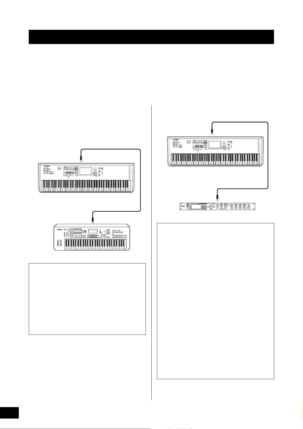
Connecting External MIDI Instruments
MIDI [IN ]
MIDI [OUT ]
MODX
External MIDI keyboard, synthesizer, etc.
External MIDI tone generator such as MOTIF-RACK XS
With a standard MIDI cable (commercially available), you can connect an external MIDI instrument, and control it from the
MODX. Likewise, you can use an external MIDI device (such as a keyboard or sequencer) to control the sounds on the MODX.
Below are several different MIDI connection examples; use the one most similar to your intended setup.
NOTE
Either of the built-in interfaces, the MIDI terminals, or the [USB TO HOST] terminal, can be used for MIDI data transmission/reception; however,
they cannot be used at the same time. Select which terminal is to be used for MIDI data transfer by pressing the [UTILITY] button [Settings]
tab [MIDI I/O] tab. As you work through the explanations in this chapter, set “MIDI IN/OUT” to “MIDI” since MIDI is used as the example
connection here.
Controlling the MODX from an external MIDI keyboard or synthesizer
Use an external keyboard or synthesizer to remotely select
and play the Performances of the MODX.
MIDI Transmit and Receive Channels
Make sure to match the MIDI Transmit Channel of the
external MIDI instrument with the MIDI Receive Channel of
the MODX. For details on setting the MIDI Transmit
Channel of the external MIDI instrument, refer to the
owner’s manual of that instrument. When the MIDI I/O
mode is set to “multi,” each MIDI Receive Channel number
of the MODX corresponds to an individual Part number,
such as Channel 1 for Part 1, Channel 2 for Part 2, and so
on. When the MIDI I/O is set to “single,” a single channel is
used for receiving all Parts.
Controlling an external MIDI keyboard or synthesizer from the MODX
This connection lets you sound an external MIDI tone
generator (synthesizer, tone generator module, etc.) by
playing the MODX or playing back Songs from the MODX.
Use this connection when you wish to sound the other
instrument as well as the MODX.
MIDI [OUT]
MODX
MIDI [IN]
Splitting the sound between the MODX and
an external tone generator by MIDI channel
Using the connection example shown above, you can play
both instruments and have them separately sound different
parts—for example, having your keyboard performance
sound the external instrument while the Song plays the
sounds of the MODX. To use this feature, you must set the
MODX’s transmit channel and the external tone generator’s
receive channel to the same channel number. Each MIDI
transmit channel number of the MODX corresponds to
each Part number such as Channel 1 for Part 1 or Channel
2 for Part 2. However, you can choose the desired transmit
channel by the following steps.
Press [UTILITY] [Settings] [Advanced], then set
“Zone Master” to “ON.” For editing the Part, touch [Part
Settings] [Zone Settings] to call up the Zone setting
display. Check the MIDI transmit channel in “Zone
Transmit,” then change this parameter, if necessary. When
you wish to sound only the external tone generator, set the
master volume of the MODX down or set “Local Control” to
“off” with the following operation: [UTILITY] [Settings]
[MIDI I/O] to call up the MIDI setting display, then set
“Local Control” to “off.” For information on how to set the
MIDI Receive Channel of the external MIDI instrument,
refer to the owner’s manual of that particular MIDI
instrument.
MODX Owner’s Manual
54
Page 59
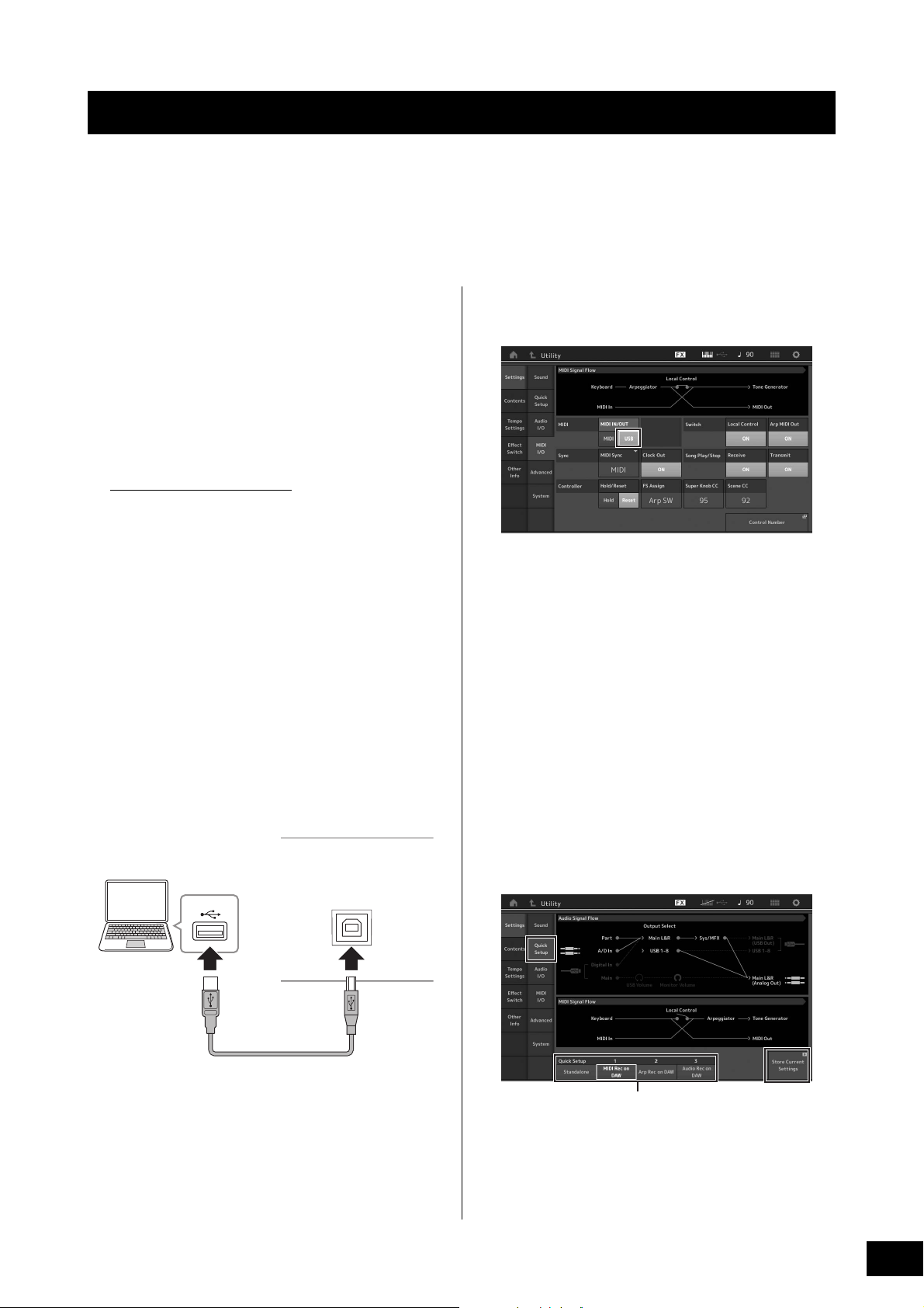
Using a Connected Computer
USB terminal
[USB TO HOST] terminal
USB cable
Rear panel
Quick Setups 1 to 3
By connecting the MODX to your computer, you can use a DAW or sequence software on the computer to create your own
original songs.
NOTE
The acronym DAW (digital audio workstation) refers to music software for recording, editing and mixing audio and MIDI data. The main DAW
applications are Steinberg Cubase, Ableton Live, and Apple Logic.
Connecting to a computer
A USB cable and the Yamaha Steinberg USB Driver are
necessary to connect the MODX to the computer. Follow the
instructions below. Note that both audio data and MIDI data
can be transmitted through a USB cable.
1 Download the latest Yamaha Steinberg USB
Driver from our website.
After clicking the Download button, extract the
compressed file.
https://download.yamaha.com/
After accessing the Support website (and clicking on
“Firmware/Software”), enter the appropriate model name.
NOTE
• Information on system requirements is also available at the
above website.
• The Yamaha Steinberg USB Driver may be revised and
updated without prior notice. Make sure to check and download the latest version from the above site.
2 Install the Yamaha Steinberg USB Driver to
the computer.
For instructions on installing, refer to the online
Installation Guide included in the downloaded file
package. When connecting this instrument to a
computer, connect the USB cable to the [USB TO HOST]
terminal of this instrument and the USB terminal of the
computer as shown below.
5 Set “MIDI IN/OUT” to “USB.”
Make sure that the [USB TO HOST] terminal of this
instrument is enabled.
6 Set the input and output settings for audio
data as desired to suit your personal
preferences.
The change can be made from [UTILITY] [Settings]
[Audio I/O].
Using the Quick Setup function to change parameters
related to audio and MIDI data, lets you instantly
reconfigure the MODX for different computer/sequencer
related applications by simply calling up specially
programmed presets.
To do this, touch [Settings] tab [Quick Setup] tab at
the left side of the display to call up the Quick Setup
display.
Touch [Store Current Settings] to store the desired
setting in any of the 1 to 3 Quick Setups.
NOTE
For details on the parameters available for setting with the Quick
Setup function, see the Reference Manual PDF document.
3 Press the [UTILITY] button to call up the
Utility display.
4 Touch [Settings] tab [MIDI I/O] tab at the
left side of the display.
MODX Owner’s Manual
55
Page 60

Using a Connected Computer
Precautions when using the [USB TO HOST]
terminal
When connecting the computer to the [USB TO HOST]
terminal, make sure to observe the following points to
avoid freezing the computer and corrupting or losing the
data.
NOTICE
• Use an AB type USB cable. USB 3.0 cables cannot be
used.
• Execute the following before turning the power to the
instrument on/off or plugging/unplugging the USB cable
to/from the [USB TO HOST] terminal.
-Quit any open application software on the computer.
-Make sure that data is not being transmitted from the
instrument. (Data is transmitted only by playing notes
on the keyboard or playing back a song.)
• While the computer is connected to the instrument, you
should wait for six seconds or more between these
operations: (1) when turning the power of the instrument
off then on again, or (2) when alternately connecting/
disconnecting the USB cable.
If the computer or the instrument freezes, restart the
application software or the computer OS, or turn the power
to the instrument off then on again.
Audio channels
The audio signals of the MODX can be output to the [USB
TO HOST] terminal and the OUTPUT [L/MONO]/[R] jacks.
When connecting to a computer, use the [USB TO HOST]
terminal. In this case, up to 10 audio channels (5 stereo
channels) are available. The output-to-channel
assignments are made as follows: [EDIT] [Part Settings]
“Part Output” in the [General] display.
The audio signals of the MODX can be input from the [USB
TO HOST] terminal and the A/D INPUT [L/MONO]/[R]
jacks.
Up to four channels (two stereo channels) of audio can be
input to the [USB TO HOST] terminal. Set the output level
in the Mixing display or the Performance edit display. The
signals are output to the OUTPUT [L/MONO]/[R] jacks (two
channels.) Also, up to two audio channels (one stereo
channel) can be input to the A/D INPUT [L/MONO]/[R]
jacks. The signal is sent to the A/D input part of the MODX.
For more details, see the Reference Manual PDF
document.
MIDI channels and MIDI ports
MIDI data is assigned to one of sixteen channels, and this
synthesizer is capable of simultaneously playing sixteen
separate Parts, via the sixteen MIDI channels. However,
the sixteen-channel limit can be overcome by using
separate MIDI “ports,” each supporting sixteen channels.
While a single MIDI cable is equipped to handle data over
up to sixteen channels simultaneously, a USB connection
is capable of handling far more—thanks to the use of MIDI
ports. Each MIDI port can handle sixteen channels, and
the USB connection allows up to eight ports, letting you
use up to 128 channels (8 ports x 16 channels) on your
computer.
When connecting this instrument to a computer using a
USB cable, the MIDI ports are defined as follows:
Port 1
The tone generator block in this instrument can recognize
and use only this port. When playing the MODX as a tone
generator from the external MIDI instrument or computer,
you should set the MIDI Port to 1 on the connected MIDI
device or computer.
Port 3
This port is used as the MIDI Thru Port. The MIDI data
received over Port 3 via the [USB TO HOST] terminal will
be re-transmitted to an external MIDI device via the MIDI
[OUT] terminal.
MODX Owner’s Manual
56
The MIDI data received over Port 3 via the MIDI [IN]
terminal will be re-transmitted to an external device
(computer, etc.) via the [USB TO HOST] terminal. When
using a USB connection, make sure to match the MIDI
transmit port and the MIDI receive port as well as the MIDI
transmit channel and the MIDI receive channel. Make sure
to set the MIDI port of the external device connected to this
instrument according to the above information.
Page 61

Using a Connected Computer
MODX
[USB TO HOST] terminal
Tone generator block
(recognizing data
over MIDI Channel 3)
Keyboard
(output via MIDI
Channel 1)
Local Control = off
Computer
(Cubase, etc.)
MIDI Thru = on
IN
CH1
OUT
CH3
Creating a Song with a computer
By using the MODX with DAW software on a computer
connected to the MODX, you can take advantage of the
following functions and applications.
• MIDI recording and audio recording of your MODX
performance to the DAW software.
• Playing back a song from the DAW software by using the
MODX tone generator.
This section contains an overview on how to use DAW
software on the computer with the MODX after connecting
(page 55).
Recording your performance on the
MODX to computer as MIDI data (no
Arpeggio playback recorded)
In this method, you record your performance on the MODX
to DAW simply as MIDI data. Keep in mind that Arpeggio
playback cannot be recorded.
Setting up the MODX
1 Press the [UTILITY] button to call up the
Utility display.
2 Touch [Settings] tab [Quick Setup] tab at
the left side of the display to call up the Quick
Setup display.
sound the MIDI data generated by playing the keyboard
as MIDI data from channel 3.
2 Record your MODX performance on the DAW
software.
Recording your performance on the
MODX to computer as MIDI data (with
Arpeggio playback recorded)
In this method you can record Arpeggio playback on the
MODX to DAW as MIDI data.
Setting up the MODX
3 Select “1 (MIDI Rec on DAW)” of “Quick
4 Press the [EXIT] button to select the
Setting up the DAW software
1 Set MIDI Thru to “on” on the DAW software.
Setup.”
Performance you want to record.
By setting MIDI Thru to “on,” the MIDI data generated by
playing the keyboard and transmitted to the computer
will be returned back to the MODX. As shown in the
example below, the MIDI data transmitted from the
MODX then recorded to the computer via MIDI channel 1
will be returned back from the computer to the MODX via
MIDI channel 3 according to the setting of the recording
Track. As a result, the tone generator of the MODX will
1 Press the [UTILITY] button to call up the
Utility display.
2 Touch [Settings] tab [Quick Setup] tab at
the left side of the display to call up the Quick
Setup display.
3 Select “2 (Arp Rec on DAW)” of “Quick
Setup.”
4 Press the [EXIT] button to select the
Performance you want to record.
Setting up the DAW software
Follow the same operations in “Recording your performance
on the MODX to computer as MIDI data (no Arpeggio
playback recorded).”
MODX Owner’s Manual
57
Page 62

Using a Connected Computer
Song playback from a computer using
the MODX as a tone generator
The instructions below show how to use this instrument as a
MIDI tone generator. In this case, actual MIDI sequence data
is transmitted from DAW software on the computer, letting
you take advantage of the dynamic sounds of the MODX,
while giving you the added benefit of saving processing
power on your computer by avoiding the use of software
synths.
Setting up the MODX
1 Select the Performance to be edited.
2 Touch the [Mixing] tab on the Performance
Play display to call up the Mixing display.
3 Set up the Mixing for Parts 1–16 as
necessary.
Setting up the DAW software
1 Set the MIDI output port of the Tracks for
playing the MODX to Port 1 of the MODX.
2 Enter the MIDI data to each Track of the DAW
software on the computer.
The tone generator settings of the part corresponding to
the MIDI Track will be set in the Mixing display on the
MODX.
MODX Owner’s Manual
58
Page 63

MEMO
MODX Owner’s Manual
59
Page 64

Saving/Loading Data
Select Content type
12
3
4
12
3
The Utility display provides tools for transferring the entire system setting and data (such as Performances and Live Sets)
between the MODX and a USB flash drive connected to the [USB TO DEVICE] terminal.
This section explains how to save/load all the data on the user memory of this instrument as a “User” file.
Saving the settings to a USB flash drive
1 Connect a USB flash drive to the [USB TO
DEVICE] terminal of this instrument.
2 Press the [UTILITY] button to call up the
Utility display, and then touch the [Contents]
tab [Store/Save] tab in the left of the
display.
3 Set “Content Type” to “User File.”
4 Select the desired directory of the USB flash
drive.
6 The Text input display appears. Input the file
name to be stored.
For detailed instructions on entering a name, see
“Naming (inputting characters)” in “Basic Operation and
Displays” (page 21).
7 Touch [Done] on the Text input display to
actually execute the Store operation.
NOTE
To overwrite the existing file, select “YES” on the display which
prompts you for confirmation.
Loading the settings from a USB flash drive
NOTICE
The Load operation overwrites the existing data in this
instrument. Important data should always be saved to a USB
flash drive connected to the [USB TO DEVICE] terminal.
1 Connect a USB flash drive to the [USB TO
DEVICE] terminal of this instrument.
2 Press the [UTILITY] button to call up the
Utility display, and then touch [Contents] tab
[Load] tab at the left side of the display.
3 Set “Content Type” to “User File.”
1 Parent folder
2 Store-destination folder in the USB flash drive
3 New store destination
4 Existing files
5 Touch “+” in [Save As New File].
NOTE
To overwrite the existing file, touch the file name.
4 Select the desired folder of the USB flash
drive.
5 Select the file (extension: .X8U) of the
memory to execute the Load operation.
1 Source USB flash drive
2 Source folder in the USB flash drive
3 Existing files
MODX Owner’s Manual
60
Page 65

Saving/Loading Data
Precautions when using the [USB TO DEVICE] terminal
This instrument features a built-in [USB TO DEVICE]
terminal. When connecting a USB device to the terminal, be
sure to handle the USB device with care. Follow the
important precautions below.
NOTE
For more information about the handling of USB devices, refer to the
owner's manual of the USB device.
Compatible USB devices
• USB flash drive
Other USB devices such as a USB hub, computer keyboard
or mouse cannot be used.
The instrument does not necessarily support all
commercially available USB devices. Yamaha cannot
guarantee operation of USB devices that you purchase.
Before purchasing a USB device for use with this instrument,
please visit the following web page:
https://download.yamaha.com/
After accessing the Support website (and clicking on
“Documents and Data”), enter the appropriate model name.
Although USB devices 1.1 to 3.0 can be used on this
instrument, the amount of time for saving to or loading from
the USB device may differ depending on the type of data or
the status of the instrument.
NOTICE
The rating of the USB TO DEVICE terminal is a maximum of 5V/
500mA. Do not connect USB devices having a rating above this,
since this can cause damage to the instrument itself.
Connecting a USB device
When connecting a USB device to the [USB TO DEVICE]
terminal, make sure that the connector on the device is
appropriate and that it is connected in the proper direction.
NOTICE
• Avoid connecting or disconnecting the USB device during
playback/recording and file management operations (such as
Save, Copy, Delete and Format), or when accessing the USB
device. Failure to observe this may result in “freezing” of the
operation of the instrument or corruption of the USB device
and the data.
• When connecting then disconnecting the USB device (and
vice versa), make sure to wait a few seconds between the two
operations.
Using USB flash drives
By connecting the instrument to a USB flash drive, you can
save data you’ve created to the connected device, as well
as read data from the connected device.
Maximum number of USB flash drives that
can be used
Only one USB flash drive can be connected to the [USB TO
DEVICE] terminal.
Formatting USB flash drive
You should format the USB flash drive only with this
instrument (page 61). A USB flash drive formatted on
another device may not operate properly.
NOTICE
The format operation overwrites any previously existing data.
Make sure that the USB flash drive you are formatting does not
contain important data.
NOTE
For details on how to format the USB flash drive, see the Reference
Manual PDF document.
To protect your data (write-protect)
To prevent important data from being inadvertently erased,
apply the write-protect provided with each USB flash drive. If
you are saving data to the USB flash drive, make sure to
disable write-protect.
Turning off the instrument
When turning off the instrument, make sure that the
instrument is NOT accessing the USB flash drive by
playback/recording or file management (such as during
Save, Copy, Delete and Format operations). Failure to do so
may corrupt the USB flash drive and the data.
MODX Owner’s Manual
61
Page 66

Shift Function List
Some of the important functions and operations on the instrument can be executed with convenient panel control shortcuts.
Simply hold down the [SHIFT] button and press the indicated button (as described below).
Operation Function
[SHIFT] + KNOB POSITION [1] Stores Assign 1–8 assigned to Knobs in Value 1.
[SHIFT] + KNOB POSITION [2] Stores Assign 1–8 assigned to Knobs in Value 2.
[SHIFT] + OCTAVE [-] Decreases the transpose value by 1.
[SHIFT] + OCTAVE [+] Increases the transpose value by 1.
[SHIFT] + OCTAVE [-] + OCTAVE [+] Resets the transpose value to 0.
[SHIFT] + [DEC/NO] Decreases the selected parameter value by 10.
In the Live Set display, this operation calls up the previous page.
[SHIFT] + [INC/YES] Increases the selected parameter value by 10.
In the Live Set display, this operation calls up the next page.
[SHIFT] + [ENTER] Calls up the Tempo Settings display.
[SHIFT] + [PERFORMANCE (HOME)] Calls up the Overview display.
[SHIFT] + [LIVE SET] Calls up the Live Set Register display.
[SHIFT] + [UTILITY] Calls up the Quick Setup display.
[SHIFT] + [CATEGORY] Calls up the Part Category Search display for the currently selected Part.
[SHIFT] + Slider Select [1–4] [5–8] Selects Part 9 or Part 13 when the Slider Function [PART]/[ELEMENT/OPERATOR]
button is set to “PART.”
[SHIFT] + [EDIT] Opens the Copy/Exchange dialog.
[SHIFT] + SCENE [1]–[8] Stores SCENE 1–8 in SCENE [1]–[8] buttons.
[UTILITY] + [PART SELECT MUTE/SOLO] Calls up the Touch Panel Calibration Setting display.
MODX Owner’s Manual
62
Page 67
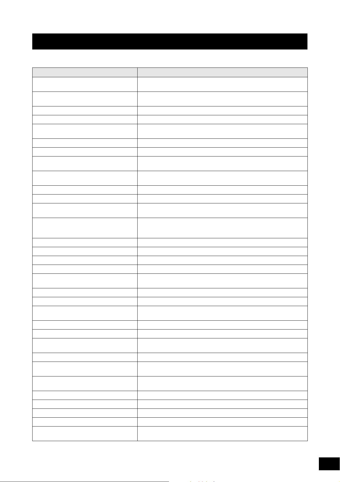
Display Messages
LCD indication Description
** will be deleted. This message appears when the specified operation you are about to execute will
** will be overwritten. This message appears when a file/folder having the same name as the one you
Activate the source controller to assign. You can assign the parameter to the controller you are about to activate.
Advanced settings will be initialized. All settings executed in [Advanced] tab will be initialized.
All data and libraries will be initialized. Unsaved
user data will be lost.
All data is initialized upon power-on. All data is initialized upon power-on.
All settings will be initialized. User data is kept. All settings will be initialized. User data is kept.
All sound will be stopped during optimization. This message appears before the internal memory is restored. All sound will be
All user data wil l be initialized. Unsaved user data
will be lost.
Are you sure? Confirms whether you want to execute a specified operation or not.
Arpeggio full. Appears when there are no more Arpeggio Part Switches to turn ON.
Assignable Knob Full. Appears when all of the Assignable Knobs are in use and no more Super Knob
Audio Rec stopped due to lack of memory space. The USB flash drive is full and no more audio recording data can be saved. Use a
Auto power off disabled. This message appears before Auto Power Off is disabled.
Bulk data protected. Bulk data cannot be received because of the setting.
Can’t process. The MODX cannot process a requested operation.
Completed. The specified load, save, format, or other Job has been completed.
Connecting to USB device... Currently recognizing the USB flash drive connected to the [USB TO DEVICE]
Control Assign Full. All Control Assigns are in use.
Copy protected. You have attempted to export or save a copy-protected digital audio source.
Current user data will be overwritten by **. This message appears when saving a file, and user data under that name already
Data memory full. The internal memory is full, preventing storing of the recorded data in the Library.
Device number is off. Bulk data cannot be transmitted/received since the device number is off.
Device number mismatch. Bulk data cannot be transmitted/received since the device numbers do not
File is not found. The specified file was not found during a Load operation.
File or folder already exists. A file/folder having the same name as the one you are about to save already
File or folder path is too long. The file or folder you tried to access cannot be accessed because the maximum
Folder is not empty. You have attempted to delete a folder that contains data.
Illegal bulk data. An error occurred while receiving a Bulk data or Bulk Request message.
Illegal file name. The specified file name is invalid. Try entering a different name.
Illegal file. The specified file is unusable by this synthesizer or cannot be loaded.
Keybank full. The maximum overall number of Key Banks has been exceeded when executing
cause the specified data to be deleted.
are about to save already exists.
All data and libraries will be initialized. Unsaved user data will be lost.
stopped during the optimization.
All user data will be initialized. Unsaved user data will be lost.
settings can be added.
new USB flash drive, or make space by erasing unwanted data from the USB
flash drive.
terminal.
exists.
match.
exists.
amount of characters indicating the path has been exceeded.
a Load operation.
MODX Owner’s Manual
63
Page 68

Display Messages
LCD indication Description
Library full. The maximum overall number of Libraries has been exceeded when executing
MIDI buffer full. Failed to process the MIDI data because too much data was received at one time.
MIDI checksum error. An error occurred when receiving bulk data.
Modified: Common AsgnKnob? Appears when the Control Assign settings for Common/Audio Edit are
No data. This message appears when the selected track or range contains no data. Select
No read/write authority to the file. Indicates that you do not have the authority to read/write the file.
Now initializing all data… Indicates this synthesizer is restoring the factory-programmed settings.
Now initializing… Indicates that the specified data is being initialized.
Now loading... Indicates that a file is being loaded.
Now receiving MIDI bulk data... Indicates this synthesizer is receiving MIDI bulk data.
Now saving... Indicates that a file is being saved.
Now transmitting MIDI bulk data... Indicates this synthesizer is transmitting MIDI bulk data.
Part Full. All Parts are in use.
Please connect USB device. Connect the USB device to the [USB TO DEVICE] terminal for audio recording.
Please keep power on. The data is being written to Flash ROM. Never attempt to turn off the power while
Please reboot to enable the new Audio I/O Mode. Please reboot this synthesizer to activate the change of the input/output settings
Please reboot to maintain internal memory. Please reboot this synthesizer to restore the internal memory.
Please stop audio play/rec. The operation you have attempted to execute cannot be done during audio
Please stop sequencer. The operation you have attempted to execute cannot be done during Song
Please wait… Indicates this synthesizer is executing the specified operation.
Recall latest edits. If you are editing a Performance and select a different Performance without
Redo last recording. Confirms whether you want to redo the operation you have undone.
Sample is protected. The sample data cannot be overwritten.
Sample is too long. The Sample size is too large and the Load operation cannot be executed.
Sample memory full. The Sample memory is full and further Load operations cannot be executed.
Scene stored. The Scene has been stored to one of the [SCENE] buttons.
Song data overload. The Song size is too large for playback.
Song full. The maximum overall number of Songs has been exceeded when executing the
Touch the white square. This message appears when you need to touch the displayed white rectangle
Turn on Memory Switch to memorize ** into this
scene.
Undo last recording. Confirms whether you want to undo the most recent recording.
Unsupported USB device. This message appears when an unsupported USB device has been connected.
USB connection terminated. A break in the connection with the USB flash drive has occurred because of an
the related operations.
automatically added or modified when you add or modify the settings for the
Assignable knobs that are associated to the Super Knob in the Control Assign
display for the Part Edit.
an appropriate track or range.
data is being written to Flash ROM. Turning the power off while this message is
shown results in loss of all user data and may cause the system to freeze (due to
corruption of data in the Flash ROM). This may also result in the MODX being
unable to properly start up the next time the power is turned on.
for audio data.
recording or playback.
playback.
storing your edited one, all the edits you’ve made will be erased. If this happens,
you can use Recall to restore the Performance with your latest edits intact.
related operations.
during touch panel calibration.
When the [Memory] (Memory Switch) is turned on for the function, the
corresponding function information is automatically stored in the currently
selected [SCENE] button.
abnormal electric current. Disconnect the USB flash drive from the [USB TO
DEVICE] terminal, and then press any of the panel buttons.
MODX Owner’s Manual
64
Page 69

Display Messages
LCD indication Description
USB device is full. The USB flash drive is full and no more data can be saved. Use a new USB flash
USB device is write-protected. This message appears when you have attempted to write to a protected USB
USB device read/write error. An error occurred while reading or writing to/from a USB flash drive.
USB device will be formatted. This message appears before the USB device is formatted.
Waveform full. The maximum overall number of Waveforms has been exceeded when executing
drive, or make space by erasing unwanted data from the storage device.
flash drive.
the related operations.
MODX Owner’s Manual
65
Page 70

Troubleshooting
No sound? Wrong sound? When a problem like this occurs, please check the following points before assuming that the product
is faulty. Many problems can be solved by executing Data Initialization (page 19), after backing up your data to a USB flash
drive (page 60). If the problem persists, consult your Yamaha dealer.
Touch panel does not respond correctly.
Is the point you touch on the touch panel lined up properly with the target item in the display underneath?
Calibrate the touch panel.
[UTILITY] + [PART SELECT MUTE/SOLO] [ENTER]
[UTILITY] [Settings] [System] [Calibrate Touch Panel]
No Sound.
Are all sliders set to appropriate levels (other than zero or minimum)?
Is the MODX properly connected to related external equipment (e.g., amplifier, speaker, headphones) via audio cables?
Since the MODX has no built-in speakers, you will need an external audio system or a set of stereo headphones to properly
monitor it (page 18).
Is the power of this synthesizer and any external equipment connected to this synthesizer turned on?
Have you made all the appropriate level settings—including the Master Volume on this synthesizer and the volume settings on
any connected external equipment?
When the Foot Controller is connected to the [FOOT CONTROLLER] jack, press the Foot Controller down.
Is the Local Control parameter set to off?
When the Local Control parameter is set to off, no sound is produced even if you play the keyboard.
[UTILITY] [Settings] [MIDI I/O] “Local Control”
Is a blank Part selected?
If so, assign any sound to the Part or select another Part.
Is the Mute switch for each Part turned on?
When the Mute switch is turned on, no sound is produced even if you play the keyboard.
[PERFORMANCE (HOME)] Part “Mute”
[PART SELECT MUTE/SOLO] “Mute” Part selection
Is the Keyboard Control of each Part turned off?
[PERFORMANCE (HOME)] Part “Kbd Ctrl”
Is the “Arp Play Only” parameter of each Part turned on?
When this parameter is turned on, the corresponding Part produces sound only via Arpeggio playback.
[PERFORMANCE (HOME)] Part selection [EDIT] [Part Settings] [General] “Arp Play Only”
[PERFORMANCE (HOME)] Part selection [EDIT] [Arpeggio] [Common] “Arp Play Only”
Are the MIDI volume or MIDI expression settings too low when using the external controller?
Are the effect and filter settings appropriate?
If you are using a filter, try changing the cutoff frequency. Some cutoff settings may filter out all of the sound.
[PERFORMANCE (HOME)] [EDIT] [Effect]
[PERFORMANCE (HOME)] Part selection [EDIT] [Effect]
• In case of Normal Part (AWM2) and Drum Part
[PERFORMANCE (HOME)] Part selection [EDIT] Element/Key selection [Filter]
Is “Vocoder” selected as the Insertion Effect Type of the Part?
MODX Owner’s Manual
66
• In case of Normal Part (FM-X)
[PERFORMANCE (HOME)] Part selection [EDIT] Operator selection [Pitch/Filter]
If so, set the parameters related to the A/D INPUT [L/MONO]/[R] jacks to the appropriate values then play the keyboard while
inputting your voice into the microphone connected to the MODX. Check whether or not the A/D INPUT [GAIN] Knob on the
rear panel is set to the minimum position.
[EDIT] Part selection Element/Key/Operator [Common] [Effect] [Routing]
Page 71

Are the volume or expression settings too low?
[UTILITY] [Settings] [Sound] Tone Generator “Volume”
[EDIT] [General] “Volume”
[EDIT] Part selection Element/Key/Operator [Common] [Part Settings] [General] “Volume”
[EDIT] Part selection Element/Key/Operator [Common] [Part Settings] [General] “Dry Level”
• In case of Normal Part (AWM2) and Drum Part
[EDIT] Part selection Element/Key selection [Amplitude] [Level/Pan] “Level”
• In case of Normal Part (FM-X)
[EDIT] Part selection Operator selection [Level] “Level”
Are the parameter settings such as Element Switch, Note Limit, Velocity Limit, and Velocity Offset appropriate?
• In case of Normal Part (AWM2) and Drum Part
[EDIT] Part selection Element/Key/Operator [Common] [Part Settings] [General]
[EDIT] Part selection Element/Key selection [Osc/Tune]
• In case of Normal Part (FM-X)
[EDIT] Part selection Element/Key/Operator [Common] [Part Settings] [General]
Is the Mute switch for each Element/Operator of Part turned on?
[EDIT] Part selection Mute Switch of each Element/Operator
In case of Normal Part (FM-X), is the Carrier Level is set to “0”?
[EDIT] Part selection Operator selection [Level] “Level”
Troubleshooting
Is the output parameter of each Part turned off?
[EDIT] Part selection Element/Key/Operator [Common] [Part Settings] [General] “Part Output”
No sound from the A/D INPUT jacks.
Is the switch of the microphone turned on?
Check the microphone type. Make sure to use a dynamic microphone.
Is the cable between the microphone or audio equipment and this instrument properly connected?
Is the A/D INPUT [GAIN] knob turned to the minimum?
Is the A/D INPUT [ON/OFF] button turned on?
Check whether or not the connection status of the A/D INPUT [L/MONO]/[R] matches the “Mono/Stereo” parameter.
[EDIT] [Audio In] [Mixing] A/D In “Input Mode”
Check whether or not the “Mic/Line” parameter is set to the appropriate value.
When the output level of the connected equipment (such as a microphone) is low, set this parameter to “Mic.” When the
output level of the connected equipment (such as a synthesizer keyboard, CD player) is high, set this parameter to “Line.”
[UTILITY] [Settings] [Audio I/O] “A/D Input”
Are the volume settings of the A/D Input Part too low?
[EDIT] [Audio In] [Mixing] A/D In “Volume”
Are the effect settings appropriate?
[EDIT] [Audio In] [Routing]
Is the output setting of the A/D Input Part set appropriately?
[UTILITY] [Settings] [Audio I/O] Output
Check whether or not the Vocoder Effect is selected.
When Vocoder is selected as the Insertion Effect for the current Part, the audio signal input from the A/D INPUT [L/MONO]/[R]
jacks may not produce any sound depending on the parameter settings.
[EDIT] Part selection Element/Key/Operator [Common] [Effect] [Routing]
MODX Owner’s Manual
67
Page 72

Troubleshooting
Playback continues without stopping.
When the [ARP ON/OFF] button is turned on, press it so that the button is turned off.
When in the Song display, press the [J] (Stop) button.
When the effect sound such as Delay continues, check the effect setting or select the Performance again.
When the click sound continues, check the following parameter setting. Set this parameter to something other than “always,”
since this setting always plays back the click sound regardless of the sequencer status.
[UTILITY] [Tempo Settings] Click “Mode”
Distorted sound.
Are the effect settings appropriate?
Use of an effect at certain settings may produce distortion.
[EDIT] Part selection Element/Key/Operator [Common] [Effect]
Are the filter settings appropriate?
Excessively high filter resonance settings can cause distortion.
• In case of Normal Part (AWM2) and Drum Part
[EDIT] Part selection Element/Key selection [Filter]
• In case of Normal Part (FM-X)
[EDIT] Part selection Element/Key/Operator [Common] [Pitch/Filter]
Are any of the following volume parameters set so high that clipping is occurring?
[UTILITY] [Settings] [Sound] Tone Generator “Volume”
[UTILITY] [Settings] [Audio I/O] “Output”
[EDIT] [General] “Volume”
[EDIT] Part selection Element/Key/Operator [Common] [Part Settings] [General] “Volume”
• In case of Normal Part (AWM2) and Drum Part
[EDIT] Part selection Element/Key selection [Amplitude] [Level/Pan] “Level”
• In case of Normal Part (FM-X)
[EDIT] Part selection Operator selection [Level] “Level”
Sound is cut off.
Is the entire sound (via your keyboard playback and Song/Part/Arpeggio playback) exceeding the maximum polyphony (128
for AWM2 and 64 for FM-X) of the MODX?
Only one note sounds at a time.
When this situation occurs, the Mono/Poly parameter in the current mode is set to “mono.”
If you wish to play chords, set this parameter to “poly.”
[EDIT] Part selection Element/Key/Operator [Common] [Part Settings] [General] “Mono/Poly”
Pitch or intervals are wrong.
Is the Master Tune parameter of each Part set to a value other than “0”?
Is the Note Shift parameter of each Part set to a value other than “0”?
MODX Owner’s Manual
68
[UTILITY] [Settings] [Sound] Tone Generator “Tune”
• In case of Normal Part (AWM2) and Drum Part
[EDIT] Part selection Element/Key/Operator [Common] [Part Settings] [Pitch] “Note Shift”
[EDIT] Part selection Element/Key/Operator [Common] [Part Settings] [Pitch] “Detune”
• In case of Normal Part (FM-X)
[EDIT] Part selection Element/Key/Operator [Common] [Pitch/Filter] [Pitch] “Note Shift”
[EDIT] Part selection Element/Key/Operator [Common] [Pitch/Filter] [Pitch] “Detune”
Page 73

When the Part produces a wrong pitch, is the appropriate tuning system selected from the Micro Tuning parameter?
• In case of Normal Part (AWM2)
[EDIT] Part selection Element/Key/Operator [Common] [Part Settings] [Pitch] “Micro Tuning Name”
• In case of Normal Part (FM-X)
[EDIT] Part selection Element/Key/Operator [Common] [Pitch/Filter] [Pitch] “Micro Tuning Name”
When the Part produces a wrong pitch, is the LFO Pitch Modulation Depth set too high?
• In case of Normal Part (AWM2)
[EDIT] Part selection Element selection [Element LFO] “Pitch Mod”
• In case of Normal Part (FM-X)
[EDIT] Part selection Element/Key/Operator [Common] [Mod/Control] [2nd LFO] “Pitch Modulation”
When a Part produces a wrong pitch, are Coarse tune and Fine tune settings appropriate?
• In case of Normal Part (AWM2) and Drum Part
[EDIT] Part selection Element/Key selection [Osc/Tune] “Coarse”
[EDIT] Part selection Element/Key selection [Osc/Tune] “Fine”
• In case of Normal Part (FM-X)
[EDIT] Part selection Operator selection [Form/Freq] “Coarse”
[EDIT] Part selection Operator selection [Form/Freq] “Fine”
Troubleshooting
When the Part seems to produce the wrong pitch, is the destination of the controller set to “Pitch”?
[EDIT] Part selection [Mod/Control] [Control Assign] “Destination”
No effect is applied.
Is the Effect Switch turned off?
[UTILITY] [Effect Switch]
Is the Variation Send or Reverb Send set to a value other than “0”?
[EDIT] Part selection Element/Key/Operator [Common] [Effect] [Routing] “Var Send”
[EDIT] Part selection Element/Key/Operator [Common] [Effect] [Routing] “Rev Send”
Is the Variation Return or Reverb Return set to a value other than “0”?
[EDIT] [Effect] [Routing] “Var Return”
[EDIT] [Effect] [Routing] “Rev Return”
Have any or all of the Element/Keys’ Insertion Effect Output parameters been set to “thru” in the effect setting?
[EDIT] Part selection Element/Key/Operator [Common] [Effect] [Routing] “Element 1–8”
In case of System Effect, have any or all of the effect types been set to “No Effect”?
In case of Insertion Effect, have any or all of the effect types been set to “Thru”?
Check whether the Insertion Switch parameters are set properly or not.
[EDIT] Part selection Element/Key/Operator [Common] [Effect] [Ins A]/[Ins B]
Have you exceed the number of Parts for applying Insertion Effect?
For Parts 9 -16, you can apply Insertion Effects to up to 4 Parts.
[EDIT] Part selection Element/Key/Operator [Common] [Effect] [Ins Assign]
Cannot start the Arpeggio.
Check whether the [ARP ON/OFF] button is turned on or off.
Count the number of Parts whose Arpeggio switches are turned on.
You can play back the Arpeggios of up to eight Parts simultaneously.
Are the Arpeggio related parameters such as Note Limit and Velocity Limit set appropriately?
[EDIT] Part selection Element/Key/Operator [Common] [Arpeggio] [Common]
MODX Owner’s Manual
69
Page 74

Troubleshooting
Is the Arpeggio Type parameter set to “off”?
[EDIT] Part selection [Arpeggio] [Individual] “Name”
Check the Arpeggio Switch parameter.
If this parameter for the current Part is set to off, Arpeggio playback will not be triggered by your keyboard performance even
if the [ARP ON/OFF] button is turned on.
[PERFORMANCE (HOME)] Part selection “Arp On”
Is the [Arp Bypass] button set to “on”?
[UTILITY] [Effect Switch]
Cannot stop the Arpeggio.
When Arpeggio playback does not stop even if you release the key, set the Arpeggio Hold parameter to “off.”
[EDIT] Part selection Element/Key/Operator [Common] [Arpeggio] [Common] “Hold”
The Song cannot be started even when pressing the [R] (Play) button.
Does the selected Song actually contain data?
Song cannot be recorded.
Is there enough free memory for recording?
MODX memory can record up to 128 Songs. If the memory becomes full, no more recording is possible.
Data communication between the computer and the MODX does not work properly.
Check whether the Port settings on the computer are appropriate or not.
Check whether or not the MIDI IN/OUT parameter is set to the appropriate value.
[UTILITY] [Settings] [MIDI I/O] MIDI “MIDI IN/OUT”
MIDI bulk data transmission/reception does not work properly.
Is the Receive Bulk parameter set to off?
Set the Receive Bulk parameter to on.
[UTILITY] [Settings] [Advanced] MIDI “Receive Bulk”
When receiving MIDI bulk data transmitted via the Bulk Dump function and recorded to the external MIDI device, you need to
set the MIDI Device Number to the same value as when transmitting.
[UTILITY] [Settings] [Advanced] MIDI “Device Number”
When transmission does not work properly, is the device number of the MIDI instrument connected to the MODX set to match
the Device Number parameter?
[UTILITY] [Settings] [Advanced] MIDI “Device Number”
Cannot save data to the USB flash drive.
Is the USB flash drive being used write protected? (Write-protect should be set to off for saving data.)
Is there enough free space on the USB flash drive?
In the Contents display, set the device to the USB flash drive. Check the amount of currently available (unused) memory of the
USB flash drive indicated at the right top of the display.
[UTILITY] [Contents] [Load]/[Store/Save]
Is operation of the particular USB flash drive guaranteed by Yamaha?
In the display, there are some black points (unlit) or white points (always lit).
These are the result of defective pixels and occasionally occur in LCD; they do not indicate a problem in operation.
MODX Owner’s Manual
70
For details, see page 61.
Page 75

Specifications
Keyboards
To n e
Generator
block
Sequencer
block
Others
MODX8: 88 keys, GHS Keyboard (Initial Touch)
MODX7: 76 keys, Semi-weighted Keyboard (Initial Touch)
MODX6: 61 keys, Semi-weighted Keyboard (Initial Touch)
Tone Generator Motion Control Synthesis Engine
Polyphony AWM2: 128 (max.; stereo/mono waveforms)
Multi Timbral Capacity 16 Parts (internal), Audio Input Parts (A/D
Waveforms Preset: 5.67 GB (when converted to 16-bit linear format), User: 1.00 GB
Performances Approx. 2,000
Filters 18 types
Effect System Reverb x 12 types, Variation x 85 types, Insertion (A, B) x 85 types
Note Capacity Approx. 130,000 notes
Note Resolution 480 ppq (parts per quarter note)
Tempo (BPM) 5–300
Performance
Recorder
Sequence Format MODX original format, SMF formats 0, 1
Arpeggio Part 8 Parts simultaneous (max.)
Motion
Sequencer
Live Sets Preset: 256 and more, User: 2,048
Controllers Master Volume, AD Input Gain knob, USB Volume, Pitch Bend wheel, Modulation wheel,
Display 7" TFT Color Wide VGA LCD touch screen
Connectors [USB TO DEVICE], [USB TO HOST], MIDI [IN]/[OUT], FOOT CONTROLLER [1]/[2],
USB Audio
Interface
Power Consumption 16 W (when using PA-150B AC adaptor)
Dimensions, Weight MODX8: 1,333 (W) × 404 (D) × 160 (H) mm (52-1/2" x 15-7/8" x 6-1/16"), 13.8 kg (30 lbs 7 oz)
Accessories AC adaptor (PA-150B or an equivalent recommended by Yamaha*), Owner’s Manual (this book),
Songs 128 songs
Tracks 16 Sequence tracks, Tempo track, Scene track
Recording type Real time replace, Real time overdub, Real time punch in/out
Preset 10,239 types
User 256 types
Lane 8 + 1 Lanes (max.)
Sampling
Frequency
Channels In: 4 channels (2 stereo channels)
AWM2: 8 Elements
FM-X: 8 Operators, 88 Algorithms
FM-X: 64 (max.)
*1
*1 stereo Part
*2 A/D part insertion x 80 types
<Preset settings for parameters of each effect type are provided as templates>
Master EQ (5 bands), 1st part EQ (3 bands), 2nd part EQ (2 bands)
Control Sliders x 4, Knobs x 4, Super Knob, Data dial
FOOT SWITCH [ASSIGNABLE]/[SUSTAIN], OUTPUT [L/MONO]/[R] (6.3 mm, standard phone jacks),
[PHONES] (6.3 mm, standard stereo phone jack),
A/D INPUT [L/MONO]/[R] (6.3 mm, standard phone jacks)
44.1 kHz
Out: 10 channels (5 stereo channels)
MODX7: 1,144 (W) × 331 (D) × 134 (H) mm (45-1/16" x 13-1/16" x 5-1/4"), 7.4 kg (16 lbs 5 oz)
MODX6: 937 (W) × 331 (D) × 134 (H) mm (36-7/8" x 13-1/16" x 5-1/4"), 6.6 kg (14 lbs 9 oz)
Cubase AI Download Information
* May not be included depending on your area. Check with your Yamaha dealer.
, USB*1)
*2
, Master Effect x 23 types
* The contents of this manual apply to the latest specifications as of the publishing date. To obtain the latest manual, access the Yamaha website then
download the manual file. Since specifications, equipment or separately sold accessories may not be the same in every locale, please check with your
Yamaha dealer.
MODX Owner’s Manual
71
Page 76

GNU GENERAL PUBLIC LICENSE
GNU LESSER GENERAL PUBLIC LICENSE
Note on source code distribution
For three years after the final factory shipment, you may request from Yamaha the source code for any portions of the product which are licensed under the
GNU General Public License or GNU Lesser General Public License by writing to the following address:
DMI Marketing Group, DMI Division
Musical Instruments Business Division
YAMAHA Corporation
10-1 Nakazawa-cho, Naka-ku, Hamamatsu, 430-8650, JAPAN
The source code will be provided at no charge; however, we may require you to reimburse Yamaha for the cost of delivering the source code to you.
• Note that we shall bear no responsibility whatsoever for any damage arising from changes (additions/ deletions) made to the software for this product by
a third party other than Yamaha (or party authorized by Yamaha).
• Note that re-use of source code released to the public domain by Yamaha is unguaranteed, and Yamaha shall not bear any responsibility whatsoever for
the source code.
• The source code can be downloaded from the following address:
https://download.yamaha.com/sourcecodes/synth/
MODX Owner’s Manual
72
Page 77

Index
A
A/D INPUT [GAIN] knob ........................................................... 10
A/D INPUT [L/MONO]/[R] jacks................................................ 17
A/D INPUT [ON/OFF] button..................................................... 10
ABS (Audio Beat Sync)............................................................. 17
[ARP ON/OFF] (Arpeggio on/off) button................................... 11
Arpeggio ................................................................................... 28
Arpeggio type ........................................................................... 43
[ASSIGN 1] and [ASSIGN 2] buttons
(Assignable switches 1 and 2) ................................................. 10
[ASSIGN] button ....................................................................... 12
Audio channel........................................................................... 56
[AUDITION] button ................................................................... 15
Audition phrase......................................................................... 25
Auto Power Off.......................................................................... 19
C
Carrier ....................................................................................... 38
[CATEGORY] button ................................................................. 15
Category Search....................................................................... 24
Compare function ..................................................................... 40
[CONTROL ASSIGN] button ..................................................... 13
Control Sliders 1–4 (5–8/9–12/13–16) ....................................... 12
Controllers................................................................................. 29
Cursor buttons .................................................................... 14, 20
D
Data dial.................................................................................... 14
DAW (digital audio workstation) ............................................... 55
[DC IN]...................................................................................... 17
[DEC/NO] button....................................................................... 14
Display Messages .................................................................... 63
Drum Part.................................................................................. 22
E
[EDIT] button............................................................................. 14
Effect......................................................................................... 39
Element Common Edit .............................................................. 38
Element Edit.............................................................................. 38
[ENTER] button ......................................................................... 14
Envelope Follower............................................................... 17, 44
[EXIT] button ............................................................................. 14
F
Flag ........................................................................................... 23
FM ............................................................................................. 38
FOOT CONTROLLER [1]/[2] jacks ........................................... 17
FOOT SWITCH [ASSIGNABLE]/[SUSTAIN] jacks .................... 17
Formatting................................................................................. 61
Frequency modulation .............................................................. 38
G
GM ............................................................................................ 22
GM Bank ................................................................................... 22
H
Headphones..............................................................................18
I
[INC/YES] button ....................................................................... 14
Initial factory settings.................................................................19
Initialized Performance..............................................................25
Inputting on the keyboard ......................................................... 21
Inputting on the numeric keypad ..............................................21
K
Key Common Edit...................................................................... 38
Key Edit ..................................................................................... 38
Keyboard...................................................................................10
Knob Function [TONE]/[EG/FX]/[EQ]/[ARP/MS] button ............12
KNOB POSITION [1] and [2] buttons........................................13
Knobs ........................................................................................ 30
Knobs 1–4 (5–8) ........................................................................ 12
L
Layer ......................................................................................... 41
Library Bank .............................................................................. 22
Live Set................................................................................23, 35
[LIVE SET] button ...................................................................... 15
Live Set display ......................................................................... 20
Loading .....................................................................................60
Local Control ............................................................................. 53
M
Master Tuning............................................................................52
Master Volume........................................................................... 19
[MASTER VOLUME] knob ......................................................... 10
Microphone ...............................................................................50
MIDI [IN], [OUT] terminals......................................................... 17
MIDI channel ............................................................................. 56
MIDI port.................................................................................... 56
MIDI Receive Channel............................................................... 54
MIDI Recording ......................................................................... 45
MIDI Transmit Channel..............................................................54
Mixing........................................................................................33
Modulation wheel ......................................................................10
Modulator ..................................................................................38
[MOTION SEQ HOLD] (Motion Sequencer hold) button ...........11
[MOTION SEQ TRIGGER] (Motion Sequencer trigger) button.. 11
Motion Sequencer ..................................................................... 28
[MS ON/OFF] (Motion Sequencer on/off) button.......................11
Multi Part Performance ..............................................................22
Mute function.............................................................................27
N
Normal Part (AWM2).................................................................. 22
Normal Part (FM-X)....................................................................22
MODX Owner’s Manual
73
Page 78

Index
O
OCTAVE [-] and [+] buttons ..................................................... 11
Operator.................................................................................... 38
Operator Common Edit............................................................. 38
Operator Edit ............................................................................ 38
OUTPUT [L/MONO] and [R] jacks............................................ 17
P
Part Control status .................................................................... 30
Part Editing ............................................................................... 38
[PART SELECT MUTE/SOLO] button........................................ 15
Performance ............................................................................. 22
[PERFORMANCE (HOME)] button............................................ 14
Performance Control status ...................................................... 30
Performance Edit display.......................................................... 37
Performance Editing ................................................................. 37
Performance Play...................................................................... 26
Performance Play display ......................................................... 20
[PHONES] (Headphone) jack ................................................... 17
Pitch Bend wheel ...................................................................... 10
Power ........................................................................................ 18
Power-on tasks ......................................................................... 51
Preset Bank............................................................................... 22
Punch In/Out ............................................................................. 46
U
Undo..........................................................................................46
[USB TO DEVICE] terminal..................................................17, 61
[USB TO HOST] terminal.....................................................17, 56
[USB VOLUME (MONITOR)] knob ............................................10
User Bank..................................................................................22
[UTILITY] button ........................................................................ 14
Y
Yamaha Steinberg USB Driver ..................................................55
Z
Zone ..........................................................................................49
Q
Quick Setup .............................................................................. 55
R
Realtime Recording .................................................................. 45
Redo ......................................................................................... 46
Rhythm Part .............................................................................. 43
Rhythm Pattern ......................................................................... 43
[RHYTHM PATTERN] button..................................................... 13
S
Saving ....................................................................................... 60
SCENE [1/5] [2/6] [3/7] [4/8] buttons........................................ 12
Scene function .......................................................................... 34
Scene Select [1–4] [5–8] button ............................................... 12
SEQ TRANSPORT button.......................................................... 13
[SHIFT] button........................................................................... 14
Single Part Performance ........................................................... 22
Slider Function [PART]/[ELEMENT/OPERATOR] button........... 12
Slider Select [1–4] [5–8] button ................................................ 12
Solo function ............................................................................. 27
Song.................................................................................... 45, 47
Split ........................................................................................... 42
SSS (Seamless Sound Switching) ............................................ 23
[P] (Standby/On) switch .......................................................... 17
Store.......................................................................................... 37
[STORE] button......................................................................... 14
Super Knob......................................................................... 13, 31
T
Touch panel LCD...................................................................... 13
Track ......................................................................................... 45
MODX Owner’s Manual
74
Page 79

MEMO
75
Page 80

MEMO
76
Page 81

777879
Page 82

Page 83

Page 84

Manual Development Group
© 2018 Yamaha Corporation
Published 02/2018 MW TY*.*-**A0
ZY80660
80
 Loading...