

Page 1

SIGNAL PROCESSOR
Using the PDF manual
• From the Contents on page 2, click on the desired topic to automatically jump to the corresponding page.
• Click on a link
in this manual to jump to the corresponding page.
• If you want to find information on a specific topic, function or feature, select “Find” or “Search” from the Acrobat Reader
“Edit” menu and enter a key word to locate the related information anywhere in the document.
• You can also click on desired items and topics you want to refer to in the “Bookmarks” index to the left of the main
display window, and jump to the corresponding page. (Click the “Bookmarks” tab to open the index if it is not
displayed).
NOTE
The names and positions of menu items may vary according to the version of Acrobat Reader being used.
Operation Manual
EN
Page 2

1. Contents
2. Overview ...........................................................................................3
2-1. MMP1 Editor (for Windows/for Mac) ........................................................... 4
2-2. MMP1 Controller (for iPad).......................................................................... 4
3. Setting Up .........................................................................................5
3-1. Open the application ................................................................................... 5
3-2. Log in (MMP1 Editor only) ........................................................................... 5
3-3. Select an MMP1 .......................................................................................... 5
3-4. Configure basic settings .............................................................................. 6
4. Screens .............................................................................................7
4-1. MMP1 Editor................................................................................................ 7
4-2. MMP1 Controller ....................................................................................... 42
4-1-1. Menu bar .....................................................................................................7
4-1-2. Main screen.................................................................................................8
4-1-3. Sub screen ................................................................................................15
4-1-4. Monitor Matrix screen................................................................................18
4-1-5. Speaker Matrix screen ..............................................................................20
4-1-6. Speaker Management screen ...................................................................22
4-1-7. Patch screen .............................................................................................23
4-1-8. Settings screen..........................................................................................26
4-1-9. Information screen.....................................................................................40
4-2-1. Menu bar ...................................................................................................42
4-2-2. Control view...............................................................................................42
4-2-3. Editor view - Main Monitor screen .............................................................45
4-2-4. Editor view - Ch Strip screen.....................................................................47
4-2-5. Editor view - Preference screen ................................................................50
4-2-6. Information screen.....................................................................................51
5. Configuring System Settings........................................................52
5-1. Basic settings example.............................................................................. 52
5-2. Bass Management .................................................................................... 59
5-3. Lip Sync Delay .......................................................................................... 60
5-4. Commentary functions .............................................................................. 61
6. Appendix.........................................................................................64
6-1. Error messages ......................................................................................... 64
6-2. MMP1 Editor keyboard shortcuts .............................................................. 65
7. Index................................................................................................66
Information
• The illustrations and screens as shown in this manual are for instructional purposes only.
• Yamaha Corporation makes no representations or warranties with regard to the use of the software and
documentation and cannot be held responsible for the results of the use of this manual and the software.
• Windows is a registered trademark of Microsoft® Corporation in the United States and other countries.
• Mac and iPad are trademarks of Apple Inc., registered in the U.S. and other countries.
• The company names and product names in this manual are the trademarks or registered trademarks of
their respective companies.
• Software may be revised and updated without prior notice.
MMP1 Operation Manual 2
Page 3
2. Overview
FIR
IIR
Bass Management
Filter (32)
Monitor
Alignment
Process (32)
DAW
Mic Pre-amp
Surround
Speakers
Speaker
Processor
Headphone
(player)
Headphone
(engineer)
DAW
Outboard
(EQ, Compressor, etc.)
Output Patch
Output Patch
input Patch
Insert
Return
Insert Send
Channel
Strip (8)
Speaker Matrix
(32x32 Matrix Mixer)
Monitor Matrix
(40x36 Matrix Mixer)
Trim
Delay
EQ (6)
Speaker
Out
Monitor
Out
Cue Out
Headphone
Out
Channel Out
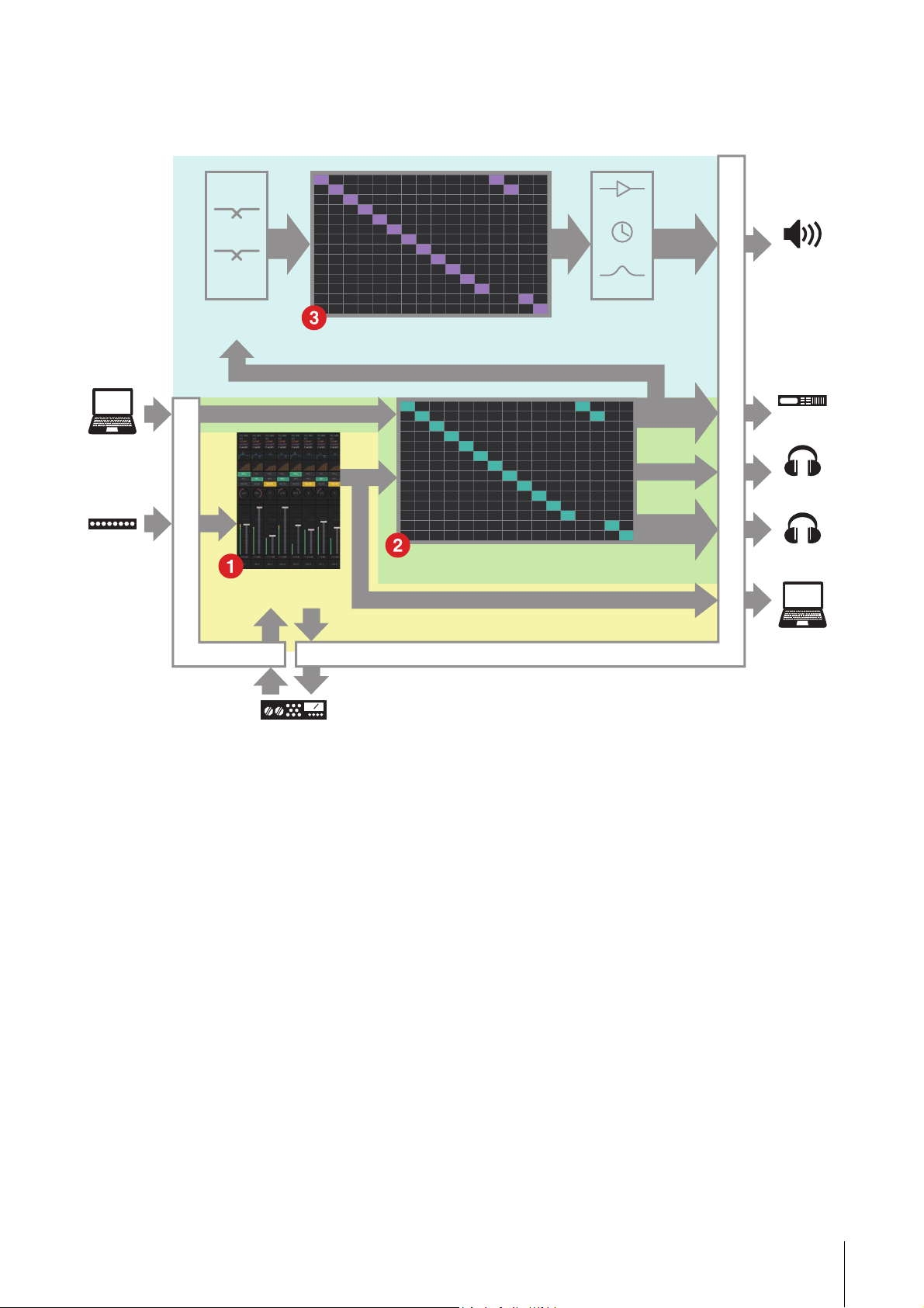
The MMP1 has three main functions.
2. Overview
1 Channel strip function
Allows for the use of up to eight channel strips, each equipped with HPF, LPF, EQ, compressor, insert send/return and
other functions. This can be used to input the signal from the microphone preamp to which the recording microphone is
connected and adjust sound quality when recording to produce a low-latency cue mix. The microphone on each
channel strip can also be turned on or off using a GPI, an iPad, or other similar device (see “5-4. Commentary
functions”).
2 Monitor processing function (max. 40x36 matrix)
This is used to select a Monitor Source, mix Monitor Sources, adjust levels, and control lip sync delay and cue mix
Talkback. You can also mix the output from channel strip (1) and the cue audio sent from the DAW to produce a lowlatency cue mix.
3 Speaker Management function (max. 32x32 matrix)
This adjusts monitor signals. The matrix input stage comes with a bass management crossover filter to allow for
unrestricted bass management not constrained by conventional 5.1 channel and 7.1 channel setups. This ensures
compatibility should new surround sound formats be introduced in the future.
The output stage comes equipped with 6-band EQ, delay and level adjustment trim controls, and can be used while
switching the output Speaker Set.
The following two applications can be used to operate the MMP1.
• MMP1 Editor (for Windows/for Mac)
• MMP1 Controller (for iPad)
MMP1 Operation Manual 3
Page 4
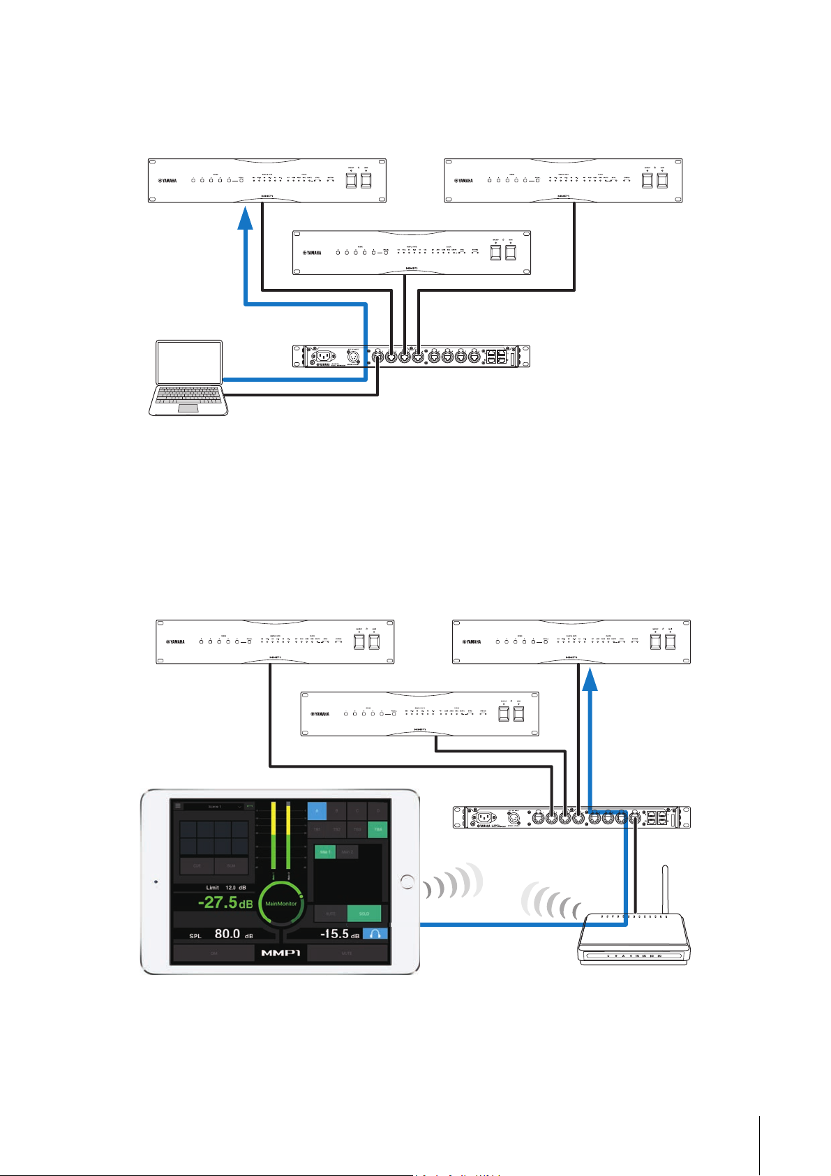
2-1. MMP1 Editor (for Windows/for Mac)
MMP1
MMP1MMP1
MMP1
Editor
Network switch
Computer
MMP1
MMP1MMP1
iPad
Network switch
Wi-Fi access point
Connect the MMP1 Editor to the MMP1 on your network (one unit) to control all MMP1 functions.
2. Overview
2-2. MMP1 Controller (for iPad)
Connect the MMP1 Controller to the MMP1 on your network (one unit) for convenience and ease in controlling certain MMP1
functions.
NOTE
Before using the MMP1 Controller, you will need to make initial settings to your MMP1 using the MMP1 Editor.
MMP1 Operation Manual 4
Page 5
3. Setting Up
3. Setting Up
3-1. Open the application
3-1-1. MMP1 Editor
Click or double click the MMP1 icon.
3-1-2. MMP1 Controller
Tap the MMP1 Controller icon.
3-2. Log in (MMP1 Editor only)
3-3. Select an MMP1
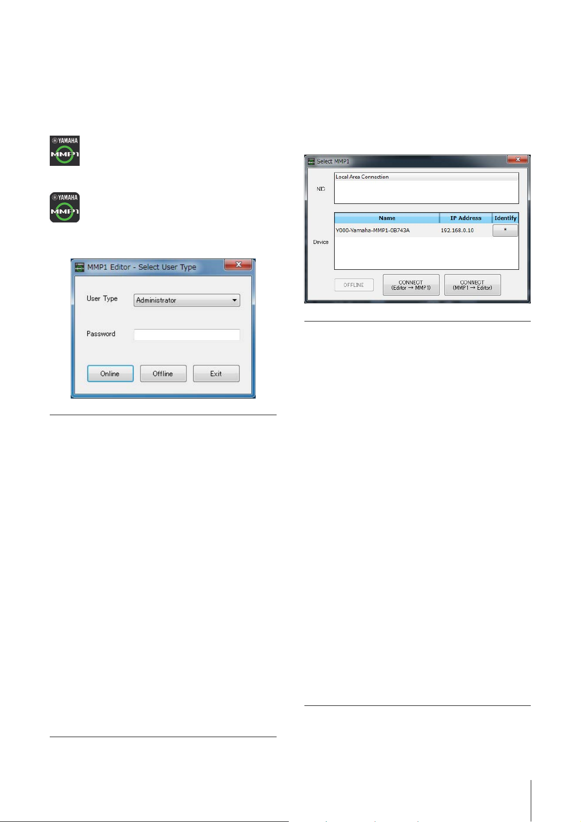
3-3-1. MMP1 Editor
Select an MMP1 on the “Select MMP1” dialog box.
NOTE
You can also display the “Select MMP1” dialog box from the
menu bar to change the desired MMP1 for operation at any time.
NIC
Select the network interface card
connected to the MMP1 to operate.
User Type
Password
Online
Offline
You can restrict the MMP1 Editor operations
according to their User Type. The following
three User Types are available.
Administrator
Allows unrestricted access to all screens
and functions.
Advanced User
Allows access to almost all functions
besides settings (Settings screen).
Basic User
Allows access only to the Main screen and
the Information screen.
Enter your password to log in as an
“Administrator” or “Advanced User.”
NOTE
• “Administrator” and “Advanced User”
passwords can be set on the “Editor” tab
of the Settings screen.
• Passwords are left blank by default when
unset.
Opens the “Select MMP1” dialog box for
selecting desired MMP1.
Edits the MMP1 Editor offline without
connection to or control of the MMP1.
Device
OFFLINE
CONNECT
(Editor MMP1)
CONNECT
(MMP1 Editor)
Select the MMP1 to operate. Click the
asterisk (*) in the Identify column so that the
indicator on the front panel of the
corresponding MMP1 flashes on and off.
Disconnects from the MMP1 and closes the
“Select MMP1” dialog box.
Connects to the MMP1 selected in the
Device field and sends MMP1 Editor
settings to the MMP1. The “Select MMP1”
dialog box will close after settings are sent.
NOTE
You must enter the Passcode for the MMP1
when connecting to an MMP1 with a
Passcode set. You can set Passcodes on
the Information screen when logged in as
an Administrator. Entering a passcode is
not necessary when connecting to the
same MMP1 as that used previously.
Connects to the MMP1 selected in the
Device field and loads MMP1 settings into
the MMP1 Editor. The “Select MMP1” dialog
box will close after settings are retrieved.
NOTE
You must enter the Passcode for the MMP1
when connecting to an MMP1 with a
Passcode set.
You can set Passcodes on the Information
screen when logged in as an Administrator.
Entering a passcode is not necessary when
connecting to the same MMP1 as that used
previously.
Exit
Closes the MMP1 Editor.
MMP1 Operation Manual 5
Page 6
3. Setting Up
1
3
2
Disconnecting from the MMP1
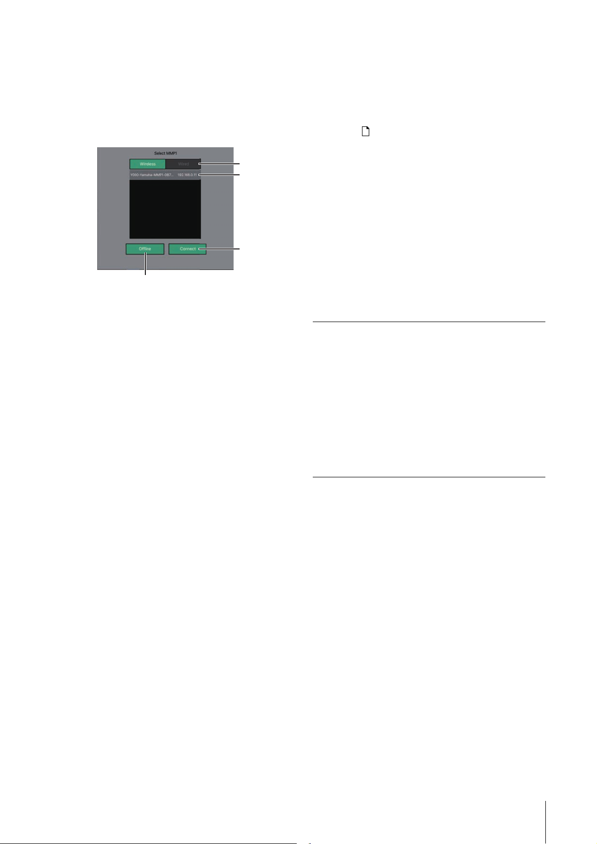
3-3-2. MMP1 Controller
Select an MMP1 on the “Select MMP1” dialog box. The
“Select MMP1” dialog box is displayed when launching
the MMP1 Controller.
NOTE
You can also display the “Select MMP1” dialog box from the
menu bar to change the desired MMP1 for operation at any time.
1 Select the MMP1 connection.
2 Tap to select the MMP1 to operate.
3 Tap to connect.
NOTE
• You can switch between Wireless/Wired on iOS 9.3 or later
devices.
• You must enter the Passcode for the MMP1 when connecting
to an MMP1 with a Passcode set. Entering a passcode is not
necessary when connecting to the same MMP1 as that used
previously.
3-4. Configure basic settings
NOTE
Only the MMP1 Editor can be used to configure basic settings.
Basic settings must be configured on the MMP1 Editor before the
MMP1 Controller can be used.
1. Select “ (file icon)” on the menu bar, then select
“New.”
2. Select whether or not you want to use the Setup
Wizard.
Next, follow the on-screen instructions.
When using the Setup Wizard, configure basic settings by
answering the questions as they appear on the screen.
Canceling the Setup Wizard before it is complete will
revert settings to what they were prior to launching the
Setup Wizard.
When the Setup Wizard is not used, the following values
will be applied automatically.
Sample Rate 48 kHz
Speaker Format Stereo
LFE Filter None
LFE Trim None
Bass Management None
Monitor Source None
Speaker Set None
Cue Mix Input Channel None
Cue Mix Output Channel None
Talkback Mic Input Channel None
MMP1 Operation Manual 6
Page 7
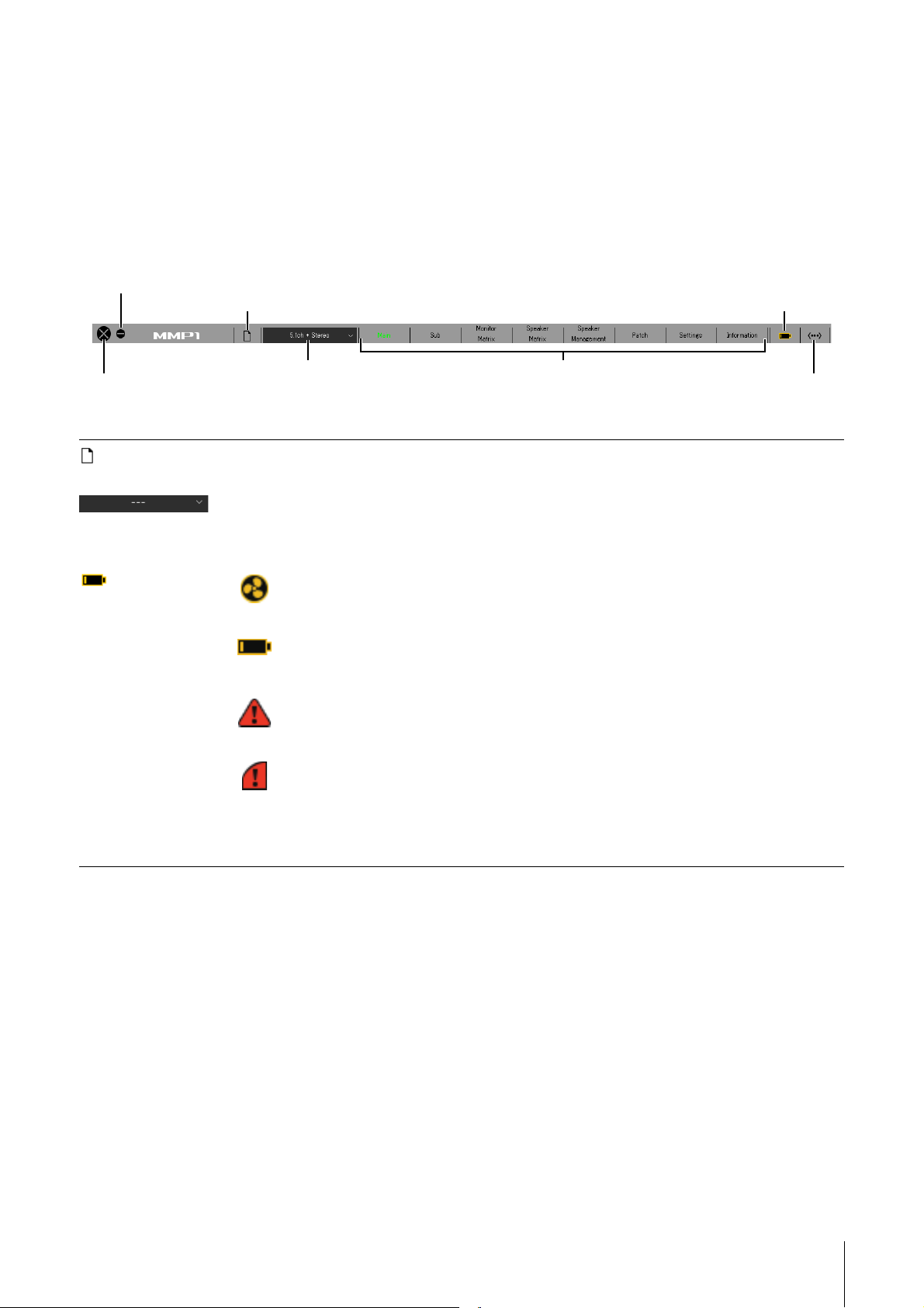
4. Screens
Closes the MMP1 Editor
Minimizes the MMP1 Editor
Creates and saves files
Selects a Scene
Switches screens
Displays errors
Displays online (green)/offline status
Click to display the “Select MMP1” dialog box
4-1. MMP1 Editor
4-1-1. Menu bar
This is a shared menu that appears on all screens.
4. Screens
(File icon) “Administrator” privileges are required to use files.
(Error icon) Cooling fan has stopped
When you open a file online, the settings in the opened file are sent to the connected MMP1.
Store different system configurations as Scenes to be loaded later depending on the studio in use or the event.
Scenes are stored from “Scene Management” in the “MISC” tab of the “Scene” tab on the Settings screen. Use
the “Confirmation Recall” option of the “Editor” tab on the Settings screen to choose whether a confirmation
dialog box appears when changing Scenes.
Please contact your Yamaha dealer and have qualified Yamaha service personnel inspect the cooling
fan.
The backup battery voltage is reduced
Please contact your Yamaha dealer and have qualified Yamaha service personnel replace the backup
battery.
Memory defects
If the issue is still not solved even after restoring factory settings, please contact qualified Yamaha
service personnel.
Dante module defects
NOTE
Please refer to the MMP1 Getting Started for more information about restoring factory settings and contact
qualified Yamaha service personnel.
MMP1 Operation Manual 7
Page 8
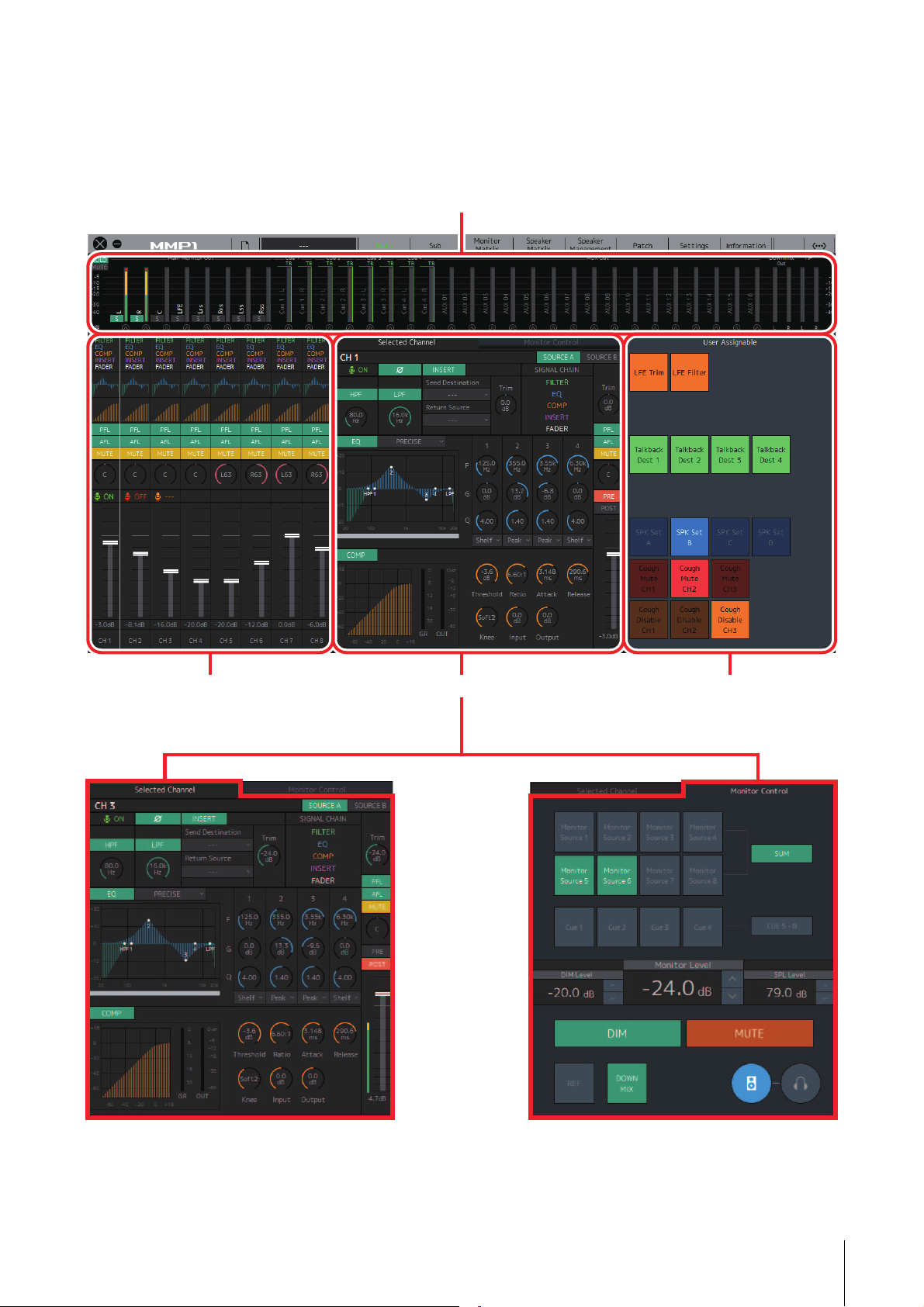
4-1-2. Main screen
Meters
Displays Monitor Matrix Out meters
Channel strips
For setting EQ, compressor, insert, pan,
output level and other values for each
channel strip
User Assignable functions
For displaying and enabling operation
of User Assignable functions
Click the tabs to change
Selected Channel tab
For fine-tuning of the parameters for the selected
channel strip
Monitor Control tab
For selecting the audio being monitored and setting
Monitor output levels
This is the Main screen used for monitor control.
NOTE
This screen can be used by all User Types.
4. Screens
MMP1 Operation Manual 8
Page 9
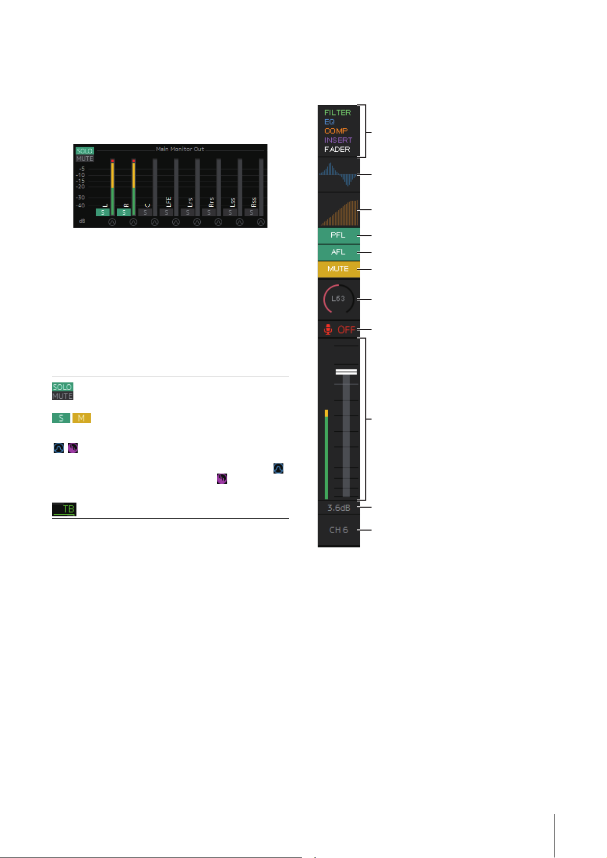
4. Screens
Displays the signal processors applied to audio
signals in the order in which they are applied
(descending order).
Displays the EQ graph.
Displays the COMP graph.
Turns output to the PFL (Pre Fader Listen) bus on
(green) or off.
Turns output to the AFL (After Fader Listen) bus
on (green) or off.
Turns mute on (yellow) or off.
Drag or use the mouse wheel to set the pan value.
To return the setting to the center, simultaneously
hold down the <Ctrl> key (Windows) or the
<command> key (Mac) and click on the control.
Shows the status of mics controlled with the
Commentary functions.
Drag or use the mouse wheel to set output level.
To return the setting to 0 dB, simultaneously hold
down the <Ctrl> key (Windows) or the
<command> key (Mac) and click on the control.
Displays the output level.
Double click to enter a value.
Displays the channel name.
Double click to change the name.
4-1-2a. Meters
Here you can display Monitor Matrix Out meters. These
channels include Monitor outputs (up to 32 ch), Downmix
L/R, and Headphone L/R.
NOTE
The meters shown here are the same as those on the Sub screen.
Values less than -20 dB are displayed in green , values
less than 0 dB in yellow , and values equal to or above 0
in red . Peak hold circuits are not displayed.
NOTE
• The breakdown of Monitor outputs is based on the format
selected under “Monitor Matrix Out” in the “Monitor Matrix” tab
of the “Scene” tab on the Settings screen.
• The signal position displayed on the meters can be selected in
the “System” tab of the “Scene” tab on the Settings screen.
4-1-2b. Channel strips
For setting EQ, compressor, insert, pan, output level and
other values for each channel strip.
Click these buttons to set all Main Monitor
outputs to SOLO or MUTE.
/ Click these buttons to turn each Main Monitor
Click these buttons to turn the oscillator on (lit)
SOLO or MUTE setting on (lights up) or off.
or off. You can select the oscillator type used in
the “Oscillator” section on the Sub screen.
represents sine waves and represents pink
noise.
This is displayed when using Talkback.
NOTE
• Eight channel strips are available when the MMP1’s sample
rate is 96 kHz or less, and four channel strips are available
when the MMP1’s sample rate being used is higher than
96 kHz. You can change the sample rate in the “MISC” tab of
the “Scene” tab on the Settings screen.
• Set channel strip input sources in “Channel Strip In” on the
Patch screen, and switch between these using “SOURCE A”
and “SOURCE B” on the “Selected Channel” tab on the Main
screen.
• Click to select a channel strip, and then set the parameters in
the “Selected Channel” tab on the Main screen.
• To bring up the context menu, (for Windows) right click
anywhere within the section, or (for Mac) hold down the
<control> key and then click in the section.
MMP1 Operation Manual 9
Page 10
4. Screens
PFL
AFL
Level meter
Fader
Output level
Channel name
Turn this on (green) to send outputs to Main
Monitors 1 and 2 while muting outputs from
Main Monitor 3 onwards.
Turn this on (green) to send outputs to Main
Monitors 1 and 2 while muting outputs from
Main Monitor 3 onwards. When “PFL” is on,
signals will not be sent to the Main Monitors
even when this button is turned on.
Shows the status of mics controlled with the
Commentary functions.
Shows the mic audio is being input.
Shows that the mic user has muted
mic audio.
Shows that the mic on and off
control by the mic user is disabled.
NOTE
• Select or deselect the “Show Cough
Status” check box of the “Editor” tab on the
Settings screen to show or hide this status
display.
• Set GPI inputs/outputs in the “GPI” tab of
the “Global” tab on the Settings screen
and use the device connected to the
MMP1 GPI [INPUT] connector to turn mics
on or off. This can also be operated using
buttons created in the “User Assignable”
tab of the “Scene” tab.
Values less than -20 dB are displayed in
green
, values less than 0 dB in yellow ,
and values equal to or above 0 in red
Peak hold circuits are not displayed.
Double click on a position to move the fader
there.
Out-of-range values entered will be corrected
to the maximum or minimum value allowed.
You can also use the mouse wheel to change
the output level.
Enter a channel name of up to
17 alphanumeric characters and symbols.
To insert a line break at any point,
simultaneously hold the <Alt> key and press
<Enter> (Windows), or hold the <option> key
and press <return> (Mac).
.
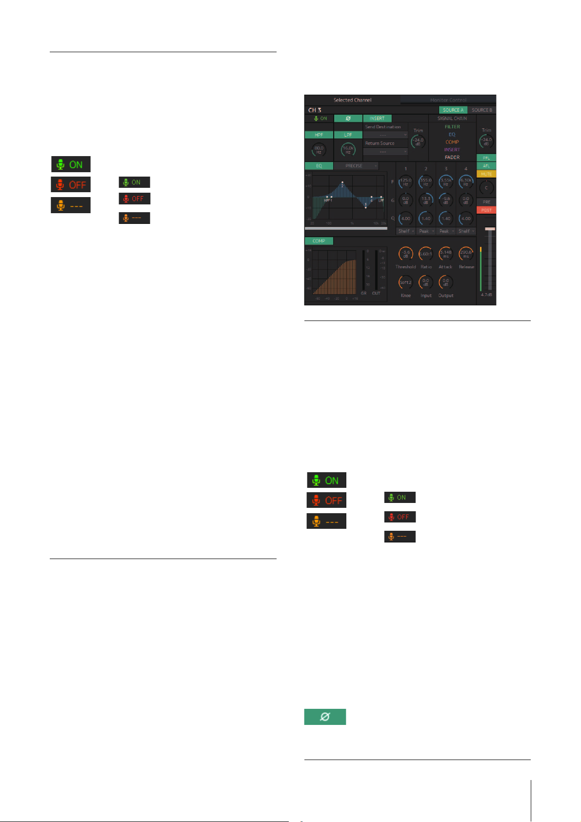
4-1-2c. Selected Channel tab
Here you can fine-tune the parameters for the selected
channel strip.
Channel name
SOURCE A/
SOURCE B
Double click to change. Enter a channel
name up to 17 alphanumeric characters
and symbols. To insert a line break at any
point, simultaneously hold the <Alt> key
and press <Enter> (Windows), or hold the
<option> key and press <return> (Mac).
Switches between channel strip input
sources.
NOTE
The input source (A/B) can be set using
“Channel Strip In” of the “Input Patch” tab
on the Patch screen.
Shows the status of mics controlled with
the Commentary functions.
Shows the mic audio is being
input.
Shows that the mic user has
muted mic audio.
Shows that the mic on and off
control by the mic user is
disabled.
NOTE
• Select or deselect the “Show Cough
Status” check box of the “Editor” tab on
the Settings screen to show or hide this
status display.
• Set GPI inputs/outputs in the “GPI” tab
of the “Global” tab on the Settings
screen and use the device connected
to the MMP1 GPI [INPUT] connector to
turn mics on or off. This can also be
operated using buttons created in the
“User Assignable” tab of the “Scene”
tab.
HPF
Click to switch between the signal phases
(normal phase/reversed phase (green)).
Click to turn the HPF (High Pass Filter) on
(green) or off.
MMP1 Operation Manual 10
Page 11
4. Screens
HPF cutoff
frequency
LPF
LPF cutoff
frequency
INSERT
Send Destination
Return Source
(Insert) Trim
SIGNAL CHAIN
EQ
PRECISE
Drag or use the mouse wheel to change
the HPF cutoff frequency. To return the
setting to 80 Hz, simultaneously hold
down the <Ctrl> key (Windows) or the
<command> key (Mac) and click on the
control.
Click to turn the LPF (Low Pass Filter) on
(green) or off.
Drag or use the mouse wheel to change
the LPF cutoff frequency. To return the
setting to 16 kHz, simultaneously hold
down the <Ctrl> key (Windows) or the
<command> key (Mac) and click on the
control.
Click to turn the Insert on (green) or off.
Select the signal to send to the Insert.
Select the signal to be returned from the
Insert.
Drag or use the mouse wheel to adjust
signal levels to be sent to the Insert. To
return the setting to 0 dB, simultaneously
hold down the <Ctrl> key (Windows) or
the <command> key (Mac) and click on
the control.
Displays the signal processors applied to
audio signals in the order in which they
are applied (descending order).
Click to turn the EQ on (green) or off.
You can choose from the following four EQ
algorithms. The color of the bar at the
bottom of the EQ graph will change based
on the algorithm selected.
This EQ strives for ultimate precision and
controllability. It enables you to adjust the
target point precisely, and flexibly satisfies
various requirements for sound making.
Low/High Shelving filters feature a “Q”
parameter, which enables you to adjust
the knee characteristics.
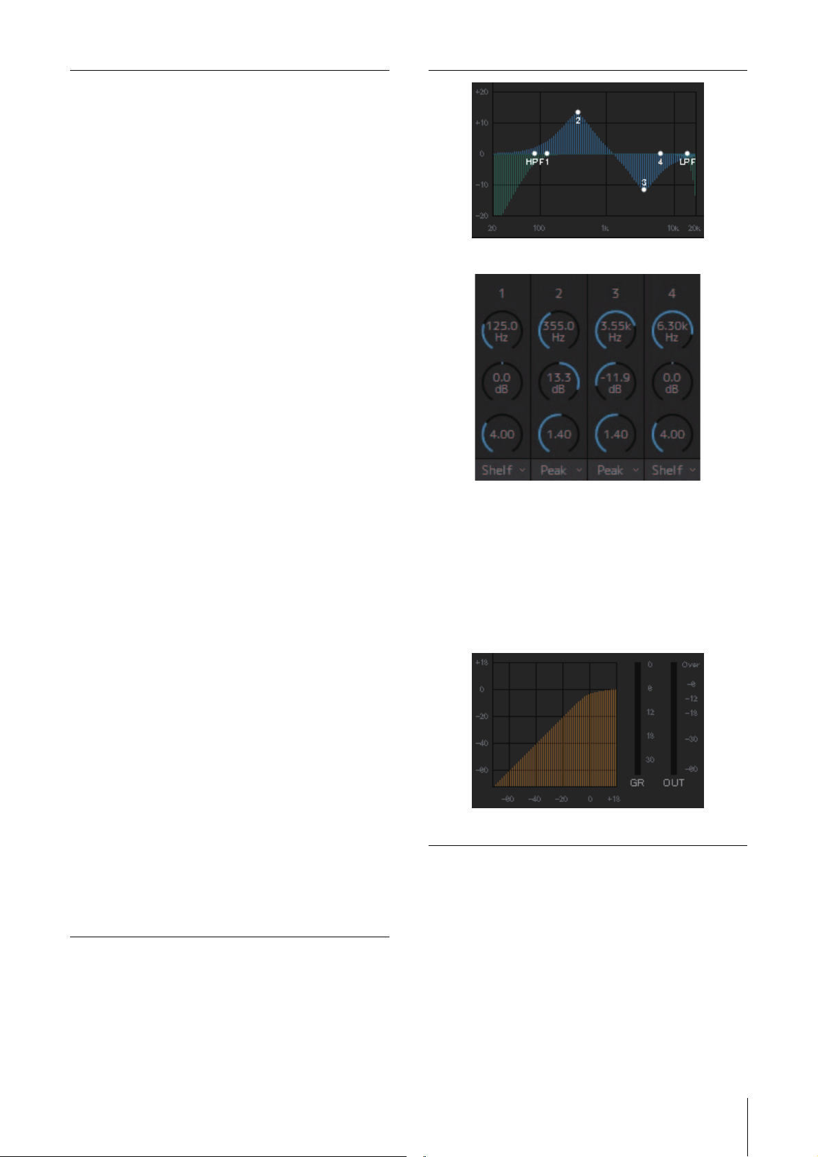
Displays the EQ graph and filters.
Drag or use the mouse wheel to change four band EQ
parameters (Frequency, Gain, Q). To return these parameters to
their default values, simultaneously hold down the <Ctrl> key
(Windows) or the <command> key (Mac) and click on the
corresponding control. Default values are F: 125 Hz/355 Hz/
3.55 kHz/6.3 kHz, G: 0 dB, and Q: 4.0 (Shelf)/1.4 (Peak)/1.0
(Notch). You can also select the EQ type from Peak and Shelf
(Shelving), or Peak and Notch.
COMP
Click to turn the compressor on (green) or
off.
AGGRESSIVE
SMOOTH
LEGACY
This EQ is musical and effective. It
enables you to add a powerful, creative
edge and serves as a powerful tool for
artistic expression.
This EQ focuses on smooth sound
qualities. It contributes to a natural sound
without changing the atmosphere of the
original.
This is the standard EQ that has been
provided on Yamaha digital mixers since
the PM1D and PM5D.
Displays the COMP graph together with the GR meter and the
OUT meter.
MMP1 Operation Manual 11
Page 12

4. Screens
Drag or use the mouse wheel to change compressor parameters.
To return these parameters to their default values, simultaneously
hold down the <Ctrl> key (Windows) or the <command> key
(Mac) and click on the corresponding control. (shown in the table
below).
Threshold:
Ratio:
Attack:
Release:
Knee:
Input:
Output:
Tri m
0.0 dB
1.00: 1
3.148 ms
290.6 ms
Soft 2
0.0 dB
0.0 dB
Drag or use the mouse wheel to adjust the
output level for the selected channel. To
return the output level to 0 dB,
simultaneously hold down the <Ctrl> key
(Windows) or the <command> key (Mac)
and click on the control.
Fader
Output level
Drag or use the mouse wheel to set output
levels. To return the setting to 0 dB,
simultaneously hold down the <Ctrl> key
(Windows) or the <command> key (Mac)
and click on the control.
Displays the output level. Double click to
enter a value. Out-of-range values
entered will be corrected to the maximum
or minimum value allowed. You can also
use the mouse wheel to change the
output level.
PFL
AFL
MUTE
PA N
PRE
POST
Level meter
Click to turn output to the PFL (Pre Fader
Listen) bus on (green) or off. Turn this on
to send pre fader audio signals to Main
Monitors 1 and 2 while muting outputs
from Main Monitor 3 onwards.
Click to turn output to the AFL (After Fader
Listen) bus on (green) or off. Turn this on
to send post fader audio signals to Main
Monitors 1 and 2 while muting outputs
from Main Monitor 3 onwards. When “PFL”
is on, signals will not be sent to the Main
Monitors even when this button is turned
on.
Click to turn mute on (yellow) or off.
Drag or use the mouse wheel to set the
pan. To return pan to the center position,
simultaneously hold down the <Ctrl> key
(Windows) or the <command> key (Mac)
and click on the control.
Click to change the position (pre fader/
post fader) of the signal displayed on the
meter.
Values less than -20 dB are displayed in
, values less than 0 dB in
green
, and values equal to or above 0
yellow
in red
. Peak hold circuits are not
displayed. To change whether pre fader
or post fader values are displayed, use
the “PRE” and “POST” controls above.
MMP1 Operation Manual 12
Page 13
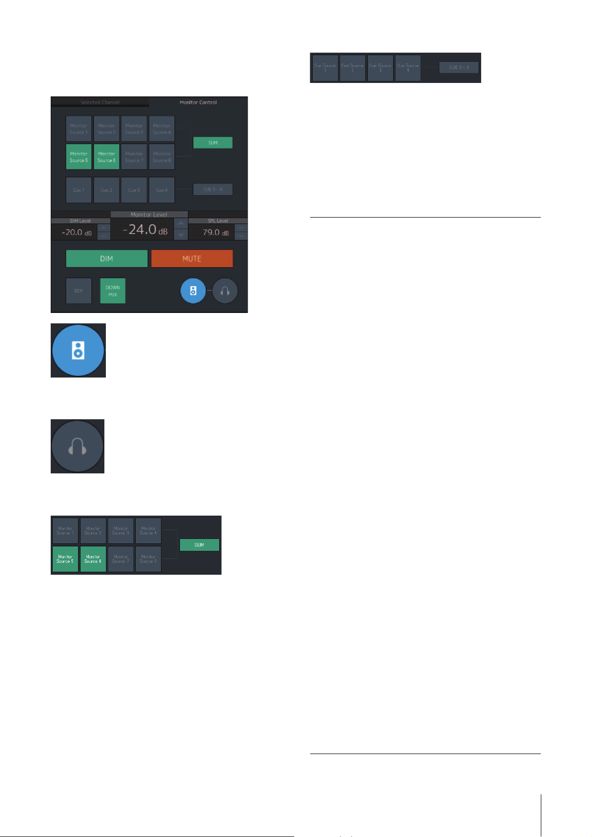
4-1-2d. Monitor Control tab
Here you can select the audio being monitored and set
Monitor output levels.
4. Screens
Select the audio to be monitored from the available Cue
outputs. To change the available Cue outputs for selection
to Cue 5 - Cue 8, turn “Cue 5-8” on (green).
NOTE
• Select the format for Cue Sources 1-8 under the “Monitor
Matrix Out” in the “Monitor Matrix” tab of the “Scene” tab on the
Settings screen.
• You can confirm that the input source to the Cue outputs is
turned on (displayed in green) on the Monitor Matrix screen.
This is used to enable operation of the Main Monitor
outputs.
This is used to enable operation of the headphone
outputs.
Monitor Level
or Headphone
Monitor Level
DIM
DIM Level
Click “u” or “d,” or use the mouse wheel to
set Monitor output level. Double click to
enter a value directly. Out-of-range values
entered will be corrected to the maximum or
minimum value allowed.
NOTE
• You can use the mouse wheel while
holding down <Shift> to make minor
adjustments.
• Changing this value will also change the
SPL value.
Click to turn the dimmer on (green) or off.
Turn this on to lower Monitor output for the
DIM Level without changing the Monitor
Level.
NOTE
This button will be on (displayed in green)
and cannot be changed while talkback is on
when “Dim main monitor while talkback is
on” is checked (in the General settings of
the “Global” tab on the Settings screen).
Click “u” or “d,” or use the mouse wheel to
set the attenuation amount of the Monitor
output signal when the dimmer is on. Double
click to enter a value directly. Out-of-range
values entered will be corrected to the
maximum or minimum value allowed.
Select the audio to be monitored from the Monitor Sources
available. Turn “SUM” on (green) to select multiple
Monitor Sources at the same time.
NOTE
• Select the format for Monitor Sources 1-8 under “Monitor Matrix
In” in the “Monitor Matrix” tab of the “Scene” tab on the
Settings screen, and then assign input sources for each in the
“Monitor Matrix In” section on the Patch screen or the Monitor
Matrix screen.
• You can confirm the destination of Monitor Sources sent to on
(displayed in green) on the Monitor Matrix screen.
SPL Level
MUTE
REF
Click “u” or “d,” or use the mouse wheel to
set the SPL to enter a value directly. Out-ofrange values entered will be “--.- dB,” and
the SPL setting will be off.
As Monitor Level values are tied to the SPL
when the SPL is set, the SPL value will
change when changing the Monitor Level
value.
For example, changing a Monitor Level of
-10 dB to -20 dB when an SPL value of
85 dB is set will result in the SPL value
changing to 75 dB.
Click to turn the Monitor output mute on
(orange) or off.
Click to change the Monitor Level value to
the reference level value.
Holding this down for at least two seconds
(until the indicator flashes) stores the current
Monitor Level value as the reference level.
MMP1 Operation Manual 13
Page 14

4. Screens
DOWNMIX
Click to turn the Downmix audio output on
(green) or off.
Turn this on to send Downmix L/R outputs to
Main Monitors 1 and 2 while muting outputs
from Main Monitor 3 onwards.
NOTE
This button is disabled when the Cue output
format is selected as the audio being
monitored.
4-1-2e. User Assignable functions
Here you can display and use User Assignable functions.
This displays functions registered in the “User
Assignable” tab of the “Scene” tab on the Settings screen.
Depending on the particular functions registered, these
may appear and function as:
• An on/off button (an latch type button that switches on
and off each time you click it)
• A push button (a momentary type button that works
while the button is held down)
• A display indication only
MMP1 Operation Manual 14
Page 15
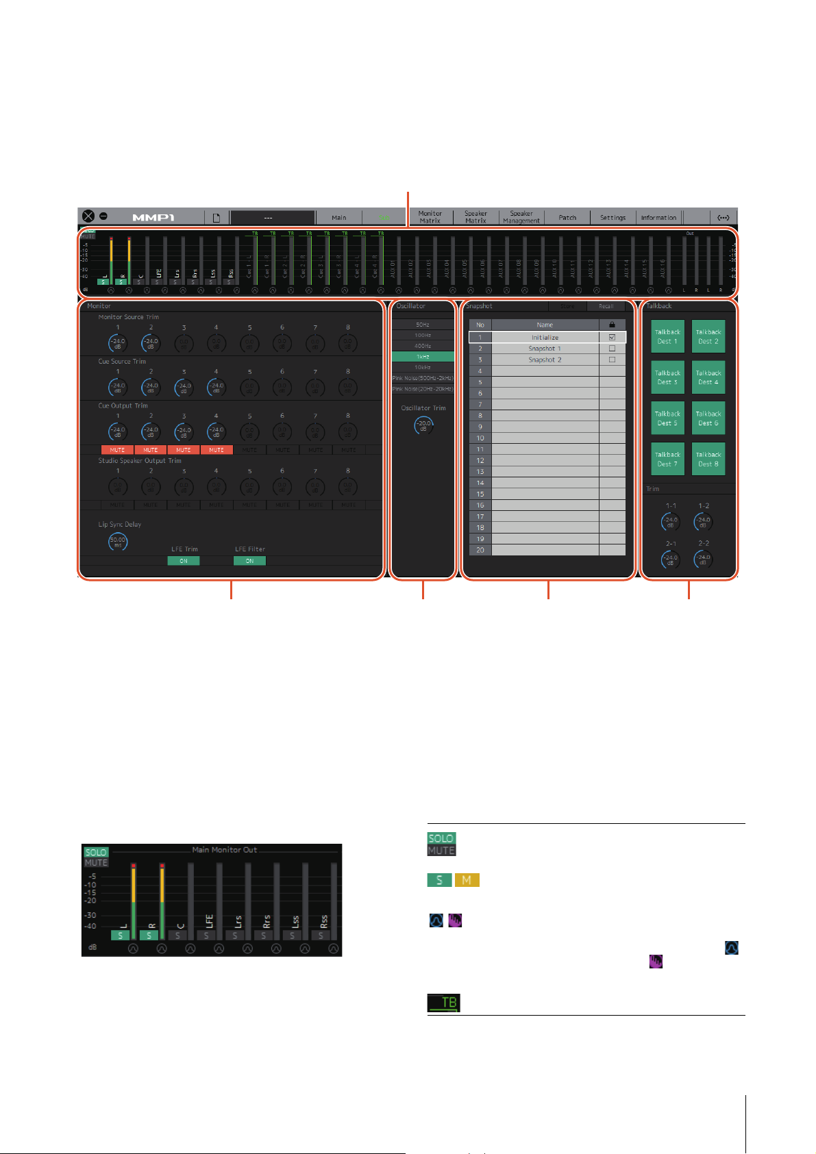
4-1-3. Sub screen
Meters
Displays Monitor Matrix Out meters
Monitor section
For adjusting input source and Send levels
Oscillator section
For selecting signals
to output from the
oscillator, and
adjusting their output
levels
Snapshot section
For storing and recalling
Snapshots
Talkback section
For selecting Talkback
interrupt destinations
and adjusting Talkback
output levels
This is the Sub screen used for monitor control.
NOTE
You can use this screen when logged in as an “Administrator” or “Advanced User.”
4. Screens
4-1-3a. Meters
Here you can display Monitor Matrix Out meters. These
channels include Monitor outputs (up to 32 ch), Downmix
L/R, and Headphone L/R.
NOTE
The meters shown here are the same as those on the Main
screen.
Values less than -20 dB are displayed in green , values
less than 0 dB in yellow , and values equal to or above 0
in red . Peak hold circuits are not displayed.
NOTE
• The breakdown of Monitor outputs is based on the format
selected under “Monitor Matrix Out” in the “Monitor Matrix” tab
of the “Scene” tab on the Settings screen.
• The signal position displayed on the meters can be selected in
the “System” tab of the “Scene” tab on the Settings screen.
Click these buttons to set all Main Monitor
outputs to SOLO or MUTE.
/ Click these buttons to turn each Main Monitor
SOLO or MUTE setting on (lights up) or off.
Click these buttons to turn the oscillator on (lit)
or off. You can select the oscillator type used in
the “Oscillator” section on the Sub screen.
represents sine waves and represents pink
noise.
This is displayed when using Talkback.
MMP1 Operation Manual 15
Page 16
4. Screens
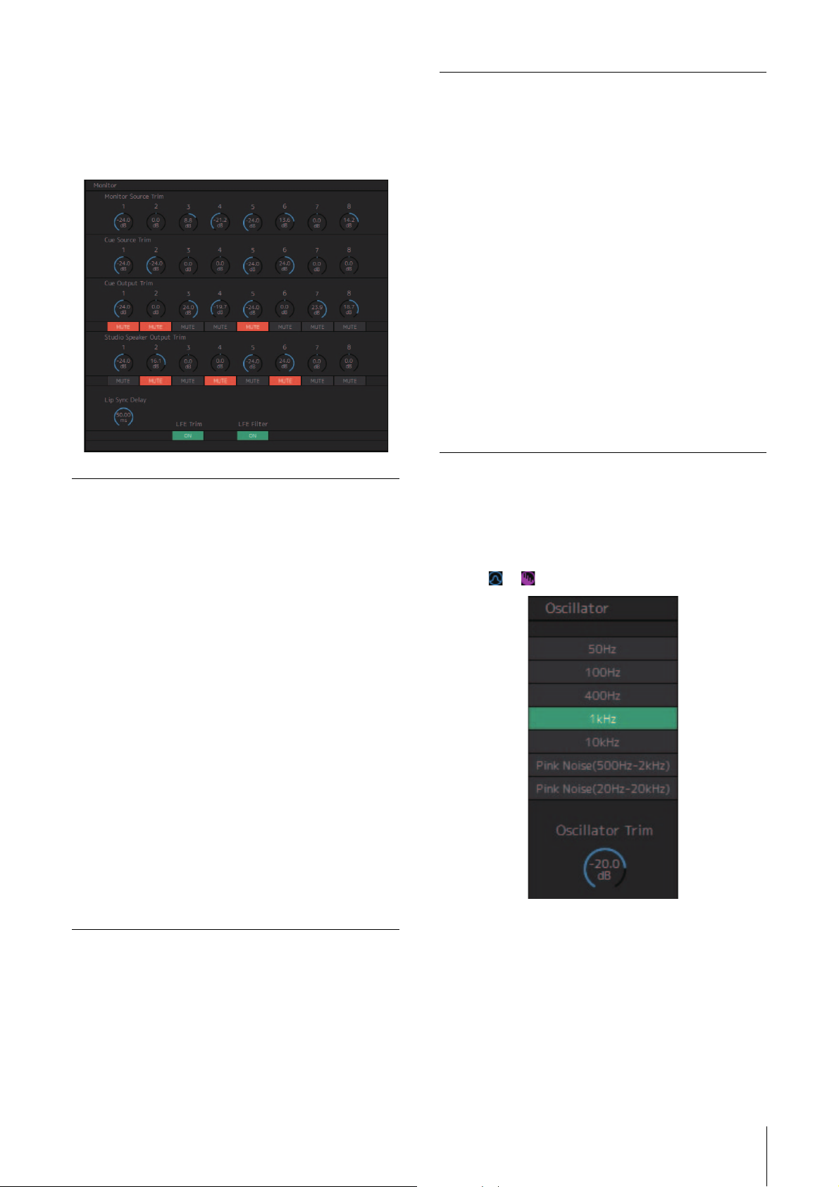
4-1-3b. Monitor section
Here you can adjust the input source and Send levels.
NOTE
Control the sources and outputs of the format selected in the
“Monitor Matrix” tab of the “Scene” tab on the Settings screen.
LFE Trim
LFE Filter
Click to turn the LFE Trim on (green) or off.
Turn this on to add an LFE Trim Level to all
channels where the CH Type has been set
to “LFE” in the “Speaker Matrix” tab of the
“Scene” tab on the Settings screen.
NOTE
• You can set the CH Type in the “Speaker
Matrix” tab of the “Scene” tab on the
Settings screen.
• You can set the LFE Trim Level in the
“MISC” tab of the “Scene” tab on the
Settings screen.
Click to turn the LFE Filter on (green) or off.
Turn this off to change the crossover filter
for LFE channels in the following ways.
FIR THRU
IIR (Bypass)
THRU THRU (Unchanged)
NOTE
Note that while filters will not be applied
when the crossover filter is set to “THRU,”
the same delay as that applied to the main
channel will be added.
Monitor Source
Tri m
Cue Source Trim
Cue Output Trim
Studio Speaker
Output Trim
Lip Sync Delay
Drag or use the mouse wheel to adjust
Monitor Source levels. To return the setting
to 0 dB, simultaneously hold down the
<Ctrl> key (Windows) or the <command>
key (Mac) and click on the control.
Drag or use the mouse wheel to adjust Cue
Source levels. To return the setting to 0 dB,
simultaneously hold down the <Ctrl> key
(Windows) or the <command> key (Mac)
and click on the control.
Drag or use the mouse wheel to adjust Cue
output levels. To return the setting to 0 dB,
simultaneously hold down the <Ctrl> key
(Windows) or the <command> key (Mac)
and click on the control. Click “MUTE” to
mute.
Drag or use the mouse wheel to adjusts
studio speaker output levels. To return the
setting to 0 dB, simultaneously hold down
the <Ctrl> key (Windows) or the
<command> key (Mac) and click on the
control. Click “MUTE” to mute.
Drag or use the mouse wheel to set the lip
sync delay. To return the setting to 0 ms,
simultaneously hold down the <Ctrl> key
(Windows) or the <command> key (Mac)
and click on the control.
4-1-3c. Oscillator section
Here you can select signals to output from the oscillator,
and adjust their output levels.
NOTE
Click the or of the meter to turn the oscillator on or off.
Oscillator Trim
Drag or use the mouse wheel to set Oscillator levels. To
return the setting to -20 dB, simultaneously hold down the
<Ctrl> key (Windows) or the <command> key (Mac) and
click on the control.
MMP1 Operation Manual 16
Page 17
4. Screens
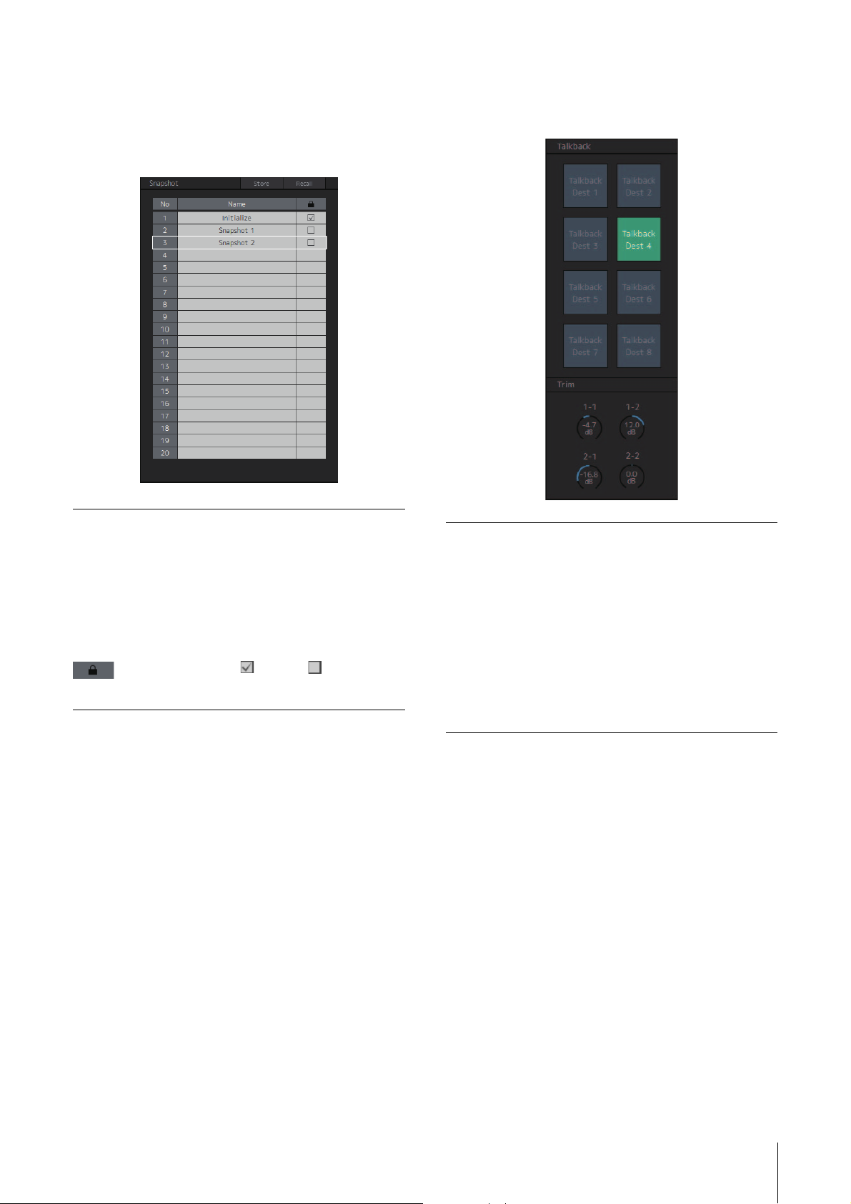
4-1-3d. Snapshot section
Here you can store parameters at a set point in time as
Snapshots to be loaded later as desired or needed.
NOTE
Up to 20 Snapshots can be stored per Scene.
4-1-3e. Talkback section
Here you can select Talkback interrupt destinations and
adjust Talkback output levels.
Store
Recall
Name
Click to store a Snapshot at the selected
location.
Click to recall (load) the selected Snapshot.
Click to select a Snapshot (or an empty field).
Double click to change the name entered.
Enter a channel name up to 17 alphanumeric
characters and symbols.
Click to lock or unlock a Snapshot.
Locked Snapshots cannot be overwritten by
selecting Store.
NOTE
To bring up the context menu, (for Windows) right click anywhere
within the section, or (for Mac) hold down the <control> key and
then click in the section.
Talkba ck
Click to turn the Talkback on (green) or off.
NOTE
Set Talkback inputs and interrupt destinations
in the “Talkback Mic In” of the “Input Patch”
tab on the “Patch” screen and “Talkback
Destination” tab of the “Scene” tab on the
Settings screen.
Tri m
Drag or use the mouse wheel to adjust
Talkback levels. To return the setting to 0 dB,
simultaneously hold down the <Ctrl> key
(Windows) or the <command> key (Mac)
and click on the control.
NOTE
You can set the amount that the audio output of interrupt
destination is reduced (dimmed) when Talkback is turned on by
using “Talkback Dim Level” in the “MISC” tab of the “Scene” tab
on the Settings screen.
MMP1 Operation Manual 17
Page 18
4. Screens
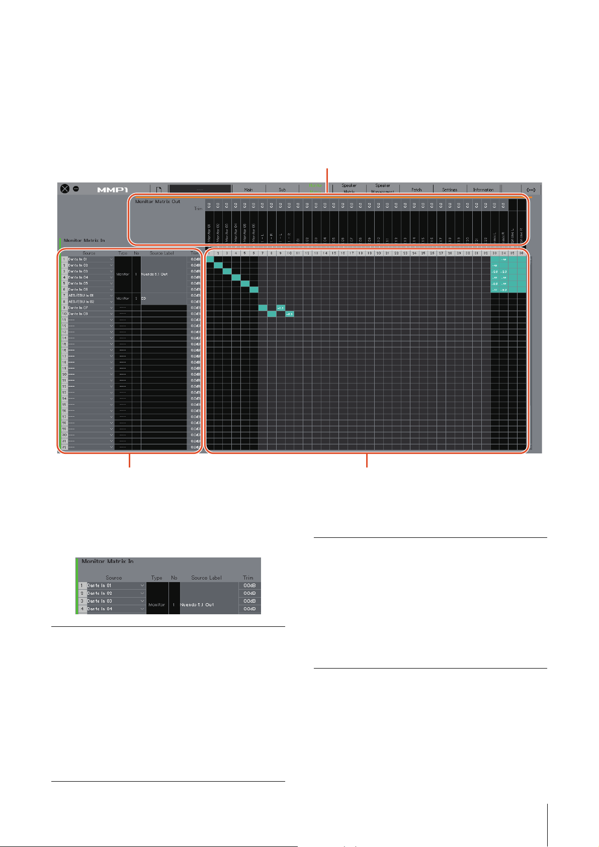
Monitor Matrix Out
Monitor Matrix Out names appear here. Adjust output levels here
Monitor Matrix In
For selecting input sources, and
adjusting the levels of the selected
input sources
Monitor matrix
For turning the Send output from Monitor Matrix In to Out on (green) or off,
and setting Send levels
4-1-4. Monitor Matrix screen
This screen is used for routing monitor signals.
NOTE
• You can use this screen when logged in as an “Administrator” or “Advanced User.”
• This matrix is set to 40x36 when the MMP1’s sample rate is 96 kHz or less, and 20x20 when the MMP1’s sample rate being used is higher
than 96 kHz. You can change the sample rate in the “MISC” tab of the “Scene” tab on the Settings screen.
Monitor Matrix In
Source
Typ e & N o
For selecting monitor matrix input sources.
NOTE
The same items can be configured on the
“Input Patch” tab on the Patch screen.
The Monitor Matrix In input type. Monitor
Sources 1-8 will appear as Monitor 1-8, Cue
Sources 1-8 as Cue 1-8, and other inputs will
be “---” and blank.
NOTE
You can select the format for Monitor 1-8 and
Cue 1-8 in the “Monitor Matrix” tab of the
“Scene” tab on the Settings screen.
Source Label
Tri m
If the Type is “Monitor” or “Cue,” double click
to add a name (label). Enter a channel name
up to 17 alphanumeric characters and
symbols. To insert a line break at any point,
simultaneously hold the <Alt> key and press
<Enter> (Windows), or hold the <option> key
and press <return> (Mac).
Double click or use the mouse wheel to
adjust input levels. Out-of-range values
entered will be corrected to the maximum or
minimum value allowed.
MMP1 Operation Manual 18
Page 19

Monitor Matrix Out Monitor matrix
4. Screens
Name (Label)
Tri m
Displays Monitor Matrix Out names.
NOTE
• The breakdown of Monitor Matrix Out is
based on the format selected in the
“Monitor Matrix” tab of the “Scene” tab on
the Settings screen.
• You can add Monitor Matrix Out names
(labels) in the “MISC” tab of the “Scene”
tab on the Settings screen.
Double click or use the mouse wheel to
adjust output levels. Out-of-range values
entered will be corrected to the maximum or
minimum value allowed.
NOTE
When the Cue and Studio Speaker format is
set to stereo, the same settings will be
applied to both L/R.
• Click to turn Send on (green) or off. When a cell has
been turned on, a signal will be sent from the cell row
(the input source) to the cell column (output).
• To turn multiple cells on or off at the same time,
simultaneously hold down the right mouse button
(Windows) or the <control> key (Mac) and then drag
and release the button (key).
Quick Assign:
On:
Turns entire dragged area on (green)
Off:
Turns entire dragged area off
Criss cross from dragging origin point
• Right click (Windows), or hold down the <control> key
and then click (Mac) on a cell that has been turned on
(appearing in green) to set Send levels. Out-of-range
values entered will be corrected to the maximum or
minimum value allowed.
• If the input source is the channel strip (Ch 1-8), right
click (Windows), or hold down the <control> key and
then click (Mac) to select either “Mono,” “L,” or “R.”
• If the Monitor Source format has been selected in the
“Monitor Matrix” tab of the “Scene” tab on the Settings
screen, you cannot set Monitor Sources 1-8 to send to
the Main Monitor, Downmix L/R, or Headphone L/R on
this screen.
Use the “Monitor Control” tab on the Main screen to turn
these Send signals on or off (described in detail below).
Send signals to the Main Monitor: Use the “Monitor
Source” selection button to turn Send on or off.
Send signals to Downmix L/R: Use the “Monitor
Source” selection button to turn Send on or off.
Send signals to Headphone L/R: Set the target to
headphone output, and then use the “Monitor Source”
selection button to turn Send on or off.
MMP1 Operation Manual 19
Page 20
4. Screens
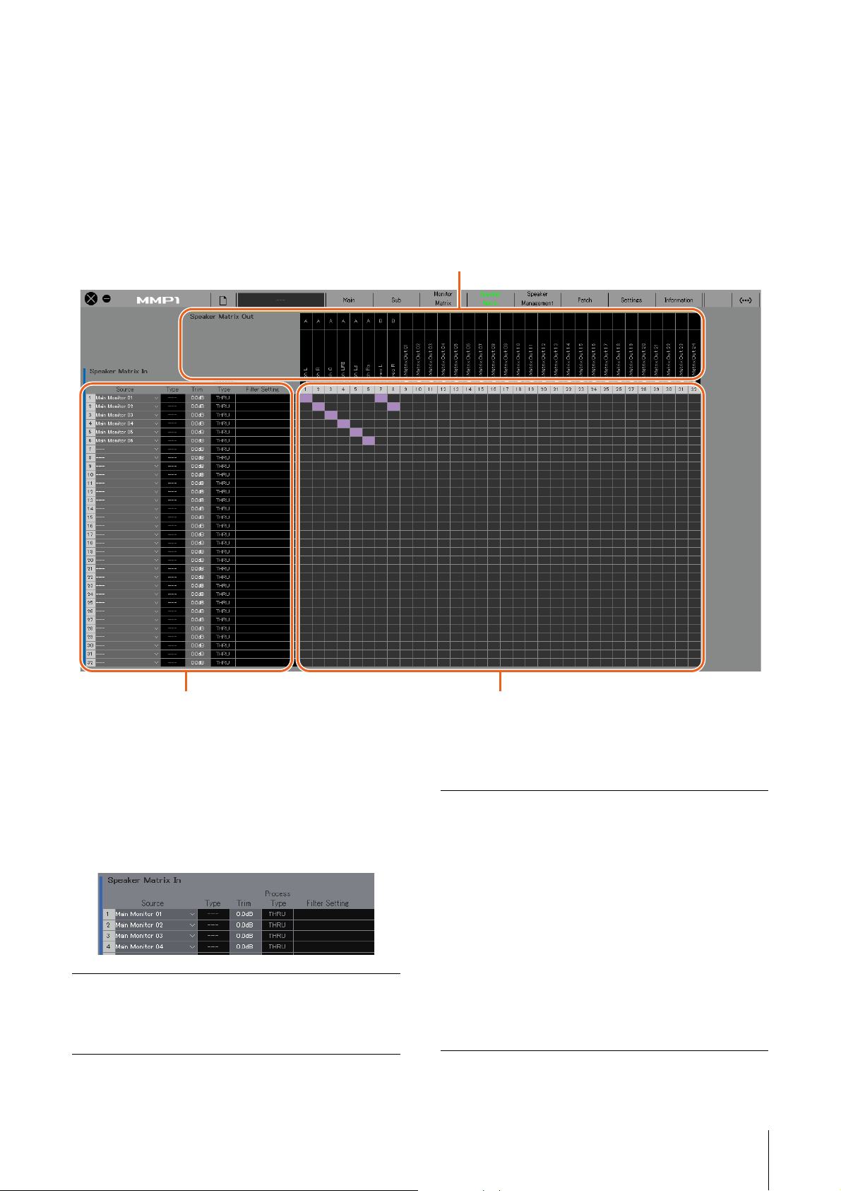
Speaker Matrix Out
Displays Speaker Matrix Out names
Speaker Matrix In
For selecting input sources, and
adjusting the levels of the selected input
sources
Speaker matrix
Click to turn Send on (purple) or off from Speaker Matrix In to Out
4-1-5. Speaker Matrix screen
This screen is used for routing input signals and speakers.
NOTE
• You can use this screen when logged in as an “Administrator” or “Advanced User.”
• Cells with black backgrounds can be used in the “Speaker Matrix” tab of the “Scene” tab on the Settings screen when logged in as an
Administrator.
• This matrix is 32x32 when the MMP1's sample rate is 96 kHz or less, and 16x16 when the MMP1's sample rate being used is higher than
96 kHz. You can change the sample rate in the “MISC” tab of the “Scene” tab on the Settings screen.
NOTE
Refer to page 59 when configuring bass management.
Speaker Matrix In
Source
For selecting speaker matrix input sources.
NOTE
The same items can be configured on the
“Input Patch” tab on the Patch screen.
Type
Tri m
The input type to the speaker matrix (“Monitor”
or “LFE”) will appear here.
NOTE
You can set the Type (CH Type) in the
“Speaker Matrix” tab of the “Scene” tab on the
Settings screen.
Double click or use the mouse wheel to adjust
input levels. Out-of-range values entered will
be corrected to the maximum or minimum
value allowed.
NOTE
When the Type (CH Type) is “LFE,” and the
“LFE Trim” button in the “Monitor” section on
the Sub screen is set to on, the LFE Trim Level
will be added to the input value.
MMP1 Operation Manual 20
Page 21
4. Screens
Process Type
Displays the crossover filter type.
NOTE
• You can set the crossover filter type in the
“Speaker Matrix” tab of the “Scene” tab on
the Settings screen.
• The color of the text will be orange when the
FIR filter is temporarily changed to the IIR
filter with the talkback or User Assignable
function.
Filter Setting
Displays the high pass/low pass filter type and
cutoff frequency.
NOTE
You can set the high pass/low pass filter type
and cutoff frequency in the “Speaker Matrix”
tab of the “Scene” tab on the Settings screen.
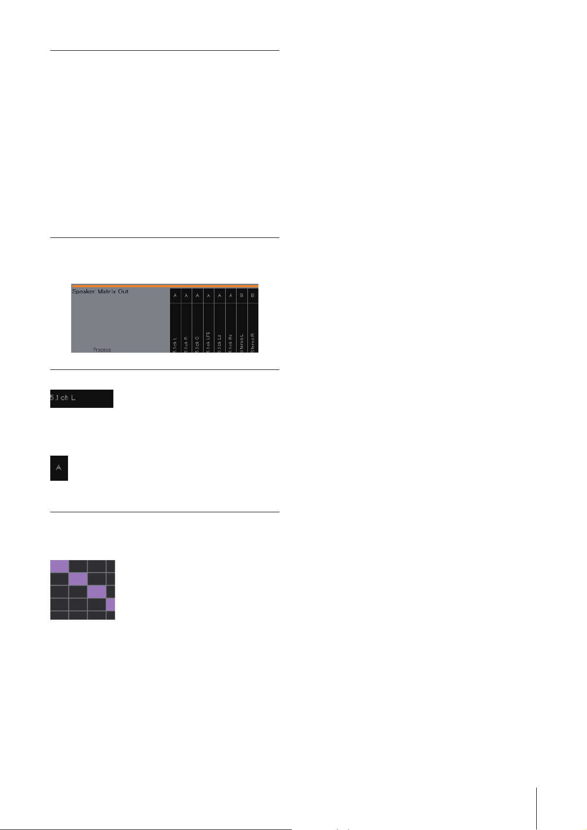
Speaker Matrix Out
Name (Label)
Display the Speaker Matrix Out names.
NOTE
You can change the names (labels) of
Speaker Matrix Out in the “MISC” tab of the
“Scene” tab on the Settings screen.
Speaker Set
Displays the Speaker Set to which the
Speaker Matrix Out belongs.
NOTE
You can set the Speaker Set in “Speaker
Matrix” tab of the “Scene” tab on the Settings
screen.
Speaker matrix
• Click to turn Send on (purple) or off. When a cell has
been turned on, a signal will be sent from the cell row
(the input source) to the cell column (output).
• To turn multiple cells on or off at the same time,
simultaneously hold down the right mouse button
(Windows) or the <control> key (Mac) and then drag
and release the button (key).
Quick Assign: Criss cross from dragging origin point
On: Turns entire dragged area on (purple)
Off:
Turns entire dragged area off
MMP1 Operation Manual 21
Page 22

4-1-6. Speaker Management screen
This is used to set the delay and EQ for signals sent to each speaker.
NOTE
You can use this screen when logged in as an “Administrator” or “Advanced User.”
4. Screens
Speaker Matrix Out
Speaker Set
Tri m
Delay
EQ 1 – 6
Displays the Speaker Set to which the
Speaker Matrix Out belongs.
NOTE
You can set the Speaker Set in “Speaker
Matrix” tab of the “Scene” tab on the Settings
screen.
Double click or use the mouse wheel to
adjust input levels. Out-of-range values
entered will be corrected to the maximum or
minimum value allowed.
Double click or use the mouse wheel to set
the delay. Out-of-range values entered will be
corrected to the maximum or minimum value
allowed.
Double click or use the mouse wheel to set
the F (frequency), G (gain), Q, and Type for
the EQ. Out-of-range values entered will be
corrected to the maximum or minimum value
allowed.
NOTE
• To bring up the context menu, (for Windows) right click a value,
or (for Mac) hold down the <control> key and then click a
value.
• To select multiple cells for copying values to, simultaneously
hold down the right mouse button (Windows) or the <control>
key (Mac) and drag the mouse.
Direct Speaker Send
For selecting input sources to send to each speaker
without going through the speaker matrix. Delay, EQ and
other processing cannot be performed.
This is used to switch between Speaker Sets when the
speaker matrix is being used for another application.
Click to select an input source.
NOTE
The same items can be configured on the
“Input Patch” tab on the Patch screen.
MMP1 Operation Manual 22
Page 23

4. Screens
4-1-7. Patch screen
This screen is used to assign input sources and outputs to channels within the MMP1 Editor and I/O connectors.
The Patch screen is split into the “Input Patch” tab and the “Output Patch” tab. Click these tabs to switch between the two.
NOTE
You can use this screen when logged in as an “Administrator” or “Advanced User.”
4-1-7a. Input Patch
Monitor Matrix In
Channel Strip In
Speaker Matrix In
Direct Speaker Send
Talkback Mic In
• For selecting the input source to be routed on the Monitor Matrix screen.
• Up to 32 channels are available. However, only channels 1-16 will be enabled when the MMP1’s sample rate
being used is higher than 96 kHz. You can change the sample rate in the “MISC” tab of the “Scene” tab on the
Settings screen.
• You can select the format for Monitor Sources 1-8 and Cue Sources 1-8 from the “Monitor Matrix” tab of the
“Scene” tab on the Settings screen.
• For selecting the desired input source for operation using the channel strip on the Main screen.
• Channel strips are loaded in two sets, A and B. Use the “Selected Channel” tab on the Main screen to switch
between the two.
• For selecting the input source to be routed on the Speaker Matrix screen.
• Up to 32 channels are available. However, only channels 1-16 will be enabled when the MMP1’s sample rate
being used is higher than 96 kHz. You can change the sample rate in the “MISC” tab of the “Scene” tab on the
Settings screen.
• You can set the input source Type in the “Speaker Matrix” tab of the “Scene” tab on the Settings screen.
For selecting input sources to send to speakers without going through the speaker matrix.
For selecting a Talkback mic input source.
Refer to the table on page 25 for more information about input sources that can be assigned.
NOTE
While holding down the right mouse button (Windows) or the <control> key (Mac) on the Source fields, drag up or down on the fields to
select several input sources at the same time.
MMP1 Operation Manual 23
Page 24

4-1-7b. Output Patch
4. Screens
Dante Out
Analog Out
AES/EBU Out
For selecting the audio signal output from the Dante [PRIMARY]/[SECONDARY] connectors on the MMP1.
For selecting the audio signal output from the ANALOG [OUTPUT 1-8] connectors on the MMP1.
For selecting the audio signal output from the [AES/EBU 1-8]/[AES/EBU 9-16] connectors on the MMP1.
Refer to the table on page 25 for more information about audio signals that can be assigned.
NOTE
While holding down the right mouse button (Windows) or the <control> key (Mac) on the Source fields, drag up or down on the fields to
select several input sources at the same time.
MMP1 Operation Manual 24
Page 25

4-1-7c. Correspondence table of assignable audio signals
4. Screens
Source
Dante In
1-6 4
Analog In
1-8
AES/EBU In
1-16
CH Strip Out
1-8
CH Strip 1-8
Ins Send
PFL Bus Out
AFL Bus Out
RTB Bus Out
Monitor
Matrix Meter
Out 1-32
Downmix
Meter Out L/R
Headphone
Meter Out L/R
Monitor
Matrix Out
1-3 2
Downmix Out
L/R
Headphone
Out L/R
SPK Matrix
Out 1-32
Direct SPK
Out 1-6
Oscillator
Monitor
Matrix In
Input from the Dante
[PRIMARY]/[SECONDARY]
connectors on the MMP1.
Input from the ANALOG
[INPUT 1-8] connectors on
the MMP1.
Input from the [AES/EBU 1-8]/
[AES/EBU 9-16] connectors
on the MMP1.
Channel strip output signals.
Channel strip Insert Send
signals.
Pre Fader Listen for the
channel strip.
After Fader Listen for the
channel strip.
Return Talk Back. Input
signals to the channel strip
are output directly without
passing through the channel
strip.
Main Monitor, Cue, Studio
Speaker, and AUX signals
output to the meter.
Downmix L/R signals output
to the meter.
Headphone L/R signals
output to the meter.
Signals input to Monitor Matrix
Out 1-32. The sources which
can be selected depends on
the settings under the
“Monitor Matrix Out” in the
“Monitor Matrix” of the
“Scene” tab on the Settings
screen.
Signals input to Downmix Out
L/R.
Signals input to Headphone
Out L/R.
Signals input to Speaker
Matrix Out 1-32. The sources
which can be selected
depends on the “Speaker
Matrix” of the “Scene” tab on
the Settings screen.
Signals input to Direct
Speaker Send.
Internal MMP1 oscillator.
Channel
Strip In
Speaker
Matrix In
Direct
Speaker
Send
Talkback
Mic In
Dante Out
Analog Out
AES/EBU Out
MMP1 Operation Manual 25
Page 26

4. Screens
1
2
4-1-8. Settings screen
This screen is used to configure various MMP1 settings.
NOTE
• You can use this screen when logged in as an “Administrator.”
• “Scene” tab settings can be stored (saved) or recalled (loaded) as Scenes.
• “Global” tab settings will be applied to all Scenes.
• “Editor” tab settings are stored by the MMP1 Editor for each computer in use. The same settings will be applied regardless of the file or
Scene opened by the user.
4-1-8a. Scene Tab/MISC
Scene Management
Here you can store the current system configuration as a
Scene. Stored Scenes can be recalled (loaded) using the
SCENE RECALL [1] to [5] and the [RECALL] key on the
MMP1 unit itself, or from the menu bar of the MMP1 Editor.
Audio
Here you can configure the audio-related settings.
1 Click to select the Scene storage destination.
2 Click to store the Scene.
Name
• The background of the most recently recalled Scene will
be highlighted.
• Double click to change the Scene name. Enter a
channel name up to 17 alphanumeric characters and
symbols.
• To bring up the context menu, (for Windows) right click
anywhere within the section, or (for Mac) hold down the
<control> key and then click in the section.
NOTE
Set “Confirmation Store” settings to on in the “Editor” tab on the
Settings screen to display a confirmation dialog box when
attempting to store a Scene.
Sample Rate
Mono to Stereo
Assign Attenuation
Stereo to Mono
Assign Attenuation
Talkback Dim Level
LFE Trim Level
Determines the sample rate being used
by the MMP1 unit.
Determines the attenuation applied
when assigning monaural signals to
stereo outputs.
Determines the attenuation applied
when assigning stereo signals to
monaural outputs.
Determines the amount that the audio
output is reduced (dimmed) at the
interrupt destination when Talkback is
turned on. This does not affect the
Talkback voice level itself.
This trim is applied to audio when the
CH Type has been set to “LFE” in the
“Speaker Matrix” tab of the “Scene” tab.
Turn this trim on and off to configure a
system that switches between LFE
channel playback levels.
MMP1 Operation Manual 26
Page 27

4. Screens
AES / EBU SRC
Analog Input Level
For turning the SRC (Sampling Rate
Converter) on and off for two-channel
pair units for AES/EBU input/output.
For selecting the input level (+4dBu/
-10dBV) for two-channel pair units for
analog input and output.
Label
Here you can set a name (label) for Monitor Matrix Out
and Speaker Matrix Out.
Typ e
Label
Speaker Set
Displays the Monitor Matrix Out type. You can
configure type settings in “Monitor Matrix” tab
of the “Scene” tab on the Settings screen.
Double click to set a Monitor Matrix Out or
Speaker Matrix Out name. Enter a channel
name up to 17 alphanumeric characters and
symbols.
NOTE
Names set here will appear in the “Monitor
Matrix” Out section on the Monitor Matrix
screen, or in the “Speaker Matrix Out” section
on the Speaker Matrix screen.
Displays the Speaker Set to which the
Speaker Matrix Out belongs.
NOTE
You can set the Speaker Set in the “Speaker
Matrix” tab of the “Scene” tab on the Settings
screen.
MMP1 Operation Manual 27
Page 28

4-1-8b. Scene Tab/System
4. Screens
Studio Speaker Mute
This will mute studio speaker outputs ( check box
selected outputs) when mic audio input to the channel
strip is set to on.
For example, if the “CH1” and “STU1” cross point is selected, the
STU 1 output will be muted when the channel strip 1 mic is on.
Use IIR filter for main monitor while talkback is
on
This setting is used when applying a FIR filter with bass
management configured.
Select this (check) to automatically change the FIR filter to an
IIR filter when Talkback is turned on.
Applying an FIR filter for bass management will increase the
delay. Sending narrator audio on a delay to cues for the narrator
through a Talkback mic will make it harder to narrate effectively.
This can be avoided by automatically switching the FIR filter to an
IIR filter with minimal delay when implementing Talkback.
NOTE
You can set the crossover filter outside of Talkback in the
“Speaker Matrix” tab of the “Scene” tab on the Settings screen.
Output Patch Lock
This locks the function to disable Output Patch
modifications by non-Administrator users.
Monitor Matrix Out Metering
Here you can select the signal position displayed on Monitor
Matrix Out meters on the Main screen and the Sub screen.
MMP1 Operation Manual 28
Page 29

4. Screens
4-1-8c. Scene Tab/Monitor Matrix
Here you can set the monitor matrix input and output
configuration.
NOTE
Set the connection with the MMP1 to “Offline” before changing
settings.
Monitor Matrix In
Monitor Source
Cue Source
Monitor Matrix Out
Main Monitor
Cue 1-8
Determines the audio format to output
when a Monitor Source is selected on the
Main screen, or on the MMP1 Controller.
Set this when controlling the cue mix with
the Nuage system.
Specify monaural or stereo for each
source, from Cue Sources 1-8.
For selecting the audio format to be
monitored. Specify the total number of
channels used in the system; for example,
set this to “2” when configuring a stereo
monitor system, “6” for a 5.1 system, and
“12” for a 7.1.4 system.
Specify monaural or stereo for each
source, from Cue 1-8. If you do not want to
create cue outputs, set this to “0.”
4-1-8d. Scene Tab/Speaker Matrix
Here you can set the Speaker Set configuration and
speaker matrix input stage filters.
Speaker Matrix
Source
CH Type
Process Type
Displays the speaker matrix input sources.
For audio that is output to the monitor
speakers, the audio sent to the main
speakers should be set to “Monitor,” audio
sent to LFE channels to “LFE,” and audio
used for other applications to “---.”
NOTE
Turn Trim and LPF on or off for LFE channels
from the “Monitor” section on the Sub screen.
Determines the filter processing type.
NOTE
Process Type can be selected when the CH
Type is set to “Monitor” or “LFE.”
IIR: A general-use processing type. While
filter processing rarely results in a delay,
varying delays may result for frequencies
close to the cutoff frequency bands. As such,
you may experience some phase
interference when outputting the same sound
from different speakers.
FIR: A processing type generally referred to
as a “linear phase filter.” A set delay amount
will be applied to all frequency bands when
applying filter processing. As such,
outputting the same sound from different
speakers will help prevent phase interference
from occurring. However, such a process
takes time, resulting in a greater delay. A
delay of around 10 msec is expected with the
MMP1.
THRU: Bypass filter processing. Although
filtering is not applied when “THRU” is
selected, the signal is output with the same
delay as that generated by the filter type
specified in Process Type when outputting to
account for the delay from the main channel.
Studio Speaker 1-8
These are channels sent to Studio
Speakers. Specify monaural or stereo for
each channel, from 1-8. If you do not want
to create studio speaker outputs, set this to
“0.”
NOTE
A total of 32 channels can be set to Monitor Matrix In and Monitor
Matrix Out when the MMP1’s sample rate being used is 96 kHz or
less, and a total of 16 channels can be set when the MMP1’s
sample rate is higher than 96 kHz.
Change to IIR
Filter
Selects the channels for which the filter is
changed from FIR to IIR when talkback is on
or “Filter Type Change to IIR” of the User
Assignable function is on.
Determines the high pass/low pass filter to
be applied to the input source.
NOTE
Filter can be selected when the CH Type is
“Monitor” or “LFE.”
MMP1 Operation Manual 29
Page 30

4. Screens
Cutoff
Displays the high pass/low pass filter cutoff
frequency.
NOTE
• When the CH Type is set to “LFE,” you can
select a cutoff frequency either at “80Hz”
or “120Hz.”
• This settings item will be disabled when
the high pass/low pass filter is set to
“THRU.”
• Cutoff can be selected when the Filter is
“HPF” or “LPF.”
IIR Slope
Determines filter shoulder characteristics
when an IIR filter is applied.
NOTE
Cutoff can be selected when the Filter is
“HPF” or “LPF.”
Speaker Allocation
NOTE
Set the connection with the MMP1 to “Offline” before changing
Speaker Allocation.
Matrix
Format
Selected Speaker Sets are output via
the speaker matrix, while unselected
Speaker Sets are output via Direct Speaker
Send.
Select the format for each Speaker Set.
Total Speaker Sets passing through the
Matrix are up to 32 channels when the
MMP1's sample rate being used is 96 kHz
or less, and up to 16 channels when the
MMP1's sample rate is higher than 96 kHz.
Total Speaker Sets passing through the
Direct Speaker Send are up to six
channels.
NOTE
You can change the sample rate in the “MISC” tab of the “Scene”
tab on the Settings screen.
MMP1 Operation Manual 30
Page 31

4. Screens
4-1-8e. Scene Tab/Talkback Destination
Here you can set up to eight Talkback interrupt destination entries. Settings configured here can be used in the “Talkback”
section on the Sub screen.
Destination
Bus
Determines the Talkback interrupt destination from 1-8.
Select the mic input used for Talkback. Mic 1 and Mic 2 for Bus 1 refer to Talkback Mic In 1-1 and 1-2 on the
Patch screen, and Mic 1 and Mic 2 for Bus 2 refer to Talkback Mic In 2-1 and 2-2 on the Patch screen.
NOTE
You can set which signals to assign to Mic 1 and Mic 2 in the “Input Patch/Talkback Mic In” section on the
Patch screen.
Select the check box corresponding to Talkback interrupt destinations you want to select.
MMP1 Operation Manual 31
Page 32

4. Screens
4-1-8f. Scene Tab/User Assignable
You can register up to 35 frequently used functions (User Assignable functions). Functions registered here can be used on
the Main screen and the Main Monitor screen of the MMP1 Controller.
Label
Color
Function,
Parameter
Double click to add a name to a function set.
Enter a channel name up to 17 alphanumeric
characters and symbols. To insert a line
break at any point, simultaneously hold the
<Alt> key and press <Enter> (Windows), or
hold the <option> key and press <return>
(Mac).
Click to set the color.
NOTE
Colors set here will be reflected as the button
color of User Assignable functions on the
Main screen.
Click to select each of the registered
Functions. The Parameters available for
selection will vary depending on the selected
Function.
MMP1 Operation Manual 32
Page 33

User Assignable functions
Function Parameter Description
4. Screens
Headphone Source
Headphone Source Sum
Main Monitor CH Solo/Mute
Main Monitor CH Solo/Mute
Mode
Speaker Select
Talkback Destination
Cough Mute
Cough Status
Cough Mute Override
RTB Status
Oscillator Source
Select the Monitor Source
number
--- Turn this on to select multiple “Headphone Sources” at the
Select the Main Monitor number Turns the Main Monitor SOLO or MUTE on or off.
--- Determines Main Monitor output to Solo or Mute.
Select a Speaker Set Turns Send to the Speaker Set on or off.
Select a Talkback interrupt
destination
Select a channel strip Turns the channel strip mic on or off.
Select a channel strip Displays the status of the channel strip mic.
Select a channel strip Disables or enables the mic on/off operation by the mic user for
Select a channel strip Displays the RTB (Return TalkBack) status for the channel strip.
Select a frequency or pink noise Select a signal to output from the oscillator. This is intended to
Select the Monitor Source to output to Headphone L/R as audio.
same time.
Turns Talkback on or off.
the channel strip selected.
give users a means of switching between oscillator frequencies
and pink noise by creating multiple buttons as needed.
Headphone Mute
Cue Mute
Studio Speaker Mute
LFE Filter
LFE Trim
Snapshot Recall
Filter Type Change to IIR
Generic Function
--- Turns mute on or off for headphone output.
Select the Cue output number Turns mute on or off for the Cue output.
Select the studio speaker output
number
--- Turns the LFE Filter on or off.
--- Turns the LFE Trim on or off.
Select a Snapshot number Recall the selected Snapshot.
--- Turns the option to change filter type from an FIR filter to an IIR
Select the GPI Out Function
number
Turns mute on or off for the studio speaker output.
filter on and off. When on, an FIR filter will change to an IIR filter
at the speaker matrix input stage.
Turns the GPI Out Function set with Parameter on or off.
The Generic Function is not itself a specific function. Rather, it is
intended to be used to change GPI Out output based on
whether this function is turned on or off.
MMP1 Operation Manual 33
Page 34

4-1-8g. Global tab/General
Configure general settings to be used across all Scenes here.
4. Screens
Word Clock Source
Use scene 1 button for
all mute mode
Monitor Level/Mute/
Dim at launch
Mute
-∞
Current
Monitor Level/Mute/
Dim at Scene Recall
Mute
-∞
Click to select a word clock source for the MMP1 unit. The sync status with each word clock source
will also appear here.
Set this to use the SCENE [1] key on the front panel of the MMP1 unit as an all mute key. Press the all
mute key to mute all output signals.
NOTE
Scene 1 will not change even if the all mute key is set. This Scene can be recalled from the MMP1
Editor menu bar.
Select the monitor level, dimmer and mute status for the time of MMP1 power activation.
Activates when Mute is on at the time of MMP1 power activation. The monitor level and dimmer
settings are restored to what they were when turning off the MMP1.
Activates when the monitor level is set to -∞ at the time of MMP1 power activation. The mute and
dimmer settings are restored to what they were when turning off the MMP1.
At the time of MMP1 power activation, the monitor level, mute and dimmer settings are restored to
what they were when turning off the MMP1.
Select the monitor level, dimmer and mute status for the time of Scene recall.
Recalls when Mute is on at the time of Scene recall. The monitor level and dimmer settings are
restored to what they were when the Scene was stored.
Recalls when the monitor level is set to -∞ at the time of Scene recall. The mute and dimmer settings
are restored to what they were when the Scene was stored.
Current
Resume
Dim main monitor while
talkback is on
At the time of Scene recall, the monitor level, dimmer and mute settings are restored to what they were
when the Scene was stored.
When recalling the Scene, the monitor level, dimmer and mute settings are kept as the same setting at
the time of Scene recall, regardless of the monitor level, dimmer and mute settings stored to the
Scene.
The Main Monitor dimmer is turned on when Talkback is on.
MMP1 Operation Manual 34
Page 35

4-1-8h. Global tab/IO Label
This window is used to add names (labels) to MMP1 I/O connector I/O signals.
4. Screens
Label
Double click to set each input/output signal name. Enter a channel name up to 17 alphanumeric characters and symbols.
NOTE
Names set here will be used as the signal names assigned to inputs and outputs on the Monitor Matrix screen, the Patch screen, and other
screens.
MMP1 Operation Manual 35
Page 36

4-1-8i. Global tab/GPI
4. Screens
GPI In
Set the Function and the Trigger for GPI [INPUT]
connector pins 1-16 on the MMP1 unit. The following four
Trigger types are available.
High
Low
On Edge
Off Edge
Executes the Function when the input voltage
is High.
Executes the Function when the input voltage
is Low.
Executes the Function when the input voltage
changes from Low to High.
Executes the Function when the input voltage
changes from High to Low.
GPI Out
Set the Function and the Behavior for GPI [OUTPUT]
connector pins 1-10 on the MMP1 unit The following three
Behavior types are available.
Make
Break
Pulse
Connects contacts within the MMP1. The
voltage of the GPI device at the connection
destination becomes Low.
Opens contacts within the MMP1. The
voltage of the GPI device at the connection
destination becomes High.
Changes the voltage from Low to High, and
then reverts back to the Low state after
maintaining a High voltage for around 250
ms.
MMP1 Operation Manual 36
Page 37

GPI IN functions
Function Parameter Description
4. Screens
Cough Mute
Cough Mute Override
CH Strip RTB
Scene Recall
Snapshot Recall
Talkback Destination
Main Monitor Mute
Main Monitor Dim
Cue Mute
Studio Speaker Mute
Generic Function
Monitor Source Select
Select a channel strip Mutes audio from the channel strip mic.
Select a channel strip Disables the mic on/off operation by the mic user for
the channel strip selected.
Select a channel strip Mutes the input signal to the selected channel strip,
and sends it only to the RTB bus.
Select the Scene number Recalls the selected Scene.
Select a Snapshot number Recalls the selected Snapshot.
Select a Talkback interrupt destination Turns the selected Talkback on.
--- Mutes Main Monitor output.
--- Turns the Main Monitor output dimmer on.
Select the Cue output number Mutes the selected Cue output.
Select the studio speaker output number Mutes the selected studio speaker output.
Select the GPI Out Function number Turns the GPI Out Function specified by Parameter
on. The Generic Function is not itself a specific
function. Rather, it is intended to be used to change
GPI Out output based on whether this function is
turned on or off.
Select the Monitor Source number Select the Monitor Source.
All Mute Mode
--- Turns the All Mute function on.
NOTE
Since priority is given to the input from the GPI [INPUT] connector over operation by MMP1 Editor and MMP1 Controller, the function which
set trigger as “High” or “Low” cannot be turned on and off by the MMP1 Editor and the MMP1 Controller. To operate the function by the
MMP1 Editor and MMP1 Controller, set the trigger to “On Edge” or “Off Edge.”
MMP1 Operation Manual 37
Page 38

GPI OUT functions
Function Parameter Description
4. Screens
Talkback Destination Status
Talkback Status
CH Strip RTB Status
RTB Status
Cough Status
Cough Mute Override Status
CH Strip Out Status
Generic Function
System Alarm
Monitor Source Select
Status
Select a Talkback interrupt destination Enables output when the selected Talkback is
turned on.
--- Enables output when one of the Talkback
destinations is turned on.
Select a channel strip Enables output when RTB is turned on and the
selected channel strip is muted.
--- Enables output when RTB is turned on and one of
the channel strips is muted.
Select a channel strip Enables output when mic audio for the selected
channel strip is muted.
Select a channel strip Enables output when the function of the mic on/off
operation by the mic user for the channel strip
selected is disabled.
Select a channel strip Enables output when output from the selected
channel strip is turned on.
Select the GPI Out Function number Enables output when the selected GPI Out Function
is turned on.
--- Enables output when an error occurs with the MMP1
unit.
Select the Monitor Source number Enables output when the selected Monitor Source is
selected.
All Mute Mode Status
Fan Status
Scene Recall Status
Snapshot Recall Status
Main Monitor Mute Status
Main Monitor Dim Status
Cue Mute Status
Studio Speaker Mute Status
--- Enables output when the All Mute function is turned
on.
--- Enables output while the fan on the MMP1 unit is
stopped.
Select the Scene number Enables output when the selected Scene is recalled.
Select a Snapshot number Enables output when the selected Snapshot is
recalled.
--- Enables output when Main Monitor output is muted.
--- Enables output when the Main Monitor output
dimmer is turned on.
Select the Cue output number Enables output when the selected Cue output is
muted.
Select the studio speaker output number Enables output when the selected studio speaker
output is muted.
MMP1 Operation Manual 38
Page 39

4. Screens
4-1-8j. Editor tab
NOTE
Items of “Editor” tab settings are stored by the MMP1 Editor for
each computer in use. The same settings will be applied
regardless of the file or Scene opened by the user.
Password
Set a password to use the MMP1
Editor as an “Administrator” or
“Advanced User.”
NOTE
The “Current password” field is left
blank by default when unset.
Knob Operation
Rotary
Linear
Confirmation
Talkback Button
Behavior
Latch
Momentary
Show Cough Status
Select how knobs located on each
screen are controlled.
Drag to change the value as you
would rotate a knob.
Drag up and down or left and right to
change a value.
When turned on (green), a
confirmation dialog box will appear
when storing/recalling a Scene or
Snapshot; when turned off the Scene
or Snapshot will be stored/recalled
without a confirmation message.
Click to choose the “Talkback Button
Behavior” (see below).
Toggles between on and off when
clicked.
Turns on while the mouse button is
held down, and turns off when the
mouse button is released.
Shows or hides (by selecting or
deselecting the check box) the
status of mics controlled with the
Commentary functions in the channel
strip section on the Main screen or in
the “Selected Channel” tab.
MMP1 Operation Manual 39
Page 40

4-1-9. Information screen
Displays information pertaining to the MMP1 unit.
4. Screens
Static IP (Manual)
Mode
MAC Address
Determines the IP address for the MMP1
unit. The address set here will be
effective when the IP address of the
MMP1 unit DIP switch is set to “Static IP
(Manual).” The IP address set here will
not be used when the DIP switch IP
address is set to “Auto IP,” “DHCP,” or
“Static IP (Auto).”
NOTE
• Static IP can be set when logged in as
an “Administrator” or “Advanced
User.”
• Please refer to the MMP1 Getting
Started for more information about
setting the MMP1 unit DIP switch IP
address.
Displays the connection type with the
MMP1 unit.
Displays the MAC address for the MMP1
unit.
Change Passcode
Nickname
For setting a passcode (four digit
number) for connection to the MMP1 unit.
NOTE
• The “Current passcode” field is left
blank when unset.
• “Administrator” privileges are required
to change the passcode.
Double click to add a nickname for the
MMP1 unit. Enter a channel name up to
17 alphanumeric characters and
symbols.
NOTE
• Nickname can be set when logged in
as an “Administrator” or “Advanced
User.”
• This nickname will appear on the
“Select MMP1” dialog box when
selecting the MMP1 in operation.
MMP1 Operation Manual 40
Page 41

4. Screens
Versio n
Connect
Information
Error Information
Displays the firmware version of the
MMP1 unit. Click “Update” to open a
screen to select the firmware file for the
MMP1 unit to be updated.
NOTE
• You must log in as an “Administrator”
to update the firmware of the MMP1
unit.
• You can also revert the MMP1 unit's
firmware to an earlier version, if
desired.
Displays the number of MMP1 Editors
and MMP1 Controllers connected to the
MMP1 unit.
Displays the error messages that have
occurred in the MMP1 unit.
MMP1 Operation Manual 41
Page 42

4. Screens
Switches between Control view and Editor view,
and displays the Information screen
Selects a Scene Switches screens
Displays online/offline status
Tap to display the “Select MMP1” dialog box
Double tap with two fingers to mute all output
Double tap with two fingers again to cancel the mute all function
Displays errors
4-2. MMP1 Controller
4-2-1. Menu bar
A shared menu that appears on all screens except in Control view.
4-2-2. Control view
This screen is used for monitor control. Compared to the Main Monitor screen, this screen emphasizes readability, limiting
the functions that appear to those that are used most frequently.
NOTE
• This screen is limited to support of these formats: stereo, 5.1, 7.1, 7.1.2, 7.1.4 and 9.1.2.
• This screen has been optimized to the settings used in the Setup Wizard for the MMP1 Editor.
Switches between the Control view and other screens.
For selecting a Scene.
Displays errors.
Cooling fan has stopped
Please contact your Yamaha dealer and have qualified
Yamaha service personnel inspect the cooling fan.
The backup battery voltage is reduced
Please contact your Yamaha dealer and have qualified
Yamaha service personnel replace the backup battery.
Memory defects
If the issue is still not solved even after restoring factory
settings, please contact qualified Yamaha service
personnel.
Dante module defects
NOTE
Please refer to the MMP1 Getting Started for more information
about restoring factory settings and contact qualified Yamaha
service personnel.
MMP1 Operation Manual 42
Page 43

Displays the online (green)/offline status. Also, tap to
11
21
3
1
2
display the “Select MMP1” dialog box.
3
12
1
Off: Monitor Source selection buttons will appear in the
area 3 on the image.
On (green): Cue output selection buttons will appear in
the area 3 on the image.
4. Screens
1 Select a Speaker Set.
2 Select a speaker.
2 Turn on (green) when mixing multiple Monitor Sources.
This cannot be turned on when Cue output selection
buttons are displayed.
3 Select the audio to be monitored.
NOTE
You can set which input source audio can be monitored while the
corresponding “Monitor Source” button is pressed in the MMP1
Editor.
1 Tap the value you want to change.
2 Drag the pointer to adjust the selected value.
3 Tap MUTE to mute the speaker selected in 2.
Tap SOLO to output audio from the speaker selected
in 2.
NOTE
• Speaker Sets can be set in the MMP1 Editor.
• Up to 12 channels can be displayed as the send destinations.
If there are 13 or more channels on the Main Monitor, only the
first 12 channels will appear here.
2 of the image will appear differently depending on
•Area
whether you used the Setup Wizard or not when configuring
basic settings.
When Setup Wizard is not used, buttons to select the Main
Monitor for output destinations will appear as below.
The maximum value for the Monitor
Source level. Slide this up and down to
make minor adjustments in ±0.1 dB
increments.
The Monitor Source level. Slide this up
and down to make minor adjustments in
±0.1 dB increments.
While the Monitor Source level is
selected, double tap to load the
reference level, and hold this down to set
it.
You can turn the SPL level display off by
selecting SPL, and then double tap the
inside of the circle. This will remove the
set value and turn the SPL display off.
Slide this up and down to make minor
adjustments in ±0.1 dB increments.
Turn Talkback on (green)/off.
NOTE
You can set Talkback interrupt destinations in the MMP1 Editor.
MMP1 Operation Manual 43
Page 44

1 Tap t h i s .
2
13
2 Drag the pointer to adjust.
3 Tap to turn headphone output on (light blue).
This is the headphone output level. Slide
this up and down to make minor
adjustments in ±0.1 dB increments.
4. Screens
Meters
Displays Main Monitor meters.
Values less than -20 dB are displayed in
green , values less than 0 dB in
yellow , and values equal to or above
that in red . Peak hold circuits are not
displayed.
NOTE
Up to 12 Main Monitor channels are
displayed. If there are 13 or more
channels on the Main Monitor, only the
first 12 channels will appear here.
Double tap with two fingers to mute all
output. Double tap with two fingers again
to cancel the mute all function.
Tap here to turn the dimmer on (green) or
off. Turn this on to lower Monitor output
for the DIM Level without changing the
Monitor Source Level.
NOTE
The DIM Level can be set on the Main
Monitor screen in Editor view.
Tap to turn mute on (orange) or off for
Monitor output.
MMP1 Operation Manual 44
Page 45

4. Screens
1
2
Here you can display
and load User
Assignable functions.
You can also swipe
this to change to a
meter display.
4-2-3. Editor view - Main Monitor screen
This screen is used for monitor control. Compared to the Control view, this view has no limitations on the formats supported
and the number of channels that can be controlled.
1 Select the audio to be monitored.
2 Adjust Monitor output levels and other settings.
Select the audio to be monitored from the Monitor Sources
available. Turn “SUM” on (green) to select multiple Monitor
Sources at the same time.
NOTE
You can set which input source audio can be monitored while the
corresponding “Monitor Source” button is pressed in the MMP1
Editor.
Select the audio to be monitored from the available Cue
outputs. To change the available Cue outputs for selection
to Cue 5 - Cue 8, turn “Cue 5-8” on (green).
NOTE
Cue output formats and input sources can be set in the MMP1
Editor.
Monitor Level or
Headphone
Monitor Level
DIM Level
SPL Level
DIM
MUTE
This is used to set the left half of the screen
to be operated to Main Monitor output.
This is used to set the left half of the screen
to be operated to headphone output.
Tap “ u” “d” or slide the value up and
down to set Monitor output levels.
NOTE
Changing the Monitor Level value will also
change the SPL value.
Tap “ u” “d” or slide the value up and
down to set Monitor output signal
attenuation when the dimmer is on.
Tap “ u” “d” or slide the value up and
down to set SPL (sound pressure levels).
As Monitor Level values are linked to the
SPL when the SPL is set, the SPL value will
change when changing the Monitor Level
value.
For example, changing a Monitor Level of
-10 dB to -20 dB when an SPL value of
85 dB is set will result in the SPL value
changing to 75 dB.
Tap here to turn the dimmer on (green) or
off. Turn this on to lower Monitor output for
the DIM Level without changing the
Monitor Level.
Tap to turn mute on (orange) or off for
Monitor output.
MMP1 Operation Manual 45
Page 46

4. Screens
REF
DOWNMIX
Tap to call up the reference level, and then
hold this down for at least two seconds
(until the indicator flashes) to store the
current Monitor Level value as the
reference level.
Tap to turn the Downmix audio output on
(green) or off.
Turn this on to send Downmix L/R outputs
to the Main Monitors 1 and 2 while muting
outputs from Main Monitor 3 onwards.
NOTE
This button is disabled when the Cue
output format is selected as the audio
being monitored.
Here you can display and load User Assignable functions.
Use the MMP1 Editor to configure settings.
Here you can display Monitor Matrix Out meters. Values
less than -20 dB are displayed in green , values less
than 0 dB in yellow , and values equal to or above 0 in
red . Peak hold circuits are not displayed.
MMP1 Operation Manual 46
Page 47

4. Screens
12
4-2-4. Editor view - Ch Strip screen
Here you can set EQ, compressor, insert, pan, levels and other values for each channel strip.
NOTE
Eight channel strips are available when the MMP1’s sample rate is 96 kHz or less, and four channel strips are available when the MMP1’s
sample rate being used is higher than 96 kHz. You can change the sample rate in the MMP1 Editor.
1 Tap to select a channel strip. Some parameters can be
edited directly on the channel strip.
2 Edit parameters for the selected channel strip.
Channel strips
SIGNAL CHAIN
PFL
Displays the signal processors applied to
audio signals in the order in which they are
applied (descending order).
Displays the EQ graph and filters. Drag and
drop graphs on other channel strips to copy
EQ parameters from the dragged channel
strip.
Displays the COMP graph. Drag and drop
graphs on other channel strips to copy
compressor parameters from the dragged
channel strip.
Turns output to the PFL (Pre Fader Listen)
bus on (green) or off. Turn this on to send pre
fader audio signals to Main Monitors 1 and 2
while muting outputs from Main Monitor 3
onwards.
MUTE
Level meter
Fader
Turns mute on (yellow) or off.
Drag to change the pan.
Shows the status of mics controlled with the
Commentary functions.
Shows the mic audio is being input.
Shows that the mic user has muted
mic audio.
Shows that the mic on and off
control by the mic user is disabled.
NOTE
When the Commentary functions are not
being used, you can hide the functions using
“Show Cough Status” on the Preference
screen.
Values less than -20 dB are displayed in
green , values less than 0 dB in yellow ,
and values equal to or above that in red .
Peak hold circuits are not displayed. Whether
pre fader or post fader values are displayed
is changed using “PRE” and “POST.”
Drag to set the level.
AFL
Turns output to the AFL (After Fader Listen)
bus on (green) or off. Turn this on to send
post fader audio signals to Main Monitors 1
and 2 while muting outputs from Main Monitor
3 onwards. When “PFL” is on, signals will not
be sent to the Main Monitors even when this
button is turned on.
Output level
Displays the output level.
MMP1 Operation Manual 47
Page 48

Common items for all tabs COMMON tab
4. Screens
Channel name
SOURCE A/
SOURCE B
Displays the channel name.
NOTE
The channel name can be set in the MMP1
Editor.
Shows the status of mics controlled with the
Commentary functions.
Shows the mic audio is being input.
Shows that the mic user has muted
mic audio.
Shows that the mic on and off
control by the mic user is disabled.
NOTE
When the Commentary functions are not
being used, you can hide the functions using
“Show Cough Status” on the Preference
screen.
Switches between channel strip input
sources.
INSERT
Send Destination
Return Source
(Insert) Trim
SIGNAL CHAIN
Tri m
PFL
Switches between the signal phases
(normal phase/reversed phase (green)).
Turns Insert on (green) or off.
Select the signal to send to the Insert.
Select the signal to be returned from the
Insert.
Drag to adjust signal levels to be sent to
the Insert. Double tap to return this value
to 0.
Displays the signal processors applied to
audio signals in the order in which they
are applied (descending order).
Drag to adjust the output level for the
selected channel. Double tap to return
this value to 0.
Turns output to the PFL (Pre Fader Listen)
bus on (green) or off. Turn this on to send
pre fader audio signals to Main Monitors
1 and 2 while muting outputs from Main
Monitor 3 onwards.
AFL
MUTE
PRE
POST
Level meter
Fader
Turns output to the AFL (After Fader
Listen) bus on (green) or off. Turn this on
to send post fader audio signals to Main
Monitors 1 and 2 while muting outputs
from Main Monitor 3 onwards. When
“PFL” is on, signals will not be sent to the
Main Monitors even when this button is
turned on.
Turns mute on (yellow) or off.
Drag to change the pan. Double tap to
return this value to C.
Tap to change the position (pre fader/
post fader) of the signal displayed on the
meter.
Values less than -20 dB are displayed in
green , values less than 0 dB in
yellow , and values equal to or above
that in red . Peak hold circuits are not
displayed. Whether pre fader or post
fader values are displayed is changed
using “PRE” and “POST.”
Drag to set the level.
Output level
Displays the output level.
MMP1 Operation Manual 48
Page 49

HPF/LPF/EQ tabs COMP tab
4. Screens
HPF
LPF
HPF cutoff
frequency
LPF cutoff
frequency
EQ
PRECISE
AGGRESSIVE
SMOOTH
Turns the HPF (High Pass Filter) on (green)
or off.
Turns the LPF (Low Pass Filter) on (green)
or off.
Drag to change the HPF cutoff frequency.
Double tap to return this value to 80 Hz.
Drag to change the LPF cutoff frequency.
Double tap to return this value to 16 kHz
Turns the EQ on (green) or off.
You can choose from the following four EQ
algorithms. The color of the bar at the
bottom of the EQ graph will change based
on the algorithm selected.
This EQ strives for ultimate precision and
controllability. It enables you to adjust the
target point precisely, and flexibly satisfies
various requirements for sound making.
Low/High Shelving filters feature a “Q”
parameter, which enables you to adjust the
shoulder characteristics.
This EQ is musical and effective. It enables
you to add a positive, creative edge and
serves as a powerful tool for artistic
expression.
This EQ focuses on smooth sound qualities.
It contributes to create a natural sound
without changing the atmosphere of the
original.
COMP
Drag to change compressor parameters. Double tap to return
these parameters to their default values (see table below).
Threshold:
Ratio:
Attack:
Release:
Knee:
Input:
Output:
Turns the compressor on (orange) or off.
0.0 dB
1.00:1
3.148 ms
290.6 ms
Soft 2
0.0 dB
0.0 dB
LEGACY
Drag the pointer to adjust the parameters.
Drag to change four band EQ parameters (Frequency, Gain, Q).
Double tap to return these parameters to their default values (F:
125 Hz/355 Hz/3.55 kHz/6.3 kHz, G: 0 dB, Q: 4.0 (Shelf)/1.4
(Peak)/1.0 (Notch). You can also select the EQ type from Peak
and Shelf (Shelving), or Peak and Notch.
This is the standard EQ that has been
provided on the successive Yamaha digital
mixers such as the PM1D and PM5D.
MMP1 Operation Manual 49
Page 50

4-2-5. Editor view - Preference screen
Select the control
method for the Control
view Monitor Level
Knob
Add names (labels) to buttons used to
select Talkback interrupt destinations
Add names (labels) to buttons used to
select Speaker Sets
Shows/hides the status
of mics controlled with
the Commentary
functions on the CH
Strip screen
Select the “Talkback Button Behavior”
Select how knobs
located on each
screen are controlled
(excluding the Monitor
Level Knob)
Select whether to show a confirmation message or not when recalling a Scene
This screen is used to configure various MMP1 Controller settings.
4. Screens
Talkback Label
Speaker Label
Monitor Level Knob Operation
Rotary
Linear
Knob Operation
Rotary
Linear
Recall Confirmation
Talkback Button Behavior
Latch
Momentary
Enter a channel name up to 17 alphanumeric characters and symbols.
Enter a channel name up to 17 alphanumeric characters and symbols.
Drag to change the value as you would rotate a knob.
Drag up and down or left and right to change a value.
Drag to change the value as you would rotate a knob.
Drag up and down or left and right to change a value.
When turned on (green), a confirmation dialog box will appear when recalling a Scene, and when turned off
the Scene will be recalled without a confirmation message.
Toggles between on and off when tapped.
Turns on while being held, and turns off when released.
MMP1 Operation Manual 50
Page 51

4-2-6. Information screen
Displays information pertaining to the MMP1 unit.
4. Screens
Nickname
Versio n
Displays the nickname for the MMP1 unit.
NOTE
This nickname can be set on the Information screen in the MMP1 Editor.
Displays the firmware version of the MMP1 unit.
MMP1 Operation Manual 51
Page 52

5. Configuring System Settings
Nuendo 5.1 Out
(Dante input 1-6)
CD
(AES/EBU input 1/2)
Cue Out
Cue Mix Source
(Dante input 7/8)
Preamp Out
(Analog input 1)
Preamp Out
(Analog input 2)
Mixer Talkback
(Analog input 3)
Director Talkback
(Analog input 4)
Speaker Set A
(Analog output 1-6)
Speaker Set B
(Analog output 7/8)
Headphone
(AES/EBU output 5/6)
Cue Out
(AES/EBU output 1/2)
Studio Speaker Out
(AES/EBU output 3/4)
DAW
(Dante output 1)
DAW
(Dante output 2)
Dim Mute Level
Bass
Management
Mute Level
Talkback
Mute Level
Talkback
Mute Level
5. Configuring System Settings
The explanations provided here assume that input from the DAW is sent to the Main Monitor (5.1 ch) and the near field
monitor (L/R), and the system supports both Cue output (L/R) and Studio Speaker output (L/R). Once you get used to
configuring system settings in the following manner, make the necessary adjustments to settings to match your operating
environment.
NOTE
The MMP1 system treats Main Monitor 1/2 as L and R respectively for some functions. While it is possible to establish a flexible system
configuration that is not specialized to any specific format, a system design where Main Monitor 1/2 is interpreted as L/R is recommended.
5-1. Basic settings example
This example is based on the system outlined in the following block diagram.
5-1-1. Preparation
1. Launch the MMP1 Editor, and then log in
“Offline” mode as an “Administrator.”
“Administrator” privileges are required to configure
settings.
2. Select the sample rate.
Settings screen - Scene - MISC
MMP1 Operation Manual 52
Page 53

5. Configuring System Settings
5-1-2. Main Monitor settings
3. Select the Monitor Source and Monitor output
format.
Settings screen - Scene - Monitor Matrix
Assumes that the user switches between two system
Monitor Source formats (5.1 channel and stereo) and
sends to the monitor speaker.
For monitor input, select “6” for Monitor Source 1
(5.1 ch) and “2” for Monitor Source 2 (stereo).
For Monitor output, select “6” for the Main Monitor,
assuming 5.1 ch Monitor output.
Formats you have selected will be reflected on the
Monitor Matrix screen.
4. Assign an input source to Monitor Source.
NOTE
• While holding down the right mouse button (Windows) or
the <control> key (Mac) on the Source fields, drag up or
down on the fields to select several input sources at the
same time.
• Double click the Source Label field to enter a name.
Monitor Matrix screen
Assign Dante In 1-6 used for connecting DAW output to
Monitor Source 1, and AES/EBU In 1/2 used for
connecting CD player output to Monitor Source 2.
Furthermore, put names (labels) “Nuendo 5.1 Out” and
“CD” to identify these as DAW and CD player inputs,
respectively.
5. Confirm that the buttons for switching between
Monitor Sources appear on the Main screen.
Main screen - Monitor Control
MMP1 Operation Manual 53
Page 54

5. Configuring System Settings
6. Set the Speaker Set configuration used.
Settings screen - Scene - Speaker Matrix
Speaker Set A is set to “6” and Speaker Set B is set to
“2” in order to use the 5.1 monitor speakers and the
stereo near field monitor setup introduced in this
example.
The configured Speaker Set will appear on the Speaker
Matrix screen.
7. Assign Speaker Set output destinations.
NOTE
• While holding down the right mouse button (Windows) or
the <control> key (Mac) on the Source fields, drag up or
down on the fields to select several input sources at the
same time.
• The “Speaker Set” is found in “SPK Matrix Out.”
Patch screen - Output Patch
Assign Speaker Set A 1-6 to Analog Out 1-6 connected
to the 5.1 speakers, and assign Speaker Set B1/2 to
Analog Out 7/8 connected to the stereo speakers.
8. Route the Main Monitor output to the Speaker Set.
NOTE
• Assign Main Monitor 1-6 to inputs (Speaker Matrix In), and then click crossover points with Speaker Sets A and B to turn them on
to send (displayed in purple).
• While holding down the right mouse button (Windows) or the <control> key (Mac) on the Source fields, drag up or down on the
fields to select several input sources at the same time.
• “Main Monitor 01
Speaker Matrix screen
-06” is found in “Monitor Matrix Out.”
Route the Main Monitor 1-6 outputs to Speaker Set A 1-6 and the Main Monitor 1/2 outputs to Speaker Set B 1/2. This will
send 5.1 surround sound to Speaker Set A as it appears here, and only the topmost two channels (L/R) to Speaker Set B.
MMP1 Operation Manual 54
Page 55

The resulting signal flow is described in detail below.
Main Monitor
Near Field
Monitor matrix Speaker matrix
5. Configuring System Settings
DAW
(Dante In 01-06)
Main Monitor 01-06
CD
(AES/EBU In 01-02)
(Main Monitor 01-02)
9. Adjust Speaker Sets as necessary.
Speaker Management screen
10. Create buttons to switch between Speaker Sets.
NOTE
• Create two buttons with the following settings:
Function “Speaker Select,” Parameter “A,” and
Function “Speaker Select,” Parameter “B.” Buttons
do not need to be created in the same place as that
shown in the image below.
• Double click the Label field to enter a name.
• Click the Color field to change button color.
Speaker
Set A
(Analog Out 1-6)
Speaker
Set B
(Analog Out 1/2)
11. Confirm that the buttons for switching between
Speaker Sets appear on the Main screen.
Main screen
Settings screen - Scene - User Assignable
Create User Assignable buttons for Speaker Set A and
Speaker Set B to be able to switch between Speaker
Sets on the Main screen.
Main Monitor settings are now complete.
MMP1 Operation Manual 55
Page 56

5. Configuring System Settings
5-1-3. Creating cue mixes
12. Select formats for Cue output and Studio
Speaker output.
NOTE
Create a Cue output to perform the following.
• Set levels and mute audio on the Sub screen.
Create an Studio Speaker output to perform the following.
• Set levels and mute audio on the Sub screen.
• The Studio Speaker output will be muted while the mic is
turned on.
Settings screen - Scene - Monitor Matrix
13. Assign mic preamp output to a channel strip.
NOTE
While holding down the right mouse button (Windows) or
the <control> key (Mac) on the Source fields, drag up or
down on the fields to select several input sources at the
same time.
Patch screen - Input Patch
Assign Analog In 1 and 2 connected to the mic preamp
output to Channel Strip In 1-A and 2-A respectively.
Select “2” as the Cue 1 and Studio Speaker 1 format
under Monitor Matrix Out as both Cue output and
Studio Speaker output needs to be in stereo.
14. Route the input source for the cue mix and the channel strip output to Cue and STU (STUdio speaker).
Monitor Matrix screen
Assuming that the cue mix audio is sent to Dante 7/8, route Dante In 7 to Cue 1-L and STU 1-L, Dante In 8 to Cue 1-R and
STU 1-R, and the output from channel strip 1/2 to Cue 1-L/R and STU 1-L/R.
MMP1 Operation Manual 56
Page 57

5. Configuring System Settings
15. Assign the mic preamp output, Cue output,
Studio Speaker output, and the Headphone Out
output.
NOTE
• While holding down the right mouse button (Windows) or
the <control> key (Mac) on the Source fields, drag up or
down on the fields to select several input sources at the
same time.
• The Dante Out name, “to DAW” is set in Settings - Global
- IO Label.
• “Cue” and “Studio Speaker” are found in “Monitor Matrix
Out.”
Patch screen - Output Patch
5-1-4. Talkback settings
16. Assign Talkback mic output to Talkback Mic In.
Patch screen - Input Patch
Assign Analog In 3/4 connected to the Talkback mic
output to Talkback Mic In 1-1/1-2.
17. Set the Talkback interrupt destination.
Settings screen - Scene - Talkback Destination
Assign the mic preamp outputs (Analog In 1/2) to
Dante Out 1/2 connected to the recording DAW, and
Cue, STU and Headphone Out to AES/EBU Out 1-6
connected to the headphones and the speakers.
The cue mixes are created now.
Configure settings to send Talkback signals from mics
assigned to Talkback Mic In 1-1/1-2 to Cue 1 and
Studio Speaker 1.
Set interrupt destination 1 (Destination 1) to Cue 1 and
Studio Speaker 1 from Talkback 1-1 (Bus 1, Mic 1), and
interrupt destination 2 (Destination 2) to Cue 1 and
Studio Speaker 1 from Talkback 1-2 (Bus 1, Mic 2).
MMP1 Operation Manual 57
Page 58

5. Configuring System Settings
18. Create Talkback on/off buttons.
NOTE
• Create two buttons with the following settings:
Function “Talkback Destination,” Parameter “1,” and
Function “Talkback Destination,” Parameter “2.”
Buttons do not need to be created in the same place
as that shown in the image below.
• Double click the Label field to enter a name.
• Click the Color field to change button color.
Settings screen - Scene - User Assignable
Create User Assignable buttons for Talkback
Destination 1 and Talkback Destination 2 to easily turn
Talkback on and off from the Main screen.
19. Confirm that the buttons for turning Talkback on
and off appear on the Main screen.
Main screen
5-1-5. Saving and applying settings
20. Now save the settings you have configured.
Save the configured settings to reuse them later.
21. Connect to the MMP1 and send the configured
settings.
“Select MMP” 1 dialog box
Talkback settings are now complete.
This concludes the explanation on the system settings
process. You can now control the monitor from the MMP1
Controller as well.
MMP1 Operation Manual 58
Page 59

5. Configuring System Settings
This example assumes that Main Monitor 1-6 is set to
L/R/C/LFE/Ls/Rs, respectively.
5-2. Bass Management
When applying bass management to the system, configure the speaker matrix in the following manner.
NOTE
Set the connection with the MMP1 to “Offline” before changing settings.
1. Of the Main Monitor outputs, split each channel (other than the LFE channel) into two separate inputs—one for
applying an HPF and another for applying an LPF—and direct these to Speaker Matrix In.
NOTE
When using stereo monitor speakers separately, create a separate set of inputs for stereo speakers in addition to the inputs for bass
management. Since these filters are applied to bass management inputs they are not compatible with stereo monitors.
Speaker Matrix screen
2. Configure channels applying an HPF and channels applying an LPF in the following manner.
Settings screen - Scene - Speaker Matrix
3. Route channels applying an HPF to the Speaker Matrix Out connected to each speaker, and channels applying
an LPF to the Speaker Matrix Out connected to the subwoofer.
Speaker Matrix screen
Bass management settings are now complete.
MMP1 Operation Manual 59
Page 60

5. Configuring System Settings
Drag or use the mouse wheel to set values (for minor adjustments).
5-3. Lip Sync Delay
If the audio is out of sync with the images on the video monitor, use the lip sync delay function to delay audio output from the
Main Monitor to match audio and video content. This delay will only apply to the Main Monitor (does not apply to Cue, Studio
Speaker, and AUX outputs).
Sub screen
MMP1 Operation Manual 60
Page 61

5. Configuring System Settings
Recording Booth
Mute
Mute
Select
Foot Controller, etc.
(GPI Input 1)
On Air
Cue Mix, Talkback
(Studio Speaker 1)
(Channel Strip Input 1)
Cough Mute Override
function
(Analog Input 1)
(AES/EBU Output 1)
(GPI Output 1)
5-4. Commentary functions
These functions are for equipment used for recording with commentary functionality. The MMP1's internal voice processing
functionality can be used to perform the following.
• Allowing mic users to turn their mics on and off by hand
• Automatically muting output sent to speakers in a recording booth when the mic is on
• Lighting up the “On Air” sign when the mic is on by using the GPI output
• Disabling the option for mic users to turn their mics on and off
• Showing the status of mics controlled with the Commentary functions on the channel strip
This example is based on the system outlined in the following block diagram.
5-4-1. Allowing mic users to turn their
mics on and off by hand
1. Assign audio output from mics that can be
turned on and off to the channel strip.
Patch screen - Input Patch
In the example shown in the image above, “Analog 1” is
assigned to Channel Strip In 1-A because the mic
preamp output is connected to the ANALOG [INPUT 1]
connector on the MMP1.
2. Configure settings to turn mics on and off using a
foot controller or other such device.
Settings screen - Global - GPI
5-4-2. Automatically muting output to
speakers in a recording booth
when the mic is on
1. Select the Studio Speaker output format
connected to the speakers in the recording
booth.
NOTE
Set the connection with the MMP1 to “Offline” before
changing settings.
Settings screen - Scene - Monitor Matrix
In the example shown in the image above, mic input
into channel strip 1 will be muted when pin 1 on the GPI
[INPUT] connector connected to the foot controller is
set to “High.” The parameter “1” signifies channel strip
1.
In the example shown in the image above, “2” is
selected as the Studio Speaker 1 format as the
recording booth speakers used are stereo speakers.
Here, “2” signifies two-channel audio (stereo).
MMP1 Operation Manual 61
Page 62

5. Configuring System Settings
2. Assign Studio Speaker output destinations.
Patch screen - Output Patch
In the example shown in the image above, the L/R
sources for the selected STU 1 format are assigned to
AES/EBU Out 1/2 to which the recording booth
speakers are connected.
3. Mute Studio Speaker output automatically when
the mic is on.
Settings screen - Scene - System
5-4-3. Lighting up the “On Air” sign
when the mic is on by using the
GPI output
Settings screen - Global - GPI
In the example shown in the image above, pin 1 on the
GPI [OUTPUT] connector is set to connect with the GPI
input pin for the “On Air” sign. Muting the channel strip
1 mic will form a pin 1 connection for the GPI [OUTPUT]
connector. The parameter “1” signifies channel strip 1.
In the example shown in the image above, STU1 output
is set to be muted when the channel strip 1 mic is on.
MMP1 Operation Manual 62
Page 63

5. Configuring System Settings
5-4-4. Disabling the option for mic users
to turn their mics on and off
1. Create a button disabling the mic on and off
control by the mic user.
NOTE
• Double click the Label field to enter a name.
• Click the Color field to change button color.
Settings screen - Scene - User Assignable
In the example shown in the image above, a button is
created to force mic audio to be sent to channel strip 1
by bypassing the mic audio mute function. The
parameter “1” signifies channel strip 1.
2. Confirm that the “Cough Mute Override” button
(disabling the mic on/off function for mic users)
appears on the Main screen.
Main screen
5-4-5. Showing the status of mics
controlled with the Commentary
functions on the channel strip
1. Select the channel strip for the mic status you
want to display.
Settings screen - Editor
In the example shown in the image above, the mic
status for channel strip 1 is set to display.
Turn this button on (button lights up) to disable the mic
on/off function for mic users.
Commentary function settings are now complete.
MMP1 Operation Manual 63
Page 64

6. Appendix
6-1. Error messages
When syncing with the MMP1
Message Description
6. Appendix
Incorrect passcode
Transfer error
Data error
Timed out
Disconnected
Version mismatch. MMP1 Editor or MMP1
may need to be updated.
The selected MMP1 has already reached the
maximum number of connected devices.
Error
The passcode you entered is incorrect.
Failed to transfer data.
Data errors were found.
Timed out after failing to sync with the MMP1 within a set period of time.
Disconnected from the MMP1.
The MMP1 Editor version is not compatible with the MMP1.
Update the MMP1 Editor or the MMP1 firmware.
The maximum number of devices that can be connected with the MMP1 Editor has
been reached.
Another error occurred.
When operating the MMP1 Editor
Message Description
Incorrect password
Maximum number of channels exceeded.
The password you entered is incorrect.
You have exceeded the maximum number of channels that can be set.
File cannot be opened
File cannot be read
Invalid File
Failed to save file
This process could not be executed
because the devices are in sync.
The file could not be opened.
The file could not be read.
Invalid file detected.
Failed to save file.
Cannot execute process while syncing with the MMP1.
When performing firmware updates
Message Description
Update failed. Transfer error.
Update failed. Data error.
Update failed. Timed out.
Update failed. Disconnected.
Update failed.
Invalid File
Update failed. Failed to transfer data.
Update failed. Data errors were found.
Update failed. Update timed out.
Update failed. Lost connection with the MMP1.
Update failed.
Invalid file detected.
MMP1 Operation Manual 64
Page 65

6-2. MMP1 Editor keyboard shortcuts
Windows Mac Function
6. Appendix
Ctrl + N command-N
Ctrl + O command-O
Ctrl + S command-S
Alt + F4 command-Q
Ctrl + 1 command-1
Ctrl + 2 command-2
Ctrl + 3 command-3
Ctrl + 4 command-4
Ctrl + 5 command-5
Ctrl + 6 command-6
Ctrl + 7 command-7
Ctrl + 8 command-8
Ctrl + M command-M
Ctrl + C command-C
Ctrl + V command-V
Creates a new file.
Opens file.
Saves file.
Closes the MMP1 Editor.
Displays the Main screen.
Displays the Sub screen.
Displays the Monitor Matrix screen.
Displays the Speaker Matrix screen.
Displays the Speaker Management screen.
Displays the Patch screen.
Displays the Settings screen.
Displays the Information screen.
Displays the “Select MMP1” dialog box.
Copy selected channel strip.
Paste to selected channel strip.
Ctrl + Shift + M command-shift-M
Turns the All Mute mode on and off.
MMP1 Operation Manual 65
Page 66

7. Index
7. Index
A
AES / EBU SRC .............................................................27
AFL ..........................................................9, 10, 12, 47, 48
AGGRESSIVE ..........................................................11, 49
Analog Input Level ........................................................27
B
Bus ................................................................................31
C
Ch Strip screen .............................................................47
CH Type ........................................................................29
Change Passcode ........................................................40
Change to IIR ................................................................29
Channel strips .............................................................8, 9
COMMON tab ...............................................................48
COMP ...........................................................................11
COMP tab .....................................................................49
Confirmation ..................................................................39
Connect Information .....................................................41
Control view ..................................................................42
Cue ...............................................................................29
Cue Output Trim ...........................................................16
Cue Source ...................................................................29
Cue Source Trim ...........................................................16
Cutoff ............................................................................30
GPI IN functions ............................................................ 37
GPI Out ......................................................................... 36
GPI OUT functions ........................................................ 38
H
Headphone Monitor Level ...................................... 13, 45
HPF ......................................................................... 10, 49
HPF/LPF/EQ tabs .......................................................... 49
I
IIR Slope ....................................................................... 30
Information screen .................................................. 40, 51
INSERT ................................................................... 11, 48
IO Label ........................................................................ 35
K
Knob Operation ...................................................... 39, 50
L
Label ....................................................................... 27, 32
LEGACY .................................................................. 11, 49
LFE Trim ........................................................................ 16
LFE Trim Level .............................................................. 26
Limit .............................................................................. 43
Lip Sync Delay .............................................................. 16
LPF .......................................................................... 11, 49
D
Delay .............................................................................22
Destination ....................................................................31
DIM .........................................................................13, 45
DIM Level ................................................................13, 45
Dim main monitor while talkback is on ..........................34
Direct Speaker Send .....................................................22
DOWNMIX ...............................................................14, 46
E
Editor tab ......................................................................39
Editor view ........................................................45, 47, 50
EQ .....................................................................11, 22, 49
Error Information ...........................................................41
Errors ........................................................................7, 42
F
Filter ..............................................................................29
Filter Setting ..................................................................21
Function ........................................................................32
G
General .........................................................................34
GPI ................................................................................36
GPI In ............................................................................36
M
MAC Address ............................................................... 40
Main Monitor ................................................................. 29
Main Monitor screen ..................................................... 45
Main screen .................................................................... 8
Meters ................................................................... 8, 9, 15
MISC ............................................................................. 26
Mode ............................................................................. 40
Monitor Control tab ................................................... 8, 13
Monitor Level .......................................................... 13, 45
Monitor Level Knob Operation ...................................... 50
Monitor Level/Mute/ Dim at launch ............................... 34
Monitor Level/Mute/ Dim at Scene Recall ..................... 34
Monitor Matrix Out Metering ......................................... 28
Monitor Matrix screen ...................................................18
Monitor section ....................................................... 15, 16
Monitor Source ............................................................. 29
Monitor Source Trim ..................................................... 16
Mono to Stereo Assign Attenuation .............................. 26
MUTE ................................................ 9, 12, 13, 45, 47, 48
N
Nickname ................................................................ 40, 51
No ................................................................................. 18
MMP1 Operation Manual 66
Page 67

7. Index
Published 09/2017 YJ-A0
© 2017 Yamaha Corporation
Manual Development Group
O
Oscillator section ....................................................15, 16
Oscillator Trim ...............................................................16
Output Patch Lock ........................................................28
P
Parameter .....................................................................32
Password ......................................................................39
Patch screen .................................................................23
PFL ..........................................................9, 10, 12, 47, 48
POST .......................................................................12, 48
PRE .........................................................................12, 48
PRECISE .................................................................11, 49
Preference screen ........................................................50
Process Type ..........................................................21, 29
Q
Quick Assign .................................................................19
R
Recall ............................................................................17
Recall Confirmation .......................................................50
REF .........................................................................13, 46
Return Source .........................................................11, 48
T
Talkback Button Behavior ....................................... 39, 50
Talkback Destination .................................................... 31
Talkback Dim Level ...................................................... 26
Talkback Label ............................................................. 50
Talkback section ..................................................... 15, 17
TB ................................................................................. 43
Trim ..................................... 11, 12, 17, 18, 19, 20, 22, 48
Type ........................................................................ 18, 20
U
Use IIR filter for main monitor while talkback is on ....... 28
Use scene 1 button for all mute mode ......................... 34
User Assignable ........................................................... 32
User Assignable functions .................................. 8, 14, 33
V
Version .................................................................... 41, 51
W
Word Clock Source ....................................................... 34
S
Sample Rate .................................................................26
Scene Management ......................................................26
Selected Channel tab ...............................................8, 10
Send Destination .....................................................11, 48
Settings screen .............................................................26
Show Cough Status ......................................................39
SIGNAL CHAIN .......................................................11, 48
SMOOTH .................................................................11, 49
Snapshot section ....................................................15, 17
Source ...............................................................18, 20, 29
SOURCE A/SOURCE B ...........................................10, 48
Source Label .................................................................18
Speaker Allocation ........................................................30
Speaker Label ...............................................................50
Speaker Management screen ......................................22
Speaker Matrix ..............................................................29
Speaker Matrix screen ..................................................20
Speaker Set ..................................................................22
SPL ..........................................................................43, 45
SPL Level ......................................................................13
Static IP (Manual) ..........................................................40
Stereo to Mono Assign Attenuation ..............................26
Store ..............................................................................17
Studio Speaker .............................................................29
Studio Speaker Mute ....................................................28
Studio Speaker Output Trim ..........................................16
Sub screen ....................................................................15
SUM ..................................................................13, 43, 45
System ..........................................................................28
 Loading...