

Yaesu GS-232B User Manual
~~YAESU
GS-232B
Computer Control Interface
for
Antenna
Rotators
YAESU
COMPUIEM
CONTROLLER
GS-232B
o
POWER
=1
.0.0
VERTEX STANDARD CO., LTO.
4-8-8 Nakameguro. Meguro·Ku
Tokyo
153---8644,
Japan
VERTEX STANDARO
us
Headquarters
10900
Walker
SHeet. Cypress,CA90630,
USA.
YAESU EUROPE B.V.
P O. Box 75525. 1118ZNSChlphol
The
Netherlands
YAESU
UK
LTO.
Unit 12, Sun Valley BusinessPark, Wmnall Close
Winchester, Hampshire.
8023
OLB,
U.K.
VERTEX STANDARD HK LTD.
Unit
5,
20/F., Seaview Centre, 139·141
HOI
Bun Road.
Kwun Tong Kowloon, Hong Kong
ill
ill
ill
Fl
...
I"l
....
~
...
-
•
____
'''f!!!!!:
j
L1"-
-
Ij---:ii
I
:_
£.11
111
0..-.
-
"----~.
£ -
:-
ill
.-
...
H
ill
-
i
liiiiii;;=
-.'
GS-232B Computer Control Interface
for
Yaesu
Antenna
Rotators
The
GS-232B
provide digital controlofmost models
of
Yaesu
antenna
rotators"
frolll
the
serial
portofan
external
personal
computer.
The
GS-2328
contains its
O\\ln
microprocessor
with
a
to-
bit
analog-to-digital (A-D) converter
and
EEPROM. The
async
serial line
canbeconfigured
for
serial
data
rates
from
1200to9600 baud. The
GS-232B
has
a D8-9 "male" con-
nector
for
connectiontothe (RS-232 )
COM
portofyour
computer.
Purchaseorconstructa"straight"
type
serial
cable.
ensuringithas
the
correct gender
and
numberofpins for
connectiontoyour
system.
Firmwareon(he
G5-2328
SUppOr1S either direct keyboard
control,orcommands
frol11
programs written specifically
10
supportit(softwareisnot
suppliedbyYaesu).Inaddi-
lion
to
reading
and
setting
antenna
angle
and
rotation
speed,
the
firmware
includes
clocked
positioning
routines(0auto-
matically
step
the
antenna
throughupto
3800
anglesatpro-
grammable
intervals,
suchasfor
tracking
band
openings
or
satellites
(withanelevation
rotator).
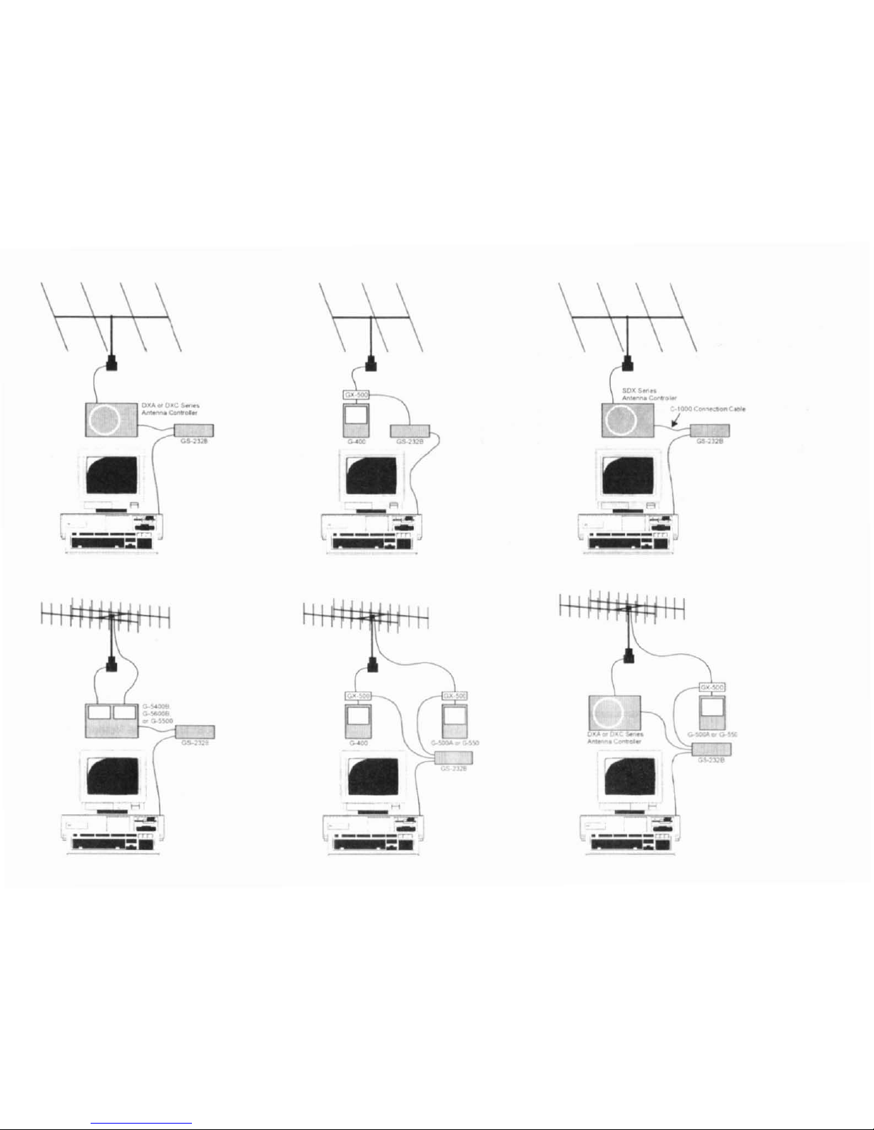
Please read this lIlanual carefullytoinstall the
GS-232B.
Ifalso installing a G-400,
G-SOOAorG-SSO
with
the
GX-
500
Automatic Control Adapter, follow
the
procedures
in
the
GX-SOO
manual before installing the
GS-232B.
x
G-800DXA/G-1
000DXAlG-2800DXA
Azillluth
Rotator.
G-800DXC/G-1000DXC/G-2800DXC
Azillluth
Rotator.
G-400
Azimuth
Rotator.
G-SOOA/G·SSO
Elelation
Rotator.
G-S400B/G-S600B/G-SSOO
A7-El
Rotator.
and
ahmc
A/imuth
and
Elc\ation
rotator
combination.
G-400
Azimuth
Rotator
and
G-SOOA/G-SSO
Ele\
ation
Rota-
tor
requires
olle
GX-500
Automatic
Control
Adapter
each.
1
en
Z
o
-
~
u
-
...
-
U
Lol
C-
OO
2
GE
ERAL
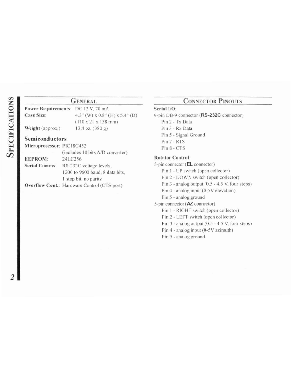
Po\\cr Requirements: DC12V.70mA
Case
Size: 4.3" (W) x 0.8'"
(H),
5.4"
(D)
(110x21x138
mill)
Weight (approx.): 13.4 oz. (380 g)
Semiconductors
M
ieroproeessor:
PIC 18C452
(includes
10
bits
AD
eomener)
EEPROM:
24LC256
Serial Comms: RS-232C
voltage
le\'els.
1200 to 9600 baud, 8 data bits,
1stop bit, no parity
Overnow
ConI.: Hardware Control (CTS
pan)
CONNECTOR
PINOUT
Serial
I/O:
9-pin DB-9 connector
(RS-232C
connector)
Pin
2 - 1x Data
Pin
3 -RxData
Pin
5 -
Signal
Ground
Pin
7 - Rl S
Pin 8
- T
Rotator
Control:
5-pin
connector
(El
connector)
Pin I -UPswitch (open collector)
Pin 2
- DOW switch (open collector)
Pin
3 - analog output (0.5 - 4.5V.four steps)
Pin
4 - analog input (0-5V elevation)
Pin 5
- analog ground
5-pin
connector
(AZ.
connector)
Pin 1 - RIGHT
s"itch
(open collector)
Pin 2
- LEFT switch (open collector)
Pin
3 - analog output (0.5 - 4.5V.four steps)
Pin 4
- analog input (0-5V azimuth)
Pin
5 -
analog
ground
SUPPLIED
ACCE
SORIES
o Control
cable
for
the
Azimulh
Rotator
X1
I
pc
("'5-pil1" -
"Mill-DIN"
cablc)
o Control
cable
for
the
AziEL
Rotator
x
:!
_ I
pc
("'DlIal 5-pil1" -
"DIN"
cable)
o
DC
cable
w/coaxial plug I
pc
o llook &
loop
fasteners
(for mounting) I
pc
x I: G-800DXA. G-1000DXA. G-2800DXA,
G-800DXC, G-1000DXC,
al1d
G-2800DXC
X2: G-5400B, G-5600B,
and
G-5500
AVAILABLE
OPTIONS
GX-500
COl1trol
Adaplcr
(Check wilh
YOllr
dealer)
C-1000
COl1l1ecliol1
Cable
(for SOX
series
Azuirnuth
Rotator)
NC-72B/C/F/U"
AC
Ada
pier
x3:
"B"
suffixisfor
use
wilh
117
VAC,
"C"
suffixisfor
lise
with 220-240
VAC,
"F"
suJJixisfor
lise
willl 220 VAC, or
"U"
suffixisfor
use
with 230 VAC
3
During installation. a
personal
computer
\\ilh
a
serial
POfl
and
terminal
softwareisrequiredtocalibrate
trimmers
on
the
COlltroller
andonthe
Control
Intcrf..,cc.
An) simple
in-
teractive terminal
program
canbeused
-itanI)
hastotrans-
mit
keystrokesaslyped,
and
display
characters
received
from
the GS-232B.
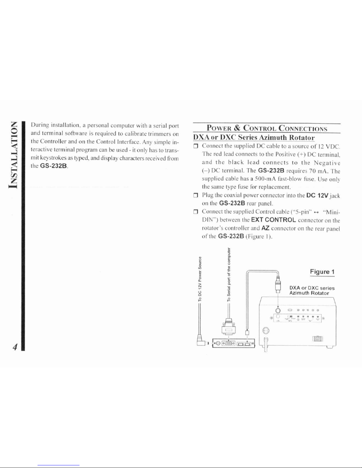
POWER
&
CONTROL
CONNECTIONS
DXA
01'
DXC Series Azimuth
Rotator
o Connect Ihe supplied DC cable
10
a sourceof12
VDC.
The
red lead
connccts
10 the Posilive
(+)
DC
terminal.
and
the
black
lead
conneCls
10
the
egalive
(-)
DC terminal. The GS-232B requires70mAo
The
supplied
cable has a
SOO-mA
fasl-blow fuse. Use only
the
same
Iype
fuse
for
replacemenl.
o
Plug
the
coaxial
power
connector
into
the
DC
12V
jack
on Ihe GS-232B rear panel.
o Connect the supplied Control cable ("S-pin" -
"Mini,
DIN")
belween the EXT CONTROL
connectoronIhe
rOlalor's
controller
and
AZ
connector
all
the
renr
panel
of
the GS-232B (Figure I) .
4
•
•
i
j
"
5
•
..
•0
[
..
>
:!
..
~
~
l?-
I?-
~
~
Figure 1
OXAorDXC
series
';'
Azimuth
Rotator
6
0:> o
00
0 0
~r
.!
~"'i'!.-:
~~
.",.-
-~l·
10
ii3qf-.--
[[5
r
I)OWER
&
CONTIWL
CONNECTIONS
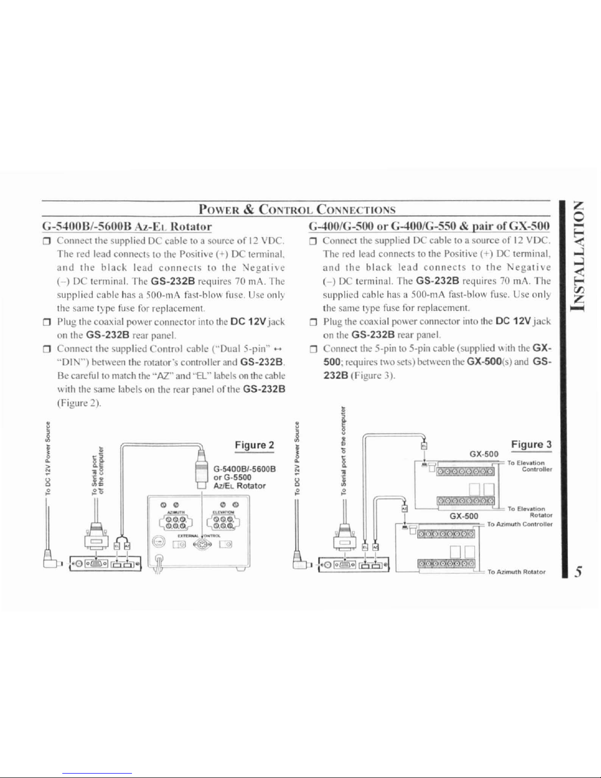
5
Figure
3
j GX·500
",l,tlE'.
~mi~~fiT
ToEI.....
lIlion
(
..•.•..
Controll.,
G-tOO/G-SOOorG-tOO/G-550
& air of
GX-SOO
Connect
Ihe
supphed
DC
cable10a source
of12VDC.
The red lead connects to the Positi\e
(+)
DC
temtinal,
and
the
black
lead
connects
to
the
Negative
( ) D lerminal. The
GS-232B
requires70mAo
The
supplied cable has a
SOO-mA
fasl-blow fuse. Use
only
the
samet)pc
fuse
for
replacement.
Plug the coaxial poll' er connector into the DC 12V
jac~
on the
GS·232B
rear panel.
Connect the S-pin to S-pin cable (supplied \\ith
Ihe
GX·
500;
req""es
1"0
sets) belween the GX-500(s) and
GS-
232B
(Figure 3).
Figure 2
G-S"OOB/-S600B Az-El. Rotator
Connect the supplied DC cabletoa source
of12VDC.
The red lead connects to
Ihe
Positive (+) DC lenninal.
and
the
blach
lead
connects
to
the
\Jegalivc
( ) DC terminal. The
GS-232B
requires 70 mA. 1
he
supplied cable has a
SOO-mA
fast-blowfue.
Use onl)
the
samet)pc
fuse
for
replacement.
Plug the coaxial po\\er connector into
the
DC
12V
jack
on the
GS-232B
rear panel.
Connect the supplied Control cable ("Dual S-pin"
-
"DI")bel\\een Ihe rotator's comroller and
GS-232B.
Be careful to malch the "AZ." and
'"EL"
labelsonIhe
cable
II'
ilh
the same labelsonthe rear panel
oflhe
GS-232B
(Figure 2).
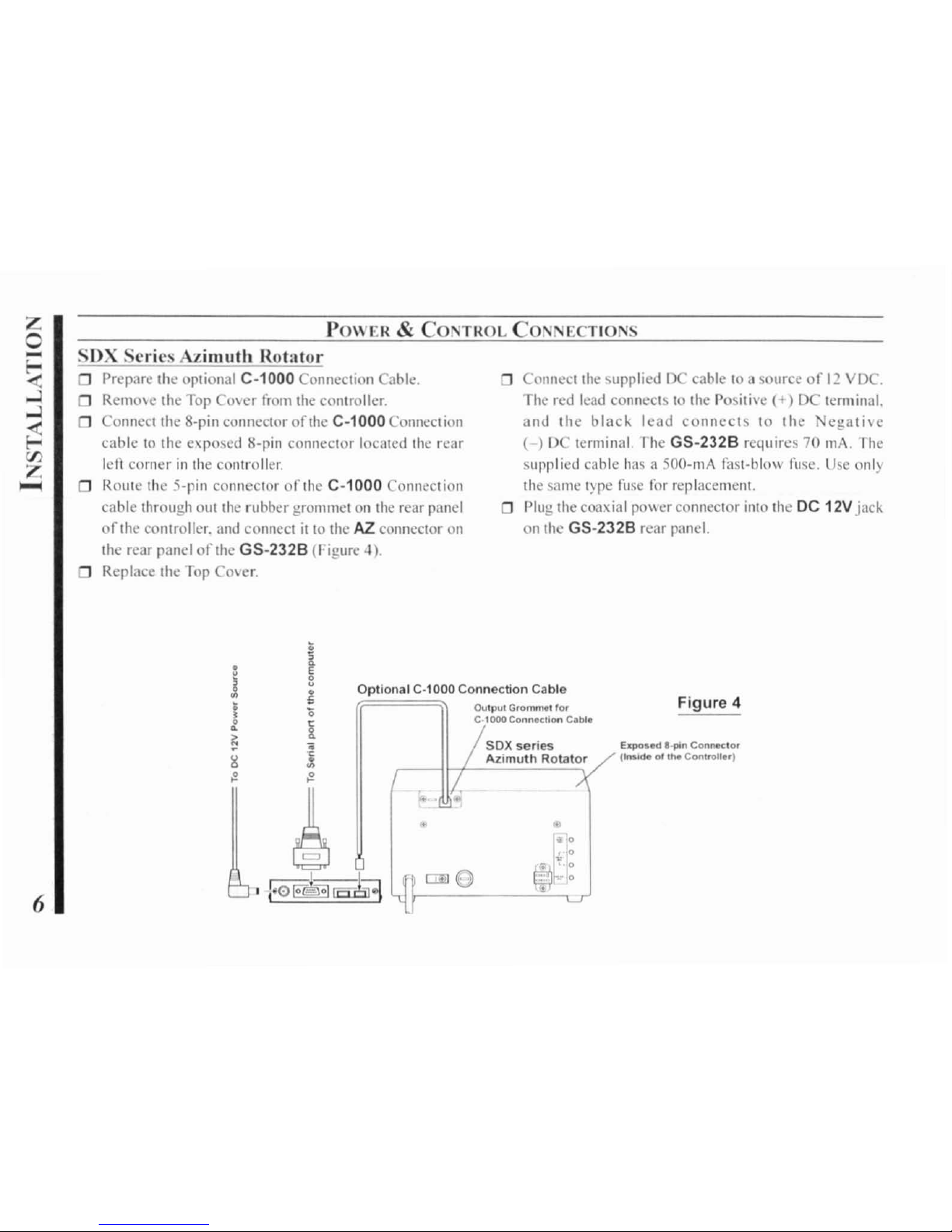
POWER&CONTROL
CONNECTIONS
SDX Series Azimuth Rotator
o Prepare Ihe optional
C-1000
Connection Cable.
Remme
the
Top
Cover
from
the
controller.
o Connect
the
8-pin
connector orthe C-1000 Connection
cabletothe
exposed
8-pin
connector
located
the
rear
left
cornerinthe
controlk:r.
o
Route
the
5-pin connector
or
the
C-1000
ollnection
cable
through
Qut
the
rubber
grommetonthe
rear
panel
of
the controller.
and
connect
illO
the
AZ.
connector
011
the rear panelofthe GS-232B (Figure
4).
o Replace the fop
Cmer.
ConnCCllhe
suppliedDCcable
toasourceof12
VDC.
The
red
lead
connectstothe
Positive
(+)
DC
terminal.
and the
blac"
lead connects
10
the
cgati\c
( ) DC terminal
The
GS-232B requires
70
mAo
1he
;upplied
cable has a 500-mA fast-blo\\ fllse.
Usc
onl)
the
sal1l~
')epe
fuse
for
replacement.
o Plug theconxial po\\ereOnneclOr into the DC 12V
jac~
on
the GS-232B rear panel.
Optional C-1000 Connection Cable
Output GrOmmtl ,~
C·1OOO
Conn.cllon
C.ble
Figure
4
ellposed
a_pin
Confle<:tOf
l~deofI~
Conlroller)
SOX series
Azimuth Rotator
6
 Loading...