

Yaesu G-2000RC Instruction Manual
INSTRUCTION
MANUAL
G·2000RC
\Jï::)
YAESU MUSEN
CO.,
LTD.
\ "I/ / C.P.O.
BOX
1500
vV
TOKYO,
JAPAN

Y
AESU
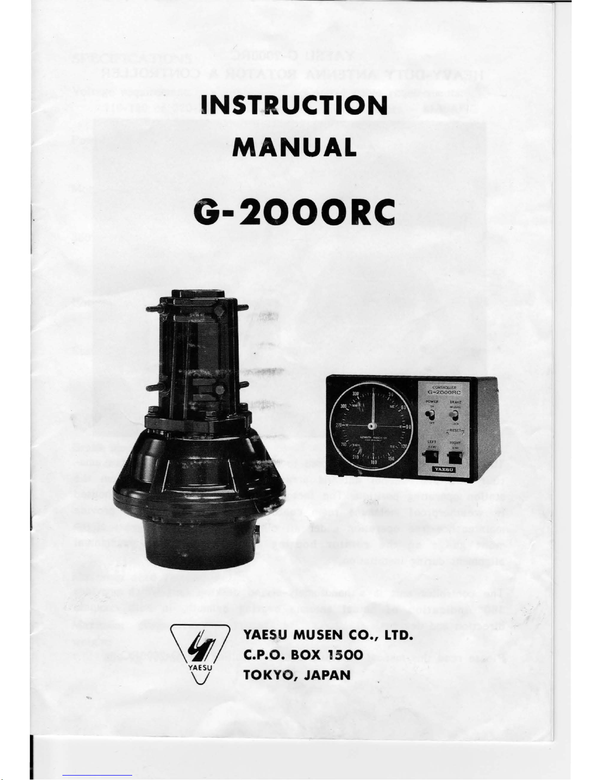
G-2000RC
HEAVY-DUT
Y
ANTENNA
ROTATOR
&
CONTROLLER
The
Yaesu G
-20
00RC is
designed to
support
and
rotate
large-size
ama-
teur
and
professional
antenna
arrays
under
remote
control
from
the
stat
ion op
era
ting p
osition.
The
factory-lubricated
rotator
unit is housed
in
weathe
rpro
of
melamine
resin
coated
die-cast
aluminum, to
provide
maintenanc
e-free
operation
under
ail
climatic
conditions.
A
mast
align-
ment
gu
age
on
the
rotator
housing
simplifies
accurate
mechanical
alignment
dur
ing
installation.
The
cont
roller
unit is a
handsomely-styled
desktop
unit
which
provides
360°
indication
of
actual
antenna
bearing
azimuth, in
both
compass
direction
and
degrees.
Please read
this manual
carefully
before
installing
the
G-2000RC.
- 1 -
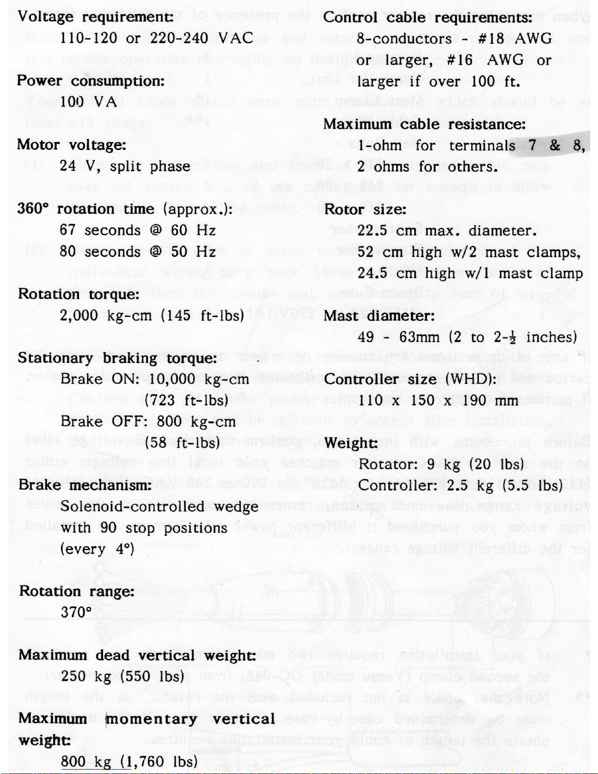
Voltage
requirement:
110-120
or
220-240 VAC
Power
consumption:
100 VA
Motor
voltage:
24
V,
split
phase
360°
rotation
time (approx.):
67
seconds
@ 60 Hz
80
seconds
@ 50 Hz
Rotation
torque:
2,000
kg-cm
(145 ft-lbs)
Stationary
braking
torque:
Brake
ON: 10,000
kg-cm
(723 ft-lbs)
Brake
OFF: 800
kg-cm
(58 ft-lbs)
Brake
mechanism:
Solenoid-controlled
wedge
with
90 stop positions
(every
4°)
Rotation
range:
370°
Maximum
dead
vertical
weight:
250 kg (550 lbs)
Maximum
(momentary
vertical
weight:
800 kg (
l,
760 lbs)
Control
cable
requirements:
8-conductors
- #18 AWG
or
larger,
#16
AWG
or
larger
if
over
100 ft.
Maximum
cable
resistance:
!-ohm
for terminais 7 & 8,
2 ohms for
others.
Rotor
size:
22.5
cm
max.
diameter.
52
cm high w/2
mast
clamps,
24.5 cm high w/ l
mast
clamp
Mast
diameter:
49 - 63mm
(2
to
2-~
inches)
Controller
size
(WHO):
110
x 150 x 190
mm
Weight:
Rotator:
9 kg (20 lbs)
Controller:
2.5 kg (5.5 lbs)
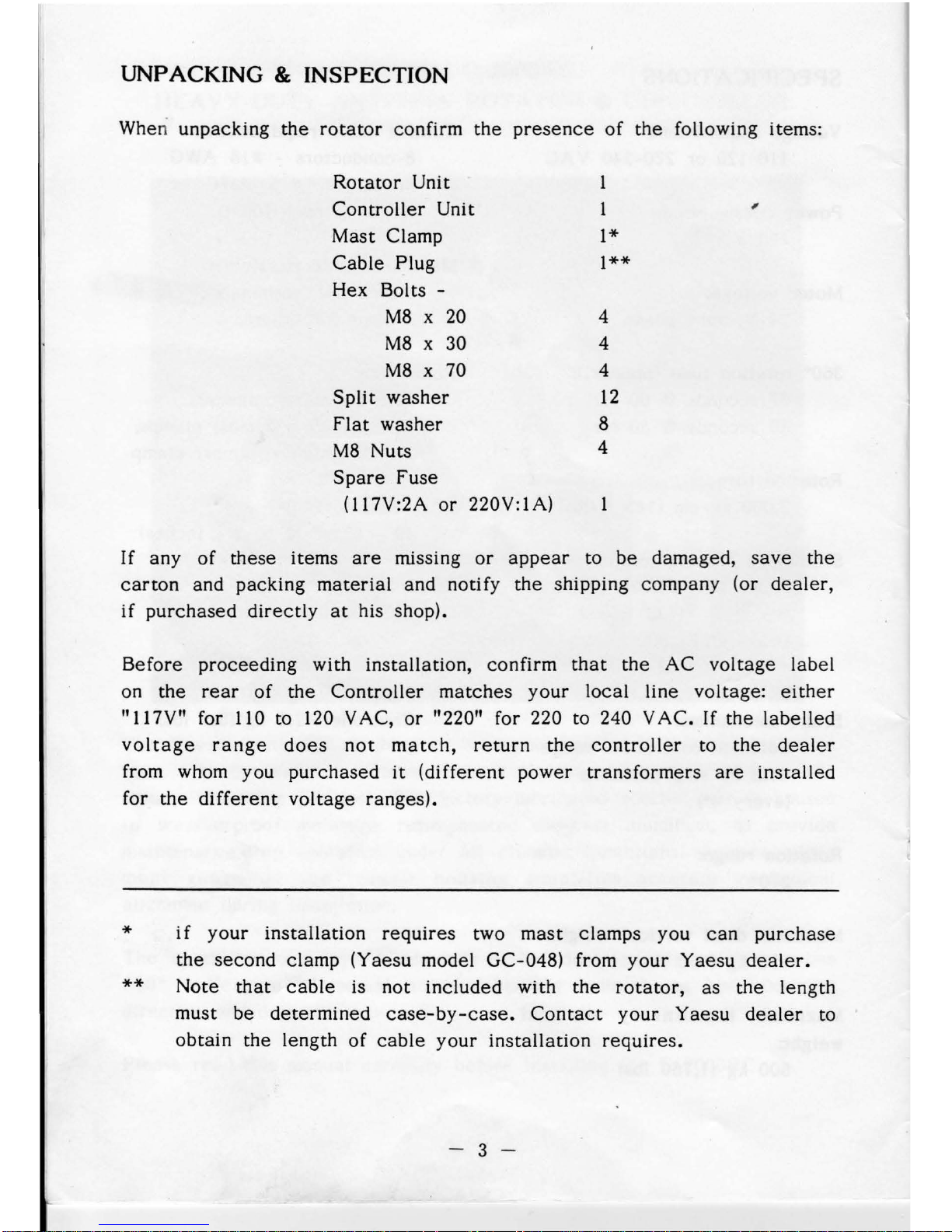
UNPACKING & INSPECTION
When unpacking
the
rotator
confirm
the
presence
of
the
following items:
Rotator
Unit
Controller
Unit
,
Mast Clamp
l*
Cable
Plug
l**
Hex Bolts -
M8
x
20
4
M8
x 30 4
M8
x 70 4
Split
washer
12
fiat
washer
8
M8
Nuts
4
Spare
fuse
(l
l 7V:2A
or
220V:IA)
If
any
of
these items
are
missing
or
appear
to
be
damaged,
save
the
carton
and packing
material
and notify
the
shipping company (or
dealer,
if
purchased
directly
at
his shop).
Before
proceeding
with installation, confirm
that
the
AC
voltage
label
on the
rear
of
the
Controller
matches
your
local line voltage:
either
"l
l 7V" for 110 to 120 V AC,
or
"220" for 220 to 240 V
AC.
If the
labelled
voltage
range
does
not
match,
return
the
controller
to
the
dealer
from whom you
purchased
it
(different
power
transformers
are
installed
for
the
different
voltage
ranges).
*
**
if
your
installation
requires
two
mast
clamps you
can
purchase
the
second
clamp (Yaesu mode! GC-048) from
your
Yaesu
dealer.
Note
that
cable
is not
included
with
the
rotator,
as
the
length
must be
determined
case-by-case.
Contact
your
Yaesu
dealer
to
obtain
the length
of
cable
your
installation
requires.
- 3 -
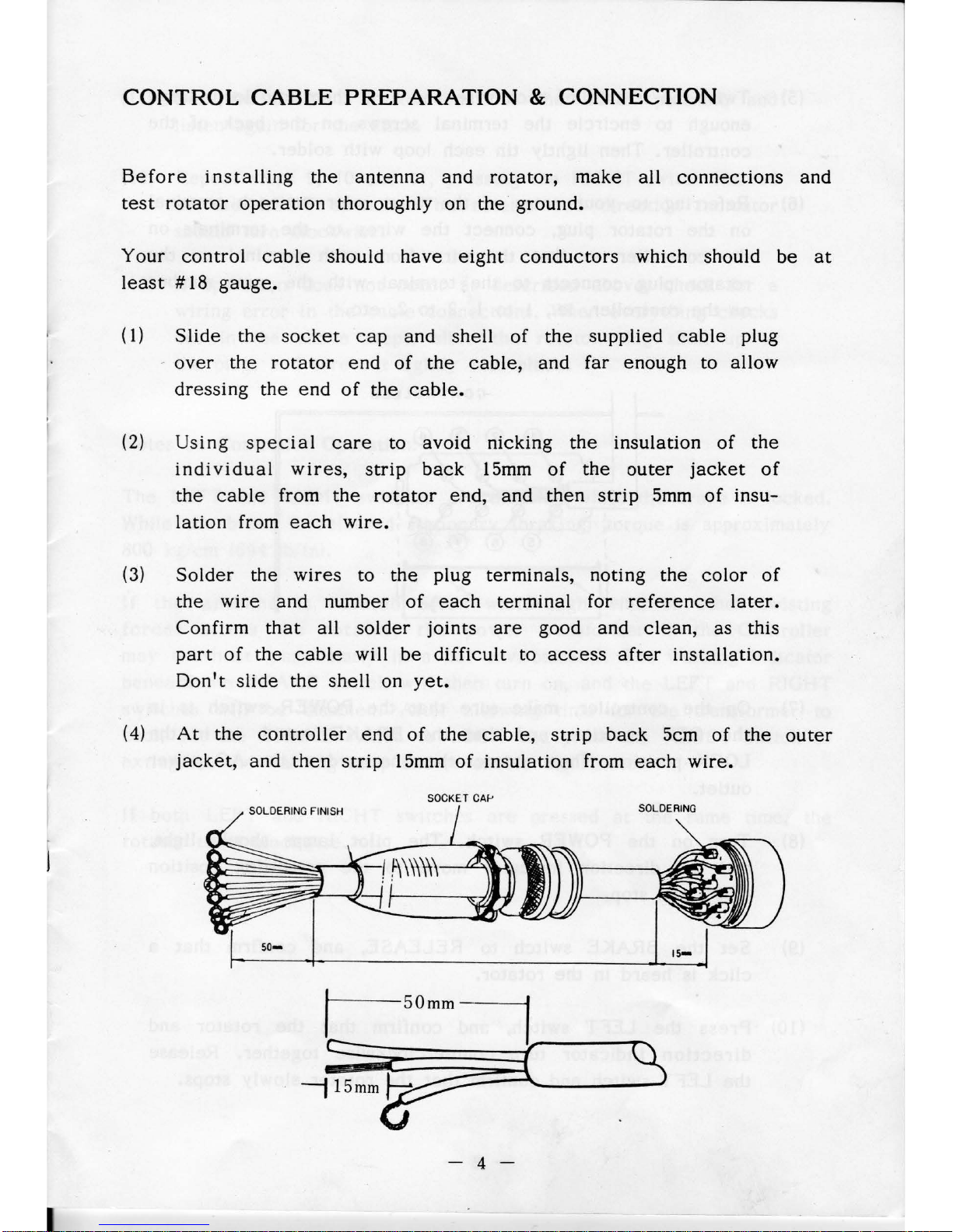
CONTROL
CABLE
PREPARATION & CONNECTION
Before
installing
the
antenna
and
rotator,
make
ail
connections
and
test
rotator
operation
thoroughly on
the
ground.
Your
control
cable
should
have
eight
conductors
which should be
at
least # 18
gauge.
(1)
Slide
the
socket
cap
and shell
of
the
supplied
cable
plug
-
over
the
rotator
end
of
the
cable,
and far enough to allow
dressing
the
end
of
the
cable.
(2)
Using
special
care
to
avoid
nicking
the
insulation
of
the
individual
wires,
strip
back
15mm
of
the
outer
jacket
of
the
cable
from
the
rotator
end,
and
then
strip
5mm
of
insu-
lation
from
each
wire.
(3)
Solder
the
wires
to
the
plug terminais, noting
the
color
of
the
wire
and
number
of
each
terminal
for
reference
la
ter.
Confirm
that
ail
solder
joints
are
good and
clean,
as this
part
of
the
cable
will
be
difficult
to
access
after
installation.
Don't
slide
the
shell
on
yet.
(4)
At
the
controller
end
of
the
cable,
strip
back
5cm
of
the
outer
jacket,
and
then
strip
l 5mm
of
insulation
from
each
wire.
SOCKET CAi-'
so-
- 4
 Loading...