

Yaesu FT-50 Instruction Manual
FT-5OR
Dual-Band Amateur
I I
Hand-Held Transceiver with
Digital Voice Recorder Option

Contents
Description
Accessories and Options
Optional
FTT-12
Keypad
Control and Connectors
Display Indications
Specifications
Before You Begin
Getthg
Started
Basic Operation
Frequency Selection Modes (VFO and MR)
Sub Display Options, Tuning, Transmitting
VFO Duplex Mode
Extended Recption, WFM sql, Auto-Mode select
Rx Mode override, Repeater Operation, T
X
offset
Repeater Shift, Input Track, Input Monitor
Memory Operation
Storing and Displaying Memories,
VFO-k
MR, MR
MR-+VFO,
HOME memory, Custom TX offset, MT
Scanning, Scan Resume Modes, Skip Scan, Lamp
PTS (Preset Tuning and Scanning)
Advanced Operation
Dual Watch (VIM,
M/M,
H/M, V/V)
Naming Memories
Memory Masking
1
3
4
7
9
10
11
73
19
19
20
21
22
23
24
25
25
26
27
28
29
29
30
31
Memory-only Mode, Locking the Controls, TX TOT 32
Tone Squelch Modes (CTCSS, DCS)
33
CTCSS or DCS Bell Paging
34
Tone/Code Scanning, DTMF Code Squelch/Paging 35
Programming/Selecting DTMF Paging Code Memories 37
DTMF Paging Operation (receiving/sending page calls) 38
Trigger Paging, Auto-Respond Paging
39
Paging T
X
Delay, Playback Speed, Paging Bell
40
ARTS (Auto Range Transpond System)
41
ARTS Modes, CW (Morse Code) IDer
42
ARTS Polling Speed, Beeper, DTMF Autodial Feature 43
Autodialer Playback, DTMF Decoder
44
Digital Voice Recorder, Microphone Recording
45
Spkr. Playback, Rx Rec., T
X
Playback, Record Protect
46
VMPS (Voice Mail Paging System)
47
Addendum
49
Extending Battery Life, APO, Rx Batt. Saver
49
T
X
Batt. Saver, Beeper Disable, LED Disable
49
Lamp Illumination Modes, Battery Care
51
Packet Radio
52
Cloning
53
Customizations, MON switch, RV/HM key
54
Appendix
55
Menu FunctionTable, Key Entry Tables
55
The
FT-5OR
compact FM hand-held transceiver provides up to 5 watts of transmitter output on the 2-m
and
70-cm
amateur bands. The optional FTT-12 keypad provides tone systems and digital voice functions, while the standard version includes Digital
Code Squelch (DCS) encoding and decoding,
CTCSS encoding, and a wide range of battery preserving features.
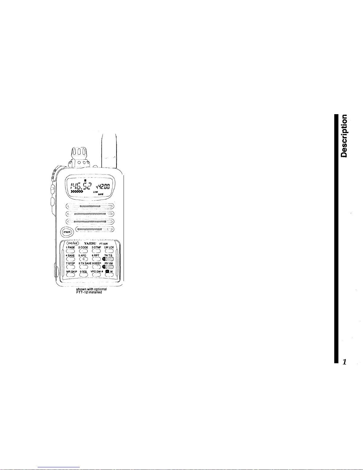
Description
The compact “clamshell” design mounts the
battery
on the rear, for optimum simplicity and portability. A
multi-function knob with concentric volume control
allows setting most functions, minimizing the need
for complex key sequences. The front half of the
case high-impact polycarbonate plastic, while the
transceiver chassis/heat sink is die-cast alloy. A
choice of 4 rechargeable Ni-Cd packs or a dry cell
battery case are available. Rubber gaskets protect
against dust and rain or spray. The LCD (display) has
selectable lighting modes, and shows all significant
frequency digits and most programmable functions,
plus relative signal strength and power output.
Two independent VFOs and up to 100 freely tunable
memories are programmable from the knob and keypad. The duplex mode allows split VFO operation,
and dual-watch monitors a sub-channel VFO or
memory while operating from the main channel.
USA versions include extended reception in the VHF,
UHF, FM broadcast, and 800 MHz bands (cellular
blocked). A separate squelch and bandwidth setting
is available to enhance FM broadcast reception.
Memory features include independent tx/rx frequencies or programmable offsets, up to five pairs of
subband limits for band scanning, selectable scan
skip for busy channels, scan resume on carrier drop
or after
5-second
pause, and independent instant-re-
call HOME channel for VHF and UHF. Memories also

store tuning steps, tone selections, and transmit
power level. Standard channel steps from 5 to 50
kHz,
plus l-MHz steps, are available for tuning. You
can assign 4-character names to memories.
Also include is a DCS encoder/decoder (104 codes),
and a
39-tone
CTCSS (Continuous Tone-Coded
Squelch System) encoder. The DCS system (and
CTCSS decoder provided with the optional FTT-12
keypad) can be set to sound an alert tone when a
selective call opens the squelch. Also, the
FT-5OR
can scan a received carrier and determine if a
CTCSS tone or DCS code is being used, and display
that tone/code.
The ARTS (Auto Range Transpond System) uses
DCS signalling to poll another station to indicate
when they are within or out of range, and can auto-
matically ID with your
callsign
in Morse code every
five minutes.
In addition to the
4-step
power output selection,
unique features to extend battery charge life include
a battery saver which optimizes save duration according to selectable receiver “sleep” periods TX
Save, which automatically reduces transmit power
during periods of high incoming signal strength; selectable time delay APO (Automatic Power Off), and
continuous or
5-second
display illumination.
The keypad generates DTMF tones during transmission, and up to 8 DTMF autodialer memories can
store 16 digits each for quick playback of commonly
used numbers. A special autodialer memory is
re-
served for decoding and displaying DTMF digits offthe-air.
Also, DTMF-based selective calling and private paging capabilities let you select any of 999 three-digit
ID codes for your transceiver, and then have it stay
quiet until your code is received (from any standard
DTMF-equipped transceiver).
Upon
receiving the
DTMF ID code, you can have a paging beeper sound
(1,
3, 5, 8 times, or repeating). In the paging mode,
your display shows the DTMF ID code of the calling
party. Nine 3-digit code memories store your ID plus
those of eight other stations or groups you wish to
monitor, and an extra code memory always stores
the last 3-digit DTMF code heard.
With the optional FTT-12 keypad installed, the trans-
ceiver also provides 20 seconds of voice recording
from the microphone or receiver, for playback
through the speaker or the transmitter. Voice record-
ing can be activated manually or by an incoming
signal.
VMPS (Voice Mail Paging System) combines the
capabilities of both digital recording and DTMF pag-
ing to provide automated response to stations calling
you while you are away. The FT-50R allows calling
stations to leave a voice message, then answers with
your stations CW ID, followed by a pre-stored voice
message (that you record).
Please read this manual carefully to familiarize your-
self with the transceiver’s features,

Accessories & Options
Keypads
FTT-11 (supplied as standard)
FTT-12 DTMF Keypad with Digital Recording,
CTCSS decode, and DTMF paging and DTMF code
squelch
Rechargeable
Ni-Cd
Battery Packs
FNB-40 6.0 V, 650 mAh
FNB-41 9.6 V, 600 mAh
FNB-42 9.6 V, 1100 mAh
FNB-49 6.0 V, 600 mAh
Ni-Cd
Battery Chargers
NC-50 Dual-Slot Rapid Charger
CA-l 4 Charger Sleeve (required w/NC-50)
NC-GOB/C Compact
15-Hour
Charger
(‘B’ suffix for 117-V AC, ‘C’ suffix for 234-V AC)
Other Accessories
FBA-15 Battery Case for 4 AA-size Dry-Cells
CSC-68 Soft Case for FBA-15, FNB-41
CSC-69 Soft Case for FNB-40
CT-27 Cloning Cable
CT-30 Microphone Adapter
E-DC-5B Cigarette Lighter DC Power Cable
E-DC-6 External DC Power cable
MH-34B4B Speaker/Microphone
MH-37A4B Earpiece Microphone
PA-l 7 Battery Cable Extender
RH-1
Rubber Case Protector
VC-23 VOX Headset
CN-3 BNC -to- SMA Adapter
Availability of accessories may vary: some accessories
are supplied as standard per local requirements, others
may be unavailable in some regions. Check with your
Yaesu dealer for changes to the above list.
FTT-12 Keypad
_.__-----
-
-.
FT-SOR
DUAL
1‘
BAND
4 SAVE
5AP0 6 RPT
cm>
co>
cl
7 STEP
6 TX SAVE
9 BEEP
c j c j
c3
I
MR
SKIP+
OSQL VFO DW
#
Cl Cl
c-1
---- -
.-I--..-
FTT-12
FTT-12
ONLY
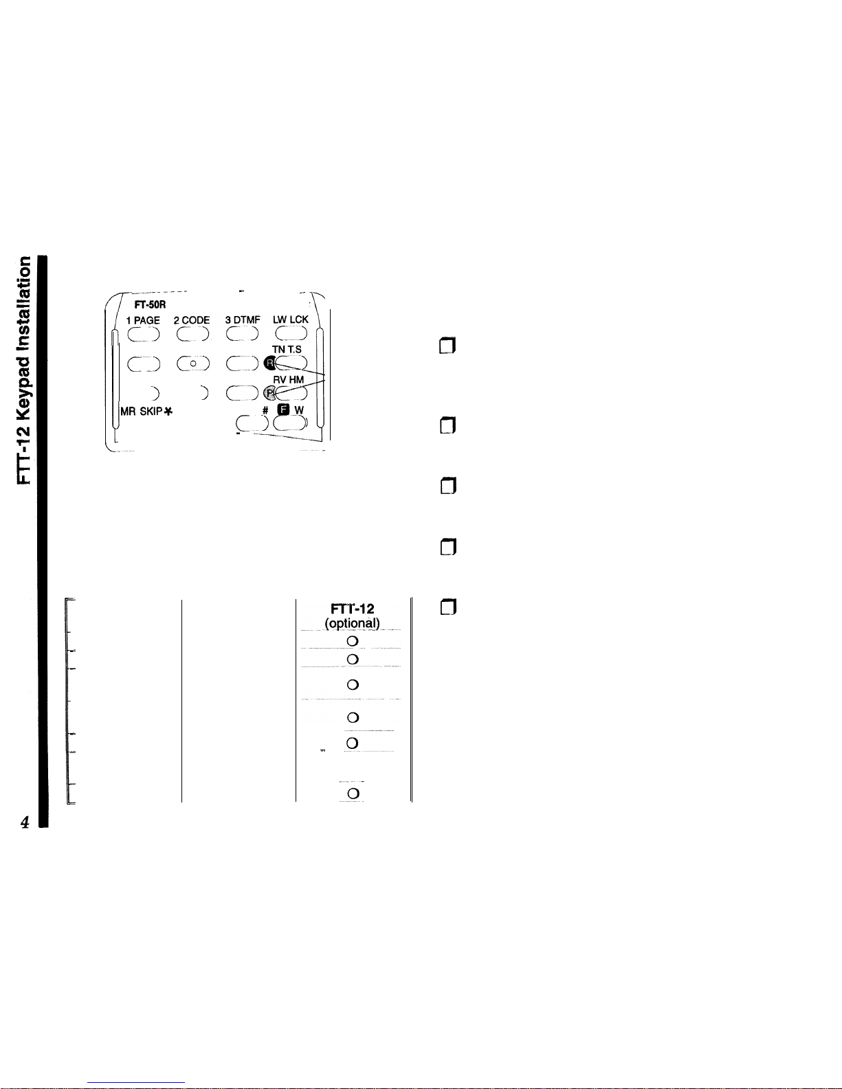
The optional
FTT-12
keypad offers additional transceiver functions, as shown in the chart below. See
your Yaesu dealer for pricing and availability.
Functions
_
DCS & ARTS
Tone Encoder
-
bTMF Encoder
-S,
DTMF Memory
Direct Frequency
_ Entry (keypad)
I
CTCSS Decode
DTMF Code
Squelch
1
Digital Recorder
FTT-1
1
(standard)
0
0
0
0
-
.o----
0
~.,Jy
Installation
The FTT-12 keypad kit includes a keypad, rubber
gasket, Ni-Cd recycling label, and small Phillips
screwdriver:
0
Turn the radio off, and remove the battery. Peel off
the black Ni-Cd information seal, and loosen (but
do not completely remove) the two screws on
either side of the slot behind the original keypad.
m
From the rear, carefully press on both screws with
both thumbs to eject the keypad slightly, then remove the screws to free the keypad.
m
Gently but firmly press the new keypad into place
on the front of the radio, ensuring an even gasket
seal around the keypad periphery (no “pinching”).
m
Replace the two screws removed from the slot
behind the keypad, making sure the keypad and
gasket fit evenly, without pinching.
m
Affix the new
NiCd
label and replace the battery.

Batteries & Chargers
The FT-50R requires the FNB-41 or FNB-42
9.6~volt
rechargeable
NiCd
battery packs for full
5-watt
transmitter power output. However, where slightly
lower maximum power output is acceptable, the
6volt FNB-40 and -49 Ni-Cd packs offer smaller size
and lighter weight. Any
NiCd
pack should be fully
charged before it is used with the transceiver for the
first time.
Two types of battery chargers are available: the
NC-60 K-hour compact charger and the NC-50
Rapid Charger (used with CA-14 Charge Adapter).
The NC-60 is available with a “B” suffix for operation
from 117-V AC, or with a “C” suffix for operation from
220-234-V AC.
NC-50 Dual-Slot Rapid Charger
This AC mains battery charger features rapid and
trickle charging modes for all FNB Ni-Cd packs. It
requires the CA-14 Charger Sleeve for the FNB-40,
-41, -42, and FNB-49, and comes wired for the mains
voltage in the area sold.
The rapid mode automatically brings the battery pack
up to full charge as fast as safely possible using a
peak voltage sensor. A red LED lights during rapid
charging, and when the pack approaches full charge,
the charger reverts to trickle mode (green LED), to
prevent self-discharge. The rapid mode recharges a
fully-discharged battery in about one hour.
FBA-15 Dry-Cell Battery Case
The FBA-15 dry-cell battery case uses four
“AA”-size
(UM-3) batteries. Maximum power output is about 2
watts VHF, 1.5 watts on UHF. Use alkaline cells for
best performance. For ease of battery installation,
insert the + end in first, then press the
-
end so that
the battery “snaps” into place. Note: the lower single
battery can be ejected by pulling upward on the thin
strip.
Caution! The FBA-15 must not be used with rechargeable cells. It lacks the necessary thermal and
over-current protection circuits provided in the FNB
series Ni-Cd Packs.
One or more of the above battery packs/cases may
be supplied with the transceiver. If you need a battery, contact your Yaesu dealer. We do not recom-
mend using any other type of battery, and doing so
may affect your warranty.
Battery Removal & Replacement
m
Make sure the power is switched off, and remove
the protective soft case, if used.
m
Hold the radio face down in your left hand, and with
your right hand, press the Battery Release button
behind the antenna jack while sliding the battery
down
1/4
inch. Then lift the battery away.
To open the FBA-15 battery case, hold it in your right
hand, inside up, and slide the release catch upward
while slipping your left index finger under the notch
to the left of the release catch to lift the panel. Always

replace all four batteries, paying attention to the
polarity indicated inside the case.
To replace the battery case panel, align the two
notches at the bottom edge first, then press the top
edge into the case.
Do not attempt to open any of the rechargeable
Ni-Cd packs, and do not install rechargeable cells in
the FBA-15, as they could explode if accidentally
short-circuited.
VC-23 VOX
Headset
The VC-23 connects to the
MIC/EAR
jack on the right
side of the radio. It consists of a headband-supported
earphone and attached boom microphone, allowing
hands-free VOX (voice-actuated transmit) operation
with the transceiver. For further details, refer to the
VC-23 Operation Manual.
Other Accessories
MH-34 Speaker/Microphone
The Speaker/Mic can increase operating convenience and extend communications range. It includes
a 4-contact plug which mates with the
Mic/Ear
jack
on the right side of the transceiver, disabling the
internal speaker whenever the plug is inserted. The
cable lets you clip the transceiver to your belt, or hold
it above obstructions for better coverage.
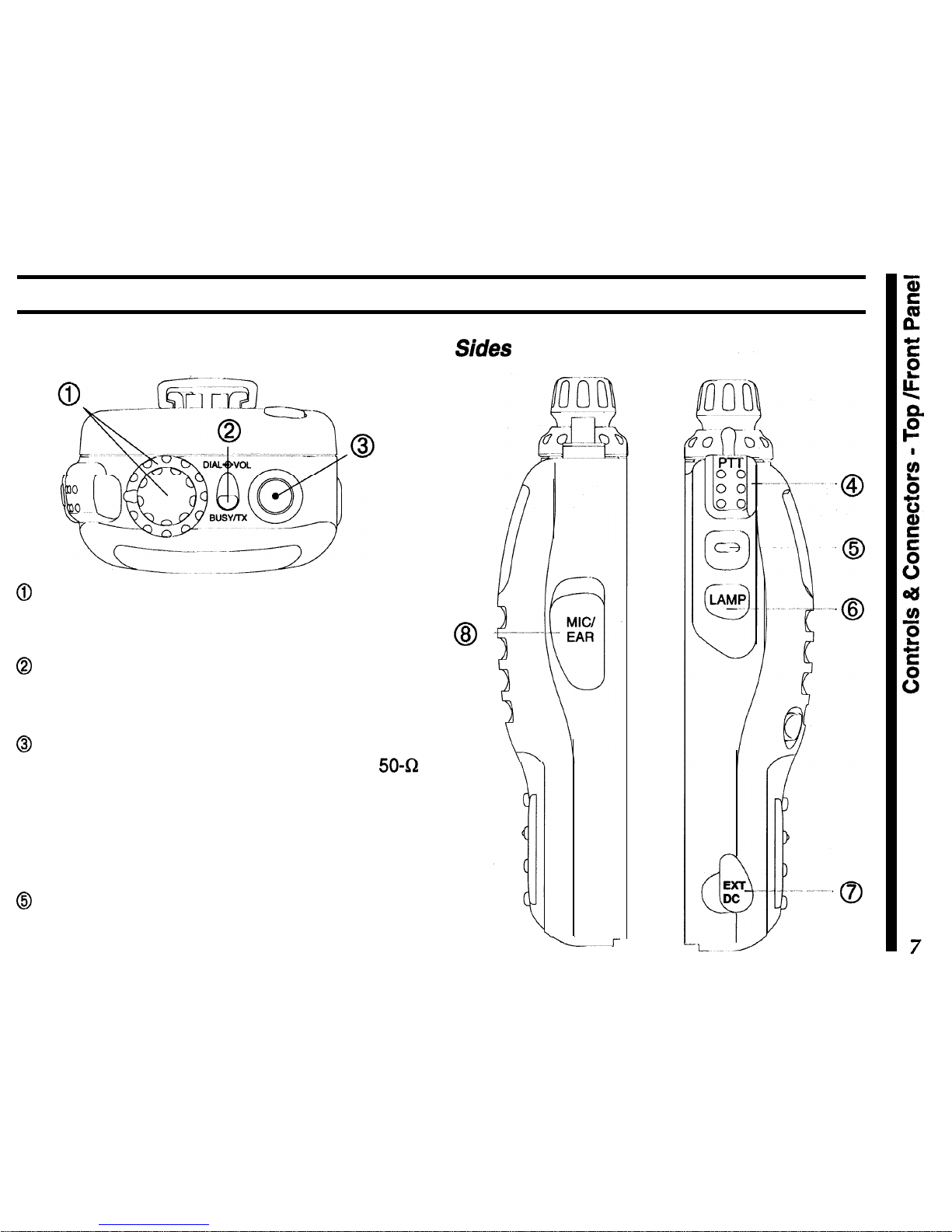
Controls & Connectors
TOP
& Front Panel
@
The outer ring adjusts receiver volume, and the
inner knob tunes, selects memories and other
menu
functions and settings.
@
This LED glows red when transmitting, and green
when the noise squelch is open (channel busy) during reception.
@
This SMA jack accepts the supplied flexible antenna, or another antenna designed to provide
50-52
impedance on the 2-m and
70-cm
band.
@The upper PTT (Push-to-Talk) button activates the
transmitter. Hold this button while speaking across
the front of the radio to transmit.
@
Press this button to override the squelch, either to
set the volume, or to defeat tone squelch temporarily
so you can hear weak or all signals.
@
-
L.--r
8
The (lower) LAMP button illuminates the display
when operating in the dark.
@
This
4-mm
coaxial jack accepts 5-13 VDC at
2A,
via the E-DC-5B cable, to power the transceiver from
an external supply. We recommend using this jack
only with the optional cable.
@
This Q-conductor,
3.5-mm
mini phone jack provides 8-R audio output and accepts microphone input
(2-kQ) for using an optional earphone,
speaker/mic
or packet tnc. The internal loudspeaker
and microphone are disabled when this jack is used.
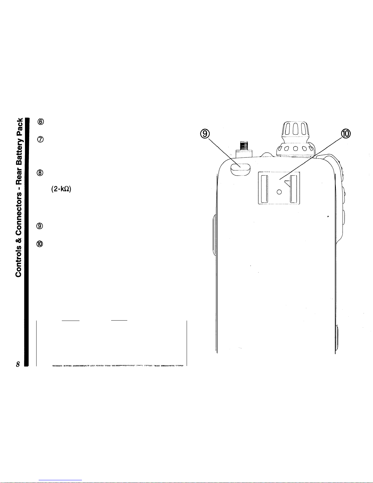
Rear (battery pack installed)
8
Press this button to release the battery for re-
moval.
@
Install the latch-on belt clip here.
Note:
the protective rubber covers over the EXT DC
and Mic/Ear jacks must be pressed over them when
not in use, to protect the inside of the transceiver
from dust and water.
_~-~ _-_
_-.“--l.
._..
--.”
~.“- -“--.-.-x~ -. ._.“.” ._._. ---_.
“.--
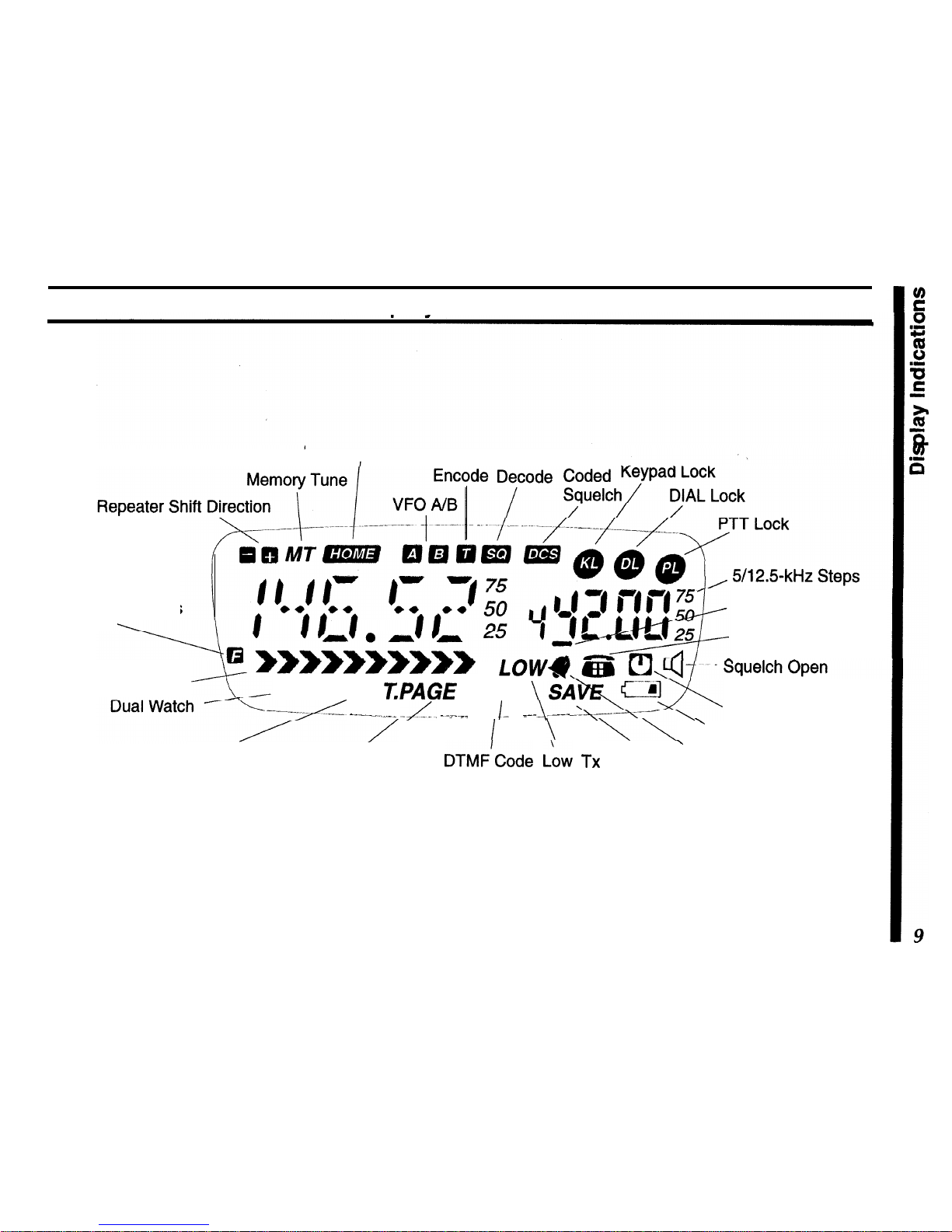
Display
Indications
HoME
Channel CTCSS CTCSS Digital
Alt. Key Functions
Active
Page Code Enable
DTMF Autodial
Rx Signal Strength
LOW
DW SKIP
T.PAGE
CODE
-------yL -..-_-..-_
-/IL,
..,._”
__ I- .
_--
.---
Auto Power Off
I
\
\\
’
Weak Battery Voltage
Memory Scan
Skip
DTMF
paging
DTMF’Code I..~w
TX
Battery ’ CTCSS Bell
Trigger Paging
Squelch
Power Saver

Specifications
General
Receiver
Frequency range (MHz):
Circuit type: Double-conversion
superheterodyne
(transmit)
, (receive)*
Channel steps:
Emission type: .
Supply voltage:
Current consumption:
Antenna (SMA jack):
Case size (WH D):
Weight (approx.):
144 ~ 148,430 ~ 450
IFS:
45.1
MHz &455
kHz
76 ~ 200,300 - 400
Sensitivity:
0.16uV for 12
dB
SINAD
(VHF)
400 ~ 540,590 ~ 999
0.18uV for 12
dB
SINAD
(UHF)
(cellular blocked on 800 MHz)
Adj. ch. selectivity: 65
dB
5, 10,
12.5, 15, 20, 25,
&50kHz
Intermodulation:
65
dB
F2, F3
4~16VDC
AF output:
0.5 W @
81R
(10% THD)
250
uA
Auto Power Off
24
mA
Stby (saver on)
Transmitter
Power output (@ 9.6 V):
approx. 5.0, 2.8, 1, & 0.1 W
200
mA
Rx (approx.)
55
mA
Rx (squelched)
1.5ATx(5
W)VHF
Frequency stability:
Modulation system:
better than lt5 ppm
variable reactance
1.6ATx(5
W) UHF
YHA-58 rubber helical
57x99x30 mm w/FNB-40
355 grams with FNB-40,
antenna, belt clip
Maximum deviation:
*:5 kHz
FM Noise (8 1
kHz):
better than -40
dB
Spurious emissions:
>60 dB
below carrier
AF distortion (@ 1
kHz):
< 5%, w/3.0 kHz
deviation
Microphone type:
2-k&I
condenser
*Specifications are subject to change without notice, and are
guaranteed within amateur bands
on/y.
Frequency ranges and repeater shift vary according to transceiver version, check with your dealer.
Before You Begin
A Few Notes on Safety
When properly cared for, the
FT-S5OR
should provide
many years of operating pleasure. However, please
read the following items concerning its use:
Battery Charging
Rechargeable batteries contain encapsulated
NiCd
(Nickel Cadmium) or
NiMH
(Nickel Metal Hydride)
cells. When used properly, they present no operator
hazard; however, please note the following points:
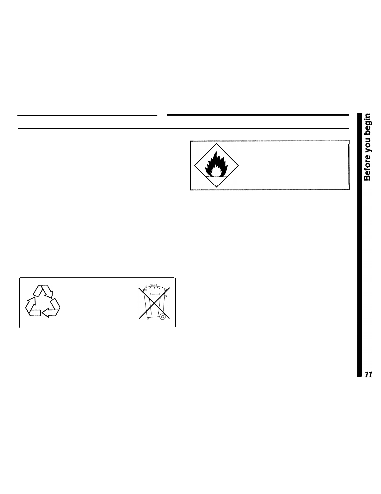
l
Do not dispose of
NiCd
cells in the public waste
system, as this may present a possible soil contamination hazard. Check with your local waste management bureau for recycling programs available in
your area.
ml
Nickel-Cadmium Rechargeable
aa
Battery - do not dispose of into
waste system.
Recycle batteries in accordance
NiCd
with local regulations.
l
Never discard any batteries into a fire!
Never allow the charging terminals on
the battery to short
-
the ceils can be
damaged and the heat generated can
burn the skin!
l
Do not recharge the battery pack with unapproved
chargers.
Modern battery chargers use special circuitry to provide the optimum charge rate and place the battery
in a trickle charge state when complete. The use of
other chargers could possibly damage your battery
pack, and your radio.
l
Never allow the battery charging terminals to short!
While the recessed charging terminal on the battery
pack offers a degree of safety from inadvertent short-
ing, never insert any metallic objects into or across
the terminals. When separating the battery from the
transceiver, never lay it down onto a metallic surface.
The heat generated from a shorted pack can destroy
the cells and possibly burn the hand holding it.
Exposure to Water
While the
FT-50R
utilizes a water-resistant “clamshell” design with rubber o-rings to seal out moisture,
common
sense must prevail...should the radio become exposed to water, use a soft cloth to wipe off
any excess drops.
If for any reason the radio is submersed, do not
turn
it
on...remove
the battery pack, wipe off the excess
water from both the radio and battery, and allow them
to dry at roorn temperature (no forced heat) for several days before powering it on again. If the radio fails
to function, turn it off immediately and contact your
dealer for service information.
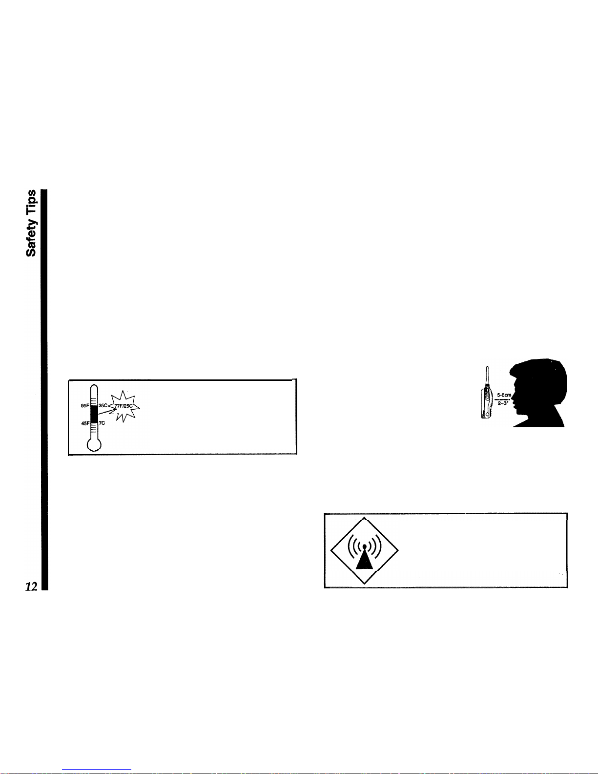
Whenever possible, charge batteries
at close to room temperature. Charging at temperatures below 77F/23C
,can
cause electrolyte leakage and result in battery damage. Charging at
high temperatures (above
95F/35C)
may reduce charge capacity.
RF Radiation Hazard Statement
In 1985, the US. Federal Communications Commission (FCC) adopted a safety standard for human
exposure to Radio Frequency (RF) electromagnetic
radiation generated by FCC-regulated equipment.
The proper use and operation of this transceiver will
result in exposure to the operator substantially below
those limits recommended by the FCC. However, the
following tips are recommended for maximum operator safety:
l
Do not press the PTT (Push To Talk) switch unless
you actually desire to transmit.
l Hold the transceiver a few
inches from your mouth when
transmitting, so that the antenna is not in direct contact
with your face or eyes.
l When not using the trans-
ceiver, store it in a safe place, out of the reach of
children.
l
Do not operate any transmitting equipment near
unshielded blasting caps!
Do not hold the transceiver with the
antenna touching exposed parts of
the body while transmitting, especially
the face and eyes.
Getting Started
First Steps
Before operating the transceiver the first time:
n
Charge the battery pack completely (if using a
rechargeable pack). If using an FBA-15 dry-cell
battery case, install alkaline batteries as described
on page 5.
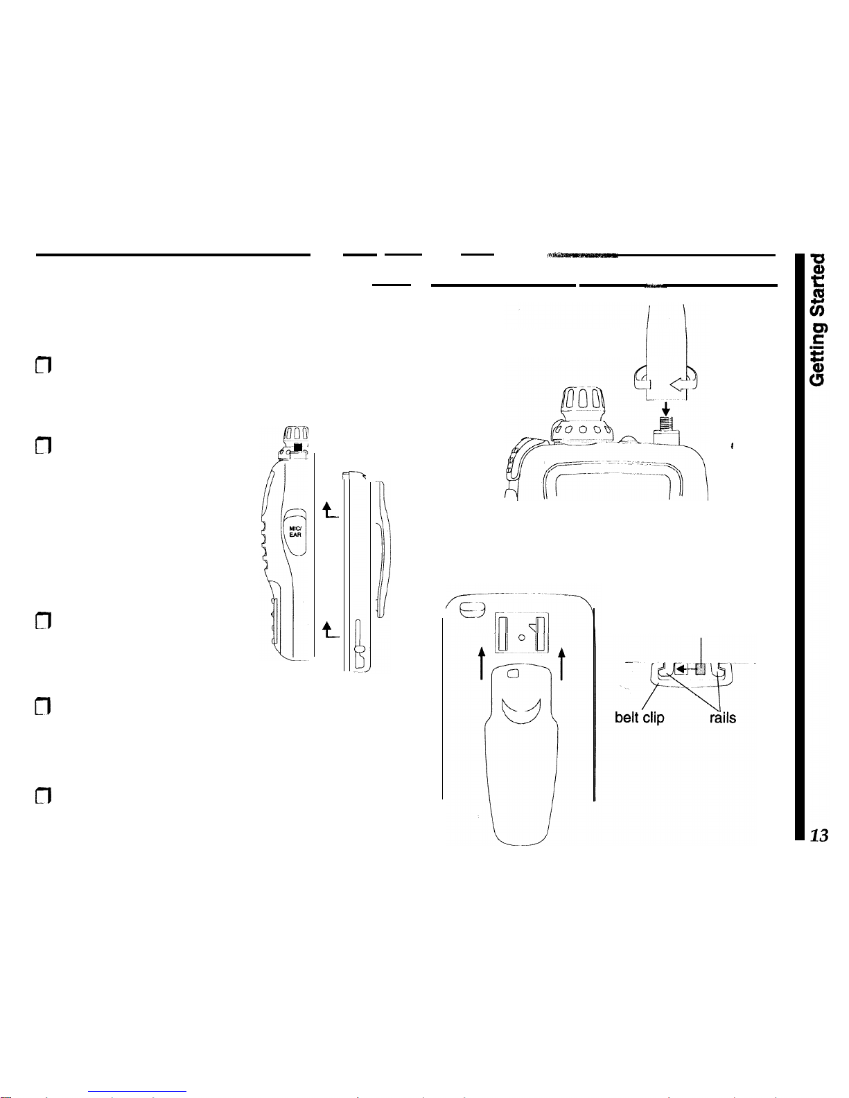
m
Mount the battery pack on
the back of the radio: hold it
with the rounded top edge
1/3
-inch (8 mm) lower than
top,
edge of the radio, press
the four tabs on the battery
into the slots on the radio,
and slide the battery up until
it clicks.
m
Screw the supplied antenna
onto the
antenna jack. Never
operate the transceiver without an antenna connected.
t
t.
-‘t
1
I
n
To install the belt clip, slide it up onto the battery
pack rails until it “clicks” (locks into place). To remove it, slide the release lever to the left, then
press the clip down and off of the mounting rails.
CT)
If you have a
speaker/mic,
we suggest you not
connect it until you are familiar with basic operation.
antenna
installation
belt clip
installation
slide lever left
to release
Powering On
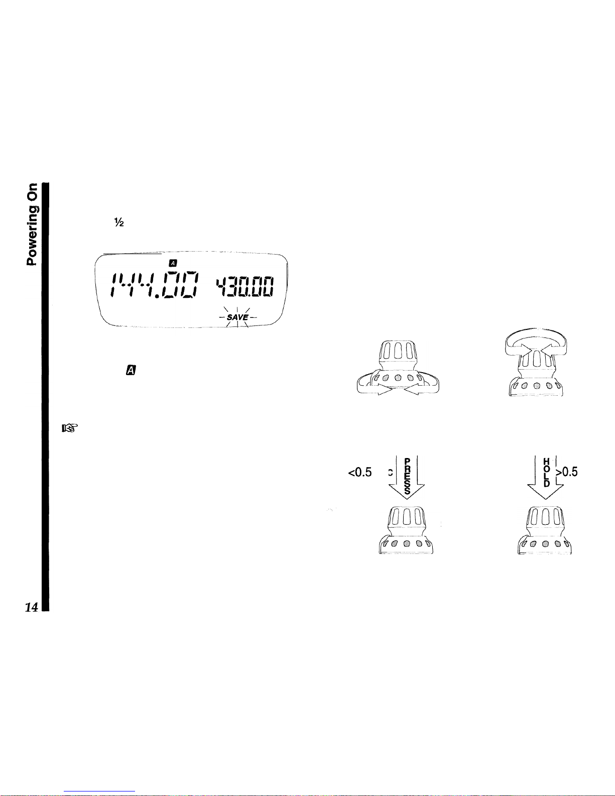
To turn the transceiver on, push in the orange
PWR
button for M second. If the radio has not been used
before, the display should appear like that below.
The larger frequency readout is the
main
channel,
while the smaller one to the right is called the
sub
channel. The 6! symbol indicates which VFO (A or B)
is selected for operation, and the
blinking
SAVE
indi-
cator lets you know that the
battery
saver is enabled
from the factory (we will cover more on this later).
63
When you turn on the radio the first time, you will
hear channel noise, and will
need to set the squelch
/eve/ as explained on the following page.
Knob Functions
Let’s spend a few moments on how the knob functions, as understanding its proper use will make it
easier to operate the rig and configure various features as we continue through the manual.
As shown in the illustration, the lower ring adjusts the
volume. Set it for a comfortable level while receiving
a station, or else press the middle monitor switch
(below the PTT) to disable the squelch, and adjust
the volume level on background noise.
Rotating the knob tunes in the default step size on
the VFO, or else selects programmed memories during MR (Memory Recall) operation.
Pressing the knob
mornentariljl (< 0.5s)
selects the
band of operation.
Holding
it longer recalls the menu
list, from which various transceiver functions are
enabled and their settings are configured.
Lower Ring -
rotate for
volume level adjustment
knob
-
rotate to tune
channels,select
mem-
-ories or menu settings
<0.5 sec
I4
L/J
E
S
knob -
press to switch
bands or view default
menu settings.
H-
~
P
bO.5
sec
D
knob, - hold to recall
the menu function list,
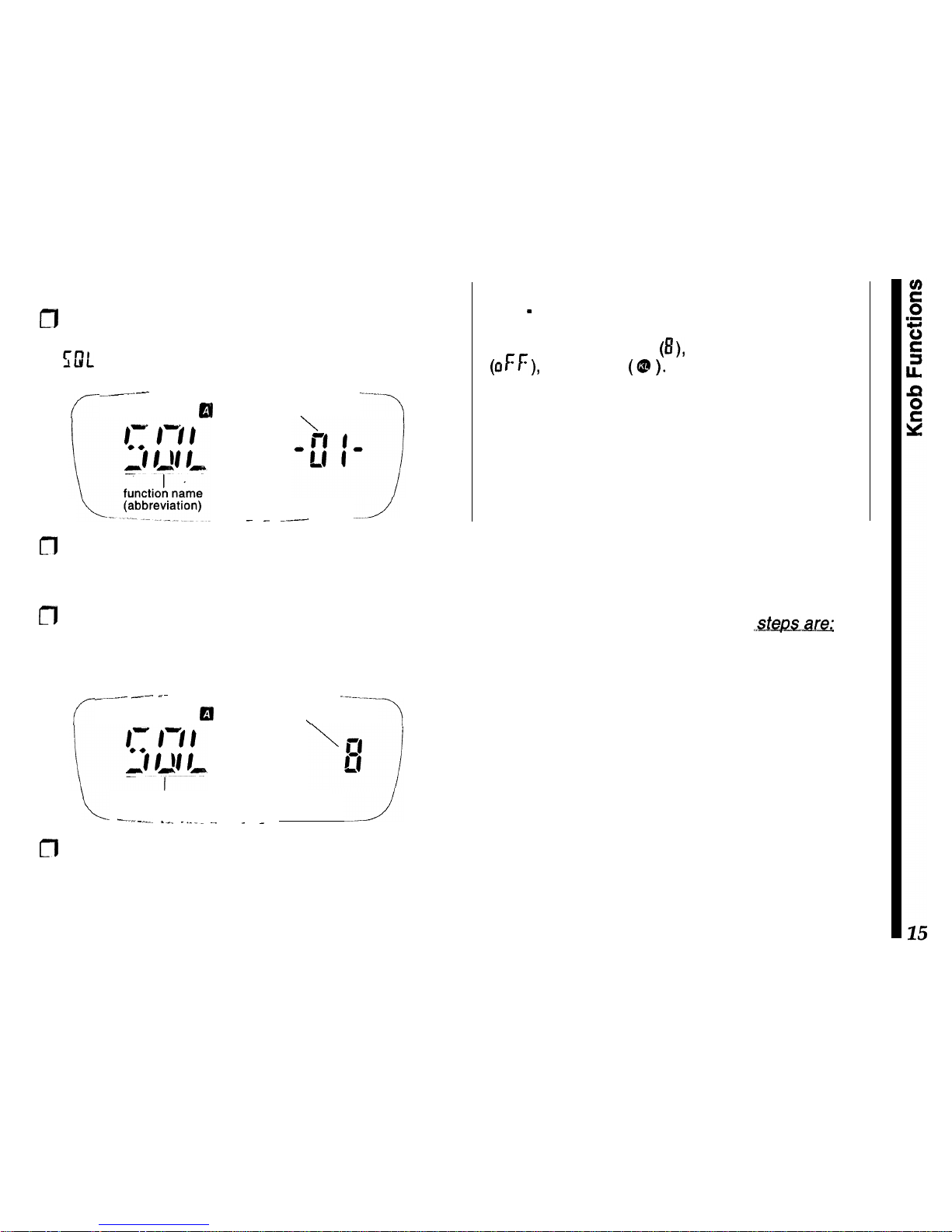
Let’s start by setting the receiver squelch:
a
Hold (> 0.5 sec.) the knob down until the beep
sounds, then turn the knob (if necessary) to select
GIL -or-.
c--
.__I_-
----
or
funqtion #
‘7
SAVE
_ --
__-.
---
m
The name or abbreviation at the left is the function
title, with its number displayed to the right. You can
turn the knob to scroll through all 32 functions.
m
Momentarily pressing the knob shows the default
setting for the displayed function (in this case it is
the squelch level, which ranges from 0 to 15):
r
_~__..._
-~-. -~
1--.-__
El
setting
\
function
L -____._
I_^
._.. ~.
SAVE
_ _
m
Rotate the knob a click or two past the point where
channel noise is muted, then exit the menu list by
simply pressing the PTT (the radio does not transmit). The display reverts to show channel data.
Note - Pressing the knob with a menu active replaces
the function number (at the right in the sub display)
with either a number
(8),
letter or abbreviation
(OFF), or a symbol
(Q? ).
In some cases the function
name (at the left) may also change, to describe the
setting more clearly.
Follow the instructions carefully when starting out,
until you become familiar with the abbreviations and
symbols used with each menu function and its associated settings.
Things to remember...
The procedure just covered is used throughout the
manual to access functions and change settings as
desired. Once again,
the three basic
l
Hold the
knob down to recall the tnenu list, then turn
the knob to select the desired
tnenu
function
(number).
l
Press the knob to display the various function set-
tings or state, then turn the knob to change or select
it as desired.
l
Press the
PTT to
save the change and exit.
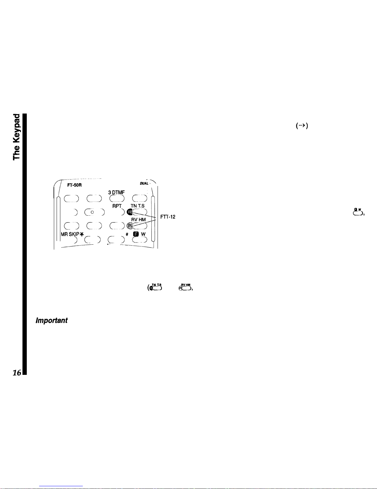
The Keypad
The standard FTT-11 keypad permits quick access
to the most commonly-used transceiver functions.
The optional FTT-12 keypad adds digital voice recording/playback, DTMF code squelch and CTCSS
decode capability.
-- -
\
DUAL
BAND
\
1 PAGE 2 CODE
BDTMF
LW LCK
cjc.~c~c~
4SAVE 5AP0
6 RPT
c 1
CL I
c
I
7 STEP 8 TX SAVE 9 BEEP
Cl
Cl
Cl
MRSKIP+ OSQL VFODW
c I c > c-
I
-Y
-- -~
,..-
FTT-12
FTT-12
ONLY
Both keypads are similar in appearance, with the
FTT-12 having two additional labels on the pad sur-
face for the digital recording system
(I$!?$
and
fi,
specifically). Throughout the manual, features requiring the FTT-12 are highlighted as such.
important -
Normal key presses should be very
quick -just a tap. Keys, like the knob, are sensitive
to the duration they are depressed. In some cases
tapping a key and holding it ‘longer will activate a
different function, and produce different results and
display indications. The instructions specify when a
key is to be held down.
To indicate when several keys have to be pressed in
sequence, we show an arrow
(-+) between them. Do
not press more than one key at time unless the
instructions say so.
One or more beeps indicate key contact has been
made (if the key has a function). You can disable the
beeper as described later, but we recommend keeping it enabled while getting to know the key functions,
since the pitch and number of beeps can be useful
feedback.
A several-second timer starts when you press
&,
and automatically restarts when you turn the knob.
Pressing other keys may shut off the timer as the
resulting change in operation occurs, or restart the
timer so you can select various functions.
Also, after changing a setting, you can usually return
to the operating frequency display by pressing the
PTT button at the top left corner of the radio. It does
not transmit unless the operating frequency is displayed. The front keypad generates standard DTMF
tones when pressed while transmitting.
While reading about operation, if you are unsure
about the location or function of a button or display
item, refer to Controls and Connectors and Display
sections on pages 7 and 8.
Your first
QSO
Adjusting the Volume
0
Turn the outer ring of the knob on the top panel
control to adjust the volume. If there is no signal,
you can override the squelch by holding the center
button (on the left side below the PTT switch), to
set the volume on background noise.
Squelch Setting
m
To adjust the squelch, hold the knob down for
%
second,
then turn it, if necessary, so that CDL
-0 I-
is displayed.
m
Press the knob again momentarily, then turn it to
set the squelch threshold (0 to 15) so the receiver
is silenced (the
BUSY/TX
LED turns off). Press the
PTT momentarily when done.
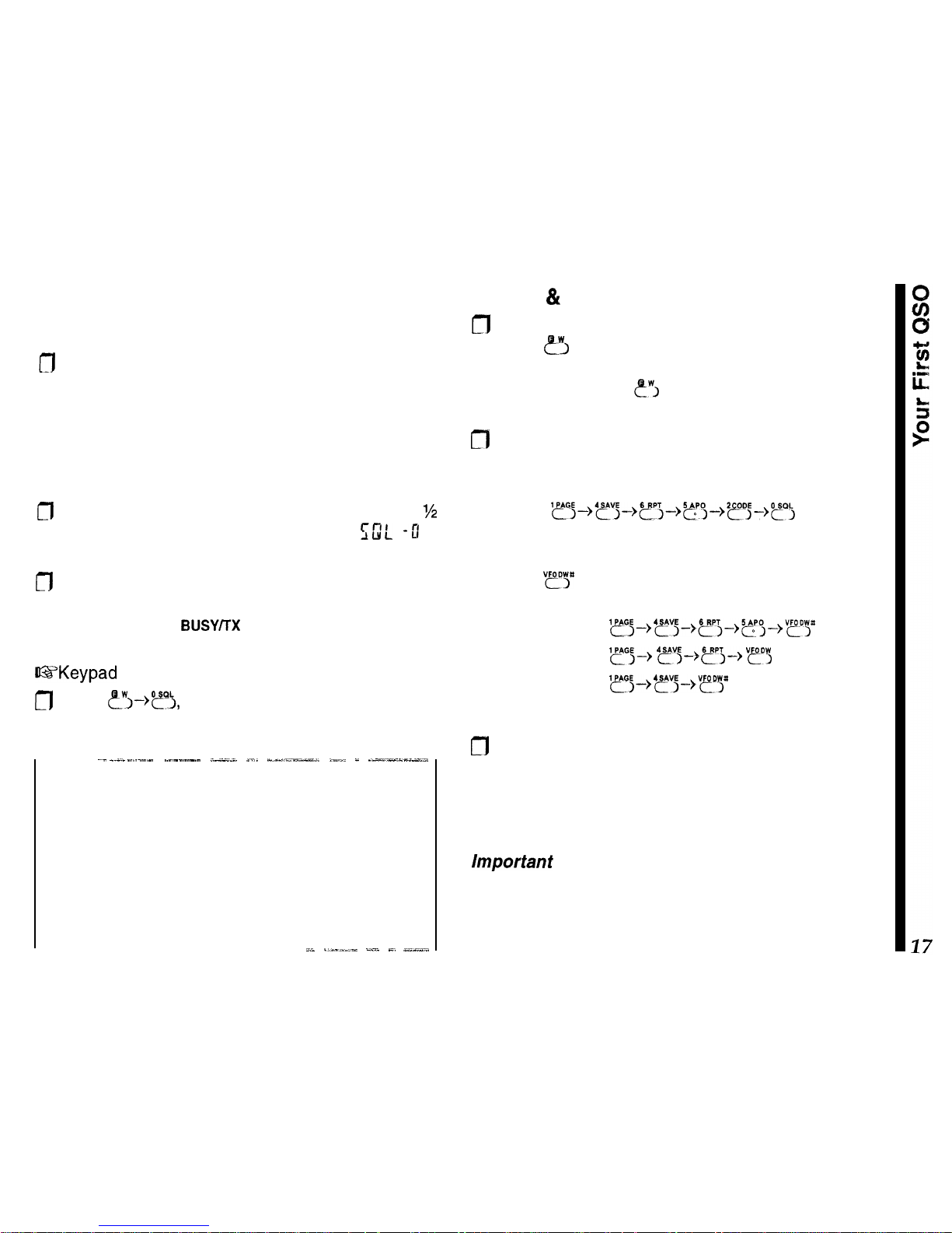
US’Keypad
shortcut for setting the squelch
n
Press
?I->?),
turn the knob to set the squelch
level, then press the PTT to save
and exit.
--~-
_.-._ -.-..-
.----.-- .--;- _... -__,-_l”-_LI-l ,__ _ __-__-___.,
Squelch Sensitivity
First set the volume to mid range, then adjust the
squelch (with no signal): slightly past the point where
background noise is silenced and the green
BUSY/TX
LED is extinguished. If set higher, sensitivity to weak
signals is reduced, if set too low, “falsing” on background noise and weak stations will result.
AL ._-__..- _.~‘. -. _-_-..
Tuning & Direct Frequency Entry
n
Tune to the desired frequency using the inner knob:
press 8 at the lower right momentarily, and turn
the knob to select the MHz range, then wait 5
seconds or press
ewj
again and turn the knob to
select the frequency.
m
You can enter frequencies directly from the keypad
as well; just key in all the digits. For example, for
146.520 MHz enter:
‘~~~-,‘~;-,~~-,~“,-)2~j_)~,
If you want to enter an even whole frequency, like
140.00 MHz or 146.000 MHz, there’s a shortcut,
Pressing
“?“P
after any entry truncates the remaining
digit places to zero:
enter 146.500
l~~~,'~j~,~,~,~pg~,V~pp
enter 146.000
yGj+
4~3+5r3+
vp",
enter 140.000
'~~-->'~j&QPp
Transmitting
cfl
To transmit, wait unit the channel is clear; press the
PTT (Push To Talk) and speak in a normal voice.
Keeping the transceiver a few centimeters from
your mouth will result in best audio clarity. Release
the PTT to receive again.
Important
- The PTT switch should be pressed inward and in a slightly downward direction for proper
operation. Do not press the PTT switch in an upward
direction, as this cause unreliable closure of the PTT
switch, and it may damage the rubber boot.
 Loading...