

Yaesu FT-4XR, FT-4XE, FT-4VR, FT-4VE Operating Manual
VHF/UHF
DUAL BAND FM TRANSCEIVER
FT- 4X
FT- 4X
Operating Manual
R
E

Contents
Introduction ....................................................................................................................... 1
About this manual ............................................................................................................ 1
Quick Guide ...................................................................................................................... 2
Controls & Connections .................................................................................................. 3
Transceiver ..................................................................................................................... 3
Display ............................................................................................................................ 5
The Keypad Functio ns ................................................................................................... 7
Safety Precautions (Be Sure to Read) ............................................................................ 8
Preparation ...................................................................................................................... 11
Instal ling the Antenna .................................................................................................. 11
Attac hing th e Belt Clip ................................................................................................. 11
Instal ling the Batter y Pack ........................................................................................... 11
Removin g the Bat tery P ack ...................................................................................... 11
Supplied Accessories and Options .............................................................................. 12
Supplied Accessories .................................................................................................. 12
Availabl e Optio ns ......................................................................................................... 12
Charging the Battery Pack ............................................................................................. 12
Chargi ng the Bat ter y Pack usi ng the Ra pid Char ger (SBH-22) ................................. 12
Operation ......................................................................................................................... 13
Switching bet ween VFO-A , VFO -B and Memor y mode ............................................. 13
Selec ting the Operating Ban d ..................................................................................... 13
Tuning to a Freque ncy .................................................................................................. 14
Changing the Frequency Step .................................................................................. 14
Adjusting the sq uelch s ettin g ....................................................................................... 14
Transmission ................................................................................................................ 15
Changing the Transmission Power Level .................................................................... 15
Locking Keys and PTT swit ch ...................................................................................... 16
Progra mmable key [P1]/[P2
Repeater Operation ........................................................................................................ 17
Communicating Via the Repeater ............................................................................... 17
Tone Calling (1750 Hz) ................................................................................................. 17
Using the Memory .......................................................................................................... 18
Registe ring to M emor y Chann els ................................................................................ 19
Memory Recall ............................................................................................................. 19
Clearing Memories ....................................................................................................... 20
Recall ing the H ome Channels ..................................................................................... 20
Changing the Home Channel Frequency .................................................................... 20
Memory Channel Scanning ......................................................................................... 21
Setti ng the Rec eive Op erati on When S canni ng Stops ............................................... 21
Split Memory ................................................................................................................ 22
Using Me mor y Tag ....................................................................................................... 22
Using Me mor y Bank ..................................................................................................... 22
Scanning Function ......................................................................................................... 22
VFO Scan ..................................................................................................................... 22
Progra mmed VFO Scan ............................................................................................... 23
Weather B roadc ast Chan nels sc an (In the USA) ........................................................ 23
Weather Alert Scan (In the USA) ................................................................................. 24
Skip Me mory C hannel .................................................................................................. 24
Progra mmable Memor y sca n (PMS) ........................................................................... 24
Dual Rec eive (DW ) feature .......................................................................................... 24
Convenient Functions .................................................................................................... 25
VOX Operation ............................................................................................................. 25
VFO Split Mode ............................................................................................................ 25
Tone squelch feature .................................................................................................... 25
Digit al Code S quelc h (DCS) fea ture ............................................................................ 25
New PAGER (EP CS) feature ....................................................................................... 25
Using Set Mode ............................................................................................................... 26
Tables of Set Mo de Ope rations ................................................................................... 26
Restoring to Defaults (Reset) / Setting the Preferred Operating Mode ..................... 29
Specifications ................................................................................................................. 30
] ........................................................................................ 16
Introduction
Thank you for purchasing this Yaesu product.
FT-4XR/XE is a handheld transceiver for operation in the 144 MHz and 430
m
MHz Amateur radio bands.
A Bridged Transless (BTL) amplifier provides One Full Watt of Audio, in
m
spite of the transceiver’s small size.
Two Quick Recall Keys are User Programmable for Individual Preferences.
m
Lockout Capability for Keypad and PTT.
m
Emergency Operation with Alarm and HOME channel display.
m
A variety of individual selective calling functions; such as tone
r
squelch (CTCSS) and DCS functions ................................................
Large-capacity 200 memory channels .............................................
r
3 home channels and 10 pairs of PMS memory channels ........................
r
Create mnemonic tags for memory channels and PMS channel ......
r
Automatic power OFF (APO) feature turns the transceiver
r
OFF after a preset time period ..........................................................
The cloning feature allows the memory and configuration data
r
from one transceiver to be transferred to another FT-4XR/XE. .........
The VOX system provides automatic transmit/receive
r
switching based on voice ..................................................................
We urge you to read this manual in its entirety, and also the Advance Manual
(available for download on the Yaesu website), to gain a full understanding of
the amazing capability of the exciting new FT-4XR/XE Transceiver.
28
18
20
19
26
29
28
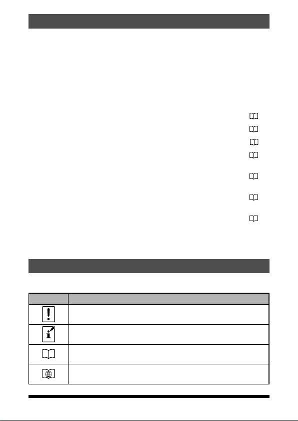
About this manual
Reference icon symbols and conventions are used in this manual. Their
meanings are described in the below chart.
Symbols Description
This icon indicates cautions and information that should be read.
This icon indicates notes, tips and information that should be read.
This icon indicates other pages containing relevant information.
This icon indicates FT-4XR/XE Advance Manual on the YAESU Website
containing relevant information.
1
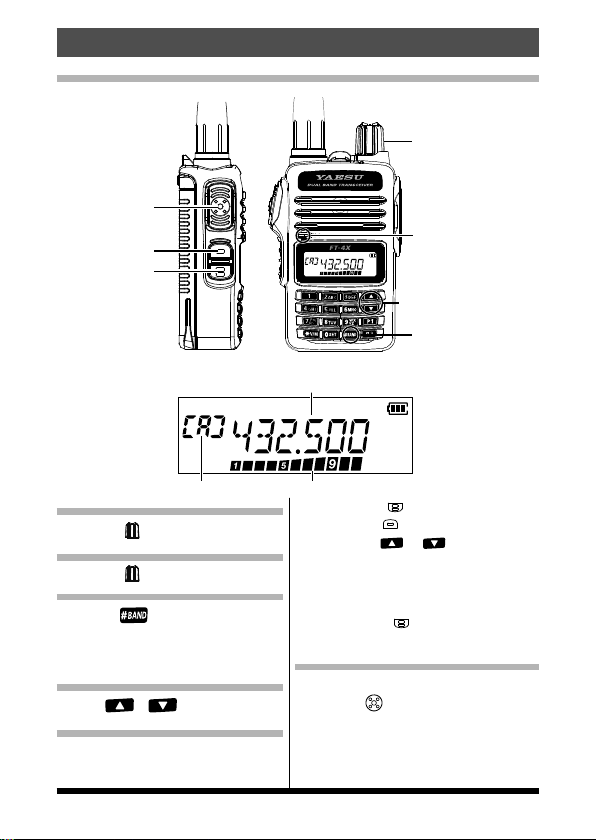
Quick Guide
Operating Frequency
Names and display of Controls
PTT Switch
MONI/T-CALL
Switch
Function Key
Normal operation (VFO Mode
① Turning the Power ON
Rotate the until it clicks.
② Adjusting the volume
Rotate the .
③ Selecting the Operating Band
Press the .
The operating frequency changes between
the 144 MHz Band, the 430 MHz Band,
and the FM Radio Broadcast Band.
④ Tuning the frequency
Press the or .
⑤ Adjusting the squelch setting
The squelch level may be adjusted to mute the
background noise when no signal is received.
1.
2. Press the
3. Press the (Function key) to
⑥ Transmitting Signals
PWR/VOL Knob
Microphone
(Frequency up and down)
[
#
BAND] Key
Key
)
S Meter / PO MeterVFO-A
Press the
press the
squelch level.
* When the squelch level is increased, the noise
is more likely to be silenced, but it may become
more difficult to receive weak signals.
save the setting.
zTransmitting
Press the , then speak into microphone.
(Function key), then
(
MO NI / T- CA LL sw itch
or to adjust the
).
2
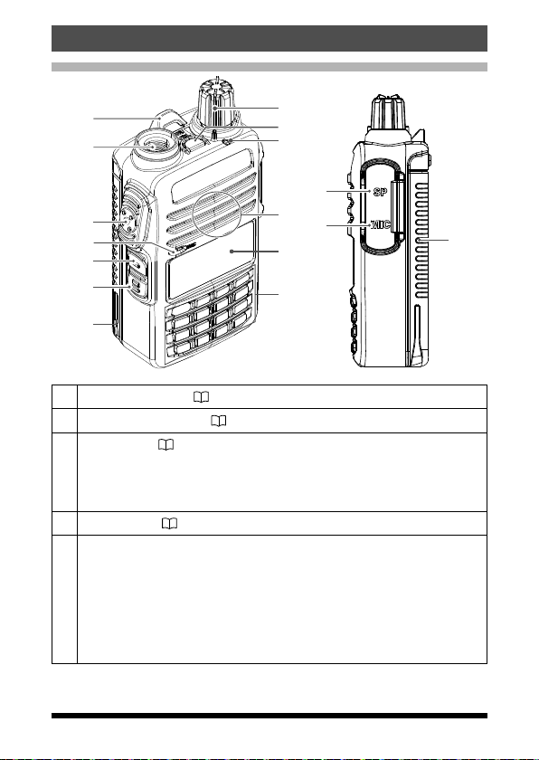
Transceiver
Controls & Connections
①
②
⑧
⑨
⑩
⑭
③
④
⑤
⑥
⑪
⑮
⑫
⑬
⑦
Strap attachment (
①
Antenna Jack (SMA)
②
PTT Switch (
• Press and hold the PTT switch to transmit, and release it to receive.
③
• In the Set mode, press the PTT switch to save the new setting and
return to normal operation.
Microphone (
④
MONI/T.CALL Switch
• USA/Asian version
While pressing and holding the MONI/T.CALL Switch, the squelch is
opened temporarily. Press the Function key, then press the MONI/
⑤
T.CALL Switch to adjust the squelch level.
• European version
Press the MONI/T.CALL switch to activate the T-CALL(1750 Hz).
15)
15)
11)
( 11)
⑦
3

Function Key ( 26)
Pressing the Function key activates the “Secondary” key function.
⑥
Press and hold the Function key enters the Set mode.
In the Set mode, pressing the Function key defines and saves the
setting
Battery pack (
⑦
PWR/VOL Knob
• Turn this control clockwise to turn the transceiver ON and to increase
the volume.
⑧
• Counter-clockwise rotation into the click-stop will turn the transceiver
OFF.
Emergency Key
⑨
Press and hold it for three seconds to enable the Emergency Alarm
beep functions and display the Home channel VHF frequency.
TX/BUSY Indicator Lamp
⑩
This indicator glows green when the squelch opens, and it glows red
during transmit.
Speaker
⑪
LCD (Liquid Crystal Display)
⑫
The display shows the frequency and current operating condition.
Keypad
⑬
The functions of the keypad are described in detail on page 7.
SP jack
⑭
SP jack provides connection for an earphone.
MIC jack
⑮
MIC jack provides connection for a microphone or clone cable.
12)
4
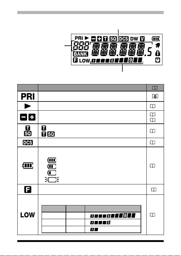
Display
PO Meter: Displays the transmit power level
VFO-A/B
Memory Channel Number
Home Channel Display
Memory Bank
S Meter: Displays the received signal strength
Icon Description
Priority Memory Channel
Memory channel registered as a skip memory
Repeater Shift Direction
Split Memory (two different frequencies)
: Appears when the tone encoder is in use.
: Appears when the tone squelch is in use.
Appears when the DCS is in use.
The battery condition is displayed in 4 steps.
: Full battery charge
: Enough battery charge
: Battery is depleted. Charge battery.
:
(When blinking) Charge battery immediately.
Frequency / Memory Tag / PAGER
Set Mode Item
24
17
22
28
27
13
Appears when the function key is pressed.
TX Power Level Indicator (LOW/MID TX Power Selected)
Tx Po wer Icon TX Pow er Meter duri ng transmis sion
(
No display
LOW
LOW
)
)
HIGH (5 W
)
MID (2.5 W
)
LOW (0.5 W
7
15
5
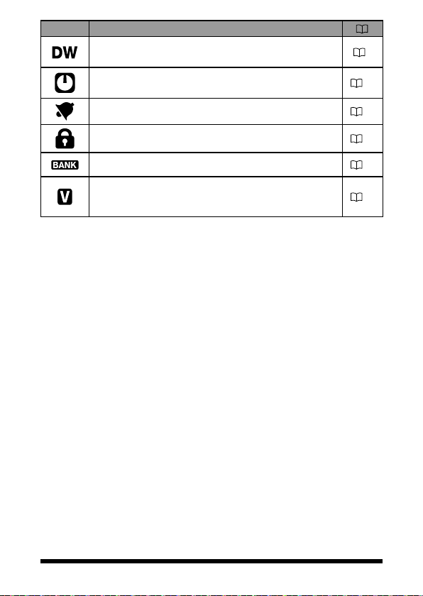
Icon Description
Appears when the Dual Receive (DW) function is
enabled.
Appears when the APO (Automatic Power-Off) function
is enabled.
Appears when the bell function is enabled.
7
26
26
Appears when the lock function is enabled.
Appears when the Memory Bank function is enabled.
Appears when the VOX (Voice Operated Transmit)
function is enabled.
16
22
28
6

The Keypad Functions
Primary Function (Press Key)
Key
Function
#BAND
ABC
DEF
GHI
JKL
MNO
PQRS
TUV
WXYZ
SET
VFO Memory Recall
Activates the
“Secondary” key
function (
pears)
Switches the
band control between VHF, UHF
and FM RADIO
Broadcast*
*: VFO-B only
Switches the
frequency control
V/M
between the VFO
and Memory Systems
Recalls the stored
P1(Programmable
P1
key) setting
Recalls the stored
P2(Programmable
P2
key) setting
1 Number “1”
2
Number “2”
3
Number “3”
4
Number “4”
5
Number “5”
6
Number “6”
7
Number “7”
8
Number “8”
9
Number “9”
0
Number “0”
Activates the
“Secondary” key
ap-
function ( appears)
Memory Offset
Tuning
Recalls the stored
memory channel
Recalls the stored
memory channel
Recalls the stored
memory channel
Recalls the stored
memory channel
Recalls the stored
memory channel
Recalls the stored
memory channel
Recalls the stored
memory channel
Recalls the stored
memory channel
Recalls the stored
memory channel
Recalls the stored
memory channel
–
–
–
Secondary
Inputting
Memory Tag
Moves the cursor
to the right.
–
Numbers “*”, “+”,
“-”, “/”, “@”
Press and hold this
key to complete the
memory channel
registration
Stores to the Home
channel
Stores the Split
Memory
Number “1” –
Number “2”, or
characters “A”, “B”,
“C”, “a”, “b”, or “c”
Number “3”, or
characters “D”, “E”,
“F”, “d”, “e”, or “f”
Number “4”, or
characters “G”, “H”,
“I”, “g”, “h”, or “i”
Number “5”, or
characters “J”, “K”,
“L”, “j”, “k”, or “l”
Number “6”, or
characters “M”, “N”,
“O”, “m”, “n”, or “o”
Number “7”, or
characters “P”, “Q”,
“R”, “S”, “p”, “q”, “r”,
or “s”
Number “8”, or
characters “T”, “U”,
“V”, “t”, “u”, or “v”
Number “9”, or
characters “W”,
“X”, “Y”, “Z”, “w”
,“x”, “y”, or “z”
Number “0” or
space
Function
(Press F +
Deactivates the
“Secondary” key
function (
appears)
PMS(Programmable Memory
channel Scan)
Dual Receive
(DW) function
Recalls the Home
channel
Reverses the
transmit and receive frequencies
while working
through a repeater
DTMF autodialer
setting
Key)
–
–
–
–
–
–
–
–
Third
Function
(Press and
Hold for over
one second)
Enters the Set
mode.
Program Scan
Setting
Memory write
mode
Stores the
P1(Programmable
key) setting
Stores the
P2(Programmable
key) setting
Recalls the
“Weather”
broadcast
channel bank
Activates the
ARTS feature
–
–
–
Key Lock
feature
–
–
–
–
7
Safety Precautions (Be Sure to Read)
Be sure to read these important precautions, and use
Yaesu is not liable for any failures or problems caused by the use or misuse
of this product by the purchaser or any third party. Also, Yaesu is not liable for
damages caused through the use of this product by the purchaser or any third
party, except in cases where ordered to pay damages under the laws.
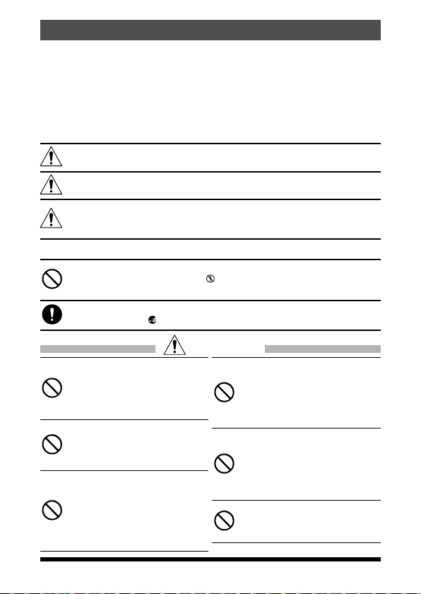
Types and meanings of the marks
DANGER
WARNING
CAUTION
Types and meanings of symbols
These symbols signify prohibited actions, which must not be done to use
this product safely. For example:
disassembled.
These symbols signify required actions, which must be done to use this product
safely. For example,:
this product safely.
This mark indicates an imminently hazardous situation, which, if
not avoided, could result in death or serious injury.
This mark indicates a potentially hazardous situation, which, if
not avoided, could result in death or serious injury.
This mark indicates a potentially hazardous situation, which,
if not avoided, may result in minor or moderate injury or only
property damage.
indicates that the product should not be
indicates that the power plug should be disconnected.
Do not use this product in an
area where RF transmitters are
prohibited, e.g., inside of a hospital,
airplane, or train.
This product can affect electronic or
medical devices.
Do not use this product while riding
a bicycle or driving a car. Accidents
can result.
Be sure to stop the bicycle or car at a
safe place before using this product.
Do not perform transmission in
a crowded place for the safety of
persons using a medical device
such as a cardiac pacemaker.
The radio wave emitted from this
product can cause the medical
device to malfunction and result in an
accident.
8
DANGER
Do not touch any material leaking
from the LCD display with bare
hands.
The chemical may adhere to your skin
or enter your eye, and cause chemical
burns. In such a case, consult the
doctor immediately.
Do not touch any material leaking
from the battery pack with bare
hands.
The chemical that has stuck to your
skin or entered your eye can cause
chemical burns. In such a case,
consult the doctor immediately.
Do not use this product or
the battery charger anywhere
inflammable gas is produced.
A fire or explosion can occur.
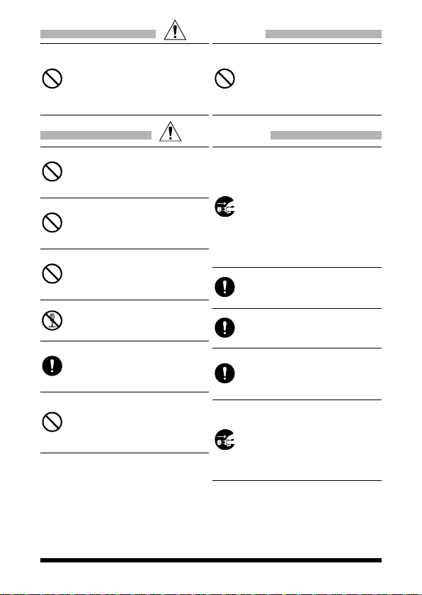
DANGER
Do not solder or short-circuit the
terminals of the battery pack.
A fire, leak, overheating, explosion, or
ignition may result.
Do not carry the battery pack together
with a necklace, hairpin, or small metal
objects. A short circuit can result.
WARNING
Do not power this transceiver with
a voltage other than the specified
power supply voltage.
A fire, electric shock, or damage may
result.
Do not use the battery pack for
any model other than the specified
transceiver.
A fire, leak, overheating, explosion, or
ignition can result.
Do not make very long
transmissions.
The main body of the transceiver may
overheat, resulting component failure
or operator burns.
Do not disassemble or make any
alteration to this product.
An injury, electric shock, or failure may
result.
Keep the terminals of the battery
pack clean.
If terminal contacts are dirty or
corroded, a fire, leak, overheating,
explosion, or ignition can result.
Do not handle the battery pack or
charger with wet hands. Do not
insert or remove the power plug
with wet hands.
An injury, leak, fire, or failure may
result.
If thunder and lightening develop
nearby when an external antenna
is used, immediately turn this
transceiver OFF, and disconnect
the external antenna from it.
A fire, electrical shock, or damage
may result.
If smoke or a strange odor is
emitted from the main body,
battery pack, or battery charger,
immediately turn the transceiver
off; remove the battery pack, and
remove the power plug from
the outlet.
A fire, chemical leak, overheating,
component damage, ignition, or failure
may result. Contact the dealer from
which you purchased this product or
Yaesu Amateur Customer Support.
Do not use the battery pack which
is externally damaged or deformed.
A fire, leak, heating, explosion, or
ignition can result.
Do not use any battery charger
which is not specified by Yaesu.
A fire or failure can result.
When transmitting, keep the
transceiver at least 5.0 mm (3/16
inch) away from your body.
Use only the supplied antenna.Do not
use modified or damaged antennas.
If charging of the battery pack
cannot be completed within
the specified charging time,
immediately remove the power
plug of the battery charger from the
outlet.
A fire, leak, overheating, explosion, or
ignition can result.
9
CAUTION
Do not dangle or throw the
transceiver by holding its antenna.
This may injure others and may also
result in damage and failure of the
transceiver.
Do not use the transceiver in a
crowded place.
The antenna may strike others and
result in a injury.
Do not place this transceiver
indirect sunlight or near a heater.
The case may be deformed or
discolored.
Do not place this transceiver in a
humid or dusty place.
A fire or failure may result.
While transmitting, keep the
antenna as far from you as possible.
Long-time exposure to
electromagnetic waves may have a
negative impact on your health.
Do not wipe the case using thinner
and benzene etc.
Use only a soft, dry cloth to wipe
stains from the case.
If the transceiver will not be used
for an extended period, turn it OFF
and remove the battery pack for
safety.
Do not drop, strike, or throw the
transceiver.
A failure or damage may result.
Keep magnetic cards and video
tape away from the transceiver.
The data recorded on cash cards or
videotapes may be erased.
Charge the battery pack within the
temperature range from +5 °C to
+35 °C (+41 °F to +95 °F).
Charging the battery pack outside this
temperature range can cause leak,
overheating, decrease in performance,
or reduction in service life can result.
When unplugging the power cord
of the battery charger, be sure to
hold the power plug.
Pulling the power cord can damage it
and cause a fire or electronic shock.
Do not use the earpiece microphone
at an extremely high volume level.
Hearing impairment can result.
Keep this product out of the reach
of children.
Injury to the child, or damage to the
transceiver may result.
Install the hand strap and belt clip
securely.
Improper installation may cause the
FT-4XR/XE to fall or drop, resulting in
an injury or damage.
Do not place a heavy object on the
power cord of the AC adapter.
The battery cord can be damaged,
resulting in a fire or electric shock.
Do not use the included AC adapter
to charge any battery pack which
is not specified for use with the AC
adapter.
A fire can result.
Do not operate the transceiver near
the TV or radio.
Radio disturbance can occur in the
transceiver, the TV, or the radio.
Do not use any products other
than the specified options and
accessories.
Failure or miss operation may result.
When the AC adapter is not in use,
remove its power plug from the
outlet.
Before discarding a depleted
battery pack, affix tape or insulating
covering to its terminals.
Be sure to check with the
manufacturer of any hybrid or fuelsaving automobile regarding use of
the transceiver in that car.
Noise generated by an onboard
electrical device (inverter, etc.) can
disrupt the normal operation of the
transceiver.
10
 Loading...