


Yaesu FT 411 Diagram
YAESU MUSEN CO., LTD.
1-20-2 Shimomaruko, Ota-Ku, Tokyo 146-8649, Japan
YAESU U.S.A.
17210 Edwards Rd., Cerritos, CA 90703, U.S.A.
YAESU EUROPE B.V.
P.O. Box 75525 1118 ZN, Schiphol, The Netherlands
YAESU UK LTD.
Unit 12, Sun Valley Business Park, Winnall Close
Winchester, Hampshire, SO23 0LB, U.K.
YAESU GERMANY GmbH
Am Kronberger Hang 2, D-65824 Schwalbach, Germany
YAESU HK LTD.
11th Floor Tsim Sha Tsui Centre, 66 Mody Rd.,
Tsim Sha Tsui East, Kowloon, Hong Kong
144 MHZ FM TRANSCEIVER
FT-411
MKII
OPERATING MANUAL

Contents
Specifications............................................................................................................ 2
Accessories & Options.............................................................................................. 3
Controls & Connectors ............................................................................................ 4
Top Panel ............................................................................................................. 4
Side Panel............................................................................................................. 5
Front Panel ........................................................................................................... 6
Accessories & Options.............................................................................................. 7
Battery Packs and Cases........................................................................................ 7
Battery Removal and Replacement ........................................................................ 8
Battery Chargers ................................................................................................... 8
Speaker/Microphones............................................................................................ 9
Antenna Considerations ...................................................................................... 10
FTS-17A Tone Squelch Unit Installation ............................................................. 10
Operation ............................................................................................................... 11
Preliminary Operating Information ...................................................................... 11
Squelch Setup ..................................................................................................... 11
Important Keypad Information ............................................................................ 12
VFO Frequency & Step Selection ........................................................................ 13
Transmitting ....................................................................................................... 14
Repeater Splits.................................................................................................... 14
Changing the Standard Repeater Shift ............................................................ 15
Memory Storage ................................................................................................. 16
Memory Recall & Copy ...................................................................................... 16
Hiding and Erasing Memories ............................................................................. 17
Call Channel Memory ......................................................................................... 17
Scanning............................................................................................................. 18
Memory Skip Scanning ....................................................................................... 18
Programmable Memory Scanning (PMS)............................................................. 18
Priority Channel Monitoring................................................................................ 19
Multi-Channel Priority Monitoring................................................................. 19
Tone Squelch/Pager Operation ............................................................................ 20
Power Saver........................................................................................................ 21
APO (Automatic Power-Off) ............................................................................... 22
VOX (Voice-Actuated Transmit Switching)......................................................... 22
DTMF Memories ................................................................................................ 22
System Reset ...................................................................................................... 23
In Case of Problems ............................................................................................... 24
Data Cloning .......................................................................................................... 25
Getting the Most from Your Batteries ................................................................... 26

FT-411 MKII OPERATING MANUAL 1
Yaesu FT-411 MK
Ⅱ
Compact 2m Cpu-Controlled
FM Transceiver
The FT-41 1 MK
Ⅱ
is an ultra compact FM hand-held providing up to five watts of RF power
and a wealth of new features for the 2m amateur band. Slightly smaller and lighter than the
FT-23R/73R, the FT-411 MK
Ⅱ
accepts the same battery packs, and has rubber gasket seals
around all external controls and connectors keep out dust and rain or spray, assuring years
of reliable operation even in harsh environments.
Sixteen multi-function keys provide the ultimate in programmability of 49 freely tunable
memories and two vfos. All memories store repeater shifts or separate tx/rx frequencies,
CTCSS (Continuous Tone Controlled Squelch System) tone frequencies and tone encode/
decode selections with one instant-recall call channel memory and two special purpose
memories for limited subband tuning/scanning. Busy channel band or selective memory
scanning is provided along with priority channel monitoring; 1 MHz up/down stepping;
ARS (automatic repeater shift) when tuned to repeater subbands, plus a top panel rotary
dial for memory and frequency selection. The keypad serves as a DTMF encoder during
transmission, and up to 10 DTMF memories can store 15 digits each for quick playback of
commonly used numbers.
The liquid crystal display shows six frequency digits, memory selection, CTCSS tone fre-
quency while setting*, page-received status when paged by a CTCSS tone*, and includes a
bargraph S/PO meter. Yaesu’s power saver system can be set by the operator for optimum
sampling/standby ratio, or can be turned off for packet operation. And our new APO (Au-
tomatic Power Off) system shuts off the transceiver to avoid dead batteries if you doze off
or are called away unexpectedly.
Operation under difficult conditions is simplified by a lamp button illuminating the display
and backlit translucent keypad, diatonically assigned function-dependent keypad beeps.
Please read this manual carefully to gain a clear understanding of the features of the FT-
411 MK
Ⅱ
.
*
: CTCSS and paging features require optional FTS-17A Tone Unit.

FT-411 MKII OPERATING MANUAL2
Specifications
GENERAL
Frequency coverage (MHz): 144 to 147.9995 (version A)
144 to 145.9875 (version B)
Channel steps: 5, 10, 12.5, 20 & 25 kHz
Standard repeater shift: 600 kHz
Emission type: G3E
Supply voltage: 5.5 to 15.0 VDC
Current consumption: Stby (1sec Save) 7mA; Rcv: 150mA;
Transmit (6W): 1300 mA;
Auto Power Off: 6 mA
Antenna (BNC jack): YHA-16 rubber flex antenna
Case size (WHD, in mm): w/FNB/FBA-17: 55×122×32
w/FNB-11H: 55×188×32
w/FNB-12/-14: 55×155×32
Weight (approx.): 550g w/FNB-11H
RECEIVER
Circuit type: Double-conversion superheterodyne
Sensitivity (for 12dB SINAD): better than 0.158 µV (–10 dBµ)
Adjacent channel selectivity: better than 60 dB
Intermodulation: better than 65 dB
Audio output: 0.5 W @8 ohms for 5% THD (12V)
TRANSMITTER
Power output: (see RF Power Chart)
Frequency stability: better than 10 ppm
Modulation system: variable reactance
Maximum deviation: ±5 kHz
FM Noise: better than –40 dB @ 1 kHz
Spurious emissions: better than 60 dB below carrier
Audio distortion (@ 1 kHz): less than 5 %, w/3 kHz deviation
Microphone type: 2-kilohm condenser
Burst tone: 1750 Hz (except version A)
Specifications may be subject to change without notice or obligation.
Battery Type
Dry Cell Case
FBA-17 (6×AA cells)
Ni-Cd Packs
FNB-17 (7.2V, 600 mAh)
FNB-11H (12V, 700 mAh)
FNB-12 (12V, 500 mAh)
FNB-14 (7.2V, 1000 mAh)
RF Output (watts)
2.5
2.5
5.0
5.0
2.5
RF Power Chart

FT-411 MKII OPERATING MANUAL 3
Accessories & Options
FNB-11H 12 V, 700 mAh Ni-Cd Battery Pack
FNB-12 12 V, 500 mAh Ni-Cd Battery Pack
FNB-14 7.2V, 1000 mAh Ni-Cd Battery Pack
FNB-17 7.2V, 600 mAh Compact Ni-Cd Battery Pack
FBA-17 Compact Dry Cell Battery Case for 6 AA-size cells
NC-34B 117 VAC Compact Wall Charger for FNB-14
NC-34C 220-234 VAC Compact Wall Charger for FNB-14
NC-65B 117 VAC Compact Wall Charger for FNB
NC-65C 220-234 VAC Compact Wall Charger for FNB
NC-65F 220 VAC w/Argentine Plug Compact Wall Charger for FNB
NC-65U 220-234 VAC w/UK Plug Compact Wall Charger for FNB
NC-29 Desktop Quick Charger for all above FNB packs
NC-50 Dual-Slot Rapid Charger
CA-7 Charger Sleeve (required w/ NC-50)
PA-6 Mobile DC Adapter/Charger for 7.2 V packs (FNB-14/-17)
MH-32
A2B
External Hand Speaker/Microphone
MH-34
C2B
External Hand Speaker/Microphone
MH-37
B2B
Earpiece/Microphone
YHA-16 Rubber flex antenna
FTS-17A CTCSS Subaudible Tone Squelch Unit
MMB-32A Mobile Hanger Bracket
Availability of accessories may vary: some accessories are supplied as standard per local
regulations and requirements, others may be unavailable in some regions. Check with
your Yaesu dealer for additions to the above list.

FT-411 MKII OPERATING MANUAL4
Controls & Connectors
TOP PANEL
•
EAR Jack
This 2-conductor mini phone jack provides audio
output for an external earphone or optional
Speaker/Mic (listed on previous page). When a
plug is installed in this jack the front panel loud-
speaker is disabled.
‚
MIC Jack
This 2-conductor micro-mini phone jack accepts
microphone input from an external Speaker/Mic
or other external source. When a plug is installed in this jack the front panel micro-
phone is disabled.
ƒ
CALL/DTMF Button
This button toggles between CALL channel and VFO or memory. Also, if the [F/M]
key is pressed just before this button, the DTMF memory mode is toggled on and off
(as indicated by a telephone icon).
„
DIAL Rotary Selector
This 20-position detented rotary switch tunes the operating (or CTCSS tone) frequency
or selects the memory channels, according to which function is selected by the keys on
the front panel. This knob duplicates some of the functions of the up and down arrow
keys for operating convenience.
…
VOL/OFF Control
This control adjusts the volume of the receiver. Turn this control to the fully counter-
clockwise position (into the click stop) to turn the transceiver OFF.
†
SQL Control
This control sets the threshold level at which received signals (or noise) open the noise
squelch. For prolonged battery life and squelch sensitivity when the FTS-17A Tone
Squelch Unit is not in stalled, set this control from counterclockwise just to the point
where noise is silenced (and the BUSY/TX indicator on the front panel is off) when
the channel is clear.
‡
ANTENNA Jack
This BNC jack accepts the supplied YHA-16 rubber flex antenna, or any other an-
tenna designed to provide 50-ohm impedance on the 2m band.
• ‚ ƒ „
‡ † …
FT-411 MKII OPERATING MANUAL 5
Controls & Connectors
SIDE PANELS
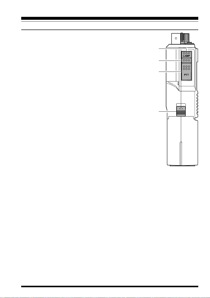
•
LAMP Button
Press this button to illuminate the display and keypad when
necessary.
‚
Monitor (Burst) Button
In the USA version, this button opens the squelch momen-
tarily without disturbing the setting of the SQL control. In
the European version, this button activates the 1750 Hz Burst
tone generator.
ƒ
PTT Button
Press and hold this (Push-to-Talk) button to transmit. The
BUSY/TX indicator glows red while transmitting.
„
Unlock Lever
Slide this mechanical lever upward to release the battery for
removal.
•
‚
ƒ
„
FT-411 MKII OPERATING MANUAL6
Controls & Connectors
FRONT PANELS
•
BUSY/TX Indicator Lamp
This LED indicator glows green when the
noise squelch is open during reception, and
red when transmitting.
‚
Keypad
These sixteen keys select the various operat-
ing features of the transceiver during recep-
tion, and generate DTMF (Dual Tone Multi
Frequency) tone pairs during transmission.
One or two beeps will sound whenever one
of the keys is pressed (if the beeper is ac-
tive). The labels on the faces of the keys indi-
cate their primary functions, while the labels
above fifteen of the keys indicate alternate
functions, which are activated by pressing the
[F/M] key first, and then another key within
three seconds. When referring to alternate key
functions in this manual, we show the alter-
nate key label followed by the primary label
in parentheses (). Primary key functions are
referred to by the labels on the keyfaces.
Remember to press the [F/M] key first (momentarily, unless otherwise indicated) when
you want to use an alternate key function. All key functions are described in the “Opera-
tion” section, and summarized on the •FT-41 1 MK
Ⅱ
Operator’s Quick Reference Card .”
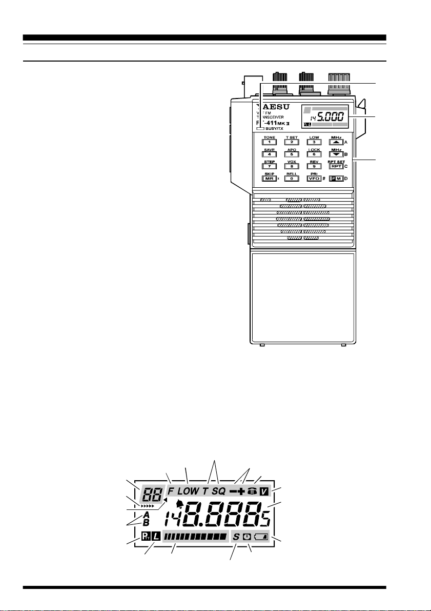
ƒ
LCD (Liquid Crystal Display)
The display shows the selected operating conditions as indicated in the following dia-
gram:
•
‚
ƒ
S/PO Meter
Power Saver Active
Auto Power Off Active
Low Battery Voltage
Operating (or Tone)
Frequency
VOX Enabled
DTMF Memory Mode
Repeater Shift
Tone Encoder/Squelch Enabled
Low Power
Alt Key Active
Memory Number
Memory Tune Active
Memory Skip
VFO Selection
PTT Switch Locked
Keypad Locked

FT-411 MKII OPERATING MANUAL 7
Accessories & Options
BATTERY PACKS AND CASES
The following rechargeable Ni-Cd battery packs are recommended for use with the FT-
411 MK
Ⅱ
:
FNB-11H 12V 700 mAh
FNB-12 12V 500 mAh
FNB-14 7.2V 1000 mAh
FNB-17 7.2V 600 mAh
The following battery cases are also available for operating the FT-411 MK
Ⅱ
with non-
rechargeable dry cell batteries (not supplied):
FBA-17 Battery Cases for 6 ‘AA’ (UM-3) batteries
In some countries, one or more of the above may be supplied with the transceiver. If not,
contact the nearest Yaesu dealer to purchase the desired battery pack or case. We do not
recommend the use of any other type of battery with the FT-411 MK
Ⅱ
, and using another
type may affect your warranty.
The Ni-Cd packs listed above may be recharged either while attached to the transceiver or
separately, using the battery chargers described on the following pages. Each Ni-Cd pack
should be fully charged before it is used with the transceiver for the first time. Note that
most of these packs require different wall chargers: NC-34B/C for FNB-14, NC-65B/C/
F/U for FNB-11H, FNB-12 or FNB-17. Make certain that you use the correct charger for
each pack. The NC-29 Desktop Quick charger may be used with all of these Ni-Cd packs.
RF power output from the transmitter will differ in some cases according to which type of
battery is used, as shown in the RF Power Chart in the Specification.

FT-411 MKII OPERATING MANUAL8
Accessories & Options
BATTERY REMOVAL AND REPLACEMENT
•
Make sure that the VOL control is set into the OFF click-stop, and remove the protec-
tive soft or hard case, if used.
‚
Grasp the upper portion of the transceiver with
your left hand, so that your palm is over the
speaker and your left thumb is on the UNLOCK
button.
ƒ
Move the UNLOCK button in the direction in-
dicated by the small arrowhead, while using your
right hand to slide the battery case toward the side with the UNLOCK button. The
battery case should slide smoothly out of its track.
„
To open the FBA-17 battery cases, place both of your thumbs on the mounting tracks on
top of the case and gently pry the tracks apart. Install six batteries, paying attention to the
polarity indicated inside the case. Always replace all six cells.
Do not attempt to open any of the rechargeable Ni-Cd packs.
…
To replace the battery case or Ni-Cd pack, repeat steps
‚
and
ƒ
above, simply
sliding the battery case in the other direction after aligning the shorter side of the
battery case with the track below the UNLOCK button.
BATTERY CHARGERS
It is not necessary to remove the battery pack from the transceiver when charging, but
transceiver operation may be impaired (by noise) while charging the battery. Therefore we
recommend having an extra battery pack on hand so that the transceiver can be used while
the spare pack is being charged.
Do not attempt to recharge dry cell batteries used in the FBA-17.
NC-34B/C
The NC-34B (117 VAC) and NC-34C (220-234 VAC) are compact chargers for recharg-
ing the FNB-14 Ni-Cd battery pack from the AC line. A completely discharged pack re-
quires approximately 15 hours to recharge with the NC-34B/C. Do not attempt to charge
the FNB-11H, FNB-12 or FNB-17 with the NC-34B/C, as the charging voltage and
current are not correct for those packs.
NC-65B/C/F/U
The NC-65B (117 VAC), NC-65C (220-234 VAC), NC-65F (220 VAC w/Argentine plug),
and NC-65U (220-234 VAC w/UK plug), are compact chargers for recharging the FNB-
11H, FNB-12 or FNB-17 Ni-Cd battery packs from the AC line. A completely discharged
pack requires approximately 15 hours to recharge with the NC-65B/C/F/U. Do not at-
tempt to charge the FNB-14 with the NC-65B/C/F/U, as the charging voltage and current
are not correct for this pack.
 Loading...