

Yaesu FT-410 Operation Manual

HF/50 MH
z
T
ransceiver
FT-410
O
peraTiOn
M
anual
YAESU MUSEN CO., LTD.
Tennozu Parkside Building
2-5-8 Higashi-Shinagawa, Shinagawa-ku, Tokyo 140-0002 Japan
YAESU USA
6125 Phyllis Drive, Cypress, CA 90630, U.S.A.
YAESU UK
Unit 12, Sun Valley Business Park, Winnall Close
Winchester, Hampshire, SO23 0LB, U.K.
Download - http://www.radioaficion.com/hamfiles/

Page 2 FT-410 O
peraTiOn Manual
T
able OF
c
OnTenTs
Front Panel Buttons and Knobs ........................ 3
Display Indications ............................................. 6
Rear Panel Jacks ................................................ 7
Supplied MH-31B8 Microphone ......................... 8
Accessories & Options ...................................... 9
Supplied Accessories ......................................................... 9
Available Options ............................................................... 9
Installation ......................................................... 10
Connection of Antenna and Power Supply....................... 10
About Coaxial Cable .........................................................11
Grounding ........................................................................ 12
Installation ......................................................... 12
VL-1000 Linear Amplier Interconnection ........................ 13
Interfacing to Other Linear Amplier ................................. 14
Easy Operation ................................................. 15
Receiving ................................................................... 15
Transmit ..................................................................... 15
Menu Operation ............................................................... 15
Resetting the Microprocessor .......................................... 16
Menu Mode Reset ..................................................... 16
All Reset .................................................................... 16
Receiving........................................................... 17
Tuning Steps .................................................................... 17
Change the Tuning Step of the [MAIN DIAL] Knob .... 17
About the [UP]/[DWN] buttons of the MH-31B8
...
............ 17
Clarier
....
......................................................................... 18
DIAL Lock
....
..................................................................... 18
ATT (Adjust the Receiving Sensitivity
)
...
.......................... 18
Noise Blanker (Interference Rejection
)
...
......................... 18
Convenience Features ..................................... 19
AGC (Tool for Comfortable and effective Reception
)
...
... 19
SHIFT (Interference Rejection
)
...
..................................... 19
RF GAIN ........................................................................... 20
SSB/AM Mode Transmission ........................... 21
TX Power Adjustment ....................................................... 21
CW Mode Operation ......................................... 22
Setup for Straight Key
(and Straight Key emulation) Operation ....... 22
Using the Built-in Electronic Keyer ................................... 23
Adjusting the Keyer Speed ........................................ 23
Memory Operation ............................................ 24
Convenient Memory functions .......................................... 24
Quick Point: ............................................................... 24
Regular Memory Operation .............................................. 24
Memory Storage ........................................................ 24
Memory Channel Recall ............................................ 24
Regular Memory Operation .............................................. 25
Erasing Memory Channel Data .................................. 25
Memory Tune Operation ............................................ 25
Scanning Operation ......................................... 26
VFO and Memory Scanning ............................................. 26
Preparation ................................................................ 26
VFO/Memory Scan .................................................... 26
Operation on Alaska Emergency Frequency:
5167.5 kHz (U.S. Version Only) ........................ 27
Preparation ............................................................................. 27
Operation ................................................................... 27
Specications ................................................... 28
FCC Notice ........................................................ 30
Download - http://www.radioaficion.com/hamfiles/
Page 3FT-410 O
peraTiOn Manual
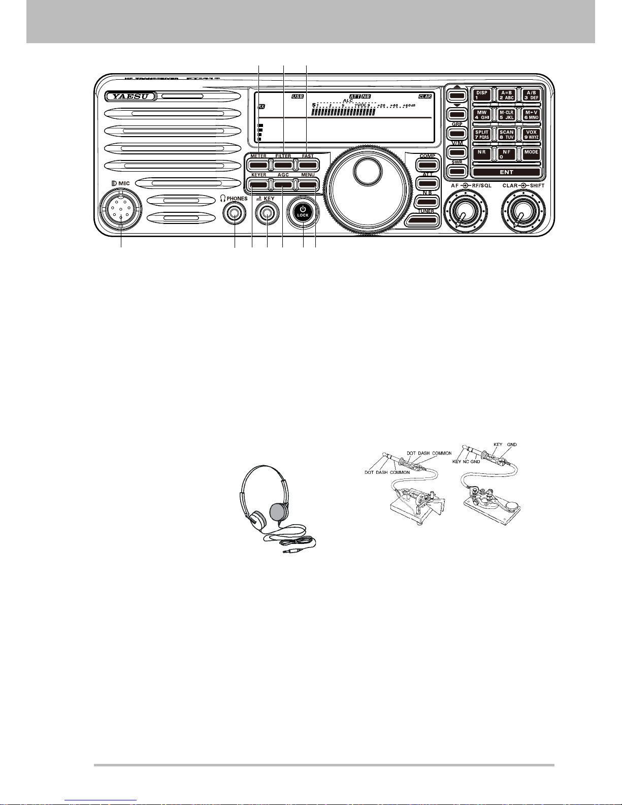
FrOnT panel buTTOns and KnObs
14.195.000
M-012
1 2 3
4 6 7 8 9 105
1. METER Button
Press this button to change the meter function in
the transmit mode as follows.
PO ALC SWR PO
PO: Indicates the average power output level.
ALC: Indicates the relative ALC voltage.
SWR
:
Indicates
the Standing Wave Ratio
(Forward/Reected).
2.
Filter Button
Press this button to change the lter.
3. FAST Button
Pressing this button will increase or decrease the
tuning rate of the [MAIN DIAL] knob.
4.
MIC Jack
This
8-pin jack accepts input from a supplied
Hand Microphone.
5.
PHONE Jack
A 3.5 mm, 3-contact jack
accepts either monaural or
stereo headphones with 2
or 3-contact plugs. When
a plug is inserted, the
loudspeaker is disabled.
N
ote
:
When wearing headphones,
we recommend that you turn the AF GAIN levels
down to their lowest settings before turning
power on, to minimize the impact on your hearing
caused by audio “pops” during switch-on.
6.
KEYER Button
This button toggles the internal CW keyer on and
off.
7. KEY Jack
This 3.5 mm, 3-contact jack accepts a CW key or
keyer paddles (for the built-in electronic keyer),
or output from an external electronic keyer.
Pinout is shown below. Key up is 5 volts, and key
down current is 0.5 mA.
Do not use the plug except the 3.5-mm 3-pin
type plug. If the plug in correct size is not used
the radio may be harmed or damaged.
If the Keyer plug is removed from the jack while
the FT-410 is in operation, the FT-410 may be
switched to the transmit mode.
Turn off the power of the FT-410 before
connecting or disconnecting the Keyer.
8. AGC Button
This button selects the AGC characteristics for
the receiver.
9. Power / LOCK Button
Press and hold in this button for one second to
turn the transceiver on or off. Press this button
the locking of the [MAIN DIAL] knob and some
switches, to prevent accidental frequency
changes.
10. MENU Button
Press this button, the Menu Item and a title for
the Menu Mode will appear in the display.
Page 4 FT-410 O
peraTiOn Manual
14.195.000
M-012
16
11 12 13 1514
17 18 19 20 22
21 23
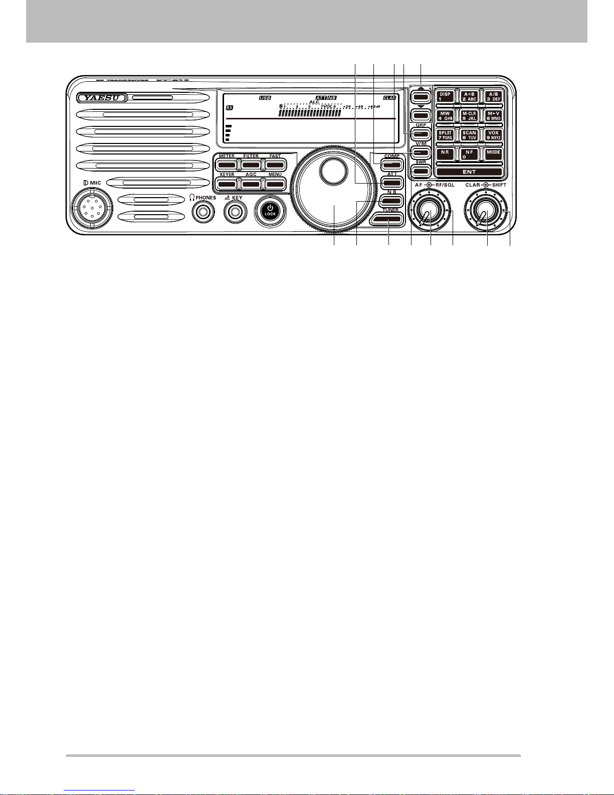
11. ATT Button
This button selects the ATT level.
12. COMP Button
This button turns the Speech Processor on and
of
f.
13. V/M Button
This
button toggles frequency control between
VFO-A and the memory system. In memory
mode.
14.
GRP Button
Pressing
this button allows you to select a
memory group.
15. / Button
These buttons select the operating band.
16.
MAIN DIAL Knob
This knob adjusts the operating frequency
.
17. NB Button
This button turns the IF Noise Blanker on and off.
Press this button to reduce short-duration pulse
noise.
18. TUNER Button
Press this
button momentarily to toggle the
Automatic Antenna Tuner on/off.
Press and hold in this button to begin the
automatic Tuning.
19. SWR Button
Indicates the Standing Wave Ratio (Forward/
Reected).
20. AF Knob
This knob sets the receiver’s audio volume level.
Typically, you will operate with this control set
between the 9 o’clock and 10 o’clock positions.
21. RF/SQL Knob
In
the factory default, this knob adjusts the gain
of the receiver’s RF and IF stages. Using Menu
Item “SQL/RF Gain”, this knob may be changed
to function as a Squelch control, which may be
used to silence background noise when no signal
is present.
22. CLAR Knob
Pressing this
button activates the Clarifier, to
allow temporarily offsetting the receive frequency.
23. SHIFT Knob
This knob
shifts the IF DSP passband to reduce
an interfering signal which is inside the IF
passband.
FrOnT panel buTTOns and KnObs
Page 5FT-410 O
peraTiOn Manual
14.195.000
M-012
26
35 36
27 282425
29
30
32
33
34
31
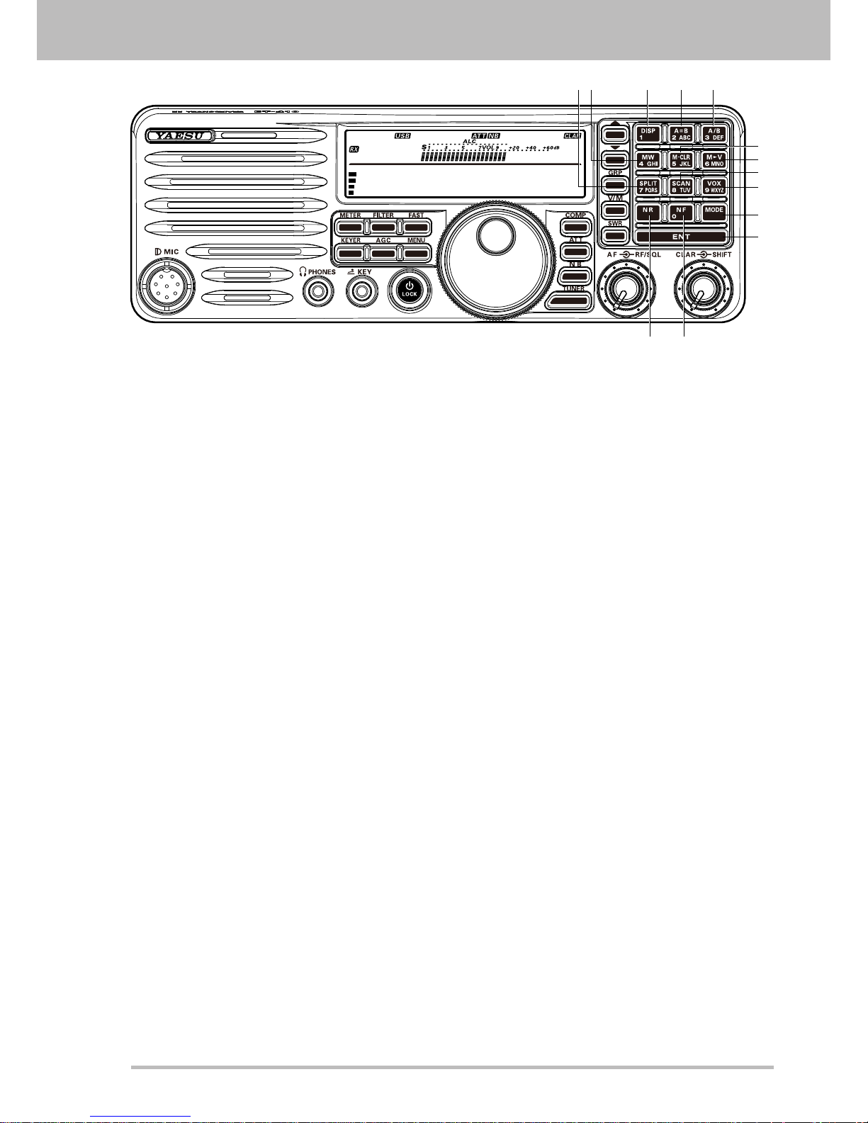
24. SPLIT Button
Press this button to activate split frequency
operation between VFO-A, used for reception
and VFO-B, used for transmission (or vice
versa).
25. MW Button
Pressing this button copies the current operating
data into the currently selected memory channel,
over-writing any previous data stored there.
26. DISP Button
27.
A=B Button
Pr
ess this button momentarily to transfer data
from VFO-A frequency to VFO-B, overwriting the
previous contents in VFO-B. Use this key to set
both VFO-A and VFO-B to the same frequency
and mode.
28. A/B Button
T
his button toggles the frequency control
between VFO-A and VFO-B.
29.
M-CLR Button
Press this button, a memory channel is cleared.
30. M
V Button
Press this button, a frequency and a mode of a
memory channel are forwarded to VFO.
31. SCAN Button
Press this button to initiate the upward
scanning
of VFO frequencies or memory channels.
32. VOX Button
Press this button to activate the VOX (voiceactuated transmitter switching) feature in the
SSB, and AM modes.
33.
MODE Button
These buttons select the operating mode.
34. ENT Button
Press this button, setting is Oprating frequency.
35.
NR Button
Press
this button to activate Noise Reduction
operation
36. NF Button
Press this button to activate Notch Filter
operation.
FrOnT panel buTTOns and KnObs
Page 6 FT-410 O
peraTiOn Manual
d
isplay indicaTiOns
14.195.000
M-012
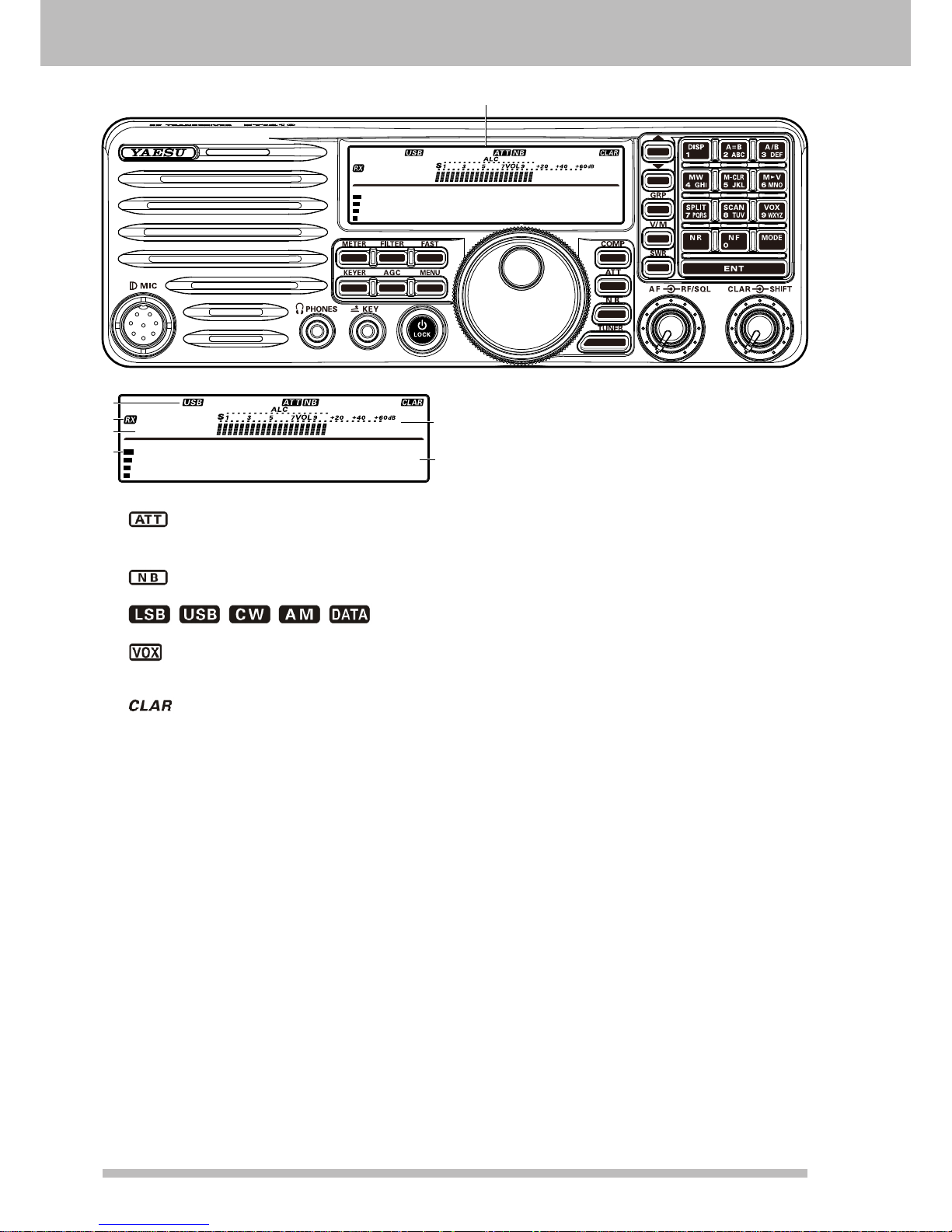
Display
14.195.000
M-012
2
3
4
5
6
1
1. Information Display
: Indicates the RF attenuator status (“ON”
or “OFF”) selected for operation by the
[
ATT] button.
: Indicates the Noise Blanker status (“ON”
or “OFF”).
/ / / / : Displays
the currently selected operating mode.
: This indicator appears whenever the VOX
(automatic voice-actuated transmitter
switching) circuit is activated.
: This indicator appears whenever the
Clarier function is activated.
2. TX / RX Display
TX: This indicator appears during transmission.
RX: This indicator appears whenever the
receiver squelch is open.
3. Indicates the operating band name, and
memory channel
When in VFO mode, the operating band name
(A or B) is displayed.While in memory mode, and
the memory channel number are displayed.
4. AF level indication
5.
Meter
While receiving,
the received signal strength is
displayed.
While transmitting, the meter displays PO,
ALC, or SWR (determined by the [METER/DIM]
button).
6. Frequency Display
The operating frequency is displayed.

Page 7FT-410 O
peraTiOn Manual
r
ear
p
anel
J
acKs
1 2
87654
3
1. DC IN Jack
This is the DC power supply connection for
the transceiver. Use the supplied DC cable
to connect directly to the car battery or to a
DC power supply, which must be capable of
supplying at least 22 A @13.8 VDC.
(viewed from rear panel)
+
-
2. ANT Jack
Connect your antenna here, using a type-M (PL-
259) coaxial connector and 50 Ohm coaxial
feedline.
Warning!: High Power RF voltage is present
at the TX RF section of the transceiver while
transmitting. Absolutely! Do not touch the TX RF
section while transmitting.
3. GND Terminal
For safety and optimum performance, use this
terminal to connect the transceiver to a good
earth ground. Use a large diameter, short braided
cable for making ground connections. Refer to
page 12 for other notes about proper grounding.
4.
TUNER Jack
This 8-pin jack is used for Connection to the FC40 External Automatic Antenna
Tuner.
TXD
TX GND OUT
+13.8V OUT
GND
TUNER SENSE
TX INH IN
RXD
RESET OUT
(viewed from rear panel)
5. LINEAR Jack
This 10-pin output jack provides band selection
data, which may be used for control of the
optional VL-1000 Solid-State Linear Amplier.
BAND DATA-A (LSB)
TX GND OUT
+13.8V OUT
TXREQ IN
GND
BAND DATA-B
BAND DATA-C
BAND DATA-D (MSB)
TX INH IN
EXT ALC IN
(viewed from rear panel)
6. DATA Jack
This 6-pin input/output jack provides receiver
audio and squelch signals, and accepts transmit
(AFSK) audio and PTT control, from an external
packet TNC.
SQL OUT
FSK IN
GND
DATA IN
DATA PTT
DATA OUT
(viewed from rear panel)
7. CAT Jack
This 9-pin serial DB-9 jack allows external
computer control of the FT-410. Connect a
(straight) serial cable here and to the RS232C COM port on your personal computer (no
external interface is required).
CTSRTS
GND
SERIAL IN
SERIAL OUT
Connect to
,
Connect to
,
N/A
Connect to
,
(viewed from rear panel)
8. EXT SPKR Jack
This 3.5-mm, 2-pin jack provides variable audio
output for an external speaker. The audio output
impedance at this jack is 4 - 16 Ohms and the
level varies according to the setting of the front
panel’s [AF] knob. Inserting a plug into this jack
disables the internal loudspeaker.
Page 8 FT-410 O
peraTiOn Manual
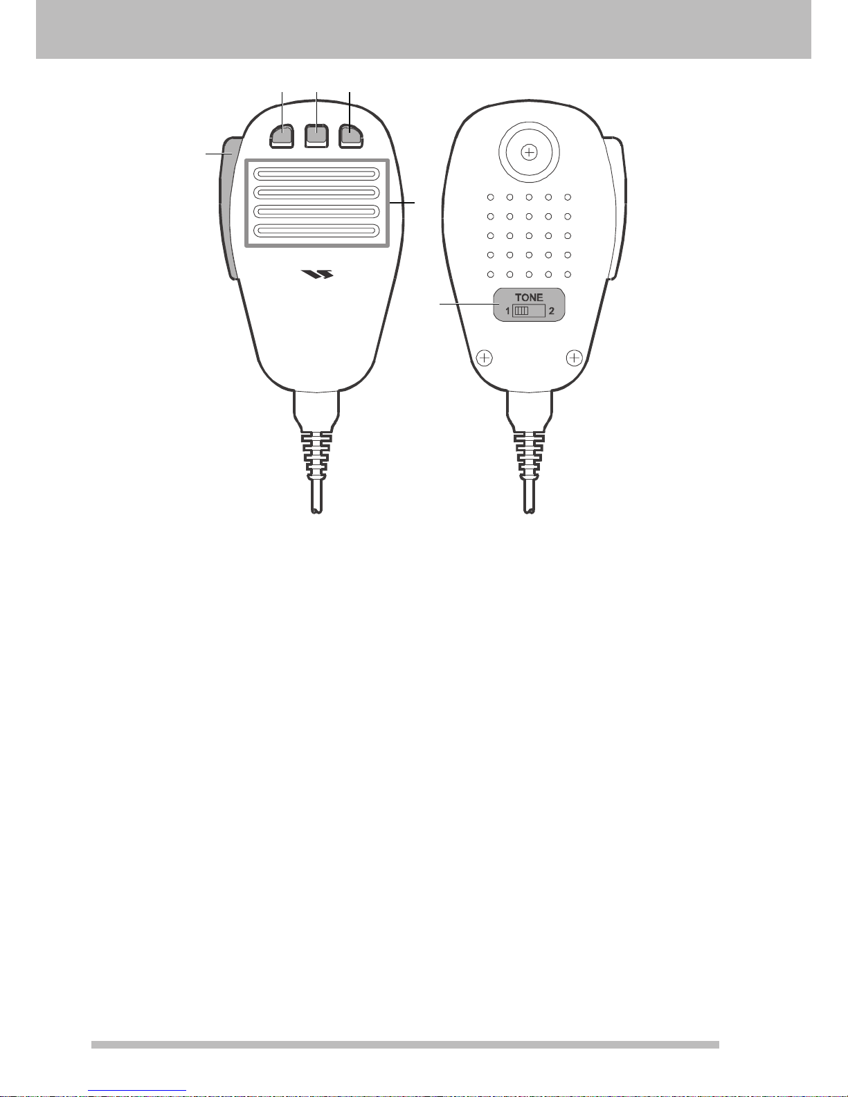
s
upplied
MH-31
b8
M
icrOpHOne
DYNAMIC MICROPHONE
MH-31
DWN FST UP
2 3 4
5
1
6
1. PTT Switch
Press this Switch to transmit, and release it to
receive after your transmission is completed.
2.
DWN Key
Press to tune down, hold to start scanning.
3. FST (FAST) Key
The
FST Button on the transceiver should be set
for momentary operation.
4.
UP Key
Press to tune up, hold to start scanning.
5. MIC
The microphone is located here. Speak into the
microphone in a normal voice level.
T
he microphone should be positioned within
2 inches (5 cm) from the mouth for optimum
performance.
6. TONE Switch
Position
1 provides flat-audio-characteristic
transmit audio.
Position 2 attenuates low audio tones, for
improved clarity in moderate band conditions, or
if you have a naturally deep voice.

Page 9FT-410 O
peraTiOn Manual
a
ccessOries
& O
pTiOns
S
upplied AcceSSorieS
Hand Microphone (MH-31B8) 1 pc P/N: M3090086A
DC Power Cord with Fuse 1 pc P/N: T9025225
Fuse 1 pc P/N: Q0000074
Operation Manual 1 pc
Warranty Card 1 pc
A
vAilAble optioNS
External Automatic Antenna Tuner (for Wire Antenna) FC-40
Active-Tuning Antenna System ATAS-25
Active-Tuning Antenna System ATAS-120A
Solid-State Linear Amplier/AC Power Supply VL-1000 / VP-1000
Band Data Cable (for VL-1000) CT-118
Desktop Microphone MD-100
Hand Microphone MH-31
B8
Lightweight Stereo Headphone YH-77STA
Mobile Mounting Bracket MMB-90
Carrying Handle MHG-1
Linear Amplier Connection Cable SCU-28
Page 10 FT-410 O
peraTiOn Manual
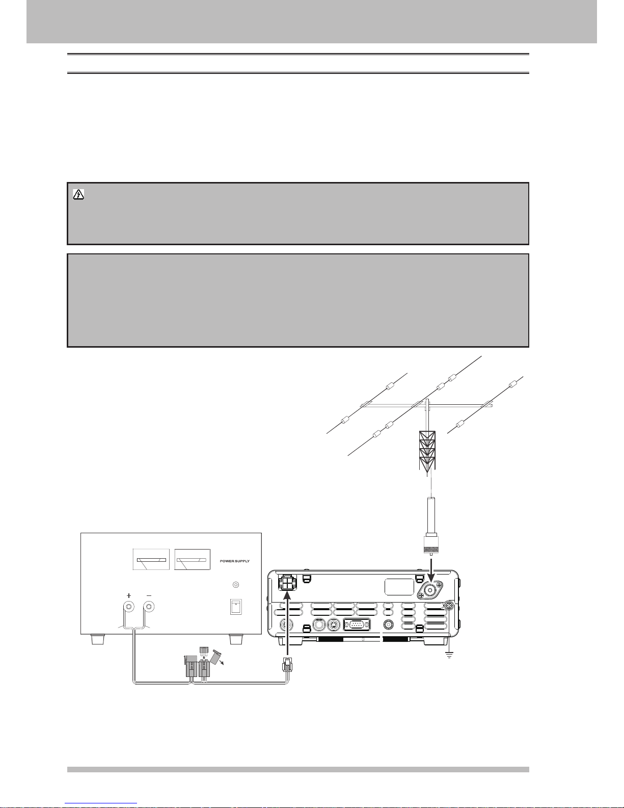
insTallaTiOn
c
oNNectioN of ANteNNA ANd power Supply
The FT-410 is designed for use with any antenna system providing a 50 Ohm resistive impedance at the
desired operating frequency. Every effort should be made to ensure the impedance of the antenna system is
as close as possible to the specied 50-Ohm value. Note that the “G5RV” type antenna does not provide 50Ohm impedance on all HF Amateur bands, and an external wide-range antenna coupler must be used with
this antenna type.
Any antenna to be used with the FT-410 must, ultimately, be fed with 50 Ohm coaxial cable. Therefore, when
using a “balanced” antenna such as a dipole, remember that a balun or other matching/balancing device
must be used to ensure proper antenna performance.
Warning!
The 100V RF voltage (@100 W/50 Ω) is applied to the TX RF section of the transciver while
transmitting.
Do not touch the TX RF section absolutely while transmitting.
CAUTION
Permanent damage can result if improper supply voltage, or reverse-polarity voltage, is applied
to the FT-410. The Limited Warranty on this transceiver does not cover damage caused by
application of AC voltage, reversed polarity DC, or DC voltage outside the specied range of
13.8V ±15%.
When replacing fuses, be certain to use a fuse of the proper rating. The FT-410 requires a 25A
fast-blow fuse.
AC Power Supply
FT-410
A
0 5 20 30 40
POWER
ON
OFF
RED BLACK
FUSE: 25A
V
0 5 10 15 20
ANNTENA
 Loading...