

Page 1
C4FM/FM 144/430MHz
DUAL BAND DIGITAL TRANSCEIVER
FT3DR
FT3DE
Instruction Manual (APRS Edition)
Page 2

Table of Contents
APRS® initial settings ........................................................................................................ 2
Initial setting process for APRS operations ................................................................... 2
When operating APRS using the GPS function ............................................................ 3
When operating APRS without using the GPS function ................................................ 3
Setting your own station call sign.................................................................................. 5
Setting the APRS baud rate .......................................................................................... 6
Setting the symbol of your own station ......................................................................... 7
Receiving APRS
Setting the APRS operating frequency .........................................................................9
Receiving beacons........................................................................................................ 9
Description of the APRS STATION LIST screen and operations ................................ 10
Notification of beacon or message arrival in a pop-up screen
APRS POPUP function ............................................................................................... 21
Screen when BND 2 s - BND 60 s is selected ........................................................ 22
Audio notification of a beacon or message received APRS RINGER function ........... 23
Displaying RAW packet data ......................................................................................23
Deleting a beacon station from the list ........................................................................ 24
Transmitting APRS
Transmitting a beacon manually ................................................................................. 25
Switching between automatic and manual beacon transmission................................ 25
Setting the automatic beacon transmit interval ........................................................... 26
Setting the SmartBeaconing™.................................................................................... 26
Registering status text ................................................................................................ 28
Selecting a position comment ..................................................................................... 29
Setting the digipeater route ......................................................................................... 29
®
APRS
message screen and operating instructions ....................................................... 31
Description of the APRS MESSAGE LIST screen and operations .............................31
Description of the APRS MESSAGE LIST detail screen and operations .................... 32
Message edit screen and description of operations.................................................... 33
Receiving messages ................................................................................................... 34
Filter setting for messages received ........................................................................... 35
Deleting a message from the list................................................................................. 36
Transmitting APRS
Creating and sending messages ................................................................................ 37
APRS Set Mode List ....................................................................................................... 42
APRS Set mode function list .......................................................................................... 45
®
beacons ............................................................................................... 9
®
beacons ......................................................................................... 25
®
messages ....................................................................................... 37
1
Page 3
APRS® initial settings
APRS (Automatic Packet Reporting System) is a communication system to exchange
GPS location data and packet messages; it was developed and is supported by Bob
Bruninga (WB4APR). Position data may be entered manually in advance or automatically
from the built-in GPS satellite receiver.
When an APRS signal is received from a partner station, the direction, distance, speed
etc. of the partner station as seen from your own station will be shown on the display of
your transceiver.
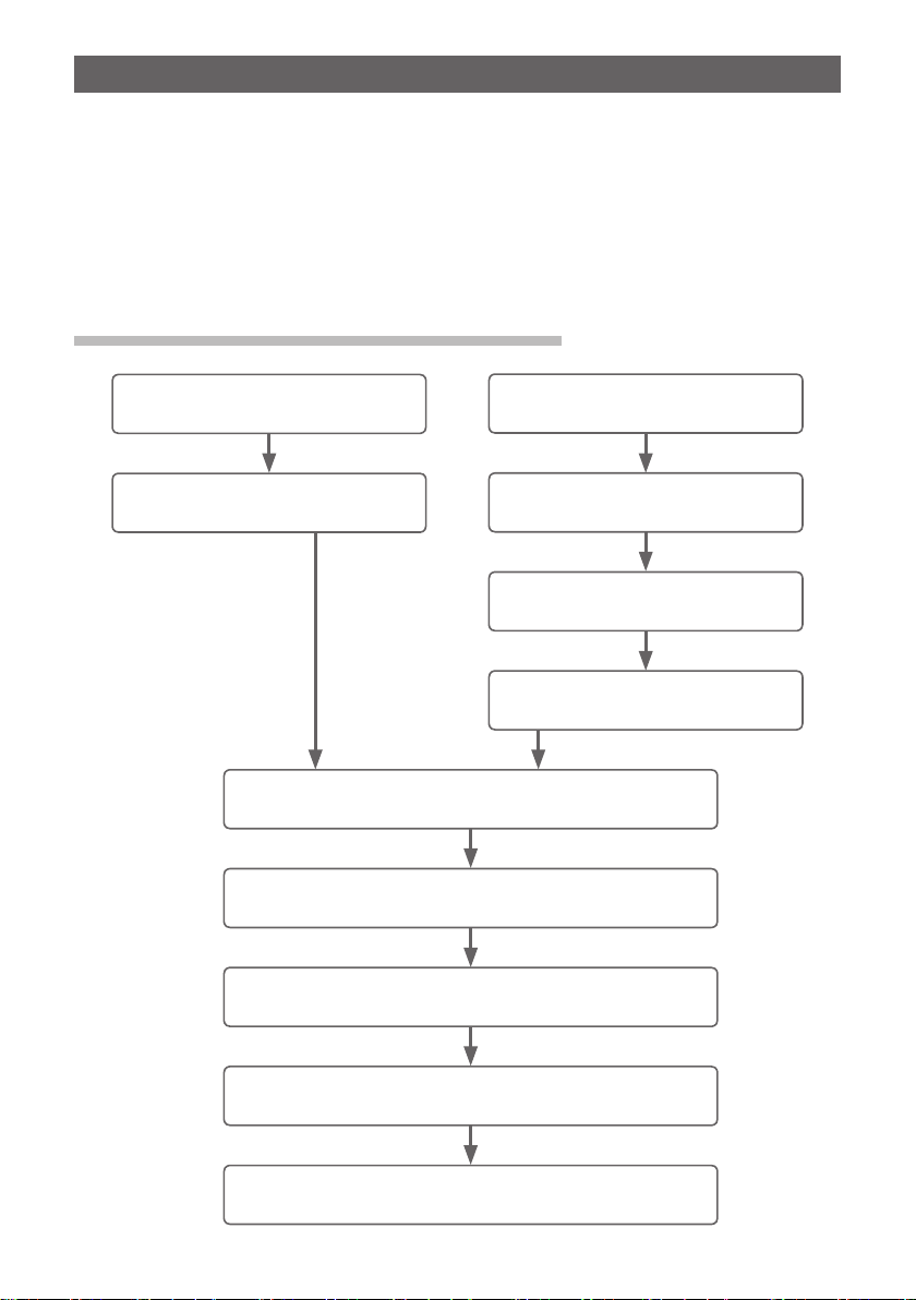
Initial setting process for APRS operations
Enabling the GPS function
(page 3)
Turning the GPS function ON
(page 3)
Setting your own station call sign
Setting the APRS baud rate and turning ON the APRS
Setting the symbol of your own station
Turning the GPS function OFF
Setting the clock of this device
Setting the position of your own
(page 5)
function (page 6)
(page 7)
Disabling the GPS function
(page 3)
(page 3)
(FT3DR/DE Operating Manual)
station (page 4)
Setting the frequency in Band B
(page 9)
Setting the APRS beacon transmission according to your
operation preferences (page 25)
2
Page 4

When operating APRS using the GPS function
When the GPS function is activated, the internal clock setting and location coordinates
of your own station will be acquired from the GPS satellite signals automatically. We
recommend that the GPS function be used in mobile operations.
1 Press and hold the [DISP] key → Touch [APRS] → [20 GPS POWER].
2 Turn the DIAL to select “GPS ON”.
GPS ON: GPS function is usable.
GPS OFF: GPS function is not usable.
Reference Factory shipping value: GPS ON
3 Press the PTT.
To exit the set mode and return to the operating screen.
In order to use the GPS satellite data for your own position information, press and hold
the [DISP] key → Touch [APRS] → [24 MY POSITION] to “GPS”. If [24 MY POSITION],
is set to “Manual”, the coordinates registered in set menu “P1-P10” will be used by your
transceiver for APRS operations, and the acquired GPS data will become invalid.
Tips
• The position GPS coordinates for your own station can be registered in 10 memories (P1 - P10). The
registered coordinates can be set as the position information of your own station (page 58).
• When using the GPS function in APRS operations, be sure to set [APRS] → [24 MY POSITION] to
“GPS”.
• When using the GPS function, the current consumed will increase by about 18 mA. As a result, the
battery standby time is shorter compared to when the GPS function is set to OFF.
When operating APRS without using the GPS function
When operating APRS without using the GPS function, follow the procedure below to
manually set the clock and position information.
y Setting the clock
If the internal clock of this device is set, the time will be reflected in the time display of
the APRS screen. Please refer to “Setting Clock Time” (FT3DR/DE Operating Manual) on
how to set the time.
1 Press and hold the [DISP] key → Touch [APRS] → [21 GPS TIME SET].
2 Turn the DIAL to select “MANUAL”.
3 Press the PTT.
The GPS clock will be set to MANUAL and the set mode
will be cancelled.
3
Page 5
y Setting the position information
Enter the position information of your own station manually.
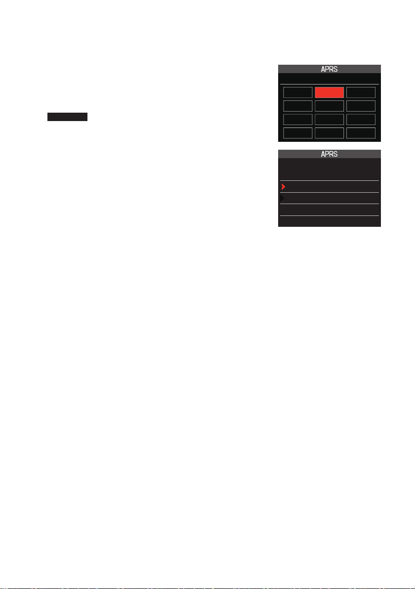
1 Press and hold the [DISP] key → Touch [APRS] → [24 MY POSITION].
2 Turn the DIAL to select [Manual] and press the [DISP]
key.
A screen to enter the position information of your own
station will be displayed.
Reference Factory shipping value: GPS
3 Press the [DISP] key.
The cursor will move to the item for setting the latitude.
4 Turn the DIAL to select “N (North Latitude)” or “S (South
Latitude)” press the [DISP] key.
The cursor will move to the item for setting the “degree”.
5 Turn the DIAL to select [Degree] and press the [DISP]
key.
The cursor will move to the item for setting the “Minute”.
24 MY POSITION
GPS Manual P1
P2 P3 P4
P5 P6 P7
P8 P9 P10
24 MY POSITION
Manual :
LAT N 0°00.00’
(’00”)
LON E 0°00.00’
(’00”)
6 Turn the DIAL to select [Minute] and press the [DISP]
key.
The cursor will move to the item for setting the “1/100th Minute”.
7 Turn the DIAL to select [1/100th Minute] and press the [DISP] key.
The seconds will be displayed within parentheses.
8 Turn the DIAL to select “LON” and press the [DISP] key.
The cursor will move to the item for setting the longitude.
9 Turn the DIAL to select “E (East Longitude)” or “W (West Longitude)” and press the
[DISP] key.
The cursor will move to the item for setting the “Degree”.
10 Enter the “degree”, “minute” and “1/100th minute” in the same way as Step 5-7.
11 Press the [DISP] key.
The position information will be set.
12 Press the PTT.
To exit the set mode and return to the operating screen.
4
Page 6
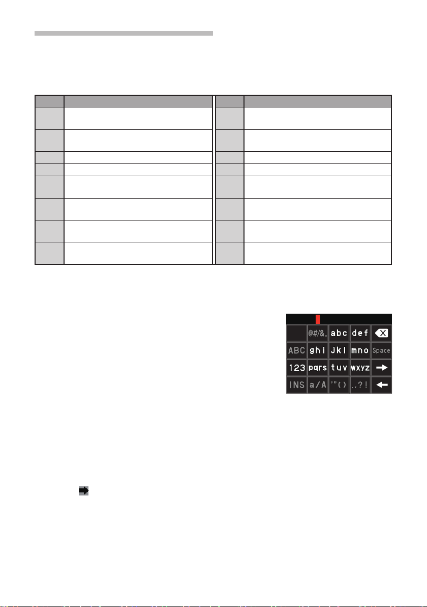
Setting your own station call sign
Register your own station call sign in order to send and receive messages and to transmit
beacons in APRS. Enter the call sign like “JA1ZRL-7”. The “-7” in the call sign indicates
the SSID (Secondary Station Identifier) of which there are 16 types, including one with no
SSID. Generally, the SSIDs shown in the table below are used in APRS.
SSID Description SSID Description
NIL Fixed stations that can exchange mes-
sages
-1 1200 bps narrow-to-middle band digipeater
-2 9600 bps digipeater -10 I-Gate station, Internet connection station
-3 1200 bps broadband digipeater -11 Balloons, aircraft, spacecraft, etc.
-4 Digipeater, mobile station, meteorological
station, etc.
-5 Operation station using mobile devices
(smartphones etc.)
-6 Operation station for satellite communications, events, etc.
-7 Use of FT3D etc. in handy terminals -15 Digipeater, mobile station, meteorological
-8 Marine mobile stations, land mobile stations
-9 Using the FTM-400XD etc. for mobile applications
-12 1-way tracker station (messages cannot
be exchanged)
-13 Meteorological station (weather station)
-14 Tracking mobile stations
station, etc.
1 Press and hold the [DISP] key → Touch [APRS] → [23 CALLSIGN (APRS)].
The text input screen will be displayed.
2 Input the call sign in the alphabet and numeric input
screens
Refer to “Text input screen” (FT3DR/DE Operating Man-
ual) for instruction to enter the call sign.
Up to 6 digits can be entered for the call sign.
[If no SSID is set]
Proceed to Step 4 to set the SSID.
3 Press the PTT.
The call sign will be registered and the display returned to the operating screen.
[If a SSID is set]
Touch [ ]
4
5 Touch the SSID you want to set
We recommend that the SSID be set to “−7” in this device.
6 Press the PTT.
The SSID will be registered and the display returned to the operating screen.
5
Page 7
Setting the APRS baud rate
This sets the APRS baud rate. If the baud rate is set to 1200 bps or 9600 bps, the APRS
function will be turned ON. If the baud rate is set to “OFF”, the APRS function will be
turned OFF.
If the baud rate is set to 1200 bps, APRS operations using AFSK 1200 bps packets will
be enabled.
If the baud rate is set to 9600 bps, APRS operations using GMSK 9600 bps packets will
be enabled.
1 Press and hold the [DISP] key → Touch [APRS] → [4 APRS MODEM].
2 Turn the DIAL to set the APRS baud rate
The APRS baud rate can be selected from the following three options.
“OFF”, “1200 bps”, “9600 bps”
Remark Factory shipping value: OFF
3 Press the PTT.
The baud rate sign will be set and the display returned to the operating screen.
Caution
If the APRS is not going to be used, follow Step 2 above to set it to “OFF”.
Tips
• If the APRS baud rate is set to 1200 bps or 9600 bps, the receive and save function will stop
automatically.
• If press and hold the [DISP] key → touch [APRS] → [8 APRS MUTE] is set to “ON” in the set mode,
the receive volume (beacon and voice etc.) in Band [B] will be muted and indicator “A12” or “A96”
will flash.
6
Page 8
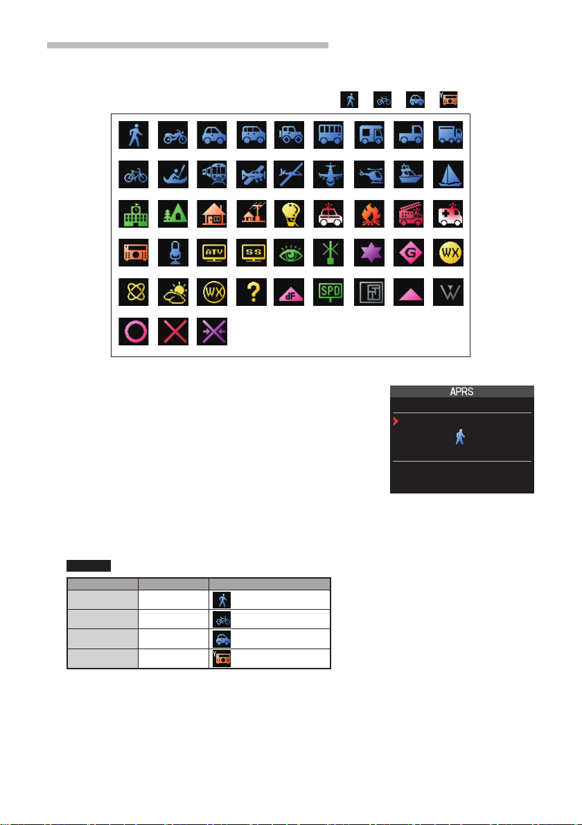
Setting the symbol of your own station
This sets the transmit symbol of your own station. The symbol can be selected from
among 48 types.
The default setting when shipped from the factory is “
”, “ ”, “ ”, “ ”.
1 Press and hold the [DISP] key → Touch [APRS] → [25 MY SYMBOL].
2 Turn the DIAL to select the symbol
The following four symbol types can be selected as your
own symbol: “ICON 1”, “ICON 2”, “ICON 3” and “ICON 4”.
If “ICON 4” is selected, symbol characters can be input
directly when “25 MY SYMBOL (User)” appears. * See
the following page on how to enter the characters.
25 MY SYMBOL
ICON 1
[ /[ ]
Human/Person
PUSH“DISP”
3 Press the [DISP] key
The cursor will move to the “Code” area of the table below. You can turn the DIAL to
select a frequently used symbol from the symbols shown in the table below).
Remark The default value of each symbol is as follows.
MY SYMBOL Code Symbol
1 [ /[ ]
2 [ /b ]
3 [ /> ]
4 [ YY ]
Human
Bicycle
Car
Yaesu Radio
4 Press the [DISP] key.
The symbol of your own station will be set.
5 Press the PTT.
To exit the set mode and return to the operating screen.
7
Page 9

y Entering a symbol character directly
You can enter a symbol character directly if the symbol that you want is not available.
1 Press and hold the [DISP] key → Touch [APRS] → [25 MY SYMBOL].
2 Turn the DIAL to select “ICON 4”.
3 Press the [DISP] key
The cursor will move to the “Code” area.
Reference If “25 MY SYMBOL (User)” does not appear after pressing the [DISP] key, turn the DIAL
to select “25 MY SYMBOL (User).
4 Press the [DISP] key again
The cursor will move to the Symbol Table ID (character on the left side of the code).
5 Turn the DIAL to select the Symbol Table ID
6 Press the [DISP] key
The cursor will move to the Symbol Code (character on the right side of “Code”).
7 Turn the DIAL to select the Symbol Code
8 Press the [DISP] key
The symbol will be set.
9 Press the PTT.
To exit the set mode and return to the operating screen.
Reference Please refer to “http://aprs.org/symbols/symbolsX.txt” and “http://aprs.org/symbols.html”
for the latest symbol table.
8
Page 10
Receiving APRS® beacons
FTM-400D 04/07
This sets the operating frequency of the APRS before receiving a beacon.
Setting the APRS operating frequency
The customary APRS operating frequency differs depending on the region and country.
In the USA, the usual operating frequency is 144.39 MHz. Therefore, to begin APRS
operations set the Band B frequency to 144.39 MHz.
1 Press the [A/B] key
Switch the operating band to Band B.
The APRS will operate only in Band B. Check that A12 (1200bps) or A96 (9600bps) is
displayed on the right-hand side of the frequency (page 6).
2 Setting the operating frequency
Reference If the baud rate setting in [APRS] → [4 APRS MODEM] is set to 1200 bps or 9600 bps in
Receiving beacons
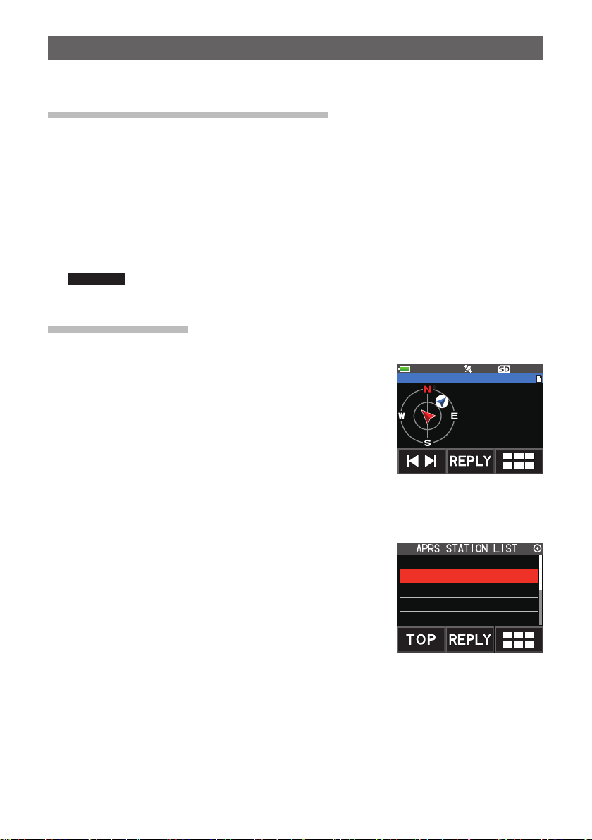
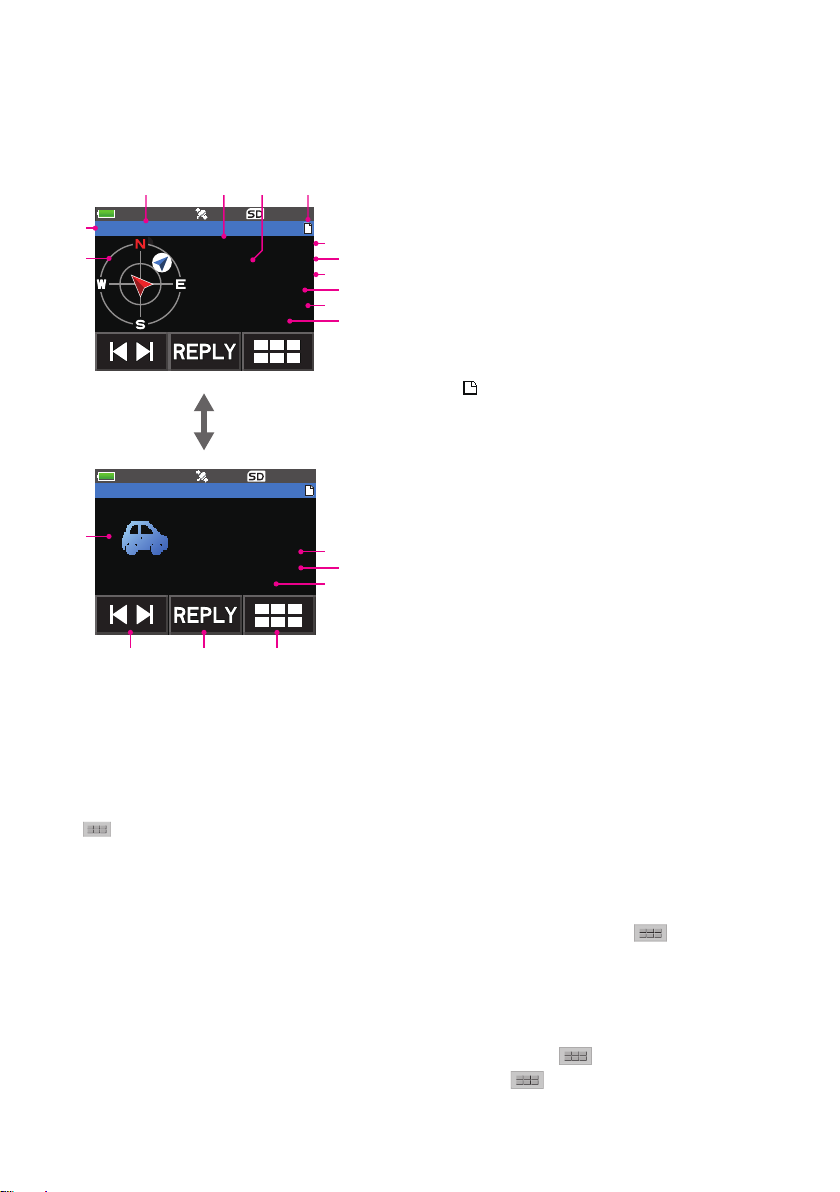
y Displaying beacons in the APRS pop-up screen
A “ping pong” audio alarm will sound when a beacon is
received on the Band B frequency, and the APRS pop-up
screen will be displayed.
The contents displayed in the “APRS POP-UP SCREEN”
and the “APRS STATION LIST DETAIL SCREEN” to be
explained next are basically the same.
the set mode, the receive and save functions will stop automatically.
E JA1ZRL-9
12.5km 15:36
Speed 68km/h
Course 337
Alt 36m
(Off duty)
y Displaying beacons in the APRS STATION LIST detail screen
1 Touch [F MW] → [S.LIST].
The APRS STATION LIST screen will be displayed.
2 Rotate the DIAL knob, to select the beacon whose details
you want to review.
3 Press the [DISP] key to display the details screen.
Turn the DIAL to scroll the screen.
4 Press the [BACK] key.
Returns the screen to the APRS STATION LIST screen.
9
1 E JQ1YBG- 9 15:36
2 E JA6YPC- 7 12:34
3 W JH1YPC-13 04:56
4 E JQ1YBF -9 12/27
5 E JQ1YBG-14 11/18
Page 11

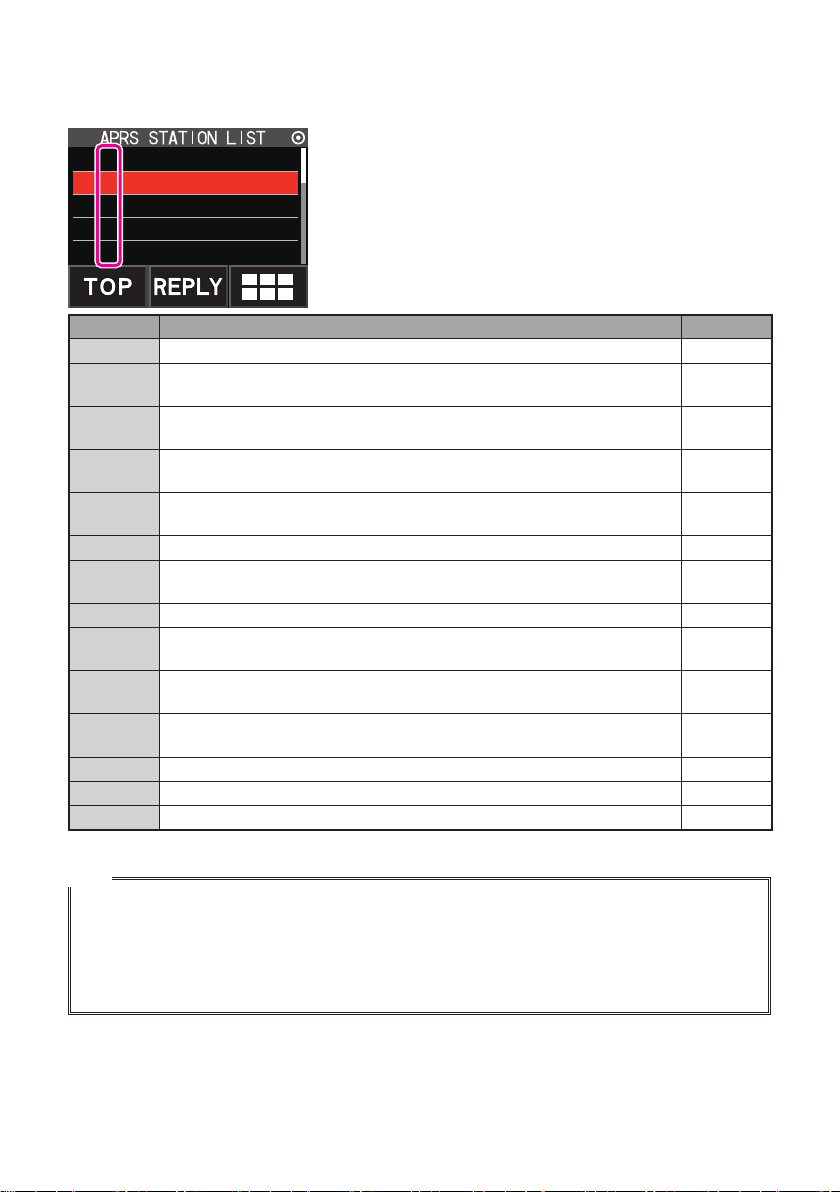
Description of the APRS STATION LIST screen and operations
①
②
③
④ ⑤ ⑥
⑦
⑧
y Description of the APRS STATION LIST screen and operations
①Number: Received beacons (up to a
1 E JQ1YBG- 9 15:36
2 E JA6YPC- 7 12:34
3 W JH1YPC-13 04:56
②Character: The station list characters will be
Refer to the following page for
4 E JQ1YBF -9 12/27
5 E JQ1YBG-14 11/18
:
⑥
⑦Beacon auto / manual transmission icon:
Do not display (MANUAL), Display “
⑧Time or date: Time (HH:MM) or date (MM/DD) will be displayed. The time display will change the date
• Scroll the screen…Turn the DIAL.
• Move to the APRS MESSAGE LIST screen (page 31)…Touch
[M.LIST].
• Replying messages (page 38)…Touch [REPLY].
• Move the cursor to the top of the APRS STATION LIST…Touch [TOP].
• Delete a selected beacon station from the display (page 24)…Touch
by [DEL].
• Move to the “APRS STATION LIST” detail screen (page 12 - page 20)…Turn
the DIAL to select the beacon whose details you want to see and press the [DISP] key.
• Set mode (page 42)… Press the [DISP] key for one second or longer.
•
Manual transmission of a beacon (page 25)…Touch followed by [BEACON TX].
Touch this icon to display the function expansion key screen. Touch this when replying to a
message or moving to the APRS MESSAGE LIST screen and so on.
(page 25)
display on the following day.
③Station name: The call sign or object name / item
④[TOP]: Touch this icon to move to the top
⑤[REPLY]: Touch this icon to display the
” (AUTO) (page 25), Display “ ” (SMART)
maximum of 60) will be displayed,
starting with the most recent one
received.
displayed.
details.
name of the received beacon will
be displayed.
of the list.
“reply message” text input screen.
followed by
followed
Tips
• When [APRS] → [3 APRS FILTER] is set to on, a received beacon matching the filter setting will be
captured and shown on the display. If “OFF” is selected, a “beep” will sound and the beacon will not
be captured or shown.
• The receive audio (beacon or voice etc.) of Band [B] when APRS is operating may be muted by
setting [APRS] → [8 APRS MUTE] in the set mode.
• The reception of an APRS beacon is notified by a ringing sound set in [APRS] → [10 APRS RINGER]
in the set mode. If “OFF” is selected, no audio alarm will sound upon receiving a beacon.
10
Page 12
y Description of Station List Designators
Examples of 14 types of station list designators are described here. Refer to the description
page listed on the table for the detail screen.
1 E JQ1YBG- 9 15:36
2 E JA6YPC- 7 12:34
3 W JH1YPC-13 04:56
4 E JQ1YBF -9 12/27
5 E JQ1YBG-14 11/18
Display Description Page
E Mic-E: Displayed when a beacon of a microphone encoder station is received 12
Position: Displayed when the beacon from a fixed station (FIXED) or a mobile
P
station (MOVING) is received
Position: Displayed when the beacon of a fixed station (FIXED) or a mobile
p
station (MOVING) is received (compression type)
Weather report: Displayed when the beacon of a meteorological station is
W
received
Weather report: Displayed when the beacon of a meteorological station is
w
received (compression type)
O Object: Displayed when the beacon of an object station is received 18
Object: Displayed when the beacon of an object station is received
o
(compression type)
I Item: Displayed when the beacon of an item station is received 18
Item: Displayed when the beacon of an item station is received (compression
i
type)
Killed Object/Item: Displayed when a deleted object station or item station is
K
received
Killed Object/Item: Displayed when a deleted object station or item station is
k
received (compression type)
S Status: Displayed when the beacon of a status station is received 19
? Other: Displayed when a beacon that cannot be interpreted is received 20
Emg Displayed when an emergency signal from a Mic-E station is received 12
13-15
16
17
17
18
18
18
18
Tips
• When the transceiver is turned ON, if the detail screen is displayed before the GPS satellites are
acquired, the position arrow and distance will not be displayed.
• If GPS satellite information is no longer available due to obstructions such as buildings, tunnels,
etc., the most recently acquired coordinates (position arrow, latitude / longitude, distance) will be
displayed. The accurate position information will be displayed again when you move to a position
that can be located.
11
Page 13
①
②
③ ④ ⑤ ⑥
⑧
⑩
⑫
⑰ ⑱ ⑲
⑭
⑯
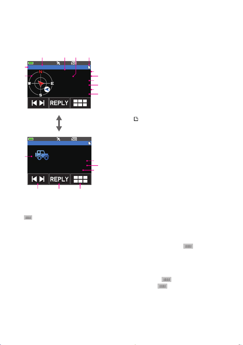
y Explanation of the detail screen display in an Enc (Mic-E) APRS STATION LIST
and description of operations
Turn the DIAL in the APRS STATION LIST screen to select the “E” station and press the
[DISP] key to display the Enc (Mic-E) detailed screen.
Turn the DIAL to scroll the screen.
①Character: The station list characters will be displayed.
②Compass (position):
E JA1ZRL-9
FTM-400D 04/07
12.5km 15:36
Speed 68km/h
Course 337
Alt 36m
(Off duty)
Turn the DIAL
E JA1ZRL-9
Course 337
Alt 36m
(Off duty)
N 3437.24
E 13944.96
[ STATUS TEXT ]
⑭Longitude: The E (east longitude) or W (west longitude) of the current position will be displayed (DDMM.MM or DDMMSS).
⑮STATUS TEXT:
The comments information will be displayed.
⑯Symbol: The symbol of the radio station will be displayed.
⑰[ ❘◄ ►❘ ]: Each time the icon is touched, the function of the DIAL changes.
⑱[REPLY]: Touch this icon to display the reply message text input screen.
: Touch this icon to display the function expansion key screen. Touch this when replying to a message or when
⑲
displaying RAW data etc.
�
�
The direction of the partner station as seen from your own
⑦
③Call sign: The received station call sign will be displayed.
④Type code: The type code used by the partner station will be displayed
⑨
⑪
⑤Distance: Distance to the received station will be displayed.
⑥Message display:
When a beacon containing STATUS TEXT is received, the
⑦Date: The date the beacon was received (MM/DD) will be
⑧Time: The time the beacon was received (HH:MM) will be
⑨Speed: The moving speed of the partner station will be displayed.
⑩Direction: The direction of movement of the partner station will be
⑪Altitude: The altitude of the partner station will be displayed.
⑬
⑫Position comment:
The position comments of the partner station will be
⑮
When an emergency message is received, the message
⑬Latitude: The N (north latitude) or S (south latitude) of the current
station will be displayed.
(Mic-E, McE-Trk, McE-Msg and model name of the radio,
etc.)
” mark is displayed.
“
displayed.
displayed.
displayed.
displayed.
(Emergency!) is displayed and a “pu... x12)” sound will be
repeated 12 times.
position will be displayed (DDMM.MM or DDMMSS).
• Scroll the screen…Turn the DIAL.
• Switching beacon stations…Touch [ ❘◄ ►❘ ] and turn the DIAL.
•
Move to the APRS MESSAGE LIST screen (page 31)…Touch followed by
[M.LIST].
• Replying messages (page 38)…Touch [REPLY].
• Move to the APRS STATION LIST screen (page 10)…Press the [BACK] key.
• Set mode (page 42)…Press the [DISP] key for a second or longer.
• Move to the RAW data display screen (page 23)…Touch
•
Manual transmission of a beacon (page 25)…Touch followed by [BEACON TX].
followed by [RAW].
12
Page 14
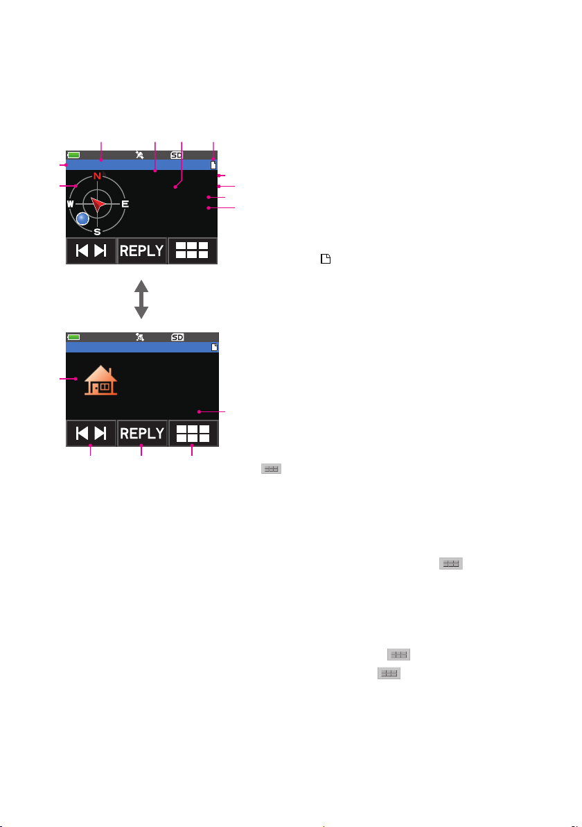
y Explanation of the detail screen display in a P (Position: Fixed station) APRS
①
②
③ ④ ⑤ ⑥
⑧
⑩
⑬ ⑭ ⑮
⑫
STATION LIST and description of operations
Turn the DIAL in the APRS STATION LIST screen to select the “P” station and press the
[DISP] key to display the P (Position) detailed screen.
Turn the DIAL to scroll the screen.
①Character: The station list characters will be displayed.
②Compass (position) :
P JA1ZRL-9
FIXED 04/07
22.5km 15:36
N 3437.24
E 13944.96
Turn the DIAL
P JA1ZRL-9
E 13944.96
[ COMMENT TEXT ]
�
�
�
The direction of the partner station as seen from your own
⑦
③Call sign: The reception call sign will be displayed.
④Partner station information:
⑨
The fixed station information (FIXED) will be displayed.
⑤Distance: Distance with the partner station will be displayed.
⑥Message display:
When a beacon containing STATUS TEXT is received, the
⑦Date: The date the beacon was received (MM/DD) will be
⑧Time: The time the beacon was received (HH:MM) will be
⑨Latitude: The N (north latitude) or S (south latitude) of the current
⑩Longitude: The E (east longitude) or W (west longitude) of the current
⑪COMMENT TEXT:
The comment’s information will be displayed.
⑫Symbol: The symbol of the radio station will be displayed.
⑪
⑬[ ❘◄ ►❘ ]: Each time the icon is touched, the function of the DIAL
⑭[REPLY]: Touch this icon to display the reply message text input
⑮
station will be displayed.
” mark is displayed.
“
displayed.
displayed.
position will be displayed (DDMM.MM or DDMMSS).
position will be displayed (DDMM.MM or DDMMSS).
changes.
screen.
: Touch this icon to display the function expansion key
screen. Touch this when replying to a message or when
displaying RAW data etc.
• Scroll the screen…Turn the DIAL.
• Switching beacon stations…Touch [ ❘◄ ►❘ ] and turn the DIAL.
• Move to the APRS MESSAGE LIST screen (page 31)…Touch
[M.LIST].
• Replying messages (page 38)…Touch [REPLY].
• Move to the APRS STATION LIST screen (page 10)…Press the [BACK] key.
• Set mode (page 42)…Press the [DISP] key for a second or longer.
• Move to the RAW data display screen (page 23)…Touch
• Manual transmission of a beacon (page 25)…Touch
TX].
followed by
followed by [RAW].
followed by [BEACON
13
Page 15
①
②
③ ④ ⑤
⑥
⑧
⑩
⑫
⑱ ⑲ ⑳
⑭
⑰
⑯
y Explanation of the detail screen display in a P (Position: Fixed station) APRS
STATION LIST and description of operations
Turn the DIAL in the APRS STATION LIST screen to select the “P” station and press the
[DISP] key to display the P (Position) detailed screen. Detailed information known as the
PHG code may be included in the position information.
Turn the DIAL to scroll the screen.
①Character: The station list characters will be displayed.
②Compass (position):
P JA1ZRL-9
FIXED 05/24
82.7km 09:36
Power 50W
Height 22m
Gain 6dB
A-Dir 97
Turn the DIAL
P JA1ZRL-9
Gain 6dB
A-Dir 97
P-Rate 4
N 3437.24
E 13944.96
[ COMMENT TEXT ]
⑭Latitude: The N (north latitude) or S (south latitude) of the current position will be displayed (DDMM.MM or DDMMSS).
⑮Longitude: The E (east longitude) or W (west longitude) of the current position will be displayed (DDMM.MM or DDMMSS).
⑯COMMENT TEXT: The comments information will be displayed.
⑰Symbol: The symbol of the radio station will be displayed.
⑱[ ❘◄ ►❘ ]: Each time the icon is touched, the function of the DIAL changes.
⑲[REPLY]: Touch this icon to display the reply message text input screen.
: Touch this icon to display the function expansion key screen. Touch this when replying to a message or when
⑳
displaying RAW data etc.
�
�
The direction of the partner station as seen from your own
⑦
③Call sign: The reception call sign will be displayed.
④Partner station information:
⑨
The fixed station information (FIXED) will be displayed.
⑪
⑤Distance: Distance with the partner station will be displayed.
⑥Message display:
When a beacon containing STATUS TEXT is received, the
⑦Date: The date the beacon was received (MM/DD) will be
⑧Time: The time the beacon was received (HH:MM) will be
⑨Transmission power:
The transmission power of the partner station will be
⑩Antenna ground height:
The antenna ground height of the other station will be
⑬
⑮
⑪Antenna gain: The antenna gain of the partner station will be
⑫Antenna direction: The antenna direction of the partner station will
⑬Transmission count: The transmission count of the partner station
station will be displayed.
” mark is displayed.
“
displayed.
displayed.
displayed.
displayed.
displayed.
be displayed.
will be displayed.
• Scroll the screen…Turn the DIAL.
• Switching beacon stations…Touch [ ❘◄ ►❘ ] and turn the DIAL.
Move to the APRS MESSAGE LIST screen (page 31)…Touch followed by
•
[M.LIST].
• Replying messages (page 38)…Touch [REPLY].
• Move to the APRS STATION LIST screen (page 10)…Press the [BACK] key.
• Set mode (page 42)…Press the [DISP] key for a second or longer.
• Move to the RAW data display screen (page 23)…Touch
Manual transmission of a beacon (page 25)…Touch followed by [BEACON
•
TX].
followed by [RAW].
14
Page 16
①
②
③ ④ ⑤ ⑥
⑧
⑩
⑫
⑮ ⑯ ⑰
⑭
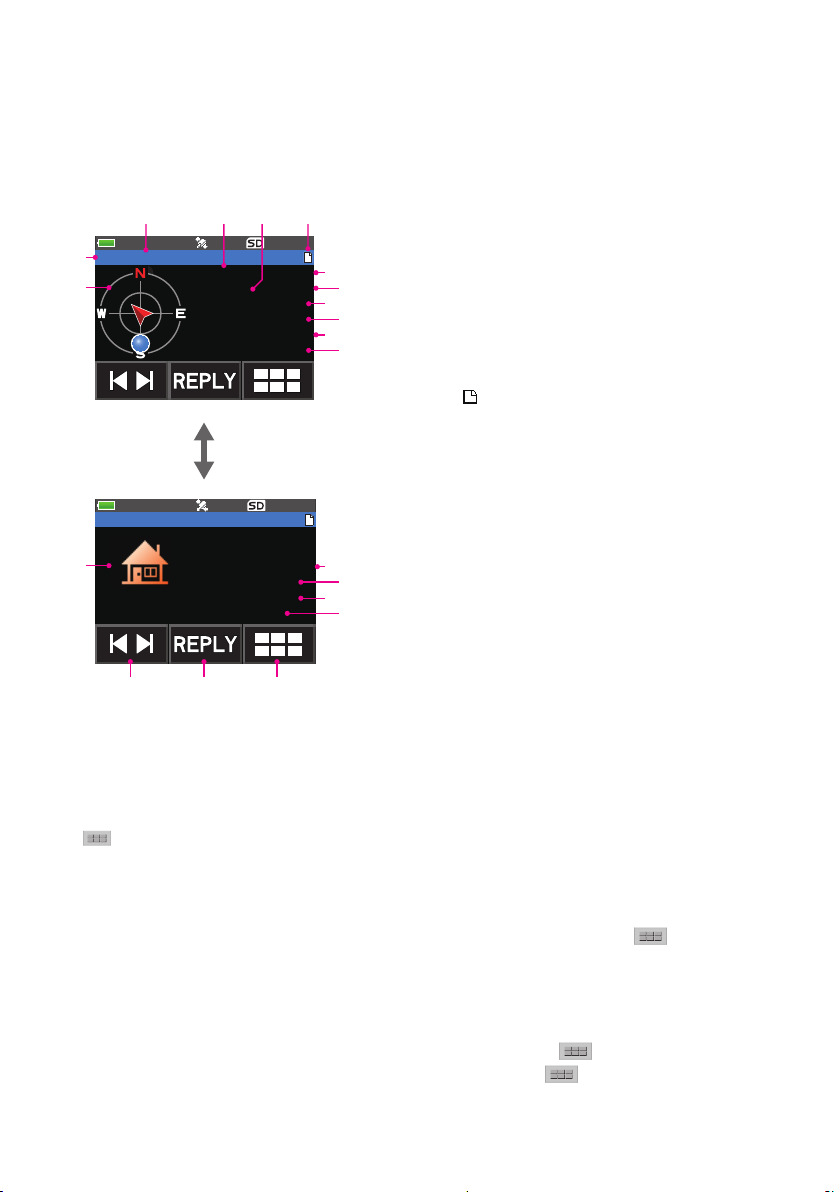
y Explanation of the detail screen display in a P (Position: Fixed station) APRS
STATION LIST and description of operations
Turn the DIAL in the APRS STATION LIST screen to select the “P” station and press
the [DISP] key to display the P (Position) detailed screen. Movement-related information
(Speed, Course), if any, will be displayed as follows.
Turn the DIAL to scroll the screen.
①Character: The station list characters will be displayed.
②Compass (position) :
P JA1ZRL-9
MOVING 06/04
15.1km 18:16
Speed 67km/h
Course 262
N 3437.24
E 13944.96
Turn the DIAL
�
�
P JA1ZRL-9
Course 262
N 3437.24
E 13944.96
�
�
[ COMMENT TEXT ]
• Scroll the screen…Turn the DIAL.
• Switching beacon stations…Touch [ ❘◄ ►❘ ] and turn the DIAL.
• Move to the APRS MESSAGE LIST screen (page 31)…Touch
The direction of the partner station as seen from your own
⑦
③Call sign: The received call sign will be displayed.
④Partner station information:
⑨
The fixed station information (MOVING) will be displayed.
⑪
⑤Distance: Distance to the partner station will be displayed.
⑥Message display:
When a beacon containing STATUS TEXT is received, the
⑦Date: The date the beacon was received (MM/DD) will be
⑧Time: The time the beacon was received (HH:MM) will be
⑨Speed: The moving speed of the partner station will be displayed.
⑩Direction: The direction of movement of the partner station will be
⑪Latitude: The N (north latitude) or S (south latitude) of the current
⑫Longitude: The E (east longitude) or W (west longitude) of the current
⑬
⑬COMMENT TEXT:
The comment’s information will be displayed.
⑭Symbol: The symbol of the radio station will be displayed.
⑮[ ❘◄ ►❘ ]: Each time the icon is touched, the function of the DIAL
⑯[REPLY]: Touch this icon to display the reply message text input
⑰
station will be displayed.
” mark is displayed.
“
displayed.
displayed.
displayed.
position will be displayed (DDMM.MM or DDMMSS).
position will be displayed (DDMM.MM or DDMMSS).
changes.
screen.
: Touch this icon to display the function expansion key
screen. Touch this when replying to a message or when
displaying RAW data etc.
followed by
[M.LIST].
• Replying messages (page 38)…Touch [REPLY].
• Move to the APRS STATION LIST screen (page 10)…Press the [BACK] key.
• Set mode (page 42)…Press the [DISP] key for a second or longer.
• Move to the RAW data display screen (page 23)…Touch
Manual transmission of a beacon (page 25)…Touch followed by [BEACON TX].
•
followed by [RAW].
15
Page 17
①
②
③ ④ ⑤ ⑥
⑧
⑩
⑫
⑰ ⑱ ⑲
⑯
⑭
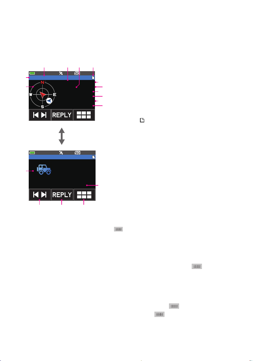
y Explanation of the detail screen display in a p (compressed type: fixed/mobile
station) APRS STATION LIST and description of operations
Turn the DIAL in the APRS STATION LIST screen to select the “p” (Position Compressed
type) station and press the [DISP] key to display the P (Position) detailed screen.
Turn the DIAL to scroll the screen.
①Character: The station list characters will be displayed.
②Compass (position) :
p JA1ZRL-9
fixed 07/01
7.4km 12:06
Speed -km/h
Course -
Range -.-km
Alt 90m
Turn the DIAL
p JA1ZRL-9
Course -
Range -.-km
Alt 90m
N 3437.24
E 13944.96
[ COMMENT TEXT ]
⑯Symbol: The symbol of the radio station will be displayed.
⑰[ ❘◄ ►❘ ]:
⑱[REPLY]:
⑲ : Touch this icon to display the function expansion key screen. Touch this when replying to a message or when
Each time the icon is touched, the function of the DIAL changes.
Touch this icon to display the reply message text input screen.
displaying RAW data etc.
• Scroll the screen…Turn the DIAL.
• Switching beacon stations…Touch [ ❘◄ ►❘ ] and turn the DIAL.
Move to the APRS MESSAGE LIST screen (page 31)…Touch followed by
•
�
�
The direction of the partner station as seen from your own
⑦
③Call sign: The received call sign will be displayed.
④Partner station information:
⑨
The fixed station information (fixed) and mobile station
⑪
⑤Distance: Distance to the partner station will be displayed.
⑥Message display:
When a beacon containing STATUS TEXT is received, the
⑦Date: The date (MM/DD) will be displayed.
⑧Time: The time the beacon was received (HH:MM) will be
⑨Speed: The moving speed of the partner station will be displayed.
⑩Direction: The direction of movement of the partner station will be
⑪Coverage area: Information on the coverage area of the partner
⑬
⑫Altitude: The altitude of the partner station will be displayed.
⑮
⑬Latitude: The N (north latitude) or S (south latitude) of the current
⑭Longitude: The E (east longitude) or W (west longitude) of the current
⑮COMMENT TEXT: The comments information will be displayed.
station will be displayed.
information (moving) will be displayed. Compressed type
information will be displayed in lower case letters.
” mark is displayed.
“
displayed.
displayed.
station will be displayed.
position will be displayed (DDMM.MM or DDMMSS).
position will be displayed (DDMM.MM or DDMMSS).
[M.LIST].
• Replying messages (page 38)…Touch [REPLY].
• Move to the APRS STATION LIST screen (page 10)…Press the [BACK] key.
• Set mode (page 42)…Press the [DISP] key for a second or longer.
• Move to the RAW data display screen (page 23)…Touch
Manual transmission of a beacon (page 25)…Touch followed by [BEACON
•
followed by [RAW].
TX].
16
Page 18
①
②
③ ④ ⑤ ⑥
⑧
⑩
⑫
㉒ ㉓ ㉔
⑲
㉑
⑭
⑰
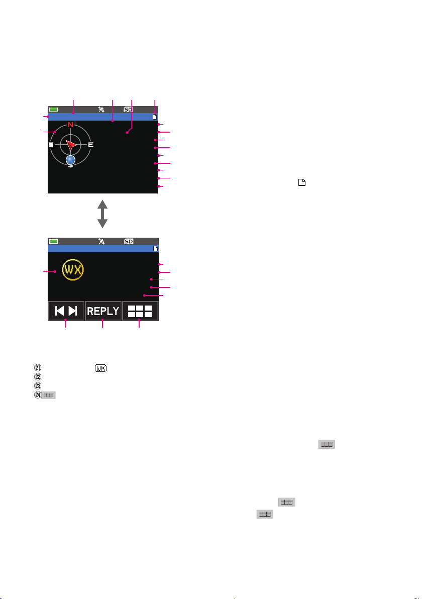
y Explanation of the detail screen display in a W or w (weather report: meteorological
station) APRS STATION LIST and description of operations
Turn the DIAL in the APRS STATION LIST screen to select the “W” (Weather report) or
“w” (Weather report Compressed type) station and press the [DISP] key to display the W
or w (Weather report) detailed screen. Turn the DIAL to scroll the screen.
①Character: The station list characters will be displayed.
②Compass (position): The direction of the partner station as seen
W JA1ZRL-9
WEATHER 03/11
102.7km 14:46
Temp 17C
RainH 1.6mm
RainD 5.8mm
RainN 3.2mm
W-Dir 220
W-Spd 1.6m/s
Gust 3.2m/s
Turn the DIAL
W JA1ZRL-9
Gust 3.2m/s
Baro 990hPa
Humidity 35%
N 3437.24
E 13944.96
[ COMMENT TEXT ]
⑲Longitude: The E (east longitude) or W (west longitude) of the current position will be displayed (DDMM.MM or DDMMSS).
⑳COMMENT TEXT:
Symbol: The symbol will be displayed.
[ ❘◄ ►❘ ]:
[REPLY]:
: Touch this icon to display the function expansion key screen. Touch this when replying to a message or when
The comments information will be displayed.
Each time the icon is touched, the function of the DIAL changes.
Touch this icon to display the reply message text input screen.
displaying RAW data etc.
• Scroll the screen…Turn the DIAL.
• Switching beacon stations…Touch [ ❘◄ ►❘ ] and turn the DIAL.
Move to the APRS MESSAGE LIST screen (page 31)…Touch followed by
•
�
�
③Call sign: The received call sign will be displayed.
⑦
④Partner station information:
The meteorological station (weather) information will be
⑨
⑪
⑤Distance: Distance with the partner station will be displayed.
⑬
⑥Message display: When a beacon containing STATUS TEXT is
⑮
⑦Date: The date (MM/DD) will be displayed.
⑧Time:
⑨Temperature: The temperature information will be displayed.
⑩Rainfall: Information on the rainfall per hour will be displayed.
⑪Rainfall: Information on the rainfall per day will be displayed.
⑫Rainfall: Information on the rainfall from midnight onwards will be
⑬Wind direction: Information on the maximum direction will be
⑯
⑭Wind speed: Wind speed information will be displayed.
⑱
⑮Maximum wind speed: Information on maximum wind speed will
⑳
⑯Atmospheric pressure: Information on the atmospheric pressure
⑰Humidity:
⑱Latitude: The N (north latitude) or S (south latitude) of the current
displayed. Compressed type information will be displayed
in lower case letters.
The time the beacon was received (HH:MM) will be displayed.
displayed.
Information on the humidity will be displayed.
position will be displayed (DDMM.MM or DDMMSS).
from your own station will be displayed.
received, the “ ” mark is displayed.
displayed.
be displayed.
will be displayed
[M.LIST].
• Replying messages (page 38)…Touch [REPLY].
• Move to the APRS STATION LIST screen (page 10)…Press the [BACK] key.
• Set mode (page 42)…Press the [DISP] key for a second or longer.
Move to the RAW data display screen (page 23)…Touch followed by [RAW].
•
•
Manual transmission of a beacon (page 25)…Touch followed by [BEACON TX].
17
Page 19
①
②
③ ④ ⑥ ⑦
⑨
⑪
⑭ ⑮ ⑯
⑬
⑤
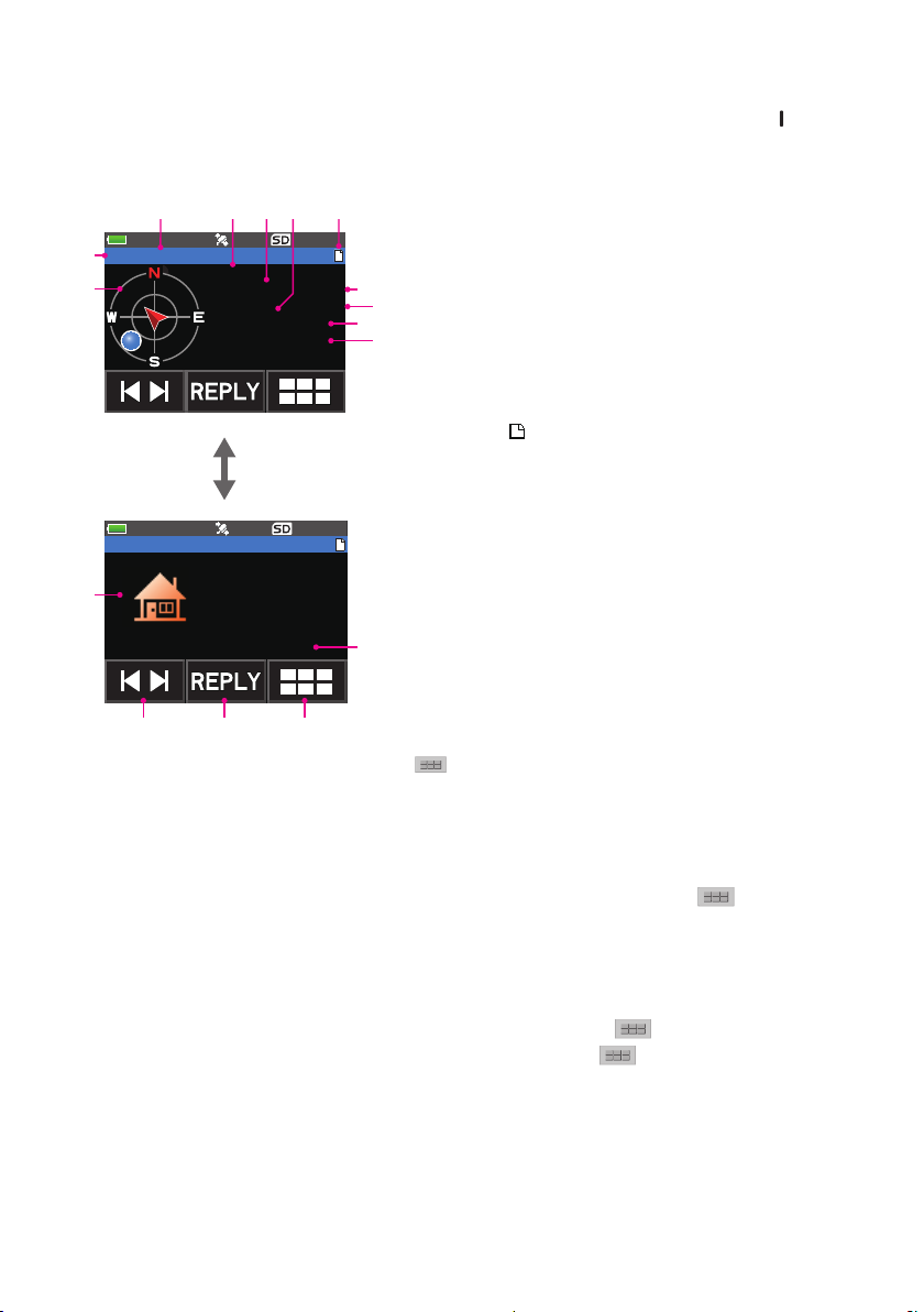
y Explanation of the detail screen display in a O (Object) or I (Item) APRS STATION
LIST and description of operations
Turn the DIAL in the APRS STATION LIST screen to select the “O” (Object) or “
” (Item)
station and press the [DISP] key to display the O (Object) or I (Item) detailed screen.
Turn the DIAL to scroll the screen.
①Character: The station list characters will be displayed.
②Compass (position):
O YAESU
JA1ZRL
OBJECT 02/14
14.7km 20:47
N 3437.24
E 13944.96
Turn the DIAL
O JA1ZRL-9
N 3437.24
E 13944.96
[ COMMENT TEXT ]
�
�
�
�
The direction of the partner station as seen from your own
③Name: The name of the object or item will be displayed.
⑧
④Call sign: The received call sign will be displayed.
⑩
⑤Partner station information:
The fixed station information (OBJECT) will be displayed.
⑥Distance: Distance with the partner station will be displayed.
⑦Message display:
When a beacon containing STATUS TEXT is received, the
⑧Date: The date the beacon was received (MM/DD) will be
⑨Time: The time the beacon was received (HH:MM) will be
⑩Latitude: The N (north latitude) or S (south latitude) of the current
⑪Longitude: The E (east longitude) or W (west longitude) of the current
⑫COMMENT TEXT:
The comments information will be displayed.
⑫
⑬Symbol: The symbol of the radio station will be displayed.
⑭[ ❘◄ ►❘ ]: Each time the icon is touched, the function of the DIAL
⑮[REPLY]: Touch this icon to display the reply message text input
⑯
station will be displayed.
” mark is displayed.
“
displayed.
displayed.
position will be displayed (DDMM.MM or DDMMSS).
position will be displayed (DDMM.MM or DDMMSS).
changes.
screen.
: Touch this icon to display the function expansion key
screen. Touch this when replying to a message or when
displaying RAW data etc.
• Scroll the screen…Turn the DIAL.
• Switching beacon stations…Touch [ ❘◄ ►❘ ] and turn the DIAL.
• Move to the APRS MESSAGE LIST screen (page 31)…Touch
[M.LIST].
followed by
• Replying messages (page 38)…Touch [REPLY].
• Move to the APRS STATION LIST screen (page 10)…Press the [BACK] key.
• Set mode (page 42)…Press the [DISP] key for one second or longer.
• Move to the RAW data display screen (page 23)…Touch
•
Manual transmission of a beacon (page 25)…Touch followed by [BEACON
followed by [RAW].
TX].
18
Page 20

y Explanation of the detail screen display in a S (Status) APRS STATION LIST and
①
② ③ ⑤
⑦
⑨ ⑩ ⑪
④
description of operations
Turn the DIAL in the APRS STATION LIST screen to select the “S” (Status) station and
press the [DISP] key to display the S (Status) detailed screen.
Turn the DIAL to scroll the screen.
①Character: The station list characters will be displayed.
②Call sign: The reception call sign will be displayed.
S JA1ZRL
STATUS 02/14
-.-km 20:47
[ STATUS TEXT ]
....................
....................
....................
③Partner station information:
Status information will be displayed.
⑥
④Distance: Distance with the partner station will not be displayed.
⑤Message display:
⑧
When a beacon containing STATUS TEXT is received, the
⑥Date: The date the beacon was received (MM/DD) will be
⑦Time: The time the beacon was received (HH:MM) will be
⑧STATUS TEXT:
The comments information will be displayed.
⑨[ ❘◄ ►❘ ]: Each time the icon is touched, the function of the DIAL
⑩[REPLY]: Touch this icon to display the reply message text input
: Touch this icon to display the function expansion key
⑪
” mark is displayed.
“
displayed.
displayed.
changes.
screen.
screen. Touch this when replying to a message or when
displaying RAW data etc.
• Scroll the screen…Turn the DIAL.
• Switching beacon stations…Touch [ ❘◄ ►❘ ] and turn the DIAL.
• Move to the APRS MESSAGE LIST screen (page 31)…Touch
followed by
[M.LIST].
• Replying messages (page 38)…Touch [REPLY].
• Move to the APRS STATION LIST screen (page 10)…Press the [BACK] key.
• Set mode (page 42)…Press the [DISP] key for one second or longer.
• Move to the RAW data display screen (page 23)…Touch
• Manual transmission of a beacon (page 25)…Touch
followed by [RAW].
followed by [BEACON
TX].
19
Page 21

y Explanation of the detail screen display in a ? (Other) APRS STATION LIST and
①
② ③ ⑤
⑦
⑨ ⑩ ⑪
④
description of operations
Turn the DIAL in the APRS STATION LIST screen to select the “?” (Other) station and
press the [DISP] key to display the ? (Other) detailed screen.
This is displayed when a packet that cannot be interpreted as an APRS beacon is received.
Turn the DIAL to scroll the screen.
①Character: The station list characters will be displayed.
②Call sign: The reception call sign will be displayed.
JA1ZRL
?
OTHER 03/14
-.-km 20:47
[ DATA TEXT ]
....................
....................
....................
③Partner station information:
Status information will be displayed.
⑥
④Distance: Distance with the partner station will not be displayed.
⑤Message display:
⑧
When a beacon containing STATUS TEXT is received, the
⑥Date: The date the beacon was received (MM/DD) will be
⑦Time: The time the beacon was received (HH:MM) will be
⑧DATA TEXT:
The comments information will be displayed.
⑨[ ❘◄ ►❘ ]: Each time the icon is touched, the function of the DIAL
⑩[REPLY]: Touch this icon to display the reply message text input
: Touch this icon to display the function expansion key
⑪
” mark is displayed.
“
displayed.
displayed.
changes.
screen.
screen. Touch this when replying to a message or when
displaying RAW data etc.
• Scroll the screen…Turn the DIAL.
• Switching beacon stations…Touch [ ❘◄ ►❘ ] and turn the DIAL.
• Move to the APRS MESSAGE LIST screen (page 31)…Touch
followed by
[M.LIST].
• Replying messages (page 38)…Touch [REPLY].
• Move to the APRS STATION LIST screen (page 10)…Press the [BACK] key.
• Set mode (page 42)…Press the [DISP] key for one second or longer.
• Move to the RAW data display screen (page 23)…Touch
• Manual transmission of a beacon (page 25)…Touch
followed by [RAW].
followed by [BEACON
TX].
20
Page 22

Notification of beacon or message arrival in a pop-up screen APRS POPUP function
A notification can be set to appear in a pop-up display when an APRS beacon or message
is received from a partner station.
1 Press and hold the [DISP] key → Touch [APRS] → [9 APRS POPUP].
2 Turn the DIAL to select the item to be set
Refer to the list of set mode actions (page 48) for details of each item.
Mic-E / POSITION / WEATHER / OBJECT / ITEM / STATUS / OTHER / MY PACKET
/ MSG / GRP / BLN / MY MSG / DUP.BCN / DUP.MSG / ACK.REJ / OTHER MSG
3 Press the [DISP] key.
The cursor will move to the set value.
4 Turn the DIAL to select the set value.
OFF: Popup screen is not displayed.
ALL 2 s - ALL 60 s: Sets the display time of a popup for 2 to 60 seconds.
ALL CNT: Popup continues to be displayed until a key is operated.
BND 2 s - BND 60 s: Content is displayed in 2 alphabetic characters on the band
display section on the screen for 2 to 60 seconds. (See page
22).
BND CNT: Content is displayed in 2 alphabetic characters on the band
display section on the screen until a key is operated (See page
22).
“ALL” cannot be selected in MY MSG / DUP.BCN / DUP.MSG / ACK.REJ / OTHER
MSG.
5 Press the [BACK] key.
6 Repeat Step 2 to 5 to set the remaining items.
7 Press the PTT.
To exit the set mode and return to the operating screen.
21
Page 23

Screen when BND 2 s - BND 60 s is selected
If a beacon or message from a partner station arrives when “BND 2 s - BND 60 s” is
selected in the APRS POPUP function, the following screen will be displayed.
A 2-digit letter is displayed
The first two alphabetical characters displayed in front of the call sign of the partner
station contain the following meaning.
First digit
N = New: New signal
D = Duplicate: Received signal
A = ACK: Message ACK signal (page 40)
R = Reject: Message REJ signal (page 34)
Second digit
E = Mic-E: Beacon of a mike encoder station
P = Position: Beacon of a fixed station (FIXED) / mobile station (MOVING)
P = Position: Beacon of a fixed station (fixed) / mobile station (moving) (compression
type)
W = Weather report: Beacon of a meteorological station
w = Weather report: Beacon of a meteorological station (compression type)
O = Object: Beacon of an object station
o = Object: Beacon of an object station (compression type)
I = Item: Beacon of an item station
i = Item: Beacon of an item station (compression type)
K = Killed Object/Item: Deleted object station / item station
k = Killed Object/Item: Deleted object station / item station (compression type)
S = Status: Beacon of a status station
? = Other: Beacon that could not be interpreted
22
Page 24

Audio notification of a beacon or message received
FTM-400D 04/07
APRS RINGER function
An audio notification can be set to sound when an APRS beacon arrives from a partner
station.
1 Press and hold the [DISP] key → Touch [APRS] → [10 APRS RINGER].
2 Turn the DIAL to select the item to be set.
Please refer to the list of set mode actions (page 50) for the details of each item.
Mic-E / POSITION / WEATHER / OBJECT / ITEM / STATUS / OTHER / MY PACKET /
MSG / GRP / BLN / MY MSG / DUP.BCN / DUP.MSG / ACK.REJ / OTHER MSG / TX
BCN / TX MSG
3 Press the [DISP] key.
4 Turn the DIAL to select “ON” or “OFF”.
5 Press the [BACK] key.
6 Repeat Step 2 to 5 to set the remaining items.
7 Press the PTT.
To exit the set mode and return to the operating screen.
Displaying RAW packet data
Display the packet data (raw data) of the partner station from the APRS STATION LIST
detail screen.
1 Touch [F MW] followed by [S.LIST].
The APRS STATION LIST screen will be displayed.
2 Turn the DIAL to select the beacon.
Select the beacon station to confirm the RAW packet data.
3 Press the [DISP] key.
A detail screen of the APRS STATION LIST will appear in the display.
4 Touch followed by [RAW].
The RAW packet data will appear in the display.
Turn the DIAL to scroll the screen display.
5 Touch followed by
screen.
6 Press the
To exit the APRS STATION LIST screen and return to the
operating screen.
[
BACK] key twice.
[
NORMAL] to return to the detail
E JA1ZRL-9
12.5km 15:36
Speed 68km/h
Course 47
Alt 36m
(Off duty)
23
Page 25

Details of RAW packet data display screen
DEST : APNU19
E JA1ZRL-9
①
②
③
①Destination information: View the destination address information of AX.25
②Digipeater information: View the relay station (digipeater) information
③RAW TEXT: View the text of raw data
DIGI(F):
DIGI(L):
[ RAW DATA ]
!3538.17NS13942.34E#
PHG73302/W1 Tkn-N Fi
Tips
• For transmit messages, information on DIGI (First) and DIG (Last) will not be displayed (“-” will be
displayed) as the digipeater information is not saved.
• When a 3rd Party Header Beacon (beacon from I-Gate and others) is received, the route information
included in the text of the 3rd Party Header Beacon will be displayed instead of the information
obtained from the AX.25 packet signal.
Deleting a beacon station from the list
A beacon station which is no longer required can be deleted from the list by selecting it on
the APRS STATION LIST screen.
1 Touch [F MW] followed by [S.LIST].
The APRS STATION LIST screen will be displayed.
2 Turn the DIAL to select the call sign.
Turn the DIAL to select the call sign to delete.
3 Touch followed by [DEL].
A confirmation message “DELETE?” will appear in the display.
Reference Touch “CANCEL” to cancel the deletion.
4 Touch [OK] twice.
The call sign will be deleted from the list.
24
Page 26

Transmitting APRS® beacons
Transmitting a beacon manually
1
Touch [F MW] followed by [BCN-TX] (to display the frequency screen).
Touch
STATION LIST detail screen.
When transmitting a beacon automatically, set the following “Beacon manual / auto
transmission switch” to “AUTO” or “SMART”.
Tips
• If the [DUP BCN] setting under [APRS] → [10 APRS RINGER] is set to ON in the set mode, a “Pee
po po...” alarm will sound when your own station beacon relayed to a digipeater is received.
• When using the GPS function in APRS operations, be sure to check that [APRS] → [24 MY
POSITION] is set to “GPS”. A beacon cannot be transmitted if GPS data cannot be captured.
Switching between automatic and manual beacon transmission
This sets the APRS beacon to auto / manual transmission.
1 Touch [F MW] followed by [S.LIST].
The APRS STATION LIST screen will be displayed.
2 Touch followed by [BEACON]
Each time the [BEACON] is touched, the setting will switch between “MANUAL”,
“AUTO” and “SMART”.
This is a short-cut to [APRS] → [16 BEACON TX] in the set mode.
No display (MANUAL): Only when and [BEACON TX] are
Touch [F MW] followed by [BCN-TX] in
appears (AUTO): Automatically transmit the APRS beacon
appears (SMART): Transmit automatically with the
followed by [BEACON TX] in the APRS STATION LIST screen and APRS
touched will the APRS beacon of your own
station be transmitted (with the default
settings).
the frequency screen.
of your own station at a 5-minute interval.*
SmartBeaconing™ function.*
2
1 E JQ1YBG- 9 15:36
2 E JA6YPC- 7 12:34
3 W JH1YPC-13 04:56
4 E JQ1YBF -9 12/27
5 E JQ1YBG-14 11/18
1
*1: The beacon transmit interval can be changed in the APRS set mode with the [APRS] → [14
BEACON INTERVAL] setting.
*2: Refer to page 26 on the details of the SmartBeaconing™ function.
This setting can be selected only when the status setting of [APRS] → [27 SmartBeaconing] in the
set mode is set to TYPE 1 - TYPE 3, and [APRS] → [24 MY POSITION] is set to GPS.
Tip
The data transmission delay time can be changed using the [APRS] → [12 APRS TX DELAY] setting
in the set mode.
25
Page 27

Setting the automatic beacon transmit interval
This sets the time interval for automatically sending out an APRS beacon.
1 Press and hold the [DISP] key → Touch [APRS] → [14 BEACON INTERVAL].
2 Turn the DIAL to select the automatic transmission interval time.
Select one of the following automatic transmission interval times.
30 sec / 1 min / 2 min / 3 min / 5 min / 10 min / 15 min / 20 min / 30 min / 60 min
Reference Factory shipping value: 5 min
3 Press the PTT.
The automatic transmit interval time will be set and the set mode will be cancelled.
Tips
• When the APRS beacon transmit is changed to [AUTO], the timer for the automatic beacon transmit
interval is reset, and the count for the automatic beacon interval begins. When the set time is reached
the initial beacon will be transmitted.
• Even in [AUTO] beacon transmit, transmission of a beacon may be forced by pressing [F MW]
followed by [BCN-TX] if you are operating in the frequency screen. (if you are in the APRS STATION
LIST screen or APRS STATION LIST detail screen, touch
The automatic transmit timer is reset if the beacon transmit is forced.
• If the squelch is open when the specified time has passed to transmit a beacon, the beacon
transmission is delayed. The beacon will be sent when the squelch is closed.
followed by [BEACON TX] instead).
Setting the SmartBeaconing™
SmartBeaconing™ is a function that efficiently transmits an APRS beacon including your
own station position, speed and direction of travel. The information is based on data from
a GPS satellite receiver unit.
This device supports automatic beacon transmission using SmartBeaconing™.
Three different SmartBeaconing™ settings (TYPE1, TYPE2 and TYPE3) are available.
The default values are preset in advance assuming the following operations:
TYPE1: High speed movement in a car etc.
TYPE2: Medium to low speed movement in a car etc.
TYPE3: Walking at a low speed etc.
TYPE2 and TYPE3 settings (especially TYPE3), multiple beacons are transmitted in a
short time, even if the movement speed is relatively slow. As a result, if these settings
are used directly while traveling at high speed in a vehicle, multiple beacons will be
transmitted, resulting in signal congestion.
When moving at a high speed, be sure to return the setting to TYPE1.
If different timing settings are needed, the TYPE1 - TYPE3 parameters can also be
changed. In order to ensure that beacons can be transmitted in an appropriate manner,
adjust the parameters and DIGI PATH settings of the SmartBeaconing™ function for
efficient operation and reduced signal congestion.
1 Press and hold the [DISP] key → Touch [APRS] → [27 SmartBeaconing].
2 Press the [DISP] key and turn the DIAL to select TYPE.
26
Page 28

Select one of the following TYPEs.
OFF: Turn the SmartBeaconing function OFF
TYPE1: Recommended setting when moving at a high speed in a car etc.
TYPE2: Recommended setting when moving at a low speed such as a bicycle.
TYPE3: Recommended setting when walking at a low speed etc.
27 SmartBeaconing
STATUS : TYPE1
LOW SPD : 5km/h
HIGH SPD : 70km/h
SLOW RATE : 30min
FAST RATE : 120sec
3 Press the PTT.
The selected TYPE is set, and the set mode is cancelled.
4 Touch [F MW] followed by [S.LIST].
The APRS STATION LIST screen will be displayed.
5 Touch followed by [BEACON].
will be displayed at the top right of the display.
This is a short-cut to [APRS] → [16 BEACON TX] in the set mode.
SmartBeaconing is set when
Tips
• If the [APRS] → [16 BEACON TX] setting is set to SMART in the set mode, the setting of the
BEACON INTERVAL will be ignored.
• This function can be selected only when the status of [APRS] → [27 SmartBeaconing] in the set
mode is set to TYPE 1 - TYPE 3, and [APRS] → [24 MY POSITION] is set to GPS.
appears at the top right-hand corner of the display.
*SmartBeaconing™ is a function provided by HamHUD Nichetronix.
27
Page 29

Registering status text
A maximum of up to 60 characters can be registered for 5 types of status comment.
The following characters can be entered.
• Alphabet letter (half-byte upper case, half-byte lower case)
• Number (half-byte)
• Symbol
1 Press and hold the [DISP] key → Touch [APRS] → [15 BEACON STATUS TXT].
2 Turn the DIAL to select “S.TXT” and press the [DISP] key.
3 Turn the DIAL to select “ON” or “OFF”
4 Press the [BACK] key.
5 Turn the DIAL to select “TX RATE” and press the [DISP]
key.
The frequency for transmitting status text when sending an APRS beacon can be set
in TX RATE.
6 Turn the DIAL to select the TX RATE.
Select the rate from 1/1 (every time) to 1/8 (once in 8 times).
7 Press the [BACK] key.
8 Turn the DIAL to select “TEXT” and press the [DISP] key.
9 Turn the DIAL to select the number of the status text to register.
10 Press the [DISP] key.
The screen for editing text will be displayed.
The text contents will be displayed if text was already entered.
Press the [BACK] key to return to the previous screen.
11 Touch [EDIT TEXT].
12 Enter the text.
Refer to “Text input screen” (FT3DR/DE Operating Manual) on how to enter text.
13 Press the PTT.
To exit the set mode and return to the operating screen.
When entering status text, a colon symbol (:) will appear in the 21st, 29th and 43rd
characters. When entering a long text that exceeds the position of this colon, the text
may not be displayed in certain models. Enter a text that is shorter than the colon
position as much as possible.
28
Page 30

Selecting a position comment
This selects the position comment (standard message) to be incorporated into your own
station beacon.
1 Press and hold the [DISP] key → Touch [APRS] → [26 POSITION COMMENT].
2 Turn the DIAL to select the position comment.
Select the position comment from the following list.
Off Duty / En Route / In Service / Returning / Committed / Special / Priority / Custom
0 - Custom 6 / EMERGENCY!
Remark Factory shipping value: Off Duty
Reference Turn the DIAL to select another comment if you want to cancel the selected position
comment.
3 Press the PTT.
The position comment will be registered and returned to the operating screen.
Reference A confirmation message “OK?” will appear and a “poo poo poo” alarm will sound only
Caution
Never select “Emergency!” unless emergency aid is required e.g. accidents and disasters etc.
when “EMERGENCY!” is selected and the PTT is pressed.
Setting the digipeater route
A digipeater is a station that relays packets such as beacons. When using a digipeater,
register the call sign or alias of the digipeater in the radio.
This transceiver is preset to “WIDE1-1” (relay setting of one location) and “WIDE1-1,
WIDE2-1” (relay settings of two locations). When “WIDE 1-1, WIDE 2-1” are selected,
the beacon is initially relayed to the digipeater station at the first location as specified
in WIDE 1-1, and then it is relayed to the digipeater station at the second location as
specified in WIDE 2-1. Under this setting, the beacon is relayed by the digipeater stations
at 2 locations.
In the USA, digipeater stations using APRS customarily operate in the New-Paradigm
format*. Therefore the default settings of this transceiver are configured on the assumption
of a digipeater station operating in the New-Paradigm method.
Select P4 - P8 and enter the call sign and alias if you are using another relay method
(follow the following steps to enter the call sign and alias).
* Refer to the following website for details on the New-N Paradigm method.
http://aprs.org/fix14439.html (as of July 2019).
Caution
When too many relay steps are set, the beacons transmitted from the same station are repeatedly
relayed, resulting in signal congestion on the APRS channel. Use the default settings as far as possible.
29
Page 31

Press and hold the [DISP] key → Touch [APRS] → [18 DIGI PATH].
1
2 Turn the DIAL to select the DIGI PATH.
Select the DIGI PATH from P1 - P8.
P1 (OFF) P2 (WIDE1-1), P3 (1:WIDE1-1/2:WIDE2-1) are
fixed values.
The relay method etc. can be entered for P4 - P8.
Proceed to Step 10 if you select P1 - P3, and Step 3 if
you select P4- P8.
18 DIGI PATH
P1 P2
P3 P4
P5 P6
P7 P8
3 Press the [DISP] key
Switch to the address selection screen.
Press the [BACK] key to return to the previous screen.
4 Turn the DIAL to select the address.
Select the address (1, 2).
8 addresses can be set for P8 only.
5 Press the [DISP] key.
18 DIGI PATH
P8(8):
Address1 ------ Address2 ------ Address3 ------ Address4 -------
6 Enter the call sign using the text input screens.
Refer to “Text input screen” (FT3DR/DE Operating Manual) on how to enter text.
7 Touch [ ].
8 Touch the SSID you want to set.
9 Press the [BACK] key.
The digipeater route will be set.
10 Press the PTT.
To exit the set mode and return to the operating screen.
30
Page 32

APRS® message screen and operating instructions
Description of the APRS MESSAGE LIST screen and operations
Touch [F MW] in the frequency display screen followed by [M.LIST] to display the APRS
MESSAGE LIST screen.
A maximum of 60 received or transmitted messages that have been saved can be
displayed in a list in the APRS MESSAGE LIST screen. The latest message will be
displayed at the top.
Reference Touch followed by [S.LIST] to move to the APRS STATION LIST screen.
①
② ③ ④ ⑤
1 JA1ZRL- 9 15:36
2 JA6YPC- 7 12:34
3 JA1YOE-13 04:56
4 JQ1YBF -9 12/27
5 JQ1YBG-14 11/18
⑥ ⑦ ⑧
③Call sign: The received or transmitted call sign will be displayed.
④Time or date:
The message receive or transmit time (HH:MM) or date (MM/DD) will be displayed.
⑤Beacon auto / manual transmission icon:
If the icon does not appear, beacons are transmitted manually. If the
⑥[TOP]: Touch this to move to the top of the list.
⑦[REPLY]: Touch this to display the screen for writing the reply message.
⑧
beacons are transmitted automatically. If the
transmitted automatically using the SmartBeaconing™ function.
: Touch this to display the function expansion key screen. Touch this when editing a message
or moving to the APRS STATION LIST screen and so on.
①Number: The number of the message received or transmitted
②Receive/Transmit:
One of the following icons is displayed during mes-
. ► Messages transmitted (ACK not received)
4 - 0► Transmission message (transmission not
will be displayed.
sage reception and transmission.
◄ Messages received (unread)
◄ Messages received (read)
► Messages transmitted (ACK received)
complete)
* The figure is the remaining transmission
count
icon is displayed,
icon is displayed, transmissions are
• Scroll the screen…Turn the DIAL.
Move to the APRS STATION LIST screen (page 10)…Touch followed by [S.LIST].
•
• Cancel the transmission settings…Touch followed by [TX CLR].
• Replying messages (page 38)…Touch [REPLY].
• Move the cursor to the top of the APRS MESSAGE LIST…Touch [TOP].
• Delete the selected message from the APRS MESSAGE LIST (page 36)…Touch
followed by [DEL].
• Move to the “APRS MESSAGE LIST” detail screen (page 32)…Turn the DIAL to
select the message whose details you want to see and press the [DISP] key.
Move to the message edit screen (page 33)…Touch followed by [MSG EDIT].
•
• Move to the frequency display screen…Press the [BACK] key
• Set mode (page 42)…Press the [DISP] key for a second or longer.
31
Page 33

Description of the APRS MESSAGE LIST detail screen and operations
③
④
From the APRS MESSAGE LIST screen, turn the DIAL to select the message whose
details you want to see and press the [DISP] key to display the APRS MESSAGE LIST
detailed screen. The APRS MESSAGE LIST detail screen shows the details of the
messages received and transmitted in the APRS MESSAGE LIST screen.
②
①
RX JA1ZRL
MSG 01
*
....................
....................
....................
.......
⑤ ⑥ ⑦
• Switching messages…Touch [ ❘◄ ►❘ ] and turn the DIAL.
• Move to the APRS STATION LIST screen (page 10)…Touch
[S.LIST].
• Cancel the transmission settings…Touch
• Manually send a message…Touch
Move to the message edit screen (page 33)…Touch followed by [MSG EDIT].
•
• Move to the RAW data display screen…Touch followed by [RAW].
• Replying messages (page 38)…Touch [REPLY].
• Move to the APRS MESSAGE LIST screen (page 31)…Press the [BACK] key.
• Set mode (page 42)…Press the [DISP] key for a second or longer.
①RX/TX: Receive details will be displayed if “RX” is selected
②Call sign: The received/transmitted call sign will be displayed.
③Message number:
The message number assigned by the partner
④Message: The contents of the message received will be
⑤[ ❘◄ ►❘ ]: The DIAL function changes each time it is touched.
⑥[REPLY]: Touch this to display the text input screen for writing
⑦
and transmit details will be displayed if “TX” is
selected.
station will be displayed during reception while the
message number assigned by your own station will
be displayed during editing and transmission. The
“GRP: (Group)” and “BLN: (Number/Bulletin Name)”
will be displayed for bulletin and group messages.
displayed.
the reply message.
: Touch this to display the function expansion key
screen. Touch this when editing a message or
moving to the APRS STATION LIST screen and so
on.
followed by
followed by [TX CLR].
followed by [M-TX].
32
Page 34

Message edit screen and description of operations
②
Touch followed by [MSG EDIT] in the APRS MESSAGE LIST detail screen to display
the message edit screen.
You can edit and transmit a received or transmitted message in the message edit screen.
①
To: JA1ZRL
....................
....................
....................
.......
③ ④ ⑤
• Select a standard message…Touch [EDIT TXT] followed by [STANDARD MSG].
• Enter the call sign of your partner station…Touch
• Deleting all messages…Touch
• Move to the frequency display screen…Press the [BACK] key twice.
• Set mode (page 42)…Press the [DISP] key for a second or longer.
Tip
The contents in the edit screen are saved in the editing buffer until the power supply is switched off or
when ALL CLEAR is executed.
①Call sign: The call sign of the destination will be displayed.
②Message: A maximum of up to 67 characters can be entered in
③[M-TX]: Touch this to manually send the message.
④[EDIT TXT]:
Touch this to display the screen for entering the
⑤
a transmission message.
message text.
: Touch this to display the function expansion key
screen. Touch this to delete all messages or to edit
the call sign of the partner station to send to.
followed by [EDIT CS].
followed by [CLR ALL].
33
Page 35

Receiving messages
RX JA1ZRL
When a message is received, a pop-up screen appears, together with a “pee po pee po...”
audio alarm and a flashing strobe (white LED), followed by the screen below.
MSG 01
*
....................
....................
....................
.......
Touch [F MW] in the frequency display screen followed by [M.LIST] to display the APRS
MESSAGE LIST screen.
Reference Touch followed by [S.LIST] to move to the APRS STATION LIST screen.
1 Turn the DIAL to select a received message.
Turn the DIAL to scroll the screen up and down and select a received message.
2 Press the [DISP] key.
The APRS MESSAGE LIST detail screen will appear for you to check the message.
Reference Touch followed by [MSG EDIT] to display the message edit screen.
3 Press the [BACK] key.
Return to the APRS MESSAGE LIST screen.
Tips
• A “pee po pee po pee po...” alarm will sound when a group/bulletin message
is received and the call sign will be displayed as shown in the right screen.
• A “pee...” alarm will sound when a message ACK is received and the “AM>(call sign)” will be displayed
on the screen.
• A “pee....” alarm will sound when a message REJ (reject) is received and the “RM>(call sign)” will be
displayed on the screen.
• The operation of the flashing (white LED) display can be changed by selecting [APRS] → [5 APRS
MSG FLASH] in the set mode.
• The ACK/REJ display can be changed by the [APRS] → [9 APRS POPUP] setting in the set mode.
34
Page 36

Filter setting for messages received
screen
screen
Show the group name such as
The group filter for receiving messages and bulletin messages from specific groups (ALL,
CQ, QST, YAESU etc.) can be set.
1 Press and hold the [DISP] key → Touch [APRS] → [6 APRS MSG GROUP].
2 Turn the DIAL and touch the group filter.
“G1 ALL”, “G2 CQ”, “G3 QST”, “G4 YAESU” and “G5 (any)” can be selected for the
group code.
For bulletin, “B1” to “B3” can be selected.
3 Enter the text.
Refer to “Text input screen” (FT3DR/DE Operating Manual) on how to enter text.
A maximum of up to 9 characters can be entered.
4 Press the PTT.
To exit the set mode and return to the operating screen.
When a group or bulletin message is received, screens like the following are displayed:
RX JA1ZRL
MSG 01
*
Hello...............
....................
....................
.......
Self-addressed message
ALL, CQ, QST, YAESU etc.
RX JA1ZRL
GRP TOURING
Hello...............
....................
....................
.......
Group message reception
RX JA1ZRL
BLN 1 XXXXX
Hello...............
....................
....................
.......
Bulletin reception screen
View bulletin nameBulletin number
Tips
• If the [APRS] → [1 APRS AF DUAL] setting is set to ON in the set mode, the receive audio will
continue to be heard without being interrupted by a received signal in the AF DUAL mode, even if
an APRS beacon or message is received on Band B. Switch to the APRS screen to check APRS
messages and information on received beacons.
• If the [APRS] → [5 APRS MSG FLASH] setting is set to ON in the set mode, a strobe (white LED)
will flash when a message (MSG), group (GRP), or bulletin (BLN) is received.
• The receive audio (beacon or voice etc.) of Band B when the APRS is operating, in can be muted by
setting [APRS] → [8 APRS MUTE] to on in the set mode.
• The display method and time when an APRS beacon is received can be set by the [APRS] → [9
APRS POPUP] setting in the set mode.
• If the MSG in [APRS] → [10 APRS RINGER] is set to ON in the set mode, an audio notification will be
given when a message / group message / bulletin message etc. addressed to your own APRS station
is received. If MSG is set to OFF, the message will appear in the display without any audio alarm.
• Messages that differ only in the SSID that are addressed to your own station call sign can also
be received. However, a reply to the acknowledgment receipt will only be sent if all the characters
including the SSID are the same.
35
Page 37

Deleting a message from the list
Unwanted messages on the APRS MESSAGE screen can also be deleted.
1 Touch [F MW] followed by [M.LIST] in the frequency display screen.
The APRS MESSAGE LIST screen will be displayed.
2 Turn the DIAL to select the message.
Turn the DIAL to select the message to delete.
3 Touch followed by [DEL]
The word “DELETE?” will appear in the display.
Reference Touch [CANCEL] to cancel the deletion.
4 Select [OK] first before touching it
The message will be deleted.
1 JA1ZRL- 9 15:36
2 JA6YPC- 7 12:34
3 JA1YOE-13 04:56
4 J
5 J
Q
1YBF -9 12/27
Q
1YBG-14 11/18
36
Page 38

Transmitting APRS® messages
To: ------
To: JA1ZRL
Creating and sending messages
There are two ways to write a message.
(1) Input the individual characters to write a message
(2) Use fixed texts to create a message
The following characters can be used to enter a message.
• Alphabet letter (half-byte upper case, half-byte lower case)
• Number (half-byte)
• Symbol
y Input individual characters to write a message
1 Touch [F MW] followed by [M.LIST] in the frequency display screen.
The display will change to the APRS MESSAGE LIST screen.
2 Touch followed by [MSG EDIT].
The display will change to the APRS MESSAGE EDIT
screen.
If a previous message was created/edited, the created/
edited message will appear.
1 JA1ZRL- 9 15:36
2 JA6YPC- 7 12:34
3 JA1YOE-13 04:56
4 J
5 J
Q
1YBF -9 12/27
Q
1YBG-14 11/18
3 Touch followed by [EDIT CS]
The display will change to the call sign input screen.
4 Input the call sign in the alphabet input screen and nu-
meric input screen.
Refer to “Text input screen” (FT3DR/DE Operating Man-
ual) on how to enter the call sign of the destination station.
A maximum of 6 digits can be entered for the call sign.
5 Touch [ ].
6 Touch the SSID you want to set.
No setting is required if SSID is not necessary.
7 Press the [BACK] key.
Return to the APRS MESSAGE EDIT screen.
8 Touch [EDIT TEXT].
The screen for editing text will be displayed.
9 Enter the text.
Refer to “Text input screen” (FT3DR/DE Operating
Manual) on how to enter text.
A maximum of up to 67 characters can be entered.
10 Press the [BACK] key.
Return to the APRS MESSAGE EDIT screen.
37
....................
....................
....................
....................
....................
....................
.......
Page 39

11 Touch [M-TX].
To: JA1ZRL
The message will be sent and the display will return to
the frequency screen.
Tip
The data transmission delay time can be changed using the [APRS] → [12 APRS TX DELAY] setting
in the set mode.
y Use fixed text to write a message
A character string registered in advance can be appended to a message text.
Refer to “Registering a standard message” (page 39) for the registration method.
Hello...............
....................
....................
.......
1 Follow Steps 1-8 in “Input individual characters to write a message” (page 37).
2 Touch [MTXT].
A list of fixed text messages will be displayed.
3 Turn the DIAL to select a standard message.
Select a standard message from the list of messages (1-8) registered beforehand.
4 Touch [PASTE].
The selected fixed text will be entered.
You can repeat these steps to continue selecting standard messages.
Reference Characters can also be added to or deleted from a selected standard message.
Characters can also be added before or after a standard message.
5 Press the [BACK] key.
Return to the APRS MESSAGE EDIT screen.
6 Touch [M-TX].
The message will be sent and the display will return to the frequency screen.
Using the reply function
You can also reply to a station that has sent an APRS message.
1 Turn the DIAL to select the partner station
Select the partner station to reply to in the APRS MESSAGE LIST screen.
2 Touch [REPLY]
The display will change to the APRS MESSAGE EDIT screen.
3 Touch [EDIT TEXT]
The screen for editing text will be displayed.
4 Enter the characters
Enter the message according to the procedure in “Input individual characters
to write a message” (page 37) and “Use fixed text to write a message” (page
38).
5 Touch [M-TX]
A reply to the message will be sent to the partner station.
38
Page 40

y Registering a standard message
8 standard messages containing a maximum of 16 characters each can be registered in
this device.
The following characters can be entered in a standard message.
• Alphabet letter (half-byte upper case, half-byte lower case)
• Number (half-byte)
• Symbol
1 Press and hold the [DISP] key → Touch [APRS] → [7 APRS MSG TXT].
2 Turn the DIAL to select the message number to register
and press the [DISP] key.
A screen for editing the fixed text message will be displayed.
3 Entering a fixed text message.
Refer to “Text input screen” (FT3DR/DE Operating Manual) on how to enter a fixed
text message.
A maximum of up to 16 characters can be entered.
4 Press the [BACK] key.
The fixed text message will be registered.
5 Press the PTT.
To exit the set mode and return to the operating screen.
39
Page 41

y Message receipt acknowledgment (ACK)
Show “*” when ACK is received
(display when an acknowledgment is received)
Show the number of remaining transmissions
(when the number of transmissions remaining is four)
Show “
·
” during TX OUT
APRS MESSAGE LIST screen
(display during TX OUT)
When a message is sent to a specific partner station, an ACK packet (receipt acknowledgment)
will be returned to acknowledge receipt of the message by the partner station. The transmission
process ends with an audio alarm to acknowledge receipt when an ACK packet is returned by
the partner station. When an ACK packet is not returned by the partner station for one minute,
the same message will be resent. The status will change to TX OUT if an ACK packet is not
returned by the partner station even after resending the message 5 times. The remaining
transmission count of the acknowledgment receipt will appear in the APRS MESSAGE LIST
screen as shown below. The remaining transmission count can also be checked by pressing
the
[DISP] key
to change to the transmit detail screen.
Remaining count display example
1 JA1ZRL- 9 15:36
2 JA6YPC- 7 12:34
3 JA1YOE-13 04:56
4 J
5 J
APRS MESSAGE LIST screen
Q
1YBF -9 12/27
Q
1YBG-14 11/18
1 JA1ZRL- 9 15:36
4
2 JA6YPC- 7 12:34
3 JA1YOE-13 04:56
4 J
5 J
APRS MESSAGE LIST screen
·
1 JA1ZRL- 9 15:36
2 JA6YPC- 7 12:34
3 JA1YOE-13 04:56
4 J
5 J
Q
1YBF -9 12/27
Q
1YBG-14 11/18
Q
1YBF -9 12/27
Q
1YBG-14 11/18
40
Page 42

Tip
A maximum of 60 messages can be displayed in the APRS screen, with the oldest messages being
deleted automatically if the number exceeds 60. As a result, when a new message is received,
messages that were not resent 5 times may be deleted.
41
Page 43

APRS Set Mode List
Set mode item No./Item Description of function
1 APRS AF DUAL
2 APRS DESTINATION
3 APRS FILTER
4 APRS MODEM
5 APRS MSG FLASH
6 APRS MSG GROUP
7 APRS MSG TXT
8 APRS MUTE
9 APRS POPUP
ON/OFF setting of the audio
when AF Dual Receive is enabled
while APRS function is active.
Display of Model Code. APY03D (cannot be edited) 45
Selecting filter function. Mic-E: ON / OFF
Setting the APRS baud rate. OFF / 1200bps / 9600bps 46
Setting for the strobe flash when
there is an incoming message.
Group filter message receive
settings.
Input of standard message text. 1 to 8 ch 47
Turn on/off the B-band AF muting
function when APRS is set.
Setting the type and time of
messages to display popup.
Selectable Items
(Bold letters: Default)
ON / OFF 45
POSITION: ON / OFF
WEATHER: ON / OFF
OBJECT: ON / OFF
ITEM: ON / OFF
STATUS: ON / OFF
OTHER: ON / OFF
ALTNET: ON / OFF
MSG: 4 sec
OFF / 2 sec - 60 sec /
CONTINUOUS /
EVERY 2 s - 10 m
GRP: 4 sec
OFF / 2 sec - 60 sec /
CONTINUOUS
BLN: 4 sec
OFF / 2 sec - 60 sec /
CONTINUOUS
G1: ALL
G2: CQ
G3: QST
G4: YAESU
G5: --------B1: BLN
B2: BLN
B3: BLN
ON / OFF 47
The Mic-E, POSITION,
WEATHER, OBJECT, ITEM,
STATUS, OTHER, MY PACKET,
MSG, GRP and BLN settings are
as follows.
OFF / ALL 2s to ALL 60s /
ALL CNT / BND 2s to BND 60s /
BNDCNT ALL10s
The MY MSG, DUP.BCN,
DUP.MSG, ACK.REJ, and
OTHER MSG settings are as
follows.
OFF / BND 2s to BND 60s /
BND 10s
Reference
page
45
46
47
48
42
Page 44

Set mode item No./Item Description of function
10 APRS RINGER
11 APRS UNIT
12 APRS TX DELAY
13 BEACON INFO
14 BEACON INTERVAL
15 BEACON STATUS TEXT
16 BEACON TX
17 COM PORT SETTING
Setting the bell sound when
beacon or message is received.
Setting units of the APRS display. POSITION: MM.MM' / MM'SS''
Setting the data sending delay
time.
Setting the transmit beacon
information.
Setting the beacon automatic
transmit interval.
Input setting the status text. S.TXT: ON / OFF
Setting the automatic or manual
beacon transmit.
Setting the COM port. STATUS: ON / OFF
Selectable Items
(Bold letters: Default)
Mic-E: ON / OFF
POSITION: ON / OFF
WEATHER: ON / OFF
OBJECT: ON / OFF
ITEM: ON / OFF
STATUS: ON / OFF
OTHER: ON / OFF
MY PACKET: ON / OFF
MSG: ON / OFF
GRP: ON / OFF
BLN: ON / OFF
MY MSG: ON / OFF
DUP.BCN: ON / OFF
DUP.MSG: ON / OFF
ACK.REJ: ON / OFF
OTHER MSG: ON / OFF
TX BCN: ON / OFF
TX MSG: ON / OFF
DISTANCE: km / mile
SPEED: km/h / knot / mph
ALTITUDE: m / ft
TEMP: °C / °F
RAIN: mm / inch
WIND: m/s / mph
100ms / 150ms / 200ms / 250ms
300ms / 400ms / 500ms / 750ms
1000ms
AMBIGUITY:
OFF / 1 digit / 2 digit / 3 digit
4 digit
SPD / CSE: ON / OFF
ALTITUDE: ON / OFF
30 sec / 1 min / 2 min / 3 min /
5 min / 10 min / 15 min / 20 min /
30 min / 60 min
TX RATE: 1/1 ~ 1/8
TEXT: TEXT1 to TEXT5
AUTO / MANUAL / SMART 54
SPEED: 4800 / 9600 / 19200
/ 38400
INPUT: OFF / GPS
OUTPUT: OFF / GPS / WAY.P
WAYPOINT: NMEA9 / NMEA6 /
NMEA7 / NMEA8
Mic-E: ON / OFF
POSITION: ON / OFF
WEATHER: ON / OFF
OBJECT: ON / OFF
ITEM: ON / OFF
Reference
page
50
51
52
52
53
53
54
43
Page 45

Set mode item No./Item Description of function
18 DIGI PATH
19 GPS SETUP
20 GPS POWER
21 GPS TIME SET
22 GPS UNIT
23 CALLSIGN (APRS)
24 MY POSITION
25 MY SYMBOL
26 POSITION COMMENT
27 SmartBeaconing
28 TIME ZONE
Setting the digipeater route. P1 (FIXED) OFF
Setting the GPS Function datum. DATUM:WGS-84 / Tokyo (Mean)
Setting the GPS function on/off. GPS ON / GPS OFF 57
Setting the GPS time and date
automatic acquisition on/off
function.
Setting units of the GPS display. POSITION: .MMM' / 'SS"
Setting the callsign of your
station.
Setting the position for your
station.
Setting the symbol for your
station.
Setting the position comment
function.
Setting the smart beaconing
function.
Setting the time zone. UTC −13:00 ~ UTC 0:00 ~ UTC
Selectable Items
(Bold letters: Default)
P2 (FIXED) 1 WIDE1-1
P3 (FIXED)
1 WIDE1-1 / 2 WIDE2-1
P4 (2) 1 ・・・・・・ - ・・ / 2・・・・・・ - ・・
P5 (2) 1 ・・・・・・ - ・・ / 2・・・・・・ - ・・
P6 (2) 1 ・・・・・・ - ・・ / 2・・・・・・ - ・・
P7 (2) 1 ・・・・・・ - ・・ / 2・・・・・・ - ・・
P8 (8) 1 ・・・・・・ - ・・ to 8・・・・・ - ・・
PINNING: ON / OFF
DGPS: ON / OFF
AUTO / MANUAL 57
SPEED: km/h / knot / mph
ALTITUDE: m / ft
- - - - - - - - 58
GPS / Manual / P1 to P10 58
Total of 48 icons including
1(/[Human parson]) /
2(/b Bicycle) / 3(/> Car) /
4(YY Yaesu Radios)
Off Duty / En Route
In Service / Returning / Committed
Special / Priority / Custom 0 to 6
EMERGENCY!
STATUS:
OFF / TYPE1 / TYPE2 / TYPE3
LOW SPD:2 ~ 5 ~ 30
HIGH SPD:6 ~ 70 ~ 90
SLOW RATE: 1 ~ 30 ~ 100
FAST RATE: 10 ~ 120 ~ 180sec
TURN ANGL: 5° ~ 28° ~ 90°
TURN SLOP: 1 ~ 26 ~ 255
TURN TIME: 5 ~ 30 ~ 180
+13:00
Reference
page
56
57
58
59
59
59
61
44
Page 46

APRS Set mode function list
y 1 APRS AF DUAL
Receive audio for AF Dual Function
Setting Item: ON / OFF
Default: OFF
Explanation: ON/OFF setting to enable the AF Dual function while APRS function is
active.
y 2 APRS DESTINATION
Model Code Display
Setting Item: [APY03D]
Default: [APY03D]
Explanation: Displays the model code. This setting cannot be changed.
y 3 APRS FILTER
Filter function setting
Setting Item: Mic-E / POSITION / WEATHER / OBJECT / ITEM / STATUS / OTHER /
ALTNET
Default: Mic-E: ON
POSITION: ON
WEATHER: ON
OBJECT: ON
ITEM: ON
STATUS: ON
OTHER: OFF
ALTNET: OFF
Explanation: For setting FILTER for obtaining various beacon types.
ON: Obtains beacons
OFF: Does not obtain beacons
Mic-E: Displays the obtained MIC-Encoder beacons
POSITION: Displays the obtained Position of beacons
WEATHER: Displays the obtained Weather beacons
OBJECT: Displays the obtained Object of beacons
ITEM: Displays the obtained item of beacons
STATUS: Displays the obtained Status of beacons
OTHER: Displays the obtained packets other than those used in APRS.
ALTNET: Displays the obtained packets specified by Destination Address in Alternate
Nets.
45
Page 47

y 4 APRS MODEM
APRS baud rate settings
Setting Item: OFF / 1200bps / 9600bps
Default: OFF
Explanation:
OFF: Turn APRS function [OFF].
1200bps: Sets APRS baud rate to 1200bps.
9600bps: Sets APRS baud rate to 9600bps.
y 5 APRS MSG FLASH
Setting for strobe flash when there is an incoming message.
Setting Item: MSG: OFF / 2 sec - 60 sec / CONTINUOUS / EVERY 2 s - 10 m
GRP: OFF / 2 sec - 60 sec / CONTINUOUS
BLN: OFF / 2 sec - 60 sec / CONTINUOUS
Default: MSG: 4sec. / GRP: 4sec. / BLN: 4sec.
Explanation:
The strobe (white LED) flashes depending on settings in each of the following: [MSG]
when a message is received, [GRP] when a group message is received, [BLN] when a
bulletin message is received.
Strobe (white LED) flashes continuously when COUNTINUOUS is selected.
If the interval is set as Every 2 sec - Every 10 sec in “MSG”, the indicator will blink as
follows.:
Every 2 sec - Every 5 sec 1 flash for the set time interval
Every 6 sec - Every 9 sec 2 flashes for the set time interval
Every 10 sec - Every 50 sec 3 flashes for the set time interval
Every 1 min - Every 5 min 4 flashes for the set time interval
Every 6 min - Every 10 min 5 flashes for the set time interval
The strobe (white LED) will not flash if [OFF] is selected.
When Every 2 sec - Every 10 min is selected in “MSG”, and a GRP (Group) or BLN
(Bulletin) message is received while the light is blinking after receiving a message, the
light of the group or bulletin will blink for a while and then the message light will return to
blinking at the end of the reception.
46
Page 48

y 6 APRS MSG GROUP
Group filter setting for APRS MSG GROUP received messages
Setting Items: A filter can be set for receiving messages with a specified group code
(ALL or CQ).
G1: ALL
G2: CQ
G3: QST
G4: YAESU
G5: -------- B1: BLN
B2: BLN
B3: BLN
Default: G1: ALL
G2: CQ
G3: QST
G4: YAESU
G5: -------- B1: BLN
B2: BLN
B3: BLN
Explanation: A filter can be set to receive messages with a specified group code (ALL
or CQ)
(ALL, CQ, QST, and YAESU are selected in default settings).
“”: Acts as a wild card matching any character received.
y 7 APRS MSG TXT
Entering fixed text characters.
Explanation: 8 types of up to 16 character fixed text can be created, and copied to
messages on the message edit screen.
y 8 APRS MUTE
Band B AF mute ON/OFF setting when configuring the APRS.
Setting Item: ON / OFF
Default: OFF
Explanation: If Set mode option [APRS] → [4 APRS MODEM] is set to 1200bps or
9600bps, received sounds can be muted on the B-band when it is set for
APRS.
If this is set to [OFF], received audio can be heard in accordance to the
volume settings of the APRS band (B-band).
47
Page 49

y 9 APRS POPUP
Setting the popup function for APRS reception
Setting item: Mic-E:
POSITION:
WEATHER:
OBJECT:
ITEM:
STATUS: OFF / ALL 2 s - ALL 60 s / ALL CNT / BND 2 s to BND 60 s / BND CNT
OTHER:
MY PACKET: OFF / ALL 2 s - ALL 60 s / ALL CNT / BND 2 s to BND 60 s / BND CNT
MSG:
GRP:
BLN:
MY MSG: OFF / BND 2 s - BND 60 s
DUP.BCN: OFF / BND 2 s - BND 60 s
DUP.MSG: OFF / BND 2 s - BND 60 s
ACK.REJ: OFF / BND 2 s - BND 60 s
[Explanation on Parameters]
ALL 2 s - ALL 60 s: Sets the display time of a popup for 2 to 60 seconds.
ALL CNT: Popup continues to be displayed until a key is
BND 2 s - BND 60 s: Content is displayed in 2 alphabetic characters on
BND CNT: Content is displayed in 2 alphabetic characters on
Default: Mic-E: ALL 10 s
POSITION: ALL 10 s
WEATHER: ALL 10 s
OBJECT: ALL 10 s
STATUS: ALL 10 s
OTHER: ALL 10 s
MY PACKET: ALL 10 s
MSG: ALL 10 s
GRP: ALL 10 s
BLN: ALL 10 s
MY MSG: BND 10 s
DUP.BCN: BND 10 s
DUP.MSG: BND 10 s
ACK.REJ: BND 10 s
OTHER MSG: BND 10 s
OTHER MSG
OFF / ALL 2 s - ALL 60 s / ALL CNT / BND 2 s to BND 60 s / BND CNT
OFF / ALL 2 s - ALL 60 s / ALL CNT / BND 2 s to BND 60 s / BND CNT
OFF / ALL 2 s - ALL 60 s / ALL CNT / BND 2 s to BND 60 s / BND CNT
OFF / ALL 2 s - ALL 60 s / ALL CNT / BND 2 s to BND 60 s / BND CNT
OFF / ALL 2 s - ALL 60 s / ALL CNT / BND 2 s to BND 60 s / BND CNT
OFF / ALL 2 s - ALL 60 s / ALL CNT / BND 2 s to BND 60 s / BND CNT
OFF / ALL 2 s - ALL 60 s / ALL CNT / BND 2 s to BND 60 s / BND CNT
OFF / ALL 2 s - ALL 60 s / ALL CNT / BND 2 s to BND 60 s / BND CNT
OFF / ALL 2 s - ALL 60 s / ALL CNT / BND 2 s to BND 60 s / BND CNT
: OFF / BND 2 s - BND 60 s
operated.
the band display section on the screen for 2 to 60
seconds. (page 22).
the band display section on the screen until a key is
operated (page 22).
48
Page 50

Explanation:
When an APRS BEACON is received, the content is shown in a POPUP.
This setting is for the method and time the POPUP is displayed.
Mic-E:
POSITION:
WEATHER:
OBJECT:
ITEM:
STATUS:
OTHER:
MY PACKET:
MSG:
GRP:
BLN:
MY MSG:
DUP BCN:
DUP MSG:
ACK REJ:
OTHER MSG:
Setting for the time a POPUP is displayed when a Mic-Encoder beacon is
received.
Setting for the time a POPUP is displayed when a position beacon is received.
Setting for the time a POPUP is displayed when a weather beacon is received.
Setting for the time a POPUP is displayed when a object beacon is received.
Setting for the time a POPUP is displayed when a item beacon is received.
Setting for the time a POPUP is displayed when a status beacon is received.
Setting for the time a POPUP is displayed when a beacon other than what is
used by APRS is received.
Setting for the time a POPUP is displayed when a self transmitted beacon (relay
wave) is received.
Setting for the time a POPUP is displayed when a new message is received.
Setting for the time a POPUP is displayed when a group message is received.
Setting for the time a POPUP is displayed when a bulletin message is received.
Setting for the time a POPUP is displayed when a self transmitted message
(relay wave) is received.
Setting for the time a POPUP is displayed when a overlapping beacon is
received.
Setting for the time a POPUP is displayed when a message that has already
been received, has been received.
Setting for the time a POPUP is displayed when response data of a message
sent by your station is received.
Setting for the time a POPUP is displayed when a message addressed to a
different destination is received.
49
Page 51

y 10 APRS RINGER
Setting the bell sound when a message or beacon is transmitted/received.
Setting item: Mic-E: ON / OFF
POSITION: ON / OFF
WEATHER: ON / OFF
OBJECT: ON / OFF
ITEM: ON / OFF
STATUS: ON / OFF
OTHER: ON / OFF
MY PACKET: ON / OFF
MSG: ON / OFF
GRP: ON / OFF
BLN: ON / OFF
MY MSG: ON / OFF
DUP.BCN: ON / OFF
DUP.MSG: ON / OFF
ACK.REJ: ON / OFF
OTHER MSG: ON / OFF
TX BCN: ON / OFF
TX MSG: ON / OFF
Default: Mic-E: ON
POSITION: ON
WEATHER: ON
OBJECT: ON
ITEM: ON
STATUS: ON
OTHER: ON
MY PACKET: ON
MSG: ON
GRP: ON
BLN: ON
MY MSG: ON
DUP.BCN: ON
DUP.MSG: ON
ACK.REJ: ON
OTHER MSG: ON
TX BCN: ON
TX MSG: ON
Explanation:
Set the bell sound for transmit/receive of APRS beacons and messages and the conditions
for when it rings.
Mic-E: Setting the sound of the bell that rings when a Mic-Encoder beacon is
received.
POSITION: Setting for the sound of the bell that rings when a position beacon is
received.
50
Page 52

WEATHER: Setting for the sound of the bell that rings when a weather beacon is
received.
OBJECT: Setting for the sound of the bell that rings when a object beacon is received.
ITEM: Setting for the sound of the bell that rings when an item beacon is received.
STATUS: Setting for the sound of the bell that rings when a status beacon is received.
OTHER: Setting for the sound of the bell that rings when a beacon other than what
is used by APRS is received.
MY PACKET: Setting for the sound of the bell that rings when a when a self transmitted
beacon (relay wave) is received.
MSG: Setting for the sound of the bell that rings when a new message is received.
GRP: Setting for the sound of the bell that rings when a group message is
received.
BLN: Setting for the sound of the bell that rings when a bulletin message is
received.
MY MSG: Setting for the sound of the bell that rings when a self transmitted message
(relay wave) is received.
DUP BCN: Setting for the sound of the bell that rings when a overlapping beacon is
received.
DUP MSG: Setting for the sound of the bell that rings when a message that has already
has been received is received again.
ACK REJ: Setting for the sound of the bell that rings when response data (ACK, REJ)
of a message sent by your station is received.
OTHER MSG: Setting for the sound of the bell that rings when a message addressed to
another destination is received.
TX BCN: Setting for the sound of the bell that rings when a beacon is being sent
from your station.
TX MSG: Setting for the sound of the bell that rings when a message is being sent
from your station.
y 11 APRS UNIT
Unit setting for APRS display.
Setting item: Position: MM.MM' / MM'SS"
Distance: km / mile
Speed: km/h / knot / mph
Altitude: m / ft
Temp: °C / °F
Rain: mm / inch
Wind: m/s / mph
Default: Depends on the transceiver version.
Explanation:
Set the measurement unit for Latitude/Longitude (Position), Distance, Speed, Altitude,
Temperature (Temp), Precipitation (Rain), and Wind Speed (Wind).
Position: Unit display of minute of Longitude/Latitude (DD° MM.MM’) can be changed.
MM’ is displayed in 1/100 minute and SS” in seconds.
Distance: Unit can be set to [km] or [mile].
51
Page 53

Speed: Unit can be set to [km] or [mile].
APRS beacon transmission content
(data transmission delay time
End Transmission
Hours
Altitude: Unit can be set to [m] or [feet].
Temp: Units can be set to [°C] or [°F].
Rain: Unit can be set to [mm] or [inch].
Wind: Unit can be set to [m/s] or [mph].
y 12 APRS TXDELAY
Set the data sending delay time.
Setting item:
100ms / 150ms / 200ms / 250ms / 300ms / 400ms / 500ms / 750ms / 1000ms
Default: 300ms
Explanation: The preamble (data transmission delay time), shown right, for when
transmitting APRS data can be
set.
Start Transmission
Preamble
(Default: 300ms)
APRS Data
)
y 13 BEACON INFO
Setting the transmit beacon information
Setting item: AMBIGUITY: OFF / 1digi / 2digi / 3digi / 4digi
SPD/CSE: ON / OFF
ALTITUDE: ON / OFF
Default: AMBIGUITY: OFF
SPD/CSE: ON
ALTITUDE: ON
Explanation:
AMBIGUITY: This function is for masking lower denominations of your position
(longitude, latitude) to disambiguate the position of your station.
Setting this function to [OFF] disables disambiguation and transmits
the precise position information of your station.
OFF 1digi 2digi 3digi 4digi
SPD/CSE:
(SPEED/COURSE)
35°38.17’ 35°38.1
139°42.33’ 139°42.3139°42.
If function is set to [ON], speed and directional information is
transmitted. If this function is set to [OFF], speed and directional
35°38.
35°3 .
35°.
139°4 .
139°.
information is not be transmitted.
ALTITUDE: If this function is set to [ON], altitude information is transmitted.
If this function is set to [OFF], altitude information is not transmitted.
52
Page 54

y 14 BEACON INTERVAL
Automatic transmit interval settings for beacon
Setting item: 30 sec / 1 min / 2 min / 3 min / 5 min / 10 min / 15 min / 20 min / 30 min /
60 min
Default: 5 minutes
Explanation:
Set the automatic transmit interval for transmission of APRS beacons.
• Set the Set mode option [APRS] → [16 BEACON TX] to [AUTO]. The timer for
transmission is reset when the automatic transmit interval is set.
From this point, the count for interval time begins, and the initial beacon is automatically
transmitted when the specified time is reached.
• If squelch is active when the interval for automatic beacon transmission is reached, the
transmission is stopped.
The beacon is transmitted when squelch is deactivated.
• If SMART is selected in [APRS] → [16 BEACON TX], the setting for BEACON
INTERVAL is ignored.
y 15 BEACON STATUS TXT
Entering status text
Setting Item: S.TXT: ON / OFF
TX RATE: 1/1 1/2 1/3 1/4 1/5 1/6 1/7 1/8
TEXT1: (Not entered)
TEXT2: (Not entered)
TEXT3: (Not entered)
TEXT4: (Not entered)
TEXT5: (Not entered)
* Up to 60 characters can be entered for status text into TEXT1 to TEXT5.
Default: S.TXT: OFF
TX RATE: 1/1
TEXT1: Text not entered.
Explanation:
S.TXT: Select the status text to send when transmitting a beacon.
Selecting OFF transmits the beacon without a status text.
TX RATE: Set how frequent a status text is sent with a APRS beacon. Select from 1/1:
every time, 1/2: 2 once every 2 transmissions, to up to 1/8: once every 8
transmissions, a status text is sent with a beacon.
53
Page 55

y 16 BEACON TX
Set the automatic beacon transmit interval.
Setting Item: MANUAL / AUTO
/ SMART
Default: MANUAL
Explanation:
Set the method the APRS BEACON is automatically transmitted.
You can also change the transmission method by touching
in the APRS MESSAGE
LIST or APRS STATION LIST screen and then touching the appropriate [BEACON].
MANUAL: Touch [F MW] followed by [BCN-TX] to transmit the APRS BEACON.
Touch
in the APRS STATION LIST screen followed by the [BEACON TX]
to transmit.
AUTO: An APRS BEACON of your station is transmitted automatically according to
BEACON INTERVAL settings.
SMART: A BEACON is automatically transmitted using the SmartBeaconing
TM
function.
This setting can only be selected if: STATUS setting in [APRS] → [27
SmartBeaconing] is set between Type 1 and Type 3, and [APRS] → [24 MY
POSITION] is set to GPS.
y 17 COM PORT SETTING
COM Port setting
Setting Item: STATUS: ON / OFF
SPEED: 4800 / 9600 / 19200 / 38400
INPUT: OFF / GPS
OUTPUT: OFF / GPS / WAY.P
WAYPOINT: NMEA9 / NMEA6 / NMEA7 / NMEA8
Mic-E: ON / OFF
POSIT: ON / OFF
WEATHER: ON / OFF
OBJECT: ON / OFF
ITEM: ON / OFF
Default: STATUS: OFF
SPEED: 9600
INPUT: OFF
OUTPUT: OFF
WAYPOINT: NMEA9
Mic-E: ON
POSIT: ON
WEATHER: ON
OBJECT: ON
ITEM: ON
Explanation:
STATUS: OFF: Set to OFF when data terminal is not in use.
ON: Set to ON when using data terminal.
Various setting items are added when ON is selected.
SPEED: Set the communication speed for the data terminal.
54
Page 56

INPUT: OFF: Deactivate the input function of the data terminal (negate function).
GPS: GPS data is obtained by connecting a commercially sold external GPS
device instead of the internal GPS function in this transceiver.
In this setting, information obtained from the internal GPS function is
negated.
Tip • If an external GPS device is connected to the data terminal, the time display on
the GPS screen appears as shown below.
aa (hour): bb (minute)
• The GPS function in this transceiver uses data in $GPRMC in NMEA-0183
format and $GPGGA data.
In order to use an external GPS device, the device must be able to output data
of this type.
• When using an external GPS device, setting the Set mode option [APRS] →
[20 GPS POWER] to OFF will deactivate the internal GPS function and reduce
battery consumption.
OUTPUT: OFF: Deactivate the input function of the data terminal (negate function).
GPS: Output GPS data ($GPRMC in NMEA-0183 format or $GPGGA
data) obtained by this transceiver.
WAY.P: Output position information from APRS PACKET received from
a BEACON received from another station as WAYPOINT data
($GPWPL in NMEA-0183 format).
WAYPOINT: Set the number of digits for CALLSIGN information of APRS BEACON
stations, attached to various data, when WAYPOINT is selected for
OUTPUT.
NMEA6:
CALLSIGN is restricted to 6 digits to the right (example: if JQ1YBG-14
is received, CALLSIGN information appears as [YBG-14]).
NMEA7:
CALLSIGN is restricted to 7 digits to the right (example: if JQ1YBG-14
is received, CALLSIGN information appears as [1YBG-14]).
NMEA8:
CALLSIGN is restricted to 8 digits to the right (example: if JQ1YBG-14
is received, CALLSIGN information appears as [Q1YBG-14]).
NMEA9:
CALLSIGN is restricted to 9 digits to the right (example: if JQ1YBG-14
is received, CALLSIGN information appears as [JQ1YBG-14]).
Mic-E: ON: Mic-E BEACON information (BEACON displayed as [E] on LIST) is
output with WAPOINT data.
OFF: Mic-E BEACON information is not output when set to OFF.
POSIT: ON: POSITION BEACON information (BEACON displayed as [P] or [p] on
LIST) is output with WAPOINT data.
OFF: POSITION BEACON information is not output when set to OFF.
WEATHER: ON: WEATHER BEACON information (BEACON displayed as [W] or [w]
on LIST) is output with WAPOINT data.
OFF: WEATHER BEACON information is not output when set to OFF.
Tip Because a Positionless type WEATHER BEACON does not have position
information, it does not output WAYPOINT DATA.
OBJECT: ON: OBJECT BEACON information (BEACON displayed as [O] or [o] on
LIST) is output with WAPOINT data.
OFF: POSITION BEACON information is not output when set to OFF.
55
Page 57

ITEM: ON: ITEM BEACON information (BEACON displayed as [I] or [i] on LIST)
is output with WAPOINT data.
OFF: ITEM BEACON information is not output when set to OFF.
Tip
If you are to connect the transceiver with a PC using CT-169, the following settings must be applied
on the PC.
DATA SPEED: 9600bps (the SPEED setting of this transceiver and a PC must correspond).
DATA LENGTH: 8bit
Parity Bit: None
Stop Bit: 1bit
y 18 DIGI PATH
Setting the digipeater route.
Setting item: P1 OFF
P2: WIDE1-1 (fixed value)
P3: WIDE1-1, WIDE2-1 (fixed value)
P4 to P7: Up to 2 addresses can be entered arbitrarily.
P8: Up to 8 addresses can be entered arbitrarily.
Default: P3: FWIDE1-1 AWIDE2-1 (fixed value)
Explanation:
A station that relays packets, such as beacons, is called a digipeater.
Select a CALLSIGN or ALIAS of the digipeater you would like to use.
In this transceiver, [WIDE1-1] (setting for 1 relay station) and [WIDE1-1/WIDE2-1] (setting
for 2 relay stations) is the default.
In [WIDE1-1, WIDE2-1], a transmission is relayed to the first digipeater station specified
as WIDE1-1, then to the second digipeater station specified as WIDE2-1.
In the USA, digipeater stations used by APRS are customarily operated using *NewParadigm.
The initial values set to this transceiver are premised for digipeater stations operating with
New- Paradigm, because most digipeater stations support this method.
In order to use other relay methods, select one of P4 to P8 and enter the CALLSIGN or
ALIAS.
* For information on the New-Paradigm method, refer to the following website for details.
http://aprs.org/fix14439.html
56
Page 58

y 19 GPS SETUP
Setting the GPS Function datum.
Setting Item: DATUM: WGS-84 / Tokyo (Mean)
PINNING: ON / OFF
DGPS: ON / OFF
Default: DATUM: WGS-84
PINNING: ON
DGPS: ON
Explanation:
Select the positioning item of the GPS function.
DATUM: WGS-84: Use WGS-84 as the positioning system. WGS-84 is a global
positioning system constructed and maintained by the US.
TOKYO (Mean): A Japanese positioning system is used as the positioning
system.
* Because APRS uses the DATUM of WGS-88, this setting is not changed
under normal circumstances.
PINNING: ON: The latitude and longitude data is fixed when the movement speed of this
device is 0.
OFF: The latitude and longitude are constantly calculated when the movement
speed of this device is 0.
DGPS: ON: Correction data is used from a geostationary satellite to improve the
accuracy.
OFF: Correction data from geostationary satellites is not used.
y 20 GPS POWER
ON/OFF setting for the GPS function.
Setting Item: GPS ON / GPS OFF
Default: GPS ON
Explanation: Turn the GPS function ON or OFF.
y 21 GPS TIME SET
ON/OFF of the GPS time and date automatic acquisition function.
Setting Item: AUTO / MANUAL
Default: AUTO
Explanation:
AUTO: Time data for the internal clock is automatically obtained from the GPS
function.
MANUAL: GPS time data is not used, and time set manually to the internal clock of this
transceiver is prioritized.
57
Page 59

y 22 GPS UNIT
Unit setting for the GPS display.
Setting item:
Position: .MMM' / 'SS"
Speed: km/h / knot / mph
Altitude: m / ft
Default: Depends on the transceiver version.
Explanation:
Set the measurement unit for Altitude, Speed, Longitude and Latitude (Position).
Position: Unit for Longitude/Latitude can be changed.
MMM is 1/000 minute format. If MMM is SS, unit appear as minute-second
format.
Speed: Unit can be set to [km/h], [mph], or [knot].
Altitude: Unit can be set to [m] or [feet].
y 23 CALLSIGN (APRS)
Specify the CALLSIGN of your station.
Explanation:
Register the CALLSIGN of your station which is needed for APRS communication.
APRS data cannot be transmitted if a CALLSIGN for your station is not registered.
Be sure to register a CALLSIGN.
When a CALLSIGN is registered to your station, it is displayed on the LCD when the
power of this transceiver is turned on.
Register a CALLSIGN as shown below.
– NN
: CALLSIGN (Up to 6 characters)
NN: Number (a number between 1 to 15, or no SSID.)
Entering [–7] after the CALLSIGN is recommended in standard mobile use.
y 24 MY POSITION
Setting the station position.
Setting Item: GPS / Manual / P1 to P10
Default: GPS
Explanation:
Set whether position information for your station is obtained via GPS, or manually entered.
GPS: Acquire the position of your station automatically via GPS.
Manual: Manually set the position of your station.
P1 to P10: Position information of radio stations, acquired via GPS, can be saved in 10
memories (P1 to P10).
Registered position information can be transmitted as data for the current
position of your station with the APRS BEACON.
1 Obtain the position information via GPS.
2 Press the [DISP] key for one second or longer.
The Set Mode Menu will appear.
58
Page 60

3 Touch [APRS].
4 Turn the DIAL to select [24 MY POSITION] and touch it on the display.
5 Turn the DIAL to select the memory to register.
Select a memory channel from P1 to P10, to register the position information.
6 Press the [DISP] key.
7 Touch [P.WRITE]. The position information is registered to the selected
memory channel.
In standard operation of APRS, the position of your station is automatically
acquired via GPS.
Other than when a GPS antenna unit is connected to your station, be sure to
have the setting as “GPS”.
y 25 MY SYMBOL
Symbol setting for your station
Setting Item: Symbol
Default: 1: Human/Person (
2: Bicycle (
3: Car (
4: Yaesu Radios (
Explanation: Set the symbol for your station to transmit.
Select your symbol from 48 types.
y 26 POSITION COMMENT
Set up the position comment function.
Setting Item: Off Duty / En Route / In Service / Returning / Committed / Special / Priority/
Custom 0 / Custom 1 / Custom 2 / Custom 3 / Custom 4 / Custom 5 /
Custom 6 / Emergency!
Default: Off Duty
Explanation: Select the position comment (standard message) incorporated into
beacons of your station.
Unless there is a serious emergency, such as an accident or natural disaster,
do not select [EMERGENCY!].
)
)
)
)
y 27 SmartBeaconing
Settings for SmartBeaconing
Setting Item: STATUS: OFF / TYPE1 / TYPE2 / TYPE3
LOW SPD: 2 to 30
HIGH SPD: 6 to 90
SLOW RATE: 1min to 100min
FAST RATE: 10sec to 180sec
TURN ANGL: 5° to 90°
TURN SLOP: 1 to 255
TURN TIME: 5sec to 180sec
59
Page 61

Default: STATUS: OFF
STATUS TYPE1 TYPE2 TYPE3
LOW SPD 5 3 2
HIGH SPD 70 30 12
SLOW RATE 30min 30min 30min
FAST RATE 120sec 120sec 120sec
TURN ANGL 28° 28° 28°
TURN SLOP 26 11 7
TURN TIME 30sec 30sec 30sec
Explanation:
SmartBeaconing™ is a function that efficiently transmits an APRS beacon including your
own station position, speed and direction of travel. The information is based on data from
a GPS satellite receiver unit.
Set STATUS to TYPE1, TYPE2 or TYPE3; set [APRS] → [24 MY POSITION] to GPS;
and set [APRS] → [16 BEACON TX] to [SMART
function. (Operation is also possible by touching
] to activate the SmartBeaconingTM
in the APRS MESSAGE LIST or
APRS STATION LIST screen and then touching the [BEACON]).
If “
” appears on the top-right corner of the APRS STATION LIST screen,
SmartBeaconing
STATUS: SmartBeaconing
TM
is in operation.
TM
only operates when STATUS is set to TYPE1,
TYPE2, or TYPE3.
Set STATUS to OFF to deactivate SmartBeacon
TM
.
The SmartBeaconing function on this transceiver has 3 different settings
(TYPE 1 to TYPE 3) and has preset initial values postulated to be used in
the following operation.
TYPE1: High speed movement, such as by vehicle.
TYPE2: Medium speed movement, such as by bicycle.
TYPE3: Low speed movement, such as by walking.
TYPE 2 and TYPE 3 settings (particularly TYPE 3) transmits many beacons
in a short period of time even if in comparatively slow movement.
Because of this, using these setting during high speed movement, such
as by vehicle, causes many beacons being transmitted and may cause a
frequency jam.
Be sure to have settings on TYPE1 when in high speed movement.
LOW SPD: If speed is lower than which is set, BEACONs are transmitted in time
intervals set in [SLOW RATE].
The units for speed can be set in Set mode option [APRS] → [11 APRS
UNIT].
HIGH SPD: If speed is higher than which is set, BEACONs are transmitted in time
intervals set in [FAST RATE].
The units for speed can be set in Set mode option [APRS] → [11 APRS
UNIT].
SLOW RATE: BEACON transmission time interval when speed decreases below the
[LOW SPD] setting.
60
Page 62

FAST RATE: BEACON transmission time interval when speed increases above the
[HIGH SPD] setting.
TURN ANGL: Set the minimal value of changes in angle when the direction of movement
changes.
TURN SLOP: Set the coefficient for automatically altering the angle that judges changes
in the direction of movement according to speed.
The higher the coefficient value setting, the greater the judgment angle is
when moving at slow speeds.
1 to 255 (X10)°/SPEED
(If the real number for units of rotating tilt is set to 1/10, this is the same
as the unit setting used in HamHUD Nichetronix, LLC series transceivers.)
TURN TIME: Set the time limit until the next BEACON can be transmitted, after a
BEACON is transmitted upon detection of a change in time (Variable Rate
Beaconing) or direction (Corner Pegging).
Caution
If SmartBeaconingTM is to be operated at different timings, the parameters of settings TYPE1 to TYPE3
can be changed.
When changing parameters, be sure to adjust parameters of SmartBeaconing and DIGI PATH settings
for appropriate beacon transmission intervals to avoid communications channel congestion.
y 28 TIME ZONE
Set the time zone.
Setting Item: ± 13.0 hours
Default: UTC 0:00 hours
Explanation:
The time zone can be set in units of 30 minutes.
Time data from the GPS function is transmitted in Coordinated Universal Time (UTC).
The time difference from UTC varies depending on the country or region. When using
the transceiver in other countries or regions such as when traveling, modify the settings.
61
Page 63

Copyright 2019
YAESU MUSEN CO., LTD.
All rights reserved.
No portion of this manual may be
reproduced without the permission of
YAESU MUSEN CO., LTD.
YAESU MUSEN CO., LTD.
Tennozu Parkside Building
2-5-8 Higashi-Shinagawa, Shinagawa-ku, Tokyo 140-0002 Japan
YAESU USA
6125 Phyllis Drive, Cypress, CA 90630, U.S.A.
YAESU UK
Unit 12, Sun Valley Business Park, Winnall Close
Winchester, Hampshire, SO23 0LB, U.K.
1907-A
 Loading...