

Yaesu FT-2980R Operating Manual
FM TRANSCEIVER
FT-2980R
Operating Manual

Index
Introduction .................................................... 1
About this manual ......................................... 1
Safety Precautions ........................................ 2
Accessories & Options ................................. 4
Supplied Accessories .................................... 4
Optional Accessories .................................... 4
Front Panel Controls & Switches ................. 5
Microphone Switches .................................... 7
Rear Panel Connectors ................................. 8
Installation ...................................................... 9
Preliminary Inspection ................................... 9
Installation Tips ............................................. 9
Antenna Consideration ............................... 10
About coaxial cable ..................................... 10
Mobile Installation ....................................... 10
Base Station Installation ............................. 12
Basic Operation ........................................... 13
Turning the Transceiver On and Off ............ 13
Adjusting the Audio Volume Level ............... 13
Adjusting the Squelch Setting ..................... 13
Frequency Navigation ................................. 14
Transmission ............................................... 15
Advanced Operation ................................... 16
Weather Broadcast Reception (USA Version)
LOCK Feature ............................................. 17
Keyboard Beeper ........................................ 17
Channel Step Selection .............................. 18
Display Brightness ...................................... 18
RF Squelch ................................................. 18
Repeater Operation ..................................... 19
Standard Repeater Shift ............................. 19
Automatic Repeater Shift ............................ 20
Checking the Repeater
Uplink (Input) Frequency .... 20
CTCSS/DCS/EPCS Operation ..................... 21
CTCSS Operation ....................................... 21
DCS Operation ............................................ 23
Tone Search Scanning ................................ 24
EPCS (Enhanced Paging &
Code Squelch) Operation .... 25
CTCSS/DCS/EPCS Bell Operation ............. 27
Split Tone Operation ................................... 27
DTMF Operation ........................................... 28
Manual DTMF Tone Generation .................. 28
DTMF Autodialer ......................................... 28
Memory Operation ....................................... 30
Memory Storage ......................................... 30
Storing Independent Transmit
Frequencies (“Odd Splits”) .... 31
Memory Recall ............................................ 32
Labeling Memories ...................................... 33
... 16
Memory Tuning ........................................... 34
Masking Memories ...................................... 34
Memory Bank Operation ............................. 35
Home Channel Memory .............................. 37
Memory-Only Mode .................................... 37
Scanning ...................................................... 38
Basic Scanner Operation ............................ 38
Scan-Resume Options ................................ 39
Memory Skip Scanning ............................... 39
Preferential Memory Scan .......................... 40
Memory Bank Link Scan ............................. 41
Programmable Band-Scan Limits ............... 41
Priority Channel Scanning (Dual Watch)..... 42
Weather Alert Scan ..................................... 43
Band Edge Beeper ...................................... 43
Smart Search Operation ............................. 44
Internet Connection Feature ....................... 45
SRG (“Sister Radio Group”) Mode .............. 45
FRG (“Friends’ Radio Group”) Mode........... 45
ARTS™ (Automatic Range
Transponder System) .... 48
CW Training Feature .................................... 51
Packet Operation ......................................... 52
Miscellaneous Settings ............................... 53
Password .................................................... 53
Time-Out Timer (TOT) ................................. 54
Automatic Power-Off (APO) ........................ 54
Busy Channel Lock-Out (BCLO) ................. 55
Programming the Key Assignments ............ 56
FM Bandwidth & TX Deviation Level .......... 57
MIC Gain Setting ......................................... 57
DCS Code Inversion ................................... 58
Reset Procedure .......................................... 59
Microprocessor Resetting ........................... 59
Set Mode Resetting .................................... 59
Cloning ......................................................... 60
“Set” (Menu) Mode ...................................... 61
Menu Selection Details ............................... 64
Specifications .............................................. 73
After-market Services ................................. 74
FT-2980R Quick Reference Guide
[
VOL KnOb
Á
Adjusts the audio
volume level.
[
POwer SwItch
À
Press and hold for
one second.
]
[
SQL KnOb
Â
Adjust to the point where the
background noise is muted.
[
FreQuency DIAL KnOb
Ã
Selects the operating Frequency.
]
Press and hold for one second to lock
all key functions except the VOL, SQL
knobs and PTT switch.
[
LOcK SwItch
Ä
]
]
]
[
trAnSMISSIOn SwItch
Å
Speak into the microphone
in a normal voice level while
pressing this switch.
]
[
MIcrOPhOne
]
FT-2980R Quick Reference Guide
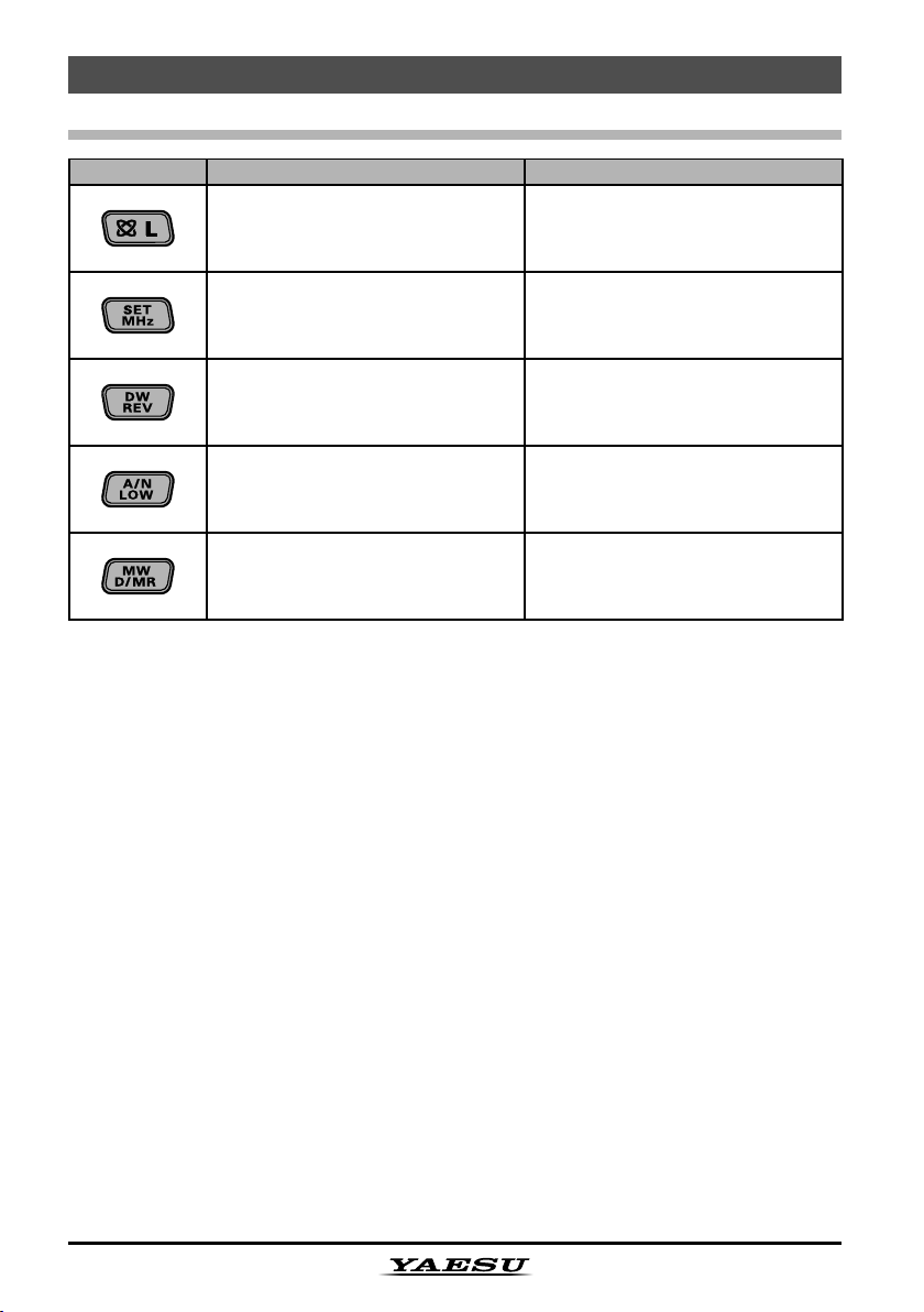
Key Overview
Key Press Key Briey Press and Hold Key
Activates the Internet Connection
Feature.
Allows tuning the VFO frequency
in 1-MHz steps, or tuning channels in 10 channel steps.
Locks out the switches and knobs
(except the VOL, SQL knobs and
PTT switch).
Enters the Set (“Menu”) mode.
Reverses transmit and receive
frequencies in repeater operation.
Selects the transmitter power
output level.
Switches the frequency control
between the VFO, Memory System, and the Home channel.
Activates the Priority Channel
Scanning (Dual Watch feature).
Toggles the display indication between “frequency” and the channel’s “Alpha/Numeric Tag”.
Transfers the VFO contents into
a Memory register.

Introduction
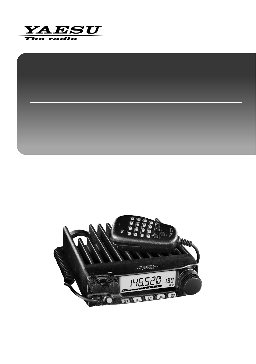
The Yaesu FT-2980R is a deluxe, rugged FM mobile transceiver providing high power
output and outstanding receiver performance for the 144 MHz Amateur band. Included in
the FT-2980R’s feature complement are:
80 Watts of power output, with selection of four power levels for every operating
situation.
Expanded receiver coverage: 136-174 MHz.
Keyboard entry of operating frequencies from the microphone.
Excellent protection from receiver intermodulation distortion, thanks to Yaesu’s
renowned Advanced Track Tuning front end.
221 memories (200 “basic” memory channels, 10 sets of band-edge memory channels,
and one “Home” channel) which can store repeater shifts, odd repeater shifts, CTCSS/
DCS tones, and 6-character Alpha-Numeric labels for easy channel recognition.
10 NOAA Weather Broadcast Channels, with Weather Alert and a Volume Control for
the Weather Alert tone.
Built-in CTCSS and DCS Encoder/Decoder circuits.
The Smart Search
frequencies into dedicated memory banks, is ideal for identifying active repeaters
when visiting a city for the first time.
Extensive Menu system, which allows customization of a number of transceiver
performance characteristics.
The Yaesu-exclusive multi-function LCD display.
Additional features include a transmit Time-Out-Timer (TOT), Automatic Power-Off (APO),
Automatic Repeater Shift (ARS), plus provision for reduction of the Tx deviation in areas
of high channel congestion. And an RF Squelch circuit allows the owner to set the squelch
to open at a programmable setting of the S-Meter, thus reducing guesswork in setting the
squelch threshold.
Congratulations on your purchase of the FT-2980R! Whether this is your first rig, or if
Yaesu equipment is already the backbone of your station, the Yaesu organization is
committed to ensuring your enjoyment of this high-performance transceiver, which should
provide you with many years of satisfying operation. Our dealer network and technical
support personnel stand behind every product we sell, and we invite you to contact us
should you require technical advice or assistance.
We recommend that you read this manual in its entirety prior to installing the FT-2980R,
so that you fully understand the capabilities of your new transceiver.
TM
feature, which automatically sweeps a band and loads active
About this manual
This manual contains symbols and conventions to call attention to important information.
Symbols Description
This icon indicates cautions and alerts the user should be aware of.
This icon indicates helpful notes, tips and information.
1FT-2980R Operating Manual

Safety Precautions
Note beforehand that the company shall not be liable for any damages suffered by the customer or
third parties in using this product, or for any failures and faults that occur during the use or misuse of
this product, unless otherwise provided for under the law.
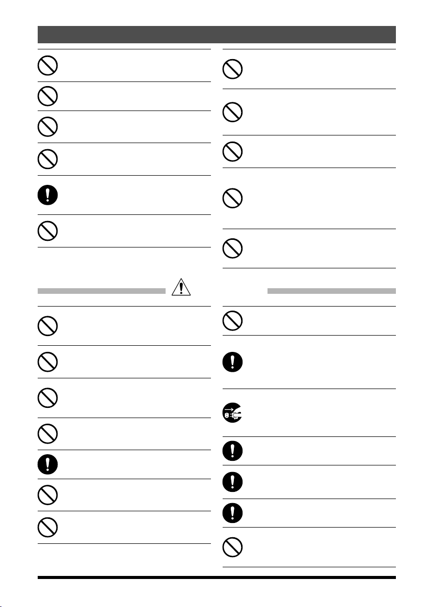
Type and meaning of the marks
This symbol indicates the possibility of death or serious injury being inflicted on the
DANGER
WARNING
CAUTION
user and the surrounding people when these instructions are ignored and the product
is mishandled.
This symbol indicates the possibility of death or serious injury being inflicted on the
user and the surrounding people when these instructions are ignored and the product
is mishandled.
This symbol indicates the possibility of physical impediments occurring or impediments being inflicted on the user and the surrounding people when these instructions
are ignored and the product is mishandled.
Type and meaning of symbols
Prohibited actions that must not be attempted, in order to use this radio safely.
For example,
Precautions that must be adhered to in order to use this radio safely. For example, signifies that the
power supply is to be disconnected.
signifies that disassembly is prohibited.
DANGER
Do not use the device in “regions or aircrafts and vehicles where its use is prohibited” such as in hospitals and airplanes.
This may exert an impact on electronic and
medical devices.
Do not use this product while driving or
riding a motorbike. This may result in accidents.
Make sure to stop the car in a safe location first
before use if the device is going to be used by
the driver.
Never touch the antenna during transmission.
This may result in injury, electric shock and
equipment failure.
Do not operate the device when flammable
gas is generated.
Doing so may result in fire and explosion.
Do not transmit in crowded places in consideration of people who are fitted with
medical devices such as heart pacemakers.
Electromagnetic waves from the device may
affect the medical device, resulting in accidents
caused by malfunctions.
Do not touch any liquid leaking from the liquid display with your bare hands.
There is a risk of chemical burns occurring
when the liquid comes into contact with the skin
or gets into the eyes. In this case, seek medical
treatment immediately.
WARNING
Do not use voltages other than the specified power supply voltage.
Doing so may result in fire and electric shock.
Do not transmit continuously for long periods of time.
This may cause the temperature of the main
body to rise and result in burns and failures due
to overheating.
Do not dismantle or modify the device.
This may result in injury, electric shock and
equipment failure.
Do not handle the power plug and connector etc. with wet hands. Also do not plug
and unplug the power plug with wet hands.
This may result in injury, liquid leak, electric
shock and equipment failure.
2 FT-2980R Operating Manual
When smoke or strange odors are emitted
from the radio, turn off the power and disconnect the power cord from the socket.
This may result in fire, liquid leak, overheating,
damage, ignition and equipment failure. Please
contact our company amateur customer support or the retail store where you purchased
the device.
Keep the power plug pins and the surrounding areas clean at all times.
This may result in fire, liquid leak, overheating,
breakage, ignition etc.
Disconnect the power cord and connection
cables before incorporating items sold separately and replacing the fuse.
This may result in fire, electric shock and
equipment failure.
Safety Precautions
Never cut off the fuse holder of the DC power cord.
This may cause short-circuiting and result in
ignition and fire.
Do not use fuses other than those specified.
Doing so may result in fire and equipment failure.
Do not allow metallic objects such as wires
and water to get inside the product.
This may result in fire, electric shock and
equipment failure.
Do not place the device in areas that may
get wet easily (e.g. near a humidifier).
This may result in fire, electric shock and
equipment failure.
When connecting a DC power cord, pay due
care not to mix up the positive and negative
polarities.
This may result in fire, electric shock and
equipment failure.
Do not use DC power cords other than the
one enclosed or specified.
This may result in fire, electric shock and
equipment failure.
CAUTION
Do not place this device near a heating instrument or in a location exposed to direct
sunlight.
This may result in deformation and discoloration.
Do not place this device in a location where
there is a lot of dust and humidity.
Doing so may result in fire and equipment failure.
Stay as far away from the antenna as possible during transmission.
Long-term exposure to electromagnetic radiation may have a negative effect on the human
body.
Do not wipe the case using thinner and benzene etc.
Please use a soft and dry piece of cloth to wipe
away the stains on the case.
Keep out of the reach of small children.
If not, this may result in injuries to children.
Do not put heavy objects on top of the power cord and connection cables.
This may damage the power cord and connection cables, resulting in fire and electric shock.
Do not transmit near the television and radio.
This may result in electromagnetic interference.
Do not bend, twist, pull, heat and modify the
power cord and connection cables in an unreasonable manner.
This may cut or damage the cables and result
in fire, electric shock and equipment failure.
Do not pull the cable when plugging and
unplugging the power cord and connection
cables.
Please hold the plug or connector when unplugging. If not, this may result in fire, electric
shock and equipment failure.
Refrain from using headphones and earphones at a loud volume.
Continuous exposure to loud volumes may result in hearing impairment.
Do not use the device when the power cord
and connection cables are damaged, and
when the DC power connector cannot be
plugged in tightly.
Please contact YAESU Technical Support or
the retail store where you purchased the device as this may result in fire, electric shock and
equipment failure.
Follow the instructions given when installing items sold separately and replacing the
fuse.
This may result in fire, electric shock and
equipment failure.
Do not use optional products other than
those specified by our company.
If not, this may result in equipment failure.
When using the device in a hybrid car or fuel-saving car, make sure to check with the
car manufacturer before using.
The device may not be able to receive transmissions normally due to the influence of noises from the electrical devices (inverters etc.)
fitted in the car.
For safety reasons, switch off the power
and pull out the DC power cord connected
to the DC power connector when the device
is not going to be used for a long period of
time.
If not, this may result in fire and overheating.
Do not throw or subject the device to strong
impact forces.
This may result in equipment failure.
Do not the put this device near magnetic
cards and video tapes.
The data in the cash card and video tape etc.
may be erased.
Do not turn on the volume too high when
using a headphone or earphone.
This may result in hearing impairment.
Do not place the device on an unsteady or
sloping surface, or in a location where there
is a lot of vibration.
The device may fall over or drop, resulting in
fire, injury and equipment failure.
FT-2980R Operating Manual
3

Safety Precautions
Do not stand on top of the product, and do
not place heavy objects on top or insert objects inside it.
If not, this may result in equipment failure.
Do not use a microphone other than those
specified when connecting a microphone to
the device.
If not, this may result in equipment failure.
Do not touch the heat radiating parts.
When used for a long period of time, the temperature of the heat radiating parts will get
higher, resulting in burns when touched.
Do not open the case of the product except
when replacing the fuse and when installing
items sold separately.
This may result in injury, electric shock and
equipment failure.
Accessories & Options
Supplied Accessories
Microphone MH-48
Mobile Mounting Bracket MMB-83 .................................................................................. 1
DC Power Cord w/Fuse .................................................................................................... 1
Spare Fuse 25A ................................................................................................................ 2
Standing Foot ................................................................................................................... 2
Operating Manual ............................................................................................................. 1
Warranty Card ..................................................................................................................1
A6JA
................................................................................................... 1
Optional Accessories
High-Power External Speaker MLS-100
AC Power Supply FP-1023 (23 A: USA market only)
AC Power Supply FP-1030A
4
FT-2980R Operating Manual
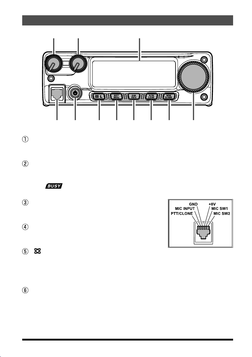
③ ④ ⑤ ⑥ ⑦ ⑧ ⑨ ⑩
① ② ⑪
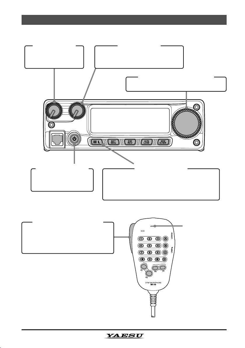
VOL Knob
This control adjusts the audio volume level. Clockwise rotation increases
the volume level.
SQL Knob
This control is used to silence background noise on the receiver. It should
be advanced clockwise just to the point where the noise is silenced (and
the “ ” indicator on the display turns off), so as to provide the best
sensitivity to weak signals.
Microphone Jack
Connect the supplied MH-48
phone to this jack.
PWR Key
Press and hold this key for one second to toggle
the transceiver’s power on and off.
[
(L)]
This key allows operation in conjunction with the Internet Connection feature.
Press and hold in this key for one second to toggle the Lockout Feature “on”
or “off”.
[
MHz(SET
This key allows tuning in 1-MHz steps (the MHz digits will blink on the dis-
play). If receiving on a memory, pressing this key the rst time activates the
Memory Tuning mode, and pressing it again enables 1-MHz steps.
Press and hold in this key for one second to activate the “Set” (Menu)
mode.
Key
)]
Key
Front Panel Controls & Switches
A6J
Hand Micro-
5FT-2980R Operating Manual
Front Panel Controls & Switches
[
REV(DW
During split-frequency operation, such as through a repeater, this key reverses the transmit and receive frequencies.
Press and hold in this key for one second to activate the Dual Watch feature, described in the Operation chapter (“PRI” will be displayed on the
LCD, indicating “Priority Channel” monitoring).
[
LOW(A/N
Press this key momentarily to select the transmitter power output level.
The available power levels are:
LOW1 (5 W) à LOW2 (10 W) à LOW3 (30 W) à HIGH (80 W)
To toggle the display between indication of the frequency and the channel’s
Alpha/Numeric label, press and hold in this key for one second while receiving on that memory channel.
[
D/MR(MW
Press this key momentarily to switch the frequency control among the VFO,
Memory System, and Home channel.
Press and hold in this key for one second to activate the Memory Storage
mode.
)]
)]
Key
Key
)]
Key
DIAL Knob
This 24-position detented rotary switch is used for tuning, memory selection
and most function settings. The microphone [UP]/[DWN] buttons duplicate
the functions of this knob.
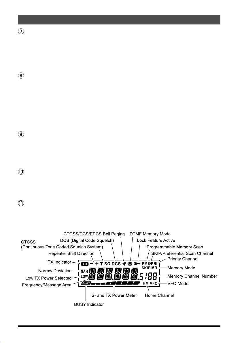
Display
The main digits on the display may show the operating frequency, memory
name, or any of many parameters during Menu setup.
6
FT-2980R Operating Manual

Microphone Switches
⑥
PTT Switch
Press this switch to transmit, and release it to receive.
Keypad
These 16 keys generate DTMF tones
during transmission.
In the receive mode, these 16 keys can
be used for direct frequency entry and/
or direct numeric recall of the Memory
channels.
The [A], [B], [C], and [D] keys, on receive,
replicate the functions of the front
panel keys ([MHz(SET)], [REV(DW)],
[
LOW(A/N)], and [D/MR(MW
the previous discussion.
[P1]/[P2]/[P3]/[P4]
These four keys are user programmable, allowing quick access to features
used often. The default functions are
described below.
[P1]
button (SQL OFF
Press this button to disable the noise and tone squelch systems.
[P2]
button (S SRCH
Press this button to activate the Smart Search feature.
[P3]
button (C SRCH
Press this button to activate the Tone Search feature.
[P4]
button (WX CH/T.CALL
In the USA version, pressing this button recalls the “Weather” broadcast
channel bank. In the Asian version, pressing this button activates T.CALL
(1750 Hz) for repeater access.
You can reprogram the [P1], [P2], [P3], and [P4] buttons for other functions, if desired. See page 56 for details.
Buttons
)
)
)
)])
. See
)
①
②
LAMP Switch
This switch illuminates the Microphone’s keypad.
LOCK Switch
This switch locks out the Microphone’s buttons (except for the keypad and
PTT switch).
[UP]/[
Press (or hold in) either of these buttons to tune (or scan up or down) the
operating frequency or through the memory channels. In many ways, these
buttons emulate the function of the (rotary) DIAL knob.
DWN
]
Button
⑤
④
③
7FT-2980R Operating Manual
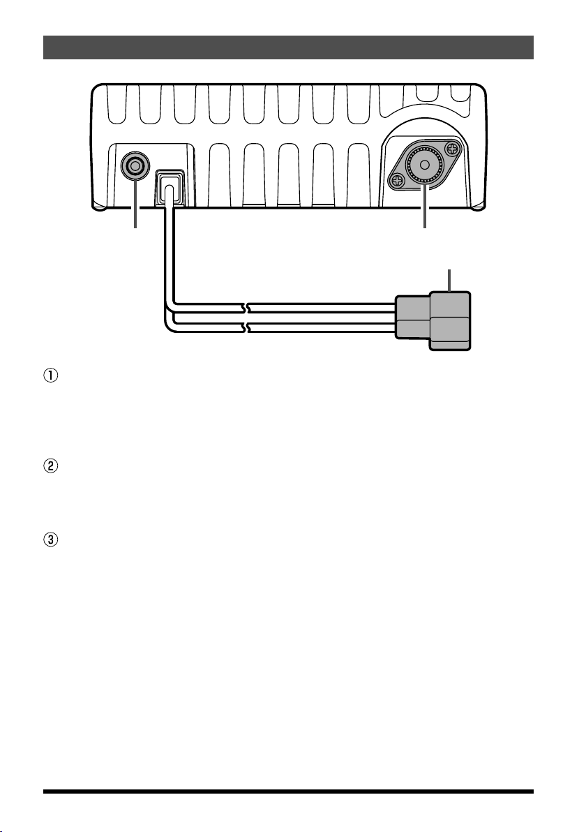
Rear Panel Connectors
②③
①
13.8V DC Cable Pigtail
This is the power supply connection for the transceiver. Use the supplied
DC cable to connect this pigtail to the car battery or other DC power supply
capable of at least 15 Amperes (continuous duty). Make certain that the red
lead connects to the positive side of the supply. The fuse is 25A.
ANT Coaxial Socket
Connect a 144-MHz antenna to this type-M (SO-239) socket using 50-Ohm
coaxial cable and a type-M (PL-259) plug. Make sure the antenna is de-
signed specically for use on the operating frequency.
EXT SP Jack
This 2-contact 3.5-mm mini phone jack provides receiver audio output for
an optional external speaker. The audio impedance is 4 Ohms, and the level varies according to the setting of the front panel’s VOL control. Inserting
a plug into this jack disables audio from the transceiver’s internal speaker.
8 FT-2980R Operating Manual

Installation
This chapter describes the installation procedure for integrating the FT-2980R into a
typical amateur radio station. It is presumed that you possess technical knowledge and
conceptual understanding consistent with your status as a licensed radio amateur. Please
take some extra time to make certain that the important safety and technical requirements
detailed in this chapter are followed closely.
Preliminary Inspection
Inspect the transceiver visually immediately upon opening the packing carton. Confirm
that all controls and switches work freely, and inspect the cabinet for any damage. Gently
shake the transceiver to verify that no internal components have been shaken loose due
to rough handling during shipping.
If any evidence of damage is discovered, document it thoroughly and contact the shipping
company (or your local dealer, if the unit was purchased over-the-counter) so as to get
instructions regarding the prompt resolution of the damage situation. Be certain to save
the shipping carton, especially if there are any punctures or other evidence of damage
incurred during shipping; if it is necessary to return the unit for service or replacement, use
the original packing materials but put the entire package inside another packing carton, so
as to preserve the evidence of shipping damage for insurance purposes.
Installation Tips
To ensure long life of the components, be certain to provide adequate ventilation around
the cabinet of the FT-2980R.
Do not install the transceiver on top of another heat-generating device (such as a power
supply or amplifier), and do not place equipment, books, or papers on top of the FT-
2980R. Avoid heating vents and window locations that could expose the transceiver to
excessive direct sunlight, especially in hot climates. The FT-2980R should not be used in
an environment where the ambient temperature exceeds +140 °F (+60 °C).
9FT-2980R Operating Manual
Installation
Antenna Consideration
The FT-2980R is designed for 50 Ohm resistive impedance at the amateur operating
frequencies.
The antenna (or a 50 Ohm dummy load) should be connected whenever the transceiver is
turned on, to avoid damage that could otherwise result if transmission occurs accidentally
without an antenna.
Ensure that your antenna is designed to handle 80 Watts of transmitter power. Some
magnetic-mount mobile antennas, designed for use with hand-held transceivers, may
not be capable of withstanding this power level. Consult the antenna manufacturer’s
specification sheet for details.
Construct the antenna and coaxial cable, to maintain the impedance presented to the FT-
2980R antenna connector for an SWR of 1.5 or less. Careful preparation of the antenna
will permit maximum performance and protect the transceiver from damage. High voltages
may be present on the antenna; install it so it will not be easily touched when in operation.
About coaxial cable
Use high-quality 50-Ohm coaxial cable for the lead-in to your FT-2980R transceiver.
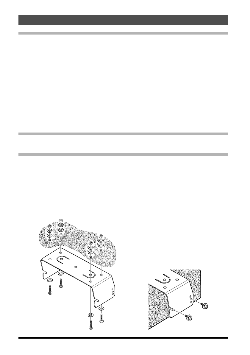
Mobile Installation
The FT-2980R must only be installed in vehicles having a 13.8 Volt negative ground
electrical system. Mount the transceiver where the display, controls, and microphone are
easily accessible, using the supplied MMB-83 mounting bracket.
The transceiver may be installed in almost any location, but should not be positioned
near a heating vent nor anywhere where it might interfere with driving (either visually or
mechanically). Make sure to provide plenty of space on all sides of the transceiver so
that air can flow freely around the radio’s case. Refer to the diagrams showing proper
installation procedures.
10
FT-2980R Operating Manual
WARNING!
Installation
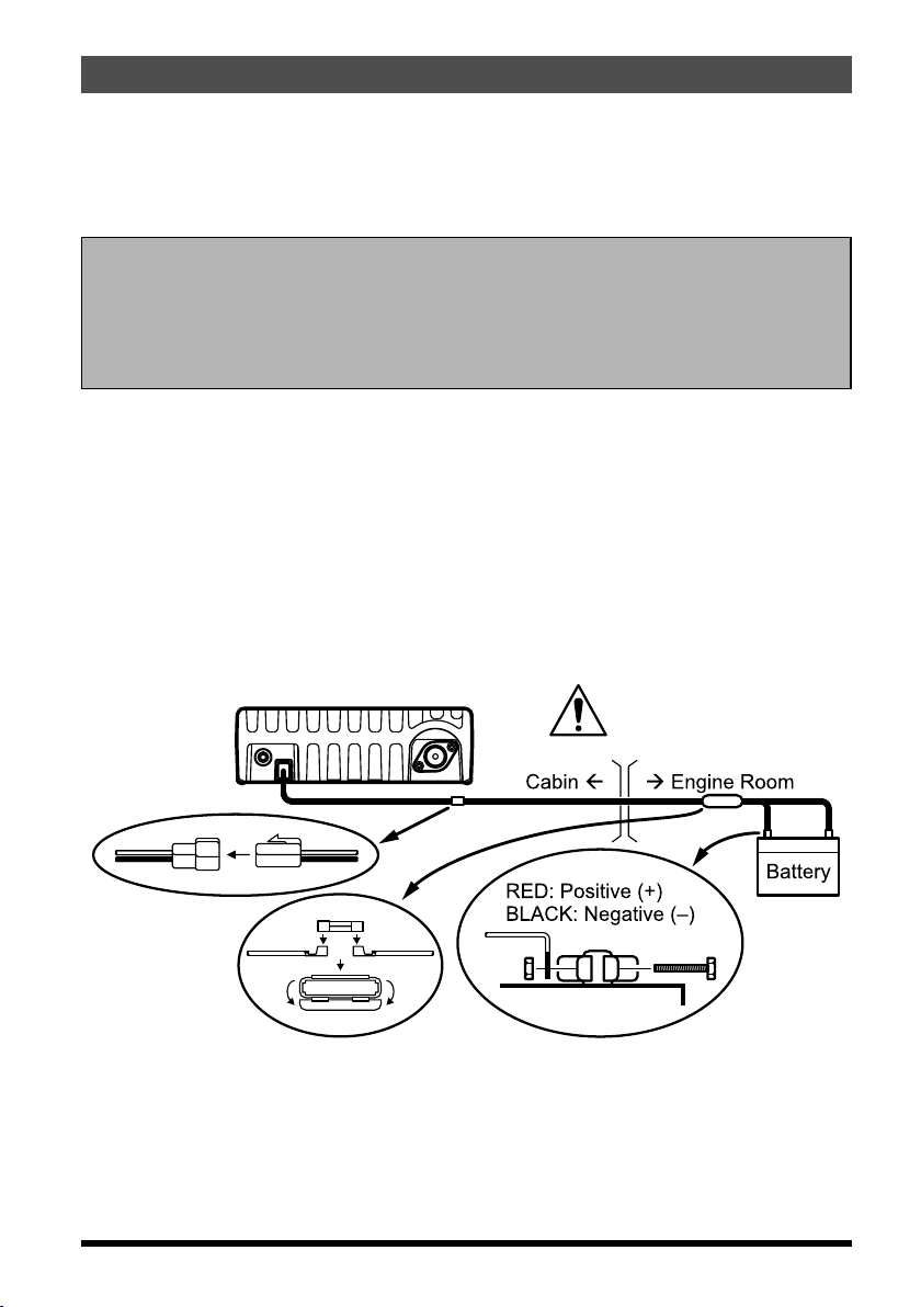
Mobile Power Connections
To minimize voltage drop and avoid blowing the vehicle’s fuses, connect the supplied
DC power cable directly to the battery terminals. Do not attempt to defeat or bypass the
DC cable’s fuse - it is there to protect you, your transceiver, and your vehicle’s electrical
system.
Warning!
Never apply AC power to the power cable of the FT-2980R, nor DC voltage
greater than 15.8 Volts. When replacing the fuse, only use a 25-A fuse. Failure
to observe these safety precautions will void the Limited Warranty on this
product.
Before connecting the transceiver, check the voltage at the battery terminals while
revving the engine. If the voltage exceeds 15 Volts, adjust the vehicle’s voltage regulator before proceeding with installation.
Connect the RED power cable lead to the POSITIVE (+) battery terminal, and the
BLACK power cable lead to the NEGATIVE (–) terminal. If you need to extend the
power cable, use #12 AWG or larger insulated, stranded copper wire. Solder the
splice connections carefully, and wrap the connections thoroughly with insulating
electrical tape.
Before connecting the cable to the transceiver, verify the voltage and polarity of the
voltage at the transceiver end of the DC cable using a DC voltmeter. Now connect
the transceiver to the DC cable.
FT-2980R
Fuse 25 A
Fuse Holder
NEVER remove the FUSE
holders from the DC cable.
Mobile Speakers
The optional MLS-100 External Speaker includes its own swivel-type mounting bracket,
and is available from your Yaesu dealer.
Other external speakers may be used with the FT-2980R, if they present the specified
4-Ohm impedance and are capable of handling the 3 Watts of audio output supplied by
the FT-2980R.
FT-2980R Operating Manual
11
Installation
Base Station Installation
The FT-2980R is ideal for base station use as well as in mobile installations. The FT2980R is specifically designed to integrate into your station easily, using the information
to follow as a reference.
AC Power Supplies
Operation of the FT-2980R from an AC line requires a power source capable of providing
at least 15 Amps continuously at 13.8 Volts DC. The FP-1023 and FP-1030A AC Power
Supplies are available from your Yaesu dealer to satisfy these requirements. Other wellregulated power supplies may be used, as well, if they meet the above voltage and current
specifications.
Use the DC power cable supplied with your transceiver for making power connections to
the power supply. Connect the RED power cable lead to the POSITIVE (+) power supply
terminal, and connect the BLACK power cable lead to the NEGATIVE (–) power supply
terminal.
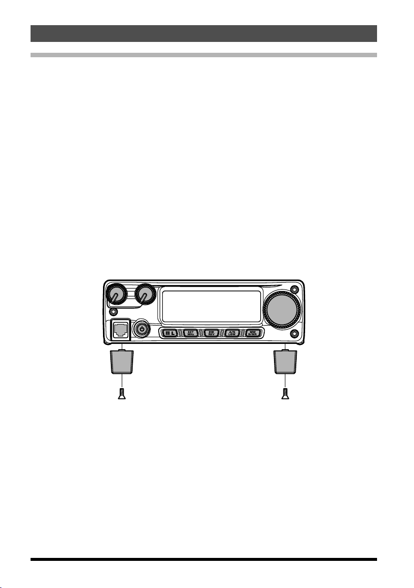
Base Station Feet
The supplied Base Station Feet allow the transceiver to be tilted upward for better viewing.
To install the Base Station Feet, remove the two screws affixing the front side of the
bottom cover, then install the Base Station Feet using these screws.
12
FT-2980R Operating Manual
Basic Operation
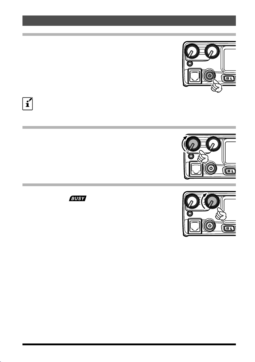
Turning the Transceiver On and Off
1. To turn the transceiver on, press and hold in the PWR key
for one second.
When you turn on the FT-2980R, the current DC supply
voltage is indicated on the LCD for 2 seconds. After this
interval, the display will switch its normal indication of the
operating frequency.
2. To turn the transceiver off, again press and hold in the
PWR key for one second.
You can change the Opening Message (DC supply voltage indication) to any
desired message (up to 6 characters) via Set Mode Item “31 OPN.MSG;” see
page 67 for details.
Adjusting the Audio Volume Level
Rotate the VOL control to adjust the receiver volume. Clockwise
rotation increases the audio output level.
Adjusting the Squelch Setting
Rotate the SQL control just to the point where the noise is
silenced and the
If the SQL control is set further clockwise, sensitivity to weak
signals is reduced.
A special “RF Squelch” feature is provided on this radio. This
feature allows you to set the squelch so that only signals
exceeding a certain S-meter level will open the squelch. See
page 18 for details
“ ” indicator on the display turns off.
13FT-2980R Operating Manual

Basic Operation
Frequency Navigation
1) Tuning Dial
Rotating the DIAL knob allows tuning in the pre-programmed steps. Clockwise rotation
of the DIAL knob causes the FT-2980R to be tuned toward a higher frequency, while
counter-clockwise rotation will lower the operating frequency.
Press the [MHz(SET)] key momentarily, then rotate the DIAL knob, to change the
frequency steps to 1 MHz per step. This feature is extremely useful for making rapid
frequency excursions over the wide tuning range of the FT-2980R. Instead of pressing
the [MHz(SET)] button, you may also press the [A] key on the Microphone’s keypad to
engage tuning in 1 MHz steps.
2) Direct Keypad Frequency Entry
The keypad of the MH-48A6J DTMF Microphone may be used for direct entry of the
operating frequency.
To enter a frequency from the MH-48
proper sequence. There is no “decimal point” key on the MH-48
there is a short-cut for frequencies ending in zero: press the [#] key after the last non-zero
digit.
Examples: To enter 146.520 MHz, press [1] à [4] à [6] à [5] à [2] à [0
To enter 146.000 MHz, press [1] à [4] à [6] à [#
If you cannot get the radio to accept the frequency entry, it is possible that
the channel steps are set to an incompatible value (e.g. if you have 25 kHz
steps set, you cannot set a frequency of 146.520 MHz). See page 18 to learn
how to change the channel step size.
A6J keypad, just press the numbered digits in the
A6J keypad. However,
]
]
3) Scanning
From the VFO mode, press the microphone’s [UP]/[DWN] keys momentarily to initiate
scanning toward a higher- or lower frequency, respectively. The FT-2980R will stop when
it receives a signal strong enough to break through the squelch threshold. The FT-2980R
will then hold on that frequency according to the setting of the “Resume” mode (Menu “41
SCAN)”; see page 39).
If you wish to reverse the direction of the scan (i.e. toward a lower frequency, instead of a
higher frequency), just rotate the DIAL knob one click in the counter-clockwise direction
while the FT-2980R is scanning. The scanning direction will be reversed. To revert to
scanning toward a higher frequency once more, rotate the DIAL knob one click clockwise.
Press the [UP]/[DWN] keys again to cancel scanning. You may also press the PTT button
momentarily; scanning will stop, but you will not transmit until you release the PTT button,
and press it again.
If you have enabled the “Severe Weather Alert” feature, you will occasion-
ally notice “WX” channels interspersed with the regular channels you are
scanning. This is normal, because your radio is constantly monitoring for weather
alerts. See page 16.
14
FT-2980R Operating Manual
Basic Operation
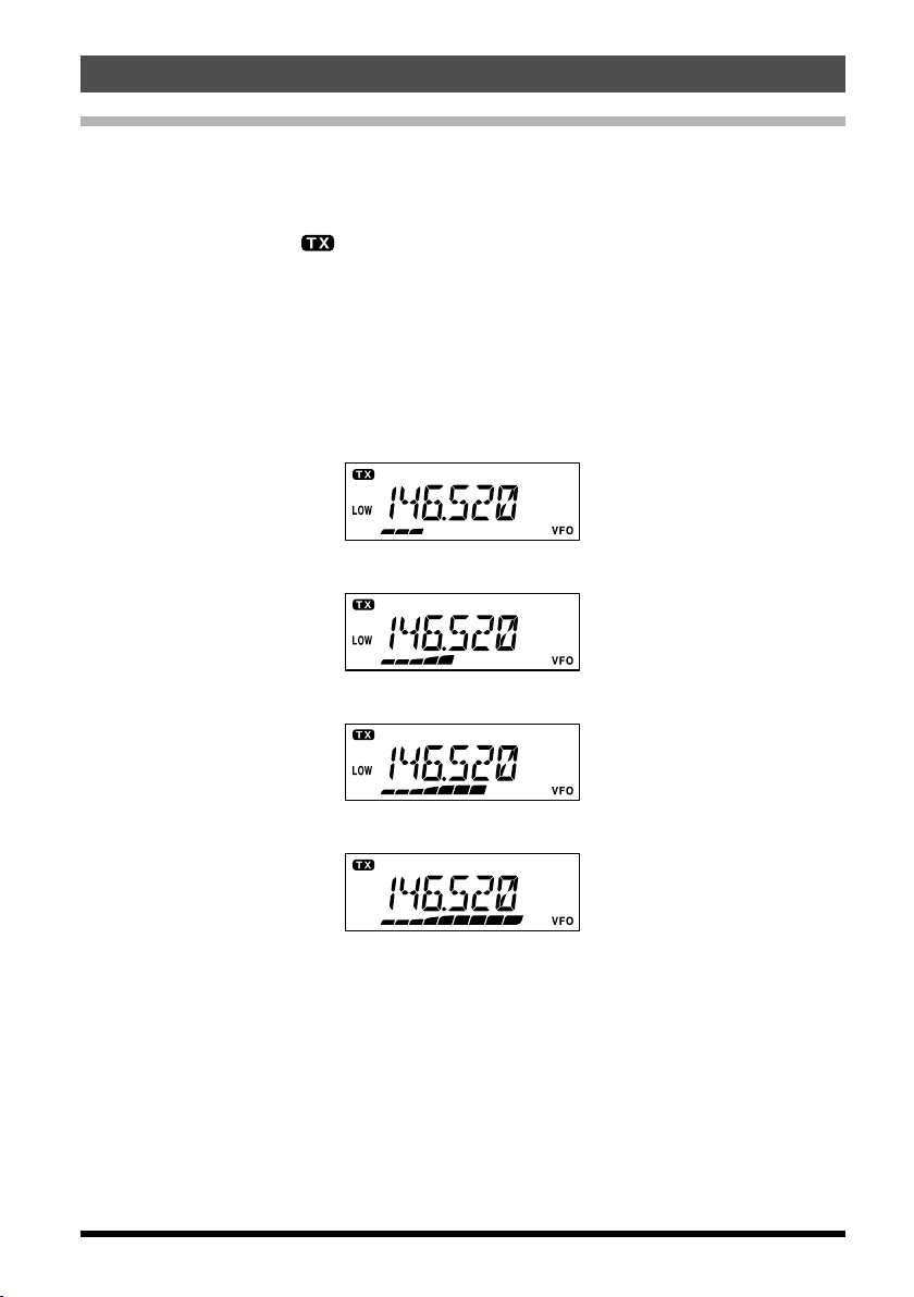
Transmission
To transmit, simply close the PTT (Push To Talk) switch on the microphone when the
frequency is clear. Hold the microphone approximately 1” (25 mm) from your mouth, and
speak into the microphone in a normal voice level. When your transmission is complete,
release the PTT switch; the transceiver will revert to the receive mode.
During transmission, the “
Changing the Transmitter Power Level
You can select from among a total of four transmit power levels on your FT-2980R.
To change the power level, press the [LOW(A/N)] key (or the microphone’s [C] key to
select one of four power settings. These power levels will be stored, in memory registers,
at the time of memory storage (see page 30 for details on Memory operation).
During transmission, the Bar Graph will deflect in the display, according to the power
output selected.
” indicator will appear at the upper left corner on the display.
Low 1 (5 watts)
Low 2 (10 watts)
FT-2980R Operating Manual
Low 3 (30 watts)
HIGH (80 watts)
15
Advanced Operation
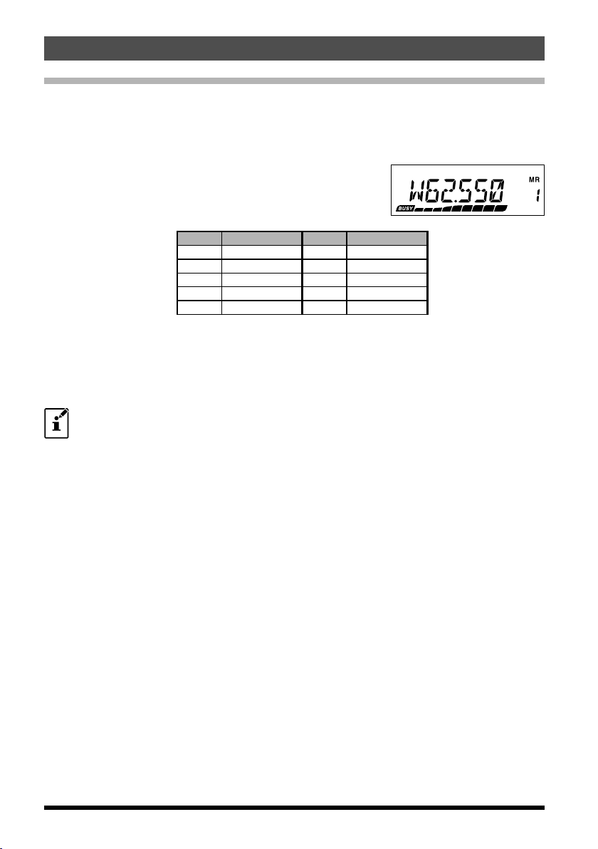
Weather Broadcast Reception (USA Version)
The FT-2980R includes a unique feature which allows reception of weather broadcasts in
the 160 MHz frequency range. Ten standard Weather Broadcast channels are pre-loaded
into a special memory bank.
To listen to a Weather Broadcast Channel:
1. Press the Microphone’s [P4] button to recall the Weath-
er Broadcast channels.
2. Turn t he DIAL knob to select the desired Weather
Broadcast channel.
CH Frequency CH Frequency
01 162.550 MHz 06 162.500 MHz
02 162.400 MHz 07 162.525 MHz
03 162.475 MHz 08 161.650 MHz
04 162.425 MHz 09 161.775 MHz
05 162.450 MHz 10 163.275 MHz
3. If you wish to check the other channels for activity by scanning, just press the Micro-
phone’s PTT switch.
4. To exit to normal operation, press the [P4] button again. Operation will return to the
VFO or Memory channel you were operating on before you began Weather Broadcast operation.
The [P4] key, one of the programmable keys, is assigned (default setting) as
the “WX Broadcast” one-touch access key. Please note that if you change/
assign another function to the [P4] key, one-touch access to the WX channel will
be unavailable.
Severe Weather Alert Feature
In the event of extreme weather disturbances, such as storms and hurricanes, NOAA (the
National Oceanic and Atmospheric Administration) sends a weather alert accompanied
by a 1050 Hz tone and subsequent weather report on one of the NOAA weather channels.
You may enable this feature via Menu Item “57 WX ALT”, if desired. See page 43 for
details.
When scanning the band or the “regular” memories, with the Severe Weather Alert feature
engaged, you will notice that the FT-2980R will break over to the Weather Channel bank
every five seconds, performing a quick scan of those channels in search for the 1050 Hz
alert tone. If the alert tone is received, operation will lock on the weather broadcast station
issuing the alert; otherwise, the radio will revert to the VFO or memory scan session in
progress without interruption.
When the alert tone is received, press the PTT button momentarily to disable the alarm,
and the Severe Weather message will now be audible from the speaker.
16 FT-2980R Operating Manual
Advanced Operation
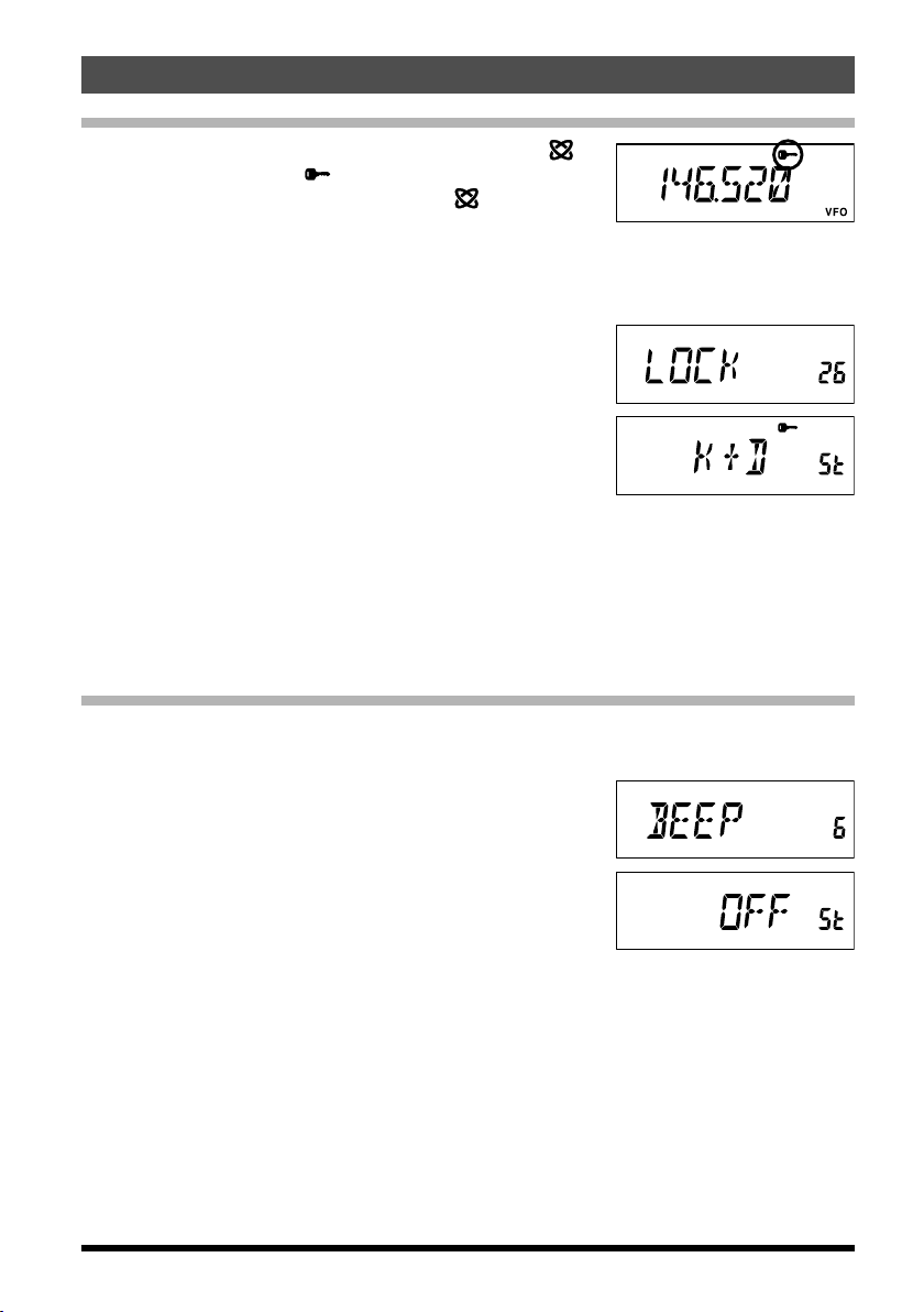
LOCK Feature
(L)]
[
To activate the locking feature, press and hold in the
key for one second. The “
To cancel locking, press and hold in the
for one second.
In order to prevent accidental frequency change or inadvertent transmission, various
aspects of the FT-2980R’s keys and knob may be locked out.
To lock out some or all of the keys, use the “Set” (Menu) mode, described below:
1. Press and hold in the [MHz(SET)] key for one second,
then rotate the DIAL knob to select “
2. Press the [MHz(SET)] key, then rotate the DIAL knob to
select the desired lockout combination.
: Just the front panel keys are locked out.
KEY
: Just the front panel DIAL knob is locked out.
DIAL
: Both the keys and DIAL knob are locked out.
K+D
: The PTT switch is locked (TX not possible).
PTT
: Both keys and PTT switch are locked out.
K+P
: Both DIAL knob and PTT switch are locked out.
D+P
: All of the above are locked out.
ALL
3. Press and hold in the [MHz(SET)] key for one second to save the new setting and
exit to normal operation.
” icon will appear on the LCD.
(L)]
[
key again
26 LOCK
”.
Keyboard Beeper
A key/button beeper provides useful audible feedback whenever a key/button is pressed.
If you want to turn the beeper off (or back on again):
1. Press and hold in the [MHz(SET)] key for one second,
then rotate the DIAL knob to select “
2. Press the [MHz(SET)] key, then rotate the DIAL knob to
set the display to “
3. Press and hold in the [MHz(SET)] key for one second to
save your new setting and exit to normal operation.
4. To turn the beep back on again, select “
(factory default)” in step 4 above.
: The beeper sounds when you press the keypad.
KEY
KY+SCN
: The beeper sounds when you press the keypad, or when the scanner
stops.
OFF
”.
6 BEEP
KEY
”.
” or “
KY+SCN
FT-2980R Operating Manual
17
Advanced Operation
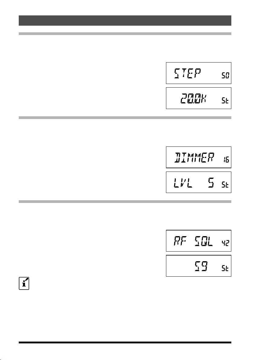
Channel Step Selection
Tuning steps are factory preset to default increments which are appropriate for the
country to which this radio is exported. You may have a reason to use a different step
size, however, and here is the procedure for changing the channel steps:
1. Press and hold in the [MHz(SET)] key for one second,
then rotate the DIAL knob to select “
2. Press the [MHz(SET)] key, then rotate the
DIAL knob to select the desired step size
(5/10/
12.5/15/20/25/50/100
3. Press and hold in the [MHz(SET)] key for one second to
save your new setting and exit to normal operation.
50 STEP
kHz).
Display Brightness
The FT-2980R display illumination has been specially engineered to provide high visibility
with minimal disruption of your “night vision” while you are driving. The brightness of the
display is manually adjustable, using the following procedure:
1. Press and hold in the [MHz(SET)] key for one second,
then rotate the DIAL knob to select “
2. Press the [MHz(SET)] key, then rotate the DIAL knob to
select a comfortable brightness level (
3. Press and hold in the [MHz(SET)] key for one second to
save your new setting and exit to normal operation.
16 DIMMER
LVL 0
”.
-
LVL10
”.
).
RF Squelch
A special RF Squelch feature is provided on this radio. This feature allows you to set the
squelch so that only signals exceeding a certain S-meter level will open the squelch.
To set up the RF squelch circuit for operation, use the following procedure:
1. Press and hold in the [MHz(SET)] key for one second,
then rotate the DIAL knob to select “
2. Press the [MHz(SET)] key, then rotate the DIAL knob to
select the desired signal strength level for the squelch
threshold (S1 - S9 or
3. Press and hold in the [MHz(SET)] key for one second to
save your new setting and exit to normal operation.
The receiver’s squelch will open based on the highest level set by the two
squelch systems, “Noise Squelch” and “RF Squelch”. For example:
1) If the Noise Squelch (SQL control) is set so that signals at a level of S-3 will
open the squelch, but the RF Squelch (Menu #42) is set to “S-9”, the squelch
will only open on signals which are S-9 or stronger on the S-meter.
2) If the RF Squelch is set to “S-3”, but the Noise Squelch is set to a high level
which will only pass signals which are Full Scale on the S-meter, the squelch
will only open on signals which are Full Scale on the S-meter. In this case, the
Noise Squelch overrides the action of the RF Squelch.
OFF
).
42 RF SQL
18
”.
FT-2980R Operating Manual
Repeater Operation
The FT-2980R includes a host of convenience features which makes operation on
amateur repeaters both efficient and enjoyable.
This transceiver offers three methods of setting up split-frequency operation on repeaters:
Manual selection of preset repeater shifts (Standard Repeater Shift);
Automatic Repeater Shift (ARS), providing automatic activation of repeater shifts
while operating within designated repeater frequency subbands; and
Independently stored transmit and receive frequencies (typically not corresponding
to established repeater frequency shifts).
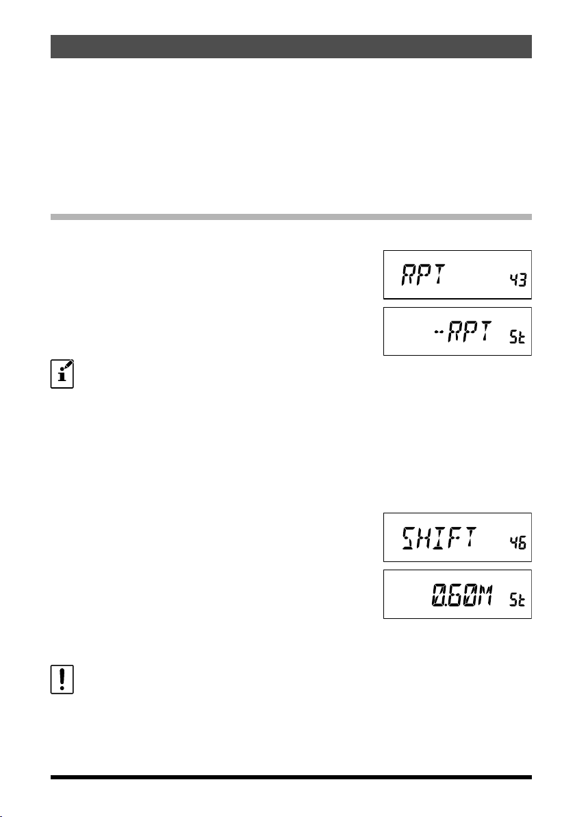
Standard Repeater Shift
To activate the standard shift manually, you may use the Set (Menu) mode:
1. Press and hold in the [MHz(SET)] key for one second,
then rotate the DIAL knob to select “
2. Press the [MHz(SET)] key, then rotate the DIAL knob
to select the desired shift direction (
).
SIMP
3. Press and hold in the [MHz(SET)] key for one second to
save your new setting and exit to normal operation.
You also may program one of the Microphone’s programmable keys ([P1] ~
[P4])
to allow quick access to the above procedure. See page 56 for details
on the setup of the programmable keys.
With repeater shift activated, you can temporarily reverse the transmit and receive
frequencies by pressing the [REV(DW)] key (or the microphone’s [B] key). Use this
feature to display the transmit frequency without transmitting, and to check the strength
of signals on a repeater uplink frequency (so as to determine whether or not a particular
station is within “Simplex” range, for example).
The repeater offset is fixed to 600 kHz from the factory. You can change the offset by the
following procedure, if needed for vacation travel or other
purposes:
1. Press and hold in the [MHz(SET)] key for one second,
then rotate the DIAL knob to select “
2. Press the [MHz(SET)] key, then rotate the DIAL knob
to set the desired offset. Note that the resolution of the
“standard” repeater shift is to the nearest 50 kHz multiple.
3. Press and hold in the [MHz(SET)] key for one second to save your new setting and
exit to normal operation.
Do not use this procedure for programming of an “odd split” type repeater
pair! The process for programming odd splits is shown on page 31.
43 RPT
46 SHIFT
”.
–RPT, +RPT
”.
, or
19FT-2980R Operating Manual
Repeater Operation
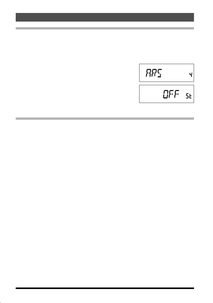
Automatic Repeater Shift
The ARS (Automatic Repeater Shift) feature in this transceiver allows easy and convenient
repeater operation by automatically activating the repeater shift function whenever you
tune to a standard repeater subband. The ARS function is preset at the factory to conform
to the standards for the country to which it is exported.
The ARS function is enabled at the factory. To disable it:
1. Press and hold in the [MHz(SET)] key for one second,
then rotate the DIAL knob to select “
2. Press the [MHz(SET)] key, then rotate the DIAL knob to
change the display to “
3. Press and hold in the [MHz(SET)] key for one second to
save your new setting and exit to normal operation.
To enable the ARS function again, select “ON” in step 2
above.
OFF
”.
Checking the Repeater Uplink (Input) Frequency
It often is helpful to be able to check the uplink (input) frequency of a repeater, to see if
the calling station is within direct (“Simplex”) range.
To do this, just press the [REV(DW)] key. You’ll notice that the display has shifted to the
repeater uplink frequency. Press the [REV(DW)] key again to cause operation to revert
to normal monitoring of the repeater downlink (output) frequency. While you are listening
on the input frequency to the repeater using the [REV(DW)] key, the repeater offset icon
will blink.
4 ARS
”.
20
FT-2980R Operating Manual
 Loading...