

Page 1
Quick Guide
1
Page 2

Contents
Daily Use 4
Display 5
Display Keys 5
Contrast Setup 6
Reset the System 6
Function Keys 7
Basic Setup; Pump Control 1 10
Signal List 10
Configuration 13
Step by Step: 14
Operation of the Pumps 15
Overview Screen for Pump Control 1 16
Screen Information: 16
Start/Stop Levels 18
Manual Operation 20
Pump Data 22
Basic Flowchart 23
2
Page 3

Introduction
Thank you for choosing the MJK Connect® or Mµ Connect® controller and
monitoring unit. MJK Connect
and put into operation. To get the full advantages of MJK Connect
Connect® MJK recommends that future users read this manual to get familiar
with all details concerning MJK Connect
®
and Mµ Connect® are easy to install, calibrate
®
and Mµ Connect®. The equipment
®
and Mµ
should be treated and used as directed by MJK Automation A/S to ensure a
stable operation and precise measurements.
Liability
MJK Automation A/S are liable to the common rules of Danish law on product liability, however, the liability is reduced to coverage of our public liability
insurance of products. To the extent where nothing else follows in lines of
invariable rules of law, we are not liable for loss of profits and working deficits
or other indirect losses.
Changes
As our products are developed continuously we reserve the right to make any
alterations without prior notice.
Trademarks & Acknowledgements
Mµ Connect
Shuttle
Expert™ is a trademark of MJK Automation A/S, Denmark.
®
VLT
is a registered trademark of Danfoss A/S.
®
, Connect®, MagFlux®, Chatter®, SuSix®, Oxix®, pHix® and
®
are registered trademarks of MJK Automation A/S, Denmark.
MJK Automation is a Xylem Brand.
®
A complete manual for Connect
, including all menus and functions, technical
specifications and more can be found on our website as pdf.
http://www.mjk.dk/downloads/downloads-products/downloads-rtu/
downloads-connect/
A complete manual for Instrument Link, including all menus and functions,
technical specifications and more can be found on our website as pdf.
http://www.mjk.dk/downloads/downloads-products/downloadsaccessories/
downloads-rtusoftware/
3
Page 4
Daily Use
This is a Quick Guide to get started with your Connect®.
The following examples in this section will show and explain how a Connect® is configured as pump controller for a wastewater pump station with 2
pumps.
In Connect® the function “Pump Control 1” is used to control the pumps
through the level in the pumping sump.
The complete manual for Connect® and Mµ Connect® can be found on
www.mjk.com.
This Quick Guide applies to Connect® with the following firmware versions:
Firmware Versions
Product Number Revision
Connect® Base Unit 844003 007-017
Connect® Display 841021 003
4
Page 5
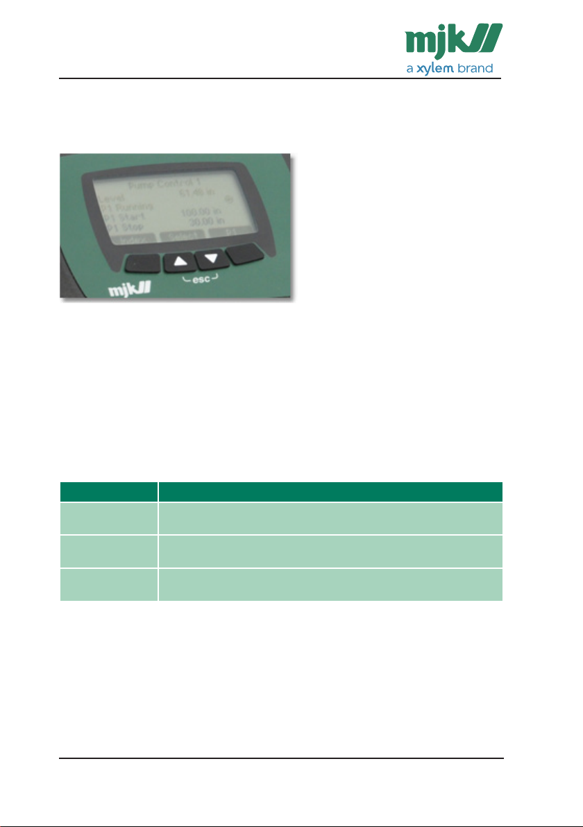
Display
The 4 soft keys located below the display are used to navigate the menus during the daily operation of Connect®.
Display Keys
Numerical keys and soft keys are used for startup configuration and normal
operation. Which of these is decided by the installed display firmware.
The functions of the 4 soft keys are shown at the bottom of the display. The
functions of the soft keys depends on which menu or function is currently active/shown.
Symbols and current functions are described in detail in the individual menu
sections. The numerical keyboard on the right can be used for direct menu
selections and alpha-numerical typing of names and texts.
Key function Description
Left button The left button usually changes between Menu and Index (Toggle
Up/Down Arrows The arrows are labelled “Select” where you can move up and down
Right button The right button is used mainly to confirm your choice and/or to
function)
in the menus.
continue to the next screen.
5
Page 6
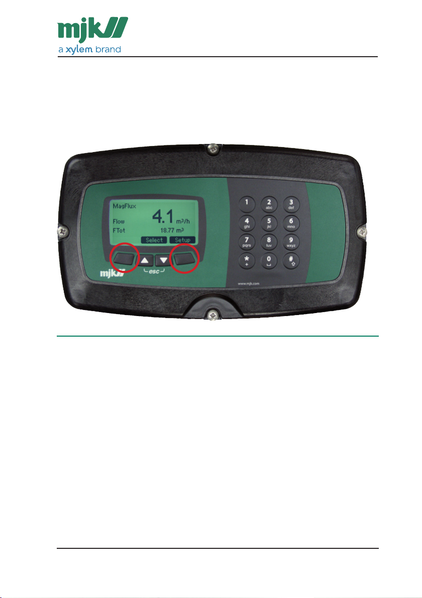
Contrast Setup
Configure the display contrast by pressing the two outer soft keys simultaneously as shown with the red circles to the right. Then press the up/down
arrows until you get the desired contrast.
Save the changes by pressing the 2 outer soft keys simultaneously again.
Reset the System
It is possible to reset the system and refresh all system views and key combinations by pressing all four soft keys down simultaneously. This is especially
useful in situations such as a service technician having to change the language to one he understands. A reset of the system will change the language
to the default English (GB).
Please note: A reset of the system should not be confused with the very
comprehensive Factory Settings>Restore Connect, which will erase all local
configurations and setup and replace them with the original factory settings.
6
Page 7
Function Keys
The daily operation of Connect
®
and Mµ Connect® is done through the built-in
function keys 1-9.
The function keys (numerical keyboard) is also used for direct menu selection
and typing names and texts.
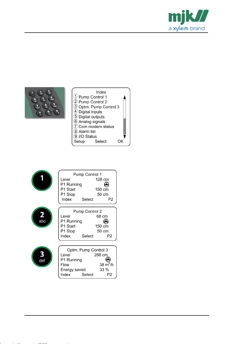
Each function key has pre-defined views and can be customized as needed.
When selecting Index, an overview of the defined overview
screens are created. Use this
screen to make a quick switch
to the selected screen.
Function keys 1 to 3 have the following functions:
Pump Control 1. This screen is a
standard screen for Connect
®.
This screen shows current level, pump
1 operating condition and first set of
start/stop levels
Pump Control 2. This screen is a
standard screen for Connect
®
This screen shows current level, pump
1 operating condition and first set of
start/stop levels
The function keys 1 to 3 are only shown when “Create Overview Screen” in
the function menu has been done.
7
Page 8
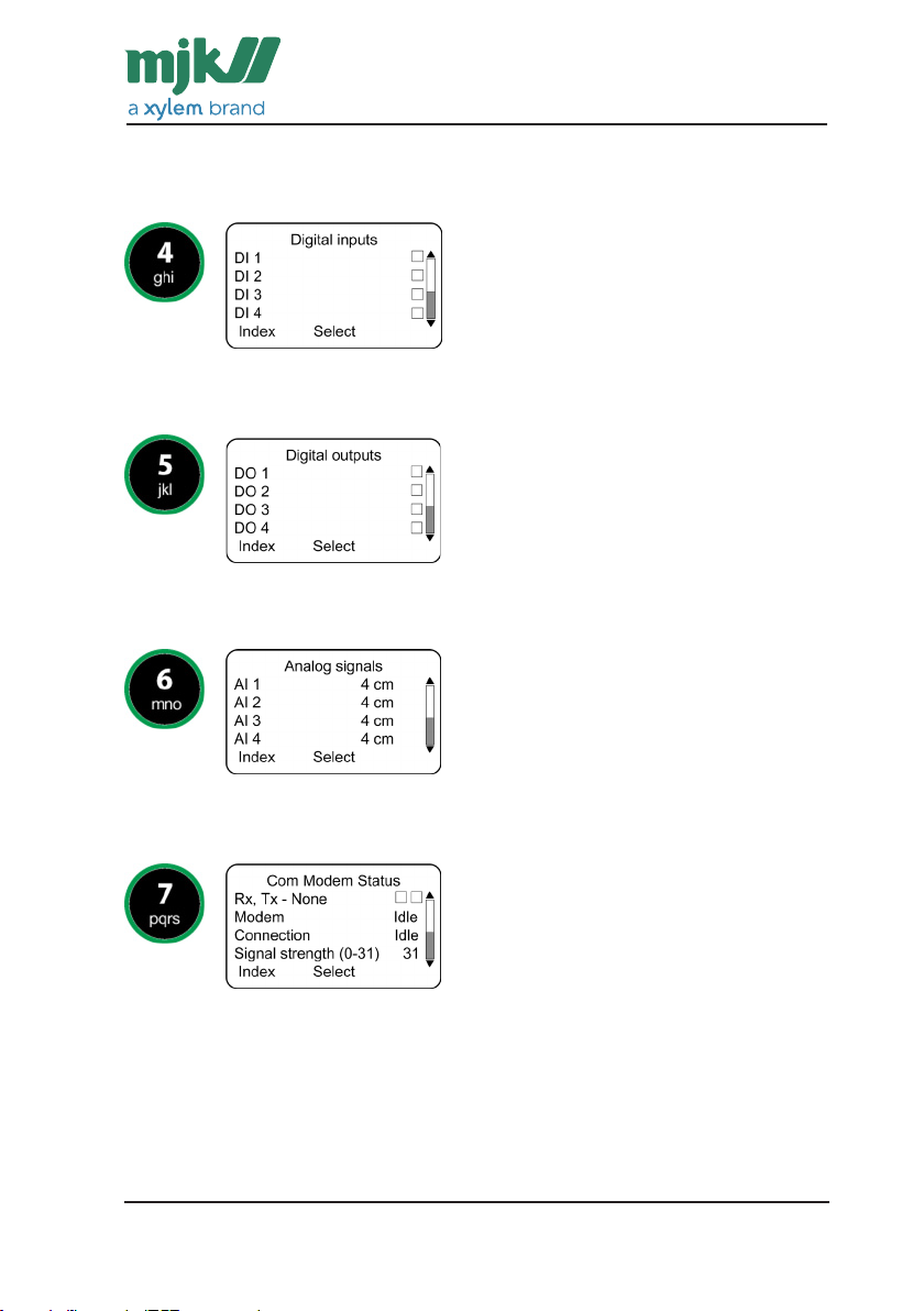
The function keys 4 to 9 have the following functions:
Function key 4. Digital Inputs
Shows status on all digital inputs.
Function key 5. Digital Outputs
Shows status on all digital outputs.
Function key 6. Analog Inputs
Shows status on all analog outputs.
Function key 7. Communication Status
Shows status on the communication. Is dependent on chosen communication
module.
8
Page 9
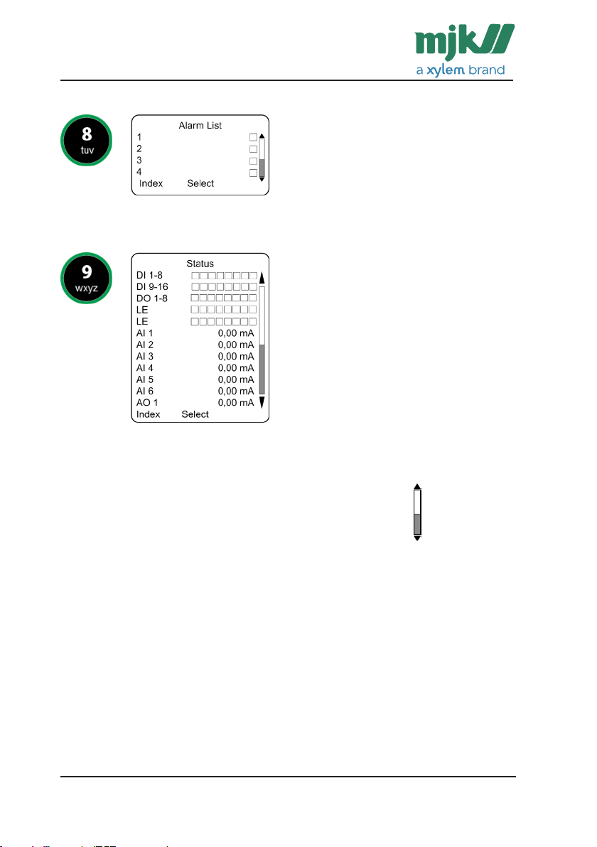
Function key 8. Alarm List
Shows status on alarms.
Function key 9. I/O Status
Shows status on all inputs/outputs and analog limits, virtual analog outputs
and logical flags (LF).
Please note: Scroll with the up/down arrows to view more.
9
Page 10

Basic Setup; Pump Control 1
This section will show and explain how a Connect® is configured as pump
controller for a wastewater pump station with 2 pumps.
The function “Pump Control 1” is used to control the pumps through the level
in the pumping sump.
The picture shows an example on 2-pump station with 2 submerged pumps.
Signal List
First step is to create a signal list to create a full overview of the signal from
the pump controller to the pumps and from the pumps to the controller.
The following table shows examples from an typical pump station.
10
Page 11

The list shows signals connected to the digital inputs in this example.
Digital
Input
DI 1 Operation P1 NO 0 sec. In use In use
DI 2 Operation P2 NO 5 sec. In use In use
DI 3
DI 4 Thermo alarm P1 NO 15 sec. Alarm
DI 5 Thermo alarm P2 NO 15 sec. Alarm
DI 6
DI 7 Klixon P1 NO 0 sec. Alarm
DI 8 Klixon P1 NO 0 sec. Alarm
DI 9
DI 10 MAN-0-AUT P1 NO Alarm
DI 11 MAN-0-AUT P1 NO Alarm
DI 12
DI 13
DI 14
DI 15
DI 16 High Level
Signal Name Relay
Function
NO Alarm
Switch
Delay Alarm /
In use
Alternation
The list shows the signals connected to the digital outputs in the example.
Digital
output
DO 1 Start/Stop P1 NO-constant 0 sec. 0 sec.
DO 2 Start/Stop P2 NO-constant 0 sec. 0 sec.
DO 3
DO 4
DO 5
DO 6
DO 7
DO 8 Joint reset of
Signal Name Relay Function Close time
(seconds on time)
NO-time controlled 1 sec. 0 sec.
thermo error
Delay
11
Page 12

Digital
Input
AI 1 Level 0 300 Level 0 sec.
AI 2 Power P1 0 10 Other Units 0 sec.
AI 3 Power P2 0 10 Other Units 0 sec.
AI 4
AI 5
AI 6
AI 7
Signal Name Scaling Scaling
20 mA
Unit Average
Analog
limits
AI 1 High In use High Level alarm XX 5 sec. In use
AI 1 Low Not in use AI 1 LA 0 0 Not in use
AI 2 High In use High Level alarm P1 0 0 Not in use
AI 2 Low Not in use AI 2 LA 0 0 Not in use
AI 3 High In use High Level alarm P2 0 0 Not in use
AI 3 Low Not in use AI 3 LA 0 0 Not in use
AI 4 High Not in use AI 4 HA 0 0 Not in use
AI 4 Low Not in use AI 4 LA 0 0 Not in use
AI 5 High Not in use AI 5 HA 0 0 Not in use
AI 5 Low Not in use AI 5 LA 0 0 Not in use
AI 6 High Not in use AI 6 HA 0 0 Not in use
AI 6 Low Not in use AI 6 LA 0 0 Not in use
In use
Not in use
Signal Name Setpoint Delay Call
12
Page 13

Configuration
Next step is to configure the Connect® based on the shown signal list. In the
function menu, choose Pump Control 1 and setup the specific menu items as
described in the signal list.
Go to Functions Menu and choose Pump Control 1, which contains the following items:
• Number of Pumps: Number of pumps in the wasterwater pump station.
• Measurement: The analog input on which the level transmitter is mounted
on and scaling and signal name.
• Pumps Setup
• Start/Stop levels: start and stop levels for current number of pumps.
• Control Word: 16-bit control word for intelligent pump controlling.
• Additional Functions with:
• Flow calculation
• Setpoint displacement
• Depth pumping
• Create Overview Screen: Connect will setup the screen 1 with the entered
information on overview screen 1.
13
Page 14

Step by Step:
The display shows the setup like this
Select Functions Menu Select Pump Control 1 Select In use
Enter 2 and OK Enter 2 and OK
14
Page 15

Operation of the Pumps
This section is based on the function “Pump Control 1” which is the most
used Pump function.
Function Key 1 is the screen used for the pump control and will
typically be the same screen as in the Connect when working on the
station.
Please note that the pre-defined view described here can be customized to
your needs.
Select Function Key 1 for the daily use of the pump control 1.
Overview display 1 is standard and located in the function section Pump
Control 1. The most current pump information is displayed here: Actual level,
in use/not in use and the start/stop levels of the pump.
Note: If you leave Connect® with this setup, this will be the first you see on
the pump station at next visit.
15
Page 16

Overview Screen for Pump Control 1
By pressing the right key below the display (P2), the display changes to a
similar one for Pump 2. The key will then change name to P3 - P4, depending
on how many pumps have been created in the function Pump Control 1.
Navigate with the up/down arrows below Select. Arrow down will select the
first/top line, another arrow down will select the second line, etc.
Note: There can be discrepancies from this screen if lines have been added/
changed by the user.
Screen Information:
Text line Description
Pump Control 1 This is the name of the function. You can change this to for example
Level Shows the current level in the pumping sump.
P1 Running The operation status of the pump. This is shown as text and icons.
P1 Start The start level of the pump is changed here. Select the line and
P1 Stop The stop level of the pump is changed here. Select the line and
Index Switch between the functions menu and the overview screens.
Select Use up/down arrows to scroll in the current screen and selecting a
P2 Use the right key below the display to change to a similar view for
the name of the pump station
See below list.
enter the desired start level on the display with the numerical keyboard. Save with OK.
enter the desired stop level on the display with the numerical keyboard. Save with OK.
line or function.
Pump 2. The key will then change name to P3 - P4, depending on
how many pumps have been created in the function Pump Control
1.
16
Page 17

Operation status of
Icon Description
Pump
P1 Running Digital output when the pump is in use and the
P1 stopped Digital output when the pump has stopped and
P1 error Digital output when the pump is in use and the
P1 Blocked Digital output when the pump is not in use.
feedback signal is ok.
the feedback signal is missing.
feedback signal is missing.
17
Page 18

Start/Stop Levels
How to change a start or stop level:
Press Function key 1 to enter the overview screen for Pump Control 1.
Use the arrow keys
under the display to
click down and select
the line P1 Start.
You can now press the arrow down and change the stop level the same
way as you changed the start level.
Use the arrow keys
under the display to
click down and select
the line P1 Stop.
The last digit in the
start level is now selected. Enter the new
start level by using the
numerical keyboard on
the right.
The last digit in the
stop level is now selected. Enter the new
stop level by using the
numerical keyboard on
the right.
When the new value
has been entered, save
the value in Connect®
with OK.
When the new value
has been entered, save
the value in Connect®
with OK.
18
Page 19

If you need to change the start/stop levels on the next pumps, press once
more on the down arrow from Stop Level P1.
Now P2 will be displayed in the lower right corner. Press the right soft key
under P2 and the screen will change to Pump 2.
Repeat the procedure as described above.
By pressing the right soft key again, you will toggle between the number of
pumps chosen for Pump Control 1.
Note: It is a prerequisite that Pump Control has been set up and “Create
Overview Screen” has been carried out.
If you have chosen a higher stop level than start level, the function will
change from emptying to filling.
19
Page 20

Manual Operation
How to start or stop a pump manually:
Click the Function
Key 1 to show the
overview screen for
Pump Control 1.
The pump is now stopped and will not start until the start level has been
reached again and it is the pump’s turn in the alternation.
Note: Only one pump can be started, provided that the level in the pump
sump is above the stop level.
Use the up/down arrows
to select line 2, which
shows the operation
status. press “Operate”
button to enter the Pump
1 menu.
If you wish to start a
pump, use the arrow
keys to go down and select the Start Pump line
and click OK.
20
Page 21

If you wish to stop a pump in use, use the up/down arrows to select Stop
Pump and press OK.
If you need to start or stop one of the next pumps, press once more on the
down arrow from Stop Level P1.
Now P2 will be displayed in the lower right corner. Press the right soft key
below P2 and the screen will change to Pump 2.
Repeat the procedure as described above.
There are 4 views and icons of the Pump Status.
Operation status
Icon Description
of Pump
P1 Running Digital output when the pump is running and the feed-
P1 Stopped Digital output when the pump has stopped and the feed-
P1 Error
P1 Blocked Digital output when the pump is not in use.
back signal is ok.
back signal is missing.
Digital output when the pump is in use and the feedback
signal is missing.
Note: By pressing the right soft key again, you will toggle between the
number of pumps chosen for Pump Control 1.
It is a prerequisite that Pump Control has been set up and “Create Overview
Screen” has been carried out.
Scroll with the arrow keys to see more information.
21
Page 22

Pump Data
The overview screen View Data provides a full overview of operation data for
the pump.
In this view, View Data is selected and an overview screen of pictures for the
selected pump’s data is shown.
You can choose between 3 different data screens.
Totals Today Yesterday
Text line Description
Pump 1 This is the name of the function. You can change it to e.g. the
P1 Total/Today/
Yesterday Cnt.
P1 Total/Today/
Yesterday tim.
P1 Volume/Total/
Today/ Yesterday
Status Go back to the main screen for Pump Control 1
Select Up/down arrows are used to scroll up and down in the current
Next Change to next pump data screen.
pump number or any individual name.
Count values (number of starts) for the selected pumps.
The counter is connected to the selected DO for the pump. The
counter is shown as totals, today values (since midnight) and as
yesterday values
Time values (on-time) for the selected pumps. The counter is connected to the selected DO for the pump.
The counter is shown as totals, today values (since midnight) and
as yesterday values.
Volume values (number of units) for the selected pump. The counter is connected to the selected pump.
The counter is shown as totals, today values (since midnight) and
as yesterday values.
screen and select a line or function.
Note: It is a prerequisite that Pump Control has been set up and “Create
Overview Screen” has been carried out.
22
Page 23

Basic Flowchart
23
Page 24

Liability
DK: +45 45 56 06 56
NO: +47 69 20 60 70
SE: +46 53 31 77 50
NL: +31 251 672171
USA: +1 847 482 8655
AUS: +61 3 9758 8533
MJK Automation A/S
MJK Automation A/S are liable to the common
rules of Danish law on product liability, however,
the liability is reduced to coverage of our public liability insurance of products. To the extent where
nothing else follows in lines of invariable rules of
law, we are not liable for loss of profits and working deficits or other indirect losses.
Changes
As our products are developed continuously, we
reserve the right to make any alterations without
prior notice.
EN 6.05 Connect QG 1210
24
 Loading...